Sistema de Pré-acção de Interbloqueio Simples Preaction ... · Actuação Piloto Pneumática...
16
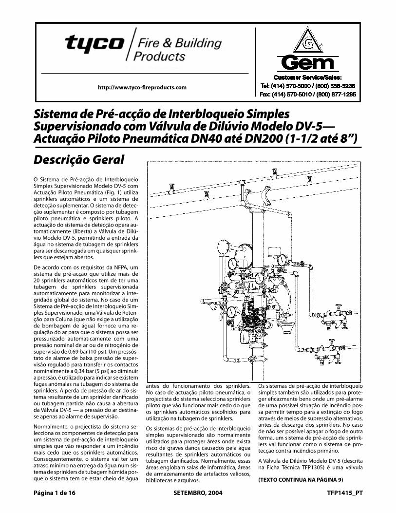
General Customer Service/Sales: Tel: (414) 570-5000 / (800) 558-5236 Fax: (414) 570-5010 / (800) 877-1295 Customer Service/Sales: Tel: (414) 570-5000 / (800) 558-5236 Fax: (414) 570-5010 / (800) 877-1295 Customer Service/Sales: Tel: (414) 570-5000 / (800) 558-5236 Fax: (414) 570-5010 / (800) 877-1295 Customer Service/Sales: Tel: (414) 570-5000 / (800) 558-5236 Fax: (414) 570-5010 / (800) 877-1295 Customer Service/Sales: Tel: (414) 570-5000 / (800) 558-5236 Fax: (414) 570-5010 / (800) 877-1295 Customer Service/Sales: Tel: (414) 570-5000 / (800) 558-5236 Fax: (414) 570-5010 / (800) 877-1295 Customer Service/Sales: Tel: (414) 570-5000 / (800) 558-5236 Fax: (414) 570-5010 / (800) 877-1295 Customer Service/Sales: Tel: (414) 570-5000 / (800) 558-5236 Fax: (414) 570-5010 / (800) 877-1295 Customer Service/Sales: Tel: (414) 570-5000 / (800) 558-5236 Fax: (414) 570-5010 / (800) 877-1295 Customer Service/Sales: Tel: (414) 570-5000 / (800) 558-5236 Fax: (414) 570-5010 / (800) 877-1295 Customer Service/Sales: Tel: (414) 570-5000 / (800) 558-5236 Fax: (414) 570-5010 / (800) 877-1295 Customer Service/Sales: Tel: (414) 570-5000 / (800) 558-5236 Fax: (414) 570-5010 / (800) 877-1295 Customer Service/Sales: Tel: (414) 570-5000 / (800) 558-5236 Fax: (414) 570-5010 / (800) 877-1295 Customer Service/Sales: Tel: (414) 570-5000 / (800) 558-5236 Fax: (414) 570-5010 / (800) 877-1295 Customer Service/Sales: Tel: (414) 570-5000 / (800) 558-5236 Fax: (414) 570-5010 / (800) 877-1295 Customer Service/Sales: Tel: (414) 570-5000 / (800) 558-5236 Fax: (414) 570-5010 / (800) 877-1295 Customer Service/Sales: Tel: (414) 570-5000 / (800) 558-5236 Fax: (414) 570-5010 / (800) 877-1295 Customer Service/Sales: Tel: (414) 570-5000 / (800) 558-5236 Fax: (414) 570-5010 / (800) 877-1295 Customer Service/Sales: Tel: (414) 570-5000 / (800) 558-5236 Fax: (414) 570-5010 / (800) 877-1295 Customer Service/Sales: Tel: (414) 570-5000 / (800) 558-5236 Fax: (414) 570-5010 / (800) 877-1295 Customer Service/Sales: Tel: (414) 570-5000 / (800) 558-5236 Fax: (414) 570-5010 / (800) 877-1295 Customer Service/Sales: Tel: (414) 570-5000 / (800) 558-5236 Fax: (414) 570-5010 / (800) 877-1295 Customer Service/Sales: Tel: (414) 570-5000 / (800) 558-5236 Fax: (414) 570-5010 / (800) 877-1295 Customer Service/Sales: Tel: (414) 570-5000 / (800) 558-5236 Fax: (414) 570-5010 / (800) 877-1295 Customer Service/Sales: Tel: (414) 570-5000 / (800) 558-5236 Fax: (414) 570-5010 / (800) 877-1295 Customer Service/Sales: Tel: (414) 570-5000 / (800) 558-5236 Fax: (414) 570-5010 / (800) 877-1295 Customer Service/Sales: Tel: (414) 570-5000 / (800) 558-5236 Fax: (414) 570-5010 / (800) 877-1295 http://www.tyco-fireproducts.com Página 1 de 16 SETEMBRO, 2004 TFP1415_PT Descrição Geral O Sistema de Pré-acção de Interbloqueio Simples Supervisionado Modelo DV-5 com Actuação Piloto Pneumática (Fig. 1) utiliza sprinklers automáticos e um sistema de detecção suplementar. O sistema de detec- ção suplementar é composto por tubagem piloto pneumática e sprinklers piloto. A actuação do sistema de detecção opera au- tomaticamente (liberta) a Válvula de Dilú- vio Modelo DV-5, permitindo a entrada da água no sistema de tubagem de sprinklers para ser descarregada em quaisquer sprink- lers que estejam abertos. De acordo com os requisitos da NFPA, um sistema de pré-acção que utilize mais de 20 sprinklers automáticos tem de ter uma tubagem de sprinklers supervisionada automaticamente para monitorizar a inte- gridade global do sistema. No caso de um Sistema de Pré-acção de Interbloqueio Sim- ples Supervisionado, uma Válvula de Reten- ção para Coluna (que não exige a utilização de bombagem de água) fornece uma re- gulação do ar para que o sistema possa ser pressurizado automaticamente com uma pressão nominal de ar ou de nitrogénio de supervisão de 0,69 bar (10 psi). Um pressós- tato de alarme de baixa pressão de super- visão regulado para transferir os contactos nominalmente a 0,34 bar (5 psi) ao diminuir a pressão, é utilizado para indicar se existem fugas anómalas na tubagem do sistema de sprinklers. A perda de pressão de ar do sis- tema resultante de um sprinkler danificado ou tubagem partida não causa a abertura da Válvula DV-5 — a pressão do ar destina- se apenas ao alarme de supervisão. Normalmente, o projectista do sistema se- lecciona os componentes de detecção para um sistema de pré-acção de interbloqueio simples que vão responder a um incêndio mais cedo que os sprinklers automáticos. Consequentemente, o sistema vai ter um atraso mínimo na entrega da água num sis- tema de sprinklers de tubagem húmida por- que o sistema tem de estar cheio de água Sistema de Pré-acção de Interbloqueio Simples Supervisionado com Válvula de Dilúvio Modelo DV-5— Actuação Piloto Pneumática DN40 até DN200 (1-1/2 até 8”) antes do funcionamento dos sprinklers. No caso de actuação piloto pneumática, o projectista do sistema selecciona sprinklers piloto que vão funcionar mais cedo do que os sprinklers automáticos escolhidos para utilização na tubagem de sprinklers. Os sistemas de pré-acção de interbloqueio simples supervisionado são normalmente utilizados para proteger áreas onde exista risco de graves danos causados pela água resultantes de sprinklers automáticos ou tubagem danificados. Normalmente, essas áreas englobam salas de informática, áreas de armazenamento de artefactos valiosos, bibliotecas e arquivos. Os sistemas de pré-acção de interbloqueio simples também são utilizados para prote- ger eficazmente bens onde um pré-alarme de uma possível situação de incêndio pos- sa permitir tempo para a extinção do fogo através de meios de supressão alternativos, antes da descarga dos sprinklers. No caso de não ser possível apagar o fogo de outra forma, um sistema de pré-acção de sprink- lers vai funcionar como o sistema de pro- tecção contra incêndios primário. A Válvula de Dilúvio Modelo DV-5 (descrita na Ficha Técnica TFP1305) é uma válvula (TEXTO CONTINUA NA PÁGINA 9)
Transcript of Sistema de Pré-acção de Interbloqueio Simples Preaction ... · Actuação Piloto Pneumática...
GeneralDescriptionThe Model DV-5 Supervised Single In-terlock Preaction System with Dry PilotActuation (Fig. 1) utilizes automaticsprinklers and a supplemental detec-tion system. The supplemental detec-tion system is comprised of dry pilotlines and pilot sprinklers. Actuation ofthe detection system automatically op-erates (releases) the Model DV-5 Del-uge Valve, allowing water to flow intothe sprinkler piping system and to bedischarged from any sprinklers thatmay be open.
In accordance with the requirementsof the National Fire Protection Asso-ciation, a preaction system employingmore than 20 automatic sprinklers is tohave the sprinkler piping automaticallysupervised to monitor the overall in-tegrity of the system. In the case of aSupervised Single Interlock PreactionSystem, a Riser Check Valve (thatdoes not require the use of primingwater) provides an air check so thatthe system can be automatically pres-surized with a nominal supervisory airor nitrogen pressure of 10 psi (0,69bar). A supervisory low pressure alarmswitch that is set to transfer its contactsat nominally 5 psi (0,34 bar), on de-creasing pressure, is utilized to indi-cate whether there are any abnormalleaks in the sprinkler system piping.Loss of air pressure from the systemas a result of a damaged sprinkler orbroken piping will not cause the DV-5Valve to open — the air pressure is forsupervisory alarm only.
Typically, the system designer selectsthe detection components for a singleinterlock preaction system that will re-spond to a fire sooner than the auto-matic sprinklers. Consequently, thesystem will experience a minimal delayin water delivery over that for a wetpipe sprinkler system because thesystem will have essentially filled withwater before a sprinkler operates. In
the case of dry pilot actuation, the sys-tem designer selects pilot sprinklersthat will operate sooner than the auto-matic sprinklers chosen for use on thesprinkler piping.
Supervised single interlock preactionsystems are generally used to protectareas where there is danger of seriouswater damage that might result fromdamaged automatic sprinklers or pip-ing. Typically, such areas include com-puter rooms, storage areas for valu-able artifacts, libraries, and archives.
Single interlock preaction systems are
also effectively used to protect proper-ties where a pre-alarm of a possiblefire condition may allow time for fireextinguishment by alternate suppres-sion means, prior to a sprinkler dis-charge. In the event the fire cannototherwise be extinguished, the preac-tion sprinkler system will then performas the primary fire protection system.
The Model DV-5 Deluge Valve (de-scribed in Technical Data SheetTFP1305) is a diaphragm style valvethat depends upon water pressure in
Page 1 of 16 TFP1415SEPTEMBER, 2004
Preaction System with Model DV-5 Deluge ValveSingle Interlock, Supervised — Dry Pilot Actuation1-1/2 thru 8 Inch (DN40 thru DN200)
Technical Services: Tel: (800) 381-9312 / Fax: (800) 791-5500
(TEXT CONTINUED ON PAGE 9)
Customer Service/Sales:Tel: (414) 570-5000 / (800) 558-5236
Fax: (414) 570-5010 / (800) 877-1295
Customer Service/Sales:Tel: (414) 570-5000 / (800) 558-5236
Fax: (414) 570-5010 / (800) 877-1295
Customer Service/Sales:Tel: (414) 570-5000 / (800) 558-5236
Fax: (414) 570-5010 / (800) 877-1295
Customer Service/Sales:Tel: (414) 570-5000 / (800) 558-5236
Fax: (414) 570-5010 / (800) 877-1295
Customer Service/Sales:Tel: (414) 570-5000 / (800) 558-5236
Fax: (414) 570-5010 / (800) 877-1295
Customer Service/Sales:Tel: (414) 570-5000 / (800) 558-5236
Fax: (414) 570-5010 / (800) 877-1295
Customer Service/Sales:Tel: (414) 570-5000 / (800) 558-5236
Fax: (414) 570-5010 / (800) 877-1295
Customer Service/Sales:Tel: (414) 570-5000 / (800) 558-5236
Fax: (414) 570-5010 / (800) 877-1295
Customer Service/Sales:Tel: (414) 570-5000 / (800) 558-5236
Fax: (414) 570-5010 / (800) 877-1295
Customer Service/Sales:Tel: (414) 570-5000 / (800) 558-5236
Fax: (414) 570-5010 / (800) 877-1295
Customer Service/Sales:Tel: (414) 570-5000 / (800) 558-5236
Fax: (414) 570-5010 / (800) 877-1295
Customer Service/Sales:Tel: (414) 570-5000 / (800) 558-5236
Fax: (414) 570-5010 / (800) 877-1295
Customer Service/Sales:Tel: (414) 570-5000 / (800) 558-5236
Fax: (414) 570-5010 / (800) 877-1295
Customer Service/Sales:Tel: (414) 570-5000 / (800) 558-5236
Fax: (414) 570-5010 / (800) 877-1295
Customer Service/Sales:Tel: (414) 570-5000 / (800) 558-5236
Fax: (414) 570-5010 / (800) 877-1295
Customer Service/Sales:Tel: (414) 570-5000 / (800) 558-5236
Fax: (414) 570-5010 / (800) 877-1295
Customer Service/Sales:Tel: (414) 570-5000 / (800) 558-5236
Fax: (414) 570-5010 / (800) 877-1295
Customer Service/Sales:Tel: (414) 570-5000 / (800) 558-5236
Fax: (414) 570-5010 / (800) 877-1295
Customer Service/Sales:Tel: (414) 570-5000 / (800) 558-5236
Fax: (414) 570-5010 / (800) 877-1295
Customer Service/Sales:Tel: (414) 570-5000 / (800) 558-5236
Fax: (414) 570-5010 / (800) 877-1295
Customer Service/Sales:Tel: (414) 570-5000 / (800) 558-5236
Fax: (414) 570-5010 / (800) 877-1295
Customer Service/Sales:Tel: (414) 570-5000 / (800) 558-5236
Fax: (414) 570-5010 / (800) 877-1295
Customer Service/Sales:Tel: (414) 570-5000 / (800) 558-5236
Fax: (414) 570-5010 / (800) 877-1295
Customer Service/Sales:Tel: (414) 570-5000 / (800) 558-5236
Fax: (414) 570-5010 / (800) 877-1295
Customer Service/Sales:Tel: (414) 570-5000 / (800) 558-5236
Fax: (414) 570-5010 / (800) 877-1295
Customer Service/Sales:Tel: (414) 570-5000 / (800) 558-5236
Fax: (414) 570-5010 / (800) 877-1295
Customer Service/Sales:Tel: (414) 570-5000 / (800) 558-5236
Fax: (414) 570-5010 / (800) 877-1295
GeneralDescriptionThe Model DV-5 Supervised Single In-terlock Preaction System with Dry PilotActuation (Fig. 1) utilizes automaticsprinklers and a supplemental detec-tion system. The supplemental detec-tion system is comprised of dry pilotlines and pilot sprinklers. Actuation ofthe detection system automatically op-erates (releases) the Model DV-5 Del-uge Valve, allowing water to flow intothe sprinkler piping system and to bedischarged from any sprinklers thatmay be open.
In accordance with the requirementsof the National Fire Protection Asso-ciation, a preaction system employingmore than 20 automatic sprinklers is tohave the sprinkler piping automaticallysupervised to monitor the overall in-tegrity of the system. In the case of aSupervised Single Interlock PreactionSystem, a Riser Check Valve (thatdoes not require the use of primingwater) provides an air check so thatthe system can be automatically pres-surized with a nominal supervisory airor nitrogen pressure of 10 psi (0,69bar). A supervisory low pressure alarmswitch that is set to transfer its contactsat nominally 5 psi (0,34 bar), on de-creasing pressure, is utilized to indi-cate whether there are any abnormalleaks in the sprinkler system piping.Loss of air pressure from the systemas a result of a damaged sprinkler orbroken piping will not cause the DV-5Valve to open — the air pressure is forsupervisory alarm only.
Typically, the system designer selectsthe detection components for a singleinterlock preaction system that will re-spond to a fire sooner than the auto-matic sprinklers. Consequently, thesystem will experience a minimal delayin water delivery over that for a wetpipe sprinkler system because thesystem will have essentially filled withwater before a sprinkler operates. In
the case of dry pilot actuation, the sys-tem designer selects pilot sprinklersthat will operate sooner than the auto-matic sprinklers chosen for use on thesprinkler piping.
Supervised single interlock preactionsystems are generally used to protectareas where there is danger of seriouswater damage that might result fromdamaged automatic sprinklers or pip-ing. Typically, such areas include com-puter rooms, storage areas for valu-able artifacts, libraries, and archives.
Single interlock preaction systems are
also effectively used to protect proper-ties where a pre-alarm of a possiblefire condition may allow time for fireextinguishment by alternate suppres-sion means, prior to a sprinkler dis-charge. In the event the fire cannototherwise be extinguished, the preac-tion sprinkler system will then performas the primary fire protection system.
The Model DV-5 Deluge Valve (de-scribed in Technical Data SheetTFP1305) is a diaphragm style valvethat depends upon water pressure in
Page 1 of 16 TFP1415SEPTEMBER, 2004
Preaction System with Model DV-5 Deluge ValveSingle Interlock, Supervised — Dry Pilot Actuation1-1/2 thru 8 Inch (DN40 thru DN200)
Technical Services: Tel: (800) 381-9312 / Fax: (800) 791-5500
(TEXT CONTINUED ON PAGE 9)
Customer Service/Sales:Tel: (414) 570-5000 / (800) 558-5236
Fax: (414) 570-5010 / (800) 877-1295
Customer Service/Sales:Tel: (414) 570-5000 / (800) 558-5236
Fax: (414) 570-5010 / (800) 877-1295
Customer Service/Sales:Tel: (414) 570-5000 / (800) 558-5236
Fax: (414) 570-5010 / (800) 877-1295
Customer Service/Sales:Tel: (414) 570-5000 / (800) 558-5236
Fax: (414) 570-5010 / (800) 877-1295
Customer Service/Sales:Tel: (414) 570-5000 / (800) 558-5236
Fax: (414) 570-5010 / (800) 877-1295
Customer Service/Sales:Tel: (414) 570-5000 / (800) 558-5236
Fax: (414) 570-5010 / (800) 877-1295
Customer Service/Sales:Tel: (414) 570-5000 / (800) 558-5236
Fax: (414) 570-5010 / (800) 877-1295
Customer Service/Sales:Tel: (414) 570-5000 / (800) 558-5236
Fax: (414) 570-5010 / (800) 877-1295
Customer Service/Sales:Tel: (414) 570-5000 / (800) 558-5236
Fax: (414) 570-5010 / (800) 877-1295
Customer Service/Sales:Tel: (414) 570-5000 / (800) 558-5236
Fax: (414) 570-5010 / (800) 877-1295
Customer Service/Sales:Tel: (414) 570-5000 / (800) 558-5236
Fax: (414) 570-5010 / (800) 877-1295
Customer Service/Sales:Tel: (414) 570-5000 / (800) 558-5236
Fax: (414) 570-5010 / (800) 877-1295
Customer Service/Sales:Tel: (414) 570-5000 / (800) 558-5236
Fax: (414) 570-5010 / (800) 877-1295
Customer Service/Sales:Tel: (414) 570-5000 / (800) 558-5236
Fax: (414) 570-5010 / (800) 877-1295
Customer Service/Sales:Tel: (414) 570-5000 / (800) 558-5236
Fax: (414) 570-5010 / (800) 877-1295
Customer Service/Sales:Tel: (414) 570-5000 / (800) 558-5236
Fax: (414) 570-5010 / (800) 877-1295
Customer Service/Sales:Tel: (414) 570-5000 / (800) 558-5236
Fax: (414) 570-5010 / (800) 877-1295
Customer Service/Sales:Tel: (414) 570-5000 / (800) 558-5236
Fax: (414) 570-5010 / (800) 877-1295
Customer Service/Sales:Tel: (414) 570-5000 / (800) 558-5236
Fax: (414) 570-5010 / (800) 877-1295
Customer Service/Sales:Tel: (414) 570-5000 / (800) 558-5236
Fax: (414) 570-5010 / (800) 877-1295
Customer Service/Sales:Tel: (414) 570-5000 / (800) 558-5236
Fax: (414) 570-5010 / (800) 877-1295
Customer Service/Sales:Tel: (414) 570-5000 / (800) 558-5236
Fax: (414) 570-5010 / (800) 877-1295
Customer Service/Sales:Tel: (414) 570-5000 / (800) 558-5236
Fax: (414) 570-5010 / (800) 877-1295
Customer Service/Sales:Tel: (414) 570-5000 / (800) 558-5236
Fax: (414) 570-5010 / (800) 877-1295
Customer Service/Sales:Tel: (414) 570-5000 / (800) 558-5236
Fax: (414) 570-5010 / (800) 877-1295
Customer Service/Sales:Tel: (414) 570-5000 / (800) 558-5236
Fax: (414) 570-5010 / (800) 877-1295
Customer Service/Sales:Tel: (414) 570-5000 / (800) 558-5236
Fax: (414) 570-5010 / (800) 877-1295http://www.tyco-fireproducts.com
Página 1 de 16 SETEMBRO, 2004 TFP1415_PT
Descrição GeralO Sistema de Pré-acção de Interbloqueio Simples Supervisionado Modelo DV-5 com Actuação Piloto Pneumática (Fig. 1) utiliza sprinklers automáticos e um sistema de detecção suplementar. O sistema de detec-ção suplementar é composto por tubagem piloto pneumática e sprinklers piloto. A actuação do sistema de detecção opera au-tomaticamente (liberta) a Válvula de Dilú-vio Modelo DV-5, permitindo a entrada da água no sistema de tubagem de sprinklers para ser descarregada em quaisquer sprink-lers que estejam abertos.
De acordo com os requisitos da NFPA, um sistema de pré-acção que utilize mais de 20 sprinklers automáticos tem de ter uma tubagem de sprinklers supervisionada automaticamente para monitorizar a inte-gridade global do sistema. No caso de um Sistema de Pré-acção de Interbloqueio Sim-ples Supervisionado, uma Válvula de Reten-ção para Coluna (que não exige a utilização de bombagem de água) fornece uma re-gulação do ar para que o sistema possa ser pressurizado automaticamente com uma pressão nominal de ar ou de nitrogénio de supervisão de 0,69 bar (10 psi). Um pressós-tato de alarme de baixa pressão de super-visão regulado para transferir os contactos nominalmente a 0,34 bar (5 psi) ao diminuir a pressão, é utilizado para indicar se existem fugas anómalas na tubagem do sistema de sprinklers. A perda de pressão de ar do sis-tema resultante de um sprinkler danificado ou tubagem partida não causa a abertura da Válvula DV-5 — a pressão do ar destina-se apenas ao alarme de supervisão.
Normalmente, o projectista do sistema se-lecciona os componentes de detecção para um sistema de pré-acção de interbloqueio simples que vão responder a um incêndio mais cedo que os sprinklers automáticos. Consequentemente, o sistema vai ter um atraso mínimo na entrega da água num sis-tema de sprinklers de tubagem húmida por-que o sistema tem de estar cheio de água
Sistema de Pré-acção de Interbloqueio Simples Supervisionado com Válvula de Dilúvio Modelo DV-5— Actuação Piloto Pneumática DN40 até DN200 (1-1/2 até 8”)
antes do funcionamento dos sprinklers. No caso de actuação piloto pneumática, o projectista do sistema selecciona sprinklers piloto que vão funcionar mais cedo do que os sprinklers automáticos escolhidos para utilização na tubagem de sprinklers.
Os sistemas de pré-acção de interbloqueio simples supervisionado são normalmente utilizados para proteger áreas onde exista risco de graves danos causados pela água resultantes de sprinklers automáticos ou tubagem danificados. Normalmente, essas áreas englobam salas de informática, áreas de armazenamento de artefactos valiosos, bibliotecas e arquivos.
Os sistemas de pré-acção de interbloqueio simples também são utilizados para prote-ger eficazmente bens onde um pré-alarme de uma possível situação de incêndio pos-sa permitir tempo para a extinção do fogo através de meios de supressão alternativos, antes da descarga dos sprinklers. No caso de não ser possível apagar o fogo de outra forma, um sistema de pré-acção de sprink-lers vai funcionar como o sistema de pro-tecção contra incêndios primário.
A Válvula de Dilúvio Modelo DV-5 (descrita na Ficha Técnica TFP1305) é uma válvula
(TEXTO CONTINUA NA PÁGINA 9)
Page 2 of 16 TFP1415Página 2 de 16 TFP1415_PT
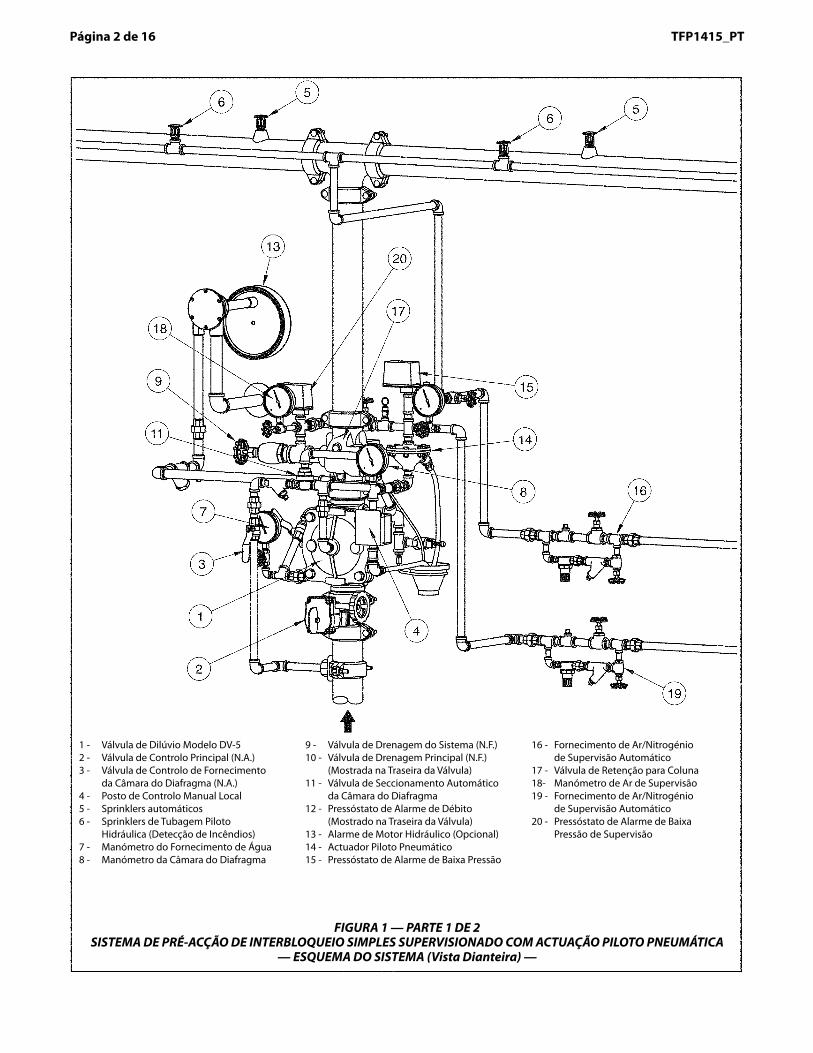
FIGURA 1 — PARTE 1 DE 2SISTEMA DE PRÉ-ACÇÃO DE INTERBLOQUEIO SIMPLES SUPERVISIONADO COM ACTUAÇÃO PILOTO PNEUMÁTICA
— ESQUEMA DO SISTEMA (Vista Dianteira) —
1 - Válvula de Dilúvio Modelo DV-52 - Válvula de Controlo Principal (N.A.)3 - Válvula de Controlo de Fornecimento
da Câmara do Diafragma (N.A.)4 - Posto de Controlo Manual Local5 - Sprinklers automáticos6 - Sprinklers de Tubagem Piloto
Hidráulica (Detecção de Incêndios) 7 - Manómetro do Fornecimento de Água8 - Manómetro da Câmara do Diafragma
9 - Válvula de Drenagem do Sistema (N.F.)10 - Válvula de Drenagem Principal (N.F.)
(Mostrada na Traseira da Válvula)11 - Válvula de Seccionamento Automático
da Câmara do Diafragma 12 - Pressóstato de Alarme de Débito
(Mostrado na Traseira da Válvula)13 - Alarme de Motor Hidráulico (Opcional)14 - Actuador Piloto Pneumático 15 - Pressóstato de Alarme de Baixa Pressão
16 - Fornecimento de Ar/Nitrogénio de Supervisão Automático
17 - Válvula de Retenção para Coluna18- Manómetro de Ar de Supervisão19 - Fornecimento de Ar/Nitrogénio
de Supervisão Automático20 - Pressóstato de Alarme de Baixa
Pressão de Supervisão

Page 3 of 16TFP1415TFP1415_PT Página � de 16
FIGURA 1 — PARTE 2 DE 2SISTEMA DE PRÉ-ACÇÃO DE INTERBLOQUEIO SIMPLES SUPERVISIONADO COM ACTUAÇÃO PILOTO PNEUMÁTICA
— ESQUEMA DO SISTEMA (Vista Traseira) —
1 - Válvula de Dilúvio Modelo DV-52 - Válvula de Controlo Principal (N.A.)3 - Válvula de Controlo de Fornecimento
da Câmara do Diafragma (N.A.)4 - Posto de Controlo Manual Local
(Mostrado na Dianteira da Válvula)5 - Sprinklers automáticos6 - Sprinklers de Tubagem Piloto
Hidráulica (Detecção de Incêndios)7 - Manómetro do Fornecimento de Água
(Mostrado na Dianteira da Válvula)
8 - Manómetro da Câmara do Diafragma (Mostrado na Dianteira da Válvula)
9 - Válvula de Drenagem do Sistema (N.F.)10 - Válvula de Drenagem Principal (N.F.)11 - Válvula de Seccionamento Automático
da Câmara do Diafragma12 - Pressóstato de Alarme de Débito 13 - Alarme de Motor Hidráulico (Opcional)14 - Actuador Piloto Pneumático 15 - Pressóstato de Alarme de Baixa Pressão
16 - Fornecimento de Ar/Nitrogénio de Supervisão Automático
17 - Válvula de Retenção para Coluna18 - Manómetro de Ar de Supervisão
(Mostrado na Dianteira da Válvula)19 - Fornecimento de Ar/Nitrogénio
de Supervisão Automático20 - Pressóstato de Alarme de Baixa
Pressão de Supervisão
Page 4 of 16 TFP1415
Nº DESCRIÇÃO QTD P/N1 Manómetro de Água 20 bar/
300 psi . . . . . . . . . . . . . . . . . . . . . . . . . 2 92-343-1-0052 Válvula de Teste do Manómetro 1/4” 1 46-005-1-0023 Posto de Controlo Manual Mode-
lo MC-1 . . . . . . . . . . . . . . . . . . . . . . . . 1 52-289-2-0014 Válvula de Drenagem Automática
Modelo AD-1 . . . . . . . . . . . . . . . . . . . 1 52-793-2-0045 Válvula de Seccionamento Auto-
mático Modelo ASV-1. . . . . . . . . . . 1 92-343-1-0216 Pressóstato de Alarme de Débito
(PS10-2A) . . . . . . . . . . . . . . . . . . . . . . 1 25717 Válvula de Esfera 1/2” . . . . . . . . . . . 2 46-050-1-0048 Válvula de Retenção com Mola 1/2” 1 92-322-1-0029 Filtro Y 1/2”. . . . . . . . . . . . . . . . . . . . . 1 52-353-1-005
10 Válvula de Retenção de Batente 3/4” 1 46-049-1-00511 Válvula em Ângulo 3/4” . . . . . . . . . 1 46-048-1-00512 Funil de drenagem . . . . . . . . . . . . . 1 92-211-1-00513 Suporte do Funil de Drenagem . 1 92-211-1-00314 Funil de Drenagem . . . . . . . . . . . . . 1 92-343-1-00715 Elemento de Purga 3/32”. . . . . . . . 1 92-032-1-00216 Tubagem 1/4” x 18” . . . . . . . . . . . . . 1 CH17 Colector 1/2” . . . . . . . . . . . . . . . . . . . 1 CH18 Tubagem 1/2” x 12” . . . . . . . . . . . . . 1 CH19 Tampão 1/4”. . . . . . . . . . . . . . . . . . . . 1 CH20 Tampão 3/4”. . . . . . . . . . . . . . . . . . . . 1 CH21 União 1/2”. . . . . . . . . . . . . . . . . . . . . . 5 CH22 União 3/4”. . . . . . . . . . . . . . . . . . . . . . 1 CH23 Cotovelo1/4” 90° . . . . . . . . . . . . . . . 1 CH24 Cotovelo1/2” 90° . . . . . . . . . . . . . . . 7 CH25 Cotovelo3/4” 90° . . . . . . . . . . . . . . . 1 CH26 Cotovelo3/4” x 1/2” 90° . . . . . . . . . 1 CH27 União T 1/2” . . . . . . . . . . . . . . . . . . . . 3 CH28 União T 1/2” x 1/4” x 1/2” . . . . . . . . 3 CH
Nº DESCRIÇÃO QTD P/N29 União T 3/4” . . . . . . . . . . . . . . . . . . . . 1 CH30 União T 3/4” x 1/2” x 3/4” . . . . . . . . 2 CH31 Vedante de União Roscada 1/4” . 2 CH32 Vedante de União Roscada 1/2” . 3 CH33 União Roscada 1/2” x 1-1/2” . . . . . 11 CH34 União Roscada 1/2” x 2” . . . . . . . . . 1 CH35 União Roscada 1/2” x 2-1/2” . . . . . 3 CH36 União Roscada 1/2” x 5” . . . . . . . . . 2 CH37 União Roscada 1/2” x 7” . . . . . . . . . 1 CH38 Seleccionar União Rosc. pela tab. 2 CH39 Seleccionar União Rosc. pela tab. 2 CH40 União Roscada 3/4” x 1-1/2” . . . . . 1 CH41 União Roscada 3/4” x 2” . . . . . . . . . 1 CH42 União Roscada 3/4” x 4” . . . . . . . . . 1 CHP1 Manómetro de Ar 17,5 bar/
250 psi . . . . . . . . . . . . . . . . . . . . . . . . . 1 92-343-1-012P2 Válvula de Teste do Manómetro 1/4” 1 46-005-1-002P3 Pressóstato de Alarme de Baixa
Pressão (PS10-2A) . . . . . . . . . . . . . . 1 2571P4 Válvula de alívio de pressão 1/4” 1 92-343-1-019P5 Válvula de Retenção de Batente 1/2” 1 46-049-1-004P6 Válvula de Globo 1/2”. . . . . . . . . . . 1 46-047-1-004P7 Válvula em Ângulo 3/4” . . . . . . . . . 1 46-048-1-007P8 Tampão 1/4”. . . . . . . . . . . . . . . . . . . . 3 CHP9 Redução Macho-Fêmea 1/2” x 1/4”1 CH
P10 União 1/2”. . . . . . . . . . . . . . . . . . . . . . 1 CHP11 Cotovelo1/2” 90° . . . . . . . . . . . . . . . 1 CHP12 Cruzeta 1/2” . . . . . . . . . . . . . . . . . . . . 1 CHP13 União T 1/2” x 1/2” x 1/4” . . . . . . . . 1 CHP14 União T 1” x 3/4” x 1/2” . . . . . . . . . . 1 CHP15 União Roscada 1/4” x 3” . . . . . . . . . 1 CHP16 União Roscada 1/2” x 1-1/2” . . . . . 5 CH
Nº DESCRIÇÃO QTD P/NP17 União Roscada 1/2” x 2-1/2” . . . . . 1 CHP18 União Roscada 3/4” x 1-1/2” . . . . . 1 CHP19 União Roscada 1” x 2” . . . . . . . . . . . 1 CHD1 Manómetro de Ar 17,5 bar/
250 psi . . . . . . . . . . . . . . . . . . . . . . . . . 1 92-343-1-012D2 Válvula de Teste do Manómetro 1/4” 1 46-005-1-002D3 Actuador Piloto Pneumático
Modelo DP-1 . . . . . . . . . . . . . . . . . . . 1 52-280-1-001D4 Pressóstato de Alarme de Baixa
Pressão (PS40-2A) . . . . . . . . . . . . . . 1 2753D5 Válvula de Globo 1/2”. . . . . . . . . . . 1 46-047-1-004D6 Válvula de alívio de pressão 1/4” 1 92-343-1-020D7 Colector 1/2” . . . . . . . . . . . . . . . . . . . 1 CHD8 Tubagem 1/2” x 24” . . . . . . . . . . . . . 1 CHD9 Tampão 1/4”. . . . . . . . . . . . . . . . . . . . 1 CH
D10 Cotovelo1/2” 45° 1 CHD11 Cotovelo1/2” 45° 1 CHD12 União T 1/2” x 1/2” x 1/4” . . . . . . . . 2 CHD13 União T 1/2” . . . . . . . . . . . . . . . . . . . . 2 CHD14 União Roscada 1/4” x 1-1/2” . . . . . 1 CHD15 União Roscada 1/2” x 1-1/2” . . . . . 6 CHD16 União Roscada 1/2” x 2” . . . . . . . . . 1 CHD17 União Roscada 1/2” x 3” . . . . . . . . . 1 CH
Nº União Roscada
Seleccionar Tamanho União Roscada por Tamanho Válvula Dilúvio DV-5
DN40(1-1/2”)
DN50(2”)
38 vedante 1/2” 1/2” x 2“39 1/2” x 5” 1/2” x 5-1/2”
Página 4 de 16 TFP1415_PT
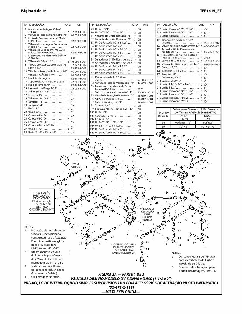
FIGURA 2A — PARTE 1 DE 3VÁLVULAS DILÚVIO MODELO DV-5 DN40 e DN50 (1-1/2 e 2”)
PRÉ-ACÇÃO DE INTERBLOQUEIO SIMPLES SUPERVISIONADO COM ACESSÓRIOS DE ACTUAÇÃO PILOTO PNEUMÁTICA (52-478-X-118)
—VISTA EXPLODIDA—
NOTAS:1. Pré-acção de Interbloqueio
Simples Supervisionado com Acessórios de Actuação Piloto Pneumática engloba Itens 1-42 mais Itens P1-P19 e Itens D1-D17.
2. Utilize apenas a Válvula de Retenção para Coluna de 2” Modelo CV-1FR para montagens de 1-1/2” ou 2”.
3. Todas as Juntas e Uniões Roscadas são galvanizadas (Encomenda Padrão).
4. CH: Ferragens Normais.
LOCALIZAÇÃO PARA VÁLVULA DE CONTROLO
DE ALARME N.A. DE SUPERVISÃO
ELÉCTRICA OPCIONAL (BVS-3/4”)
MOSTRADA VÁLVULA DILÚVIO MODELO DV-5 RANHURA x
RANHURA DN50 (2”)
(TOM VERDE)
NOTAS:5. Consulte Figura 2 de TFP1305
para identificação do Orifício da Válvula de Dilúvio.
6. Oriente toda a Tubagem para o Funil de Drenagem, Item 14.
VÁLVULA DE RETENÇÃO
PARA COLUNA (NOTA 2)
TFP1415
Nº DESCRIÇÃO QTD P/N1 Manómetro de Água 20 bar/
300 psi . . . . . . . . . . . . . . . . . . . . . . . . . . 2 92-343-1-0052 Válvula de Teste do Manómetro 1/4”1 46-005-1-0023 Posto de Controlo Manual Modelo
MC-1 . . . . . . . . . . . . . . . . . . . . . . . . . . . . 1 52-289-2-0014 Válvula de Drenagem Automática
Modelo AD-1 1 52-793-2-0045 Válvula de Seccionamento Auto-
mático Modelo ASV-1. . . . . . . . . . . . 1 92-343-1-0216 Pressóstato de Alarme de Débito
(PS10-2A) . . . . . . . . . . . . . . . . . . . . . . . 1 25717 Válvula de Esfera 1/2” . . . . . . . . . . . . 2 46-050-1-0048 Válvula de Retenção com Mola 1/2” 1 92-322-1-0029 Filtro Y 1/2”. . . . . . . . . . . . . . . . . . . . . . 1 52-353-1-005
10 Válvula de Retenção de Batente 3/4”1 46-049-1-00511 Válvula em Ângulo 1-1/4” . . . . . . . . 1 46-048-1-00712 Funil de drenagem . . . . . . . . . . . . . . 1 92-211-1-00513 Suporte do Funil de Drenagem . 1 92-211-1-00314 Funil de Drenagem . . . . . . . . . . . . . 1 92-343-1-00715 Elemento de Purga 3/32”. . . . . . . . 1 92-032-1-00216 Tubagem 1/4” x 18” . . . . . . . . . . . . . 1 CH17 Colector 1/2” . . . . . . . . . . . . . . . . . . . 1 CH18 Tubagem 1/2” x 18” . . . . . . . . . . . . . 1 CH19 Tampão 1/4”. . . . . . . . . . . . . . . . . . . . 1 CH20 Tampão 3/4”. . . . . . . . . . . . . . . . . . . . 1 CH21 União 1/2”. . . . . . . . . . . . . . . . . . . . . . 5 CH22 União 3/4”. . . . . . . . . . . . . . . . . . . . . . 1 CH23 Cotovelo1/4” 90° . . . . . . . . . . . . . . . 1 CH24 Cotovelo1/2” 90° . . . . . . . . . . . . . . . 7 CH25 Cotovelo3/4” x 1/2” 90° . . . . . . . . . 1 CH26 Cotovelo1-1/4” 90°. . . . . . . . . . . . . . 1 CH
Nº DESCRIÇÃO QTD P/N27 União T 1/2” . . . . . . . . . . . . . . . . . . . . 3 CH28 União T 1/2” x 1/4” x 1/2” . . . . . . . . 3 CH29 União T 3/4” . . . . . . . . . . . . . . . . . . . . 1 CH30 União T 3/4” x 1/2” x 3/4” . . . . . . . . 2 CH31 Vedante de União Roscada 1/4” . 2 CH32 Vedante de União Roscada 1/2” . 2 CH33 União Roscada 1/2” x 1-1/2” . . . . . 13 CH34 União Roscada 1/2” x 2-1/2” . . . . . 1 CH35 União Roscada 1/2” x 3-1/2” . . . . . 1 CH36 União Roscada 1/2” x 4” . . . . . . . . . 1 CH37 União Roscada 1/2” x 4-1/2” . . . . . 1 CH38 União Roscada 1/2” x 5” . . . . . . . . . 1 CH39 União Roscada 1/2” x 5-1/2” . . . . . 1 CH40 União Roscada 1/2” x 7” . . . . . . . . . 2 CH41 União Roscada 3/4” x 1-1/2” . . . . . 5 CH42 União Roscada 3/4” x 2” . . . . . . . . . 1 CH43 União Roscada 1-1/4” x 2” . . . . . . . 6 CH44 União Roscada 1-1/4” x 4” . . . . . . . 1 CHP1 Manómetro de Ar 17,5 bar/250 psi 1 92-343-1-012P2 Válvula de Teste do Manómetro 1/4”1 46-005-1-002P3 Pressóstato de Alarme de Baixa
Pressão (PS10-2A) . . . . . . . . . . . . . . 1 2571P4 Válvula de alívio de pressão 1/4” 1 92-343-1-019P5 Válvula de Retenção de Batente 1/2” 1 46-049-1-004P6 Válvula de Globo 1/2”. . . . . . . . . . . 1 46-047-1-004P7 Válvula em Ângulo 1-1/4” . . . . . . . 1 46-048-1-007P8 Tampão 1/4”. . . . . . . . . . . . . . . . . . . . 3 CHP9 Redução Macho-Fêmea 1/2” x 1/4” 1 CH
P10 União 1/2”. . . . . . . . . . . . . . . . . . . . . . 1 CH
Nº DESCRIÇÃO QTD P/NP11 Cotovelo1/2” 90° . . . . . . . . . . . . . . . 1 CHP12 Cruzeta 1/2” . . . . . . . . . . . . . . . . . . . . 1 CHP13 União T 1/2” x 1/2” x 1/4” . . . . . . . . 1 CHP14 União T 1-1/4” x 1-1/4” x 1/2” . . . . 1 CHP15 União Roscada 1/4” x 3” . . . . . . . . . 1 CHP16 União Roscada 1/2” x 1-1/2” . . . . . 6 CHP17 União Roscada 1-1/4” x 2” . . . . . . . 1 CHP18 União Roscada 1-1/4” x 3” . . . . . . . 1 CHD1 Manómetro de Ar 17,5 bar/250 psi 1 92-343-1-012D2 Válvula de Teste do Manómetro
1/4” . . . . . . . . . . . . . . . . . . . . . . . . . . . . 1 46-005-1-002D3 Actuador Piloto Pneumático
Modelo DP-1 . . . . . . . . . . . . . . . . . . . 1 52-280-1-001D4 Pressóstato de Alarme de Baixa
Pressão. . . . . . . . . . . . . . . . . . . . . . . . . 1 2573D5 Válvula de Globo 1/2”. . . . . . . . . . . 1 46-047-1-004D6 Válvula de alívio de pressão 1/4” 1 92-343-1-020D7 Colector 1/2” . . . . . . . . . . . . . . . . . . . 1 CHD8 Tubagem 1/2” x 24” . . . . . . . . . . . . . 1 CHD9 Tampão 1/4”. . . . . . . . . . . . . . . . . . . . 1 CH
D10 Cotovelo1/2" 45° . . . . . . . . . . . . . . . 1 CHD11 Cotovelo1/2" 90° . . . . . . . . . . . . . . . 1 CHD12 União T 1/2” x 1/2” x 1/4” . . . . . . . . 2 CHD13 União T 1/2” . . . . . . . . . . . . . . . . . . . . 2 CHD14 União Roscada 1/4” x 1-1/2” . . . . . 1 CHD15 União Roscada 1/2” x 1-1/2” . . . . . 6 CHD16 União Roscada 1/2” x 2” . . . . . . . . . 1 CHD17 União Roscada 1/2” x 3” . . . . . . . . . 1 CH
Página 5 de 16 TFP1415_PTTFP1415_PT Página 5 de 16
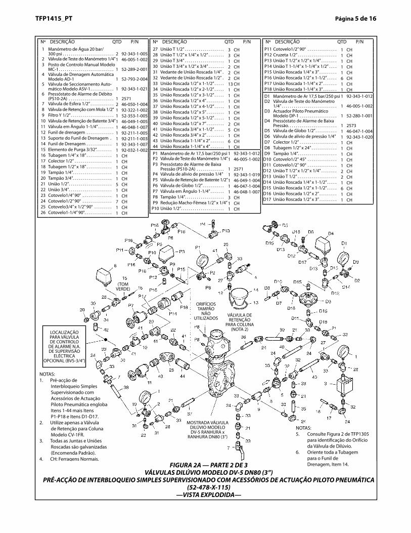
NOTAS:1. Pré-acção de
Interbloqueio Simples Supervisionado com Acessórios de Actuação Piloto Pneumática engloba Itens 1-44 mais Itens P1-P18 e Itens D1-D17.
2. Utilize apenas a Válvula de Retenção para Coluna Modelo CV-1FR.
3. Todas as Juntas e Uniões Roscadas são galvanizadas (Encomenda Padrão).
4. CH: Ferragens Normais.
LOCALIZAÇÃO PARA VÁLVULA DE CONTROLO
DE ALARME N.A. DE SUPERVISÃO
ELÉCTRICA OPCIONAL (BVS-3/4”)
MOSTRADA VÁLVULA DILÚVIO MODELO DV-5 RANHURA x
RANHURA DN80 (3”)
(TOM VERDE)
ORIFÍCIOS TAMPÃO
NÃO UTILIZADOS
FIGURA 2A — PARTE 2 DE 3VÁLVULAS DILÚVIO MODELO DV-5 DN80 (3”)
PRÉ-ACÇÃO DE INTERBLOQUEIO SIMPLES SUPERVISIONADO COM ACESSÓRIOS DE ACTUAÇÃO PILOTO PNEUMÁTICA (52-478-X-115)
—VISTA EXPLODIDA—
NOTAS:5. Consulte Figura 2 de TFP1305
para identificação do Orifício da Válvula de Dilúvio.
6. Oriente toda a Tubagem para o Funil de Drenagem, Item 14.
VÁLVULA DE RETENÇÃO
PARA COLUNA (NOTA 2)
Page 6 of 16 TFP1415
Nº DESCRIÇÃO QTD P/N1 Manómetro de Água 20 bar/
300 psi . . . . . . . . . . . . . . . . . . . . . . . . . 2 92-343-1-0052 Válvula de Teste do Manómetro 1/4” 1 46-005-1-0023 Posto de Controlo Manual Mode-
lo MC-1 . . . . . . . . . . . . . . . . . . . . . . . . 1 52-289-2-0014 Válvula de Drenagem Automática
Modelo AD-1 . . . . . . . . . . . . . . . . . . . 1 52-793-2-0045 Válvula de Seccionamento Auto-
mático Modelo ASV-1. . . . . . . . . . . 1 92-343-1-0216 Pressóstato de Alarme de Débito
(PS10-2A) . . . . . . . . . . . . . . . . . . . . . . 1 25717 Válvula de Esfera 1/2” . . . . . . . . . . . 2 46-050-1-0048 Válvula de Retenção com Mola 1/2” 1 92-322-1-0029 Filtro Y 1/2”. . . . . . . . . . . . . . . . . . . . . 1 52-353-1-005
10 Válvula de Retenção de Batente 3/4” 1 46-049-1-00511 Não utilizada . . . . . . . . . . . . . . . . . . . 0 N/D12 Válvula em Ângulo 2” . . . . . . . . . . . 1 46-048-1-00913 Funil de drenagem . . . . . . . . . . . . . 1 92-211-1-00514 Suporte do Funil de Drenagem . 1 92-211-1-00315 Funil de Drenagem . . . . . . . . . . . . . 1 92-343-1-00716 Elemento de Purga 3/32”. . . . . . . . 1 92-032-1-00217 Tubagem 1/4” x 24” 1 CH18 Colector 1/2” . . . . . . . . . . . . . . . . . . . 1 CH19 Tubagem 1/2” x 24” . . . . . . . . . . . . . 1 CH20 Tampão 1/4”. . . . . . . . . . . . . . . . . . . . 1 CH21 Tampão 3/4”. . . . . . . . . . . . . . . . . . . . 1 CH22 União 1/2”. . . . . . . . . . . . . . . . . . . . . . 5 CH23 União 1”. . . . . . . . . . . . . . . . . . . . . . . . 1 CH24 Cotovelo1/4” 90° . . . . . . . . . . . . . . . 1 CH25 Cotovelo1/2” 90° . . . . . . . . . . . . . . . 7 CH26 União T 1/2” . . . . . . . . . . . . . . . . . . . . 3 CH27 União T 1/2” x 1/4” x 1/2” . . . . . . . . 3 CH28 União T 3/4” x 1/2” x 3/4” . . . . . . . . 2 CH29 Cotovelo1” x 1/2” 90°. . . . . . . . . . . . 1 CH30 União T 1” x 3/4” x 1” . . . . . . . . . . . . 1 CH31 Cotovelo2” 90°. . . . . . . . . . . . . . . . . . 1 CH32 Vedante de União Roscada 1/4” . 2 CH
Nº DESCRIÇÃO QTD P/N33 Vedante de União Roscada 1/2” 2 CH34 União Roscada 1/2” x 1-1/2” . . . . . 10 CH35 União Roscada 1/2” x 2-1/2” . . . . . 2 CH36 União Roscada 1/2” x 3” . . . . . . . . . 1 CH37 União Roscada 1/2” x 5” . . . . . . . . . 2 CH38 União Roscada 1/2” x 6” . . . . . . . . . 1 CH39 União Roscada 1/2” x 7” . . . . . . . . . 2 CH40 Seleccionar União Rosc. pela tab. 2 CH41 Seleccionar União Rosc. pela tab. 2 CH42 Seleccionar União Rosc. pela tab. 2 CH43 União Roscada 3/4” x 1-1/2” . . . . . 1 CH44 União Roscada 3/4” x 2” . . . . . . . . . 1 CH45 Seleccionar União Rosc. pela tab. 2 CH46 União Roscada 1” vedante . . . . . . 2 CH47 União Roscada 1” x 3” . . . . . . . . . . . 1 CH48 Não utilizada . . . . . . . . . . . . . . . . . . . 0 N/D49 União Roscada 2” x 3” . . . . . . . . . . . 2 CH
P1 Manómetro de Ar 17,5 bar/250 psi . . . . . . . . . . . . . . . . . . . . . . . . . 1 92-343-1-012
P2 Válvula de Teste do Manómetro 1/4” 1 46-005-1-002P3 Pressóstato de Alarme de Baixa
Pressão (PS10-2A) . . . . . . . . . . . . . . 1 2571P4 Válvula de alívio de pressão 1/4” 1 92-343-1-019P5 Válvula de Retenção de Batente 1/2” 1 46-049-1-004P6 Válvula de Globo 1/2”. . . . . . . . . . . 1 46-047-1-004P7 Válvula em Ângulo 2” . . . . . . . . . . . 1 46-048-1-009P8 Tampão 1/4”. . . . . . . . . . . . . . . . . . . . 3 CHP9 Redução Macho-Fêmea 1/2” x 1/4”1 CH
P10 União 1/2”. . . . . . . . . . . . . . . . . . . . . . 1 CHP11 Cotovelo1/2” 90° . . . . . . . . . . . . . . . 1 CHP12 Cruzeta 1/2” . . . . . . . . . . . . . . . . . . . . 1 CHP13 União T 1/2” x 1/2” x 1/4” . . . . . . . . 1 CH
Nº DESCRIÇÃO QTD P/NP14 União T 2” x 2” x 1/2” . . . . . . . . . . . . 1 CHP15 União Roscada 1/4” x 3” . . . . . . . . . 1 CHP16 União Roscada 1/2” x 1-1/2” . . . . . 6 CHP17 União Roscada 2” x 3” . . . . . . . . . . . 2 CHD1 Manómetro de Ar 17,5 bar/
250 psi . . . . . . . . . . . . . . . . . . . . . . . . . 1 92-343-1-012D2 Válvula de Teste do Manómetro 1/4” 1 46-005-1-002D3 Actuador Piloto Pneumático
Modelo DP-1 . . . . . . . . . . . . . . . . . . . 1 52-280-1-001D4 Pressóstato de Alarme de Baixa
Pressão (PS40-2A) . . . . . . . . . . . . . . 1 2573D5 Válvula de Globo 1/2”. . . . . . . . . . . 1 46-047-1-004D6 Válvula de alívio de pressão 1/4” 1 92-343-1-020D7 Colector 1/2” . . . . . . . . . . . . . . . . . . . 1 CHD8 Tubagem 1/2” x 24” . . . . . . . . . . . . . 1 CHD9 Tampão 1/4”. . . . . . . . . . . . . . . . . . . . 1 CH
D10 Cotovelo1/2" 45° . . . . . . . . . . . . . . . 1 CHD11 Cotovelo1/2" 90° . . . . . . . . . . . . . . . 1 CHD12 União T 1/2” x 1/2” x 1/4” . . . . . . . . 2 CHD13 União T 1/2” . . . . . . . . . . . . . . . . . . . . 2 CHD14 União Roscada 1/4” x 1-1/2” . . . . . 1 CHD15 União Roscada 1/2” x 1-1/2” . . . . . 6 CHD16 União Roscada 1/2” x 2” . . . . . . . . . 1 CHD17 União Roscada 1/2” x 3” . . . . . . . . . 1 CH
Nº União Roscada
Seleccionar Tamanho União Roscada por Tamanho Válvula Dilúvio DV-5
DN100(4”)
DN150(6”)
DN200(8”)
40 1/2” x 2-1/2” 1/2” x 5-1/2” 1/2” x 8-1/2”41 1/2” x 2“ 1/2” x 3” 1/2” x 3-1/2”42 1/2” x 6-1/2” 1/2” x 7-1/2” 1/2” x 9”45 3/4” x 2-1/2” 3/4” x 3-1/2” 3/4” x 4-1/2”
Página 6 de 16 TFP1415_PT
LOCALIZAÇÃO PARA VÁLVULA DE CONTROLO
DE ALARME N.A. DE SUPERVISÃO
ELÉCTRICA OPCIONAL (BVS-3/4”)
MOSTRADA VÁLVULA DILÚVIO
MODELO DV-5 FLANGE x RANHURA
DN100 (4”)
(TOM VERDE)
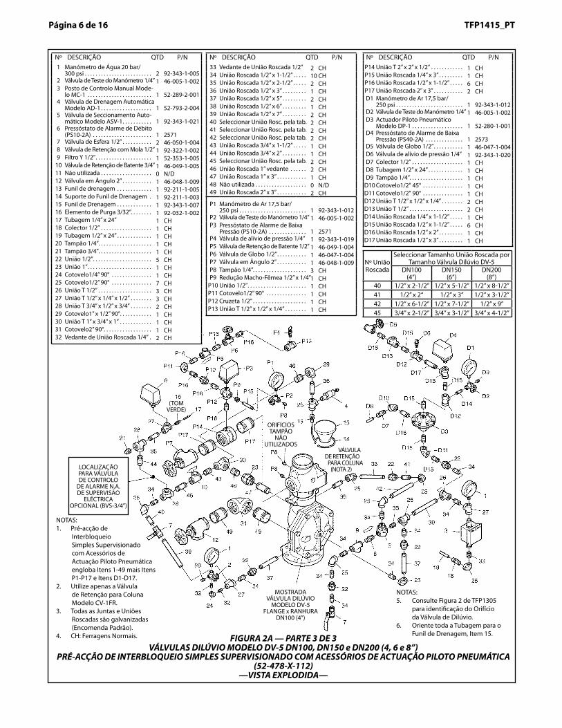
FIGURA 2A — PARTE 3 DE 3VÁLVULAS DILÚVIO MODELO DV-5 DN100, DN150 e DN200 (4, 6 e 8”)
PRÉ-ACÇÃO DE INTERBLOQUEIO SIMPLES SUPERVISIONADO COM ACESSÓRIOS DE ACTUAÇÃO PILOTO PNEUMÁTICA (52-478-X-112)
—VISTA EXPLODIDA—
NOTAS:5. Consulte Figura 2 de TFP1305
para identificação do Orifício da Válvula de Dilúvio.
6. Oriente toda a Tubagem para o Funil de Drenagem, Item 15.
ORIFÍCIOS TAMPÃO
NÃO UTILIZADOS
VÁLVULA DE RETENÇÃO
PARA COLUNA (NOTA 2)
NOTAS:1. Pré-acção de
Interbloqueio Simples Supervisionado com Acessórios de Actuação Piloto Pneumática engloba Itens 1-49 mais Itens P1-P17 e Itens D1-D17.
2. Utilize apenas a Válvula de Retenção para Coluna Modelo CV-1FR.
3. Todas as Juntas e Uniões Roscadas são galvanizadas (Encomenda Padrão).
4. CH: Ferragens Normais.
Page 7 of 16TFP1415Página � de 16 TFP1415_PTTFP1415_PT Página � de 16
Nº União Roscada
Seleccionar Tamanho União Roscada por Tamanho Válvula Dilúvio DV-5
DN40 (1-1/2”) DN50 (2”) DN80 (3”) DN100 (4”) DN150 (6”) DN200 (8”)1 vedante 1/2” 1/2” x 2“ 1/2” x 1-1/2” 1/2” x 2-1/2” 1/2” x 5-1/2” 1/2” x 8-1/2”2 vedante 1/2” vedante 1/2” 1/2” x 1-1/2” 1/2” x 2“ 1/2” x 3” 1/2” x 3-1/2”3 1/2” x 5” 1/2” x 5-1/2” 1/2” x 7” 1/2” x 6-1/2” 1/2” x 7-1/2” 1/2” x 9”4 3/4” x 1-1/2” 3/4” x 1-1/2” 3/4” x 1-1/2” 3/4” x 2-1/2” 3/4” x 3-1/2” 3/4” x 4-1/2”
Tamanho Dreno Princi-pal Sistema
3/4” NPT 3/4” NPT 1-1/4” NPT 2” NPT 2” NPT 2” NPT
Tamanho Dreno Prin-
cipal3/4” NPT 3/4” NPT 1-1/4” NPT 2” NPT 2” NPT 2” NPT
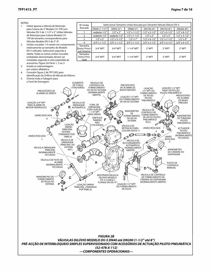
FIGURA 2BVÁLVULAS DILÚVIO MODELO DV-5 DN40 até DN200 (1-1/2” até 8”)
PRÉ-ACÇÃO DE INTERBLOQUEIO SIMPLES SUPERVISIONADO COM ACESSÓRIOS DE ACTUAÇÃO PILOTO PNEUMÁTICA (52-478-X-112)
—COMPONENTES OPERACIONAIS—
PRESSÓSTATO DE ALARME DE DÉBITO
MOSTRADA VÁLVULA DILÚVIO MODELO
DV-5 FLANGE x FLANGE DN100 (4”)
VÁLVULA DE CONTROLO DE
FORNECIMENTO DE AR DO SISTEMA
(NORMALMENTE ABERTA)
VÁLVULA DE DRENAGEM
AUTOMÁTICA
UNIÃO ROSCADA
UNIÃO ROSCADA
LIGAÇÃO 3/4” NPT PARA ALARME DE
MOTOR HIDRÁULICO
UNIÃO ROSCADA
MANÓMETRO DA CÂMARA DO DIAFRAGMA
POSTO DE CONTROLO MANUAL
VÁLVULA DE SECCIONAMENTO
AUTOMÁTICO (NORMALMENTE
ABERTA)
LIGAÇÃO 1/2” NPT DO FORNECIMENTO
DE ÁGUA
FUNIL DE DRENAGEM
COM LIGAÇÃO 1-1/4” NPT
PARA DRENOORIFÍCIOS TAMPÃO
NÃO UTILIZADOSLIGAÇÃO
DRENO PRINCIPAL
SISTEMA (TAMANHO POR
TABELA)
VÁLVULA DRENAGEM PRINCIPAL
(NORMALMENTE FECHADA)
VÁLVULA DE TESTE DE ALARME
(NORMALMENTE FECHADA)
MANÓMETRO DO FORNECIMENTO
DE ÁGUA DO SISTEMA LIGAÇÃO DRENO
PRINCIPAL (TAMANHO POR TABELA)
VÁLVULA DE CONTROLO DE FORNECIMENTO DA
CÂMARA DO DIAFRAGMA (NORMALMENTE ABERTA)
NOTAS:1. Utilize apenas a Válvula de Retenção
para Coluna de 2” Modelo CV-1FR com Válvulas DV-5 de 1-1/2” e 2”. Utilize Válvulas de Retenção para Coluna Modelo CV-1FR de tamanho correspondente para Válvulas Modelo DV-5 de 3”-8”.
2. Uniões roscadas 1-4 variam em comprimento relativamente ao tamanho do Modelo DV-5 utilizado. Seleccione segundo a tabela. Todas as outras uniões roscadas embaladas desmontadas devem ser instaladas segundo a vista explodida de acessórios, Figura 2A Parte 1, 2 ou 3.
3. Instale as submontagens por ordem alfabética.
4. Consulte Figura 2 de TFP1305 para identificação do Orifício da Válvula de Dilúvio.
5. Oriente toda a Tubagem para o Funil de Drenagem.
LIGAÇÃO 1/2” NPT DO
FORNECIMENTO DE AR DO
PILOTO PNEUMÁTICO
UNIÃO ROSCADA
PRESSÓSTATO DE ALARME DE BAIXA PRESSÃO
VÁLVULA DE RETENÇÃO PARA COLUNA (NOTA 1)
MANÓMETRO DE
FORNECIMENTO DE AR DO SISTEMA
LIGAÇÃO 1/2” NPT DO FORNECIMENTO DE AR DO SISTEMA
VÁLVULA DE DRENAGEM
PRINCIPAL DO SISTEMA
(N.F.)
VÁLVULA DE CONTROLO DE FORNECIMENTO
DE AR DO PILOTO PNEUMÁTICO
(N.A.)
MANÓMETRO DE TUBAGEM
PILOTO PNEUMÁTICA
ACTUADOR PILOTO
PNEUMÁTICO (NORMALMENTE
FECHADO)
PRESSÓSTATO DE ALARME
DE BAIXA PRESSÃO
LIGAÇÃO 1/2” NPT PARA “DETECÇÃO
PILOTO PNEUMÁTICA”
ELEMENTO DE PURGA
(TOM VERDE)
Page 8 of 16 TFP1415
FIGURE 31-1/2 thru 8 INCH (DN40 thru DN200) MODEL DV-5 DELUGE VALVES
SUPERVISED SINGLE INTERLOCK PREACTION WITH DRY PILOT ACTUATION TRIM— NOMINAL INSTALLATION DIMENSIONS —
(800,1)31.50
(830,3)32.69
CHAMBER SUPPLYCONNECTING TRIM
(FIELD FABRICATED)
MAINCONTROL
VALVE
A
2" NPSDRAIN
DIAPHRAGM
L
1/2" NPS
G
H KJ
LEFT VIEW FRONT VIEW
*
1-1/4" NPSDRAIN
B
F
M
MINIMUM CLEARANCE.*
(635,0)25.00
(627,1)24.69
(723,9)28.50
E*
D*C*
(933,5)36.75
(231,8)9.13
(266,7)10.50
(152,4)6.00
(152,4)6.00
(390,5)15.38
(DN50)2"
(79,4)3.13
(177,8)7.00
(225,4)8.88
(330,2)13.00
(266,7)10.50
(147,6)5.81
(147,6)5.81
(76,2)3.00
(101,6)4.00
(376,2)14.81
(DN40)1-1/2"
(101,6)4.00
(177,8)7.00
(181,0)7.13
(330,2)13.00
(76,2)3.00
(177,8)7.00
(79,4)3.13
(254,0)10.00
(289,0)11.38
(298,5)11.75
(363,5)14.31
(454,0)17.88
(476,3)18.75
(266,7)10.50
(165,1)6.50
(200,0)7.88
(217,5)8.56
(252,4)9.94
(158,8)6.25
(181,0)7.13
(9,5)0.38
(39,7)1.56
(644,5)25.38
(752,5)29.63
(44,5)1.75
(88,9)3.50
(266,7)10.50
(181,0)7.13
(198,4)7.81
(265,1)10.44
(266,7)10.50
(170,0)6.69
(108,0)4.25
(536,6)21.13
(DN80)3"
(368,3)14.50
(42,9)1.69
(177,8)7.00
A B C D E G H J K L MFNominal Installation Dimensions in Inches and (mm)
SizeValve
(170,0)6.69
(6,4)0.25
(DN100)4"
(DN150)6"
(158,8)6.25
(304,8)12.00
(406,4)16.00
(539,8)21.25
(273,1)10.75
(269,9)10.63
(927,1)36.50
(DN200)8"
(44,5)1.75
(266,7)10.50
(158,8)6.25
(181,0)7.13
(181,0)7.13
Página � de 16 TFP1415_PT
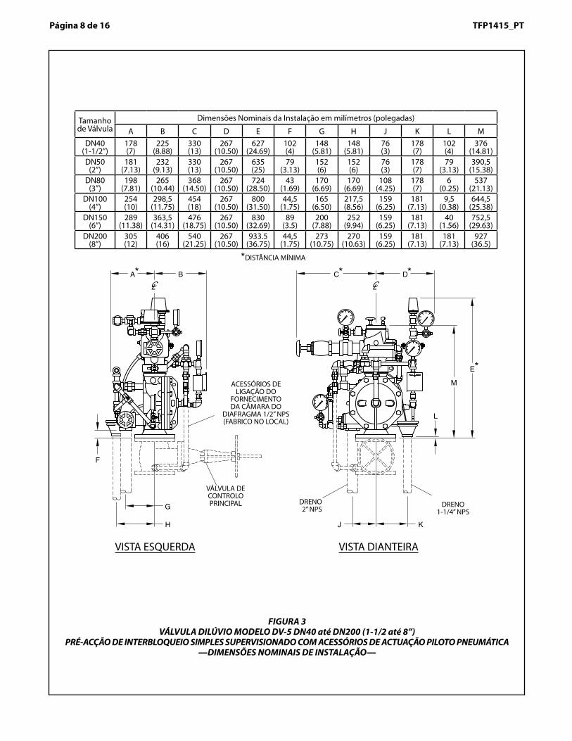
FIGURA 3VÁLVULA DILÚVIO MODELO DV-5 DN40 até DN200 (1-1/2 até 8”)
PRÉ-ACÇÃO DE INTERBLOQUEIO SIMPLES SUPERVISIONADO COM ACESSÓRIOS DE ACTUAÇÃO PILOTO PNEUMÁTICA—DIMENSÕES NOMINAIS DE INSTALAÇÃO—
Tamanho de Válvula
Dimensões Nominais da Instalação em milímetros (polegadas)
A B C D E F G H J K L MDN40
(1-1/2”)178(7)
225(8.88)
330(13)
267(10.50)
627(24.69)
102(4)
148(5.81)
148(5.81)
76(3)
178(7)
102(4)
376(14.81)
DN50(2”)
181(7.13)
232(9.13)
330(13)
267(10.50)
635(25)
79(3.13)
152(6)
152(6)
76(3)
178(7)
79(3.13)
390,5(15.38)
DN80(3”)
198 (7.81)
265(10.44)
368(14.50)
267(10.50)
724(28.50)
43(1.69)
170(6.69)
170(6.69)
108(4.25)
178(7)
6(0.25)
537(21.13)
DN100(4”)
254(10)
298,5(11.75)
454(18)
267(10.50)
800(31.50)
44,5(1.75)
165(6.50)
217,5(8.56)
159(6.25)
181(7.13)
9,5(0.38)
644,5(25.38)
DN150(6”)
289(11.38)
363,5(14.31)
476(18.75)
267(10.50)
830(32.69)
89(3.5)
200(7.88)
252(9.94)
159(6.25)
181(7.13)
40(1.56)
752,5(29.63)
DN200(8”)
305(12)
406(16)
540(21.25)
267(10.50)
933.5(36.75)
44,5(1.75)
273(10.75)
270(10.63)
159(6.25)
181(7.13)
181(7.13)
927(36.5)
DISTÂNCIA MÍNIMA
ACESSÓRIOS DE LIGAÇÃO DO
FORNECIMENTO DA CÂMARA DO
DIAFRAGMA 1/2” NPS (FABRICO NO LOCAL)
VÁLVULA DE CONTROLO PRINCIPAL DRENO
2” NPSDRENO
1-1/4” NPS
VISTA ESQUERDA VISTA DIANTEIRA
the Diaphragm Chamber to hold theDiaphragm closed against the watersupply pressure. When the DV-5 Valveis set for service, the DiaphragmChamber is pressurized through thetrim connections from the inlet side ofthe system’s main control valve, suchas an O.S.&Y. gate valve or butterflyvalve (Fig. 1).
Opening of a pilot sprinkler, releasespneumatic pressure from the pilot line.In turn, the Dry Pilot Actuator (Item D3- Fig. 2A) opens and releases waterfrom the Diaphragm Chamber fasterthan it can be replenished through the1/8 inch (3,2 mm) restriction providedby the Model ASV-1 Automatic Shut-Off Valve in the diaphragm supply con-nection (Item 5 - Fig. 2A, also de-scribed in Technical Data SheetTFP1384). This results in a rapid pres-sure drop in the Diaphragm Chamberto below the valve trip point. The watersupply pressure then forces the Dia-phragm open, permitting water to flowinto the system piping, as well asthrough the Alarm Port to actuate thesystem alarms
As water flows into the system, thepilot chamber of the Model ASV-1Automatic Shut-Off Valve (Item 5 - Fig.2A) becomes pressurized and theASV-1 automatically shuts off the dia-phragm chamber supply flow to theDV-5 Diaphragm Chamber. Shuttingoff the diaphragm chamber supply flowprevents the DV-5 Diaphragm Cham-ber from becoming re-pressurized,thereby preventing inadvertent closingof the DV-5 during a fire (as may be thecase if an actuation device other thana pilot sprinkler were to be closed afterits initial operation, for example a re-mote manual control station).
WARNINGThe Model DV-5 Supervised Single In-terlock Preaction System with Dry PilotActuation Trim described herein mustbe installed and maintained in compli-ance with this document, as well aswith the applicable standards of theNational Fire Protection Association,in addition to the standards of anyother authorities having jurisdiction.Failure to do so may impair the per-formance of the related devices.
The owner is responsible for maintain-ing their fire protection system and de-vices in proper operating condition.The installing contractor or manufac-turer should be contacted with anyquestions.
TechnicalDataApprovalsUL and C-UL Listed.
Deluge ValveModel DV-5.
Riser Check ValveModel CV-1FR.
NOTE1-1/2 inch (DN40) risers utilize a 2 inch(DN50) Riser Check Valve in combina-tion with the 1-1/2 inch (DN40) ModelDV-5 Deluge Valve.
Valve TrimThe Supervised Single Interlock Pre-action System With Dry Pilot ActuationTrim (Fig. 2A/2B) forms a part of thelaboratory listings and approvals. Thetrim is necessary for proper operationof the DV-5 Valve.
Each package of trim includes the fol-lowing items:
• Water Supply Pressure Gauge• Diaphragm Chamber
Pressure Gauge• Diaphragm Chamber Connections• Manual Control Station• Main Drain Valve• System Drain Valve• Alarm Test Valve• Automatic Drain Valve• System Air Pressure Gauge• Air Supply Connections• Low Air Pressure Supervisory
Switch• Waterflow Pressure Alarm Switch• Dry Pilot Actuator• Dry Pilot Line Pressure Gauge• Dry Pilot Line Low Pressure Alarm
Switch
To ease field assembly of the trim ar-rangement, the trim components areprovided par tially assembled asshown in Figure 2B.
The trim arrangement is provided withgalvanized or black nipples and fit-tings. The galvanized trim is intendedfor non-corrosive or corrosive condi-tions, whereas the black trim is princi-pally intended for use with AFFF sys-tems.
NOTEWhen the system pressure is greaterthan 175 psi (12,1 bar), provision is tobe made to replace the standard order300 psi (20,7 bar) Water PressureGauges, shown in Figure 2A/2B with
separately ordered 600 psi (41,4 bar)Water Pressure Gauges.
Detection SystemIn order for a single interlock preactionsystem to be hydraulically calculatedas a wet pipe system, as opposed to adry pipe sprinkler system, the detec-tion system must be designed to oper-ate sooner than the automatic sprin-klers on the sprinkler piping. In thecase of dry pilot actuation, the systemdesigner selects pilot sprinklers thatwill operate sooner than the automaticsprinklers chosen for use on the sprin-kler piping.
The Supervised Single Interlock Pre-action System With Dry Pilot ActuationTrim provides for connection of a de-tection system consisting of dry pilotline sprinklers (heat detectors) andmanual control stations intercon-nected with minimum 1/2 inch (DN15)Schedule 40 steel pipe. The pilot line,which is pressurized with air or nitro-gen, is connected to the “Dry Pilot De-tection” connection shown in Figure2B. Nominal installation dimensionsfor the Supervised Single InterlockPreaction System With Dry Pilot Ac-tuation Trim are shown in Figure 3.
Dry pilot line sprinklers are to be mini-mum 5.6 K-factor orifice listed or ap-proved automatic sprinklers. ManualControl Stations are to be the ModelMC-1 described in Technical DataSheet TFP1382.
The Dry Pilot Actuation Trim is pro-vided with a listed and approved ModelDP-1 Dry Pilot Actuator, which is de-scribed in Technical Data SheetTFP1380. The Actuator is rated for useat a maximum pilot service pressure of50 psi (3,4 bar) and a maximum watersupply service pressure of 250 psi(17,2 bar).
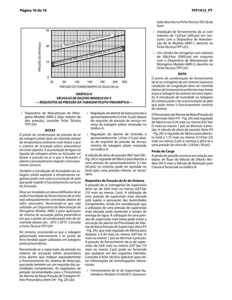
Graph A shows the “minimum pilot lineservice pressure” as a function of thewater supply pressure. The pressure inthe dry pilot actuation system must beautomatically maintained using one ofthe following maintenance devices, asappropriate.
• Model AMD-1 Air Maintenance De-vice (pressure reducing type), referto Technical Data Sheet TFP1221.
• Model AMD-2 Air Maintenance De-vice (compressor control type), referto Technical Data Sheet TFP1231.
• Model AMD-3 Nitrogen Mainte-nance Device (high pressure reduc-ing type), refer to Technical DataSheet TFP1241.
NOTESThe dew point of the pilot line air pres-sure must be maintained below the
Page 9 of 16TFP1415TFP1415_PT Página 9 de 16
tipo diafragma que depende da pressão da água na Câmara do Diafragma para manter o Diafragma fechado em relação à pressão do fornecimento de água. Quando a Válvu-la DV-5 é regulada para serviço, a Câmara do Diafragma é pressurizada através das ligações de acessórios no lado de aspiração da válvula de controlo principal do sistema, como uma válvula de cunha com fuso as-cendente ou válvula de borboleta (Fig. 1).
A abertura de um sprinkler piloto liberta pressão pneumática da tubagem piloto. Por sua vez, o Actuador Piloto Pneumático (Item D3 - Fig. 2A) é aberto e liberta água da Câmara do Diafragma mais depressa do que o seu reabastecimento através da restrição de 3,2 mm (1/8”) fornecida pela Válvula de Seccionamento Automático Modelo ASV-1 na ligação de fornecimento do diafragma (Item 5 - Fig. 2A, também descrita na Ficha Técnica TFP1384). Isto resulta numa queda de pressão rápida na Câmara do Diafragma abaixo do ponto de activação da válvula. A pressão do fornecimento de água força a abertura do Diafragma, permitindo que a água entre na tubagem do sistema, bem como pela passagem para alarme para ac-tuar os alarmes do sistema.
À medida que a água entra no sistema, a câmara piloto da Válvula de Seccionamen-to Automático Modelo ASV-1 (Item 5 - Fig. 2A) fica pressurizada e a ASV-1 encerra au-tomaticamente o caudal de fornecimento da câmara do diafragma para a Câmara do Diafragma DV-5. Encerrar o caudal de for-necimento da câmara do diafragma evita que a Câmara do Diafragma DV-5 volte a ficar pressurizada, evitando assim o encer-ramento inadvertido da DV-5 durante um incêndio (que pode acontecer se um dis-positivo de actuação que não o sprinkler piloto for fechado após o funcionamento inicial, por exemplo, um posto de controlo manual remoto).
AVISOO Sistema de Pré-acção de Interbloqueio Simples Supervisionado Modelo DV-5 com Acessórios de Actuação Piloto Pneumática aqui descrito, tem de ser instalado e manti-do em conformidade com este documento, bem como com as normas aplicáveis da NFPA, para além das normas de quaisquer outras autoridades competentes. O incum-primento das normas pode pôr em causa o funcionamento dos dispositivos relacio-nados.
O proprietário é responsável pela manu-tenção do seu sistema e dispositivos de protecção contra incêndios em condições adequadas de funcionamento. A empresa de instalação ou o fabricante devem ser con-tactados em caso de dúvidas.
Dados Técnicos HomologaçõesListado por UL e C-UL.
Válvula de DilúvioModelo DV-5.
Válvula de Retenção para ColunaModelo CV-1FR.
NOTAOs tubos de extensão DN40 (1-1/2”) utilizam uma Válvula de Retenção para Coluna DN50 (2”) em conjunto com a Válvula de Dilúvio DN40 (1-1/2”) Modelo DV-5.
Acessórios auxiliares da válvula O Sistema de Pré-acção de Interbloqueio Simples Supervisionado com Acessórios de Actuação Piloto Pneumática (Fig. 2A/2B) forma uma parte das listagens e homolo-gações laboratoriais. Os acessórios são ne-cessários para o funcionamento correcto da válvula DV-5.
Cada conjunto de acessórios inclui os se-guintes itens:
• Manómetro do Fornecimento de Água• Manómetro da Câmara do Diafragma• Ligações da Câmara do Diafragma• Posto de Controlo Manual• Válvula de Drenagem Principal• Válvula de Drenagem do Sistema• Válvula de Teste de Alarme• Válvula de Drenagem Automática• Manómetro de Ar do Sistema• Ligações de Fornecimento de Ar• Pressóstato de Baixa Pressão de Ar de
Supervisão• Pressóstato de Alarme de Débito• Actuador Piloto Pneumático• Manómetro de Tubagem Piloto Pneu-
mática• Pressóstato de Alarme de Baixa Pressão
de Tubagem Piloto PneumáticaPara a montagem fácil da combinação dos acessórios no local, os acessórios são forne-cidos parcialmente montados, como mos-trado na Figura 2B.
A combinação dos acessórios é fornecida com uniões roscadas e juntas galvanizadas ou pretas. Os acessórios galvanizados desti-nam-se a condições corrosivas ou não cor-rosivas, e os acessórios pretos destinam-se principalmente à utilização com sistemas AFFF.
NOTAQuando a pressão do sistema for superior a 12,1 bar (175 psi), devem ser tomadas pro-vidências para substituir os Manómetros de Água de encomenda padrão de 20,7 bar
(300 psi), mostrados na Figura 2A/2B, por Manómetros de Água de 41,4 bar (600 psi), encomendados em separado.
Sistema de DetecçãoPara que um sistema de pré-acção de in-terbloqueio simples seja calculado hidrau-licamente como um sistema de tubagem húmida (hidráulica), por oposição a um sis-tema de sprinklers de tubagem seca (pneu-mática), o sistema de detecção tem de ser projectado para funcionar mais cedo do que os sprinklers automáticos na tubagem de sprinklers. No caso de actuação piloto pneumática, o projectista do sistema selec-ciona sprinklers piloto que vão funcionar mais cedo do que os sprinklers automáti-cos escolhidos para utilização na tubagem de sprinklers.
O Sistema de Pré-acção de Interbloqueio Simples Supervisionado com Acessórios de Actuação Piloto Pneumática fornece uma li-gação ao sistema de detecção, que consiste em sprinklers de tubagem piloto pneumáti-ca (detectores de calor) e postos de controlo manual interligados com, no mínimo, tuba-gem em aço DN15 (1/2”) especificação 40. A tubagem piloto, que é pressurizada com ar ou nitrogénio, é ligada à ligação “Detec-ção Piloto Pneumática”, mostrada na Figura 2B. As dimensões nominais de instalação do Sistema de Pré-acção de Interbloqueio Simples Supervisionado com Acessórios de Actuação Piloto Pneumática são mostradas na Figura 3.
Os sprinklers de tubagem piloto pneumáti-ca têm de ser, no mínimo, listados com ori-fício K 80 ou sprinklers automáticos apro-vados. Os Postos de Controlo Manual têm de ser do Modelo MC-1, descrito na Ficha Técnica TFP1382.
Os Acessórios de Actuação Piloto Pneumá-tica são fornecidos com um Actuador Piloto Pneumático Modelo DP-1 listado e aprova-do, descrito na Ficha Técnica TFP1380. O Ac-tuador está indicado para utilização a uma pressão de serviço máxima do piloto de 3,4 bar (50 psi) e uma pressão de serviço de fornecimento de água máxima de 17,2 bar (250 psi). .
O gráfico A mostra a “pressão de serviço mínima da tubagem piloto” como uma fun-ção da pressão de fornecimento de água. A pressão do sistema de actuação piloto pneumática deve ser mantida automati-camente, utilizando um dos seguintes dis-positivos de manutenção, consoante apro-priado.
• Dispositivo de Manutenção de Ar Mo-delo AMD-1 (tipo redutor de pressão), consulte Ficha Técnica TFP1221.
• Dispositivo de Manutenção de Ar Mo-delo AMD-2 (tipo controlo de compres-sor), consulte Ficha Técnica TFP1231.
lowest ambient temperature to whichthe dry pilot actuation system will beexposed. Accumulation of water in thepilot line connection to the Actuator willlower the air pressure at which theActuator will open and possibly pre-vent proper operation.
Also, introduction of moisture into thepilot lines exposed to freezing tem-peratures can create an ice buildupthat could prevent proper operation ofthe Actuator.
An air dryer must be installed wherethe moisture content of the air supplyis not properly controlled at less thanthe required value. It is recommendedthat an AMD-3 Nitrogen MaintenanceDevice be utilized in dry pilot actuationsystem applications where the dewpoint must be maintained below -20F/-29C. See Technical Data SheetTFP1241.
At a minimum, it is recommended thatinternally galvanized pipe and castiron fittings be used for dry pilot lines.
Supervision of the pressure in the drypilot actuation system and/or alarmthat separately indicates operation ofthe detection system is recommendedand may be required by the authorityhaving jurisdiction. The recommendedpressure settings for the Dry Pilot LineLow Pressure Alarm Switch (Item D4 -Fig. 2A) are as follows:
• Low pressure alarm setting at ap-proximately 6 psi (0,4 bar) below theminimum pilot line service pressurerequirement shown in Graph A.
• Fire alarm setting at approximately15 psi (1,0 bar) below the minimumpilot line service pressure require-ment shown in Graph A.
The Pressure Relief Valve (Ref. Item
D6 - Fig. 2A) is factory set to relieve ata pressure of approximately 45 psi (3,1bar); however, it may be field adjustedto a lower pressure, if required.
System Air Pressure RequirementsThe supervisory air (nitrogen) pres-sure is to be 10 plus or minus 2 psi(0,69 plus or minus 0,07 bar). The useof a higher supervisory pressure issubject to approval by the AuthorityHaving Jurisdiction, and it should beunderstood that the use of a highersupervisory pressure may increasewater delivery time. The use of a lowersupervisory pressure may preventclearing the alarm of the SupervisoryLow Pressure Alarm Switch (Item P3 -Fig. 2A), which is factory set to alarmat 5 plus or minus 1 psi (0,34 plus orminus 0,07 bar) on decreasing pres-sure. The supervisory air supply pres-sure of 10 plus or minus 2 psi (0,69plus or minus 0,07 bar) can be pro-vided by any of the following methods.Refer to the applicable data sheet forlaboratory approval information.
• Model G16AC812 (self contained)Automatic Supervisory Air Supplydescribed in Gem Technical DataSheet TD126.
• A maximum 200 psi (13,8 bar) plantair supply in combination with theModel AMD-1 Air Maintenance De-vice described in Technical DataSheet TFP1221.
• A maximum 3000 psi (206,9 bar)nitrogen cylinder in combination withthe Model AMD-3 Nitrogen Mainte-nance Device described in Techni-cal Data Sheet TFP1241.
NOTEThe dew point of the air or nitrogensupply for a system exposed to freez-
ing conditions must be maintained be-low the lowest ambient temperature towhich the system piping will be ex-posed. Introduction of moisture intothe system piping can create ice buildup which could prevent proper opera-tion of the system.
The Supervisory Low Pressure AlarmSwitch (Item P3 - Fig. 2A) is factory setat 5 plus or minus 1 psi (0,34 plus orminus 0,07 bar) on decreasing pres-sure. The Pressure Relief Valve (ItemP4 - Fig. 2A) is factory set to fully openat 25 plus or minus 2 psi (1,72 plus orminus 0,14 bar) and it begins to crackopen at a pressure of about 18 psi(1,24 bar).
Friction LossThe nominal pressure loss versus flowdata for the Model DV-5 Deluge Valveplus Riser Check Valve is provided inGraph B.
Page 10 of 16 TFP1415
GRAPH AMODEL DV-5 DELUGE VALVES
— DRY PILOT LINE PRESSURE REQUIREMENTS —
WATER SUPPLY PRESSURE IN PSI
100
RANGE OF ACTUATOR OPENING PRESSUREMINIMUM SYSTEM AIR PRESSURE
AIR
PR
ES
SU
RE
INP
SI
20 60
15
0
30
45
140 180 250200
Página 10 de 16 TFP1415_PT
• Dispositivo de Manutenção de Nitro-génio Modelo AMD-3 (tipo redutor de alta pressão), consulte Ficha Técnica TFP1241
NOTASO ponto de condensação da pressão do ar da tubagem piloto deve ser mantido abaixo da temperatura ambiente mais baixa a que o sistema de actuação piloto pneumática vai estar exposto. A acumulação de água na ligação da tubagem piloto ao Actuador vai baixar a pressão do ar a que o Actuador é aberto e provavelmente impedir o funciona-mento correcto.
Também a introdução de humidade nas tu-bagens piloto expostas a temperaturas ne-gativas pode criar uma acumulação de gelo que pode impedir o funcionamento correcto do Actuador.
Deve ser instalado um desumidificador de ar onde a humidade do fornecimento de ar não seja adequadamente controlada abaixo do valor necessário. Recomenda-se que seja utilizado um Dispositivo de Manutenção de Nitrogénio Modelo AMD-3 para aplicações de sistema de actuação piloto pneumática em que o ponto de condensação tem de ser mantido abaixo dos - 29°C (-20°F). Consulte a Ficha Técnica TFP1241.
No mínimo, recomenda-se que a tubagem galvanizada internamente e as juntas de ferro fundido sejam utilizadas em tubagens piloto pneumáticas.
Recomenda-se a supervisão da pressão no sistema de actuação piloto pneumática e/ou alarme que indique separadamente o funcionamento do sistema de detecção, que pode também ser um requisito das au-toridades competentes. As regulações de pressão recomendadas para o Pressóstato de Alarme de Baixa Pressão de Tubagem Pi-loto Pneumática (Item D4 - Fig. 2A) são:
• Regulação do alarme de baixa pressão a aproximadamente 0,4 bar (6 psi) abaixo do requisito de pressão de serviço mí-nima da tubagem piloto mostrada no Gráfico A.
• Regulação do alarme de incêndio a aproximadamente 1,0 bar (15 psi) abai-xo do requisito de pressão de serviço mínima da tubagem piloto mostrada no Gráfico A.
A válvula de alívio de pressão (Ref. Item D6 - Fig. 2A) é regulada de fábrica para libertar a uma pressão de aproximadamente 3,1 bar (45 psi); no entanto, pode ser ajustada no local para uma pressão inferior, se neces-sário.
Requisitos de Pressão de Ar do Sistema A pressão de ar (nitrogénio) de supervisão deve ser de 0,69 mais ou menos 0,07 bar (10 mais ou menos 2 psi). A utilização de uma pressão de supervisão mais elevada está sujeita a aprovação das Autoridades Competentes, tendo em consideração que a utilização de uma pressão de supervisão mais elevada pode aumentar o tempo de entrega de água. A utilização de uma pres-são de supervisão mais baixa pode evitar a actuação do alarme do Pressóstato de Alar-me de Baixa Pressão de Supervisão (Item P3 - Fig. 2A), que está regulado de fábrica para disparar a 0,34 mais ou menos 0,07 bar (5 mais ou menos 1 psi) ao diminuir a pressão. A pressão do fornecimento de ar de super-visão de 0,69 mais ou menos 0,07 bar (10 mais ou menos 2 psi) pode ser fornecida por qualquer um dos seguintes métodos. Consulte a ficha técnica aplicável para ob-ter informações de homologações labora-toriais.
• Fornecimento de Ar de Supervisão Au-tomático Modelo G16AC812 (autocon-
tido) descrito na Ficha Técnica TD126 da Gem.
• Instalação de fornecimento de ar com máximo de 13,8 bar (200 psi) em con-junto com o Dispositivo de Manuten-ção de Ar Modelo AMD-1, descrito na Ficha Técnica TFP1221.
• Um cilindro de nitrogénio com máximo de 206,9 bar (3000 psi) em conjunto com o Dispositivo de Manutenção de Nitrogénio Modelo AMD-3, descrito na Ficha Técnica TFP1241.
NOTAO ponto de condensação do fornecimento de ar ou nitrogénio de um sistema exposto a condições de congelação deve ser mantido abaixo da temperatura ambiente mais baixa a que a tubagem do sistema vai estar expos-ta. A introdução de humidade na tubagem do sistema pode criar a acumulação de gelo que pode evitar o funcionamento correcto do sistema.
O Pressóstato de Alarme de Baixa Pressão de Supervisão (Item P3 - Fig. 2A) está regulado de fábrica nos 0,34 mais ou menos 0,07 bar (5 mais ou menos 1 psi) ao diminuir a pres-são. A válvula de alívio de pressão (Item P4 - Fig. 2A) é regulada de fábrica para abertu-ra total a 1,72 mais ou menos 0,14 bar (25 mais ou menos 2 psi) e começa a abrir-se a uma pressão de cerca de 1,24 bar (18 psi).
Perda de Carga A perda de pressão nominal em relação aos dados de fluxo da Válvula de Dilúvio Mo-delo DV-5 mais a Válvula de Retenção para Coluna é fornecida no Gráfico B.
PRES
SÃO
DO
AR
EM p
si
PRESSÃO DO FORNECIMENTO DE ÁGUA EM psi
GRÁFICO AVÁLVULAS DE DILÚVIO MODELO DV-5
— REQUISITOS DE PRESSÃO DA TUBAGEM PILOTO PNEUMÁTICA—
INTERVALO DA PRESSÃO DE ABERTURA DO ACTUADORPRESSÃO MÍNIMA DO AR DO SISTEMA
Page 11 of 16TFP1415
200 400 1000 3000200060010050
FLOW RATE IN GALLONS PER MINUTE (GPM)
3.0
NO
MIN
AL
PR
ES
SU
RE
DR
OP
IN P
OU
ND
S P
ER
SQ
UA
RE
INC
H(P
SI)
0.8
0.4
0.5
0.6
0.7
1.00.9
2.0
6.0
4.0
5.0
9.0
7.0
8.0
10.0
15.0
FLOW RATE IN LITRES PER MINUTE (LPM)
200 1000600400
(1 GPM = 3,785 LPM)
2000 70003000 5000 10000
(1P
SI=
0,06
895
BA
R)
NO
MIN
AL
PR
ES
SU
RE
DR
OP
IN B
AR
0,040
0,030
0,050
0,080
0,060
0,070
0,0900,100
0,200
0,800
0,400
0,300
0,600
0,500
0,700
1,0000,900
2 IN
CH
(DN
50)
1-1/
2IN
CH
(DN
40)
6 IN
CH
(DN
150)
4 IN
CH
(DN
100)
3 IN
CH
(DN
80)
8 IN
CH
(DN
200)
GRAPH BDELUGE AND CHECK VALVE COMBINATION*
— NOMINAL PRESSURE LOSS VERSUS FLOW —
* Model DV-5 Deluge Valve combined with Model CV-1FR Riser Check Valve
**1-1/2 inch Model DV-5 Deluge Valve combined with 2 inch Model CV-1FR Riser Check Valve
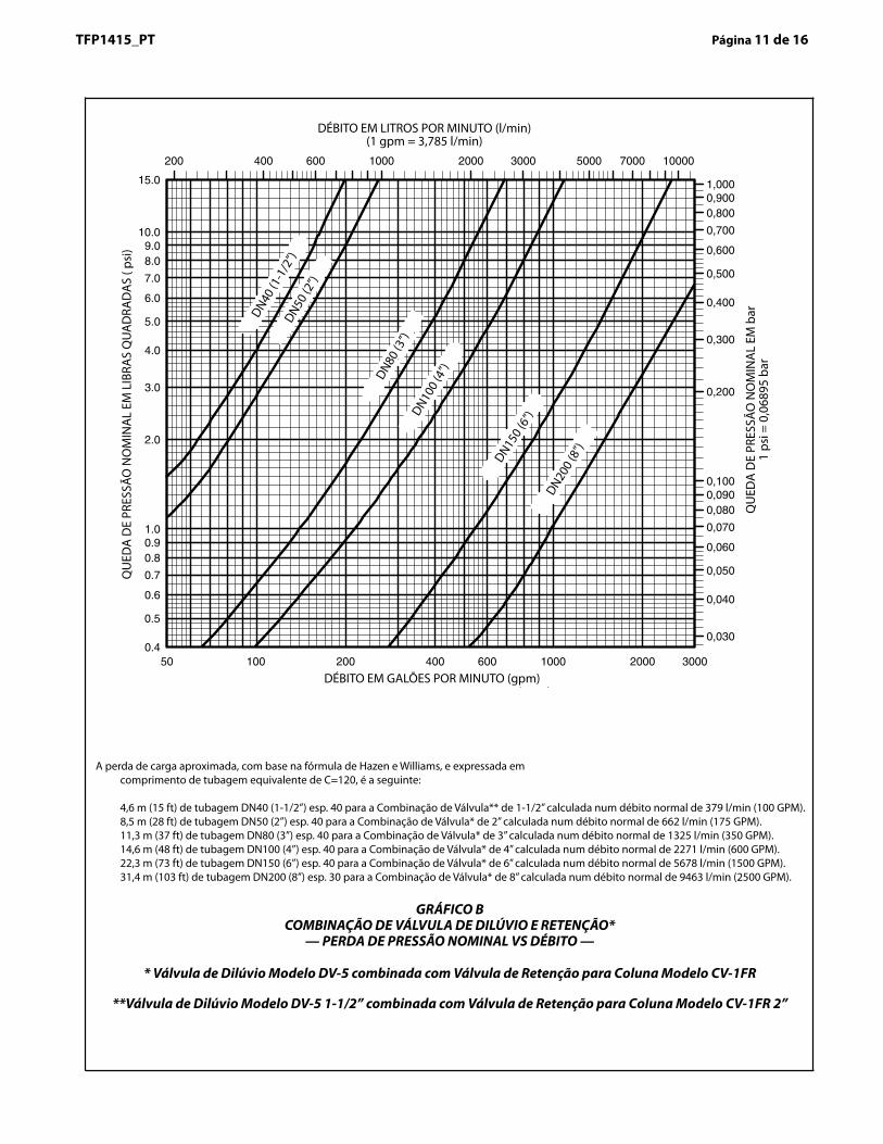
The approximate friction loss, based on the Hazen and Williams formula and expressed in equivalent length of pipe with C=120, is asfollows:
15 feet of 1-1/2 Sch. 40 pipe for the 1-1/2 inch Valve Combination** calculated on a typical flow rate of 100 GPM.28 feet of 2 inch Sch. 40 pipe for the 2 inch Valve Combination* calculated on a typical flow rate of 175 GPM.37 feet of 3 inch Sch. 40 pipe for the 3 inch Valve Combination* calculated on a typical flow rate of 350 GPM.48 feet of 4 inch Sch. 40 pipe for the 4 inch Valve Combination* calculated on a typical flow rate of 600 GPM.73 feet of 6 inch Sch. 40 pipe for the 6 inch Valve Combination* calculated on a typical flow rate of 1500 GPM.103 feet of 8 inch Sch. 30 pipe for the 8 inch Valve Combination* calculated on a typical flow rate of 2500 GPM.
TFP1415_PT Página 11 de 16
DÉBITO EM GALÕES POR MINUTO (gpm)
GRÁFICO BCOMBINAÇÃO DE VÁLVULA DE DILÚVIO E RETENÇÃO*
— PERDA DE PRESSÃO NOMINAL VS DÉBITO —
QU
EDA
DE
PRES
SÃO
NO
MIN
AL
EM L
IBRA
S Q
UA
DRA
DA
S ( p
si)
DÉBITO EM LITROS POR MINUTO (l/min) (1 gpm = 3,785 l/min)
DN40 (1
-1/2
”)DN50
(2”)
DN80 (3
”)DN10
0 (4
”)
DN150 (
6”)
DN200
(8”)
QU
EDA
DE
PRES
SÃO
NO
MIN
AL
EM b
ar1
psi =
0,0
6895
bar
A perda de carga aproximada, com base na fórmula de Hazen e Williams, e expressada em comprimento de tubagem equivalente de C=120, é a seguinte:
4,6 m (15 ft) de tubagem DN40 (1-1/2”) esp. 40 para a Combinação de Válvula** de 1-1/2” calculada num débito normal de 379 l/min (100 GPM). 8,5 m (28 ft) de tubagem DN50 (2”) esp. 40 para a Combinação de Válvula* de 2” calculada num débito normal de 662 l/min (175 GPM). 11,3 m (37 ft) de tubagem DN80 (3”) esp. 40 para a Combinação de Válvula* de 3” calculada num débito normal de 1325 l/min (350 GPM). 14,6 m (48 ft) de tubagem DN100 (4”) esp. 40 para a Combinação de Válvula* de 4” calculada num débito normal de 2271 l/min (600 GPM). 22,3 m (73 ft) de tubagem DN150 (6”) esp. 40 para a Combinação de Válvula* de 6” calculada num débito normal de 5678 l/min (1500 GPM). 31,4 m (103 ft) de tubagem DN200 (8”) esp. 30 para a Combinação de Válvula* de 8” calculada num débito normal de 9463 l/min (2500 GPM).
* Válvula de Dilúvio Modelo DV-5 combinada com Válvula de Retenção para Coluna Modelo CV-1FR
**Válvula de Dilúvio Modelo DV-5 1-1/2” combinada com Válvula de Retenção para Coluna Modelo CV-1FR 2”
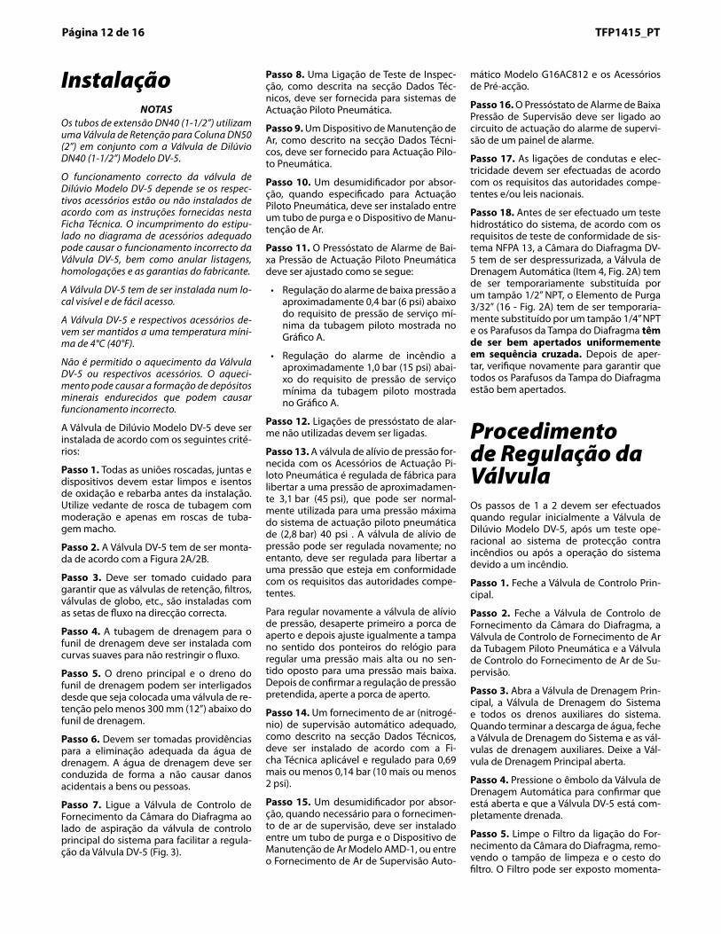
InstallationNOTES
1-1/2 inch (DN40) risers utilize a 2 inch(DN50) Riser Check Valve in combina-tion with the 1-1/2 inch (DN40) ModelDV-5 Deluge Valve.
Proper operation of the Model DV-5Deluge Valves depends upon their trimbeing installed in accordance with theinstructions given in this TechnicalData Sheet. Failure to follow the ap-propriate trim diagram may preventthe DV-5 Valve from functioning prop-erly, as well as void listings, approvals,and the manufacturer’s warranties.
The DV-5 Valve must be installed in areadily visible and accessible location.
The DV-5 Valve and associated trimmust be maintained at a minimum tem-perature of 40°F/4°C.
Heat tracing of the DV-5 Valve or itsassociated trim is not permitted. Heattracing can result in the formation ofhardened mineral deposits that are ca-pable of preventing proper operation.
The Model DV-5 Deluge Valve is to beinstalled in accordance with the follow-ing criteria:
Step 1. All nipples, fittings, and de-vices must be clean and free of scaleand burrs before installation. Use pipethread sealant sparingly on male pipethreads only.
Step 2. The DV-5 Valve must betrimmed in accordance with Figure2A/2B.
Step 3. Care must be taken to ensurethat check valves, strainers, globevalves, etc. are installed with the flowarrows in the proper direction.
Step 4. Drain tubing to the drip funnelmust be installed with smooth bendsthat will not restrict flow.
Step 5. The main drain and drip funneldrain may be interconnected provideda check valve is located at least 12inches (300 mm) below the drip funnel.
Step 6. Suitable provision must bemade for disposal of drain water.Drainage water must be directed suchthat it will not cause accidental dam-age to property or danger to persons.
Step 7. Connect the DiaphragmChamber Supply Control Valve to theinlet side of the system’s main controlvalve in order to facilitate setting of theDV-5 Valve (Fig. 3).
Step 8. An Inspector’s Test Connec-tion, as described in the TechnicalData section, must be provided for DryPilot Actuation systems.
Step 9. An Air Maintenance Device, asdescribed in the Technical Data Sec-tion, must be provided for Dry PilotActuation.
Step 10. A desiccant dryer, whenspecified for Dry Pilot Actuation, is tobe installed between a drip leg and theAir Maintenance Device.
Step 11. The Low Pressure AlarmSwitch for Dry Pilot Actuation is to beadjusted as follows:
• Low pressure alarm setting at ap-proximately 6 psi (0,4 bar) below theminimum pilot line service pressurerequirement shown in Graph A.
• Fire alarm setting at approximately15 psi (1,0 bar) below the minimumpilot line service pressure require-ment shown in Graph A.
Step 12. Unused pressure alarmswitch connections must be plugged.
Step 13. The Pressure Relief Valveprovided with the Dry Pilot ActuationTrim is factory set to relieve at a pres-sure of approximately 45 psi (3,1 bar),which can typically be used for a maxi-mum dry pilot actuation system pres-sure of 40 psi (2,8 bar). The PressureRelief Valve may be reset; however, itmust be reset to relieve at a pressurethat is in accordance with the require-ments of the authority having jurisdic-tion.
To reset the Pressure Relief Valve, firstloosen the jam nut and then adjust thecap accordingly — clockwise for ahigher pressure setting or counter-clockwise for a lower pressure setting.After verifying the desired pressuresetting, tighten the jam nut.
Step 14. A suitable automatic supervi-sory air (nitrogen) supply, as describedin the Technical Data Section, is to beinstalled in accordance with the appli-cable Technical Data Sheet and set for10 plus or minus 2 psi (0,69 plus orminus 0,14 bar).
Step 15. A desiccant dryer, when re-quired for the supervisory air supply, isto be installed between a drip leg andthe Model AMD-1 Air Maintenance De-vice or between the Model G16AC812Automatic Supervisory Air Supply andthe Preaction Trim.
Step 16. The Supervisory Low Pres-sure Alarm Switch is to be wired to thesupervisory alarm initiating circuit ofan alarm panel.
Step 17. Conduit and electrical con-nections are to be made in accordancewith the requirements of the authorityhaving jurisdiction and/or the NationalElectric Code.
Step 18. Before a system hydrostatic
test is performed in accordance withNFPA 13 system acceptance test re-quirements, the DV-5 DiaphragmChamber is to be depressurized; theAutomatic Drain Valve (Item 4, Fig. 2A)is to be temporarily replaced with a 1/2inch NPT plug, the 3/32 inch Vent Fit-ting (16 - Fig. 2A) is to be temporarilyreplaced with a 1/4 inch NPT plug, andthe Diaphragm Cover Bolts must beuniformly and securely tightenedusing a cross-draw sequence. Aftertightening, double-check to make cer-tain that all of the Diaphragm CoverBolts are securely tightened.
Valve SettingProcedureSteps 1 through 12 are to be per-formed when initially setting the ModelDV-5 Deluge Valve; after an opera-tional test of the fire protection system;or, after system operation due to a fire.
Step 1. Close the Main Control Valve.
Step 2. Close the Diaphragm Cham-ber Supply Control Valve, the Dry PilotLine Air Supply Control Valve, and theSupervisory Air Supply Control Valve.
Step 3. Open the Main Drain Valve,System Drain Valve, and all auxiliarydrains in the system. After waterceases to discharge, close the SystemDrain Valve and auxiliary drain valves.Leave the Main Drain Valve open.
Step 4. Depress the plunger of theAutomatic Drain Valve to verify that itis open and that the DV-5 Valve iscompletely drained.
Step 5. Clean the Strainer in the Dia-phragm Chamber Supply connectionby removing the clean-out plug andstrainer basket. The Strainer may beflushed out by momentarily openingthe Diaphragm Chamber Supply Con-trol Valve.
Step 6. Reset the actuation system.
Manual Actuation — Push the operat-ing lever up; however, do not close thehinged cover at this time.
Dry Pilot Actuation — Replace oper-ated pilot sprinklers and/or reset themanual control stations. Re-establishdry pilot pneumatic pressure.
NOTEIn order to prevent the possibility of asubsequent operation of an over-heated solder type pilot sprinkler, anysolder type pilot sprinklers that werepossibly exposed to a temperaturegreater than their maximum rated am-bient must be replaced.
Step 7. Open the Diaphragm Chamber
Page 12 of 16 TFP1415Página 12 de 16 TFP1415_PT
InstalaçãoNOTAS
Os tubos de extensão DN40 (1-1/2”) utilizam uma Válvula de Retenção para Coluna DN50 (2”) em conjunto com a Válvula de Dilúvio DN40 (1-1/2”) Modelo DV-5.
O funcionamento correcto da válvula de Dilúvio Modelo DV-5 depende se os respec-tivos acessórios estão ou não instalados de acordo com as instruções fornecidas nesta Ficha Técnica. O incumprimento do estipu-lado no diagrama de acessórios adequado pode causar o funcionamento incorrecto da Válvula DV-5, bem como anular listagens, homologações e as garantias do fabricante.
A Válvula DV-5 tem de ser instalada num lo-cal visível e de fácil acesso.
A Válvula DV-5 e respectivos acessórios de-vem ser mantidos a uma temperatura míni-ma de 4°C (40°F).
Não é permitido o aquecimento da Válvula DV-5 ou respectivos acessórios. O aqueci-mento pode causar a formação de depósitos minerais endurecidos que podem causar funcionamento incorrecto.
A Válvula de Dilúvio Modelo DV-5 deve ser instalada de acordo com os seguintes crité-rios:
Passo 1. Todas as uniões roscadas, juntas e dispositivos devem estar limpos e isentos de oxidação e rebarba antes da instalação. Utilize vedante de rosca de tubagem com moderação e apenas em roscas de tuba-gem macho.
Passo 2. A Válvula DV-5 tem de ser monta-da de acordo com a Figura 2A/2B.
Passo �. Deve ser tomado cuidado para garantir que as válvulas de retenção, filtros, válvulas de globo, etc., são instaladas com as setas de fluxo na direcção correcta.
Passo 4. A tubagem de drenagem para o funil de drenagem deve ser instalada com curvas suaves para não restringir o fluxo.
Passo 5. O dreno principal e o dreno do funil de drenagem podem ser interligados desde que seja colocada uma válvula de re-tenção pelo menos 300 mm (12”) abaixo do funil de drenagem.
Passo 6. Devem ser tomadas providências para a eliminação adequada da água de drenagem. A água de drenagem deve ser conduzida de forma a não causar danos acidentais a bens ou pessoas.
Passo �. Ligue a Válvula de Controlo de Fornecimento da Câmara do Diafragma ao lado de aspiração da válvula de controlo principal do sistema para facilitar a regula-ção da Válvula DV-5 (Fig. 3).
Passo �. Uma Ligação de Teste de Inspec-ção, como descrita na secção Dados Téc-nicos, deve ser fornecida para sistemas de Actuação Piloto Pneumática.
Passo 9. Um Dispositivo de Manutenção de Ar, como descrito na secção Dados Técni-cos, deve ser fornecido para Actuação Pilo-to Pneumática.
Passo 10. Um desumidificador por absor-ção, quando especificado para Actuação Piloto Pneumática, deve ser instalado entre um tubo de purga e o Dispositivo de Manu-tenção de Ar.
Passo 11. O Pressóstato de Alarme de Bai-xa Pressão de Actuação Piloto Pneumática deve ser ajustado como se segue:
• Regulação do alarme de baixa pressão a aproximadamente 0,4 bar (6 psi) abaixo do requisito de pressão de serviço mí-nima da tubagem piloto mostrada no Gráfico A.
• Regulação do alarme de incêndio a aproximadamente 1,0 bar (15 psi) abai-xo do requisito de pressão de serviço mínima da tubagem piloto mostrada no Gráfico A.
Passo 12. Ligações de pressóstato de alar-me não utilizadas devem ser ligadas.
Passo 1�. A válvula de alívio de pressão for-necida com os Acessórios de Actuação Pi-loto Pneumática é regulada de fábrica para libertar a uma pressão de aproximadamen-te 3,1 bar (45 psi), que pode ser normal-mente utilizada para uma pressão máxima do sistema de actuação piloto pneumática de (2,8 bar) 40 psi . A válvula de alívio de pressão pode ser regulada novamente; no entanto, deve ser regulada para libertar a uma pressão que esteja em conformidade com os requisitos das autoridades compe-tentes.
Para regular novamente a válvula de alívio de pressão, desaperte primeiro a porca de aperto e depois ajuste igualmente a tampa no sentido dos ponteiros do relógio para regular uma pressão mais alta ou no sen-tido oposto para uma pressão mais baixa. Depois de confirmar a regulação de pressão pretendida, aperte a porca de aperto.
Passo 14. Um fornecimento de ar (nitrogé-nio) de supervisão automático adequado, como descrito na secção Dados Técnicos, deve ser instalado de acordo com a Fi-cha Técnica aplicável e regulado para 0,69 mais ou menos 0,14 bar (10 mais ou menos 2 psi).
Passo 15. Um desumidificador por absor-ção, quando necessário para o fornecimen-to de ar de supervisão, deve ser instalado entre um tubo de purga e o Dispositivo de Manutenção de Ar Modelo AMD-1, ou entre o Fornecimento de Ar de Supervisão Auto-
mático Modelo G16AC812 e os Acessórios de Pré-acção.
Passo 16. O Pressóstato de Alarme de Baixa Pressão de Supervisão deve ser ligado ao circuito de actuação do alarme de supervi-são de um painel de alarme.
Passo 1�. As ligações de condutas e elec-tricidade devem ser efectuadas de acordo com os requisitos das autoridades compe-tentes e/ou leis nacionais.
Passo 1�. Antes de ser efectuado um teste hidrostático do sistema, de acordo com os requisitos de teste de conformidade de sis-tema NFPA 13, a Câmara do Diafragma DV-5 tem de ser despressurizada, a Válvula de Drenagem Automática (Item 4, Fig. 2A) tem de ser temporariamente substituída por um tampão 1/2” NPT, o Elemento de Purga 3/32” (16 - Fig. 2A) tem de ser temporaria-mente substituído por um tampão 1/4” NPT e os Parafusos da Tampa do Diafragma têm de ser bem apertados uniformemente em sequência cruzada. Depois de aper-tar, verifique novamente para garantir que todos os Parafusos da Tampa do Diafragma estão bem apertados.
Procedimento de Regulação da VálvulaOs passos de 1 a 2 devem ser efectuados quando regular inicialmente a Válvula de Dilúvio Modelo DV-5, após um teste ope-racional ao sistema de protecção contra incêndios ou após a operação do sistema devido a um incêndio.
Passo 1. Feche a Válvula de Controlo Prin-cipal.
Passo 2. Feche a Válvula de Controlo de Fornecimento da Câmara do Diafragma, a Válvula de Controlo de Fornecimento de Ar da Tubagem Piloto Pneumática e a Válvula de Controlo do Fornecimento de Ar de Su-pervisão.
Passo �. Abra a Válvula de Drenagem Prin-cipal, a Válvula de Drenagem do Sistema e todos os drenos auxiliares do sistema. Quando terminar a descarga de água, feche a Válvula de Drenagem do Sistema e as vál-vulas de drenagem auxiliares. Deixe a Vál-vula de Drenagem Principal aberta.
Passo 4. Pressione o êmbolo da Válvula de Drenagem Automática para confirmar que está aberta e que a Válvula DV-5 está com-pletamente drenada.
Passo 5. Limpe o Filtro da ligação do For-necimento da Câmara do Diafragma, remo-vendo o tampão de limpeza e o cesto do filtro. O Filtro pode ser exposto momenta-
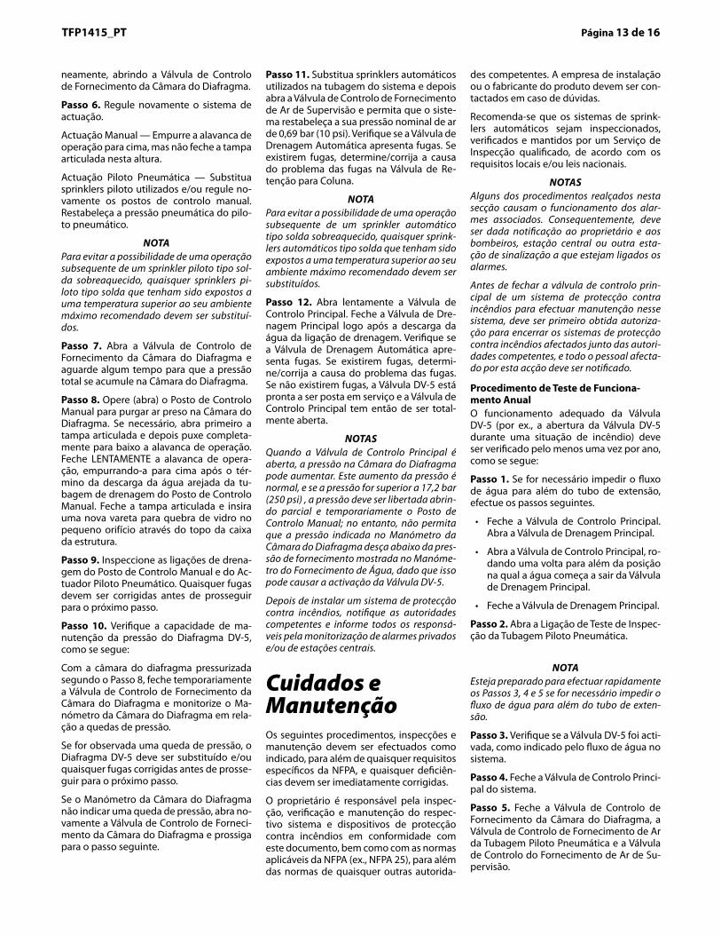
Supply Control Valve and allow time forfull pressure to build up in the Dia-phragm Chamber.
Step 8. Operate (open) the ManualControl Station to vent trapped air fromthe Diaphragm Chamber. If necessary,first open the hinged cover, and thenfully pull down on the operating lever.SLOWLY close the operating lever, bypushing it up, after aerated waterceases to discharge from the ManualControl Station drain tubing. Close thehinged cover and insert a new breakrod in the small hole through the top ofthe enclosing box.
Step 9. Inspect the drain connectionsfrom the Manual Control Station andthe Dry Pilot Actuator. Any leaks mustbe corrected before proceeding to thenext step.
Step 10. Verify the ability for the DV-5Diaphragm to hold pressure as fol-lows:
With the diaphragm chamber pressur-ized per Step 8, temporarily close theDiaphragm Chamber Supply ControlValve, and monitor the DiaphragmChamber Pressure Gauge for a drop inpressure.
If a drop in pressure is noted, the DV-5Diaphragm is to be replaced and/orany leaks must be corrected beforeproceeding to the next step.
If the Diaphragm Chamber PressureGauge does not indicate a drop inpressure, re-open the DiaphragmChamber Supply Control Valve andproceed to the next step.
Step 11. Replace operated automaticsprinklers on the system piping andthen open the Supervisory Air SupplyControl Valve and allow the system toautomatically re-establish its nominalair pressure of 10 psi (0,69 bar). Ob-serve the Automatic Drain Valve forleaks. If there are leaks, deter-mine/correct the cause of the leakageproblem within the Riser Check Valve.
NOTEIn order to prevent the possibility of asubsequent operation of an over-heated solder type automatic sprin-kler, any solder type automatic sprin-klers that were possibly exposed to atemperature greater than their maxi-mum rated ambient must be replaced.
Step 12. Slowly open the Main ControlValve. Close the Main Drain Valve assoon as water discharges from thedrain connection. Observe the Auto-matic Drain Valve for leaks. If there areleaks, determine/correct the cause ofthe leakage problem. If there are noleaks, the DV-5 Valve is ready to be
placed in service and the Main ControlValve must then be fully opened.
NOTESWhen the Main Control Valve isopened, the pressure on the Dia-phragm Chamber may increase. Thisincrease in pressure is normal, and ifthe pressure is greater than 250 psi(17,2 bar), the pressure is to be re-lieved by partially and temporarilyopening the Manual Control Station;however, do not allow the pressure asindicated on the Diaphragm ChamberPressure Gauge to drop below thesupply pressure shown on the WaterSupply Pressure Gauge, since this ac-tion may result in tripping of the DV-5Valve.
After setting a fire protection system,notify the proper authorities and ad-vise those responsible for monitoringproprietary and/or central stationalarms.
Care andMaintenanceThe following procedures, inspections,and maintenance must be performedas indicated, in addition to any specificrequirements of the NFPA, and anyimpairment must be immediately cor-rected.
The owner is responsible for the in-spection, testing, and maintenance oftheir fire protection system and de-vices in compliance with this docu-ment, as well as with the applicablestandards of the National Fire Protec-tion Association (e.g., NFPA 25), inaddition to the standards of anyauthority having jurisdiction. The in-stalling contractor or product manufac-turer should be contacted relative toany questions.
It is recommended that automaticspr inkler systems be inspected,tested, and maintained by a qualifiedInspection Service in accordance withlocal requirements and/or nationalcode.
NOTESSome of the procedures outlined inthis section will result in operation ofthe associated alarms. Consequently,notification must first be given to theowner and the fire department, centralstation, or other signal station to whichthe alarms are connected.
Before closing a fire protection systemmain control valve for maintenancework on the fire protection system thatit controls, permission to shut down the
affected fire protection systems mustfirst be obtained from the properauthorities and all personnel who maybe affected by this action must be no-tified.
Annual Operation Test ProcedureProper operation of the DV-5 Valve(i.e., opening of the DV-5 Valve as dur-ing a fire condition) must be verified atleast once a year as follows:
Step 1. If water must be preventedfrom flowing beyond the riser, performthe following steps.
• Close the Main Control Valve. Openthe Main Drain Valve.
• Open the Main Control Valve oneturn beyond the position at whichwater just begins to flow from theMain Drain Valve.
• Close the Main Drain Valve.
Step 2. Open the Dry Pilot Line In-spector’s Test Connection.
NOTEBe prepared to quickly perform Steps3, 4, and 5, if water must be preventedfrom flowing beyond the riser.
Step 3. Verify that the DV-5 Valve hastripped, as indicated by the flow ofwater into the system.
Step 4. Close the system’s Main Con-trol Valve.
Step 5. Close the Diaphragm Cham-ber Supply Control Valve, the Dry PilotLine Air Supply Control Valve, and theSupervisory Air Supply Control Valve.
Step 6. Reset the DV-5 Deluge Valvein accordance with the Valve SettingProcedure.
Quarterly Waterflow Alarm TestProcedureTesting of the system waterflow alarmsmust be performed quarterly. To testthe waterflow alarm, open the AlarmTest Valve, which will allow a flow ofwater to the Waterflow Pressure AlarmSwitch and/or Water Motor Alarm.Upon satisfactory completion of thetest, close the Alarm Test Valve.
Quarterly Supervisory Low Pres-sure Alarm Test ProcedureProper operation of the SupervisoryLow Pressure Alarm Switch must beperformed quarterly as follows:
Step 1. Crack open the System MainDrain Valve for the Riser Check Valve(Item P7, Figure 2A) to slowly relievesupervisory air pressure from the sys-tem. Verify that the Supervisory LowPressure Alarm Switch is operationaland that the low pressure set point isapproximately 5 psi (0,34 bar).
Page 13 of 16TFP1415TFP1415_PT Página 1� de 16
neamente, abrindo a Válvula de Controlo de Fornecimento da Câmara do Diafragma.
Passo 6. Regule novamente o sistema de actuação.
Actuação Manual — Empurre a alavanca de operação para cima, mas não feche a tampa articulada nesta altura.
Actuação Piloto Pneumática — Substitua sprinklers piloto utilizados e/ou regule no-vamente os postos de controlo manual. Restabeleça a pressão pneumática do pilo-to pneumático.
NOTAPara evitar a possibilidade de uma operação subsequente de um sprinkler piloto tipo sol-da sobreaquecido, quaisquer sprinklers pi-loto tipo solda que tenham sido expostos a uma temperatura superior ao seu ambiente máximo recomendado devem ser substituí-dos.
Passo �. Abra a Válvula de Controlo de Fornecimento da Câmara do Diafragma e aguarde algum tempo para que a pressão total se acumule na Câmara do Diafragma.
Passo �. Opere (abra) o Posto de Controlo Manual para purgar ar preso na Câmara do Diafragma. Se necessário, abra primeiro a tampa articulada e depois puxe completa-mente para baixo a alavanca de operação. Feche LENTAMENTE a alavanca de opera-ção, empurrando-a para cima após o tér-mino da descarga da água arejada da tu-bagem de drenagem do Posto de Controlo Manual. Feche a tampa articulada e insira uma nova vareta para quebra de vidro no pequeno orifício através do topo da caixa da estrutura.
Passo 9. Inspeccione as ligações de drena-gem do Posto de Controlo Manual e do Ac-tuador Piloto Pneumático. Quaisquer fugas devem ser corrigidas antes de prosseguir para o próximo passo.
Passo 10. Verifique a capacidade de ma-nutenção da pressão do Diafragma DV-5, como se segue:
Com a câmara do diafragma pressurizada segundo o Passo 8, feche temporariamente a Válvula de Controlo de Fornecimento da Câmara do Diafragma e monitorize o Ma-nómetro da Câmara do Diafragma em rela-ção a quedas de pressão.
Se for observada uma queda de pressão, o Diafragma DV-5 deve ser substituído e/ou quaisquer fugas corrigidas antes de prosse-guir para o próximo passo.
Se o Manómetro da Câmara do Diafragma não indicar uma queda de pressão, abra no-vamente a Válvula de Controlo de Forneci-mento da Câmara do Diafragma e prossiga para o passo seguinte.
Passo 11. Substitua sprinklers automáticos utilizados na tubagem do sistema e depois abra a Válvula de Controlo de Fornecimento de Ar de Supervisão e permita que o siste-ma restabeleça a sua pressão nominal de ar de 0,69 bar (10 psi). Verifique se a Válvula de Drenagem Automática apresenta fugas. Se existirem fugas, determine/corrija a causa do problema das fugas na Válvula de Re-tenção para Coluna.
NOTA Para evitar a possibilidade de uma operação subsequente de um sprinkler automático tipo solda sobreaquecido, quaisquer sprink-lers automáticos tipo solda que tenham sido expostos a uma temperatura superior ao seu ambiente máximo recomendado devem ser substituídos.
Passo 12. Abra lentamente a Válvula de Controlo Principal. Feche a Válvula de Dre-nagem Principal logo após a descarga da água da ligação de drenagem. Verifique se a Válvula de Drenagem Automática apre-senta fugas. Se existirem fugas, determi-ne/corrija a causa do problema das fugas. Se não existirem fugas, a Válvula DV-5 está pronta a ser posta em serviço e a Válvula de Controlo Principal tem então de ser total-mente aberta.
NOTAS Quando a Válvula de Controlo Principal é aberta, a pressão na Câmara do Diafragma pode aumentar. Este aumento da pressão é normal, e se a pressão for superior a 17,2 bar (250 psi) , a pressão deve ser libertada abrin-do parcial e temporariamente o Posto de Controlo Manual; no entanto, não permita que a pressão indicada no Manómetro da Câmara do Diafragma desça abaixo da pres-são de fornecimento mostrada no Manóme-tro do Fornecimento de Água, dado que isso pode causar a activação da Válvula DV-5.
Depois de instalar um sistema de protecção contra incêndios, notifique as autoridades competentes e informe todos os responsá-veis pela monitorização de alarmes privados e/ou de estações centrais.
Cuidados e Manutenção Os seguintes procedimentos, inspecções e manutenção devem ser efectuados como indicado, para além de quaisquer requisitos específicos da NFPA, e quaisquer deficiên-cias devem ser imediatamente corrigidas.
O proprietário é responsável pela inspec-ção, verificação e manutenção do respec-tivo sistema e dispositivos de protecção contra incêndios em conformidade com este documento, bem como com as normas aplicáveis da NFPA (ex., NFPA 25), para além das normas de quaisquer outras autorida-
des competentes. A empresa de instalação ou o fabricante do produto devem ser con-tactados em caso de dúvidas.
Recomenda-se que os sistemas de sprink-lers automáticos sejam inspeccionados, verificados e mantidos por um Serviço de Inspecção qualificado, de acordo com os requisitos locais e/ou leis nacionais.
NOTAS Alguns dos procedimentos realçados nesta secção causam o funcionamento dos alar-mes associados. Consequentemente, deve ser dada notificação ao proprietário e aos bombeiros, estação central ou outra esta-ção de sinalização a que estejam ligados os alarmes.
Antes de fechar a válvula de controlo prin-cipal de um sistema de protecção contra incêndios para efectuar manutenção nesse sistema, deve ser primeiro obtida autoriza-ção para encerrar os sistemas de protecção contra incêndios afectados junto das autori-dades competentes, e todo o pessoal afecta-do por esta acção deve ser notificado.
Procedimento de Teste de Funciona-mento AnualO funcionamento adequado da Válvula DV-5 (por ex., a abertura da Válvula DV-5 durante uma situação de incêndio) deve ser verificado pelo menos uma vez por ano, como se segue:
Passo 1. Se for necessário impedir o fluxo de água para além do tubo de extensão, efectue os passos seguintes.
• Feche a Válvula de Controlo Principal. Abra a Válvula de Drenagem Principal.
• Abra a Válvula de Controlo Principal, ro-dando uma volta para além da posição na qual a água começa a sair da Válvula de Drenagem Principal.
• Feche a Válvula de Drenagem Principal.
Passo 2. Abra a Ligação de Teste de Inspec-ção da Tubagem Piloto Pneumática.
NOTAEsteja preparado para efectuar rapidamente os Passos 3, 4 e 5 se for necessário impedir o fluxo de água para além do tubo de exten-são.
Passo �. Verifique se a Válvula DV-5 foi acti-vada, como indicado pelo fluxo de água no sistema.
Passo 4. Feche a Válvula de Controlo Princi-pal do sistema.
Passo 5. Feche a Válvula de Controlo de Fornecimento da Câmara do Diafragma, a Válvula de Controlo de Fornecimento de Ar da Tubagem Piloto Pneumática e a Válvula de Controlo do Fornecimento de Ar de Su-pervisão.
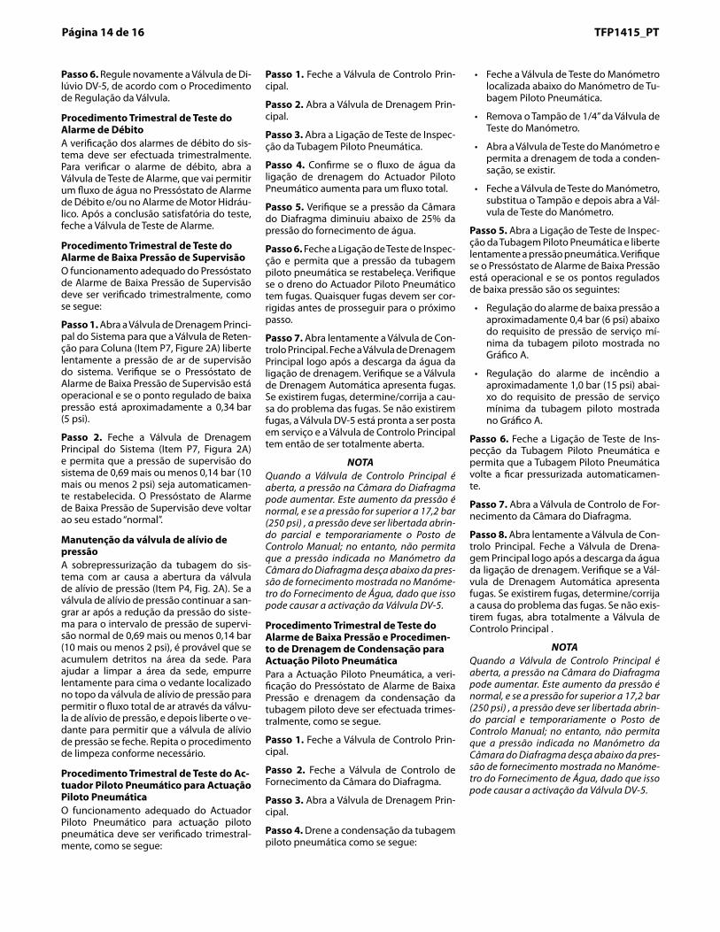
Step 2. Close the System Main DrainValve (Item P7, Figure 2A) and allowthe system supervisory pressure of 10plus or minus 2 psi (0,69 plus or minus0,14 bar) to be automatically re-estab-lished. The Supervisory Low PressureAlarm Switch should return to its “nor-mal” condition.
Pressure Relief Valve MaintenanceOver pressurization of the system pip-ing with air will result in the opening ofthe Pressure Relief Valve (Item P4,Fig. 2A). If the Relief Valve continuesto bleed air after the system pressurehas been reduced to its normal super-visory pressure range of 10 plus orminus 2 psi (0,69 plus or minus 0,14bar), most likely debris became lodgedin the seating area. To help clean theseating area, slowly pull up on the ringat the top of the Relief Valve to allow afull flow of air through the Relief Valve,and then release the ring to allow theRelief Valve to snap closed.Repeat thecleaning procedure as necessary.
Quarterly Dry Pilot Actuator TestProcedure For Dry Pilot ActuationProper operation of the Dry Pilot Ac-tuator for dry pilot actuation must beverified at least quarterly as follows:
Step 1. Close the Main Control Valve.
Step 2. Open the Main Drain Valve.
Step 3. Open the Inspector’s Test Con-nection on the Dry Pilot Line.
Step 4. Verify that the flow of waterfrom the Dry Pilot Actuator drain con-nection increases to a full flow.
Step 5. Verify that the DiaphragmChamber pressure has decreased tobelow 25% of the water supply pres-sure.
Step 6. Close the Inspector’s TestConnection and allow the dry pilot linepressure to re-establish. Check theDry Pilot Actuator drain for leaks. Anyleaks must be corrected before pro-ceeding to the next step.
Step 7. Slowly open the Main ControlValve. Close the Main Drain Valve assoon as water discharges from thedrain connection. Observe the Auto-matic Drain Valve for leaks. If there areleaks, determine/correct the cause ofthe leakage problem. If there are noleaks, the DV-5 Valve is ready to beplaced in service and the Main ControlValve must then be fully opened.
NOTEWhen the Main Control Valve isopened, the pressure on the Dia-phragm Chamber may increase. Thisincrease in pressure is normal, and ifthe pressure is greater than 250 psi(17,2 bar), the pressure is to be re-
lieved by partially and temporarilyopening the Manual Control Station;however, do not allow the pressure asindicated on the Diaphragm ChamberPressure Gauge to drop below thesupply pressure shown on the WaterSupply Pressure Gauge, since this ac-tion may result in tripping of the DV-5Valve.
Quarterly Low Pressure AlarmTest Procedure And CondensateDrain Procedure For Dry PilotActuationFor Dry Pilot Actuation, testing of theLow Pressure Alarm Switch and drain-age of the pilot line condensate mustbe performed quarterly as follows.
Step 1. Close the Main Control Valve.
Step 2. Close the Diaphragm Cham-ber Supply Control Valve.
Step 3. Open the Main Drain Valve.
Step 4. Drain the dry pilot line conden-sate as follows:
• Close the Gauge Test Valve locatedbelow the Dry Pilot Line PressureGauge.
• Remove the 1/4 inch Plug from theGauge Test Valve.
• Crack Open the Gauge Test Valveand allow all condensate, if any, todrain out.
• Close the Gauge Test Valve, re-place the Plug, and then open theGauge Test Valve.
Step 5. Open the Dry Pilot Line In-spector’s Test Connection, and slowlyrelieve pneumatic pressure. Verify thatthe Low Pressure Alarm Switch is op-erational and that the low pressure setpoints are as follows:
• Low pressure alarm setting at ap-proximately 6 psi (0,4 bar) below theminimum pilot line service pressurerequirement shown in Graph A.
• Fire alarm setting at approximately15 psi (1,0 bar) below the minimumpilot line service pressure require-ment shown in Graph A.
Step 6. Close the Dry Pilot Line In-spector’s Test Connection, and allowthe Dry Pilot Line to automatically re-pressurize.
Step 7. Open the Diaphragm ChamberSupply Control Valve.
Step 8. Slowly open the Main ControlValve. Close the Main Drain Valve assoon as water discharges from thedrain connection. Observe the Auto-matic Drain Valve for leaks. If there areleaks, determine/correct the cause ofthe leakage problem. If there are no
leaks, fully open the Main ControlValve.
NOTEWhen the Main Control Valve isopened, the pressure on the Dia-phragm Chamber may increase. Thisincrease in pressure is normal, and ifthe pressure is greater than 250 psi(17,2 bar), the pressure is to be re-lieved by partially and temporarilyopening the Manual Control Station;however, do not allow the pressure asindicated on the Diaphragm ChamberPressure Gauge to drop below thesupply pressure shown on the WaterSupply Pressure Gauge, since this ac-tion may result in tripping of the DV-5Valve.
Page 14 of 16 TFP1415Página 14 de 16 TFP1415_PT
Passo 6. Regule novamente a Válvula de Di-lúvio DV-5, de acordo com o Procedimento de Regulação da Válvula.
Procedimento Trimestral de Teste do Alarme de DébitoA verificação dos alarmes de débito do sis-tema deve ser efectuada trimestralmente. Para verificar o alarme de débito, abra a Válvula de Teste de Alarme, que vai permitir um fluxo de água no Pressóstato de Alarme de Débito e/ou no Alarme de Motor Hidráu-lico. Após a conclusão satisfatória do teste, feche a Válvula de Teste de Alarme.
Procedimento Trimestral de Teste do Alarme de Baixa Pressão de SupervisãoO funcionamento adequado do Pressóstato de Alarme de Baixa Pressão de Supervisão deve ser verificado trimestralmente, como se segue:
Passo 1. Abra a Válvula de Drenagem Princi-pal do Sistema para que a Válvula de Reten-ção para Coluna (Item P7, Figure 2A) liberte lentamente a pressão de ar de supervisão do sistema. Verifique se o Pressóstato de Alarme de Baixa Pressão de Supervisão está operacional e se o ponto regulado de baixa pressão está aproximadamente a 0,34 bar (5 psi).
Passo 2. Feche a Válvula de Drenagem Principal do Sistema (Item P7, Figura 2A) e permita que a pressão de supervisão do sistema de 0,69 mais ou menos 0,14 bar (10 mais ou menos 2 psi) seja automaticamen-te restabelecida. O Pressóstato de Alarme de Baixa Pressão de Supervisão deve voltar ao seu estado “normal”.
Manutenção da válvula de alívio de pressãoA sobrepressurização da tubagem do sis-tema com ar causa a abertura da válvula de alívio de pressão (Item P4, Fig. 2A). Se a válvula de alívio de pressão continuar a san-grar ar após a redução da pressão do siste-ma para o intervalo de pressão de supervi-são normal de 0,69 mais ou menos 0,14 bar (10 mais ou menos 2 psi), é provável que se acumulem detritos na área da sede. Para ajudar a limpar a área da sede, empurre lentamente para cima o vedante localizado no topo da válvula de alívio de pressão para permitir o fluxo total de ar através da válvu-la de alívio de pressão, e depois liberte o ve-dante para permitir que a válvula de alívio de pressão se feche. Repita o procedimento de limpeza conforme necessário.
Procedimento Trimestral de Teste do Ac-tuador Piloto Pneumático para Actuação Piloto Pneumática O funcionamento adequado do Actuador Piloto Pneumático para actuação piloto pneumática deve ser verificado trimestral-mente, como se segue:
Passo 1. Feche a Válvula de Controlo Prin-cipal.
Passo 2. Abra a Válvula de Drenagem Prin-cipal.
Passo �. Abra a Ligação de Teste de Inspec-ção da Tubagem Piloto Pneumática.
Passo 4. Confirme se o fluxo de água da ligação de drenagem do Actuador Piloto Pneumático aumenta para um fluxo total.
Passo 5. Verifique se a pressão da Câmara do Diafragma diminuiu abaixo de 25% da pressão do fornecimento de água.
Passo 6. Feche a Ligação de Teste de Inspec-ção e permita que a pressão da tubagem piloto pneumática se restabeleça. Verifique se o dreno do Actuador Piloto Pneumático tem fugas. Quaisquer fugas devem ser cor-rigidas antes de prosseguir para o próximo passo.
Passo �. Abra lentamente a Válvula de Con-trolo Principal. Feche a Válvula de Drenagem Principal logo após a descarga da água da ligação de drenagem. Verifique se a Válvula de Drenagem Automática apresenta fugas. Se existirem fugas, determine/corrija a cau-sa do problema das fugas. Se não existirem fugas, a Válvula DV-5 está pronta a ser posta em serviço e a Válvula de Controlo Principal tem então de ser totalmente aberta.
NOTA Quando a Válvula de Controlo Principal é aberta, a pressão na Câmara do Diafragma pode aumentar. Este aumento da pressão é normal, e se a pressão for superior a 17,2 bar (250 psi) , a pressão deve ser libertada abrin-do parcial e temporariamente o Posto de Controlo Manual; no entanto, não permita que a pressão indicada no Manómetro da Câmara do Diafragma desça abaixo da pres-são de fornecimento mostrada no Manóme-tro do Fornecimento de Água, dado que isso pode causar a activação da Válvula DV-5.
Procedimento Trimestral de Teste do Alarme de Baixa Pressão e Procedimen-to de Drenagem de Condensação para Actuação Piloto Pneumática Para a Actuação Piloto Pneumática, a veri-ficação do Pressóstato de Alarme de Baixa Pressão e drenagem da condensação da tubagem piloto deve ser efectuada trimes-tralmente, como se segue.
Passo 1. Feche a Válvula de Controlo Prin-cipal.
Passo 2. Feche a Válvula de Controlo de Fornecimento da Câmara do Diafragma.
Passo �. Abra a Válvula de Drenagem Prin-cipal.
Passo 4. Drene a condensação da tubagem piloto pneumática como se segue:
• Feche a Válvula de Teste do Manómetro localizada abaixo do Manómetro de Tu-bagem Piloto Pneumática.
• Remova o Tampão de 1/4” da Válvula de Teste do Manómetro.
• Abra a Válvula de Teste do Manómetro e permita a drenagem de toda a conden-sação, se existir.
• Feche a Válvula de Teste do Manómetro, substitua o Tampão e depois abra a Vál-vula de Teste do Manómetro.
Passo 5. Abra a Ligação de Teste de Inspec-ção da Tubagem Piloto Pneumática e liberte lentamente a pressão pneumática. Verifique se o Pressóstato de Alarme de Baixa Pressão está operacional e se os pontos regulados de baixa pressão são os seguintes:
• Regulação do alarme de baixa pressão a aproximadamente 0,4 bar (6 psi) abaixo do requisito de pressão de serviço mí-nima da tubagem piloto mostrada no Gráfico A.
• Regulação do alarme de incêndio a aproximadamente 1,0 bar (15 psi) abai-xo do requisito de pressão de serviço mínima da tubagem piloto mostrada no Gráfico A.
Passo 6. Feche a Ligação de Teste de Ins-pecção da Tubagem Piloto Pneumática e permita que a Tubagem Piloto Pneumática volte a ficar pressurizada automaticamen-te.
Passo �. Abra a Válvula de Controlo de For-necimento da Câmara do Diafragma.
Passo �. Abra lentamente a Válvula de Con-trolo Principal. Feche a Válvula de Drena-gem Principal logo após a descarga da água da ligação de drenagem. Verifique se a Vál-vula de Drenagem Automática apresenta fugas. Se existirem fugas, determine/corrija a causa do problema das fugas. Se não exis-tirem fugas, abra totalmente a Válvula de Controlo Principal .
NOTA Quando a Válvula de Controlo Principal é aberta, a pressão na Câmara do Diafragma pode aumentar. Este aumento da pressão é normal, e se a pressão for superior a 17,2 bar (250 psi) , a pressão deve ser libertada abrin-do parcial e temporariamente o Posto de Controlo Manual; no entanto, não permita que a pressão indicada no Manómetro da Câmara do Diafragma desça abaixo da pres-são de fornecimento mostrada no Manóme-tro do Fornecimento de Água, dado que isso pode causar a activação da Válvula DV-5.
LimitedWarrantyProducts manufactured by Tyco FireProducts are warranted solely to theoriginal Buyer for ten (10) yearsagainst defects in material and work-manship when paid for and properlyinstalled and maintained under normaluse and service. This warranty will ex-pire ten (10) years from date of ship-ment by Tyco Fire Products. No war-ranty is given for products orcomponents manufactured by compa-nies not affiliated by ownership withTyco Fire Products or for products andcomponents which have been subjectto misuse, improper installation, corro-sion, or which have not been installed,maintained, modified or repaired in ac-cordance with applicable Standards ofthe National Fire Protection Associa-tion, and/or the standards of any otherAuthorities Having Jurisdiction. Mate-rials found by Tyco Fire Products to bedefective shall be either repaired orreplaced, at Tyco Fire Products’ soleoption. Tyco Fire Products neither as-sumes, nor authorizes any person toassume for it, any other obligation inconnection with the sale of products orparts of products. Tyco Fire Productsshall not be responsible for sprinklersystem design errors or inaccurate orincomplete information supplied byBuyer or Buyer’s representatives.
IN NO EVENT SHALL TYCO FIREPRODUCTS BE LIABLE, IN CON-TRACT, TORT, STRICT LIABILITY ORUNDER ANY OTHER LEGAL THE-ORY, FOR INCIDENTAL, INDIRECT,SPECIAL OR CONSEQUENTIALDAMAGES, INCLUDING BUT NOTLIMITED TO LABOR CHARGES, RE-GARDLESS OF WHETHER TYCOFIRE PRODUCTS WAS INFORMEDABOUT THE POSSIBILITY OF SUCHDAMAGES, AND IN NO EVENTSHALL TYCO FIRE PRODUCTS’ LI-ABILITY EXCEED AN AMOUNTEQUAL TO THE SALES PRICE.
THE FOREGOING WARRANTY ISMADE IN LIEU OF ANY AND ALLOTHER WARRANTIES EXPRESS ORIMPLIED, INCLUDING WARRANTIESOF MERCHANTABILITY AND FIT-NESS FOR A PARTICULAR PUR-POSE.
OrderingProcedureWith reference to Table A on Page 16,the following items must be orderedseparately:
• Deluge Valve• Riser Check Valve• Coupling (Deluge Valve to Riser
Check Valve)• Single Interlock Preaction Trim• Supervisory Air Supply• Dry Pilot Air Supply• Accessories
NOTE1-1/2 inch (DN40) risers utilize a 2 inch(DN50) Riser Check Valve in combina-tion with the 1-1/2 inch (DN40) ModelDV-5 Deluge Valve.
Part Numbers for factory pre-trimmedModel DV-5 Valves are provided in thePrice Book.
Replacement Trim Parts:Specify: (description) for use withModel DV-5 Deluge Valve, P/N (seeFigure 2A).
Page 15 of 16TFP1415TFP1415_PT Página 15 de 16
Garantia LimitadaOs produtos fabricados pela Tyco Fire Pro-ducts são garantidos apenas ao Comprador original durante dez (10) anos contra defei-tos de fabrico e de material quando pagos, correctamente instalados e mantidos em condições normais de utilização e serviço. Esta garantia expira dez (10) anos após a data de envio pela Tyco Fire Products. Não é dada nenhuma garantia para produtos ou componentes fabricados por empresas não afiliadas por propriedade com a Tyco Fire Products ou para produtos e componen-tes que tenham sido sujeitos a utilização incorrecta, instalação incorrecta, corrosão ou que não tenham sido instalados, man-tidos, modificados ou reparados de acordo com as normas aplicáveis da NFPA, e/ou as normas de outras Autoridades Competen-tes. Os materiais considerados defeituosos pela Tyco Fire Products serão reparados ou substituídos, à descrição exclusiva da Tyco Fire Products. A Tyco Fire Products não as-sume, nem autoriza ninguém a assumir por si, qualquer obrigação relativa à venda de produtos ou peças de produtos. A Tyco Fire Products não será responsável por erros de projecção do sistema de sprinklers ou de informações imprecisas ou incorrectas for-necidas pelo Comprador ou representantes do mesmo.
EM CASO ALGUM SERÁ A TYCO FIRE PRO-DUCTS RESPONSÁVEL, POR CONTRATO, DA-NOS, RESPONSABILIDADE CIVIL OU QUAL-QUER OUTRA TEORIA LEGAL, POR DANOS ACIDENTAIS, INDIRECTOS, ESPECIAIS OU CONSEQUENCIAIS, INCLUINDO MAS NÃO LIMITADO A TAXAS DE MÃO-DE-OBRA, IN-DEPENDENTEMENTE SE A TYCO FIRE PRO-DUCTS ESTAVA OU NÃO INFORMADA DA POSSIBILIDADE DE TAIS DANOS, E EM CASO ALGUM A RESPONSABILIDADE DA TYCO FIRE PRODUCTS EXCEDERÁ UM MONTANTE IGUAL AO PREÇO DE VENDA.
A GARANTIA PRECEDENTE SUBSTITUI TO-DAS AS OUTRAS GARANTIAS, EXPRESSAS OU IMPLÍCITAS, INCLUINDO QUAISQUER GARANTIAS DE COMERCIALIZAÇÃO E ADEQUAÇÃO A UM DETERMINADO FIM.
Procedimento de EncomendaCom referência à Tabela A na Página 16, os seguintes itens devem ser encomendados separadamente:
• Válvula de Dilúvio • Válvula de Retenção para Coluna • Junção (Válvula de Dilúvio para Válvula
de Retenção para Coluna) • Acessórios de Pré-acção de Interblo-
queio Simples • Fornecimento de Ar de Supervisão • Fornecimento de Ar do Piloto Pneumá-
tico • Acessórios
NOTA Os tubos de extensão DN40 (1-1/2”) utilizam uma Válvula de Retenção para Coluna DN50 (/2”) em conjunto com a Válvula de Dilúvio DN40 (1-1/2”) Modelo DV-5.
Os Números de Peças para Válvulas Modelo DV-5 pré-montadas de fábrica são forneci-dos no Livro de Preços.
Peças de substituição dos acessórios: Especifique: (descrição) para utilizar com Válvula de Dilúvio Modelo DV-5, P/N (con-sulte Figura 2A).
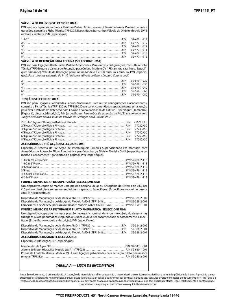
Page 16 of 16 TFP1415
TYCO FIRE PRODUCTS, 451 North Cannon Avenue, Lansdale, Pennsylvania 19446
DELUGE VALVE (SELECT ONE)P/N’s are for American Standard Groove x Groove Connections, and Threaded Ports, Forother configurations refer to Technical Data Sheet TFP1305. Specify: (size) Model DV-5groove x groove Deluge Valve, P/N (specify).
1-1/2 Inch . . . . . . . . . . . . . . . . . . . . . . . . . . . . . . . . . . . . . . . . . . . . . . . . . . . . . . . . . . P/N 52-477-1-9192 Inch . . . . . . . . . . . . . . . . . . . . . . . . . . . . . . . . . . . . . . . . . . . . . . . . . . . . . . . . . . . . . P/N 52-477-1-9103 Inch . . . . . . . . . . . . . . . . . . . . . . . . . . . . . . . . . . . . . . . . . . . . . . . . . . . . . . . . . . . . . P/N 52-477-1-9124 Inch . . . . . . . . . . . . . . . . . . . . . . . . . . . . . . . . . . . . . . . . . . . . . . . . . . . . . . . . . . . . . P/N 52-477-1-9136 Inch . . . . . . . . . . . . . . . . . . . . . . . . . . . . . . . . . . . . . . . . . . . . . . . . . . . . . . . . . . . . . P/N 52-477-1-9158 Inch . . . . . . . . . . . . . . . . . . . . . . . . . . . . . . . . . . . . . . . . . . . . . . . . . . . . . . . . . . . . . P/N 52-477-1-916
RISER CHECK VALVE (SELECT ONE)P/N’s are for American Standard Grooved Connections. For other configurations refer toTechnical Data Sheet TFP950 for the groove x groove Model CV1-FR Riser Check Valve.Specify: (size), Model CV-1FR groove x groove Riser Check Valve, P/N (specify). For 1-1/2inch risers, use the 2 Inch Riser Check Valve.
2 Inch . . . . . . . . . . . . . . . . . . . . . . . . . . . . . . . . . . . . . . . . . . . . . . . . . . . . . . . . . . . . . P/N 59-590-1-0203 Inch . . . . . . . . . . . . . . . . . . . . . . . . . . . . . . . . . . . . . . . . . . . . . . . . . . . . . . . . . . . . . P/N 59-590-1-0304 Inch . . . . . . . . . . . . . . . . . . . . . . . . . . . . . . . . . . . . . . . . . . . . . . . . . . . . . . . . . . . . . P/N 59-590-1-0406 Inch . . . . . . . . . . . . . . . . . . . . . . . . . . . . . . . . . . . . . . . . . . . . . . . . . . . . . . . . . . . . . P/N 59-590-1-0608 Inch . . . . . . . . . . . . . . . . . . . . . . . . . . . . . . . . . . . . . . . . . . . . . . . . . . . . . . . . . . . . . P/N 59-590-1-080
COUPLING (SELECT ONE)P/N’s are for American Standard Grooved Connections. For other configurations andfinishes refer to Technical Data Sheet TFP1830 or TFP1880. A coupling to attach theRiser Check Valve to the outlet of the Deluge Valve must be separately ordered. Specify:(Size), (Figure #), painted, (description), P/N (specify). For 1-1/2 inch risers, order anadditional Reducing Coupling for the outlet of the 2 inch Riser Check Valve.
2 x 1-1/2 Inch Figure 716 Painted Reducing Coupling. . . . . . . . . . . . . . . . . . . . . . . P/N 7162015ES2 Inch Figure 772 Painted Rigid Coupling . . . . . . . . . . . . . . . . . . . . . . . . . . . . . . . . P/N 77220ASC3 Inch Figure 772 Painted Rigid Coupling . . . . . . . . . . . . . . . . . . . . . . . . . . . . . . . . P/N 77230ASC4 Inch Figure 772 Painted Rigid Coupling . . . . . . . . . . . . . . . . . . . . . . . . . . . . . . . . P/N 77240ASC6 Inch Figure 772 Painted Rigid Coupling . . . . . . . . . . . . . . . . . . . . . . . . . . . . . . . . P/N 77260ASC8 Inch Figure 772 Painted Rigid Coupling . . . . . . . . . . . . . . . . . . . . . . . . . . . . . . . . P/N 77280ASC
PREACTION TRIM (SELECT ONE)Specify: (specify size and finish — galvanized is standard) Semi-Preassembled Super-vised Single Interlock Preaction System With Dry Pilot Actuation Trim for Model DV-5Deluge Valves, P/N (specify).
1-1/2 & 2 Inch Galvanized . . . . . . . . . . . . . . . . . . . . . . . . . . . . . . . . . . . . . . . . . . . . . P/N 52-478-2-1181-1/2 & 2 Inch Black . . . . . . . . . . . . . . . . . . . . . . . . . . . . . . . . . . . . . . . . . . . . . . . . . . P/N 52-478-1-1183 Inch Galvanized. . . . . . . . . . . . . . . . . . . . . . . . . . . . . . . . . . . . . . . . . . . . . . . . . . . . P/N 52-478-2-1153 Inch Black . . . . . . . . . . . . . . . . . . . . . . . . . . . . . . . . . . . . . . . . . . . . . . . . . . . . . . . . P/N 52-478-1-1154, 6 & 8 Inch Galvanized . . . . . . . . . . . . . . . . . . . . . . . . . . . . . . . . . . . . . . . . . . . . . . P/N 52-478-2-1124, 6 & 8 Inch Black . . . . . . . . . . . . . . . . . . . . . . . . . . . . . . . . . . . . . . . . . . . . . . . . . . . P/N 52-478-1-112
SUPERVISORY AIR SUPPLY (SELECT ONE)A device capable of maintaining a nominal system air or nitrogen pressure of nominal 10psi (0,69 bar) must be separately ordered. Specify: (Specify model and description), P/N(specify).
Model AMD-1 Air Maintenance Device (TFP1221) . . . . . . . . . . . . . . . . . . . . . . . . . P/N 52-324-2-002Model AMD-3 Nitrogen Maintenance Device (TFP1241) . . . . . . . . . . . . . . . . . . . . P/N 52-328-2-001Model G16AC812 Automatic Supervisory Air Supply (TD126) . . . . . . . . . . . . . . . . P/N 52-150-1-001
DRY PILOT LINE AIR SUPPLY (SELECT ONE)A device capable of maintaining the required nominal system air or nitrogen pressurewithin the dry pilot lines per Graph A must be separately ordered. Specify: (Specify modeland description), P/N (specify).
Model AMD-1 Air Maintenance Device (TFP1221) . . . . . . . . . . . . . . . . . . . . . . . . . P/N 52-324-2-002Model AMD-2 Air Maintenance Device (TFP1231) . . . . . . . . . . . . . . . . . . . . . . . . . P/N 52-326-2-001Model AMD-3 Nitrogen Maintenance Device (TFP1241) . . . . . . . . . . . . . . . . . . . . P/N 52-328-2-001
ACCESSORIES (AS NEEDED)Specify: (description), PN (specify).
600 PSI Water Pressure Gauge . . . . . . . . . . . . . . . . . . . . . . . . . . . . . . . . . . . . . . . . P/N 92-343-1-004Model WMA-1 Water Motor Alarm (TFP921) . . . . . . . . . . . . . . . . . . . . . . . . . . . . . . P/N 52-630-1-001Model MC-1 Manual Control Stations with
galvanized connections for remote dry pilot actuation (TFP1382). . . . . . . . . . . P/N 52-289-2-001
TABLE A — ORDERING LIST
TYCO FIRE PRODUCTS, 451 North Cannon Avenue, Lansdale, Pennsylvania 19446
Página 16 de 16 TFP1415_PT
Nota: Este documento é uma tradução. A tradução de materiais em idiomas que não o Inglês destina-se unicamente a facilitar a leitura do público não Inglês. A precisão da tra-dução não está garantida nem implícita. Se tiver dúvidas relativas à precisão das informações contidas na tradução, consulte a versão em Inglês do documento TFP1415, que é a versão oficial do documento. Quaisquer discrepâncias ou diferenças criadas na tradução não são vinculativas e não têm quaisquer efeitos legais relativamente a conformidade,
cumprimento ou quaisquer outros fins. www.quicksilvertranslate.com.
VÁLVULA DE DILÚVIO (SELECCIONE UMA)P/N são para Ligações Ranhura x Ranhura Padrão Americanas e Orifícios de Rosca. Para outras confi-gurações, consulte a Ficha Técnica TFP1305. Especifique: [tamanho] Válvula de Dilúvio Modelo DV-5 ranhura x ranhura, P/N [especifique].
1-1/2 “ . . . . . . . . . . . . . . . . . . . . . . . . . . . . . . . . . . . . . . . . . . . . . . . . . . . . . . . . . . . . . . . . . . . . . . . . . . . . . P/N 52-477-1-9192 “ . . . . . . . . . . . . . . . . . . . . . . . . . . . . . . . . . . . . . . . . . . . . . . . . . . . . . . . . . . . . . . . . . . . . . . . . . . . . . . . . . P/N 52-477-1-9103 “ . . . . . . . . . . . . . . . . . . . . . . . . . . . . . . . . . . . . . . . . . . . . . . . . . . . . . . . . . . . . . . . . . . . . . . . . . . . . . . . . . P/N 52-477-1-9124 “ . . . . . . . . . . . . . . . . . . . . . . . . . . . . . . . . . . . . . . . . . . . . . . . . . . . . . . . . . . . . . . . . . . . . . . . . . . . . . . . . . P/N 52-477-1-9136 “ . . . . . . . . . . . . . . . . . . . . . . . . . . . . . . . . . . . . . . . . . . . . . . . . . . . . . . . . . . . . . . . . . . . . . . . . . . . . . . . . . P/N 52-477-1-9158 “ . . . . . . . . . . . . . . . . . . . . . . . . . . . . . . . . . . . . . . . . . . . . . . . . . . . . . . . . . . . . . . . . . . . . . . . . . . . . . . . . . P/N 52-477-1-916
VÁLVULA DE RETENÇÃO PARA COLUNA (SELECCIONE UMA)P/N são para Ligações Ranhuradas Padrão Americanas. Para outras configurações, consulte a Ficha Técnica TFP950 para a Válvula de Retenção para Coluna Modelo CV-1FR ranhura x ranhura. Especifi-que: [tamanho], Válvula de Retenção para Coluna Modelo CV-1FR ranhura x ranhura, P/N [especifi-que]. Para tubos de extensão de 1-1/2“, utilize a Válvula de Retenção para Coluna de 2“.
2 “ . . . . . . . . . . . . . . . . . . . . . . . . . . . . . . . . . . . . . . . . . . . . . . . . . . . . . . . . . . . . . . . . . . . . . . . . . . . . . . . . P/N 59-590-1-0203 “ . . . . . . . . . . . . . . . . . . . . . . . . . . . . . . . . . . . . . . . . . . . . . . . . . . . . . . . . . . . . . . . . . . . . . . . . . . . . . . . . P/N 59-590-1-0304 “ . . . . . . . . . . . . . . . . . . . . . . . . . . . . . . . . . . . . . . . . . . . . . . . . . . . . . . . . . . . . . . . . . . . . . . . . . . . . . . . . . P/N 59-590-1-0406 “ . . . . . . . . . . . . . . . . . . . . . . . . . . . . . . . . . . . . . . . . . . . . . . . . . . . . . . . . . . . . . . . . . . . . . . . . . . . . . . . . . P/N 59-590-1-0608 “ . . . . . . . . . . . . . . . . . . . . . . . . . . . . . . . . . . . . . . . . . . . . . . . . . . . . . . . . . . . . . . . . . . . . . . . . . . . . . . . . P/N 59-590-1-080
JUNÇÃO (SELECCIONE UMA)P/N são para Ligações Ranhuradas Padrão Americanas. Para outras configurações e acabamentos, consulte a Ficha Técnica TFP1830 ou TFP1880. Deve ser encomendada separadamente uma junção para fixar a Válvula de Retenção para Coluna à saída da Válvula de Dilúvio. Especifique: [Tamanho], [Figura #], pintura, [descrição], P/N [especifique]. Para tubos de extensão de 1-1/2”, encomende uma Junção Redutora para a saída da Válvula de Retenção para Coluna de 2”.
2 x 1-1/2” Figura 716 Junção Redutora Pintada. . . . . . . . . . . . . . . . . . . . . . . . . . . . . . . . . . . . . . . . . P/N 7162015ES2” Figura 772 Junção Rígida Pintada . . . . . . . . . . . . . . . . . . . . . . . . . . . . . . . . . . . . . . . . . . . . . . . . . . . P/N 77220ASC3” Figura 772 Junção Rígida Pintada . . . . . . . . . . . . . . . . . . . . . . . . . . . . . . . . . . . . . . . . . . . . . . . . . . . P/N 77230ASC4” Figura 772 Junção Rígida Pintada . . . . . . . . . . . . . . . . . . . . . . . . . . . . . . . . . . . . . . . . . . . . . . . . . . . P/N 77240ASC6” Figura 772 Junção Rígida Pintada . . . . . . . . . . . . . . . . . . . . . . . . . . . . . . . . . . . . . . . . . . . . . . . . . . . P/N 77260ASC8” Figura 772 Junção Rígida Pintada . . . . . . . . . . . . . . . . . . . . . . . . . . . . . . . . . . . . . . . . . . . . . . . . . . . P/N 77280ASC
ACESSÓRIOS DE PRÉ-ACÇÃO (SELECCIONE UM)Especifique: Sistema de Pré-acção de Interbloqueio Simples Supervisionado Pré-montado com Acessórios de Actuação Piloto Pneumática para Válvulas de Dilúvio Modelo DV-5, [especifique ta-manho e acabamento - galvanizado é padrão], P/N [especifique].
1-1/2 & 2” Galvanizado . . . . . . . . . . . . . . . . . . . . . . . . . . . . . . . . . . . . . . . . . . . . . . . . . . . . . . . . . . . . . . . P/N 52-478-2-1181-1/2 & 2” Preto . . . . . . . . . . . . . . . . . . . . . . . . . . . . . . . . . . . . . . . . . . . . . . . . . . . . . . . . . . . . . . . . . . . . . . . P/N 52-478-1-1183” Galvanizado . . . . . . . . . . . . . . . . . . . . . . . . . . . . . . . . . . . . . . . . . . . . . . . . . . . . . . . . . . . . . . . . . . . . . . . P/N 52-478-2-1153” Preto . . . . . . . . . . . . . . . . . . . . . . . . . . . . . . . . . . . . . . . . . . . . . . . . . . . . . . . . . . . . . . . . . . . . . . . . . . . . . . P/N 52-478-1-1154, 6 & 8” Galvanizado. . . . . . . . . . . . . . . . . . . . . . . . . . . . . . . . . . . . . . . . . . . . . . . . . . . . . . . . . . . . . . . . . . P/N 52-478-2-1124, 6 & 8” Preto. . . . . . . . . . . . . . . . . . . . . . . . . . . . . . . . . . . . . . . . . . . . . . . . . . . . . . . . . . . . . . . . . . . . . . . . . P/N 52-478-1-112
FORNECIMENTO DE AR DE SUPERVISÃO (SELECCIONE UM)Um dispositivo capaz de manter uma pressão nominal de ar ou nitrogénio de sistema de 0,69 bar (10 psi) nominal deve ser encomendado em separado. Especifique: [Especifique modelo e descri-ção], P/N [especifique].
Dispositivo de Manutenção de Ar Modelo AMD-1 (TFP1221) . . . . . . . . . . . . . . . . . . . . . . . . . . . P/N 52-324-2-002Dispositivo de Manutenção de Nitrogénio Modelo AMD-3 (TFP1241). . . . . . . . . . . . . . . . . . . P/N 52-328-2-001Fornecimento de Ar de Supervisão Automático Modelo G16AC812 (TD126) . . . . . . . . . . . . P/N 52-150-1-001
FORNECIMENTO DE AR DE TUBAGEM PILOTO PNEUMÁTICA (SELECCIONE UM)Um dispositivo capaz de manter a pressão necessária nominal de ar ou nitrogénio do sistema nas tubagens piloto pneumáticas segundo o Gráfico A, deve ser encomendado separadamente. Especi-fique: (Especifique modelo e descrição), P/N (especifique).
Dispositivo de Manutenção de Ar Modelo AMD-1 (TFP1221) . . . . . . . . . . . . . . . . . . . . . . . . P/N 52-324-2-002Dispositivo de Manutenção de Ar Modelo AMD-2 (TFP1231) . . . . . . . . . . . . . . . . . . . . . . . . P/N 52-326-2-001Dispositivo de Manutenção de Nitrogénio Modelo AMD-3 (TFP1241). . . . . . . . . . . . . . . . P/N 52-328-2-001
ACESSÓRIOS (CONSOANTE NECESSÁRIO)Especifique: [descrição], NP [especifique].
Manómetro de Água 600 psi . . . . . . . . . . . . . . . . . . . . . . . . . . . . . . . . . . . . . . . . . . . . . . . . . . . . . . . . . .P/N 92-343-1-004Alarme de Motor Hidráulico Modelo WMA-1 (TFP921) . . . . . . . . . . . . . . . . . . . . . . . . . . . . . . . . . P/N 52-630-1-001Postos de Controlo Manual Modelo MC-1 com ligações galvanizadas para actuação piloto pneumática remota (TFP1382) . . . . . . . . . . . . . . . . . . . . . . . . . . . . . . . . . . . . . . . . . . . . . . . . . . . . . . . . . . . . . . . . . . . . P/N 52-289-2-001
TABELA A — LISTA DE ENCOMENDA