SIMULATION OF MICRO HYDRO POWER BASED ON RIVER ... · 2012 and ANSYS (CFX). Simulations have been...
24
SIMULATION OF MICRO HYDRO POWER BASED ON RIVER CONFIGURATION AT RIVER DOWNSTREAM SITI NOR SUZIYANA BINTI DOLLAH Thesis submitted to the department of the requirements for the award of the degree of Bachelor of Mechanical Engineering Faculty of Mechanical Engineering UNIVERSITI MALAYSIA PAHANG JUNE 2013
Transcript of SIMULATION OF MICRO HYDRO POWER BASED ON RIVER ... · 2012 and ANSYS (CFX). Simulations have been...

SIMULATION OF MICRO HYDRO POWER BASED ON RIVER
CONFIGURATION AT RIVER DOWNSTREAM
SITI NOR SUZIYANA BINTI DOLLAH
Thesis submitted to the department of the requirements
for the award of the degree of
Bachelor of Mechanical Engineering
Faculty of Mechanical Engineering
UNIVERSITI MALAYSIA PAHANG
JUNE 2013

vi
ABSTRACT
Micro hydro power convert potential energy of water into electricity and it a
clean source. The project present about Simulation of Micro Hydro Power based on
river configuration at river downstream. The objectives of this project to simulate flow
of downstream river for different Micro hydro power, to determine the performance
and efficiency of micro hydro power in downstream river and to determine the
availability of hydroelectric in rural areas. This project is focused on downstream river
where the velocity, pressure and topology data is to be determined. The place that used
for this project is Sungai Pahang. In this project just used two software, it is SolidWorks
2012 and ANSYS (CFX). Simulations have been done with two different turbine of
micro hydro power, the first turbine is Propeller and the second is Tidal turbine.
Between the two turbines the performance of Propeller turbine are good compared to
the tidal turbine. It is because the toque of Propeller is higher compared to the tidal. The
torque is 17.295Nm and 11.901Nm. As the conclusion propeller turbine are beater
compare to the tidal turbine.

vii
ABSTRAK
Kuasa mikro hidro mengubah tenaga keupayaan air kepada elektrik dan ia
merupakan sumber yang bersih. Projek ini adalah mengenai simualsi kuasa mikro hidro
berdasarkan konfigurasi di hilir sungai. Projek ini bertujuan untuk mensimulasikan
aliran sungai hilir dengan perbezaan mikro hidro, ia juga bertujuan untuk menentukn
kecekapan dan prestasi kuasa mikro hidro di hilir sungai dan ia juga bertujuan untuk
kesesuaian diguankan di kawasan luarbandar. Projek ini dikhususkan dihilir sungai
dimana kelajuan, tekanan perlu ditentukan. Tempat yang digunakan untuk projek ini
ialah Sungai Pahang. Projek ini mengunakan dua jenis perisisan iaitu SolidWorks 2012
dan ANSYS (CFX). Simulasi ini telah dilakukan kepada dua jenis turbin yang berbeza.
turbin pertama adalah Propeller dan kedua adalah Tidal.berdasarkan kedua-dua jenis
turbin, turbine Propeller lebih baik berbanding turbin Tidal. Ini kerana daya kilas untuk
turbin propeller lebih tinggi jika dibandingkan dengan turbin tidal. Daya kilas itu ialah
17.295 Nm dan 11.901 Nm. Kesimpulannya, turbin Propeller adalah lebih baik
dibandingkan dengan turbin Tidal.

viii
TABLE OF CONTENT
Page
EXAMINERS APPROVAL DOCUMENT i
SUPERVISOR’S DECLARATION ii
STUDENT DECLARATION iii
DEDICATION iv
ACKNOWLEDGEMENTS v
ABSTRACT vi
ABSTRAK vii
TABLE OF CONTENTS viii
LIST OD TABLE xi
LIST OF FIGURE xii
LIST OF SYMBOLS xiv
LIST OF ABBREVATION xv
CHAPTER 1 INTRODUCTION
1.1 Introduction 1
1.2 Problem Statements 2
1.3 Objectives 2
1.4 Scopes 3
CHAPTER 2 LITERATURE REVIEW
2.1 Introduction 4
2.2 General Principle of MHP 5
2.3 Power from a MHP 6
2.3.1 The losses in a hydro plant are 7
2.4 Component of MHP 8
2.4.1 Turbine 8
2.4.2 Generator 17
2.5 Advantage and disadvantage of MHP 19

ix
2.5.1 Advantage of Micro Hydro 19
2.5.2 Disadvantage of Micro Hydro 20
CHAPTER 3 METHODOLOGY
3.1 Introduction 22
3.2 Site Visit 22
3.2.1 Potential of MHP 25
3.3 Data collection 25
3.31 Propeller Turbine 26
3.3.2 Tidal Turbine 27
3.4 Design of turbine 28
3.4.1 Flow chart for turbine design 28
3.4.2 Design of turbine 29
3.5 Simulation of MHP 32
3.6 Setup of ANSYS CFX 33
3.6.1 Geometry 33
3.6.2 Meshing 34
3.6.3 Setup 35
3.6.4 Solution 36
3.7 Measure the power output 36
CHAPTER 4 RESULT AND DISCUSSION
4.1 Introduction 38
4.2 Simulation Result 38
4.2.1 CFX simulation Result 38
4.2.2 Data of performance of micro hydro power 41
4.3 Calculation of performance 44
CHAPTER 5 CONCLUSION AND RECOMMANDATION
5.1 Introduction 46
5.2 Micro Hydro Power system 46
5.3 Recommendations 46

x
REFERENCES 47
APPENDICES 48

xi
LIST OF TABLE
Table No. Title Page
2.1 Classification of hydropower by size 5
2.2 Classification of water head 5
2.3 Turbine Application 8
4.1 Data of simulation 41
4.2 Performance of Micro Hydro Power 42
xii
LIST OF FIGURE
Figure No. Title Page
2.1 A low head micro hydro installation 4
2.2 Pelton Turbine 10
2.3 Turgo Turbine 10
2.4 Cross flow Turbine 12
2.5 Francis Turbine 13
2.6 Francis Turbine Blade 14
2.7 Propeller Turbine 14
2.8 Kaplan Turbine 15
2.9 Kaplan efficiency curve comparison 16
2.10 Working System of Generator 17
3.1 Sungai Pahang 22
3.2 Sungai Pahang near to Kampung Pulau Tambun 23
3.3 Near to Pekan bridge 24
3.4 Turbine Application Chart 26
3.5 Propeller Turbine 27
3.6 Tidal Turbine 27
3.7 Flow chart for turbine design 28
3.8 Propeller Turbine Model 29
3.9 Isometric view for propeller turbine 30
3.10 Tidal turbine model 30
3.11 Isometric view for Tidal Turbine 31
3.12 Flow chart for simulation 32
3.13 Setup for CFX 33
3.14 Geometry 33
3.15 Mesh 34
3.16 Setup 35
3.17 Solution in Plane 36
4.1 Plane XY axis 39
4.2 Stream line 40
4.3 Velocity in line 41

xiii
4.4 Graph of power vs rotation speed 43
4.5 Graph of efficiency vs rotation speed 43
4.6 Graph efficiency vs power 44

xiv
LIST OF SYMBOLS
psi pound per square inch
gpm gallons per minute
m3/s cubic meters per second
lpm liters per minute
l/s liters per second
m/s meter per second
kW kilo watts
P power
ω angular velocity
τ torque
Α swapped area
ρ density
ν velocity
η efficiency

xv
LIST OF ABBREVATION
MHP Micro Hydro Power
JPS Jabatan Pengairan dan Saliran
AC Alternating Current
DC Direct Current
CHAPTER 1
INTRODUCTION
1.1 INTRODUCTION
Nowadays there are many sources that use to sustainable the energy for example
micro hydropower, solar energy, biomass, geothermal and etc. The energy is generating
from natural resources such as water, radiation, wind and tides etc. which are renewable
in nature. Hydro power plants convert potential energy of water into electricity and it is
a clean source. The water, after generating electrical power is available for irrigation
and purposes. A micro hydro power plant has a capacity of up to 100kW. Micro
hydroelectric power system can produce enough electricity for home, farm, ranch or
village. Hydroelectric power generated from water is not yet all tapped completely.
Micro hydro power plants are emerging as a major renewable energy resource today.
However, they require control system to limit the huge variation in input flow expected
in rivulets over which these are established so as to produce a constant power supply.
This also helps in achieving the competitive cost of generated power which is possible
by using hydro power. In planning of micro hydro power plant, it is necessary to
mention the power demand of that region. New micro Grid (MG) is to be introducing in
existing power system based on the local power supply conditions. Potential improve
the Self-supply Ratio (a percentage of the valid power obtained from local power
source) in power consumption. It should be considered that in the view of overall
condition of energy development, the potential power existing in the weak natural
2
energy regions usually ignored due to low benefit and long repayment period. In reality,
almost all parts of region in which people are living are usually with the natural energy.
World energy shortage points out that it becomes urgency to develop the weak natural
energy around local inhabitants. In economic analysis, it is found that the payback is
severely affected by the effective water- head that the water flow rate. It could be
observed that to select an irrigation canal with higher water head for installing mini
hydro power plant, it is more important than to select a canal with larger water flow
rate.
In this project, the simulations have done for micro hydro power at Sungai
Pahang. From this experiment the water flow into the turbine and then will rotate the
turbine, after that it will generate hydro power. After generation of power, it can use for
people that live at the area which is the people that live near to Jambatan Pekan. This
concept is useful to utilize untapped renewable energy. Various basic parameters such
as section of site, hydrological and topographical survey and its analysis is studied for
deciding the suitable micro hydro power.
1.2 PROBLEM STATEMENTS
Geographical factor play an important role in micro hydro power plant. The
height (head) of river, velocity of flow, water traffics, river contamination and topology
data differs in every place. These factors may affect the performance and efficiency of
micro hydro power. Different types of micro hydro power differ in performance and
efficiency. The effectiveness of micro hydro power is influenced by surrounding
factors.
1.3 OBJECTIVES
The main objective of this project is to simulate flow of downstream river for
different turbine in micro hydro power. There are two types of turbine which is
Propeller and tidal turbine.
3
Next objective is to determine the performance and efficiency of micro hydro
power in the downstream river configuration.
And the last objective is to determine the availability of micro hydro power in
the rural area.
1.4 SCOPES
The analysis that used in this project is for Sungai Pahang. This project focuses
on the downstream river configuration where the velocity, pressure and topology data is
to be determined.
This project is more focus on simulation of the micro hydro power. All parts in
the water turbine system have been done using SolidWorks 2012. Based on the data
collected, the simulations have been done using ANSYS (CFX). From the result
obtained, we can know the suitable micro hydro power based on higher performance.

CHAPTER 2
LITRTURE RIVIEW
2.1 INTRODUCTION
Following and falling water have potential energy. Hydro power comes from
converting energy in following water by means of water wheel or through a turbine into
useful mechanical power. This power is converted into electric using an electric
generator or is used directly to run milling machines.(DOE, 2001). Micro-hydro power
is the small-shale harnessing of energy from falling water; for example harnessing
enough water from a local river to power a small factory or village. This fact sheet will
concentrate mainly at micro-hydro power.
Figure 2.1: A low-head micro-hydro installation
Source: Fraenkel et al(1991)
5
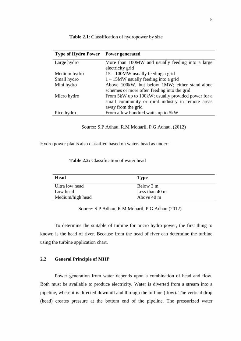
Table 2.1: Classification of hydropower by size
Type of Hydro Power Power generated
Large hydro More than 100MW and usually feeding into a large
electricity grid
Medium hydro 15 – 100MW usually feeding a grid
Small hydro 1 – 15MW usually feeding into a grid
Mini hydro Above 100kW, but below 1MW; either stand-alone
schemes or more often feeding into the grid
Micro hydro From 5kW up to 100kW; usually provided power for a
small community or rural industry in remote areas
away from the grid
Pico hydro From a few hundred watts up to 5kW
Source: S.P Adhau, R.M Moharil, P.G Adhau, (2012)
Hydro power plants also classified based on water- head as under:
Table 2.2: Classification of water head
Head Type
Ultra low head Below 3 m
Low head Less than 40 m
Medium/high head Above 40 m
Source: S.P Adhau, R.M Moharil, P.G Adhau (2012)
To determine the suitable of turbine for micro hydro power, the first thing to
known is the head of river. Because from the head of river can determine the turbine
using the turbine application chart.
2.2 General Principle of MHP
Power generation from water depends upon a combination of head and flow.
Both must be available to produce electricity. Water is diverted from a stream into a
pipeline, where it is directed downhill and through the turbine (flow). The vertical drop
(head) creates pressure at the bottom end of the pipeline. The pressurized water
6
emerging from the end of the pipe creates the force that drives the turbine. The turbine
in turn drives the generator where electrical power is produced. More flow or more head
produces more electricity. Electrical power output will always be slightly less than
water power input due to turbine and system inefficiencies.
Water pressure or Head is created by the difference in elevation between the
water intake and the turbine. Head can be expressed as vertical distance (feet or meters),
or as pressure, such as pounds per square inch (psi). Net head is the pressure available at
the turbine when water is flowing, which will always be less than the pressure when the
water flow is turned off (static head), due to the friction between the water and the pipe.
Pipeline diameter also has an effect on net head.
Flow is quantity of water available, and is expressed as ‘volume per unit of
time’, such as gallons per minute (gpm), cubic metres per second (m3/s), or liters per
minute (lpm). Design flow is the maximum flow for which the hydro system is
designed. It will likely be less than the maximum flow of the stream (especially during
the rainy season), more than the minimum flow, and a compromise between potential
electrical output and system cost (Singh.D, 2009)
2.3 Power from a MHP
To know the power potential of water in a stream it is necessary to know the
flow quantity of water available from the stream (for power generation) and the
available head.
The quantity of water available for power generation is the amount of water (in
m3or litres) which can be diverted through an intake into the pipeline (penstock) in a
certain amount of time. This is normally expressed in cubic meters per second (m3/s) or
in litres per second (l/s).
Head is the vertical difference in level (in meters) through which the water falls
down.
7
The theoretical power (P) available from a given head of water is in exact
proportion to the head and the quantity of water available.
P= Q × H × e × 9.81 Kilowatts (kW) (1)
Where,
P =Power at the generator terminal, in kilowatts (kW)
H =The gross head from the pipeline intake to the tail water in metres (m)
Q =Flow in pipeline, in cubic metres per second (m3/s)
e =The efficiency of the plant, considering head loss in the pipeline and the efficiency
of the turbine and generator, expressed by a decimal (e.g. 85% efficiency= 0.85) 9.81 is
a constant and is the product of the density of water and the acceleration due to gravity
(g) (Singh D, 2009)
This available power will be converted by the hydro turbine in mechanical power.
2.3.1 The losses in a hydro plant are
Losses in energy caused by flow disturbances at the intake to the pipeline,
friction in the pipeline, and further flow disturbances at valves and bends; and loss of
power caused by friction and design inefficiencies in the turbine and generator.
The energy losses in the pipeline and at valves and bends are called head losses:
they represent the difference between the gross head and the net head that is available at
the turbine. The head losses in the pipeline could range from 2 percent to 10 percent of
the gross head, depending on the length of the pipeline and the velocity of the flow. The
maximum turbine efficiency could range from 80 percent to 95 percent depending on
the type of turbine, and the generator efficiency will be about 90 percent.
Usually for design purposes, the head losses can be combined with the losses in
the turbine and generator, and an overall plant efficiency of 85 percent (or e = 0.85) can
be used. (Singh. D, 2009)

8
2.4 Component of MHP
2.4.1 Turbine
Turbine is the main piece of equipment in the MHP scheme that converts energy
of the falling water into the rotating shaft power. The selection of the most suitable
turbine for any particular hydro site depends mainly on two of the site characteristics –
head and flow available. All turbines have a power-speed characteristic. This means
they will operate most efficiently at a particular speed, head and flow combination.
Thus the desired running speed of the generator or the devices being connected/ loading
on to the turbine also influence selection. Other important consideration is whether the
turbine is expected to generate power at part-flow conditions.
The design speed of a turbine is largely determined by the head under which it
operates. Turbines can be classified as high head, medium head or low head machines.
They are also typified by the operating principle and can be either impulse or reaction
turbines. The basic turbine classification is given in the table below:
Table 2.3: Turbine application
Turbine Head (Pressure)
High (30m +) Medium Low (<10m)
Impulse Pelton
Turgo
Cross flow
Pelton
Turgo
Cross flow
Reaction - Francis
Pump
Propeller
Darius
Source: Singh, D. 2009
Impulse Turbine, which has the least complex design, is most commonly used
for high-head micro hydro systems. They rely on the velocity of water to move the
turbine wheel, which is called the runner. The most common types of impulse turbines
include the Pelton wheel and the Turgo wheel.

9
Difference between impulse and reaction turbines
The rotating part (called ‘runner’) of a reaction turbine is completely submerged
in water and is enclosed in a pressure casing. The runner blades are designed in a
manner such that the pressure difference across their surface imposes lift forces (similar
to the principle used for airplane wings) which cause the runner to turn/rotate.
The impulse turbine (as the name suggests) on the other hand is never immersed
in water but operates in air, driven by a jet (or jets) of water striking its blades. The
nozzle of the penstock converts the head of the water (from forebear tank) into a high
speed jet that hits the turbine runner blades that deflect the jet so as to utilize the change
of momentum of the water and converting this as the force on the blades – enabling it to
rotate.
Impulse turbines are usually cheaper than reaction turbines because there is no
need for a pressure casing nor for carefully engineered clearances, but they are also only
suitable for relatively higher heads.
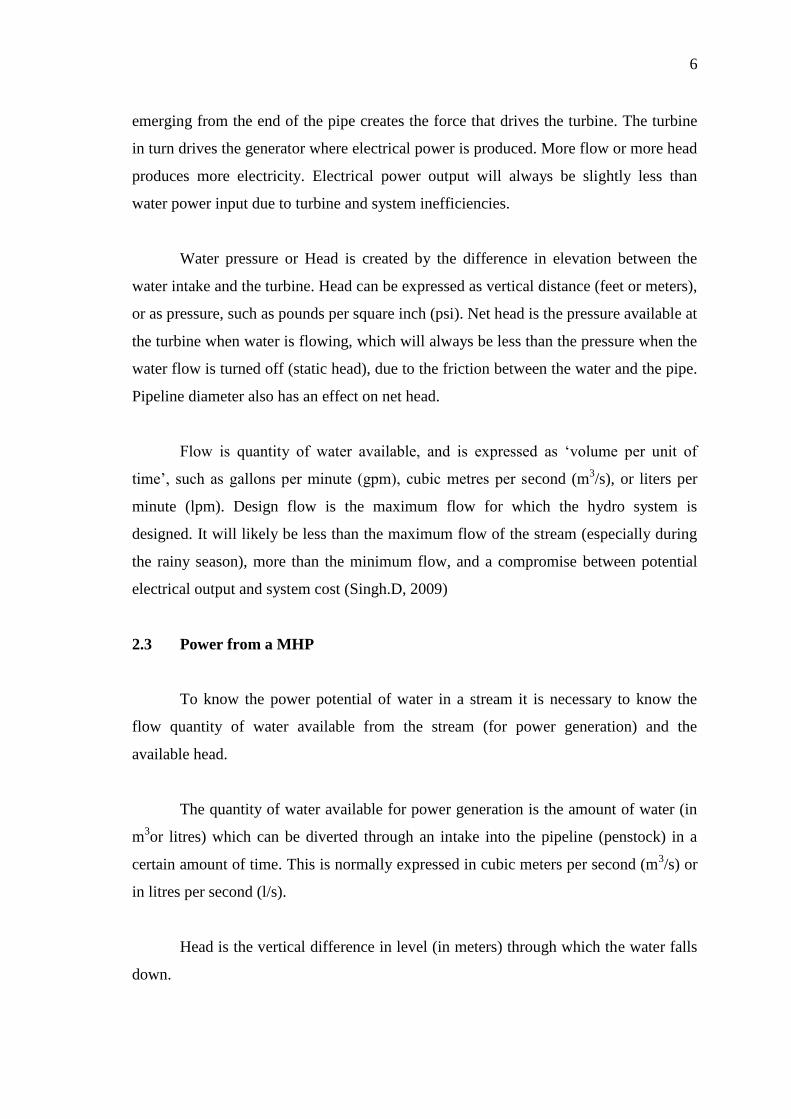
1. Pelton turbine
Pelton wheel used the concept of jet force to create energy. Water is funnelled
into a pressurized pipeline with a narrow nozzle at one end. The water spray out of the
nozzle in a jet, striking the double-cupped buckets attached to the wheel. The impact of
the jet spray on the curved buckets creates a force that rotates the wheel at high
efficiency rate of 70-90%. Pelton wheel turbines are available in various sizes and
operate best under low-flow and high-head condition.
10
Figure 2.2: Pelton Turbine
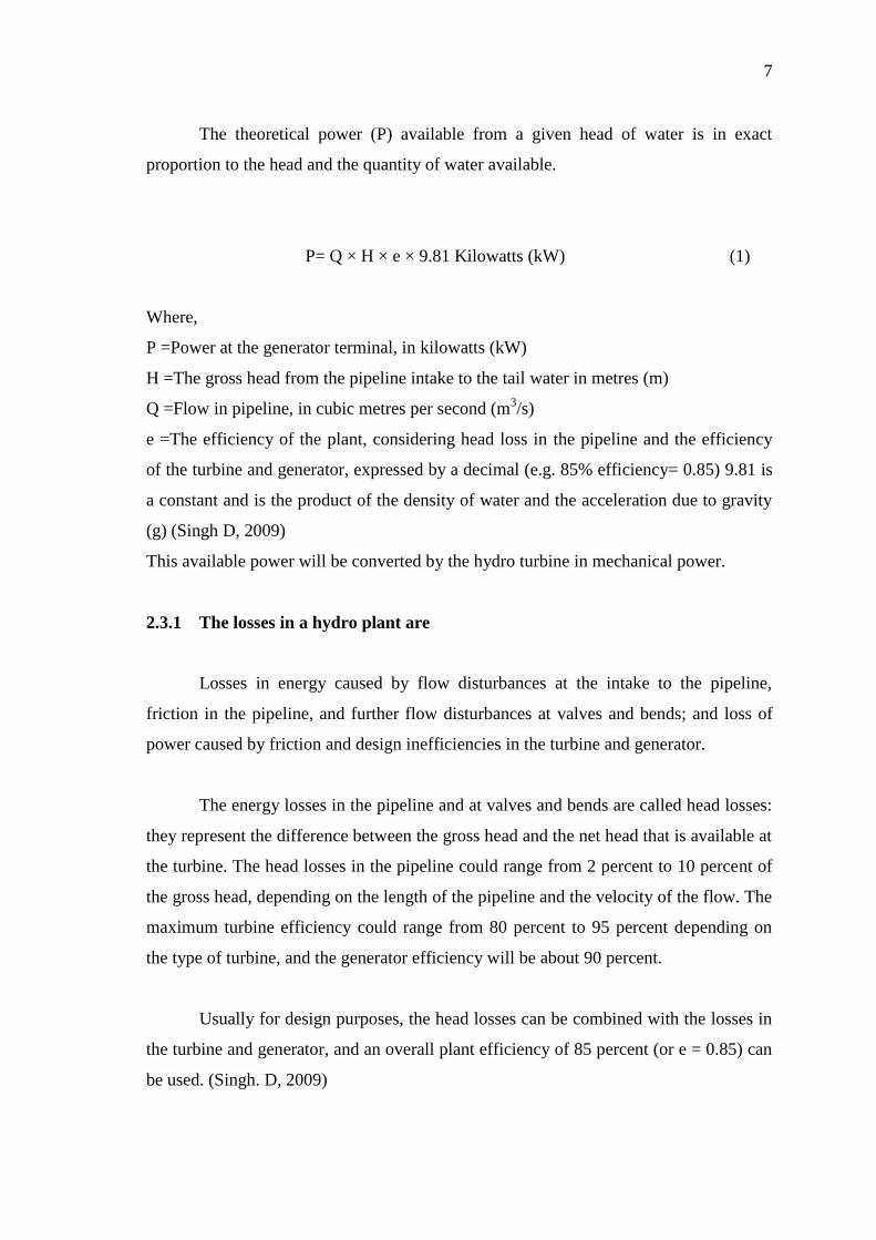
2. Turgo turbine
Turgo impulse wheels an upgraded version of the Pelton. It uses the same jet
spray concept, but the Turgo jet, which is half the size of the Pelton, is angled so that
the spray hits three buckets at once. As a result, the Turgo wheel moves twice as fast.
It’s also less bulky, needs few or no gears, and has a good reputation for trouble-free
operations. The Turgo can operate under low-flow conditions but requires a medium or
high head.
Figure 2.3: Turgo Turbine

11
3. Cross flow turbine
Cross flow turbine is widely considered by many to be the most efficient and apt
type of turbine for application in micro hydro projects. Also called a Michell-Banki
turbine a cross flow turbine has a drum-shaped runner consisting of two parallel discs
connected together near their rims by a series of curved blades. A cross flow turbine
always has its runner shaft horizontal (unlike Pelton and Turgo turbines which can have
either horizontal or vertical shaft orientation).
Unlike most water turbines, which have axial or radial flows, in a cross flow
turbine the water passes through the turbine transversely, or across the turbine blades.
As with a waterwheel, water enters at the turbine's edge. After passing the runner, it
leaves on the opposite side. Going through the runner twice provides additional
efficiency. When the water leaves the runner, it also helps clean the runner of small
debris and pollution. The cross-flow turbines generally operate at low speeds.
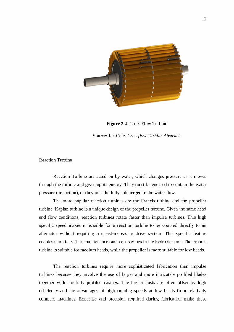
The turbine consists of a cylindrical water wheel or runner with a horizontal
shaft, composed of numerous blades (up to 37), arranged radially and tangentially. The
edges of the blades are sharpened to reduce resistance to the flow of water. A blade is
made in a part-circular cross-section (pipe cutover its whole length). The ends of the
blades are welded to disks to form a cage like a hamster cage and are sometimes called
"squirrel cage turbines"; instead of the bars, the turbine has trough-shaped steel blades.
12
Figure 2.4: Cross Flow Turbine
Source: Joe Cole. Crossflow Turbine Abstract.
Reaction Turbine
Reaction Turbine are acted on by water, which changes pressure as it moves
through the turbine and gives up its energy. They must be encased to contain the water
pressure (or suction), or they must be fully submerged in the water flow.
The more popular reaction turbines are the Francis turbine and the propeller
turbine. Kaplan turbine is a unique design of the propeller turbine. Given the same head
and flow conditions, reaction turbines rotate faster than impulse turbines. This high
specific speed makes it possible for a reaction turbine to be coupled directly to an
alternator without requiring a speed-increasing drive system. This specific feature
enables simplicity (less maintenance) and cost savings in the hydro scheme. The Francis
turbine is suitable for medium heads, while the propeller is more suitable for low heads.
The reaction turbines require more sophisticated fabrication than impulse
turbines because they involve the use of larger and more intricately profiled blades
together with carefully profiled casings. The higher costs are often offset by high
efficiency and the advantages of high running speeds at low heads from relatively
compact machines. Expertise and precision required during fabrication make these
13
turbines less attractive for use in micro-hydro in developing countries. Most reaction
turbines tend to have poor part-flow efficiency characteristics.
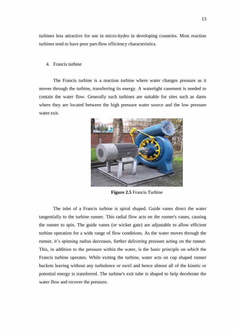
4. Francis turbine
The Francis turbine is a reaction turbine where water changes pressure as it
moves through the turbine, transferring its energy. A watertight casement is needed to
contain the water flow. Generally such turbines are suitable for sites such as dams
where they are located between the high pressure water source and the low pressure
water exit.
Figure 2.5 Francis Turbine
The inlet of a Francis turbine is spiral shaped. Guide vanes direct the water
tangentially to the turbine runner. This radial flow acts on the runner's vanes, causing
the runner to spin. The guide vanes (or wicket gate) are adjustable to allow efficient
turbine operation for a wide range of flow conditions. As the water moves through the
runner, it’s spinning radius decreases, further delivering pressure acting on the runner.
This, in addition to the pressure within the water, is the basic principle on which the
Francis turbine operates. While exiting the turbine, water acts on cup shaped runner
buckets leaving without any turbulence or swirl and hence almost all of the kinetic or
potential energy is transferred. The turbine's exit tube is shaped to help decelerate the
water flow and recover the pressure.