SIK Guide
80
SIK GUIDE Your Guide to the SparkFun Inventor’s Kit for Arduino SIK GUIDE Your Guide to the SparkFun Inventor’s Kit for Arduino
-
Upload
radu-martin -
Category
Documents
-
view
213 -
download
0
description
The guide that comes with the SIK Arduino project.
Transcript of SIK Guide

SIK GUIDEYour Guide to the SparkFun Inventor’s Kit for Arduino
RESET
SIK GUIDEYour Guide to the SparkFun Inventor’s Kit for Arduino
RESET

The SparkFun Inventor's Guide is your map for navigating the waters of beginning embedded electronics. This booklet contains all the information you will need to explore the 14 circuits of the SparkFun Inventor's Kit for Arduino. At the center of this manual is one core philosophy - that anyone can (and should) play around with electronics. When you're done with this guide, you'll have the know-how to start creating your own projects and experiments. Now enough talking - let's get inventing!
sparkfun.com
Welcome to the SparkFun Inventor’s Guide
Table of Contents

What is an Arduino? 1
Download Arduino Software (IDE) 3
Install Drivers for Arduino 4
Identify your Arduino 7
Download “SIK Guide Code” 8
The World Runs on Circuits 9
Inventory of Parts 11
13
15
17
24
28
32
36
40
44
48
52
Section 2: Getting Started with Circuits
Section 1: Getting Started with Arduino
Arduino Uno
Breadboard
Circuit #1 - Your First Circuit: Blinking a LED
Circuit #3 - RGB LED
Circuit #4 - Multiple LEDs
Circuit #5 - Push Buttons
Circuit #6 - Photo Resistor
Circuit #7 - Temperature Sensor
Circuit #8 - A Single Servo
Circuit #9 - Flex Sensor
56Circuit #10 - Soft Potentiometer
60Circuit #11 - Piezo Element
64Circuit #12 - Spinning a Motor
68Circuit #13 - Relay
72Circuit #14 - Shift Register
Circuit #2 - Potentiometer

Arduino is an open-source physical computing platform designed to make experimenting with electronics more fun and intuitive. Arduino has its own unique, simplified programming language, a vast support network, and thousands of potential uses, making it the perfect platform for both beginner and advanced DIY enthusiasts.
arduino.cc
The Arduino Revolution
What is an Arduino?
The friendly blue board in your hand (or on your desk) is the Arduino. In some ways you could think of Arduino as the child of traditional desktop and laptop computers. At its roots, the Arduino is essentially a small portable computer. It is capable of taking inputs (such as the push of a button or a reading from a light sensor) and interpreting that information to control various outputs (like a blinking LED light or an electric motor).
That's where the term "physical computing" is born - an Arduino is capable of taking the world of electronics and relating it to the physical world in a real and tangible way. Trust us - this will all make more sense soon.
A Computer for the Physical World
// Arduino UNO SMD R3
The Arduino Uno is one of several development boards based on the ATmega328. We like it mainly because of its extensive support network and its versatility. It has 14 digital input/output pins (6 of which can be PWM outputs), 6 analog inputs, a 16 MHz crystal oscillator, a USB connection, a power jack, an ICSP header, and a reset button. Don’t worry, you’ll learn about all these later.

cb
a
d
e
f
g
h
c
b
a
f
e
d
h
g
Power-Lacing High Tops
Old Toy Email Notifer
Bug Zapper Counter
Re-Programmed Traffic Light
Auto-Plant Watering
Camera Time-lapse operation
Quadcopter
Auto-Coffee Maker

In order to get your Arduino up and running, you'll need to download some software first from www.arduino.cc (it's free!). This software, known as the Arduino IDE, will allow you to program the Arduino to do exactly what you want. It’s like a word processor for writing programs. With an internet-capable computer, open up your favorite browser and type in the following URL into the address bar:
Access the Internet
Download the Arduino IDE (Integrated Development Environment)
user
Windows
Mac OS X
Linux: 32 bit, 64 bit
N
W
S
E
NW
SW
SE
NE
arduino.cc/en/Main/Software < case sensitive >
Choose the appropriate Operating System installation package for your computer.
Download Click on the “ + ” sign next to your appropriate computer operating system.
WindowsMac OS X
sourceLinux: 32 bit, 64 bit
1

// Connect your Arduino Uno to your ComputerUse the USB cable provided in the SIK kit to connect the Arduino to one of your computer’s USB inputs.
// Install DriversDepending on your computer’s operating system, you will need to follow specific instructions. Please consult the URLs below for specific instructions on how to install the drivers onto your Arduino Uno.
* You will need to scroll to the section labeled “Install the drivers”.
23
Linux: 32 bit / 64 bit, Installation ProcessGo to the web address below to access the instructions for installations on a Linux-based computer.
http://www.arduino.cc/playground/Learning/Linux
Macintosh OS X Installation ProcessMacs do not require you to install drivers. Enter the following URL if you have questions. Otherwise proceed to next page. http://arduino.cc/en/Guide/MacOSX
Windows Installation ProcessGo to the web address below to access the instructions for installations on a Windows-based computer.
http://arduino.cc/en/Guide/Windows

1 2 3 5 6
7
8
9
4
Open the Arduino IDE software on your computer. Poke around and get to know the interface. We aren’t going to code right away, this is just an introduction. The step is to set your IDE to identify your Arduino Uno.
// Open the Arduino IDE:

// The three most important commands for this guide are seen below:
GUI (Graphical User Interface)
Verify: Compiles and approves your code. It will catch errors in syntax (like missing semi-colons or parenthesis). // See Diagram Below1
Upload: Sends your code to the Arduino board. When you click it, you should see the lights on your board blink rapidly. // See Diagram Below2
New: This buttons opens up a new code window tab.3
Open: This button will let you open up an existing sketch. // See Diagram Below4
Save: This saves the currently active sketch.5
Serial Monitor: This will open a window that displays any serial information your Arduino is transmitting. It is very useful for debugging.6
Code Area: This is the area where you compose the code for your sketch. 8
Message Area: This is where the IDE tells you if there were any errors in your code.9
Sketch Name: This shows the name of the sketch you are currently working on.7
Verify
Upload
Open

File Edit Sketch Tools Help
Auto FormatArchive SketchFix Encoding & ReloadSerial Monitor
Arduino UnoArduino Duemilanove w/ ATmega328]Arduino Diecimila or Duemilanove w/ ATmega168Arduino Nano w/ ATmega328Arduino Nano w/ ATmega168Arduino Mega 2560 or Mega ADKArduino Mega (ATmega1280)Arduino Mini Arduino Mini w/ATmega168Arduino EthernetArduino FioArduino BT w/ ATmega328Arduino BT w/ATmega168LilyPad Arduino w/ ATmega328LilyPad Arduino w/ ATmega168Arduino Pro or Pro Mini (5V, 16 MHz) w/ATmega328Arduino Pro or Pro Mini (5V, 16 MHz) w/ATmega168Arduino Pro or Pro Mini (3.3V, 8 MHz) w/ATmega328Arduino Pro or Pro Mini (3.3V, 8 MHz) w/ATmega168Arduino NG or older w/ ATmega168Arduino NG or older w/ ATmega8
ProgrammerBurn Bootloader
BoardSerial Port
// Select your board: Arduino Uno
Select the serial device of the Arduino board from the Tools | Serial Port menu. This is likely to be com3 or higher (COM1 and COM2 are usually reserved for hardware serial ports). To find out, you can disconnect your Arduino board and re-open the menu; the entry that disappears should be the Arduino board. Reconnect the board and select that serial port.
Select the serial device of the Arduino board from the Tools > Serial Port menu. On the Mac, this should be something with /dev/tty.usbmodem (for the Uno or Mega 2560) or /dev/tty.usbserial (for older boards) in it.
http://www.arduino.cc/playground/Learning/Linux
Tools Help
Auto FormatArchive SketchFix Encoding & ReloadSerial Monitor
com 1com 12
ProgrammerBurn Bootloader
BoardSerial Port
Tools Help
Auto FormatArchive SketchFix Encoding & ReloadSerial Monitor
/dev/tty.usbmodem262471 /dev/cu.usbmodem262471 /dev/tty.Bluetooth-Modem /dev/cu.Bluetooth-Modem /dev/tty.FireFly-7256-SPP /dev/cu.FireFly-7256-SPP /dev/tty.tiPhone-WirelessiAP-1 /dev/cu.tiPhone-WirelessiAP-1 /dev/tty.Bluetooth-PDA-Sync /dev/cu.Bluetooth-PDA-Sync
ProgrammerBurn Bootloader
BoardSerial Port
// S
elec
t you
r Ser
ial D
evic
e
4

Type in the following URL to download the code:
Download Arduino Code (For use with the circuits in this guide)
sparkfun.com/sikcode
5
Unzip the file “SIK Guide Code”. It should be located in your browser’s “Downloads” folder. Right click the zipped folder and choose “unzip”.
Copy the “SIK Guide Code” folder into Arduino’s folder named “examples”.
Copy the “SIK Guide Code” folder into Arduino’s folder named “examples”.
Unzip the file “SIK Guide Code”. It should be loacted in your browser’s “Downloads” folder. Right click the zipped folder and choose “unzip”.
Find “Arduino” in your applications folder. Right click(ctrl + click) on “Arduino”. Select “Show Package Contents”.
http://www.arduino.cc/playground/Learning/Linux
// C
opy
“SIK
Gui
de C
ode”
into
“Ex
ampl
es”
libra
ry in
Ard
uino
fold
er
ProgramsStart arduino examples
Contents
Resources
Java
examplesArduino
Move to Trash
Open
Show Package Contents

Everywhere you look, you'll find circuits. The cell phone in your pocket, the computer that controls your car's emissions system, your video game console - all these things are chock full of circuits. In this guide, you'll experiment with some simple circuits and learn the gist of the world of embedded electronics.
The World Runs on Circuits:
Getting Started with Circuits
A circuit is basically an electronics loop with a starting point and an ending point - with any number of compo-nents in between. Circuits can include resistors, diodes, inductors, sensors of all sizes and shapes, motors, and any other handful of hundreds of thousands of components.
Circuits are usually divided into three categories - analog circuits, digital circuits, or mixed-signal circuits. In this guide, you will explore all three sets of circuits.
What is an Electrical Circuit?
// Simple and Complex Circuits
In this guide, you will be primarily exploring simple circuits - but that doesn't mean you can't do amazing things with simple tools! When you've finished the SIK, your knowledge of circuits will enable you to explore amazing projects and unleash the power of you imagination.
a b c d e f g h i123456789101112131415161718192021222324252627282930
a b c d e f g h i
123456789101112131415161718192021222324252627282930


Inventory of Parts
* ACTUAL SIZE
(1N4148)Diode
x2
x1
Piezo Element
Various ColorsJumper Wire
x30
Push Button
x2x1
DC Motor
x1
DC Motor
x1
Potentiometer
(Light Emitting Diode)
x10 x10 x1
LED (5mm) +-
330Ω Resistor
x25 * ACTUAL SIZE
10KΩ Resistor
x25 * ACTUAL SIZE
(TMP36)
x1
Temp. Sensor
FRONT
BACK
(P2N2222AG)
x2
Transistor
P2N2
222A
A18
FRONT
BACK
x1
Photo Resistor

Standard Solderless Breadboard
a b c d e f g h i123456789101112131415161718192021222324252627282930
a b c d e f g h i
123456789101112131415161718192021222324252627282930
UNO - PTH VersionArduino Board
AREFGND
13121110
98
65
7
43210
3.3V5V
RESET
GNDGNDVIN DIG
ITAL (PWM
)
WWW.ARDUINO.CC
POW
ER
RESET
RESET-EN
RX TX L
A1 A2
A0
A3A4A5
MADE
IN ITA
LY
ANALO
G IN
TXRX
Standard Solderless Breadboard
a b c d e f g h i123456789101112131415161718192021222324252627282930
a b c d e f g h i
123456789101112131415161718192021222324252627282930
UNO - SMD VersionArduino BoardFlex Sensor
x1
Soft Potentiometer
x1
Servo
x1
Relay
x1
x1
x1
(IC)Integrated Circuit
x1

3
1
2
4 5
7
8
9
6
10
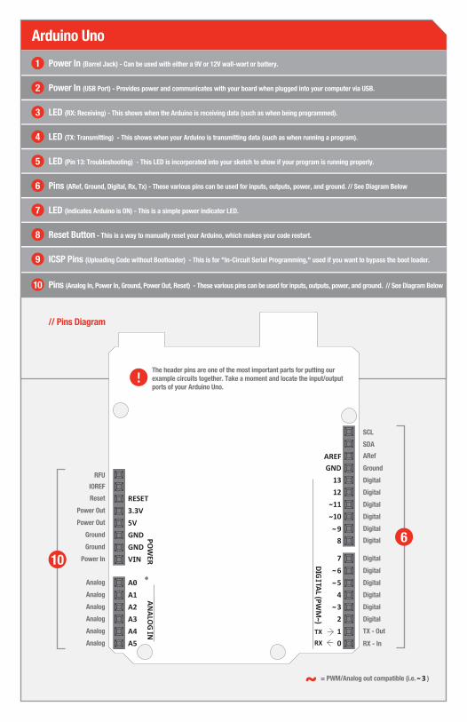
// Pins Diagram
Arduino Uno
Power In (Barrel Jack) - Can be used with either a 9V or 12V wall-wart or battery.1
Power In (USB Port) - Provides power and communicates with your board when plugged into your computer via USB.2
LED (RX: Receiving) - This shows when the Arduino is receiving data (such as when being programmed).3
LED (TX: Transmitting) - This shows when your Arduino is transmitting data (such as when running a program). 4
LED (Pin 13: Troubleshooting) - This LED is incorporated into your sketch to show if your program is running properly.5
Pins (ARef, Ground, Digital, Rx, Tx) - These various pins can be used for inputs, outputs, power, and ground. // See Diagram Below 6
LED (Indicates Arduino is ON) - This is a simple power indicator LED.7
Reset Button - This is a way to manually reset your Arduino, which makes your code restart.8
Pins (Analog In, Power In, Ground, Power Out, Reset) - These various pins can be used for inputs, outputs, power, and ground. // See Diagram Below10
ICSP Pins (Uploading Code without Bootloader) - This is for "In-Circuit Serial Programming," used if you want to bypass the boot loader.9
Power Out
Reset
IOREF
RFU
Power Out
Ground
Ground
Power In
Analog
Analog
Analog
Analog
Analog
Analog
Ground
ARef
SDA
SCL
Digital
Digital
Digital
Digital
Digital
Digital
Digital
Digital
Digital
Digital
Digital
Digital
TX - Out
RX - In
10
6
= PWM/Analog out compatible (i.e. )
The header pins are one of the most important parts for putting our example circuits together. Take a moment and locate the input/output ports of your Arduino Uno.
a b c d e f g h i123456789101112131415161718192021222324252627282930
a b c d e f g h i
123456789101112131415161718192021222324252627282930
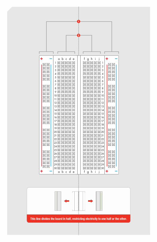
This line divides the board in half, restricting electricity to one half or the other.
1
2

Power:Each + sign runs power anywhere in the vertical column.
Ground:Each - sign runs to ground anywhere in the vertical column.
Horizontal Rows:Each of these rows numbered 1-30 are comprised of five horizontal sockets. Components placed in the same row will be connected in a circuit when power is running.
Vertical Connection (+ Power and - Ground // See Diagram Below)1
Horizontal Connection (a-e & f-j // See Diagram Below)2
How’s it all connected?
View of the inside
f g h ia b c d e123456789101112131415161718192021222324252627282930
a b c d e f g h i
123456789101112131415161718192021222324252627282930
Breadboard
Above the breadboard
CONNECTED!
LED
Making a Connection:
Inside the breadboard
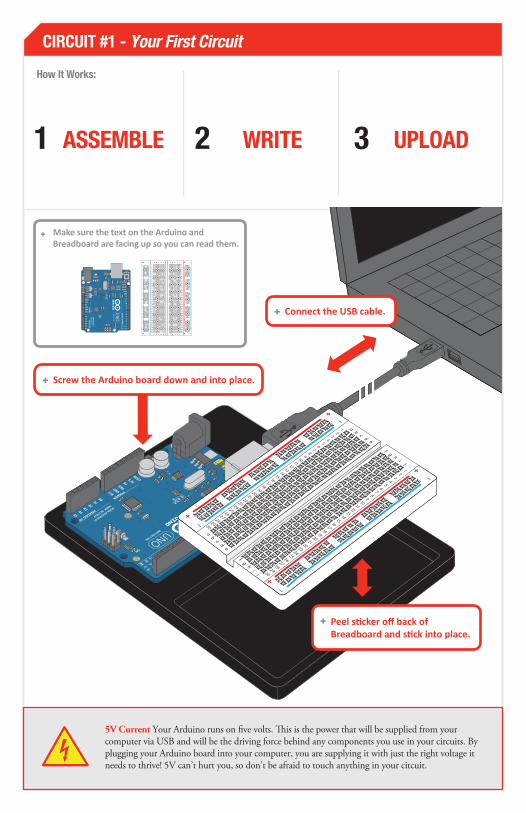
CIRCUIT #1 - Your First Circuit
5V Current Your Arduino runs on five volts. This is the power that will be supplied from your computer via USB and will be the driving force behind any components you use in your circuits. By plugging your Arduino board into your computer, you are supplying it with just the right voltage it needs to thrive! 5V can’t hurt you, so don’t be afraid to touch anything in your citcuit.
WĞĞůƐƟĐŬĞƌŽīďĂĐŬŽĨƌĞĂĚďŽĂƌĚĂŶĚƐƟĐŬŝŶƚŽƉůĂĐĞ
How It Works:
ASSEMBLE WRITE UPLOAD
DĂŬĞƐƵƌĞƚŚĞƚĞdžƚŽŶƚŚĞƌĚƵŝŶŽĂŶĚƌĞĂĚďŽĂƌĚĂƌĞĨĂĐŝŶŐƵƉƐŽLJŽƵĐĂŶƌĞĂĚƚŚĞŵ
a b c d e f g h i123456789101112131415161718192021222324252627282930
a b c d e f g h i
123456789101112131415161718192021222324252627282930
^ĐƌĞǁƚŚĞƌĚƵŝŶŽďŽĂƌĚĚŽǁŶĂŶĚŝŶƚŽƉůĂĐĞ
ŽŶŶĞĐƚƚŚĞh^ĐĂďůĞ

PART
S: LED
1X
Wire
3X
330ΩResistor
1X dŚŝƐƐĞĐƟŽŶůŝƐƚƐƚŚĞƉĂƌƚƐLJŽƵǁŝůůŶĞĞĚƚŽĐŽŵƉůĞƚĞƚŚĞĐŝƌĐƵŝƚ
Circuit 2
LEDs (light-emitting diodes) are small, powerful lights that are used in many different applications. To start off the SIK, we will work on blinking an LED. That's right - it's as simple as turning a light on and off. It might not seem like much, but establishing this important baseline will give you a solid foundation as we work toward more complex experiments.
Blinking a LED 1
ĂĐŚŝƌĐƵŝƚďĞŐŝŶƐǁŝƚŚĂďƌŝĞĨĚĞƐĐƌŝƉƟŽŶŽĨƚŚĞǁŚĂƚLJŽƵĂƌĞƉƵƫŶŐƚŽŐĞƚŚĞƌĂŶĚƚŚĞĞdžƉĞĐƚĞĚƌĞƐƵůƚ
dŚŝƐŝƐĂƐĐŚĞŵĂƟĐŽĨLJŽƵƌĐŝƌĐƵŝƚ
Arduino
LED(Light Emitting Diode)
GND(ground) (-)
Resistor(Orange-Orange-Brown)
(330ohm)
dŚŝƐŝƐĂŶŝůůƵƐƚƌĂƟŽŶŽĨŚŽǁƚŚĞĐŽŵƉůĞƚĞĚĐŝƌĐƵŝƚƐŚŽƵůĚůŽŽŬ/ƚŝƐŶŽƚŶĞĐĞƐƐĂƌLJƚŽƵƐĞƚŚĞďůĂĐŬŚŽůĚĞƌĨŽƌƚŚĞƌĚƵŝŶŽĂŶĚƌĞĂĚďŽĂƌĚďƵƚǁĞƌĞĐŽŵŵĞŶĚŝƚĨŽƌƚŚĞĮƌƐƚƟŵĞŝŶǀĞŶƚŽƌ
ŽŵƉŽŶĞŶƚƐůŝŬĞZĞƐŝƐƚŽƌƐŶĞĞĚƚŽŚĂǀĞƚŚĞŝƌůĞŐƐďĞŶƚŝŶƚŽϵϬ° ĂŶŐůĞƐŝŶŽƌĚĞƌƚŽĐŽƌƌĞĐƚůLJĮƚƚŚĞďƌĞĂĚďŽĂƌĚƐŽĐŬĞƚƐ
Pin 13
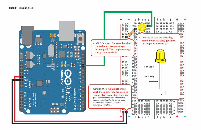
Circuit 1: Blinking a LED
a b c d e f g h i123456789101112131415161718192021222324252627282930
a b c d e f g h i
123456789101112131415161718192021222324252627282930
LED: DĂŬĞƐƵƌĞƚŚĞƐŚŽƌƚůĞŐŵĂƌŬĞĚǁŝƚŚŇĂƚƐŝĚĞŐŽĞƐŝŶƚŽƚŚĞŶĞŐĂƟǀĞƉŽƐŝƟŽŶ(-). ϯϯϬɏZĞƐŝƐƚŽƌdŚĞĐŽůŽƌďĂŶĚŝŶŐ
ƐŚŽƵůĚƌĞĂĚŽƌĂŶŐĞͲŽƌĂŶŐĞ-ďƌŽǁŶͲŐŽůĚdŚĞĐŽŵƉŽŶĞŶƚůĞŐƐĐĂŶŐŽŝŶĞŝƚŚĞƌŚŽůĞ
:ƵŵƉĞƌtŝƌĞ AůůũƵŵƉĞƌǁŝƌĞƐǁŽƌŬƚŚĞƐĂŵĞdŚĞLJĂƌĞƵƐĞĚƚŽĐŽŶŶĞĐƚƚǁŽƉŽŝŶƚƐƚŽŐĞƚŚĞƌ dŚŝƐŐƵŝĚĞǁŝůůƐŚŽǁƚŚĞǁŝƌĞƐǁŝƚŚĚŝīĞƌĞŶƚĐŽůŽƌĞĚŝŶƐƵůĂƟŽŶƐĨŽƌĐůĂƌŝƚLJďƵƚƵƐŝŶŐĚŝīĞƌĞŶƚĐŽŵďŝŶĂƟŽŶƐŽĨĐŽůŽƌƐŝƐĐŽŵƉůĞƚĞůLJĂĐĐĞƉƚĂďůĞ
Flat Edge
Short Leg

Component: Image Reference:
LED (5mm)+ -
+- c2 c3
Jumper Wire WŝŶϭϯ e2
330Ω Resistor a3GNDa3
Jumper Wire GND
Jumper Wire 5V5V + ϱsŽŶƚŚĞƌĚƵŝŶŽĐŽŶŶĞĐƚƐƚŽƚŚĞƌŽǁŵĂƌŬĞĚнŽŶƚŚĞƌĞĂĚďŽĂƌĚ
“WŝŶϭϯ” ŽŶƚŚĞƌĚƵŝŶŽĐŽŶŶĞĐƚƐƚŽƐŽĐŬĞƚe2ŽŶƚŚĞƌĞĂĚďŽĂƌĚ
'EŽŶƚŚĞƌĚƵŝŶŽƐŚŽƵůĚďĞĐŽŶŶĞĐƚĞĚƚŽƚŚĞƌŽǁŵĂƌŬĞĚͲŽŶƚŚĞƌĞĂĚďŽĂƌĚ
ŽŵƉŽŶĞŶƚƐůŝŬĞ>ƐĂƌĞŝŶƐĞƌƚĞĚŝŶƚŽƚŚĞƌĞĂĚďŽĂƌĚƐŽĐŬĞƚƐĐϮ;ůŽŶŐůĞŐͿĐϯ;ƐŚŽƌƚůĞŐͿ
ZĞƐŝƐƚŽƌƐĂƌĞƉůĂĐĞĚŝŶƌĞĂĚďŽĂƌĚƐŽĐŬĞƚƐŽŶůLJ dŚĞͲƐLJŵďŽůƌĞƉƌĞƐĞŶƚƐĂŶLJƐŽĐŬĞƚŝŶŝƚƐǀĞƌƟĐĂůĐŽůƵŵŶ
ƌĞĂĚďŽĂƌĚdŚĞǁŚŝƚĞďĂĐŬŐƌŽƵŶĚƌĞƉƌĞƐĞŶƚƐĂĐŽŶŶĞĐƟŽŶƚŽĂďƌĞĂĚďŽĂƌĚƐŽĐŬĞƚ
ƌĚƵŝŶŽdŚĞďůƵĞďĂĐŬŐƌŽƵŶĚƌĞƉƌĞƐĞŶƚƐĂĐŽŶŶĞĐƟŽŶƚŽŽŶĞŽĨƚŚĞƌĚƵŝŶŽŚĞĂĚĞƌƉŝŶƐ
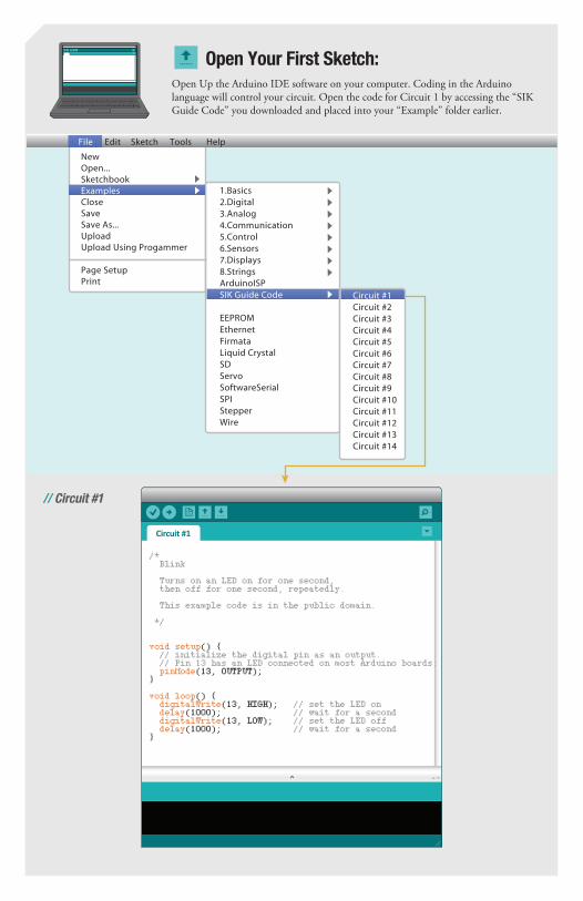
Open Up the Arduino IDE software on your computer. Coding in the Arduino language will control your circuit. Open the code for Circuit 1 by accessing the “SIK Guide Code” you downloaded and placed into your “Example” folder earlier.
Open Your First Sketch:
File Edit Sketch Tools Help
1.Basics2.Digital3.Analog4.Communication5.Control6.Sensors7.Displays8.StringsArduinoISPSIK Guide Code
EEPROMEthernetFirmataLiquid CrystalSDServoSoftwareSerialSPIStepperWire
Page SetupPrint
NewOpen...SketchbookExamplesCloseSaveSave As...UploadUpload Using Progammer
Circuit #1Circuit #2Circuit #3Circuit #4Circuit #5Circuit #6Circuit #7Circuit #8Circuit #9Circuit #10Circuit #11Circuit #12Circuit #13Circuit #14
ŝƌĐƵŝƚηϭ
/* Blink
Turns on an LED on for one second, then off for one second, repeatedly. This example code is in the public domain.
*/
void setup() // initialize the digital pin as an output. // Pin 13 has an LED connected on most Arduino boards: pinMode(13, OUTPUT);
void loop() digitalWrite(13, HIGH); // set the LED on delay(1000); // wait for a second digitalWrite(13, LOW); // set the LED off delay(1000); // wait for a second
// Circuit #1

sĞƌŝĨLJ
hƉůŽĂĚ
// The result of a completed circuit with correct code after verified and uploaded.
This compiles your code. The IDE changes it from text into instructions the computer can understand.
This sends the instructions via the USB cable to the computer chip on the Arduino board. The Arduino will then begin running your code automatically.
Circuit 2 Arduino Code:1
Troubleshooting:
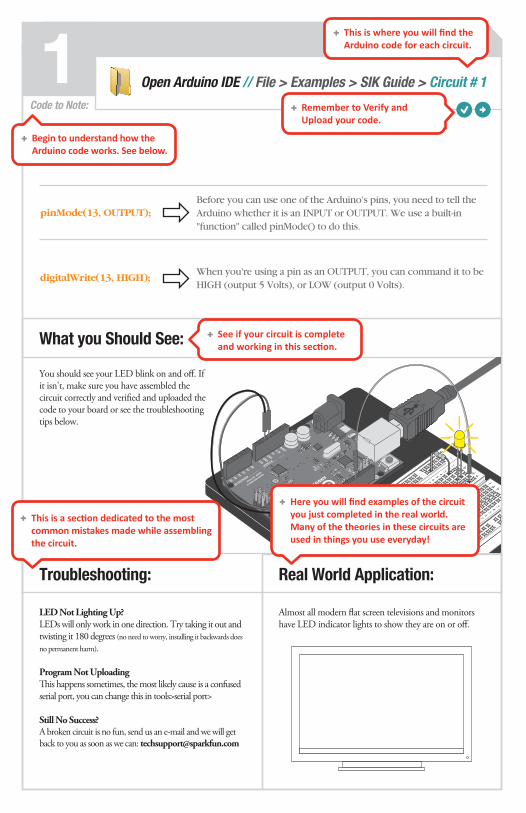
LED Not Lighting Up?LEDs will only work in one direction. Try taking it out and twisting it 180 degrees (no need to worry, installing it backwards does no permanent harm).
Program Not Uploading This happens sometimes, the most likely cause is a confused serial port, you can change this in tools>serial port>
Still No Success?A broken circuit is no fun, send us an e-mail and we will get back to you as soon as we can: [email protected]
You should see your LED blink on and off. If it isn't, make sure you have assembled the circuit correctly and verified and uploaded the code to your board or see the troubleshooting tips below.
Before you can use one of the Arduino's pins, you need to tell the Arduino whether it is an INPUT or OUTPUT. We use a built-in "function" called pinMode() to do this.
When you're using a pin as an OUTPUT, you can command it to be HIGH (output 5 Volts), or LOW (output 0 Volts).
digitalWrite(13, HIGH);
pinMode(13, OUTPUT);
Code to Note:
Real World Application:
Almost all modern flat screen televisions and monitors have LED indicator lights to show they are on or off.
Open Arduino IDE // File > Examples > SIK Guide > Circuit # 1
What you Should See:
dŚŝƐŝƐǁŚĞƌĞLJŽƵǁŝůůĮŶĚƚŚĞƌĚƵŝŶŽĐŽĚĞĨŽƌĞĂĐŚĐŝƌĐƵŝƚ
ZĞŵĞŵďĞƌƚŽsĞƌŝĨLJĂŶĚhƉůŽĂĚLJŽƵƌĐŽĚĞ
^ĞĞŝĨLJŽƵƌĐŝƌĐƵŝƚŝƐĐŽŵƉůĞƚĞĂŶĚǁŽƌŬŝŶŐŝŶƚŚŝƐƐĞĐƟŽŶ
ĞŐŝŶƚŽƵŶĚĞƌƐƚĂŶĚŚŽǁƚŚĞƌĚƵŝŶŽĐŽĚĞǁŽƌŬƐ^ĞĞďĞůŽǁ
dŚŝƐŝƐĂƐĞĐƟŽŶĚĞĚŝĐĂƚĞĚƚŽƚŚĞŵŽƐƚĐŽŵŵŽŶŵŝƐƚĂŬĞƐŵĂĚĞǁŚŝůĞĂƐƐĞŵďůŝŶŐƚŚĞĐŝƌĐƵŝƚ
,ĞƌĞLJŽƵǁŝůůĮŶĚĞdžĂŵƉůĞƐŽĨƚŚĞĐŝƌĐƵŝƚLJŽƵũƵƐƚĐŽŵƉůĞƚĞĚŝŶƚŚĞƌĞĂůǁŽƌůĚDĂŶLJŽĨƚŚĞƚŚĞŽƌŝĞƐŝŶƚŚĞƐĞĐŝƌĐƵŝƚƐĂƌĞƵƐĞĚŝŶƚŚŝŶŐƐLJŽƵƵƐĞĞǀĞƌLJĚĂLJ

Pin 13
Pin AØ
Circuit 2PA
RTS: Wire
19X
CIRCUIT #5
IC
1X
330ΩResistor
8X
LED
8X
Circuit 2
In this circuit you’ll work with a potentiometer. A potentiometer is also known as a variable resistor. When it’s connected with 5 volts across its two outer pins, the middle pin outputs a voltage between 0 and 5, depending on the position of the knob on the potentiometer. In this circuit, you’ll learn how to use a potentiometer to control the brightness of an LED.
Potentiometer
PART
S: Wire
6X
CIRCUIT #2 2
LED
1X
330ΩResistor
1X
Arduino PotentiometerArduino
+5 Volts
LED
resistor(Orange-Orange-Brown)
GND(ground) (-)
(330ohm)
Potentiometer
1X
p.10p.24

Circuit 2: Potentiometer
a b c d e f g h i123456789101112131415161718192021222324252627282930
a b c d e f g h i
123456789101112131415161718192021222324252627282930

Component: Image Reference:
Potentiometer
e6Jumper Wire
e8Jumper Wire
Jumper Wire GND
Jumper Wire 5VWŝŶϭϯ j20
Jumper Wire GND
Jumper Wire 5V5V +
+-
+ -h20 h21LED (5mm)
330Ω Resistor i21 +
Jumper Wire A0 e7
+
a6
a7
a8If you look closely at your Arduino, you'll see some pins labeled "DIGITAL", and some labeled "ANALOG". What's the difference?
Many of the devices you'll interface to, such as LEDs and pushbuttons, have only two possible states: on and off, or as they're known to the Arduino, "HIGH" (5 Volts) and "LOW" (0 Volts). The digital pins on an Arduino are great at getting these signals to and from the outside world, and can even do tricks like simulated dimming (by blinking on and off really fast), and serial communications (transferring data to another device by encoding it as patterns of HIGH and LOW).
But there are also a lot of things out there that aren't just "on" or "off". Temperature levels, control knobs, etc. all have a continuous range of values between HIGH and LOW. For these situations, the Arduino offers six analog inputs that translate an input voltage into a number that ranges from 0 (0 Volts) to 1023 (5 Volts). The analog pins are perfect for measuring all those "real world" values, and allow you to interface the Arduino to all kinds of things.
Digital versus Analog:
DIGITAL
0 volts
0
5 volts
1023ANALOG
HIGH
on
5 volts
LOW
off
0 volts

MP3 players’ volume control is an example of a potentiometer in action.
Circuit 2 Arduino Code:2
Troubleshooting:
Sporadically Working This is most likely due to a slightly dodgy connection with the potentiometer's pins. This can usually be conquered by holding the potentiometer down.
Not WorkingMake sure you haven't accidentally connected the potentiometer's wiper to digital pin 2 rather than analog pin 2. (the row of pins beneath the power pins).
Still BackwardYou can try operating the circuit upside down. Sometimes this helps.
You should see the LED blink faster or slower in accordance with your potentiometer. If it isn't working, make sure you have assembled the circuit correctly and verified and uploaded the code to your board or see the troubleshooting tips below.
A "variable" is a number you've given a name to. You must introduce, or "declare" variables before you use them; here we're declaring a variable called sensorValue, of type "int" (integer). Don't forget that variable names are case-sensitive!
int sensorValue;
Code to Note:
Real World Application:
Open Arduino IDE // File > Examples > SIK Guide > Circuit # 2
What you Should See:
The Arduino is very very fast, capable of running thousands of lines of code each second. To slow it down so that we can see what it's doing, we'll often insert delays into the code. Delay() counts in milliseconds; there are 1000 ms in one second.
delay(sensorValue);
We use the analogRead() function to read the value on an
analog pin. analogRead() takes one parameter, the analog
pin you want to use ("sensorPin"), and returns a number
("sensorValue") between 0 (0 Volts) and 1023 (5 Volts).
sensorValue = analogRead(sensorPin);
Circuit 2PA
RTS:
p.10
IC
1X
330ΩResistor
8X
LED
8X
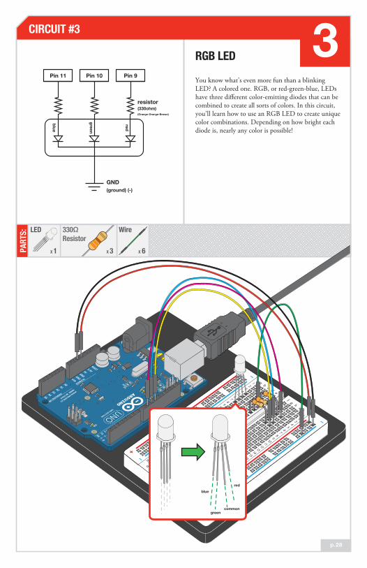
You know what’s even more fun than a blinking LED? A colored one. RGB, or red-green-blue, LEDs have three different color-emitting diodes that can be combined to create all sorts of colors. In this circuit, you’ll learn how to use an RGB LED to create unique color combinations. Depending on how bright each diode is, nearly any color is possible!
RGB LED
PART
S:CIRCUIT #3 3
p.28
Potentiometer
1X
TransistorP2N2222AG
1X
Pin 11 Pin 10 Pin 9
red
green
blue
resistor(330ohm)(Orange-Orange-Brown)
GND(ground) (-)
Wire
6X
330ΩResistor
3X
LED
1X
red
commongreen
blue

Circ
uit 3
: RGB
LED
ab
cd
ef
gh
i1 2 3 4 5 6 7 8 9 10 11 12 13 14 15 16 17 18 19 20 21 22 23 24 25 26 27 28 29 30
ab
cd
ef
gh
i
1 2 3 4 5 6 7 8 9 10 11 12 13 14 15 16 17 18 19 20 21 22 23 24 25 26 27 28 29 30
* Th
e lo
nges
t le
ad is
the
com
mon
(gnd
).

Component: Image Reference:
e7 e115V330Ω Resistor g4e4
e7 e115V330Ω Resistor g6e6
e7 e115V330Ω Resistor g7e7
RGB LED (5mm)
Jumper Wire GND
Jumper Wire 5V5V +
Jumper Wire WŝŶϵ h4
Jumper Wire WŝŶϭϬ h6
Jumper Wire WŝŶϭϭ h7
e5Jumper Wire
We've seen that the Arduino can read analog voltages (voltages between 0 and 5 Volts) using the analogRead() function. Is there a way for the Arduino to output analog voltages as well?
The answer is no... and yes. The Arduino does not have a true analog voltage output. But, because the Arduino is so fast, it can fake it using something called PWM ("Pulse-Width Modulation").
The Arduino is so fast that it can blink a pin on and off almost 1000 times per second. PWM goes one step further by varying the amount of time that the blinking pin spends HIGH vs. the time it spends LOW. If it spends most of its time HIGH, a LED connected to that pin will appear bright. If it spends most of its time LOW, the LED will look dim. Because the pin is blinking much faster than your eye can detect, the Arduino creates the illusion of a "true" analog output.
The shocking truth behind analogWrite():
90%
90%
50%
50%
0.5 v
2.5 v
4.5 v
LOW (0 volts)
HIGH (5 volts)
LOW (0 volts)
HIGH (5 volts)
LOW (0 volts)
HIGH (5 volts)
10%
10%
a4 a5 a6 a7

Many electronics such as videogame consoles use RGB LEDs to have the versatility to show different colors in the same area. Often times the diffent colors represent different states of working condition.
Circuit 2 Arduino Code:3
Troubleshooting:
LED Remains Dark or Shows Incorrect ColorWith the four pins of the LED so close together, it’s sometimes easy to misplace one. Double check each pin is where it should be.
Seeing RedThe red diode within the RGB LED may be a bit brighter than the other two. To make your colors more balanced, use a higher ohm resistor. Or adjust in code.
analogWrite(RED_PIN, redIntensity); to analogWrite(RED_PIN, redIntensity/3);
You should see your LED turn on, but this time in new, crazy colors! If it isn't, make sure you have assembled the circuit correctly and verified and uploaded the code to your board or see the troubleshooting tips below.
Code to Note:
Real World Application:
Open Arduino IDE // File > Examples > SIK Guide > Circuit # 3
What you Should See:
A for() loop is used to step a number across a range, and repeatedly runs code within the brackets . Here the variable "x" starts a 0, ends at 767, and increases by one each time ("x++").
for (x = 0; x < 768; x++)
The Arduino is very very fast, capable of running thousands of lines of code each second. To slow it down so that we can see what it's doing, we'll often insert delays into the code. Delay() counts in milliseconds; there are 1000 ms in one second.
delay(sensorValue);
"If / else" statements are used to make choices in your programs. The
statement within the parenthesis () is evaluated; if it's true, the code within
the first brackets will run. If it's not true, the code within the second
brackets will run.
if (x <= 255)else
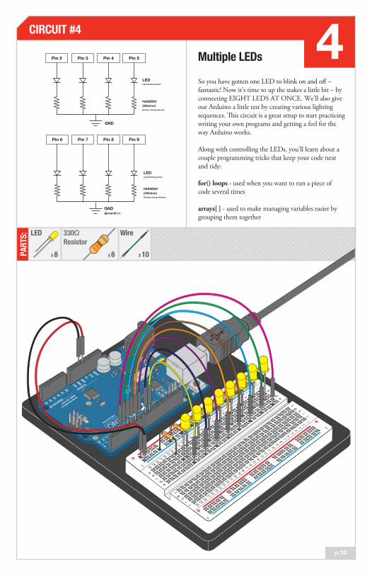
So you have gotten one LED to blink on and off – fantastic! Now it's time to up the stakes a little bit – by connecting EIGHT LEDS AT ONCE. We'll also give our Arduino a little test by creating various lighting sequences. This circuit is a great setup to start practicing writing your own programs and getting a feel for the way Arduino works.
Along with controlling the LEDs, you’ll learn about a couple programming tricks that keep your code neat and tidy:
for() loops - used when you want to run a piece of code several times
arrays[ ] - used to make managing variables easier by grouping them together
Multiple LEDsPin 2 Pin 3 Pin 4 Pin 5
GND
LEDLight Emitting Diode
LEDLight Emitting Diode
resistor(330ohm)(Orange-Orange-Brown)
resistor(330ohm)(Orange-Orange-Brown)
Pin 6 Pin 7 Pin 8 Pin 9
GND(ground) (-)
p.32
PART
S: LED
8X
Wire
10X
330ΩResistor
8X
CIRCUIT #4 4Pin 2 Pin 3 Pin 4 Pin 5
Pin 6 Pin 7 Pin 8 Pin 9

Circuit 4: Multiple LEDs
a b c d e f g h i123456789101112131415161718192021222324252627282930
a b c d e f g h i
123456789101112131415161718192021222324252627282930

Component: Image Reference:Component: Image Reference:
330Ω Resistor a18GND
330Ω Resistor
330Ω Resistor
Jumper Wire
Jumper Wire
Jumper Wire
Jumper Wire
Jumper Wire
Jumper Wire
Jumper Wire
Jumper Wire
Jumper Wire 5V
Jumper Wire
LED (5mm)+ -
+- c2 c3
e2WŝŶϮ
330Ω Resistor a15GND
330Ω Resistor a12GND
330Ω Resistor a9GND
330Ω Resistor a6GND
330Ω Resistor a3GNDc23 c24
LED (5mm) +-
+ -c23 c24
LED (5mm) +-
+ -c20 c21
LED (5mm) +-
+ -c17 c18
LED (5mm) +-
+ -c14 c15
LED (5mm) +-
+ -c11 c12
LED (5mm) +-
+ -c8 c9
LED (5mm) +-
+ -c5 c6
a3GND
a24GND
a21GND
WŝŶϯ
WŝŶϯ
e5
GND -
WŝŶϰ e8
WŝŶϱ e11
WŝŶϲ e14
WŝŶϳ e17
WŝŶϴ e20
WŝŶϵ e23
+

Circuit 2 Arduino Code:4
Troubleshooting:
Some LEDs Fail to Light It is easy to insert an LED backwards. Check the LEDs that aren't working and ensure they the right way around.
Operating out of sequenceWith eight wires it's easy to cross a couple. Double check that the first LED is plugged into pin 2 and each pin there after.
Starting AfreshIts easy to accidentally misplace a wire without noticing. Pulling everything out and starting with a fresh slate is often easier than trying to track down the problem.
This is similar to circuit number one, but instead of one LED, you should see all the LEDs blink. If they aren't, make sure you have assembled the circuit correctly and verified and uploaded the code to your board or see the troubleshooting tips below.
Code to Note:
Real World Application:
Scrolling marquee displays are generally used to spread short segments of important information. They are built out of many LEDs.
Open Arduino IDE // File > Examples > SIK Guide > Circuit # 4
What you Should See:
When you have to manage a lot of variables, an "array" is a handy way to group them together. Here we're creating an array of integers, called ledPins, with eight elements.
int ledPins[] = 2,3,4,5,6,7,8,9;
Computers like to do the same things each time they run. But sometimes you want to do things randomly, such as simulating the roll of a dice. The random() function is a great way to do this. See http://arduino.cc/en/Reference/Random for more information.
index = random(8);
You refer to the elements in an array by their position. The first
element is at position 0, the second is at position 1, etc. You refer to
an element using "ledPins[x]" where x is the position. Here we're
making digital pin 2 HIGH, since the array element at position 0 is "2".
digitalWrite(ledPins[0], HIGH);
Circuit 2PA
RTS: Wire
19X
IC
1X
330ΩResistor
8X
LED
8X
Circuit 2
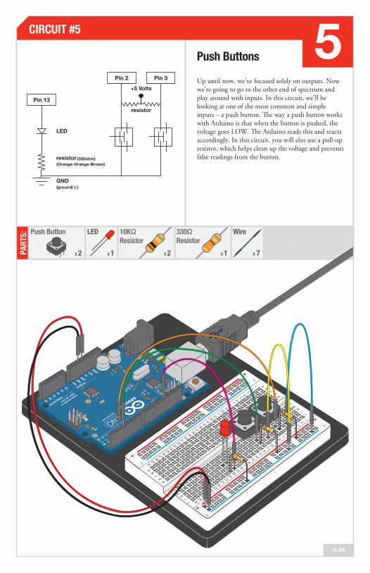
Up until now, we’ve focused solely on outputs. Now we’re going to go to the other end of spectrum and play around with inputs. In this circuit, we’ll be looking at one of the most common and simple inputs – a push button. The way a push button works with Arduino is that when the button is pushed, the voltage goes LOW. The Arduino reads this and reacts accordingly. In this circuit, you will also use a pull-up resistor, which helps clean up the voltage and prevents false readings from the button.
Push Buttons
PART
S: Wire
7X
CIRCUIT #5 5Pin 2
+5 Volts
resistor
Pin 3
LED
GND(ground) (-)
resistor(Orange-Orange-Brown)
(330ohm)
Push Button
2X
LED
1X
330ΩResistor
1X
10KΩResistor
2X
Pin 13
Pin 2 Pin 3
p.10p.36

Circuit 5: Push Buttons
a b c d e f g h i123456789101112131415161718192021222324252627282930
a b c d e f g h i
123456789101112131415161718192021222324252627282930

Component: Image Reference:
LED (5mm) +-
+ -h20 h21
Push Buttond4 g4
d6 g6
Push Buttond9 g9
d11 g11
Jumper Wire WŝŶϮ h6
Jumper Wire WŝŶϯ h11
Jumper Wire WŝŶϭϯ j20
i4Jumper Wire
i9Jumper Wire
10KΩ Resistor a15i6 +
10KΩ Resistor i11 +
330Ω Resistor j21 +
One of the things that makes the Arduino so useful is that it can make complex decisions based on the input it's getting. For example, you could make a thermostat that turns on a heater if it gets too cold, a fan if it gets too hot, waters your plants if they get too dry, etc.
In order to make such decisions, the Arduino provides a set of logic operations that let you build complex "if" statements. They include:
You can combine these functions to build complex if() statements.
For example:
if ((mode == heat) && ((temperature < threshold) || (override == true)))digitalWrite(HEATER, HIGH);
...will turn on a heater if you're in heating mode AND the temperature is low, OR if you turn on a manual override. Using these logic operators, you can program your Arduino to make intelligent decisions and take control of the world around it!
How to use logic like a Vulcan:
== EQUIVALENCE A == B is true if A and B are the SAME.
!= DIFFERENCE A != B is true if A and B are NOT THE SAME.
&& AND A && B is true if BOTH A and B are TRUE.
| | OR A || B is true if A or B or BOTH are TRUE.
! NOT !A is TRUE if A is FALSE, and FALSE if A is TRUE.

The buttons we used here are similar to the buttons in most videogame controllers.
Circuit 2 Arduino Code:5
Troubleshooting:
Light Not Turning On The pushbutton is square, and because of this it is easy to put it in the wrong way. Give it a 90 degree twist and see if it starts working.
Light Not Fading A bit of a silly mistake we constantly made, when you switch from simple on off to fading, remember to move the LED wire from pin 13 to pin 9.
Underwhelmed No worries, these circuits are all super stripped down to make playing with the components easy, but once you throw them together the sky is the limit.
You should see the LED turn on and off as you press the button. If it isn't working, make sure you have assembled the circuit correctly and verified and uploaded the code to your board or see the troubleshooting tips below.
Code to Note:
Real World Application:
Open Arduino IDE // File > Examples > SIK Guide > Circuit # 5
What You Should See:
The digital pins can be used as inputs as well as outputs. Before you do either, you need to tell the Arduino which direction you're going.
pinMode(button2Pin, INPUT);
Because we've connected the button to GND, it will read LOW when it's being pressed. Here we're using the "equivalence" operator ("==") to see if the button is being pressed.
if (button1State == LOW)
To read a digital input, you use the digitalRead() function. It will return HIGH if there's 5V present at the pin, or LOW if there's 0V present at the pin.
button1State = digitalRead(button1Pin);

Circuit 2
So you’ve already played with a potentiometer, which varies resistance based on the twisting of a knob. In this circuit, you’ll be using a photo resistor, which changes resistance based on how much light the sensor receives. Since the Arduino can’t directly interpret resistance (rather it reads voltage), we use a voltage divider to use our photo resistor. This voltage divider will output a high voltage when it is getting a lot of light and a low voltage when it is not.
Photo Resistor
PART
S: Wire
6X
CIRCUIT #6 6
LED
1X
330ΩResistor
1X
Photo Resistor
1X
LED
GND(ground) (-)
photoresistor
+5 Volts
resistor(Orange-Orange-Brown)
(330ohm)
resistor(Brown-Black-Orange)
(10k ohm)
10KΩResistor
1X
Pin 9
Pin AØ
p.40

Circuit 6 : Photo Resistor
a b c d e f g h i123456789101112131415161718192021222324252627282930
a b c d e f g h i
123456789101112131415161718192021222324252627282930

Component: Image Reference:
Photo Resistor
j1Jumper Wire
j6Jumper Wire
Jumper Wire GND
Jumper Wire 5V5V +
+-
+ -h20 h21LED (5mm)
330Ω Resistor (sensor) i21 +
10KΩ Resistor i1 i5
Jumper Wire A0 j5
+
f5 f6
Jumper Wire WŝŶϵ j20
Many of the sensors you'll use (potentiometers, photoresistors, etc.) are resistors in disguise. Their resistance changes in proportion to whatever they're sensing (light level, etc.).
The Arduino's analog input pins measure voltage, not resistance. But we can easily use resistive sensors with the Arduino by including them as part of a "voltage divider".
A voltage divider consists of two resistors. The "top" resistor is the sensor you'll be using. The "bottom" one is a normal, fixed resistor. When you connect the top resistor to 5 Volts, and the bottom resistor to ground, the middle will output a voltage proportional to the values of the two resistors. When one of the resistors changes (as it will when your sensor senses things), the output voltage will change as well!
Although the sensor's resistance will vary, the resistive sensors (flex sensor,light sensor, softpot, and trimpot) in the SIK are around 10K Ohms. We usually want the fixed resistor to be close to this value, so using a 10K resistor is a great choice for the fixed "bottom" resistor.
Measuring resistive sensors:
Pin 3
5 volts
GND(ground) (-)
Pin 3

A street lamp uses a light sensor to detect when to turn the lights on at night.
Circuit 2 Arduino Code:6
Troubleshooting:
LED Remains DarkThis is a mistake we continue to make time and time again, if only they could make an LED that worked both ways. Pull it up and give it a twist.
It Isn't Responding to Changes in LightGiven that the spacing of the wires on the photo-resistor is not standard, it is easy to misplace it. Double check it’s in the right place.
Still Not Quite WorkingYou may be in a room which is either too bright or dark. Try turning the lights on or off to see if this helps. Or if you have a flashlight near by give that a try.
You should see the LED grow brighter or dimmer in accordance with how much light your photoresistor is reading. If it isn't working, make sure you have assembled the circuit correctly and verified and uploaded the code to your board or see the troubleshooting tips below.
Code to Note:
Real World Application:
Open Arduino IDE // File > Examples > SIK Guide > Circuit # 6
What You Should See:
When we read an analog signal using analogRead(), it will
be a number from 0 to 1023. But when we want to drive a
PWM pin using analogWrite(), it wants a number from 0 to
255. We can "squeeze" the larger range into the smaller
range using the map() function.
lightLevel = map(lightLevel, 0, 1023, 0, 255);
Because map() could still return numbers outside the "to"
range, we'll also use a function called constrain() that will
"clip" numbers into a range. If the number is outside the
range, it will make it the largest or smallest number. If it is
within the range, it will stay the same.
lightLevel = constrain(lightLevel, 0, 255);

Circuit 2
A temperature sensor is exactly what it sounds like – a sensor used to measure ambient temperature. This particular sensor has three pins – a positive, a ground, and a signal. For every centigrade degree it reads, it outputs 10 millivolts. In this circuit, you’ll learn how to integrate the temperature sensor with your Arduino, and use the Arduino IDE’s debug window to display the temperature.
Temperature Sensor
CIRCUIT #7 7
p.44
Pin AØ
TMP36(precision
temperaturesensor)
GND(ground) (-)
5 Volts
+5vsignalgnd
PART
S: Wire
5X
Temp. Sensor
1
When you’re building the circuit be careful not to mix up the temperature sensor and the transistor, they’re almost identical.
X
FRONT
BACK

Circuit 7: Temperature Sensor
a b c d e f g h i123456789101112131415161718192021222324252627282930
a b c d e f g h i
123456789101112131415161718192021222324252627282930
Temperature Sensor f5 f7f6
Component: Image Reference:
j5Jumper Wire
j7Jumper Wire
Jumper Wire GND
Jumper Wire 5V5V +
Jumper Wire A0 j6
+
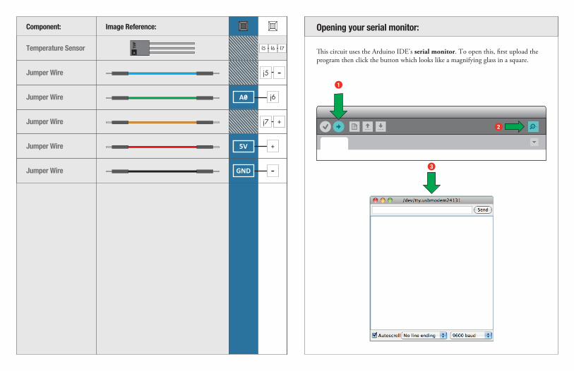
This circuit uses the Arduino IDE's serial monitor. To open this, first upload the program then click the button which looks like a magnifying glass in a square.
Opening your serial monitor:
1
2
3

Building climate control systems use a temperature sensor to monitor and maintain their settings.
Circuit 2 Arduino Code:7
Troubleshooting:
Nothing Seems to HappenThis program has no outward indication it is working. To see the results you must open the Arduino IDE's serial monitor (instructions on previous page).
Gibberish is DisplayedThis happens because the serial monitor is receiving data at a different speed than expected. To fix this, click the pull-down box that reads "*** baud" and change it to "9600 baud".
Temperature Value is Unchanging Try pinching the sensor with your fingers to heat it up or pressing a bag of ice against it to cool it down.
You should see be able to read the temperature your temperature sensor is detecting on the serial monitor in the Arduino IDE. If it isn't working, make sure you have assembled the circuit correctly and verified and uploaded the code to your board or see the troubleshoot-ing tips below.
Code to Note:
Real World Application:
Open Arduino IDE // File > Examples > SIK Guide > Circuit # 7
What You Should See:
voltage: 0.73 deg C: 22.75 deg F: 72.96
voltage: 0.73 deg C: 22.75 deg F: 72.96
voltage: 0.73 deg C: 22.75 deg F: 72.96
voltage: 0.73 deg C: 22.75 deg F: 72.96
voltage: 0.73 deg C: 22.75 deg F: 72.96
Before using the serial monitor, you must call Serial.begin() to initialize it. 9600 is the "baud rate", or communications speed. When two devices are communicating with each other, both must be set to the same speed.
Serial.begin(9600);
Serial.print() will print everything on the same line. Serial.println() will move to the next line. By using both of these commands together, you can create easy-to-read printouts of text and data.
Serial.println(degreesF);
The Serial.print() command is very smart. It can print out almost anything you can throw at it, including variables of all types, quoted text (AKA "strings"), etc.
See http://arduino.cc/en/Serial/Print for more info.
Serial.print(degreesC);
Circuit 2
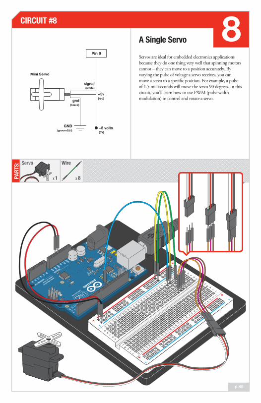
Servos are ideal for embedded electronics applications because they do one thing very well that spinning motors cannot – they can move to a position accurately. By varying the pulse of voltage a servo receives, you can move a servo to a specific position. For example, a pulse of 1.5 milliseconds will move the servo 90 degrees. In this circuit, you’ll learn how to use PWM (pulse width modulation) to control and rotate a servo.
A Single Servo
PART
S: Wire
8X
CIRCUIT #8 8
p.48
Servo
1X
Mini Servo
+5 volts(5V)
GND(ground) (-)
gnd(black)
signal(white)
+5v(red)
Pin 9
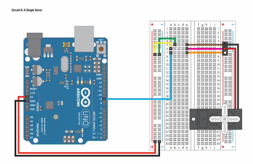
Circuit 8: A Single Servo
a b c d e f g h i123456789101112131415161718192021222324252627282930
a b c d e f g h i
123456789101112131415161718192021222324252627282930

Component: Image Reference:
Servo e5 e7e6
Jumper Wire
Jumper Wire
Jumper Wire
e6
e7
e5
5V
Jumper Wire WŝŶϵ a7
Jumper Wire
Jumper Wire
Jumper Wire
Jumper Wire GND
b5
+
a6 +
Arduino gives you a very useful set of built-in commands for doing basic input and output, making decisions using logic, solving math problems, etc. But the real power of Arduino is the huge community using it, and their willingness to share their work.
Libraries are collections of new commands that have been packaged together to make it easy to include them in your sketches. Arduino comes with a handful of useful libraries, such as the servo library used in this example, that can be used to interface to more advanced devices (LCD displays, stepper motors, ethernet ports, etc.)
See http: //arduino.cc/en/Reference/Libraries for a list of the standard libraries and information on using them.
But anyone can create a library, and if you want to use a new sensor or output device, chances are that someone out there has already written one that interfaces that device to the Arduino. Many of SparkFun's products come with Arduino libraries, and you can find even more using Google and the Arduino Playground at http://arduino.cc/playground/. And when YOU get the Arduino working with a new device, consider making a library for it and sharing it with the world!
To use a library in a sketch, select it from Sketch > Import Library.
Expand your horizons using Libraries:
File Edit Sketch Tools Help
EEPROMEthernetFirmataLiquidCrystalSDServoSoftwareSerialSPIStepperWire
Verify / Compile
Show Sketch FolderAdd File...Import Library

Circuit 2 Arduino Code:8
Troubleshooting:
Servo Not Twisting Even with colored wires it is still shockingly easy to plug a servo in backward. This might be the case.
Still Not WorkingA mistake we made a time or two was simply forgetting to connect the power (red and brown wires) to +5 volts and ground.
Fits and StartsIf the servo begins moving then twitches, and there's a flashing light on your Arduino board, the power supply you are using is not quite up to the challenge. Using a wall adapter instead of USB should solve this problem.
You should see your servo motor move to various locations at several speeds. If the motor doesn't move, check your connections and make sure you have verified and uploaded the code, or see the troubleshooting tips below.
Code to Note:
Real World Application:
Robotic arms you might see in an assembly line or sci-fi movie probably have servos in them.
Open Arduino IDE // File > Examples > SIK Guide > Circuit # 8
What You Should See:
#include is a special "preprocessor" command that inserts a library (or any other file) into your sketch. You can type this command yourself, or choose an installed library from the "sketch / import library" menu.
#include <Servo.h>
Servos don't spin all the way around, but they can be commanded to move to
a specific position. We use the servo library's write() command to move a
servo to a specified number of degrees(0 to 180). Remember that the servo
requires time to move, so give it a short delay() if necessary.
servo1.write(180);
The servo library adds new commands that let you control a servo. To prepare the Arduino to control a servo, you must first create a Servo "object" for each servo (here we've named it "servo1"), and then "attach" it to a digital pin (here we're using pin 9).
Servo servo1;
servo1.attach(9);
PART
S: IC
1X
330ΩResistor
8X
LED
8X
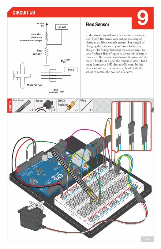
In this circuit, we will use a flex sensor to measure, well, flex! A flex sensor uses carbon on a strip of plastic to act like a variable resistor, but instead of changing the resistance by turning a knob, you change it by flexing (bending) the component. We use a "voltage divider" again to detect this change in resistance. The sensor bends in one direction and the more it bends, the higher the resistance gets; it has a range from about 10K ohm to 35K ohm. In this circuit we will use the amount of bend of the flex sensor to control the position of a servo.
Flex Sensor
PART
S:CIRCUIT #9 9
Potentiometer
1X
Servo
1X
Flex Sensor
1X
10KΩResistor
1X
Wire
11X
+5 volts(5V)
+5 volts(5V)
GND(ground) (-)
Mini Servo
resistor
flexsensor
(10K ohm)(Brown-Black-Orange)
p.10p.52
Pin AØ
Pin 9
a b c d e f g h i123456789101112131415161718192021222324252627282930
a b c d e f g h i
123456789101112131415161718192021222324252627282930
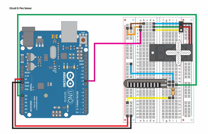
Circuit 9: Flex Sensor
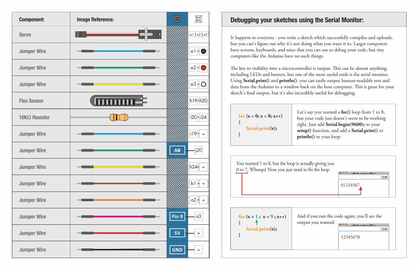
It happens to everyone - you write a sketch which successfully compiles and uploads, but you can't figure out why it's not doing what you want it to. Larger computers have screens, keyboards, and mice that you can use to debug your code, but tiny computers like the Arduino have no such things.
The key to visibility into a microcontroller is output. This can be almost anything, including LEDs and buzzers, but one of the most useful tools is the serial monitor. Using Serial.print() and println(), you can easily output human-readable text and data from the Arduino to a window back on the host computer. This is great for your sketch's final output, but it's also incredibly useful for debugging.
Debugging your sketches using the Serial Monitor:Component: Image Reference:
i20 i24
Servo e1 e3e2
e1Jumper Wire
i19Jumper Wire
h24 +Jumper Wire
h24 +Jumper Wire
h24 +Jumper Wire
Jumper Wire
Jumper Wire
Jumper Wire
Jumper Wire
e2Jumper Wire
e3Jumper Wire
Flex Sensor h19 h20
10KΩ Resistor
j20A0
b1 +
a2 +
a3WŝŶϵ
5V5V +
GND
And if you run the code again, you'll see the output you wanted:
for (x = 1 ; x < 9 ; x++) Serial.print(x); 12345678
You wanted 1 to 8, but the loop is actually giving you 0 to 7. Whoops! Now you just need to fix the loop.
01234567
Let's say you wanted a for() loop from 1 to 8, but your code just doesn't seem to be working right. Just add Serial.begin(9600); to your setup() function, and add a Serial.print() or println() to your loop:
for (x = 0; x < 8; x++) Serial.print(x);
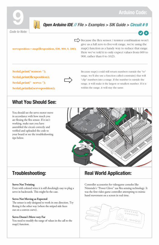
Controller accessories for videogame consoles like Nintendo’s “Power Glove” use flex-sensing technology. It was the first video game controller attempting to mimic hand movement on a screen in real time.
Circuit 2 Arduino Code:9
Troubleshooting:
Servo Not TwistingEven with colored wires it is still shockingly easy to plug a servo in backwards. This might be the case.
Servo Not Moving as ExpectedThe sensor is only designed to work in one direction. Try flexing it the other way (where the striped side faces out on a convex curve).
Servo Doesn’t Move very FarYou need to modify the range of values in the call to the map() function.
You should see the servo motor move in accordance with how much you are flexing the flex sensor. If it isn't working, make sure you have assembled the circuit correctly and verified and uploaded the code to your board or see the troubleshooting tips below.
Code to Note:
Real World Application:
Open Arduino IDE // File > Examples > SIK Guide > Circuit # 9
What You Should See:
Because the flex sensor / resistor combination won't give us a full zero to five-volt range, we're using the map() function as a handy way to reduce that range. Here we've told it to only expect values from 600 to 900, rather than 0 to 1023.
servoposition = map(flexposition, 600, 900, 0, 180);
Because map() could still return numbers outside the "to"
range, we'll also use a function called constrain() that will
"clip" numbers into a range. If the number is outside the
range, it will make it the largest or smallest number. If it is
within the range, it will stay the same.
Serial.print("sensor: ");
Serial.print(flexposition);
Serial.print(" servo: ");
Serial.println(servoposition);

Circuit 2PA
RTS:
CIRCUIT #5
p.10
IC
1X
330ΩResistor
8X
LED
8X
Circuit 2
In this circuit, we are going to use yet another kind of variable resistor – this time, a soft potentiometer (or soft pot). This is a thin and flexible strip that can detect where pressure is being applied. By pressing down on various parts of the strip, you can vary the resistance from 100 to 10K ohms. You can use this ability to track movement on the soft pot, or simply as a button. In this circuit, we’ll get the soft pot up and running to control an RGB LED.
Soft Potentiometer
PART
S:CIRCUIT #10 10
p.56
Wire
9X
330ΩResistor
3X
LED
1X
Soft Potentiometer
1X
330ΩResistor
3X
10KΩResistor
1X
Pin 0P
in 9
red
Pin
10
green
Pin
11
blue
+5 volts
V+
gnd
wiper
soft
pot
resistor(Orange-Orange-Brown)
(330ohm)
Brown-Black-Orange)resistor (10K ohm)
GND(ground) (-)
Pin AØP
in 9
Pin
10
Pin
11

a b c d e f g h i123456789101112131415161718192021222324252627282930
a b c d e f g h i
123456789101112131415161718192021222324252627282930
Circuit 10: Soft Potentiometer

Component: Image Reference: Component: Image Reference:
Jumper Wire GND
RGB LED (5mm) a4 a5 a6 a7
e7 e115V330Ω Resistor g4e4
e7 e115V330Ω Resistor g6e6
e7 e115V330Ω Resistor g7e7
Jumper Wire 5V5V +
Jumper Wire WŝŶϵ h4
Jumper Wire WŝŶϭϬ h6
Jumper Wire WŝŶϭϭ h7
e5Jumper Wire
j18Jumper Wire
j20Jumper Wire
Jumper Wire j19A0
+
5VSoft Potentiometer h19h18 h20
10KΩ Resistor i19

The knobs found on many objects, like a radio for instance, are using similar concepts to the one you just completed for this circuit.
Circuit 2 Arduino Code:10
Troubleshooting:
LED Remains Dark or Shows Incorrect ColorWith the four pins of the LED so close together, it’s sometimes easy to misplace one. Try double checking each pin is where it should be.
Bizarre ResultsThe most likely cause of this is if you’re pressing the potentiometer in more than one position. This is normal and can actually be used to create some neat results.
You should see the RGB LED change colors in accordance with how you interact with the soft potentiometer. If it isn't working, make sure you have assembled the circuit correctly and verified and uploaded the code to your board, or see the troubleshoot-ing tips below.
These big, scary functions take a single Value (RGBposition) and calculate the three RGB values necessary to create a rainbow of color. The functions create three "peaks" for the red, green, and blue values, which overlap to mix and create new colors. Even if you're not 100% clear how it works, you can copy and paste this (or any) function into your own code and use it yourself.
redValue = constrain(map(RGBposition, 0, 341, 255, 0), 0, 255) + constrain(map(RGBposition, 682, 1023, 0, 255), 0, 255);
greenValue = constrain(map(RGBposition, 0, 341, 0, 255), 0, 255) - constrain(map(RGBposition, 341, 682, 0,255), 0, 255);
blueValue = constrain(map(RGBposition, 341, 682, 0, 255), 0, 255)- constrain(map(RGBposition, 682, 1023, 0, 255), 0, 255);
Code to Note:
Real World Application:
Open Arduino IDE // File > Examples > SIK Guide > Circuit # 10
What You Should See:

Circuit 2
In this circuit, we'll again bridge the gap between the digital world and the analog world. We'll be using a buzzer that makes a small "click" when you apply voltage to it (try it!). By itself that isn't terribly exciting, but if you turn the voltage on and off hundreds of times a second, the buzzer will produce a tone. And if you string a bunch of tones together, you've got music! This circuit and sketch will play a classic tune. We'll never let you down!
Buzzer
PART
S: Wire
4X
CIRCUIT #11 11
p.60
Piezo Element
1X
Piezo Element
GND(ground) (-)
Pin 9
/ĨƚŚĞďƵnjnjĞƌĚŽĞƐŶΖƚĞĂƐŝůLJĮƚŝŶƚŽƚŚĞŚŽůĞƐŽŶƚŚĞďƌĞĂĚďŽĂƌĚƚƌLJƌŽƚĂƟŶŐŝƚƐůŝŐŚƚůLJ
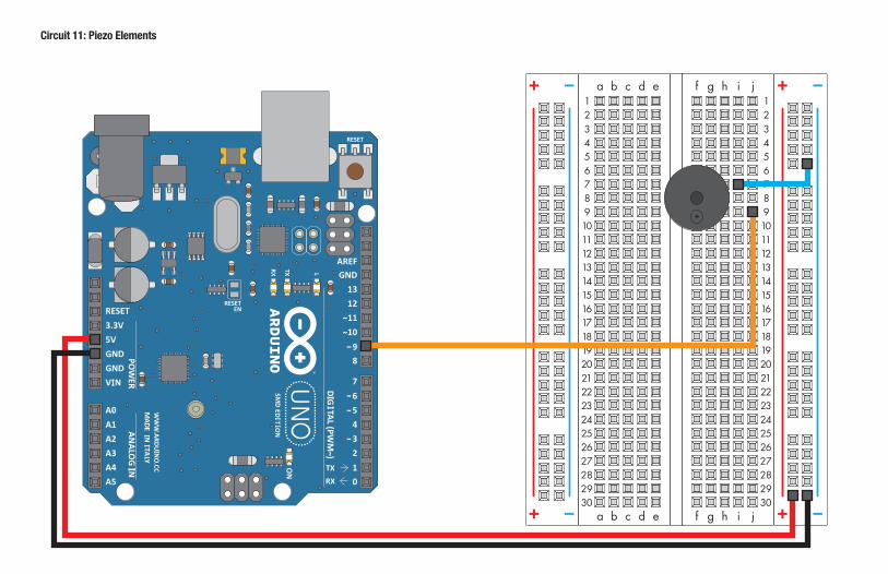
Circuit 11: Piezo Elements
a b c d e f g h i123456789101112131415161718192021222324252627282930
a b c d e f g h i
123456789101112131415161718192021222324252627282930

Component: Image Reference:
Piezo Element+ -j9 j7
Jumper Wire WŝŶϵ j9
i7
Jumper Wire GND
Jumper Wire
Jumper Wire 5V5V +
Arduino contains a wealth of built-in functions that are useful for all kinds of things. (See http://arduino.cc/en/Reference for a list). But you can also easily create your own functions. Here's a simple example named "add", which adds two numbers together and returns the result. Let's break it down.
Your functions can take in values ("parameters"), and return a value, as this one does. But you can also do either or none of those things, if you wish.
If you'll be passing parameters /to/ your function, put them (and their types) in the parentheses after the function name. If you won't be giving your function any parameters, just use an empty parenthesis () after the name.
If you'll be returning a value /from/ your function, put the type of the return value in front of the function name. Then in your function, when you're ready to return the value, put in a return() statement. If you won't be returning a value, put "void" in front of the function name (just like you've already seen for the setup() and loop() functions).
When you write your own functions, you make your code neater and easier to re-use.
Creating your own functions:
int add(int parameter1, int parameter2) int x;
x = parameter1 + parameter2;
return(x);
Many modern megaphones have settings that use a loud amplified buzzer. They are usually very loud and quite good at getting people’s attention.
Circuit 2 Arduino Code:11
Troubleshooting:
No SoundGiven the size and shape of the piezo element it is easy to miss the right holes on the breadboard. Try double checking its placement.
Can't Think While the Melody is PlayingJust pull up the piezo element whilst you think, upload your program then plug it back in.
Tired of Twinkle Twinkle Little StarThe code is written so you can easily add your own songs.
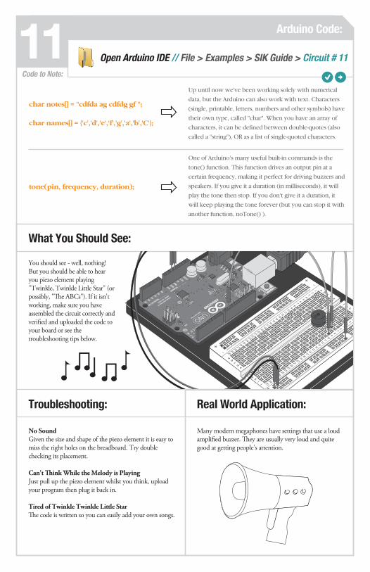
You should see - well, nothing! But you should be able to hear you piezo element playing "Twinkle, Twinkle Little Star" (or possibly, "The ABCs"). If it isn't working, make sure you have assembled the circuit correctly and verified and uploaded the code to your board or see the troubleshooting tips below.
Code to Note:
Real World Application:
Open Arduino IDE // File > Examples > SIK Guide > Circuit # 11
What You Should See:
Up until now we've been working solely with numerical
data, but the Arduino can also work with text. Characters
(single, printable, letters, numbers and other symbols) have
their own type, called "char". When you have an array of
characters, it can be defined between double-quotes (also
called a "string"), OR as a list of single-quoted characters.
char notes[] = "cdfda ag cdfdg gf ";
char names[] = 'c','d','e','f','g','a','b','C';
One of Arduino's many useful built-in commands is the
tone() function. This function drives an output pin at a
certain frequency, making it perfect for driving buzzers and
speakers. If you give it a duration (in milliseconds), it will
play the tone then stop. If you don't give it a duration, it
will keep playing the tone forever (but you can stop it with
another function, noTone() ).
tone(pin, frequency, duration);

Circuit 2
Remember before when you played around with a servo motor? Now we are going to tackle spinning a motor. This requires the use of a transistor, which can switch a larger amount of current than the Arduino can. When using a transistor, you just need to make sure its maximum specs are high enough for your use. The transistor we are using for this circuit is rated at 40V max and 200 milliamps max – perfect for our toy motor!
Spinning a Motor
PART
S: Wire
6X
CIRCUIT #12 12
1X
DC Motor
1X
Diode1N4148
p.64
TransistorP2N2222AG
1X
When you’re building the circuit be careful not to mix up the transistor and the temperature sensor, they’re almost identical.
330ΩResistor
1X
P2N2
222A
A18
P2N2
222A
A18
FRONT
BACK
GND(ground) (-)
basetransistor P2N2222AG
collector
mot
or
mul
timet
er
diode
emitter
+5 volts(5V)
resistor(Orange-Orange-Brown)
(330ohm)
Pin 9

Circ
uit 1
2 : S
pinn
ing
a M
otor
ab
cd
ef
gh
i1 2 3 4 5 6 7 8 9 10 11 12 13 14 15 16 17 18 19 20 21 22 23 24 25 26 27 28 29 30
ab
cd
ef
gh
i
1 2 3 4 5 6 7 8 9 10 11 12 13 14 15 16 17 18 19 20 21 22 23 24 25 26 27 28 29 30
Component: Image Reference:
Transistor P2N2222AG a1 a3a2
Jumper Wire
Jumper Wire WŝŶϵ j2
Jumper Wire
Jumper Wire
Jumper Wire 5V
Jumper Wire GND
Diode 1N4148 a3GNDb7 b11
e7 e11
e7 e11
DC Motor
5V330Ω Resistor g2e2
e1
a7 +
+
e3 d11
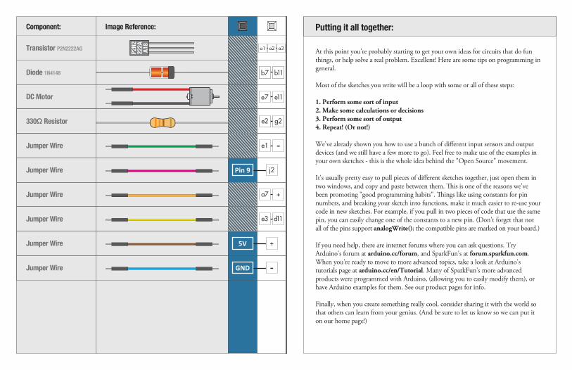
At this point you're probably starting to get your own ideas for circuits that do fun things, or help solve a real problem. Excellent! Here are some tips on programming in general.
Most of the sketches you write will be a loop with some or all of these steps:
1. Perform some sort of input2. Make some calculations or decisions3. Perform some sort of output4. Repeat! (Or not!)
We've already shown you how to use a bunch of different input sensors and output devices (and we still have a few more to go). Feel free to make use of the examples in your own sketches - this is the whole idea behind the "Open Source" movement.
It's usually pretty easy to pull pieces of different sketches together, just open them in two windows, and copy and paste between them. This is one of the reasons we've been promoting "good programming habits". Things like using constants for pin numbers, and breaking your sketch into functions, make it much easier to re-use your code in new sketches. For example, if you pull in two pieces of code that use the same pin, you can easily change one of the constants to a new pin. (Don't forget that not all of the pins support analogWrite(); the compatible pins are marked on your board.)
If you need help, there are internet forums where you can ask questions. Try Arduino's forum at arduino.cc/forum, and SparkFun's at forum.sparkfun.com. When you're ready to move to more advanced topics, take a look at Arduino's tutorials page at arduino.cc/en/Tutorial. Many of SparkFun's more advanced products were programmed with Arduino, (allowing you to easily modify them), or have Arduino examples for them. See our product pages for info.
Finally, when you create something really cool, consider sharing it with the world so that others can learn from your genius. (And be sure to let us know so we can put it on our home page!)
Putting it all together:
P2N2
222A
A18

Circuit 2 Arduino Code:12
Troubleshooting:
Motor Not SpinningIf you sourced your own transistor, double check with the data sheet that the pinout is compatible with a P2N2222AG (many are reversed).
Still No LuckIf you sourced your own motor, double check that it will work with 5 volts and that it does not draw too much power.
Still Not WorkingSometimes the Arduino board will disconnect from the computer. Try un-plugging and then re-plugging it into your USB port.
The DC Motor should spin if you have assembled the circuit’s components correctly, and also verified/uploaded the correct code. If your circuit is not working check the troubleshooting section below.
Code to Note:
Real World Application:
Radio Controlled(RC) cars use Direct Current(DC) motors to turn the wheels for propulsion.
Open Arduino IDE // File > Examples > SIK Guide > Circuit # 12
What You Should See:
The Arduino's serial port can be used to receive as well as
send data. Because data could arrive at any time, the Arduino
stores, or "buffers" data coming into the port until you're
ready to use it. The Serial.available() command returns the
number of characters that the port has received, but haven't
been used by your sketch yet. Zero means no data has arrived.
while (Serial.available() > 0)
If the port has data waiting for you, there are a number of
ways for you to use it. Since we're typing numbers into the
port, we can use the handy Serial.parseInt() command to
extract, or "parse" integer numbers from the characters it's
received. If you type "1" "0" "0" to the port, this function
will return the number 100.
speed = Serial.parseInt();

Circuit 2PA
RTS:
CIRCUIT #5 5
p.10
IC
1X
LED
8X
Circuit 2
In this circuit, we are going to use some of the lessons we learned in circuit 12 to control a relay. A relay is basically an electrically controlled mechanical switch. Inside that harmless looking plastic box is an electromagnet that, when it gets a jolt of energy, causes a switch to trip. In this circuit, you’ll learn how to control a relay like a pro – giving your Arduino even more powerful abilities!
Relays
PART
S:CIRCUIT #13 13
p.68
TransistorP2N2222AG
1X
Relay
1X 1X
Diode1N4148
Wire
14X
330ΩResistor
2X
LED
2X
GND(ground) (-)
basetransistor P2N2222AG
collector
diode(flyback)
coilNC
NO
com
emitter
5 volts
5 volts
resistor(Orange-Orange-Brown)
(330ohm)
resistor(Orange-Orange-Brown)
(330ohm)
LED LED When the relay is off, the COM (common) pin will be connected to the NC (Normally Closed) pin. When the relay is on, the COM (common) pin will be connected to the NO (Normally Open) pin.
Pin 2

Circuit 13: Relays
a b c d e f g h i123456789101112131415161718192021222324252627282930
a b c d e f g h i
123456789101112131415161718192021222324252627282930
Relaye9 f9
e15 f15
Component: Image Reference:
e2Jumper Wire
h9Jumper Wire +
f5 f7f6
Diode 1N4148 a3GNDb7 b11
Transistor P2N2222AG a2 a4a3
e7 e115V330Ω Resistor g3e3
e7 e115V330Ω Resistor g2e2
Component: Image Reference:
LED (5mm) +-
+ -c19 c20
LED (5mm) +-
+ -c22 c23
i13Jumper Wire i13 e22
j5Jumper Wire j7 j9
Jumper Wire i15 e19
Jumper Wire e15 e19
Jumper Wire e15 e19
Jumper Wire b14 e19
Jumper Wire a7 a9
Jumper Wire e4 e9
+ +
+
Jumper Wire e15 e19
Jumper Wire e15 e19
Jumper Wire a23
+
Jumper Wire GND
Jumper Wire 5V5V +
Jumper Wire WŝŶϮ j3
Jumper Wire a20
P2N2
222A
A18

Garage door openers use relays to operate. You might be able to hear the clicking if you listen closely.
Circuit 2 Arduino Code:13
Troubleshooting:
LEDs Not LightingDouble-check that you've plugged them in correctly. The longer lead (and non-flat edge of the plastic flange) is the positive lead.
No Clicking SoundThe transistor or coil portion of the circuit isn't quite working. Check the transistor is plugged in the right way.
Not Quite WorkingThe included relays are designed to be soldered rather than used in a breadboard. As such you may need to press it in to ensure it works (and it may pop out occasionally).
You should be able to hear the relay contacts click, and see the two LEDs alternate illuminating at 1-second intervals. If you don't, double-check that you have assembled the circuit correctly, and uploaded the correct sketch to the board. Also, see the troubleshooting tips below.
Code to Note:
Real World Application:
Open Arduino IDE // File > Examples > SIK Guide > Circuit # 13
What You Should See:
When we turn on the transistor, which in turn energizes
the relay's coil, the relay's switch contacts are closed. This
connects the relay's COM pin to the NO (Normally Open)
pin. Whatever you've connected using these pins will turn
on. (Here we're using LEDs, but this could be almost anything.)
digitalWrite(relayPin, HIGH);
The relay has an additional contact called NC (Normally
Closed). The NC pin is connected to the COM pin when
the relay is OFF. You can use either pin depending on
whether something should be normally on or normally off.
You can also use both pins to alternate power to two
devices, much like railroad crossing warning lights.
digitalWrite(relayPin, LOW);

Circuit 2
Shift Register
PART
S: Wire
19X
CIRCUIT #14 14
p.72
Now we are going to step into the world of ICs (integrated circuits). In this circuit, you’ll learn all about using a shift register (also called a serial-to-parallel controller). The shift register will give your Arduino an additional eight outputs, using only three pins on your board. For this circuit, you’ll practice by using the shift register to control eight LEDs.
IC
1X
330ΩResistor
8X
LED
8X
GND(ground) (-)
+5 volts
+5 volts
15 1016
1
2
3
4
5
6
78
11
12
14
13
data
clock
latch
resistors(Orange-Orange-Brown)
(330ohm) LEDs
4
Pin 3
Pin 4
Pin 2
Bend legs to 90° angle.
Align notch on top, inbetween “e5” and “f5” on
the breadboard.
1
2
3
4
5
6
7
8
QB
QC
QD
QE
QF
QG
QH
GND
VCC
QA
SER
OE
RCLK
SRCLK
SRCLR
QH’
16
15
14
13
12
11
10
9

Circuit 14: Shift Register
a b c d e f g h i123456789101112131415161718192021222324252627282930
a b c d e f g h i
123456789101112131415161718192021222324252627282930

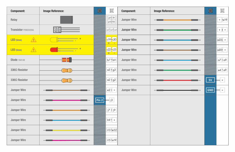
Component: Image Reference: Component: Image Reference:
LED (5mm) +- + -
c14 c15
LED (5mm) +- + -
c17 c18
LED (5mm) +- + -
c20 c21
LED (5mm) +- + -
c23 c24
LED (5mm) +- + -
h14 h15
LED (5mm) +- + -
h17 h18
LED (5mm) +- + -
h20 h21
LED (5mm) +- + -
h23 h24
a3a15330Ω Resistor
a3GNDc23 a18330Ω Resistor
a3GNDc23 a21330Ω Resistor
a3GNDc23 a24330Ω Resistor
a3GNDj15 c24330Ω Resistor
a3GNDj18 c24330Ω Resistor
a3GNDj21 c24330Ω Resistor
a3GNDj24 c24330Ω Resistor
IC e5
f5
e6
f6
e7
f7
e8
f8
e9
f9
e10
f10
e11
f11
e12
f12
a3GNDJumper Wire + +
a3GNDJumper Wire + +
a3GNDJumper Wire j5 +
a3GNDJumper Wire j6 a14
Jumper Wire
a3GNDJumper Wire j8 a14
Jumper Wire
Jumper Wire
a3GNDJumper Wire f14 a8
a3GNDJumper Wire f17 a9
a3GNDJumper Wire f20 a10
a3GNDJumper Wire f23 a11
a3GNDJumper Wire a23 a7
a3GNDJumper Wire a20 a6
a3GNDJumper Wire a17 a5
a3GNDJumper Wire a14 j6
Jumper Wire
Jumper Wire
j7WŝŶϮ
j9WŝŶϰ
j10WŝŶϯ
a3GNDJumper Wire j11 a14+
j105V +
GND
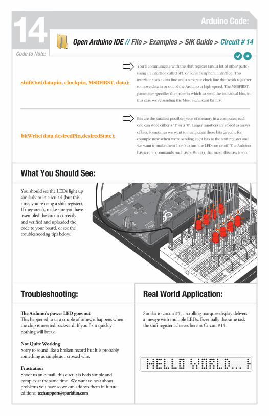
Similar to circuit #4, a scrolling marquee display delivers a mesage with multiple LEDs. Essentially the same task the shift register achieves here in Circuit #14.
Circuit 2 Arduino Code:14
Troubleshooting:
The Arduino's power LED goes out This happened to us a couple of times, it happens when the chip is inserted backward. If you fix it quickly nothing will break.
Not Quite WorkingSorry to sound like a broken record but it is probably something as simple as a crossed wire.
FrustrationShoot us an e-mail, this circuit is both simple and complex at the same time. We want to hear about problems you have so we can address them in future editions: [email protected]
You should see the LEDs light up similarly to in circuit 4 (but this time, you're using a shift register). If they aren't, make sure you have assembled the circuit correctly and verified and uploaded the code to your board, or see the troubleshooting tips below.
Code to Note:
Real World Application:
Open Arduino IDE // File > Examples > SIK Guide > Circuit # 14
What You Should See:
You'll communicate with the shift register (and a lot of other parts)
using an interface called SPI, or Serial Peripheral Interface. This
interface uses a data line and a separate clock line that work together
to move data in or out of the Arduino at high speed. The MSBFIRST
parameter specifies the order in which to send the individual bits, in
this case we're sending the Most Significant Bit first.
shiftOut(datapin, clockpin, MSBFIRST, data);
Bits are the smallest possible piece of memory in a computer; each
one can store either a "1" or a "0". Larger numbers are stored as arrays
of bits. Sometimes we want to manipulate these bits directly, for
example now when we're sending eight bits to the shift register and
we want to make them 1 or 0 to turn the LEDs on or off. The Arduino
has several commands, such as bitWrite(), that make this easy to do.
bitWrite(data,desiredPin,desiredState);

This is just the beginning of your exploration into embedded electronics and coding. Our website has a wealth of tutorials to whet your appetite for more knowledge. We also host a community of hackers, engineers, DIYers, etc. in our forums. So log on to our website for more information about Arduino, or to plan ahead for your next project!
sparkfun.com
Visit us Online:
Learning More
NOTES:

This work is licensed under the Creative Commons Attribution-Share Alike 3.0 Unported License.
To view a copy of this license visit: http://creativecommons.org/licenses/by-sa/3.0/
Or send a letter to:Creative Commons, 171 Second Street, Suite 300, San Francisco, California 94105, USA.