SHIPS FOR NAVIGATION IN ICE - Rules and standards · SHIPS FOR NAVIGATION IN ICE JULY 2007 ... G....
42
RULES FOR CLASSIFICATION OF DET NORSKE VERITAS Veritasveien 1, NO-1322 Høvik, Norway Tel.: +47 67 57 99 00 Fax: +47 67 57 99 11 SHIPS NEWBUILDINGS SPECIAL SERVICE AND TYPE ADDITIONAL CLASS PART 5 CHAPTER 1 SHIPS FOR NAVIGATION IN ICE JULY 2007 CONTENTS PAGE Sec. 1 General Requirements ................................................................................................................ 5 Sec. 2 Basic Ice Strengthening .............................................................................................................. 7 Sec. 3 Ice Strengthening for the Northern Baltic .................................................................................. 9 Sec. 4 Vessels for Arctic and Ice Breaking Service ........................................................................... 21 Sec. 5 Sealers ..................................................................................................................................... 37 Sec. 6 Winterization ............................................................................................................................ 38 Sec. 7 DAT(-X°C) ................................................................................................................................ 40
Transcript of SHIPS FOR NAVIGATION IN ICE - Rules and standards · SHIPS FOR NAVIGATION IN ICE JULY 2007 ... G....

RULES FORCLASSIFICATION OF
SHIPS
NEWBUILDINGS
SPECIAL SERVICE AND TYPEADDITIONAL CLASS
PART 5 CHAPTER 1
SHIPS FOR NAVIGATION IN ICEJULY 2007
CONTENTS PAGE
Sec. 1 General Requirements ................................................................................................................ 5Sec. 2 Basic Ice Strengthening.............................................................................................................. 7Sec. 3 Ice Strengthening for the Northern Baltic .................................................................................. 9Sec. 4 Vessels for Arctic and Ice Breaking Service ........................................................................... 21Sec. 5 Sealers ..................................................................................................................................... 37Sec. 6 Winterization ............................................................................................................................ 38Sec. 7 DAT(-X°C) ................................................................................................................................ 40
DET NORSKE VERITASVeritasveien 1, NO-1322 Høvik, Norway Tel.: +47 67 57 99 00 Fax: +47 67 57 99 11

CHANGES IN THE RULES
GeneralNew rules for Basic Ice Strengthening were introduced in the July2006 rules and came into force in January 2007. In the meantime, theusers have provided feedback that minor additions and clarificationsare needed. These have been incorporated as indicated below. The present edition of the rules supersedes the January 2007 editionof the same chapter.This chapter is valid until superseded by a revised chapter. Supple-ments will not be issued except for minor amendments and an updatedlist of corrections presented in Pt.0 Ch.1 Sec.3. Pt.0 Ch.1 is normallyrevised in January and July each year.Revised chapters will be forwarded to all subscribers to the rules.Buyers of reprints are advised to check the updated list of rule chap-ters printed in Pt.0 Ch.1 Sec.1 to ensure that the chapter is current.
Changes entering into force with immediate effect
• Sec.2 Basic Ice Strengthening— Item B101 has been replaced by:
The requirements for the forward ice belt region, as defined inSec.3 Fig.1, for sub-section elements 200 - 700, shall be in ac-cordance with Sec.3 as follows:— In Table B1, the value of ho and h shall be as given for ICE-
1C.— The ice pressure shall be determined in accordance with
Sec.3 B200, where the factor c1, as given in Table B3, is tak-en as being equal to 0.55.
— Vertical extension of the ice belt plating and framing shallbe:Plating: 0.5 m above UIWL and 0.5 m below LIWLFraming: 0.62 m above UIWL and 1.0 m below LIWL.
— Item B202, concerning ice plate shell plating, has been deleted.— In item B301, the bullet list has been replaced by:
a) Frames shall be effectively attached to all supporting struc-tures. Transverse and longitudinal frames crossing supportstructures shall be connected to these with lugs. Alternative-ly, top stiffener in combination with lug may be used. Theupper end of intermediate frames may be sniped at a stringeror deck provided the ice belt covers not more than 1/3 of thespan.
b) Frames where the angle between the web and the shell is lessthan 75 degrees shall be supported against tripping by brack-ets, intercostals, stringers or similar at a distance preferablynot exceeding 2.5 m.Transverse frames perpendicular to shell which are of un-symmetrical profiles shall have tripping preventions if thespan is exceeding 4.0 m.
c) The web thickness of the frames shall be at least one half ofthe thickness of the shell plating. Where there is a deck, tanktop, bulkhead, web frame or stringer in lieu of a frame, atleast one half of the thickness of shell plating shall be keptto a depth of not less than 0.0025 L, minimum 0.2 m.
— Item B401 has been amended with the following addition:Web frames shall be as given in Sec.3 E200 - F200, given that theproduct p·h shall not be taken less than 200.
— Item B601 has been amended to read:The rudder and steering arrangement shall comply with Sec.3I200, given that the maximum service speed of the vessel is nottaken less than 14 knots.
— Item B602, concerning scantlings of rudders, rudder stocks andrudder shafts, has been deleted.
— A new sub-section element, B700 has been introduced, concern-ing stem plate thickness.
— Item D101 has been replaced by:The requirements for the forward ice belt region, as defined inSec.3 Fig.1, shall, for sub-section elements 200 - 400, be in ac-cordance with Sec.3 as follows:— In Table B1, the value of ho and h shall be as given for ICE-
1C.— The ice pressure shall be determined in accordance with
Sec.3 B200 where:- For determination of k, the machinery output, Ps need not
be taken >750 kW.- The factor c1, as given in Table B3, shall be taken as
equal to 0.3.— Item D201 has been replaced by:
In the forward ice belt region, as defined in 101, the shellplate thickness shall be as given in Sec.3 C.
— Item D202 has been replaced by:The vertical extension of the ice strengthening, as given inSec.3 C100, shall be as given for notation ICE-C.
— Item D203 has been deleted.— Item D302 has been replaced by:
The framing shall extend vertically not less than 0.62 mabove the UIWL and 1.0 m below the LIWL.
— In item D303, the reference has been replaced by: B301.— Item D401 has been replaced by:
The plate thickness of a shaped plate stem and any part ofthe bow which forms an angle of 60 degrees or more to thecentreline in a horizontal plane shall comply with Sec.3H102 up to 600 mm above UIWL.
Corrections and ClarificationsIn addition to the above stated rule requirements, a number of correc-tions and clarifications have been made in the existing rule text.
Comments to the rules may be sent by e-mail to [email protected] subscription orders or information about subscription terms, please use [email protected] information about DNV and the Society's services is found at the Web site http://www.dnv.com
© Det Norske VeritasComputer Typesetting (FM+SGML) by Det Norske Veritas Printed in Norway
If any person suffers loss or damage which is proved to have been caused by any negligent act or omission of Det Norske Veritas, then Det Norske Veritas shall pay compensation to such personfor his proved direct loss or damage. However, the compensation shall not exceed an amount equal to ten times the fee charged for the service in question, provided that the maximum compen-sation shall never exceed USD 2 million.In this provision "Det Norske Veritas" shall mean the Foundation Det Norske Veritas as well as all its subsidiaries, directors, officers, employees, agents and any other acting on behalf of DetNorske Veritas.

Rules for Ships, July 2007 Pt.5 Ch.1 Contents – Page 3
CONTENTS
SEC. 1 GENERAL REQUIREMENTS .......................... 5
A. Classification..........................................................................5A 100 Application........................................................................5A 200 Class notations ..................................................................5
B. Definitions ..............................................................................5B 100 Symbols.............................................................................5B 200 Upper (UIWL) and Lower (LIWL) Ice
Waterlines .........................................................................5
C. Documentation ......................................................................5C 100 General ..............................................................................5
D. Marking and on board documentation ...............................5D 100 General ..............................................................................5
SEC. 2 BASIC ICE STRENGTHENING ....................... 7
A. General...................................................................................7A 100 Classification.....................................................................7
B. Structural requirements for the class notation ICE-C .......7B 100 General ..............................................................................7B 200 Plating ...............................................................................7B 300 Framing .............................................................................7B 400 Stringers and web frames..................................................7B 500 Weld connections..............................................................7B 600 Rudder and steering arrangement .....................................7B 700 Stem ..................................................................................7
C. Machinery ..............................................................................7C 100 Output of propulsion machinery .......................................7C 200 Design of propeller and propeller shaft ............................7C 300 Sea suctions and discharges ..............................................7
D. Requirements for the Class Notation ICE-E .......................8D 100 General ..............................................................................8D 200 Plating ...............................................................................8D 300 Framing .............................................................................8D 400 Stem ..................................................................................8
SEC. 3 ICE STRENGTHENING FOR THE NORTHERN BALTIC ......................................... 9
A. General...................................................................................9A 100 Classification.....................................................................9A 200 Assumptions......................................................................9A 300 Definitions.........................................................................9A 400 Documentation ..................................................................9
B. Design Loads .......................................................................10B 100 Height of load area..........................................................10B 200 Ice pressure .....................................................................10
C. Shell Plating .........................................................................10C 100 Vertical extension of ice strengthening...........................10C 200 Plate thickness in the ice belt ..........................................11
D. Frames..................................................................................11D 100 Vertical extension of ice framing....................................11D 200 Transverse frames ...........................................................11D 300 Longitudinal frames ........................................................12D 400 Structural details .............................................................12
E. Ice Stringers ........................................................................13E 100 Stringers within the ice belt ............................................13E 200 Stringers outside the ice belt ...........................................13E 300 Deck strips ......................................................................13
F. Web Frames........................................................................13F 100 Design load .....................................................................13F 200 Section modulus and shear area ......................................13
G. Bilge Keels............................................................................14G 100 Arrangement....................................................................14
H. Special Arrangement and Strengthening Forward............................................................................... 14
H 100 Stem, baltic ice strengthening .........................................14H 200 Arrangements for towing ................................................14
I. Special Arrangement and Strengthening Aft .................. 15I 100 Stern ................................................................................15I 200 Rudder and steering arrangements .................................15
J. Machinery ........................................................................... 15J 100 Engine output ..................................................................15J 200 Design loads for propeller and shafting ..........................17J 300 Propeller ..........................................................................17J 400 Propulsion shaft line reinforcement ................................19J 500 Miscellaneous machinery requirements..........................19
SEC. 4 VESSELS FOR ARCTIC AND ICE BREAKING SERVICE ................... 21
A. General ................................................................................ 21A 100 Classification ..................................................................21A 200 Scope...............................................................................21A 300 Design principles and assumptions.................................21A 400 Definitions.......................................................................21A 500 Documentation................................................................22
B. Materials and Corrosion Protection................................. 23B 100 Design temperatures........................................................23B 200 Selection of steel grades..................................................23B 300 Coatings ..........................................................................23B 400 Corrosion additions.........................................................23
C. Ship Design and Arrangement.......................................... 23C 100 Hull form.........................................................................23C 200 Appendages.....................................................................24C 300 Mooring equipment.........................................................24
D. Design Loads ...................................................................... 24D 100 Ice impact forces on the bow ..........................................24D 200 Beaching forces...............................................................24D 300 Ice compression loads amidships....................................25D 400 Local ice pressure ...........................................................25D 500 Accelerations...................................................................25
E. Global Strength .................................................................. 26E 100 General ............................................................................26E 200 Longitudinal strength ......................................................26E 300 Transverse strength amidships........................................27E 400 Overall strength of substructure in the foreship..............27
F. Local Strength .................................................................... 27F 100 General ............................................................................27F 200 Plating .............................................................................27F 300 Longitudinal stiffeners ....................................................28F 400 Other stiffeners................................................................28F 500 Girders ............................................................................29
G. Hull Appendages and Steering Gears .............................. 29G 100 General ............................................................................29G 200 Ice loads on rudders ........................................................30G 300 Rudder scantlings............................................................30G 400 Ice loads on propeller nozzles.........................................30G 500 Propeller nozzle scantlings .............................................31G 600 Steering gear ...................................................................31G 700 Podded propulsors and azimuth thrusters .......................31
H. Welding ............................................................................... 31H 100 General ............................................................................31H 200 External welding .............................................................31H 300 Fillet welds and penetration welds subject
to high stresses ................................................................31
I. Machinery Systems ............................................................ 31I 100 Pneumatic starting arrangement......................................31I 200 Sea inlets and discharges ................................................32I 300 Sea cooling water arrangements .....................................32
DET NORSKE VERITAS
Rules for Ships, July 2007Pt.5 Ch.1 Contents – Page 4
I 400 Ballast system .................................................................32
J. Propulsion Machinery and Propellers.............................. 32J 100 General ............................................................................32J 200 Engine output ..................................................................32J 300 Determination of ice torque and loads ............................33J 400 Propeller ..........................................................................33J 500 Propulsion shaft line reinforcement ................................34
K. Thrusters ............................................................................. 35K 100 General ............................................................................35K 200 Propulsion thrusters.........................................................35K 300 Other thrusters.................................................................35
L. Stability and Watertight Integrity ................................... 35L 100 Application......................................................................35L 200 Documentation ................................................................35L 300 Requirements for intact stability .....................................35L 400 Requirements for damage stability .................................36L 500 Requirements to watertight integrity...............................36
SEC. 5 SEALERS ........................................................... 37
A. General ................................................................................ 37A 100 Classification...................................................................37A 200 Hull form.........................................................................37
B. Strength of Hull and Superstructures .............................. 37B 100 Ship's sides and stem.......................................................37B 200 Superstructures................................................................37
C. Sternframe, Rudder and Steering Gear ........................... 37C 100 Design rudder force.........................................................37C 200 Protection of rudder and propeller ..................................37
D. Anchoring and Mooring Equipment................................. 37D 100 General ............................................................................37
E. Machinery............................................................................37E 100 Output of propulsion machinery .....................................37E 200 Thrust bearing, reduction gear, shafting
and propeller ...................................................................37E 300 Machinery systems..........................................................37
SEC. 6 WINTERIZATION............................................ 38
A. General.................................................................................38A 100 Classification...................................................................38A 200 Documentation ................................................................38
B. Ship Design and Arrangement ..........................................38B 100 Ship arrangement - Ice strengthening of hull, rudder,
steering gear, propeller and propeller shaft.....................38
C. Material for Low Temperature .........................................38C 100 Hull material ...................................................................38C 200 Materials for equipment ..................................................38
D. Anti-Icing, Anti-Freezing and De-icing ............................39D 100 General ............................................................................39
E. Additional Requirements for Class Notation WINTERIZED ARCTIC (design temp.) ............................39
E 100 Ice strengthening and propulsion ....................................39E 200 Enhanced oil pollution prevention ..................................39
SEC. 7 DAT(-X°C) ............................................................ 40
A. General.................................................................................40A 100 Classification...................................................................40A 200 Documentation ................................................................40A 300 Definitions.......................................................................40
B. Material Selection ...............................................................41B 100 Structural categories........................................................41B 200 Selection of steel grades..................................................41
DET NORSKE VERITAS
Rules for Ships, July 2007 Pt.5 Ch.1 Sec.1 – Page 5
SECTION 1 GENERAL REQUIREMENTS
A. ClassificationA 100 Application101 The rules in this chapter apply to vessels occasionally orprimarily intended for navigation in waters with ice conditions.The requirements shall be regarded as supplementary to thosegiven for the assignment of main class.
A 200 Class notations201 Vessels complying with relevant additional require-ments of this chapter will be assigned one of the followingclass notations:
B. DefinitionsB 100 Symbols101 General
L = rule length in m *)B = rule breadth in m *)D = rule depth in m *)T = rule draught in m *)Δ = rule displacement in t *)CB = block coefficient *)Δf = displacement in t in fresh water (density 1.0 t/m3) at ice
class draughtPs = maximum continuous output of propulsion machinery
in kWs = stiffener spacing in m measured along the plating be-
tween ordinary and/or intermediate stiffeners l = stiffener span in m measured along the top flange of
the member. For definition of span point, see Pt.3 Ch.1Sec.3 C100
S = girder span in m. For definition of span point, see Pt.3Ch.1 Sec.3 C100.
σF = minimum upper yield stress of material in N/mm2
For NV-NS-steel and HS-steel, σF to be taken as givenin Pt.3 Ch.1 Sec.2 B201 and Pt.3 Ch.2 Sec.2 B201.
g0 = standard acceleration of gravity (≈ 9.81 m/s2).
*) For details see Pt.3 Ch.1.
B 200 Upper (UIWL) and Lower (LIWL) Ice Waterlines201 The upper ice waterline, (UIWL)shall be the deepest waterline at which the ship is intended tooperate in ice irrespective of water salinity. The line may beknuckled.202 The lower ice waterline, (LIWL)shall be the lowest waterline at which the ship is intended tooperate in ice.203 All design loading conditions in ice, including trim,shall be within the draught envelope limited by the UIWL andLIWL. The lower ice waterline should further be determinedwith due regard to the vessel's ice-going capability in the bal-last loading conditions (e.g. propeller submergence). See alsoSec.3 B.(IACS UR I 1.3)
C. DocumentationC 100 General101 Details related to additional classes regarding design, ar-rangement and strength are in general to be included in theplans specified for the main class.102 Additional documentation not covered by the main classare specified in appropriate sections of this chapter.
D. Marking and on board documentationD 100 General101 The maximum and minimum ice class draughts fore,amidships and aft shall be indicated in the "Appendix to theClassification Certificate".102 If the "Summer Load Line" in fresh water is located at ahigher level than the UIWL , the ice class notation shall explic-itly include the maximum amidships draughts.For such ships, the ship sides shall be provided with a warningtriangle and with ice class draught marks at the maximum per-missible amidships draught, see Fig.1.
Table A1 Class notationsNotation ReferenceICE-CICE-E (See Sec.2)
ICE-1A*F ICE-1A* ICE-1A ICE-1B ICE-1C
(See Sec.3)
ICE - 05(or -10 or -15)POLAR -10(or -20 or -30)Icebreaker
(See Sec.4)
WINTERIZED (design temp. °C)WINTERIZED ARCTIC (design temp. °C) (See Sec.6)
Sealer (See Sec.5)DAT(-X°C) (See Sec.7)
DET NORSKE VERITAS

Rules for Ships, July 2007Pt.5 Ch.1 Sec.1 – Page 6
Fig. 1Ice class draught marking
Marking requirements:
1) The ice class draught marking "ICE" shall indicate themaximum ice class draught.
2) The bottom of the warning triangle shall be located at theheight 1 000 mm above Summer Fresh Water Load Line,but not higher than the deck line. The sides of the triangleshall be 300 mm in length.
3) The ice class draught mark shall be located 540 mm abaftthe centre of the load line ring or 540 mm abaft the verticalline of the timber load line mark, if applicable.
4) The ice marks and letters shall be cut out of 5 - 8 mm plateand then welded to the ship's side. The marks and lettersshall be painted in a red or yellow reflecting colour in or-der to make the marks and figures plainly visible even inice conditions.
5) The dimensions of all letters shall be the same as thoseused in the load line mark.
6) For vessels not having load line markings, the warning tri-angle and ice draught mark shall be vertically aligned withthe draught mark. The warning triangle shall be placed1 000 mm above the draft mark, but in no case above thedeck line.
ICE
ICE
DET NORSKE VERITAS

Rules for Ships, July 2007 Pt.5 Ch.1 Sec.2 – Page 7
SECTION 2 BASIC ICE STRENGTHENING
A. GeneralA 100 Classification101 The requirements in this section apply to vessels intend-ed for service in waters with light ice conditions.The requirements in D for class notation ICE-E are intendedfor light localised drift ice in mouths of rivers and coastal are-as.102 Vessels built in compliance with the following require-ments may be given the class notation ICE-C.103 Vessels built in compliance with the requirements in Dmay be given the class notation ICE-E.
B. Structural requirements for the class notation ICE-C
B 100 General101 The requirements for the forward ice belt region, as de-fined in Sec.3 Fig.1, for sub-section elements 200 - 700, shallbe in accordance with Sec.3 as follows:
— In Table B1, the value of ho and h shall be as given forICE-1C.
— The ice pressure shall be determined in accordance withSec.3 B200, where the factor c1, as given in Table B3, istaken as being equal to 0.55.
— Vertical extension of the ice belt plating and framing shallbe:Plating: 0.5 m above UIWL and 0.5 m below LIWLFraming: 0.62 m above UIWL and 1.0 m below LIWL.
B 200 Plating201 In the forward ice belt region as defined in 101, the shellplate thickness shall be as given in Sec.3 C.
B 300 Framing301 In the forward ice belt region as defined in 101, theframes shall be as given in Sec.3 D100 - D300.In addition, the following shall apply:
a) Frames shall be effectively attached to all supportingstructures. Transverse and longitudinal frames crossingsupport structures shall be connected to these with lugs.Alternatively, top stiffener in combination with lug maybe used. The upper end of intermediate frames may besniped at a stringer or deck provided the ice belt covers notmore than 1/3 of the span.
b) Frames where the angle between the web and the shell isless than 75 degrees shall be supported against tripping bybrackets, intercostals, stringers or similar at a distancepreferably not exceeding 2.5 m.Transverse frames perpendicular to shell which are of un-symmetrical profiles shall have tripping preventions if thespan is exceeding 4.0 m.
c) The web thickness of the frames shall be at least one halfof the thickness of the shell plating. Where there is a deck,tank top, bulkhead, web frame or stringer in lieu of aframe, at least one half of the thickness of shell platingshall be kept to a depth of not less than 0.0025 L, minimum0.2 m.
B 400 Stringers and web frames401 Stringers situated inside and outside the ice belt shall beas given in Sec.3 E100 - E200. Web frames shall be as givenin Sec.3 E200 - F200, given that the product p·h shall not betaken less than 200.
B 500 Weld connections501 Weld connections to shell in fore peak shall be doublecontinuous.
B 600 Rudder and steering arrangement601 The rudder and steering arrangement shall comply withSec.3 I200, given that the maximum service speed of the vesselis not taken less than 14 knots.
B 700 Stem701 The plate thickness of a shaped plate stem and any partof the bow which forms an angle of 60 degrees or more to thecentreline in a horizontal plane shall comply with Sec.3 H102up to 600 mm above UIWL.
C. MachineryC 100 Output of propulsion machinery101 The maximum continuous output is generally not to beless than:
Ps = 0.73 L B (kW)For ships with a bow specially designed for navigation in ice,a reduced output may be accepted. In any case, the output shallnot be less than:
Ps = 0.59 L B (kW)102 If the ship is fitted with a controllable pitch propeller, theoutput may be reduced by 25%.
C 200 Design of propeller and propeller shaft 201 Relevant criteria for propeller blades; blade bolts andpropeller shaft in Sec.3 shall be applied, assuming the icetorque in Nm:
TICE= 35 200 R2 for open propellers
TICE= 35 200 R2 (0.9 − 0.0622 R-0.5) for ducted propellers
R = propeller radius (m).Skewed propellers will be especially considered with respectto the risk of blade bending at outer radii if fsk exceeds 1.15(see Sec.3 J304).202 The propeller shaft diameter need not exceed 1.05 timesthe rule diameter given for main class, irrespective of the di-mension derived from Sec.3.
C 300 Sea suctions and discharges301 The sea cooling water inlet and discharge for main andauxiliary engines shall be so arranged so that blockage ofstrums and strainers by ice is prevented. In addition to require-ments in Pt.4 Ch.1 and Ch.6 the requirements in 302 and 303shall be complied with.302 One of the sea cooling water inlet sea chests shall be sit-uated near the centre line of the ship and well aft. At least oneof the sea chests shall be sufficiently high to allow ice to accu-mulate above the pump suctions.
DET NORSKE VERITAS
Rules for Ships, July 2007Pt.5 Ch.1 Sec.2 – Page 8
303 A full capacity discharge branched off from the coolingwater overboard discharge line shall be connected to at leastone of the sea inlet chests. At least one of the fire pumps shallbe connected to this sea chest or to another sea chest with de-icing arrangements.
Guidance note:Heating coils may be installed in the upper part of the seachest(s). Arrangement using ballast water for cooling purposes isrecommended but will not be accepted as a substitute for sea inletchest arrangement as described above.
---e-n-d---of---G-u-i-d-a-n-c-e---n-o-t-e---
D. Requirements for the Class Notation ICE-ED 100 General101 The requirements for the forward ice belt region, as de-fined in Sec.3 Fig.1, shall, for sub-section elements 200 - 400,be in accordance with Sec.3 as follows:
— In Table B1, the value of ho and h shall be as given forICE-1C.
— The ice pressure shall be determined in accordance withSec.3 B200 where:
— For determination of k, the machinery output, Ps neednot be taken >750 kW.
— The factor c1, as given in Table B3, shall be taken asequal to 0.3.
D 200 Plating201 In the forward ice belt region, as defined in 101, the shellplate thickness shall be as given in Sec.3 C.202 The vertical extension of the ice strengthening, as givenin Sec.3 C100, shall be as given for notation ICE-C.
D 300 Framing301 In the forward ice belt region as defined in 101, theframes shall be as given in Sec.3 D100 - D300.302 The framing shall extend vertically not less than 0.62 mabove the UIWL and 1.0 m below the LIWL.303 For the forward ice belt region tripping brackets shall befitted as given in B301.
D 400 Stem401 The plate thickness of a shaped plate stem and any partof the bow which forms an angle of 60 degrees or more to thecentreline in a horizontal plane shall comply with Sec.3 H102up to 600 mm above UIWL.
DET NORSKE VERITAS
Rules for Ships, July 2007 Pt.5 Ch.1 Sec.3 – Page 9
SECTION 3 ICE STRENGTHENING FOR THE NORTHERN BALTIC
A. GeneralA 100 Classification101 The requirements in this section apply to vessels forservice in the northern Baltic in winter or areas with similar iceconditions.102 Vessels built in compliance with the following require-ments may be given one of the class notations ICE-1A*, ICE-1A, ICE-1B or ICE-1C whichever is relevant.
Guidance note:The DNV ice classes are accepted as equivalent to the Finnish-Swedish ice classes. (Extract of the Finnish Maritime Adminis-tration Bulletin No. 16/27.11.2002).
Revision of the Finnish-Swedish Ice Class Rules of 1 October2002 concern propulsion power and structural strength and ap-plies to ships of which the keel is laid, or which is at a similarstage of construction on or after 1 September 2003, and was im-plemented into the DNV rules in January 2003.
---e-n-d---of---G-u-i-d-a-n-c-e---n-o-t-e---
103 Vessels built in compliance with the requirements rele-vant for class ICE-1A* and with the additional requirementsgiven below may acquire the class notation ICE-1A*F.
Guidance note:The additional ice class ICE-1A*F is recommended applied tovessels with relatively high engine power designed for regulartraffic in the northern Baltic and other relevant areas, normallyoperating according to rather fixed timetables irrespective of iceconditions and to a certain degree independent of ice breaker as-sistance.
---e-n-d---of---G-u-i-d-a-n-c-e---n-o-t-e---
A 200 Assumptions201 The method for determining the hull scantlings is basedon certain assumptions concerning the nature of the ice load onthe structure. These assumptions rest on full scale observationsmade in the northern Baltic.202 The formulae given for plating, stiffeners and girders arebased on special investigations as to the distribution of iceloads from plating to stiffeners and girders as well as redistri-bution of loads on stiffeners and girders. Special values havebeen given for distribution factors and certain assumptionshave been made regarding boundary conditions.203 For the formulae and values given in this section for the
determination of the hull scantlings more sophisticated meth-ods may be substituted subject to special approval.204 If scantlings derived from these regulations are less thanthose required for an unstrengthened ship, the latter shall beused.205 The frame spacing and spans defined in the followingtext are normally assumed to be measured in a vertical planeparallel to the centreline of the ship. However, if the ship’s sidedeviates more than 20° from this plane, the frame distancesand spans shall be measured along the side of the ship.206 Assistance from icebreakers is normally assumed whennavigating in ice bound waters.
A 300 Definitions301 Extent of ice strengtheningThe extent of the ice strengthening is determined from the Up-per Ice Water Line (UIWL) and the Lower Ice Water Line (LI-WL), which defines the extreme draughts, see Sec.1.302 Transit in ballast conditionThe minimum forward draught shall be at least:
(2 + 0.00025 Δf) ho (m)but need not exceed 4 ho where
Δf = displacement of the ship (t) on the maximum ice classdraught according to 301
ho = ice thickness according to Table B1.
303 Ice belt regionsThe ice belt is divided into regions as follows (see also Fig.1):Forward region: From the stem to a line parallel to and 0.04 Laft of the forward borderline of the part of the hull where thewaterlines run parallel to the centre line. For ice classes ICE-1A*F, ICE-1A* and ICE-1A the overlap of the borderlineneed not exceed 6 m, for ice classes ICE-1B and ICE-1C thisoverlap need not exceed 5 m.Midship region: From the aft boundary of the Forward regionto a line parallel to and 0.04 L aft of the aft borderline of thepart of the hull where the waterlines run parallel to the centreline. For ice classes ICE-1A*F, ICE-1A* and ICE-1A theoverlap of the borderline need not exceed 6 m, for ice classesICE-1B and ICE-1C this overlap need not exceed 5 m.Aft region: From the aft boundary of the Midship region to thestern.
A 400 Documentation401 UIWL and LIWL shall be indicated on the shell expan-sion plan together with the lines separating the forward, amid-ships and aft regions of the ice belt. The machinery,displacement, Δf, and the output of propulsion machinery, Ps,shall be stated on the shell expansion and/or the framing plan.
DNV Ice Class notation Equivalent Finnish-Swedish Ice Class
ICE-1A* 1A SuperICE-1A 1AICE-1B 1BICE-1C 1C
DET NORSKE VERITAS
Rules for Ships, July 2007Pt.5 Ch.1 Sec.3 – Page 10
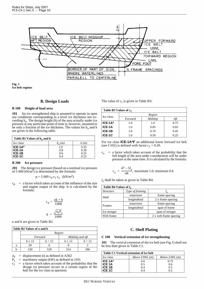
Fig. 1Ice belt regions
B. Design Loads
B 100 Height of load area101 An ice strengthened ship is assumed to operate in opensea conditions corresponding to a level ice thickness not ex-ceeding ho. The design height (h) of the area actually under icepressure at any particular point of time is, however, assumed tobe only a fraction of the ice thickness. The values for ho and hare given in the following table.
B 200 Ice pressure201 The design ice pressure (based on a nominal ice pressureof 5 600 kN/m2) is determined by the formula:
p = 5 600 cd c1 ca (kN/m2)
cd = a factor which takes account of the influence of the sizeand engine output of the ship. It is calculated by theformula:
a and b are given in Table B2.
Δf = displacement (t) as defined in A302Ps = machinery output (kW) as defined in J101c1 = a factor which takes account of the probability that the
design ice pressure occurs in a certain region of thehull for the ice class in question.
The value of c1 is given in Table B3:
For ice class ICE-1A*F an additional lower forward ice belt(see C102) is defined with factor c1 = 0.20.
ca = a factor which takes account of the probability that thefull length of the area under consideration will be underpressure at the same time. It is calculated by the formula:
la shall be taken as given in Table B4.
C. Shell Plating
C 100 Vertical extension of ice strengthening101 The vertical extension of the ice belt (see Fig.1) shall notbe less than given in Table C1.
Table B1 Values of ho and h Ice class ho (m) h (m)ICE-1A*ICE-1AICE-1BICE-1C
1.0 0.8 0.6 0.4
0.350.300.250.22
Table B2 Values of a and bRegion
Forward Midship and aftk ≤ 12 k > 12 k ≤ 12 k > 12
a 30 6 8 2b 230 518 214 286
cd ak b+1000
---------------=
kΔfPs
1000---------------=
Table B3 Values of c1
Ice classRegion
Forward Midship AftICE-1A* 1.0 1.0 0.75ICE-1A 1.0 0.85 0.65ICE-1B 1.0 0.70 0.45ICE-1C 1.0 0.50 0.25
Table B4 Values of laStructure Type of framing la
Shell transverse frame spacing
longitudinal 2 x frame spacing
Framestransverse frame spacing
longitudinal span of frameIce stringer span of stringerWeb frame 2 x web frame spacing
Table C1 Vertical extension of ice beltIce class Above UIWL (m) Below LIWL (m)ICE 1A*ICE 1AICE 1BICE 1C
0.60.50.40.4
0.750.60.50.5
ca47 5la–
44-------------------, maximum 1.0, minimum 0.6=
DET NORSKE VERITAS

Rules for Ships, July 2007 Pt.5 Ch.1 Sec.3 – Page 11
102 In addition the following areas shall be strengthened:Fore foot: For ice class ICE-1A* and ICE-1A*F the shell plat-ing below the ice belt from the stem to a position five mainframe spaces abaft the point where the bow profile departsfrom the keel line shall have at least the thickness required inthe ice belt in the midship region, calculated for the actualframe spacing.Upper forward ice belt: For ice classes ICE-1A* and ICE-1Aon ships with an open water service speed equal to or exceed-ing 18 knots, the shell plate from the upper limit of the ice beltto 2 m above it and from the stem to a position at least 0.2 Labaft the forward perpendicular, shall have at least the thick-ness required in the ice belt in the midship region, calculatedfor the actual frame spacing.
Guidance note:A similar strengthening of the bow region is advisable also for aship with a lower service speed, when it is, e.g. on the basis of themodel tests, evident that the ship will have a high bow wave.
---e-n-d---of---G-u-i-d-a-n-c-e---n-o-t-e---
For ice class ICE-1A*F the upper forward ice belt shall be tak-en 3 m above the normal ice belt, extending within the forwardregion.Lower forward ice belt: For ice class ICE-1A*F a lower for-ward ice belt below the normal ice belt is defined covering theforward region aft of the forefoot and down to the lower turnof bilge.103 Sidescuttles shall not be situated in the ice belt. If theweather deck in any part of the ship is situated below the upperlimit of the ice belt (e.g. in way of the well of a raised quarterdeck), the bulwark shall be given at least the same strength asis required for the shell in the ice belt. The strength of the con-struction of the freeing ports shall meet the same requirements.
C 200 Plate thickness in the ice belt201 For transverse framing the thickness of the shell platingshall be determined by the formula:
For longitudinal framing the thickness of the shell plating shallbe determined by the formula:
p PL = 0.75 pp = as given in B200.
x1 =
x2 =
= 1.4 − 0.4 (h/s); when 1 ≤ h/s < 1.8 = 0.35 + 0.183 (h/s) for 1.8 ≤ h/s < 3 = 0.9 for h/s > 3h = as given in B100σ F = yield stress of the material (N/mm2)tc = increment for abrasion and corrosion (mm); normally
2 mm. If a special surface coating, by experienceshown capable to withstand the abrasion of ice, is ap-plied and maintained, lower values may be approved.
202 For ice class ICE-1A*F the following additional re-quirements are given:
— bottom plating in the forward region (below the lower for-ward ice belt defined in 102) shall have a thickness not lessthan:
— side and bottom plating in the aft region below the ice beltshall have a thickness not less than:
D. FramesD 100 Vertical extension of ice framing101 The vertical extension of the ice strengthening of theframing shall be at least as given in Table D1:
Where an upper forward ice belt is required (see C102), the icestrengthened part of the framing shall be extended at least tothe top of this ice belt. 102 Where the ice strengthening would go beyond a deck ora tank top by not more than 250 mm, it can be terminated atthat deck or tank top.
D 200 Transverse frames201 The section modulus of a main or intermediate trans-verse frame shall be calculated by the formula:
p = ice pressure as given in B200h = height of load area as given in B100
mt =
mo = values as given in Table D2.
t 21.1sx1 p PL
σ F------------------ tc (mm)+=
t 21.1sp PL
x2σ F------------ tc (mm)+=
1.3 4.2
h s⁄ 1.8+( )2---------------------------------– , maximum 1.0
0.6 0.4h s⁄( )
---------------- , when h/s 1≤+
Table D1 Vertical extension of ice strengthening of the framingIce class Region Above UIWL
(m)Below LIWL
(m)
ICE- 1A*Fforward 1.2
to double bottom or
below top of floors
midship 1.2 1.6aft 1.2 1.2
ICE-1A*
from stem to 0.3 L abaft it 1.2
to double bottom or
below top of floors
abaft 0.3 L from stem 1.2 1.6
midship 1.2 1.6aft 1.2 1.2
ICE-1A, 1B, 1C
from stem to 0.3 L abaft it 1.0 1.6
abaft 0.3 L from stem 1.0 1.3
midship 1.0 1.3aft 1.0 1.0
t 0.7 s 0.8+( ) 235Lσ F
------------- (mm), minimum 12 mm=
t 0.6 s 0.8+( ) 235Lσ F
------------- (mm), minimum 10 mm=
Z p s h lmtσ F---------------103 cm3( )=
7mo7 5h l⁄–------------------------
DET NORSKE VERITAS

Rules for Ships, July 2007Pt.5 Ch.1 Sec.3 – Page 12
The boundary conditions are those for the main and intermedi-ate frames. Possible different conditions for main and interme-diate frames are assumed to be taken care of by interactionbetween the frames and may be calculated as mean values.Load is applied at mid span.If the ice belt covers less than half the span of a transverseframe, (b < 0.5 l) the following modified formula may be usedfor the section modulus:
b = distance in m between upper or lower boundary of theice belt and the nearest deck or stringer within the icebelt.
Where less than 15% of the span, l, of the frame is situatedwithin the ice-strengthening zone for frames as defined inD101, ordinary frame scantlings may be used.202 Upper end of transverse framing
1) The upper end of the strengthened part of a main frame andof an intermediate ice frame shall be attached to a deck oran ice stringer (see E).
2) Where an intermediate frame terminates above a deck oran ice stringer which is situated at or above the upper limitof the ice belt (see C100) the part above the deck or string-
er may have the scantlings required for an unstrengthenedship and the upper end be connected to the adjacent mainframes by a horizontal member of the same scantlings asthe main frame. Such an intermediate frame can also beextended to the deck above and if this is situated more than1.8 metre above the ice belt the intermediate frame neednot be attached to that deck, except in the Forward region.
203 Lower end of transverse framing
1) The lower end of the strengthened part of a main frame andof an intermediate ice frame shall be attached to a deck,tank top or ice stringer (see E).
2) Where an intermediate frame terminates below a deck,tank top or ice stringer which is situated at or below thelower limit of the ice belt (see C100), the lower end to beconnected to the adjacent main frames by a horizontalmember of the same scantlings as the frames.
D 300 Longitudinal frames301 The section modulus of a longitudinal frame shall be cal-culated by the formula:
The shear area of a longitudinal frame shall be:These formulae assume that the longitudinal frame is attachedto supporting structure as required in 401.
x3 = factor which takes account of the load distribution toadjacent frames: x3 = (1 − 0.2 h/s)
x4 = factor which takes account of the concentration of loadto the point of support: x4 = 0.6
p = ice pressure as given in B200h = height of load area as given in B100m1 = boundary condition factor; m1 = 11 shall be used for
continuous longitudinals. Where the boundary condi-tions deviate significantly from a continuous beam, asmaller factor may be required.
D 400 Structural details401 Within the ice strengthened area all frames shall be ef-fectively attached to all supporting structures. Longitudinal ortransverse frames crossing supporting structures, such as webframes or stringers, shall be connected to these structures onboth sides (by collar plates or lugs in way of cut-outs). Brackets or top stiffeners shall be fitted, in order to provideproper transfer of forces to supporting elements, as necessary.Connection of non-continuous frames to supporting structuresshall be made by brackets or similar construction. When abracket is installed, it has to have at least the same thickness asthe web plate of the frame, and the edge shall be appropriatelystiffened against buckling.402 For ice class ICE-1A*F and ICE-1A*, for ice class ICE-1A in the forward and midship regions and for ice classes ICE-1B and ICE-1C in the forward region, the following shall ap-ply in the ice strengthened area:
Table D2 Values of moBoundary condi-tion
mo Example
7 Frames in a bulk carrier with top wing tanks
6 Frames extending from the tank top to a single deck
5.7 Continuous frames between several decks or stringers
5 Frames extending between two decks only
Z ps h b l b–( )2
σF l2---------------------------------- 103 cm3( )=
Zx3 x4 p h l2
m1σF-------------------------- 103 cm3( )=
A8.7 x3p h l
σF------------------------- cm2( )=
DET NORSKE VERITAS

Rules for Ships, July 2007 Pt.5 Ch.1 Sec.3 – Page 13
1) Frames which are not at a straight angle to the shell shallbe supported against tripping by brackets, intercostals,stringers or similar at a distance preferably not exceeding1.3 m.Transverse frames perpendicular to shell which are of un-symmetrical profiles shall have tripping preventions if thespan is exceeding 4.0 m.
2) Frames and girder webs shall be attached to the shell bydouble continuous welds. No scalloping is allowed (ex-cept when crossing shell plate butts).
3) The web thickness of the frames shall at least be one halfof the thickness of the shell plating, calculated for a framespacing of 0.45 m, assuming a yield stress of the plate notmore than that used for the frame. However, the web thick-ness shall be minimum 9 mm.Where there is a deck, tank top or bulkhead in lieu of aframe, the plate thickness of this shall be as above, to adepth corresponding to the height of adjacent frames.
E. Ice Stringers E 100 Stringers within the ice belt101 The section modulus of a stringer situated within the icebelt (see C100) shall be calculated by the formula:
The shear area shall not be less than:
p = ice pressure as given in B200h = height of load area as given in B100
The product p h shall not be taken as less than 300l = span of stringer (m)m1 = boundary condition factor as given in D301.
E 200 Stringers outside the ice belt201 The section modulus of a stringer situated outside the icebelt but supporting ice strengthened frames shall be calculatedby the formula:
The shear area shall not be less than:
p = ice pressure as given in B200h = height of load area as given in B100
The product p h shall not be taken as less than 300.
l = span of stringer (m)m1 = boundary condition factor as given in D301 ls = the distance to the adjacent ice stringer(m)hs = the distance to the ice belt (m).
E 300 Deck strips301 Narrow deck strips abreast of hatches and serving as icestringers shall comply with the section modulus and shear arearequirements in 100 and 200 respectively. In the case of verylong hatches the lower limit of the product p h may be reducedto 200.302 Regard shall be paid to the deflection of the ship's sidesdue to ice pressure in way of very long hatch openings, whendesigning weatherdeck hatch covers and their fittings.
F. Web FramesF 100 Design load101 The load transferred to a web frame from an ice stringeror from longitudinal framing shall be calculated by the formu-la:
F = p h s (kN)
p = ice pressure as given in B200, when calculating factorca, however, la shall be taken as 2 s
h = height in m of load area as given in B100
The product ph shall not be taken less than 300.
s = web frame spacing in m
In case the supported stringer is outside the ice belt, the load Fmay be multiplied by:
as given in E201.
Fig. 2Web frame
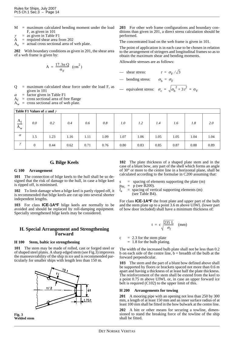
F 200 Section modulus and shear area201 For a web frame simply supported at the upper end andfixed at the lower end (see Fig.2), the section modulus require-ment is given by:
Z 0.9 p h l2
m1σ F--------------------- 103 cm3( )=
A 7.8 p h lσ F
------------------- cm2( )=
Z 0.95 p h l2
m1σ F------------------------ 1
hsls-----–⎝ ⎠
⎛ ⎞ 103 cm3( )=
A 8.2 p h lσ F
------------------- 1hsls-----–⎝ ⎠
⎛ ⎞ cm2( )=
1hsls-----–⎝ ⎠
⎛ ⎞
Z MσF------ 1
1 γ AAa------⎝ ⎠
⎛ ⎞ 2–
--------------------------103 (cm3 )=
DET NORSKE VERITAS
Rules for Ships, July 2007Pt.5 Ch.1 Sec.3 – Page 14
M = maximum calculated bending moment under the loadF, as given in 101
γ = as given in Table F1A = required shear area from 202Aa = actual cross sectional area of web plate.
202 With boundary conditions as given in 201, the shear areaof a web frame is given by:
Q = maximum calculated shear force under the load F, asgiven in 101
α = factor given in Table F1Af = cross sectional area of free flangeAw = cross sectional area of web plate.
203 For other web frame configurations and boundary con-ditions than given in 201, a direct stress calculation should beperformed.The concentrated load on the web frame is given in 101.The point of application is in each case to be chosen in relationto the arrangement of stringers and longitudinal frames so as toobtain the maximum shear and bending moments.Allowable stresses are as follows:
— shear stress:
— bending stress:
— equivalent stress:
G. Bilge KeelsG 100 Arrangement101 The connection of bilge keels to the hull shall be so de-signed that the risk of damage to the hull, in case a bilge keelis ripped off, is minimised.102 To limit damage when a bilge keel is partly ripped off, itis recommended that bilge keels are cut up into several shorterindependent lengths.103 For class ICE-1A*F bilge keels are normally to beavoided and should be replaced by roll-damping equipment.Specially strengthened bilge keels may be considered.
H. Special Arrangement and Strengthening Forward
H 100 Stem, baltic ice strengthening101 The stem may be made of rolled, cast or forged steel orof shaped steel plates. A sharp edged stem (see Fig.3) improvesthe manoeuvrability of the ship in ice and is recommended par-ticularly for smaller ships with length less than 150 m.
Fig. 3Welded stem
102 The plate thickness of a shaped plate stem and in thecase of a blunt bow, any part of the shell which forms an angleof 30° or more to the centre line in a horizontal plane, shall becalculated according to the formulae in C200 assuming that:
s = spacing of elements supporting the plate (m)pPL = p (see B200).la = spacing of vertical supporting elements (m)
(see Table B4).
For class ICE-1A*F the front plate and upper part of the bulband the stem plate up to a point 3.6 m above UIWL (lower partof bow door included) shall have a minimum thickness of:
c = 2.3 for the stem plate = 1.8 for the bulb plating.
The width of the increased bulb plate shall not be less than 0.2b on each side of the centre line, b = breadth of the bulb at theforward perpendicular.103 The stem and the part of a blunt bow defined above shallbe supported by floors or brackets spaced not more than 0.6 mapart and having a thickness of at least half the plate thickness.The reinforcement of the stem shall be extend from the keel toa point 0.75 m above UIWL or, in case an upper forward icebelt is required (C102) to the upper limit of this.
H 200 Arrangements for towing201 A mooring pipe with an opening not less than 250 by 300mm, a length of at least 150 mm and an inner surface radius of atleast 100 mm shall be fitted in the bow bulwark at the centre line.202 A bitt or other means for securing a towline, dimen-sioned to stand the breaking force of the towline of the shipshall be fitted.
A 17.3α QσF
-------------------- (cm2 )=τ σF 3⁄=
σb σF=
σc σb2 3τ2+ σF= =
Table F1 Values of α and γ
0.0 0.2 0.4 0.6 0.8 1.0 1.2 1.4 1.6 1.8 2.0
α 1.5 1.23 1.16 1.11 1.09 1.07 1.06 1.05 1.05 1.04 1.04
γ 0 0.44 0.62 0.71 0.76 0.80 0.83 0.85 0.87 0.88 0.89
AfAw--------
t c 235 Lσf
-------------- (mm)=
DET NORSKE VERITAS

Rules for Ships, July 2007 Pt.5 Ch.1 Sec.3 – Page 15
203 On ships with a displacement not exceeding 30 000 tonsthe part of the bow which extends to a height of at least 5 mabove the UIWL and at least 3 m aft of the stem, shall bestrengthened to take the stresses caused by fork towing. Forthis purpose intermediate frames shall be fitted and the framingshall be supported by stringers or decks.204 It shall be noted that for ships of moderate size (displace-ment not exceeding 30 000 tons) fork towing in many situa-tions is the most efficient way of assisting in ice. Ships with abulb protruding more than 2.5 m forward of the forward per-pendicular are often difficult to tow in this way. The adminis-trations reserve the right to deny assistance to such ships if thesituation so warrants.
I. Special Arrangement and Strengthening Aft
I 100 Stern101 The introduction of new propulsion arrangements withazimuthing thrusters or “podded” propellers, which provide animproved manoeuvrability, will result in increased ice loadingof the aft region and stern area. This fact should be consideredin the design of the aft/stern structure.102 An extremely narrow clearance between the propellerblade tip and the stern frame shall be avoided as a small clear-ance would cause very high loads on the blade tip.103 On twin and triple screw ships the ice strengthening ofthe shell and framing shall be extended to the double bottomfor 1.5 metre forward and aft of the side propellers.104 Shafting and stern tubes of side propellers are normallyto be enclosed within plated bossings. If detached struts areused, their design, strength and attachment to the hull shall beduly considered.For class ICE-1A*F the skin plating of propeller shaft bossingsshall not be less than:
105 A wide transom stern extending below the UIWL willseriously impede the capability of the ship to run astern in ice,which is most essential. Therefore a transom stern shall not beextended below the UIWL if this can be avoided. If unavoida-ble, the part of the transom below the UIWL shall be kept asnarrow as possible. The part of a transom stern situated withinthe ice belt shall be strengthened as for the midship region.
I 200 Rudder and steering arrangements 201 The scantlings of rudder, rudder post, rudder stock, pin-tles, steering gear etc. as well as the capacity of the steeringgear shall be determined according to the rules. The maximumservice speed of the ship to be used in these calculations is,however, not to be taken less than that stated below:
If the actual maximum service speed of the ship is higher, thatspeed shall be used.When calculating the rudder force according to the formulagiven in Pt.3 Ch.3 Sec.2 D and with the speed V in ahead con-dition as given above, the factors k1 = k2 = 1.0 irrespective ofcondition, rudder profile type or arrangement. In the asterncondition half the speed values shall be used.
202 For the ice classes ICE-1A* and ICE-1A the rudderstock and the upper edge of the rudder shall be protectedagainst ice pressure by an ice knife or equivalent means.
Guidance note:Upper forward part of rudder and forward part of rudder hornshould be protected against abrasion by a special coating or in-crease in thickness.
---e-n-d---of---G-u-i-d-a-n-c-e---n-o-t-e---
203 For ice classes ICE-1A* and ICE-1A due regard shall bepaid to the excessive loads caused by the rudder being forcedout of the midship position when backing into an ice ridge.204 Relief valves for hydraulic pressure shall be effective. Thecomponents of the steering gear shall be dimensioned to stand theyield torque of the rudder stock. Where possible rudder stoppersworking on the blade or rudder head shall be fitted.205 Parts of rudder within the ice belt shall have local thick-ness at least equivalent to the side shell in the afterbody.
J. MachineryJ 100 Engine output101 Definition of engine outputThe engine output PS is the maximum output the propulsion ma-chinery can continuously deliver to the propeller(s). If the outputof the machinery is restricted by technical means or by any regu-lations applicable to the ship, PS shall be taken as the restrictedoutput.102 Documentation on boardMinimum engine output corresponding to the ice class shall begiven in the Classification Certificate.103 Required engine output for ice classesDefinitionsThe dimensions of the ship and some other parameters are de-fined below:
L = length of the ship between the perpendiculars (m)LBOW = length of the bow (m), Fig.4L PAR = length of the parallel midship body (m), Fig.4B = maximum breadth of the ship (m)T = actual ice class draughts of the ship (m) according to
A301A wf = area of the waterline of the bow (m2), Fig.4α = the angle of the waterline at B/4 (°), Fig.4ϕ1 = the rake of the stem at the centreline (°), Fig.4ϕ2 = the rake of the bow at B/4 (°), Fig.4DP = diameter of the propeller or outer diameter of nozzle
for the nozzle propeller, maximum 1.2 times propel-ler diameter (m)
HM = thickness of the brash ice in mid channel (m)HF = thickness of the brash ice layer displaced by the bow
(m).RCH = resistance (in Newton) of the ship in a channel with
brash ice and a consolidated layer (see formula in 104)Ke = factor depending on no. of propellers, CPP (or sim-
ilar), fixed pitch type (see Table J2)Ps = minimum engine outputC = empirical coefficients (misc. sub index)f = empirical factors (misc. sub index)g = empirical factors (misc. sub index).Range of validityThe range of validity of the formulae for powering require-ments in 104 is presented in Table J1. When calculating the pa-
Table I1 Maximum service speedIce class Maximum service speed ICE-1A*ICE-1AICE-1BICE-1C
20 knots18 knots16 knots14 knots
t 0.9 s 0.8+( ) 235 Lσf
-------------- (mm).=
DET NORSKE VERITAS

Rules for Ships, July 2007Pt.5 Ch.1 Sec.3 – Page 16
rameter DP/T, T shall be measured at UIWL.
If the ship’s parameter values are beyond the ranges defined inTable J1, other methods for determining RCH shall be used asdefined in 105.
Fig. 4Definitions
104 The engine output requirement shall be calculated for:
— Upper Ice Waterlines (UIWL) and— Lower Ice Waterlines (LIWL),
as defined in Sec.1 B.In the calculations the ship's parameters which depend on thedraught shall be determined at the appropriate draught, but Land B shall be determined only at the UIWL. The engine out-put shall not be less than the greater of these two outputs.The engine output PS shall not be less than that determined bythe formulae and in no case less than given in Table J3:
Guidance note:“New ships” – see A102 Guidance note.For “existing ICE-1A and ICE-1A* ships” see Pt.7 Ch.2 Sec.2A.
---e-n-d---of---G-u-i-d-a-n-c-e---n-o-t-e---
RCH is the resistance in Newton of the ship in a channel withbrash ice and a consolidated layer:
Cμ = 0.15 cosϕ2 + sinψ sinαCμ ≥ 0.45 (minimum value)
Cψ = 0.047ψ − 2.115 and 0 if ψ ≤ 45°HF = 0.26 + (HMB)0.5
HM = 1.0 for ICE-1A and ICE-1A*= 0.8 for ICE-1B= 0.6 for ICE-1C
C1 and C2 take into account a consolidated upper layer of thebrash ice and can be taken as zero for ice class ICE-1A, ICE-1B and ICE-1C.
Table J1 Parameter validity rangeParameter Minimum Maximumα [degrees] 15 55ϕ1 [degrees] 25 90ϕ2 [degrees] 10 90L [m] 65.0 250.0B [m] 11.0 40.0
T [m] 4.0 15.0LBOW/L 0.15 0.40LPAR/L 0.25 0.75DP /T 0.45 0.75Awf /(L*B) 0.09 0.27
Table J2 Value of factor KePropeller type or machinery
Numbers of propellers
Controllable pitch propeller or electric or hydraulic propulsion
machineryFixed pitch propeller
1 propeller 2.03 2.262 propellers 1.44 1.63 propellers 1.18 1.31
Table J3 Minimum engine output PSICE-1A, ICE-1B and ICE-1C 1 000 kWICE-1A* 2 800 kW
PS Ke
RCH1000------------⎝ ⎠
⎛ ⎞
DP-----------------
32---
(kW)=
RCH C1 C2 C3Cμ HF HM+( )2 B CψHF+( )
C4LPARHF2 C5
LT
B2-------⎝ ⎠
⎛ ⎞ 3AwfL
---------- (N)+
+ + +=
DET NORSKE VERITAS

Rules for Ships, July 2007 Pt.5 Ch.1 Sec.3 – Page 17
For ice class ICE-1A*:
For a ship with a bulbous bow, ϕ1 shall be taken as 90°.
f1 = 23 (N/m2)f2 = 45.8 (N/m)f3 = 14.7 (N/m)f4 = 29 (N/m2)g1 = 1 530 (N)g2 = 170 (N/m)g3 = 400 (N/m1.5)C3 = 845 (kg/(m2s2))C4 = 42 (kg/(m2s2))C5 = 825 (kg/s2)
105 Other methods of determining Ke or RCH
For an individual ship, in lieu of the Ke or RCH values definedin Table J2 and 104, the use of Ke or RCH values based on moreexact calculations or values based on model tests may be ap-proved. Such approval will be given on the understanding thatit can be revoked if experience of the ship’s performance inpractice motivates this.
Guidance note:For ships having the propulsion power determined by model testsor by means other than the rule formula, additional approval byFMA or SMA is necessary for ships requesting Finnish ice cer-tificate.
---e-n-d---of---G-u-i-d-a-n-c-e---n-o-t-e---
The design requirement for ice classes shall be a minimum speedof 5 knots in the following brash ice channels (see Table J4):
J 200 Design loads for propeller and shafting201 The formulae for scantlings are based on the followingloads:
To = mean torque of propulsion engine at maximum con-tinuous rating in Nm(If multi-engine plant, To is the mean torque in anactual branch or after a common point. To is alwaysreferred to engine r.p.m.)
Tho = mean propeller thrust in N at maximum continuousspeed
R = as given in 301.Tice = ice torque in Nm (referred to propeller r.p.m.) and
found from Table J5.
J 300 Propeller301 The particulars governing the requirements for scant-lings are:
R = propeller radius (m)Hr = pitch in m at radius in questionθ = rake in degrees at blade tip (backward rake positive)Z = number of bladest = blade thickness in mm at cylindrical section consid-
eredt0.25 = t at 0.25 Rt0.35 = t at 0.35 Rt0.6 = t at 0.6 Rcr = blade width in m at cylindrical section consideredc0.25 = cr at 0.25 Rc0.35 = cr at 0.35 Rc0.6 = cr at 0.6 Re = distance between skew line and generatrix in m at cy-
lindrical section considered, positive when skew line isforward of generatrix.
e0.6 = e at 0.6 Re1.0 = e at 1.0 Ru = gear ratio:
If the shafting system is directly coupled to engine, u = 1.
no = propeller speed at maximum continuous output, forwhich the machinery shall be approved, in revolutionsper minute.
302 Propellers and propeller parts (defined in Pt.4 Ch.5Sec.1 A103) shall be of steel or bronze as specified in Pt.2Ch.2. Nodular cast iron of Grade NV 1 and NV 2 may be usedfor relevant parts in CP-mechanism. Other type of nodular castiron with elongation ≥ 12% may be accepted upon special con-sideration for same purposes..303 Skewed propellers will be especially considered with re-spect to the risk of blade bending at outer sections if fsk (see304) exceeds:
— 1.10, in case propeller direction of rotation cannot be re-versed
— 1.05, in case propeller direction of rotation can be re-versed.
304 The blade thickness of the cylindrical sections at 0.25 R(fixed pitch propellers only) and at 0.35 R shall not be less than:
Table J4 Values of HMIce class HMICE-1A* 1.0 m and a 0.1 m thick consolidated layer of iceICE-1A 1.0 mICE-1B 0.8 mICE-1C 0.6 m
C1 f1BLPAR
2TB---- 1+
-------------------- 1 0.021ϕ1+( ) f2B f3LBOW f4BLBOW+ +( )+=
C2 1 0.063ϕ1+( ) g1 g2B+( ) g3 1 1.2TB----+⎝ ⎠
⎛ ⎞ B2
L-------+=
ψ arctanϕ2tanαsin
--------------⎝ ⎠⎛ ⎞=
The following shall apply: 20 LT
B2-------⎝ ⎠
⎛ ⎞ 35≥ ≥
Table J5 Values of TiceIce class Open propeller Ducted propeller ICE-1A* 84 000 R2 62 400 R2
ICE-1A 62 400 R2 52 000 R2
ICE-1B 52 000 R2 47 600 R2
ICE-1C 47 600 R2 42 800 R2. R > 3 m40 400 R2. R < 1.5 m 1)
1) For 1.5 m < R < 3 m, Tice may be found by linear interpolation.
u engine r.p.m.propeller r.p.m.--------------------------------------------=
t C12RK1 U2C4 0.2+( ) K4+
Zcr K( Mat U1 U2Sr )–------------------------------------------------------------- (mm)=
DET NORSKE VERITAS

Rules for Ships, July 2007Pt.5 Ch.1 Sec.3 – Page 18
The thickness at 0.6 R shall not be less than:
U1 and U2 = material constants to be taken as given in Pt.4Ch.5 Sec.1 Table B1.
For fixed blade propellers
For controllable pitch propellers
K4 = ki Z Tice sinαC1, C2, C3, C4 = as given in Table J6.
A = q0 + q1 d + q2 d2 + q3 d3
q0, q1, q2, q3 = as given in Table J7.
d =
d =
ki = 96 at 0.25 R = 92 at 0.35 RKMat = 1.0 for stainless steel propellers = 0.8 for other materials
sin α =
=
K1 as given above is only valid for propulsion by diesel en-gines (by about zero speed, it is assumed 85% thrust and 75%torque for fixed pitch propellers and 125% thrust and 100%torque for controllable pitch propellers).For turbine, diesel-electric or similar propulsion machinery K1will be considered in each particular case.
Guidance note:K1 ≥ 1.1 may be used if nothing else is documented
---e-n-d---of---G-u-i-d-a-n-c-e---n-o-t-e---
The thickness of other sections is governed by a smooth curveconnecting the above section thicknesses.
305 When the outer sections of the propeller blade is not sub-ject to special consideration according to J303, the blade tipthickness at the radius 0.95 R shall not be less than given bythe following formulae:
For ICE-1A*:
For ICE-1A, ICE-1B or ICE-1C
σb = ultimate tensile strength in N/mm2 of propeller bladematerial.
The thickness of the blade edge and the propeller tip shall notbe less than 50% of minimum t as given above, measured at1.25 t from the edge or tip, respectively. For propellers wherethe direction of rotation is not reversible, this requirement onlyapplies to the leading edge and propeller tip.306 If found necessary by the torsional vibration calcula-tions, minor deviations from the dimensions given in 304 and305 may be approved upon special consideration.307 The section modulus of the blade bolt connection re-ferred to an axis tangentially to the bolt pitch diameter, shallnot be less than:
σb = tensile strength of propeller blade material (N/mm2)σy = yield stress of bolt material (N/mm2)
The propeller blade foot shall have a strength (including stressconcentration) not less than that of the bolts.308 Fitting of the propeller to the shaft is given in Pt.4 Ch.4Sec.1 as follows:
— Flanged connection in B300 — Keyless cone connection in B400— Keyed cone connection in B500
(Considering 0°C seawater temperature)
t t0.350.45 fsk c0.35⋅ ⋅
c0.6--------------------------------------- (mm)=
20.16.0
sk Ree
1f ⎟⎠
⎞⎜⎝
⎛ −+=
Sr = 2Rno100
-------------⎝ ⎠⎛ ⎞
2C2θ C3+( )
K1 = A1d T ho0.85 A2+0.75uTo
R---------------------⎝ ⎠
⎛ ⎞
K1 = A1d T ho1.25 A2uToR
---------+
2πRHr
----------- for fixed blade propellers
2πR0.7Hr-------------- for controllable pitch propellers
4
d2 16+---------------------- at 0.25 R
2.86
d2 8.18+--------------------------- at 0.35 R
Table J6 Values of C1, C2, C3, C4r 0.25 R 0.35 R 0.6 R
C1 0.278 0.258 0.150C2 0.026 0.025 0.020C3 0.055 0.049 0.034C4 1.38 1.48 1.69
Table J7 Values of q0, q1, q2, q3R q0 q1 q2 q3
0.25 R A1A2
8.3063.80
0.370-4.500
-0.340-0.640
0.0300.0845
0.35 R A1A2
9.5557.30
-0.015-7.470
-0.339-0.069
0.03220.0472
0.6 R A1A2
14.6052.90
-1.720-10.300
-0.1030.667
0.02030.0
t 20 4R+( ) 490σb
---------- (mm)=
t 15 4R+( ) 490σb
---------- (mm)=
Wb 0.1 c0.35 t0.352 σb
σy------ cm3( )=
DET NORSKE VERITAS

Rules for Ships, July 2007 Pt.5 Ch.1 Sec.3 – Page 19
If the propeller is bolted to the propeller shaft, the bolt connec-tion shall have at least the same bending strength as the propel-ler shaft.The strength of the propeller shaft flange (including stress con-centration) shall be at least the same as the strength of the bolts.
J 400 Propulsion shaft line reinforcement401 Determination of factors for ice reinforcement of shaftline.
u = as defined in 301I = equivalent mass moment of inertia in kgm2 based on
torque of all parts on engine side of component underconsideration.
Masses rotating with engine speed to be transformed accordingto:
Iequiv = I actual u2
In propulsion systems with hydraulic coupling, torque convert-er or electromagnetic slip coupling, the masses in front of thecoupling shall not be taken into consideration.
It = equivalent mass moment of inertia of propulsion sys-tem in kgm2. (Masses in front of hydraulic or electro-magnetic slip coupling shall not be taken intoconsideration.)
402 Application factor for diesel and or turbine machinery ingeneral:
403 Application factor for electric motor machinery or dieselmachinery with hydrodynamic torque converter:
1) Diesel engine with torque converter or hydrodynamic cou-pling:
TTC max = maximum possible transmittable torque throughconverter and or coupling.
2) Electric motor drive:
Tmax = motor peak torque (steady state condition).Alternatively to the above criteria, the ice impact load may bedocumented by simulation of the transient dynamic responsein the time domain. For branched systems, such simulation isin general recommended.404 The diameter of the propeller shaft at the aft bearingshall not be less than:
σb = tensile strength of propeller blade material (N/mm2)σy = yield strength of propeller shaft material (N/mm2)c0.35 = as defined in 301t0.35 = as defined in 301.
Between the aft and second aft bearing, the shaft may be even-ly tapered to 1.22 times the diameter of the intermediate shaft,as required for the main class.Forward of the after peak bulkhead, the shaft may be evenly ta-pered down to 1.05 times the rule diameter of intermediate shaft,
but not less than the actual diameter of the intermediate shaft.405 The diameter of intermediate shafts shall be determinedbased on methods given in Pt.4 Ch.4 Sec.1 B201.
a) When using the classification note 41.4 the necessary rein-forcement is determined by using KAice in the given criteria.
b) With KAice ≤ 1.4 the method in Pt.4 Ch.4 Sec.1 B206 maybe used, i.e. no ice reinforcement beyond 1A1 rules.
When using the method in Pt.4 Ch.4 Sec.1 B208, the minimumdiameter in item 3 of that paragraph shall be multiplied with:
but not less than 1.0In item 4 of same paragraph, the vibratory torsional stress τv isreplaced by:
and shall not exceed τC.406 Regarding shaft connections, use KAice in Pt.4 Ch.4Sec.1 as follows:
— Flange connections, see B300— Shrink fit connections, see B400— Keyed connections, see B500
407 The thrust bearing shall be dimensioned for a thrust ac-cording to:
408 For reduction gears, use KAice in Pt.4 Ch.4 Sec.2.409 For clutches, use KAice in Pt.4 Ch.4 Sec.3 B100410 For torsional elastic coupling, use KAice in Pt.4 Ch.4Sec.5 B200.411 For crank shafts in direct coupled diesel engines, seePt.4 Ch.3 Sec.1 B506.
J 500 Miscellaneous machinery requirements501 Starting arrangementsThe capacity of the air receivers shall be according to the re-quirements in Pt.4 Ch.6 Sec.5 I.If the air receivers serve any other purposes than starting thepropulsion engine, they shall have additional capacity suffi-cient for these purposes.The capacity of the air compressors shall be sufficient for charg-ing the air receivers from atmospheric to full pressure in one (1)hour, except for a ship with the ice class ICE-1A* if its propul-sion engine has to be reversed for going astern, in which case thecompressors shall be able to charge the receivers in half an hour.502 Sea inlet and cooling water systems.The cooling water system shall be designed to ensure supply ofcooling water when navigating in ice. The sea cooling waterinlet and discharge for main and auxiliary engines shall be soarranged that blockage of strums and strainers is prevented.For this purpose at least one cooling water inlet chest shall bearranged as follows:
1) The sea inlet shall be situated near the centre line of theship and well aft if possible. The inlet grids shall be spe-cially strengthened.
2) As a guidance for design the volume of the chest shall beabout one cubic metre for every 750 kW engine output ofthe ship including the output of the auxiliary engines nec-essary for the ship's service.
T0
iceAice IuT
IT1K +=
t0
ice
0
maxTCAice IuT
ITT
TK +=
T0
ice
0
maxAice IuT
ITT
TK +=
dp 11.5σbC0.35t0.35
2
σy-------------------------------
⎝ ⎠⎜ ⎟⎛ ⎞
13---
(mm)=
31
Aice4.1
K⎟⎟⎠
⎞⎜⎜⎝
⎛
( ) 0Aicev T1K5.0 ⋅−⋅=τ
Th 1.3ThoTice
R---------- (N)+=
DET NORSKE VERITAS

Rules for Ships, July 2007Pt.5 Ch.1 Sec.3 – Page 20
3) To allow for ice accumulation above the pump suction theheight of the sea chest shall not be less than:
Vs = volume of sea chest according to item 2.The suction pipe inlet shall be located not higher thanhmin/3 from top of sea chest.
4) A pipe for discharge cooling water, allowing full capacity dis-charge, shall be connected to the chest. Where the sea chestvolume and height specified in 2 and 3 are not complied with,the discharge shall be connected to both sea chests. At leastone of the fire pumps shall be connected to this sea chest orto another sea chest with de-icing arrangements.
5) The area of the strum holes shall be not less than four (4)times the inlet pipe sectional area.
If there are difficulties in meeting the requirements of 2) and 3)above, two smaller chests may be arranged for alternating in-take and discharge of cooling water. The arrangement and sit-uation otherwise shall be as above.Heating coils may be installed in the upper part of the chest orchests.Arrangements using ballast water for cooling purposes may be
useful as a reserve in ballast condition but can not be acceptedas a substitute for sea inlet chests as described above.503 Ballast systemAn arrangement to prevent freezing of the ballast water shallbe provided for in ballast tanks located fully or partly above theLIWL, adjacent to the ship's shell, and needed to be filled foroperation in ice conditions according to A302. For this purposethe following ambient temperatures shall be taken as designconditions:
— Sea water temperature: 0°C— Air temperature: –10°C
Necessary calculations shall be submitted.When a tank is situated partly above the LIWL, an air-bubblingarrangement or a vertical heating coil, capable of maintainingan open hole in the ice layer, will normally be accepted.The required heat-balance calculations may then be omitted.
Guidance note:It is assumed that, before pumping of ballast water is com-menced, proper functioning of level gauging arrangements isverified and air pipes are checked for possible blockage by ice.
---e-n-d---of---G-u-i-d-a-n-c-e---n-o-t-e---
hmin 1.5 Vs3≥
DET NORSKE VERITAS

Rules for Ships, July 2007 Pt.5 Ch.1 Sec.4 – Page 21
SECTION 4 VESSELS FOR ARCTIC AND ICE BREAKING SERVICE
A. General
A 100 Classification 101 The requirements in this section apply to icebreakersand to passenger and cargo vessels intended to operate unas-sisted in ice-infested waters of sub-Arctic, Arctic and/or Ant-arctic regions.102 Vessels intended for ice breaking as their main purposeand built in compliance with the following requirements maybe given one of the class notations Icebreaker ICE-05 (or -10 or -15) or Icebreaker POLAR-10 (or -20 or -30), which-ever is relevant.Vessels built for another main purpose, while also intended forice breaking, may be given the additional class notation ICE-05 (or -10 or -15) or the notation POLAR-10 (or -20 or -30).103 Arctic class vessels intended for special services whereintermediate ice condition values are relevant may, upon spe-cial consideration, be given intermediate notations (e.g. PO-LAR-25).104 For POLAR class vessels the design ambient air temper-ature on which the classification has been based will be giventhe special feature notation DAT(—x°C). For details, see Sec.7.105 For vessels with the class notation Icebreaker, and forother POLAR class vessels the maximum operational speedon which the ramming design requirements have been basedwill be stated in the “Appendix to the classification certifi-cate”. The operational speed is in no case to be taken as smallerthan stated in 300 for the various class notations.
A 200 Scope201 The following matters are covered by the classification:
— materials in structures exposed to low ambient air temper-atures
— subdivision, intact and damage stability— hull girder longitudinal and transverse strength— local hull structures exposed to ice loads— rudders and steering gears— propellers and propulsion machinery— sea suctions for cooling water— air starting systems
MDHT Mean daily high (or maximum) temperatureMDAT Mean daily average temperatureMDLT Mean daily low (or minimum) temperatureMAMDHT Monthly average of MDHTMAMDAT Monthly average of MDATMAMDLT Monthly average of MDLTMEHT Monthly extreme high temperature (ever recorded)MELT Monthly extreme low temperature (ever recorded).Mean: Statistical mean over observation period (at least 20years).Average: Average during one day and night.
A 300 Design principles and assumptions301 Each class notation is related to a particular ice conditionthat the vessel is expected to encounter. Relevant design iceconditions are as given in Table A1. In case intermediate iceconditions are relevant (see 103), nominal ice strength shall be
related to the selected nominal ice thickness.302 Vessels with the class notation Icebreaker, and otherPOLAR class vessels are expected to encounter pressure ridg-es and other ice features of significantly greater thickness thanthe average thicknesses specified in Table A1. Vessels with theclass notation POLAR only are assumed not to make repeatedramming attempts if the ice fails to break during the first (oc-casional) ram unless the vessel's speed is kept well below thedesign ramming speed. Vessels with class notation Icebreak-er may make several consecutive attempts to break the ice atmaximum ramming speed. The design speed in ice infestedwaters when ramming may occur, VRAM, shall be specified bythe builder. In general this speed shall not be taken less than:
VRAM = VB + VH (m/s)
VB = specified continuous speed, when breaking maximumaverage ice thickness
VH = speed addition in thinner ice = hice (see Table A1).
In no case the design ramming speed shall be taken less than:VRAM (minimum)
= 2.0 m/s (3.9 knots) for the notation POLAR-10 = 3.0 m/s (5.8 knots) for the notation POLAR-20 = 4.0 m/s (7.8 knots) for the notation POLAR-30.
For vessels with the class notation Icebreaker the minimumspeed is 2 m/s (3.9 knots) but not less than 1.5 times the speedspecified above when POLAR class notation is also specified.
A 400 Definitions401 General symbols and terms are also given in Sec.1 B100.402 Symbols
VRAM = design speed in m/s when ramming may occur, seealso 302
σice = nominal strength of ice in N/mm2, see Table A1hice = average ice thickness in m, see Table A1EKE = vessel's kinetic energy before ramming = 1/2 Δ (VRAM)2 (kNm)α, γ = bow shape angles, see Fig.1CWL = vessel's water line area coefficient on UIWLs = stiffener spacing in m, measured along the plating.
Stiffener web thickness may be deducted l = Stiffener span in m, measured along the top flange
of the member.For determining the section modulus and shear areaof the stiffener, the depth of stiffener on crossingpanel and 2/3 of the arm length of end bracket(s)(except at simply supported ends) may be deductedwhen deciding the span.
S = girder span in m. The web height of in-plane girdersmay be deducted
t = rule thickness of plating in mmtk = corrosion addition in mmtw = rule web thickness in mmZ = rule section modulus in cm3
AW = rule web area in cm2, defined as the web thicknesstimes the web height including thickness of flanges
A = rule cross-sectional area in cm2
DET NORSKE VERITAS
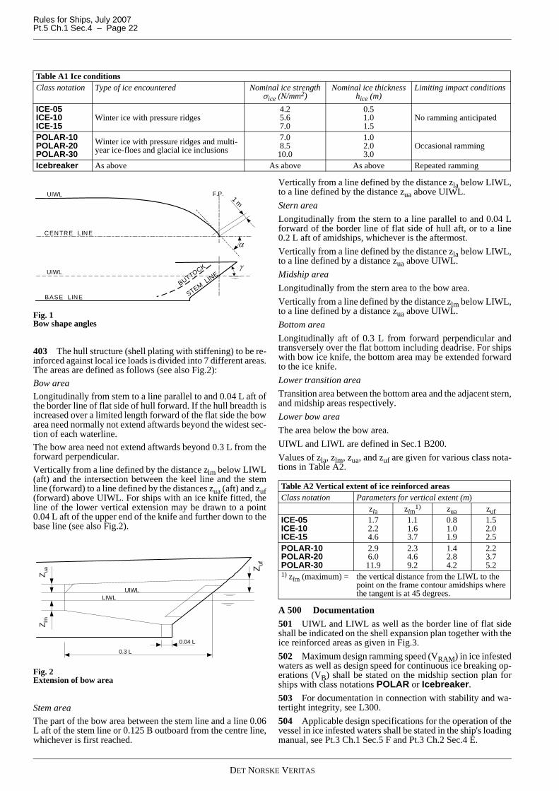
Rules for Ships, July 2007Pt.5 Ch.1 Sec.4 – Page 22
Fig. 1Bow shape angles
403 The hull structure (shell plating with stiffening) to be re-inforced against local ice loads is divided into 7 different areas.The areas are defined as follows (see also Fig.2):Bow areaLongitudinally from stem to a line parallel to and 0.04 L aft ofthe border line of flat side of hull forward. If the hull breadth isincreased over a limited length forward of the flat side the bowarea need normally not extend aftwards beyond the widest sec-tion of each waterline.The bow area need not extend aftwards beyond 0.3 L from theforward perpendicular.Vertically from a line defined by the distance zlm below LIWL(aft) and the intersection between the keel line and the stemline (forward) to a line defined by the distances zua (aft) and zuf(forward) above UIWL. For ships with an ice knife fitted, theline of the lower vertical extension may be drawn to a point0.04 L aft of the upper end of the knife and further down to thebase line (see also Fig.2).
Fig. 2Extension of bow area
Stem areaThe part of the bow area between the stem line and a line 0.06L aft of the stem line or 0.125 B outboard from the centre line,whichever is first reached.
Vertically from a line defined by the distance zla below LIWL,to a line defined by the distance zua above UIWL.Stern areaLongitudinally from the stern to a line parallel to and 0.04 Lforward of the border line of flat side of hull aft, or to a line0.2 L aft of amidships, whichever is the aftermost.Vertically from a line defined by the distance zla below LIWL,to a line defined by a distance zua above UIWL.Midship areaLongitudinally from the stern area to the bow area.Vertically from a line defined by the distance zlm below LIWL,to a line defined by a distance zua above UIWL. Bottom areaLongitudinally aft of 0.3 L from forward perpendicular andtransversely over the flat bottom including deadrise. For shipswith bow ice knife, the bottom area may be extended forwardto the ice knife.Lower transition areaTransition area between the bottom area and the adjacent stern,and midship areas respectively.Lower bow areaThe area below the bow area.UIWL and LIWL are defined in Sec.1 B200.Values of zla, zlm, zua, and zuf are given for various class nota-tions in Table A2.
A 500 Documentation501 UIWL and LIWL as well as the border line of flat sideshall be indicated on the shell expansion plan together with theice reinforced areas as given in Fig.3.502 Maximum design ramming speed (VRAM) in ice infestedwaters as well as design speed for continuous ice breaking op-erations (VB) shall be stated on the midship section plan forships with class notations POLAR or Icebreaker.503 For documentation in connection with stability and wa-tertight integrity, see L300.504 Applicable design specifications for the operation of thevessel in ice infested waters shall be stated in the ship's loadingmanual, see Pt.3 Ch.1 Sec.5 F and Pt.3 Ch.2 Sec.4 E.
Table A1 Ice conditionsClass notation Type of ice encountered Nominal ice strength
σice (N/mm2)Nominal ice thickness
hice (m)Limiting impact conditions
ICE-05 ICE-10 ICE-15
Winter ice with pressure ridges4.2 5.6 7.0
0.5 1.0 1.5
No ramming anticipated
POLAR-10 POLAR-20 POLAR-30
Winter ice with pressure ridges and multi-year ice-floes and glacial ice inclusions
7.0 8.5
10.0
1.0 2.0 3.0
Occasional ramming
Icebreaker As above As above As above Repeated ramming
F.P. 1 m
α
γ
BUTTOCK
STEMLINE
BASE LINE
UIWL
UIWL
CENTRE LINE
Z uaZ lm
Z uf
UIWLLIWL
0.3 L
0.04 L
Table A2 Vertical extent of ice reinforced areasClass notation Parameters for vertical extent (m)
zla zlm1) zua zuf
ICE-05 ICE-10 ICE-15
1.7 2.2 4.6
1.1 1.6 3.7
0.8 1.0 1.9
1.5 2.0 2.5
POLAR-10 POLAR-20 POLAR-30
2.9 6.0 11.9
2.3 4.6 9.2
1.4 2.8 4.2
2.2 3.7 5.2
1) zlm (maximum) = the vertical distance from the LIWL to the point on the frame contour amidships where the tangent is at 45 degrees.
DET NORSKE VERITAS

Rules for Ships, July 2007 Pt.5 Ch.1 Sec.4 – Page 23
Possible design specifications are:
— allowable draughts, maximum and minimum— loading conditions with respect to strength and stability— ambient temperature— design speed— ramming speed— instruction for filling of ballast tanks.
— astern operation in ice.
505 Where ice exposed plating is fitted with a special wearaddition, the plate thickness including wear addition shall begiven on the shell expansion plan in addition to the net thick-ness required by the rules.
Fig. 3Ice reinforced areas
506 Documentation requirements for stability and watertightintegrity can be found in L200.
B. Materials and Corrosion Protection
B 100 Design temperatures101 Steel grades to be used in hull structural members shallbe determined based on the design temperature for the struc-ture in question with requirements as given in Sec.7.102 For POLAR class notations steel grades in exposedstructures (external structure as defined in Sec.7) shall bebased on air temperatures lower than those generally anticipat-ed for world wide operation. Unless a service restriction nota-tion is also given, limiting the navigation to specified areasand/or time of year, the design temperature shall not be takenhigher than -30°C (corresponding extreme low temperature -50ºC).For operation in lower design temperatures, this must be clear-ly specified.103 For ICE class notations no special consideration for lowambient air temperatures are given unless specified by thebuilder.
B 200 Selection of steel grades201 Plating materials for various structural categories of ex-posed members above the ballast waterline of vessels with
class notation POLAR shall not be of lower grades than ob-tained from Sec.7 using design temperatures as defined in 100.Plating materials of non-exposed members and of vessels withclass notation ICE shall not be of lower grade than obtained ac-cording to Pt.3 Ch.1 Sec.2 Table B1and Pt.3 Ch.2 Sec.2 TableB1.Cranes shall be in compliance with "Rules for Certification ofLifting Appliances".
B 300 Coatings301 Wear resistant coating is assumed used for the externalsurfaces of plating in ice reinforced areas.
B 400 Corrosion additions401 Hull structures are in general to be given a corrosion ad-dition tk as required by the main class, see Pt.3 Ch.1 Sec.2 andor Pt.3 Ch.2 Sec.2.
C. Ship Design and ArrangementC 100 Hull form101 The bow shall be shaped so that it can break level ice ef-fectively and at continuous speed, up to a thickness as indicat-ed in Table A1 for the various class notations.102 Vessels with class notation Icebreaker, and other PO-LAR class vessels shall have a bow shape so that the bow will
Zuf
ZuaLWLBWL
A.P.
0.2L 0.3L
F.P.
0.04L 0.04L
0.06L(max)
Zlm
ZlaZla
Zua
BORDER LINE OF FLAT SIDE
MIDSHIP AREA
BOTTOM AREALOWER TRANSITION AREA
STERN AREA BOW AREA
LOWER BOW
LOWER TURN OF THE BILGE
BORDER LINE OF FLAT SIDE(AT LWL)
0.125 B(max)
Zuf
ZuaLWLBWL
A.P.
0.2L 0.3L
F.P.
0.04L 0.04L
0.06L(max)
Zlm
ZlaZla
Zua
BORDER LINE OF FLAT SIDEBORDER LINE OF FLAT SIDE
MIDSHIP AREA
BOTTOM AREALOWER TRANSITION AREA
STERN AREA BOW AREA
LOWER BOW
MIDSHIP AREA
BOTTOM AREALOWER TRANSITION AREA
STERN AREA BOW AREA
LOWER BOW
LOWER TURN OF THE BILGE
BORDER LINE OF FLAT SIDE(AT LWL)
0.125 B(max)
LOWER TURN OF THE BILGELOWER TURN OF THE BILGE
BORDER LINE OF FLAT SIDE(AT LWL)
BORDER LINE OF FLAT SIDE(AT LWL)
0.125 B(max)
LIWLUIWL
(AT UIWL)
DET NORSKE VERITAS

Rules for Ships, July 2007Pt.5 Ch.1 Sec.4 – Page 24
ride up on the ice when encountering pressure ridges or similarice features that will not break on the first ramming.103 Masts, rigging, superstructures, deckhouses and otheritems on deck shall be designed and arranged so that excessiveaccumulation of ice is avoided. The rigging shall be kept at aminimum, and the surfaces of erections on deck shall be aseven as possible.104 Weathertight doors and hatches shall be suitably de-signed for use in low temperature environment with respect to:
— strength of cleats and the choice of steel with adequateductility
— flexibility of packing material— ease of maintenance, e.g. interior accessible grease fittings— ease of operations, e.g. low weight and preference to cen-
tral handwheel operated cleats.
105 Air pipe closures shall be designed so that icing or freez-ing will not make them inoperable.106 Freeing ports shall be designed so that blocking by ice isavoided as far as possible and so that they are easily accessiblefor removal of ice should blocking occur.
C 200 Appendages201 In vessels with class notation Icebreaker and in otherPOLAR class vessels an ice knife may be required forward toavoid excessive beaching and submersion of the deck aft. Thisrequirement will be based on consideration of design speedand freeboard, and may result in additional requirements re-garding accelerations and strength.202 Ice horns shall be fitted directly abaft each rudder insuch a manner that:
— the upper edge of the rudder is protected within two de-grees to each side of midposition when going astern, and
— ice is prevented from wedging between the top of the rud-der and the vessel's hull.
C 300 Mooring equipment301 The housing arrangement for anchors shall be designedso that possible icing will not prevent the anchor from fallingwhen released.
D. Design Loads D 100 Ice impact forces on the bow101 The vertical design force component due to head onramming (not applicable to vessels with class notation ICE on-ly) is given by:
P ZR = PR FEL (kN)
CR = 1 for the class notation POLAR only = 2 for the class notation Icebreaker EKE, σice, α and γ as defined in A400.L as defined in Sec.1 B100.
IV = moment of inertia in m4 about the horizontal neutral axisof the midship section.
102 The total design force normal to the shell plating in thebow area due to an oblique impact with an ice feature is givenby:
PZR = vertical ramming load as given in 101
L and B as defined in Sec.1 B100. EKE, σice, α and γ as defined in A400.
D 200 Beaching forces201 The vertical design force resulting from beaching on alarge ice feature (not applicable to vessels with class notationICE only) is in general given by:
GB =
kb = 2 go (1 − rfw)rfw = reduction factor due to energy lost in friction and
waves = 0.3.
EKE, σice, CWL, γ and α as defined in A400.L, B and go as defined in Sec.1 B100.202 For vessels with vertical ram bow the vertical designforce in beaching need not be taken larger than:
X = horizontal distance from FPICE to centre of ver-tical ram bow in m
FPICE = intersection point of stem line and deepest ice-breaking waterline
C WL = waterline area coefficient.L and B as defined in Sec.1 B100.
PR = 28CREIMP
γtan--------------------⎝ ⎠
⎛ ⎞0.6
σice αtan( )0.4 in general
For spoon bows: αtan 1.2 B0.1
γcos---------------=
EIMP = EKEγ2tan
γ 2.5+2tan---------------------------
CL = L3
3 1010IV×--------------------------
FEL = EIMP
EIMP CLPR2+
------------------------------------
POIPZRFSIDE
γcos------------------------- (kN)=
FSIDE = 1.9
αtan( )0.4-----------------------
σiceEKE----------⎝ ⎠
⎛ ⎞0.05
in general
α = 1tan .2 B0.1
γcos--------------- for spoon shaped bows
PZB GB kbEKELB (kN)=
CWL CWL 0.5–( )CWL 1+( )
-------------------------------------------
PZB10.6CWLBLX γtan
1 15 0.55 X L⁄( )–[ ]2+------------------------------------------------------ (kN)=
DET NORSKE VERITAS

Rules for Ships, July 2007 Pt.5 Ch.1 Sec.4 – Page 25
D 300 Ice compression loads amidships301 All vessels shall withstand line loads acting simultane-ously in the horizontal plane at the water level on both sides ofthe hull. These loads are assumed to arise when a vessel istrapped between moving ice floes.302 The design line loads shall be taken as:
hice = average ice thickness as defined in A400β = angle of outboard flare at the waterlevel. Need not to
be taken as less than 10 degrees.
D 400 Local ice pressure401 All vessels shall withstand local ice pressure as definedfor the different ice class notations and as applied to the differ-ent ice reinforced areas. The design pressure shall be appliedover a corresponding contact area reflecting the type of load inquestion.402 The basic ice pressure is in general to be taken as:
po = 1 000 FA σice (kN/m2)
FA = correction factor for ice reinforced area in question = 1.0 for bow and stem area in general. = 0.6 for midship area in general = 0.5 for midship area if ship breadth in bow area larger
than ship breadth in midship area= 0.20 for bottom area of vessels with notation
Icebreaker or POLAR = 0.10 for vessels with notation ICE only = 0.6 for stern area in general = 0.8 for stern area in ships with class notation
Icebreaker = 1.0 for the stern area in ships with class notation
Icebreaker or POLAR, and 0.8 for ships with ICEnotations, fitted with pod or thruster propulsion units,and designed for continuous operation astern. Thestern area structure shall in general be dimensioned asoutlined for bow structure. See also G700.
For the transition areas 2/3 of the FA-value for the adjacentarea above may be used in general. σice as defined in A400.403 The design pressure is in general to be taken as:
p = FB po (kN/m2)
FB = correction factor for size of design contact area AC
=
=
AC = ho w (m2)ho = h in general = s, maximum for longitudinals = l, maximum for non-longitudinal frames = 1.4 l, maximum for connection area of non-longitudi-
nal frames = S, maximum for girders supporting longitudinals = l, maximum for stringers supporting non-longitudinal
framesh = effective height of contact area in m = 0.4 hice (m) in general
= 0.64 hice (m) in the stern area; for vessels fitted withpod or thruster propulsion units, and designed for con-tinuous operation astern
= 0.8 hice (m) in stem area in general
=
in stem area for vessels with class notation POLAR orIcebreaker
= 0.8 hstem (m) in bow area outside stem areahstem = h as given for stem area.
For spoon bows:
P = the largest of PZR and PZB as given in D100 and D200.w = critical width of contact area in m = l for longitudinals = s for non-longitudinal frames = 1.4 l for connection area for longitudinals = l for vertical girders supporting longitudinal main
frames = S for stringers supporting vertical main frames.
l, S, α and γ as defined in A400.The relations are illustrated in Fig.4.
Fig. 4Design contact areas
D 500 Accelerations501 Substructures, equipment and supporting structuresshall withstand accelerations arising as a result of impacts withice features.502 The combined vertical acceleration at any point alongthe hull girder (not applicable to vessels with class notationICE only) may be taken as:
q 165βsin
----------- hice( )1.5 (kN/m)=
0.58
AC( )0.5------------------- for AC 1.0 m2≤
0.58
AC( )0.15---------------------- for AC 1.0 m2>
P645σice-------------------⎝ ⎠
⎛ ⎞ 0.6 γ α2tan+2
tanαtan
----------------------------------⎝ ⎠⎜ ⎟⎛ ⎞
0.5
αtan 1.2 B0.1
γcos---------------=
ICESHEET
VERTICAL G IRDERS
h ice
W
h
LONGITUDINAL STRINGERS
l l
S
av2.5PZR
Δ------------------ FX m s2⁄( )=
DET NORSKE VERITAS
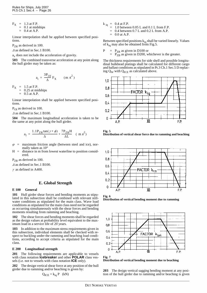
Rules for Ships, July 2007Pt.5 Ch.1 Sec.4 – Page 26
FX = 1.3 at F.P. = 0.1 at midships = 0.4 at A.P.
Linear interpolation shall be applied between specified posi-tions.PZR as derived in 100.Δ as defined in Sec.1 B100.av does not include the acceleration of gravity.503 The combined transverse acceleration at any point alongthe hull girder may be taken as:
FX = 1.5 at F.P. = 0.25 at midships = 0.5 at A.P.
Linear interpolation shall be applied between specified posi-tions.POI as derived in 100.Δ as defined in Sec.1 B100.504 The maximum longitudinal acceleration is taken to bethe same at any point along the hull girder.
ϕ = maximum friction angle (between steel and ice), nor-mally taken as 10°
H = distance in m from lowest waterline to position consid-ered.
PZR as derived in 100.Δ as defined in Sec.1 B100.γ as defined in A400.
E. Global StrengthE 100 General101 Hull girder shear forces and bending moments as stipu-lated in this subsection shall be combined with relevant still-water conditions as stipulated for the main class. Wave loadconditions as stipulated for the main class need not be regardedas occurring simultaneously with the shear forces and bendingmoments resulting from ramming and beaching.102 The shear forces and bending moments shall be regardedas the design values at probability level equivalent to the max-imum load in a service life of 20 years.103 In addition to the maximum stress requirements given inthis subsection, individual elements shall be checked with re-spect to buckling under the ramming and beaching load condi-tions, according to accept criteria as stipulated for the mainclass.
E 200 Longitudinal strength201 The following requirements are applicable to vesselswith class notation Icebreaker and other POLAR class ves-sels (i.e. not to vessels with class notation ICE only).202 The design vertical shear force at any position of the hullgirder due to ramming and/or beaching is given by:
QICE = kiq P (kN)
k iq = 0.4 at F.P. = 1.0 between 0.05 L and 0.1 L from F.P. = 0.4 between 0.7 L and 0.2 L from A.P. = 0.0 at A.P.
Between specified positions kiq shall be varied linearly. Valuesof kiq may also be obtained from Fig.5.
P = PZR as given in D100 or = PZB as given in D200, whichever is the greater.
The thickness requirements for side shell and possible longitu-dinal bulkhead platings shall be calculated for different cargoand ballast conditions as stipulated in Pt.3 Ch.1 Sec.5 D replac-ing QW with QICE as calculated above.
Fig. 5Distribution of vertical shear force due to ramming and beaching
Fig. 6Distribution of vertical bending moment due to ramming
Fig. 7Distribution of vertical bending moment due to beaching
203 The design vertical sagging bending moment at any posi-tion of the hull girder due to ramming and/or beaching is given
at3POI
Δ------------ FX m s2⁄( )=
al1.1PZR γ φ+( )tan
Δ--------------------------------------------
7PZRHΔL
------------------ m s2⁄( )+=
DET NORSKE VERITAS

Rules for Ships, July 2007 Pt.5 Ch.1 Sec.4 – Page 27
by:MICE S = 0.25 kim P L (kNm)
k im = 0.0 at F.P. and A.P. = 1.0 between 0.25 L from F.P. to 0.35 L from A.P. for
ramming load condition = 1.0 between 0.3 L and 0.5 L from F.P. for beaching
load condition.
Between specified positions kim shall be varied linearly. Val-ues of kim may also be obtained from Fig.6 and Fig.7 for ram-ming and beaching load conditions respectively.
P = P ZR or PZB as given in D100 or D200 for ramming andbeaching load conditions respectively.
L as defined in Sec.1 B100.204 The design vertical hogging bending moment at any po-sition of the hull girder due to vibration following the initialramming is given by:
MICE H = 0.6 MICE SR (kNm)
MICE SR = as given in 203 for ramming load condition.
205 The section modulus requirement about the transverseneutral axis is given by:
MS = design stillwater bending moments according toPt.3 Ch.1 Sec.5 B
MICE = design bending moment due to ramming and/orbeaching, see 203 and 204.
The most unfavourable combinations of stillwater and ram-ming/beaching bending moments shall be applied.206 The buckling strength of longitudinal strength membersin bottom, side and deck as well as longitudinal bulkheads sub-ject to compressive and/or shearing loads shall be checked ac-cording to Pt.3 Ch.1 Sec.13.
E 300 Transverse strength amidships301 The line loads specified in D300 shall be applied at dif-ferent water levels including UIWL and LIWL as found neces-sary depending on the structural arrangement of the vessel.302 The line loads shall be applied over one full hold/tanklength or as found necessary to assess the structural strength oftransverse bulkheads and decks supporting the ice reinforcedregions.303 The calculations of transverse strength amidships shallbe based on the most severe realistic combination of ice com-pression loads and static load conditions.304 Recognised structural idealisation and calculation meth-ods shall be applied. Effects to be considered are indicated inPt.3 Ch.1 Sec.12 D200.305 The calculated stresses shall not exceed allowablestresses as stipulated in Pt.3 Ch.1 Sec.12 B400.
E 400 Overall strength of substructure in the foreship401 The total impact forces as stipulated in D100 may havea decisive effect on primary structural systems in the foreship.The loads are assumed to be evenly distributed in such a man-ner that local pressures will not exceed those stipulated for lo-cal members directly exposed to the load as given in D402.402 The design ramming load (not applicable to vessels withclass notation ICE only) taken as
PZR/cosγshall be applied with its center on the stem line at the water line
forward. The most unfavourable design draught forward shallbe assumed with regard to positioning of the load.403 The design bow side impact load taken as POI should bepositioned at various positions within bow side area consid-ered critical for the overall strength of the substructure.Such parts of the bow side area which are aft of the border line ofthe flat side need normally not be considered with respect to POI.404 Recognised structural idealisation and calculation meth-ods shall be applied. Effects to be considered are indicated inPt.3 Ch.1 Sec.12 D200.405 The equivalent stress as defined in Pt.3 Ch.1 Sec.12B400 shall not exceed σf. This is normally achieved for girdertype members when the bending stress is not exceeding 0.9σfand the mean shear stress over a web cross-section is not ex-ceeding 0.45σf.
F. Local StrengthF 100 General101 The requirements in this subsection apply to membersthat may be directly exposed to local ice pressure.102 The buckling strength of web plates and face plates ingirders and stringers subject to ice loads shall be checked ac-cording to methods given in Pt.3 Ch.1 Sec.13 or equivalent.103 In curved regions of ice exposed plating, the stiffening isnormally to be in the direction of the maximum curvature.104 Framing in ice reinforced areas are in general to havesymmetrical cross-section with the web to the extent possiblepositioned at right angle to the plane of the plate. The bendingefficiency and tripping capacity of frames shall be documentedby calculations according to recognised methods as considerednecessary.105 Ice exposed knuckles are in general to be supported bycarlings or equivalent structures.106 Plate fields adjacent to stem and possible knuckles in theforward shoulder shall be supported so as to be of square shapeor otherwise locally strengthened to equivalent standard.
F 200 Plating201 The thickness of plating exposed to patch load is gener-ally not to be less than:
ka = aspect ratio factor for plate field = 1.1 − 0.25 s/ l, maximum 1.0, minimum 0.85kw = influence factor for narrow strip of load (perpendicu-
lar to s)
= , maximum 1.0
mp = bending moment factor = f(b/s), see Table F1 (taking r as b/s)a = s in general = ho for transversely stiffened panelsho = h, see D400 = s, whichever is the smallerb = s in general = ho for longitudinally stiffened platingpo = basic ice pressure in kN/m2 as calculated in D400tk = corrosion addition as given in B500.
ZMS MICE+
0.7σf----------------------------103 cm3( )=
t 23kas0.75
ho0.25
---------------kwpompσf-------------+ tk (mm)=
1.3 4.2
a s⁄ 1.8+( )2-------------------------------–
DET NORSKE VERITAS

Rules for Ships, July 2007Pt.5 Ch.1 Sec.4 – Page 28
s and l as defined in A400.
F 300 Longitudinal stiffeners301 Stiffeners in the bow-, midship- and stern ice reinforcedareas which are largely parallel to the waterline are defined aslongitudinals.302 The web sectional area of stiffeners in ice reinforced ar-eas shall not be less than:
and the web thickness shall not be less than:
for flanged profiles.
The section modulus shall not be less than:
The stiffener connection area ao as defined in Pt.3 Ch.1 Sec.11C400 shall not be less than:
ho = h, see D400 = s, whichever is smallerhw = height of web in mmpo = basic ice pressure in kN/m2 as calculated in D400τ = 0.45 σfσ = 0.9 σf ts = shell plate thickness in mm.
s, l and σy as defined in A400.
AK = tk hw 10 -2 (cm2)wk = section modulus corrosion factor, see Pt.3 Ch.1 Sec.3
C1004c = factor as given in Table C4 of Pt.3 Ch.1 Sec.11 C400.α = 0.5 for AC ≤ 1.0 = 0.15 for AC > 1.0
AC = as defined in D403β = angle of web with shell plating.
β =
Fig. 8Determination of β-angle
F 400 Other stiffeners401 The web sectional area shall not be less than:
and the web thickness shall not be less than:
for flanged profiles.The section modulus shall not be less than:
For end connections with brackets, section modulus includingbracket shall be at least 1.2 Z. the bracket thickness shall notbe less than tw.The connection area ao as defined in Pt.3 Ch.1 Sec.11 C400shall not be less than:
ks =
= 0.69 minimum
Table F1 Parameters for local strength formulas (general application)
r mp me0.05 27.4 132.30.10 14.25 67.90.15 9.87 46.50.20 7.69 35.80.25 6.40 29.50.30 5.57 25.30.35 4.95 22.30.40 4.50 20.20.45 4.09 18.50.50 3.77 17.20.60 3.31 15.40.70 3.02 14.10.80 2.83 13.40.90 2.72 13.01.00 2.68 12.9
For intermediate values of r the parameters may be obtained by lin-ear interpolation.
AW3.7 l 0.5s–( ) h o
1 α– po
τ β lαsin----------------------------------------------------- AK cm2( )+=
tw 1.5po
σf βsin-----------------⎝ ⎠
⎛ ⎞0.67 hwho
ts------------⎝ ⎠
⎛ ⎞0.33
tk (mm)+=
Z41ho
1 α– l2 α– powkσ βsin
----------------------------------------------- cm3( )=
a010cPτ βsin---------------
6.5 c h01 α– l 0.5s–( )p0
τ β 1.4l( )αsin-------------------------------------------------------- cm2( )= =
tan 1– γtanθsin
-----------⎝ ⎠⎛ ⎞ , γ and θ as shown on Fig.8
SIDESHELL
CENTRE LINE
FRAME
y
y γPLAN VIEW
SIDESHELL
CENTRE LINE
FRAME
yy
yy γPLAN VIEW
CE
NTR
E LIN
E
SIDESHELL θFRAME VIEW (y-y)
CE
NTR
E LIN
E
SIDESHELL θFRAME VIEW (y-y)
AW5.8ks hos( )1 α– l 0.5s–( )po
τ l βsin------------------------------------------------------------------- AK (cm2 )+=
tw 1.5po
σf βsin-----------------⎝ ⎠
⎛ ⎞0.67 hws
ts---------⎝ ⎠
⎛ ⎞0.33
tk (mm)+=
Z520l2 s1 α– powk
meσ hoα βsin
----------------------------------------- cm3( )=
a0
5.8cs1 α– 1 0.1h1
2
l2--------–
⎝ ⎠⎜ ⎟⎛ ⎞
l 0.5s–( )ho1 α– po
τl βsin--------------------------------------------------------------------------------------------------- cm2( )=
1 0.5C1 0.5ho+( )3
l3---------------------------------- 1.5
C1 0.5ho+( )2
l2----------------------------------–+
DET NORSKE VERITAS
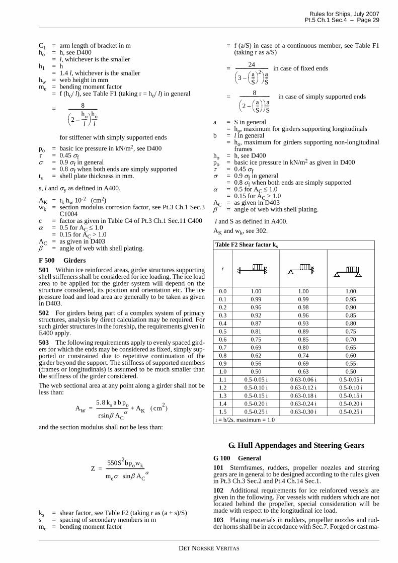
Rules for Ships, July 2007 Pt.5 Ch.1 Sec.4 – Page 29
C1 = arm length of bracket in mho = h, see D400 = l, whichever is the smallerh1 = h = 1.4 l, whichever is the smallerhw = web height in mmme = bending moment factor = f (ho/ l), see Table F1 (taking r = ho/ l) in general
=
for stiffener with simply supported ends
po = basic ice pressure in kN/m2, see D400τ = 0.45 σfσ = 0.9 σf in general = 0.8 σf when both ends are simply supportedts = shell plate thickness in mm.
s, l and σy as defined in A400.
AK = tk hw 10-2 (cm2)wk = section modulus corrosion factor, see Pt.3 Ch.1 Sec.3
C1004c = factor as given in Table C4 of Pt.3 Ch.1 Sec.11 C400α = 0.5 for AC ≤ 1.0 = 0.15 for AC > 1.0AC = as given in D403β = angle of web with shell plating.
F 500 Girders 501 Within ice reinforced areas, girder structures supportingshell stiffeners shall be considered for ice loading. The ice loadarea to be applied for the girder system will depend on thestructure considered, its position and orientation etc. The icepressure load and load area are generally to be taken as givenin D403.502 For girders being part of a complex system of primarystructures, analysis by direct calculation may be required. Forsuch girder structures in the foreship, the requirements given inE400 apply.503 The following requirements apply to evenly spaced gird-ers for which the ends may be considered as fixed, simply sup-ported or constrained due to repetitive continuation of thegirder beyond the support. The stiffness of supported members(frames or longitudinals) is assumed to be much smaller thanthe stiffness of the girder considered.The web sectional area at any point along a girder shall not beless than:
and the section modulus shall not be less than:
ks = shear factor, see Table F2 (taking r as (a + s)/S)s = spacing of secondary members in mme = bending moment factor
= f (a/S) in case of a continuous member, see Table F1(taking r as a/S)
= in case of fixed ends
= in case of simply supported ends
a = S in general = ho, maximum for girders supporting longitudinalsb = l in general = ho, maximum for girders supporting non-longitudinal
framesho = h, see D400po = basic ice pressure in kN/m2 as given in D400τ = 0.45 σfσ = 0.9 σf in general = 0.8 σf when both ends are simply supportedα = 0.5 for AC ≤ 1.0 = 0.15 for AC > 1.0AC = as given in D403β = angle of web with shell plating.
l and S as defined in A400.AK and wk, see 302.
G. Hull Appendages and Steering GearsG 100 General101 Sternframes, rudders, propeller nozzles and steeringgears are in general to be designed according to the rules givenin Pt.3 Ch.3 Sec.2 and Pt.4 Ch.14 Sec.1.102 Additional requirements for ice reinforced vessels aregiven in the following. For vessels with rudders which are notlocated behind the propeller, special consideration will bemade with respect to the longitudinal ice load.103 Plating materials in rudders, propeller nozzles and rud-der horns shall be in accordance with Sec.7. Forged or cast ma-
8
2hol
-----–⎝ ⎠⎛ ⎞ ho
l-----
--------------------------
AW5.8 ks a b po
τ β ACαsin
----------------------------- AK cm2( )+=
Z550S2bpowk
meσ β ACαsin
----------------------------------- =
Table F2 Shear factor ks
r
0.0 1.00 1.00 1.000.1 0.99 0.99 0.950.2 0.96 0.98 0.900.3 0.92 0.96 0.850.4 0.87 0.93 0.800.5 0.81 0.89 0.750.6 0.75 0.85 0.700.7 0.69 0.80 0.650.8 0.62 0.74 0.600.9 0.56 0.69 0.551.0 0.50 0.63 0.501.1 0.5-0.05 i 0.63-0.06 i 0.5-0.05 i1.2 0.5-0.10 i 0.63-0.12 i 0.5-0.10 i1.3 0.5-0.15 i 0.63-0.18 i 0.5-0.15 i1.4 0.5-0.20 i 0.63-0.24 i 0.5-0.20 i1.5 0.5-0.25 i 0.63-0.30 i 0.5-0.25 i
i = b/2s. maximum = 1.0
24
3 aS---⎝ ⎠
⎛ ⎞–2
⎝ ⎠⎛ ⎞ a
S---
------------------------------
8
2 aS---⎝ ⎠
⎛ ⎞–⎝ ⎠⎛ ⎞ a
S---
---------------------------
DET NORSKE VERITAS

Rules for Ships, July 2007Pt.5 Ch.1 Sec.4 – Page 30
terials in structural members subject to lower designtemperatures than –10°C according to B100 shall be impacttested at 5°C below (colder than) design temperature.104 The rudder stock and upper edge of the rudder shall beeffectively protected against ice pressure.105 Aft of the rudder an ice horn with depth minimum = 0.8hice or an equivalent arrangement shall be arranged.106 Exposed seals for rudder stock are assumed to be de-signed for the given environmental conditions such as:
— ice formation— specified design temperature.
G 200 Ice loads on rudders201 An ice load area is defined on the rudder with a lengthequal to the length of the rudder profile lr and height equal tothe effective ice load height (h). The general design rudderforce (FR) is given by the following formula:
FR = 0.2 (h lr)0.85 K po (kN)
K =
z = distance from rudder bottom to centre of the assumedice load area in m
zbl = distance from rudder bottom to the ballast waterline inm
L = as defined in Sec.1 B100po = as given in D400.The rudder force FR gives rise to a rudder torque (MTR) and abending moment in the rudder stock (MB), which both willvary depending on the position of the assumed ice load area,and on the rudder type and arrangement used.In general the load giving the most severe combination of FR,MTR and MB with respect to the structure under considerationshall be applied in a direct calculation of the rudder structure.The design value of MTR is given by:
M TR = FR (0.6 l r − XF) (kNm) = 0.15 FR l r minimumXF = longitudinal distance in m from the leading edge of
the rudder to the centre line of the rudder stock.In lieu of direct calculation design values of MB and FR, appli-cable for the rudder stock diameter at the lower end, may nor-mally be taken as:
Spade rudders: FR = 0.2 (h l r)0.85 po (kN)
MB = FR HB (kNm) Semi spade rudders:
FR = 0.2 ( h l r)0.85 po (kN)MB = 0.5 FR HP (kNm)
Balanced rudders:
MB = 0.25 FR HH (kNm)
HB = distance (m) from lower end of rudder to middle ofneck bearing
HP = distance (m) from lower end of rudder to middle ofpintle bearing
HH = distance (m) from centre of heel bearing to centre ofneck bearing
h = as given in D403.
202 An additional ice load area is defined on the uppermostpart of the rudder including ice knife with a length equal to therudder (including ice knife) (lr) and height below the hull equalto the nominal ice height (hice). This gives rise to a force (F)given by:
F = k p hice l r (kN)
p = design ice pressure in kN/m2 in stern area as given inD400
k = 0.7 in general = 1.0 for vessels with class notations POLAR or Ice-
breaker.
The force F shall be divided between rudder and ice knife ac-cording to their support position. The force acting on the iceknife may generally be taken as:
X = distance from leading edge of rudder to point of attackof the force F
= 0.5 l r (m) minimum = 0.67 l r (m) maximumXK = distance in m from leading edge of rudder to centre of
ice knife.
G 300 Rudder scantlings301 The scantlings of rudders, rudder stocks and shafts, pin-tles, rudder horns and rudder actuators shall be calculated fromthe formulae given in Pt.3 Ch.3 Sec.2, inserting the ruddertorque MTR, bending moments MB and rudder force FR as giv-en in 201, all multiplied by factor 0.7.302 Provided an effective torque relief arrangement is in-stalled for the steering gear, and provided effective ice stop-pers are fitted, the design rudder torque need not be takengreater than:
M TR = MTRO
MTRO = steering gear relief torque in kNm.
303 For rudder plating the ice load thickness shall be calcu-lated as given in F200 using the basic ice pressure as given forthe stern area reduced linearly to half value at the lower end ofthe rudder.304 Scantlings of rudder, rudder stock, rudder horn, rudderstoppers and ice knife as applicable are also to be calculated forthe rudder force given in 202 acting on the rudder and iceknife, with respect to bending and shear. Allowable stresses asgiven in F400.
G 400 Ice loads on propeller nozzles401 A transverse ice load area positioned at the level of thenozzle center is defined on the nozzle with a length equal to thenozzle length and a height equal to the ice load height h given by:
h = 0.8 hice in general = 0.6 hice for nozzle directly inside of protecting struc-
tures, e.g. other nozzle or propeller.
402 The following two alternative longitudinal ice load areasshall be considered:
— an area positioned at the lower edge of the nozzle with awidth equal to 0.65 D and a height equal to the height ofthe nozzle profile
— an area on both sides of the nozzle at the propeller shaftlevel, with a transverse width equal to the height of thenozzle profile and with a height equal to 0.35 D. Bothsymmetric and asymmetric loading shall be checked.
1 zzbl 0.01 L–-----------------------------+
FR 0.2 hlr( )0.85 1HB
2zbl 0.02L–-------------------------------+⎝ ⎠
⎛ ⎞ po (kN)=
FKF X XF–( )XK XF–( )
--------------------------=
DET NORSKE VERITAS

Rules for Ships, July 2007 Pt.5 Ch.1 Sec.4 – Page 31
D = nozzle diameter.403 The design ice pressure p (in kN/m2) for the stern areaas given in D400 shall be assumed for the ice load areas spec-ified under 401 and 402 giving rise to a force (F) given by:
F = k p A (kN)
A = ice load area as defined in 401 and 402k = 0.7 in general = 1.0 for vessels with class notations POLAR or Ice-
breaker.
G 500 Propeller nozzle scantlings501 The scantlings of the propeller nozzle and its supports inthe hull shall be calculated for the ice loads given in 400, withstresses not exceeding allowable values given in F400. Fornozzle plating the ice load thickness shall be taken as given inF200 using the design ice pressure as given for the stern area.
G 600 Steering gear601 The main steering gear shall be capable of putting therudder over from 35° on one side to 30° on the other side in 20seconds, when the vessel is running ahead at maximum servicespeed (corresponding to MCR) and at deepest ice draught.602 For the additional class notation Icebreaker the abovetime shall not exceed 15 seconds.603 The effective holding torque of the rudder actuator, atsafety valve set pressure, shall be capable of holding the rudderin the preset position, when backing in ice, unless arranged inaccordance with 302 and 604.The holding torque means the rudder torque the actuator is ca-pable to withstand before the safety valve discharges.The holding torque need normally not exceed the values givenin Table G1.
MTR = as given in 201.604 The torque relief arrangement, when installed, shall pro-vide protection against excessive rudder ice peak torque, e.g.when backing towards ice ridges.The arrangement shall be such that steering capability is eithermaintained or speedily regained after activation of such ar-rangement.605 All hydraulic rudder actuators shall be protected bymeans of relief valves. Discharge capacity at set pressure shallnot be less than given in Table G2.
606 Where practicable rudder stoppers working on the rud-der blade or head shall be fitted.
G 700 Podded propulsors and azimuth thrusters701 Vessels operating in ice and equipped with podded pro-pulsors or azimuth thrusters shall be designed according to op-erational mode and purpose stated in the design specification.If not given, it shall be assumed that the vessel will be intendedfor continuous operation astern. This information shall also bestated in the ship's papers.702 Ramming astern is not anticipated.703 The structure (housings, struts, bearings etc) of the pod/
thruster shall be dimensioned for basic ice pressures as givenin D400 for stern area in accordance with requested class nota-tion and the operational mode.704 Documentation of both local and global strength capac-ity of the pod and or thruster shall be submitted for class as-sessment. Recognised structural idealisation and calculationmethods shall be applied.705 The equivalent stress as defined in Pt.3 Ch.1 Sec.12B400 shall not exceed σy. This is normally achieved for girdertype members when the bending stress is not exceeding 0.9σyand the mean shear stress over a web cross-section is not ex-ceeding 0.45σy
H. WeldingH 100 General101 The requirements in this subsection apply to membersthat may be directly exposed to local ice pressure and supportstructures for these. Otherwise weld dimensions shall be in ac-cordance with the rules for main class.
H 200 External welding201 The welding of ice strengthened external plating to stiff-eners and to webs and bulkheads fitted in lieu of stiffeners is inany case to have a double continuous weld with throat thick-ness which is not less than:
Where σfw = yield strength in N/mm2 of weld deposit. See Pt.3Ch.1 Sec.11 and Pt.3 Ch.2 Sec.11.Need not be greater than:
= 0.45 x plate thickness for mild steel, and = 0.50 x plate thickness for high strength steel.
If the welding method leads to deeper penetration than normal,the additional penetration can be included in the throat thick-ness.Weld throat shall in no case be less than for main class require-ments.
H 300 Fillet welds and penetration welds subject to high stresses301 In structural parts where high tensile stresses due to localice load act through an intermediate plate, the throat thicknessof double continuous welds shall not be less than given by Pt.3Ch.1 Sec.11 C202, with σ = 0.77 σi.
σi = calculated maximum tensile stress in abutting plate dueto ice load in N/mm2.
302 Where high shear stresses in web plates due to local iceload, double continuous boundary fillet welds shall have throatthickness not less than given by Pt.3 Ch.1 Sec.11 C302 with τ = 0.77 τi.
τi = calculated maximum shear stress due to ice load in N/mm2.
I. Machinery SystemsI 100 Pneumatic starting arrangement101 In addition to the requirements given in Pt.4 Ch.6 Sec.5for a vessel having a propulsion engine(s), which has to be re-versed for going astern, the compressors shall have the capac-ity to charge the receivers in half an hour.
Table G1 Values of holding torqueICE-05 to -15 POLAR-10 to -30 Icebreaker
0.5 MTR 0.75 MTR MTR
Table G2 Relief valve discharge capacityICE-05 to -15 POLAR-10 to
-30Icebreaker
Rudder speed (degrees/s)
4.5 5 6.5
t0.55 s po
σfw------------------------- 0.5tk (mm)+=
DET NORSKE VERITAS

Rules for Ships, July 2007Pt.5 Ch.1 Sec.4 – Page 32
I 200 Sea inlets and discharges201 The sea cooling water inlet and discharge for main andauxiliary engines shall be so arranged that blockage of strumsand strainers by ice is prevented.In addition, the requirements in Pt.4 Ch.6 Sec.5 B302 andB303 shall be complied with.202 At least one of the sea chests shall be sufficiently high toallow ice to accumulate above the pump suctions and coolingwater tank inlet, arranged as follows:
1) The sea inlet shall be situated near the centre line of theship and well aft if possible. The inlet grids shall be spe-cially strengthened.
2) As a guidance for design the volume of the chest shall beabout one cubic metre for every 750 kW engine output ofthe ship including the output of the auxiliary engines nec-essary for the ship's service.
3) To allow for ice accumulation above the pump suction theheight of the sea chest shall not be less than:
Vs =volume of sea chest according to item 2.The suction pipe inlet shall be located not higher thanhmin/3 from top of sea chest.
4) The area of the strum holes shall be not less than four (4)times the inlet pipe sectional area.
Heating coils may be installed in the upper part of the chests.203 A full capacity discharge branched off from the coolingwater overboard discharge line shall be connected to the seachests. At least one of the fire pumps shall be connected to thissea chest or to another sea chest with de-icing arrangement.
I 300 Sea cooling water arrangements301 The sea cooling water inlets and discharges for main andauxiliary engines shall be connected to a cooling water doublebottom tank having direct supply from the sea chests. Thecross-sectional area of the supply line between each sea chestand the cooling water tank shall be twice that of all pump suc-tions connected to the tank.302 Vessels with the class notation Icebreaker or POLARshall comply with 303 to 307.303 The cooling water tank volume in m3 shall be at least0.01 times the output in kW of the main and auxiliary engines.304 The sea water suction line strainers required in Pt.4 Ch.6Sec.5 shall be arranged outstream from the cooling water tank.305 The sea water cooling pumps shall be of the self-primingtype or connected to a central priming system.306 The sea water cooling and ballast piping shall be ar-ranged so that water in the cooling water tank can be circulatedthrough the ballast tanks for the purpose of spare cooling ca-pacity in the case of blocked sea chests.307 Arrangements providing additional cooling capacityequivalent to that specified in 301 through 306 may be consid-ered.
I 400 Ballast system401 Arrangement to prevent freezing shall be provided forballast tanks where found necessary.
Guidance note:Double bottom tanks are normally not required to be providedwith arrangement to prevent freezing.
---e-n-d---of---G-u-i-d-a-n-c-e---n-o-t-e---
J. Propulsion Machinery and PropellersJ 100 General101 Special cold climate environmental conditions shall betaken into consideration in machinery design.102 Propellers and propeller parts (defined in Pt.4 Ch.5 Sec.1A103) shall be of steel or bronze as specified in Pt.2 Ch.2. Nod-ular cast iron of Grade NV 1 and NV 2 may be used for relevantparts in CP-mechanism. Other type of nodular cast iron withelongation ≥ 12% may be accepted upon special considerationfor same purposes. Propeller shafts are subject to CharpyV-notch impact testing at minus 10°C and the average energyvalue shall be minimum 27 J.103 Grey cast iron is normally not accepted for componentssubject to ice shocks, as e.g. thrust bearing housings.104 Shafting systems equipped with specially designed me-chanical torque limiting devices are subject to special consid-eration. Such devices, when accepted, shall comply withredundancy type R2 in Pt.4 Ch.1 Sec.1 B108.The torque limit is normally not less than 1.5 KA TO.For KA and TO, see 500.105 Ice induced vibrations (repetitive ice chocks) in theshafting system shall be considered.Forced torsional vibration calculations shall include an evalu-ation of transient vibrations excited by ice on the propeller.106 For non-reversible machinery plants, special meansshall be provided for reversing the propellers stuck in ice.107 The propulsion line shall be designed such that the bladefailure load Fice given in 404 shall not cause damage in theblade bolt connection, propeller hub, pitch mechanism, shaftconnection, propeller shaft and thrust bearing.
Guidance note:Damage, in this context, means when the stresses in the highestloaded part of the considered cross section reaches yield stress.The local effect of stress raisers may be ignored.Blade failure load (Fice) is the load causing plastic bending of thepropeller blade in a section just outside the root fillet.
---e-n-d---of---G-u-i-d-a-n-c-e---n-o-t-e---
J 200 Engine output201 The maximum continuous output of propulsion machin-ery shall not be less than:P = 1.5 cs cp I N B [1 + 1.6 T + 27 (0.1 I N / T0.25)0.5] (kW)
cs = 1.0 for vessels with conventional «icebreaker stem» = 0.9 + γ / 200; minimum 1.0, but need not exceed 1.2cp = 1.0 for controllable pitch propeller = 1.1 for fixed pitch propellerIN = ice class number (figure added to class notation)B = moulded breadth at waterline (m), local increase in
way of stem area is normally not to be taken into ac-count
T = rule draught (m)γ = stem angle (see Fig.1).
202 When the vessel is provided with special means whichwill improve her performance in ice (e.g. air bubbling system),the input rating of machinery used for such purpose may beadded to the actual rating of propulsion machinery.The propeller rating is, however, not to be less than 85% of thatrequired in 201.203 When the vessel is provided with a nozzle of efficientdesign, a reduction of required engine output corresponding toincrease of thrust in ice conditions will be considered. The re-duction is, however, not to exceed 20% of required output in201 and 202.
hmin 1.5 Vs3≥
DET NORSKE VERITAS

Rules for Ships, July 2007 Pt.5 Ch.1 Sec.4 – Page 33
204 Additional reduction of the required output may be con-sidered for a vessel having design features improving her per-formance in ice conditions. Such features shall be documented,either by means of model tests or full scale measurements.It is understood that such approval can be revoked, if experi-ence motivates it.
J 300 Determination of ice torque and loads301 Ice torque (TICE), used for determination of scantlings inpropellers and shafting systems, shall be taken as follows:
TICE = m D2 (kNm) The factor m is given in Table J1 as function of ice class:
D = propeller diameter in m.302 For propellers running in nozzles of satisfactory design,the ice torque will be considered based on submitted documen-tation, e.g. measurements carried out on similar vessels.However, if nothing else is documented, the following may beused:
TICE = (0.9 - 0.01 m D-0.5) m D2 (kNm) Large fragments of ice shall not have free access into or to-wards the front of the nozzle.303 Axial loads in shaftline:F = TH + 1.5 FLE (axial load, ahead)F = 0.8 TH + FLE (axial load, astern)The axial load F shall be applied on the propeller side of thethrust bearing.TH and FLE according to 400 and 500.
J 400 Propeller401 The blade scantling requirements given in Sec.3 apply,except as given below. In calculations involving the ice torque,TICE according to 300 shall be applied.Propeller blade scantlings of martensitic — austenitic and fer-ritic — martensitic stainless steel may be specially considered.402 Arrangement of propellers in ice classes ICE-15 andPOLAR-10 to -30 shall be such that large fragments of ice donot have free access into the front of the propeller disc within0.7 radius.403 When the outer sections of the propeller blade is not sub-ject to special consideration according to Sec.3 J303, the bladetip thickness at the radius 0.95 R shall not be less than:
D and σb as given in 404.σb shall not be taken higher than 2.5 σy.For propellers running in nozzles blade tip thickness smallerthan above may be accepted. The tip thickness, however, shallnot be less than 3/4 of the above value.The thickness of the blade edge and the propeller tip shall notbe less than 50% of minimum t as given above, measured at1.25 t from the edge or tip, respectively. For propellers wherethe direction of rotation is not reversible, this requirement onlyapplies to the leading edge and propeller tip.
404 The fitting of the propeller blades and the pitch controlmechanism shall withstand a design static load not less than:
This load shall be applied on the blade at a radius 0.9 R and atan offset from blade centre axis of CTE or 2/3CLE, whicheveris the greater.
σn = 0.37 σb + 0.6 σyσb = ultimate tensile strength of the blade (N/mm2)σy = the blade yield stress or 0.2% offset point (N/mm2)cr = the length of the blade section at RR radius (mm)tr = the corresponding thickness (mm)D = propeller diameter (m)R = D/2 (m)RR = radius to a blade section taken at the termination of the
blade root fillet (rounded upwards to the nearest R/20),ref. cr and tr (m)
CTE = distance from axis of rotation of the blade to the trail-ing edge, measured along the cylindrical section at0.9R
CLE = distance from axis of rotation of the blade to the lead-ing edge, measured along the cylindrical section at0.9R.
405 Propeller blade bolts shall have a section modulus, re-ferred to an axis tangential to the bolt pitch diameter, not lessthan:
S = 1.0 for CP-propellers = 1.25 for FP-propellersσy = yield stress of bolt material (N/mm2)RB = radius to bolt plan (m).
cr, tr and σn as given in 404.The bolts shall have a design which minimises stress concen-trations in transition zones to threads and bolt head as well asin way of the threads, and reduces risk for plastic deformationsin the threads.406 For all parts in the pitch control mechanism, which aresubject to variable ice loads, stress concentration shall be takeninto consideration.407 The blade fitting and other parts in the pitch controlmechanism shall be designed to withstand all forces producedby the pitch control system at its maximum power. The forcesshall be assumed to act towards one blade at a time.
Table J1 Values of mIce class m Icebreaker mICE-05 16 ICE-05 21ICE-10 21 ICE-10 30ICE-15 27 ICE-15 30POLAR 33 POLAR 40
t m 2D+( ) 490σb--------- (mm)=
FICE 0.3σncrtr
2
D 0.9 RR R⁄–[ ]---------------------------------------10 6– (kN)=
0.9RLE2/3CTE 2/3C
WBS 0= .15 S cr tr2 σn
σy------
0.9 RB R⁄–0.9 RR R⁄–----------------------------- mm3( )
DET NORSKE VERITAS

Rules for Ships, July 2007Pt.5 Ch.1 Sec.4 – Page 34
Guidance note:The pitch control mechanism shall be designed for the followingdynamic ice loads:
applied at the 0.9 radius perpendicular to the blade plane at therespective blade edges.Number of load cycles to be considered shall not be taken lessthan one million for ice classes ICE-05 to -15 and infinitive forPOLAR-10 to -30 and class notation Icebreaker. The designpressure of the hydraulic system shall not be taken less than twicethe pressure needed to produce the blade spindle torque based onthe above forces. The forces are assumed to act on one blade at atime only.
---e-n-d---of---G-u-i-d-a-n-c-e---n-o-t-e---
408 Fitting of the propeller to the shaft is given in Pt.4 Ch.4Sec.1 as follows:
— Flanged connection in B300 — Keyless cone connection in B400— Keyed cone connection in B500
(Considering 0°C sea water temperature)If the propeller is bolted to the propeller shaft, the bolt connec-tion shall have at least the same bending strength as the propel-ler shaft.
J 500 Propulsion shaft line reinforcement501 Determination of factors for ice reinforcement of shaftline.
TO = torque (kNm) in the actual componentTICE = ice torque (kNm) according to 300u = gear ratio (if no reduction gear, or for components
on the propeller side of a reduction gear use u = 1)I = equivalent mass moment of inertia in kgm2 based
on torque of all parts on engine side of componentunder consideration.
Masses rotating with engine speed to be transformed accordingto:
Iequiv = I actual u2
In propulsion systems with hydraulic coupling, torque convert-er or electromagnetic slip coupling, the masses in front of thecoupling shall not be taken into consideration
It = equivalent mass moment of inertia of propulsion sys-tem in kgm2. (Masses in front of hydraulic or electro-magnetic slip coupling shall not be taken intoconsideration.)
502 Application factor for diesel and or turbine machinery ingeneral:
503 Application factor for electric motor machinery or dieselmachinery with hydrodynamic torque converter:
1) Diesel engine with torque converter or hydrodynamic cou-pling:
TTC max = maximum possible transmittable torque throughconverter/coupling.
2) Electric motor drive:
Tmax = motor peak torque (steady state condition).Alternatively to the above criteria, the ice impact load may bedocumented by simulation of the transient dynamic responsein the time domain. For branched systems, such simulation isin general recommended.504 Regarding shaft connections, use KAice in Pt.4 Ch.4Sec.1 as follows:
— Flange connections, see B300— Shrink fit connections, see B400— Keyed connections, see B500
505 The diameter of the propeller shaft in way of aft bearingand at least a length 2.5 times the required diameter forward ofpropeller flange or hub, shall not be less than:
cr t2 = actual value of blade section considered at the termina-tion of the blade root fillet (rounded upwards to nearest1/20 of R).
σy refers to the shaft material.σn refers to the blade material, see 404.cr and t as given in 404.The propeller shaft diameter may be evenly tapered to 1.15times the required intermediate shaft diameter between the aftbearing and the second aft bearing. Forward of this bearing thepropeller shaft diameter may be reduced to 1.05 times the re-quired diameter of the intermediate shaft (using material factorvalid for propeller shaft).The propeller shaft flange thickness (propeller fitting) shall beat least 0.3 times the actual shaft diameter. The fillet radiusshall be at least 0.125 times the actual shaft diameter.506 The diameter of intermediate shafts shall be determinedbased on methods given in Pt.4 Ch.4 Sec.1 B201.
a) When using the classification note 41.4 the necessary re-inforcement is determined by using KAice in the given cri-teria.
b) With KAice ≤ 1.4 the method in Pt.4 Ch.4 Sec.1 B206 maybe used, i.e. no ice reinforcement beyond 1A1 rules.
c) When using the method in Pt.4 Ch.4 Sec.1 B208, the min-imum diameter in item 3 of that paragraph shall be multi-plied with:
but not less than 1.0In item 4 of same paragraph, the vibratory torsional stressτv is replaced by:
and shall not exceed τC.507 Support and construction of the thrust bearing shall bedesigned to avoid excessive axial shaft movements caused byheavy axial forces when the propeller hits ice.The thrust bearing shall have static strength designed for notless than the nominal thrust plus the static ice force as definedin 404. The ice force is assumed to act in the axial direction.
FLE = TICE / 0.9 R (kN) at leading edge,F TE = - 0.5 FLE at trailing edge,
T0
iceAice IuT
IT1K +=
t0
ice
0
maxTCAice IuT
ITT
TK +=
T0
ice
0
maxAice IuT
ITT
TK +=
dp 1.160.9σncrt
2
0.9 RR R⁄( )–[ ]σy---------------------------------------------
⎝ ⎠⎜ ⎟⎛ ⎞
13---
(mm)=
31
Aice4.1
K⎟⎟⎠
⎞⎜⎜⎝
⎛
( ) 0Aicev T1K5.0 ⋅−⋅=τ
DET NORSKE VERITAS

Rules for Ships, July 2007 Pt.5 Ch.1 Sec.4 – Page 35
Both forward and astern directions shall be considered.The basic static load ratings of roller bearings shall not be lessthan 2 times the load.For calculation of the bearing pressures in the ice conditions,the following thrust force applies:
THI = 1.1 TH + 0.25 FLE ± 0.75 FLE (kN)
FLE = according to 407TH = mean «bollard thrust» of the propeller or 1.25 times the
mean thrust at maximum continuous ahead speed, in kN.
Calculated lifetime (B10) of roller bearings shall be minimum40 000 h, by applying the load THI.508 For reduction gears, use KAice in Pt.4 Ch.4 Sec.2.Axial ice load according to 507, when applicable, shall be con-sidered with respect to bearing arrangement and stiffness of thegear housing.509 For clutches, use KAice in Pt.4 Ch.4 Sec.3 B100.510 For torsional elastic coupling, use KAice in Pt.4 Ch.4Sec.5 B200.
K. ThrustersK 100 General101 Special cold climate environmental conditions shall betaken into consideration in the thruster design.102 Means for heating and circulation of lubrication and hy-draulic oil shall be provided.
K 200 Propulsion thrusters201 Thrusters, which are used for propulsion purpose, shallcomply with the relevant requirements in J.
Guidance note:Any thruster intended to be used for propulsion in ice, not onlythe main propulsion thrusters, is defined as propulsion thrustersin this context.
---e-n-d---of---G-u-i-d-a-n-c-e---n-o-t-e---
202 Steering gear for azimuth thrusters shall be designed towithstand all relevant ice loads. Both ice loads on propellernozzle (G400) and on propeller blade (J400) shall be consid-ered.
K 300 Other thrusters301 For shafting the following applies:
— Maximum peak torque, which may occur due to ice in thepropeller, shall be taken into consideration.
— The load F in 303 shall be considered for the propeller shaft.
Maximum permissible equivalent stress is 80% of the yieldstress or 0.2% proof stress of materials.302 For reduction gears the application factor (KA) shall betaken as minimum 1.2.303 The propeller blade shall be designed to withstand apeak load, without exceeding 80% of blade material yield or0.2% proof stress of:
T = maximum peak torque of prime mover (kNm)α0.85 = pitch angle at radius 0.85 RR = propeller radius (m).The load F is assumed to apply at 0.85 R, perpendicular to theblade plane.
L. Stability and Watertight Integrity L 100 Application101 Vessels with class notation Icebreaker or POLARshall comply with the requirements of Pt.3 Ch.3 Sec.9 as wellas the requirements of this subsection.
Guidance note:The requirements contained in this section are based on the IMOMSC/Circ.1056 "Guidelines for Ships Operating in Arctic Ice-covered waters" as applicable for polar classes 1 to 3.
---e-n-d---of---G-u-i-d-a-n-c-e---n-o-t-e---
L 200 Documentation201 Documentation for approval
— preliminary damage stability calculations— final damage stability calculations
(not required in case of approved limit curves, or if ap-proved lightweight data are not less favourable than esti-mated lightweight data).
202 Documentation for information
— internal watertight integrity plan.
203 Details of above documentation are given in Classifica-tion Note No. 20.1.
L 300 Requirements for intact stability301 The initial metacentric height GM shall not be less than0.5 m.302 Account shall be taken of the effect of icing in the stabil-ity calculations.
Guidance note:The realistic figures for thickness and density of the accumulatedice load may vary with different areas. In lack of detailed infor-mation the following ice loads should be accounted for:- 30 kg per square metre on exposed weather decks and gang-
ways- 7.5 kg per square metre for projected lateral area of each side
of the vessel above the water plane- the weight distribution of ice on discontinuous structures such
as railings, rigging, posts and equipment shall be included byincreasing the total area for the projected lateral plane of thevessel's sides by 5%. The static moment of this area shall beincreased by 10%.
---e-n-d---of---G-u-i-d-a-n-c-e---n-o-t-e---
303 Suitable calculations should be carried out and or testsconducted to demonstrate the following:
1) the ship, when operated in ice within approved limitations,during a disturbance causing roll, pitch, heave or heel dueto turning or any other cause, should maintain sufficientpositive stability, and
2) when riding up in ice and remaining momentarily poisedat the lowest stem extremity, should maintain sufficientpositive stability.
304 Sufficient positive stability in paragraphs 303 1) and 2)means that the ship is in a positive state of equilibrium with apositive metacentric height of at least 150 mm, and a line 150mm below the edge of the freeboard deck as defined in the ap-plicable LL-Convention, is not submerged.305 For performing stability calculations on ships that rideup onto the ice, the ship should be assumed to remain momen-tarily poised at the lowest stem or extremity as follows:
— for a regular stem profile, at the point at which the stemcontour is tangent to the keel line
— for a stem fitted with a structurally defined skeg, at the
F T0.85R α0.85sin------------------------------------- (kN)=
DET NORSKE VERITAS

Rules for Ships, July 2007Pt.5 Ch.1 Sec.4 – Page 36
point at which the stem contour meets the top of the skeg— for a stem profile where the skeg is defined by shape alone,
at the point at which the stem contour tangent intersectsthe tangent of the skeg, or
— for a stem profile of novel design, the position should bespecially considered
— the same considerations shall be made for ships designedfor breaking ice at the stern.
L 400 Requirements for damage stability401 The damage assumptions in 402 to 403 and the criteriain 407 and 408 shall be the basis of damage stability calcula-tions.402 The dimensions of an ice damage penetration should betaken as:
— longitudinal extent 0.045 of deepest ice waterline length ifcentred forward of the point of maximum beam on the wa-terline, and 0.015 of waterline length otherwise,
— depth 760 mm measured normal to the shell over the fullextent of the damage, and
— vertical extent the lesser of 0.2 of deepest ice draft, or oflongitudinal extent.
403 The centre of the ice damage may be located at any pointbetween the keel and 1.2 times the deepest ice draft. The verti-cal extent of damage may be assumed to be confined betweenthe keel and 1.2 times the deepest ice draft. 404 If damage of lesser extent than that specified above re-sults in a more severe condition, such lesser extent shall be as-sumed.405 For pipes, ducts or tunnels situated within the assumedextent of damage, see 500.406 The following permeability factors shall be assumed:
407 Damage criteria at the final stage of flooding:
— the final equilibrium waterline after damage shall be be-low the edge of any non-watertight opening
— the final equilibrium heel angle after damage shall not ex-ceed 15°. This may be increased to 17° if the deck edge isnot submerged
— GZ after damage has at least 20° positive range beyondequilibrium
— maximum GZ of at least 0.10 m within 20° beyond themaximum equilibrium position.
408 Damage criteria at the intermediate stages of flooding:
— the waterline after damage shall be below the edge of anynon-weathertight opening
— the heel angle after damage shall not exceed 25°. This maybe increased to 30° if the deck edge is not submerged
— GZ after damage has at least 10° positive range beyondequilibrium
— maximum GZ of at least 0.05 m within 10° beyond themaximum equilibrium position.
409 A maximum allowable VCG curve with respect to dam-age stability shall be included in the stability manual. Other-wise the damage stability approval shall be limited to thepresented loading conditions.
L 500 Requirements to watertight integrity501 As far as practicable, tunnels, ducts or pipes which maycause progressive flooding in case of damage, shall be avoidedin the damage penetration zone. If this is not possible, arrange-ments shall be made to prevent progressive flooding to vol-umes assumed intact. Alternatively, these volumes shall beassumed flooded in the damage stability calculations.502 The scantlings of tunnels, ducts, pipes, doors, staircases,bulkheads and decks, forming watertight boundaries, shall beadequate to withstand pressure heights corresponding to thedeepest equilibrium waterline in damaged condition.
– store rooms: 0.60– machinery spaces: 0.85– tanks and other spaces: 0.95– partially filled ballast tanks: consistent with minimum
tank content.
DET NORSKE VERITAS

Rules for Ships, July 2007 Pt.5 Ch.1 Sec.5 – Page 37
SECTION 5 SEALERS
A. GeneralA 100 Classification101 The requirements in this Section apply to vessels spe-cially built for catching.102 Vessels built in compliance with the following require-ments may be given the class notation Sealer.
A 200 Hull form201 The hull form of the vessel shall be suitable for naviga-tion in pack ice and shall be such that the ship cannot bepressed down by ice. The sides of the hull shall be convex, withthe greatest breadth at the first continuous deck above the de-sign waterline. The angle between the tangent to the ship's sideat the deck and the vertical shall not be less than 5 degrees.
B. Strength of Hull and SuperstructuresB 100 Ship's sides and stem101 The scantlings of shell plating, frames, girders and stemshall at least be as required for ice class ICE–05, see Sec.4.
B 200 Superstructures201 Side plating in superstructures shall have increasedthickness in an area extending not less than 1 m above the up-per ice waterline (UIWL), as defined in Sec.1 B, of the vesselor above deck if the vessel has no freeboard mark. In the men-tioned area the plate thickness forward of 0.25 L from F.P.shall not be less than:
t = 10 + 0.08 L (mm) Aft of 0.25 L from forward perpendicular the plate thicknessshall not be less than:
t = 7.5 + 0.06 L (mm) 202 Frames in superstructures in way of crew accommoda-tion shall have a section modulus at least 50% in excess of therequirement for main class. The frames shall have brackets atboth ends.203 Intermediate frames with section modulus as for frames
according to 202, shall be fitted in way of the strengthened sideplating stated in 201. The top of intermediate frames shall beconnected to a horizontal girder of same depth as the framesand with a flange area not less than 10 cm2. The horizontalgirder shall be attached to all side frames.
C. Sternframe, Rudder and Steering GearC 100 Design rudder force101 The scantlings shall be based on a rudder force 3 timesthe design rudder force for main class.
C 200 Protection of rudder and propeller201 Ice fins shall be fitted for protecting rudder and propeller.
D. Anchoring and Mooring EquipmentD 100 General101 The equipment may be as required for fishing vessels.
E. MachineryE 100 Output of propulsion machinery101 The output shall not be less than 735 kW. If the vesselhas a controllable pitch propeller, the output requirement maybe reduced by 10%.
E 200 Thrust bearing, reduction gear, shafting and pro-peller201 The scantlings are at least to be as required for class no-tation ICE–05, see Sec.4.
E 300 Machinery systems301 For requirements to sea inlets and cooling water system,see Sec.3 J602.
DET NORSKE VERITAS

Rules for Ships, July 2007Pt.5 Ch.1 Sec.6 – Page 38
SECTION 6 WINTERIZATION
A. General
A 100 Classification101 The requirements in this section apply to ships intendedfor service in cold climate environments for longer periods.102 The class notation WINTERIZED (design temp. °C)may be assigned to ships complying with the requirements insubsections B through D.103 The class notation WINTERIZED ARCTIC (designtemp. °C) may be assigned to ships complying with the re-quirements in subsections B through E.
Guidance note:The information within the brackets state the design temperaturein °C.
---e-n-d---of---G-u-i-d-a-n-c-e---n-o-t-e---
Guidance note:The design temperature is defined by the user when signing theclass contract. The design temperature reflects the lowest meandaily average air temperature in the area of operation, and an ex-treme air temperature about 20°C below this may be tolerable tothe structures and equipment from a material point of view. Forcalculations where the most extreme temperature over the day isrelevant, e.g. heat balances in ventilated spaces, the air tempera-ture can be set 20°C lower than the design temperature in the no-tation.
---e-n-d---of---G-u-i-d-a-n-c-e---n-o-t-e---
A 200 Documentation201 Documentation as specified for notations:Documentation as specified for the selected ice class notationin Sec.3 or Sec.4, and for class notation DEICE in Pt.6 Ch.1Sec.5 shall be submitted.202 Additional documentation for WINTERIZED ARCTICas specified for notations CLEAN in Pt.6 Ch.12, OPP-F inPt.6 Ch.1 Sec.6 and RPS in Pt.6 Ch.2 shall be submitted.
B. Ship Design and Arrangement
B 100 Ship arrangement - Ice strengthening of hull, rudder, steering gear, propeller and propeller shaft101 The ship shall be built to an ice class notation accordingto Sec.3 or Sec.4.102 Life boats shall be located in deck-house recesses withprotection from water spray. Free fall lifeboats are not accepted.103 Anchor windlass shall be located inside a deckhouse, orinside a forecastle space.104 The “Emergency towing arrangements” aft on tankersshall be located inside a deckhouse or in an under-deck space.105 The cargo manifold, and manifold valves on tankersshall be located in a semi-enclosed deck house.106 Safe access to the bow shall be arranged via an on-decktrunk or under-deck passageway.107 Navigation bridge wings shall be fully enclosed.108 A heated watchman’s shelter shall be arranged at thegangway.
109 Immersion suits shall be of the insulated type.110 Engine room and other spaces containing importantequipment shall be fitted with heating unless the equipmentand piping installations are so designed and or heated that theycan operate at the lowest indoor temperature that can be gener-ated by the outdoor temperature defined in the notation, withrealistic space ventilation. 111 An ice search light shall be provided on the wheelhousetop.
C. Material for Low TemperatureC 100 Hull material101 Material used in external structures above the lower icewaterline (LIWL), as defined in Sec.1 B, shall be appropriatefor the design temperature given in the class notation. Externalstructure is defined as the plating with stiffening to a distanceof 0.5 meter inwards from the shell plating, exposed decks andsides of superstructure and deckhouses. The requirement alsoapplies to masts.102 Steel grades shall be selected in accordance with Pt.2Ch.2 Sec.1 and as given in the requirements of the DAT(-X°C)(special features notation), in Sec.7 B.
C 200 Materials for equipment201 All equipment exposed to the low temperature and beingimportant for ship operations shall be made from materialssuitable for the design temperature specified in the class nota-tion.
Guidance note:Cranes are outside of class scope and the material requirementsare therefore not considered relevant for cranes.
---e-n-d---of---G-u-i-d-a-n-c-e---n-o-t-e---
202 Equipment for which 201 applies include, but is not lim-ited to:
— windlass and chain stopper— mooring winches and associated equipment— lifeboats and or rescue boat davits and winches— rudderstock with flanges and bolts if flanged connection— cargo oil piping, vents and air pipes— hatches for cargo holds and cargo tanks— strongpoint for emergency towing.
Guidance note:Cables exposed to the low temperature should comply with thelatest revision of CSA standard C22.2 No. 0.3 for impact test at –35°C and bending test at –40°C.
---e-n-d---of---G-u-i-d-a-n-c-e---n-o-t-e---
203 For equipment or parts of equipment fabricated fromplate material, steel grades according to requirements for pri-mary structure (class III) in Sec.7 B, shall be used.204 For equipment or parts of equipment fabricated fromforged or cast material, steel grades according to Pt.2 Ch.2Sec.5 G or Pt.2 Ch.2 Sec.7 F, respectively, shall be used.205 For pipes, steel grades according to Pt.2 Ch.2 Sec.4 Dshall be used.
DET NORSKE VERITAS
Rules for Ships, July 2007 Pt.5 Ch.1 Sec.6 – Page 39
D. Anti-Icing, Anti-Freezing and De-icingD 100 General101 The requirements for class notation DEICE shall becomplied with.102 In addition to 101 the following shall be complied with:
a) anti-icing and or de-icing of mooring equipmentb) de-icing and or anti icing of cranes covered by CRANE-
notationc) de-icing arrangements for anchor chaind) fire main and foam main, if applicable, shall be heat traced
or located inside a heated passagewaye) water pipes on open decks and in non-heated spaces shall
be arranged self-draining or provided with heat tracingf) hydraulic oil systems on open decks and in non-heated
spaces shall be arranged with heating, alternatively specialhydraulic oil for low temperatures shall be used
g) forecastle deck and poop deck shall be provided with un-der-deck heating to ease ice removal
h) horizontal surfaces of superstructure shall be providedwith heating to ease ice removal
i) thermal protection suits including face masks, gloves andboots shall be provided for all crew members.
j) for design temperatures lower than –10°C the followingrequirements also apply:
— ballast tanks and fresh water tanks located partly orfully above ballast water line shall be provided withmeans for heating
— fuel oil storage tanks shall be provided with sufficientheating enabling transfer of fuel
— fuel oil transfer lines exposed to the low temperatureenvironment shall have heat tracing
— where heating of horizontal deck areas and or outdoorpassageways is required in accordance with 101, the
heating capacity shall not be less than 450 W/m2.
E. Additional Requirements for Class Notation WINTERIZED ARCTIC (design temp.)
E 100 Ice strengthening and propulsion101 The ship shall be built to an ice class notation accordingto Sec.4.102 Propellers intended for propulsion shall be of the con-trollable pitch (CP) type, when driven by diesel engines, or ei-ther of controllable pitch (CP) or fixed (FP) type whenelectrically driven, provided that the electrical systems are de-signed to provide 100% of the nominal torque from 100% to20% of the rpm.103 The propeller material shall be made of stainless steel ora material providing equivalent low temperature properties.104 The RPS notation is mandatory.
E 200 Enhanced oil pollution prevention201 The requirements for class notation CLEAN shall becomplied with.202 The requirements for class notation OPP-F shall becomplied with.203 For oil tankers the accidental oil outflow index: OM shallnot exceed 0.01 calculated in accordance with revised MAR-POL Annex I, Reg. 23.204 Cargo oil lines shall be located under deck or inside adeck trunk, except for the loading and unloading manifold.205 Non- toxic and biodegradable oil shall be used for sterntube and CP propeller systems.206 The bunker capacity shall be sufficient for at least 30days operation of the ship’s accommodation power, in additionto what is needed for the transit distance.
DET NORSKE VERITAS

Rules for Ships, July 2007Pt.5 Ch.1 Sec.7 – Page 40
SECTION 7 DAT(-X°C)
A. GeneralA 100 Classification101 The requirements in this section apply to materials inships of any type intended to operate for longer periods in areaswith low air temperatures (i.e. regular service during winter toArctic or Antarctic waters).Vessels built in compliance with the requirements of Sec.7,will be assigned the notation DAT(-XºC), indicating the de-sign temperature applied as basis for approval.
A 200 Documentation201 Specification of design temperature.
A 300 Definitions301 External structure is defined, with respect to design tem-perature, as the plating with stiffening to a inwards distance of0.5 metre from the shell plating, exposed decks and exposedsides and ends of superstructure and deckhouses.302 Temperature terms definitions (see also Fig.1): Design temperature is a reference temperature used as a crite-
rion for the selection of steel grades. The design temperaturefor external structures is defined as the lowest mean daily av-erage air temperature in the area of operation. This temperatureis considered to be comparable with the lowest monthly meantemperature in the area of operation −2°C. If operation is re-stricted to «summer» navigation the lowest monthly meantemperature comparison may only be applied to the warmerhalf of the month in question. The corresponding extreme lowtemperature is generally considered to be 20ºC lower than thedesign temperature.Mean daily average temperature is the statistical mean aver-age temperature for a specific calendar day, based on a numberof years of observations (= MDAT). Monthly mean temperature is the average of the mean dailytemperature for the month in question (= MAMDAT). Lowest mean daily temperature is the lowest value on the an-nual mean daily temperature curve for the area in question. Forseasonally restricted service the lowest value within the time ofoperation applies. Lowest monthly mean temperature is the monthly mean tem-perature for the coldest month of the year.
Fig. 1Commonly used definitions of temperatures
MDHT Mean* daily high (or maximum) temperature MDAT Mean* daily average temperature MDLT Mean* daily low (or minimum) temperature MAMDHT Monthly average** of MDHT MAMDAT Monthly average** of MDAT MAMDLT Monthly average** of MDLT
MEHT Monthly extreme high temperature (ever recorded)
MELT Monthly extreme low temperature (ever recorded).
* Mean: Statistical mean over observation period (at least 20 years). ** Average: Average during one day and night.
DET NORSKE VERITAS

Rules for Ships, July 2007 Pt.5 Ch.1 Sec.7 – Page 41
B. Material SelectionB 100 Structural categories101 Structural strength members or areas are classified in 4different classes for the purpose of selecting required materialgrades. The classes are generally described as follows: Class IV:
— Strakes in the strength deck and shell plating amidships in-tended as crack arrestors.
— Highly stressed elements in way of longitudinal strengthmember discontinuities.
Class III:
— Plating chiefly contributing to the longitudinal strength. — Fore ship substructure in vessels with notations ICE-
BREAKER or POLAR.— Aft ship substructures in vessels equipped with podded
propulsors and azimuth thrusters, and intended for contin-uous operation astern.
— Foundations and support structures for heavy machineryand equipment, including crane pedestals.
— Frames for windlasses, emergency towing and chain stopper.
Class II:
— Structures contributing to longitudinal and/or transverse
hull girder strength in general. — Appendages of importance for the main functions of the
vessel. Stern frames, rudder horns, rudder, propeller noz-zles and shaft bracket. (To be class III for vessels with no-tations ICE, ICEBREAKER or POLAR).
— Gutter bars of oil spill coamings attached to hull.— Structures for subdivisions. — Structures for cargo, bunkers and ballast containment. — Internal members (stiffeners, girders) on plating exposed
to external low temperatures where class III and IV is re-quired.
Class I:
— Local members in general unless upgraded due to specialconsiderations of loading rate, level and type of stress,stress concentrations and load transfer points and/or con-sequences of failure.
— Deckhouse structure not exposed to longitudinal stresses.— Cargo hatch covers.
102 The material class requirement may be reduced by oneclass for:
— laterally loaded plating having a thickness exceeding 1.25times the requirement according to design formulas,
— laterally loaded stiffeners and girders having section mod-ulus exceeding 1.5 times the requirement according to de-sign formulas.
B 200 Selection of steel grades201 Plating materials for various structural categories as de-fined in 100 of exposed members above the ballast waterlineof vessels with class notation DAT (-XºC) shall not be of lowergrades than obtained from Fig.2 using the specified designtemperature.
Plating materials of non-exposed members shall not be of low-er grade than obtained according to Pt.3 Ch.1 Sec.2 Table B1and or Pt.3 Ch.2 Sec.2 Table B1.Cranes shall fulfil requirements in accordance with “Rules forCertification of Lifting Appliances”.
Table B1 Classification of longitudinal and transverse strength members, plating
Structural member Within 0.4L amidships(Within 0.2 L aft of amidships and 0.3 L forward of amidships in vessels with notation ICEBREAKER or POLAR)
Elsewhere
Deck plating exposed to weather, in general.Side plating.Longitudinal bulkhead plating, in general.Transverse bulkhead plating.
II II
Bottom plating including keel plate. Strength deck plating. 2) Continuous longitudinal members above strength deck excluding longitudinal hatch coamings.Upper strake in longitudinal bulkhead.Upper strake in top wing tank.
III 5) II
Sheer strake at strength deck.6)Stringer plate in strength6) deck.Deck strake at longitudinal bulkhead 1) Bilge strake 3) Continuous longitudinal hatch coamings7)
IV III 4)
1) In ships with breadth exceeding 70 m at least three deck strakes shall be class IV amidships. 2) Plating at corners of large hatch openings shall be specially considered. Class IV shall be applied in positions where high local stresses
may occur. 3) May be of class III amidships in ships with a double bottom over the full breadth and with length less than 150 m. 4) May be class II outside 0.6 L amidships. 5) May be class II if relevant midship section modulus as built is not less than 1.5 times the rule midships section modulus, and the excess
is not credited in local strength calculations. 6) Not to be less than grade NV E/EH within 0.4 L amidships in ships with length exceeding 250 m. 7) Not to be less than grade NV D/DH.8) Single strakes required to be of class IV or of grade NV E/EH and within 0.4 L amidships shall have breadths not less than (800 + 5 L) mm,
need not exceed 1 800 mm, unless limited by the geometry of the ship’s design.
DET NORSKE VERITAS

Rules for Ships, July 2007Pt.5 Ch.1 Sec.7 – Page 42
Fig. 2Required steel grades
Guidance note:When the structural category is known the material grade can beselected based on the design temperature and plate thickness.E.g. if a 30 mm plate should be applied for structural category IIIwith a design temperature of –30oC, grade E or EH need to be ap-plied. Boundary lines form part of the lower grade.
---e-n-d---of---G-u-i-d-a-n-c-e---n-o-t-e---
202 Forged or cast materials in structural members subject tolower design temperatures than −10°C according to B100 shallbe impact tested at 5°C below the design temperature.
100 90 80 70 60 FH 50 40 30 20
Thi
ckne
ss (m
m) →
10 Steel grade → E/EH D/DH B/AH A
-50 -40 -30 -20 -10 0 Class IV (Special)
-50 -40 -30 -20 -10 0 Class III (Primary)
-50 -40 -30 -20 -10 0 Class II (Secondary) Class I -50 -40 -30 -20 -10 0 ST
RU
CT
UR
AL
C
AT
EG
OR
IES
Design temperature (oC) →
DET NORSKE VERITAS