SHIPS FOR NAVIGATION IN ICE - Rules and standards · C. Ship Design and Arrangement..... 34 C 100...
90
RULES FOR CLASSIFICATION OF DET NORSKE VERITAS Veritasveien 1, NO-1322 Høvik, Norway Tel.: +47 67 57 99 00 Fax: +47 67 57 99 11 SHIPS NEWBUILDINGS SPECIAL SERVICE AND TYPE ADDITIONAL CLASS PART 5 CHAPTER 1 SHIPS FOR NAVIGATION IN ICE JULY 2010 CONTENTS PAGE Sec. 1 General Requirements ................................................................................................................ 7 Sec. 2 Basic Ice Strengthening .............................................................................................................. 9 Sec. 3 Ice Strengthening for the Northern Baltic ................................................................................ 12 Sec. 4 Vessels for Arctic and Ice Breaking Service ........................................................................... 32 Sec. 5 Sealers ..................................................................................................................................... 48 Sec. 6 Winterization ............................................................................................................................ 49 Sec. 7 DAT(-X°C) ................................................................................................................................ 54 Sec. 8 Polar Class ................................................................................................................................ 57 App. A Guidelines for Strength Analysis of the Propeller Blade using Finite Element Method ......... 89
Transcript of SHIPS FOR NAVIGATION IN ICE - Rules and standards · C. Ship Design and Arrangement..... 34 C 100...
RULES FORCLASSIFICATION OF
SHIPS
NEWBUILDINGS
SPECIAL SERVICE AND TYPEADDITIONAL CLASS
PART 5 CHAPTER 1
SHIPS FOR NAVIGATION IN ICEJULY 2010
CONTENTS PAGE
Sec. 1 General Requirements ................................................................................................................ 7Sec. 2 Basic Ice Strengthening.............................................................................................................. 9Sec. 3 Ice Strengthening for the Northern Baltic ................................................................................ 12Sec. 4 Vessels for Arctic and Ice Breaking Service ........................................................................... 32Sec. 5 Sealers ..................................................................................................................................... 48Sec. 6 Winterization ............................................................................................................................ 49Sec. 7 DAT(-X°C) ................................................................................................................................ 54Sec. 8 Polar Class ................................................................................................................................ 57App. A Guidelines for Strength Analysis of the Propeller Blade using Finite Element Method ......... 89
DET NORSKE VERITASVeritasveien 1, NO-1322 Høvik, Norway Tel.: +47 67 57 99 00 Fax: +47 67 57 99 11

CHANGES IN THE RULES
GeneralThe present edition of the rules includes additions and amendmentsapproved by the executive committee as of June 2010 and supersedesthe July 2009 edition of the same chapter.The rule changes come into force as indicated below.This chapter is valid until superseded by a revised chapter. Supple-ments will not be issued except for an updated list of minor amend-ments and corrections presented in Pt.0 Ch.1 Sec.3. Pt.0 Ch.1 isnormally revised in January and July each year.
Main changes coming into force 1 July 2010
• Sec.1 General Requirements— A201 Table A1 : the qualifier (for max draught x.x m) is in-
troduced as a class notation.— D102 is amended to ensure correct implementation of the Finish-
Swedish Ice Class Rules (FSICR).
Main changes coming into force 1 January 2011
• Sec.8 Polar Class
This section is amended to implement UR I3 Rev.2, Polar Class – Ma-chinery and harmonize the machinery rules with the structural rules:
— Design loads for propulsion line (I600), design principles (J100),blade design (J200) have all been considerably changed.
— The subsections: Fatigue design (J300), CP-mechanism (J400),shafts and components (J500), azimuthing main propulsion(J600) and Steering Systems (J700) have all been amended withdetailed requirements replacing the phrase "to be evaluated ac-cording to DNV's current rule practice".
Corrections and ClarificationsIn addition to the above stated rule requirements, a number of correc-tions and clarifications have been made in the existing rule text.
The electronic pdf version of this document found through http://www.dnv.com is the officially binding version© Det Norske Veritas
Any comments may be sent by e-mail to [email protected] subscription orders or information about subscription terms, please use [email protected] Typesetting (Adobe Frame Maker) by Det Norske Veritas
If any person suffers loss or damage which is proved to have been caused by any negligent act or omission of Det Norske Veritas, then Det Norske Veritas shall pay compensation to such personfor his proved direct loss or damage. However, the compensation shall not exceed an amount equal to ten times the fee charged for the service in question, provided that the maximum compen-sation shall never exceed USD 2 million.In this provision "Det Norske Veritas" shall mean the Foundation Det Norske Veritas as well as all its subsidiaries, directors, officers, employees, agents and any other acting on behalf of DetNorske Veritas.

Rules for Ships, July 2010 Pt.5 Ch.1 Contents – Page 3
CONTENTS
SEC. 1 GENERAL REQUIREMENTS .......................... 7
A. Classification..........................................................................7A 100 Application........................................................................7A 200 Class notations ..................................................................7
B. Definitions ..............................................................................7B 100 Symbols.............................................................................7B 200 Upper (UIWL) and Lower (LIWL) Ice
Waterlines .........................................................................7
C. Documentation ......................................................................7C 100 General ..............................................................................7
D. Marking and on Board Documentation ..............................7D 100 General ..............................................................................7
SEC. 2 BASIC ICE STRENGTHENING ....................... 9
A. General...................................................................................9A 100 Classification.....................................................................9
B. Structural Requirements for the Class Notation ICE-C ....9B 100 General ..............................................................................9B 200 Plating ...............................................................................9B 300 Framing .............................................................................9B 400 Stringers and web frames..................................................9B 500 Weld connections..............................................................9B 600 Rudder and steering arrangement .....................................9B 700 Stem ..................................................................................9
C. Machinery ..............................................................................9C 100 Output of propulsion machinery .......................................9C 200 Design of propeller and propeller shaft ............................9C 300 Sea suctions and discharges ............................................11
D. Requirements for the Class Notation ICE-E .....................11D 100 General ............................................................................11D 200 Plating .............................................................................11D 300 Framing ...........................................................................11D 400 Stem ................................................................................11
SEC. 3 ICE STRENGTHENING FOR THE NORTHERN BALTIC ...................................... 12
A. General.................................................................................12A 100 Classification...................................................................12A 200 Assumptions....................................................................12A 300 Definitions.......................................................................12A 400 Documentation requirements ..........................................12
B. Design Loads .......................................................................13B 100 Height of load area..........................................................13B 200 Ice pressure .....................................................................13
C. Shell Plating .........................................................................14C 100 Vertical extension of ice strengthening...........................14C 200 Plate thickness in the ice belt ..........................................14
D. Frames..................................................................................15D 100 Vertical extension of ice framing....................................15D 200 Transverse frames ...........................................................15D 300 Longitudinal frames ........................................................16D 400 Structural details .............................................................16
E. Ice Stringers ........................................................................16E 100 Stringers within the ice belt ............................................16E 200 Stringers outside the ice belt ...........................................16E 300 Deck strips ......................................................................16
F. Web Frames.........................................................................17F 100 Design load .....................................................................17F 200 Section modulus and shear area ......................................17
G. Bilge Keels............................................................................17G 100 Arrangement....................................................................17
H. Special Arrangement and Strengthening Forward............................................................................... 17
H 100 Stem, baltic ice strengthening .........................................17H 200 Arrangements for towing ................................................18
I. Special Arrangement and Strengthening Aft .................. 18I 100 Stern ................................................................................18I 200 Rudder and steering arrangements .................................18
J. Propulsion Machinery ....................................................... 19J 100 Engine output ..................................................................19J 200 Materials .........................................................................20J 300 Design loads for propeller and shafting ..........................20J 400 Design loads....................................................................23J 500 Design loads on propeller blades ....................................23J 600 Axial design loads for open and ducted propellers .........26J 700 Torsional design loads ....................................................27J 800 Blade failure load............................................................28J 900 Design principle ..............................................................28J 1000 Propeller blade design.....................................................28J 1100 Propeller bossing and CP mechanism.............................30J 1200 Propulsion shaft line .......................................................30J 1300 Design of shaft line components not specifically
mentioned in FSICR .......................................................30J 1400 Azimuting main propulsors and other thrusters..............30J 1500 Alternative design ...........................................................31
K. Miscellaneous Machinery Requirements ......................... 31K 100 Starting arrangements .....................................................31K 200 Sea inlet and cooling water systems ...............................31K 300 Ballast system .................................................................31
L. Guidelines for Strength Analysis of the Propeller Blade using Finite Element Method ................................. 31
SEC. 4 VESSELS FOR ARCTIC AND ICE BREAKING SERVICE .................................... 32
A. General ................................................................................ 32A 100 Classification ..................................................................32A 200 Scope...............................................................................32A 300 Design principles and assumptions.................................32A 400 Definitions.......................................................................32A 500 Documentation................................................................33
B. Materials and Corrosion Protection................................. 34B 100 Design temperatures........................................................34B 200 Selection of steel grades..................................................34B 300 Coatings ..........................................................................34B 400 Corrosion additions.........................................................34
C. Ship Design and Arrangement.......................................... 34C 100 Hull form.........................................................................34C 200 Appendages.....................................................................35C 300 Mooring equipment.........................................................35
D. Design Loads ...................................................................... 35D 100 Ice impact forces on the bow ..........................................35D 200 Beaching forces...............................................................35D 300 Ice compression loads amidships....................................35D 400 Local ice pressure ...........................................................36D 500 Accelerations...................................................................36
E. Global Strength .................................................................. 37E 100 General ............................................................................37E 200 Longitudinal strength ......................................................37E 300 Transverse strength amidships........................................38E 400 Overall strength of substructure in the foreship..............38
F. Local Strength .................................................................... 38F 100 General ............................................................................38F 200 Plating .............................................................................38F 300 Longitudinal stiffeners ....................................................38F 400 Other stiffeners................................................................39F 500 Girders ............................................................................40
DET NORSKE VERITAS

Rules for Ships, July 2010Pt.5 Ch.1 Contents – Page 4
G. Hull Appendages and Steering Gears............................... 40G 100 General ............................................................................40G 200 Ice loads on rudders ........................................................41G 300 Rudder scantlings ............................................................41G 400 Ice loads on propeller nozzles .........................................41G 500 Propeller nozzle scantlings..............................................41G 600 Steering gear ...................................................................42G 700 Podded propulsors and azimuth thrusters .......................42
H. Welding................................................................................ 42H 100 General ............................................................................42H 200 External welding .............................................................42H 300 Fillet welds and penetration welds subject to
high stresses ....................................................................42
I. Machinery Systems............................................................. 42I 100 Pneumatic starting arrangement......................................42I 200 Sea inlets and discharges.................................................42I 300 Sea cooling water arrangements .....................................43I 400 Ballast system .................................................................43
J. Propulsion Machinery and Propellers.............................. 43J 100 General ............................................................................43J 200 Engine output ..................................................................43J 300 Determination of ice torque and loads ............................43J 400 Propeller ..........................................................................44J 500 Propulsion shaft line reinforcement ................................45
K. Thrusters ............................................................................. 46K 100 General ............................................................................46K 200 Propulsion thrusters.........................................................46K 300 Other thrusters.................................................................46
L. Stability and Watertight Integrity ................................... 46L 100 Application......................................................................46L 200 Documentation ................................................................46L 300 Requirements for intact stability .....................................46L 400 Requirements for damage stability .................................46L 500 Requirements to watertight integrity...............................47
SEC. 5 SEALERS ........................................................... 48
A. General ................................................................................ 48A 100 Classification...................................................................48A 200 Hull form.........................................................................48
B. Strength of Hull and Superstructures .............................. 48B 100 Ship's sides and stem.......................................................48B 200 Superstructures................................................................48
C. Sternframe, Rudder and Steering Gear ........................... 48C 100 Design rudder force.........................................................48C 200 Protection of rudder and propeller ..................................48
D. Anchoring and Mooring Equipment................................. 48D 100 General ............................................................................48
E. Machinery............................................................................ 48E 100 Output of propulsion machinery .....................................48E 200 Thrust bearing, reduction gear, shafting and propeller ...48E 300 Machinery systems..........................................................48
SEC. 6 WINTERIZATION ............................................ 49
A. General ................................................................................ 49A 100 Classification...................................................................49A 200 Documentation ................................................................49A 300 Definitions.......................................................................49
B. Requirements for WINTERIZED BASIC........................... 50B 100 Arrangements, anti-icing and de-icing............................50B 200 Special equipment ...........................................................51B 300 Power generator capacity ................................................51
C. Additional Requirements for Class Notation WINTERIZED COLD (t1, t2)................................................ 51
C 100 General ............................................................................51C 200 de-icing requirements......................................................51C 300 Ship arrangement - Ice strengthening of hull, rudder,
steering gear, propeller and propeller shaft.....................51C 400 Stability and Watertight Integrity ...................................52
C 500 Hull material ...................................................................52C 600 Materials for equipment ..................................................52C 700 Testing of equipment ......................................................53
D. Additional Requirements for Class Notation WINTERIZED ARCTIC (.. , ..) ............................................53
D 100 General ............................................................................53D 200 Ice strengthening and propulsion ....................................53D 300 Enhanced oil pollution prevention ..................................53D 400 Miscellaneous..................................................................53
SEC. 7 DAT(-X°C) ............................................................ 54
A. General.................................................................................54A 100 Classification...................................................................54A 200 Documentation ................................................................54A 300 Definitions.......................................................................54
B. Material Selection ...............................................................55B 100 Structural categories........................................................55B 200 Selection of steel grades..................................................55
SEC. 8 POLAR CLASS.................................................. 57
A. General.................................................................................57A 100 Application .....................................................................57A 200 Polar classes ....................................................................57A 300 Documentation ................................................................57A 400 Ship design and arrangement ..........................................57A 500 Design principles – hull areas .........................................58A 600 System design ................................................................58
B. Design Ice Loads – Hull......................................................58B 100 General ............................................................................58B 200 Glancing impact load characteristics ..............................59B 300 Bow area .........................................................................59B 400 Hull areas other than the bow .........................................60B 500 Design load patch............................................................60B 600 Pressure within the design load patch .............................61B 700 Hull area factors ..............................................................61
C. Local Strength Requirements............................................62C 100 Shell plate requirements..................................................62C 200 Framing general ..............................................................63C 300 Framing – Transversely framed side structures
and bottom structures ......................................................64C 400 Framing – Side longitudinals
(longitudinally framed ships) ..........................................65C 500 Framing – web frame and load carrying stringers ..........65C 600 Framing – Structural stability .........................................66C 700 Plated structures ..............................................................67C 800 Stem and stern frames .....................................................67C 900 End Connections for framing members .........................67
D. Longitudinal Strength ........................................................67D 100 Application......................................................................67D 200 Design Vertical Ice Force at the Bow .............................68D 300 Design Vertical Shear Force ...........................................68D 400 Design Vertical Ice Bending Moment ...........................69D 500 Longitudinal Strength Criteria ........................................69
E. Appendages .........................................................................69E 100 General ............................................................................69E 200 Rudders ...........................................................................69E 300 Ice forces on rudder.........................................................69E 400 Rudder scantlings............................................................70E 500 Ice loads on propeller nozzles.........................................70E 600 Propeller nozzle scantlings..............................................70E 700 Podded propulsors and azimuth thrusters .......................70
F. Direct Calculations .............................................................70F 100 General ............................................................................70
G. Welding................................................................................70G 100 General ............................................................................70G 200 Minimum weld requirements ..........................................70
H. Materials and Corrosion Protection .................................71H 100 Corrosion/abrasion additions and steel renewal..............71H 200 Hull materials..................................................................71
DET NORSKE VERITAS
Rules for Ships, July 2010 Pt.5 Ch.1 Contents – Page 5
H 300 Materials for machinery components exposed to sea water .....................................................................72
H 400 Materials for machinery components exposed to sea water temperatures................................................72
H 500 Materials for machinery components exposed to low air temperature .....................................................72
I. Ice Interaction Loads – Machinery ..................................72I 100 Propeller ice interaction ..................................................72I 200 Ice class factors ...............................................................73I 300 Design ice loads for open propeller ................................73I 400 Design Ice Loads for Ducted Propeller...........................76I 500 Propeller blade loads and stresses for fatigue analysis ...77I 600 Design ice loads for propulsion line ...............................77I 700 Machinery fastening loading conditions .........................80
J. Design – Machinery ............................................................81J 100 Design principles ............................................................81J 200 Propeller Blade design ...................................................82J 300 Fatigue design of propeller blades ..................................82J 400 Blade flange, bolts and propeller hub and CP
Mechanism......................................................................82J 500 Propulsion Line Components..........................................83
J 600 Azimuthing Main Propulsion..........................................86J 700 Steering system ...............................................................87J 800 Prime movers ..................................................................87J 900 Auxiliary systems............................................................87J 1000 Sea inlets, cooling water systems and ballast tanks........87J 1100 Ballast tanks ....................................................................87J 1200 Ventilation systems.........................................................87J 1300 Alternative design ...........................................................88
K. Stability and Watertight Integrity.................................... 88K 100 General ............................................................................88
APP. A GUIDELINES FOR STRENGTH ANALYSIS OF THE PROPELLER BLADE USING FINITE ELEMENT METHOD ...................................................... 89
A. Guidelines for Strength Analysis of the Propeller Blade using Finite Element Method ................................. 89
A 100 Requirements for FE model ............................................89A 200 Good engineering practice for FE analysis ....................89A 300 Boundary conditions .......................................................89A 400 Applied pressure loads....................................................89
DET NORSKE VERITAS

Rules for Ships, July 2010Pt.5 Ch.1 Contents – Page 6
DET NORSKE VERITAS

Rules for Ships, July 2010 Pt.5 Ch.1 Sec.1 – Page 7
SECTION 1 GENERAL REQUIREMENTS
A. ClassificationA 100 Application101 The rules in this chapter apply to vessels occasionally orprimarily intended for navigation in waters with ice conditions.The requirements shall be regarded as supplementary to thosegiven for the assignment of main class.
A 200 Class notations201 Vessels complying with relevant additional require-ments of this chapter will be assigned one of the followingclass notations:
B. DefinitionsB 100 Symbols101 General
L = rule length in m *)B = rule breadth in m *)D = rule depth in m *)T = rule draught in m *)Δ = rule displacement in t *)CB = block coefficient *)Δf = displacement in t in fresh water (density 1.0 t/m3) at ice
class draughtPs = maximum continuous output of propulsion machinery
in kWs = stiffener spacing in m measured along the plating be-
tween ordinary and/or intermediate stiffeners
l = stiffener span in m measured along the top flange ofthe member. For definition of span point, see Pt.3 Ch.1Sec.3 C100
S = girder span in m. For definition of span point, see Pt.3Ch.1 Sec.3 C100.
σF = minimum upper yield stress of material in N/mm2
For NV-NS-steel and HS-steel, σF to be taken as givenin Pt.3 Ch.1 Sec.2 B201 and Pt.3 Ch.2 Sec.2 B201.
g0 = standard acceleration of gravity (≈ 9.81 m/s2).
*) For details see Pt.3 Ch.1.
B 200 Upper (UIWL) and Lower (LIWL) Ice Waterlines201 The upper ice waterline, (UIWL)shall be the deepest waterline at which the ship is intended tooperate in ice irrespective of water salinity. The line may beknuckled.202 The lower ice waterline, (LIWL)shall be the lowest waterline at which the ship is intended tooperate in ice.203 All design loading conditions in ice, including trim,shall be within the draught envelope limited by the UIWL andLIWL. The lower ice waterline should further be determinedwith due regard to the vessel's ice-going capability in the bal-last loading conditions (e.g. propeller submergence). See alsoSec.3 B.(IACS UR I 1.3)
C. DocumentationC 100 General101 Details related to additional classes regarding design, ar-rangement and strength are in general to be included in theplans specified for the main class.102 Additional documentation not covered by the main classare specified in appropriate sections of this chapter.
D. Marking and on Board DocumentationD 100 General101 The maximum and minimum ice class draughts fore,amidships and aft shall be indicated in the “Appendix to theClassification Certificate”.102 If the “Summer Load Line” in fresh water is located at ahigher level than the UIWL, the maximum amidships draftshall be indicated with the qualifier (for max draughtx.x m).For such ships, the ship sides shall be provided with a warningtriangle and with ice class draught marks at the maximum per-missible amidships draught, see Fig. 1.
Table A1 Class notationsNotation ReferenceICE-CICE-E (See Sec.2)
ICE-1A*F ICE-1A* ICE-1A ICE-1B ICE-1C
(See Sec.3)
(for max draught x.x m) (See Sec.1)ICE-05(or -10 or -15)POLAR-10(or -20 or -30)Icebreaker
(See Sec.4)
WINTERIZED BASICWINTERIZED COLD (t1, t2)WINTERIZED ARCTIC (t1, t2)
(See Sec.6)
Sealer (See Sec.5)DAT(-X°C) (See Sec.7)PC-1PC-2PC-3PC-4PC-5PC-6PC-7Icebreaker
(See Sec.8)
DET NORSKE VERITAS
Rules for Ships, July 2010Pt.5 Ch.1 Sec.1 – Page 8
Fig. 1Ice class draught marking
Marking requirements:
1) The ice class draught marking “ICE” shall indicate themaximum ice class draught.
2) The bottom of the warning triangle shall be located at theheight 1 000 mm above Summer Fresh Water Load Line,but not higher than the deck line. The sides of the triangleshall be 300 mm in length.
3) The ice class draught mark shall be located 540 mm abaftthe centre of the load line ring or 540 mm abaft the verticalline of the timber load line mark, if applicable.
4) The ice marks and letters shall be cut out of 5 - 8 mm plateand then welded to the ship's side. The marks and lettersshall be painted in a red or yellow reflecting colour in or-der to make the marks and figures plainly visible even inice conditions.
5) The dimensions of all letters shall be the same as thoseused in the load line mark.
6) For vessels not having load line markings, the warning tri-angle and ice draught mark shall be vertically aligned withthe draught mark. The warning triangle shall be placed1 000 mm above the draught mark, but in no case abovethe deck line.
ICE
ICE
DET NORSKE VERITAS

Rules for Ships, July 2010 Pt.5 Ch.1 Sec.2 – Page 9
SECTION 2 BASIC ICE STRENGTHENING
A. GeneralA 100 Classification101 The requirements in this section apply to vessels intend-ed for service in waters with light ice conditions.The requirements in D for class notation ICE-E are intendedfor light localised drift ice in mouths of rivers and coastal are-as.102 Vessels built in compliance with the following require-ments may be given the class notation ICE-C.103 Vessels built in compliance with the requirements in Dmay be given the class notation ICE-E.
B. Structural Requirements for the Class Nota-tion ICE-C
B 100 General101 The requirements for the forward ice belt region, as de-fined in Sec.3 Fig.1, for sub-section elements 200 - 700, shallbe in accordance with Sec.3 as follows:
— In Table B1, the value of ho and h shall be as given forICE-1C.
— The ice pressure shall be determined in accordance withSec.3 B200, where the factor c1, as given in Table B3, istaken as being equal to 0.55.
— Vertical extension of the ice belt plating and framing shallbe:Plating: 0.5 m above UIWL and 0.5 m below LIWLFraming: 0.62 m above UIWL and 1.0 m below LIWL.
B 200 Plating201 In the forward ice belt region as defined in 101, the shellplate thickness shall be as given in Sec.3 C.
B 300 Framing301 In the forward ice belt region as defined in 101, theframes shall be as given in Sec.3 D100 - D300.In addition, the following shall apply:
1) Frames shall be effectively attached to all supportingstructures. Transverse and longitudinal frames crossingsupport structures shall be connected to these with lugs.Alternatively, top stiffener in combination with lug maybe used. The upper end of intermediate frames may besniped at a stringer or deck provided the ice belt covers notmore than 1/3 of the span.
2) Frames where the angle between the web and the shell isless than 75 degrees shall be supported against tripping bybrackets, intercostals, stringers or similar at a distancepreferably not exceeding 2.5 m.Transverse frames perpendicular to shell which are of un-symmetrical profiles shall have tripping preventions if thespan is exceeding 4.0 m.
3) The web thickness of the frames shall be at least one halfof the thickness of the shell plating. Where there is a deck,tank top, bulkhead, web frame or stringer in lieu of aframe, at least one half of the thickness of shell platingshall be kept to a depth of not less than 0.0025 L, minimum0.2 m.
B 400 Stringers and web frames401 Stringers situated inside and outside the ice belt shall beas given in Sec.3 E100 - E200. Web frames shall be as givenin Sec.3 E200 - F200. The product p·h shall not be taken lessthan 200.
B 500 Weld connections501 Weld connections to shell in fore peak shall be doublecontinuous.
B 600 Rudder and steering arrangement601 The rudder and steering arrangement shall comply withSec.3 I200, given that the maximum service speed of the vesselis not taken less than 14 knots.
B 700 Stem701 The plate thickness of a shaped plate stem and any partof the bow which forms an angle of 60 degrees or more to thecentreline in a horizontal plane shall comply with Sec.3 H102up to 600 mm above UIWL.
C. MachineryC 100 Output of propulsion machinery101 The maximum continuous output is generally not to beless than:
Ps = 0.73 L B (kW)For ships with a bow specially designed for navigation in ice,a reduced output may be accepted. In any case, the output shallnot be less than:
Ps = 0.59 L B (kW)102 If the ship is fitted with a controllable pitch propeller, theoutput may be reduced by 25%.
C 200 Design of propeller and propeller shaft 201 The formulae for scantlings are based on the followingloads:
To = mean torque of propulsion engine at maximum contin-uous rating in Nm.
(If multi-engine plant, To is the mean torque in an actualbranch or after a common point. To is always referred to enginer.p.m).
Tho = mean propeller thrust in N at maximum continuousspeed
R = as given in 202Tice = ice torque in Nm (referred to propeller r.p.m.) = 35 200 R2 for open propellers = 35 200 R2 (0.9 − 0.0622 R-0.5) for ducted propellers.
Skewed propellers will be especially considered with respectto the risk of blade bending at outer radii if fsk exceeds 1.15(see 204).202 The particulars governing the requirements for propellerscantlings are:
R = propeller radius (m)Hr = pitch in m at radius in questionθ = rake in degrees at blade tip (backward rake positive)Z = number of blades
DET NORSKE VERITAS

Rules for Ships, July 2010Pt.5 Ch.1 Sec.2 – Page 10
t = blade thickness in mm at cylindrical section consid-ered
t0.25 = t at 0.25 Rt0.35 = t at 0.35 Rt0.6 = t at 0.6 Rcr = blade width in m at cylindrical section considered
c0.25 = cr at 0.25 Rc0.35 = cr at 0.35 Rc0.6 = cr at 0.6 R
e = distance between skew line and generatrix in m at cy-lindrical section considered, positive when skew line isforward of generatrix.
e0.6 = e at 0.6 Re1.0 = e at 1.0 R
u = gear ratio:
u = 1, if the shafting system is directly coupled toengine.
no = propeller speed at maximum continuous output, forwhich the machinery shall be approved, in revolutionsper minute.
203 Propellers and propeller parts (defined in Pt.4 Ch.5Sec.1 A103) shall be of steel or bronze as specified in Pt.2Ch.2. Nodular cast iron of Grade NV 1 and NV 2 may be usedfor relevant parts in CP-mechanism. Other type of nodular castiron with elongation ≥ 12% may be accepted upon special con-sideration for same purposes.204 The blade thickness of the cylindrical sections at 0.25 R(fixed pitch propellers only) and at 0.35 R shall not be less than:
The thickness at 0.6 R shall not be less than:
U1 and U2 = material constants to be taken as given in Pt.4Ch.5 Sec.1 Table B1.
For fixed blade propellers
For controllable pitch propellers
K4 = ki Z Tice sinαC1, C2, C3, C4 = as given in Table C1.A = q0 + q1 d + q2 d2 + q3 d3
q0, q1, q2, q3 = as given in Table C2.
d =
d =
ki = 96 at 0.25 R = 92 at 0.35 RKMat = 1.0 for stainless steel propellers = 0.8 for other materials
sin α =
=
K1 as given above is only valid for propulsion by diesel en-gines (by about zero speed, it is assumed 85% thrust and 75%torque for fixed pitch propellers and 125% thrust and 100%torque for controllable pitch propellers).For turbine, diesel-electric or similar propulsion machinery K1will be considered in each particular case.
Guidance note:K1 may be calculated for other than diesel driven propellers byreplacing the constants 0.85 by 1.1 and 0.75 by 1.0 for FP provid-ed that maximum torque of the driving engine is limited to 100%of the nominal torque. If driving torque exceeds 100%, the torqueconstant 1.0 shall be multiplied by the ratio Tmax/To and corre-sponding thrust value (Tho times constant) calculated based onthe actual maximum torque.
---e-n-d---of---G-u-i-d-a-n-c-e---n-o-t-e---
The thickness of other sections is governed by a smooth curveconnecting the above section thicknesses.
205 If found necessary by the torsional vibration calcula-tions, minor deviations from the dimensions given in 204 maybe approved upon special consideration.206 The section modulus of the blade bolt connection re-ferred to an axis tangentially to the bolt pitch diameter, shallnot be less than:
σb = tensile strength of propeller blade material (N/mm2)σy = yield stress of bolt material (N/mm2).
The propeller blade foot shall have a strength (including stressconcentration) not less than that of the bolts.207 Fitting of the propeller to the shaft is given in Pt.4 Ch.4Sec.1 as follows:
— flanged connection in B300 — keyless cone connection in B400
t C12RK1 U2C4 0.2+( ) K4+
Zcr K( Mat U1 U2Sr )–------------------------------------------------------------- (mm)=
t t0.350.45 fsk c0.35⋅ ⋅
c0.6--------------------------------------- (mm)=
20.16.0
sk Ree
1f ⎟⎠
⎞⎜⎝
⎛ −+=
Sr = 2Rno100
-------------⎝ ⎠⎛ ⎞
2C2θ C3+( )
K1 = A1d T ho0.85 A2+0.75uTo
R---------------------⎝ ⎠
⎛ ⎞
K1 = A1d T ho1.25 A2uToR
---------+
2πRHr
----------- for fixed blade propellers
Table C1 Values of C1, C2, C3, C4r 0.25 R 0.35 R 0.6 R
C1 0.278 0.258 0.150C2 0.026 0.025 0.020C3 0.055 0.049 0.034C4 1.38 1.48 1.69
Table C2 Values of q0, q1, q2, q3R q0 q1 q2 q3
0.25 R A1A2
8.3063.80
0.370-4.500
-0.340-0.640
0.0300.0845
0.35 R A1A2
9.5557.30
-0.015-7.470
-0.339-0.069
0.03220.0472
0.6 R A1A2
14.6052.90
-1.720-10.300
-0.1030.667
0.02030.0
2π R0.7Hr-------------- for controllable pitch propellers
4
d2 16+
---------------------- at 0.25 R
2.86
d2 8.18+
--------------------------- at 0.35 R
Wb 0.1 c0.35 t0.352 σb
σy------ cm3( )=
DET NORSKE VERITAS

Rules for Ships, July 2010 Pt.5 Ch.1 Sec.2 – Page 11
— keyed cone connection in B500.
(Considering 0°C seawater temperature)If the propeller is bolted to the propeller shaft, the bolt connec-tion shall have at least the same bending strength as the propel-ler shaft.The strength of the propeller shaft flange (including stress con-centration) shall be at least the same as the strength of the bolts.208 The propeller shaft diameter need not exceed 1.05 timesthe rule diameter given for main class, irrespective of the di-mension required below.The diameter of the propeller shaft at the aft bearing shall notbe less than:
σb = tensile strength of propeller blade material (N/mm2)σy = yield strength of propeller shaft material (N/mm2)c0.35 = as defined in 202t0.35 = as defined in 202.
Between the aft and second aft bearing, the shaft may be even-ly tapered to 1.22 times the diameter of the intermediate shaft,as required for the main class.Forward of the after peak bulkhead, the shaft may be evenly ta-pered down to 1.05 times the rule diameter of intermediateshaft, but not less than the actual diameter of the intermediateshaft.
C 300 Sea suctions and discharges301 The sea cooling water inlet and discharge for main andauxiliary engines shall be so arranged so that blockage ofstrums and strainers by ice is prevented. In addition to require-ments in Pt.4 Ch.1 and Ch.6 the requirements in 302 and 303shall be complied with.302 One of the sea cooling water inlet sea chests shall be sit-uated near the centre line of the ship and well aft. At least oneof the sea chests shall be sufficiently high to allow ice to accu-mulate above the pump suctions.303 A full capacity discharge branched off from the coolingwater overboard discharge line shall be connected to at leastone of the sea inlet chests. At least one of the fire pumps shallbe connected to this sea chest or to another sea chest with de-icing arrangements.
Guidance note:Heating coils may be installed in the upper part of the seachest(s). Arrangement using ballast water for cooling purposes isrecommended but will not be accepted as a substitute for sea inletchest arrangement as described above.
---e-n-d---of---G-u-i-d-a-n-c-e---n-o-t-e---
D. Requirements for the Class Notation ICE-ED 100 General101 The requirements for the forward ice belt region, as de-fined in Sec.3 Fig.1, shall, for sub-section elements 200 - 400,be in accordance with Sec.3 as follows:
— In Table B1, the value of ho and h shall be as given forICE-1C.
— The ice pressure shall be determined in accordance withSec.3 B200 where:- For determination of k, the machinery output, Ps need
not be taken >750 kW.- The factor c1, as given in Table B3, shall be taken as
equal to 0.3.
D 200 Plating201 In the forward ice belt region, as defined in 101, the shellplate thickness shall be as given in Sec.3 C.202 The vertical extension of the ice strengthening, as givenin Sec.3 C100, shall be as given for notation ICE-C.
D 300 Framing301 In the forward ice belt region as defined in 101, theframes shall be as given in Sec.3 D100 - D300.302 The framing shall extend vertically not less than 0.62 mabove the UIWL and 1.0 m below the LIWL.303 For the forward ice belt region tripping brackets shall befitted as given in B301.
D 400 Stem401 The plate thickness of a shaped plate stem and any partof the bow which forms an angle of 60 degrees or more to thecentreline in a horizontal plane shall comply with Sec.3 H102up to 600 mm above UIWL.
dp 11.5σbC0.35t0.35
2
σy-------------------------------
⎝ ⎠⎜ ⎟⎛ ⎞
13---
(mm)=
DET NORSKE VERITAS
Rules for Ships, July 2010Pt.5 Ch.1 Sec.3 – Page 12
SECTION 3 ICE STRENGTHENING FOR THE NORTHERN BALTIC
A. GeneralA 100 Classification101 The requirements in this section apply to vessels forservice in the northern Baltic in winter or areas with similar iceconditions.102 Vessels built in compliance with the following require-ments may be given one of the class notations ICE-1A*, ICE-1A, ICE-1B or ICE-1C whichever is relevant.
Guidance note:The DNV ice classes are accepted as equivalent to the Finnish-Swedish ice classes.
---e-n-d---of---G-u-i-d-a-n-c-e---n-o-t-e---
103 Vessels built in compliance with the requirements rele-vant for class ICE-1A* and with the additional requirementsgiven below may acquire the class notation ICE-1A*F.
Guidance note:The additional ice class ICE-1A*F is recommended applied tovessels with relatively high engine power designed for regulartraffic in the northern Baltic and other relevant areas, normallyoperating according to rather fixed timetables irrespective of iceconditions and to a certain degree independent of ice breaker as-sistance.
---e-n-d---of---G-u-i-d-a-n-c-e---n-o-t-e---
A 200 Assumptions201 The method for determining the hull scantlings, engineoutput and other properties are based on certain assumptionsconcerning the nature of the ice load on the structure and oper-ation of the ship as described in the Finnish-Swedish Ice ClassRules. These assumptions rest on full scale observations madein the northern Baltic.
202 The formulae given for plating, stiffeners and girders arebased on special investigations as to the distribution of ice
loads from plating to stiffeners and girders as well as redistri-bution of loads on stiffeners and girders. Special values havebeen given for distribution factors and certain assumptionshave been made regarding boundary conditions.203 For the formulae and values given in this section for thedetermination of the hull scantlings more sophisticated meth-ods may be substituted subject to special approval.204 If scantlings derived from these regulations are less thanthose required for an unstrengthened ship, the latter shall beused.205 The frame spacing and spans defined in the followingtext are normally assumed to be measured in a vertical planeparallel to the centreline of the ship. However, if the ship’s sidedeviates more than 20° from this plane, the frame distances andspans shall be measured along the side of the ship.206 Assistance from icebreakers is normally assumed whennavigating in ice bound waters.
A 300 Definitions301 Extent of ice strengtheningThe extent of the ice strengthening is determined from the Up-per Ice Water Line (UIWL) to the Lower Ice Water Line (LI-WL), which defines the extreme draughts. For operation inBaltic, the upper ice waterline (UIWL) is in general the sameas the Fresh Water Summer Load Line. See also Sec.1 B201.302 Transit in ballast conditionThe minimum forward draught shall be at least:
(2 + 0.00025 Δf) ho (m)but need not exceed 4 ho where
Δf = displacement of the ship (t) on the maximum ice classdraught according to 301
ho = ice thickness according to Table B1.
303 Ice belt regionsThe ice belt is divided into regions as follows (see also Fig.1):Forward region: From the stem to a line parallel to and 0.04 Laft of the forward borderline of the part of the hull where thewaterlines run parallel to the centre line. For ice classes ICE-1A*F, ICE-1A* and ICE-1A the overlap of the borderlineneed not exceed 6 m, for ice classes ICE-1B and ICE-1C thisoverlap need not exceed 5 m.Midship region: From the aft boundary of the Forward regionto a line parallel to and 0.04 L aft of the aft borderline of thepart of the hull where the waterlines run parallel to the centreline. For ice classes ICE-1A*F, ICE-1A* and ICE-1A theoverlap of the borderline need not exceed 6 m, for ice classesICE-1B and ICE-1C this overlap need not exceed 5 m.Aft region: From the aft boundary of the Midship region to thestern.
A 400 Documentation requirements401 Document requirements are shown in Table A2. For afull definition of the documentation types, see Pt.0 Ch.3.
DNV Ice Class notation Equivalent Finnish-Swedish Ice Class
ICE-1A* 1A SuperICE-1A 1AICE-1B 1BICE-1C 1C
Table A1 Operation of the ship
ICE-1A* normally capable of navigating in difficult ice con-ditions without the assistance of icebreakers
ICE-IAcapable of navigating in difficult ice conditions, with the assistance of icebreakers when necessary
ICE-IBcapable of navigating in moderate ice conditions, with the assistance of icebreakers when necessary
ICE-ICcapable of navigating in light ice conditions, with the assistance of icebreakers when necessary
DET NORSKE VERITAS

Rules for Ships, July 2010 Pt.5 Ch.1 Sec.3 – Page 13
402 UIWL and LIWL shall be indicated on the shell expan-sion plan together with the lines separating the forward, amid-ships and aft regions of the ice belt. The machinery,
displacement, Δf, and the output of propulsion machinery, Ps,shall be stated on the shell expansion and/or the framing plan.
Fig. 1Ice belt regions
403 For a full definition of the documentation types, see Pt.0Ch.3.
B. Design Loads B 100 Height of load area101 An ice strengthened ship is assumed to operate in opensea conditions corresponding to a level ice thickness not ex-ceeding ho. The design height (h) of the area actually under icepressure at any particular point of time is, however, assumed tobe only a fraction of the ice thickness. The values for ho and hare given in the following table.
B 200 Ice pressure201 The design ice pressure (based on a nominal ice pressureof 5 600 kN/m2) is determined by the formula:
p = 5 600 cd c1 ca (kN/m2)
cd = a factor which takes account of the influence of the sizeand engine output of the ship. It is calculated by theformula:
a and b are given in Table B2.
Δf = displacement (t) as defined in A302Ps = machinery output (kW) as defined in J101c1 = a factor which takes account of the probability that the
design ice pressure occurs in a certain region of thehull for the ice class in question.
Table A2 Document requirementsObject Documentation type Additional description For approval (AP) or
For information (FI)
Ship hull H060 – Shell expansion drawing
UIWL and LIWL shall be indicated together with the lines separating the forward, amidships and aft regions of the ice belt, see 402.
AP
Ship Z100 – Specification Displacement, machinery type, propulsion power. FI
Propulsion line C040 – Design analysisApplicable if a first blade order torsional resonance is within operational speed range +/- 20%. Torsional vibration analysis of ice torque response.
AP
Propeller blades C040 – Design analysis Final element analysis of blade stresses introduced by ice loads. AP
Propulsion system C040 – Design analysis Applicable for alternative designs, not applying loads defined in the rules. Comprehensive design analysis of entire system. AP
Table B1 Values of ho and h Ice class ho (m) h (m)ICE-1A*ICE-1AICE-1BICE-1C
1.00.80.60.4
0.350.300.250.22
Table B2 Values of a and bRegion
Forward Midship and aftk ≤ 12 k > 12 k ≤ 12 k > 12
a 30 6 8 2b 230 518 214 286
cd ak b+1000
---------------=
kΔfPs
1000---------------=
DET NORSKE VERITAS

Rules for Ships, July 2010Pt.5 Ch.1 Sec.3 – Page 14
The value of c1 is given in Table B3:
For ice class ICE-1A*F an additional lower forward ice belt(see C102) is defined with factor c1 = 0.20.
ca = a factor which takes account of the probability that thefull length of the area under consideration will be underpressure at the same time. It is calculated by the formula:
la shall be taken as given in Table B4.
C. Shell PlatingC 100 Vertical extension of ice strengthening101 The vertical extension of the ice belt (see Fig.1) shall notbe less than given in Table C1.
102 In addition the following areas shall be strengthened:Fore foot: For ice class ICE-1A* and ICE-1A*F the shell plat-ing below the ice belt from the stem to a position five mainframe spaces abaft the point where the bow profile departsfrom the keel line shall have at least the thickness required inthe ice belt in the midship region, calculated for the actualframe spacing.Upper forward ice belt: For ice classes ICE-1A* and ICE-1Aon ships with an open water service speed equal to or exceed-ing 18 knots, the shell plate from the upper limit of the ice beltto 2 m above it and from the stem to a position at least 0.2 Labaft the forward perpendicular, shall have at least the thick-ness required in the ice belt in the midship region, calculatedfor the actual frame spacing.
Guidance note:A similar strengthening of the bow region is advisable also for aship with a lower service speed, when it is, e.g. on the basis of themodel tests, evident that the ship will have a high bow wave.
---e-n-d---of---G-u-i-d-a-n-c-e---n-o-t-e---
For ice class ICE-1A*F the upper forward ice belt shall be taken 3m above the normal ice belt, extending within the forward region.Lower forward ice belt: For ice class ICE-1A*F a lower for-ward ice belt below the normal ice belt is defined covering theforward region aft of the forefoot and down to the lower turnof bilge.103 Sidescuttles shall not be situated in the ice belt. If theweather deck in any part of the ship is situated below the upperlimit of the ice belt (e.g. in way of the well of a raised quarterdeck), the bulwark shall be given at least the same strength asis required for the shell in the ice belt. The strength of the con-struction of the freeing ports shall meet the same requirements.
C 200 Plate thickness in the ice belt201 For transverse framing the thickness of the shell platingshall be determined by the formula:
For longitudinal framing the thickness of the shell plating shallbe determined by the formula:
p PL = 0.75 pp = as given in B200.
x1 =
x2 =
= 1.4 − 0.4 (h/s); when 1 ≤ h/s < 1.8 = 0.35 + 0.183 (h/s) for 1.8 ≤ h/s < 3 = 0.9 for h/s > 3h = as given in B100σ F = yield stress of the material (N/mm2)tc = increment for abrasion and corrosion (mm); normally
2 mm. If a special surface coating, by experienceshown capable to withstand the abrasion of ice, is ap-plied and maintained, lower values may be approved.
202 For ice class ICE-1A*F the following additional re-quirements are given:
— bottom plating in the forward region (below the lower for-ward ice belt defined in 102) shall have a thickness not lessthan:
— side and bottom plating in the aft region below the ice beltshall have a thickness not less than:
Table B3 Values of c1
Ice classRegion
Forward Midship AftICE-1A* 1.0 1.0 0.75ICE-1A 1.0 0.85 0.65ICE-1B 1.0 0.70 0.45ICE-1C 1.0 0.50 0.25
Table B4 Values of laStructure Type of framing la
Shell transverse frame spacing
longitudinal 2 × frame spacing
Framestransverse frame spacing
longitudinal span of frameIce stringer span of stringerWeb frame 2 × web frame spacing
Table C1 Vertical extension of ice beltIce class Above UIWL (m) Below LIWL (m)ICE-1A*ICE-1AICE-1BICE-1C
0.60.50.40.4
0.750.60.50.5
ca47 5la–
44-------------------, maximum 1.0, minimum 0.6= t 21.1s
x1 p PLσ F
------------------ tc (mm)+=
t 21.1sp PL
x2σ F------------ tc (mm)+=
1.3 4.2
h s⁄ 1.8+( )2---------------------------------– , maximum 1.0
0.6 0.4h s⁄( )
---------------- , when h/s 1≤+
t 0.7 s 0.8+( ) 235Lσ F
------------- (mm), minimum 12 mm=
t 0.6 s 0.8+( ) 235Lσ F
------------- (mm), minimum 10 mm=
DET NORSKE VERITAS

Rules for Ships, July 2010 Pt.5 Ch.1 Sec.3 – Page 15
D. FramesD 100 Vertical extension of ice framing101 The vertical extension of the ice strengthening of theframing shall be at least as given in Table D1:
Where an upper forward ice belt is required (see C102), the icestrengthened part of the framing shall be extended at least tothe top of this ice belt. 102 Where the ice strengthening would go beyond a deck ora tank top by not more than 250 mm, it can be terminated atthat deck or tank top.
D 200 Transverse frames201 The section modulus of a main or intermediate trans-verse frame shall be calculated by the formula:
p = ice pressure as given in B200h = height of load area as given in B100
mt =
mo = values as given in Table D2.
The boundary conditions are those for the main and intermedi-ate frames. Possible different conditions for main and interme-diate frames are assumed to be taken care of by interactionbetween the frames and may be calculated as mean values.Load is applied at mid span.If the ice belt covers less than half the span of a transverseframe, (b < 0.5 l) the following modified formula may be usedfor the section modulus:
b = distance in m between upper or lower boundary of theice belt and the nearest deck or stringer within the icebelt.
Where less than 15% of the span, l, of the frame is situatedwithin the ice-strengthening zone for frames as defined inD101, ordinary frame scantlings may be used.202 Upper end of transverse framing
1) The upper end of the strengthened part of a main frame andof an intermediate ice frame shall be attached to a deck oran ice stringer (see E).
2) Where an intermediate frame terminates above a deck oran ice stringer which is situated at or above the upper limitof the ice belt (see C100) the part above the deck or string-er may have the scantlings required for an unstrengthenedship and the upper end be connected to the adjacent mainframes by a horizontal member of the same scantlings asthe main frame. Such an intermediate frame can also beextended to the deck above and if this is situated more than
Table D1 Vertical extension of ice strengthening of the framingIce class Region Above UIWL
(m)Below LIWL
(m)
ICE- 1A*Fforward 1.2
to double bottom or
below top of floors
midship 1.2 1.6aft 1.2 1.2
ICE-1A*
from stem to 0.3 L abaft it 1.2
to double bottom or
below top of floors
abaft 0.3 L from stem 1.2 1.6
midship 1.2 1.6aft 1.2 1.2
ICE-1A, 1B, 1C
from stem to 0.3 L abaft it 1.0 1.6
abaft 0.3 L from stem 1.0 1.3
midship 1.0 1.3aft 1.0 1.0
Z p s h lmtσ F---------------103 cm3( )=
7mo7 5h l⁄–------------------------
Table D2 Values of moBoundary condition mo Example
7 Frames in a bulk carrier with top wing tanks
6 Frames extending from the tank top to a single deck
5.7 Continuous frames between several decks or stringers
5 Frames extending between two decks only
Z ps h b l b–( )2
σF l2---------------------------------- 103 cm3( )=
DET NORSKE VERITAS

Rules for Ships, July 2010Pt.5 Ch.1 Sec.3 – Page 16
1.8 metre above the ice belt the intermediate frame neednot be attached to that deck, except in the Forward region.
203 Lower end of transverse framing
1) The lower end of the strengthened part of a main frame andof an intermediate ice frame shall be attached to a deck,tank top or ice stringer (see E).
2) Where an intermediate frame terminates below a deck,tank top or ice stringer which is situated at or below thelower limit of the ice belt (see C100), the lower end to beconnected to the adjacent main frames by a horizontalmember of the same scantlings as the frames.
D 300 Longitudinal frames301 The section modulus of a longitudinal frame shall be cal-culated by the formula:
The shear area of a longitudinal frame shall be:These formulae assume that the longitudinal frame is attachedto supporting structure as required in 401.
x3 = factor which takes account of the load distribution toadjacent frames: x3 = (1 − 0.2 h/s)
x4 = factor which takes account of the concentration of loadto the point of support: x4 = 0.6
p = ice pressure as given in B200h = height of load area as given in B100m1 = boundary condition factor; m1 = 11 shall be used for
continuous longitudinals. Where the boundary condi-tions deviate significantly from a continuous beam, asmaller factor may be required.
D 400 Structural details401 Within the ice strengthened area all frames shall be ef-fectively attached to all supporting structures. Longitudinal ortransverse frames crossing supporting structures, such as webframes or stringers, shall be connected to these structures onboth sides (by collar plates or lugs in way of cut-outs). Brackets or top stiffeners shall be fitted, in order to provideproper transfer of forces to supporting elements, as necessary.Connection of non-continuous frames to supporting structuresshall be made by brackets or similar construction. When abracket is installed, it has to have at least the same thickness asthe web plate of the frame, and the edge shall be appropriatelystiffened against buckling.402 For ice class ICE-1A*F and ICE-1A*, for ice class ICE-1A in the forward and midship regions and for ice classes ICE-1B and ICE-1C in the forward region, the following shall ap-ply in the ice strengthened area:
1) Frames which are not at a straight angle to the shell shallbe supported against tripping by brackets, intercostals,stringers or similar at a distance preferably not exceeding1.3 m.Transverse frames perpendicular to shell which are of un-symmetrical profiles shall have tripping preventions if the
span is exceeding 4.0 m.2) Frames and girder webs shall be attached to the shell by
double continuous welds. No scalloping is allowed (ex-cept when crossing shell plate butts).
3) The web thickness of the frames shall be minimum 9 mmand at least one half of the shell plating requirement as giv-en by C201, where the yield stress, σF, shall not be takenlarger than that given for the frame.The frame spacing, s, need not be taken larger than 0.45 m.Where there is a deck, tank top or bulkhead in lieu of aframe, the plate thickness of this shall be as above, to adepth corresponding to the height of adjacent frames.
E. Ice Stringers E 100 Stringers within the ice belt101 The section modulus of a stringer situated within the icebelt (see C100) shall be calculated by the formula:
The shear area shall not be less than:
p = ice pressure as given in B200h = height of load area as given in B100
The product p h shall not be taken as less than 300l = span of stringer (m)m1 = boundary condition factor as given in D301.
E 200 Stringers outside the ice belt201 The section modulus of a stringer situated outside the icebelt but supporting ice strengthened frames shall be calculatedby the formula:
The shear area shall not be less than:
p = ice pressure as given in B200h = height of load area as given in B100
The product p h shall not be taken as less than 300.
l = span of stringer (m)m1 = boundary condition factor as given in D301ls = the distance to the adjacent ice stringer (m)hs = the distance to the ice belt (m).
E 300 Deck strips301 Narrow deck strips abreast of hatches and serving as icestringers shall comply with the section modulus and shear arearequirements in 100 and 200 respectively. In the case of verylong hatches the lower limit of the product p h may be reducedto 200.302 Regard shall be paid to the deflection of the ship's sidesdue to ice pressure in way of very long hatch openings, whendesigning weatherdeck hatch covers and their fittings.
Zx3 x4 p h l2
m1σF-------------------------- 103 cm3( )=
A8.7 x3p h l
σF------------------------- cm2( )=
Z 0.9 p h l2
m1σ F--------------------- 103 cm3( )=
A 7.8 p h lσ F
------------------- cm2( )=
Z 0.95 p h l2
m1σ F------------------------ 1
hsls-----–⎝ ⎠
⎛ ⎞ 103 cm3( )=
A 8.2 p h lσ F
------------------- 1hsls-----–⎝ ⎠
⎛ ⎞ cm2( )=
DET NORSKE VERITAS
Rules for Ships, July 2010 Pt.5 Ch.1 Sec.3 – Page 17
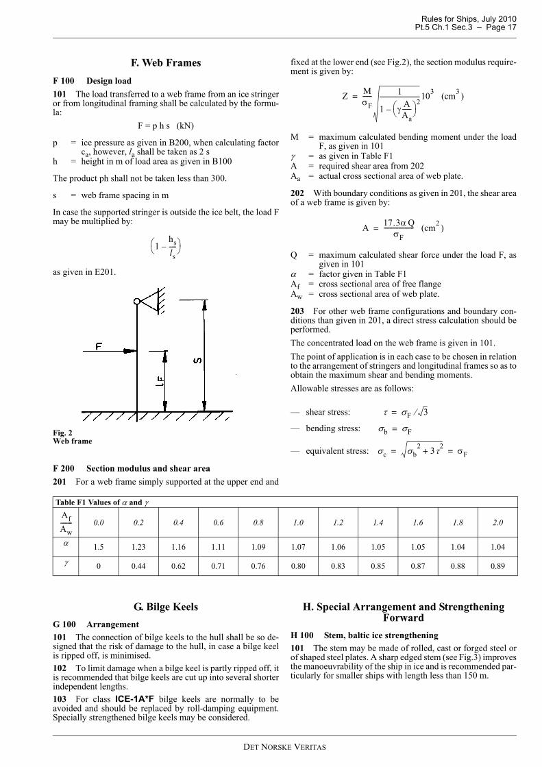
F. Web FramesF 100 Design load101 The load transferred to a web frame from an ice stringeror from longitudinal framing shall be calculated by the formu-la:
F = p h s (kN)
p = ice pressure as given in B200, when calculating factorca, however, la shall be taken as 2 s
h = height in m of load area as given in B100
The product ph shall not be taken less than 300.
s = web frame spacing in m
In case the supported stringer is outside the ice belt, the load Fmay be multiplied by:
as given in E201.
Fig. 2Web frame
F 200 Section modulus and shear area201 For a web frame simply supported at the upper end and
fixed at the lower end (see Fig.2), the section modulus require-ment is given by:
M = maximum calculated bending moment under the loadF, as given in 101
γ = as given in Table F1A = required shear area from 202Aa = actual cross sectional area of web plate.
202 With boundary conditions as given in 201, the shear areaof a web frame is given by:
Q = maximum calculated shear force under the load F, asgiven in 101
α = factor given in Table F1Af = cross sectional area of free flangeAw = cross sectional area of web plate.
203 For other web frame configurations and boundary con-ditions than given in 201, a direct stress calculation should beperformed.The concentrated load on the web frame is given in 101.The point of application is in each case to be chosen in relationto the arrangement of stringers and longitudinal frames so as toobtain the maximum shear and bending moments.Allowable stresses are as follows:
— shear stress:
— bending stress:
— equivalent stress:
G. Bilge KeelsG 100 Arrangement101 The connection of bilge keels to the hull shall be so de-signed that the risk of damage to the hull, in case a bilge keelis ripped off, is minimised.102 To limit damage when a bilge keel is partly ripped off, itis recommended that bilge keels are cut up into several shorterindependent lengths.103 For class ICE-1A*F bilge keels are normally to beavoided and should be replaced by roll-damping equipment.Specially strengthened bilge keels may be considered.
H. Special Arrangement and Strengthening Forward
H 100 Stem, baltic ice strengthening101 The stem may be made of rolled, cast or forged steel orof shaped steel plates. A sharp edged stem (see Fig.3) improvesthe manoeuvrability of the ship in ice and is recommended par-ticularly for smaller ships with length less than 150 m.
1hsls-----–⎝ ⎠
⎛ ⎞
Z MσF------ 1
1 γ AAa------⎝ ⎠
⎛ ⎞ 2–
--------------------------103 (cm3 )=
A 17.3α QσF
-------------------- (cm2 )=
τ σF 3⁄=
σb σF=
σc σb2 3τ2
+ σF= =
Table F1 Values of α and γ
0.0 0.2 0.4 0.6 0.8 1.0 1.2 1.4 1.6 1.8 2.0
α 1.5 1.23 1.16 1.11 1.09 1.07 1.06 1.05 1.05 1.04 1.04
γ 0 0.44 0.62 0.71 0.76 0.80 0.83 0.85 0.87 0.88 0.89
AfAw--------
DET NORSKE VERITAS
Rules for Ships, July 2010Pt.5 Ch.1 Sec.3 – Page 18
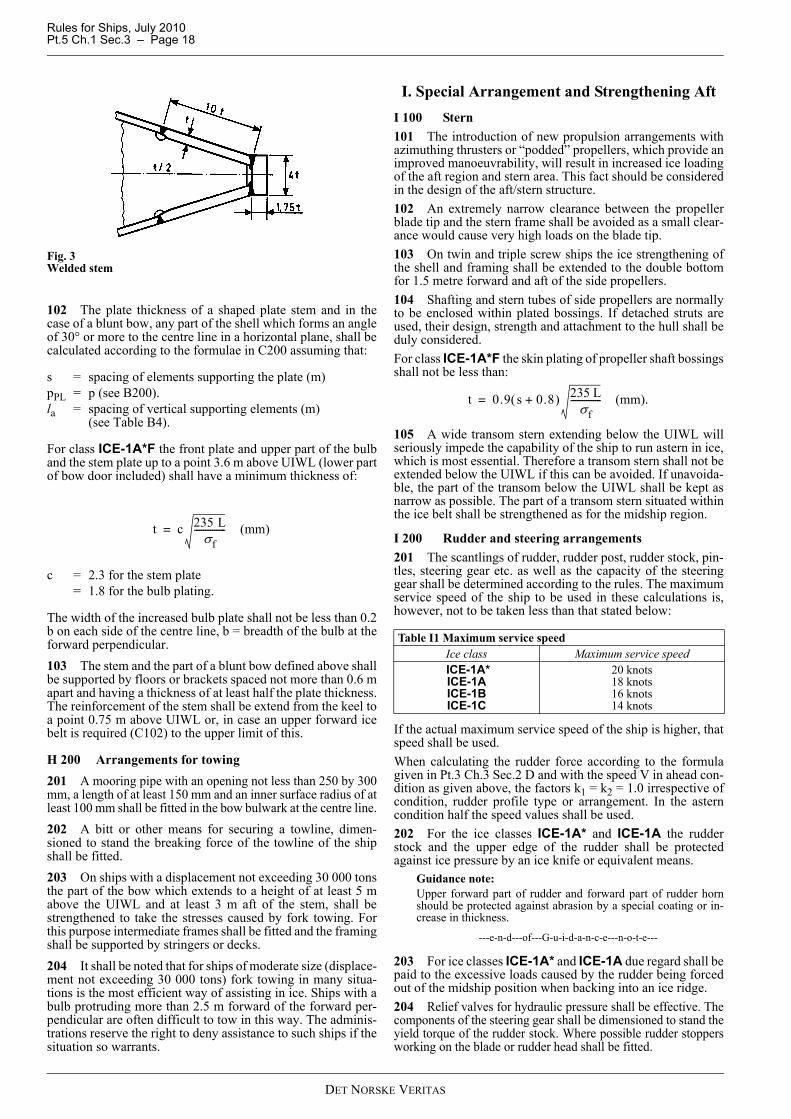
Fig. 3Welded stem
102 The plate thickness of a shaped plate stem and in thecase of a blunt bow, any part of the shell which forms an angleof 30° or more to the centre line in a horizontal plane, shall becalculated according to the formulae in C200 assuming that:
s = spacing of elements supporting the plate (m)pPL = p (see B200).la = spacing of vertical supporting elements (m)
(see Table B4).
For class ICE-1A*F the front plate and upper part of the bulband the stem plate up to a point 3.6 m above UIWL (lower partof bow door included) shall have a minimum thickness of:
c = 2.3 for the stem plate = 1.8 for the bulb plating.
The width of the increased bulb plate shall not be less than 0.2b on each side of the centre line, b = breadth of the bulb at theforward perpendicular.103 The stem and the part of a blunt bow defined above shallbe supported by floors or brackets spaced not more than 0.6 mapart and having a thickness of at least half the plate thickness.The reinforcement of the stem shall be extend from the keel toa point 0.75 m above UIWL or, in case an upper forward icebelt is required (C102) to the upper limit of this.
H 200 Arrangements for towing201 A mooring pipe with an opening not less than 250 by 300mm, a length of at least 150 mm and an inner surface radius of atleast 100 mm shall be fitted in the bow bulwark at the centre line.202 A bitt or other means for securing a towline, dimen-sioned to stand the breaking force of the towline of the shipshall be fitted.203 On ships with a displacement not exceeding 30 000 tonsthe part of the bow which extends to a height of at least 5 mabove the UIWL and at least 3 m aft of the stem, shall bestrengthened to take the stresses caused by fork towing. Forthis purpose intermediate frames shall be fitted and the framingshall be supported by stringers or decks.204 It shall be noted that for ships of moderate size (displace-ment not exceeding 30 000 tons) fork towing in many situa-tions is the most efficient way of assisting in ice. Ships with abulb protruding more than 2.5 m forward of the forward per-pendicular are often difficult to tow in this way. The adminis-trations reserve the right to deny assistance to such ships if thesituation so warrants.
I. Special Arrangement and Strengthening AftI 100 Stern101 The introduction of new propulsion arrangements withazimuthing thrusters or “podded” propellers, which provide animproved manoeuvrability, will result in increased ice loadingof the aft region and stern area. This fact should be consideredin the design of the aft/stern structure.102 An extremely narrow clearance between the propellerblade tip and the stern frame shall be avoided as a small clear-ance would cause very high loads on the blade tip.103 On twin and triple screw ships the ice strengthening ofthe shell and framing shall be extended to the double bottomfor 1.5 metre forward and aft of the side propellers.104 Shafting and stern tubes of side propellers are normallyto be enclosed within plated bossings. If detached struts areused, their design, strength and attachment to the hull shall beduly considered.For class ICE-1A*F the skin plating of propeller shaft bossingsshall not be less than:
105 A wide transom stern extending below the UIWL willseriously impede the capability of the ship to run astern in ice,which is most essential. Therefore a transom stern shall not beextended below the UIWL if this can be avoided. If unavoida-ble, the part of the transom below the UIWL shall be kept asnarrow as possible. The part of a transom stern situated withinthe ice belt shall be strengthened as for the midship region.
I 200 Rudder and steering arrangements 201 The scantlings of rudder, rudder post, rudder stock, pin-tles, steering gear etc. as well as the capacity of the steeringgear shall be determined according to the rules. The maximumservice speed of the ship to be used in these calculations is,however, not to be taken less than that stated below:
If the actual maximum service speed of the ship is higher, thatspeed shall be used.When calculating the rudder force according to the formulagiven in Pt.3 Ch.3 Sec.2 D and with the speed V in ahead con-dition as given above, the factors k1 = k2 = 1.0 irrespective ofcondition, rudder profile type or arrangement. In the asterncondition half the speed values shall be used.202 For the ice classes ICE-1A* and ICE-1A the rudderstock and the upper edge of the rudder shall be protectedagainst ice pressure by an ice knife or equivalent means.
Guidance note:Upper forward part of rudder and forward part of rudder hornshould be protected against abrasion by a special coating or in-crease in thickness.
---e-n-d---of---G-u-i-d-a-n-c-e---n-o-t-e---
203 For ice classes ICE-1A* and ICE-1A due regard shall bepaid to the excessive loads caused by the rudder being forcedout of the midship position when backing into an ice ridge.204 Relief valves for hydraulic pressure shall be effective. Thecomponents of the steering gear shall be dimensioned to stand theyield torque of the rudder stock. Where possible rudder stoppersworking on the blade or rudder head shall be fitted.
t c 235 Lσf
-------------- (mm)=
Table I1 Maximum service speedIce class Maximum service speed ICE-1A*ICE-1AICE-1BICE-1C
20 knots18 knots16 knots14 knots
t 0.9 s 0.8+( ) 235 Lσf
-------------- (mm).=
DET NORSKE VERITAS

Rules for Ships, July 2010 Pt.5 Ch.1 Sec.3 – Page 19
205 Parts of rudder within the ice belt shall have local thick-ness at least equivalent to the side shell in the afterbody.
J. Propulsion MachineryJ 100 Engine output101 Definition of engine outputThe engine output PS is the maximum output the propulsionmachinery can continuously deliver to the propeller(s). If theoutput of the machinery is restricted by technical means or byany regulations applicable to the ship, PS shall be taken as therestricted output.102 Documentation on boardMinimum engine output corresponding to the ice class shall begiven in the Classification Certificate.103 Required engine output for ice classesDefinitionsThe dimensions of the ship and some other parameters are de-fined below:
L = length of the ship between the perpendiculars (m)LBOW = length of the bow (m), Fig.4L PAR = length of the parallel midship body (m), Fig.4B = maximum breadth of the ship (m)T = actual ice class draughts of the ship (m) according to
A301A wf = area of the waterline of the bow (m2), Fig.4α = the angle of the waterline at B/4 (°), Fig.4ϕ1 = the rake of the stem at the centreline (°), Fig.4ϕ2 = the rake of the bow at B/4 (°), Fig.4DP = diameter of the propeller or outer diameter of nozzle
for the nozzle propeller, maximum 1.2 times propel-ler diameter (m)
HM = thickness of the brash ice in mid channel (m)HF = thickness of the brash ice layer displaced by the bow
(m).RCH = resistance (in Newton) of the ship in a channel with
brash ice and a consolidated layer (see formula in 104)Ke = factor depending on no. of propellers, CPP (or sim-
ilar), fixed pitch type (see Table J2)Ps = minimum engine outputC = empirical coefficients (misc. sub index)f = empirical factors (misc. sub index)g = empirical factors (misc. sub index).
Range of validityThe range of validity of the formulae for powering require-ments in 104 is presented in Table J1. When calculating the pa-rameter DP/T, T shall be measured at UIWL.
If the ship’s parameter values are beyond the ranges defined inTable J1, other methods for determining RCH shall be used asdefined in 105.
Fig. 4Definitions
104 The engine output requirement shall be calculated for:
— Upper Ice Waterlines (UIWL) and— Lower Ice Waterlines (LIWL),
as defined in Sec.1 B.In the calculations the ship's parameters which depend on thedraught shall be determined at the appropriate draught, but Land B shall be determined only at the UIWL. The engine out-
put shall not be less than the greater of these two outputs.The engine output PS shall not be less than that determined bythe formulae and in no case less than given in Table J3:
Guidance note:“New ships” – see A102 Guidance note.For “existing ICE-1A and ICE-1A* ships” see Pt.7 Ch.2 Sec.2 A.
---e-n-d---of---G-u-i-d-a-n-c-e---n-o-t-e---
Table J1 Parameter validity rangeParameter Minimum Maximumα [degrees] 15 55ϕ1 [degrees] 25 90ϕ2 [degrees] 10 90L [m] 65.0 250.0B [m] 11.0 40.0T [m] 4.0 15.0LBOW/L 0.15 0.40LPAR/L 0.25 0.75DP /T 0.45 0.75Awf /(L×B) 0.09 0.27
DET NORSKE VERITAS
Rules for Ships, July 2010Pt.5 Ch.1 Sec.3 – Page 20
RCH is the resistance in Newton of the ship in a channel withbrash ice and a consolidated layer:
Cμ = 0.15 cosϕ2 + sinψ sinαCμ ≥ 0.45 (minimum value)
Cψ = 0.047ψ − 2.115 and 0 if ψ ≤ 45°HF = 0.26 + (HMB)0.5
HM = 1.0 for ICE-1A and ICE-1A*= 0.8 for ICE-1B= 0.6 for ICE-1C.
C1 and C2 take into account a consolidated upper layer of thebrash ice and can be taken as zero for ice class ICE-1A, ICE-1B and ICE-1C.For ice class ICE-1A*:
For a ship with a bulbous bow, ϕ1 shall be taken as 90°.
f1 = 23 (N/m2)f2 = 45.8 (N/m)f3 = 14.7 (N/m)f4 = 29 (N/m2)g1 = 1 530 (N)g2 = 170 (N/m)g3 = 400 (N/m1.5)C3 = 845 (kg/(m2s2))C4 = 42 (kg/(m2s2))C5 = 825 (kg/s2)
105 Other methods of determining Ke or RCHFor an individual ship, in lieu of the Ke or RCH values definedin Table J2 and 104, the use of Ke or RCH values based on moreexact calculations or values based on model tests may be ap-proved. Such approval will be given on the understanding thatit can be revoked if experience of the ship’s performance inpractice motivates this.
Guidance note:For ships having the propulsion power determined by model testsor by means other than the rule formula, additional approval byFMA or SMA is necessary for ships requesting Finnish ice cer-tificate.
---e-n-d---of---G-u-i-d-a-n-c-e---n-o-t-e---
The design requirement for ice classes shall be a minimum speedof 5 knots in the following brash ice channels (see Table J4):
J 200 Materials201 Materials exposed to sea waterMaterials of components exposed to sea water, such as propel-ler blades, propeller hubs, and thruster body, shall have anelongation of not less than 15% on a test specimen, the gaugelength of which is five times the diameter. A Charpy V impacttest shall be carried out for materials other than bronze andaustenitic stainless steel. An average impact energy value of 20J taken from three tests shall be obtained at minus 10ºC. 202 Materials exposed to sea water temperatureMaterials exposed to sea water temperature shall be of ductilematerial. An average impact energy value of 20 J taken fromthree tests is to be obtained at minus 10ºC. This requirementapplies to blade bolts, CP mechanisms, shaft bolts, strut-podconnecting bolts etc. This does not apply to surface hardenedcomponents, such as bearings and gear teeth.
J 300 Design loads for propeller and shafting301 These regulations apply to propulsion machinery cover-ing open- and ducted-type propellers with controllable pitch orfixed pitch design for the ice classes ICE-IA*, ICE-IA, ICE-IBand ICE-IC. The given loads are the expected ice loads for thewhole ship's service life under normal operational conditions,including loads resulting from the changing rotational direc-tion of FP propellers. However, these loads do not cover off-design operational conditions, for example when a stoppedpropeller is dragged through ice.The regulations also apply to azimuting and fixed thrusters formain propulsion, considering loads resulting from propeller-ice interaction. However, the load models do not include pro-peller/ice interaction loads when ice enters the propeller of aturned azimuting thruster from the side (radially) or load casewhen ice block hits on the propeller hub of a pulling propeller.Ice loads resulting from ice impacts on the body of thrustershave to be estimated, but ice load formulae are not available302 Design ice conditionsIn estimating the ice loads of the propeller for ice classes, dif-ferent types of operation as given in Table J1 were taken intoaccount. For the estimation of design ice loads, a maximum iceblock size is determined. The maximum design ice block en-tering the propeller is a rectangular ice block with the dimen-sions Hice × 2Hice × 3Hice. The thickness of the ice block (Hice)is given in Table J2.
Table J2 Value of factor Ke for conventional propulsion systems*)
Propeller type or machinery
Numbers of propellers
Controllable pitch propeller or electric or hydraulic propulsion
machineryFixed pitch propeller
1 propeller 2.03 2.262 propellers 1.44 1.63 propellers 1.18 1.31
*) For advanced systems see J105.
Table J3 Minimum engine output PSICE-1A, ICE-1B and ICE-1C 1 000 kWICE-1A* 2 800 kW
shall not be taken less than 5 and not more than 20.
PS Ke
RCH1000------------⎝ ⎠
⎛ ⎞
DP-----------------
32---
(kW)=
RCH C1 C2 C3Cμ HF HM+( )2 B CψHF+( )
C4LPARHF2 C5
LT
B2-------⎝ ⎠
⎛ ⎞ 3AwfL
---------- (N)+
+ + +=
C1 f1BLPAR
2TB---- 1+
-------------------- 1 0.021ϕ1+( ) f2B f3LBOW f4BLBOW+ +( )+=
C2 1 0.063ϕ1+( ) g1 g2B+( ) g3 1 1.2TB----+⎝ ⎠
⎛ ⎞ B2
L-------+=
ψ arctanϕ2tanαsin
--------------⎝ ⎠⎛ ⎞=
3
2 ⎟⎠⎞
⎜⎝⎛
BLT
Table J4 Values of HMIce class HMICE-1A* 1.0 m and a 0.1 m thick consolidated layer of iceICE-1A 1.0 mICE-1B 0.8 mICE-1C 0.6 m
DET NORSKE VERITAS

Rules for Ships, July 2010 Pt.5 Ch.1 Sec.3 – Page 21
Table J1 Operation of the ship
ICE-1A* Operation in ice channels and in level ice. The ship may proceed by ramming
ICE-IA…1C Operation in ice channels
Table J2 Thickness of the design maximum ice block Hice entering the propellerIce Class ICE-1A* ICE-IA ICE-IB ICE-IC(Hice) 1.75 m 1.5 m 1.2 m 1.0 m
Table J3 List of symbols Symbol Unit Definition
A.P. the after perpendicular is the perpendicular at the after end of the length Lc m chord length of blade sectionc0.7 m chord length of blade section at 0.7R propeller radiusCP controllable pitchD m propeller diameterd m external diameter of propeller hubDlimit m limit value for propeller diameterEAR expanded blade area ratioFb kN maximum backward blade force for the ship’s service lifeFex kN ultimate blade load resulting from blade loss through plastic bendingFf kN maximum forward blade force for the ship’s service lifeFice kN ice load(Fice)max kN maximum ice load for the ship’s service lifeFP fixed pitchF.P. the forward perpendicular is the perpendicular at the intersection of the summer load waterline with the fore side
of the stem. For ships with unusual bow arrangements the position of the F.P. will be especially considered.h0 m depth of the propeller centreline from the winter waterlineHice m thickness of maximum design ice block entering to propellerI kgm2 equivalent mass moment of inertia of all parts on engine side of component under considerationIt kgm2 equivalent mass moment of inertia of the whole propulsion systemk shape parameter for Weibull distributionLIWL m lower ballast waterline in icem slope for SN curve in log/log scaleMBL kNm blade bending momentMCR maximum continuous ratingn rev/s propeller rotational speednn rev/s nominal propeller rotational speed at MCR in free running conditionNclass reference number of impacts per propeller rotational speed per ice classNice total number of ice loads on propeller blade for the ship’s service lifeNR reference number of load for equivalent fatigue stress (108 cycles)NQ number of propeller revolutions during a milling sequenceP0.7 m propeller pitch at 0.7R radiusP0.7n m propeller pitch at 0.7R radius at MCR in free running conditionP0.7b m propeller pitch at 0.7R radius at MCR in bollard conditionQ kNm torqueQemax kNm maximum engine torqueQmax kNm maximum torque on the propeller resulting from propeller-ice interactionQmotor kNm electric motor peak torqueQn kNm nominal torque at MCR in free running conditionQr kNm maximum response torque along the propeller shaft lineQsmax kNm maximum spindle torque of the blade for the ship’s service lifeR m propeller radiusr m blade section radiusT kN propeller thrustTb kN maximum backward propeller ice thrust for the ship’s service life
DET NORSKE VERITAS

Rules for Ships, July 2010Pt.5 Ch.1 Sec.3 – Page 22
Tf kN maximum forward propeller ice thrust for the ship’s service lifeTn kN propeller thrust at MCR in free running conditionTr kN maximum response thrust along the shaft linet m maximum blade section thicknessZ number of propeller bladesαi deg duration of propeller blade/ice interaction expressed in rotation angleγε the reduction factor for fatigue; scatter and test specimen size effectγν the reduction factor for fatigue; variable amplitude loading effectγm the reduction factor for fatigue; mean stress effectρ a reduction factor for fatigue correlating the maximum stress amplitude to the equivalent fatigue stress for 108 stress
cyclesσ0.2 MPa proof yield strength of blade materialσexp MPa mean fatigue strength of blade material at 108 cycles to failure in sea waterσfat MPa equivalent fatigue ice load stress amplitude for 108 stress cyclesσfl MPa characteristic fatigue strength for blade materialσref MPa reference stress (ultimate strength) σref = 0.6 σ0.2 + 0.4 σu
σref2 MPa reference stress (blade scantlings) σref2 = 0.7 σu or σref2 = 0.6 σ0.2 + 0.4 σu whichever is lessσst MPa maximum stress resulting from Fb or Ff
σu MPa ultimate tensile strength of blade material(σice)bmax MPa principal stress caused by the maximum backward propeller ice load(σice)fmax MPa principal stress caused by the maximum forward propeller ice load(σice)max MPa maximum ice load stress amplitude
Table J4 Definition of ice loadsLoad Definition Use of the load in design process
Fb The maximum lifetime backward force on a propeller blade resulting from propeller/ice interaction, including hydrody-namic loads on that blade. The direction of the force is perpen-dicular to 0.7 r/R chord line. See figure below
Design force for strength calculation of the propeller blade.
Ff The maximum lifetime forward force on a propeller blade re-sulting from propeller/ice interaction, including hydrodynam-ic loads on that blade. The direction of the force is perpendicular to 0.7 r/R chord line.
Design force for calculation of strength of the propeller blade.
Qsmax The maximum lifetime spindle torque on a propeller blade re-sulting from propeller/ice interaction, including hydrodynam-ic loads on that blade.
In designing the propeller strength, the spindle torque is automat-ically taken into account because the propeller load is acting on the blade as distributed pressure on the leading edge or tip area.
Tb The maximum lifetime thrust on propeller (all blades) result-ing from propeller/ice interaction. The direction of the thrust is the propeller shaft direction and the force is opposite to the hydrodynamic thrust.
Is used for estimation of the response thrust Tr. Tb can be used as an estimate of excitation for axial vibration calculations. Howev-er, axial vibration calculations are not required in the rules.
Tf The maximum lifetime thrust on propeller (all blades) result-ing from propeller/ice interaction. The direction of the thrust is the propeller shaft direction acting in the direction of hydro-dynamic thrust.
Is used for estimation of the response thrust Tr.Tf can be used as an estimate of excitation for axial vibration calculations. Howev-er, axial vibration calculations are not required in the rules.
Qmax The maximum ice-induced torque resulting from propeller/ice interaction on one propeller blade, including hydrodynamic loads on that blade.
Is used for estimation of the response torque (Qr) along the pro-pulsion shaft line and as excitation for torsional vibration calcula-tions.
Fex Ultimate blade load resulting from blade loss through plastic bending. The force that is needed to cause total failure of the blade so that plastic hinge is caused to the root area. The force is acting on 0.8 r/R. Spindle arm is to be taken as 2/3 of the dis-tance between the axis of blade rotation and leading/trailing edge (whichever is the greater) at the 0.8R radius.
Blade failure load is used to dimension the blade bolts, pitch con-trol mechanism, propeller shaft, propeller shaft bearing and trust bearing. The objective is to guarantee that total propeller blade failure should not cause damage to other components.
Qr Maximum response torque along the propeller shaft line, tak-ing into account the dynamic behaviour of the shaft line for ice excitation (torsional vibration) and hydrodynamic mean torque on propeller.
Design torque for propeller shaft line components.
Tr Maximum response thrust along shaft line, taking into account the dynamic behaviour of the shaft line for ice excitation (axial vibration) and hydrodynamic mean thrust on propeller.
Design thrust for propeller shaft line components.
Qg Fatigue torque at reduction gear for Ng load cycles. Design torque for reduction gear.
Table J3 List of symbols (Continued)Symbol Unit Definition
DET NORSKE VERITAS

Rules for Ships, July 2010 Pt.5 Ch.1 Sec.3 – Page 23
(Ice contact pressure at leading edge is shown with small arrows)Fig. 5Direction of the backward blade force resultant taken perpendicular to chord line at 0.7 r/R
J 400 Design loads401 The given loads are intended for component strengthcalculations only and are total loads including ice-inducedloads and hydrodynamic loads during propeller/ice interaction. 402 The values of the parameters in the formulae in this sec-tion shall be given in the units shown in the symbol list. 403 If the propeller is not fully submerged when the ship isin ballast condition, the propulsion system shall be designedaccording to ice class ICE-IA for ice classes ICE-IB and ICE-IC.
J 500 Design loads on propeller blades501 Fb is the maximum force experienced during the lifetimeof the ship that bends a propeller blade backwards when thepropeller mills an ice block while rotating ahead. Ff is the max-imum force experienced during the lifetime of the ship thatbends a propeller blade forwards when the propeller mills anice block while rotating ahead. Fb and Ff originate from differ-ent propeller/ice interaction phenomena, not acting simultane-ously. Hence they are to be applied to one blade separately.502 Maximum backward blade force Fb for open propellers
where
n is the nominal rotational speed (at MCR in free running con-dition) for a CP propeller and 85% of the nominal rotationalspeed (at MCR in free running condition) for an FP propeller.503 Maximum forward blade force Ff for open propellers
where
504 Loaded area on the blade for open propellersLoad cases 1-4 have to be covered, as given in Table J5 below,for CP and FP propellers. The load case 5 applies to reversiblepropellers in addition to the cases 1…4.
Shaft Direction
Fb Direction of rotation
Back / suction side
[ ] 23.0
7.027 DZ
EARDnFb ⋅⎥⎦⎤
⎢⎣⎡⋅⋅⋅= [kN]
limitDD ≤ (1)when
[ ] 4.13.0
7.023 iceb HDZ
EARDnF ⋅⋅⎥⎦⎤
⎢⎣⎡⋅⋅⋅= [kN]
limitDD > (2)when
4.185.0 icelimit HD ⋅= [m]
2250 DZ
EARFf ⋅⎥⎦⎤
⎢⎣⎡⋅= [kN]
limitDD ≤ (3)when
icef H
Dd
DZ
EARF ⋅⎟⎠⎞
⎜⎝⎛ −
⋅⋅⎥⎦⎤
⎢⎣⎡⋅=
1
1500 [kN]
limitDD > (4)when
icelimit H
Dd
D ⋅⎟⎠⎞
⎜⎝⎛ −
=1
2
DET NORSKE VERITAS
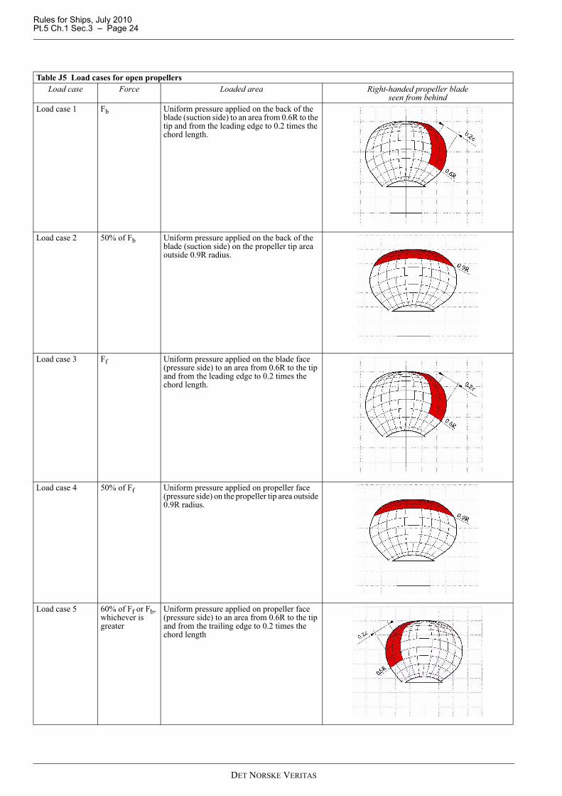
Rules for Ships, July 2010Pt.5 Ch.1 Sec.3 – Page 24
Table J5 Load cases for open propellersLoad case Force Loaded area Right-handed propeller blade
seen from behindLoad case 1 Fb Uniform pressure applied on the back of the
blade (suction side) to an area from 0.6R to the tip and from the leading edge to 0.2 times the chord length.
Load case 2 50% of Fb Uniform pressure applied on the back of the blade (suction side) on the propeller tip area outside 0.9R radius.
Load case 3 Ff Uniform pressure applied on the blade face (pressure side) to an area from 0.6R to the tip and from the leading edge to 0.2 times the chord length.
Load case 4 50% of Ff Uniform pressure applied on propeller face
(pressure side) on the propeller tip area outside 0.9R radius.
Load case 5 60% of Ff or Fb, whichever is greater
Uniform pressure applied on propeller face (pressure side) to an area from 0.6R to the tip and from the trailing edge to 0.2 times the chord length
DET NORSKE VERITAS

Rules for Ships, July 2010 Pt.5 Ch.1 Sec.3 – Page 25
505 Maximum backward blade ice force Fb for ducted pro-pellers
where
n is the nominal rotational speed (at MCR in free running con-dition) for a CP propeller and 85% of the nominal rotationalspeed (at MCR in free running condition) for an FP propeller.
506 Maximum forward blade ice force Ff for ducted propel-lers
where
507 Loaded area on the blade for ducted propellersLoad cases 1 and 3 have to be covered as given in Table J5 forall propellers, and an additional load case (load case 5) for anFP propeller, to cover ice loads when the propeller is reversed.
508 Maximum blade spindle torque Qsmax for open and duct-ed propellersThe spindle torque Qsmax around the axis of the blade fittingshall be determined both for the maximum backward bladeforce Fb and forward blade force Ff, which are applied as in Ta-ble J5 and Table J6. If the above method gives a value whichis less than the default value given by the formula below, the
default value shall be used.
where c0.7 is the length of the blade section at 0.7R radius andF is either Fb or Ff, whichever has the greater absolute value.
[ ] 23.0
7.05.9 DZ
EARDnFb ⋅⎥⎦⎤
⎢⎣⎡⋅⋅⋅= [kN]
limitDD ≤ (5)when
[ ] 4.16.03.0
7.066 iceb HDZ
EARDnF ⋅⋅⎥⎦⎤
⎢⎣⎡⋅⋅⋅= [kN]
limitDD > (6)when
icelimit HD ⋅= 4 [m]
2250 DZ
EARFf ⋅⎥⎦⎤
⎢⎣⎡⋅= [kN]
limitDD ≤when (7)
icef H
Dd
DZ
EARF ⋅⎟⎠⎞
⎜⎝⎛ −
⋅⋅⎥⎦⎤
⎢⎣⎡⋅=
1
1500 [kN]
limitDD >when (8)
icelimit H
Dd
D ⋅⎟⎠⎞
⎜⎝⎛ −
=1
2[m]
Table J6 Load cases for ducted propellersLoad case Force Loaded area Right handed propeller blade
seen from behindLoad case 1 Fb Uniform pressure applied on the back of the
blade (suction side) to an area from 0.6R to the tip and from the leading edge to 0.2 times the chord length.
Load case 3 Ff Uniform pressure applied on the blade face (pres-sure side) to an area from 0.6R to the tip and from the leading edge to 0.5 times the chord length.
Load case 5 60% of Ff or Fb, whichever is greater
Uniform pressure applied on propeller face (pressure side) to an area from 0.6R to the tip and from the trailing edge to 0.2 times the chord length.
7.025.0 cFQsmax ⋅⋅=Default value kNm] (9)[
DET NORSKE VERITAS
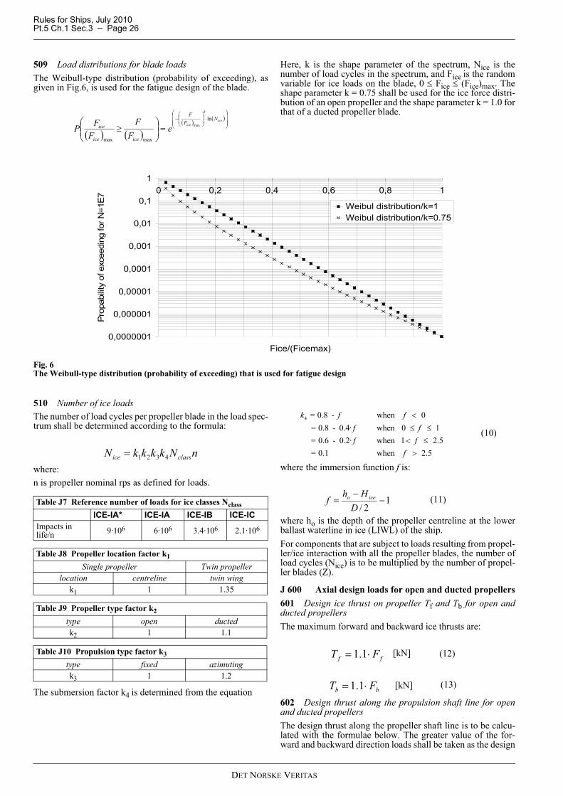
Rules for Ships, July 2010Pt.5 Ch.1 Sec.3 – Page 26
509 Load distributions for blade loadsThe Weibull-type distribution (probability of exceeding), asgiven in Fig.6, is used for the fatigue design of the blade.
Here, k is the shape parameter of the spectrum, Nice is thenumber of load cycles in the spectrum, and Fice is the randomvariable for ice loads on the blade, 0 ≤ Fice ≤ (Fice)max. Theshape parameter k = 0.75 shall be used for the ice force distri-bution of an open propeller and the shape parameter k = 1.0 forthat of a ducted propeller blade.
Fig. 6The Weibull-type distribution (probability of exceeding) that is used for fatigue design
510 Number of ice loadsThe number of load cycles per propeller blade in the load spec-trum shall be determined according to the formula:
where:n is propeller nominal rps as defined for loads.
The submersion factor k4 is determined from the equation
where the immersion function f is:
where ho is the depth of the propeller centreline at the lowerballast waterline in ice (LIWL) of the ship.For components that are subject to loads resulting from propel-ler/ice interaction with all the propeller blades, the number ofload cycles (Nice) is to be multiplied by the number of propel-ler blades (Z).
J 600 Axial design loads for open and ducted propellers601 Design ice thrust on propeller Tf and Tb for open andducted propellersThe maximum forward and backward ice thrusts are:
602 Design thrust along the propulsion shaft line for openand ducted propellersThe design thrust along the propeller shaft line is to be calcu-lated with the formulae below. The greater value of the for-ward and backward direction loads shall be taken as the design
( ) ( )( ) ( )
⎟⎟⎟
⎠
⎞
⎜⎜⎜
⎝
⎛⋅⎟⎟
⎠
⎞⎜⎜⎝
⎛−
=⎟⎟⎠
⎞⎜⎜⎝
⎛≥
ice
k
iceN
FF
iceice
ice eF
FF
FPln
maxmax
max
0,0000001
0,000001
0,00001
0,0001
0,001
0,01
0,1
10 0,2 0,4 0,6 0,8 1
Fice/(Ficemax)
Pro
pabi
lity
of e
xcee
ding
for N
=1E
7
Weibul distribution/k=1Weibul distribution/k=0.75
Table J7 Reference number of loads for ice classes NclassICE-IA* ICE-IA ICE-IB ICE-IC
Impacts in life/n 9·106 6·106 3.4·106 2.1·106
Table J8 Propeller location factor k1Single propeller Twin propeller
location centreline twin wingk1 1 1.35
Table J9 Propeller type factor k2 type open ductedk2 1 1.1
Table J10 Propulsion type factor k3type fixed azimutingk3 1 1.2
nNkkkkN classice 4321=
4 = 0.8 - when 0 = 0.8 - 0.4· when 0 1 = 0.6 - 0.2· when 1 2.5 = 0.1 when 2.5
k f ff ff f
f
<≤ ≤
< ≤>
(10)
12/
−−
=D
Hhf iceo (11)
ff FT ⋅= 1.1 [kN] (12)
bb FT ⋅= 1.1 [kN] (13)
DET NORSKE VERITAS
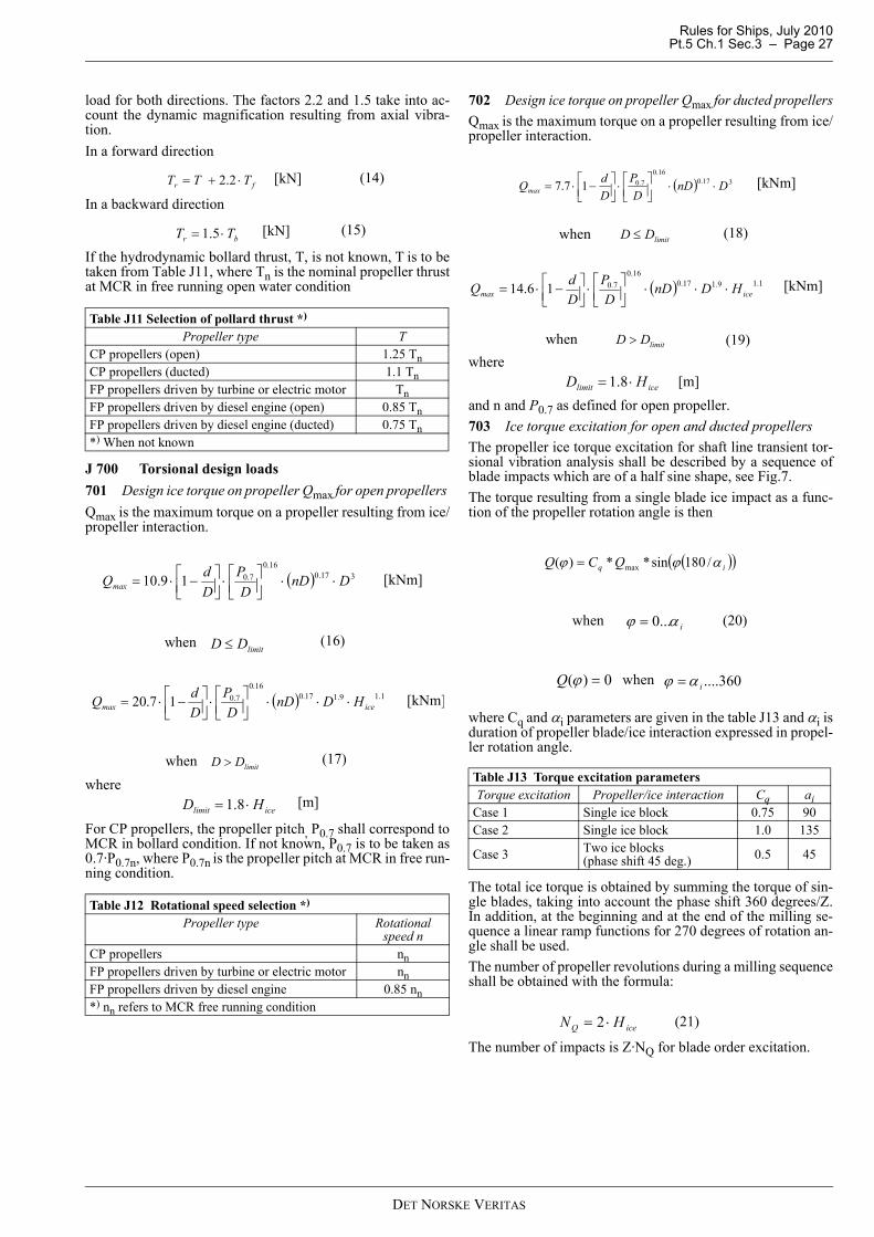
Rules for Ships, July 2010 Pt.5 Ch.1 Sec.3 – Page 27
load for both directions. The factors 2.2 and 1.5 take into ac-count the dynamic magnification resulting from axial vibra-tion. In a forward direction
In a backward direction
If the hydrodynamic bollard thrust, T, is not known, T is to betaken from Table J11, where Tn is the nominal propeller thrustat MCR in free running open water condition
J 700 Torsional design loads701 Design ice torque on propeller Qmax for open propellers Qmax is the maximum torque on a propeller resulting from ice/propeller interaction.
where
For CP propellers, the propeller pitch, P0.7 shall correspond toMCR in bollard condition. If not known, P0.7 is to be taken as0.7·P0.7n, where P0.7n is the propeller pitch at MCR in free run-ning condition.
702 Design ice torque on propeller Qmax for ducted propellersQmax is the maximum torque on a propeller resulting from ice/propeller interaction.
where
and n and P0.7 as defined for open propeller.703 Ice torque excitation for open and ducted propellersThe propeller ice torque excitation for shaft line transient tor-sional vibration analysis shall be described by a sequence ofblade impacts which are of a half sine shape, see Fig.7. The torque resulting from a single blade ice impact as a func-tion of the propeller rotation angle is then
where Cq and αi parameters are given in the table J13 and αi isduration of propeller blade/ice interaction expressed in propel-ler rotation angle.
The total ice torque is obtained by summing the torque of sin-gle blades, taking into account the phase shift 360 degrees/Z.In addition, at the beginning and at the end of the milling se-quence a linear ramp functions for 270 degrees of rotation an-gle shall be used. The number of propeller revolutions during a milling sequenceshall be obtained with the formula:
The number of impacts is Z·NQ for blade order excitation.
Table J11 Selection of pollard thrust *)
Propeller type TCP propellers (open) 1.25 TnCP propellers (ducted) 1.1 TnFP propellers driven by turbine or electric motor TnFP propellers driven by diesel engine (open) 0.85 TnFP propellers driven by diesel engine (ducted) 0.75 Tn*) When not known
Table J12 Rotational speed selection *) Propeller type Rotational
speed nCP propellers nnFP propellers driven by turbine or electric motor nnFP propellers driven by diesel engine 0.85 nn*) nn refers to MCR free running condition
fr TTT ⋅+= 2.2 [kN] (14)
br TT ⋅= 5.1 [kN] (15)
( ) 317.016.0
7.019.10 DnDD
PDdQmax ⋅⋅⎥⎦
⎤⎢⎣⎡⋅⎥⎦
⎤⎢⎣⎡ −⋅= [kNm]
limitDD ≤when (16)
( ) 1.19.117.016.0
7.017.20 icemax HDnDD
PDdQ ⋅⋅⋅⎥⎦
⎤⎢⎣⎡⋅⎥⎦
⎤⎢⎣⎡ −⋅= [kNm]
limitDD >when (17)
icelimit HD ⋅= 8.1 [m]
Table J13 Torque excitation parametersTorque excitation Propeller/ice interaction Cq ai
Case 1 Single ice block 0.75 90Case 2 Single ice block 1.0 135
Case 3 Two ice blocks (phase shift 45 deg.) 0.5 45
( ) 317.016.0
7.017.7 DnDD
PDdQmax ⋅⋅⎥⎦
⎤⎢⎣⎡⋅⎥⎦
⎤⎢⎣⎡ −⋅= [kNm]
limitDD ≤when (18)
( ) 1.19.117.016.0
7.016.14 icemax HDnDD
PDdQ ⋅⋅⋅⎥⎦
⎤⎢⎣⎡⋅⎥⎦
⎤⎢⎣⎡ −⋅= [kNm]
limitDD >when (19)
icelimit HD ⋅= 8.1 [m]
( )( )iq QCQ αϕϕ /180sin**)( max=
iαϕ ...0=when (20)
0)( =ϕQ when 360....iαϕ =
iceQ HN ⋅= 2 (21)
DET NORSKE VERITAS
Rules for Ships, July 2010Pt.5 Ch.1 Sec.3 – Page 28
For 90- and 135-degree single-blade impact sequences and 45 degree doubleblade impact sequence (figures apply for propellers with 4 blades.)Fig. 7The shape of the propeller ice torque excitation
704 Design torque along propeller shaft lineIf there is not any relevant first blade order torsional resonancewithin the designed operating rotational speed range extended20% above the maximum and 20% below the minimum oper-ating speeds, the following estimation of the maximum torquecan be used:
where I is equivalent mass moment of inertia of all parts on en-gine side of component under consideration and It is equivalentmass moment of inertia of the whole propulsion system. Allthe torques and the inertia moments shall be reduced to the ro-tation speed of the component being examined.If the maximum torque, Qemax, is not known, it shall be takenas follows, where Q motor is the electric motor peak torque:
If there is a first blade order torsional resonance within the de-signed operating rotational speed range extended 20% abovethe maximum and 20% below the minimum operating speeds,the design torque (Qr) of the shaft component shall be deter-mined by means of torsional vibration analysis of the propul-sion line.
J 800 Blade failure load801 The ultimate load resulting from blade failure as a resultof plastic bending around the blade root shall be calculatedwith the formula below. The ultimate load is acting on theblade at the 0.8R radius in the weakest direction of the blade.For calculation of the extreme spindle torque, the spindle armis to be taken as 2/3 of the distance between the axis of bladerotation and the leading/trailing edge (whichever is the greater)at the 0.8R radius.
where
c, t, and r are, respectively, the length, thickness, and radius ofthe cylindrical root section of the blade at the weakest sectionoutside the root filet.
J 900 Design principle901 The strength of the propulsion line shall be designed ac-cording to the pyramid strength principle. This means that theloss of the propeller blade shall not cause any significant dam-age to other propeller shaft line components.902 The propulsion system shall be designed in such a waythat the complete dynamic system is free from harmful torsion-al, axial, and bending resonances at a 1-order blade frequencywithin the designed running speed range, extended by 20 percent above and below the maximum and minimum operatingrotational speeds. If this condition cannot be fulfilled, a de-tailed vibration analysis has to be carried out in order to deter-mine that the acceptable strength of the components can beachieved.
J 1000 Propeller blade design1001 Calculation of blade stressesThe blade stresses shall be calculated for the design loads giv-en in J500. Finite element analysis shall be used for stress anal-ysis for final approval for all propellers. The following simplified formulae can be used in estimatingthe blade stresses for all propellers at the root area (r/R < 0.5).The root area dimensions will be accepted even if the FEManalysis would show greater stresses at the root area.
where the constant C1 is the “actual stress”/“stress obtainedwith beam equation”.If the actual value is not available, C1 should be taken as 1.6.
For relative radius r/R < 0.5F is the maximum of Fb and Ff, whichever is greater.1002 Acceptability criterion – maximum load (static)The following criterion for calculated blade stresses has to befulfilled.
Where σst is the calculated stress for the design load. If FEanalysis is used in estimating the stresses, von Mises stressesshall be used.σref 2 is the reference stress, defined as:
Table J14 Selection of maximum motor torque QemaxPropeller type Qemax
Propellers driven by electric motor Qmotor
CP propellers not driven by electric motor Qn
FP propellers driven by turbine Qn
FP propellers driven by diesel engine 0.75 Qn
00,10,20,30,40,50,60,70,80,9
1
0 200 400 600 800 1000 1200 1400
Rotaion angle [deg]
Q/Q
max
00,10,20,30,40,50,60,70,80,9
1
0 200 400 600 800 1000 1200 1400
Rotation angle
Q/Q
max
00,10,20,30,40,50,60,70,80,9
1
0 200 400 600 800 1000 1200 1400
Rotation angle [deg]
Q/Q
max
ter I
IQQQ ⋅+= maxmax [kNm] (22)
rDtc
F refex ⋅−⋅
⋅⋅⋅=
28.0300 2 σ
[kN] (24)
uref σσσ ⋅+⋅= 4.06.0 2.0
21 *100 ctMC BL
st =σ [MPa] (25)
FRRrM BL **)/75.0( −=
5.12 ≥st
ref
σσ (26)
DET NORSKE VERITAS
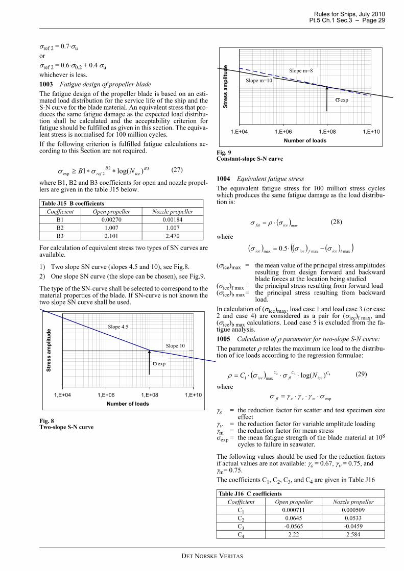
Rules for Ships, July 2010 Pt.5 Ch.1 Sec.3 – Page 29
σref 2 = 0.7·σuorσref 2 = 0.6·σ0.2 + 0.4 σuwhichever is less.1003 Fatigue design of propeller bladeThe fatigue design of the propeller blade is based on an esti-mated load distribution for the service life of the ship and theS-N curve for the blade material. An equivalent stress that pro-duces the same fatigue damage as the expected load distribu-tion shall be calculated and the acceptability criterion forfatigue should be fulfilled as given in this section. The equiva-lent stress is normalised for 100 million cycles. If the following criterion is fulfilled fatigue calculations ac-cording to this Section are not required.
where B1, B2 and B3 coefficients for open and nozzle propel-lers are given in the table J15 below.
For calculation of equivalent stress two types of SN curves areavailable.
1) Two slope SN curve (slopes 4.5 and 10), see Fig.8.2) One slope SN curve (the slope can be chosen), see Fig.9.
The type of the SN-curve shall be selected to correspond to thematerial properties of the blade. If SN-curve is not known thetwo slope SN curve shall be used.
Fig. 8Two-slope S-N curve
Fig. 9Constant-slope S-N curve
1004 Equivalent fatigue stressThe equivalent fatigue stress for 100 million stress cycleswhich produces the same fatigue damage as the load distribu-tion is:
where
(σice)max = the mean value of the principal stress amplitudesresulting from design forward and backwardblade forces at the location being studied
(σice)f max = the principal stress resulting from forward load (σice)b max= the principal stress resulting from backward
load.In calculation of (σice)max, load case 1 and load case 3 (or case2 and case 4) are considered as a pair for (σice)f max, and(σice)b max calculations. Load case 5 is excluded from the fa-tigue analysis.1005 Calculation of ρ parameter for two-slope S-N curve:The parameter ρ relates the maximum ice load to the distribu-tion of ice loads according to the regression formulae:
where
γε = the reduction factor for scatter and test specimen sizeeffect
γν = the reduction factor for variable amplitude loadingγm = the reduction factor for mean stressσexp = the mean fatigue strength of the blade material at 108
cycles to failure in seawater.
The following values should be used for the reduction factorsif actual values are not available: γε = 0.67, γν = 0.75, and γm= 0.75.The coefficients C1, C2, C3, and C4 are given in Table J16
Table J15 B coefficientsCoefficient Open propeller Nozzle propeller
B1 0.00270 0.00184B2 1.007 1.007B3 2.101 2.470
322exp )log(1 B
iceB
ref NB ∗∗≥ σσ (27)
1,E+04 1,E+06 1,E+08 1,E+10Number of loads
Stre
ss a
mpl
itude
Slope 4.5
Slope 10
σexp
Table J16 C coefficientsCoefficient Open propeller Nozzle propeller
C1 0.000711 0.000509C2 0.0645 0.0533C3 -0.0565 -0.0459C4 2.22 2.584
1,E+04 1,E+06 1,E+08 1,E+10Number of loads
Stre
ss a
mpl
itude Slope m=8
Slope m=10
σexp
( )maxicefat σρσ ⋅= (28)
( ) ( ) ( )( )maxmaxmax 5.0 biceficeice σσσ −⋅=
( ) 432 )log(max1C
iceC
flC
ice NC ⋅⋅⋅= σσρ (29)
expσγγγσ ε ⋅⋅⋅= mvfl
DET NORSKE VERITAS

Rules for Ships, July 2010Pt.5 Ch.1 Sec.3 – Page 30
1006 Calculation of ρ parameter for constant-slope S-N curveFor materials with a constant-slope S-N curve, see Fig.9 Theρ-factor shall be calculated with the following formula:
where k is the shape parameter of the Weibull distribution, k = 1.0 for ducted propellers and k= 0.75 for open propellers. NR is the reference number of load cycles (=100 million).Values for the G parameter are given in Table J17. Linear in-terpolation may be used to calculate the G value for other m/kratios than given in the Table J17.
1007 Acceptability criterion for fatigueThe equivalent fatigue stress at all locations on the blade has tofulfil the following acceptability criterion:
where
γε = the reduction factor for scatter and test specimen sizeeffect
γν = the reduction factor for variable amplitude loadingγm = the reduction factor for mean stressσexp = the mean fatigue strength of the blade material at 108
cycles to failure in seawater.
The following values should be used for the reduction factors ifactual values are not available: γε = 0.67, γν = 0.75, and γm= 0.75.
J 1100 Propeller bossing and CP mechanism1101 The blade bolts, the CP mechanism, the propeller boss,and the fitting of the propeller to the propeller shaft shall be de-signed to withstand the maximum and fatigue design loads, asdefined in J500. The safety factor against yielding shall begreater than 1.3 and that against fatigue greater than 1.5. In ad-dition, the safety factor for loads resulting from loss of the pro-peller blade through plastic bending as defined in J800 shall begreater than 1.0 against yielding.
J 1200 Propulsion shaft line1201 The shafts and shafting components, such as the thrustand stern tube bearings, couplings, flanges and sealing, shallbe designed to withstand the propeller/ice interaction loads asgiven in J500 - J700. The safety factor is to be at least 1.3.1202 The design torque Qr determined according to J700shall be applied for low cycle and high cycle strength analysisrespectively. 1203 Shafts and shafting componentsThe ultimate load resulting from total blade failure as definedin J800 should not cause yielding in shafts and shaft compo-nents. The loading shall consist of the combined axial, bend-ing, and torsion loads, wherever this is significant. Theminimum safety factor against yielding is to be 1.0 for bendingand torsional stresses.Forward of the after peak bulkhead, the shaft may be evenly ta-
pered down to 1.05 times the rule diameter of intermediate shaft,but not less than the actual diameter of the intermediate shaft.
J 1300 Design of shaft line components not specifically mentioned in FSICR1301 Below criteria are given for application of Pt.4 Ch.4 fordetermination of scantlings for intermediate shafts, couplings,reduction gears and crank shafts.Application factor KAice = Qr/Qn for low cycle criteria and/orstatic load criteria (ref. 1303). For components where fatigueis dimensioning, e.g. shaft and reduction gear, cumulative fa-tigue analysis are required. The actual Qr/Qn ratios shall be de-termined as given in 704.1302 The diameter of intermediate shafts shall be deter-mined based on methods given in Pt.4 Ch.4 Sec.1 B201.
a) When using the classification note 41.4 the necessary rein-forcement is determined by using Qr/Qn in the given crite-ria.
b) With Qr/Qn ≤ 1.4 the method in Pt.4 Ch.4 Sec.1 B206 maybe used, i.e. no ice reinforcement beyond 1A1 rules.
When using the method in Pt.4 Ch.4 Sec.1 B208, the minimumdiameter in item 3 of that paragraph shall be multiplied with:
(Qr/1.4 Qn)1/3, where Qr is relevant maximum value, but notless than 1.0.In item 4 of same paragraph, the vibratory torsional stress τv isreplaced by:τv = 0.5 (Qr/Qn - 1) Toand shall not exceed τC.1303 Regarding shaft connections, use Qr/Qn in Pt.4 Ch.4Sec.1 as follows:
— flange connections, see B300— shrink fit connections, see B400— keyed connections, see B500.
Connections transmitting ice axial load determined in J800from the propeller to the thrust bearing shall be capable oftransmitting relevant loads without consequential damage.1304 For reduction gears, use Qr/Qn in Pt.4 Ch.4 Sec.2.1305 For clutches, use Qr/Qn in Pt.4 Ch.4 Sec.3 B1001306 For torsional elastic coupling, use Qr/Qn in Pt.4 Ch.4Sec.5 B200.1307 For crank shafts in direct coupled diesel engines, seePt.4 Ch.3 Sec.1 B506.
J 1400 Azimuting main propulsors and other thrusters1401 In addition to the above requirements, special consid-eration shall be given to those loading cases which are extraor-dinary for propulsion units when compared with conventionalpropellers. The estimation of loading cases has to reflect theway of operation of the ship and the thrusters. In this respect,for example, the loads caused by the impacts of ice blocks onthe propeller hub of a pulling propeller have to be considered.Furthermore, loads resulting from the thrusters operating at anoblique angle to the flow have to be considered. The steeringmechanism, the fitting of the unit, and the body of the thrustershall be designed to withstand the loss of a blade without dam-age. The loss of a blade shall be considered for the propellerblade orientation which causes the maximum load on the com-ponent being studied. Typically, top-down blade orientationplaces the maximum bending loads on the thruster body.1402 Azimuth thrusters shall also be designed for estimatedloads caused by thruster body/ice interaction. The thrusterbody has to stand the loads obtained when the maximum iceblocks, which are given in the “Design ice conditions” section,
Table J17 Value for the G parameter for different m/k ratios m/k G m/k G m/k G3 6 5.5 287.9 8 40 320
3.5 11.6 6 720 8.5 119 2924 24 6.5 1871 9 362 880
4.5 52.3 7 5040 9.5 1.133•106
5 120 7.5 14034 10 3.623•106
kice
m
R
ice NNNG
1/1
))(ln( −
⎟⎟⎠
⎞⎜⎜⎝
⎛=ρ (30)
5.1≥fat
fl
σσ
(31)
expσγγγσ ε ⋅⋅⋅= mvfl
DET NORSKE VERITAS

Rules for Ships, July 2010 Pt.5 Ch.1 Sec.3 – Page 31
strike the thruster body when the ship is at a typical ice operat-ing speed. In addition, the design situation in which an icesheet glides along the ship's hull and presses against the thrust-er body should be considered. The thickness of the sheetshould be taken as the thickness of the maximum ice block en-tering the propeller, as defined in the “Design ice conditions”section.1403 Tunnel thrustersIce strengthening of tunnel thrusters is not required.1404 Other thrustersThrusters other than propulsion thrusters and tunnel thrustersneed only comply with the relevant requirements in J if theyshall be used in ice conditions or for any reason be exposed toice loads.For thrusters that are not intended for use in ice conditions, thiswill be stated in the class certificate and on signboards fitted atall relevant manoeuvring stands.1405 The relevant structure parts of non-retractable thrustersshall be strengthened with respect to ice loads, independent ofwhether they are used in ice conditions or not.
J 1500 Alternative design1501 ScopeAs an alternative to J300 - J1400, a comprehensive designstudy may be carried out to the satisfaction of the Administra-tion. The study has to be based on ice conditions given for dif-ferent ice classes in A200. It has to include both fatigue andmaximum load design calculations and fulfil the pyramidstrength principle, as given in J900.1502 LoadingLoads on the propeller blade and propulsion system shall bebased on an acceptable estimation of hydrodynamic and ice loads.1503 Design levelsThe analysis is to indicate that all components transmittingrandom (occasional) forces, excluding propeller blade, are notsubjected to stress levels in excess of the yield stress of thecomponent material, with a reasonable safety margin. Cumulative fatigue damage calculations are to indicate a rea-sonable safety factor. Due account is to be taken of materialproperties, stress raisers, and fatigue enhancements.Vibration analysis is to be carried out and is to indicate that thecomplete dynamic system is free from harmful torsional reso-nances resulting from propeller/ice interaction.
K. Miscellaneous Machinery RequirementsK 100 Starting arrangements101 The capacity of the air receivers shall be according to therequirements in Pt.4 Ch.6 Sec.5 I.If the air receivers serve any other purposes than starting thepropulsion engine, they shall have additional capacity suffi-cient for these purposes.The capacity of the air compressors shall be sufficient for charg-ing the air receivers from atmospheric to full pressure in one (1)hour, except for a ship with the ice class ICE-1A* if its propul-sion engine has to be reversed for going astern, in which case thecompressors shall be able to charge the receivers in half an hour.
K 200 Sea inlet and cooling water systems201 The cooling water system shall be designed to ensuresupply of cooling water when navigating in ice. The sea cool-ing water inlet and discharge for main and auxiliary enginesshall be so arranged that blockage of strums and strainers isprevented.
For this purpose at least one cooling water inlet chest shall bearranged as follows:
1) The sea inlet shall be situated near the centre line of theship and well aft if possible. The inlet grids shall be spe-cially strengthened.
2) As a guidance for design the volume of the chest shall beabout one cubic metre for every 750 kW engine output ofthe ship including the output of the auxiliary engines nec-essary for the ship's service.
3) To allow for ice accumulation above the pump suction theheight of the sea chest shall not be less than:
Vs = volume of sea chest according to item 2.The suction pipe inlet shall be located not higher thanhmin/3 from top of sea chest.
4) A pipe for discharge cooling water, allowing full capacity dis-charge, shall be connected to the chest. Where the sea chestvolume and height specified in 2 and 3 are not complied with,the discharge shall be connected to both sea chests. At leastone of the fire pumps shall be connected to this sea chest orto another sea chest with de-icing arrangements.
5) The area of the strum holes shall be not less than four (4)times the inlet pipe sectional area.
If there are difficulties in meeting the requirements of 2) and 3)above, two smaller chests may be arranged for alternating in-take and discharge of cooling water. The arrangement and sit-uation otherwise shall be as above.Heating coils may be installed in the upper part of the chest orchests.Arrangements using ballast water for cooling purposes may beuseful as a reserve in ballast condition but can not be acceptedas a substitute for sea inlet chests as described above.
K 300 Ballast system301 An arrangement to prevent freezing of the ballast watershall be provided for in ballast tanks located fully or partlyabove the LIWL, adjacent to the ship's shell, and needed to befilled for operation in ice conditions according to A302. Forthis purpose the following ambient temperatures shall be takenas design conditions:
— sea water temperature: 0°C— air temperature: –10°C.
Necessary calculations shall be submitted.302 When a tank is situated partly above the LIWL, an air-bubbling arrangement or a vertical heating coil, capable ofmaintaining an open hole in the ice layer, will normally be ac-cepted.The required heat-balance calculations may then be omitted.
Guidance note:It is assumed that, before pumping of ballast water is com-menced, proper functioning of level gauging arrangements isverified and air pipes are checked for possible blockage by ice.
---e-n-d---of---G-u-i-d-a-n-c-e---n-o-t-e---
L. Guidelines for Strength Analysis of the Pro-peller Blade using Finite Element Method
See Appendix A for guidelines on strength analysis of the pro-peller blade using finite element method.
hmin 1.5 Vs3≥
DET NORSKE VERITAS
Rules for Ships, July 2010Pt.5 Ch.1 Sec.4 – Page 32
SECTION 4 VESSELS FOR ARCTIC AND ICE BREAKING SERVICE
A. General
A 100 Classification 101 The requirements in this section apply to icebreakersand to passenger and cargo vessels intended to operate unas-sisted in ice-infested waters of sub-Arctic, Arctic and/or Ant-arctic regions.102 Vessels intended for ice breaking as their main purposeand built in compliance with the following requirements maybe given one of the class notations Icebreaker ICE-05 (or -10 or -15) or Icebreaker POLAR-10 (or -20 or -30), which-ever is relevant.Vessels built for another main purpose, while also intended forice breaking, may be given the additional class notation ICE-05 (or -10 or -15) or the notation POLAR-10 (or -20 or -30).103 Arctic class vessels intended for special services whereintermediate ice condition values are relevant may, upon spe-cial consideration, be given intermediate notations (e.g. PO-LAR-25).104 For POLAR class vessels the design ambient air temper-ature on which the classification has been based will be giventhe special feature notation DAT(-X°C). For details, see Sec.7.105 For vessels with the class notation Icebreaker, and forother POLAR class vessels the maximum operational speedon which the ramming design requirements have been basedwill be stated in the “Appendix to the classification certifi-cate”. The operational speed is in no case to be taken as smallerthan stated in 300 for the various class notations.
A 200 Scope201 The following matters are covered by the classification:
— materials in structures exposed to low ambient air temper-atures
— subdivision, intact and damage stability— hull girder longitudinal and transverse strength— local hull structures exposed to ice loads— rudders and steering gears— propellers and propulsion machinery— sea suctions for cooling water— air starting systems.
MDHT Mean Daily High (or maximum) TemperatureMDAT Mean Daily Average TemperatureMDLT Mean Daily Low (or minimum) TemperatureMAMDHT Monthly Average of MDHTMAMDAT Monthly Average of MDATMAMDLT Monthly Average of MDLTMEHT Monthly Extreme High Temperature
(ever recorded)MELT Monthly Extreme Low Temperature
(ever recorded).Mean: Statistical mean over observation period (at least 20years).Average: Average during one day and night.
A 300 Design principles and assumptions301 Each class notation is related to a particular ice conditionthat the vessel is expected to encounter. Relevant design iceconditions are as given in Table A1. In case intermediate ice
conditions are relevant (see 103), nominal ice strength shall berelated to the selected nominal ice thickness.302 Vessels with the class notation Icebreaker, and otherPOLAR class vessels are expected to encounter pressure ridg-es and other ice features of significantly greater thickness thanthe average thicknesses specified in Table A1. Vessels with theclass notation POLAR only are assumed not to make repeatedramming attempts if the ice fails to break during the first (oc-casional) ram unless the vessel's speed is kept well below thedesign ramming speed. Vessels with class notation Icebreak-er may make several consecutive attempts to break the ice atmaximum ramming speed. The design speed in ice infestedwaters when ramming may occur, VRAM, shall be specified bythe builder. In general this speed shall not be taken less than:
VRAM = VB + VH (m/s)
VB = specified continuous speed, when breaking maximumaverage ice thickness
VH = speed addition in thinner ice = hice (see Table A1).
In no case the design ramming speed shall be taken less than:VRAM (minimum)
= 2.0 m/s (3.9 knots) for the notation POLAR-10 = 3.0 m/s (5.8 knots) for the notation POLAR-20 = 4.0 m/s (7.8 knots) for the notation POLAR-30.
For vessels with the class notation Icebreaker the minimumspeed is 2 m/s (3.9 knots) but not less than 1.5 times the speedspecified above when POLAR class notation is also specified.
A 400 Definitions401 General symbols and terms are also given in Sec.1 B100.402 Symbols
VRAM = design speed in m/s when ramming may occur, seealso 302
σice = nominal strength of ice in N/mm2, see Table A1hice = average ice thickness in m, see Table A1EKE = vessel's kinetic energy before ramming = 1/2 Δ (VRAM)2 (kNm)α, γ = bow shape angles, see Fig.1CWL = vessel's water line area coefficient on UIWLs = stiffener spacing in m, measured along the plating.
Stiffener web thickness may be deductedl = stiffener span in m, measured along the top flange of
the member.For determining the section modulus and shear areaof the stiffener, the depth of stiffener on crossingpanel and 2/3 of the arm length of end bracket(s)(except at simply supported ends) may be deductedwhen deciding the span.
S = girder span in m. The web height of in-plane girdersmay be deducted
t = rule thickness of plating in mmtk = corrosion addition in mmtw = rule web thickness in mmZ = rule section modulus in cm3
AW = rule web area in cm2, defined as the web thicknesstimes the web height including thickness of flanges
A = rule cross-sectional area in cm2
DET NORSKE VERITAS

Rules for Ships, July 2010 Pt.5 Ch.1 Sec.4 – Page 33
Fig. 1Bow shape angles
403 The hull structure (shell plating with stiffening) to be re-inforced against local ice loads is divided into 7 different areas.The areas are defined as follows (see also Fig.2):Bow areaLongitudinally from stem to a line parallel to and 0.04 L aft ofthe border line of flat side of hull forward. If the hull breadth isincreased over a limited length forward of the flat side the bowarea need normally not extend aftwards beyond the widest sec-tion of each waterline.The bow area need not extend aftwards beyond 0.3 L from theforward perpendicular.Vertically from a line defined by the distance zlm below LIWL(aft) and the intersection between the keel line and the stemline (forward) to a line defined by the distances zua (aft) and zuf(forward) above UIWL. For ships with an ice knife fitted, theline of the lower vertical extension may be drawn to a point0.04 L aft of the upper end of the knife and further down to thebase line (see also Fig.2).
Fig. 2Extension of bow area
Stem areaThe part of the bow area between the stem line and a line 0.06L aft of the stem line or 0.125 B outboard from the centre line,whichever is first reached.
Vertically from a line defined by the distance zla below LIWL,to a line defined by the distance zua above UIWL.Stern areaLongitudinally from the stern to a line parallel to and 0.04 Lforward of the border line of flat side of hull aft, or to a line0.2 L aft of amidships, whichever is the aftermost.Vertically from a line defined by the distance zla below LIWL,to a line defined by a distance zua above UIWL.Midship areaLongitudinally from the stern area to the bow area.Vertically from a line defined by the distance zlm below LIWL,to a line defined by a distance zua above UIWL. Bottom areaLongitudinally aft of 0.3 L from forward perpendicular andtransversely over the flat bottom including deadrise. For shipswith bow ice knife, the bottom area may be extended forwardto the ice knife.Lower transition areaTransition area between the bottom area and the adjacent stern,and midship areas respectively.Lower bow areaThe area below the bow area.UIWL and LIWL are defined in Sec.1 B200.Values of zla, zlm, zua, and zuf are given for various class nota-tions in Table A2.
A 500 Documentation501 UIWL and LIWL as well as the border line of flat sideshall be indicated on the shell expansion plan together with theice reinforced areas as given in Fig.3.502 Maximum design ramming speed (VRAM) in ice infestedwaters as well as design speed for continuous ice breaking op-erations (VB) shall be stated on the midship section plan forships with class notations POLAR or Icebreaker.503 For documentation in connection with stability and wa-tertight integrity, see L300.504 Applicable design specifications for the operation of thevessel in ice infested waters shall be stated in the ship's loadingmanual, see Pt.3 Ch.1 Sec.5 F and Pt.3 Ch.2 Sec.4 E.
Table A1 Ice conditionsClass notation Type of ice encountered Nominal ice strength
σice (N/mm2)Nominal ice thickness
hice (m)Limiting impact conditions
ICE-05 ICE-10 ICE-15
Winter ice with pressure ridges4.2 5.6 7.0
0.5 1.0 1.5
No ramming anticipated
POLAR-10 POLAR-20 POLAR-30
Winter ice with pressure ridges and multi-year ice-floes and glacial ice inclusions
7.0 8.5
10.0
1.0 2.0 3.0
Occasional ramming
Icebreaker As above As above As above Repeated ramming
F.P. 1 m
α
γ
BUTTOCK
STEMLINE
BASE LINE
UIWL
UIWL
CENTRE LINE
Z uaZ lm
Z uf
UIWLLIWL
0.3 L
0.04 L
Table A2 Vertical extent of ice reinforced areasClass notation Parameters for vertical extent (m)
zla zlm1) zua zuf
ICE-05 ICE-10 ICE-15
1.7 2.2 4.6
1.1 1.6 3.7
0.8 1.0 1.9
1.5 2.0 2.5
POLAR-10 POLAR-20 POLAR-30
2.9 6.0 11.9
2.3 4.6 9.2
1.4 2.8 4.2
2.2 3.7 5.2
1) zlm (maximum) = the vertical distance from the LIWL to the point on the frame contour amidships where the tangent is at 45 degrees.
DET NORSKE VERITAS

Rules for Ships, July 2010Pt.5 Ch.1 Sec.4 – Page 34
Possible design specifications are:
— allowable draughts, maximum and minimum— loading conditions with respect to strength and stability— ambient temperature— design speed— ramming speed— instruction for filling of ballast tanks— astern operation in ice.
505 Where ice exposed plating is fitted with a special wearaddition, the plate thickness including wear addition shall begiven on the shell expansion plan in addition to the net thick-ness required by the rules.
Fig. 3Ice reinforced areas
506 Documentation requirements for stability and watertightintegrity can be found in L200.
B. Materials and Corrosion ProtectionB 100 Design temperatures101 Steel grades to be used in hull structural members shallbe determined based on the design temperature for the struc-ture in question with requirements as given in Sec.7.102 For POLAR class notations steel grades in exposedstructures (external structure as defined in Sec.7) shall bebased on air temperatures lower than those generally anticipat-ed for world wide operation. Unless a service restriction nota-tion is also given, limiting the navigation to specified areasand/or time of year, the design temperature shall not be takenhigher than -30°C (corresponding extreme low temperature -50ºC).For operation in lower design temperatures, this must be clear-ly specified.103 For ICE class notations no special consideration for lowambient air temperatures are given unless specified by thebuilder.
B 200 Selection of steel grades201 Plating materials for various structural categories of ex-
posed members above the ballast waterline of vessels withclass notation POLAR shall not be of lower grades than ob-tained from Sec.7 using design temperatures as defined in 100.Plating materials of non-exposed members and of vessels withclass notation ICE shall not be of lower grade than obtained ac-cording to Pt.3 Ch.1 Sec.2 Table B1and Pt.3 Ch.2 Sec.2 TableB1.Cranes shall be in compliance with DNV Standard for Certifi-cation No. 2.22 “Lifting Appliances”.
B 300 Coatings301 Wear resistant coating is assumed used for the externalsurfaces of plating in ice reinforced areas.
B 400 Corrosion additions401 Hull structures are in general to be given a corrosion ad-dition tk as required by the main class, see Pt.3 Ch.1 Sec.2 andor Pt.3 Ch.2 Sec.2.
C. Ship Design and ArrangementC 100 Hull form101 The bow shall be shaped so that it can break level ice ef-fectively and at continuous speed, up to a thickness as indicat-ed in Table A1 for the various class notations.
Zuf
ZuaLWLBWL
A.P.
0.2L 0.3L
F.P.
0.04L 0.04L
0.06L(max)
Zlm
ZlaZla
Zua
BORDER LINE OF FLAT SIDE
MIDSHIP AREA
BOTTOM AREALOWER TRANSITION AREA
STERN AREA BOW AREA
LOWER BOW
LOWER TURN OF THE BILGE
BORDER LINE OF FLAT SIDE(AT LWL)
0.125 B(max)
Zuf
ZuaLWLBWL
A.P.
0.2L 0.3L
F.P.
0.04L 0.04L
0.06L(max)
Zlm
ZlaZla
Zua
BORDER LINE OF FLAT SIDEBORDER LINE OF FLAT SIDE
MIDSHIP AREA
BOTTOM AREALOWER TRANSITION AREA
STERN AREA BOW AREA
LOWER BOW
MIDSHIP AREA
BOTTOM AREALOWER TRANSITION AREA
STERN AREA BOW AREA
LOWER BOW
LOWER TURN OF THE BILGE
BORDER LINE OF FLAT SIDE(AT LWL)
0.125 B(max)
LOWER TURN OF THE BILGELOWER TURN OF THE BILGE
BORDER LINE OF FLAT SIDE(AT LWL)
BORDER LINE OF FLAT SIDE(AT LWL)
0.125 B(max)
LIWLUIWL
(AT UIWL)
DET NORSKE VERITAS
Rules for Ships, July 2010 Pt.5 Ch.1 Sec.4 – Page 35
102 Vessels with class notation Icebreaker, and otherPOLAR class vessels shall have a bow shape so that the bowwill ride up on the ice when encountering pressure ridges orsimilar ice features that will not break on the first ramming.103 Masts, rigging, superstructures, deckhouses and otheritems on deck shall be designed and arranged so that excessiveaccumulation of ice is avoided. The rigging shall be kept at aminimum, and the surfaces of erections on deck shall be aseven as possible.104 Weathertight doors and hatches shall be suitably de-signed for use in low temperature environment with respect to:
— strength of cleats and the choice of steel with adequateductility
— flexibility of packing material— ease of maintenance, e.g. interior accessible grease fittings— ease of operations, e.g. low weight and preference to cen-
tral handwheel operated cleats.
105 Air pipe closures shall be designed so that icing or freez-ing will not make them inoperable.106 Freeing ports shall be designed so that blocking by ice isavoided as far as possible and so that they are easily accessiblefor removal of ice should blocking occur.
C 200 Appendages201 In vessels with class notation Icebreaker and in otherPOLAR class vessels an ice knife may be required forward toavoid excessive beaching and submersion of the deck aft. Thisrequirement will be based on consideration of design speedand freeboard, and may result in additional requirements re-garding accelerations and strength.202 Ice horns shall be fitted directly abaft each rudder insuch a manner that:
— the upper edge of the rudder is protected within two de-grees to each side of midposition when going astern, and
— ice is prevented from wedging between the top of the rud-der and the vessel's hull.
C 300 Mooring equipment301 The housing arrangement for anchors shall be designedso that possible icing will not prevent the anchor from fallingwhen released.
D. Design Loads D 100 Ice impact forces on the bow101 The vertical design force component due to head onramming (not applicable to vessels with class notation ICE on-ly) is given by:
P ZR = PR FEL (kN)
CR = 1 for the class notation POLAR only = 2 for the class notation IcebreakerEKE, σice, α and γ as defined in A400.L as defined in Sec.1 B100.
IV = moment of inertia in m4 about the horizontal neutralaxis of the midship section.
102 The total design force normal to the shell plating in thebow area due to an oblique impact with an ice feature is givenby:
PZR = vertical ramming load as given in 101
L and B as defined in Sec.1 B100.EKE, σice, α and γ as defined in A400.
D 200 Beaching forces201 The vertical design force resulting from beaching on alarge ice feature (not applicable to vessels with class notationICE only) is in general given by:
GB =
kb = 2 go (1 − rfw)rfw = reduction factor due to energy lost in friction and
waves = 0.3.
EKE, σice, CWL, γ and α as defined in A400.L, B and go as defined in Sec.1 B100.202 For vessels with vertical ram bow the vertical designforce in beaching need not be taken larger than:
X = horizontal distance from FPICE to centre of ver-tical ram bow in m
FPICE = intersection point of stem line and deepest ice-breaking waterline
C WL = waterline area coefficient.L and B as defined in Sec.1 B100.
D 300 Ice compression loads amidships301 All vessels shall withstand line loads acting simultane-
PR = 28CREIMP
γtan--------------------⎝ ⎠
⎛ ⎞0.6
σice αtan( )0.4 in general
For spoon bows: αtan 1.2 B0.1
γcos---------------=
EIMP = EKEγ2tan
γ 2.5+2tan
---------------------------
FEL = EIMP
EIMP CLPR2
+------------------------------------
CL = L3
3 1010IV×--------------------------
POIPZRFSIDE
γcos------------------------- (kN)=
FSIDE = 1.9
αtan( )0.4-----------------------
σiceEKE----------⎝ ⎠
⎛ ⎞0.05
in general
α = 1tan .2 B0.1
γcos--------------- for spoon shaped bows
PZB GB kbEKELB (kN)=
CWL CWL 0.5–( )CWL 1+( )
-------------------------------------------
PZB10.6CWLBLX γtan
1 15 0.55 X L⁄( )–[ ]2+
------------------------------------------------------ (kN)=
DET NORSKE VERITAS

Rules for Ships, July 2010Pt.5 Ch.1 Sec.4 – Page 36
ously in the horizontal plane at the water level on both sides ofthe hull. These loads are assumed to arise when a vessel istrapped between moving ice floes.302 The design line loads shall be taken as:
hice = average ice thickness as defined in A400βf = angle of outboard flare at the waterlevel. The outboard
flare angle shall not be taken as less than 10 degrees.
D 400 Local ice pressure401 All vessels shall withstand local ice pressure as definedfor the different ice class notations and as applied to the differ-ent ice reinforced areas. The design pressure shall be appliedover a corresponding contact area reflecting the type of load inquestion.402 The basic ice pressure is in general to be taken as:
po = 1 000 FA σice (kN/m2)
FA = correction factor for ice reinforced area in question = 1.0 for bow and stem area in general. = 0.6 for midship area in general = 0.5 for midship area if ship breadth in bow area larger
than ship breadth in midship area= 0.20 for bottom area of vessels with notation
Icebreaker or POLAR = 0.10 for vessels with notation ICE only = 0.6 for stern area in general = 0.8 for stern area in ships with class notation
Icebreaker = 1.0 for the stern area in ships with class notation
Icebreaker or POLAR, and 0.8 for ships with ICEnotations, fitted with pod or thruster propulsion units,and designed for continuous operation astern. Thestern area structure shall in general be dimensioned asoutlined for bow structure. See also G700.
For the transition areas 2/3 of the FA-value for the adjacentarea above may be used in general. σice as defined in A400.403 The design pressure is in general to be taken as:
p = FB po (kN/m2)
FB = correction factor for size of design contact area AC
=
=
AC = ho w (m2)ho = h in general = s, maximum for longitudinals = l, maximum for non-longitudinal frames = 1.4 l, maximum for connection area of non-longitudi-
nal frames = S, maximum for girders supporting longitudinals = l, maximum for stringers supporting non-longitudinal
framesh = effective height of contact area in m = 0.4 hice (m) in general
= 0.64 hice (m) in the stern area; for vessels fitted withpod or thruster propulsion units, and designed for con-tinuous operation astern
= 0.8 hice (m) in stem area in general
=
in stem area for vessels with class notation POLAR orIcebreaker
= 0.8 hstem (m) in bow area outside stem areahstem = h as given for stem area.
For spoon bows:
P = the largest of PZR and PZB as given in D100 and D200.w = critical width of contact area in m = l for longitudinals = s for non-longitudinal frames = 1.4 l for connection area for longitudinals = l for vertical girders supporting longitudinal main
frames = S for stringers supporting vertical main frames.
l, S, α and γ as defined in A400.The relations are illustrated in Fig.4.
Fig. 4Design contact areas
D 500 Accelerations501 Substructures, equipment and supporting structuresshall withstand accelerations arising as a result of impacts withice features.502 The combined vertical acceleration at any point alongthe hull girder (not applicable to vessels with class notationICE only) may be taken as:
FX = 1.3 at F.P. = 0.1 at midships = 0.4 at A.P.
Linear interpolation shall be applied between specified posi-tions.PZR as derived in 100.Δ as defined in Sec.1 B100.
[ ]
[ ] )10( shells side alfor vertic kN/m)(950
kN/m)(sin
165
5.1
5.1
°<⋅=
=
fice
icef
h
hq
β
β
0.58
AC( )0.5------------------- for AC 1.0 m2≤
0.58
AC( )0.15---------------------- for AC 1.0 m2>
P645σice-------------------⎝ ⎠
⎛ ⎞ 0.6 γ α2tan+2
tanαtan
----------------------------------⎝ ⎠⎜ ⎟⎛ ⎞
0.5
αtan 1.2 B0.1
γcos---------------=
ICESHEET
VERTICAL GIRDERS
h ice
W
h
LONGITUDINAL STRINGERS
l l
S
av2.5PZR
Δ------------------ FX m s2⁄( )=
DET NORSKE VERITAS
Rules for Ships, July 2010 Pt.5 Ch.1 Sec.4 – Page 37
av does not include the acceleration of gravity.503 The combined transverse acceleration at any point alongthe hull girder may be taken as:
FX = 1.5 at F.P. = 0.25 at midships = 0.5 at A.P.
Linear interpolation shall be applied between specified posi-tions.POI as derived in 100.Δ as defined in Sec.1 B100.504 The maximum longitudinal acceleration is taken to bethe same at any point along the hull girder.
ϕ = maximum friction angle (between steel and ice), nor-mally taken as 10°
H = distance in m from lowest waterline to position consid-ered.
PZR as derived in 100.Δ as defined in Sec.1 B100.γ as defined in A400.
E. Global StrengthE 100 General101 Hull girder shear forces and bending moments as stipu-lated in this subsection shall be combined with relevant still-water conditions as stipulated for the main class. Wave loadconditions as stipulated for the main class need not be regardedas occurring simultaneously with the shear forces and bendingmoments resulting from ramming and beaching.102 The shear forces and bending moments shall be regardedas the design values at probability level equivalent to the max-imum load in a service life of 20 years.103 In addition to the maximum stress requirements given inthis subsection, individual elements shall be checked with re-spect to buckling under the ramming and beaching load condi-tions, according to accept criteria as stipulated for the mainclass.
E 200 Longitudinal strength201 The following requirements are applicable to vesselswith class notation Icebreaker and other POLAR class ves-sels (i.e. not to vessels with class notation ICE only).202 The design vertical shear force at any position of the hullgirder due to ramming and/or beaching is given by:
QICE = kiq P (kN)
k iq = 0.4 at F.P. = 1.0 between 0.05 L and 0.1 L from F.P. = 0.4 between 0.7 L and 0.2 L from A.P. = 0.0 at A.P.
Between specified positions kiq shall be varied linearly. Valuesof kiq may also be obtained from Fig.5.
P = PZR as given in D100 or = PZB as given in D200, whichever is the greater.
The thickness requirements for side shell and possible longitu-dinal bulkhead platings shall be calculated for different cargoand ballast conditions as stipulated in Pt.3 Ch.1 Sec.5 D replac-ing QW with QICE as calculated above.
Fig. 5Distribution of vertical shear force due to ramming and beaching
Fig. 6Distribution of vertical bending moment due to ramming
Fig. 7Distribution of vertical bending moment due to beaching
203 The design vertical sagging bending moment at any posi-tion of the hull girder due to ramming and/or beaching is givenby:
MICE S = 0.25 kim P L (kNm)
k im = 0.0 at F.P. and A.P. = 1.0 between 0.25 L from F.P. to 0.35 L from A.P. for
ramming load condition = 1.0 between 0.3 L and 0.5 L from F.P. for beaching
load condition.
at3POI
Δ------------ FX m s2⁄( )=
al1.1PZR γ φ+( )tan
Δ--------------------------------------------
7PZRHΔL
------------------ m s2⁄( )+=
DET NORSKE VERITAS

Rules for Ships, July 2010Pt.5 Ch.1 Sec.4 – Page 38
Between specified positions kim shall be varied linearly. Val-ues of kim may also be obtained from Fig.6 and Fig.7 for ram-ming and beaching load conditions respectively.
P = P ZR or PZB as given in D100 or D200 for ramming andbeaching load conditions respectively.
L as defined in Sec.1 B100.204 The design vertical hogging bending moment at any po-sition of the hull girder due to vibration following the initialramming is given by:
MICE H = 0.6 MICE SR (kNm)
MICE SR = as given in 203 for ramming load condition.
205 The section modulus requirement about the transverseneutral axis is given by:
MS = design stillwater bending moments according toPt.3 Ch.1 Sec.5 B
MICE = design bending moment due to ramming and/orbeaching, see 203 and 204.
The most unfavourable combinations of stillwater and ram-ming/beaching bending moments shall be applied.206 The buckling strength of longitudinal strength membersin bottom, side and deck as well as longitudinal bulkheads sub-ject to compressive and/or shearing loads shall be checked ac-cording to Pt.3 Ch.1 Sec.13.
E 300 Transverse strength amidships301 The line loads specified in D300 shall be applied at dif-ferent water levels including UIWL and LIWL as found neces-sary depending on the structural arrangement of the vessel.302 The line loads shall be applied over one full hold/tanklength or as found necessary to assess the structural strength oftransverse bulkheads and decks supporting the ice reinforcedregions.303 The calculations of transverse strength amidships shallbe based on the most severe realistic combination of ice com-pression loads and static load conditions.304 Recognised structural idealisation and calculation meth-ods shall be applied. Effects to be considered are indicated inPt.3 Ch.1 Sec.12 D200.305 The calculated stresses shall not exceed allowablestresses as stipulated in Pt.3 Ch.1 Sec.12 B400.
E 400 Overall strength of substructure in the foreship401 The total impact forces as stipulated in D100 may havea decisive effect on primary structural systems in the foreship.The loads are assumed to be evenly distributed in such a man-ner that local pressures will not exceed those stipulated for lo-cal members directly exposed to the load as given in D402.402 The design ramming load (not applicable to vessels withclass notation ICE only) taken as
PZR/cosγshall be applied with its center on the stem line at the water lineforward. The most unfavourable design draught forward shallbe assumed with regard to positioning of the load.403 The design bow side impact load taken as POI should bepositioned at various positions within bow side area consid-ered critical for the overall strength of the substructure.Such parts of the bow side area which are aft of the border line ofthe flat side need normally not be considered with respect to POI.404 Recognised structural idealisation and calculation meth-
ods shall be applied. Effects to be considered are indicated inPt.3 Ch.1 Sec.12 D200.405 The equivalent stress as defined in Pt.3 Ch.1 Sec.12B400 shall not exceed σf. This is normally achieved for girdertype members when the bending stress is not exceeding 0.9σfand the mean shear stress over a web cross-section is not ex-ceeding 0.45σf.
F. Local StrengthF 100 General101 The requirements in this subsection apply to membersthat may be directly exposed to local ice pressure.102 The buckling strength of web plates and face plates ingirders and stringers subject to ice loads shall be checked ac-cording to methods given in Pt.3 Ch.1 Sec.13 or equivalent.103 In curved regions of ice exposed plating, the stiffening isnormally to be in the direction of the maximum curvature.104 Framing in ice reinforced areas are in general to havesymmetrical cross-section with the web to the extent possiblepositioned at right angle to the plane of the plate. The bendingefficiency and tripping capacity of frames shall be documentedby calculations according to recognised methods as considerednecessary.105 Ice exposed knuckles are in general to be supported bycarlings or equivalent structures.106 Plate fields adjacent to stem and possible knuckles in theforward shoulder shall be supported so as to be of square shapeor otherwise locally strengthened to equivalent standard.
F 200 Plating201 The thickness of plating exposed to patch load is gener-ally not to be less than:
ka = aspect ratio factor for plate field = 1.1 − 0.25 s/ l, maximum 1.0, minimum 0.85kw = influence factor for narrow strip of load (perpendicular
to s)
= , maximum 1.0
mp = bending moment factor = f(b/s), see Table F1 (taking r as b/s)a = s in general = ho for transversely stiffened panelsho = h, see D400 = s, whichever is the smallerb = s in general = ho for longitudinally stiffened platingpo = basic ice pressure in kN/m2 as calculated in D400tk = corrosion addition as given in B500.
s and l as defined in A400.
F 300 Longitudinal stiffeners301 Stiffeners in the bow-, midship- and stern ice reinforcedareas which are largely parallel to the waterline are defined aslongitudinals.302 The web sectional area of stiffeners in ice reinforced ar-eas shall not be less than:
ZMS MICE+
0.7σf----------------------------103 cm3( )=
t 23kas0.75
ho0.25
---------------kwpompσf-------------+ tk (mm)=
1.3 4.2
a s⁄ 1.8+( )2-------------------------------–
DET NORSKE VERITAS

Rules for Ships, July 2010 Pt.5 Ch.1 Sec.4 – Page 39
and the web thickness shall not be less than:
for flanged profiles.
The section modulus shall not be less than:
The stiffener connection area ao as defined in Pt.3 Ch.1 Sec.11C400 shall not be less than:
ho = h, see D400 = s, whichever is smallerhw = height of web in mmpo = basic ice pressure in kN/m2 as calculated in D400τ = 0.45 σfσ = 0.9 σf ts = shell plate thickness in mm.
s, l and σy as defined in A400.
AK = tk hw 10 -2 (cm2)wk = section modulus corrosion factor, see Pt.3 Ch.1 Sec.3
C1004c = factor as given in Table C4 of Pt.3 Ch.1 Sec.11 C400.α = 0.5 for AC ≤ 1.0 = 0.15 for AC > 1.0AC = as defined in D403β = angle of web with shell plating.β =
Fig. 8Determination of β-angle
F 400 Other stiffeners401 The web sectional area shall not be less than:
and the web thickness shall not be less than:
for flanged profiles.The section modulus shall not be less than:
For end connections with brackets, section modulus includingbracket shall be at least 1.2 Z. the bracket thickness shall notbe less than tw.The connection area ao as defined in Pt.3 Ch.1 Sec.11 C400shall not be less than:
ks =
= 0.69 minimumC1 = arm length of bracket in mho = h, see D400 = l, whichever is the smallerh1 = h = 1.4 l, whichever is the smaller
Table F1 Parameters for local strength formulae (general application)
r mp me0.05 27.4 132.30.10 14.25 67.90.15 9.87 46.50.20 7.69 35.80.25 6.40 29.50.30 5.57 25.30.35 4.95 22.30.40 4.50 20.20.45 4.09 18.50.50 3.77 17.20.60 3.31 15.40.70 3.02 14.10.80 2.83 13.40.90 2.72 13.01.00 2.68 12.9
For intermediate values of r the parameters may be obtained by lin-ear interpolation.
AW3.7 l 0.5s–( ) h o
1 α– po
τ β lαsin----------------------------------------------------- AK cm2( )+=
tw 1.5po
σf βsin-----------------⎝ ⎠
⎛ ⎞0.67 hwho
ts------------⎝ ⎠
⎛ ⎞0.33
tk (mm)+=
Z41ho
1 α– l2 α– powkσ βsin
----------------------------------------------- cm3( )=
a010cPτ βsin---------------
6.5 c h01 α– l 0.5s–( )p0
τ β 1.4l( )αsin-------------------------------------------------------- cm2( )= =
tan 1– γtanθsin
-----------⎝ ⎠⎛ ⎞ , γ and θ as shown on Fig.8
SIDESHELL
CENTRE LINE
FRAME
y
y γPLAN VIEW
SIDESHELL
CENTRE LINE
FRAME
yy
yy γPLAN VIEW
CE
NTR
E LIN
E
SIDESHELL θFRAME VIEW (y-y)
CE
NTR
E LIN
E
SIDESHELL θFRAME VIEW (y-y)
AW5.8ks hos( )1 α– l 0.5s–( )po
τ l βsin------------------------------------------------------------------- AK (cm2 )+=
tw 1.5po
σf βsin-----------------⎝ ⎠
⎛ ⎞0.67 hws
ts---------⎝ ⎠
⎛ ⎞0.33
tk (mm)+=
Z520l2 s1 α– powk
meσ hoα βsin
----------------------------------------- cm3( )=
a0
5.8cs1 α– 1 0.1h1
2
l2--------–
⎝ ⎠⎜ ⎟⎛ ⎞
l 0.5s–( )ho1 α– po
τl βsin--------------------------------------------------------------------------------------------------- cm2( )=
1 0.5C1 0.5ho+( )3
l3---------------------------------- 1.5
C1 0.5ho+( )2
l2----------------------------------–+
DET NORSKE VERITAS

Rules for Ships, July 2010Pt.5 Ch.1 Sec.4 – Page 40
hw = web height in mmme = bending moment factor = f (ho/ l), see Table F1 (taking r = ho/ l) in general
=
for stiffener with simply supported ends
po = basic ice pressure in kN/m2, see D400τ = 0.45 σfσ = 0.9 σf in general = 0.8 σf when both ends are simply supportedts = shell plate thickness in mm.
s, l and σy as defined in A400.
AK = tk hw 10-2 (cm2)wk = section modulus corrosion factor, see Pt.3 Ch.1 Sec.3
C1004c = factor as given in Table C4 of Pt.3 Ch.1 Sec.11 C400α = 0.5 for AC ≤ 1.0 = 0.15 for AC > 1.0AC = as given in D403β = angle of web with shell plating.
F 500 Girders 501 Within ice reinforced areas, girder structures supportingshell stiffeners shall be considered for ice loading. The ice loadarea to be applied for the girder system will depend on thestructure considered, its position and orientation etc. The icepressure load and load area are generally to be taken as givenin D403.502 For girders being part of a complex system of primarystructures, analysis by direct calculation may be required. Forsuch girder structures in the foreship, the requirements given inE400 apply.503 The following requirements apply to evenly spaced gird-ers for which the ends may be considered as fixed, simply sup-ported or constrained due to repetitive continuation of thegirder beyond the support. The stiffness of supported members(frames or longitudinals) is assumed to be much smaller thanthe stiffness of the girder considered.The web sectional area at any point along a girder shall not beless than:
and the section modulus shall not be less than:
ks = shear factor, see Table F2 (taking r as (a + s)/S)s = spacing of secondary members in mme = bending moment factor = f (a/S) in case of a continuous member, see Table F1
(taking r as a/S)
= in case of fixed ends
= in case of simply supported ends
a = S in general = ho, maximum for girders supporting longitudinals
b = l in general = ho, maximum for girders supporting non-longitudinal
framesho = h, see D400po = basic ice pressure in kN/m2 as given in D400τ = 0.45 σfσ = 0.9 σf in general = 0.8 σf when both ends are simply supportedα = 0.5 for AC ≤ 1.0 = 0.15 for AC > 1.0AC = as given in D403β = angle of web with shell plating.
l and S as defined in A400.AK and wk, see 302.
G. Hull Appendages and Steering Gears
G 100 General101 Sternframes, rudders, propeller nozzles and steeringgears are in general to be designed according to the rules givenin Pt.3 Ch.3 Sec.2 and Pt.4 Ch.14 Sec.1.102 Additional requirements for ice reinforced vessels aregiven in the following. For vessels with rudders which are notlocated behind the propeller, special consideration will bemade with respect to the longitudinal ice load.103 Plating materials in rudders, propeller nozzles and rud-der horns shall be in accordance with Sec.7. Forged or cast ma-terials in structural members subject to lower designtemperatures than –10°C according to B100 shall be impacttested at 5°C below (colder than) design temperature.104 The rudder stock and upper edge of the rudder shall beeffectively protected against ice pressure.105 Aft of the rudder an ice horn with depth minimum = 0.8hice or an equivalent arrangement shall be arranged.106 Exposed seals for rudder stock are assumed to be de-signed for the given environmental conditions such as:
— ice formation— specified design temperature.
8
2hol
-----–⎝ ⎠⎛ ⎞ ho
l-----
--------------------------
AW5.8 ks a b po
τ β ACαsin
----------------------------- AK cm2( )+=
Z550S2bpowk
meσ β ACαsin
----------------------------------- =
24
3 aS---⎝ ⎠
⎛ ⎞–2
⎝ ⎠⎛ ⎞ a
S---
------------------------------
8
2 aS---⎝ ⎠
⎛ ⎞–⎝ ⎠⎛ ⎞ a
S---
---------------------------
Table F2 Shear factor ks
r
0.0 1.00 1.00 1.000.1 0.99 0.99 0.950.2 0.96 0.98 0.900.3 0.92 0.96 0.850.4 0.87 0.93 0.800.5 0.81 0.89 0.750.6 0.75 0.85 0.700.7 0.69 0.80 0.650.8 0.62 0.74 0.600.9 0.56 0.69 0.551.0 0.50 0.63 0.501.1 0.5-0.05 i 0.63-0.06 i 0.5-0.05 i1.2 0.5-0.10 i 0.63-0.12 i 0.5-0.10 i1.3 0.5-0.15 i 0.63-0.18 i 0.5-0.15 i1.4 0.5-0.20 i 0.63-0.24 i 0.5-0.20 i1.5 0.5-0.25 i 0.63-0.30 i 0.5-0.25 i
i = b/2s. maximum = 1.0
DET NORSKE VERITAS

Rules for Ships, July 2010 Pt.5 Ch.1 Sec.4 – Page 41
G 200 Ice loads on rudders201 An ice load area is defined on the rudder with a lengthequal to the length of the rudder profile lr and height equal tothe effective ice load height (h). The general design rudderforce (FR) is given by the following formula:
FR = 0.2 (h lr)0.85 K po (kN)
K =
z = distance from rudder bottom to centre of the assumedice load area in m
zbl = distance from rudder bottom to the ballast waterline inm
L = as defined in Sec.1 B100po = as given in D400.The rudder force FR gives rise to a rudder torque (MTR) and abending moment in the rudder stock (MB), which both willvary depending on the position of the assumed ice load area,and on the rudder type and arrangement used.In general the load giving the most severe combination of FR,MTR and MB with respect to the structure under considerationshall be applied in a direct calculation of the rudder structure.The design value of MTR is given by:
M TR = FR (0.6 l r − XF) (kNm)
= 0.15 FR l r minimum
XF = longitudinal distance in m from the leading edge ofthe rudder to the centre line of the rudder stock.
In lieu of direct calculation design values of MB and FR, appli-cable for the rudder stock diameter at the lower end, may nor-mally be taken as:
Spade rudders: FR = 0.2 (h l r)0.85 po (kN)
MB = FR HB (kNm) Semi spade rudders:
FR = 0.2 (h l r)0.85 po (kN)MB = 0.5 FR HP (kNm)
Balanced rudders:
MB = 0.25 FR HH (kNm)
HB = distance (m) from lower end of rudder to middle ofneck bearing
HP = distance (m) from lower end of rudder to middle ofpintle bearing
HH = distance (m) from centre of heel bearing to centre ofneck bearing
h = as given in D403.
202 An additional ice load area is defined on the uppermostpart of the rudder including ice knife with a length equal to therudder (including ice knife) (lr) and height below the hull equalto the nominal ice height (hice). This gives rise to a force (F)given by:
F = k p hice l r (kN)
p = design ice pressure in kN/m2 in stern area as given inD400
k = 0.7 in general = 1.0 for vessels with class notations POLAR or Ice-
breaker.
The force F shall be divided between rudder and ice knife ac-cording to their support position. The force acting on the iceknife may generally be taken as:
X = distance from leading edge of rudder to point of attackof the force F
= 0.5 l r (m) minimum = 0.67 l r (m) maximumXK = distance in m from leading edge of rudder to centre of
ice knife.
G 300 Rudder scantlings301 The scantlings of rudders, rudder stocks and shafts, pin-tles, rudder horns and rudder actuators shall be calculated fromthe formulae given in Pt.3 Ch.3 Sec.2, inserting the ruddertorque MTR, bending moments MB and rudder force FR as giv-en in 201, all multiplied by factor 0.7.302 Provided an effective torque relief arrangement is in-stalled for the steering gear, and provided effective ice stop-pers are fitted, the design rudder torque need not be takengreater than:
M TR = MTRO
MTRO = steering gear relief torque in kNm.
303 For rudder plating the ice load thickness shall be calcu-lated as given in F200 using the basic ice pressure as given forthe stern area reduced linearly to half value at the lower end ofthe rudder.304 Scantlings of rudder, rudder stock, rudder horn, rudderstoppers and ice knife as applicable are also to be calculated forthe rudder force given in 202 acting on the rudder and iceknife, with respect to bending and shear. Allowable stresses asgiven in F400.
G 400 Ice loads on propeller nozzles401 A transverse ice load area positioned at the level of thenozzle center is defined on the nozzle with a length equal to thenozzle length and a height equal to the ice load height h given by:
h = 0.8 hice in general = 0.6 hice for nozzle directly inside of protecting struc-
tures, e.g. other nozzle or propeller.
402 The following two alternative longitudinal ice load areasshall be considered:
— an area positioned at the lower edge of the nozzle with awidth equal to 0.65 D and a height equal to the height ofthe nozzle profile
— an area on both sides of the nozzle at the propeller shaftlevel, with a transverse width equal to the height of thenozzle profile and with a height equal to 0.35 D. Bothsymmetric and asymmetric loading shall be checked.
D = nozzle diameter.403 The design ice pressure p (in kN/m2) for the stern areaas given in D400 shall be assumed for the ice load areas spec-ified under 401 and 402 giving rise to a force (F) given by:
F = k p A (kN)
A = ice load area as defined in 401 and 402k = 0.7 in general = 1.0 for vessels with class notations POLAR or Ice-
breaker.
G 500 Propeller nozzle scantlings501 The scantlings of the propeller nozzle and its supports in
1 zzbl 0.01 L–-----------------------------+
FR 0.2 hlr( )0.85 1HB
2zbl 0.02L–-------------------------------+⎝ ⎠
⎛ ⎞ po (kN)=
FKF X XF–( )XK XF–( )
--------------------------=
DET NORSKE VERITAS

Rules for Ships, July 2010Pt.5 Ch.1 Sec.4 – Page 42
the hull shall be calculated for the ice loads given in 400, withstresses not exceeding allowable values given in F400. Fornozzle plating the ice load thickness shall be taken as given inF200 using the design ice pressure as given for the stern area.
G 600 Steering gear601 The main steering gear shall be capable of putting therudder over from 35° on one side to 30° on the other side in 20seconds, when the vessel is running ahead at maximum servicespeed (corresponding to MCR) and at deepest ice draught.602 For the additional class notation Icebreaker the abovetime shall not exceed 15 seconds.603 The effective holding torque of the rudder actuator, atsafety valve set pressure, shall be capable of holding the rudderin the preset position, when backing in ice, unless arranged inaccordance with 302 and 604.The holding torque means the rudder torque the actuator is ca-pable to withstand before the safety valve discharges.The holding torque need normally not exceed the values givenin Table G1.
MTR = as given in 201.604 The torque relief arrangement, when installed, shall pro-vide protection against excessive rudder ice peak torque, e.g.when backing towards ice ridges.The arrangement shall be such that steering capability is eithermaintained or speedily regained after activation of such ar-rangement.605 All hydraulic rudder actuators shall be protected bymeans of relief valves. Discharge capacity at set pressure shallnot be less than given in Table G2.
606 Where practicable rudder stoppers working on the rud-der blade or head shall be fitted.
G 700 Podded propulsors and azimuth thrusters701 Vessels operating in ice and equipped with podded pro-pulsors or azimuth thrusters shall be designed according to op-erational mode and purpose stated in the design specification.If not given, it shall be assumed that the vessel will be intendedfor continuous operation astern. This information shall also bestated in the ship's papers.702 Ramming astern is not anticipated.703 The structure (housings, struts, bearings etc) of the pod/thruster shall be dimensioned for basic ice pressures as givenin D400 for stern area in accordance with requested class nota-tion and the operational mode.704 Documentation of both local and global strength capac-ity of the pod and or thruster shall be submitted for class as-sessment. Recognised structural idealisation and calculationmethods shall be applied.705 The equivalent stress as defined in Pt.3 Ch.1 Sec.12B400 shall not exceed σy. This is normally achieved for girdertype members when the bending stress is not exceeding 0.9σyand the mean shear stress over a web cross-section is not ex-ceeding 0.45σy
H. WeldingH 100 General101 The requirements in this subsection apply to membersthat may be directly exposed to local ice pressure and supportstructures for these. Otherwise weld dimensions shall be in ac-cordance with the rules for main class.
H 200 External welding201 The welding of ice strengthened external plating to stiff-eners and to webs and bulkheads fitted in lieu of stiffeners is inany case to have a double continuous weld with throat thick-ness which is not less than:
Where σfw = yield strength in N/mm2 of weld deposit. SeePt.3 Ch.1 Sec.11 and Pt.3 Ch.2 Sec.11.Need not be greater than:
= 0.45 × plate thickness for mild steel, and = 0.50 × plate thickness for high strength steel.
If the welding method leads to deeper penetration than normal,the additional penetration can be included in the throat thick-ness.Weld throat shall in no case be less than for main class require-ments.
H 300 Fillet welds and penetration welds subject to high stresses301 In structural parts where high tensile stresses due to localice load act through an intermediate plate, the throat thicknessof double continuous welds shall not be less than given by Pt.3Ch.1 Sec.11 C202, with σ = 0.77 σi.
σi = calculated maximum tensile stress in abutting plate dueto ice load in N/mm2.
302 Where high shear stresses in web plates due to local iceload, double continuous boundary fillet welds shall have throatthickness not less than given by Pt.3 Ch.1 Sec.11 C302 withτ = 0.77 τi.
τi = calculated maximum shear stress due to ice load in N/mm2.
I. Machinery SystemsI 100 Pneumatic starting arrangement101 In addition to the requirements given in Pt.4 Ch.6 Sec.5for a vessel having a propulsion engine(s), which has to be re-versed for going astern, the compressors shall have the capac-ity to charge the receivers in half an hour.
I 200 Sea inlets and discharges201 The sea cooling water inlet and discharge for main andauxiliary engines shall be so arranged that blockage of strumsand strainers by ice is prevented.In addition, the requirements in Pt.4 Ch.6 Sec.5 B302 andB303 shall be complied with.202 At least one of the sea chests shall be sufficiently high toallow ice to accumulate above the pump suctions and coolingwater tank inlet, arranged as follows:
1) The sea inlet shall be situated near the centre line of theship and well aft if possible. The inlet grids shall be spe-cially strengthened.
2) As a guidance for design the volume of the chest shall be
Table G1 Values of holding torqueICE-05 to -15 POLAR-10 to -30 Icebreaker
0.5 MTR 0.75 MTR MTR
Table G2 Relief valve discharge capacityICE-05 to -15 POLAR-10 to -30 Icebreaker
Rudder speed (degrees/s) 4.5 5 6.5
t0.55 s po
σfw------------------------- 0.5tk (mm)+=
DET NORSKE VERITAS

Rules for Ships, July 2010 Pt.5 Ch.1 Sec.4 – Page 43
about one cubic metre for every 750 kW engine output ofthe ship including the output of the auxiliary engines nec-essary for the ship's service.
3) To allow for ice accumulation above the pump suction theheight of the sea chest shall not be less than:
Vs = volume of sea chest according to item 2.The suction pipe inlet shall be located not higher thanhmin/3 from top of sea chest.
4) The area of the strum holes shall be not less than four (4)times the inlet pipe sectional area.
Heating coils may be installed in the upper part of the chests.203 A full capacity discharge branched off from the coolingwater overboard discharge line shall be connected to the seachests. At least one of the fire pumps shall be connected to thissea chest or to another sea chest with de-icing arrangement.
I 300 Sea cooling water arrangements301 The sea cooling water inlets and discharges for main andauxiliary engines shall be connected to a cooling water doublebottom tank having direct supply from the sea chests. Thecross-sectional area of the supply line between each sea chestand the cooling water tank shall be twice that of all pump suc-tions connected to the tank.302 Vessels with the class notation Icebreaker or POLARshall comply with 303 to 307.303 The cooling water tank volume in m3 shall be at least0.01 times the output in kW of the main and auxiliary engines.304 The sea water suction line strainers required in Pt.4 Ch.6Sec.5 shall be arranged outstream from the cooling water tank.305 The sea water cooling pumps shall be of the self-primingtype or connected to a central priming system.306 The sea water cooling and ballast piping shall be ar-ranged so that water in the cooling water tank can be circulatedthrough the ballast tanks for the purpose of spare cooling ca-pacity in the case of blocked sea chests.307 Arrangements providing additional cooling capacityequivalent to that specified in 301 through 306 may be consid-ered.
I 400 Ballast system401 Arrangement to prevent freezing shall be provided forballast tanks where found necessary.
Guidance note:Double bottom tanks are normally not required to be providedwith arrangement to prevent freezing.
---e-n-d---of---G-u-i-d-a-n-c-e---n-o-t-e---
J. Propulsion Machinery and PropellersJ 100 General101 Special cold climate environmental conditions shall betaken into consideration in machinery design.102 Propellers and propeller parts (defined in Pt.4 Ch.5 Sec.1A103) shall be of steel or bronze as specified in Pt.2 Ch.2. Nod-ular cast iron of Grade NV 1 and NV 2 may be used for relevantparts in CP-mechanism. Other type of nodular cast iron withelongation ≥ 12% may be accepted upon special considerationfor same purposes. Propeller shafts are subject to CharpyV-notch impact testing at minus 10°C and the average energyvalue shall be minimum 27 J.
103 Grey cast iron is normally not accepted for componentssubject to ice shocks, as e.g. thrust bearing housings.104 Shafting systems equipped with specially designed me-chanical torque limiting devices are subject to special consid-eration. Such devices, when accepted, shall comply withredundancy type R2 in Pt.4 Ch.1 Sec.1 B108.The torque limit is normally not less than 1.5 KA TO.For KA and TO, see 500.105 Ice induced vibrations (repetitive ice chocks) in theshafting system shall be considered.Forced torsional vibration calculations shall include an evalu-ation of transient vibrations excited by ice on the propeller.106 For non-reversible machinery plants, special meansshall be provided for reversing the propellers stuck in ice.107 The propulsion line shall be designed such that the bladefailure load Fice given in 404 shall not cause damage in theblade bolt connection, propeller hub, pitch mechanism, shaftconnection, propeller shaft and thrust bearing.
Guidance note:Damage, in this context, means when the stresses in the highestloaded part of the considered cross section reaches yield stress.The local effect of stress raisers may be ignored.Blade failure load (Fice) is the load causing plastic bending of thepropeller blade in a section just outside the root fillet.
---e-n-d---of---G-u-i-d-a-n-c-e---n-o-t-e---
J 200 Engine output201 The maximum continuous output of propulsion machin-ery shall not be less than:P = 1.5 cs cp I N B [1 + 1.6 T + 27 (0.1 I N / T0.25)0.5] (kW)
cs = 1.0 for vessels with conventional «icebreaker stem» = 0.9 + γ / 200; minimum 1.0, but need not exceed 1.2cp = 1.0 for controllable pitch propeller = 1.1 for fixed pitch propellerIN = ice class number (figure added to class notation)B = moulded breadth at waterline (m), local increase in
way of stem area is normally not to be taken into ac-count
T = rule draught (m)γ = stem angle (see Fig.1).
202 When the vessel is provided with special means whichwill improve her performance in ice (e.g. air bubbling system),the input rating of machinery used for such purpose may beadded to the actual rating of propulsion machinery.The propeller rating is, however, not to be less than 85% of thatrequired in 201.203 When the vessel is provided with a nozzle of efficientdesign, a reduction of required engine output corresponding toincrease of thrust in ice conditions will be considered. The re-duction is, however, not to exceed 20% of required output in201 and 202.204 Additional reduction of the required output may be con-sidered for a vessel having design features improving her per-formance in ice conditions. Such features shall be documented,either by means of model tests or full scale measurements.It is understood that such approval can be revoked, if experi-ence motivates it.
J 300 Determination of ice torque and loads301 Ice torque (TICE), used for determination of scantlings inpropellers and shafting systems, shall be taken as follows:
TICE = m D2 (kNm)
hmin 1.5 Vs3≥
DET NORSKE VERITAS

Rules for Ships, July 2010Pt.5 Ch.1 Sec.4 – Page 44
The factor m is given in Table J1 as function of ice class:
D = propeller diameter in m.302 For propellers running in nozzles of satisfactory design,the ice torque will be considered based on submitted documen-tation, e.g. measurements carried out on similar vessels.However, if nothing else is documented, the following may beused:
TICE = (0.9 - 0.01 m D-0.5) m D2 (kNm) Large fragments of ice shall not have free access into or to-wards the front of the nozzle.303 Axial loads in shaftline:F = TH + 1.5 FLE (axial load, ahead)F = 0.8 TH + FLE (axial load, astern)The axial load F shall be applied on the propeller side of thethrust bearing.TH and FLE according to 400 and 500.
J 400 Propeller401 The blade scantling requirements given in Sec.2 apply,except as given below. In calculations involving the ice torque,TICE according to 300 shall be applied.Propeller blade scantlings of martensitic — austenitic and fer-ritic — martensitic stainless steel may be specially considered.402 Arrangement of propellers in ice classes ICE-15 andPOLAR-10 to -30 shall be such that large fragments of ice donot have free access into the front of the propeller disc within0.7 radius.403 When the outer sections of the propeller blade is not sub-ject to special consideration according to Sec.2 C201, the bladetip thickness at the radius 0.95 R shall not be less than:
D and σb as given in 404.σb shall not be taken higher than 2.5 σy.For propellers running in nozzles blade tip thickness smallerthan above may be accepted. The tip thickness, however, shallnot be less than 3/4 of the above value.The thickness of the blade edge and the propeller tip shall notbe less than 50% of minimum t as given above, measured at1.25 t from the edge or tip, respectively. For propellers wherethe direction of rotation is not reversible, this requirement onlyapplies to the leading edge and propeller tip.404 The fitting of the propeller blades and the pitch controlmechanism shall withstand a design static load not less than:
This load shall be applied on the blade at a radius 0.9 R and atan offset from blade centre axis of 2/3CTE or 2/3CLE, which-ever is the greater.
σn = 0.37 σb + 0.6 σyσb = ultimate tensile strength of the blade (N/mm2)σy = the blade yield stress or 0.2% offset point (N/mm2)cr = the length of the blade section at RR radius (mm)tr = the corresponding thickness (mm)D = propeller diameter (m)R = D/2 (m)RR = radius to a blade section taken at the termination of the
blade root fillet (rounded upwards to the nearest R/20),ref. cr and tr (m)
CTE = distance from axis of rotation of the blade to the trail-ing edge, measured along the cylindrical section at0.9 R
CLE = distance from axis of rotation of the blade to the lead-ing edge, measured along the cylindrical section at0.9 R.
405 Propeller blade bolts shall have a section modulus, re-ferred to an axis tangential to the bolt pitch diameter, not lessthan:
S = 1.0 for CP-propellers = 1.25 for FP-propellersσy = yield stress of bolt material (N/mm2)RB = radius to bolt plan (m).
cr, tr and σn as given in 404.The bolts shall have a design which minimises stress concen-trations in transition zones to threads and bolt head as well asin way of the threads, and reduces risk for plastic deformationsin the threads.406 For all parts in the pitch control mechanism, which aresubject to variable ice loads, stress concentration shall be takeninto consideration.407 The blade fitting and other parts in the pitch controlmechanism shall be designed to withstand all forces producedby the pitch control system at its maximum power. The forcesshall be assumed to act towards one blade at a time.
Guidance note:The pitch control mechanism shall be designed for the followingdynamic ice loads:
applied at the 0.9 radius perpendicular to the blade plane at therespective blade edges.Number of load cycles to be considered shall not be taken lessthan one million for ice classes ICE-05 to -15 and infinitive forPOLAR-10 to -30 and class notation Icebreaker. The designpressure of the hydraulic system shall not be taken less than twicethe pressure needed to produce the blade spindle torque based onthe above forces. The forces are assumed to act on one blade at atime only.
---e-n-d---of---G-u-i-d-a-n-c-e---n-o-t-e---
Table J1 Values of mIce class m Icebreaker mICE-05 16 ICE-05 21ICE-10 21 ICE-10 30ICE-15 27 ICE-15 30POLAR 33 POLAR 40
t m 2D+( ) 490σb--------- (mm)=
FICE 0.3σncrtr
2
D 0.9 RR R⁄–[ ]---------------------------------------10 6– (kN)=
FLE = TICE / 0.9 R (kN) at leading edge,FTE = – 0.5 FLE at trailing edge,
0.9RLE2/3CTE 2/3C
WBS 0= .15 S cr tr2 σn
σy------
0.9 RB R⁄–
0.9 RR R⁄–----------------------------- mm3( )
DET NORSKE VERITAS

Rules for Ships, July 2010 Pt.5 Ch.1 Sec.4 – Page 45
408 Fitting of the propeller to the shaft is given in Pt.4 Ch.4Sec.1 as follows:
— flanged connection in B300 — keyless cone connection in B400— keyed cone connection in B500.
(Considering 0°C sea water temperature)If the propeller is bolted to the propeller shaft, the bolt connec-tion shall have at least the same bending strength as the propel-ler shaft.
J 500 Propulsion shaft line reinforcement501 Determination of factors for ice reinforcement of shaftline.
TO = torque (kNm) in the actual componentTICE = ice torque (kNm) according to 300u = gear ratio (if no reduction gear, or for components
on the propeller side of a reduction gear use u = 1)I = equivalent mass moment of inertia in kgm2 based
on torque of all parts on engine side of componentunder consideration.
Masses rotating with engine speed to be transformed accordingto:
Iequiv = I actual u2
In propulsion systems with hydraulic coupling, torque convert-er or electromagnetic slip coupling, the masses in front of thecoupling shall not be taken into consideration
It = equivalent mass moment of inertia of propulsion sys-tem in kgm2. (Masses in front of hydraulic or electro-magnetic slip coupling shall not be taken intoconsideration.)
502 Application factor for diesel and or turbine machinery ingeneral:
503 Application factor for electric motor machinery or dieselmachinery with hydrodynamic torque converter:
1) Diesel engine with torque converter or hydrodynamic cou-pling:
TTC max = maximum possible transmittable torque throughconverter/coupling.
2) Electric motor drive:
Tmax = motor peak torque (steady state condition).Alternatively to the above criteria, the ice impact load may bedocumented by simulation of the transient dynamic responsein the time domain. For branched systems, such simulation isin general recommended.504 Regarding shaft connections, use KAice in Pt.4 Ch.4Sec.1 as follows:
— flange connections, see B300— shrink fit connections, see B400— keyed connections, see B500.
505 The diameter of the propeller shaft in way of aft bearingand at least a length 2.5 times the required diameter forward ofpropeller flange or hub, shall not be less than:
cr t2 = actual value of blade section considered at the termina-tion of the blade root fillet (rounded upwards to nearest1/20 of R).
σy refers to the shaft material.σn refers to the blade material, see 404.cr and t as given in 404.The propeller shaft diameter may be evenly tapered to 1.15times the required intermediate shaft diameter between the aftbearing and the second aft bearing. Forward of this bearing thepropeller shaft diameter may be reduced to 1.05 times the re-quired diameter of the intermediate shaft (using material factorvalid for propeller shaft).The propeller shaft flange thickness (propeller fitting) shall beat least 0.3 times the actual shaft diameter. The fillet radiusshall be at least 0.125 times the actual shaft diameter.506 The diameter of intermediate shafts shall be determinedbased on methods given in Pt.4 Ch.4 Sec.1 B201.
a) When using the classification note 41.4 the necessary re-inforcement is determined by using KAice in the given cri-teria.
b) With KAice ≤ 1.4 the method in Pt.4 Ch.4 Sec.1 B206 maybe used, i.e. no ice reinforcement beyond 1A1 rules.
c) When using the method in Pt.4 Ch.4 Sec.1 B208, the min-imum diameter in item 3 of that paragraph shall be multi-plied with:
but not less than 1.0In item 4 of same paragraph, the vibratory torsional stressτv is replaced by:
and shall not exceed τC.507 Support and construction of the thrust bearing shall bedesigned to avoid excessive axial shaft movements caused byheavy axial forces when the propeller hits ice.The thrust bearing shall have static strength designed for notless than the nominal thrust plus the static ice force as definedin 404. The ice force is assumed to act in the axial direction.Both forward and astern directions shall be considered.The basic static load ratings of roller bearings shall not be lessthan 2 times the load.For calculation of the bearing pressures in the ice conditions,the following thrust force applies:
THI = 1.1 TH + 0.25 FLE ± 0.75 FLE (kN)
FLE = according to 407TH = mean «bollard thrust» of the propeller or 1.25 times the
mean thrust at maximum continuous ahead speed, in kN.
Calculated lifetime (B10) of roller bearings shall be minimum40 000 h, by applying the load THI.508 For reduction gears, use KAice in Pt.4 Ch.4 Sec.2.Axial ice load according to 507, when applicable, shall be con-sidered with respect to bearing arrangement and stiffness of thegear housing.509 For clutches, use KAice in Pt.4 Ch.4 Sec.3 B100.
T0
iceAice IuT
IT1K +=
t0
ice
0
maxTCAice IuT
ITT
TK +=
T0
ice
0
maxAice IuT
ITT
TK +=
dp 1.160.9σncrt
2
0.9 RR R⁄( )–[ ]σy---------------------------------------------
⎝ ⎠⎜ ⎟⎛ ⎞
13---
(mm)=
31
Aice4.1
K⎟⎟⎠
⎞⎜⎜⎝
⎛
( ) 0Aicev T1K5.0 ⋅−⋅=τ
DET NORSKE VERITAS
Rules for Ships, July 2010Pt.5 Ch.1 Sec.4 – Page 46
510 For torsional elastic coupling, use KAice in Pt.4 Ch.4Sec.5 B200.
K. ThrustersK 100 General101 Special cold climate environmental conditions shall betaken into consideration in the thruster design.102 Means for heating and circulation of lubrication and hy-draulic oil shall be provided.
K 200 Propulsion thrusters201 Thrusters, which are used for propulsion purpose, shallcomply with the relevant requirements in J.
Guidance note:Any thruster intended to be used for propulsion in ice, not onlythe main propulsion thrusters, is defined as propulsion thrustersin this context.
---e-n-d---of---G-u-i-d-a-n-c-e---n-o-t-e---
202 Steering gear for azimuth thrusters shall be designed towithstand all relevant ice loads. Both ice loads on propellernozzle (G400) and on propeller blade (J400) shall be consid-ered.
K 300 Other thrusters301 For shafting the following applies:
— Maximum peak torque, which may occur due to ice in thepropeller, shall be taken into consideration.
— The load F in 303 shall be considered for the propeller shaft.
Maximum permissible equivalent stress is 80% of the yieldstress or 0.2% proof stress of materials.302 For reduction gears the application factor (KA) shall betaken as minimum 1.2.303 The propeller blade shall be designed to withstand apeak load, without exceeding 80% of blade material yield or0.2% proof stress of:
T = maximum peak torque of prime mover (kNm)α0.85 = pitch angle at radius 0.85 RR = propeller radius (m).The load F is assumed to apply at 0.85 R, perpendicular to theblade plane.
L. Stability and Watertight Integrity L 100 Application101 Vessels with class notation Icebreaker or POLARshall comply with the requirements of Pt.3 Ch.3 Sec.9 as wellas the requirements of this subsection.
Guidance note:The requirements contained in this section are based on the IMOMSC/Circ.1056 “Guidelines for Ships Operating in Arctic Ice-covered waters” as applicable for polar classes 1 to 3.
---e-n-d---of---G-u-i-d-a-n-c-e---n-o-t-e---
L 200 Documentation201 Documentation for approval
— preliminary damage stability calculations
— final damage stability calculations(not required in case of approved limit curves, or if ap-proved lightweight data are not less favourable than esti-mated lightweight data).
202 Documentation for information
— internal watertight integrity plan.
203 Details of above documentation are given in Classifica-tion Note No. 20.1.
L 300 Requirements for intact stability301 The initial metacentric height GM shall not be less than0.5 m.302 Account shall be taken of the effect of icing in the stabil-ity calculations.
Guidance note:The realistic figures for thickness and density of the accumulatedice load may vary with different areas. In lack of detailed infor-mation the following ice loads should be accounted for:- 30 kg per square metre on exposed weather decks and gang-
ways- 7.5 kg per square metre for projected lateral area of each side
of the vessel above the water plane- the weight distribution of ice on discontinuous structures such
as railings, rigging, posts and equipment shall be included byincreasing the total area for the projected lateral plane of thevessel's sides by 5%. The static moment of this area shall beincreased by 10%.
---e-n-d---of---G-u-i-d-a-n-c-e---n-o-t-e---
303 Suitable calculations should be carried out and or testsconducted to demonstrate the following:
1) the ship, when operated in ice within approved limitations,during a disturbance causing roll, pitch, heave or heel dueto turning or any other cause, should maintain sufficientpositive stability, and
2) when riding up in ice and remaining momentarily poisedat the lowest stem extremity, should maintain sufficientpositive stability.
304 Sufficient positive stability in paragraphs 303 1) and 2)means that the ship is in a positive state of equilibrium with apositive metacentric height of at least 150 mm, and a line 150mm below the edge of the freeboard deck as defined in the ap-plicable LL-Convention, is not submerged.305 For performing stability calculations on ships that rideup onto the ice, the ship should be assumed to remain momen-tarily poised at the lowest stem or extremity as follows:
— for a regular stem profile, at the point at which the stemcontour is tangent to the keel line
— for a stem fitted with a structurally defined skeg, at thepoint at which the stem contour meets the top of the skeg
— for a stem profile where the skeg is defined by shape alone,at the point at which the stem contour tangent intersectsthe tangent of the skeg, or
— for a stem profile of novel design, the position should bespecially considered
— the same considerations shall be made for ships designedfor breaking ice at the stern.
L 400 Requirements for damage stability401 The damage assumptions in 402 to 403 and the criteriain 407 and 408 shall be the basis of damage stability calcula-tions.402 The dimensions of an ice damage penetration should betaken as:
— longitudinal extent 0.045 of deepest ice waterline length if
F T0.85R α0.85sin------------------------------------- (kN)=
DET NORSKE VERITAS

Rules for Ships, July 2010 Pt.5 Ch.1 Sec.4 – Page 47
centred forward of the point of maximum beam on the wa-terline, and 0.015 of waterline length otherwise,
— depth 760 mm measured normal to the shell over the fullextent of the damage, and
— vertical extent the lesser of 0.2 of deepest ice draught, orof longitudinal extent.
403 The centre of the ice damage may be located at any pointbetween the keel and 1.2 times the deepest ice draught. Thevertical extent of damage may be assumed to be confined be-tween the keel and 1.2 times the deepest ice draught. 404 If damage of lesser extent than that specified above re-sults in a more severe condition, such lesser extent shall be as-sumed.405 For pipes, ducts or tunnels situated within the assumedextent of damage, see 500.406 The following permeability factors shall be assumed:
407 Damage criteria at the final stage of flooding:
— the final equilibrium waterline after damage shall be be-low the edge of any non-watertight opening
— the final equilibrium heel angle after damage shall not ex-ceed 15°. This may be increased to 17° if the deck edge isnot submerged
— GZ after damage has at least 20° positive range beyondequilibrium
— maximum GZ of at least 0.10 m within 20° beyond themaximum equilibrium position.
408 Damage criteria at the intermediate stages of flooding:
— the waterline after damage shall be below the edge of anynon-weathertight opening
— the heel angle after damage shall not exceed 25°. This maybe increased to 30° if the deck edge is not submerged
— GZ after damage has at least 10° positive range beyondequilibrium
— maximum GZ of at least 0.05 m within 10° beyond themaximum equilibrium position.
409 A maximum allowable VCG curve with respect to dam-age stability shall be included in the stability manual. Other-wise the damage stability approval shall be limited to thepresented loading conditions.
L 500 Requirements to watertight integrity501 As far as practicable, tunnels, ducts or pipes which maycause progressive flooding in case of damage, shall be avoidedin the damage penetration zone. If this is not possible, arrange-ments shall be made to prevent progressive flooding to vol-umes assumed intact. Alternatively, these volumes shall beassumed flooded in the damage stability calculations.502 The scantlings of tunnels, ducts, pipes, doors, staircases,bulkheads and decks, forming watertight boundaries, shall beadequate to withstand pressure heights corresponding to thedeepest equilibrium waterline in damaged condition.
– store rooms: 0.60– machinery spaces: 0.85– tanks and other spaces: 0.95– partially filled ballast tanks: consistent with minimum tank
content.
DET NORSKE VERITAS
Rules for Ships, July 2010Pt.5 Ch.1 Sec.5 – Page 48
SECTION 5 SEALERS
A. GeneralA 100 Classification101 The requirements in this Section apply to vessels spe-cially built for catching.102 Vessels built in compliance with the following require-ments may be given the class notation Sealer.
A 200 Hull form201 The hull form of the vessel shall be suitable for naviga-tion in pack ice and shall be such that the ship cannot bepressed down by ice. The sides of the hull shall be convex, withthe greatest breadth at the first continuous deck above the de-sign waterline. The angle between the tangent to the ship's sideat the deck and the vertical shall not be less than 5 degrees.
B. Strength of Hull and SuperstructuresB 100 Ship's sides and stem101 The scantlings of shell plating, frames, girders and stemshall at least be as required for ice class ICE-05, see Sec.4.
B 200 Superstructures201 Side plating in superstructures shall have increasedthickness in an area extending not less than 1 m above the up-per ice waterline (UIWL), as defined in Sec.1 B, of the vesselor above deck if the vessel has no freeboard mark. In the men-tioned area the plate thickness forward of 0.25 L from F.P.shall not be less than:
t = 10 + 0.08 L (mm) Aft of 0.25 L from forward perpendicular the plate thicknessshall not be less than:
t = 7.5 + 0.06 L (mm) 202 Frames in superstructures in way of crew accommoda-tion shall have a section modulus at least 50% in excess of therequirement for main class. The frames shall have brackets atboth ends.203 Intermediate frames with section modulus as for frames
according to 202, shall be fitted in way of the strengthened sideplating stated in 201. The top of intermediate frames shall beconnected to a horizontal girder of same depth as the framesand with a flange area not less than 10 cm2. The horizontalgirder shall be attached to all side frames.
C. Sternframe, Rudder and Steering GearC 100 Design rudder force101 The scantlings shall be based on a rudder force 3 timesthe design rudder force for main class.
C 200 Protection of rudder and propeller201 Ice fins shall be fitted for protecting rudder and propeller.
D. Anchoring and Mooring EquipmentD 100 General101 The equipment may be as required for fishing vessels.
E. MachineryE 100 Output of propulsion machinery101 The output shall not be less than 735 kW. If the vesselhas a controllable pitch propeller, the output requirement maybe reduced by 10%.
E 200 Thrust bearing, reduction gear, shafting and pro-peller201 The scantlings are at least to be as required for class no-tation ICE-05, see Sec.4.
E 300 Machinery systems301 For requirements to sea inlets and cooling water system,see Sec.3 J602.
DET NORSKE VERITAS

Rules for Ships, July 2010 Pt.5 Ch.1 Sec.6 – Page 49
SECTION 6 WINTERIZATION
A. GeneralA 100 Classification101 The requirements in this section apply to ships intendedfor service in cold climate environments.The WINTERIZED BASIC notation is relevant for vesselsoperating in cold climate environments for shorter periods, notnecessarily including ice covered waters. The WINTERIZED COLD (t1, t2) and WINTERIZED ARC-TIC (t1, t2) are relevant for vessels operating in cold climateenvironments for longer periods, where:
t1 = material design temp. in °Ct2 = extreme design temp. in °C.
Guidance note:The design temperatures are defined by the user when signing theclass contract. The material design temperature should reflect thelowest mean daily average air temperature in the area of opera-tion. The extreme design temperature may be set to about 20°Cbelow the lowest mean daily average air temperature, or the ma-terial design temperature, if information for the relevant tradearea is not available.
---e-n-d---of---G-u-i-d-a-n-c-e---n-o-t-e---
The WINTERIZED ARCTIC (t1, t2) notation also takes theenvironmental vulnerability of the Arctic regions into consid-eration.102 The class notation WINTERIZED BASIC may be as-signed to ships complying with the requirements in B.
Guidance note:For the purpose of calculating heat balances for space heating anextreme temperature of - 30°C may be assumed
---e-n-d---of---G-u-i-d-a-n-c-e---n-o-t-e---
103 The class notation WINTERIZED COLD (t1, t2) maybe assigned to ships complying with the requirements in sub-sections B and C.104 The class notation WINTERIZED ARCTIC (t1, t2)may be assigned to ships complying with the requirements insubsections B through D.
A 200 Documentation201 For the class notation WINTERIZED BASIC, the fol-lowing plans and particulars shall be submitted for approval:
— arrangement of anti-icing and de-icing equipment for thevarious areas. Heating capacities shall be specified
— diagram of compressed air supply to important consumersoutside machinery space
— electrical single line distribution diagrams for anti-icingand de-icing equipment with information about: - full load - cable type and cross section - make, type and rating of fuse and switch gear - make, type and rating of heating cable
— electrical schematic diagram, for all control and instru-mentation circuits, with information on make, type andrating of all equipment
— fastening arrangement and spacing of electrical cables andfluid pipes for heating purposes
— mechanical de-icing arrangements, methods and location
— storage facilities and specification of hand tools for manu-al ice removing, protective clothing, lines, etc., to be car-ried onboard
— test program for anti-icing and de-icing systems.
The following manuals shall be submitted for approval andshall be kept onboard:
— manual for anti-icing precautions and de-icing procedures.
202 For the class notation WINTERIZED COLD (t1, t2),the following documentation shall be submitted for approval inaddition to the documentation required by 201:
— heat balance calculations— arrangements for anti-freezing of ballast tanks and fresh
water tanks.
The following manual shall be submitted for approval andshall be kept onboard:
— stability manual including load conditions with ice accre-tion.
Documentation as specified for the selected ice class notationin Sec.3 or Sec.4, shall also be submitted for approval.203 For the class notation WINTERIZED ARCTIC(.. , ..),the following documentation shall be submitted for approval inaddition to the documentation required by 201 and 202:
— documentation as specified for the class notation OPP-F— calculations for Oil Outflow Index— documentation of stern tube/CP propeller oils— calculations of bunker capacity.
A 300 Definitions301 Required measures against ice accretion are divided intwo categories:
— category I — category II.
302 For category I installations anti-icing arrangements arerequired with sufficient capacity to keep the equipment or are-as free from ice (generally by means of heating or cover) at alltimes.303 Typical category I installations are related to:
— navigation — steering — propulsion — anchoring — lifesaving/escape routes.
304 For category II installations de-icing arrangements arerequired with sufficient capacity for removal of accreted icewithin a reasonable period of time (normally 4 to 6 hours) un-der the icing conditions specified.305 Typical category II installations are related to:
— decks and superstructures — helicopter decks — railings — cargo deck area.
DET NORSKE VERITAS
Rules for Ships, July 2010Pt.5 Ch.1 Sec.6 – Page 50
B. Requirements for WINTERIZED BASICB 100 Arrangements, anti-icing and de-icing101 Arrangements and methods for anti-icing and de-icingwill be considered for approval in each case. Manual de-icingmay be accepted to a limited extent.
Guidance note:More detailed requirements for different parts of the ship andequipment may be found later in B100.
---e-n-d---of---G-u-i-d-a-n-c-e---n-o-t-e---
102 Heating power capacity for anti-icing and de-icing shallnot be less than:
— 300 W/m2 for open deck areas, helicopter decks, gang-ways, stairways, etc.
— 200 W/m2 for superstructures — 50 W/m for railings with inside heating.
Heating capacities for other areas will be considered in each in-dividual case.103 In arrangements with electric heating cables or heatingpipes with fluids as heating medium, special attention shall bepaid to the heat transfer from the cables or pipes to the equip-ment or structure to be heated. The spacing of cables or pipesshall be appropriate for efficient heating. The fastening of ca-bles or pipes shall be such that the heat will be readily dissipat-ed to the equipment or structure to be heated.104 Switchboard for anti-icing and de-icing shall be ar-ranged as required for distribution switchboards. A wattmeteror ampere meter, indicating the total load shall be installed onthe switchboard. Marking on the switchboard shall state theload on each circuit, as well as the total load. 105 All circuits shall have earth failure monitoring with au-tomatic disconnection and alarm. Energized circuits shall beindicated by means of a signal lamp for each circuit. 106 Heating cables shall be short circuit and overload pro-tected as required by Pt.4 Ch.8. However, self regulated cablesdo not require overload protection. 107 Motors on open deck, being part of category I or catego-ry II installations, shall be naturally cooled, i.e. without exter-nal fan. The electrical installation shall also comply with therule requirements in Pt.4 Ch.8. 108 For anti-icing and de-icing arrangements applying heat-ing by fluids in pipes, the valves shall be marked with equip-ment or area heated. Open and closed position of the valvesshall also be indicated. Pumps applied for anti-icing purposes(category I installations) shall be arranged with redundancy. Due regard shall be paid to the piping arrangements avoidingthat the heating fluid freezes. The piping systems for anti-icing and de-icing purposes shallalso to comply with the rules in Pt.4 Ch.6.
Guidance note:Insulation of piping simultaneously with circulation of the heat-ing medium is one way to ensure that the heating medium is notfreezing.
---e-n-d---of---G-u-i-d-a-n-c-e---n-o-t-e---
109 Supply of compressed air to category I consumers out-side machinery space, shall be provided with air drying suffi-cient to lower the dew point to not warmer than − 30°C at theactual pressure. 110 The specified installations (A300) of category I, shallhave anti-icing arrangements, normally by heating or cover.Other means of anti-icing may be accepted upon special con-sideration. Alternative means of providing anti-icing shall notinterfere with the proper functioning of the vessel.
Further detailed category I installations requiring anti-icing are:
— communication equipment(i.e. antenna)
Guidance note 1:Whip type antennae may not need heating arrangements.
---e-n-d---of---G-u-i-d-a-n-c-e---n-o-t-e---
— scanning equipment (radar) — navigation lights.
Guidance note 2:Normally, the navigation lights develop sufficient heat to avoidice deposit, except for forward lower light.
---e-n-d---of---G-u-i-d-a-n-c-e---n-o-t-e---
— window wipers, where arranged
Guidance note 3:Reference is made to ISO 17899 for marine electric window wip-ers.
---e-n-d---of---G-u-i-d-a-n-c-e---n-o-t-e---
— equipment necessary for maintaining propulsion (i.e. cool-ing water sea chests)
— special equipment essential for safety, depending on typeof vessel
— fire fighting lines and monitors (if arranged for fightingfires in other vessels and offshore structures, e.g., class no-tation Fire Fighter)
— anchors including windlass, chain and hawse pipe.
Guidance note 4:For large vessels not occupied in coastal operations the anchorwindlass can be accepted so arranged that a reasonable time for iceremoval is necessary (see A300), and a combination of de-icingand anti-icing may give an acceptable availability.
---e-n-d---of---G-u-i-d-a-n-c-e---n-o-t-e---
— air pipe vent heads for tanks.
Guidance note 5:As a minimum this should be applied to ballast and fresh watertanks, as well as pressure relief valves for cargo tanks if relevant.
---e-n-d---of---G-u-i-d-a-n-c-e---n-o-t-e---
— air horns — lifeboats with davits — pick-up boats including launching area — rafts — escape exits including doors— storage facilities for lifesaving outfit, e.g., rescue suits,
lines, picks and similar equipment for de-icing purposes — ventilation inlets to spaces where ventilation is essential
for the safe operation of the ship — scuppers and drains for heated decks and spaces.
111 Specified installations (A300) of category II, shall havede-icing arrangements.Further detailed category II installations requiring de-icing are:
— open deck areas — gangways and stairways — helicopter deck if any — superstructure — railings — outdoor piping — winches — shark jaw and guide pins — stern roller — deck lighting equipment.
DET NORSKE VERITAS
Rules for Ships, July 2010 Pt.5 Ch.1 Sec.6 – Page 51
In addition to the above, other operational equipment may berequired to have de-icing arrangements as found necessary.112 Spaces containing piping or components with watershall have arrangements to prevent freezing of the water.
Guidance note:Assessment of heating need shall be based on an outdoor temper-ature of − 30°C.
---e-n-d---of---G-u-i-d-a-n-c-e---n-o-t-e---
113 Installations made in connection with optional class no-tations are not required fitted with de-icing or anti-icing meas-ures unless safety related.
Guidance note:Rescue arrangements in a vessel with class notation StandbyVessel should be regarded as category I.
---e-n-d---of---G-u-i-d-a-n-c-e---n-o-t-e---
114 For tankers the following ship-type specific installationsshall be considered as category I:
— cargo tank ventilation arrangement (e.g. P/V valves, safetyvalves, flame arresters, P/V breakers).
— ESD valves (gas tankers). — emergency towing arrangement.
115 Safe access to bow should as far as possible and practi-cable be located in an under-deck or on-deck tunnel. If this isnot fulfilled, personal safety equipment suitable for safe walk-ing on iced surfaces must be readily available for use close tothe entrance to cargo deck.116 For large vessels not occupied in coastal operations alonger ice removal period than defined in A305 may be consid-ered for some of the category II installations, depending on anevaluation of the effect on the vessel's safety.
B 200 Special equipment201 Protective clothing, safety lines, hand tools, cramponsfor shoes and similar equipment for de-icing purposes shall bekept onboard. The quantity of the equipment shall be sufficientfor the assumed extent of manual de-icing.202 The equipment for manual de-icing shall be kept in stor-age facilities and at locations protected from accretion of ice bycovers or other anti-icing arrangements.
B 300 Power generator capacity301 For calculation of required electric generator capacity(see Pt.4 Ch.8), the power requirements for the heating ar-rangements shall be included as specified below:
— 100% of electric power needed for anti-icing purposes — 50% of electric power needed for de-icing purposes.
302 For anti-icing and de-icing arrangements applying heat-ing by fluids in pipes, additional capacity of steam plants orthermal oil heaters must be calculated, taking 100% of thepower consumption for category I installations, and 50% of thepower consumption for category II installations.
C. Additional Requirements for Class Notation WINTERIZED COLD (t1, t2)
C 100 GeneralIn addition to the requirements given in B, ships with class no-tation WINTERIZED COLD (t1, t2) shall fulfil the require-ments given in this sub-section.
C 200 de-icing requirements201 Ships with class notation WINTERIZED COLD (t1, t2)
shall additionally fulfil the following:
— anti-icing and/or de-icing of mooring equipment — de-icing and/or anti icing of cranes covered by CRANE
notation — de-icing arrangements for anchor chain — fire main and foam main, if applicable, shall be heat traced
or located inside a heated passageway — water pipes on open decks and in non-heated spaces shall
be arranged self-draining or provided with heat tracing — hydraulic oil systems on open decks and in non-heated
spaces shall be arranged with heating, alternatively specialhydraulic oil for low temperatures shall be used
— horizontal surfaces of superstructure used as walkwaysshall be provided with heating to ease ice removal
— thermal protection suits including face masks, gloves andboots shall be provided for all crew members.
— ballast tanks and fresh water tanks located partly or fullyabove ballast water line shall be provided with means forheating unless it can be shown by calculations that thetanks will not freeze at the material design temperature.
— fuel oil storage tanks shall be provided with sufficientheating enabling transfer of fuel
— fuel oil transfer lines exposed to the low temperature envi-ronment shall have heat tracing
— where heating of horizontal deck areas and/or outdoor pas-sageways is required in accordance with 101, the heatingcapacity shall not be less than 450 W/m2.
Guidance note:For calculation of heating need and choice of hydraulic oil forpiping systems located outdoors, or in non heated spaces, the ex-treme design temperature t2 should be used.
---e-n-d---of---G-u-i-d-a-n-c-e---n-o-t-e---
C 300 Ship arrangement - Ice strengthening of hull, rudder, steering gear, propeller and propeller shaft301 The ship shall be built to an ice class notation accordingto Sec.3, Sec.4 or Sec.8.302 Life boats shall be located in deck-house recesses in su-perstructures or in separate semi-enclosures provided with pro-tection from water spray. Free fall lifeboats are not acceptedunless they have alternative means for lowering.303 Anchor windlass shall be located inside a deckhouse, asemi-enclosure providing protection from water spray or in-side a forecastle space.304 The “Emergency towing arrangements” aft on tankersshall be located inside a deckhouse, in a semi-enclosed spaceor in an under-deck space.305 The cargo manifold, and manifold valves on tankersshall be located in a semi-enclosed space. If protection by asemi-enclosure is impracticable alternative arrangements maybe considered, e.g. hot water for de-icing in combination withheat tracing of valves and portable covers with heating.306 Access to the bow shall be arranged via an on-deck trunkor under-deck passageway.307 Navigation bridge wings shall be fully enclosed.308 A heated watchman's shelter shall be arranged at thegangway or at a location covering both the gangway and theloading manifold.309 Immersion suits shall be of the insulated type.310 Engine room and other spaces containing importantequipment shall be fitted with heating unless the equipmentand piping installations are so designed and/or heated that theycan operate at the lowest indoor temperature that can be gener-ated by the lowest outdoor temperature, t2, defined in the nota-tion, with realistic space ventilation.
DET NORSKE VERITAS

Rules for Ships, July 2010Pt.5 Ch.1 Sec.6 – Page 52
Guidance note 1:Spaces that may need heating are: Emergency generator room,steering gear room, emergency fire pump room, CO2 rooms,foam rooms, battery rooms, cargo compressor rooms, cargopump rooms and bow thruster rooms. Insulation of the roomsshould also be considered in order to improve heating efficiency.
---e-n-d---of---G-u-i-d-a-n-c-e---n-o-t-e---
Guidance note 2:Heating of accommodation spaces is outside scope of class nota-tions. However, it is assumed that the building specificationsstates the conditions for calculating heat balance at extreme tem-perature conditions, i.e. indoor temperature, humidity and re-cir-culation rate.
---e-n-d---of---G-u-i-d-a-n-c-e---n-o-t-e---
311 Emergency generators shall be so arranged and locatedthat they are able to operate at the extreme design temperature(t2).312 The machinery shall be so located and arranged that themachinery is able to start from a black out after 30 minutes,taking realistic temperature drop in the machinery spaces at theextreme design temperature into consideration. A procedurefor start up after black out shall be approved and kept on board.313 An ice search light shall be provided on the wheelhousetop capable of being remotely operated from the wheelhouse.314 Water based full flooding fire extinguishing system forengine room is not accepted.
Guidance note:This requirement is given with respect to the situation in the en-gine room after a fire extinguishing situation when the outdoortemperature is low, so that the water in the engine room mayfreeze and make the start-up impossible. A water based systemmay be considered if the engine room is fitted with sufficientheating from a heat source outside engine room to avoid temper-ature below 0°C at the extreme outdoor temperature, t2, given inthe notation. Such heating arrangements must not be destroyedby heat, or by the water extinguishing being released.
---e-n-d---of---G-u-i-d-a-n-c-e---n-o-t-e---
C 400 Stability and Watertight Integrity401 The vessels are in any intended service condition in coldclimate, including additional weights due to accretion of ice asspecified in A305, to be able to satisfy intact and damage sta-bility criteria. 402 The ice load as calculated according to 403 shall be in-cluded in the loading conditions and satisfying applicable sta-bility requirements. The damage extent definition in combination with ice loadmay be taken from MSC/Circ. 1056. The damage extent refer-ence shall be included in the loading manual.403 The ice weight distribution shall as a minimum be as cal-culated from the following:
where
W = the weight distribution over the horizontally projectedarea of the ship
K = constant, taken from Table C1C = constant, taken from Table C2.
For ships with length above 100 m, the weight distribution Waft of L/2 can be set to 100 kg/m2 based on horizontally pro-jected area.404 The weight of ice on vertical surfaces has been takeninto account and included in 403 and need not be calculatedseparately.
C 500 Hull material501 Material used in external structures above the lower icewaterline (LIWL), as defined in Sec.1 B, shall be appropriatefor the material design temperature given in the class notation.External structure is defined as the plating with stiffening to adistance of 0.5 meter inwards from the shell plating, exposeddecks and sides of superstructure and deckhouses. The require-ment also applies to masts.502 Steel grades shall be selected in accordance with Pt.2Ch.2 Sec.1 and as given in the requirements of the DAT(t1) inSec.7 B or as given in the requirements of the PC in Sec.8 Hfor ships built to the Rules in Sec.8.
C 600 Materials for equipment601 All equipment exposed to the low temperature and beingimportant for ship operations shall be made from materialssuitable for the material design temperature specified in theclass notation.
Guidance note:Cranes are outside of class scope and the material requirementsare therefore not considered relevant for cranes.
---e-n-d---of---G-u-i-d-a-n-c-e---n-o-t-e---
602 Equipment for which 601 applies include, but is not lim-ited to:
— anchor chain and chain stopper (e.g. shackle, end link, swiv-el, common link and kenter shackle of chain; lever, casing,shaft, shaft bearing, bush, roller of chain stopper; rod, cas-ing, stopper bolt, bearing, bush, seat of anchor stopper)
— mooring equipment such as bollards, chocks, fairleads androller pedestal (e.g. body and seat of fairleads and bol-lards; roller, pin, boss, bush, seat of deck stand rollers;body of sunken bits; chain wheel, gear wheel, shaft, cas-ing, foundation bolt, drum, warping head of windlass/mooring winches; mooring wires)
— lifeboats and/or rescue boat davits and winches — rudderstock with flanges and bolts if flanged connection — cargo oil piping, vents — air pipes— hatches for cargo holds and cargo tanks — strongpoint for emergency towing— hydraulic oil pipes for deck machinery or valve remote
control unless heated and insulated— hydraulic valve actuators— control air pipes unless heated and insulated.
Windlass and mooring winches shall have foundation bolts
( ) 2m/kgC1K
300W −=
Table C1 K constantSummer freeboard K
FB ≤ 2 m 1 2 m < FB ≤ 6 m 1.25 6 m < FB ≤ 9 m 1.5
FB > 9 m 1.75
Table C2 C constantShip length CLpp < 50 m 0
50 m ≤ Lpp < 100 m 0.075 100 m ≤ Lpp < 200 m 0.2
Lpp ≥ 200 m 0.25
DET NORSKE VERITAS

Rules for Ships, July 2010 Pt.5 Ch.1 Sec.6 – Page 53
and shaft bearing holding bolts made from low temperaturesteel. Grey cast iron shall not be used in any load bearing parts.
Guidance note:Electric cables exposed to the low temperature should complywith the latest revision of Canadian CSA standard C22.2 No. 0.3for impact test at -35°C and bending test at -40°C.
---e-n-d---of---G-u-i-d-a-n-c-e---n-o-t-e---
603 The anchor chain is to be chosen in accordance with thefollowing table:
604 For equipment or parts of equipment fabricated fromplate material, steel grades according to requirements for pri-mary structure (class III) in Sec.7 B, shall be used.605 For equipment or parts of equipment fabricated fromforged or cast material, the impact test temperature and energyshall fulfil the requirements in Table C3.
606 For pipes, steel grades according to Pt.2 Ch.2 Sec.4 Dshall be used. As an alternative, the pipe material can be select-ed in the same manner as for plate material as described in 603.
C 700 Testing of equipment701 The following equipment shall be tested, as found nec-essary, for operation at the extreme design temperature, t2:
— lifeboats and liferafts— navigation equipment located outdoor— communication equipment located outdoor.
D. Additional Requirements for Class Notation WINTERIZED ARCTIC (.. , ..)
D 100 General101 In addition to the requirements given in B and C, shipswith class notation WINTERIZED ARCTIC (.. , ..) shall fulfilthe requirements given in this sub-section.
D 200 Ice strengthening and propulsion201 The ship shall be built to an ice class notation accordingto Sec.4 or Sec.8.202 Propellers intended for propulsion shall be of the con-trollable pitch (CP) type, when driven by diesel engines, or ei-ther of controllable pitch (CP) or fixed (FP) type whenelectrically driven, provided that the electrical systems are de-signed to provide 100% of the nominal torque from 100% to20% of the rpm.203 The propeller material shall be austenitic stainless steelor a material providing equivalent low temperature properties.204 The location of the power generation machinery and itsauxiliary equipment shall be split between at least two separatemachinery spaces to limit the consequences of engine roomfire or flooding. The sources for space heating and heating of accommodationspaces shall also be divided between the machinery spaces. The optional class notation RPS (see Pt.6 Ch.2) will satisfy204.
D 300 Enhanced oil pollution prevention301 The requirements for class notation OPP-F (see Pt.6Ch.1) shall be complied with.302 For oil tankers the accidental oil outflow index: OM shallnot exceed 0.01 calculated in accordance with revised MAR-POL Annex I, Reg. 23.303 Cargo oil lines shall be located under deck or inside adeck trunk, except for the loading and unloading manifold304 Non-toxic and biodegradable oil shall be used for sterntube and CP propeller systems.305 The bunker capacity shall be sufficient for at least 30days operation of the ship's accommodation power, in additionto what is needed for the transit distance.
D 400 Miscellaneous401 Helicopter landing facility shall be provided.402 Ice surveillance radar shall be fitted.
Chain typet1 ≥ -20°C K2t1 < -20°C K3
Table C3 Material testing
t1 ttestCharpy Value
(minimum)t1 ≥ -20°C 0°C 27 J
-20°C > t1 > -35°C-20°C
or(0°C)
27 J
(48 J)t1 ≤ - 35°C - 20°C 27 J
DET NORSKE VERITAS
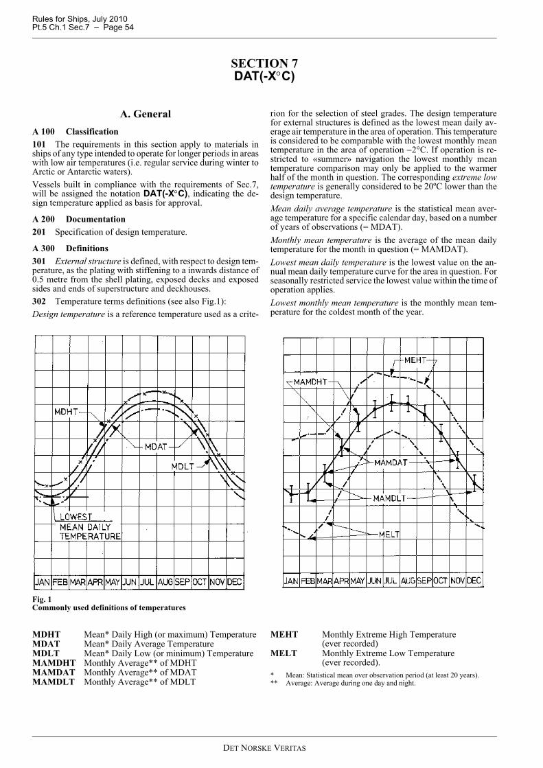
Rules for Ships, July 2010Pt.5 Ch.1 Sec.7 – Page 54
SECTION 7 DAT(-X°C)
A. GeneralA 100 Classification101 The requirements in this section apply to materials inships of any type intended to operate for longer periods in areaswith low air temperatures (i.e. regular service during winter toArctic or Antarctic waters).Vessels built in compliance with the requirements of Sec.7,will be assigned the notation DAT(-X°C), indicating the de-sign temperature applied as basis for approval.
A 200 Documentation201 Specification of design temperature.
A 300 Definitions301 External structure is defined, with respect to design tem-perature, as the plating with stiffening to a inwards distance of0.5 metre from the shell plating, exposed decks and exposedsides and ends of superstructure and deckhouses.302 Temperature terms definitions (see also Fig.1): Design temperature is a reference temperature used as a crite-
rion for the selection of steel grades. The design temperaturefor external structures is defined as the lowest mean daily av-erage air temperature in the area of operation. This temperatureis considered to be comparable with the lowest monthly meantemperature in the area of operation −2°C. If operation is re-stricted to «summer» navigation the lowest monthly meantemperature comparison may only be applied to the warmerhalf of the month in question. The corresponding extreme lowtemperature is generally considered to be 20ºC lower than thedesign temperature.Mean daily average temperature is the statistical mean aver-age temperature for a specific calendar day, based on a numberof years of observations (= MDAT). Monthly mean temperature is the average of the mean dailytemperature for the month in question (= MAMDAT). Lowest mean daily temperature is the lowest value on the an-nual mean daily temperature curve for the area in question. Forseasonally restricted service the lowest value within the time ofoperation applies. Lowest monthly mean temperature is the monthly mean tem-perature for the coldest month of the year.
Fig. 1Commonly used definitions of temperatures
MDHT Mean* Daily High (or maximum) Temperature MDAT Mean* Daily Average Temperature MDLT Mean* Daily Low (or minimum) Temperature MAMDHT Monthly Average** of MDHT MAMDAT Monthly Average** of MDAT MAMDLT Monthly Average** of MDLT
MEHT Monthly Extreme High Temperature (ever recorded)
MELT Monthly Extreme Low Temperature (ever recorded).
* Mean: Statistical mean over observation period (at least 20 years). ** Average: Average during one day and night.
DET NORSKE VERITAS
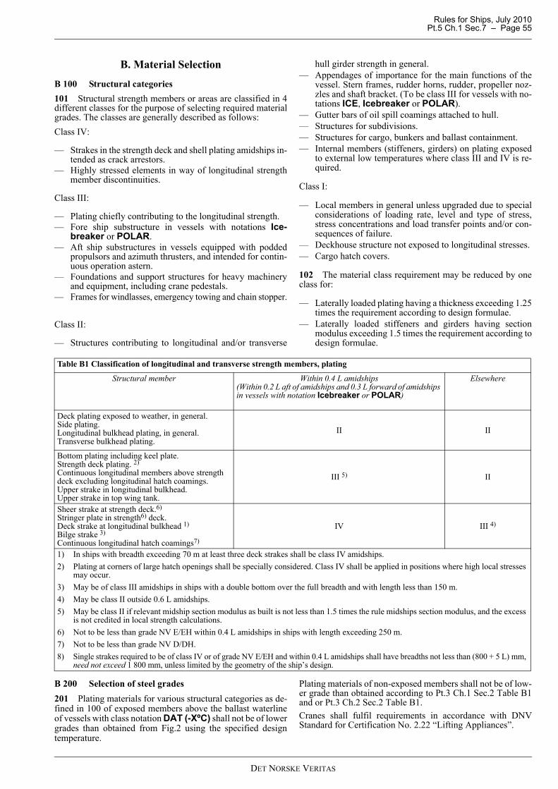
Rules for Ships, July 2010 Pt.5 Ch.1 Sec.7 – Page 55
B. Material Selection
B 100 Structural categories101 Structural strength members or areas are classified in 4different classes for the purpose of selecting required materialgrades. The classes are generally described as follows: Class IV:
— Strakes in the strength deck and shell plating amidships in-tended as crack arrestors.
— Highly stressed elements in way of longitudinal strengthmember discontinuities.
Class III:
— Plating chiefly contributing to the longitudinal strength. — Fore ship substructure in vessels with notations Ice-
breaker or POLAR.— Aft ship substructures in vessels equipped with podded
propulsors and azimuth thrusters, and intended for contin-uous operation astern.
— Foundations and support structures for heavy machineryand equipment, including crane pedestals.
— Frames for windlasses, emergency towing and chain stopper.
Class II:
— Structures contributing to longitudinal and/or transverse
hull girder strength in general. — Appendages of importance for the main functions of the
vessel. Stern frames, rudder horns, rudder, propeller noz-zles and shaft bracket. (To be class III for vessels with no-tations ICE, Icebreaker or POLAR).
— Gutter bars of oil spill coamings attached to hull.— Structures for subdivisions. — Structures for cargo, bunkers and ballast containment. — Internal members (stiffeners, girders) on plating exposed
to external low temperatures where class III and IV is re-quired.
Class I:
— Local members in general unless upgraded due to specialconsiderations of loading rate, level and type of stress,stress concentrations and load transfer points and/or con-sequences of failure.
— Deckhouse structure not exposed to longitudinal stresses.— Cargo hatch covers.
102 The material class requirement may be reduced by oneclass for:
— Laterally loaded plating having a thickness exceeding 1.25times the requirement according to design formulae.
— Laterally loaded stiffeners and girders having sectionmodulus exceeding 1.5 times the requirement according todesign formulae.
B 200 Selection of steel grades201 Plating materials for various structural categories as de-fined in 100 of exposed members above the ballast waterlineof vessels with class notation DAT (-XºC) shall not be of lowergrades than obtained from Fig.2 using the specified designtemperature.
Plating materials of non-exposed members shall not be of low-er grade than obtained according to Pt.3 Ch.1 Sec.2 Table B1and or Pt.3 Ch.2 Sec.2 Table B1.Cranes shall fulfil requirements in accordance with DNVStandard for Certification No. 2.22 “Lifting Appliances”.
Table B1 Classification of longitudinal and transverse strength members, plating
Structural member Within 0.4 L amidships(Within 0.2 L aft of amidships and 0.3 L forward of amidships in vessels with notation Icebreaker or POLAR)
Elsewhere
Deck plating exposed to weather, in general.Side plating.Longitudinal bulkhead plating, in general.Transverse bulkhead plating.
II II
Bottom plating including keel plate. Strength deck plating. 2) Continuous longitudinal members above strength deck excluding longitudinal hatch coamings.Upper strake in longitudinal bulkhead.Upper strake in top wing tank.
III 5) II
Sheer strake at strength deck.6)Stringer plate in strength6) deck.Deck strake at longitudinal bulkhead 1) Bilge strake 3) Continuous longitudinal hatch coamings7)
IV III 4)
1) In ships with breadth exceeding 70 m at least three deck strakes shall be class IV amidships. 2) Plating at corners of large hatch openings shall be specially considered. Class IV shall be applied in positions where high local stresses
may occur. 3) May be of class III amidships in ships with a double bottom over the full breadth and with length less than 150 m. 4) May be class II outside 0.6 L amidships. 5) May be class II if relevant midship section modulus as built is not less than 1.5 times the rule midships section modulus, and the excess
is not credited in local strength calculations. 6) Not to be less than grade NV E/EH within 0.4 L amidships in ships with length exceeding 250 m. 7) Not to be less than grade NV D/DH.8) Single strakes required to be of class IV or of grade NV E/EH and within 0.4 L amidships shall have breadths not less than (800 + 5 L) mm,
need not exceed 1 800 mm, unless limited by the geometry of the ship’s design.
DET NORSKE VERITAS

Rules for Ships, July 2010Pt.5 Ch.1 Sec.7 – Page 56
Fig. 2Required steel grades
Guidance note:When the structural category is known the material grade can beselected based on the design temperature and plate thickness.E.g. if a 30 mm plate should be applied for structural category IIIwith a design temperature of –30oC, grade E or EH need to be ap-plied. Boundary lines form part of the lower grade.
---e-n-d---of---G-u-i-d-a-n-c-e---n-o-t-e---
202 Forged or cast materials in structural members subject tolower design temperatures than −10°C according to B100 shallbe impact tested at 5°C below the design temperature.
100 90 80 70 60 FH 50 40 30 20
Thi
ckne
ss (m
m) →
10 Steel grade → E/EH D/DH B/AH A
-50 -40 -30 -20 -10 0 Class IV (Special)
-50 -40 -30 -20 -10 0 Class III (Primary)
-50 -40 -30 -20 -10 0 Class II (Secondary) Class I -50 -40 -30 -20 -10 0 ST
RU
CT
UR
AL
C
AT
EG
OR
IES
Design temperature (oC) →
DET NORSKE VERITAS

Rules for Ships, July 2010 Pt.5 Ch.1 Sec.8 – Page 57
SECTION 8 POLAR CLASS
A. General
A 100 Application 101 The requirements in this section are in general equiva-lent to the IACS Unified Requirements for Polar Ships (URI1to URI3), which apply to ships constructed of steel and intend-ed for navigation in ice-infested polar waters. 102 The rules consider hull structure, main propulsion, steer-ing gear, emergency and essential auxiliary systems essentialfor the safety of the ship and the survivability of the crew.
Guidance note:These rules do not consider aspects related to the operation of on-board equipment in cold climate. It is recommended that vesselsintended to operate in cold climate environments for longer peri-ods comply with the requirements as given in Sec.6,Winterization
---e-n-d---of---G-u-i-d-a-n-c-e---n-o-t-e---
103 Ships that comply with the requirements of Section 8can be considered for a Polar Class notation as listed in TableA1. If the hull and machinery are constructed such as to com-ply with the requirements of different polar classes, then theship shall be assigned the lower of these classes in the classifi-cation certificate. Compliance of the hull or machinery withthe requirements of a higher polar class is also to be indicatedin the classification certificate or an appendix thereto.104 Ships designed for ice breaking for the purpose of escortand ice management, and which are assigned a polar class no-tation PC-1 – PC-6, may be given the additional notation Ice-breaker.
A 200 Polar classes201 The Polar Class (PC) notations and descriptions are giv-en in Table A1. It is the responsibility of the owner to select anappropriate Polar Class. The descriptions in Table A1 are in-tended to guide owners, designers and administrations in se-lecting an appropriate Polar Class to match the requirementsfor the ship with its intended voyage or service.202 The Polar Class notation is used throughout the IACSUnified Requirements for Polar Ships to convey the differenc-es between classes with respect to operational capability andstrength.
A 300 Documentation301 UIWL and LIWL, as defined in Sec.1, shall be indicated
on the shell expansion plan together with the lines separatingthe various hull areas (ref. A500). The ship displacement atUIWL shall also be stated.302 Applicable design specifications for the operation of thevessel in ice infested waters shall be stated in the ship’s loadingmanual, see Pt.3 Ch.1 Sec.5 F and Pt.3 Ch.2 Sec.4 E. Possibledesign specifications are:
— UIWL and LIWL — loading conditions with respect to strength and stability— design speed— ramming speed— instruction for filling of ballast tanks— astern operation in ice— design temperature.
Guidance note:The design temperature reflects the lowest mean daily averageair temperature in the intended area of operation. An extreme airtemperature about 20°C below this may be tolerable to the struc-tures and equipment from a material point of view. For calcula-tions where the most extreme temperature over the day isrelevant, the air temperature can be set 20°C lower than the de-sign temperature in the notation. If no specification of the design temperature has been given, thevalues -35ºC for notations PC-1 to PC-5 and -25ºC for notationsPC-6 and PC-7 will be considered.
---e-n-d---of---G-u-i-d-a-n-c-e---n-o-t-e---
303 Details of the environmental conditions and the requiredice class for the machinery, if different from ship’s ice class.304 Detailed drawings of the main propulsion machinery.Description of the main propulsion, steering, emergency andessential auxiliaries shall include operational limitations. In-formation on essential main propulsion load control functions. 305 Description detailing how main, emergency and auxilia-ry systems are located and protected to prevent problems fromfreezing, ice and snow and evidence of their capability to op-erate in intended environmental conditions. 306 Calculations and documentation indicating compliancewith the requirements in subsections I and J. 307 For ships with class notation PC-6 or PC-7, informationwhether equivalency with notation 1A Super or 1A (DNV:ICE-1A* or ICE-1A) is requested, if applicable.
Guidance note:
---e-n-d---of---G-u-i-d-a-n-c-e---n-o-t-e---
A 400 Ship design and arrangement401 When the notation Icebreaker has been specified, thepowering and the bow form shall be such that the ship canbreak the typical level ice condition, as defined in Table A1 forthe specified Polar Class, effectively and at continuous speed.
Table A1 - Polar Class Descriptions
Polar Class Ice Description (based on WMO Sea Ice Nomenclature)
PC-1 Year-round operation in all Polar waters
PC-2 Year-round operation in moderate multi-year ice conditions
PC-3 Year-round operation in second-year ice which may include multi-year ice inclusions.
PC-4 Year-round operation in thick first-year ice which may include old ice inclusions
PC-5 Year-round operation in medium first-year ice which may include old ice inclusions
PC-6 Summer/autumn operation in medium first-year ice which may include old ice inclusions
PC-7 Summer/autumn operation in thin first-year ice which may include old ice inclusions
DNV Ice Class notation Equivalent Finnish-Swedish ice classPC-6 1) 1A SuperPC-7 1) 1A
1) The equivalence may be granted provided that the engine output of the ship complies with the requirements of chap-ter 3 in the FMA Ice Class Rules, 2002 (20.9.2002 No. 5/30/2002, FMA Bulletin 13/1.10.1002).
DET NORSKE VERITAS
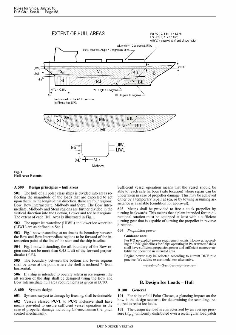
Rules for Ships, July 2010Pt.5 Ch.1 Sec.8 – Page 58
Fig. 1Hull Area Extents
A 500 Design principles – hull areas501 The hull of all polar class ships is divided into areas re-flecting the magnitude of the loads that are expected to actupon them. In the longitudinal direction, there are four regions:Bow, Bow Intermediate, Midbody and Stern. The Bow Inter-mediate, Midbody and Stern regions are further divided in thevertical direction into the Bottom, Lower and Ice belt regions.The extent of each Hull Area is illustrated in Fig.1.502 The upper ice waterline (UIWL) and lower ice waterline(LIWL) are as defined in Sec.1.503 Fig.1 notwithstanding, at no time is the boundary betweenthe Bow and Bow Intermediate regions to be forward of the in-tersection point of the line of the stem and the ship baseline.504 Fig.1 notwithstanding, the aft boundary of the Bow re-gion need not be more than 0.45 L aft of the forward perpen-dicular (F.P.).505 The boundary between the bottom and lower regionsshall be taken at the point where the shell is inclined 7° fromhorizontal.506 If a ship is intended to operate astern in ice regions, theaft section of the ship shall be designed using the Bow andBow Intermediate hull area requirements as given in B700.
A 600 System design 601 Systems, subject to damage by freezing, shall be drainable.602 Vessels classed PC-1, to PC-5 inclusive shall havemeans provided to ensure sufficient vessel operation in thecase of propeller damage including CP-mechanism (i.e. pitchcontrol mechanism).
Sufficient vessel operation means that the vessel should beable to reach safe harbour (safe location) where repair can beundertaken in case of propeller damage. This may be achievedeither by a temporary repair at sea, or by towing assuming as-sistance is available (condition for approval).603 Means shall be provided to free a stuck propeller byturning backwards. This means that a plant intended for unidi-rectional rotation must be equipped at least with a sufficientturning gear that is capable of turning the propeller in reversedirection.604 Propulsion power
Guidance note:For PC no explicit power requirement exists. However, accord-ing to "IMO guidelines for Ships operating in Polar waters" shipsshall have sufficient propulsion power and sufficient manoeuvra-bility for operation in intended area. Engine power may be selected according to current DNV rulepractice. We advise to use model test alternative.
---e-n-d---of---G-u-i-d-a-n-c-e---n-o-t-e---
B. Design Ice Loads – HullB 100 General101 For ships of all Polar Classes, a glancing impact on thebow is the design scenario for determining the scantlings re-quired to resist ice loads.102 The design ice load is characterized by an average pres-sure (Pavg) uniformly distributed over a rectangular load patch
DET NORSKE VERITAS

Rules for Ships, July 2010 Pt.5 Ch.1 Sec.8 – Page 59
of height (b) and width (w). 103 Within the Bow area of all polar classes, and within theBow Intermediate Ice belt area of polar classes PC-6 and PC-7, the ice load parameters are functions of the actual bowshape. To determine the ice load parameters (Pavg, b and w), itis required to calculate the following ice load characteristicsfor sub-regions of the bow area; shape coefficient (fai), totalglancing impact force (Fi), line load (Qi) and pressure (Pi).104 In other ice-strengthened areas, the ice load parameters(Pavg, bNonBow and wNonBow) are determined independently ofthe hull shape and based on a fixed load patch aspect ratio, AR = 3.6. 105 Design ice forces, calculated according to B, are in gen-eral considered valid for bow forms where the buttock angle,γ, is less than 80 degrees and the frame angle, β, is positive, seeFig.2. Design ice forces for other bow forms and for bow formsthat are otherwise considered to be non icebreaking will bespecially considered.106 Ship structures that are not directly subjected to ice loadsmay still experience inertial loads of stowed cargo and equip-ment resulting from ship/ice interaction, as given in 107 – 109,which shall be considered as alternative to the design acceler-ations given in Pt.3 Ch.1 Sec.4. 107 Maximum longitudinal impact acceleration at any pointalong the hull girder,
108 Combined vertical impact acceleration at any pointalong the hull girder,
Fx = 1.3 at F.P.= 0.2 at midships= 0.4 at A.P.= 1.3 at A.P. for vessels conducting ice breaking astern.
Intermediate values to be interpolated linearly.109 Combined transverse impact acceleration at any pointalong hull girder,
Fx = 1.5 at F.P.= 0.25 at midships= 0.5 at A.P.= 1.5 at A.P. for vessels conducting ice breaking astern.
Intermediate values to be interpolated linearly.where
φ = maximum friction angle between steel and ice, normal-ly taken as 10°[deg]
γ = bow stem angle at waterline [deg]Δtk = displacement at UIWL [kt]H = vertical distance from UIWL to the point being consid-
ered [m]FIB = vertical impact force, defined in D200FBow= as defined in B501.
B 200 Glancing impact load characteristics201 The parameters defining the glancing impact load char-acteristics are reflected in the Class Factors listed in Table B1.
B 300 Bow area301 In the Bow area, the force (F), line load (Q), pressure (P)and load patch aspect ratio (AR) associated with the glancing
impact load scenario are functions of the hull angles measuredat the upper ice waterline (UIWL). The influence of the hullangles is captured through calculation of a bow shape coeffi-cient (fa). The hull angles are defined in Fig.2.
Fig. 2Definition of hull angles
[ ]2m/s7)tan(1.1 ⎟⎠⎞
⎜⎝⎛ ++⎟⎟
⎠
⎞⎜⎜⎝
⎛Δ
=LHFa
tk
IBl φγ
[ ]2m/sxtk
IBv FFa ⎟⎟
⎠
⎞⎜⎜⎝
⎛Δ
=
tk
xBowt
FFa
Δ= 3
Table B1 - Class FactorsPolar Class
Crushing Failure Class Factor (CFC)
Flexural FailureClass Factor (CFF)
Load Patch DimensionsClass Factor (CFD)
DisplacementClass Factor (CFDIS)
Longitudinal StrengthClass Factor (CFL)
PC-1 17.69 68.60 2.01 250 7.46PC-2 9.89 46.80 1.75 210 5.46PC-3 6.06 21.17 1.53 180 4.17PC-4 4.50 13.48 1.42 130 3.15PC-5 3.10 9.00 1.31 70 2.50PC-6 2.40 5.49 1.17 40 2.37PC-7 1.80 4.06 1.11 22 1.81
DET NORSKE VERITAS

Rules for Ships, July 2010Pt.5 Ch.1 Sec.8 – Page 60
β’ = normal frame angle at upper ice waterline [deg]α = upper ice waterline angle [deg]γ = buttock angle at upper ice waterline (angle of but-
tock line measured from horizontal) [deg]tan(β) = tan(α)/tan(γ)tan(β’)= tan(β) cos(α).
302 The waterline length of the bow region is generally to bedivided into 4 sub-regions of equal length. The force (F), lineload (Q), pressure (P) and load patch aspect ratio (AR) shall becalculated with respect to the mid-length position of each sub-region (each maximum of F, Q and P shall be used in the cal-culation of the ice load parameters Pavg, b and w).303 The bow area load characteristics are determined as fol-lows:
a) Shape coefficient, fai, shall be taken as
fai = minimum (fai,1 ; fai,2 ; fai,3)where
b) Force, F:
Fi = fai ·CFC·Δtk0.64 [MN]
where
c) Load patch aspect ratio, AR:
ARi= 7.46·sin (β’i) ≥ 1.3where
d) Line load, Q:
Qi = Fi 0.61·CFD / ARi0.35 [MN/m]
where
e) Pressure, P:
Pi = Fi0.22·CFD
2·ARi0.3 [MPa]
where
B 400 Hull areas other than the bow401 In the hull areas other than the bow, the force (FNonBow)and line load (QNonBow) used in the determination of the loadpatch dimensions (bNonBow, wNonBow) and design pressure(Pavg) are determined as follows:
a) Force, FNonBow:
b) Line Load, QNonBow:
B 500 Design load patch501 In the Bow area, and the Bow Intermediate Ice belt areafor ships with class notation PC-6 and PC-7, the design loadpatch has dimensions of width, wBow, and height, bBow, de-fined as follows:
wBow = FBow / QBow [m]bBow = QBow / PBow [m]
where
FBow = maximum Fi in the Bow area [MN]QBow = maximum Qi in the Bow area [MN/m]PBow = maximum Pi in the Bow area [MPa]
502 In hull areas other than those covered by B501, the de-sign load patch has dimensions of width, wNonBow, and height,bNonBow, defined as follows:
fai,1 = (0.097 - 0.68 (x/Lwl - 0.15)2)·αi / (β’i)0.5
fai,2 = 1.2·CFF / (sin (β’i)·CFC·Δtk0.64)
fai,3 = 0.60i = sub-region consideredLwl = ship length measured at the upper ice
waterline (UIWL) [m]x = distance from the forward perpendicular
(FP) to station under consideration [m]α = waterline angle [deg], see Fig.2β’ = normal frame angle [deg], see Fig.2Δtk = ship displacement [kt] at UIWL, not to be
taken less than 5 ktCFC = Crushing Failure Class Factor from
Table B1CFF = Flexural Failure Class Factor from
Table B1
i = sub-region consideredfai = shape coefficient of sub-region iCFC = Crushing Failure Class Factor from
Table B1Δtk = ship displacement [kt] at UIWL, not to be
taken less than 5 kt
i = sub-region consideredβ’ = normal frame angle of sub-region i [deg]
i = sub-region consideredFi = force of sub-region i [MN]CFD = Load Patch Dimensions Class Factor
from Table B1
ARi = load patch aspect ratio of sub-region i
i = sub-region consideredFi = force of sub-region i [MN]CFD = Load Patch Dimensions Class Factor
from Table B1ARi = load patch aspect ratio of sub-region i
FNonBow = 0.36·CFC·DF [MN]
where
CFC = Crushing Force Class Factor from Table B1
CFD = Load Patch Dimensions Class Factor from Table B1
DF = ship displacement factor= Δtk
0.64 if Δtk ≤ CFDIS= CFDIS
0.64 + 0.10 (Δtk - CFDIS) if Δtk > CFDIS
Δtk = ship displacement [kt] at UIWL, not to be taken less than 10 kt
CFDIS = Displacement Class Factor from Table B1
QNonBow = 0.639·FNonBow0.61·CFD [MN/m]
where
FNonBow = force from (a) [MN]CFD = Load Patch Dimensions Class Factor
from Table B1.
DET NORSKE VERITAS
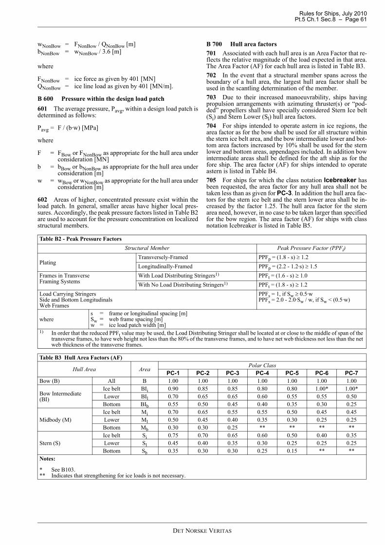
Rules for Ships, July 2010 Pt.5 Ch.1 Sec.8 – Page 61
wNonBow = FNonBow / QNonBow [m]bNonBow = wNonBow / 3.6 [m]
where
FNonBow = ice force as given by 401 [MN]QNonBow = ice line load as given by 401 [MN/m].
B 600 Pressure within the design load patch601 The average pressure, Pavg, within a design load patch isdetermined as follows:
Pavg = F / (b·w) [MPa]
where
F = FBow or FNonBow as appropriate for the hull area underconsideration [MN]
b = bBow or bNonBow as appropriate for the hull area underconsideration [m]
w = wBow or wNonBow as appropriate for the hull area underconsideration [m]
602 Areas of higher, concentrated pressure exist within theload patch. In general, smaller areas have higher local pres-sures. Accordingly, the peak pressure factors listed in Table B2are used to account for the pressure concentration on localizedstructural members.
B 700 Hull area factors701 Associated with each hull area is an Area Factor that re-flects the relative magnitude of the load expected in that area.The Area Factor (AF) for each hull area is listed in Table B3.702 In the event that a structural member spans across theboundary of a hull area, the largest hull area factor shall beused in the scantling determination of the member.703 Due to their increased manoeuvrability, ships havingpropulsion arrangements with azimuting thruster(s) or “pod-ded” propellers shall have specially considered Stern Ice belt(Si) and Stern Lower (Sl) hull area factors.704 For ships intended to operate astern in ice regions, thearea factor as for the bow shall be used for all structure withinthe stern ice belt area, and the bow intermediate lower and bot-tom area factors increased by 10% shall be used for the sternlower and bottom areas, appendages included. In addition bowintermediate areas shall be defined for the aft ship as for thefore ship. The area factor (AF) for ships intended to operateastern is listed in Table B4. 705 For ships for which the class notation Icebreaker hasbeen requested, the area factor for any hull area shall not betaken less than as given for PC-3. In addition the hull area fac-tors for the stern ice belt and the stern lower area shall be in-creased by the factor 1.25. The hull area factor for the sternarea need, however, in no case to be taken larger than specifiedfor the bow region. The area factor (AF) for ships with classnotation Icebreaker is listed in Table B5.
Table B2 - Peak Pressure FactorsStructural Member Peak Pressure Factor (PPFi)
PlatingTransversely-Framed PPFp = (1.8 - s) ≥ 1.2Longitudinally-Framed PPFp = (2.2 - 1.2·s) ≥ 1.5
Frames in TransverseFraming Systems
With Load Distributing Stringers1) PPFt = (1.6 - s) ≥ 1.0With No Load Distributing Stringers1) PPFt = (1.8 - s) ≥ 1.2
Load Carrying StringersSide and Bottom LongitudinalsWeb Frames
PPFs = 1, if Sw ≥ 0.5·wPPFs = 2.0 - 2.0·Sw / w, if Sw < (0.5·w)
where s = frame or longitudinal spacing [m]Sw = web frame spacing [m]w = ice load patch width [m]
1) In order that the reduced PPFt value may be used, the Load Distributing Stringer shall be located at or close to the middle of span of the transverse frames, to have web height not less than the 80% of the transverse frames, and to have net web thickness not less than the net web thickness of the transverse frames.
Table B3 Hull Area Factors (AF)
Hull Area AreaPolar Class
PC-1 PC-2 PC-3 PC-4 PC-5 PC-6 PC-7Bow (B) All B 1.00 1.00 1.00 1.00 1.00 1.00 1.00
Bow Intermediate (BI)
Ice belt BIi 0.90 0.85 0.85 0.80 0.80 1.00* 1.00*Lower BIl 0.70 0.65 0.65 0.60 0.55 0.55 0.50Bottom BIb 0.55 0.50 0.45 0.40 0.35 0.30 0.25
Midbody (M)Ice belt Mi 0.70 0.65 0.55 0.55 0.50 0.45 0.45Lower Ml 0.50 0.45 0.40 0.35 0.30 0.25 0.25Bottom Mb 0.30 0.30 0.25 ** ** ** **
Stern (S)Ice belt Si 0.75 0.70 0.65 0.60 0.50 0.40 0.35Lower Sl 0.45 0.40 0.35 0.30 0.25 0.25 0.25Bottom Sb 0.35 0.30 0.30 0.25 0.15 ** **
Notes:
* See B103.** Indicates that strengthening for ice loads is not necessary.
DET NORSKE VERITAS

Rules for Ships, July 2010Pt.5 Ch.1 Sec.8 – Page 62
C. Local Strength RequirementsC 100 Shell plate requirements101 The required minimum shell plate thickness, t, is givenby:t = tnet + ts [mm]where
tnet = plate thickness required to resist ice loads according toC102 [mm]
ts = corrosion and abrasion allowance according to H100[mm]
102 The thickness of shell plating required to resist the de-sign ice load, tnet, depends on the orientation of the framing.In the case of transversely-framed plating (Ω ≥ 70 deg), includ-ing all bottom plating, i.e. plating in hull areas BIb, Mb and Sb,the net thickness is given by:
In the case of longitudinally-framed plating (Ω ≤ 20 deg),when b ≥ s, the net thickness is given by:
In the case of longitudinally-framed plating (Ω ≤ 20 deg),when b < s, the net thickness is given by:
In the case of obliquely-framed plating (70 deg > Ω > 20 deg),linear interpolation shall be used.
Table B4 Hull Area Factors (AF) for ships intended to operate astern
Hull Area AreaPolar Class
PC-1 PC-2 PC-3 PC-4 PC-5 PC-6 PC-7Bow (B) All B 1.00 1.00 1.00 1.00 1.00 1.00 1.00
Bow Intermediate (BI)
Icebelt BIi 0.90 0.85 0.85 0.80 0.80 1.00* 1.00*Lower BIl 0.70 0.65 0.65 0.60 0.55 0.55 0.50Bottom BIb 0.55 0.50 0.45 0.40 0.35 0.30 0.25
Midbody (M)Icebelt Mi 0.70 0.65 0.55 0.55 0.50 0.45 0.45Lower Ml 0.50 0.45 0.40 0.35 0.30 0.25 0.25Bottom Mb 0.30 0.30 0.25 ** ** ** **
Stern Intermediate (SI)***
Icebelt SIi 0.90 0.85 0.85 0.80 0.80 1.00* 1.00*Lower SIl 0.70 0.65 0.65 0.60 0.55 0.55 0.50Bottom SIb 0.55 0.50 0.45 0.40 0.35 0.30 0.25
Stern (S)Icebelt Si 1.00 1.00 1.00 1.00 1.00 1.00 1.00Lower Sl 0.77 0.72 0.72 0.66 0.61 0.61 0.55Bottom Sb 0.61 0.55 0.50 0.44 0.39 0.33 0.28
Notes:
* See B103.** Indicates that strengthening for ice loads is not necessary.*** The Stern intermediate region, if any, for vessels intended to operate astern is to be defied as the region forward of Stern region to section
0.04 L forward of WL angle = 0 degrees at UIWL (ref. definition of Bow Intermediate in Fig.1).
Table B5 Hull Area Factors (AF) for ships with class notation Icebreaker
Hull Area AreaPolar Class
PC-1 PC-2 PC-3 PC-4 PC-5 PC-6 PC-7Bow (B) All B 1.00 1.00 1.00 1.00 1.00 1.00 1.00
Bow Intermediate (BI)
Icebelt BIi 0.90 0.85 0.85 0.85 0.85 1.00* 1.00*Lower BIl 0.70 0.65 0.65 0.65 0.65 0.65 0.65Bottom BIb 0.55 0.50 0.45 0.45 0.45 0.45 0.45
Midbody (M)Icebelt Mi 0.70 0.65 0.55 0.55 0.55 0.55 0.55Lower Ml 0.50 0.45 0.40 0.40 0.40 0.40 0.40Bottom Mb 0.30 0.30 0.25 0.25 0.25 0.25 0.25
Stern (S)Icebelt Si 0.94 0.88 0.81 0.81 0.81 0.81 0.81Lower Sl 0.56 0.50 0.44 0.44 0.44 0.44 0.44Bottom Sb 0.35 0.30 0.30 0.30 0.30 0.30 0.30
Notes:
* See B103.
( ) [ ]mm2/1
1500bs
PPPFAFst
F
avgpnet +
⋅⋅=
σ
( ) [ ]mm2/1
1500ls
PPPFAFst
F
avgpnet +
⋅⋅=
σ
( ) [ ]mm2/1
125002
lssb
sbPPPFAF
stF
avgpnet +
⎟⎠⎞
⎜⎝⎛−
⋅⋅=
σ
DET NORSKE VERITAS

Rules for Ships, July 2010 Pt.5 Ch.1 Sec.8 – Page 63
where:
Ω = smallest angle between the chord of the waterlineand the line of the first level framing as illustrated inFig.3 [deg]
s = transverse frame spacing in transversely-framedships or longitudinal frame spacing in longitudinal-ly-framed ships [m]
AF = Hull Area Factor from Table B3PPFp = Peak Pressure Factor from Table B2Pavg = average patch pressure as given in B600 [MPa]
σF = minimum upper yield stress of the material [N/mm2]
b = height of design load patch [m], where b ≤ (l – s/4)in the case of transversely framed plating
l = distance between frame supports, i.e. equal to theframe span as given in C205, but not reduced forany fitted end brackets [m]. When a load-distribut-ing stringer is fitted, the length l need not be takenlarger than the distance from the stringer to the mostdistant frame support.
Fig. 3Shell Framing Angle Ω
C 200 Framing general201 Framing members of Polar class ships shall be designedto withstand the ice loads defined in B.202 The term “framing member” refers to transverse andlongitudinal local frames, load-carrying stringers and webframes in the areas of the hull exposed to ice pressure, seeFig.1. 203 The strength of a framing member is dependent upon thefixity that is provided at its supports. Fixity can be assumedwhere framing members are either continuous through the sup-port or attached to a supporting section with a connectionbracket. In other cases, simple support should be assumed un-less the connection can be demonstrated to provide significantrotational restraint. Fixity shall be ensured at the support of anyframing which terminates within an ice-strengthened area.204 The details of framing member intersection with otherframing members, including plated structures, as well as thedetails for securing the ends of framing members at supportingsections, shall be in accordance with 900 and Pt.3 Ch.1 Sec.3 Cas applicable205 The design span of framing members shall generally bedetermined according to Pt.3 Ch.1 Sec.3 C100. However, thespan length is only to be reduced in accordance with Pt.3 Ch.1Sec.3 C100 provided the end brackets fitted are flanged or theedge length in mm is equal to or less than 600 tbn /σF
0.5. tbn = net thickness of bracket [mm]
σF = minimum upper yield stress of the material [N/mm2]206 Load-carrying stringers and web frames are generally tobe of symmetrical cross-section. When the flange is arrangedto be unsymmetrical, an effective tripping support shall be pro-vided at the middle of each span length.207 When calculating the section modulus and shear area ofa framing member, net thicknesses of the web, flange (if fitted)and of the attached shell plating shall be used. The shear areaof a framing member may include that material contained overthe full depth of the member, i.e. web area including portion offlange, if fitted, but excluding attached shell plating.208 The actual net effective shear area, Aw, of a framingmember is given by:
where
h = height of stiffener [mm], see Fig.4twn = net web thickness [mm]
= tw - tstw = as built web thickness [mm], see Fig.4ts = corrosion addition [mm], as given in H103, to be sub-
tracted from the web and flange thickness ϕw = smallest angle between shell plate and stiffener web,
measured at the midspan of the stiffener, see Fig.4. Theangle ϕw may be taken as 90 degrees provided thesmallest angle is not less than 75 degrees.
][cm100/sinthA 2wwnw ϕ=
DET NORSKE VERITAS

Rules for Ships, July 2010Pt.5 Ch.1 Sec.8 – Page 64
Fig. 4Stiffener geometry
209 When the cross-sectional area of the attached plateflange exceeds the cross-sectional area of the local frame, theactual net effective plastic section modulus, Zp, is given by:
h, twn, and ϕw are as given in C207 and s as given in C102.
Apn = net cross-sectional area of attached plate [cm2] (equalto tpn×s·10, but not to be taken greater than the netcross-sectional area of the local frame)
tpn = fitted net shell plate thickness [mm] (shall comply withtnet as required by C102)
hw = height of local frame web [mm], see Fig.4Afn = net cross-sectional area of local frame flange [cm2]hfc = height of local frame measured to centre of the flange
area [mm], see Fig.4bw = distance from mid thickness plane of local frame web
to the centre of the flange area [mm], see Fig.4.
When the cross-sectional area of the local frame exceeds thecross-sectional area of the attached plate flange, the plasticneutral axis is located a distance zna above the attached shellplate, given by:
and the net effective plastic section modulus, Zp, is given by:
210 In the case of oblique framing arrangement 70 deg > Ω > 20 deg, where Ω is defined as given in C102, lin-ear interpolation shall be used.
C 300 Framing – Transversely framed side structures and bottom structures301 The local frames in transversely-framed side structuresand in bottom structures (i.e. hull areas BIb, Mb and Sb) shallbe dimensioned such that the combined effects of shear andbending do not exceed the plastic strength of the member. Theplastic strength is defined by the magnitude of patch load thatcauses the development of a plastic hinge mechanism.
302 The actual net effective shear area of the frame, Aw, asdefined in C208, shall comply with the following condition: Aw ≥ At, where:
At = 1002·0.5·LL·s·(AF·PPFt·Pavg) / (0.577·σF) [cm2]where
LL = length of loaded portion of span = lesser of a and b [m]a = frame span as defined in C205 [m]b = height of design ice load patch as given in B500 [m]s = transverse frame spacing [m]AF = Hull Area Factor from Table B3PPFt = Peak Pressure Factor from Table B2Pavg = average pressure within load patch as given in B600
[MPa]σF = minimum upper yield stress of the material
[N/mm2]303 The actual net effective plastic section modulus of theplate/stiffener combination, Zp, as defined in C209, shall com-ply with the following condition: Zp ≥ Zpt, where Zpt shall bethe greater calculated on the basis of two load conditions: a) iceload acting at the midspan of the transverse frame, and b) theice load acting near a support. The A1 parameter reflects thetwo conditions:
Zpt = 1003·LL·Y·s·(AF·PPFt·Pavg)·a·A1 / (4·σF) [cm3]where:AF, PPFt, Pavg, LL, b, s, a and σF are as given in C302.
Y = 1 - 0.5·(LL / a)A1 = maximum of:
304 The scantlings of the frame shall meet the structural sta-bility requirements of C600.
[ ]3
2
cm10/)cossin(2000
sin20/
wwfcfn
wwnwpnpnp
hA
thtAZ
ϕϕ
ϕ
−
++=
( ) ( )wnpnwnwfnna tstthAz 2/1000100 −+= [mm]
( )( )
( )( ) ⎟⎟⎟
⎠
⎞
⎜⎜⎜
⎝
⎛
−−+
+−+=
10/cossin0002
sinsin
22
wwwnafcfn
wwnnanaw
wnapnp
bzhA
tzzhzstZ
ϕϕ
ϕϕ [cm3]
A1A = 1 / (1 + j / 2 + kw·j / 2·[(1 - a12) 0.5 - 1])
A1B = (1 – 1 / (2·a1·Y)) / (0.275 + 1.44·kz0.7)
j = 1 for framing with one simple support outside the ice-strengthened areas
= 2 for framing without any simple supportsa1 = At / Aw
At = minimum shear area of transverse frame as given in C302 [cm2]
Aw = effective net shear area of transverse frame (calculated according to C208 [cm2]
kw = 1 / (1 + 2·Afn / Aw) with Afn as given in C209kz = zp / Zp in general
0.0 when the frame is arranged with end bracketzp = sum of the individual plastic section modulus of
flange and shell plate as fitted [cm3]= (bf·tfn2 / 4 + beff·tpn
2 / 4) / 1000bf = flange breadth [mm], see Fig.4tfn = net flange thickness [mm]
= tf – ts (ts as given in C208)tf = as-built flange thickness [mm], see Fig.4tpn = the fitted net shell plate thickness [mm] (not to be
less than tnet as given in C102)beff = effective width of shell plate flange [mm]
= 500 sZp = net effective plastic section modulus of trans-
verse frame (calculated according to C209) [cm3].
DET NORSKE VERITAS

Rules for Ships, July 2010 Pt.5 Ch.1 Sec.8 – Page 65
C 400 Framing – Side longitudinals(longitudinally framed ships)401 Side longitudinals shall be dimensioned such that thecombined effects of shear and bending do not exceed the plas-tic strength of the member. The plastic strength is defined bythe magnitude of midspan load that causes the development ofa plastic collapse mechanism.402 The actual net effective shear area of the frame, Aw, asdefined in C208, shall comply with the following condition:
Aw ≥ ALwhere
AL = 1002·(AF·PPFs·Pavg)·0.5·b1·a / (0.577·σF) [cm2]where
AF = Hull Area Factor from Table B3PPFs = Peak Pressure Factor from Table B2Pavg = average pressure within load patch as given in B600
[MPa]b1 = ko·b2 [m]ko = 1 - 0.3 / b’b’ = b / sb = height of design ice load patch as given by B501/
B502 [m]s = spacing of longitudinal frames [m]b2 = b (1 - 0.25·b’) [m], if b’ < 2 = s [m], if b’ ≥ 2a = longitudinal design span as given in C205 [m]σF = minimum upper yield stress of the material
[N/mm2].403 The actual net effective plastic section modulus of theplate/stiffener combination, Zp, as defined in C209, shall com-ply with the following condition: Zp ≥ ZpL, where:ZpL = 1003·(AF·PPFs·Pavg)·b1·a2·A4 / (8·σF) [cm3]whereAF, PPFs, Pavg, b1, a and σF are as given in C402
A4 = 1 / (2 + kwl·[(1 - a42)0.5 - 1])
a4 = AL / AwAL = minimum shear area for longitudinal as given in C402
[cm2]Aw = net effective shear area of longitudinal (calculated ac-
cording to C208 [cm2]kwl = 1 / (1 + 2·Afn / Aw) with Afn as given in C209.
404 The scantlings of the longitudinals shall meet the struc-tural stability requirements of C600.
C 500 Framing – web frame and load carrying stringers501 Web frames and load-carrying stringers shall be de-signed to withstand the ice load patch as defined in B500. Theload patch shall be applied at locations where the capacity ofthese members under the combined effects of bending andshear is minimised.502 Where load carrying stringers or web frames supportinglocal frames constitute regular structures with sufficient andwell defined support capacity and boundary condition at endsupports, and with the stringer or web frame located within thehull area considered, see A500, the required effective net webarea and net section modulus is as given in 503 or 505. The re-quired shear area and section modulus of web frames support-ing load carrying stringers is as given in 504. Alternatively,and where web frames and load-carrying stringers form part ofa structural grillage system, appropriate methods of analysis asoutlined in F103 shall be used. 503 The effective net web area in cm2, as defined in Pt.3Ch.1 Sec.3 C500, of web frames supporting longitudinal local
frames, Awf, shall not be less than:
where
AF = Hull Area Factor from Table B3PPFs = Peak Pressure Factor from Table B2Pavg = average pressure within load patch as given in B601
[MPa]Ks = [S – (LHs + s)/2]/S, minimum 0.55LHs = load height with respect to shear response of web
frame, given as the smaller of b and (S-s) [m] LLs = load length with respect to shear response of web
frame = w (l – w/4)/l [m]l = spacing of web frames, measured along the shell
plate [m]b = height of design ice load patch as given by B501/
B502 [m]s = longitudinal frame spacing [m]S = span length of web frame as given in C205 [m]w = length of load patch as given in B601[m], but is not
to be taken larger than 2 l η = usage factor = 0.9σF = minimum upper yield stress of the material [N/
mm2]ϕw = smallest angle between shell plate and the web of
the web frame, measured at middle of span.The angle ϕw may be taken as 90 degrees providedthe smallest angle is not less than 75 degrees.
The net elastic section modulus in cm3 of web frames support-ing longitudinal local frames, Zwf, shall not be less than:
where
a = design span of local frames as given in 205 [m]LHb = load height w.r.t bending response of web frame,
given as the smaller of b and S [m]
kf = end fixity parameter for the web frame= 2.0 when both end supports are fixed
= 1.5 when one end support is fixed = 1.0 when both end supports are simply supportedkfl = end fixity parameter for the local frames = 2.0 when both end supports are fixed = 1.5 when one end support is fixed = 1.0 when both end supports are simply supportedZp = net plastic section modulus of fitted local ice frames
as given in 209.504 The effective net web area in cm2, as defined in Pt.3Ch.1 Sec.3 C500, of web frames supporting load carryingstringers, Awf, shall not be less than:
where
AF = Hull Area Factor from Table B3PPFs = Peak Pressure Factor from Table B2Pavg = average pressure within load patch as given in B601
[MPa]b = height of design ice load patch as given by B501/
B502 [m]
( )wF
sssavgswf
KLLLHPPPFAFA
ϕησ sin577.01002
= [cm2]
( ) ( )ask
SkZk
LHSLLLHPPPFAFZ
f
flp
fwF
bsbavgswf 16sin4
2/100 23
−−
=ϕσ
( ) ( )( ) ( )llS
blwlCSbwPPPFAFA
LCSwF
LCSavgswf ϕησ sin577.0
4/4/1002 −−−= [cm2]
DET NORSKE VERITAS

Rules for Ships, July 2010Pt.5 Ch.1 Sec.8 – Page 66
C = smallest distance from considered load carryingstringer to web frame support [m]
lLCS = distance between web frames, measured along theshell plate [m]
l = distance from considered load carrying stringer toadjacent load carrying stringer or longitudinal sup-port member, as applicable, measured along theshell plate [m]
S = span length of web frame as given in C205 [m] w = length of load patch as given in B601 [m]η = usage factor = 0.9σF = minimum upper yield stress of the material
[N/mm2]ϕw = smallest angle between shell plate and the web of the
web frame, measured at the load carrying stringer. The net elastic section modulus in cm3 of web frames support-ing load carrying stringer, Zwf, shall not be less than:
where
kf = end fixity parameter for the web frame= 2.0 when both end supports are fixed= 1.5 when one end support is fixed = 1.0 when both end supports are simply supported.
505 The effective net web area in cm2, as defined in Pt.3Ch.1 Sec.3 C500, of load-carrying stringers, Alcs, shall not beless than:
where
AF = Hull Area Factor from Table B3PPFs = Peak Pressure Factor from Table B2Pavg = average pressure within load patch, as given in
B601 [MPa]LHs = load height with respect to shear response of
stringer = b (l – b/4)/l [m] LLs = load length with respect to shear response of string-
er, given as the smaller of w and (S-s) [m] l = distance between transverse frame supports, meas-
ured along the shell plate [m]b = height of design ice load patch as given in B601[m]w = length of load patch as given in B601[m]s = spacing of transverse frames [m]S = span of stringer as given in C205 [m]η = usage factor = 0.9σF = minimum upper yield stress of the material
[N/mm2]ϕw = smallest angle between shell plate and the web of
the stringer, measured at middle of span. The angleϕw may be taken as 90 degrees provided the small-est angle is not less than 75 degrees.
The net elastic section modulus in cm3 of the stringer, Zlcs,shall not be less than:
where
a = design span of local frames as given in C205 [m]kf = end fixity parameter for the load-carrying stringer = 2.0 when both end supports are fixed
= 1.5 when one end support is fixed = 1.0 when both end supports are simply supportedkfl = end fixity parameter for the local frames = 2.0 when both end supports are fixed = 1.5 when one end support is fixed = 1.0 when both end supports are simply supportedLLb = load length w.r.t bending response of stringer, given
as the smaller of w and S [m] Zp = net plastic section modulus of fitted local ice frames
as given in 209506 The scantlings of web frames and load-carrying string-ers shall meet the structural stability requirements of C600.
C 600 Framing – Structural stability601 To prevent local buckling in the web, the ratio of webheight (hw) to net web thickness (twn) of any framing membershall not exceed:For flat bar sections:
hw / twn ≤ 282 / (σF)0.5
For bulb, tee and angle sections:hw / twn ≤ 805 / (σF)0.5
where
hw = web height twn = net web thicknessσF = minimum upper yield stress of the material [N/mm2].
602 Framing members for which it is not practicable to meetthe requirements of C601 (e.g. load carrying stringers or deepweb frames) are required to have their webs effectively stiff-ened. The scantlings of the web stiffeners shall ensure thestructural stability of the framing member. The minimum netweb thickness for these framing members is given by:
where
c1 = hw – 0.8·h [mm]hw = web height of stringer/web frame [mm] (see Fig.5)h = height of framing member penetrating the member un-
der consideration (0 if no such framing member) [mm](see Fig.5)
c2 = spacing between supporting structure oriented perpen-dicular to the member under consideration [mm] (seeFig.5)
σF = minimum upper yield stress of the material [N/mm2].
Fig. 5Parameter Definition for Web Stiffening
603 In addition, the following shall be satisfied:twn ≥ 0.35·tpn·(σF / 235)0.5
where
σF = minimum upper yield stress of the material [N/mm2]twn = net thickness of the web [mm]tpn = net thickness of the shell plate in way the framing
member [mm].
( ) ( )( )( ) [ ]33
cmsin2
4/14/100llSk
bwlCSCbwPPPFAFZ
LCSfwF
LCSavgswf ϕσ
−−−=
( ) ( )( ) [ ]3
wF
sssavgs2
lcs cmsinS577.0
2/sLLSLLLHPPPFAF100A
ϕησ
+−=
( ) ( )ask
SkZk
wSLLbPPPFAFZ
f
flp
fwF
Bavgslcs 16sin4
2/100 23
−−
=ϕσ
twn 2.63 10 3– c1 σF 5.34 4 c1 c2⁄( )2⋅+( )⁄( ) [mm]⋅ ⋅ ⋅=
DET NORSKE VERITAS

Rules for Ships, July 2010 Pt.5 Ch.1 Sec.8 – Page 67
604 To prevent local flange buckling of welded profiles, thefollowing shall be satisfied:
(i) The flange width, bf [mm], shall not be less than five timesthe net thickness of the web, twn.
(ii) The flange outstand, bout [mm], shall meet the followingrequirement:
bout / tfn ≤ 155 / (σF)0.5
where
tfn = net thickness of flange [mm]σF = minimum upper yield stress of the material [N/mm2]
C 700 Plated structures701 Plated structures are those stiffened plate elements incontact with the shell and subject to ice loads. These require-ments are applicable to an inboard extent which is the lesser of:
(i) web height of adjacent parallel web frame or stringer; or(ii) 2.5 times the depth of framing that intersects the plated
structure.702 The thickness of the plating and the scantlings of at-tached stiffeners shall be consistent with the end connection re-quirements for supported framing as given in C900. 703 Plated structures subjected to direct ice loads, as definedin B, shall be considered with respect to the buckling require-ments in Pt.3 Ch.1 Sec.13.
C 800 Stem and stern frames801 For PC-6/PC-7 vessels requiring 1A*/1A equivalency,the stem and stern requirements of the Finnish-Swedish IceClass Rules may need to be additionally considered. 802 When the vessel has a sharp edged stem, the thickness ofthe stem side plate within a breadth not less than 0.7 s, where sdenotes the spacing of stiffening members, shall not be lessthan 1.2 t, where t denotes the required net shell plate thicknessfor the bow area, as given in C100. 803 In vessels intended to operate under harsh ice condition,and of type and size that may cause excessive beaching to oc-cur, a forward ice knife may be required fitted. This require-ment will be based on consideration of design speed, stabilityand freeboard.
C 900 End Connections for framing members 901 The end connection for framing members exposed to iceloads, to supports, e.g. stringers, web frames, decks or bulk-heads, shall be related to the response of the member whensubjected to ice loads. The connection area is generally ob-tained through support members such as collar plate, lugs, endbrackets or web stiffener. The total net connection area of support members is given as:
where
hi = effective dimension of connection area of member #iti = thickness of connection area #ikt = 1.0 for members where critical stress response is shear
= 1.5 for members where critical stress response is nor-mal stress
n = number of support membersts = minimum corrosion addition as given in H103.
902 The net end connection area fitted, a, is generally not tobe less than ao, given as:
for longitudinal local frames
for transverse local frames
for load carrying stringers
for transverse web frames supporting longitudinal local frames
where
AF = Hull Area Factor from Table B3PPF = Peak Pressure Factor from Table B2Pavg = average pressure within load patch as given in B601
[MPa]LH = load height, given as the smaller of b and (a-s) [m] LL = load length, given as the smaller of w and (a-s) [m] a, S = span of member as given in C205 [m]s = spacing of frames (m) b, w = as given in B601b1 = as given in 402 η = usage factor = 0.9σF = minimum upper yield stress of the material [N/mm2]ϕw = smallest angle between shell plate and the web of the
stringer or web frame as applicable, measured at the in-tersection with the stiffener. The angle ϕw may be tak-en as 90 degrees provided the smallest angle is not lessthan 75 degrees.
903 For support members constituting the end connection,the throat thickness in mm of double fillet welds for the attach-ment of the support member i, to the framing member and thesupport is given as the smaller of:
= 0.5 ti
where
a = as given in 901ao = as given in 902ti = thickness of connection member i [mm]fw = as given in Pt.3 Ch.1 Sec.11 C103ts = corrosion addition/abrasion addition as given in H103.
D. Longitudinal StrengthD 100 Application101 Ice loads need only be combined with still water loads.The combined stresses shall be compared against permissiblebending and shear stresses at different locations along theship’s length. In addition, sufficient local buckling strength isalso to be verified.
[cm2]( ) in
si httk01.0a ∑ −= τ
( ) ( ) ( )wF
avgso a
waswbPPPFAFa
ϕησ sin577.02/100 1
2 −−= [cm2]
( ) ( )( )wF
avgto a
sbabsPPPFAFa
ϕησ sin577.02/1002 +−
= [cm2]
( ) ( ) ( )wF
avgso S
wSswbPPPFAFa
ϕησ sin577.02/1002 −−
= [cm2]
( ) ( )( )wF
avgso S
sbSbwPPPFAFa
ϕησ sin577.02/1002 +−
= [cm2]
( )s
w
Fociw t
faatt
t 5.0450
+−
=σ
DET NORSKE VERITAS
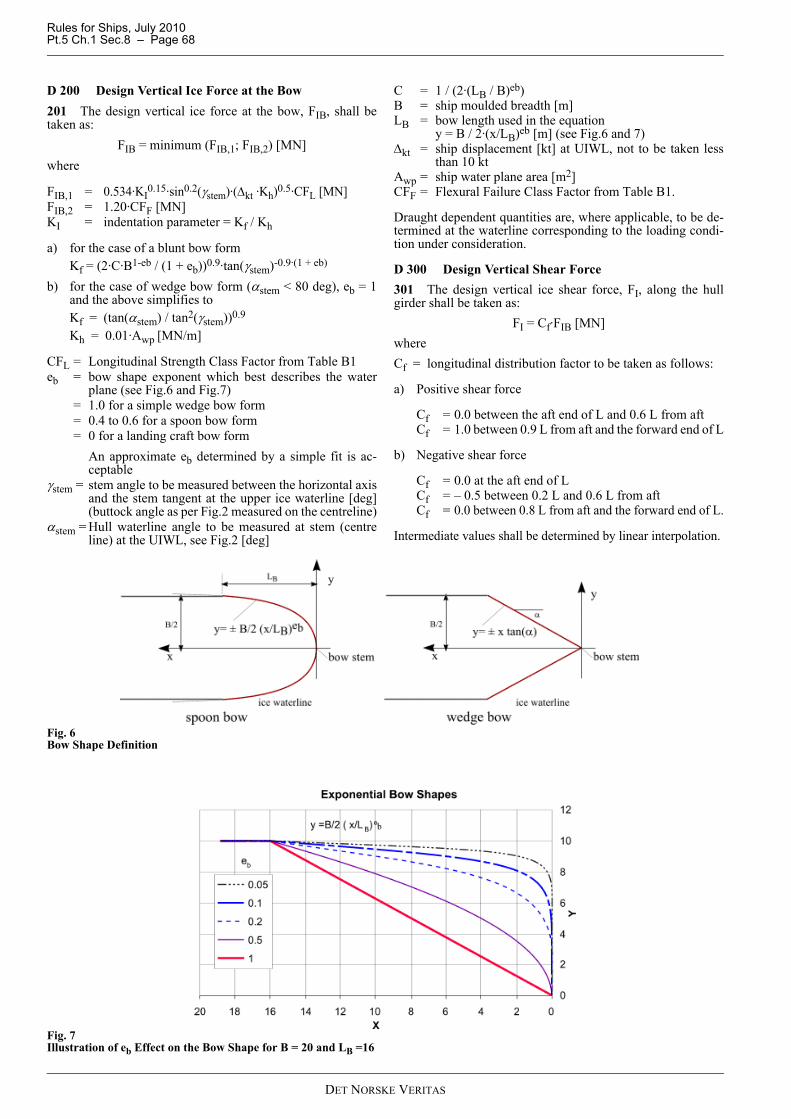
Rules for Ships, July 2010Pt.5 Ch.1 Sec.8 – Page 68
D 200 Design Vertical Ice Force at the Bow201 The design vertical ice force at the bow, FIB, shall betaken as:
FIB = minimum (FIB,1; FIB,2) [MN]where
FIB,1 = 0.534·KI0.15·sin0.2(γstem)·(Δkt ·Kh)0.5·CFL [MN]
FIB,2 = 1.20·CFF [MN]KI = indentation parameter = Kf / Kh
a) for the case of a blunt bow form Kf = (2·C·B1-eb / (1 + eb))0.9·tan(γstem)-0.9·(1 + eb)
b) for the case of wedge bow form (αstem < 80 deg), eb = 1and the above simplifies toKf = (tan(αstem) / tan2(γstem))0.9
Kh = 0.01·Awp [MN/m]
CFL = Longitudinal Strength Class Factor from Table B1eb = bow shape exponent which best describes the water
plane (see Fig.6 and Fig.7) = 1.0 for a simple wedge bow form = 0.4 to 0.6 for a spoon bow form = 0 for a landing craft bow form
An approximate eb determined by a simple fit is ac-ceptable
γstem = stem angle to be measured between the horizontal axisand the stem tangent at the upper ice waterline [deg](buttock angle as per Fig.2 measured on the centreline)
αstem = Hull waterline angle to be measured at stem (centreline) at the UIWL, see Fig.2 [deg]
C = 1 / (2·(LB / B)eb)B = ship moulded breadth [m]LB = bow length used in the equation
y = B / 2·(x/LB)eb [m] (see Fig.6 and 7)Δkt = ship displacement [kt] at UIWL, not to be taken less
than 10 ktAwp = ship water plane area [m2]CFF = Flexural Failure Class Factor from Table B1.
Draught dependent quantities are, where applicable, to be de-termined at the waterline corresponding to the loading condi-tion under consideration.
D 300 Design Vertical Shear Force301 The design vertical ice shear force, FI, along the hullgirder shall be taken as:
FI = Cf·FIB [MN]whereCf = longitudinal distribution factor to be taken as follows:
a) Positive shear force
Cf = 0.0 between the aft end of L and 0.6 L from aftCf = 1.0 between 0.9 L from aft and the forward end of L
b) Negative shear force
Cf = 0.0 at the aft end of LCf = – 0.5 between 0.2 L and 0.6 L from aftCf = 0.0 between 0.8 L from aft and the forward end of L.
Intermediate values shall be determined by linear interpolation.
Fig. 6Bow Shape Definition
Fig. 7Illustration of eb Effect on the Bow Shape for B = 20 and LB =16
DET NORSKE VERITAS
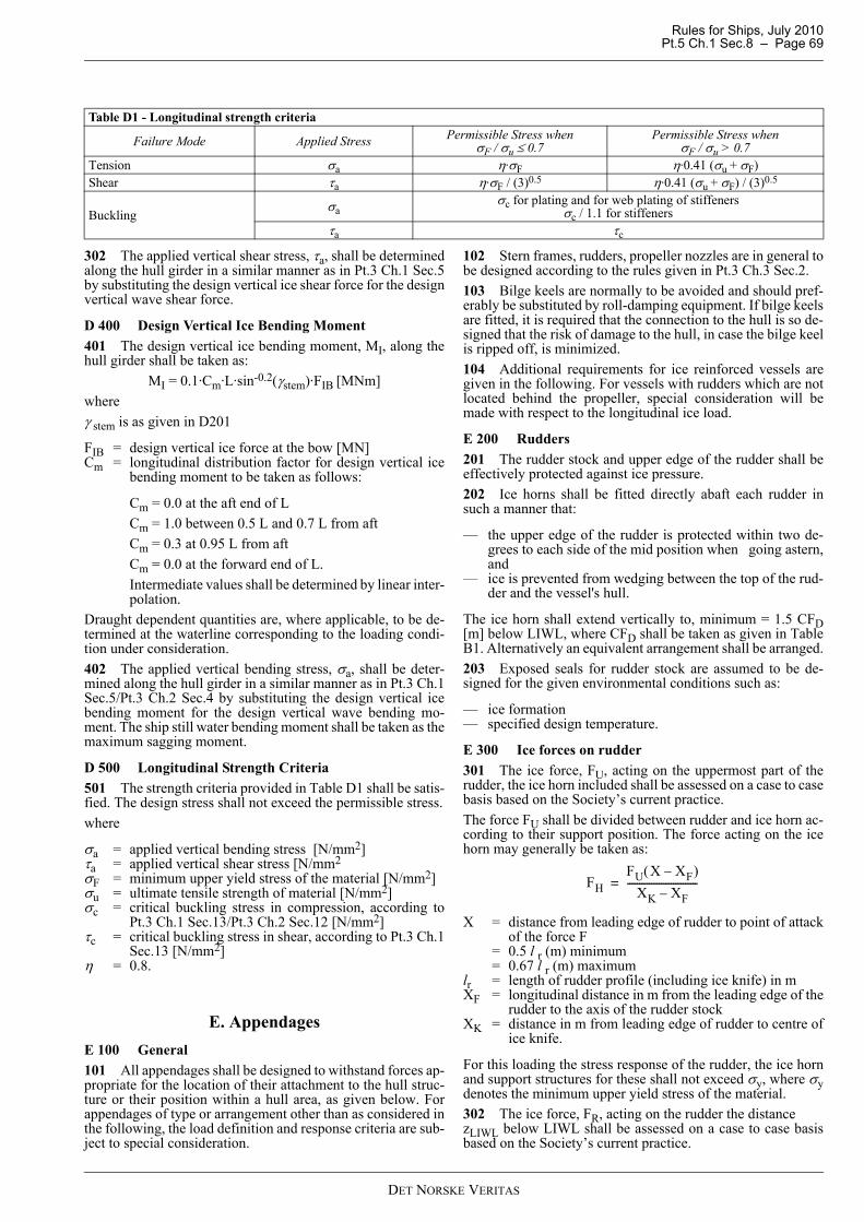
Rules for Ships, July 2010 Pt.5 Ch.1 Sec.8 – Page 69
302 The applied vertical shear stress, τa, shall be determinedalong the hull girder in a similar manner as in Pt.3 Ch.1 Sec.5by substituting the design vertical ice shear force for the designvertical wave shear force.
D 400 Design Vertical Ice Bending Moment 401 The design vertical ice bending moment, MI, along thehull girder shall be taken as:
MI = 0.1·Cm·L·sin-0.2(γstem)·FIB [MNm]whereγ stem is as given in D201
FIB = design vertical ice force at the bow [MN]Cm = longitudinal distribution factor for design vertical ice
bending moment to be taken as follows:
Cm = 0.0 at the aft end of LCm = 1.0 between 0.5 L and 0.7 L from aftCm = 0.3 at 0.95 L from aftCm = 0.0 at the forward end of L.Intermediate values shall be determined by linear inter-polation.
Draught dependent quantities are, where applicable, to be de-termined at the waterline corresponding to the loading condi-tion under consideration.402 The applied vertical bending stress, σa, shall be deter-mined along the hull girder in a similar manner as in Pt.3 Ch.1Sec.5/Pt.3 Ch.2 Sec.4 by substituting the design vertical icebending moment for the design vertical wave bending mo-ment. The ship still water bending moment shall be taken as themaximum sagging moment.
D 500 Longitudinal Strength Criteria501 The strength criteria provided in Table D1 shall be satis-fied. The design stress shall not exceed the permissible stress.where
σa = applied vertical bending stress [N/mm2]τa = applied vertical shear stress [N/mm2σF = minimum upper yield stress of the material [N/mm2]σu = ultimate tensile strength of material [N/mm2]σc = critical buckling stress in compression, according to
Pt.3 Ch.1 Sec.13/Pt.3 Ch.2 Sec.12 [N/mm2]τc = critical buckling stress in shear, according to Pt.3 Ch.1
Sec.13 [N/mm2]η = 0.8.
E. AppendagesE 100 General101 All appendages shall be designed to withstand forces ap-propriate for the location of their attachment to the hull struc-ture or their position within a hull area, as given below. Forappendages of type or arrangement other than as considered inthe following, the load definition and response criteria are sub-ject to special consideration.
102 Stern frames, rudders, propeller nozzles are in general tobe designed according to the rules given in Pt.3 Ch.3 Sec.2.103 Bilge keels are normally to be avoided and should pref-erably be substituted by roll-damping equipment. If bilge keelsare fitted, it is required that the connection to the hull is so de-signed that the risk of damage to the hull, in case the bilge keelis ripped off, is minimized.104 Additional requirements for ice reinforced vessels aregiven in the following. For vessels with rudders which are notlocated behind the propeller, special consideration will bemade with respect to the longitudinal ice load.
E 200 Rudders201 The rudder stock and upper edge of the rudder shall beeffectively protected against ice pressure.202 Ice horns shall be fitted directly abaft each rudder insuch a manner that:
— the upper edge of the rudder is protected within two de-grees to each side of the mid position when going astern,and
— ice is prevented from wedging between the top of the rud-der and the vessel's hull.
The ice horn shall extend vertically to, minimum = 1.5 CFD[m] below LIWL, where CFD shall be taken as given in TableB1. Alternatively an equivalent arrangement shall be arranged.203 Exposed seals for rudder stock are assumed to be de-signed for the given environmental conditions such as:
— ice formation— specified design temperature.
E 300 Ice forces on rudder301 The ice force, FU, acting on the uppermost part of therudder, the ice horn included shall be assessed on a case to casebasis based on the Society’s current practice.The force FU shall be divided between rudder and ice horn ac-cording to their support position. The force acting on the icehorn may generally be taken as:
X = distance from leading edge of rudder to point of attackof the force F
= 0.5 l r (m) minimum = 0.67 l r (m) maximumlr = length of rudder profile (including ice knife) in mXF = longitudinal distance in m from the leading edge of the
rudder to the axis of the rudder stockXK = distance in m from leading edge of rudder to centre of
ice knife.
For this loading the stress response of the rudder, the ice hornand support structures for these shall not exceed σy, where σydenotes the minimum upper yield stress of the material. 302 The ice force, FR, acting on the rudder the distance zLIWL below LIWL shall be assessed on a case to case basisbased on the Society’s current practice.
Table D1 - Longitudinal strength criteria
Failure Mode Applied Stress Permissible Stress whenσF / σu ≤ 0.7
Permissible Stress when σF / σu > 0.7
Tension σa η·σF η·0.41 (σu + σF)Shear τa η·σF / (3)0.5 η·0.41 (σu + σF) / (3)0.5
Bucklingσa
σc for plating and for web plating of stiffenersσc / 1.1 for stiffeners
τa τc
FHFU X XF–( )
XK XF–-----------------------------=
DET NORSKE VERITAS

Rules for Ships, July 2010Pt.5 Ch.1 Sec.8 – Page 70
The rudder force, FR, gives rise to bending moments in the rud-der, the rudder stock and the rudder horn, as applicable. Alter-native positions for the ice load area shall be considered inorder that the maximum bending moment shall be determined. The bending moment, MB, in way of the rudder section inquestion is given as:
MB = FR·hs (kNm)
hs = vertical distance from the ice load area position to therudder section in question.
The rudder force, FR, gives rise to a rudder torque (MTR) anda bending moment in the rudder stock (MB), which both willvary depending on the position of the assumed ice load area,and on the rudder type and arrangement used. In general the load giving the most severe combination of FR,MTR and MB with respect to the structure under considerationshall be applied in a direct calculation of the rudder structure. The design value of MTR is given by:
MTR = FR (0.6 l r – XF) (kNm) = 0.15 FR l r minimumXF = longitudinal distance in m from the leading edge of
the rudder to the axis of the rudder stocklr = length of rudder profile in m.
E 400 Rudder scantlings401 Scantlings of rudder, rudder stock, rudder horn and rud-der stoppers, as applicable, shall be calculated for the force, F,given in 301 acting on the rudder and ice horn, with respect tobending and shear. The nominal equivalent stress shall not ex-ceed σf, where σf denotes the minimum upper yield stress ofthe material in N/mm2.402 The scantlings of rudders, rudder stocks and shafts, pint-les, rudder horns and rudder actuators shall be calculated fromthe formulae given in Pt.3 Ch.3 Sec.2, inserting the rudder torqueMTR, bending moments MB and rudder force FR as given in 302.403 Provided an effective torque relief arrangement is in-stalled for the steering gear, and provided effective ice stop-pers are fitted, the design rudder torque need not be takengreater than:
M TR = MTROMTRO = steering gear relief torque in kNm.
404 For rudder plating the ice load thickness shall be calcu-lated as given in C100 for the stern area or lower stern area asapplicable.
E 500 Ice loads on propeller nozzles501 The transverse ice force, FN, shall be calculated as out-lined in 700.502 The longitudinal ice force, FL, acting on the nozzle shallbe assessed on a case to case basis based on the Society’s cur-rent practice. For the determination of FL, the following two alternative iceload areas, A, shall be considered:
— an area positioned at the lower edge of the nozzle withwidth equal to 0.65 D and height equal to the height of thenozzle profile in m
— an area on both sides of the nozzle at the propeller shaftlevel, with transverse width equal to the height of the noz-zle profile in m and with height equal to 0.35 D. Both sym-metric and asymmetric loading shall be checked.
D = nozzle diameter in m.
E 600 Propeller nozzle scantlings601 The scantlings of the propeller nozzle and its supports inthe hull shall be calculated for the ice loads given in 500. Thenominal equivalent stress shall not exceed σy, where σy denotesthe minimum upper yield stress of the material in N/mm2.For nozzle plating the ice load thickness shall be taken as givenin C100 using the design ice pressure as given for the stern ar-ea, lower stern area as applicable.
E 700 Podded propulsors and azimuth thrusters701 Vessels operating in ice and equipped with podded pro-pulsors or azimuth thrusters shall be designed according to op-erational mode and purpose stated in the design specification.If not given, it shall be assumed that the vessel may operatelonger periods in ice using astern running mode as part of itsoperational profile. When limitations are given, this informa-tion shall also be stated in the ship's papers702 Ramming astern is not anticipated.703 Documentation of both local and global strength capac-ity of the pod/thruster shall be submitted for class assessment.Recognised structural idealisation and calculation methodsshall be applied.704 Ice loads on pod/thruster body shall be assessed on acase by case basis based on the Society’s current practice.705 The nominal equivalent stress shall not exceed σF,where σF denotes the minimum upper yield stress of the mate-rial in N/mm2.
F. Direct CalculationsF 100 General101 Direct calculations shall not be utilised as an alternativeto the analytical procedures prescribed for shell plating and lo-cal frames.102 Where direct calculation is used to check the strength ofstructural systems, the load patch specified in B500 with de-sign pressure given as the product (AF Pavg) shall be applied atlocations that maximize the shear and bending response of thestructure members in focus for the calculation.
AF = as given in Table B3Pavg = as given in B600.
103 Direct calculations may be used for the scantling controlof the support structures for local frames, including load-car-rying stringers, web frames and plated structures in general.The extent of the structure model must be such that possible in-accuracies in the support definition will not affect the calcula-tion results significantly. The calculation shall ensure thatstress response of webs and flanges of girder structures, whena usage factor = 0.9 is included, does not exceed yield or thebuckling capacity. The documentation of direct strength anal-yses shall be in accordance with Pt.3 Ch.1 Sec.12 A300.
G. WeldingG 100 General101 All welding within ice-strengthened areas shall be of thedouble continuous type.102 Continuity of strength shall be ensured at all structuralconnections.
G 200 Minimum weld requirements201 The weld connection of local frames and load carryingstringers and web frames supporting local frames to shell shall
DET NORSKE VERITAS

Rules for Ships, July 2010 Pt.5 Ch.1 Sec.8 – Page 71
be as given in Pt.3 Ch.1 Sec.11 C103 with the weld factor Cgiven as:
C = 0.31rw, minimum 0.26, for middle 60% of span = 0.52rw, minimum 0.43, at ends. rw = ratio of required net web area over fitted net web area
for member considered. For transverse local frames, rwis, however, not to be taken less than:
where
LLs = length of loaded portion of span = lesser of a and (b - 0.5 s) [m]a = frame span as defined in C205 [m]b = height of design ice load patch as given in B500 [m]s = transverse frame spacing [m]AF = Hull Area Factor from Table B3PPFt = Peak Pressure Factor from Table B2Pavg = average pressure within load patch as given in
B600 [MPa]σF = minimum upper yield stress of the material [N/mm2].
H. Materials and Corrosion ProtectionH 100 Corrosion/abrasion additions and steel renewal101 Effective protection against corrosion and ice-inducedabrasion is recommended for all external surfaces of the shellplating for all Polar ships.102 The values of corrosion/abrasion additions, ts, to be usedin determining the shell plate thickness for each Polar Class arelisted in Table H1.103 Polar ships shall have a minimum corrosion/abrasion ad-dition of ts = 1.0 mm applied to all internal structures withinthe ice-strengthened hull areas, including plated members ad-jacent to the shell, as well as stiffener webs and flanges. Addi-tionally, the corrosion/abrasion addition, ts, shall not be lessthan tk as given in Pt.3 Ch.1 Sec.2 D200.104 Steel renewal for ice strengthened structures is requiredwhen the gauged thickness is less than tnet + 0.5 mm.
H 200 Hull materials201 Plating materials for hull structures shall be not less thanthose given in Tables H3 and H4 based on the as-built thick-ness of the material, the Polar ice class notation assigned to theship and the Material Class of structural members given in Ta-ble H2.202 Material classes specified in Pt.3 Ch.1 Sec.2/Pt.3 Ch.2Sec.2 are applicable to polar ships regardless of the ship’slength. In addition, material classes for weather and sea ex-posed structural members and for members attached to theweather and sea exposed shell plating of polar ships are givenin Table H2. Where the material classes in Table H2 and thosein Pt.3 Ch.1 Sec.2/Pt.3 Ch.2 Sec.2 differ, the higher materialclass shall be applied.
203 Steel grades for all plating and attached framing of hullstructures and appendages situated below the level of 0.3 m be-low the lower waterline, as shown in Fig.8, shall be obtainedfrom Pt.3 Ch.1 Sec.2/Pt.3 Ch.2 Sec.2 based on the MaterialClass for Structural Members in Table H2 above, regardless ofPolar Class.
Fig. 8Steel Grade Requirements for Submerged and Weather ExposedShell Plating
( )( )wF
savgsw Aa
LLsaPPPFAFsLLr
σ577.05.025.01002 −−
=
Table H1 - Corrosion/abrasion additions for shell plating
Hull Area
ts [mm]With Effective Protection Without Effective Protection
PC-1 PC-2PC-3
PC-4 PC-5
PC-6 PC-7
PC-1 PC-2PC-3
PC-4 PC-5
PC-6 PC-7
Bow; Bow Intermediate Ice belt 3.5 2.5 2.0 7.0 5.0 4.0Bow Intermediate Lower; Midbody and Stern Ice belt 2.5 2.0 2.0 5.0 4.0 3.0Midbody and Stern Lower; Bottom 2.0 2.0 2.0 4.0 3.0 2.5Other Areas 2.0 2.0 2.0 3.5 2.5 2.0
Table H2 - Material classes for structural members of Polar shipsStructural Members Material Class
Shell plating within the bow and bow intermediate ice belt hull areas (B, BIi) IIIAll weather and sea exposed SECONDARY and PRIMARY, as defined in Table B2 of Pt.3 Ch.1 Sec.2/Table B2 of Pt.3 Ch.2 Sec.2, structural members outside 0.4 L amidships II
Plating materials for stem and stern frames, rudder horn, rudder, propeller nozzle, shaft brackets, ice skeg, ice knife and other appendages subject to ice impact loads III
All inboard framing members attached to the weather and sea-exposed plating including any contiguous inboard member within 600 mm of the shell plating II
Weather-exposed plating and attached framing in cargo holds of ships which by nature of their trade have their cargo hold hatches open during cold weather operations II
All weather and sea exposed SPECIAL, as defined in Table B2 of Pt.3 Ch.1 Sec.2/Table B2 of Pt.3 Ch.2 Sec.2, structural members within 0.2 L from FP III
Steel Grades According H204
Steel Grades According to H203
DET NORSKE VERITAS

Rules for Ships, July 2010Pt.5 Ch.1 Sec.8 – Page 72
204 Steel grades for all weather exposed plating of hullstructures and appendages situated above the level of 0.3 m be-low the lower ice waterline, as shown in Fig.6, shall be not lessthan given in Table H3.205 Steel grades for all inboard framing members attached toweather exposed plating shall be not less than given inTable H4. This applies to all inboard framing members as wellas to other contiguous inboard members (e.g. bulkheads,decks) within 600 mm of the exposed plating.206 Castings and forgings shall have specified propertiesconsistent with the expected service temperature for the castcomponent. Forged or cast materials in structural members ex-posed to design temperatures lower than 10°C, shall be impacttested at 5°C below (colder than) the design temperature. Thetest temperature of components fully exposed to the ambientair shall, if the design temperature has not been specified, fornotations PC-1 to PC-5 be taken as –20ºC and for notationsPC-6 and PC-7 as –10ºC.
H 300 Materials for machinery components exposed to sea water 301 Materials exposed to sea water, such as propeller blades,propeller hub, cast thrusters body shall have an elongation notless than 15% on a test specimen with a length which is fivetimes the diameter of test specimen.Charpy V impact tests shall be carried out for materials otherthan bronze and austenitic steel. Average impact energy of 20 Jtaken from three Charpy V tests is to be obtained atminus 10ºC.
H 400 Materials for machinery components exposed to sea water temperatures401 Materials exposed to sea water temperature shall be ofsteel or other approved ductile material.Charpy V impact tests shall be carried out for materials otherthan bronze and austenitic steel.An average impact energy value of 20 J taken from three testsshall be obtained at minus 10ºC. This requirement applies toblade bolts, CP-mechanisms, shaft bolts, strut-pod connectingbolts, etc. This does not apply to surface hardened compo-nents, such as bearings and gear teeth.
H 500 Materials for machinery components exposed to low air temperature501 Materials of essential components exposed to low airtemperature shall be of steel or other approved ductile materi-al. An average impact energy value of 20 J taken from threeCharpy V tests shall be obtained at 10ºC below the lowest de-sign temperature. This does not apply to surface hardenedcomponents, such as bearings and gear teeth.For definition of structural boundaries exposed to air tempera-ture see B100.
I. Ice Interaction Loads – Machinery I 100 Propeller ice interaction101 These Rules cover open and ducted type propellers situ-ated at the stern of a vessel having controllable pitch or fixedpitch blades. Ice loads on bow propellers and pulling type pro-
Table H3 - Steel grades for weather exposed plating
Thicknesst [mm]
Material Class II Material Class III Material Class IV
PC-1 through 5 PC-6 and 7 PC-1 through 5 PC-6 and 7 PC-1 through 3 PC-4 and 5 PC-6 and 7MS HT MS HT MS HT MS HT MS HT MS HT MS HT
t ≤ 10 B AH B AH B AH B AH E EH E EH B AH
10 < t ≤ 15 B AH B AH D DH B AH E EH E EH D DH
15 < t ≤ 20 D DH B AH D DH B AH E EH E EH D DH
20 < t ≤ 25 D DH B AH D DH B AH E EH E EH D DH
25 < t ≤ 30 D DH B AH E EH 2) D DH E EH E EH E EH30 < t ≤ 35 D DH B AH E EH D DH E EH E EH E EH
35 < t ≤ 40 D DH D DH E EH D DH F FH E EH E EH
40 < t ≤ 45 E EH D DH E EH D DH F FH E EH E EH
45 < t ≤ 50 E EH D DH E EH D DH F FH F FH E EH
Notes:1) Includes weather-exposed plating of hull structures and appendages, as well as their outboard framing members, situated above a level
of 0.3 m below the lowest ice waterline. 2) Grades D, DH are allowed for a single strake of side shell plating not more than 1.8 m wide from 0.3 m below the lowest ice waterline.
Table H4 - Steel grades for inboard framing members attached to weather exposed plating
Thickness t, mmPC-1 through PC-5 PC-6 and PC-7
MS HT MS HTt ≤ 20 B AH B AH
20 <t ≤ 35 D DH B AH35 <t ≤ 45 D DH D DH45 <t ≤ 50 E EH D DH
DET NORSKE VERITAS

Rules for Ships, July 2010 Pt.5 Ch.1 Sec.8 – Page 73
pellers shall receive special consideration. The given loads areexpected, single occurrence, maximum values for the wholeships service life for normal operational conditions. Theseloads do not cover off-design operational conditions, for exam-ple when a stopped propeller is dragged through ice. TheseRules cover loads due to propeller ice interaction also for azi-muth and fixed thrusters with geared transmission or integrat-ed electric motor ("geared and podded propulsors"). However,the load models of these Rules do not cover propeller/ice inter-action loads when ice enters the propeller of a turned azimuth-ing thruster from the side (radially) or when ice block hits onthe propeller hub of a pulling propeller/thruster.102 The loads given in this section are total loads (unlessotherwise stated) during ice interaction and shall be appliedseparately (unless otherwise stated) and are intended for com-ponent strength calculations only.103 Fb is a force bending a propeller blade backwards whenthe propeller mills an ice block while rotating ahead. Ff is aforce bending a propeller blade forwards when a propeller in-teracts with an ice block while rotating ahead.
I 200 Ice class factors201 The Table below lists the design ice thickness and icestrength index to be used for estimation of the propeller ice loads.
where
Hice = ice thickness for machinery strength design Sice = ice strength index for blade ice force.
I 300 Design ice loads for open propeller301 Maximum Backward Blade Force, Fb
when D < Dlimit:
when D ≥ Dlimit:
Dlimit = 0.85·[Hice]1.4
where:
n = nominal rotational speed (at MCR free running con-dition) for CP-propeller and 85% of the nominal ro-tational speed (at MCR free running condition) fora FP-propeller (regardless driving engine type) [rps]
D = propeller diameter [m]EAR = expanded blade area ratioZ = number of propeller bladesFb shall be applied as a uniform pressure distribution to an areaon the back (suction) side of the blade for the following loadcases:
a) Load case 1:from 0.6 R to the tip and from the blade leading edge to avalue of 0.2 chord length
b) Load case 2:a load equal to 50% of the Fb shall be applied on the pro-peller tip area outside of 0.9 R
c) Load case 5:for reversible propellers a load equal to 60% of the greaterof Fb or Ff, shall be applied from 0.6 R to the tip and fromthe blade trailing edge to a value of 0.2 chord length.
Table I1 Ice class factors
Ice Class Hice[m]
S ice[-]
PC-1 4.0 1.2PC-2 3.5 1.1PC-3 3.0 1.1PC-4 2.5 1.1PC-5 2.0 1.1PC-6 1.75 1PC-7 1.5 1
[kN][ ] 23.0
7.027 DZ
EARDnSF iceb ⋅⎥⎦
⎤⎢⎣
⎡⋅⋅⋅⋅=
[kN][ ] [ ] DHZ
EARDnSF iceiceb ⋅⋅⎥⎦⎤
⎢⎣⎡⋅⋅⋅⋅= 4.1
3.07.023
DET NORSKE VERITAS

Rules for Ships, July 2010Pt.5 Ch.1 Sec.8 – Page 74
302 Maximum Forward Blade Force, Ff when D < Dlimit:
when D ≥ Dlimit :
where
d = propeller hub diameter [m]D = propeller diameter [m]EAR = expanded blade area ratioZ = number of propeller blades.Ff shall be applied as a uniform pressure distribution to an areaon the face (pressure) side of the blade for the following loadscases:
a) Load case 3: from 0.6 R to the tip and from the blade leading edge to avalue of 0.2 chord length
b) Load case 4: a load equal to 50% of the Ff shall be applied on the pro-peller tip area outside of 0.9 R
c) Load case 5: for reversible propellers a load equal to 60% of the greaterof Ff or Fb shall be applied from 0.6 R to the tip and fromthe blade trailing edge to a value of 0.2 chord length.
Table I2
Force Loaded area Right handed propeller blade seen from back
Load case 1 FbUniform pressure applied on the back of the blade (suction side) to an area from 0.6 R to the tip and from the leading edge to 0.2 times the chord length
Load case 2 50% of FbUniform pressure applied on the back of the blade (suction side) on the propeller tip area outside of 0.9 R radius.
Load case 5 60% of Ff or Fb which one is greater
Uniform pressure applied on propeller face (pres-sure side) to an area from 0.6 R to the tip and from the trailing edge to 0.2 times the chord length
e
2250 DZ
EARFf ⎟⎠⎞
⎜⎝⎛= [kN]
DZ
EARH
Dd
F icef ⎟⎠⎞
⎜⎝⎛
⎟⎟⎟⎟
⎠
⎞
⎜⎜⎜⎜
⎝
⎛
−=
1
1500 [kN]
iceit H
Dd
D⎟⎟⎟⎟
⎠
⎞
⎜⎜⎜⎜
⎝
⎛
−=
1
2lim
DET NORSKE VERITAS

Rules for Ships, July 2010 Pt.5 Ch.1 Sec.8 – Page 75
303 Maximum Blade Spindle Torque, Qsmax Spindle torque Qsmax around the spindle axis of the blade fit-ting shall be calculated both for the load cases described inI301 and I302 for Fb Ff. If these spindle torque values are lessthan the default value given below, the default minimum valueshall be usedDefault Value Qsmax = 0.25 F c0.7 [kNm]where c0.7 = length of the blade chord at 0.7 R radius [m]F is either Fb or Ff which ever has the greater absolute value.
304 Maximum Propeller Ice Torque applied to the propellerwhen D < Dlimit:
where:
kopen = 14.7 for PC1 - PC5; andkopen = 10.9 for PC6 - PC7
when D ≥ Dlimit:
Dlimit = 1.8·Hicewhere
P0.7 = propeller pitch at 0.7 R [m]n = rotational propeller speed [rps] at bollard condition.
If not known, n is to be taken as follows:
where nn is the nominal rotational speed at MCR, free runningcondition.For CP propellers, propeller pitch, P0.7 shall correspond toMCR in bollard condition. If not known, P0.7 shall be taken as0.7 P0.7n, where P0.7n is propeller pitch at MCR free runningcondition.305 Maximum Propeller Ice Thrust applied to the shaftThf = 1.1 Ff [kN]Thb = 1.1 Fb [kN]However, the load models of this UR do not include propeller/ice interaction loads when ice block hits on the propeller hubof a pulling propeller.
Table I3
Force Loaded area Right handed propeller blade seen from back
Load case 3 FfUniform pressure applied on the blade face (pres-sure side) to an area from 0.6 R to the tip and from the leading edge to 0.2 times the chord length.
Load case 4 50% of FfUniform pressure applied on propeller face (pres-sure side) on the propeller tip area outside of 0.9 R radius.
Load case 5 60% of Ff or Fb which one is greater
Uniform pressure applied on propeller face (pres-sure side) to an area from 0.6 R to the tip and from the trailing edge to 0.2 times the chord length
e
[ ] 317.016.0
7.0max 1 DDn
DP
DdkT open ⋅⋅⋅⎥⎦
⎤⎢⎣⎡⋅⎥⎦
⎤⎢⎣⎡ −⋅= [kNm]
[ ] [ ] 9.117.016.0
7.01.1max 19.1 DDn
DPH
DdkT iceopen ⋅⋅⋅⎥⎦
⎤⎢⎣⎡⋅⋅⎥⎦
⎤⎢⎣⎡ −⋅⋅= [kNm]
Table I4Propeller type n
CP propellers nnFP propellers driven by turbine or electric motor nnFP propellers driven by diesel engine 0.85 nn
DET NORSKE VERITAS

Rules for Ships, July 2010Pt.5 Ch.1 Sec.8 – Page 76
I 400 Design Ice Loads for Ducted Propeller401 Maximum Backward Blade Force, Fbwhen D < Dlimit:
when D ≥ or equal Dlimit:
where Dlimit = 4 Hicen shall be taken as in I301.Fb shall be applied as a uniform pressure distribution to an areaon the back side for the following load cases:
a) Load case 1: On the back of the blade from 0.6 R to the tip and from theblade leading edge to a value of 0.2 chord length
b) Load case 5: For reversible rotation propellers a load equal to 60% ofthe greater of Fb or Ff is applied on the blade face from0.6 R to the tip and from the blade trailing edge to a valueof 0.2 chord length.
402 Maximum Forward Blade Force, Ff when D ≤ Dlimit:
when D > Dlimit:
where
Ff shall be applied as a uniform pressure distribution to an areaon the face (pressure) side for the following load case:
a) Load case 3: On the blade face from 0.6 R to the tip and from the bladeleading edge to a value of 0.5 chord length
b) Load case 5: A load equal to 60% of the greater of Ff or Fb shall be ap-plied from 0.6 R to the tip and from the blade leading edgeto a value of 0.2 chord length.
[ ] 23.0
7.05.9 DZ
EARDnSF iceb ⋅⎥⎦
⎤⎢⎣
⎡⋅⋅⋅⋅= [kN]
[ ] [ ] 6.04.13.0
7.066 DHZ
EARDnSF iceiceb ⋅⋅⎥⎦
⎤⎢⎣⎡⋅⋅⋅⋅= [kN]
Table I5
Force Loaded area Right handed propeller blade seen from back
Load case 1 FbUniform pressure applied on the back of the blade (suction side) to an area from 0.6 R to the tip and from the leading edge to 0.2 times the chord length
Load case 5 60% of Ff or Fb which one is greater
Uniform pressure applied on propeller face (pres-sure side) to an area from 0.6 R to the tip and from the trailing edge to 0.2 times the chord length
2250 DZ
EARFf ⋅⎟⎠⎞
⎜⎝⎛⋅= [kN]
icef H
Dd
DZ
EARF ⋅⎟⎠⎞
⎜⎝⎛ −
⋅⋅⎟⎠⎞
⎜⎝⎛⋅=
1
1500 [kN]
icelimit H
Dd
D ⋅⎟⎠⎞
⎜⎝⎛ −
=1
2[m]
DET NORSKE VERITAS

Rules for Ships, July 2010 Pt.5 Ch.1 Sec.8 – Page 77
403 Maximum Blade Spindle Torque for CP-mechanismDesign, Qsmax.Spindle torque Qsmax around the spindle axis of the blade fit-ting shall be calculated for the load case described in I100. Ifthese spindle torque values are less than the default value givenbelow, the default value shall be usedDefault Value Qsmax = 0.25 F c0.7 [kNm]where c0.7 the length of the blade section at 0.7 R radius and Fis either Fb or Ff which ever has the greater absolute value.404 Maximum Propeller Ice Torque applied to the propellerTmax is the maximum torque on a propeller due to ice-propellerinteraction. when D ≤ Dlimit:
where:
kducted = 10.4 for PC1 - PC5; andkducted = 7.7 for PC6 - PC7
when D > Dlimit:
where Dlimit = 1.8 Hice [m].“n” is the rotational propeller speed [r.p.s.] at bollard condi-tion. If not known, n shall be taken as follows:
where nn is the nominal rotational speed at MCR, free runningcondition.
For CP propellers, propeller pitch, P0.7 shall correspond toMCR in bollard condition. If not known, P0.7 shall be taken as0.7 P0.7n, where P0.7n is propeller pitch at MCR free runningcondition”.
405 Maximum Propeller Ice Thrust (applied to the shaft atthe location of the propeller)Thf = 1.1 Ff [kN]Thb = 1.1 Fb [kN].
I 500 Propeller blade loads and stresses for fatigue analysis501 Blade stresses:The blade stresses at various selected load levels for fatigueanalysis are to be taken proportional to the stresses calculatedfor maximum loads given in sections I301, I302, I401 andI402.The peak stresses are those determined due to Ff and Fb. Thepeak stress range Δσmax and the maximum stress amplitudeFAmax are determined on the basis of:
I 600 Design ice loads for propulsion line601 TorqueThe propeller ice torque excitation for shaft line dynamic anal-ysis shall be described by a sequence of blade impacts whichare of half sine shape and occur at the blade. The torque due toa single blade ice impact as a function of the propeller rotationangle is thenT(ϕ) = Cq Tmax sin(ϕ(180/αi)) when ϕ rotates from 0 to αi plus integer revolutionsT(ϕ) = 0 when ϕ rotates from αi to 360 plus integer revolutionswhere Cq and αi parameters are given in table below.
Table I6
Force Loaded area Right handed propeller blade seen from back
Load case 3 FfUniform pressure applied on the blade face (pres-sure side) to an area from 0.6 R to the tip and from the leading edge to 0.5 times the chord length.
Load case 5 60% of Ff or Fb which one is greater
Uniform pressure applied on propeller face (pres-sure side) to an area from 0.6 R to the tip and from the trailing edge to 0.2 times the chord length
Table I7Propeller type nCP propellers nnFP propellers driven by turbine or electric motor nnFP propellers driven by diesel engine 0.85 nn
[ ] 317.016.0
7.0max 1 DDn
DP
Dd
kT ducted ⋅⋅⋅⎥⎦
⎤⎢⎣
⎡⋅⎥⎦
⎤⎢⎣
⎡ −⋅= [kNm]
[ ] [ ] 9.117.016.0
7.01.1max 19.1 DnD
DPH
DdkT iceducted ⋅⋅⎥⎦
⎤⎢⎣⎡⋅⋅⎥⎦
⎤⎢⎣⎡ −⋅⋅= [kNm]
bfA FFFF +=⋅=Δ maxmax 2
DET NORSKE VERITAS
Rules for Ships, July 2010Pt.5 Ch.1 Sec.8 – Page 78
The total ice torque is obtained by summing the torque of sin-gle blades taking into account the phase shift 360 deg/Z. The
number of propeller revolutions during a milling sequenceshall be obtained with the formula:
NQ = 2 Hiceand total number of impacts during one ice milling sequence is
. In addition, the impacts are to ramp up over 270 degrees andsubsequently ramp down over 270 degrees.The total excitation torque from the 3 cases will then look likethe figures below. See Fig.9.
Table I8Torque
excitation Propeller-ice interaction Cq αi
Case 1 Single ice block 0.75 90Case 2 Single ice block 1.0 135
Case 3Two ice blocks with 45 degree phase in
rotation angle 0.5 45
TNZ ⋅
DET NORSKE VERITAS

Rules for S
hips, July 2010
Pt.5 C
h.1 Sec.8 – P
age 79
DET N
OR
SKE V
ERITA
S
Mt6Tmptedtei
sient torsional vibration calculations is given in Classi-
Classification Note 51.1 may also be considered on the
---n-o-t-e---
in the following way:
he various lumped masses in the system) is in the Tpeak. a sequence of impacts is to be determined as half
e and is referred to as TAmax.
Case 3FT ence (
illing torque sequence duration is not valid for pulling bow propellers, which are subjecto special consideration.02 Response torque in the propulsion systemhe response torque, Tr(t) at any component in the propulsion system shall be analysed byeans of transient torsional vibration analysis considering the excitation torque at the pro-
eller T(ϕ) as given in 601, the actual available engine torque Te, and the mass elastic sys-em. Calculations have to be carried out for all excitation cases given in 601 and thexcitation torque has to be applied on top of the mean hydrodynamic torque in bollard con-ition at considered propeller rotational speed. The worst phase angle between the ice in-eractions and any high torsional vibrations caused by engine excitations (e.g. 4th orderngine excitation in direct coupled 2-stroke plants with 7-cyl. engine) should be consideredn the analysis.
Guidance note:A recommended way of performing tranfication Note 51.1. Alternative methods to the ones given inbasis of equivalence.
---e-n-d---of---G-u-i-d-a-n-c-e
The results of the 3 cases are to be used
1) The highest peak torque (between tfollowing referred to as peak torque
2) The highest torque amplitude duringof the range from max to min torqu
Case 1 Case 2
ig. 9he shape of the propeller ice torque excitation for 90, 135 degrees single blade impact sequences and 45 degrees double blade impact sequ
Case 1 to 3 respectively apply for propeller with 4 blades).
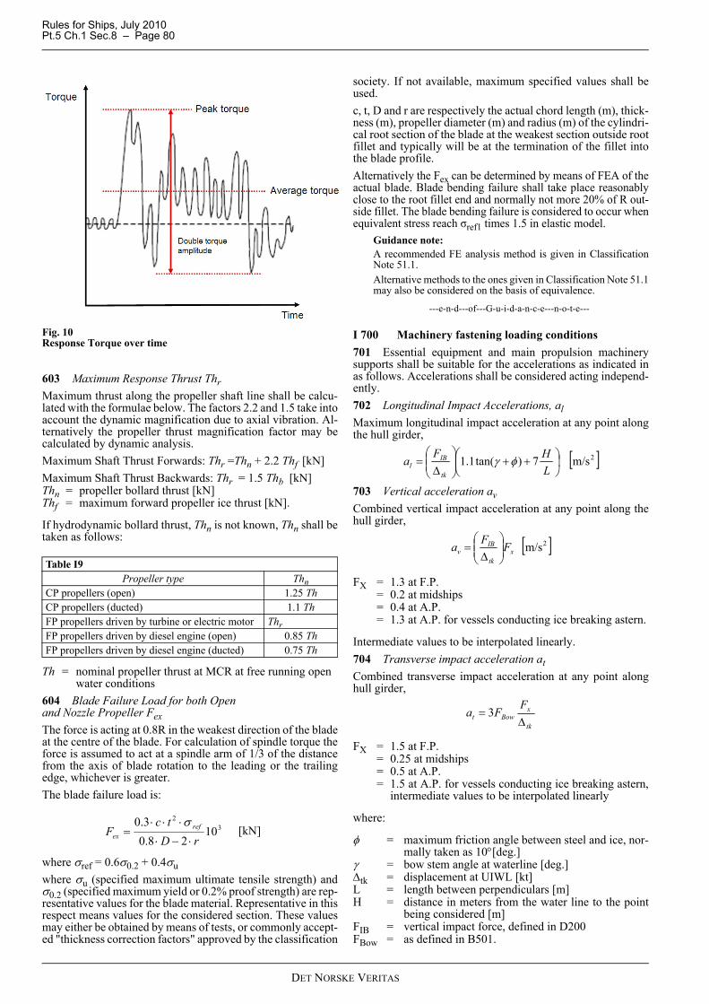
Rules for Ships, July 2010Pt.5 Ch.1 Sec.8 – Page 80
Fig. 10Response Torque over time
603 Maximum Response Thrust ThrMaximum thrust along the propeller shaft line shall be calcu-lated with the formulae below. The factors 2.2 and 1.5 take intoaccount the dynamic magnification due to axial vibration. Al-ternatively the propeller thrust magnification factor may becalculated by dynamic analysis. Maximum Shaft Thrust Forwards: Thr =Thn + 2.2 Thf [kN]Maximum Shaft Thrust Backwards: Thr = 1.5 Thb [kN]Thn = propeller bollard thrust [kN]Thf = maximum forward propeller ice thrust [kN].
If hydrodynamic bollard thrust, Thn is not known, Thn shall betaken as follows:
Th = nominal propeller thrust at MCR at free running open water conditions
604 Blade Failure Load for both Open and Nozzle Propeller FexThe force is acting at 0.8R in the weakest direction of the bladeat the centre of the blade. For calculation of spindle torque theforce is assumed to act at a spindle arm of 1/3 of the distancefrom the axis of blade rotation to the leading or the trailingedge, whichever is greater.The blade failure load is:
where σref = 0.6σ0.2 + 0.4σuwhere σu (specified maximum ultimate tensile strength) andσ0.2 (specified maximum yield or 0.2% proof strength) are rep-resentative values for the blade material. Representative in thisrespect means values for the considered section. These valuesmay either be obtained by means of tests, or commonly accept-ed "thickness correction factors" approved by the classification
society. If not available, maximum specified values shall beused.c, t, D and r are respectively the actual chord length (m), thick-ness (m), propeller diameter (m) and radius (m) of the cylindri-cal root section of the blade at the weakest section outside rootfillet and typically will be at the termination of the fillet intothe blade profile. Alternatively the Fex can be determined by means of FEA of theactual blade. Blade bending failure shall take place reasonablyclose to the root fillet end and normally not more 20% of R out-side fillet. The blade bending failure is considered to occur whenequivalent stress reach σref1 times 1.5 in elastic model.
Guidance note:A recommended FE analysis method is given in ClassificationNote 51.1. Alternative methods to the ones given in Classification Note 51.1may also be considered on the basis of equivalence.
---e-n-d---of---G-u-i-d-a-n-c-e---n-o-t-e---
I 700 Machinery fastening loading conditions701 Essential equipment and main propulsion machinerysupports shall be suitable for the accelerations as indicated inas follows. Accelerations shall be considered acting independ-ently.702 Longitudinal Impact Accelerations, alMaximum longitudinal impact acceleration at any point alongthe hull girder,
703 Vertical acceleration avCombined vertical impact acceleration at any point along thehull girder,
FX = 1.3 at F.P.= 0.2 at midships= 0.4 at A.P.= 1.3 at A.P. for vessels conducting ice breaking astern.
Intermediate values to be interpolated linearly.704 Transverse impact acceleration atCombined transverse impact acceleration at any point alonghull girder,
FX = 1.5 at F.P.= 0.25 at midships= 0.5 at A.P.= 1.5 at A.P. for vessels conducting ice breaking astern,
intermediate values to be interpolated linearly
where:
φ = maximum friction angle between steel and ice, nor-mally taken as 10°[deg.]
γ = bow stem angle at waterline [deg.]Δtk = displacement at UIWL [kt]L = length between perpendiculars [m] H = distance in meters from the water line to the point
being considered [m]FIB = vertical impact force, defined in D200FBow = as defined in B501.
Table I9Propeller type Thn
CP propellers (open) 1.25 ThCP propellers (ducted) 1.1 ThFP propellers driven by turbine or electric motor ThrFP propellers driven by diesel engine (open) 0.85 ThFP propellers driven by diesel engine (ducted) 0.75 Th
32
1028.0
3.0rD
tcF ref
ex ⋅−⋅
⋅⋅⋅=
σ[kN]
[ ]2m/s7)tan(1.1 ⎟⎠⎞
⎜⎝⎛ ++⎟⎟
⎠
⎞⎜⎜⎝
⎛Δ
=LHFa
tk
IBl φγ
[ ]2m/sxtk
IBv FFa ⎟⎟
⎠
⎞⎜⎜⎝
⎛Δ
=
tk
xBowt
FFa
Δ= 3
DET NORSKE VERITAS
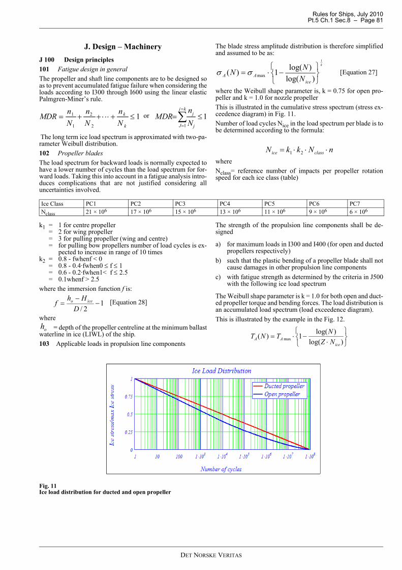
Rules for Ships, July 2010 Pt.5 Ch.1 Sec.8 – Page 81
J. Design – MachineryJ 100 Design principles101 Fatigue design in generalThe propeller and shaft line components are to be designed soas to prevent accumulated fatigue failure when considering theloads according to I300 through I600 using the linear elasticPalmgren-Miner’s rule.
The long term ice load spectrum is approximated with two-pa-rameter Weibull distribution.102 Propeller bladesThe load spectrum for backward loads is normally expected tohave a lower number of cycles than the load spectrum for for-ward loads. Taking this into account in a fatigue analysis intro-duces complications that are not justified considering alluncertainties involved.
The blade stress amplitude distribution is therefore simplifiedand assumed to be as:
where the Weibull shape parameter is, k = 0.75 for open pro-peller and k = 1.0 for nozzle propellerThis is illustrated in the cumulative stress spectrum (stress ex-ceedence diagram) in Fig. 11.Number of load cycles Nice in the load spectrum per blade is tobe determined according to the formula:
whereNclass= reference number of impacts per propeller rotationspeed for each ice class (table)
k1 = 1 for centre propeller = 2 for wing propeller = 3 for pulling propeller (wing and centre) = for pulling bow propellers number of load cycles is ex-
pected to increase in range of 10 timesk2 = 0.8 - fwhenf < 0 = 0.8 - 0.4·fwhen0 ≤ f ≤ 1 = 0.6 - 0.2·fwhen1< f ≤ 2.5 = 0.1whenf > 2.5 where the immersion function f is:
where = depth of the propeller centreline at the minimum ballast
waterline in ice (LIWL) of the ship.103 Applicable loads in propulsion line components
The strength of the propulsion line components shall be de-signed
a) for maximum loads in I300 and I400 (for open and ductedpropellers respectively)
b) such that the plastic bending of a propeller blade shall notcause damages in other propulsion line components
c) with fatigue strength as determined by the criteria in J500with the following ice load spectrum
The Weibull shape parameter is k = 1.0 for both open and duct-ed propeller torque and bending forces. The load distribution isan accumulated load spectrum (load exceedence diagram). This is illustrated by the example in the Fig. 12.
Fig. 11Ice load distribution for ducted and open propeller
12
2
1
1 ≤+⋅⋅⋅++=k
k
Nn
Nn
NnMDR
1
1
≤=∑=
=
kj
J j
j
Nn
MDRor
k
iceAA N
NN1
)log()log(1)( max
⎭⎬⎫
⎩⎨⎧
−⋅= σσ [Equation 27]
nNkkN classice ⋅⋅⋅= 21
Ice Class PC1 PC2 PC3 PC4 PC5 PC6 PC7Nclass 21 × 106 17 × 106 15 × 106 13 × 106 11 × 106 9 × 10⁶ 6 × 10⁶
12/
−−
=D
Hhf iceo [Equation 28]
oh
⎭⎬⎫
⎩⎨⎧
⋅−⋅=
)log()log(1)( maxice
AA NZNTNT
DET NORSKE VERITAS
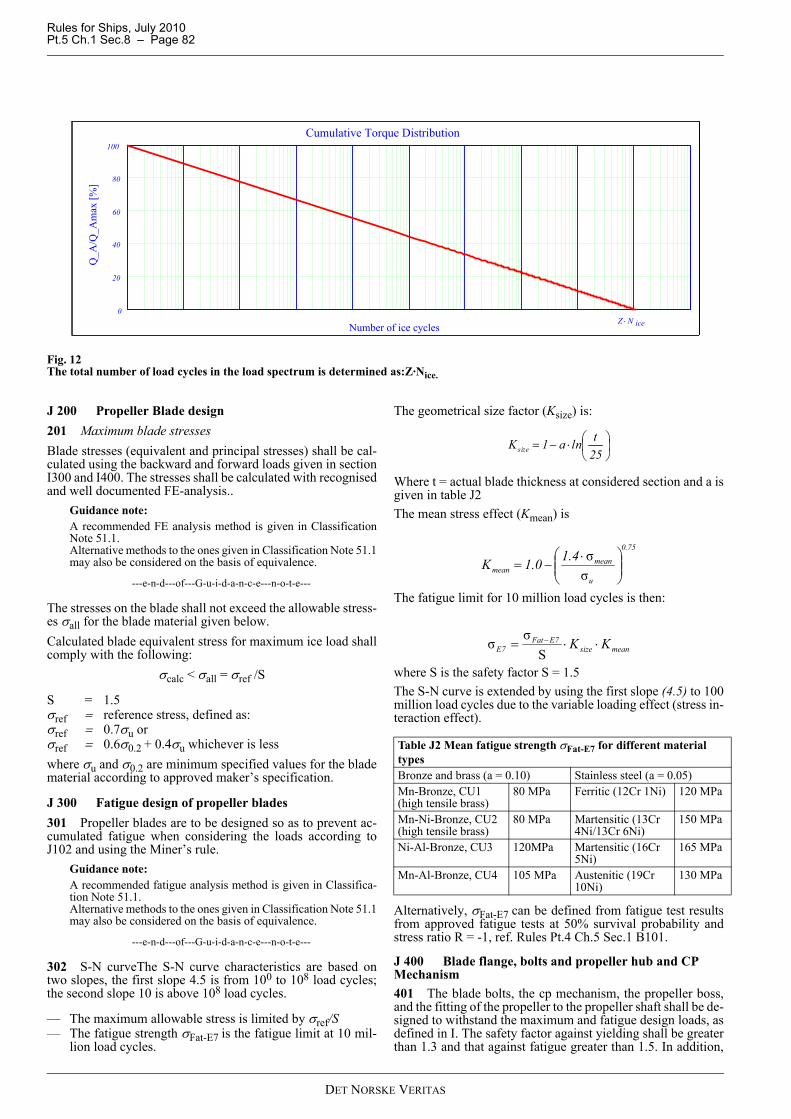
Rules for Ships, July 2010Pt.5 Ch.1 Sec.8 – Page 82
Fig. 12The total number of load cycles in the load spectrum is determined as:Z·Nice.
J 200 Propeller Blade design 201 Maximum blade stressesBlade stresses (equivalent and principal stresses) shall be cal-culated using the backward and forward loads given in sectionI300 and I400. The stresses shall be calculated with recognisedand well documented FE-analysis..
Guidance note:A recommended FE analysis method is given in ClassificationNote 51.1. Alternative methods to the ones given in Classification Note 51.1may also be considered on the basis of equivalence.
---e-n-d---of---G-u-i-d-a-n-c-e---n-o-t-e---
The stresses on the blade shall not exceed the allowable stress-es σall for the blade material given below.Calculated blade equivalent stress for maximum ice load shallcomply with the following:
σcalc < σall = σref /S
S = 1.5σref = reference stress, defined as:σref = 0.7σu or σref = 0.6σ0.2 + 0.4σu whichever is less where σu and σ0.2 are minimum specified values for the bladematerial according to approved maker’s specification.
J 300 Fatigue design of propeller blades301 Propeller blades are to be designed so as to prevent ac-cumulated fatigue when considering the loads according toJ102 and using the Miner’s rule.
Guidance note:A recommended fatigue analysis method is given in Classifica-tion Note 51.1. Alternative methods to the ones given in Classification Note 51.1may also be considered on the basis of equivalence.
---e-n-d---of---G-u-i-d-a-n-c-e---n-o-t-e---
302 S-N curveThe S-N curve characteristics are based ontwo slopes, the first slope 4.5 is from 100 to 108 load cycles;the second slope 10 is above 108 load cycles.
— The maximum allowable stress is limited by σref/S— The fatigue strength σFat-E7 is the fatigue limit at 10 mil-
lion load cycles.
The geometrical size factor (Ksize) is:
Where t = actual blade thickness at considered section and a isgiven in table J2The mean stress effect (Kmean) is
The fatigue limit for 10 million load cycles is then:
where S is the safety factor S = 1.5The S-N curve is extended by using the first slope (4.5) to 100million load cycles due to the variable loading effect (stress in-teraction effect).
Alternatively, σFat-E7 can be defined from fatigue test resultsfrom approved fatigue tests at 50% survival probability andstress ratio R = -1, ref. Rules Pt.4 Ch.5 Sec.1 B101.
J 400 Blade flange, bolts and propeller hub and CP Mechanism401 The blade bolts, the cp mechanism, the propeller boss,and the fitting of the propeller to the propeller shaft shall be de-signed to withstand the maximum and fatigue design loads, asdefined in I. The safety factor against yielding shall be greaterthan 1.3 and that against fatigue greater than 1.5. In addition,
0
20
40
60
80
100Cumulative Torque Distribution
Number of ice cycles
Q_A
/Q_A
max
[%]
Z N ice⋅
Table J2 Mean fatigue strength σFat-E7 for different material typesBronze and brass (a = 0.10) Stainless steel (a = 0.05)Mn-Bronze, CU1 (high tensile brass)
80 MPa Ferritic (12Cr 1Ni) 120 MPa
Mn-Ni-Bronze, CU2 (high tensile brass)
80 MPa Martensitic (13Cr 4Ni/13Cr 6Ni)
150 MPa
Ni-Al-Bronze, CU3 120MPa Martensitic (16Cr 5Ni)
165 MPa
Mn-Al-Bronze, CU4 105 MPa Austenitic (19Cr 10Ni)
130 MPa
⎟⎠⎞
⎜⎝⎛⋅−=
25tlna1Ksize
75.0
u
meanmean
4.10.1K ⎟⎟⎠
⎞⎜⎜⎝
⎛ ⋅−=
σσ
meansize7EFat
7E KK ⋅⋅= −
Sσσ
DET NORSKE VERITAS
Rules for Ships, July 2010 Pt.5 Ch.1 Sec.8 – Page 83
the safety factor for loads resulting from loss of the propellerblade through plastic bending as defined in I604 shall be great-er than 1 against yielding.
Guidance note:A recommended fatigue analysis method is given in Classifica-tion Note 51.1. Alternative methods to the ones given in Classification Note 51.1may also be considered on the basis of equivalence.
---e-n-d---of---G-u-i-d-a-n-c-e---n-o-t-e---
402 Blade bolts shall withstand following bending momentconsidered around bolt pitch circle, or an other relevant axisfor not circular joints, parallel to considered root section witha safety factor of 1.0:
where rbolt= radius to the bolt plan [m]403 Blade bolt pre-tension shall be sufficient to avoid sepa-ration between mating surfaces with maximum forward andbackward ice loads in I301 - I302 and I401 - I402 (open andducted respectively).404 Separate means, e.g. dowel pins, have to be provided inorder to withstand a spindle torque resulting from blade failure(I604) Qsex or ice interaction Qsmax (I303), whichever is great-er. A safety factor S of 1.0 is required. The minimum diameterof the pins is:
PCD = Pitch circle diameter [mm]i = number of pinsQs = max(Qsmax; Qsex ) - Qfr1 - Qfr2 [kNm] σ0.2 = yield strength of dovel pin material
Qfr1 = friction torque in blade bearings caused by thereaction forces due to Fex
Qfr2 = friction between connected surfaces resultingfrom blade bolt pretension forces.
Lex = maximum of distance from spindle axis to theleading, or trailing edge at radius 0,8R
Coefficient of friction = 0.15 may normally be applied in calculation of
Qfr1,2.405 Components of CP mechanisms are to be designed towithstand the blade failure spindle torque Qsex and maximumice spindle torque.The blade failure spindle torque Qsex shall not lead to any con-sequential damages. Fatigue strength is to be considered for parts transmitting thespindle torque from blades to a servo system considering icespindle torque acting on one blade. The maximum amplitudeis defined as:
Provided that calculated stresses duly considering local stressconcentrations are less than yield strength, or maximum 70%of σu of respective materials, detailed fatigue analysis is not re-quired. In opposite case components shall be analysed for cu-mulative fatigue. 406 Design pressure for servo system shall be taken as apressure caused by Qsmax or Qsex when not protected by relief
valves, reduced by relevant friction losses in bearings causedby the respective ice loads. Design pressure shall in any casebe less than relief valve set pressure
J 500 Propulsion Line Components501 Propeller fitting to the shaftA. Keyless cone mountingThe friction capacity (at 0o C) shall be at least 2.0 times thehighest peak torque Tpeak [kNm] as determined in I600 withoutexceeding the permissible hub stresses.The necessary surface pressure can be determined as:
where
μ = 0.14 for steel-steel, = 0.13 for steel-bronze DS = is the shrinkage diameter at mid-length of taper [m]L = is the effective length of taper [m]Above friction coefficients may be increased by 0.04 if glycer-ine is used in wet mountingB. Key mountingKey mounting is not permitted.C. Flange mounting
I The flange thickness is to be at least 25% of the shaft di-ameter.
II Any additional stress raisers such as recesses for boltheads shall not interfere with the flange fillet unless theflange thickness is increased correspondingly.
III The flange fillet radius is to be at least 10% of the shaft di-ameter.
IV The diameter of ream fitted (light press fit) bolts shall bechosen so that the peak torque does not cause shear stress-es beyond 30% of the yield strength of the bolts.
V The bolts are to be designed so that the blade failure loadFex (I604) does not cause yielding.
502 Propeller shaftThe propeller shaft is to be designed to fulfil the following:A. The blade failure load Fex (I604) applied parallel to the shaft(forward or backwards) shall not cause yielding. Bending mo-ment need not to be combined with any other loads.The diameter dp in way of the aft stern tube bearing shall notbe less than:
where
σy = minimum specified yield or 0.2% proof strength ofthe propeller shaft material [MPa]
dp = propeller shaft diameter [mm]di = propeller shaft inner diameter [mm]σ0.2 = propeller material yield stress [MPa].Forward from the aft stern tube bearing the diameter may bereduced based on direct calculation of actual bending mo-ments, or by the assumption that the bending moment causedby Fex is linearly reduced to 50% at the next bearing and infront of this linearly to zero at third bearing.Bending due to maximum blade forces Fb and Ff have beendisregarded since the resulting stress levels are much below thestresses due to the blade failure load.
)2
8.0( boltexbolt rDFM −= [kNm]
2.0
3 3810σπ ⋅⋅⋅
⋅⋅=
iPCDQd s [mm]
exexsex LFQ31
= [kNm]
2maxsfsb
sa
QQQ
+= [kNm]
320 100.22
⋅⋅⋅⋅
⋅⋅=° LD
Tp
S
peakC μπ
[MPa]
34
4
2.0 1σ160
⎟⎟⎠
⎞⎜⎜⎝
⎛−⋅
⋅⋅=
dd
DFd
i
exp [mm]
DET NORSKE VERITAS
Rules for Ships, July 2010Pt.5 Ch.1 Sec.8 – Page 84
B. The stresses due to the peak torque Tpeak [kNm] shall havea minimum safety factor of 1.5 against yielding in plain sec-tions and 1.0 in way of stress concentrations in order to avoidbent shafts. Minimum diameter of
where αt is the local stress concentration factor in torsion.Notched shaft diameter shall in any case not be less than the re-quired plain shaft diameter.C. The torque amplitudes with the foreseen number of cyclesshall be used in an accumulated fatigue evaluation with thesafety factors as defined below.
Guidance note:A recommended fatigue analysis method is given in Classifica-tion Note 51.1 with further references to the CN 41.4. Alternative methods to the ones given in Classification Note 51.1may also be considered on the basis of equivalence.
---e-n-d---of---G-u-i-d-a-n-c-e---n-o-t-e---
D. For plants with reversing direction of rotation the stressrange Δτ·αt resulting from forward Tpeakf to astern Tpeakb shallnot exceed twice the yield strength (in order to avoid stress-strain hysteresis loop) with a safety factor of 1.5, i.e.:
The fatigue strengths σF and τF (3 million cycles) of shaft ma-terials may be assessed on the basis of the material’s yield or0.2% proof strength as:
This is valid for small polished specimens (no notch) and re-versed stresses, see “VDEH 1983 Bericht Nr. ABF11 Berech-nung von Wöhlerlinien für Bauteile aus Stahl”. The high cycle fatigue (HCF) is to be assessed based on theabove fatigue strengths, notch factors (i.e. geometrical stressconcentration factors and notch sensitivity), size factors, meanstress influence and the required safety factor of 1.5.The low cycle fatigue (LCF) representing 103 cycles is tobased on the lower value of either half of the stress range cri-terion (see D) ) or the smaller value of yield or 0.7 of tensilestrength/√3. Both criteria utilise a safety factor of 1.5.The LCF and HCF as given above represent the upper and low-er knees in a stress-cycle diagram. Since the required safetyfactors are included in these values, a Miner sum of unity is ac-ceptable.503 Intermediate shaftsThe intermediate shafts are to be designed to fulfil the follow-ing:A. The stresses due to the peak torque Tpeak [kNm] shall havea minimum safety factor of 1.5 against yielding in plain sec-tions and 1.0 in way of stress concentrations in order to avoidbent shafts.
Minimum diameter of
where αt is the local stress concentration factor in torsion.Notched shaft diameter shall in any case not be less than the re-quired plain shaft diameter.B. The torque amplitudes with the foreseen number of cyclesshall be used in an accumulated fatigue evaluation with thesafety factors as defined below.
Guidance note:A recommended fatigue analysis method is given in Classifica-tion Note 51.1. Alternative methods to the ones given in Classification Note 51.1may also be considered on the basis of equivalence.
---e-n-d---of---G-u-i-d-a-n-c-e---n-o-t-e---
C. For plants with reversing direction of rotation the stressrange Δτ·αt [MPa] resulting from forward Tpeakf to asternTpeakb shall not exceed twice the yield strength (in order toavoid hysteresis) with a safety factor of 1.5, i.e.:
The fatigue strengths σF and τF (3 million cycles) of shaft ma-terials may be assessed on the basis of the material’s yield or0.2% proof strength as:
This is valid for small polished specimens (no notch) and re-versed stresses, see “VDEH 1983 Bericht Nr. ABF11 Berech-nung von Wöhlerlinien für Bauteile aus Stahl”. The high cycle fatigue (HCF) is to be assessed based on theabove fatigue strengths, notch factors (i.e. geometrical stressconcentration factors and notch sensitivity), size factors, meanstress influence and the required safety factor of 1.5.The low cycle fatigue (LCF) representing 103 cycles is tobased on the lower value of either half of the stress range cri-terion (see C) or the smaller value of yield or 0.7 of tensilestrength/√3. Both criteria utilise a safety factor of 1.5.The LCF and HCF as given above represent the upper and lowerknees in a stress-cycle diagram. Since the required safety factorsare included in these values, a Miner sum of unity is acceptable.504 Shaft connectionsA. Shrink fit couplings (keyless)The friction capacity shall be at least 1.8 times the highest peaktorque Tpeak as determined in I602 without exceeding the per-missible hub stresses.The necessary surface pressure can be determined as:
where
μ = coefficient of friction = 0.14 for steel to steel with oilinjection (= 0.18 if glycerine injection)
DS = is the shrinkage diameter at mid-length of taper [m]L = is the effective length of taper [m].
plain shaft:
notched shat:
34
4
2.0 1σ237
⎟⎟⎠
⎞⎜⎜⎝
⎛−⋅
⋅=
dd
Td
i
peak
3
4
4
2.0 1σ
α207
⎟⎟⎠
⎞⎜⎜⎝
⎛−
⋅⋅=
dd
Td
i
tpeak
5.13
2
⋅
⋅≤⋅Δ y
t
σατ [MPa]
377436.0 2.0 ⋅=+⋅= FF τσσ [MPa]
plain shaft:
notched shat:
34
4
2.0 1σ237
⎟⎟⎠
⎞⎜⎜⎝
⎛−⋅
⋅=
dd
Td
i
peak
3
4
4
2.0 1σ
α207
⎟⎟⎠
⎞⎜⎜⎝
⎛−
⋅⋅=
dd
Td
i
tpeak
5.13
2
⋅
⋅≤⋅Δ y
t
σατ [MPa]
377436.0 2.0 ⋅=+⋅= FF τσσ [MPa]
32 108.12
⋅⋅⋅⋅
⋅⋅=
LDT
pS
peak
μπ[MPa]
[mm]
[mm]
DET NORSKE VERITAS

Rules for Ships, July 2010 Pt.5 Ch.1 Sec.8 – Page 85
B. Key mountingKey mounting is not permitted.C. Flange mounting
I The flange thickness is to be at least 20% of the shaft di-ameter.
II Any additional stress raisers such as recesses for boltheads shall not interfere with the flange fillet unless theflange thickness is increased correspondingly.
III The flange fillet radius is to be at least 8% of the shaft di-ameter.
IV The diameter of ream fitted (light press fit) bolts or pinsshall be chosen so that the peak torque does not causeshear stresses beyond 30% of the yield strength of thebolts or pins.
V The bolts are to be designed so that the blade failure load(I604) in backwards direction does not cause yielding.
505 Gear transmissionsA. ShaftsShafts in gear transmissions shall meet the same safety level asintermediate shafts, but where relevant, bending stresses andtorsional stresses shall be combined (e.g. by von Mises).
Guidance note:A recommended fatigue analysis method is given in Classifica-tion Note 51.1. Alternative methods to the ones given in Classification Note 51.1may also be considered on the basis of equivalence.
---e-n-d---of---G-u-i-d-a-n-c-e---n-o-t-e---
Maximum permissible deflection in order to maintain suffi-cient tooth contact pattern is to be considered for the relevantparts of the gear shafts. B. GearingThe gearing shall fulfil following 3 acceptance criteria:
1) tooth root fracture2) pitting of flanks3) scuffing.
In addition to above 3 criteria subsurface fatigue may need tobe considered.Common for all criteria is the influence of load distributionover the face width. All relevant parameters are to be consid-ered, such as elastic deflections (of mesh, shafts and gear bod-ies), accuracy tolerances, helix modifications, and workingpositions in bearings (especially for twin input single outputgears).The load spectrum (see J103) may be applied in such a waythat the numbers of load cycles for the output wheel are multi-plied by a factor of (number of pinions on the wheel / number
of propeller blades Z). For pinions and wheels with higherspeed the numbers of load cycles are found by multiplicationwith the gear ratios. The peak torque (Tpeak) is also to be con-sidered.
Guidance note:The acceptance criteria for calculation assessment are given be-low. They refer to calculation methods as given in ClassificationNote 41.2, comprising information on calculation of tooth rootstrength (root fractures), flank surface durability (pitting,spalling, case crushing and tooth fractures starting from theflank), scuffing and subsurface fatigue.Alternative methods to the ones given in Classification Note 41.2may also be considered on the basis of equivalence.
---e-n-d---of---G-u-i-d-a-n-c-e---n-o-t-e---
Tooth root safety shall be assessed against the peak torque,torque amplitudes (with the pertinent average torque) as wellas the ordinary loads (free water running) by means of accumu-lated fatigue analyses. The resulting safety factor is to be atleast 1.5. The safety against pitting shall be assessed in the same way astooth root stresses, but with a minimum resulting safety factorof 1.2. The scuffing safety (flash temperature method – ref. Classifica-tion Note 41.2) based on the peak torque shall be at least 1.2 whenthe FZG class of the oil is assumed one stage below specification. The safety against subsurface fatigue of flanks for surfacehardened gears (oblique fracture from active flank to oppositeroot) shall be assessed at the discretion of each society. BearingsSee section I509.506 ClutchesClutches shall have a static friction torque of at least 1.3 timesthe peak torque and dynamic friction torque 2/3 of the static.Emergency operation of clutch after failure of e.g. operatingpressure shall be made possible within reasonably short time.If this is arranged by bolts, it shall be on the engine side of theclutch in order to ensure access to all bolts by turning the en-gine.507 Elastic couplingsThere shall be a separation margin of at least 20% between thepeak torque and the torque where any twist limitation isreached.The torque amplitude (or range Δ) shall not lead to fatigue crack-ing, i.e. exceeding the permissible vibratory torque. The permis-sible torque may be determined by interpolation in a log-logtorque-cycle diagram where TKmax1 respectively ΔTKmax referto 50,000 cycles and TKV refer to 106 cycles. See illustration inFig. 13, 14 and 15.
DET NORSKE VERITAS

Rules for Ships, July 2010Pt.5 Ch.1 Sec.8 – Page 86
508 CrankshaftsSpecial considerations apply for plants with large inertia (e.g. fly-wheel, tuning wheel or PTO) in the non-driving end of the engine.509 BearingsAll shaft bearings are to be designed to withstand the propellerblade ice interaction loads according to I300 and I400. For thepurpose of calculation the shafts are assumed to rotate at ratedspeed. Reaction forces due to the response torque (e.g. in geartransmissions) are to be considered.Additionally the aft stern tube bearing as well as the next shaft-line bearing are to withstand Fex as given in I600, in such a waythat the ship can maintain operational capability.Rolling bearings are to have a L10a lifetime of at least 40 000hours according to ISO-281. Thrust bearings and their housings are to be designed to with-stand maximum response thrust I600 and the force resultingfrom the blade failure force Fex. For the purpose of calculationexcept for Fex the shafts are assumed to rotate at rated speed.For pulling propellers special consideration is to be given toloads from ice interaction on propeller hub. 510 SealsBasic requirements for seals:A. Seals are to prevent egress of pollutants, and be suitable forthe operating temperatures. Contingency plans for preventingthe egress of pollutants under failure conditions are to be doc-umented.B. Seal are to be of type approved type or otherwise of provendesign.
J 600 Azimuthing Main Propulsion601 In addition to the above requirements, special consider-ation shall be given to those loading cases which are extraordi-nary for propulsion units when compared with conventionalpropellers. The estimation of loading cases has to reflect theway of operation of the ship and the thrusters. In this respect,for example, the loads caused by the impacts of ice blocks onthe propeller hub of a pulling propeller have to be considered.Furthermore, loads resulting from the thrusters operating at anoblique angle to the flow have to be considered. The steeringmechanism, the fitting of the unit, and the body of the thrustershall be designed to withstand the loss of a blade without dam-age. The loss of a blade shall be considered for the propellerblade orientation which causes the maximum load on the com-ponent being studied. Typically, top-down blade orientationplaces the maximum bending loads on the thruster body.602 Azimuth thrusters shall also be designed for estimatedloads due to thruster body/ice interaction as per sub-section E.The thruster body has to stand the loads obtained when themaximum ice blocks, which are given in I201, strike the thrust-er body when the ship is at a typical ice operating speed. In ad-dition, the design situation in which an ice sheet glides alongthe ship’s hull and presses against the thruster body should beconsidered. The thickness of the sheet should be taken as thethickness of the maximum ice block entering the propeller, asdefined in I200.603 Design criteria for azimuth propulsorsAzimuth propulsors shall be designed for following loads:
1) Ice pressure on strut based on defined location area of thestrut / ice interaction as per subsection E.
Fig. 13 Fig. 14
Fig. 15
DET NORSKE VERITAS

Rules for Ships, July 2010 Pt.5 Ch.1 Sec.8 – Page 87
2) Ice pressure on pod based on defined location area ofthruster body / ice interaction as per subsection E.
3) Plastic bending of one propeller blade in the worst position(typically top-down) without consequential damages toany other part
4) Steering gear design torque TSG shall be minimum 60% ofsteering torque expected at propeller ice milling conditiondefined as Tmax
TSG = 0.6(Tmax / 0.8R) l [kNm]where l is distance from the propeller plane to steering (az-imuth) axis [m].
5) Steering gear shall be protected by effective means limit-ing excessive torque caused by:
a) Ice milling torque exceeding design torque and lead-ing to rotation of unit
b) Torque caused by plastic bending of one propellerblade in the worse position (related to steering gear)and leading to rotation of the unit.
6) Steering gear shall be ready for operation after above load,5)a) or 5)b) has gone.
J 700 Steering system701 Rudder stops are to be provided. The design ice force onrudder shall be transmitted to the rudder stops without damageto the steering system.702 Ice knife shall in general be fitted to protect the rudderin centre position. The ice knife shall extend below BWL. De-sign forces shall be determined according to the subsection E.703 The effective holding torque of the rudder actuator, atsafety valve set pressure, is obtained by multiplying the openwater requirement at design speed (maximum 18 knots) by fol-lowing factors:
The holding torque shall be limited to the actual twisting ca-pacity of the rudder stock calculated at its yield strength (ref.Pt.4 Ch.14) 704 The rudder actuator shall be protected by torque reliefarrangements, assuming the following turning speeds [deg/s]without undue pressure rise (ref. Pt.4 Ch.14 for undue pressurerise):
705 Additional fast acting torque relief arrangements (actingat 15% higher pressure than set pressure of safety valves in 704shall provide effective protection of the rudder actuator in caseof the rudder is pushed rapidly hard over against the stops as-suming following turning speeds [deg/s].
The arrangement shall be so that steering capacity can bespeedily regained.
J 800 Prime movers801 Engines shall be capable of being started and running thepropeller in bollard condition.802 Propulsion plants with CP propeller shall be capable be-ing operated even in case with the CP system in full pitch aslimited by mechanical stoppers.803 Provisions shall be made for heating arrangements to
ensure ready starting of the cold emergency power units at anambient temperature applicable to the Polar class of the ship.804 Emergency power units shall be equipped with startingdevices with a stored energy capability of at least three consec-utive starts at the design temperature in I100 above The sourceof stored energy shall be protected to preclude critical deple-tion by the automatic starting system, unless a second inde-pendent means of starting is provided. A second source ofenergy shall be provided for an additional three starts within 30min., unless manual starting can be demonstrated to be effec-tive.
J 900 Auxiliary systems901 Machinery shall be protected from the harmful effects ofingestion or accumulation of ice or snow. Where continuousoperation is necessary, means should be provided to purge thesystem of accumulated ice or snow.902 Means should be provided to prevent damage due tofreezing, to tanks containing liquids.903 Vent pipes, intake and discharge pipes and associatedsystems shall be designed to prevent blockage due to freezingor ice and snow accumulation.
J 1000 Sea inlets, cooling water systems and ballast tanks1001 Cooling water systems for machinery that are essentialfor the propulsion and safety of the vessel, including sea chestsinlets, shall be designed for the environmental conditions ap-plicable to the ice class.1002 At least two sea chests shall be arranged as ice boxesfor class PC-1 to PC-5 inclusive where. The calculated vol-ume for each of the ice boxes shall be at least 1 m3 for every750 kW of the total installed power. For PC-6 and PC-7 thereshall be at least one ice box located preferably near centre line.1003 Ice boxes shall be designed for an effective separationof ice and venting of air.1004 Sea inlet valves shall be secured directly to the ice box-es. The valve shall be a full bore type. 1005 Ice boxes and sea bays shall have vent pipes and shallhave shut off valves connected direct to the shell.1006 Means shall be provided to prevent freezing of seabays, ice boxes, ship side valves and fittings above the loadwater line.1007 Efficient means shall be provided to re-circulate cool-ing seawater to the ice box. Total sectional area of the circulat-ing pipes shall not be less than the area of the cooling waterdischarge pipe.1008 Detachable gratings or manholes shall be provided forice boxes. Manholes shall be located above the deepest loadline. Access shall be provided to the ice box from above.1009 Openings in ship sides for ice boxes shall be fitted withgratings, or holes or slots in shell plates. The net area throughthese openings shall be not less than 5 times the area of the in-let pipe. The diameter of holes and width of slot in shell platingshall be not less than 20 mm. Gratings of the ice boxes shall beprovided with a means of clearing. Clearing pipes shall be pro-vided with screw-down type non return valves.
J 1100 Ballast tanks1101 Efficient means shall be provided to prevent freezing infore and after peak tanks and wing tanks located above the wa-ter line and where otherwise found necessary.
J 1200 Ventilation systems1201 The air intakes for machinery and accommodation ven-tilation shall be located on both sides of the ship.1202 Accommodation and ventilation air intakes shall be
Ice Class PC1 PC2 PC3 PC4 PC5 PC6 PC7Factor 5 5 3 3 3 2 1,5
Ice Class PC1–2 PC3-5 PC6 - 7Turning speeds [deg/s] 8 6 4
Ice Class PC1–2 PC3-5 PC6 - 7Turning speeds [deg/s] 40 20 10
DET NORSKE VERITAS
Rules for Ships, July 2010Pt.5 Ch.1 Sec.8 – Page 88
provided with means of heating.1203 The temperature of inlet air provided to machineryfrom the air intakes shall be suitable for the safe operation ofthe machinery
J 1300 Alternative design1301 As an alternative, a comprehensive design study maybe submitted and may be requested to be validated by anagreed test programme.
K. Stability and Watertight IntegrityK 100 General101 The stability requirements according to Sec.4 L applyexcept as stated in 102.102 For ships of Polar Classes 5, 6 and 7 not carrying anypolluting or hazardous cargoes, damage may be assumed to beconfined between watertight bulkheads, except where suchbulkheads are spaced at less than the damage dimension.
DET NORSKE VERITAS
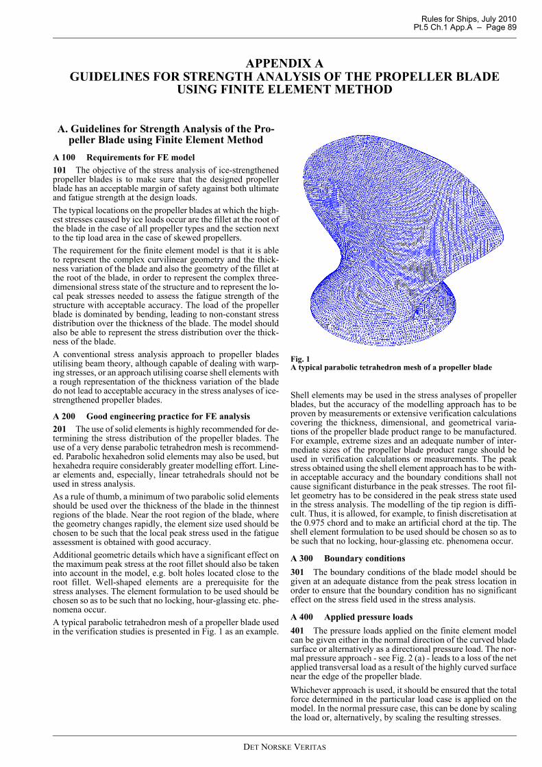
Rules for Ships, July 2010 Pt.5 Ch.1 App.A – Page 89
APPENDIX A GUIDELINES FOR STRENGTH ANALYSIS OF THE PROPELLER BLADE
USING FINITE ELEMENT METHOD
A. Guidelines for Strength Analysis of the Pro-peller Blade using Finite Element Method
A 100 Requirements for FE model101 The objective of the stress analysis of ice-strengthenedpropeller blades is to make sure that the designed propellerblade has an acceptable margin of safety against both ultimateand fatigue strength at the design loads. The typical locations on the propeller blades at which the high-est stresses caused by ice loads occur are the fillet at the root ofthe blade in the case of all propeller types and the section nextto the tip load area in the case of skewed propellers.The requirement for the finite element model is that it is ableto represent the complex curvilinear geometry and the thick-ness variation of the blade and also the geometry of the fillet atthe root of the blade, in order to represent the complex three-dimensional stress state of the structure and to represent the lo-cal peak stresses needed to assess the fatigue strength of thestructure with acceptable accuracy. The load of the propellerblade is dominated by bending, leading to non-constant stressdistribution over the thickness of the blade. The model shouldalso be able to represent the stress distribution over the thick-ness of the blade.A conventional stress analysis approach to propeller bladesutilising beam theory, although capable of dealing with warp-ing stresses, or an approach utilising coarse shell elements witha rough representation of the thickness variation of the bladedo not lead to acceptable accuracy in the stress analyses of ice-strengthened propeller blades.
A 200 Good engineering practice for FE analysis 201 The use of solid elements is highly recommended for de-termining the stress distribution of the propeller blades. Theuse of a very dense parabolic tetrahedron mesh is recommend-ed. Parabolic hexahedron solid elements may also be used, buthexahedra require considerably greater modelling effort. Line-ar elements and, especially, linear tetrahedrals should not beused in stress analysis. As a rule of thumb, a minimum of two parabolic solid elementsshould be used over the thickness of the blade in the thinnestregions of the blade. Near the root region of the blade, wherethe geometry changes rapidly, the element size used should bechosen to be such that the local peak stress used in the fatigueassessment is obtained with good accuracy. Additional geometric details which have a significant effect onthe maximum peak stress at the root fillet should also be takeninto account in the model, e.g. bolt holes located close to theroot fillet. Well-shaped elements are a prerequisite for thestress analyses. The element formulation to be used should bechosen so as to be such that no locking, hour-glassing etc. phe-nomena occur.A typical parabolic tetrahedron mesh of a propeller blade usedin the verification studies is presented in Fig. 1 as an example.
Fig. 1A typical parabolic tetrahedron mesh of a propeller blade
Shell elements may be used in the stress analyses of propellerblades, but the accuracy of the modelling approach has to beproven by measurements or extensive verification calculationscovering the thickness, dimensional, and geometrical varia-tions of the propeller blade product range to be manufactured.For example, extreme sizes and an adequate number of inter-mediate sizes of the propeller blade product range should beused in verification calculations or measurements. The peakstress obtained using the shell element approach has to be with-in acceptable accuracy and the boundary conditions shall notcause significant disturbance in the peak stresses. The root fil-let geometry has to be considered in the peak stress state usedin the stress analysis. The modelling of the tip region is diffi-cult. Thus, it is allowed, for example, to finish discretisation atthe 0.975 chord and to make an artificial chord at the tip. Theshell element formulation to be used should be chosen so as tobe such that no locking, hour-glassing etc. phenomena occur.
A 300 Boundary conditions301 The boundary conditions of the blade model should begiven at an adequate distance from the peak stress location inorder to ensure that the boundary condition has no significanteffect on the stress field used in the stress analysis.
A 400 Applied pressure loads401 The pressure loads applied on the finite element modelcan be given either in the normal direction of the curved bladesurface or alternatively as a directional pressure load. The nor-mal pressure approach - see Fig. 2 (a) - leads to a loss of the netapplied transversal load as a result of the highly curved surfacenear the edge of the propeller blade. Whichever approach is used, it should be ensured that the totalforce determined in the particular load case is applied on themodel. In the normal pressure case, this can be done by scalingthe load or, alternatively, by scaling the resulting stresses.
DET NORSKE VERITAS

Rules for Ships, July 2010Pt.5 Ch.1 App.A – Page 90
The directional pressure is better suited to propeller bladestress analyses. The pressure can be given on a surface in a di-rection defined using, for example, a local coordinate system;see Fig. 2 (b).
Fig. 2aOne possible way to apply the pressure load to the propel-ler blade. If the pressure load is given in the normal direc-tion of the highly curved blade (Fig.a) surface, the resultingnet applied load will be less than the intended load andshould be scaled appropriately.
Fig. 2bSecond alternative: If the pressure load is given in a fixeddirection (Fig.b), the net applied load is directly the intend-ed load.
DET NORSKE VERITAS