SGT-LP Series PDH Microwave Radio Technical...
32
SGT-LP Series PDH Microwave Radio Technical Overview
Transcript of SGT-LP Series PDH Microwave Radio Technical...

SGT-LP Series
PDH
Microwave
Radio
Technical
Overview
1
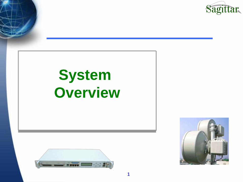
System
Overview

3
Transmission Capacity:
4 x 2.048 Mb/s (4E1),
8 x 2.048 Mb/s (8E1),
16 x 2.048 Mb/s (16E1),
1 x 34 Mb/s (E3),
Fast Ethernet+1/2/4E1 (14MHz or 28MHz)
Operating Mode:
1+0
1+1 Hot standby system
Service Channels:
2 auxiliary data channels:
A phone channel: engineering order wire
Network management channel: RS232, 10Base-T
SGT-LP System Description
4
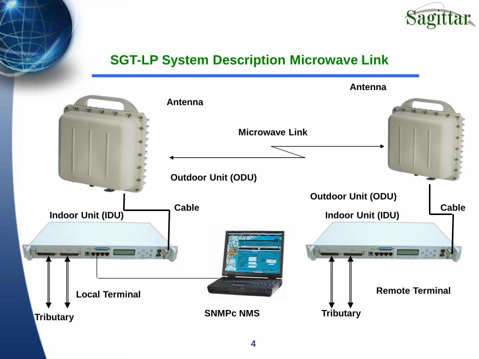
Local Terminal Remote Terminal
SNMPc NMS
Indoor Unit (IDU)
Outdoor Unit (ODU)
Antenna
Cable Indoor Unit (IDU)
Cable
Antenna
Outdoor Unit (ODU)
Tributary Tributary
Microwave Link
SGT-LP System Description Microwave Link

5
High performance and integrated design incorporating high & new technology
Easy-to-install
Single coaxial cable connection between Indoor and Outdoor Units
Adjustable transmit output power
Frequency/channel setting via LCD panel or NMS
Diagnostic loopbacks accessible via LCD panel or NMS
253 different Device ID codes (same as last number of IP address)
One Base Unit supports all different service cards, such as E3 card, 4E1 card, 8E1 card, 16E1 card, 2/4E1+FE card
Software scalable capacity
Auxiliary Alarm input and Relays output
Features

6
Digital Modulator and Demodulator, Forward-Error-Correction (FEC)
High sensitivity and High System Gain
Low power consumption, using 3.3V and 1.5V working voltages
Standard radio IF frequencies on the cable: 310MHz/70MHz
No cable length settings or adjustments required, RG-8/U cable up to 300m
Protection Switch Option available
SNMP (NMI) Option available
WEB Server supported for network management
Features

8
SGT-LP IDU

9
IDU Features
1 Rack Unit (RU) high, 19” wide
4 external alarm input sensors as standard
5 alarm relay outputs as standard
Control and diagnostics features through front panel keypad:
· Transmission Capacity select
· Frequency of operation
· Transmitter Power adjustment
· Device ID · Tributary status
· Transmitter On/Off · ATPC
· Beep and Light Alarm
· RSSI
· Current BER
· Alarm summary status
· Transmitter Power Status
· Auto Locate Alarm and display

10
IDU Features
The same Base Unit supports all of the following service cards
TRIBS-B TRIBS-A
4/8/16E1(75ohm unbalanced)
LINK LTXRX
RATE WTXRX
10/100BASE-T
TRIBS
IN OUT A 1
B 1
2 3
3 4
4
2
C 1
D 1
2 3
3 4
4
LINK LTXRX
RATE WTXRX
10/100BASE-T
TRIBS
1 2 3 4
FE+1/2/4E1 (75ohm unbalanced)
1E3 (75ohm unbalanced) 4/8/16E1 (120ohm balanced)
10/100BASE-T+1/2/4E1 (120ohm balanced)

11
IDU Overview
DC IN
V.11
V.24
Alarm
Relays
Phone
Service
Card
Switch
TO ODU Keypad
LED
Indicators
LCD
Grounding
10BASE-T
RS232

12
4/8/16E1 Service Card
TRIBS-B TRIBS-A
Capacity Configuration: 4E1, 8E1, 16E1
According to 7MHz, 14MHz, 28MHz Bandwidth
A 1
B 1
2 3
3 4
4
2
C 1
D 1
2 3
3 4
4

13
4/8/16E1 Service Card
Digital Interface: ITU-T Rec. G.703
Connectors:
RJ-48 Connector for 120 Ohm balanced
DB37 Connector for 75 Ohm unbalanced
For DB37 CC4 Coaxial Connector Adaptor supported
Digital Code: HDB3

14
FE+1/2/4E1 Service Card
LINK LTXRX
RATE WTXRX
10/100BASE-T
TRIBS
LINK LTXRX
RATE WTXRX
10/100BASE-T
TRIBS
1 2 3 4
Capacity Configuration: 14MHz, 28MHz
Service Configuration: 1E1,2E1,4E1

15
FE+1/2/4E1 Service Card
Capacity: 34Mbps @28MHz bandwidth 17Mbps @14MHz
bandwidth
Digital Interface E1: ITU-T Rec. G.703
Digital Interface 10/100BASE-T: IEEE 802.3
Connectors:
10/100BASE-T: RJ45 100 Ohm unbalanced
E1:RJ-48 Connector for 120 Ohm balanced
E1:DB37 Connector for 75 Ohm unbalanced
For DB37 CC4 Coaxial Connector Adaptor supported
Digital Code: E1:HDB3

16
1E3 Service Card
IN OUT
Capacity Configuration: 1E3
According to 28MHz Bandwidth
Digital Interface :ITU-T Rec. G.703
Connectors: BNC for 75 Ohm unbalanced
Digital Code: HDB3

17
PCB IN IDU
IDU Main Board Service Card
IDU
LCD&Key
Board

18
Licensed PDH
Outdoor Unit
(ODU)
19
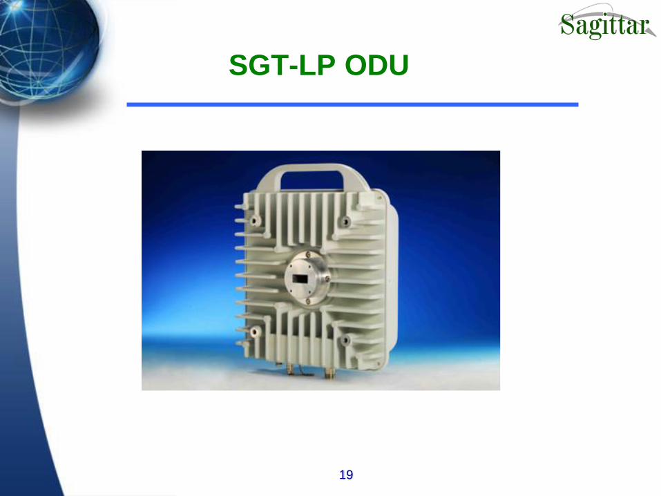
SGT-LP ODU

20
ODU Frequency Range
• ODU covers all of the standard frequency bands
specified in ITU-R
• ITU-R frequency bands are achieved using
Sub-bands in the ODU’s
• The standard frequency bands are 1. 5 GHz band
4.4-5.0GHz As per ITU-R F.1093-3
2. Lower 6 GHz band
5.9-6.4GHz As per ITU-R F.383-6
3. Upper 6 GHz band
6.4-7.1 GHz As per ITU-R F.384-7
4. 7 GHz band
7.1-8.2GHz As per ITU-R F.385-6

21
ODU Frequency Range
5. 8 GHz band
8.2-8.5GHz As per ITU-R F.386-6
6. 13 GHz band
12.7-13.3GHz As per ITU-R F.497-6
7. 15 GHz band
14.4-15.4GHz As per ITU-R F.636-3
All the frequency bands are covered using standard TR spacings

22
ODU Specification
General Specification
Frequency Source / Stability Synthesizer ± 5 ppm
RF Channel Selection IDU controlled via NMS
Modulation Type QPSK
Receiver Type Dual conversion
Intermediate Frequency 310MHz / 70MHz
Transmitter
Output Power Up to +25dBm
Attenuation Control Range 20dB
Receiver
Noise Figure < 4.0 dB
Overload -20 dBm
Receiver Sensitivity (1E-6 BER) -87dBm/4E1, -84dBm/8E1, -81dBm/16E1
System Gain Up to 112dB
Dimension / Weight 300 x 260 x 56 mm^3 / 6Kg
Temperature / Humidity -33 ~ +55C, / 0% ~ 100%
Power Supply / consumption -40 VAC to -60 VAC / 39W

23
Power Output
PDH
– 5/6/7 GHz: 26 dBm
– 8/11 GHz: 24 dBm
– 13/15 GHz: 23 dBm

24
Interfaces
IF Cable
– N(F) Cable interface
Received Signal Strength Indicator (RSSI)
– Analog test point indicating voltage (0-5V) proportional to received power in dBm
– Uncalibrated but monotonic: a weaker signal will always result in a lower voltage, and vice-versa. High voltage (4.5V-5V) approx. corresponds to -25dBm
Low voltage (0.5V-1V) approx corresponds -80dBm or lower
– Connector: BNC female

25
Antenna Interface
Low frequencies (11GHz and lower)
– Coaxial interface (any antenna may be used)
– Connector: N-type jack
High frequencies (13GHz and above)
– Either Waveguide (any antenna may be used)
Direct mount (antenna needs to mechanically integrate with ODU)
– Connector: proprietary flange
(flange adaptor available from supplier)
26
SGT-LP
Network Management System

27
NMS-Structure
HUB

28
NMS-SNMPc

30
Protection System
-Hot Standby
-Frequency Diversity
-2+0
-Space Diversity
31
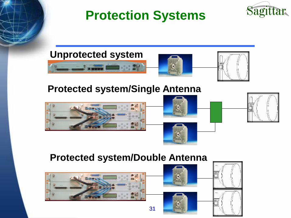
Protection Systems
Unprotected system
Protected system/Single Antenna
Protected system/Double Antenna

32
Protection Switch
V11 Connect
to IDU-A
Connect to
IDU-B
Connect to
IDU-A
Phone
Connect to
IDU-A
Phone
Connect to
IDU-B
V24 Connect
to IDU-A
V11 Connect
to IDU-A
V24 Connect
to IDU-A
33
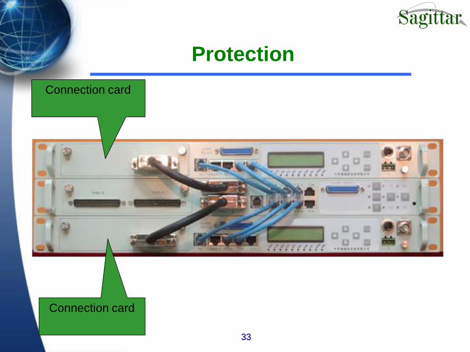
Protection
Connection card
Connection card
34
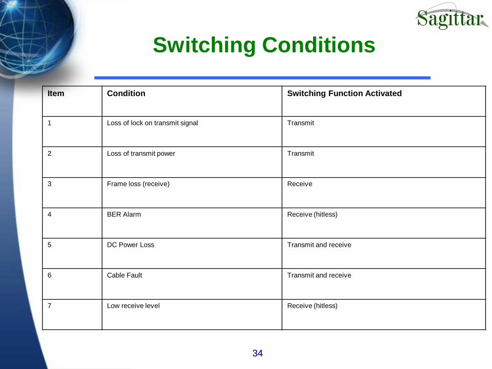
Switching Conditions
Item Condition Switching Function Activated
1 Loss of lock on transmit signal Transmit
2 Loss of transmit power Transmit
3 Frame loss (receive) Receive
4 BER Alarm Receive (hitless)
5 DC Power Loss Transmit and receive
6 Cable Fault Transmit and receive
7 Low receive level Receive (hitless)