IDU User Manual
69
IDU IDU Integrated Data Unit User Manual 资料版本 1.1 归档时间 2007-08-03 BOM 编码 31011389 Version 1.1 Revision date August 03, 2007 BOM 31011389 艾默生网络能源有限公司为客户提供全方位的 技术支持,用户可与就近的艾默生网络能源有 限公司办事处或客户服务中心联系,也可直接 与公司总部联系。 艾默生网络能源有限公司 版权所有,保留一切权利。内容如有改动,恕 不另行通知。 艾默生网络能源有限公司 地址:深圳市南山区科技工业园科发路一号 邮编:518057 公司网址: www.emersonnetworkpower.com.cn 客户服务投诉热线:0755-86010800 E-mail:[email protected] Emerson Network Power provides customers with technical support. Users may contact the nearest Emerson local sales office or service center. Copyright © 2007 by Emerson Network Power Co., Ltd. All rights reserved. The contents in this document are subject to change without notice. Emerson Network Power Co., Ltd. Address: No.1 Kefa Rd., Science & Industry Park, Nanshan District 518057, Shenzhen China Homepage: www.emersonnetworkpower.com.cn E-mail: [email protected]
-
Upload
hungfetbkhn -
Category
Documents
-
view
241 -
download
0
Transcript of IDU User Manual

8/6/2019 IDU User Manual
http://slidepdf.com/reader/full/idu-user-manual 1/68
IDU
IDU Integrated Data Unit
User Manual
资料版本 1.1
归档时间 2007-08-03
BOM编码 31011389
Version 1.1
Revision date August 03, 2007
BOM 31011389
艾默生网络能源有限公司为客户提供全方位的
技术支持,用户可与就近的艾默生网络能源有
限公司办事处或客户服务中心联系,也可直接
与公司总部联系。
艾默生网络能源有限公司
版权所有,保留一切权利。内容如有改动,恕
不另行通知。
艾默生网络能源有限公司
地址:深圳市南山区科技工业园科发路一号
邮编:518057
公司网址:
www.emersonnetworkpower.com.cn
客户服务投诉热线:0755-86010800
E-mail:[email protected]
Emerson Network Power provides customers with
technical support. Users may contact the nearest
Emerson local sales office or service center.
Copyright © 2007 by Emerson Network Power
Co., Ltd.
All rights reserved. The contents in this document
are subject to change without notice.
Emerson Network Power Co., Ltd.
Address: No.1 Kefa Rd., Science & Industry Park,
Nanshan District 518057, Shenzhen China
Homepage: www.emersonnetworkpower.com.cn
E-mail: [email protected]

8/6/2019 IDU User Manual
http://slidepdf.com/reader/full/idu-user-manual 2/68
Content
Chapter 1 Overview .......................................................... ........................................................................... ....................... 1
1.1 Features............................................ ............................................................ ........................................................ 1
1.2 Appearance .................................................. ....................................................... ................................................. 1
1.3 Parts .................................................... ....................................................... .......................................................... 2
1.3.1 Parts Overview ................................................... ............................................................................ ........... 2
1.3.2 IDU .................................................... ........................................................ ................................................ 2
1.3.3 IDU-BAT................................................ ....................................................... ............................................. 4
1.3.4 IDU-BRG .......................................................... ............................................................................. ............ 5
1.3.5 IDU-COM4............................................ ........................................................ ............................................. 6
Chapter 2 Installing IDU ........................................................ ....................................................................... ....................... 7
2.1 Getting Started............................ ........................................................... ............................................................... 7
2.1.1 Precautions............................................................ ........................................................................ ............ 7
2.1.2 Environmental Requirement ........................................................ .............................................................. 7
2.1.3 Heat Sink Requirement............................................................................. ................................................. 7
2.1.4 Unpacking............................................................... ....................................................................... ............ 7
2.1.5 Installation Tools.............................. ........................................................... ............................................... 8
2.2 Assembling IDU ........................................................ ...................................................................... ...................... 8
2.3 Installing IDU ................................................... ........................................................ ............................................. 8
2.3.1 Installing IDU In Cabinet....................................................... ................................................................... .. 9
2.3.2 Installing IDU On A Wall ....................................................... ................................................................... 10
2.3.3 Installing IDU On A Workbench.............................................................. ................................................. 10
2.4 Installing Sensors (Optional)......................................................... ...................................................................... 11
2.4.1 Installing Smoke Sensor........................................................ .................................................................. 11
2.4.2 Installing Water Sensor........................................................................ .................................................... 12
2.4.3 Installing Infrared Sensor...................... ........................................................ ........................................... 12
2.4.4 Installing Door Status Sensor ........................................................ .......................................................... 13
2.4.5 Installing THS .................................................. ........................................................ ................................ 13
Chapter 3 System Wiring ................................................ ....................................................... ........................................... 15
3.1 Preparation ..................................................... ....................................................................... ............................. 15
3.2 IDU Wiring ....................................................... ...................................................................... ............................. 15
3.2.1 IDU-AI Wiring......................................... ............................................................ ...................................... 15
3.2.2 Battery Total Voltage Ports Wiring................................................................................. .......................... 18
3.2.3 Connecting Smoke Sensor.................................................... .................................................................. 19
3.2.4 Connecting Water Sensor................................................................ ........................................................ 20
3.2.5 Connecting Door Status Sensor ............................................................ .................................................. 21
3.2.6 Connecting Infrared Sensor................. ................................................................ .................................... 22
3.2.7 Serial Ports Wiring..................................................... ......................................................................... ..... 23

8/6/2019 IDU User Manual
http://slidepdf.com/reader/full/idu-user-manual 3/68
3.2.8 Connecting THS ...................................................... ........................................................................... ..... 25
3.2.9 Relay Ports Wiring..................................................... ......................................................................... ..... 26
3.3 Restoring Boards ........................................................ ........................................................................ ................ 26
3.4 Wiring Of IDU-BAT......................................................................... ..................................................................... 26
3.4.1 Ports Positions........................................................ ............................................................................ ..... 26
3.4.2 Wiring For Measuring Battery Voltage.......................................................... ........................................... 27
3.4.3 Wiring For Measuring Battery Current .............................................................. ....................................... 27
3.4.4 Jumper Configuration ............................................... ........................................................................... .... 28
3.5 Wiring Of IDU-BRG........................................... ........................................................ .......................................... 28
3.5.1 Ports Positions........................................................ ............................................................................ ..... 28
3.5.2 Wiring ......................................................... ............................................................................. ................ 28
3.5.3 Hardware Configuration......................... ........................................................... ....................................... 29
3.6 Wiring of IDU-COM4........... ........................................................... ..................................................................... 31 3.7 Connecting Grounding Cables....................................................... ..................................................................... 33
3.8 Connecting DC Cable .......................................................... .......................................................................... ..... 33
3.9 Installing Baffle Plane ................................................................ ......................................................................... 34
Chapter 4 Commissioning IDU.......... ........................................................ ........................................................................ 35
4.1 Connecting IDU To A Computer ............................................................. ............................................................ 35
4.1.1 Connecting IDU To Computer Through Network Port ................................................... .......................... 35
4.1.2 Connecting IDU To Computer Through CONSOLE Port .......................................................... ............... 36
4.2 Starting IDU .................................................... ....................................................................... ............................. 38
4.2.1 Preparation.................................................... .......................................................................... ................ 38 4.2.2 Procedure..................................................... ........................................................ ................................... 39
4.3 Logging Into IDU.................................................. ............................................................................ ................... 39
4.4 Configuring Parameters....................................................... .......................................................................... ..... 39
4.4.1 Data Conversion.................. ........................................................ ............................................................ 39
4.4.2 Configuring Analog Input Channels ........................................................ ................................................. 39
4.4.3 Configuring Battery total Voltage Input Channels......... ....................................................................... .... 41
4.4.4 Configuring Sensor Input Channels........................................................ ................................................. 42
4.4.5 Configuring Relay Output Channel ........................................................ .................................................. 43
4.4.6 Configuring Serial Ports....................... ........................................................... ......................................... 45
4.4.7 Configuring IDU-BAT Channels.................................................................... ........................................... 46
4.5 Commissioning IDU With Tools99 ....................................................... ............................................................... 48
4.5.1 Overview.................................................................................. ................................................................ 48
4.5.2 Installing And Starting Tools99 ................................................................ ................................................ 48
4.5.3 Preparation.................................................... .......................................................................... ................ 48
4.5.4 Testing IDU-IO.......................................................... .......................................................................... ..... 49
4.5.5 Tesing Control Function.......................................................... ................................................................. 50
4.5.6 Testing IDU-BAT ....................................................... ......................................................................... ..... 50
4.5.7 Testing Serial Ports .................................................. .......................................................................... ..... 51
4.5.8 Testing IDU..................................................... ........................................................ ................................. 51

8/6/2019 IDU User Manual
http://slidepdf.com/reader/full/idu-user-manual 4/68
4.5.9 Quitting Tools99 ....................................................... .......................................................................... ..... 51
4.6 Upgrading Iolan Application ........................................................... ..................................................................... 52
Chapter 5 Common Troubleshooting ........................................................ ........................................................................ 54
Chapter 6 Technical Specification.......... ........................................................... ................................................................ 55
6.1 Specification Of IDU.......................................................... .............................................................................. .... 55
6.1.1 Input Parameters...................................................... .......................................................................... ..... 55
6.1.2 Output Parameters ................................................... ............................................................................ ... 56
6.2 Specification Of IDU-BRG1/IDU-BRG2............................................................. .................................................. 56
6.2.1 Communication Ports ............................................... ........................................................................... .... 56
6.3 Specification Of IDU-BAT1/IDU-BAT2 ............................................................... ................................................. 56
6.3.1 Performance........................................................ ............................................................................... ..... 56
6.3.2 Ports Specification............... ....................................................... ............................................................. 56
6.4 Specification Of IDU-COM4....................................................... ......................................................................... 57
6.4.1 Communication Ports ............................................... ........................................................................... .... 57
6.5 Sensors.......................................................... ........................................................................ ............................. 57
6.6 Environmental Requirement ............................................................ ................................................................... 58
6.7 Transport Requirement...................................................... ............................................................................ ..... 58
6.8 Mechanical Specification ..................................................... .......................................................................... ..... 59
Appendix 1 Command Line Interface .......................................................... ...................................................................... 60
1. Overview............................. ............................................................ ...................................................................... 60
2. Starting Command Line ......................................................... .......................................................................... ..... 60
3. Commonly Used Commands........................................................... ..................................................................... 60

8/6/2019 IDU User Manual
http://slidepdf.com/reader/full/idu-user-manual 5/68
Chapter 1 Overview 1
IDU Integrated Data Unit User Manual
Chapter 1 Overview
This chapter presents an overview of IDU integrated data unit (for short, IDU), including its features, appearance,
parts, ports, and indicators.
1.1 Features
IDU is an intelligent data collecting system integrated providing all the data collection functions necessary to industry
control & monitor system. IDU can be used in E1 or TCP/IP networks and can be flexibly configured according to
different application requirements.
IDU provides:
z Collection of signals from temperature and humidity, smoke, water, door status, and anti-theft sensors
z Ten AI inputs, supportive of 4 ~ 20mA current signal or 0 ~ 10V voltage signal
z Measurement of 2 batteries’ voltage, batteries’ total voltage is less than 60Vdc
z Four relay normally open(NO) contact outputs
z Four serial ports, configurable through jumpers
z Protection against power polarity reverse connection
This command outputs system hardware and software information.
1.2 Appearance
Figure 1-1 shows the appearance of IDU.
POWER indicator RUN indicator
Figure 1-1 IDU appearance
On the front panel of IDU, there are two indicators: POWER indicator and RUN indicator.
Table 1-1 Indicators on front panel
Silk print Function Status DescriptionOn Power is normal
POWER Indicates power Off Power fails
On IDU is starting upRUN Indicates running status
Flashing at 0.5Hz IDU operates normally

8/6/2019 IDU User Manual
http://slidepdf.com/reader/full/idu-user-manual 6/68
2 Chapter 1 Overview
IDU Integrated Data Unit User Manual
1.3 Parts
1.3.1 Parts Overview
IDU provides two compatible slots to accommodate such boards as IDU-BRG, IDU-BAT, and IDU-COM4.
Table 1-2 gives a brief introduction of these parts.
Table 1-2 IDU parts
Part Description
IDU11Z -
IDU-BAT
Optional
There are two types of IDU-BAT:
IDU-BAT1: monitors one group of batteries
IDU-BAT2: monitors two groups of batteries
IDU-BRG
Optional
There are two types of IDU-BRG:
IDU-BRG1: provides two Ethernet ports and one E1 port
IDU-BRG2: provides two Ethernet ports and two E1 ports
IDU-COM4Optional
Provides four serial ports
Warning
None of the boards supports hot swapping.
1.3.2 IDU
Functions
IDU provides:
z Two expansion slots (either can accommodate an IDU board)
z One USB port
z One Ethernet port
z Ten analog input (AI) ports
z Battery total voltage channels
z Four relay outputs
z Sensor input ports (for input of temperature and humidity sensor (THS), infrared sensor, door status sensor,
smoke sensor, and water sensor)
z Four serial ports
Appearance
Figure 1-2 shows the IDU.

8/6/2019 IDU User Manual
http://slidepdf.com/reader/full/idu-user-manual 7/68
Chapter 1 Overview 3
IDU Integrated Data Unit User Manual
PE
Power switchPower input Ethernet port
CONSOLE port
Analog input
Battery voltage input
Slot2
Relay input
THS input
Smoke sensor input
Water sensor input Door status sensor input
Infrared sensor input
Slot1
USB
COM1COM4
COM3COM2
Figure 1-2 IDU (back panel)
Indicators
Nine indicators are provided on the back panel of IDU.
Table 1-3 IDU indicators
Silk print Definition Color Function Status Remark
On IDU is powered onPOWER Power indicator Green
Indicates the status of
power Off IDU is not powered on
Off IDU is not powered on
On IDU is startingRUN
Indicator for running
statusGreen
Indicates the status of
IDU running status Flashing at
0.5HzIDU is running normally
COM1 Indicator for serial port 1 Green
COM2 Indicator for serial port 2 GreenFlashing
Data is being sent or received at
serial ports
COM3 Indicator for serial port 3 Green
COM 4 Indicator for serial port 4 Green
Indicates the status of
serial portsOff
No data is being sent or received at
serial ports
Off No board is in slot 1SLOT 1 Indicator for slot 1 Green
Indicates the status of
slot 1 On Board in slot 1 is normal
Off No board is in slot 2SLOT 2 Indicator for slot 2 Green
Indicates the status of
slot 2 On Board in slot 2 is normal
ALARM Alarm indicator Red Indicates alarms - -
Ports
lists the ports provided by the IDU.
Table 1-4 IDU ports
Silk print Definition Function
POWER Power input port
Reverse connection of power polarities will not cause damage; IDU will work
normally after the power is connected correctly.Input voltage: 20V dc ~ 60V dc
Eth0 Ethernet port
Number: 1
Connector type: RJ-45
10/100M self-adaptive
Cross, direct cable self-adaptive
Console Debugging port
Connector type: RJ-45
Interface standard: RS-232
Baud rate: 115200bps
USB USB portNumber: 1
Type: A
RELAY1-4 Relay output port 4 NO contacts
THS
Temperature and humidity
sensor port To connect with IDU-THS
CH0~CH10 Analog input channels 1-10 Receive analog voltage signals or analog current signals

8/6/2019 IDU User Manual
http://slidepdf.com/reader/full/idu-user-manual 8/68
4 Chapter 1 Overview
IDU Integrated Data Unit User Manual
Silk print Definition Function
BAT VOL1 ~
BAT VOL2Battery total voltage input Receive battery group total voltage
SMOKE Smoke sensor input Connect to smoke sensor
WATER Water sensor input Connect to water sensor
DOOR Door status sensor input Connect to door status sensor
INFRARED Infrared sensor input Connect to infrared sensor
COM1 Serial port 1
COM2 Serial port 2
COM3 Serial port 3
COM4 Serial port 4
See Table 3-3
for configuration
Baud rate is one of the following:
1200bps, 2400bps, 4800bps, 8000bps, 9600bps,
10416bps, 19200bps
Word length: 5 ~ 8 bit
Parity check mode: None, Odd, Even, Mark, or Space
Stopbits: bits 1 and 2
Use pluggable connectors
1.3.3 IDU-BAT
IDU-BAT is available in two models: IDU-BAT1 and IDU-BAT2. They can measure battery voltage or battery group
current.
Function
z IDU-BAT1 can measure 24 battery cells and one charge/discharge current.
z IDU-BAT2 can measure 48 battery cells and two charge/discharge currents.
z Measurement range automatically adjustable among 2V, 6V, and 12V.
z Automatic zero/base calibration.
Appearance
Figure 1-3 shows IDU-BAT2. IDU-BAT2 provides two sets of battery cell voltage ports and two sets of battery current
ports. (IDU-BAT1 provides one set of battery cell voltage ports and one set of battery current ports.)
Battery cellvoltage ports 1
Battery currentports 1
Battery cellvoltage ports 2
Battery currentports 2
Figure 1-3 IDU-BAT2
Table 1-5 IDU-BAT portsSilk print Meaning Function Remark
BATTERY I Battery cell voltage 1 Measure voltage of 24 battery cellsMeasure battery voltage only
Available on both IDU-BAT1 and IDU-BAT2
BATTERY II Battery cell voltage 2 Measure voltage of 24 battery cellsMeasure battery voltage only
Available only on IDU-BAT2
I1 Battery current 1Measure battery charge or discharge
current
Measure battery voltage or battery current
Available on both IDU-BAT1 and IDU-BAT2
I2 Battery current 2Measure battery charge or discharge
current
Measure battery voltage or battery current
Available only on IDU-BAT2
Specification
Measurement precision: better than +/–0.2%FS (+/–5mV for 2V Battery; +/-15mV for 6V Battery; +/-30mV for 12VBattery)
Collecting speed: less than 5s for each battery group

8/6/2019 IDU User Manual
http://slidepdf.com/reader/full/idu-user-manual 9/68
Chapter 1 Overview 5
IDU Integrated Data Unit User Manual
1.3.4 IDU-BRG
IDU-BRG is available in two models: IDU-BRG1 and IDU-BRG2.
Function
IDU-BRG converts Ethernet data packets to formats that can be transmitted over E1 links. IDU-BRG1 provides two
Ethernet ports and one E1 port. IDU-BRG2 provides two Ethernet ports and two E1 ports (contained in the same DB9
connector), and therefore can be used to form an E1 loop to send data in two directions.
Appearance
Ethernet
port 0
E1 port
indicators
E1 portsEthernet
port 1
DIP switches
Jumper terminals
Ethernet port indicators
Figure 1-4 IDU-BRG1
Indicators
Table 1-6 lists the indicators on the front panel of the IDU-BRG1
Indicator Silk print Function Color Status RemarkOn Network connection is normal
Off No network connection
Connection status and data
sending/receiving indicator
of Ethernet port 0
Yellow
Flashing at 10Hz Data is being sent or received
On Speed is 100Mbps
Ethernet port
indicator Eth0
Speed indicator of Ethernet
port 0Green
Off No network connection or speed is
10Mbps
On Network connection is normal
Off No network connection
Connection status and data
sending/receiving indicator
of Ethernet port 1
Yellow
Flashing at 10Hz Data is being sent or received
On Speed is 100Mbps
Ethernet port
indicator Eth1
Speed indicator of Ethernet
port 1Green
Off No network connection or speed is
10Mbps
OnSynchronization is not maintained
for the local E1 receiving channelsLOSASynchronization status
indicator of E1 port ARed
Off Synchronization is normal
OnCarriers are lost for the local E1
receiving channnelsLOFACarrier status indicator of
E1 port ARed
Off Carriers are normal
OnSynchronization is not maintained
for the local E1 receiving channelsLOSBSynchronization status
indicator of E1 port BRed
Off Synchronization is normal
OnCarriers are lost for the local E1
receiving channnels
E1 port
indicator
LOFBCarrier status indicator of
E1 port BRed
Off Carriers are normal

8/6/2019 IDU User Manual
http://slidepdf.com/reader/full/idu-user-manual 10/68
6 Chapter 1 Overview
IDU Integrated Data Unit User Manual
1.3.5 IDU-COM4
Function
IDU-COM4 provides four serial ports.
Appearance
COM indicatorsPower indicator
Jumpers J1~J16
COM 1~4
Figure 1-5 IDU-COM4
Indicators
Five indicators are available on the panel of IDU-COM4. See table 1-7 for details of the indicators.
Table 1-7 IDU-COM4 indicators
Indicator Sink print Function Color Status Remark
On Power is onPower
indicator POWER Power status Green
Off Power is out
COM1 Status of COM1
COM2 Status of COM2On
The corresponding serial port is sending or
receiving data
COM3 Status of COM3
Serial port
indicator
COM 4 Status of COM4
Green
Off No data is being sent or received by the
corresponding serial port

8/6/2019 IDU User Manual
http://slidepdf.com/reader/full/idu-user-manual 11/68
Chapter 2 Installing IDU 7
IDU Integrated Data Unit User Manual
Chapter 2 Installing IDU
This chapter first describes the preparation for installing IDU, such as operation notes, environment requirements,
and unpacking inspection, and then the installation of IDU and sensors.
2.1 Getting Started
2.1.1 Precautions
To ensure safety of the product and installation personnel, take the following precautions:
z Never put the IDU in watery places and always prevent liquid from entering the IDU.
zWear an ESD wrist-wrap when installing the IDU.
z Arrange the wires properly, and do not put any heavy objects on the wire or stamp the wires.
z Ground the IDU properly.
z Always cut off the power before performing any hardware operation.
2.1.2 Environmental Requirement
Operating Environment
IDU is for indoor use only. Maintaining proper temperature and humidity helps protect the wires and prolong the life of
the IDU. See 6.6 Environmental Requirement .
Anti-static Requirement
To minimize static effects, take the following measures:
z Ground the IDU and the floor properly.
z Keep air cleanness (avoid dust entering the room).z Maintain proper temperature and humidity in the room.
zWear antistatic clothing and an ESD wrist-wrap when operating the IDU; if antistatic clothing or ESD wrist-wraps
are unavailable, wash your hands instead, which helps discharge the static.
Anti-EMI Requirement
Take the following measures for anti-EMI purpose:
z Use dedicated grounding devices for the working ground of the IDU and place the devices as far as possible
from grounding devices of other electrical product.
z Keep far away from high-power radio transmitter, radar, or high-frequency large current electrical equipment
z Use electromagnetic shielding if necessary.
2.1.3 Heat Sink Requirement
z Keep the IDU as far as possible from heat sources.
z It is recommended to install the IDU into a 19’ standard cabinet, where at least 10mm spacing is required around
the IDU for heat sink.
z If no such cabinet is available, place the IDU on a clean horizontal platform.
zWhen the ambient temperature is too high, install an air conditioner in the room.
2.1.4 Unpacking
After confirming the environment meets the requirements, you can start the installation. Before the installation, youshould open the container to inspect the IDU parts and accessories. Table 2-1 lists the parts and accessories needed
for an ordinary IDU (Sensors are also optional, which are not listed in the following table).

8/6/2019 IDU User Manual
http://slidepdf.com/reader/full/idu-user-manual 12/68
8 Chapter 2 Installing IDU
IDU Integrated Data Unit User Manual
Table 2-1 IDU parts and accessories
Part Quantity Note
IDU 1 -
Baffle plane 1 -
2.1.5 Installation Tools
The following tools are needed for the installation:
z Sharp nose pliers
z Diagonal cutting nippers
z Impact drill
z Adjustable spanner screwdriver
z Multimeter
2.2 Assembling IDU
Note
The IDU-BAT, IDU-BRG, IDU-COM4, and sensors are optional, so you can skip their installation and wiring if you do not
choose them.
When you choose IDU-BAT, IDU-BRG, or IDU-COM4, you should install them into IDU. The IDU-BAT, IDU-BRG, and
IDU-COM4 share the same installation procedure.
This section introduces the procedure for installing IDU-BAT2.
1. Put on antistatic gloves or wrist-wrap, and shut down the power supply of the IDU (need not remove power cable)
2. As shown in Figure 2-1, insert the IDU-BAT2 into slot 1 or slot 2 until it securely fits in the slot, and fasten the
screws on the sides of the IDU-BAT2
Figure 2-1 Inserting BAT2
3. After the boards are installed, put on the cover of the IDU, and fasten the screws. Figure 2-2 shows the case when
IDU-BAT and IDU-BRG are installed.
Figure 2-2 A complete IDU
2.3 Installing IDU
IDU can be installed:
z In cabinet
z On wall
z On workbench

8/6/2019 IDU User Manual
http://slidepdf.com/reader/full/idu-user-manual 13/68
Chapter 2 Installing IDU 9
IDU Integrated Data Unit User Manual
2.3.1 Installing IDU In Cabinet
The IDU can be installed into a 19’ standard cabinet.
Follow these steps to install an IDU into a cabinet:
1. Confirm that the cabinet and IDU are ready and ensure that the cabinet is tidy for the installation.
2. Fasten the hangers to the sides of the IDU with bolts M3, as shown in Figure 2-3.
Figure 2-3 Fastening hangers
In Figure 2-4, the hangers are fastened.
Figure 2-4 IDU with hangers fastened
3. Gently put the IDU onto the two guide rails and push it into the cabinet, as shown in Figure 2-5
Figure 2-5 Inserting IDU into cabinet
4. Use screws to fasten the hangers of IDU to the cabinet.

8/6/2019 IDU User Manual
http://slidepdf.com/reader/full/idu-user-manual 14/68
10 Chapter 2 Installing IDU
IDU Integrated Data Unit User Manual
2.3.2 Installing IDU On A Wall
Follow these steps to install an IDU on a wall:
1. Check and ensure that the environment meets the requirements
2. Fasten the three fixing clips onto the IDU back panel, as shown in Figure 2-6
Figure 2-6 Fastening fixing clips
3. Use the impact drill (Ф6.0mm) to drill three holes in the wall (maximum error: 1.3mm) according to the following
figure.
308.5
220
10
Figure 2-7 Reference for drilling holes (unit: mm)
4. Insert plastic expansion bolts into the holes, and put the IDU in position
Figure 2-8 Installing IDU
2.3.3 Installing IDU On A Workbench
If the preceding two installation modes are not feasible, you can directly put the IDU on a clean workbench, ensuring
the following:
z The workbench must be well balanced and grounded properly.
z A 100mm clearance must be maintained around the IDU.
z Do not put any objects on the IDU.

8/6/2019 IDU User Manual
http://slidepdf.com/reader/full/idu-user-manual 15/68
Chapter 2 Installing IDU 11
IDU Integrated Data Unit User Manual
2.4 Installing Sensors (Optional)
This section describes the installation of sensors. For their operating principles, types, and technical parameters, see
6.5 Sensors.
2.4.1 Installing Smoke Sensor
Figure 2-9 shows the smoke sensor.
Figure 2-9 Smoke sensor
Environmental Requirements
z The smoke sensor is used for fire detection during preliminary fire brewing stage when plenty of smog
generated.
z The smoke sensor should not be installed where: the relative humidity often exceeds 95%RH; the air flow speed
exceeds 5m/s; plenty of dust, thick fog, or corrosive gas is present; smoke is resident; or alcohol, aether, or
ketone type organic substances are present.
Installation Requirements
z The smoke sensor should be installed in the center of the ceiling.
z 0.5m clearance should be maintained around the smoke sensor; the smoke sensor should be installed at least
1.5m away from the air vent of the air conditioner, and at least 0.5m away from the air vent of the ceiling.
Installation Procedure
Use a PVC connector to connect the cabling trough and IDU base.
It is recommended to install IDU base before installing the cabling trough.
65mm
Percussion drill ( 6×40)
6 expansion tube
ST4.2×32 self-tapping screw
Alarm indicator
GA39 cabling trough
PVC tip
Figure 2-10 Smoke sensor installation

8/6/2019 IDU User Manual
http://slidepdf.com/reader/full/idu-user-manual 16/68
12 Chapter 2 Installing IDU
IDU Integrated Data Unit User Manual
2.4.2 Installing Water Sensor
Figure 2-11 shows the water sensor and installation size.
3 8 . 5
1 4 . 4
Figure 2-11 Water sensor and installation size
Installation Requirement
The water sensor should be horizontally positioned at a low place or in front of the communication equipment, with its
bigger half part downward.
Installation ProcedureChoose a place according to the installation requirements and place the water sensor at it, as shown in Figure 2-12.
Supporting
plane
Figure 2-12 Water sensor installation
2.4.3 Installing Infrared Sensor
Figure 2-13 shows the infrared sensor.
Figure 2-13 Infrared sensor
Environmental Requirement
z Do not expose the infrared sensor to sunlight or other source of strong light.
z No curtains are present within the detectable range.
z Keep proper distance from air conditioners, central heating, or other heat sources.
Installation Requirement
z Do not touch the pyroelectric component during installation, and keep the Fresnel lens clean. Do not install the
infrared sensor on the wall behind the door.
z Place the infrared sensor on the position facing the potential illegal entry and avoid obstacles within the
detectable range.
z Ensure the infrared sensor can be seen in the detectable range.

8/6/2019 IDU User Manual
http://slidepdf.com/reader/full/idu-user-manual 17/68
Chapter 2 Installing IDU 13
IDU Integrated Data Unit User Manual
Installation Procedure
1. Remove the back panel of the sensor to reveal the two installation holes. Mark positions (for drilling holes) on the
wall based on the relative positions of the installation holes, and drill two holes in the wall with the impact drill (aiguille
Ф6.0mm)
2. Insert plastic expansion bolts (Ф6.0 × 26) into the holes
3. Fasten the back panel with tapping screws (Ф
2.0mm) onto the wall4. Install the body of the sensor onto the back panel
2.4.4 Installing Door Status Sensor
Figure 2-14 shows the door status sensor.
Figure 2-14 Door status sensor
Installation Requirement
When the door is closed, only a maximum of 5mm distance is allowed between the two pats of the door status sensor;
if the distance exceeds 5mm, find a proper position for the sensor to meet the requirement.
Installation Procedure
1. Mark the positions of installation holes on the door
2. Drill two holes in the wall with the impact drill (Ф6.0mm aiguille) (when the metal is less than 1.5mm thick, use
Ф2.5mm aiguille; and when the metal is more than 2mm thick, use Ф2.8mm aiguille)
3. Insert plastic expansion bolts (Ф6.0 x 26) into the holes
4. Fasten the sensor with tapping screws (Ф2.0mm)
2.4.5 Installing THS
Figure 2-15 shows the THS.
Figure 2-15 THS
Environmental requirements
z It is recommended to use THS where air conditioner is available.
z THS is not suitable where relative humidity is over 90%RH for a long time.
z Do not use THS where corrosive gases or other pollution gases fill the air.
z Do not use THS in a place of long-term humid and pollution, such as battery room, diesel engine room, and
basement.
z Do not use THS in environment where the ambient temperature is below -20ºC.

8/6/2019 IDU User Manual
http://slidepdf.com/reader/full/idu-user-manual 18/68
14 Chapter 2 Installing IDU
IDU Integrated Data Unit User Manual
Installation Requirement
zWall installation is recommended, and the installation height should be about 1.5m.
z The THS shall be installed in a place with good ventilation. Do not install the sensors where the air is not
ventilated, or near air conditioner or air intake of the room where the temperature changes fast (air flow speed
better within 0.1m/s ~ 1m/s).
zThe THS shall not be blown by cold or hot air blowers directly.
z The THS shall not be installed at the ends of cabling trough.
Installation Procedure
1. Remove the back panel of the THS to reveal the three installation holes. Based on the relative positions of the
installation holes, drill three hole in the wall with the impact drill (aiguille Ф6.0mm)
2. Insert the plastic expansion bolt (Ф6.0 x 26) into the holes
3. Fasten the back panel with tapping screws (Ф2.0mm) onto the wall
4. Install the body of the THS onto the back panel

8/6/2019 IDU User Manual
http://slidepdf.com/reader/full/idu-user-manual 19/68
Chapter 3 System Wiring 15
IDU Integrated Data Unit User Manual
Chapter 3 System Wiring
This chapter describes the wiring of IDU, and the installation of the baffle plane in the case that IDU is installed on a
wall.
3.1 Preparation
Hardware configuration of IDU is needed, so before starting the wiring, remove the coverand flashboard.
Figure 3-1 shows the positions of the cover, IDU-BAT, and IDU-BRG.
IDU-BRG IDU - BAT
IDU
Figure 3-1 Cover, IDU-BAT, and IDU-BRG
3.2 IDU Wiring
3.2.1 IDU-AI Wiring
Ten AI ports (CH1 ~ CH2) are provided. The ten ports accept 4 ~ 20mA current or 0 ~ 10Vdc voltage, and will be
connected to various sensors. By default, ports CH1 ~ CH6 accept current signals and ports CH7 ~ CH10 acceptvoltage signals. In practice, the properties of these ports can be set through jumper configuration. See Jumper
Configuration in this section for details. When set to accepting voltage input, an IDU-AI port also accepts digital
signals.
Ports Positions
AI input ports
Figure 3-2 Position of AI ports
Screen Print
+12/24V
CH6AGND
CH3+12/24VCH1
CH2AGND
CH5+12/24V
CH4 AGND AGND
+12/24VCH7
AGND CH8
+12/24VCH9
CH10
Figure 3-3 Screen print of IDU-AI ports

8/6/2019 IDU User Manual
http://slidepdf.com/reader/full/idu-user-manual 20/68
16 Chapter 3 System Wiring
IDU Integrated Data Unit User Manual
Jumper Configuration
Figure 3-4 shows jumper terminals for configuring IDU-AI ports.
IDU
Area A
Amplified
view of A
J11~ J15
J1 ~ J 10
J1 ~J15 pin numbering
1 2 3
Figure 3-4 IDU-AI jumper terminals
J1 ~ J10 are used to decide whether CH1 ~ CH10 receive voltage signals or current signals. See Table 3-1 for
configuration of CH1 ~ CH10.
Table 3-1 IDU-AI ports configuration
Port Jumper terminal Configuration Default configuration
CH1 J1
CH2 J2
CH3 J3
CH4 J4
CH5 J5
CH6 J6
Pins 1 and 2 shorted: receive current signals
Pins 2 and 3 shorted: receive voltage signalsPins 1 and 2 shorted
CH7 J7
CH8 J8
CH9 J9
CH10 J10
Pins 1 and 2 shorted: receive current signals
Pins 2 and 3 shorted: receive voltage signalsPins 2 and 3 shorted
J11 ~ J15 are used to decide the output (+12V or +24V) of VOUT1 ~ VOUT5
Table 3-2 IDU-Vout1-7 configuration
Port Jumper terminal Configuration Default configuration
Vout1 J11
Vout2 J12
Vout3 J13
Vout4 J14
Vout5 J15
Pins 1 and 2 shorted: +12V output
Pins 2 and 3 shorted: +24V outputPins 1 and 2 shorted
Wiring
Figure 3-5 shows the wiring of a sensor or transducer (2-wire) that outputs 4 ~ 20mA current and needs +24V power
supply.
SignalsSensor (or
transducer)
CH1
AGND
+12/24 V
CH2
Jumper configuration
To output +24V voltage
1 2 3
For sensor (or transducer) outputting current J1
J112 31
Figure 3-5 Wiring of a sensor (2-wire) that outputs 4 ~ 20mA and needs +24V power supply

8/6/2019 IDU User Manual
http://slidepdf.com/reader/full/idu-user-manual 21/68
Chapter 3 System Wiring 17
IDU Integrated Data Unit User Manual
This wiring is applicable to:
z EE09FT6 THS
z TE500AD2-1A2, TE500F121A8G temperature transducer
z B0805B1G2L2+3B1H=3L=5G=1, LDN800G04-20kPaBG3/4IU liquid sensor
z S3-1I-A4, S3-1I-A2, S3-3I-A2 current transducer
z S3-3U-V4, S3-1U-V4 voltage transducer
2. Figure 3-6 shows the wiring of a sensor (3-wire) that outputs 4 ~ 20mA current or 0 ~ 10V voltage and needs +24V
power input.
CH1
AGND
+12/24V
CH2
Jumper configuration
To output +24V voltage
1 2 3For sensor (or transducer) outputting current J1
J112 31
2 31For sensor (or transducer) outputting voltage J1
SignalsSensor (or
transducer)
Figure 3-6 Wiring of a sensor (3-wire) that outputs 4 ~ 20mA or 0 ~ 10V and needs +24V power supply
This wiring is applicable to:
z S3-P4-V3-A2-P1-O3 (or S3-Q4-V3-A2-P1-O4) power transducer
z S3-DV-V1-P1-O4 (or S3-DV-V2-P1-O4, or S3-DV-V4-P1-O4-450) dc voltage transducer
z S3-DV-A3-P1-O8 dc current transducer
z S3-T-R1-T2-P1-O4 temperature transducer
3. Figure 3-7 shows the wiring of a sensor (3-wire) that outputs 4 ~ 20mA current or 0 ~ 10V voltage and needs +12V
power input.
CH1
AGND
+12/24V
CH2
Jumper configuration
To output +12V voltage
For sensor (or transducer) outputting current J1
J11
2 31J1
1 2 3
1 2 3
Signals Sensor (or
transducer)
For sensor (or transducer) outputting voltage
Figure 3-7 Wiring of a sensor (3-wire) that outputs 4 ~ 20mA or 0 ~ 10V and needs +12V power supply
This wiring is applicable to BR-100TA THS.

8/6/2019 IDU User Manual
http://slidepdf.com/reader/full/idu-user-manual 22/68
18 Chapter 3 System Wiring
IDU Integrated Data Unit User Manual
4. Figure 3-8 shows the wiring of a sensor (2-wire) that outputs 4 ~ 20mA current or 0 ~ 10V voltage and does not
need power supply.
CH1
AGND
+12/24V
CH2
Jumper configuration
For sensor (or transducer) outputting current J1
2 31For sensor (or transducer) outputting voltage J1
1 2 3
Signals Sensor (or transducer)
Figure 3-8 Wiring of a sensor (2-wire) that outputs 4 ~ 20mA or 0 ~ 10V and does not need power supply
This wiring is applicable to:
z S3-WD-3-505A4BN active power transducer
z S3-RD-3A-505A4BN passive power transducer
z S3-PD-1-505A4BN, RPPF200-V2-A2-F1-P2-O4 power factor sensor
3.2.2 Battery Total Voltage Ports Wiring
IDU provides ports to measure the total voltage of battery cells.
Ports positions
Battery voltage input ports
Figure 3-9 Battery total voltage input ports
Screen Print
V2-V1+ V2+V1-
BAT VOLTAGE
Figure 3-10 Screen print of battery voltage input ports

8/6/2019 IDU User Manual
http://slidepdf.com/reader/full/idu-user-manual 23/68
Chapter 3 System Wiring 19
IDU Integrated Data Unit User Manual
Wiring
Figure 3-11 shows the wiring of battery total voltage input ports. Note that no current transducer is needed.
V1+
V1-
Figure 3-11 Wiring of battery voltage input ports
3.2.3 Connecting Smoke Sensor
Ports Positions
Smoke sensor input portsPE terminal
Figure 3-12 Position of smoke sensor input ports
Screen Print
SMOKE
+24VCH15
Figure 3-13 Screen print of smoke sensor input ports
Wiring
As shown in 0, insert the connectors of the smoke sensor into the smoke sensor input ports, and connect the ground
terminal of the smoke sensor to the PE terminal of the IDU.
Smoke sensor
pin 1(-)
S1(Red)
IN+
IN -
S2(Green)
S2(Green)
S1(Red)
connect to the PE terminal of IDU
pin 3(+) S M O K
E
+ 24 V
CH15
Figure 3-14 Cable connection of water sensor
Notes on operation
1. Ensure the smoke sensor is connected with the ports marked SMOKE
2. As dust may accumulate on the smoke sensor, you should clean the smoke sensor regularly
3. Without power, the smoke sensor does not work

8/6/2019 IDU User Manual
http://slidepdf.com/reader/full/idu-user-manual 24/68
20 Chapter 3 System Wiring
IDU Integrated Data Unit User Manual
3.2.4 Connecting Water Sensor
Ports positions
Water sensor input portsPE terminal
Figure 3-15 Position of water sensor input ports
Screen Print
WATER
CH 16 AGND
+12/24V+12V
Figure 3-16 Screen print of water sensor input ports
Jumper Configuration
To use the SJ516B water sensor or other water sensors working at 12Vdc, short pins 1 and 2 of J16.
To use the SJ516C water sensor or other water sensors working at 24Vdc, short pins 2 and 3 of J16.
Figure 3-17 shows the position of J16.
IDU
Area A
Amplified view of AJ16
J16 pin numbering
1 2 3
Figure 3-17 Jumper terminals for configuring water sensor input ports
Wiring
As shown in Figure 3-18, insert the connectors (marked W1, W4, W3, and W2) of the water sensor into the water
sensor input ports, and connect the ground terminal of the water sensor to the PE terminal of the IDU.
Water sensor
PE(shielding layer)
V -Output 2-normally
open contact of relay
V +
Output 1-common
contact of relay
W3
W2
W1
W4
Connect to the PE
terminal of IDU
Jumper configuration
1 2
2 31
3To output
+12V Voltage
To output
+24V Voltage
J16
J16 W A T E R
CH16
AGND
+12/ 24V
+12V
Figure 3-18 Wiring of water sensor

8/6/2019 IDU User Manual
http://slidepdf.com/reader/full/idu-user-manual 25/68
Chapter 3 System Wiring 21
IDU Integrated Data Unit User Manual
In Figure 3-18,
z W1 corresponds to +12V of the water sensor
z W2 corresponds to GND of the water sensor
z W3 and W4 correspond to output of the water sensor (passive)
When water-lagging occurs, dry contact is closed.
Notes On Operation
1. Ensure the water sensor is connected with ports marked WATER.
2. Keep the sensor probe away from chloride liquid.
3. The surface being monitored should not be brightly glistening surface, which may cause alarm failure.
3.2.5 Connecting Door Status Sensor
Ports positions
Door statussensor input ports
PE terminal
Figure 3-19 Position of door status sensor input ports
Screen Print
DOOR
+12V
CH17
Figure 3-20 Screen print of door status sensor input ports
Wiring
Insert the cable terminal (labeled with D1, D2) of the door status sensor into the DOOR port of IDU, and connect the
ground terminal of the door status sensor to the PE terminal of the IDU.
Door status sensor
D2( green)
Connect to the PEterminal of IDU
D1( red)D2( green)
D1( red)
+ 12V D O O R
CH17
Figure 3-21 Connecting door status sensor

8/6/2019 IDU User Manual
http://slidepdf.com/reader/full/idu-user-manual 26/68
22 Chapter 3 System Wiring
IDU Integrated Data Unit User Manual
3.2.6 Connecting Infrared Sensor
Ports positions
Infrared sensor input portsPE terminal
Figure 3-22 Position of infrared sensor input ports
Screen Print
INFRARED
AGND
CH18 +12/24V
+12V
Figure 3-23 Screen print of infrared sensor input ports
Jumper Configuration
To use an infrared sensor working at 12Vdc, short pins 1 and 2 of J17.
To use an infrared sensor working at 24Vdc, short pins 2 and 3 of J17.
Figure 3-24 shows the position of J17.
J17
1 2 3
IDU
Area A
J17 pin numbering
Amplified view of A
Figure 3-24 Jumper terminals for configuring infrared sensor input ports
Wiring
As shown in Figure 3-25, insert the connectors (labeled with I1, I2, I3, and I4) of the infrared sensor into the ports
marked INFRARED, and connect the ground terminal of the smoke sensor to the PE terminal of the IDU.

8/6/2019 IDU User Manual
http://slidepdf.com/reader/full/idu-user-manual 27/68
Chapter 3 System Wiring 23
IDU Integrated Data Unit User Manual
I NF RA RE D
AGND
CH 18
+12/24V
+12V
Infrared sensor
I2( green)
I3 (yellow)
I1( red )
I1 ( Red )
I4 ( Blue )
I3 ( Yellow)I2 ( Green)
Connect to the PE terminal of IDU
I4 ( blue) Jumper configuration
1 2
2 31
3To output +12V
Voltage
To output +24V
Voltage
J17
J17
Figure 3-25 Connecting infrared sensor
Notes On Operation
1. Ensure the infrared sensor is inserted into the ports marked INFRARED
2. Pins 6 and 7 of the infrared sensor are shorted for the anti-dismantle purpose. Therefore, before the infrared test, it
is necessary to check whether its shell is installed properly
3.2.7 Serial Ports Wiring
Ports positions
COM1
COM2
COM3
COM4
Figure 3-26 Position of serial ports
Screen Print
GND1TXRX
COM2COM 1
T- R+ R- T- R+T+ R-
RTS
T+
COM4
RXTX GND3RX
COM3
T+ T-
TX GND 4
Figure 3-27 Screen print of serial ports
Jumper Configuration
Figure 3-28 shows the position of jumper terminals for configuring serial ports.
J21~J28
1
2
3
J 21~J28
IDU
Area A
Amplified view of A
pin numbering
Figure 3-28 Jumper terminals for configuring serial ports

8/6/2019 IDU User Manual
http://slidepdf.com/reader/full/idu-user-manual 28/68
24 Chapter 3 System Wiring
IDU Integrated Data Unit User Manual
Table 3-3 gives the jumper configuration.
Table 3-3 Setting communication mode of COM1 to COM4
Configuration
Serial port Jumper terminals Pins 1 and
2 shorted
Pins 2 and
3 shorted
Default mode Remark
COM1 J21, J22, J23, J24 R422, R485 R232 RS422 or RS485The four sets of jumpers should have
uniform setting
COM3 J25, J26 R485 R232 RS232The two sets of jumpers should have
uniform setting 2
COM4 J27, J28 N/A R232 RS232Pins 2 and 3 of each set of jumpers
should be shorted
COM2 By default RS422 or RS485, unchangeable
Note
1. If SCR is used, it should be connected in RS485 mode
2. By default, SCR is connected to COM2
Wiring1. Connect with an RS-232 device
Generally, RTS signals are not used in a 3-wire mode.
G N D 1
T X
R X T
-
R +
R -
R T S T
+
Signal ground
RXD User equipment
TXD
CTS
Figure 3-29 Connect with an RS-232 device
2. Connect with an RS-422 device
G N D 1
T X
R X T
-
R +
R -
R T S T
+
TX -
TX +
RX -
RX+
User
equipment
Figure 3-30 Connect with an RS-422 device
3. Connect with an RS-485 device
G N D 1
T X
R X T
-
R +
R -
R T S T
+
DATA -
DATA+
User
equipment
Figure 3-31 Connect with an RS-485

8/6/2019 IDU User Manual
http://slidepdf.com/reader/full/idu-user-manual 29/68
Chapter 3 System Wiring 25
IDU Integrated Data Unit User Manual
3.2.8 Connecting THS
Ports Positions
THS input ports
Figure 3-32 Position of THS input ports
Screen Print
VCC
THS
SDAGNDPG SCL
Figure 3-33 Screen print of THS input ports
Wring
Insert the cable terminal of the THS into the THS port of IDU.
VCC
T H S SDA
GND
PG
SCL
THS
V+
T
RH
Figure 3-34 Connecting THS
Notes On Operation
1. Ensure that the THS is connected to the ports marked THS
2. It is prohibited to adjust the potentiometer on the THS
3. Ensure the THS is installed on a clean platform
4. Take care when connecting cables and taking out the cases or boards to avoid damaging them; when taking the
circuit boards, hold two sides of the boards, and do not touch the components so as to avoid bending the pins of the
component or protect the components against ESD; place the removed circuit boards in a clean place.
5. It is strictly prohibited to touch any humidity-sensitive components on PCBs, which may cause sensor malfunction
6. After installing the THS, do nott drill holes near the sensors so as to prevent dusts from entering the sensors, which
may result in the failure of the THS. If it is really necessary to open holes near the THS, cover the sensors before
opening holes.

8/6/2019 IDU User Manual
http://slidepdf.com/reader/full/idu-user-manual 30/68
26 Chapter 3 System Wiring
IDU Integrated Data Unit User Manual
3.2.9 Relay Ports Wiring
Ports Positions
Relay output ports
Figure 3-35 Relay output ports
When the output of relays must supply equipment that needs more than 1A/30Vdc, an intermediate relay of relay
must be used for conversion.
Screen Print
REL3REL1NC1 NC3
REL2NC2
REL4NC4
Figure 3-36 Screen print of relay output ports
3.3 Restoring Boards
After the wiring of IDU, re-install the boards. For installation procedure, see 2.2 Assembling IDU .
3.4 Wiring Of IDU-BAT
3.4.1 Ports Positions
IDU contains IDU-BAT1 and IDU-BAT2. Figure 3-37shows ports provided by IDU-BAT2. IDU-BAT1 just provided one
set of battery cell voltage ports and one set of battery current ports.
Battery cell voltage ports 1
Battery current ports 1
Battery cell voltage ports 2
Battery current ports 2
Figure 3-37 Ports provided by IDU-BAT2

8/6/2019 IDU User Manual
http://slidepdf.com/reader/full/idu-user-manual 31/68
Chapter 3 System Wiring 27
IDU Integrated Data Unit User Manual
3.4.2 Wiring For Measuring Battery Voltage
Battery Cell Voltage Ports
1
2 CELL VOLTAGE
25
26
Figure 3-38 Battery cell voltage ports
Wiring
2
1 25
26CELL VOLTAGE
Figure 3-39 Wring of Battery cell voltage ports
3.4.3 Wiring For Measuring Battery Current
Battery Current Ports
+
1 2 V
A
GND
V
1 N1
-
1 2 V
Figure 3-40 Battery current ports
Wiring
A DC current transducer is used to converts the signal to 4 ~ 20mA current or 0 ~+10V voltage for the IDU-BAT. The
+12V DC current transducer is recommended.
+ 1 2 V
A G N D
V 1 N 1
- 1 2 V
DC current
transducer
Battery current ports
Power supply
Figure 3-41 Wiring of battery current ports

8/6/2019 IDU User Manual
http://slidepdf.com/reader/full/idu-user-manual 32/68
28 Chapter 3 System Wiring
IDU Integrated Data Unit User Manual
If input is current signals, short pins 1 and 2 of both J2 and J3 of IDU-BAT (3.4.4 Jumper Configuration).
If input is voltage signals, short pins 2 and 3 of both J2 and J3 of IDU-BAT (see 3.4.4 Jumper Configuration).
3.4.4 Jumper Configuration
The battery group current is measured by sensors, and the output of sensors is either current or voltage.
IDU-BAT has two sets of jumper terminals:
z J2: used to decide the sensors’ output type of battery current ports 1 (marked I1).
z J3: used to decide the sensors’ output type of battery current ports 2 (marked I2)
Figure 3-42 shows J2 and J3.
The following specifies the jumper configuration:
z Pins 1 and 2 shorted, the battery current ports receive current signals
z Pins 2 and 3 shorted, the battery current ports receive voltage signals
IDU-BAT
J2 J3
1
2
3
J2~J3
Area A Amplified view of A
pin numbering
Figure 3-42 Jumper terminals of IDU-BAT
3.5 Wiring Of IDU-BRG
3.5.1 Ports Positions
Ethernet ports E1ports
Figure 3-43 Ports provided by IDU-BRG
3.5.2 Wiring
Do as follows:
1. Insert one end of the provided Ethernet cable into Ethernet port 0 (marked Eth0) of IDU-BRG. Figure 3-44shows
the Ethernet cable.
Figure 3-44 Ethernet cable

8/6/2019 IDU User Manual
http://slidepdf.com/reader/full/idu-user-manual 33/68
Chapter 3 System Wiring 29
IDU Integrated Data Unit User Manual
2. Insert the other end of the provided Ethernet cable into Ethernet port (marked LAN) of IDU.
Figure 3-45 shows the connection.
Ethernet cable
Figure 3-45 Connecting IDU and IDU-BRG using Ethernet cable
3. Use the E1 cable (shown inFigure 3-37) to connect the E1 ports of IDU-BRG with the E1 ports of user equipment.
Figure 3-46shows the position of E1 ports of IDU-BRG.
E1 ports
Figure 3-46 Position of E1 ports of IDU-BRG
Figure 3-47 E1 cable
Note
Ensure the cables are inserted into the correct ports.
3.5.3 Hardware Configuration
Configure DIP Switches
Two sets of DIP switches are available for configuring the E1 ports:
z On set consists of SW1 and SW2
z The other set consists of SW3 and SW4
See Figure 1-4 for the position of the DIP switches. Figure 3-48 is amplified view of the DIP switches.
SW1SW2
SW3SW4
Figure 3-48 DIP switches

8/6/2019 IDU User Manual
http://slidepdf.com/reader/full/idu-user-manual 34/68
30 Chapter 3 System Wiring
IDU Integrated Data Unit User Manual
SW1 and SW2 are used to configure E1 port 1, and SW3 and SW4 are used to configure E1 port 2.
Table 3-4 Configuration of DIP switches 1 ~ 3 of SW1 and SW3
DIP switch Configuration
1ON: framed (default)
OFF: unframed
2ON: internal clock (default)
OFF: line clock
3ON: 75 unbalanced (default)
OFF: 120 balanced
Table 3-5 Configuration of DIP switches 4 ~ 8 of SW1 and SW3
DIP switch
4 5 6 7 8Start timeslot
ON ON ON ON ON 1
ON ON ON ON OFF 1 (default)
ON ON ON OFF ON 2
ON ON ON OFF OFF 3
ON ON OFF ON ON 4
ON ON OFF ON OFF 5ON ON OFF OFF ON 6
ON ON OFF OFF OFF 7
ON OFF ON ON ON 8
ON OFF ON ON OFF 9
ON OFF ON OFF ON 10
ON OFF ON OFF OFF 11
ON OFF OFF ON ON 12
ON OFF OFF ON OFF 13
ON OFF OFF OFF ON 14
ON OFF OFF OFF OFF 15
OFF ON ON ON ON 16
OFF ON ON ON OFF 17
OFF ON ON OFF ON 18
OFF ON ON OFF OFF 19
OFF ON OFF ON ON 20
OFF ON OFF ON OFF 21
OFF ON OFF OFF ON 22
OFF ON OFF OFF OFF 23
OFF OFF ON ON ON 24
OFF OFF ON ON OFF 25
OFF OFF ON OFF ON 26
OFF OFF ON OFF OFF 27
OFF OFF OFF ON ON 28
OFF OFF OFF ON OFF 29
OFF OFF OFF OFF ON 30
OFF OFF OFF OFF OFF 31
SW2 and SW4 are used to set bandwidth. In the case that the bandwidth available after the start timeslot is less than
the preset bandwidth, the available bandwidth is used.
Table 3-6 Configuration of DIP switches of SW2 and SW4
DIP switch
1 2 3 4 5Bandwidth (kb)
ON ON ON ON ON 64
ON ON ON ON OFF 64
ON ON ON OFF ON 128
ON ON ON OFF OFF 192
ON ON OFF ON ON 256
ON ON OFF ON OFF 320
ON ON OFF OFF ON 384

8/6/2019 IDU User Manual
http://slidepdf.com/reader/full/idu-user-manual 35/68
Chapter 3 System Wiring 31
IDU Integrated Data Unit User Manual
DIP switch
1 2 3 4 5Bandwidth (kb)
ON ON OFF OFF OFF 448
ON OFF ON ON ON 512
ON OFF ON ON OFF 576
ON OFF ON OFF ON 640
ON OFF ON OFF OFF 704
ON OFF OFF ON ON 768
ON OFF OFF ON OFF 832
ON OFF OFF OFF ON 896
ON OFF OFF OFF OFF 960
OFF ON ON ON ON 1024
OFF ON ON ON OFF 1088
OFF ON ON OFF ON 1152
OFF ON ON OFF OFF 1216
OFF ON OFF ON ON 1280
OFF ON OFF ON OFF 1344
OFF ON OFF OFF ON 1408
OFF ON OFF OFF OFF 1472
ON OFF ON ON ON 1536
ON OFF ON ON OFF 1600 ON OFF ON OFF ON 1664 ON OFF ON OFF OFF 1728 OFF OFF OFF ON ON 1792 OFF OFF OFF ON OFF 1856 OFF OFF OFF OFF ON 1920 OFF OFF OFF OFF OFF 1984 (default)
Configuring Jumpers
Through jumpers, the resistance of E1 ports can be configured. See Figure 1-4 for the position of the jumper
terminals.
The following is the configuration of jumpers:
z Pins 1 and 2 shorted: 75Ω unbalanced (default configuration)
z Pins 2 and 3 shorted: 120Ω balanced
z No pins shorted: 120Ω balanced
After the hardware configuration, restore the cover of IDU, and fasten the fixing screws.
3.6 Wiring of IDU-COM4
Ports Positions
JumpersJ1~J16
COM1~4
Figure 3-49 Serial ports and jumpers of IDU-COM4

8/6/2019 IDU User Manual
http://slidepdf.com/reader/full/idu-user-manual 36/68
32 Chapter 3 System Wiring
IDU Integrated Data Unit User Manual
Screen Print
GNDTXRX
T- R+T+ R-
RTS
COM1 COM2
GNDTXRXRTS
T-T+
GNDTXRXRTS
COM3 COM4
Figure 3-50 COM1 ~ COM4 of IDU-COM4
Jumper Configuration
Jumpers on IDU-COM4, as shown in Figure 3-49, are used to choose communication modes for its serial ports
COM1 ~ COM4). See Table 3-7 for the jumper configuration.
Table 3-7 Jumper configuration of IDU-COM4
Communication mode
Port Jumpers Pins 1 and
2 shorted
Pins 2 and 3
shorted
Default Remark
COM1 J13, J14, J15, J16 RS422/485 RS232 RS-422/485 J13, J14, J15, J16 must be configured in the same way
COM2 J9, J10, J11, J12 RS422/485 RS422/485Only supportive of RS422/485.
J9, J10, J11, J12 must be configured in the same way
COM3 J5, J6, J7, J8 RS485 RS232 RS232 J5, J6, J7, J8 must be configured in the same way
COM4 J1, J2, J3, J4 RS232 RS232Only supportive of RS232 mode.
J1, J2, J3, J4 must be configured in the same way
Wiring
1. Connect with an RS-232 device
Generally, RTS signals are not used in a 3-wire mode.
G N D
T X
R X T
-
R +
R -
R T S T
+
Signal ground
RXD User
equipmentTXD
CTS
Figure 3-51 Connect with an RS-232 device
2. Connect with an RS-422 device
G N D
T X
R X T
-
R
+
R -
R T S T
+
TX -
TX +
RX -
RX+
User
equipment
Figure 3-52 Connect with an RS-422 device

8/6/2019 IDU User Manual
http://slidepdf.com/reader/full/idu-user-manual 37/68
Chapter 3 System Wiring 33
IDU Integrated Data Unit User Manual
3. Connect with an RS-485 device
G N D
T X
R X T
-
R +
R -
R T S T
+DATA-
DATA+
User
equipment
Figure 3-53 Connect with an RS-485
3.7 Connecting Grounding Cables
Note
Proper connection of grounding cables is very important for protection of IDU against lightning and interference.
Inside the IDU, filters are used to reduce electrical noise and are connected with the case to form a protection ground.
To avoid electrical hazards, as well as to increase anti-EMI performance, the case must be grounded properly. This
grounding also provides channels for discharge of electricity introduced by external cables, such as E1 cable.
Figure 3-54 shows the PE terminal of IDU.
PE terminal
Figure 3-54 PE terminal of IDU
Grounding requirement
z Use a yellow-green cable to connect the PE terminal to ground, ensuring that the grounding resistance is less
than 4Ω.
z In the case that IDU is installed in a cabinet, the cabinet must also be grounded.
z Connect the working ground, protection ground, and lightning protection ground to form a joint ground.
z Use shielded cables with good conductivity (such copper cables) to ground the device. The sectional area of
the ground cable is decided by the strongest possible current. The joint grounding resistance should be no
more than 5Ω.
3.8 Connecting DC Cable
Figure 3-55shows the power input port.
Power switchPower input port
Figure 3-55 IDU power input port

8/6/2019 IDU User Manual
http://slidepdf.com/reader/full/idu-user-manual 38/68
34 Chapter 3 System Wiring
IDU Integrated Data Unit User Manual
Connect the DC cable according to the following steps:
1. Confirm that the protection ground is grounded properly
2. Turn off the power switch of IDU.
3. Connect one end of the power cable to the power input port in IDU back panel, and the other end to the –48V dc
power supply.
Caution
To avoid incorrect connection, pay attention to the labels on the cables.
4. Turn on the power switch of IDU.
5. Check if the Power indicator on the front panel is on, which indicates the cable is connected successfully.
6. Turn off the power switch of IDU.
3.9 Installing Baffle Plane
When IDU is installed on a wall, after connecting the cables, install a baffle plane on the IDU. Figure 3-56 shows the
baffle plane.
Hanger
Figure 3-56 IDU baffle plane
Figure 3-57 shows the bolts on the IDU that are used to fix the baffle plane.
Bolt for fastening
baffle plane
Bolt for fastening
baffle plan
Figure 3-57 Bolts to fix baffle plane
Installation Procedure
To install the baffle plane, just put the hangers to the fixing bolts, as shown in Figure 3-58.
Figure 3-58 Installing IDU baffle plane
Fasten the bolts, as shown in Figure 3-59. The installation of the baffle plane is complete.
Figure 3-59 Fastening the bolts

8/6/2019 IDU User Manual
http://slidepdf.com/reader/full/idu-user-manual 39/68
Chapter 5 Commissioning IDU 35
IDU Integrated Data Unit User Manual
Chapter 4 Commissioning IDU
This chapter describes the procedure for commissioning IDU, including connecting IDU to a computer, starting IDU,
logging into IDU, configuring parameters, and commissioning IDU with Tools99. This chapter also introduces IDUsoftware upgrade. The commission of this chapter is only used of IDU with IOLAN.
4.1 Connecting IDU To A Computer
To commission an IDU, a computer is needed. IDU and the computer should be connected, with communication
parameter set properly. IDU can connect to a computer through the Ethernet port or CONSOLE port. You should
choose a connecting mode according to the actual situation
Figure 4-1 shows the position of the two ports.
Ethernet port
CONSOLE port
Figure 4-1 CONSOLE port and Ethernet port
4.1.1 Connecting IDU To Computer Through Network Port
Physical Connection
Choose a network cable, and insert one end of the cable into the network port of IDU (as shown in Figure 4-1), and
the other end into the network port of the computer.
Setting Communication Parameters
Do as follows to set communication parameters:
1. Click Start-> Programs -> Accessories -> Communications -> HyperTerminal.
2. In the dialog box as shown in Figure 4-2, enter a name (such as IDU) for the connection, and click OK.
Figure 4-2 Typing a name for the connection

8/6/2019 IDU User Manual
http://slidepdf.com/reader/full/idu-user-manual 40/68
36 Chapter 4 Commissioning IDU
IDU Integrated Data Unit User Manual
3. In the dialog box as shown in Figure 4-3, choose TCP/IP (Winsock).
Figure 4-3 Choosing connection mode
4. Enter the host address (the address in the figure varies from situation to situation), and click OK, as shown in
Figure 4-4. Then you can continue with 4.2 Starting IDU .
Figure 4-4 Entering host address
4.1.2 Connecting IDU To Computer Through CONSOLE Port
Physical Connection
Choose a cable, and insert one end of the cable into the CONSOLE port of IDU (as shown in Figure 4-1), and the
other end into one serial port of the computer.
Setting Communication Parameters
Do as follows to set communication parameters:
1. Click Start-> Programs -> Accessories -> Communications -> HyperTerminal.
2. In the dialog box as shown in Figure 4-5, enter a name (such as IDU) for the connection, and click OK.

8/6/2019 IDU User Manual
http://slidepdf.com/reader/full/idu-user-manual 41/68
Chapter 5 Commissioning IDU 37
IDU Integrated Data Unit User Manual
Figure 4-5 Entering a connection name
3. In the dialog box as shown in Figure 4-6, choose the serial port being used, and click OK.
Figure 4-6 Choosing serial port
4. Set properties of the selected serial port according to Figure 4-7, and click OK.
Figure 4-7 Setting serial port properties

8/6/2019 IDU User Manual
http://slidepdf.com/reader/full/idu-user-manual 42/68
38 Chapter 4 Commissioning IDU
IDU Integrated Data Unit User Manual
5. In the window as shown in Figure 4-8, choose File -> Properties.
Figure 4-8 Choosing Properties
6. In the dialog box as shown below, choose the Settings tab, choose Auto detect or VT100 in the Emulation field,
and then click OK. Then you can continue with 4.2 Starting IDU.
Figure 4-9 Setting connection properties
4.2 Starting IDU
After the communication connection is set up between IDU and the computer, you can start IDU.
4.2.1 Preparation
Ensure the following before starting IDU:
z Power cables and grounding cables are connected properly.
z The power supply meets the IDU requirements.
z The computer used for data configuration is turned on, with settings correctly made.
Note
For timely cutting off the power in case of accident, ensure you know the location of the switch of the power supply.

8/6/2019 IDU User Manual
http://slidepdf.com/reader/full/idu-user-manual 43/68
Chapter 5 Commissioning IDU 39
IDU Integrated Data Unit User Manual
4.2.2 Procedure
Turn on the power switch of IDU, and check:
1. The status of the POWER indicator on the front panel of IDU turns on. See Table 1-3 for the description of the
POWER indicator. If the POWER indicator stays off, check the cable connection, and the status of the equipment to
which IDU is connected.
2. The information printed by the hyper terminal. If no information is displayed, check the connection between IDU
and the computer. Especially, when the CONSOLE port is used, ensure the serial port being used is selected during
the configuration of hyper terminal.
After IDU starts, you can log into it through the hyper terminal.
4.3 Logging Into IDU
If the IDU starts successfully, the hyper terminal will display IDU login:. The user can log in with the username
‘iduadmin’; when the hyper terminal displays Password:, type ‘iduadmin’. Then the command prompt IDU_admin# is
displayed.
4.4 Configuring Parameters
Related parameters must be set for correct using IDU, both for the first time and after wiring is changed. Proper
parameter configuration is a must for the normal operation of IDU.
4.4.1 Data Conversion
The real-time signals must be converted into sensible electrical signals.
Four parameters, X0, Y0, X1, and Y1 need conversion, where X0 and X1 are measured in volts or amp. X0 and X1
cannot be equal, neither Y0 nor Y1. This conversion is not necessary with voltage channels, and the parameters can
be set to X0=0, Y0=0, X1=1, and Y1=1. But conversion is a must for temperature and current channels. In such a
case, the parameters are set based on the configuration of sensors and transducers. For example, when atemperature sensor output 0.004A at 0ºC, and 0.020A at 100ºC20A, the conversion is shown in Figure 4-10, with
X0=0.004, Y0=0, X1=0.020, Y1=100.
Temperature
Current
(X1,Y1)
(X0,Y0)
0.004 0.020
X0=0.004A
Y0=0°C
X1=0.020A
Y1=100 °C
Figure 4-10 Data conversion
4.4.2 Configuring Analog Input Channels
Channel Number And Channel Type
z Channel number: 10 channels for analog input are numbered from 1-10 and this numbering is unchangeable.
z Channel type: no use, dc voltage signal, or dc current signal.

8/6/2019 IDU User Manual
http://slidepdf.com/reader/full/idu-user-manual 44/68
40 Chapter 4 Commissioning IDU
IDU Integrated Data Unit User Manual
How To Configure
1. Log into IDU (see 4.3 Logging Into IDU ). In the hyper terminal, type ‘setm’:
2. Type ‘2’ and press the Enter key:
3. Type the channel number (such as ‘1’) and press the Enter key:
4. Choose a channel type among 32, 1, and 2 (here 1 is chosen), and press the Enter key:

8/6/2019 IDU User Manual
http://slidepdf.com/reader/full/idu-user-manual 45/68
Chapter 5 Commissioning IDU 41
IDU Integrated Data Unit User Manual
5. Type the values of x0, y0, x1, y1 (adjacent numbers are separated by a comma, and the default values are 0,0,1,1),
and press the Enter key:
6. Type ‘Y’ and press the Enter key to save the configuration, or type ‘N’ and press the Enter key to validate the
configuration:
7. Type ‘Y’, press the Enter key, and wait until the command line can accept new input. To configure other nine
channels, repeat through steps 2 ~ 7:
4.4.3 Configuring Battery total Voltage Input Channels
Channel Number And Channel Type
z Channel number: two channels for battery total voltage input are numbered from 11-12 and this numbering is
unchangeable.
z Channel type: no use, dc voltage signal.
How To Configure
1. Log into IDU (see 4.3 Logging Into IDU ). In the hyper terminal, type ‘setm’:
2. Type ‘2’ and press the Enter key:

8/6/2019 IDU User Manual
http://slidepdf.com/reader/full/idu-user-manual 46/68
42 Chapter 4 Commissioning IDU
IDU Integrated Data Unit User Manual
3. Type the channel number (such as ‘11’) and press the Enter key:
1111
11
4. Choose a channel type between 32 and 1 (here 1 is chosen), and press the Enter key:
5. Type the values of x0, y0, x1, y1 (adjacent numbers are separated by a comma, and the default values are 0,0,1,1),
and press the Enter key:
6. Type ‘Y’ and press the Enter key to save the configuration, or type ‘N’ and press the Enter key to validate the
configuration:
7. Type ‘Y’, press the Enter key, and wait until the command line can accept new input. To configure the other
channels, repeat through steps 2 ~ 7:
4.4.4 Configuring Sensor Input Channels
Channel Number And Channel Type
z Channel number: four channels for sensor input are numbered from 15-18 and this numbering is unchangeable.
z Channel type: channel 15 can be set to no use, digital signal input, high level alarm keep, low level alarm keep,
and smoke sensor; channels 16 ~ 18 can be set to no use, digital signal input, high level alarm keep, and low
level alarm keep.
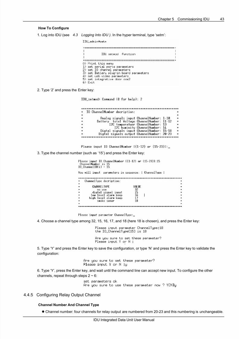
8/6/2019 IDU User Manual
http://slidepdf.com/reader/full/idu-user-manual 47/68
Chapter 5 Commissioning IDU 43
IDU Integrated Data Unit User Manual
How To Configure
1. Log into IDU (see 4.3 Logging Into IDU ). In the hyper terminal, type ‘setm’:
2. Type ‘2’ and press the Enter key:
3. Type the channel number (such as ‘15’) and press the Enter key:
4. Choose a channel type among 32, 15, 16, 17, and 18 (here 18 is chosen), and press the Enter key:
5. Type ‘Y’ and press the Enter key to save the configuration, or type ‘N’ and press the Enter key to validate the
configuration:
6. Type ‘Y’, press the Enter key, and wait until the command line can accept new input. To configure the other
channels, repeat through steps 2 ~ 6:
4.4.5 Configuring Relay Output Channel
Channel Number And Channel Type
z Channel number: four channels for relay output are numbered from 20-23 and this numbering is unchangeable.

8/6/2019 IDU User Manual
http://slidepdf.com/reader/full/idu-user-manual 48/68
44 Chapter 4 Commissioning IDU
IDU Integrated Data Unit User Manual
z Channel type: no use, digital signal output
How To Configure
1. Log into IDU (see 4.3 Logging Into IDU ). In the hyper terminal, type ‘setm’:
2. Type ‘2’ and press the Enter key:
3. Type the channel number (such as ‘20’) and press the Enter key:
4. Choose a channel type between 32 and 48 (here 32 is chosen), and press the Enter key:
5. Type the pulse bandwidth (such as ‘1’), and press the Enter key, or just press the Enter key to use the default value
(0):
6. Type ‘Y’ and press the Enter key to save the configuration, or type ‘N’ and press the Enter key to validate the
configuration:
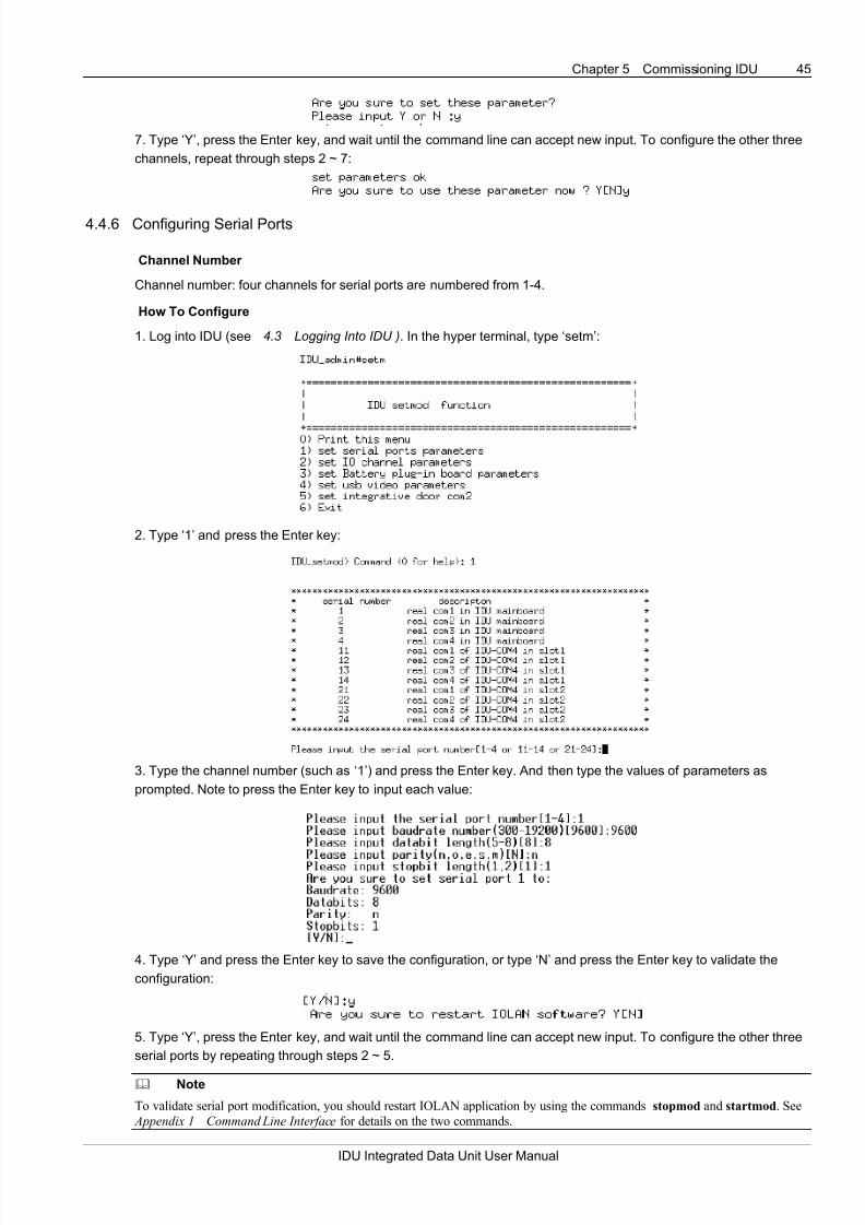
8/6/2019 IDU User Manual
http://slidepdf.com/reader/full/idu-user-manual 49/68
Chapter 5 Commissioning IDU 45
IDU Integrated Data Unit User Manual
7. Type ‘Y’, press the Enter key, and wait until the command line can accept new input. To configure the other three
channels, repeat through steps 2 ~ 7:
4.4.6 Configuring Serial Ports
Channel Number
Channel number: four channels for serial ports are numbered from 1-4.
How To Configure
1. Log into IDU (see 4.3 Logging Into IDU ). In the hyper terminal, type ‘setm’:
2. Type ‘1’ and press the Enter key:
3. Type the channel number (such as ‘1’) and press the Enter key. And then type the values of parameters as
prompted. Note to press the Enter key to input each value:
4. Type ‘Y’ and press the Enter key to save the configuration, or type ‘N’ and press the Enter key to validate the
configuration:
5. Type ‘Y’, press the Enter key, and wait until the command line can accept new input. To configure the other three
serial ports by repeating through steps 2 ~ 5.
Note
To validate serial port modification, you should restart IOLAN application by using the commands stopmod and startmod. See
Appendix 1 Command Line Interface for details on the two commands.

8/6/2019 IDU User Manual
http://slidepdf.com/reader/full/idu-user-manual 50/68
46 Chapter 4 Commissioning IDU
IDU Integrated Data Unit User Manual
Start Integrative Door (Optional)
COM2 can connect an integrative door. The system by default disables this function. To start this function, input
‘setmod’ or ‘setm’ under IDU_admin#.
Type ‘5’ and press the Enter key.
Input ‘3’, and as the system prompts to restart IOLAN, input ‘Y’.
After IOLAN restarts, the function of connecting integrative door is started.
4.4.7 Configuring IDU-BAT Channels
Channel Number And Channel Type
z Channel number: 55 channels are provided by an IDU-BAT and are numbered from 1-55, which is
unchangeable.
z Channel type: channels 1 ~ 24 and 31 ~ 54 can be set to no use, or dc voltage signal (default); channels 25 and
55 can be set to no use, dc voltage signal, or dc current signal (default).
How To Configure
1. Log into IDU (see 4.3 Logging Into IDU ). In the hyper terminal, type ‘setm’:

8/6/2019 IDU User Manual
http://slidepdf.com/reader/full/idu-user-manual 51/68
Chapter 5 Commissioning IDU 47
IDU Integrated Data Unit User Manual
2. Type ‘3’ and press the Enter key:
3. Type the number of the slot (1 or 2) where the IDU-BAT resides . If IDU-BAT card is inserted into slot 1, input “1”. If
IDU-BAT card is inserted into slot 2, input “2”.
4. Type the channel number (such as ‘25’) and press the Enter key:
5. Choose a channel type among 1, 2, and 32 (here 1 is chosen), and press the Enter key:
6. Type the values of x0, y0, x1, y1 (adjacent numbers are separated by a comma, and the default values are 0,0,1,1),
and press the Enter key:

8/6/2019 IDU User Manual
http://slidepdf.com/reader/full/idu-user-manual 52/68
48 Chapter 4 Commissioning IDU
IDU Integrated Data Unit User Manual
7. Type ‘Y’ and press the Enter key to save the configuration, or type ‘N’ and press the Enter key to validate the
configuration:
8. Type ‘Y’, press the Enter key, and wait until the command line can accept new input. To configure the other
channels, repeat through steps 2 ~ 8:
Note
After all parameters are configured, you can logout the hyper terminal manually, or the system will automatically log out if no
operation is made within a preset period.
4.5 Commissioning IDU With Tools99
This section describes how to commission IDU by using software.
4.5.1 Overview
Tools99 is developed by Emerson and is used to commission IDU. It can control the output and obtain data of IDU,IDU-BRG, IDU-BAT, IO channels, and user equipment.
Note that the computer should connect to IDU through network port.
4.5.2 Installing And Starting Tools99
Just copy Tools99.exe to a directory. Start Tools99 by double-clicking its icon.
4.5.3 Preparation
Double-click the icons of Tools99 and do as shown in Figure 4-11.

8/6/2019 IDU User Manual
http://slidepdf.com/reader/full/idu-user-manual 53/68
Chapter 5 Commissioning IDU 49
IDU Integrated Data Unit User Manual
1. Select DLLTEST tab
2. Select TCP/IP tab
3. Select Use IP Address
4. Select Terminal Server
Figure 4-11 Initial setting
Ports And Address
Ports
1. COM1 to COM4 of IDU correspond to ‘5001’, ‘5002’, ‘5003’, and ‘5004’, respectively.
2. IDU corresponds to ‘5005’.
3. IDU-IO equipment corresponds to ‘5006’.
4. Slots 1 and 2 correspond to start port ‘5011’ and ‘5021’, respectively.
Address
1. IDU and IDU-IO equipment do not need addresses.
2. See 4.5.6 Testing IDU-BAT for addresses of IDU-BAT
4.5.4 Testing IDU-IO
Do as shown in Figure 4-12 to test IO channels (port number: 5006).
1. Click Search File button to load
IDUIO.DLL
2. Enter IP address of IDU (port
No. 5006)
3. Click Connect Server button; when
connected, click Single Test button or
Acquire Data Uninterruptedly button
Single Test button
Acquire Data
Uninterruptedly button
Figure 4-12 Testing IDU-IO

8/6/2019 IDU User Manual
http://slidepdf.com/reader/full/idu-user-manual 54/68
50 Chapter 4 Commissioning IDU
IDU Integrated Data Unit User Manual
4.5.5 Tesing Control Function
Do as shown in Figure 4-13 to test the control function.
1. Select Control tab
2. Enter values in Control Parameters field
and Setting field
3. Click Control button and click OK on
the popup box
Figure 4-13 Tesing control function
4.5.6 Testing IDU-BAT
Do as shown in Figure 4-14to test the control function (port number: 5011 or 5021).
1. Click Search File button to load
IDUBAT.DLL
3. Enter IP address of IDU (port No.
5011 or 5021)
4. Click Connect Server button; whenconnected, click Single Test button or
Acquire Data Uninterruptedly button
Single Test button
Acquire Data
Uninterruptedly button
2. Enter the correct
address in Equipment
Address field
Figure 4-14 Testing IDU-BAT
Note
Equipment address: 11 is for the first battery group in slot 1; 12 is for the second battery group in slot 1; 21 is for the first battery
group in slot 2; 22 is for the second battery group in slot 1.

8/6/2019 IDU User Manual
http://slidepdf.com/reader/full/idu-user-manual 55/68
Chapter 5 Commissioning IDU 51
IDU Integrated Data Unit User Manual
4.5.7 Testing Serial Ports
Do as shown in Figure 4-15 to test the control function (port number: varies with actual situation).
1. Click Search File button to the
relevant DLL file
2. Enter IP address of IDU and the
port number
3. Click Connect Server button; whenconnected, click Single Test button or
Acquire Data Uninterruptedly button
Single Test button
Acquire Data
Uninterruptedly button
Figure 4-15 Testing serial ports
Note
1. COM1 to COM4 of IDU correspond to ‘5001’, ‘5002’, ‘5003’, and ‘5004’, respectively.
2. When residing in slot 1, COM1 to COM4 of IDU-COM4 correspond to ‘5011’, ‘5012’, ‘5013’, and ‘5014’, respectively.
3. When residing in slot 2, COM1 to COM4 of IDU-COM4 correspond to ‘5021’, ‘5022’, ‘5023’, and ‘5024’, respectively.
4.5.8 Testing IDU
Do as shown in Figure 4-16 to test the control function (port number: 5005).
1. Click Search File button to load
IDUHOST.DLL
2. Enter IP address of IDU (port No.
5005)
3. Click Connect Server button; when
connected, click Single Test button or
Acquire Data Uninterruptedly button
Single Test button
Acquire Data
Uninterruptedly button
Figure 4-16 Testing IDU
4.5.9 Quitting Tools99
To quit Tools99, just click the Close button.

8/6/2019 IDU User Manual
http://slidepdf.com/reader/full/idu-user-manual 56/68
52 Chapter 4 Commissioning IDU
IDU Integrated Data Unit User Manual
4.6 Upgrading Iolan Application
Note
Upgrade the Iolan application under instruction of Emerson technical support specialists.
Procedure
Step 1: Log into IDU as ‘iduadmin’
Step 2: Stop iolan application
1. Type ‘stopmod’ under IDU_admin#:
2. Type ‘2’.
3. After iolan application stops, type ‘3’.
Step 3: Download iolan application.
1. Type ‘download’ under IDU_admin#:
2. Type ‘2’:
3. Press the Enter key and type ‘Y’:

8/6/2019 IDU User Manual
http://slidepdf.com/reader/full/idu-user-manual 57/68
Chapter 5 Commissioning IDU 53
IDU Integrated Data Unit User Manual
4. In the hyper terminal, select Transfer -> Send File. The following dialog box is displayed.
Figure 4-17 Send file dialog box
5. In the Send File dialog box, click Browse, choose the iolan application, click Send, and wait until the download is
complete.
Step 4: After the iolan application is downloaded, start the iolan application (or restart IDU).
1. Type ‘startmod’ under IDU_admin#:
2. Type ‘2’.
The iolan application is upgraded successfully.

8/6/2019 IDU User Manual
http://slidepdf.com/reader/full/idu-user-manual 58/68
54 Chapter 5 Common Troubleshooting
IDU Integrated Data Unit User Manual
Chapter 5 Common Troubleshooting
The chapter introduces the methods to deal with malfunctions.
Symptom 1: The Power Indicator Remains Off After IDU Is Powered Up
Troubleshooting suggestion:
z Check the connection of power cables.
z Use a multimeter to measure if the input power voltage is at the required value.
Symptom 2: RS232 Port Failure
Troubleshooting suggestion:
z Check the wiring of sensors.
z Confirm that the baudrate is correctly set.
z Confirm that the IDU IP address is correctly set.
Symptom 3: RS232 Port Is Normal, But RS422/RS485 Port Fails
Troubleshooting suggestion:
Check if the cables are connected as follows:
RS422 mode
TX+ connects to R+
TX- connects to R-
RX+ connects to T+
RX- connects to T-
RS485 mode
DATA+ connects to T+
DATA- connects to T-
Symptom 4: No Data Is Collected By IDUBAT Dynamic Library
Troubleshooting suggestion:
z Check whether the equipment address is correctly set.
z Check whether the port number of the equipment is correctly set.
Symptom 5: Data From IDU-AI Channels And IDU-BAT Channels Are Inaccurate
Troubleshooting suggestion:
z Check the base voltage and adjust it to the proper value range if necessary.
z Check the jumpers and the channel types are correctly set.
Symptom 6: IDU Network Connection Fails
Troubleshooting suggestion:
z Check if IDU is in the same network segment as the device directly connected to it.
z Check if there is a gateway is present.
Symptom 7: No Data Can Be Gathered By The Serial Ports
Troubleshooting suggestion: check the setting of the baud rate and jumpers.

8/6/2019 IDU User Manual
http://slidepdf.com/reader/full/idu-user-manual 59/68
Chapter 6 Technical Specification 55
IDU Integrated Data Unit User Manual
Chapter 6 Technical Specification
This chapter lists technical specifications of IDU, and other parts.
6.1 Specification Of IDU
Table 6-1 Specification of IDU
Item Description
Slot Two: slot1, slot2
Port
One network port
One CONSOLE port
One USB port
Four serial ports
Ten analog input port
two battery group total voltage channels
One THS portOne power port
Four relay output ports
Size (W x D x H) (mm) 440±1mm x 295±1mm x 44±1mm
Weight Host weight: ≤5kg
input voltage IDU input power supply: 20Vdc ~ 60Vdc
6.1.1 Input Parameters
Table 6-2 Input parameters of CH1 ~ CH14
Input portMeasurement
precision
Input Remark
CH1 ~
CH10
Error < 0.5% of
full measurement
range
4 ~ 20mA current or 0 ~
10V voltage
Capable of measuring digital signal and analog signal.
Channels 1 ~ 6 are by default for 4 ~ 20mA, channels 7 ~ 10 are
by default for 0 ~ 10V (can be fed with digital signal too)
The above channels can be changed through jumpers to meet the
need to connect sensors
CH11 and
CH12
Error < 1% of full
measurement
range
18 ~ 60Vdc
IDU can be fed with battery group voltage with no need for DC
transformer.
The two channels are decidated
±2 ºC TemperatureCH13 and
CH14±5%(25ºC) Humidity
The two channels are decidated
Table 6-3 Input parameters of CH15 ~ CH18
Input port Input Description
CH15 Connecting to smoke sensor
CH16 Connecting to water sensor
CH17 Connecting to door status sensor
CH18 Connecting to infrared sensor
These channels are by default fixed, but, with software, they can be
configured to input other sensor signals by maintenance engineers. However,
it is not recommended to re-configure these channels as they are labeled.
The smoke channel has false alarm clearing function.

8/6/2019 IDU User Manual
http://slidepdf.com/reader/full/idu-user-manual 60/68
56 Chapter 6 Technical Specification
IDU Integrated Data Unit User Manual
6.1.2 Output Parameters
Table 6-4 Output parameters of IDU
Output parameter Value Function
Number of outputs 4
Output contacts Relay normally open contactRelay output
parameters
Contact capacity 1A/30Vdc
4 relays can be controlled
independently
+ 12V output 11.8 ~ 13.2V. Max. output current: 0.2ASensor power
output
parameters+ 24V output 21.6 ~ 26.4V. Max. output current: 0.4A
The output current here is the total
current that the sensor power source
can provide
6.2 Specification Of IDU-BRG1/IDU-BRG2
6.2.1 Communication Ports
Two 10/100M, half/full-duplex, adaptive Ethernet ports, with automatic cable-cross function, RJ45 connectors.
Two E1 ports (for WAN) support framing/non-framing mode, main clock/link clock sending mode, supportive of 75Ω
and 120Ωmodes, capable of bidirectional ring networking, DB15 interface with BNC DB15 cables.
Data can be exchanged between the four ports through an internal data exchange mechanism.
Table 6-5 lists the attributes of the communication ports.
Table 6-5 Communication port attributes
Item Requirement
Electrical characteristics Comply with ITU-T G..703
Link type HDB3
Data rate 2.048M bit/s
Basic frame format Comply with ITU-T G.704
Port resistance 75Ω/120Ω
Clock tremble and float Comply with ITU-T I.431 and ITU-T G.703Threshold of signal loss detection Comply with ITU-T G.775
Sending clock Line clock or internal clock
Nominal precision of the internal clock ±50ppm (20ºC)
6.3 Specification Of IDU-BAT1/IDU-BAT2
6.3.1 Performance
Measurement precision: better than +/- 0.2% FS (that is, for 2V battery: +/- 5mV; for 6V battery: +/-15mV; for 12V
battery: +/-30mV)
Data collecting speed: less than 5s for a battery group
6.3.2 Ports Specification
Table 6-6 Ports specification
Battery group Ports Input Remark
CH1 ~ CH24 2V/6V/12V voltage Maximal input voltage: 30Vdc
1CH25 0 ~ 10V voltage or 4 ~ 20mA current
Maximal input voltage: 30Vdc
Maximal input current: 32mA
CH31 ~ CH54 2V/6V/12V voltage Maximal input voltage: 30Vdc
2CH55 0 ~ 10V voltage or 4 ~ 20mA current
Maximal input voltage: 30Vdc
Maximal input current: 32mA

8/6/2019 IDU User Manual
http://slidepdf.com/reader/full/idu-user-manual 61/68
Chapter 6 Technical Specification 57
IDU Integrated Data Unit User Manual
6.4 Specification Of IDU-COM4
6.4.1 Communication Ports
z Provides four serial ports; the first port conforms to RS-422/485/232; the second port conforms to RS422/485;
the third port conforms to RS232/RS485/232; the fourth port conforms to RS232.z Baudrate: 1200bps, 2400bps, 4800bps, 8000bps, 9600bps, 19200bps.
zWord length: 5 to 8 bits.
z Parity check: N, odd, even, M, or S.
z Stopbit: ½ bit.
z Supporting pluggable connector.
6.5 Sensors
Table 6-7 Specification of sensors
Sensor Operating principle Type Specification
Smoke
sensor
The smoke sensor sends off
radials produced by
radioelement, and these radials
help detect smoke
JTY-LZ-983K
Operating voltage: 18 ~ 24Vdc
Output signal: current
Operating current: maximum 12mA (when alarms are
raised)
SJ516B
Operating voltage: 12Vdc (±5%)
Operating current: 30mA (Max)
Maximum operating current: 40mA (Max) (when alarms are
raised)
Relay capacity: 1A/30Vdc, 0.3A/110Vdc, or 0.5A/125Vdc
Water level when alarm is raised:3±1mm
Output: NO when no alarms are generated
Operating temperature: –10°C ~ +60°C
Cable length: 5mWater sensor
When the photoelectrical detector
immerges into water, the water
sensor will generate alarms
SJ516C
Operating voltage: 24Vdc (±5%)
Operating current: 30mA (Max)
Maximum operating current: 40mA (Max) (when alarms are
raised)
Relay capacity: 1A/30Vdc, 0.3A/110Vdc, or 0.5A/125Vdc
Water level when alarm raised: 3±1mm
Output: NO when no alarms are generated
Operating temperature: –10°C ~ +60°C
Cable length: 5m
Door status
sensor
The door status sensor consists
of magnetic contacts (made of
Ferrite core)
The magnetic contacts have two
parts, which will attach to each
other within certain distance and
detach from each other beyond
that distance
MC-58 (madeof iron for
metal doors)
Operable range: from detachment to attachment > 40mm;
from attachment to detachment < 65mm
Contact capacity: 100Vdc, 0.1A
Transmission: 200m

8/6/2019 IDU User Manual
http://slidepdf.com/reader/full/idu-user-manual 62/68
58 Chapter 6 Technical Specification
IDU Integrated Data Unit User Manual
Sensor Operating principle Type Specification
Infrared
senor
The infrared sensor is based on
the pyroelectric effect. It is
powered by 12V and can detect
microwave and infrared. By DIP
switches, the sensitivity of the
sensor can be configured. (See
its manual for details.)
During the 3 minutes immediately
following power-up, the sensor
will not generate any alarms; after
that period, the sensor start
functioning, which means it will
generate alarms when anybody
moves in the equipment room
MC-760T
Power supply: 12Vdc
Output: dry contact
Detection range: 10 ~ 15m
Operating current: 30mA
THS
The THS adopts the patented
CMOSens techniques to provided
digital output. It communicates
with the MCU through a serial
port to get the correction error
and temperature and humidity
data
PXS-TH10-12
Power supply: 5±0.5Vdc
Operating current: less than 10mA
Measurement range: temperature –10°C ~ 50°C; humidity 5
~95%RH
Precision: temperature ±2°C; humidity ±5%RH
Cable length: 1 m, pluggable with 5pin (3.81mm)
connector
6.6 Environmental Requirement
Table 6-8 Environmental requirement for IDU operation
Item Requirement
Where to use For indoor use
Ambient temperature -10ºC ~ +50ºC
Relative humidity 5% ~ 95%RH (no condensation)
Air cleanness Comply with indoor requirements in GR-63No corrosive or flammable gases, no oily mist, steam, water drops, or salt
Air pressure 70 ~ 106Kpa
Storage temperature -40ºC ~ +70ºC
Cooling mechanism Natural cooling
Protection level IP20
Transport requirement See Table 6-9
Remark
The ambient temperature applies to IDU, and ensure the sensors will not be damaged under such temperature
Note
The temperature and humidity is measured at a position 1.5 meters above the floor and 0.4 meter from the IDU, with IDU not
equipped with protection board.
6.7 Transport Requirement
Table 6-9 IDU transport requirement
Sine vibration
testing
ETS300 019-2-3
T2.3; IEC68-2-6
5 ~ 9Hz, 3.5mm
9 ~ 200Hz, 10m/s2
200 ~ 500Hz, 15m/s2
30 minutes in each direction (3 directions in all)
No wrapping or electricity
Random packing
vibration
GB/T 14508,2MR2
IEC68-2-34
5 ~ 10Hz: 10m2/s
3
10 ~ 200Hz: 1m2
/s3
30 minutes in each direction (3 directions in all)
Package
drop-test
ETS 300-019-2-2 T2.3,
IEC69-2-32
100cm
Once for each of the 6 sides

8/6/2019 IDU User Manual
http://slidepdf.com/reader/full/idu-user-manual 63/68
Chapter 6 Technical Specification 59
IDU Integrated Data Unit User Manual
6.8 Mechanical Specification
Table 6-10 Mechanical specification of IDU parts
Item Dimensions Weight
IDU 440±1mm×295±1mm×44±1mm ≤5kg
IDU-BAT1 122±1mm×185±1mm×1.6mm ≤0.5kg
IDU-BAT2 122±1mm×185±1mm×1.6mm ≤0.5kg
IDU-BRG1 122±1mm×185±1mm×1.6mm ≤0.5kg
IDU-BRG2 122±1mm×185±1mm×1.6mm ≤0.5kg
IDU-COM4 122±1mm×185±1mm×1.6mm ≤0.5kg

8/6/2019 IDU User Manual
http://slidepdf.com/reader/full/idu-user-manual 64/68
60 Appendix 1 Command Line Interface
IDU Integrated Data Unit User Manual
Appendix 1 Command Line Interface
These command lines of this appendix are only used of IDU with IOLAN.
1. Overview
In command line mode, the user can run commands to configure and manage the equipment. The command line
provides:
z Local configuration function through Console port
z Command line editing
z Online help information
z Network diagnosis help
z Command recognition: the user need only input part the key word related to a command and the shell can
recognize the command, for example, to run the command download, just type 'down’.
2. Starting Command Line
Note
Command operations described in this section are made in the case that hyper terminal is used to log into IDU. The user can also
use another software (such as SecureCRT4.1) to log into IDU and perform the same operations.
In the command line interface, use the user name ‘iduadmin’ and password ‘iduadmin’ for login.
Figure 1 Command line main screen
If no operation is performed in a preset period, the system will automatically log out.
Note
1. The user iduadmin has a lower privilege and thus can perform fewer operations.
3. Commonly Used Commands
(1) help (?)
This command is used to get help information:

8/6/2019 IDU User Manual
http://slidepdf.com/reader/full/idu-user-manual 65/68
Appendix 1 Command Line Interface 61
IDU Integrated Data Unit User Manual
Figure 2 Help information
(2) setip
Run this command to configure network data:
Figure 3 Setip screen
You should enter IP address and subnet mask according to system prompt.
This modification can take effect immediately.
(3) saveip
This command saves the network configuration data.
Figure 4 Saveip screen
If you decide to save the network configuration, type y, or else type n
(4) download
This command is used to download files:
Figure 5 Download menu
z Type ‘0’ and press the Enter key: show download menu
z Type ‘1’ and press the Enter key: download software package (*.tar.gz) (with recommended size of no more than
2M) to the directory /IDU; the older homonymic file will be overwritten
z Type ‘2’ and press the Enter key: download files to a specified directory (older homonymic file will be
overwritten.)
z Type ‘3’ and press the Enter key: clear the contents in the directory /IDU

8/6/2019 IDU User Manual
http://slidepdf.com/reader/full/idu-user-manual 66/68
62 Appendix 1 Command Line Interface
IDU Integrated Data Unit User Manual
z Type ‘4’ or ‘q’ and press the Enter key: exit
If no key is stroked in a preset period, the system will automatically return to the command line main interface.
Note
1. If the user logs into the IDU through a remote terminal or Hyper terminal, and 1 or 2 is selected, the system will display “ready.
Type sz file ..." to your modem program. And then the user can choose a file to download by selecting Send > Send File and
send the file using the zmodem protocol
2. If the user logs into the IDU through RS232 serial port, the user can download files through IDU configuration port; if the user logs into the IDU through a remote terminal, the user can download files through Ethernet port. It is recommended to use a
network that offers a high speed.
3. After a file is downloaded, upload the file to check if the download is successful.
(5) viewdata
This command shows the data of IO channels and BAT boards.
Figure 6 Viewdata menu
z Type ‘0’ and press the Enter key: show viewdata menu
z Type ‘1’ and press the Enter key: show the data of IO channels, including channels 15–18 and 1–12
z Type ‘2’ and press the Enter key: show data of BAT boards
z Type ‘3’ and press the Enter key: show data of relays
z Type ‘4’ or ‘q’ and press the Enter key: exit
If no key is stroked in a preset period, the system will automatically return to the command line main interface.
(6) lookstatus
This command shows various statuses:
Figure 7 Lookstatus menu
z Type ‘0’ and press the Enter key: show lookstatus menu
z Type ‘1’ and press the Enter key: show system status
z Type ‘2’ and press the Enter key: show network status
z Type ‘3’ and press the Enter key: show slot status
z Type ‘4’ or ‘q’ and press the Enter key: exit
If no key is stroked in a preset period, the system will automatically return to the command line main interface.
(7) startmod
This command starts the iolan application and DHCP service.

8/6/2019 IDU User Manual
http://slidepdf.com/reader/full/idu-user-manual 67/68
Appendix 1 Command Line Interface 63
IDU Integrated Data Unit User Manual
Figure 8 Startmod menu
z Type ‘0’ and press the Enter key: show startmod menu
z Type ‘1’ and press the Enter key: start iolan application
z Type ‘2’ and press the Enter key: start DHCP client service
z Type ‘3’ or ‘q’ and press the Enter key: exit
If no key is stroked in a preset period, the system will automatically return to the command line main interface
Note
1. Upon the first startup of the system, a static IP address is assigned to the system, with DHCP disabled. Once the DHCP is
started, a dynamic IP address is obtained each time the system starts. You can disable DHCP with the command stopmod.
2. Directly pressing Enter will leave the previous value unchanged.
(8) stopmod
This command stops iolan application and DHCP.
Figure 9 Stopmod menu
z Type ‘0’ and press the Enter key: show stopmod menu
z Type ‘1’ and press the Enter key: stop iolan application
z Type ‘2’ and press the Enter key: stop DHCP client service
z Type ‘3’ or ‘q’ and press the Enter key: exit
If no key is stroked in a preset period, the system will automatically return to the command line main interface
(9) setmod
See Chapter 5 Data Configuration for details about this command.
Figure 10 Setmod menu
If no key is stroked in a preset period, the system will automatically return to the command line main interface
Note
After parameter configuration, press Y as the system prompts whether to use these parameters. This will cause the modification
to take effect in few seconds (the time varies according to the number of battery groups).
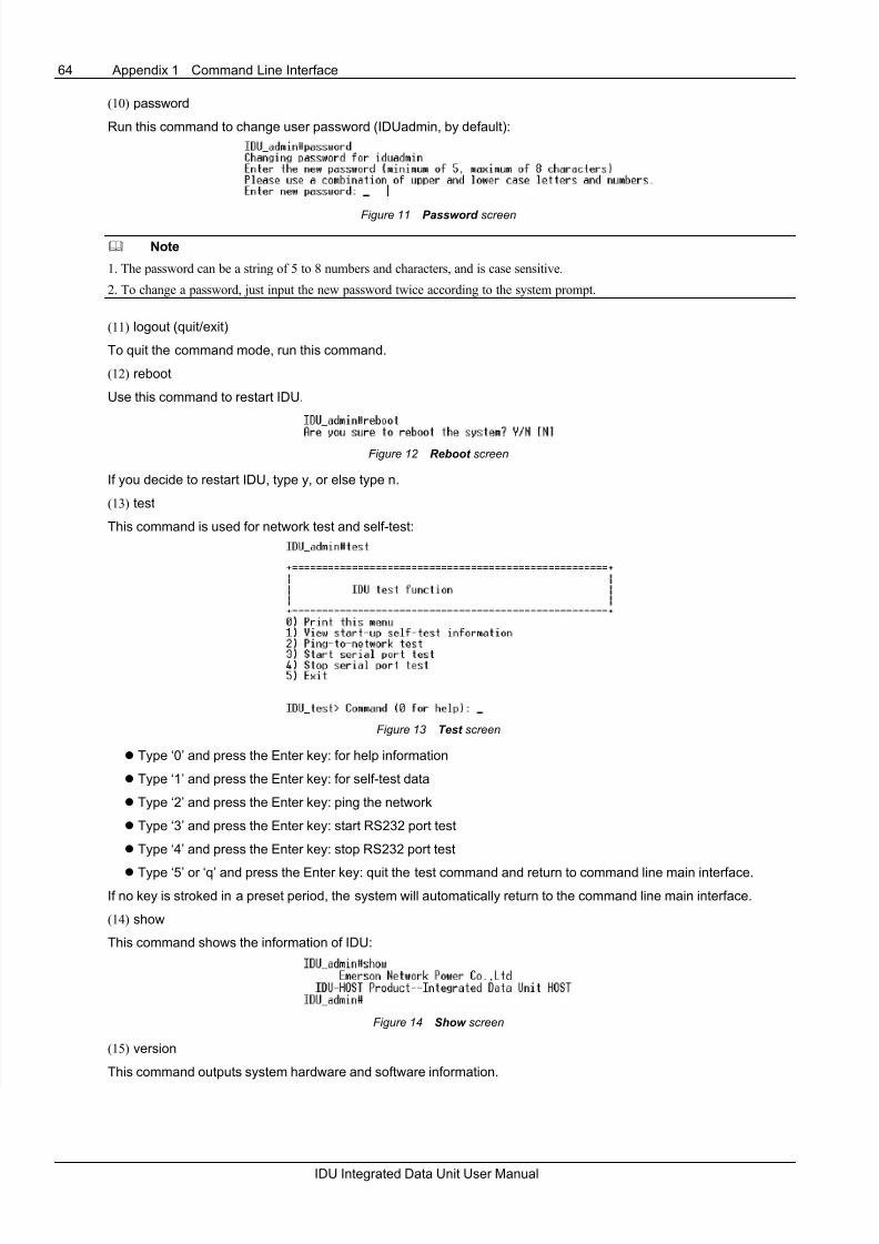
8/6/2019 IDU User Manual
http://slidepdf.com/reader/full/idu-user-manual 68/68
64 Appendix 1 Command Line Interface
(10) password
Run this command to change user password (IDUadmin, by default):
Figure 11 Password screen
Note
1. The password can be a string of 5 to 8 numbers and characters, and is case sensitive.
2. To change a password, just input the new password twice according to the system prompt.
(11) logout (quit/exit)
To quit the command mode, run this command.
(12) reboot
Use this command to restart IDU.
Figure 12 Reboot screen
If you decide to restart IDU, type y, or else type n.
(13) test
This command is used for network test and self-test:
Figure 13 Test screen
z Type ‘0’ and press the Enter key: for help information
z Type ‘1’ and press the Enter key: for self-test data
z Type ‘2’ and press the Enter key: ping the network
z Type ‘3’ and press the Enter key: start RS232 port test
z Type ‘4’ and press the Enter key: stop RS232 port test
z Type ‘5’ or ‘q’ and press the Enter key: quit the test command and return to command line main interface.
If no key is stroked in a preset period, the system will automatically return to the command line main interface.
(14) show
This command shows the information of IDU: