

SGS Prime COGO - CalcsPlus
166
SGS PRIME COGO Version 1.9.3 - Reference Manual December 29, 2020 https://sgss.ca/
Transcript of SGS Prime COGO - CalcsPlus

1
1 Installation .............................................................................................................................. 6 New Installation ................................................................................................................................... 6
Upgrade to new Version ...................................................................................................................... 8
Running SGS Prime COGO ............................................................................................................... 10
License Key ....................................................................................................................................... 11
2 Main Menu and User Interface ............................................................................................ 12 Main Menu Screen ............................................................................................................................. 12
About Screen ..................................................................................................................................... 14
Project Manager Shortcut .................................................................................................................. 14
User Settings Shortcut ....................................................................................................................... 15
Points Database Shortcut .................................................................................................................. 15
Keyboard ........................................................................................................................................... 17
Input Forms ....................................................................................................................................... 18
Copy and Paste ................................................................................................................................. 18
Touchscreen keypads ........................................................................................................................ 19
Point IDs ............................................................................................................................................ 20
Point Ranges ..................................................................................................................................... 20
Directions .......................................................................................................................................... 20
Angles ............................................................................................................................................... 21
Distances ........................................................................................................................................... 21
Coordinates ....................................................................................................................................... 22
Stations ............................................................................................................................................. 22
Grades ............................................................................................................................................... 22
Text ................................................................................................................................................... 22
Choose Lists ...................................................................................................................................... 23
Checkboxes ....................................................................................................................................... 23
Choose Boxes ................................................................................................................................... 24
Output Screens .................................................................................................................................. 24
3 User Settings ........................................................................................................................ 25 Angle and Distance Units................................................................................................................... 25
Angle Unit .......................................................................................................................................... 25
Angle Precision .................................................................................................................................. 25
Direction Reference ........................................................................................................................... 25
Distance Unit ..................................................................................................................................... 26
Distance Precision ............................................................................................................................. 26
Secondary Unit .................................................................................................................................. 26
Display Secondary Unit ..................................................................................................................... 26
Foot Definition ................................................................................................................................... 26
Foot Display ....................................................................................................................................... 26
Coordinates, Stations and Grades ..................................................................................................... 27

2
Coordinate Display ............................................................................................................................ 27
Coordinate Precision ......................................................................................................................... 27
Stationing Display .............................................................................................................................. 27
Stationing Precision ........................................................................................................................... 27
Grade Display .................................................................................................................................... 27
Grade Precision ................................................................................................................................. 27
Input and Output Scale Factors ......................................................................................................... 28
Input Scale Factor.............................................................................................................................. 28
Apply Input Scale Factor .................................................................................................................... 28
Inverse? ............................................................................................................................................. 28
Output Scale Factor ........................................................................................................................... 28
Apply Output Scale Factor ................................................................................................................. 28
Program Options ............................................................................................................................... 29
Radius Tolerance............................................................................................................................... 29
Time/Date .......................................................................................................................................... 29
Auto Exit Time ................................................................................................................................... 29
Clipboard Size ................................................................................................................................... 29
DXF File Layers ................................................................................................................................. 29
Coordinate System ............................................................................................................................ 30
Projection .......................................................................................................................................... 30
Radius Method .................................................................................................................................. 31
Earth Radius ...................................................................................................................................... 32
Vertical System .................................................................................................................................. 32
Average Geoid Height ....................................................................................................................... 32
User Defined Coordinate Systems ..................................................................................................... 32
User Defined Ellipsoids ...................................................................................................................... 33
Terminology Localization ................................................................................................................... 33
Settings Use and Application ............................................................................................................. 34
4 COGO Menu .......................................................................................................................... 35 Point Traverse 2D .............................................................................................................................. 35
Point Traverse - Standard .................................................................................................................. 36
Point Traverse – Angle Right ............................................................................................................. 37
Point Traverse – Plus ........................................................................................................................ 37
Curve Traverse .................................................................................................................................. 41
Inverse Calculations .......................................................................................................................... 42
Inverse Points .................................................................................................................................... 42
Inverse Curve .................................................................................................................................... 47
Inverse Angle ..................................................................................................................................... 50
Inverse Point to Line .......................................................................................................................... 50
Inverse Point to Curve ....................................................................................................................... 51
Inverse Points to Alignment ............................................................................................................... 51
Intersections ...................................................................................................................................... 52
Bearing-Bearing ................................................................................................................................. 52

3
Bearing-Distance ............................................................................................................................... 53
Distance-Distance.............................................................................................................................. 54
Distance-Interior Angle ...................................................................................................................... 55
Areas / Closures ................................................................................................................................ 56
Area by Points ................................................................................................................................... 56
Subdivide by Sliding Direction ........................................................................................................... 58
Subdivide by Hinge Point ................................................................................................................... 59
Closures ............................................................................................................................................ 60
Quick Closure .................................................................................................................................... 64
Fit Points ........................................................................................................................................... 68
Fit to Straight Line.............................................................................................................................. 68
Fit to Circular Curve ........................................................................................................................... 70
Double Proportion .............................................................................................................................. 72
Irregular Boundary Adjustment .......................................................................................................... 74
Grant Boundary Adjustment ............................................................................................................... 76
5 Adjust Menu.......................................................................................................................... 77 Compass Rule ................................................................................................................................... 77
Closed Figure .................................................................................................................................... 77
Close to Fixed Point ........................................................................................................................... 79
Rotate/Mirror Points ........................................................................................................................... 81
Rotate around Base Point .................................................................................................................. 81
Rotate around Origin (0,0) ................................................................................................................. 82
Mirror along Baseline ......................................................................................................................... 82
Shift/Average Points .......................................................................................................................... 83
Shift by ΔX/ΔY/ΔZ.............................................................................................................................. 83
Shift by Distance/Direction/ΔZ ........................................................................................................... 84
Shift by From/To Points ..................................................................................................................... 84
Average Points .................................................................................................................................. 85
Scale Points....................................................................................................................................... 86
Scale from Base Point ....................................................................................................................... 86
Scale from Origin (0,0,0) .................................................................................................................... 86
Transform Coordinates ...................................................................................................................... 87
Helmert Transformation ..................................................................................................................... 87
3D to Plan Cross Section ................................................................................................................... 90
6 Tools Menu ........................................................................................................................... 91 Triangle Solver .................................................................................................................................. 91
Horizontal Curves .............................................................................................................................. 92
Circular Curve Solver ......................................................................................................................... 92
Curve Through Fixed Point ................................................................................................................ 96
Spiral Curve Solver ............................................................................................................................ 97
Vertical Curves .................................................................................................................................. 99
Grades and Length known ............................................................................................................... 100
Elevations and Length known .......................................................................................................... 101
Fixed Point, VPI and Grades known ................................................................................................ 102

4
Fixed Point, BVC and Grades known ............................................................................................... 103
Intersect Slopes from two known points ........................................................................................... 104
Solution Screen and Calculations .................................................................................................... 105
RPN Calculator ................................................................................................................................ 107
Main Interface .................................................................................................................................. 107
Menus .............................................................................................................................................. 109
Vector objects .................................................................................................................................. 110
Configure Settings ........................................................................................................................... 110
7 Points Menu ........................................................................................................................ 111 Store and Edit Points ....................................................................................................................... 111
Point ID ............................................................................................................................................ 111
Delete Points ................................................................................................................................... 112
Renumber Points ............................................................................................................................. 113
By Starting Number ......................................................................................................................... 113
By Additive Number ......................................................................................................................... 114
Plot Points ....................................................................................................................................... 115
Using Touch .................................................................................................................................... 115
Using the Keyboard ......................................................................................................................... 115
Using the Menu .............................................................................................................................. 115
Import/Export ................................................................................................................................... 116
Import Points ................................................................................................................................... 116
Export Points ................................................................................................................................... 117
Import Project .................................................................................................................................. 120
Export Project .................................................................................................................................. 120
8 Advanced Menu .................................................................................................................. 121 Alignments ....................................................................................................................................... 121
Alignment Manager .......................................................................................................................... 121
Defining an Alignment ...................................................................................................................... 122
Alignment Calculations .................................................................................................................... 132
Leveling ........................................................................................................................................... 135
Leveling Project Manager ................................................................................................................ 135
Working with a Leveling Project ....................................................................................................... 136
Traverse Plus 3D (BETA) ................................................................................................................ 142
Setup ............................................................................................................................................... 142
Measure .......................................................................................................................................... 148
Stake ............................................................................................................................................... 149
Reference ....................................................................................................................................... 154
Tools................................................................................................................................................ 157
Close ............................................................................................................................................... 157
Coordinate Converter ...................................................................................................................... 158
Grid↔Geodetic↔Cartesian ............................................................................................................. 158
Grid1→Grid2 (Single Point) ............................................................................................................. 159
Grid1→Grid2 (Convert Database) .................................................................................................... 160
Grid↔Ground (Single Point) ............................................................................................................ 161

5
Grid↔Ground (Convert Database) .................................................................................................. 162
Ellipsoid Calculations ....................................................................................................................... 163
DIRECT Computation ...................................................................................................................... 163
INVERSE Computation .................................................................................................................... 164
Appendix A ...................................................................................................................................... 165

SGS Prime COGO | Installation 6
Install the SGS Prime COGO application for HP Prime on any of the following devices:
► Physical HP Prime Graphing Calculators
► Virtual Calculators for Windows or Mac
► Windows UWP HP Prime Pro app
► Android HP Prime Pro app
► iOS HP Prime Pro app
Required: Installation requires the Connectivity Kit for Windows or Mac.
New Installation
Step Action
1 Download the installation files from https://sgss.ca/hpprime.html.
2 Unzip/extract the installation files.
3 Navigate into the folder where the files were extracted, a folder with the version number of the app will be found.
4 Open the folder to reveal a sub-folder with a .hpappdir extension inside.
5 Open the Connectivity Kit on your PC or Mac.
6 A. For physical HP Prime calculators; plug in the USB cable to connect. B. For HP Prime Pro apps; open the app on the device that is on the same Wi-Fi
network as the PC or Mac running the Connectivity Kit.
7 Confirm your calculator connection, it will be visible in the pane
of the Connectivity Kit once connected.

SGS Prime COGO | Installation 7
8 Expand the connected calculator in the Connectivity Kit.
Drag and Drop the
folder from Step 4 onto the
folder of your
calculator. It may take a few seconds to complete the transfer.
Close the Connectivity Kit.

SGS Prime COGO | Installation 8
Upgrade to new Version
To preserve application variables and files, it is best to overwrite only the program code of the app when
upgrading to a newer version. It is currently not possible to overwrite just the program code of an app
directly in the Application Library; therefore, a workaround step is required to accomplish the upgrade.
NOTE: When upgrading from Version 1.5.1 or later you can do the following to save a bit of time:
1. From within the app, use the Unload option to backup user data.
2. Delete the app from your calculator. (See Reset option in the Application Library with app selected)
3. Connect calculator to the Connectivity Kit and install like a new installation.
4. Run the app after installation and then use the Reload option to restore user data.
Step Action
1 Download the installation files from https://sgss.ca/hpprime.html.
2 Unzip/extract the installation files.
3 Navigate into the folder where the files were extracted, a folder
with the version number of the app will be found.
4 Open the folder to reveal a sub-folder with a .hpappdir
extension inside.
5 Open the Connectivity Kit on your PC or Mac.
6 A. For physical HP Prime calculators; plug in the USB cable to connect.
B. For HP Prime Pro apps; open the app on the device that is on the same Wi-Fi
network as the PC or Mac running the Connectivity Kit.
7 Confirm your calculator connection, it will be visible in the pane
of the Connectivity Kit once connected.
8 Expand the folder and
locate the app. Drag and drop
the app into the pane of
the Connectivity Kit.
This will create an SGS Prime COGO.hpappdir
folder in the Content pane as shown.

SGS Prime COGO | Installation 9
10 Right-click on the app in the
and choose Delete.
11 Using your PC or Mac File Explorer, open the folder from
Step 4.
Inside you will find a file, drag and drop this file onto the
folder in the pane.
At the prompt choose Yes to replace the file.
This updates the program code of the app in the Content pane.
12 Drag and Drop the folder from the
pane to the folder.
It may take a few seconds to complete the transfer.
Close the Connectivity Kit.

SGS Prime COGO | Installation 10
Running SGS Prime COGO
Once installed, run SGS Prime COGO by one of the following methods:
1. Open the Application Library on your calculator by
using the ! key. Locate the SGS Prime COGO
app and tap the icon or Start on the menu to open
the application.
or
2. From the Home or CAS screen, if SGS Prime
COGO is the active application with the title visible
at the top of the screen, use the N key to start
the application.
Other shortcut keys available from the Home or CAS
screen:
► @ starts the RPN Calculator.
► P opens the Plot Points program.
► S and @ / P / N opens the User Settings options.

SGS Prime COGO | Installation 11
License Key
A valid License Key enables the functionality of the
software.
License Keys are bound to the Device ID of the
calculator or app that the SGS Prime COGO application
is installed on.
You must supply the Device ID of your calculator or app
when requesting a License Key.
The Device ID should match the calculator serial
number followed by a few characters to help identify the
type of device and the version of the app.
Contact [email protected] for more information about licensing.

SGS Prime COGO | Main Menu and User Interface 12
SGS Prime COGO is designed for touch and keyboard navigation.
Main Menu Screen
The user interface displays program settings and provides access to all program functions. The diagram
below illustrates the screen layout.
See the next two pages for descriptions of the various components.

SGS Prime COGO | Main Menu and User Interface 13
Item Description
Project Name
Displays the current project name and the number of points stored in the
current project.
NOTE: Tap on this area to display the About screen.
Shortcuts Often used functions are available on all main interface screens.
Current Project
Displays some of the available user settings.
► DMS (360° ‘ “) D.d° (360° decimal) GON (400 gons) indicates current
Angle Unit setting.
► |N (North Bearings) |S (South Bearings) |QB (Quadrant Bearings)
indicates current direction reference setting.
► Metres (Metres) IFeet (International Feet) USFeet (US Survey Feet)
indicates the current Distance Unit setting.
► Coordinate system and associated ellipsoid.
Menu Options
Displays the titles of all menus, with the active menu name highlighted.
► COGO menu
► Adjust menu
► Tools menu
► Points menu
► Advanced menu
Program
Selection
Displays the available programs within each menu, with the currently
selected program name highlighted.

SGS Prime COGO | Main Menu and User Interface 14
About Screen
Tap the top of the main menu to display the About
screen. The program version and license information is
shown.
Update License Key. This will be necessary
when upgrading an existing license from Lite to
Standard, or Standard to Professional.
Unload app data to reduce the memory size of
the app folder. Warning: This removes all user-created
content from the app and is intended for use prior to
performing an app upgrade to a new version.
Reload previously unloaded app data. Intended to be used immediately after performing an app
upgrade to a new version.
Project Manager Shortcut
Tap to access the Project Manager. Available options:
Create a new Project. The name is entered, and common user settings are selected. Some of
the User settings are stored with each project while others are applied to all projects; see the User
Settings chapter for details.
Delete the selected project. A confirmation prompt is displayed. The \ key also deletes.
Rename the selected project.
Load the selected project.

SGS Prime COGO | Main Menu and User Interface 15
User Settings Shortcut
Tap to access the User Settings. See the User Settings chapter.
Points Database Shortcut
Tap to access the current project Points Database.
Points are sorted in numerical ascending order.
Available options:
Edit the selected Point coordinates and
description.
Find a point by Point ID.
Page Down, scrolls to the next page until the
end of the database is reached.
Page Up, scrolls to the previous page until the
start of the database is reached.
The S key toggles display of the Elevation column, while the \ key deletes the selected point.
Find Points
Enter a Point ID to display the coordinates and description of the Point ID. Scroll to view information of
the adjacent points, as sorted numerically.
While viewing point information:
Edit the currently displayed point.
Exit the Find Points program and return to the Main Menu.

SGS Prime COGO | Main Menu and User Interface 16
Return to the Input Form.

SGS Prime COGO | Main Menu and User Interface 17
Keyboard
Navigate the main user interface by using the directional cursor keys. Use the L and R cursor keys
to change the current menu and use the U and D cursor keys to change the current selection.
► ~ will load the currently selected program.
► & or O will exit SGS Prime COGO.
► Numeric keys 1 through 5 can be used to run the corresponding program from each
menu.
► @ launches the RPN Calculator app from the Main Menu or from any Input Form.
► P opens the Plot Points program.
► V opens the Points Database.

SGS Prime COGO | Main Menu and User Interface 18
Input Forms
Input forms are used throughout the program to accept multiple different types of input. Some common
input types are: Point IDs / Point Ranges / Directions / Angles / Distances / Coordinates / Stations /
Grades / Text / Choose Lists / Checkboxes
Each input form will have some of the same basic elements, such as the Title, Field Labels, Input Fields,
Help Text and a Menu. Some input forms feature more than one page, the page selections can be made
on the right edge of the screen. The touch screen and keyboard can be used to select fields.
Current display settings control the appearance of each field.
NOTE: The RPN Calculator app can be launched from any input form by using the @ key.
Copy and Paste
The clipboard can hold multiple items, which are stored
as strings as would be entered into an input field.
S and V can be used to copy the value inside
the selected field, or the value being edited.
S and M can also be used to paste from the
clipboard.
The Copy/Paste functionality is a good method to
transfer calculated values to/from an Input Form and the RPN Calculator.

SGS Prime COGO | Main Menu and User Interface 19
Touchscreen keypads
When any editable input field is selected, tap on the field to open the touchscreen keypad to enter a
value. There are two types of keypads, numeric and alpha-numeric.
Numeric keypad
Any time a numeric field is edited, the numeric keypad
opens. The title of the keypad is the help text of the field
being edited, and a “helper” button is to the right of the
edit line, which can vary depending on the type of input
field you’re editing. The example shows a distance field
being edited, as a result the helper button shows the
secondary distance unit to convert from secondary to
primary distance units.
Copy and paste is functional here too, as are the keys
on the keyboard of the calculator.
Alpha-numeric keypad
Any time an alpha-numeric field is edited, the alpha-
numeric keypad opens. The title of the keypad is the
help text of the field being edited.
This keypad can have three different sets of characters:
• Uppercase alphabetic (with top row of numbers)
• Lowercase alphabetic (with top row of numbers)
• Numbers and special characters
The A and S keys can be used to switch
between modes.
Depending on the language of the installed app, the keypad may respond to long presses on certain
keys to show accent characters where applicable.

SGS Prime COGO | Main Menu and User Interface 20
Point IDs
A single Point ID can be input by simply entering the
number. Depending on the context of where the input is
requested, there may be requirements that the point
exists or does not exist.
While editing a Point ID field where an existing Point is
required, the menu will change to display on
the first menu label. Pick this option to open the Point
Database browser where a Point can be selected from
the database.
Point Ranges
To input a range of points:
► Enter a range of points in the format “From..To”, for
example 1..5, to input a range of point numbers.
► Enter a combination of point ranges and individual
points, for example 1..5 7 9..15, where each range
or individual point is separated by a space or
comma.
► Often a checkbox labeled All Points is available to
select all points in the current project.
Directions
A direction input can be a full circle bearing or a
quadrant bearing. The prompt will depend on the
direction reference user setting.
► Enter a 360°’” full circle bearing input in the
DDD.mmss format. For example, 123°45’12” is
entered as 123.4512.
► Enter a quadrant bearing input in the QDD.mmss
format, where Q is the quadrant (1 to 4). For
example, N24°34’55”W is entered as 424.3455.
► Enter two points in the “From..To” format to inverse
the direction between two existing points in the job database. For example, enter 1..2 to inverse the
direction from Point 1 to Point 2.

SGS Prime COGO | Main Menu and User Interface 21
► Subtract or add angles to/from a line direction by entering “From..To+Angle” or “From..To-Angle”.
For example, 1..2+30.3055 will inverse the direction from Point 1 to Point 2 and add 30°30’55” to it.
► Perform complex calculations using standard algebraic entry with current angle unit settings. For
example, 1..2+30.17-2.35-1.44 will inverse the direction from Point 1 to Point 2, then add 30°17’,
then subtract 2°35’, and then subtract another 1°44’.
► Repeat the last entry by entering ++ as input.
► While editing a direction field, pick this option to convert between quadrant bearings and full
circle bearings.
► While editing a direction field, pick this option to reverse the direction.
► While editing a direction field, pick this option to enter a value in radians.
Angles
Angles work in a similar fashion as directions except that the input MUST be a real number or a complex
calculation involving only real numbers.
Distances
Distance input is like direction input:
► Enter two points in the “From..To” format to inverse
the distance between two existing points in the job
database. For example, enter 1..2 to inverse the
distance from Point 1 to Point 2.
► Subtract or add a distance from a line distance by
entering “From..To+Distance” or “From..To-
Distance”. For example, 1..2+30.1 will inverse the
distance from Point 1 to Point 2 and add 30.1 units
to it.
► Divide or multiply a line distance by a factor by entering “From..To*Factor” or “From..To/Factor”. For
example, 1..2/5 will inverse the distance from Point 1 to Point 2 and divide the result by 5.
► Perform complex calculations using standard algebraic entry. For example, 1..2+(30.214/3)-5 will
inverse the distance from Point 1 to Point 2, then add one third of 30.214, then subtract 5.
► Repeat the last entry by entering ++ as input.
► While editing a distance field, pick the first menu button to convert a distance entered from
the secondary distance unit to the primary distance unit.

SGS Prime COGO | Main Menu and User Interface 22
Feet, Inches, Fractions
Feet, Inches and fractions may be input into any distance fields by delimiting each part by a comma
character. This input type will always convert to the current unit setting once entered. The tables below
show example use cases to illustrate how this entry method is implemented.
Project Distance Unit set to Metres
User Entered Value Interpreted As Displayed As (3 decimal places)
10 10m 10.000m
10, 10’ 3.048m
10,6 10’-6” 3.200m
10,6,1/2 10’-6 1/2” 3.213m
10,6,15/32 10’-6 15/32” 3.212m
10,6,7 10’-6 7/16” 3.212m
Project Distance Unit set to Feet
User Entered Value Interpreted As Displayed As (1/16 precision)
10 10’ 10’
10, 10’ 10’
10,6 10’-6” 10’-6”
10,6,1/2 10’-6 1/2” 10’-6 1/2”
10,6,15/32 10’-6 15/32” 10’-6 1/2”
10,6,7 10’-6 7/16” 10’-6 7/16”
Coordinates
Coordinate values must be entered as real numbers, or as complex calculation involving real numbers.
Coordinates are displayed with current unit suffix once entered.
Stations
Station values must be entered as real numbers, or as complex calculation involving real numbers.
Stations are displayed with current station format once entered, 0+00 / 0+000 / No Format.
Grades
Grade values must be entered as real numbers, or as complex calculation involving real numbers.
Grades are displayed with grades format once entered, % (V/H*100) / Ratio V:H / Ratio H:V.
Text
Text fields will accept a certain range of characters as valid input. Use A and S to enter the
characters required. Available characters include (see next page):

SGS Prime COGO | Main Menu and User Interface 23
Default 1 2 3 4 5 6 7 8 9 0 . , + - * /
A enabled: A B C D E F G H I J K L M N O P Q R S T U V W X Y Z # : . ;
A and S enabled: a b c d e f g h i j k l m n o p q r s t u v w x y z # : = _ ;
Choose Lists
Choose lists contain a pre-defined set of options to
choose from. Selections can be made by:
► Tapping on the field to open the list of possible
selections to pick.
► Tapping once the field is selected.
► Cycling through available options using the
keyboard L and R buttons.
The current selection is displayed with a checkmark
when the list is expanded.
Checkboxes
Checkboxes are toggles to set a flag True or False. In some cases, the state of the checkbox may
disable or enable other fields in the input forms. Checkboxes can be toggled by:
► Tapping on the field.
► Tapping once the field is selected.
► Using the keyboard L and R buttons.

SGS Prime COGO | Main Menu and User Interface 24
Choose Boxes
Choose boxes present a list of multiple options from
which to choose. Selections can be made by:
► Tapping on the option row selects the option,
and when already selected will complete the
selection and advance to the next step.
► Use the keyboard shortcut keys 1 to
9 to make a seleciton. This action will also
complete the selection and advance to the next
step.
► Cycling through available options using the keyboard U and D buttons. Use to
advance to the next step.
► When a list is longer than 7 items, a scrollbar is shown and the list can be scrolled with the
touchscreen.
Output Screens
Output screens display the results of calculations and
do not accept input. Some output screens feature a
menu to provide access to further calculations related to
the data, while other output screens will only feature a
menu option.
Some output screens consist of multiple pages; the
active page is differentiated with a filled circle character
preceding the menu label, for example .
Many output screens also feature a menu
button. This allows the user to select one of the solved values to copy to the clipboard.
Many output screens also feature a menu button. This allows the user to select one of the
solved values to store to a named variable.

SGS Prime COGO | User Settings 25
Various settings allow the user to configure the software
to function to his/her preference. It is important to
review all the settings prior to using the software to
ensure they are set to produce the desired results.
Angle and Distance Units
Unit settings affect input interpretation and
representation.
Angle Unit
The angle unit may be set to 360°’” dms, 360° dec or
400 gon. Angular and directional input and output will
honour this setting for all functions.
Angle Precision
Angles and directions are displayed with the specified
number of decimals.
Direction Reference
Direction reference may be set to North Bearings, South Bearings, or Quadrant Bearings.
► North bearings are defined by declaring north to be 0° (or 0g) while south bearings are defined by
declaring south to be 0° (or 0g), and then measuring the full circle in a clockwise direction. Direction
input and output are subject to both angle unit and direction reference settings.
► Quadrant bearings split the circle into NE, SE, SW, and NW quadrants,
always measuring angles from north or south towards east or west. Quadrants
are numbered 1-4 to facilitate fast input of quadrant bearings. For example, to
enter a bearing of N36°43’15”W; the user would enter 436.4315 because the
NW quadrant = quadrant 4.

SGS Prime COGO | User Settings 26
Distance Unit
The distance unit may be set to metres or feet for display and conversion purposes.
The distance unit setting DOES NOT AFFECT JOB COORDINATES. The distance unit is for input/output
display only. To convert a project from metric to imperial, or vice versa, use the Scale Points option. This
behaviour is consistent with how a CAD drawing operates. The coordinates are essentially unit-less, and
this setting determines input and output display/calculations.
Distance Precision
Distances are displayed with the specified number of decimals.
Secondary Unit
The secondary unit may be set to metres, feet, links or chains. This setting determines the unit that can
be used for quick conversions (to the primary unit) within distance input fields.
Display Secondary Unit
This toggle determines if calculated distance results will be displayed in the primary unit only, or both
primary and secondary units.
Foot Definition
The foot definition setting may be set to US Survey Foot or International Foot for use with all
conversions between metric and imperial.
► The definition of a US Survey Foot is exactly 1200⁄3937 metres, approximately 0.304800609601
metres.
► The definition of the International Foot is exactly 0.3048 metres.
Foot Display
The foot display setting may be set to Decimal or Fractional 1/16 for displaying distances in feet units.

SGS Prime COGO | User Settings 27
Coordinates, Stations and Grades
Modify the display of coordinates, stations and grades.
Coordinate Display
The coordinate display format may be set to display
coordinates in the order of Northing, Easting, Easting,
Northing or X,Y. This setting changes the order and
labels for most cases where coordinates are input
and/or displayed.
Coordinate Precision
Coordinates are displayed with the specified number of
decimals.
Stationing Display
The stationing display format may be set to display stations in the format 0+00, 0+000 or without any
formatting.
Stationing Precision
Stations are displayed with the specified number of decimals.
Grade Display
The grade display format may be set to display grades as percentage grades % (V/H*100), ratio V:H, or
ratio H:V. This setting applies to input and output of grades.
Grade Precision
Grades are displayed with the specified number of decimals.

SGS Prime COGO | User Settings 28
Input and Output Scale Factors
The Input Scale Factor, when enabled, is applied to all
distance entries to automatically scale the distance by
the specified scale factor. The Output Scale Factor,
when enabled, is applied to all calculated distances to
automatically scale the calculated distance. The primary
use of these settings is to calculate grid coordinates by
entering ground distances. The settings can also be
used to work with alternate units, such as entering feet
dimension in a metric project.
Input Scale Factor
The Input Scale Factor will be applied to any entered distance values when the toggle is set.
Apply Input Scale Factor
Toggle the application of the Input Scale Factor.
NOTE: When the Input Scale Factor is being applied, all distance input fields will display an asterisk after
the distance value once the input has been entered and parsed, for example 30.000m *.
Inverse?
Toggle the automatic calculation of the Inverse of the Input Scale Factor to set the Output Scale Factor.
Output Scale Factor
The Output Scale Factor will be applied to all calculated distances when the toggle is set.
Apply Output Scale Factor
Toggle the application of the Output Scale Factor.
NOTE: When the Output Scale Factor is being applied, all calculated distance values will be scaled by
this factor, and the resulting value will be displayed with an asterisk, for example 30.000m *.
.

SGS Prime COGO | User Settings 29
Program Options
Program Options are settings that affect how the
program will handle certain situations.
Radius Tolerance
Enter a value to set the radius tolerance, used primarily
by Inverse Curve and Area by Points. The distance
from the BC point to the Radius point and the distance
from the EC point to the Radius point cannot differ by
more than this value, otherwise the points will not define
a valid curve. The average of the two values
((BC..CC+EC..CC)/2) is used as the radius for a curve.
Time/Date
Toggle the display of the time and date in the header of the program.
Auto Exit Time
Set the timeout duration for inactivity. After the specified time limit the app will start a close sequence that
will see the app completely exit out. This is done to allow the calculator to go to sleep to save battery life.
Clipboard Size
Set the maximum number of items that the clipboard will hold, must be a number in range of 1 to 100.
DXF File Layers
DXF File Exports are available for some routines, and
the DXF File Layers settings are used when exporting
the entities.
Default layer names and colours will be used until the
user changes the name or colour settings.

SGS Prime COGO | User Settings 30
Coordinate System
Coordinate System Settings are used for Coordinate
Conversions and Ellipsoid Calculations.
Projection
Various pre-defined projections are included.
Coordinate systems are grouped by region and
projection type. Available reference ellipsoids vary
depending on the coordinate system selected. Touch
the button displaying the currently set projection to
change it.
Coordinate System Groups
The available coordinate system groups are:
1. UTM Zones North
2. UTM Zones South
3. US State Planes, NAD27
4. US State Planes, NAD83
5. Other US
6. Canadian
7. European
8. Australia / New Zealand
9. South American
10. Central American
11. African
12. Middle East
13. User Defined
On the menu use the option to display the
parameters of the currently set coordinate system.
Select a group to display the available coordinate
systems.

SGS Prime COGO | User Settings 31
Coordinate Systems
The available coordinates systems for the selected
group are displayed, choose the coordinate system.
Reference Ellipsoid
Depending on your chosen coordinate system; you may
be presented with a list of options to select the
reference ellipsoid. A reduced list, or automatic
selection is made for those coordinate systems that are
specifically based on a certain ellipsoid.
Various commonly used ellipsoid definitions are included. Available options are:
1. Clarke 1866 (NAD27)
2. GRS80 (NAD83)
3. WGS84
4. International 1924 (Hayford)
5. Clarke 1880 (ARC)
6. Clarke 1880 (IGN)
7. Clarke 1880 (RGS)
8. Airy 1830
9. Airy 1830 (Modified)
10. Australian National Spheroid
11. Krassovsky 1940
12. Bessel 1841
13. Parametry Zemli 1990 (PZ-90)
14. User Defined
Radius Method
Choose the method to determine the earth radius to use for elevation factor calculations. Options
include:
► Geometric Mean – Calculates the geometric mean earth radius for each point, using the formula:
𝑟 =𝑎×√1−𝑒2
1−𝑒2×(sin∅)2 where a = semi-major axis (radius at equator) e² = eccentricity squared
and ∅ = geodetic latitude. This is the most accurate method.
► 6372000m – Commonly used mean earth radius, may not be ideally suitable for all regions.
► User Entered – Some regions have adopted a mean earth radius that best fits their region.

SGS Prime COGO | User Settings 32
Earth Radius
When the Radius Method is set to User Entered, enter the appropriate value for the coordinate system.
Vertical System
Choose the vertical system that will be used to arrive at ellipsoid heights for various calculations. The
options are Ellipsoidal (requires no conversion) or Average Geoid Height (applies average geoid
separation to obtain ellipsoid heights). Geoid file support is planned for a future release.
Average Geoid Height
The average geoid height for your project area. Ellipsoid heights (h) are calculated by adding the
orthometric height (H) and the geoid height (N). ℎ = 𝐻 +𝑁 therefore 𝑁 = ℎ −𝐻
User Defined Coordinate Systems
When selecting User Defined as the Coordinate System
Group, a list of user-created coordinate systems is
displayed.
Use the option on the menu to create a new
coordinate system. The user can choose the projection
type to create the new coordinate system. The input form
that follows will prompt for the appropriate parameters
required to define the coordinate system.
A final input form accepts a long and short name for the
coordinate system and the Hemisphere & Orientation selections.
Once created; the custom coordinate system may be selected as the chosen coordinate system or edited if
required.

SGS Prime COGO | User Settings 33
User Defined Ellipsoids
When selecting User Defined as the Ellipsoid, a list of user-created ellipsoids is displayed.
Use the option on the menu to create a new ellipsoid. The input form accepts all the required
information. The second parameter of the ellipsoid can be either the Semi-minor axis or the Inverse
Flattening parameter.
Once created; the custom ellipsoid may be selected as the chosen ellipsoid or edited if required.
Terminology Localization
Terminology localization allows the user to control some
of the terminology used throughout the program.
Standard terminology differs between regions. When
the calculator settings are set to English language, then
this option will be available in the SGS Prime COGO
settings. The available region selections are:
► CAN / USA (Canada / USA)
► AUS / NZL / ZAF (Australia, New Zealand, South
Africa)

SGS Prime COGO | User Settings 34
Settings Use and Application
The table below outlines which settings are specific to the current project, and which ones are constant until
changed explicitly. When creating a new project, the current project’s ‘project specific’ settings will be the
default suggested values.
Setting Project Specific or Constant
Angle Unit Project Specific
Angle Unit Precision Constant
Direction Reference Project Specific
Distance Unit Project Specific
Distance Unit Precision Constant
Foot Definition Project Specific
Secondary Distance Unit Project Specific
Display Secondary Unit Project Specific
Coordinate Display Format Constant
Coordinate Precision Constant
Station Display Format Constant
Station Precision Constant
Grades Display Format Constant
Grades Precision Constant
Input Scale Factor Project Specific
Input Scale Toggle Project Specific
Inverse Calculation toggle for Output Project Specific
Output Scale Factor Project Specific
Output Scale Toggle Project Specific
Radius Tolerance Value Constant
Point Traverse App Constant
Header Time and Date Constant
DXF File Layers Constant
Coordinate System Project Specific

SGS Prime COGO | COGO Menu 35
► Point Traverse 2D – The primary COGO routine
used to calculate point coordinates.
► Inverse Calculations – Inverse Points, Inverse
Curve, Inverse Angle, Inverse Point to Line,
Inverse Point to Curve, and Inverse Point to
Alignment.
► Intersections – Bearing-Bearing, Distance-
Distance, Bearing-Distance and Distance-Interior Angle.
► Areas / Closures – Area by Points, Subdivide by Sliding Bearing, Subdivide by Hinge Point,
and Closures.
► Fit Points – Fit to Straight Line (Linear Regression), Fit to Circular Curve, Double Proportion,
Irregular Boundary and Grant Boundary.
Point Traverse 2D
Point Traverse 2D is the main COGO application and is available in three configurations: Standard,
Angle Right and Plus. The Curve Traverse option is used to calculate points from curve information.
Each of the three configurations will have a Mode option which controls automatic Point ID updating
while calculating:
► Traverse – Traverse Mode will always advance the From Point to the new Point ID that gets
stored when completing a calculation. This is ideal if calculating the perimeter of a parcel, for
example.
► Sideshot – Sideshot Mode does not advance the From Point when a calculation is completed.
This is ideal for calculating numerous points from the same base point.

SGS Prime COGO | COGO Menu 36
Point Traverse - Standard
Point Traverse – Std is a COGO application that
accepts all input within a single input form.
‘From Point’ Field
This field requires an existing point number to use as
the starting point, or station. Entering a point number
that does not exist in the job will result in the option to
create a new point.
All the Inverse Calculations as described under the
Point Traverse - Plus section are also accepted.
‘Bearing’ Field
This field requires the direction to the new point from the FROM POINT. Input types accepted:
1. Bearing – The real number entered is interpreted based on the current angle unit and direction
reference user settings.
2. Any of the standard directions input options.
‘Distance’ Field
This field requires the distance to the new point from the FROM POINT. Input types accepted:
1. A distance – The number entered is used as the distance.
2. Any of the standard distances input options.
‘Offset’ Field
This field accepts a perpendicular offset value from the line of direction. A positive offset is to the right
while a negative offset is to the left. This field accepts the same types of inputs as the Distance field.

SGS Prime COGO | COGO Menu 37
Point Traverse – Angle Right
Point Traverse – Angle Right is like Point Traverse -
Standard with differences as noted below.
‘Backsight’ Field
This field requires an existing point number to use as
the backsight point.
‘Angle Right’ Field
This field requires a real number angle turned right
(clockwise) from the Backsight.
Point Traverse – Plus
Point Traverse - Plus is a complete COGO solution with Inverse and Intersection capabilities.
‘From Point’ Screen
The From Point input screen prompts the user to input
a point number to use as a starting point for further
calculations. Input types accepted:
1. An existing point number – The program ensures
the point exists.
2. A non-existing point number – The user may enter
a point number that has not yet been stored in the
database. An option to create the point will be
presented.
3. Two point numbers in the format “From..To” –
Calculate a point inverse between two points in the job. The From Point input screen is re-displayed
after this input type is processed. For example, input 1..2 to calculate the inverse from Point 1 to
Point 2.
4. Three point numbers in the format “Start..End..Offset” – Calculate a point to line inverse by entering
the baseline start and end points and the offset point. The From Point input screen is re-displayed
after this input type is processed. For example, input 1..2..3 to calculate the offset of Point 3 from the
line defined by points 1 and 2.
5. Three point numbers in the format “BC+CC+EC” – Calculate a curve inverse, direction ‘right’, by
entering the beginning of curve, curve center and end of curve points separated by the ‘+’ character.

SGS Prime COGO | COGO Menu 38
The From Point input screen is re-displayed after this input type is processed. For example, input
1+2+3 to inverse a curve connecting Point 1 and Point 3 in a clockwise direction with curve center
(radius point) at Point 2.
6. Three point numbers in the format “BC-CC-EC” – Calculate a curve inverse, direction ‘left’, by
entering the beginning of curve, curve center and end of curve points separated by the ‘-‘ character.
The From Point input screen is re-displayed after this input type is processed. For example, input 1-
2-3 to inverse a curve connecting Point 1 and Point 3 in a counter clockwise direction with curve
center (radius point) at Point 2.
The Menu
While editing the From Point, the menu updates to show these options:
Opens the Point Database browser where the user can select a point from the list.
Offsets
Toggle to enable offset fields in the Direction Input screens.
‘Bearing 1’ Screen
This screen prompts the user to input the bearing to the
new point from the FROM POINT. Input types accepted:
1. Bearing – The real number entered is interpreted
based on the current angle unit and direction
reference user settings and the next screen is
displayed.
2. Any of the standard directions input options.
3. Leave blank, no input – Signals that the bearing to
the new point is unknown, which leaves the
possibility of a Distance-Bearing, or Distance-Distance intersection.
The Menu
While editing the Direction, the menu updates to show these options:
Converts the input between quadrant bearings and full circle bearings. The
appearance and action of this menu option varies depending on your direction reference setting.
Reverse direction of the number in the command line by adding/subtracting 180° / 200g.
Offset
When enabled, the offset field accepts a perpendicular offset distance from the FROM POINT.

SGS Prime COGO | COGO Menu 39
‘Distance 1’ Screen
This screen prompts the user to input the distance to
the new point from the FROM POINT. Input types
accepted:
1. A distance – The number entered is used as the
distance and the next screen is displayed.
2. Any of the standard distances input options.
3. Leave blank, no input – Signals that the distance to
the new point is unknown, which leaves the
possibility of a Bearing-Bearing or a Bearing-
Distance intersection, provided that the Bearing 1
input was given.
The Menu
While editing the Distance, the menu updates to show these options:
or convert the input between metric and imperial units. The menu key varies depending
on your primary distance unit setting.
‘To Point’ Screen
This screen accepts the point number of a second
known point that an intersection calculation connects to.
This screen appears when either the Bearing 1 or
Distance 1 inputs are unknown and left blank.

SGS Prime COGO | COGO Menu 40
‘Bearing 2’ Screen
This screen has two possible variations depending on
whether Bearing 1 or Distance 1 is known. In both
cases the screen prompts the user to enter the direction
from the new point that is being calculated TO the
second known point. This screen accepts the same
input types as the Bearing 1 screen.
‘Distance 2’ Screen
This screen prompts the user to enter the distance from
the new point that is being calculated TO the second
known point. This screen accepts the same input types
as the Distance 1 screen.
‘Store Point’ Screen
The screen displays the coordinates of the solved point
and all the fields can be edited. The Point ID suggestion
will always be next unused Point ID after the last stored
point.
The Menu
While editing the Point ID, the menu updates to show
these Point ID searching options:
Inserts the lowest unused point number into
the command line.
Inserts the next lowest unused point number starting from the currently entered value.

SGS Prime COGO | COGO Menu 41
Curve Traverse
The Curve Traverse program allows the user to enter a
beginning of curve (BC) point and a radius point, enter
an arc length and choose the curve direction to solve
the end of curve (EC) point.
‘BC Point’ Field
Enter the beginning of curve point number. A point
number is automatically suggested for this input, usually
the previously stored point, which can be useful when
calculating multiple points along the same arc.
‘Radial Point’ Field
Enter the radius point number. The radius point input is remembered for the next use until the user quits
the Curve Traverse program.
‘Arc Length’ Field
Enter the arc length of the curve.
‘Direction’ Field
Choose the curve direction, ‘Right’ is clockwise, while ‘Left’ is counter clockwise.
The standard STORE POINT screen follows valid input to store the EC point.

SGS Prime COGO | COGO Menu 42
Inverse Calculations
Inverse Points, Inverse Curve, Inverse Angle,
Inverse Point to Line, Inverse Point to Curve and
Inverse Points to Alignment are available options for
inversing with point coordinates in the current project
database.
Inverse Points
Inverse Points features four methods to inverse points: Point to Point, Coordinates, Radial Ties, and
Point Chain.
Inverse Point to Point
Enter the From Point and To Point to calculate the inverse information between any two points in the
job database.
The results screen displays the direction, horizontal distance, slope distance, slope grade, and
coordinate differences between the two points.
Calculate Coordinates between the end points of the line (see next page for details).

SGS Prime COGO | COGO Menu 43
Line Coordinate Calculator
When the Point to Point Inverse is calculated, further
calculations can be made between the end points of the
line.
By Station and Offset
Enter any Station and Offset to solve the coordinates.
The station at the beginning or end of the line is
required, then 3D coordinates are calculated at the
specified station and offset. The solved positions can be
stored in the project database with the option.
By Distance Interval
Calculate multiple points at a specific interval along the
line. Intervals are calculated from the Start Point and
the final calculated point will be less or equal to the
interval distance to the end point.
When an offset value is supplied, then points offset from
start point and end point of the line are also calculated.
Solution details can be displayed for each solved point,
including the station and offset relative to the line and
the solution coordinates

SGS Prime COGO | COGO Menu 44
By Equal Partition
Divide the line into any number of equal partitions. Each
partition will have the same length.
When an offset value is supplied, then points offset from
start point and end point of the line are also calculated.
Solution details can be displayed for each solved point,
including the station and offset relative to the line and
the solution coordinates
By Proportioning
A calculated line, presumably between measured
points, can be proportioned as per a series of
intermediate record distances, or plan distance.
Enter as many consecutive plan distances as required
to complete the line, entering fixed values (road widths,
etc.) as negative values.
Use the menu key to calculate the
proportioning once all the plan distances are entered.
The results are displayed showing a summary of
entered values and the calculated scale factor. A second page shows both plan and proportioned
distances. The intermediate proportioned points can then be calculated.

SGS Prime COGO | COGO Menu 45
Inverse Coordinates
Enter the coordinates for two points to calculate the inverse.
Inverse Radial Ties
Enter the From Point and a Range of Points to calculate radial ties to that range of points.
Three pages of results are available.
Displays directions and horizontal distances.
Displays slope distances and grades.
Displays differences in coordinates.

SGS Prime COGO | COGO Menu 46
Inverse Point Chain
Enter a Range of Points to calculate a series of Point to Point inverses, as a chain connecting the
points.

SGS Prime COGO | COGO Menu 47
Inverse Curve
Inverse a Curve using a Radial Point or Three Points on the curve.
Inverse Curve (Radial Point)
Enter the Beginning of Curve Point, the Radius Point and the End of Curve Point, and choose the
Curve Direction to calculate the curve information.
The results screen displays the radius, deflection angle, arc length, chord length, tangent length, mid-
ordinate length, external length, sector area, segment area and fillet area of the curve.
Inverse Curve (Three Point)
Enter the Beginning of Curve Point, a Curve Point and the End of Curve Point to calculate the curve
information.
The program can determine if the curve direction is right or left. Following the result screen, an option is
presented to store the radius point.

SGS Prime COGO | COGO Menu 48
Calculate Coordinates on the curve.
Curve Coordinate Calculator
When the Point to Point Inverse is calculated, further
calculations can be made between the end points of the
line.
By Station and Offset
Enter any Station and Offset to solve the coordinates.
The station at the BC, PI, or EC of the curve is required,
then 3D coordinates are calculated at the specified
station and offset. The solved positions can be stored in the project database with the option.
By Distance Interval
Calculate multiple points at a specific interval along the
curve. Intervals are calculated from the BC Point and
the final calculated point will be less or equal to the
interval distance to the EC point.
When an offset value is supplied, then points offset from
BC point and EC point of the curve are also calculated.
Solution details can be displayed for each solved point,
including the station and offset relative to the curve and
the solution coordinates

SGS Prime COGO | COGO Menu 49
By Equal Partition
Divide the curve into any number of equal partitions.
Each partition will have the same length.
When an offset value is supplied, then points offset from
BC point and EC point of the line are also calculated.
Solution details can be displayed for each solved point,
including the station and offset relative to the curve and
the solution coordinates
By Proportioning
A calculated curve, presumably between measured
points, can be proportioned as per a series of
intermediate record distances, or plan distance.
Enter as many consecutive plan distances as required
to complete the curve, entering fixed values (road
widths, etc.) as negative values.
Use the menu key to calculate the
proportioning once all the plan distances are entered.
The results are displayed showing a summary of
entered values and the calculated scale factor. A second page shows both plan and proportioned
distances. The intermediate proportioned points can then be calculated.

SGS Prime COGO | COGO Menu 50
Inverse Angle
Enter the Occupy Point, the Backsight Point and the Foresight Point to calculate the included angle.
The results screen displays the angles turned right and left as well as the distances to the backsight and
foresight points from the occupy point.
Inverse Point to Line
Enter two points, Baseline P1 and Baseline P2, to define a baseline and an Offset Point to calculate
the perpendicular offset of the point to the line.
The results screen displays the offset from the baseline, Station 1 from Baseline P1 to a point along the
baseline that is perpendicular to the offset point, Station 2 to the same point from Baseline P2, the cut/fill
to the baseline and the length, direction and the grade of the baseline.

SGS Prime COGO | COGO Menu 51
Inverse Point to Curve
Enter a Beginning of Curve Point, a Radius Point and an End of Curve Point, choose a Curve
Direction, and enter an Offset Point to calculate the perpendicular offset of the point to the curve.
The results screen displays the offset from the curve, Station 1 from the Beginning of Curve to a point
along the curve that is perpendicular to the offset point, Station 2 to the same point from the End of
Curve, the cut/fill to the curve, and the radius, length and grade of the curve.
Inverse Points to Alignment
Select a pre-defined alignment and enter a single point or a range of points to inverse to the alignment. A
maximum horizontal offset may be specified to ensure the point offset information is applied to the correct
segment. A vertical offset constant may be entered to report cuts/fills to an offset from the vertical design.
The vertical method may be set to template or centerline.
Results may be exported in CSV or HTML format.

SGS Prime COGO | COGO Menu 52
Intersections
The Intersections program can solve four types of
intersections.
In the diagram shown, the ‘1st Point’ and “2nd Point’ points are always
known points and the ‘New Point’ point can be calculated from the known
information.
Bearing-Bearing
A bearing-bearing intersection can be solved when BEARING1 and
BEARING2 are known. Offsets may be entered for both direction inputs.
New Point
1st Point
2nd Point
Interior Angle

SGS Prime COGO | COGO Menu 53
Bearing-Distance
A bearing-distance intersection can be solved when
BEARING1 and DISTANCE2 are known. This type of
intersection usually has two possible solutions. The user
is prompted to choose which of the two solutions is
desired by selecting one of the two possible DISTANCE1
solutions. A “No Solution” error indicates that the
intersection is not possible with the data provided.

SGS Prime COGO | COGO Menu 54
Distance-Distance
A distance-distance intersection can be solved when
DISTANCE1 and DISTANCE2 are known. This type of
intersection usually has two possible solutions. The
user is prompted to choose which of the two solutions is
desired by selecting one of the two possible solutions
from the first point.

SGS Prime COGO | COGO Menu 55
Distance-Interior Angle
A distance-interior angle intersection can be solved
when DISTANCE1 and the INTERIOR ANGLE at the new
point are known. This type of intersection can have up
to 4 possible solutions. The user is prompted to choose
the preferred solution.
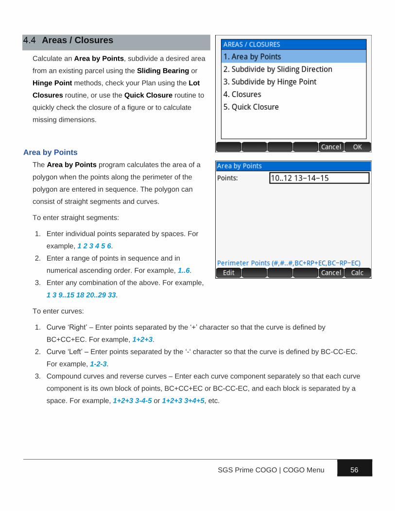
SGS Prime COGO | COGO Menu 56
Areas / Closures
Calculate an Area by Points, subdivide a desired area
from an existing parcel using the Sliding Bearing or
Hinge Point methods, check your Plan using the Lot
Closures routine, or use the Quick Closure routine to
quickly check the closure of a figure or to calculate
missing dimensions.
Area by Points
The Area by Points program calculates the area of a
polygon when the points along the perimeter of the
polygon are entered in sequence. The polygon can
consist of straight segments and curves.
To enter straight segments:
1. Enter individual points separated by spaces. For
example, 1 2 3 4 5 6.
2. Enter a range of points in sequence and in
numerical ascending order. For example, 1..6.
3. Enter any combination of the above. For example,
1 3 9..15 18 20..29 33.
To enter curves:
1. Curve ‘Right’ – Enter points separated by the ‘+’ character so that the curve is defined by
BC+CC+EC. For example, 1+2+3.
2. Curve ‘Left’ – Enter points separated by the ‘-‘ character so that the curve is defined by BC-CC-EC.
For example, 1-2-3.
3. Compound curves and reverse curves – Enter each curve component separately so that each curve
component is its own block of points, BC+CC+EC or BC-CC-EC, and each block is separated by a
space. For example, 1+2+3 3-4-5 or 1+2+3 3+4+5, etc.

SGS Prime COGO | COGO Menu 57
NOTE: An error occurs when the points provided as curve points do not actually define a curve, i.e. the
radius differs by more than the radius tolerance setting.
Any mix of straight segments and curves is accepted. For example, an area with straight segments and a
curve could be 10 11 12 13-14-15 which could also be entered as 10..12 13-14-15.
The area (square units and hectares/acres) and
perimeter are displayed following a valid input. The
program automatically determines the direction
(clockwise or counter clockwise) the points were
entered. The primary distance unit affects the results
displayed.
Export a DXF File of the area calculated
Exit the Area by Ponts program.
Return to the Input Form.
Sample Coordinates
Point,Northing,Easting,Elevation,Description
10,3000.0000,2000.0000,0.0000,AREA
11,2979.0430,2000.1800,0.0000,AREA
12,2976.3950,1995.4290,0.0000,AREA
13,2994.9938,1969.0919,0.0000,AREA
14,3007.1076,1951.9380,0.0000,AREA_CC
15,3004.0355,1972.7121,0.0000,AREA

SGS Prime COGO | COGO Menu 58
Subdivide by Sliding Direction
Calculate a specified area by sliding a line of fixed bearing. For
the diagram on the right, assume the known coordinates as
listed and the fixed bearing line to be 6°10’35” with a desired
area of 100m². The program will calculate the coordinates for
highlighted points 26 and 27 shown.
First, enter the points that define the fixed boundaries, in this
example those points are 22, 23 and 24.
Next, enter the directions from the first and from the last
point that you entered for the fixed points. Use any of
the standard directions input options.
Next, enter the desired area and the direction of the
sliding bearing.
The solution is displayed with the locations of the
solution points marked as “A” and “B” on the plot.
Export a DXF File of the area subdivided.
Exit the Area Subdivision program.
Return to the Input Form.
A prompt provides the option to store the solution
points.
Sample Coordinates
Point,Northing,Easting,Elevation,Description
21,2100.000,1100.000,0.000,SLIDE
22,2101.000,1090.000,0.000,SLIDE
23,2096.000,1086.000,0.000,SLIDE
24,2089.000,1089.000,0.000,SLIDE
25,2090.000,1099.000,0.000,SLIDE
25
22 21
23
24 27
26

SGS Prime COGO | COGO Menu 59
Subdivide by Hinge Point
Calculate a specified area by swinging a line from a hinge point
into another line of fixed bearing. For the diagram on the right,
assume the known coordinates as listed and the direction from
Point 35 to be parallel to the line 34-33 with a desired area of
180m². The program will calculate the coordinates for
highlighted point 36 shown.
First, enter the points that define the fixed boundaries,
starting with the hinge point. In this example those
points are 31, 32, 33, 34 and 35.
Next, enter the direction from the last fixed point
followed by the desired area. Use any of the standard
directions input options.
The solution is displayed with the location of the
solution point marked as “A” on the plot.
Export a DXF File of the area subdivided.
Exit the Area Subdivision program.
Return to the Input Form.
A prompt provides the option to store the solution point.
Sample Coordinates
Point,Northing,Easting,Elevation,Description
31,120.000,220.000,0.000,HINGE
32,130.000,220.000,0.000,HINGE
33,130.000,210.000,0.000,HINGE
34,111.000,203.000,0.000,HINGE
35,109.000,208.000,0.000,HINGE
33
36
35
32
31
34

SGS Prime COGO | COGO Menu 60
Closures
Closures are associated with the active project at the time of creation, and multiple closures can be
stored within each project.
Closure Manager
The Closure Manager keeps track of the closures computed in the current project.
Create a new Closure. The name and starting point coordinates are entered.
Delete the selected closure. A confirmation prompt is displayed.
Edit the name and starting point coordinates of the selected closure.
Load the selected closure for editing and calculating.
Closure Editor
When a closure is loaded, the segments that have been
defined are displayed.
Edit the selected segment.
Delete the selected segment. A confirmation
prompt is displayed.
Insert a segment above the selected segment.
Calculate the Closure.
Add a segment to the Closure. Line and Curve
segments can be added.

SGS Prime COGO | COGO Menu 61
Add Segment
When adding a segment, the input form features two pages. One page takes input to add a Line and the
other takes input to add a Curve. The input form continues in a loop until cancelled.
The Closure Editor displays the segments with their key
parameters once they are defined.
Delete Segment
Select a segment to delete and choose the menu
option. A confirmation is required.
Edit Segment
Select the segment to edit and choose the menu option.
The current information is loaded for editing.
Insert Segment
Select a segment and choose the menu option to insert a new segment before the selected segment.

SGS Prime COGO | COGO Menu 62
Closure Solution
When all the segments are defined, the Calculate option will display the results of the closure. The
Solution page shows the numeric results, while the Plot page will draw the segments.
Export Options
Export the closure results.
► Add Closure Report to Log File – Adds the
current closure results to a ClosureLOG.txt file.
With this option it is possible to have numerous
closures reported in a single TEXT file for
printing, etc.
► Clear Log File – Clears the ClosureLOG.txt file
if it exists.
► Export HTML Report – Creates an HTML
report of the closure. The user can enter a file
name for the report, which can then be viewed in a web browser on a PC or Mac.
► Export DXF File – Creates a DXF file of the closure lines and curves. The user can enter a file
name for the DXF file, which can then be viewed in a CAD program on a PC or Mac.
► Store Point Coordinates – Store the points that define the closure. Coordinates are calculated
from the starting point coordinates for the closure. The user can enter a Starting Point ID and a
descriptor for the points.
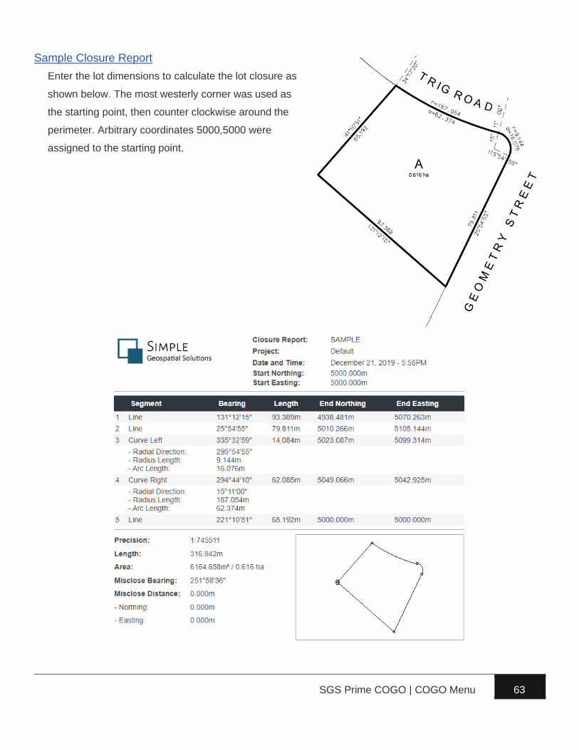
SGS Prime COGO | COGO Menu 63
Sample Closure Report
Enter the lot dimensions to calculate the lot closure as
shown below. The most westerly corner was used as
the starting point, then counter clockwise around the
perimeter. Arbitrary coordinates 5000,5000 were
assigned to the starting point.

SGS Prime COGO | COGO Menu 64
Quick Closure
A Quick Closure is created by entering the known dimensions of the sides of a figure. There are no points or
coordinates required and the results are not stored; it is optimized for quick entry and ease of use.
A closure may have one or two missing dimensions, which will be calculated whenever possible.
Curved segments may also be entered by specifying a chord distance and curve radius.
Examples will be used to illustrate the methods and results obtained.
Example 1 – Closure with all dimensions known
The Quick Closure routine immediately opens to an
input screen, prompting for the direction of the first
line.
The entered values of the previous input are
displayed for verification.
The menus provide the standard tools for working
with direction and distance inputs.
Enter each direction and distance as prompted, then after entering the fifth and final distance.

SGS Prime COGO | COGO Menu 65
The results are displayed when finished. The first page of the results shows the solution with figure
details and misclose information. A second page plots the figure geometry on the screen.
The menu:
Sets the solution page current.
Sets the adjusted solution page current.
Sets the plot page current.
Exit the Quick Closure routine and return
to the main menu.
Start a new closure.
NOTE: The adjusted solution is shown only when an
adjustment is possible. The adjusted length and area are
displayed.

SGS Prime COGO | COGO Menu 66
Example 2 – Closure with missing dimensions
Enter the dimensions of the first two lines, and the direction of the
third line. When prompted to enter the Distance 3 and 4 inputs;
simply leave them blank and press E.
The result in this case does not show a misclose. The calculated values of the missing dimensions are shown.

SGS Prime COGO | COGO Menu 67
Example 3 – Closure with curve
Enter the dimensions for the first three lines, and the
direction of the fourth line (chord). When prompted to
enter Distance 4, use the key on the menu to
specify that a chord distance is being entered.
After the chord distance is entered; a prompt will ask
for the radius of the curve. Enter a positive radius
value if the curve follows a clockwise direction and
enter a negative radius value if the curve follows a
counter clockwise direction. In this case it is a
clockwise direction, therefore a positive radius.
Enter the dimensions for the final line and then to finish.

SGS Prime COGO | COGO Menu 68
Fit Points
The Fit Points program consists of:
1. Best fit points to Straight Line, linear regression.
2. Best fit points to Circular Curve, like linear
regression but fits points to a circular curve.
3. Solve the position of a lost corner using the Double
Proportionate Method.
4. Solve the position of a lost corner using the
Irregular Boundary Adjustment Method.
5. Solve the positions of lost angle points using the
Grant Boundary Adjustment Method.
Fit to Straight Line
Enter a series of points to compute the least squares
straight line that best fits the points. Enter point
numbers using any of the point numbers input options.
An un-weighted linear regression method that
minimizes X and Y residuals simultaneously is used to
calculate the line.
The direction and Y-Intercept of the line, the correlation
coefficient (a value between -1 and 1), and the point
offsets standard deviation are computed and displayed.

SGS Prime COGO | COGO Menu 69
The Menu
Displays the solution details.
Displays the perpendicular offsets to the line
for each point used in the computation.
Option to enter a direction constraint for the
line or use the best fit direction. The solution details
page indicates whether a Best Direction or Fixed
Direction is in effect.
While viewing the perpendicular
offsets, toggle whether the selected point will be used
for the calculation.
Proceeding with the adjustment provides the option to overwrite the existing points or to create new
points.
Points are shifted perpendicular to the best-fit line to minimize the shift.
Sample Coordinates
Point,Northing,Easting,Elevation,Description
70,5142.364,3951.682,0.000,FIT_LINE
71,5126.301,4010.781,0.000,FIT_LINE
72,5122.959,4022.875,0.000,FIT_LINE
73,5119.064,4037.366,0.000,FIT_LINE
74,5109.751,4071.672,0.000,FIT_LINE
75,5105.428,4087.524,0.000,FIT_LINE

SGS Prime COGO | COGO Menu 70
Fit to Circular Curve
The main purpose of this program is to calculate the radius and
the coordinates of the radius point of the least squares circle
that best fits a series of points. When providing points along one
or both tangents, the program will also solve the BC and/or EC
point coordinates.
In the input form, enter a series of points along the
curve to compute the circle that best fits the points.
Enter point numbers using any of the point numbers
input options.
Optional: Also enter points on the Tangent In/Out to
compute the BC/EC points. If specifying tangent points,
it is important to select the correct curve direction
Right/Left.
The curve solution displays the computed radius, the
radius standard deviation, the coordinates of the radius
point, and if applicable, the bearings of the back and
forward tangents.
Point on back
tangent
Curve Points
Point on forward tangent
46
45 44
43 42 41

SGS Prime COGO | COGO Menu 71
The Menu
Displays the solution details.
Displays the radial offsets to the curve for
each point used in the computation.
Option to enter a radius constraint for the
curve or use the best fit radius. The solution details
indicate whether a Best Radius or Fixed Radius is in
effect.
While viewing the radial offsets,
toggle whether the selected point will be used for the
calculation.
Proceeding with the adjustment provides the option to overwrite the existing points or to create new
points.
Prompts will be displayed to choose whether to store the Origin Point, and if possible; the BC and EC
points.
Points are shifted radially to the best-fit curve to minimize the shift.
Sample Coordinates
Point,Northing,Easting,Elevation,Description
41,7444.140,5354.860,0.000,FIT_CURVE
42,6947.930,6975.820,0.000,FIT_CURVE
43,6572.600,7577.110,0.000,FIT_CURVE
44,6071.290,8084.030,0.000,FIT_CURVE
45,5542.000,8431.380,0.000,FIT_CURVE
46,4268.900,8877.960,0.000,FIT_CURVE

SGS Prime COGO | COGO Menu 72
Double Proportion
“The term ‘double proportionate measurement’ is applied to a new measurement made between four
known corners, two each on intersecting meridional and latitudinal lines, for the purpose of relating the
cardinal equivalent intersection to both.” (Page 166, BLM Manual of Surveying Instructions 2009).
The Double Proportion program solves this type of
problem by accepting point numbers for the four known
corners, and the record measurements to the lost
corner.
The first input form requires existing point numbers of
the corners to the north, east, south and west of the lost
corner.
The second input form requires the record bearings and
distances to the known corners west and east of the lost
corner.

SGS Prime COGO | COGO Menu 73
The third input form requires the record bearings and
distances to the known corners north and south of the
lost corner.
The solution displays the coordinates of the calculated
corner point, and the dimensions to the four known
corners.
The option to store the calculated corner point is
provided upon completion.
Sample Coordinates
Point,Northing,Easting,Elevation,Description
80,18000.000,13000.000,0.000,DP_NORTH
81,12686.799,16151.626,0.000,DP_EAST
82,10047.468,13460.294,0.000,DP_SOUTH
83,12714.524,10834.089,0.000,DP_WEST

SGS Prime COGO | COGO Menu 74
Irregular Boundary Adjustment
Irregular boundaries are the result of boundaries
surveyed from opposite directions, or piecemeal
surveys where resulting boundaries are not straight
lines. “In order to restore one or more lost corners or
angle points on such irregular exterior, a retracement
between the nearest known corners is made on the
record courses and distances to ascertain the direction
and length of the closing distance. A position is
calculated for each lost corner or angle point at the
record position.” (Page 174, BLM Manual of Surveying
Instructions 2009) A combination of single proportion and compass rule is then used to re-establish the
lost corner. The direction (East-West or North-South) determines how the adjustment is performed.
The Irregular Boundary program prompts for the
direction of the line, and then the first input form
requires the point numbers for the surveyed points (W +
E, or N + S).
The second input form requires the record dimensions
to the corners on either side of the lost corner.

SGS Prime COGO | COGO Menu 75
The solution displays the coordinates of the calculated
corner point, and the dimensions to the two known
corners.
The option to store the calculated corner point is
provided upon completion.
Sample Coordinates
Point,Northing,Easting,Elevation,Description
85,11000.000,18000.000,0.000,IB_SOUTH
86,16202.385,18075.912,0.000,IB_NORTH

SGS Prime COGO | COGO Menu 76
Grant Boundary Adjustment
“In many of the States there are irregular grant and reservation boundaries that were established prior to
the public rectangular surveys. In these cases, the township and section lines are regarded as the
closing lines. The grant boundary field notes may call for natural objects, but these are often
supplemented by metes-and-bounds descriptions. The natural calls are ordinarily given precedence then
the existent angle points of the metes-and-bounds survey. The lost angle points are then restored by
uniformly orienting the record courses to the left or right and adjusting the lengths of the lines on a
constant ration.” (Page 176, BLM Manual of Surveying Instructions 2009)
The Grant Boundary program requires a series of
points that define the grant boundary, starting with a
known (found) point followed by calculated points using
record dimensions. The first field asks for these points.
The second field asks for a Closing Point, which is a
found original point representing the last calculated
point that was entered. The spatial difference between
the closing point and the last calculated point
determines the adjustment parameters.
The calculated rotation and scale are displayed on the
results screen.
A choice is presented to adjust the record points.
Proceeding with the adjustment provides the option to
overwrite the existing points or to create new points.
Sample Coordinates
Point,Northing,Easting,Elevation,Descript
90,15000.0000,11000.0000,0.0000,GRANT
91,15008.3755,10990.0184,0.0000,GRANT
92,15027.8573,10960.0192,0.0000,GRANT
93,15136.4522,10883.9802,0.0000,GRANT
94,15136.4522,10776.6602,0.0000,GRANT
95,15126.4853,10744.0597,0.0000,GRANT
96,15123.7945,10667.0067,0.0000,GRANT
97,15123.7945,10638.7067,0.0000,GRANT
98,15084.8497,10558.8578,0.0000,GRANT
99,15103.3462,10518.4399,0.0000,GRANT

SGS Prime COGO | Adjust Menu 77
► Compass Rule – Perform a compass rule
adjustment on a Closed Figure or Close to
Known Point traverse.
► Rotate / Mirror – Rotate around Base Point,
Rotate around Origin (0,0) and Mirror along
Baseline.
► Shift / Average – Shift by ΔX/ΔY/Δ, Shift by
Distance/Direction/ΔZ, Shift by From/To Points and Average Points.
► Scale Points – Scale from Base Point, and Scale from Origin (0,0,0).
► Transform Coordinates – Helmert Transformation and 3D to Plan Cross Section.
Compass Rule
A “compass rule” or “bowditch rule” adjustment distributes the linear misclose of a traverse proportionally
throughout each leg of a traverse. A ‘closed figure’ traverse ends back on the starting point while a ‘close to
fixed point’ traverse ends on a known control point that is held fixed.
Closed Figure
A known starting point, followed by a series of intermediate
points, and ending back on the starting point defines a closed
figure. Prior to adjustment, the loop ending point coordinates
as measured will differ from the starting point coordinates. The
difference between these coordinates will be distributed
proportionally through each leg of the figure.
50
52
53
54
55
(56)
51

SGS Prime COGO | Adjust Menu 78
First, enter the point numbers using any of the point
numbers input options, and select the Adjustment Type.
Next, an option to Balance Angles is presented. If the
closing angle is known, choose “Yes”, otherwise choose
“No”.
If the user selected “Yes” to balance angles, an input
form will allow for the closing angle to be entered.
The COMPASS RULE RESULTS screen displays
information about the adjustment including the angle
balance information, precision, the perimeter of the
figure, and the misclose information.
Display the Adjustment Solution.
Display the unadjusted and adjusted distances
for each course of the traverse.
Display the unadjusted and adjusted
directions for each course of the traverse.
Proceed with adjusting the points.

SGS Prime COGO | Adjust Menu 79
Examples of the distance and direction result pages:
Proceeding with the adjustment will present the option
to Renumber or Overwrite the existing point numbers.
When renumbering, a description for the new points can
also be set.
Sample Coordinates
Point,Northing,Easting,Elevation,Descript
50,6102.894,4125.949,0.000,CRA_CLOSED
51,6120.510,4191.528,0.000,CRA_CLOSED
52,6096.092,4283.143,0.000,CRA_CLOSED
53,6023.426,4256.416,0.000,CRA_CLOSED
54,6056.123,4166.749,0.000,CRA_CLOSED
55,5995.827,4158.356,0.000,CRA_CLOSED
56,6102.885,4125.942,0.000,CRA_CLOSED
Close to Fixed Point
A close to fixed point traverse begins on a known control point
followed by a series of intermediate points and ends on a
second known control point which will be held fixed. The
difference between the measured ending point coordinates
and the fixed values will be distributed proportionally through
each leg of the traverse.
60
61
62
63 (69)
64

SGS Prime COGO | Adjust Menu 80
First, enter the point numbers using any of the point numbers input options, and select the Adjustment
Type. When a ‘Close to Fixed Point’ type is selected, the following input form will ask for the Fixed Point.
The COMPASS RULE RESULTS screen displays
information about the adjustment including the
precision, the length of the figure, and the misclose
information.
Display the Adjustment Solution.
Display the unadjusted and adjusted distances
for each course of the traverse.
Display the unadjusted and adjusted
directions for each course of the traverse.
Proceed with adjusting the points.
Sample Coordinates
Point,Northing,Easting,Elevation,Descript
60,7033.458,5311.207,0.000,CRA_KNOWN
61,7070.237,5360.793,0.000,CRA_KNOWN
62,7037.104,5460.587,0.000,CRA_KNOWN
63,7010.119,5550.529,0.000,CRA_KNOWN
64,7028.068,5612.263,0.000,CRA_KNOWN
69,7028.060,5612.266,0.000,CRA_KNOWN

SGS Prime COGO | Adjust Menu 81
Rotate/Mirror Points
Rotate Points around a base point or the coordinate
system origin, and Mirror Points mirrors points along a
baseline.
Rotate around Base Point
First, enter the point number to use as a base point.
Next, select if you’re entering a known rotation angle, or
if you are calculating the rotation angle from two
reference directions.
► Enter a positive angle for clockwise rotation and
a negative angle for a counter clockwise
rotation.
► Use any of the standard directions input options
to enter reference directions.
Next, enter the points to rotate, and select how to store the newly calculated points.

SGS Prime COGO | Adjust Menu 82
Rotate around Origin (0,0)
Like Rotate Around Base Point, except no base point is required, the points will be rotated around 0,0.
Mirror along Baseline
First, enter two points to define a baseline.
Next, enter the points to mirror and specify how to store the new coordinates.

SGS Prime COGO | Adjust Menu 83
Shift/Average Points
Point coordinates can be shifted by using one of three
possible methods, and a range of point coordinates can
be averaged to create a new point at the calculated
average position. The 3D to Plan option transforms 3D
measurements to 2D plan cross sections.
Shift by ΔX/ΔY/ΔZ
Enter the changes in Northing, Easting and Elevation to define the shift parameters.
Next, enter the points to shift, and select how to store the newly calculated points.

SGS Prime COGO | Adjust Menu 84
Shift by Distance/Direction/ΔZ
Enter the horizontal Distance, the Bearing and the change in Elevation to define the shift parameters.
Use any of the standard distances and directions input options.
Next, enter the points to shift, and select how to store the newly calculated points.
Shift by From/To Points
Enter the From Point and To Point to allow the program to calculate the 3D shift parameters between
the two points.
Next, enter the points to shift, and select how to store the newly calculated points.

SGS Prime COGO | Adjust Menu 85
Average Points
Enter a series of points to compute their arithmetic
mean coordinate values. Point numbers can be entered
using any of the point numbers input options. At
minimum two points are required to calculate average
values.
The solution displays the calculated coordinates, their
standard deviation and the range in coordinate values.
The user is given the option to store the averaged point
in the project database.

SGS Prime COGO | Adjust Menu 86
Scale Points
Scale Points from a Base Point or from the coordinate
system origin (0,0).
Scale from Base Point
Point coordinates can be scaled from a base point with
separate scale factors for the horizontal and vertical
components.
First, enter the point number to use as the Base Point.
Next, specify the horizontal and vertical scale factors.
Options exist on how to define the scale factors:
► User Entered – Enter a scale factor value. It is possible to enter a math operation such as
1/0.99962051 to calculate the scale factors.
► Feet to Meters – The scale factor is automatically determined.
► Meters to Feet – The scale factor is automatically determined.
► Input Scale Factor – From User Settings.
► Output Scale Factor – From User Settings.
► Computed – From existing and new reference distances, horizontal scale factor only.
Last, enter the points to scale, and select how to store the newly calculated points.
Scale from Origin (0,0,0)
Like Scale from Base Point, except no base point is required, the points will be scaled from 0,0,0.

SGS Prime COGO | Adjust Menu 87
Transform Coordinates
Transform point coordinates in one coordinate system
to another by matching up control points using the
Helmert Transformation tool or create 2D cross
section points from points on a 3D feature such as a
building face using the 3D to Plan Cross Section
utility.
Helmert Transformation
The Helmert Transformation program is a least squares coordinate transformation program that allows
the user to transform points from one coordinate system to another. A two-dimensional conformal
coordinate transformation (aka four-parameter similarity transformation) is used to calculate the least
squares transformation. Scale, rotation and translation are computed when a minimum of two common
control points are present in two separate coordinate systems. The procedure in general is:
1. Match up control points from both coordinate systems, i.e. these points represent the same objects
in two different coordinate systems.
2. Calculate the transformation and review the residuals for each control pair that was defined.
3. If necessary, modify the control points used to address any “poorly fitting” control pairs.
4. Apply the transformation to a specified range of points.
The main Helmert Transformation screen accepts all
input through the menu:
Add control pairs to be used for the
calculation.
Delete the selected control pair from the
calculation.
Edit the selected control pair.
Set the Scale Parameter, which can be fixed
at 1 or calculated best fit. The title in the header
indicates (No Scale) when the scale parameter is fixed, or (Scaled) when the calculated scale factor will
be applied.
Once at least two pairs are added, their horizontal distance residuals are displayed.

SGS Prime COGO | Adjust Menu 88
Add Control Pairs
The Local Point is in the coordinate system that you
wish to transform, while the Fixed Point is in the
coordinate system that is not changing. Points can be
matched in 1D, 2D, 3D or None. You may continue
entering all your control pairs without leaving the
DEFINE CONTROL PAIRS input form.
Delete or Edit Control Pairs
Control pairs can be deleted or edited when necessary.
From the main Helmert Transformation screen, select
a control pair and use menu options to delete or edit the
selected control points. The screen updates
immediately to reflect the changes made.
Calculate Solution
Use to display the calculated transformation parameters based on the defined control pairs.
The solution presented displays the best-fit
transformation parameters (scale, rotation, and
translation in northing and easting) as well as the
standard deviation in the northing and easting and the
calculated average elevation shift between any/all
control pairs that were matched 3D. The menu:
Display the transformation solution.
Display the coordinate residuals for each
control pair.
Display the polar distance and direction residuals for each control pair.
Return to the previous input screen to Add/Delete/Edit control pairs.

SGS Prime COGO | Adjust Menu 89
Examples of the residual screens:
Apply Transformation
Use when ready to apply the transformation.
Enter the points to transform and select how to store the
newly calculated points.
Sample Coordinates
Point,Northing,Easting,Elevation,Description
201,5366358.241,470146.326,22.112,HT_LOCAL
202,5366207.625,470340.584,17.416,HT_LOCAL
203,5366043.182,470551.834,14.643,HT_LOCAL
204,5366215.676,470348.232,0.000,HT_LOCAL
205,5366290.117,470401.822,0.000,HT_LOCAL
206,5366123.497,470616.424,0.000,HT_LOCAL
207,5366048.800,470552.152,0.000,HT_LOCAL
1201,5366557.381,470050.977,22.107,HT_FIXED
1202,5366406.762,470245.234,17.411,HT_FIXED
1203,5366242.317,470456.485,14.639,HT_FIXED

SGS Prime COGO | Adjust Menu 90
3D to Plan Cross Section
In the diagram on the right, consider the red dots shown as being
reflector-less measurements made with a total station. The goal
is to calculate the ratio of glass surface area to total surface area
of the wall. The 3D to Plan program transforms the 3D measured
coordinates into 2D plan points to create a section view.
First, define the section cut line by entering a point towards the
left of the section cut line, and a point to the right of the section
cut line. Consider the points measured at the base of the walls as the section cut line, Point 101 on the
left and Point 102 on the right. Elevations of the calculated points can be calculated from their offsets
relative to the baseline, or the elevations can be set to zero, if not important.
Next, enter the points to transform, and select how to store the newly calculated points.
Sample Coordinates
101,5000.000,5000.000,68.743,3D2PLAN
102,4982.603,5019.322,68.743,3D2PLAN
103,5000.000,5000.000,77.743,3D2PLAN
104,4982.603,5019.322,76.743,3D2PLAN
105,4997.323,5002.973,71.743,3D2PLAN
106,4994.647,5005.945,71.743,3D2PLAN
107,4997.323,5002.973,75.743,3D2PLAN
108,4994.647,5005.945,75.743,3D2PLAN
109,4987.956,5013.377,71.743,3D2PLAN
110,4985.279,5016.349,71.743,3D2PLAN
111,4987.956,5013.377,75.743,3D2PLAN
112,4985.279,5016.349,75.743,3D2PLAN
113,4999.852,4997.175,78.243,3D2PLAN
114,4979.778,5019.470,78.243,3D2PLAN
115,4989.815,5008.323,84.493,3D2PLAN
101
102

SGS Prime COGO | Tools Menu 91
► Triangle Solver – Solve a plane triangle from three
known values.
► Horizontal Curves –Features a Circular Curve
Solver, Curve Through Fixed Point Solver, and a
Spiral Curve Solver.
► Vertical Curves – Various methods including
Grades and Length known, Elevations and
Length known, Fixed Point, VPI and Grades known, Fixed Point, BVC and Grades known and
Intersect Slopes from two known points.
► RPN Calculator – Calculator app designed for survey calculations.
► Configure Settings – Configure User Settings.
Triangle Solver
The triangle solver accepts three known values (at least
one of which must be a side) and solves for the
remaining values.
For side value inputs, any of the standard distances
input options are accepted to allow the user to inverse
points in the current job database to calculate distances
for triangle sides, as well as any of the other operations.
The output screen displays the solved values, including
the triangle area and perimeter.

SGS Prime COGO | Tools Menu 92
Horizontal Curves
Three options to solve horizontal curves:
1. Circular Curve Solver – Solve a simple circular
curve by entering two known elements.
2. Curve Through Fixed Point – Calculate the curve
that passes through a fixed point. Calculations are
possible when a point on the back tangent, at the
PI, on the forward tangent, and the fixed point are
provided.
3. Spiral Curve Solver – Solves all the Spiral-Curve-
Spiral parameters when entering a Spiral Length, a
total SCS deflection angle, and the curve radius.
Circular Curve Solver
The circular curve solver requires two known curve
elements and solves for the rest. Acceptable input
combinations include:
► The radius and any of the other accepted inputs.
► The deflection angle and any of the other accepted
inputs.
► The arc length and the chord length. NOTE: THIS
TYPE OF SOLUTION INVOKES THE ITERATIVE NEWTON’S
METHOD TO SOLVE FOR THE REMAINING VALUES. THE
RESULT ACCURACY DEPENDS ON THE INPUT
PRECISION.
Degree of Curve
A Deg of Curve button provides easy access to determine the radius of the curve by degree of curve,
both chord and arc definitions are available.

SGS Prime COGO | Tools Menu 93
The solution displays all the elements of the circular
curve, including the sector, segment and fillet areas.
The button on the menu features Tangent
Offset calculations.
Curve Calculations
Further calculations are possible with the solved curve
parameters.
► Tangent Offset by Station – Enter any station
on the curve to calculate the tangent distance
and offset to layout the curve using the Tangent
Offset method.
► Tangent Offsets by Interval – Calculates the
tangent distances and offsets for all stations on
the curve at a specified interval.
► Sub-Chord by Station – Enter any station on
the curve to calculate the turned angle and
chord distance from either end of curve to layout
the curve using the Sub-Chord method.
► Sub-Chords by Interval – Calculates the turned
angles and chord distances for all stations on
the curve at the specified interval.
For all methods, enter the known station at either the
BC, PI or EC to continue with the calculations.

SGS Prime COGO | Tools Menu 94
Tangent Offset by Station
Enter any station on the curve, enter an offset from centerline (optional), choose the curve direction, and
choose the Calculation Reference (Shortest tangent distance, From BC, or From EC) to calculate and
display the tangent distance and tangent offset.
Tangent Offset by Intervals
Enter the station interval, enter an offset from centerline (optional), choose the curve direction, and choose the
Calculation Reference (Shortest tangent distance, From BC, or From EC) to calculate and display the tangent
distances and tangent offsets for all stations at the given interval.

SGS Prime COGO | Tools Menu 95
Sub-Chord by Station
Enter any station on the curve, enter an offset from centerline (optional), choose the curve direction, and
choose the Calculation Reference (Shortest chord distance, From BC, or From EC) to calculate and
display the chord distance and turned angle.
Sub-Chords by Intervals
Enter the station interval, enter an offset from centerline (optional), choose the curve direction, and choose the
Calculation Reference (Shortest chord distance, From BC, or From EC) to calculate and display the chord
distances and turned angles for all stations at the given interval.

SGS Prime COGO | Tools Menu 96
Curve Through Fixed Point
The Curve through Fixed Point solver solves a
curve that is required to fit fixed tangents and a
fixed point. In the diagram to the right, let’s
assume that the back tangent from Point 1 to
Point 2 is a street curb line, and the forward
tangent from Point 2 to Point 3 is also a street
curb line. A curve is required so that the curb will
pass through Point 4, which represents the back
of a catch basin, for example.
In the input form; enter the points on the BT (Back
Tangent), at the PI (Point of Intersection), on the FT
(Forward Tangent), and OC (On the Curve).
The diagram is for general reference only.
Sample Coordinates
Point,Northing,Easting
1,4684.500,3249,912
2,4683.400,3299.900
3,4635.620,3314.635
4,4674.714,3299.210

SGS Prime COGO | Tools Menu 97
The solution displays the curve parameters, and the
updated diagram shows the direction of the solved
curve by placing the BC & EC labels at the appropriate
locations.
After reviewing the solution, the options to store the
calculated Radius Point, the calculated BC Point, and
the calculated EC Point will be presented.
Spiral Curve Solver
Solve all parameters of an equal spiral transition curve.
Input the Spiral Length, Total Deflection Angle, and
Curve Radius to solve the rest. The Curve Radius can
also be solved by using the Deg of Curve button.
The solution is displayed on two pages, toggle the page
by using the menu.
See the next page for a diagram of the spiral geometry.

SGS Prime COGO | Tools Menu 98
Reference Diagram
The diagram below illustrates the spiral geometry and associated symbols.
Below is a table legend of the spiral parameter symbols.
Ts Tangent of Spiral-Curve-Spiral Cs Long Chord (Spiral)
X Distance along Tangent from TS to Point at Right Angle to SC
Cc Curve Chord (not labelled)
Y Right Angle distance from Tangent to SC Δs Spiral Delta
Tlng Long Tangent (Spiral) Δc Curve Delta
Tsho Short Tangent (Spiral) Δ Total Delta
Ls Length of Spiral (not labelled) A Spiral Parameter
q Distance along Tangent to a Point at Right Angle to Ghost BC
R Curve Radius
p Distance from Tangent that the Curve (Ghost BC) has been Offset
Lc Length of Curve (not labelled)
Tc Tangent of Curve (not labelled)

SGS Prime COGO | Tools Menu 99
Vertical Curves
The Vertical Curve Solver solves vertical curves using
various combinations of known parameters, including:
1. Grades and Length known – Requires a known
station at the BVC, VPI or EVC, the vertical curve
length, entry and exit grades, and a known
elevation at the BVC VPI, EVC or the High/Low
point on the curve.
2. Elevations and Length known – Requires a known
station at the BVC, VPI or EVC, the vertical curve length, and elevations at the BVC, VPI and EVC.
3. Fixed Point, VPI and Grades known – Requires the station and elevation at the VPI, a fixed-point
station and elevation, entry and exit grades.
4. Fixed Point, BVC and Grades known – Requires the station and elevation at the BVC, a fixed-point
station and elevation, entry and exit grades.
5. Intersect Slopes from two known points – Requires the vertical curve length, the entry grade, a
station with a known elevation on the entry tangent, the exit grade, and a station with a known
elevation on the exit tangent.
NOTE: BVC = Beginning of Vertical Curve, VPI = Vertical Point of Intersection, and EVC = End of
Vertical Curve.
The diagram below illustrates the vertical curve geometry.
VPI
BVC
EVC
Curve Length
Exit Tangent
Entry Tangent

SGS Prime COGO | Tools Menu 100
Grades and Length known
Enter all the required information to solve the curve.
► Choose the point on the vertical curve with a
known station (BVC, VPI or EVC)
► Enter the known station for the point
► Choose the point on the vertical curve with a
known elevation (BVC, VPI, EVC or the
High/Low Point)
► Enter the known elevation for the point
► Enter the vertical curve length
► Enter the entry grade
► Enter the exit grade
The solution displays the stations and elevations for
each the BVC, VPI, EVC and High/Low Point. See the
Solution Screen and Calculations section for more
information.
0+000.000
Elev=235.500m
100.000m

SGS Prime COGO | Tools Menu 101
Elevations and Length known
Enter all the required information to solve the curve.
► Choose the point on the vertical curve with a
known station (BVC, VPI or EVC)
► Enter the known station for the point
► Enter the vertical curve length
► Enter the BVC elevation
► Enter the VPI elevation
► Enter the EVC elevation
The solution displays the stations and elevations for
each the BVC, VPI, EVC and High/Low Point. See the
Solution Screen and Calculations section for more
information.
0+000.000
Elev=235.500m
100.000m
Elev=239.550m
Elev=238.750m

SGS Prime COGO | Tools Menu 102
Fixed Point, VPI and Grades known
Enter all the required information to solve the curve.
► Enter the VPI station
► Enter the VPI elevation
► Enter the fixed station
► Enter the elevation at the fixed station
► Enter the entry grade
► Enter the exit grade
The solution displays the stations and elevations for
each the BVC, VPI, EVC and High/Low Point. See the
Solution Screen and Calculations section for more
information.
0+050.000
0+020.000 Elev=238.222m
Elev=235.500m

SGS Prime COGO | Tools Menu 103
Fixed Point, BVC and Grades known
Enter all the required information to solve the curve.
► Enter the BVC station
► Enter the BVC elevation
► Enter the fixed station
► Enter the elevation at the fixed station
► Enter the entry grade
► Enter the exit grade
The solution displays the stations and elevations for
each the BVC, VPI, EVC and High/Low Point. See the
Solution Screen and Calculations section for more
information.
0+000.000
0+020.000 Elev=238.222m
Elev=239.550m

SGS Prime COGO | Tools Menu 104
Intersect Slopes from two known points
Enter all the required information to solve the curve.
► Enter the curve length
► Enter the entry grade
► Enter a known station on the entry tangent
► Enter the elevation at the known station
► Enter the exit grade
► Enter a known station on the exit tangent
► Enter the elevation at the known station
The solution displays the stations and elevations for
each the BVC, VPI, EVC and High/Low Point. See the
Solution Screen and Calculations section for more
information.
0+010.000 Elev=238.740m
0+106.000 Elev=239.140m

SGS Prime COGO | Tools Menu 105
Solution Screen and Calculations
For each of the combinations of known parameters to
solve a vertical curve; the solution screen displays the
unknown solved parameters, and the menu on the
solution screen is the same for all combinations,
offering the same functionalities:
Calculate elevations at all stations at a given
interval.
Calculate elevations on the vertical curve by
entering a station.
Calculate stations on the vertical curve by entering an elevation.
Calculate Intervals
Enter a station interval to solve the elevations and instantaneous grade for each station at the given
interval. The BVC and EVC elevations are always solved, regardless of their station. Scroll down to see
all the results if they do not fit on one screen.

SGS Prime COGO | Tools Menu 106
Calculate Elevations
Enter any station to solve its elevation on the vertical curve.
When entering a station lower than the BVC station or greater than the EVC station, a notation will
indicate such a case.
Calculate Stations
Enter an elevation to solve the station(s) on the vertical curve. Both solutions are displayed when two
solutions exist. Only stations between the BVC and EVC are solved.

SGS Prime COGO | Tools Menu 107
RPN Calculator
The RPN Calculator is designed for survey calculations with units for distance, angle, area and volume.
Main Interface
Use the touch screen to:
► Select an object on the stack
► Open the Edit Line
► Toggle the current menu
► Execute a menu option
The Keyboard keys have common functions assigned:
► E to DUP Level 1 of the stack
► L or R to SWAP Level 1 and 2 of the stack. Moves the cursor when the Edit Line is open.
► \ to DROP Level 1 of the stack. S + \ clears the stack.
► & to exit the application, cancel the Edit Line, or unselect a stack object.
► U or D to scroll through the stack. S + U or D jumps to the top or bottom level of the
stack. When no object is selected on the stack, D opens the Edit Line.
► S and + to UNDO the previous action. Only one level of UNDO is possible.
► a / b / S + c to toggle the Vars / Tools / Units menus.
► S + p to store a variable, more details in the Vars menu section.

SGS Prime COGO | Tools Menu 108
Stack Area
The Stack Area displays six levels of the stack. Stack objects can be selected by using the touch screen
or the U and D keys. The stack will scroll up and down as required.
When a stack object is selected, the menu will always change to the following options:
Edit the selected value. When editing is
complete, the value remains selected.
Strip any associated unit from the object.
Copy the object to the Clipboard.
Echoes the selected object to the Edit Line.
When editing is complete, the previous stack selection
is no longer selected.
Pick the selected object and copy it to Level 1
of the stack. The object remains selected on the stack.
Roll the selected object down to Level 1 of the stack. The stack level of the selection is not
changed.
Edit Line
The Edit Line displays the value being entered or edited and is also used to display any status or error
messages. When the Edit Line is open; the menu updates with the current angle unit and both primary
and secondary distance units to assign to the entered value, also , and . Copy
and Paste are available with S and V, and S and M. The option takes input
ranging from -1 to 11 to set display mode to Fixed (0 to 11) or Standard (-1).
NOTE: It is possible to inverse the distance between points in the database with the format From..To.
NOTE: It is possible to enter feet, inches, fractions in the specified comma-delimited format. The current
distance unit will automatically be applied to the value entered. The unit conversion happens
automatically if required.
Menu Toggles
Four different menus are available within the app for specific tasks; the menu toggles change the current
menu or group of menus.

SGS Prime COGO | Tools Menu 109
Menus
Vars Menu
The Vars Menu displays all the variables stored on the HP Prime as HVars. The first and last menu keys
are used to change the page of the menu while the middle four keys show the names of the variables.
► Tap any of the keys to pop the variable’s content onto Level 1 of the stack.
► Press S and then tap any of the keys to store the value on Level 1 of the stack into the
variable.
► Enable A mode and then 0 followed by the menu key to quote a variable name. Use the
option from the Tools menu to purge the quoted variable.
► Press S + p to store a variable. If Level 1 is a string then it will be used as the variable
name to store object on Level 2, otherwise prompts for a variable name to store Level 1.
► Type the variable name (without quotes) followed by E to recall the variable contents.
► When storing or recalling a variable, any associated units are kept intact (with the exception of
the Links distance unit).
Tools Menu
Edit Level 1 of the stack.
Strip any associated unit from the object on Level 1 of the stack.
Stores the object on Level 2 of the stack into the variable name on Level 1 of the stack. When
Level 1 is not a string, then a touchscreen keypad opens to enter a variable name.
Purges the variable name on Level 1 of the stack from memory. When Level 1 is not a string,
then a list of variables is shown, and the variable can be chosen to be purged.
Toggles between rectangular and polar display modes of vectors.
Requires a vector on Level 1 of the stack.
Compiles a vector from stack objects or explodes a vector if Level 1 contains a vector.
To build a vector; Level 1 of the stack needs to be a 2 or 3 to specify the dimension (2D or 3D) and levels
above must contain either the rectangular or polar components of the vector.
Exploding a vector results in vector components on the stack and a 2 or 3 on Level 1 of the stack
indicating if it was a 2D or 3D vector.

SGS Prime COGO | Tools Menu 110
Units Menu
Four pages of the Units menu exist. The first and last menu keys on each page are used to change the
page of the menu. The four menus are
► Angle Units
► Distance Units
► Area Units
► Volume Units
Units can be assigned to any value as it is typed, is on Level 1 of the stack or is selected on the stack.
Unit conversions are single tap if the existing value is unit-less or is of the same type of unit.
Stack Menu
DUPlicate Level 1 of the stack. {… 3 2 1} to {… 3 2 1 1}
SWAP Level 1 and Level 2 of the stack. {… 3 2 1} to {… 3 1 2}
DROP Level 1 of the stack. {… 3 2 1} to {… 3 2}
Copy OVER Level 2 and place it on Level 1 of the stack. {… 3 2 1} to {… 3 2 1 2}
ROTate the bottom three levels of the stack. {… 3 2 1} to {… 2 1 3}
UNROTate the bottom three levels of the stack. {… 3 2 1} to {… 1 3 2}
Vector objects
2D and 3D vectors are supported.
► Use S + 5 to open the vector entry form where a rectangular or polar vector can be
entered.
► Use S + * to convert the vector on Level 1 of the stack between polar and rectangular
display modes.
► Vectors can be added or subtracted, and multiplied or divided by a scalar.
Configure Settings
See the User Settings chapter.

SGS Prime COGO | Points Menu 111
► Store and Edit Points – Store new points in the
current project database or edit the coordinates and
description of an existing point.
► Delete Points – Delete points from the current
project database.
► Renumber Points – Renumber a range of points
using a New Starting Number scheme or an
Additive Number scheme.
► Plot Points – Graphically display the points in the current project. Zoom and pan functionality is
available with all points in the current project, or a specified range of points.
► Import / Export – Import ASCII Points, Export ASCII Points and Export DXF Points.
Store and Edit Points
It is possible to store and edit points in the same input
form.
Point ID
Enter a Point ID to edit its coordinates or to store a new
point. The coordinate and description fields
automatically populate with existing coordinates and
description if the point exists.
Options while editing this field:
Search for the lowest unused point number in the job.
Search for the lowest unused point number starting from the current value.

SGS Prime COGO | Points Menu 112
Delete Points
Delete individual points, a range of points or all the
points from the current job. To delete individual points
or ranges of points, enter points using any of the point
numbers input options.
Check the All Points checkbox to delete all points.

SGS Prime COGO | Points Menu 113
Renumber Points
Two methods are available for point renumbering.
Neither method overwrites conflicting point numbers.
By Starting Number
Enter the New Starting Point ID to use for renumbering.
The points’ new numbers will begin at this starting
number, or in the case where the provided starting
number exists, the next available number.
Enter the points to be renumbered using any of the
point numbers input options or check the All Points
checkbox to renumber all the points in the current
project.
Some examples to illustrate this method of renumbering
points:
1. When a new starting point number is given as 101, and existing points 1 to 4 are to be renumbered,
Point 1 becomes 101, 2 becomes 102, etc.
2. Same as above but in fact there already exists a Point 101, then Point 1 becomes 102, 2 becomes
103, etc.
3. Same as above but there is no Point 3, then 1 becomes 101, 2 becomes 102, and 4 becomes 103.

SGS Prime COGO | Points Menu 114
By Additive Number
Enter an additive number to add to existing point
numbers as a renumbering method. In the case where
this added number creates a point number that already
exists, the next available number will be used.
Enter the points to be renumbered using any of the
point numbers input options or check the All Points
checkbox to renumber all the points in the current
project.
Some examples to illustrate this method of renumbering
points:
1. When an additive number is given as 100, and existing points 1 to 4 are to be renumbered, Point 1
becomes 101, 2 becomes 102, etc.
2. Same as above but in fact there already exists a Point 101, then Point 1 is NOT renumbered, 2
becomes 102, etc.
3. Same as above but there is no Point 3, then 1 becomes 101, 2 becomes 102, and 4 becomes 104.
Always ensure that the range of numbers you wish to use are not already in use.

SGS Prime COGO | Points Menu 115
Plot Points
Plot Points by default will display all points in the current
project. The initial map view is zoomed to fit all the
points on the screen. Point range filters can be applied
to limit the points that are displayed.
Keyboard and touch navigation are possible.
Using Touch
► Drag to Pan
► Pinch to Zoom
► Tap to Center on the tap location
Using the Keyboard
► Cursor keys to pan U/D and L/R
► + and - to Zoom
Using the Menu
Set a point range filter
Find a specific point and center on it
Zoom Extents
Toggle to display the Point ID
Toggle to display the Point Description
Close the Plot Points screen
Access Plot Points from any input form or the main
menu by using the P key on the keyboard.

SGS Prime COGO | Points Menu 116
Import/Export
Import and Export files containing Point coordinate data
or project data from/to the App Files on the Prime
calculator.
Import Points
Import a delimited ASCII points file into the current
project database. The file must be present within the
App Files section of the SGS Prime COGO app and
must have one of the following extensions:
✓ .asc ASCii text file
✓ .csv Comma Separated Values
✓ .txt TeXT file
✓ .pts STAR*NET point coordinates
✓ .gnd STAR*NET ground coordinates
First, select the file to import, and use the to
preview the file.
Next select the format and delimiter of the ASCII file you
wish to import. A checkbox is available to specify you
wish to create a new project for the coordinates to be
imported into.
The selected file is parsed line by line and the
coordinates are stored if valid data is found. Point
number conflicts result in a screen showing the
coordinate differences and YES/NO/YES TO ALL/NO
TO ALL options to overwrite the existing point(s). The
import progress is displayed while the file is processed,
and the total number of points added or modified in the
project database is reported when import is completed.
During Import, lines starting with the # character are ignored.

SGS Prime COGO | Points Menu 117
Export Points
Points can be exported in ASCII, DXF or KML format. Each of the three options are available as a page
within the main input form.
Export ASCII Points
Write a delimited ASCII points file of points in the
current project for archiving or importing into CAD
software on your PC, or any number of other possible
uses.
Select the ASCII file format, the delimiter and the
number of decimals to export.
Enter a file name to save the exported points and
choose the file extension. By default; the file name will
be populated with the current project name, and the file
extension will be set to the previously used extension.
Enter the points you wish to export using any of the point numbers input options, or optionally select All
Points to export all points.
The export progress is displayed while the program is working, and the total number of points exported is
displayed when complete.
When a file name conflict is encountered, the option to overwrite the existing file is given.
NOTE: The available number of decimals for selection ranges from 0 to 8, however the calculator is
capable of a maximum of 12 digits for real numbers. The actual number of decimals may not be possible
when point coordinates are stored in higher numerical ranges.

SGS Prime COGO | Points Menu 118
Export DXF Points
Write a DXF file (ASCII format) of points in the current
project to open with CAD software on your PC.
Select the items to export. Point nodes are always
exported, but the text attributes of the points are
optional.
Specify the text height for the text attributes. By default,
for metric projects the text height will be suggested as
1.0, and for imperial projects the text height will be
suggested as 3.0.
Enter a file name to save the exported points. By default; the file name will be populated with the current
project name.
Enter the points you wish to export using any of the point numbers input options, or optionally select All
Points to export all points.
The export progress is displayed while the program is working, and the total number of points exported is
displayed when complete.
When a file name conflict is encountered, the option to overwrite the existing file is given.
The point node and text entities will be created using the DXF File Layers settings.

SGS Prime COGO | Points Menu 119
Export KML Points
Write a KML file of points in the database so that they
can be viewed in Google Earth (or other GIS related
software).
Select the icon colour for the icons that the points will
be displayed with in Google Earth.
Ensure the correct coordinate system is set, and if
necessary, set a transformation to transform the
exported points. Available options for transformations
include Ground to Grid and 3 or 7 Parameter
transformations.
HINT: Open the KML in Google Earth on your mobile device to take advantage of the “Find” feature
which will use the mobile device geo-location to guide you to the point.

SGS Prime COGO | Points Menu 120
Import Project
Import a project from the Files folder of the app into the
app. All files in the Files folder with a *.sgs extension
are shown with their file size.
When the selected project already exists, a confirmation
is requested prior to overwriting the existing project.
The key on the menu allows the user to delete
unwanted projects from the Files folder.
Export Project
Export a job or all jobs to the Files folder of the app. The
exported file is saved with a *.sgs extension and
includes point coordinates and project specific sett ings
and data.
When a file of the same name already exists in the Files
folder, a confirmation is requested prior to overwriting
the existing file.

SGS Prime COGO | Advanced Menu 121
► Alignments – Create complex 3D alignments and
perform various calculations.
► Leveling – Enter and edit level observations, export
and perform calculations.
► Traverse Plus 3D – Calculate coordinates from field
notes, simulate data collection and field calculation
procedures.
► Coordinate Converter – Convert coordinates between grid, geodetic and cartesian. Convert from
one grid projection to another grid projection using 3 or 7 parameter transformations. Convert
between grid and ground based on provided parameters.
► Ellipsoid Calculations – Calculate DIRECT and INVERSE Computations on the ellipsoid.
Alignments
SGS Prime COGO includes an Alignments program to
manage multiple complex 3D alignments. Each
alignment consists of horizontal, vertical and cross
section components. The horizontal centerline of the
alignment is the only mandatory definition for any
alignment. Various calculations are possible with
alignments.
Alignment Manager
The Alignment Manager lists all the alignments created,
and allows the user to create new alignments, delete
existing alignments, or to load an alignment for editing,
review and calculations. Available Options:
Create a new Alignment.
Delete the selected alignment
Rename the selected alignment.
Load the selected alignment.

SGS Prime COGO | Advanced Menu 122
Defining an Alignment
The interface features 5 tabs on the right edge of the screen; each tab allowing the user to edit different
components of the alignment. Within each tab, the defined segments are displayed, and the menu
provides access to all the functionality. The menu is common across the tabs.
Edit the selected segment.
Delete the selected segment.
Display more information about the selected segment.
Perform Calculations with alignment data.
Add a new element to the current active component.
Horizontal Alignment
A new alignment is created by default to have a starting
station of 0 (displayed as 0 or 0+00 or 0+000 depending
on the user setting) and starting coordinates of 0,0.
These parameters can be edited at any time; the entire
horizontal alignment is updated to reflect any starting
point station and coordinates changes.
Add Horizontal Segment
With the Horizontal Alignment tab active, use the
button or E to add a new horizontal
segment. All segments are added to the end of the list
of already defined segments. The end coordinates of
the existing alignment are used as the starting
coordinates for the new segment. The available options
for horizontal segments are:
► Straight
► Curve, and
► Spiral-Curve-Spiral.

SGS Prime COGO | Advanced Menu 123
Horizontal Straight
Horizontal Straight segments may be defined using one
of three methods:
1. Direction and Length
2. Direction and End Station, or
3. End Coordinates
Horizontal Curve
Horizontal Curve segments may be defined using one
of eight methods:
1. Radius and Length
2. Radius and Delta
3. Radius and PI Station
4. Radius and EC Station
5. Radius and PI Coordinates
6. Radius and EC Coordinates
7. CC and PI Coordinates
8. CC and EC Coordinates
NOTES: Methods 1-4 also require the “Tangent In” direction, which is automatically calculated from the
previous element. Methods 1-6 also require the curve direction, left or right. For all radius fields, a
“Degree of Curve” option is available to calculate the radius from the Degree of Curve, arc or chord
definition.

SGS Prime COGO | Advanced Menu 124
Horizontal Spiral-Curve-Spiral
Horizontal Spiral-Curve-Spiral segments may be
defined using one of five methods:
1. Curve Radius and Length
2. Curve Radius and Delta
3. Curve Length and Delta
4. Curve Radius and PI Station
5. Curve Radius and PI Coordinates
NOTES: The curve radius refers to the radius of the circular curve portion. PI station and coordinates
refer to the PI of the transition curve, not the circular portion. All methods require the “Tangent In”
direction, which is automatically calculated from the previous element. All methods require the curve
direction, left or right. For all radius fields, a “Degree of Curve” option is available to calculate the radius
from the Degree of Curve, arc or chord definition.
Edit Horizontal Segment
Touch to edit the selected horizontal segment.
For each segment type, straight, curve or SCS, the
same options are available as when adding a new
segment. The current values are automatically inserted
into the input form regardless of which method is
chosen.
When edits are made to a segment, the segment itself
is updated, and any segments following the edited
segments are also updated. A prompt allows the user to
choose whether to update the position only, or the
position and rotation of any trailing segments.
Delete Horizontal Segment
Touch to delete the selected horizontal segment. When a segment is deleted, all segments
following the deleted segment are shifted to join the segment preceding the deleted segment. Where
applicable; the option to update position or position and rotation is presented.

SGS Prime COGO | Advanced Menu 125
Vertical Alignment
Generally, the vertical alignment is defined after the
horizontal alignment and the extents of the vertical
alignment match the horizontal alignment, however a
vertical alignment may start and end within or outside
the parameters of the horizontal alignment. By default,
the vertical alignment is defined to start at Station 0 and
Elevation 0. These parameters may be edited at any
time.
Add Vertical Segment
With the Vertical Alignment tab active, use the
button or E to add a new vertical segment. All
segments are added to the end of the list of already
defined segments. The end elevation of the existing
vertical alignment is used as the starting elevation for
the new segment. The available options for vertical
segments are:
► Straight, or
► Curve (Parabola)
Vertical Straight
Vertical Straight segments may be defined using one of
four methods:
1. Length and Grade
2. End Station and Grade
3. Length and End Elevation
4. End Station and End Elevation
NOTES: For each method, the length or end station
field is automatically set to match the end of the
horizontal alignment. Grade values are automatically determined from the preceding segment.

SGS Prime COGO | Advanced Menu 126
Vertical Curve (Parabola)
Vertical Curve segments may be defined using one of
four methods:
1. Length and Grades
2. EVC Station and Grades
3. Length and Elevations
4. EVC Station and Elevations
NOTES: For each method, the length or end station
field is automatically set to match the end of the
horizontal alignment. Entry grade values are automatically determined from the preceding segment.
Edit Vertical Segment
Touch to edit the selected vertical segment. For each segment type, the same options are
available as when adding a new segment. The current values are automatically inserted into the input
form regardless of which method is chosen.
When edits are made to a segment, the segment itself is updated, and any segments following the edited
segments are also updated by moving its start/end stations to keep a continuous vertical alignment
without overlaps or gaps.
Delete Vertical Segment
Touch to delete the selected vertical segment. When a segment is deleted, all segments
following the deleted segment are shifted to join the segment preceding the deleted segment.

SGS Prime COGO | Advanced Menu 127
Cross Section Assignments
Cross section assignments require a cross section
template, which can be created from the bottom-most
tab labeled “Xtemp”. Cross section assignments are
dependent on the vertical alignment. When a vertical
alignment is not defined for a station, the cross-section
assignment will be ignored for the station when
performing any calculations.
Add Cross Section Assignment
With the Cross-Section Assignment tab active, use the
button or E to add a new assignment.
To add a new assignment; specify the start and end
station for the assignment and choose a pre-defined
template to assign to the range of stations.
Assignments are chained together, therefore a second
or subsequent assignment will only allow the end
station to be edited.
Edit Cross Section Assignment
Touch to edit the selected assignment. The current values are automatically inserted into the
input form.
When edits are made to an assignment, the assignment itself is updated, and any assignments following
the edited assignment are also updated by moving its start/end stations to keep a continuous chain
without overlaps or gaps.
Delete Cross Section Assignment
Touch to delete the selected assignment. When an assignment is deleted, all assignments
following the deleted assignment are shifted to join the assignment preceding the deleted assignment.

SGS Prime COGO | Advanced Menu 128
Station Equations
Station equations are used to change the stationing at key points, often where the alignment meets
another alignment. A station equation consists of a Station Back and Station Ahead. The Station Back is
the chainage of the alignment up to that point, and the Station Ahead is the chainage that is adopted
moving ahead.
NOTE: Station Equations should be defined first if other components of the alignment will be defined with
the modified stationing.
Add Station Equation
With the Station Equation tab active, use the
button or E to add a new equation.
To add a new equation, specify the station back and
station ahead.
Equations should be entered in sequence if multiple
equations exist. It is up to the user to ensure the order
and definition is correct. Once created, station
equations will impact stationing input and output.
Edit Station Equation
Touch to edit the selected equation. The current values are automatically inserted into the input
form.
Only the selected equation is impacted, there is no relationship between separate equations.
Delete Cross Section Assignment
Touch to delete the selected equation. No changes will occur to any remaining equations.

SGS Prime COGO | Advanced Menu 129
Cross Section Templates
Cross section templates are used to define cross
sections of alignments and can be re-used unlimited
times once created. The cross-section template
manager lists all the templates created. New templates
can be created, and existing templates can be deleted
or edited. The menu provides access to the operations
described below.
Add Cross Section Template
With the Cross-Section Template tab active, use the button or E to add a new template.
A name is required to create a new template.
Edit Cross Section Template
Touch to edit the selected cross section template. The Template Editor opens to edit the
template.
Delete Cross Section Template
Touch to delete the selected template. It is not possible to delete a template currently assigned
to an alignment.

SGS Prime COGO | Advanced Menu 130
Template Editor
The Template Editor opens to define and edit the
template. Templates are created by adding offsets to
the left and right of centerline.
Add Offset Segment
Use the button or E to add a new offset to the template. Offsets are created from
centerline out; each new offset being added to the left-most or right-most extreme of the template.
When adding a new offset segment, first choose whether to add an offset left or right, then enter the
parameters to define the offset. The offset definition method can be set to horizontal width and slope, or
horizontal width and vertical distance.
Edit Offset Segment
Touch to edit the selected offset segment. The current values are automatically inserted into the
input form for editing.
When edits are made to a segment, the segment itself is updated, and any segments outward of the
edited segment are also updated by moving its offsets to keep a continuous cross section without
overlaps or gaps.

SGS Prime COGO | Advanced Menu 131
Delete Offset Segment
Touch to delete the selected offset segment. Only the left-most or right-most segments may be
deleted.
Plot Template
Touch to plot the template cross section.

SGS Prime COGO | Advanced Menu 132
Alignment Calculations
When an alignment has been defined, the alignment
definition can be used for:
► Solve Station and Offset – By entering any station
and offset along the alignment, the 3D coordinates
of the point are solved.
► Coordinates by Interval – Specify a station interval
to calculate 3D points at each interval along the
alignment.
► Inverse Points to Alignment – Calculate the station,
offset and cut/fill of any point in the current project
relative to the alignment.
► Plot Horizontal Alignment – Draws the horizontal alignment on the screen.
► Plot Vertical Alignment – Draws the vertical alignment on the screen.
► Export LandXML – Writes a LandXML file of the alignment.
Solve Station and Offset
Simply enter the station and offset to solve the coordinates.
Use the option to store the coordinates as a point in the current project.

SGS Prime COGO | Advanced Menu 133
Coordinates by Interval
To calculate and store points automatically, specify the
parameters:
► Station Interval – Points will be created at each
interval, including at each break point of any cross-
section assignment at the station.
► Transition Points – Toggle specifies whether to store
points at the station of the horizontal transition
points where segments start/end.
► Radius Points – Toggle specifies whether to store
radius points of any curves within the station range.
► Start ID – The Point ID to use for the first point calculated, then incremented for each subsequent
calculation. Existing points will never be overwritten, the next available ID will be used when a conflict is
encountered.
► Start Station – The Starting Station to begin calculations.
► End Station – The Ending Station to end calculations.
Inverse Points to Alignment
Enter a single point or a range of points to inverse to the alignment. A maximum horizontal offset may be
specified to ensure the point offset information is applied to the correct segment. A vertical offset constant
may be entered to report cuts/fills to an offset from the vertical design. The vertical method may be set to
template or centerline.
Results may be exported in CSV or HTML format.

SGS Prime COGO | Advanced Menu 134
Plot Horizontal Alignment
Draws the horizontal alignment on the screen.
Plot Vertical Alignment
Draws the vertical alignment on the screen.
Export LandXML
Specify a name for the XML file to export the alignment
definition in LandXML format.
Many software packages can read the LandXML files,
see http://landxml.org/ for more information on the
LandXML schema.

SGS Prime COGO | Advanced Menu 135
Leveling
SGS Prime COGO includes a Leveling program to
manage multiple leveling projects. Each project consists
of backsight, foresight and intermediate foresight
observations. Edit and review observations and perform
calculations such as cuts/fills using observed data.
Leveling Project Manager
The Project Manager lists all the Leveling projects
created, and allows the user to create new projects,
delete existing projects, or to load a project for edits and
calculations. Available Options:
Create a new Project. Enter a name for the project to create a new project and specify the
project-specific settings. The project is added to the Project Manager List.
Delete the selected project. A confirmation prompt is displayed.
Edit the project name and settings.
Load the selected project.
Projects can be created with option to use default distances or to require entered distances to observed
stations. Turn Point prefixes can be customized for the job.

SGS Prime COGO | Advanced Menu 136
Working with a Leveling Project
New projects contain no observations or data, therefore
some of the options are not available until enough data
has been entered.
The interface displays the observation data entered and
the menu provides access to all the functionality.
Edit the selected observation.
Delete the selected observation.
Review or process the Observation Data.
Perform Calculations from project data.
or Enter a backsight or foresight observation.
Entering the Initial Backsight
The first observation of any Leveling project is the initial backsight observation. The elevation of the initial
backsight is required; however, it can be edited later if needed.

SGS Prime COGO | Advanced Menu 137
Entering Foresights
When entering foresights, toggles are available to specify the station as an Intermediate Foresight (IFS) or a
Turn Point. Leaving both toggles unchecked specifies a Network Foresight Station.
Intermediate Foresights
A Station name is still required; however, the BS / FS action of the menu will remain as FS. All
intermediate foresights are entered before the observation to the Network Foresight Station.
Turn Points
Turn Points are automatically given a “TPx” name, where x starts at 1 and increments at each Turn
Point. Turn Points are generally temporary locations for the sake of carrying on a Level Run. Turn Point
stations are not selectable for Cut/Fill calculations, etc.
Entering Backsights
The Station name is not editable when entering a Backsight observation.

SGS Prime COGO | Advanced Menu 138
Deleting Observations
The selected observation may be deleted, if it is either:
1. An Intermediate Foresight observation, or
2. The very last observation entered
A confirmation prompt is displayed prior to deletion. An error message is displayed when the observation
cannot be deleted.
Observation Data
Review the observation data in a typical field book
format, store a Level Station elevation to a point in the
current project point database, export a text file of the
current field book observations, or export a STAR*NET
format data file for a Least Squares adjustment using
STAR*NET.
Field Book Review
Displays the observation data like how it would be
entered in a field book.

SGS Prime COGO | Advanced Menu 139
Export Field Book File
Export the observation data to a text file, formatted like a
Field Book. The fieldbook format of the current project
Four format options are available for order and content of
the exported file.
Sample Output
STA BS HI FS IFS ELEV
23-011 2.023 235.927 -- -- 233.904
TP1 1.446 235.776 1.597 -- 234.330
TP2 1.584 236.003 1.357 -- 234.419
84R511 1.837 236.322 1.518 -- 234.485
TP3 0.795 236.297 0.820 -- 235.502
TP4 1.545 237.238 0.604 -- 235.693
TP5 0.775 236.488 1.525 -- 235.713
TP6 1.750 236.681 1.557 -- 234.931
TP7 0.185 236.841 0.025 -- 236.656
TP8 1.720 237.157 1.404 -- 235.437
TP9 1.950 237.354 1.753 -- 235.404
TP10 0.691 236.318 1.727 -- 235.627
TP11 2.078 237.038 1.358 -- 234.960
23-013 -- -- 1.253 -- 235.785

SGS Prime COGO | Advanced Menu 140
Export STAR*NET File
Export the observation data in a STAR*NET input data
format. Any dashes found in station names are replaced
with underscore characters to conform with the default
STAR*NET station separator.
Sample Output
# SGS Prime COGO 1.2.x - LEVEL1
# Created July 16, 2018
# Fixed Elevations
E 23_011 233.904 ! 'CWBM 23-011
# Leveling Observation Data
L 23_011-84R511 0.581 300 'GPS MON 84R511
L 84R511-23_013 1.300 1000 'CWBM 23-013

SGS Prime COGO | Advanced Menu 141
Calculations
Calculate cuts and fills by observing (backsight) a
station in the current Leveling project and specifying the
design elevation.
In the next input form, enter the rod reading observed to
calculate the cut or fill.
The solution displays the cut or fill, and the observed
elevation.

SGS Prime COGO | Advanced Menu 142
Traverse Plus 3D (BETA)
Traverse Plus 3D in SGS Prime COGO Version 1.5 is
released as a BETA. While most of the planned
features are included and tested; there are further
enhancements planned and more testing required
before removing the BETA status. The user is advised
to verify results before relying on them.
The primary purpose of this application is to recreate
coordinates from field notes or to simulate data
collection and field calculation procedures.
Traverse data and settings are specific to the project
that is in use. Each project can have its own running traverse, with data and settings saved and restored
when closing and opening a project.
A grid of buttons provides access to all functionality of the program, which can also be accessed by using
the corresponding numeric key (1-6) on the keyboard.
NOTE: See the Tools section on available settings to configure, prior to getting started.
Setup
A valid setup is required before measuring or staking is possible. There are four setup methods:
Set Azimuth
Set Azimuth is useful for the initial setup of a Traverse
when control points do not exist. Generally, the Station
will be assigned arbitrary coordinates, and an
approximate direction to a second point is entered to
get started.
Enter an existing Point ID (which can be created if not
yet existing) to set the Station and enter the Instrument
Height. The coordinates of the station are displayed
(greyed out). Continue to the next screen to enter a
direction.

SGS Prime COGO | Advanced Menu 143
The Backsight Direction is the only required information to complete the setup. Additional measured
information may be entered to calculate the coordinates of the Backsight point, and then optionally store
the Backsight Point.
Known Backsight Point
Known Backsight Point is a very common type of setup. In this situation the user sets the station over a
known point and sets the orientation to another known point.
Enter an existing Point ID (which can be created if not yet existing) to set the Station and enter the
Instrument Height. The coordinates of the station are displayed (greyed out). Continue to the next screen
to enter the Backsight Point ID.
Enter an existing Point ID for the Backsight to display the calculated direction and distance. Optionally
enter the observed direction (to set 0° for example) and the measurements to the Backsight. When
measurements are provided, the deltas will be displayed.

SGS Prime COGO | Advanced Menu 144
Resection
Resection involves observing three or more known control points (angles only) to determine the
coordinates of the Station. Least squares methods are applied when more than three control points are
used. Zenith angles to one or more control points may be observed to determine the elevation of the
station.
The example coordinates and directions below will be
used to compute the coordinates of Point 569 (2D).
Pt# Northing Easting Direction
570 3127.451 9030.360 180°00’02”
571 3213.971 8947.972 13°18’00”
572 3198.659 8967.350 84°29’40”
573 3189.142 8982.625 144°50’07”
Enter a new Point ID to be used to store the Station
coordinates and enter the Instrument Height. Continue
to the next screen to add the resection points.
Use the button on the Resection input screen
to add observations to the resection points.
For each resection point; enter the Point ID and the direction to the point. Vertical angles are not
observed for this example.

SGS Prime COGO | Advanced Menu 145
When all the observations are entered, the Resection input screen will display the directions and the
computed residuals of each direction. The button will toggle the inclusion of the selected point in
the calculation.
Continue to the next screen when the residuals are satisfactory. The coordinates and standard
deviations of the resection station are displayed.
The option on the menu will store the point in the project database and complete the setup.
NOTE: When completing a Resection setup; the first point observed will be set as the Backsight Point.
The observed direction will be set as the Backsight Direction.

SGS Prime COGO | Advanced Menu 146
Resection Helmert
Resection Helmert involves observing two or more control points (angles and distances) to compute the
least squares best-fit coordinates of the Station.
The example coordinates, slope distances, directions and zenith angles below will be used to compute
the coordinates of Point 568 (3D).
Pt# Northing Easting Elevation Distance Direction Zenith
570 3127.451 9030.360 396.190 94.016 180°00’02” 92°34’20”
571 3213.971 8947.972 399.345 26.112 13°18’00” 92°21’00”
572 3198.659 8967.350 398.600 8.474 84°29’40” 102°14’55”
573 3189.142 8982.625 398.610 20.672 144°50’07” 95°00’55”
Enter a new Point ID to be used to store the Station
coordinates and enter the Instrument Height. Continue
to the next screen to add the resection points.
Use the button on the Resection input screen
to add observations to the resection points.
For each resection point; enter the Point ID, the
distance, direction and zenith angle observation to the
point. The same target height was used for all
observations (1.300m).

SGS Prime COGO | Advanced Menu 147
When all the observations are entered, the Resection input screen will display the directions and the
computed residuals of each direction. The button will toggle the inclusion of the selected point in
the calculation.
Continue to the next screen when the residuals are satisfactory. The coordinates and standard
deviations of the resection station are displayed.
Residuals in coordinates (transformed measurements fit to control coordinates) and polar residuals are
viewable through the and menu options.
The option on the menu will store the point in the project database and complete the setup.
NOTE: When completing a Resection Helmert setup; the first point observed will be set as the
Backsight Point. The observed direction will be set as the Backsight Direction.

SGS Prime COGO | Advanced Menu 148
Measure
The Measure option In Traverse Plus 3D is used to
calculate coordinates relative to the current Setup; by
entering the measured angles and distances. Current
settings will affect how information is entered; including:
1. Zenith Angle and Target Height fields are
only available in 3D mode.
2. Azimuth or Angle Right field depends on
setting.
3. Slope Distance or Horizontal Distance
field depends on setting. Slope Distance is
only available in 3D mode.
4. When storing the results, the coordinates of
the solved position can either be displayed
or automatically stored without displaying
the coordinates.
Offsets may be applied to the measured values. Offsets
are calculated perpendicular and parallel to the line of
sight.
1. Offset values (positive or negative) can be
input from the perspective of viewing either
the Instrument or the Target.
2. Offset mode can be set to apply the current offsets to Next Only or Permanent.
When a point already exists with the same Point ID as
the specified Point ID; the option to overwrite or to
average the existing and new coordinates is presented.

SGS Prime COGO | Advanced Menu 149
Stake
Staking calculations generally work by specifying the
precise location to be guided towards. The precise
location can be a point, a specific distance and offset
relative to a line, curve or alignment, or it can be a slope
away from a reference line.
Point
To stake a point; simply enter the Point ID to be staked. The horizontal distance and horizontal angle to
the point are calculated and populated.
NOTE: The calcualted distance is always horizotnal, even if the current setting is set to use slope
distances.
When the measured values are entered, use the button on the menu to calcualte and display
the staking directions. The staking directions are displayed as per the selected option: Viewing Target,
Viewing Instrument, or Cardinal.
The button on the results menu can be used to store the coordinates of the measured position.

SGS Prime COGO | Advanced Menu 150
Line
To stake a line, first define the line. Two points are used
to define the line, the order of which are important when
specifying offsets.
The Start Station specifies the station at the first point of
the baseline.
On the main input screen; enter the station to stake and
the offset from the line.
When the measured values are entered, use the
button on the menu to calcualte and display
the staking directions. The staking directions are displayed as per the selected option: Viewing Target,
Viewing Instrument, or Cardinal.
The button on the results menu can be used to store the coordinates of the measured position.
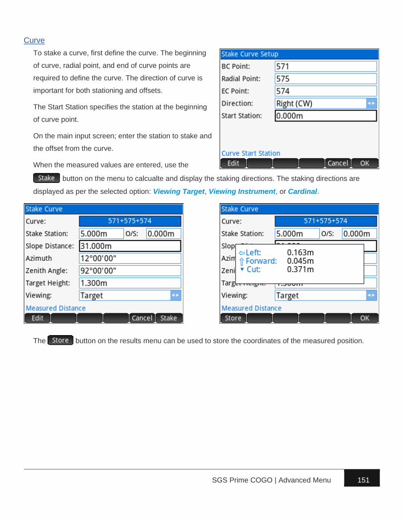
SGS Prime COGO | Advanced Menu 151
Curve
To stake a curve, first define the curve. The beginning
of curve, radial point, and end of curve points are
required to define the curve. The direction of curve is
important for both stationing and offsets.
The Start Station specifies the station at the beginning
of curve point.
On the main input screen; enter the station to stake and
the offset from the curve.
When the measured values are entered, use the
button on the menu to calcualte and display the staking directions. The staking directions are
displayed as per the selected option: Viewing Target, Viewing Instrument, or Cardinal.
The button on the results menu can be used to store the coordinates of the measured position.

SGS Prime COGO | Advanced Menu 152
Alignment
To stake any station and offfset along an alignment; the alignment must already be created.
On the main input screen; select the alignment to use, then enter the station and offset to stake.
When the measured values are entered, use the button on the menu to calcualte and display
the staking directions. The staking directions are displayed as per the selected option: Viewing Target,
Viewing Instrument, or Cardinal.
The button on the results menu can be used to store the coordinates of the measured position.

SGS Prime COGO | Advanced Menu 153
Slope
To stake a slope, first define the line from which the
slope calculations will be determined. Two points are
used to define the line, the order of which are important
when specifying offsets and slope.
The Start Station specifies the station at the first point of
the baseline.
On the main input screen; enter the slope to stake.
When the measured values are entered, use the
button on the menu to calcualte and display
the cut/fill amounts. The station and offset relative to the line are also displayed.
The button on the results menu can be used to store the coordinates of the measured position.

SGS Prime COGO | Advanced Menu 154
Reference
Reference calculations generally work by specifying a
reference geometry, and then obtaining information to
report the measured position relative to the geometry.
The reference geometry can be a line, curve or
alignment.
Line
To measure relative to a reference line, first define the
line. Two points are used to define the line, the order of
which are important to determine offsets.
The Start Station specifies the station at the first point of
the baseline.
When the measured values are entered, use the
button on the menu to calcualte and display
the position relative to the line. The forward/back
distances are on the current line of sight to intersect the
reference geometry, and are displayed as per the selected option: Viewing Target, or Viewing
Instrument.
The button on the results menu can be used to store the coordinates of the measured position.

SGS Prime COGO | Advanced Menu 155
Curve
To measure relative to a reference curve, first define the
curve. The beginning of curve, radial point, and end of
curve points are required to define the curve. The
direction of curve is important for both stationing and
offsets.
The Start Station specifies the station at the beginning
of curve point.
When the measured values are entered, use the
button on the menu to calcualte and display
the position relatve to the curve. The forward/back distances are on the current line of sight to intersect
the reference geometry, and are displayed as per the selected option: Viewing Target, or Viewing
Instrument.
The button on the results menu can be used to store the coordinates of the measured position.

SGS Prime COGO | Advanced Menu 156
Alignment
To measure relative to an alignment; the alignment must already be created.
On the main input screen; select the alignment to use, then enter the station and offset to stake.
When the measured values are entered, use the button on the menu to calcualte and display
the position relative to the alignment.
The button on the results menu can be used to store the coordinates of the measured position.

SGS Prime COGO | Advanced Menu 157
Tools
Traverse Plus 3D tools are necessary or handy utilities
that are related to the measurment data. Additional
tools will be added in a future release.
Configure Settings
Settings make it possible to add flexibility to how
Traverse Plus 3D operates.
► Mode – 2D mode disables zenith angle and
target height fields for measurements, and
requires horizontal distance measurements. 3D
mode enables all fields and allows a choice of
entering horizontal or slope distances.
► Horizontal Angles – Set true Azimuth or Angle
Right input for horizontal angles.
► Distances – Set Slope or Horizontal input for
distances. 2D mode only supports horizontal.
► Coordinates – Within the Measure application this setting determines if the coordinates of the
measured point are displayed prior to storing the point.
Inverse Calculations
Opens the Inverse Calculations options to eliminate the need to exit Traverse Plus 3D to calculate
inverses.
Close
Closes Traverse Plus 3D and returns to the main menu.

SGS Prime COGO | Advanced Menu 158
Coordinate Converter
The Coordinate Converter includes the following
coordinate conversion capabilities:
1. Grid↔Geodetic↔Cartesian – Convert between grid
coordinates, geodetic coordinates, and cartesian
coordinates.
2. Grid1→Grid2 (Single Point) – Convert a coordinate
position from one grid projection to another. Input
can be grid, geodetic, or cartesian coordinates.
3. Grid1→Grid2 (Convert Database) – Convert points
in the project database from one grid projection to
another.
4. Grid↔Ground (Single Point) – Convert coordinates of a single point between grid and ground based
on supplied parameters.
5. Grid↔Ground (Convert Database) – Convert points in the database between grid and ground based
on supplied parameters.
Grid↔Geodetic↔Cartesian
Convert between grid coordinates, geodetic coordinates, and cartesian coordinates using the current
Coordinate System settings. Input can be grid coordinates (N,E,h), geodetic coordinates (Φ,λ,h),
cartesian coordinates (x,y,z), or grid coordinates from a point in the database.
Results include all three coordinate representations, the point grid/elevation/combined factors, and the
grid convergence angle at the point.

SGS Prime COGO | Advanced Menu 159
Grid1→Grid2 (Single Point)
Convert a coordinate position from one grid projection
to another. Both grid projections, the transformation
method and the transformations parameters are
selected prior to calculation. Available transformation
methods include:
► No Transformation – Generally if both grid
projections are based on the same ellipsoid,
then no transformation is required.
► Dual Step (via WGS84) – When an
intermediate reference frame is required to
convert to and from. Frequently the transformation parameters are known to convert to WGS84,
in this case the user MUST define the transformation parameters for both Transform 1 and
Transform 2 to be TOWGS84. The first step transforms to WGS84 with the supplied parameters
directly, the second step transforms from WGS84 by changing the signs of the transformation
parameters. This is done to eliminate the need to have two sets of transformation parameters for
typical use. See the Transformation Parameters section for more information.
► Single Step (Direct) – When the transformation parameters to convert directly from one
reference frame to another are known.
Input can be grid coordinates (N,E,h), or grid coordinates from a point in the database. The vertical
system from the Coordinate System settings is used for height entry. See elevations note next page.
The results include the position of the point in the second projection, the point grid/elevation/combined
factors, the grid convergence angle at the point, and the geodetic coordinates of the point.

SGS Prime COGO | Advanced Menu 160
NOTE: When using transformations to transform points between projections based on different ellipsoids,
the Vertical System should be set to Ellipsoidal to obtain meaningful height results.
Grid1→Grid2 (Convert Database)
Convert points in the project database from one grid projection to another. Both grid projections, the
transformation method and the transformations parameters are selected prior to calculation. See
previous section for more information on available transformation methods.
Next, enter the point range to convert the coordinates in the database and specify how to store the new
coordinates.
Transformation Parameters
A default NULL transformation is included, it does
nothing but can be useful in some cases. All other
transformations can be defined as 3 or 7 parameter
transformations. The menu can be used to create new
transformations and edit or delete existing ones. Other
types of transformations:
► Bursa/Wolf – Use the 7 Parameter in lieu of.
► 4 Parameter – Use the 7 Parameter and set the 3
rotations to zero.
► 6 Parameter – Use the 7 Parameter and set the
scale parameter to zero.
► Molodensky – Use the 3 Parameter in lieu of.

SGS Prime COGO | Advanced Menu 161
Grid↔Ground (Single Point)
Land surveyors will often work with “ground-level” coordinates to eliminate the need to correct for a scale
factor for distance/area/volume calculations; but for various reasons they also require the “geo-
referenced” grid positions of their coordinates for other purposes. The grid/ground conversion tool is
created to make the conversion from one to the other a simple task for any/all points in a project.
The parameters are defined and stored separately for
each project and include:
1. A base point from which any scaling and rotation is
done. This can be set to the coordinate system
origin 0,0,0.
2. The base point horizontal coordinates in the
converted system (ground or grid). This can often
be a common point with the same coordinates in
both grid and ground, in which case the Use Base
option applies. The shift is calculated between the
base point and the given coordinates.
3. The base point elevation in the converted system (ground or grid). The shift is calculated between
the base point and the given elevation.
4. The scale factor to scale the horizontal coordinates from the base point.
5. The scaling method, either multiply or divide by the given scale factor.
6. The rotation angle to rotate from the base point.
When the parameters are defined; enter any point number in the database to convert.

SGS Prime COGO | Advanced Menu 162
Grid↔Ground (Convert Database)
Convert multiple points in the database between grid
and ground based on supplied parameters. See the
previous section for information about the conversion
parameters.
When the parameters are defined; enter the point range
to convert the coordinates in the database and specify
how to store the new coordinates.

SGS Prime COGO | Advanced Menu 163
Ellipsoid Calculations
DIRECT and INVERSE Computations on the ellipsoid
are implemented using Vincenty’s equations.
Position input for both types of calculations can be grid
coordinates (N,E,h), geodetic coordinates (Φ,λ,h),
cartesian coordinates (x,y,z), or grid coordinates from a
point in the database.
DIRECT Computation
Enter the position of the first point in any of the available formats and provide the forward azimuth and
ellipsoidal distance to the second point.
The solution shows:
► The grid coordinates of the second point, the grid direction and grid distance to the second point
► The geodetic coordinates of the second point and the back azimuth.
► The cartesian coordinates of the second point.

SGS Prime COGO | Advanced Menu 164
INVERSE Computation
Enter the positions of two points in any of the available formats
The solution shows:
► The grid direction, grid distance, the average combined factor and the ground distance between the
two points.
► The ellipsoid distance, the forward and back azimuths between the two points.
► The cartesian deltas, and the 3D point to point vector length.

SGS Prime COGO | Appendix A 165
The table below includes the parameters used for the ellipsoid definitions in SGS Prime COGO.
𝑏 = 𝑎 × (1 − 𝑓) 𝑓 = (𝑎 − 𝑏) ÷ 𝑎
𝑒′ = √𝑎2 − 𝑏2
𝑎2 𝑒′′ = √
𝑎2 − 𝑏2
𝑏2
Reference Ellipsoid Defining and Calculated Parameters
Clarke 1866 (NAD27) a = 6378206.4 b = 6356583.8 f = 0.00339007530392879 1/f = 294.978698213898
GRS80 (NAD83) a = 6378137 b = 6356752.31414036 f = 0.00335281068118232 1/f = 298.257222101
WGS84 a = 6378137 b = 6356752.31424518
f = 0.00335281066474748 1/f = 298.257223563
International 1924 (Hayford) a = 6378388 b = 6356911.94612795
f = 0.00336700336700337 1/f = 297
Clarke 1880 (ARC) a = 6378249.145 b = 6356514.96639875
f = 0.00340754619444173 1/f = 293.4663077
Clarke 1880 (IGN) a = 6378249.2 b = 6356515 f = 0.00340754952001565 1/f = 293.466021293627
Clarke 1880 (RGS) a = 6378249.145 b = 6356514.86954978
f = 0.00340756137869933 1/f = 293.465
Airy 1830 a = 6377563.396 b = 6356256.90923729
f = 0.00334085064149708 1/f = 299.3249646
Airy 1830 (Modified) a = 6377340.189 b = 6356034.44745858
f = 0.00334085071675583 1/f = 299.3249575
Australian National Spheroid a = 6378160 b = 6356774.71919531
f = 0.00335289186923722 1/f = 298.25
Krassovsky 1940 a = 6378245 b = 6356863.01877305
f = 0.00335232986925913 1/f = 298.3
Bessel 1841 a = 6377397.155 b = 6356078.96345955
f = 0.00334277308160762 1/f = 299.1528218
Parametry Zemli 1990 (PZ-90) a = 6378136 b = 6356751.30156878
f = 0.00335281317789691 1/f = 298.257


![Building Professionals Board v Cogo [2009] NSWADT 10bpb.nsw.gov.au/sites/default/files/public/Disciplinary actions... · Building Professionals Board v Cogo [2009] ... and the history](https://static.fdocuments.in/doc/165x107/5aa43f4c7f8b9a185d8bbe09/building-professionals-board-v-cogo-2009-nswadt-10bpbnswgovausitesdefaultfilespublicdisciplinary.jpg)

