SGS Prime COGO - sgss.ca · SGS Prime COGO | Installation 6 Upgrade to new Version To preserve...
103
SGS PRIME COGO Version 1 - Reference Manual March 18, 2018 https://sgss.ca/
Transcript of SGS Prime COGO - sgss.ca · SGS Prime COGO | Installation 6 Upgrade to new Version To preserve...
1
1 Installation .............................................................................................................................. 5 New Installation ................................................................................................................................... 5
Upgrade to new Version ...................................................................................................................... 6
Running SGS Prime COGO ................................................................................................................. 7
License Key ......................................................................................................................................... 8
2 Main Menu and User Interface .............................................................................................. 9 Main Menu Screen ............................................................................................................................... 9
About Screen ..................................................................................................................................... 11
Project Manager Shortcut .................................................................................................................. 11
User Settings Shortcut ....................................................................................................................... 11
Points Database Shortcut .................................................................................................................. 12
Keyboard ........................................................................................................................................... 13
Input Forms ....................................................................................................................................... 14
Copy and Paste ................................................................................................................................. 14
Point IDs ............................................................................................................................................ 15
Point Ranges ..................................................................................................................................... 15
Directions .......................................................................................................................................... 15
Angles ............................................................................................................................................... 16
Distances ........................................................................................................................................... 16
Coordinates ....................................................................................................................................... 17
Stations ............................................................................................................................................. 17
Grades ............................................................................................................................................... 17
Text ................................................................................................................................................... 17
Choose Lists ...................................................................................................................................... 18
Checkboxes ....................................................................................................................................... 18
Choose Boxes ................................................................................................................................... 19
Output Screens .................................................................................................................................. 19
3 User Settings ........................................................................................................................ 20 Angle and Distance Units................................................................................................................... 20
Angle Unit .......................................................................................................................................... 20
Angle Precision .................................................................................................................................. 20
Direction Reference ........................................................................................................................... 20
Distance Unit ..................................................................................................................................... 21
Distance Precision ............................................................................................................................. 21
Foot Definition ................................................................................................................................... 21
Coordinates, Stations and Grades ..................................................................................................... 22
Coordinate Display ............................................................................................................................ 22
Coordinate Precision ......................................................................................................................... 22
Stationing Display .............................................................................................................................. 22
Stationing Precision ........................................................................................................................... 22

2
Grade Display .................................................................................................................................... 22
Grade Precision ................................................................................................................................. 22
Input and Output Scale Factors ......................................................................................................... 23
Input Scale Factor.............................................................................................................................. 23
Apply Input Scale Factor .................................................................................................................... 23
Inverse? ............................................................................................................................................. 23
Output Scale Factor ........................................................................................................................... 23
Apply Output Scale Factor ................................................................................................................. 23
Program Options ............................................................................................................................... 24
Radius Tolerance............................................................................................................................... 24
Point Traverse 2D App ...................................................................................................................... 24
Time/Date .......................................................................................................................................... 24
DXF File Layers ................................................................................................................................. 24
Settings Use and Application ............................................................................................................. 25
4 COGO Menu .......................................................................................................................... 26 Point Traverse 2D .............................................................................................................................. 26
Point Traverse Standard .................................................................................................................... 26
Point Traverse Basic .......................................................................................................................... 31
Point Traverse Basic with Backsight .................................................................................................. 32
Curve Traverse Mode ........................................................................................................................ 33
Inverse Calculations ......................................................................................................................... 34
Inverse Points .................................................................................................................................... 34
Inverse Curve (Radial Point) .............................................................................................................. 37
Inverse Curve (Three Point) ............................................................................................................... 37
Inverse Angle ..................................................................................................................................... 39
Inverse Point to Line .......................................................................................................................... 39
Inverse Point to Curve ....................................................................................................................... 40
Intersections ...................................................................................................................................... 41
Bearing-Bearing ................................................................................................................................. 41
Distance-Distance.............................................................................................................................. 42
Bearing-Distance ............................................................................................................................... 43
Distance-Interior Angle ...................................................................................................................... 44
Areas / Closures ................................................................................................................................ 45
Area by Points ................................................................................................................................... 45
Subdivide by Sliding Bearing/Azimuth ................................................................................................ 47
Subdivide by Hinge Point ................................................................................................................... 48
Closures ............................................................................................................................................ 49
Fit Points .......................................................................................................................................... 53
Fit to Straight Line.............................................................................................................................. 53
Fit to Circular Curve ........................................................................................................................... 55
Double Proportion .............................................................................................................................. 57
Irregular Boundary Adjustment .......................................................................................................... 59
Grant Boundary Adjustment ............................................................................................................... 61

3
5 Adjust Menu.......................................................................................................................... 62 Compass Rule ................................................................................................................................... 62
Closed Figure .................................................................................................................................... 62
Close to Fixed Point ........................................................................................................................... 64
Rotate/Mirror Points ........................................................................................................................... 66
Rotate around Base Point .................................................................................................................. 66
Rotate around Origin (0,0) ................................................................................................................. 67
Mirror along Baseline ......................................................................................................................... 67
Shift/Average Points .......................................................................................................................... 68
Shift by ΔX/ΔY/ΔZ.............................................................................................................................. 68
Shift by Distance/Direction/ΔZ ........................................................................................................... 69
Shift by From/To Points ..................................................................................................................... 69
Average Points .................................................................................................................................. 70
Scale Points....................................................................................................................................... 71
Scale from Base Point ....................................................................................................................... 71
Scale from Origin (0,0,0) .................................................................................................................... 72
Transform Coordinates ...................................................................................................................... 73
Helmert Transformation ..................................................................................................................... 73
3D to Plan Cross Section ................................................................................................................... 76
6 Tools Menu ........................................................................................................................... 77 Triangle Solver .................................................................................................................................. 77
Horizontal Curves .............................................................................................................................. 78
Circular Curve Solver ......................................................................................................................... 78
Curve Through Fixed Point ................................................................................................................ 79
Spiral Curve Solver ............................................................................................................................ 80
Vertical Curves .................................................................................................................................. 82
Grades and Length known ................................................................................................................. 83
Elevations and Length known ............................................................................................................ 84
Fixed Point, VPI and Grades known .................................................................................................. 85
Fixed Point, BVC and Grades known ................................................................................................. 86
Intersect Slopes from two known points ............................................................................................. 87
Solution Screen and Calculations ...................................................................................................... 88
RPN Calculator .................................................................................................................................. 90
Main Interface .................................................................................................................................... 90
Configure Settings ............................................................................................................................. 93
7 Points Menu .......................................................................................................................... 94 Store and Edit Points ......................................................................................................................... 94
Point ID .............................................................................................................................................. 94
Delete Points ..................................................................................................................................... 95
Renumber Points ............................................................................................................................... 96
By Starting Number ........................................................................................................................... 96
By Additive Number ........................................................................................................................... 97
Plot Points ......................................................................................................................................... 98
Using Touch ...................................................................................................................................... 98

4
Using the Keyboard ........................................................................................................................... 98
Using the Menu ................................................................................................................................. 98
Import/Export ..................................................................................................................................... 99
Import ASCII points ............................................................................................................................ 99
Export ASCII points ......................................................................................................................... 100
Export DXF Points ........................................................................................................................... 101
8 Advanced Menu .................................................................................................................. 102 Alignments ....................................................................................................................................... 102
Leveling ........................................................................................................................................... 102
Traverse Plus 3D ............................................................................................................................. 102
Coordinate Converter ...................................................................................................................... 102
Ellipsoid Calculations ....................................................................................................................... 102
SGS Prime COGO | Installation 5
Install the SGS Prime COGO application for HP Prime on any of the following devices:
► Physical HP Prime Graphing Calculators
► Virtual Calculators for Windows or Mac
► Windows UWP HP Prime Pro app
► Android HP Prime Pro app
► iOS HP Prime Pro app
Required: Installation requires the Connectivity Kit for Windows or Mac.
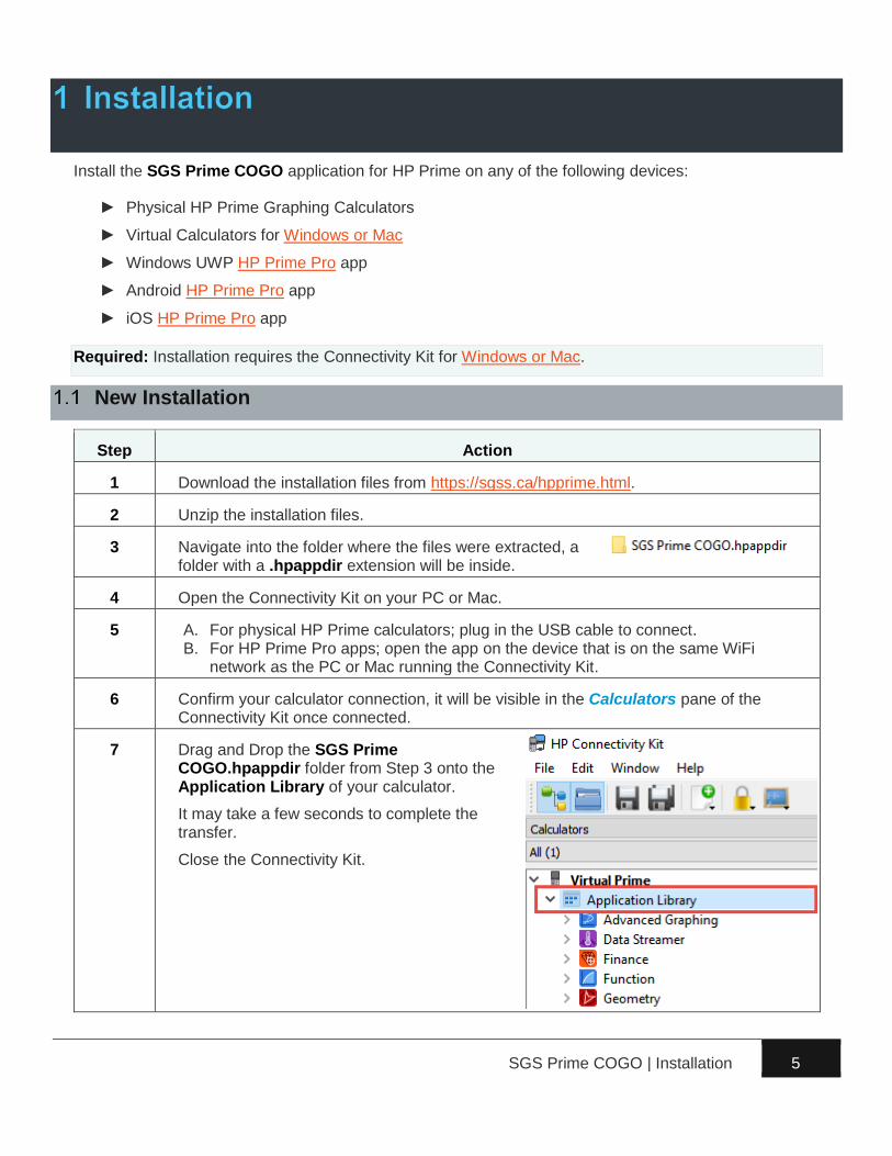
New Installation
Step Action
1 Download the installation files from https://sgss.ca/hpprime.html.
2 Unzip the installation files.
3 Navigate into the folder where the files were extracted, a folder with a .hpappdir extension will be inside.
4 Open the Connectivity Kit on your PC or Mac.
5 A. For physical HP Prime calculators; plug in the USB cable to connect. B. For HP Prime Pro apps; open the app on the device that is on the same WiFi
network as the PC or Mac running the Connectivity Kit.
6 Confirm your calculator connection, it will be visible in the Calculators pane of the Connectivity Kit once connected.
7 Drag and Drop the SGS Prime COGO.hpappdir folder from Step 3 onto the Application Library of your calculator.
It may take a few seconds to complete the transfer.
Close the Connectivity Kit.
SGS Prime COGO | Installation 6
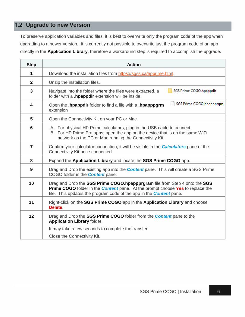
Upgrade to new Version
To preserve application variables and files, it is best to overwrite only the program code of the app when
upgrading to a newer version. It is currently not possible to overwrite just the program code of an app
directly in the Application Library, therefore a workaround step is required to accomplish the upgrade.
Step Action
1 Download the installation files from https://sgss.ca/hpprime.html.
2 Unzip the installation files.
3 Navigate into the folder where the files were extracted, a folder with a .hpappdir extension will be inside.
4 Open the .hpappdir folder to find a file with a .hpapppgrm extension
5 Open the Connectivity Kit on your PC or Mac.
6 A. For physical HP Prime calculators; plug in the USB cable to connect. B. For HP Prime Pro apps; open the app on the device that is on the same WiFi
network as the PC or Mac running the Connectivity Kit.
7 Confirm your calculator connection, it will be visible in the Calculators pane of the Connectivity Kit once connected.
8 Expand the Application Library and locate the SGS Prime COGO app.
9 Drag and Drop the existing app into the Content pane. This will create a SGS Prime COGO folder in the Content pane.
10 Drag and Drop the SGS Prime COGO.hpappprgram file from Step 4 onto the SGS Prime COGO folder in the Content pane. At the prompt choose Yes to replace the file. This updates the program code of the app in the Content pane.
11 Right-click on the SGS Prime COGO app in the Application Library and choose Delete.
12 Drag and Drop the SGS Prime COGO folder from the Content pane to the Application Library folder.
It may take a few seconds to complete the transfer.
Close the Connectivity Kit.

SGS Prime COGO | Installation 7
Running SGS Prime COGO
Once installed, run SGS Prime COGO by one of the following methods:
1. Open the Application Library on your calculator by
using the ! key. Locate the SGS Prime COGO
app and tap the icon or Start on the menu to open
the application.
or
2. From the Home or CAS screen, if SGS Prime
COGO is the active application with the title visible
at the top of the screen, use the N key to start
the application.
Other shortcut keys available from the Home or CAS
screen:
► @ starts the RPN Calculator.
► P opens the Plot Points program.
► S and @ / P / N opens the User Settings options.
SGS Prime COGO | Installation 8
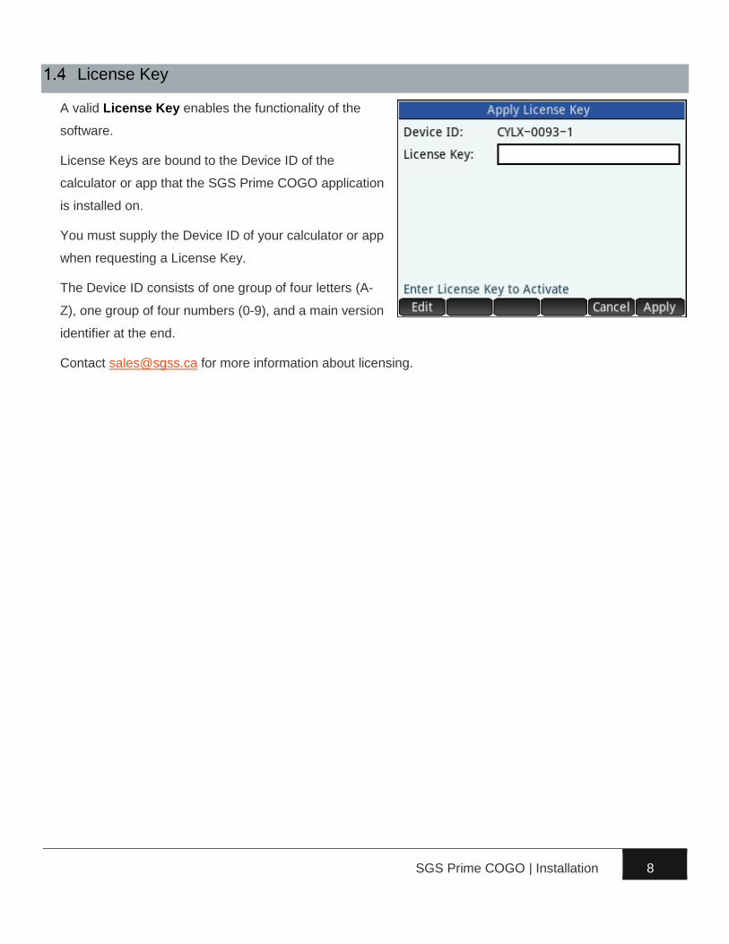
License Key
A valid License Key enables the functionality of the
software.
License Keys are bound to the Device ID of the
calculator or app that the SGS Prime COGO application
is installed on.
You must supply the Device ID of your calculator or app
when requesting a License Key.
The Device ID consists of one group of four letters (A-
Z), one group of four numbers (0-9), and a main version
identifier at the end.
Contact [email protected] for more information about licensing.

SGS Prime COGO | Main Menu and User Interface 9
SGS Prime COGO is designed for touch and keyboard navigation.
Main Menu Screen
The user interface displays program settings and provides access to all program functions. The diagram
below illustrates the screen layout.
See the next two pages for descriptions of the various components.

SGS Prime COGO | Main Menu and User Interface 10
Item Description
Current Settings
Displays some of the available user settings.
► DMS (360° ‘ “) D.d° (360° decimal) GON (400 gons) indicates current
Angle Unit setting.
► |N (North Azimuth) |S (South Azimuth) |QB (Quadrant Bearings)
indicates current direction reference setting.
► Metres (Metres) IFeet (International Feet) USFeet (US Survey Feet)
indicates the current Distance Unit setting.
► N,E (Northing Easting) E,N (Easting Northing) X,Y (X-Coord, Y-
Coord) indicates current coordinate order and label setting.
NOTE: Tap on this area to display the About screen.
Shortcuts Often used functions are available on all main interface screens.
Current Project Displays the current project name, the number of points stored in the
current project, and the next available Point ID that will be suggested.
Menu Options
Displays the titles of all menus, with the active menu name highlighted.
► COGO menu
► Adjust menu
► Tools menu
► Points menu
► Advanced menu
Program
Selection
Displays the available programs within each menu, with the currently
selected program name highlighted.

SGS Prime COGO | Main Menu and User Interface 11
About Screen
Tap the top of the main menu to display the About
screen. The program version and license information is
shown.
Enter a New Key. This will be necessary
when upgrading an existing license from Lite to
Standard, or Standard to Professional.
Project Manager Shortcut
Tap to access the Project Manager. Available options:
Create a new Project. The name is entered, and common user settings are selected. Some of
the User settings are stored with each project while others are applied to all projects; see the User
Settings chapter for details.
Delete the selected project. A confirmation prompt is displayed.
Load the selected project.
User Settings Shortcut
Tap to access the User Settings. See the User Settings chapter.
SGS Prime COGO | Main Menu and User Interface 12
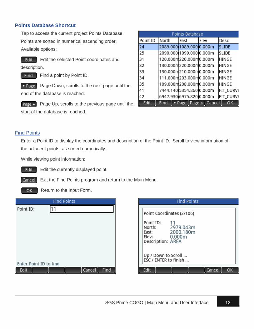
Points Database Shortcut
Tap to access the current project Points Database.
Points are sorted in numerical ascending order.
Available options:
Edit the selected Point coordinates and
description.
Find a point by Point ID.
Page Down, scrolls to the next page until the
end of the database is reached.
Page Up, scrolls to the previous page until the
start of the database is reached.
Find Points
Enter a Point ID to display the coordinates and description of the Point ID. Scroll to view information of
the adjacent points, as sorted numerically.
While viewing point information:
Edit the currently displayed point.
Exit the Find Points program and return to the Main Menu.
Return to the Input Form.
SGS Prime COGO | Main Menu and User Interface 13
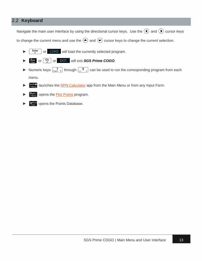
Keyboard
Navigate the main user interface by using the directional cursor keys. Use the L and R cursor keys
to change the current menu and use the U and D cursor keys to change the current selection.
► ~ or will load the currently selected program.
► & or O or will exit SGS Prime COGO.
► Numeric keys 1 through 5 can be used to run the corresponding program from each
menu.
► @ launches the RPN Calculator app from the Main Menu or from any Input Form.
► P opens the Plot Points program.
► V opens the Points Database.

SGS Prime COGO | Main Menu and User Interface 14
Input Forms
Input forms are used throughout the program to accept multiple different types of input. Some common
input types are: Point IDs / Point Ranges / Directions / Angles / Distances / Coordinates / Stations /
Grades / Text / Choose Lists / Checkboxes
Each input form will have some of the same basic elements, such as the Title, Field Labels, Input Fields,
Help Text and a Menu. The touch screen and keyboard can be used to select fields.
Current display settings control the appearance of each field.
NOTE: The RPN Calculator app can be launched from any input form by using the @ key.
Copy and Paste
While editing a field, the menu will display two options:
Copy the value that is being edited to the program’s clipboard. No need to ‘select’ the value,
the entire edit line will be copied. S and V can also be used to copy.
Paste the previously copied value from the clipboard into the edit line, replacing the current
content of the edit line. S and M can also be used to paste.
The Copy and Paste functionality is the best method to transfer calculated values to/from an Input Form
and the RPN Calculator.
SGS Prime COGO | Main Menu and User Interface 15
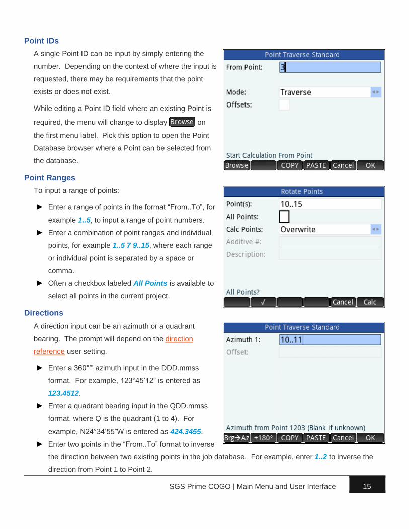
Point IDs
A single Point ID can be input by simply entering the
number. Depending on the context of where the input is
requested, there may be requirements that the point
exists or does not exist.
While editing a Point ID field where an existing Point is
required, the menu will change to display on
the first menu label. Pick this option to open the Point
Database browser where a Point can be selected from
the database.
Point Ranges
To input a range of points:
► Enter a range of points in the format “From..To”, for
example 1..5, to input a range of point numbers.
► Enter a combination of point ranges and individual
points, for example 1..5 7 9..15, where each range
or individual point is separated by a space or
comma.
► Often a checkbox labeled All Points is available to
select all points in the current project.
Directions
A direction input can be an azimuth or a quadrant
bearing. The prompt will depend on the direction
reference user setting.
► Enter a 360°’” azimuth input in the DDD.mmss
format. For example, 123°45’12” is entered as
123.4512.
► Enter a quadrant bearing input in the QDD.mmss
format, where Q is the quadrant (1 to 4). For
example, N24°34’55”W is entered as 424.3455.
► Enter two points in the “From..To” format to inverse
the direction between two existing points in the job database. For example, enter 1..2 to inverse the
direction from Point 1 to Point 2.
SGS Prime COGO | Main Menu and User Interface 16
► Subtract or add angles to/from a line direction by entering “From..To+Angle” or “From..To-Angle”.
For example, 1..2+30.3055 will inverse the direction from Point 1 to Point 2 and add 30°30’55” to it.
► Perform complex calculations using standard algebraic entry with current angle unit settings. For
example, 1..2+30.17-2.35-1.44 will inverse the direction from Point 1 to Point 2, then add 30°17’,
then subtract 2°35’, and then subtract another 1°44’.
► Repeat the last entry by entering ++ as input.
► While editing a direction field, pick this option to convert between bearings and azimuths.
► While editing a direction field, pick this option to reverse the direction.
Angles
Angles work in a similar fashion as azimuths/bearings except that the input MUST be a real number or a
complex calculation involving only real numbers.
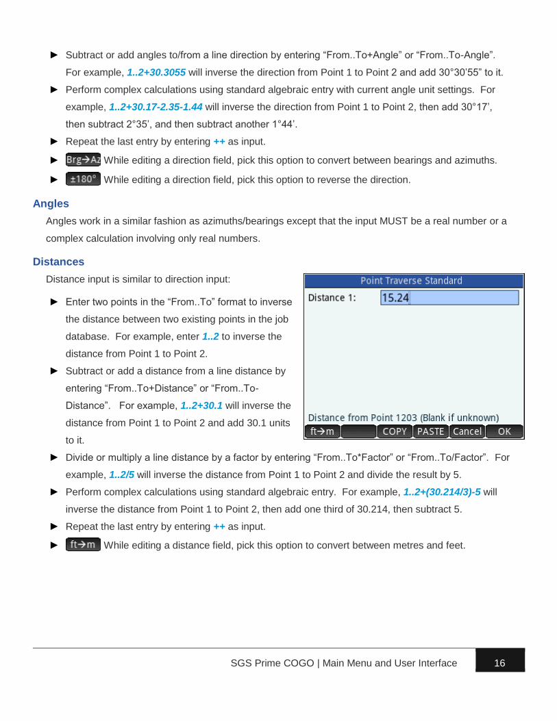
Distances
Distance input is similar to direction input:
► Enter two points in the “From..To” format to inverse
the distance between two existing points in the job
database. For example, enter 1..2 to inverse the
distance from Point 1 to Point 2.
► Subtract or add a distance from a line distance by
entering “From..To+Distance” or “From..To-
Distance”. For example, 1..2+30.1 will inverse the
distance from Point 1 to Point 2 and add 30.1 units
to it.
► Divide or multiply a line distance by a factor by entering “From..To*Factor” or “From..To/Factor”. For
example, 1..2/5 will inverse the distance from Point 1 to Point 2 and divide the result by 5.
► Perform complex calculations using standard algebraic entry. For example, 1..2+(30.214/3)-5 will
inverse the distance from Point 1 to Point 2, then add one third of 30.214, then subtract 5.
► Repeat the last entry by entering ++ as input.
► While editing a distance field, pick this option to convert between metres and feet.

SGS Prime COGO | Main Menu and User Interface 17
Coordinates
Coordinate values must be entered as real numbers, or as complex calculation involving real numbers.
Coordinates are displayed with current unit suffix once entered.
Stations
Station values must be entered as real numbers, or as complex calculation involving real numbers.
Stations are displayed with current station format once entered, 0+00 / 0+000 / No Format.
Grades
Grade values must be entered as real numbers, or as complex calculation involving real numbers.
Grades are displayed with grades format once entered, % (V/H*100) / Ratio V:H / Ratio H:V.
Text
Text fields will accept a certain range of characters as valid input. Use A and S to enter the
characters required. Available characters include:
Default:
1 2 3 4 5 6 7 8 9 0 . , + - * /
A enabled:
A B C D E F G H I J K L M N O P Q R S T U V W X Y Z # : . ;
A and S enabled:
a b c d e f g h i j k l m n o p q r s t u v w x y z # : = _ ;
SGS Prime COGO | Main Menu and User Interface 18
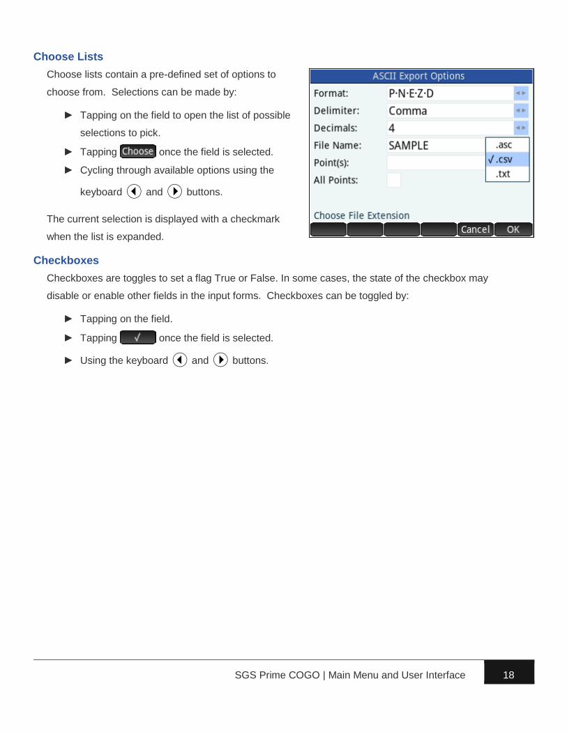
Choose Lists
Choose lists contain a pre-defined set of options to
choose from. Selections can be made by:
► Tapping on the field to open the list of possible
selections to pick.
► Tapping once the field is selected.
► Cycling through available options using the
keyboard L and R buttons.
The current selection is displayed with a checkmark
when the list is expanded.
Checkboxes
Checkboxes are toggles to set a flag True or False. In some cases, the state of the checkbox may
disable or enable other fields in the input forms. Checkboxes can be toggled by:
► Tapping on the field.
► Tapping once the field is selected.
► Using the keyboard L and R buttons.
SGS Prime COGO | Main Menu and User Interface 19
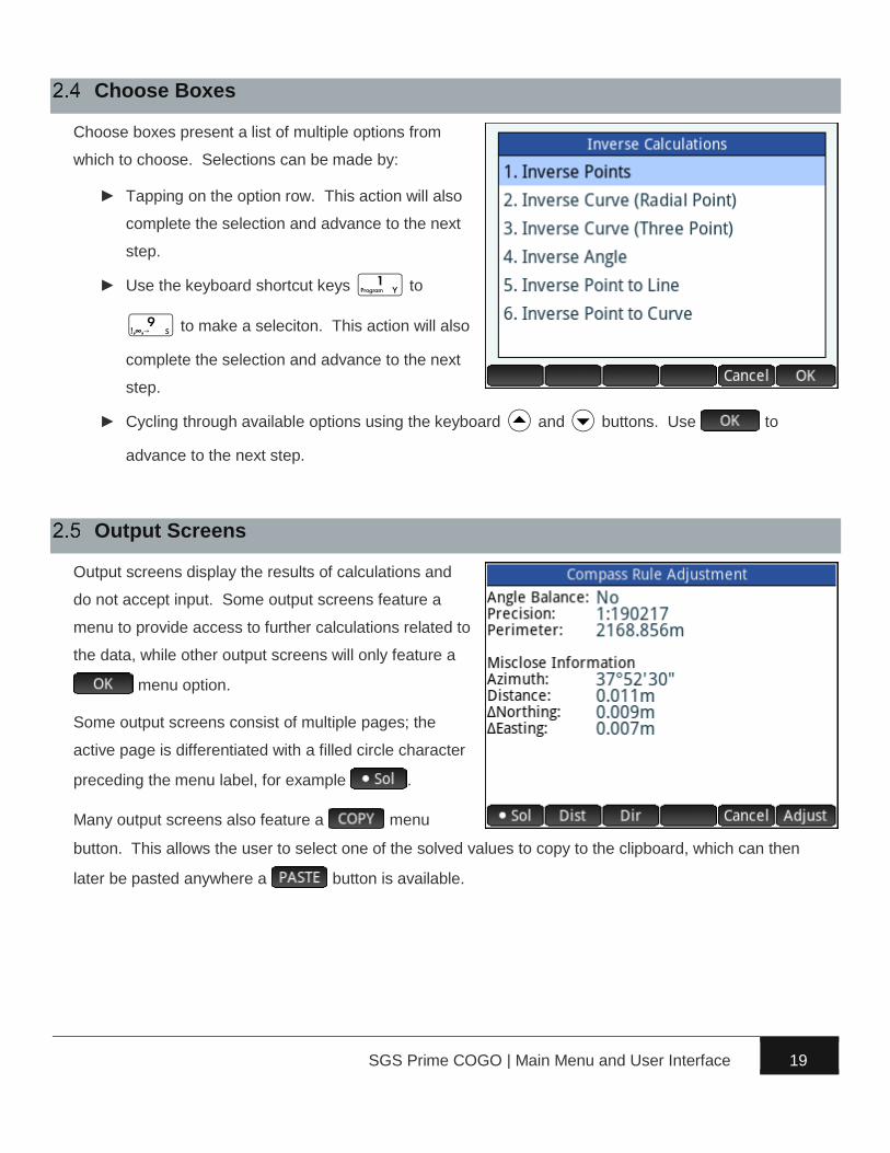
Choose Boxes
Choose boxes present a list of multiple options from
which to choose. Selections can be made by:
► Tapping on the option row. This action will also
complete the selection and advance to the next
step.
► Use the keyboard shortcut keys 1 to
9 to make a seleciton. This action will also
complete the selection and advance to the next
step.
► Cycling through available options using the keyboard U and D buttons. Use to
advance to the next step.
Output Screens
Output screens display the results of calculations and
do not accept input. Some output screens feature a
menu to provide access to further calculations related to
the data, while other output screens will only feature a
menu option.
Some output screens consist of multiple pages; the
active page is differentiated with a filled circle character
preceding the menu label, for example .
Many output screens also feature a menu
button. This allows the user to select one of the solved values to copy to the clipboard, which can then
later be pasted anywhere a button is available.

SGS Prime COGO | User Settings 20
Various settings allow the user to configure the software
to function to his/her preference. It is important to
review all the settings prior to using the software to
ensure they are set to produce the desired results.
Angle and Distance Units
Unit settings affect input interpretation and
representation.
Angle Unit
The angle unit may be set to 360°’” dms, 360° dec or
400 gon. Angular and directional input and output will
honour this setting for all functions.
Angle Precision
Angles and directions are displayed with the specified
number of decimals.
Direction Reference
Direction reference may be set to North Azimuth, South Azimuth, or Quadrant Bearings.
► North azimuths are defined by declaring north to be 0° (or 0g) while south azimuths are defined
by declaring south to be 0° (or 0g), and then measuring the full circle in a clockwise direction.
Azimuth input and output are subject to both angle unit and direction reference settings.
► Quadrant bearings split the circle into NE, SE, SW, and NW quadrants,
always measuring angles from north or south towards east or west. Quadrants
are numbered 1-4 to facilitate fast input of quadrant bearings. For example, to
enter a bearing of N36°43’15”W; the user would enter 436.4315 because the
NW quadrant = quadrant 4.
SGS Prime COGO | User Settings 21
Distance Unit
The distance unit may be set to metres or feet for display and conversion purposes.
The distance unit setting DOES NOT AFFECT JOB COORDINATES. The distance unit is for
input/output display only. To convert a project from metric to imperial, or vice versa, use the Scale Points
option. This behaviour is consistent with how a CAD drawing operates. The coordinates are essentially
unit-less, and this setting determines input and output display/calculations.
Distance Precision
Distances are displayed with the specified number of decimals.
Foot Definition
The foot definition setting may be set to US Survey Foot or International Foot for use with all
conversions between metric and imperial.
► The definition of a US Survey Foot is exactly 1200⁄3937 metres, approximately 0.304800609601
metres.
► The definition of the International Foot is exactly 0.3048 metres.
SGS Prime COGO | User Settings 22
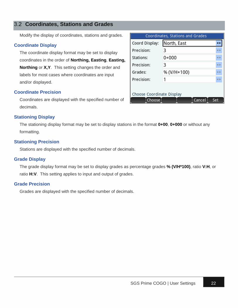
Coordinates, Stations and Grades
Modify the display of coordinates, stations and grades.
Coordinate Display
The coordinate display format may be set to display
coordinates in the order of Northing, Easting, Easting,
Northing or X,Y. This setting changes the order and
labels for most cases where coordinates are input
and/or displayed.
Coordinate Precision
Coordinates are displayed with the specified number of
decimals.
Stationing Display
The stationing display format may be set to display stations in the format 0+00, 0+000 or without any
formatting.
Stationing Precision
Stations are displayed with the specified number of decimals.
Grade Display
The grade display format may be set to display grades as percentage grades % (V/H*100), ratio V:H, or
ratio H:V. This setting applies to input and output of grades.
Grade Precision
Grades are displayed with the specified number of decimals.

SGS Prime COGO | User Settings 23
Input and Output Scale Factors
The Input Scale Factor, when enabled, is applied to all
distance entries to automatically scale the distance by
the specified scale factor. The Output Scale Factor,
when enabled, is applied to all calculated distances to
automatically scale the calculated distance. The
primary use of these settings is to calculate grid
coordinates by entering ground distances. The settings
can also be used to work with alternate units, such as
entering feet dimension in a metric project.
Input Scale Factor
The Input Scale Factor will be applied to any entered distance values when the toggle is set.
Apply Input Scale Factor
Toggle the application of the Input Scale Factor.
NOTE: When the Input Scale Factor is being applied, all distance input fields will display an asterisk after
the distance value once the input has been entered and parsed, for example 30.000m *.
Inverse?
Toggle the automatic calculation of the Inverse of the Input Scale Factor to set the Output Scale Factor.
Output Scale Factor
The Output Scale Factor will be applied to all calculated distances when the toggle is set.
Apply Output Scale Factor
Toggle the application of the Output Scale Factor.
NOTE: When the Output Scale Factor is being applied, all calculated distance values will be scaled by
this factor, and the resulting value will be displayed with an asterisk, for example 30.000m *.
.
SGS Prime COGO | User Settings 24
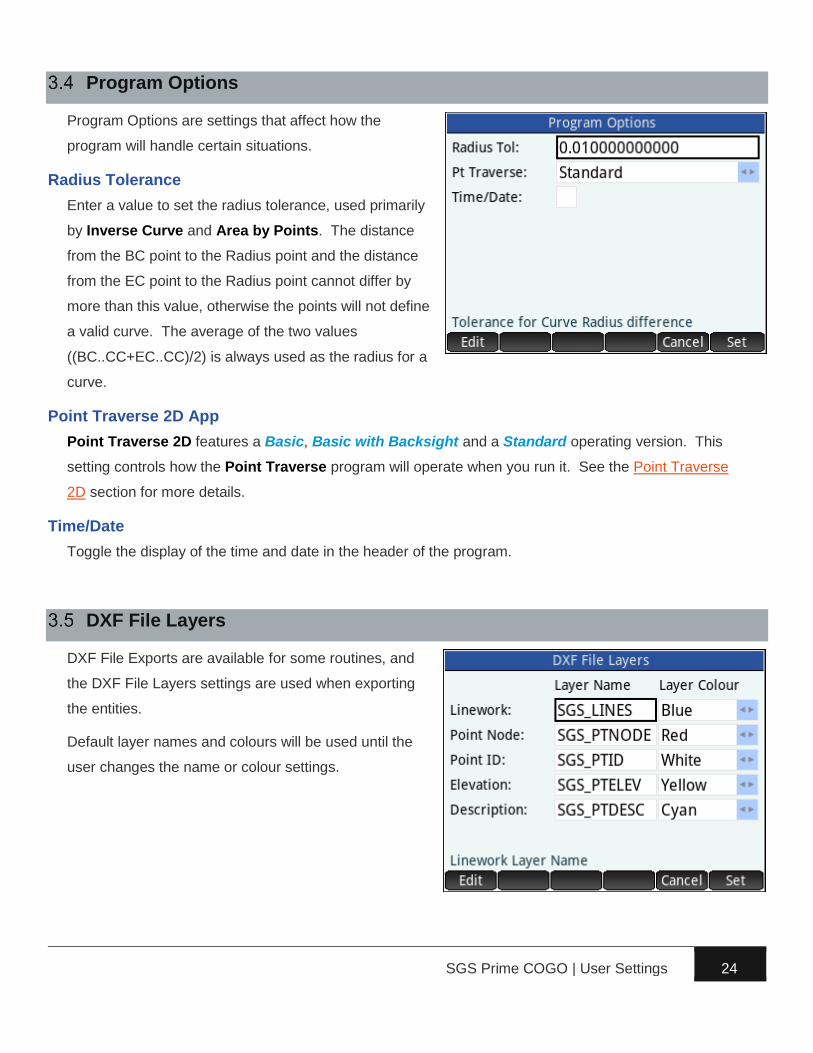
Program Options
Program Options are settings that affect how the
program will handle certain situations.
Radius Tolerance
Enter a value to set the radius tolerance, used primarily
by Inverse Curve and Area by Points. The distance
from the BC point to the Radius point and the distance
from the EC point to the Radius point cannot differ by
more than this value, otherwise the points will not define
a valid curve. The average of the two values
((BC..CC+EC..CC)/2) is always used as the radius for a
curve.
Point Traverse 2D App
Point Traverse 2D features a Basic, Basic with Backsight and a Standard operating version. This
setting controls how the Point Traverse program will operate when you run it. See the Point Traverse
2D section for more details.
Time/Date
Toggle the display of the time and date in the header of the program.
DXF File Layers
DXF File Exports are available for some routines, and
the DXF File Layers settings are used when exporting
the entities.
Default layer names and colours will be used until the
user changes the name or colour settings.
SGS Prime COGO | User Settings 25
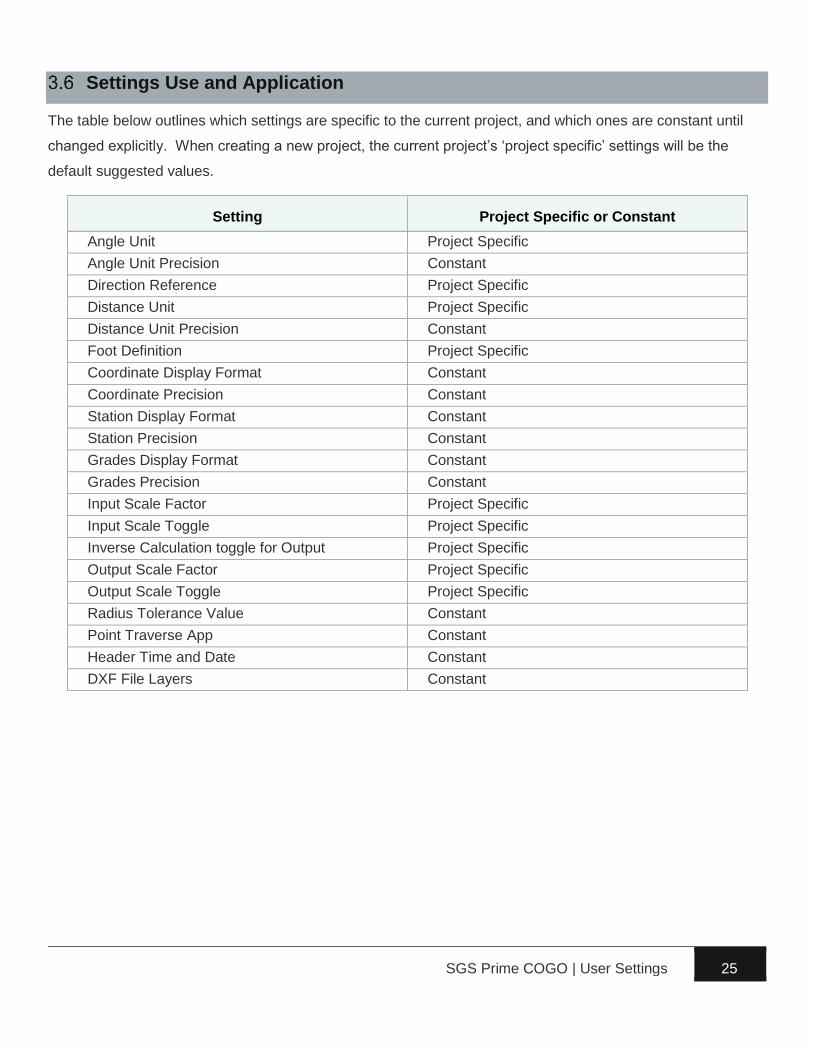
Settings Use and Application
The table below outlines which settings are specific to the current project, and which ones are constant until
changed explicitly. When creating a new project, the current project’s ‘project specific’ settings will be the
default suggested values.
Setting Project Specific or Constant
Angle Unit Project Specific
Angle Unit Precision Constant
Direction Reference Project Specific
Distance Unit Project Specific
Distance Unit Precision Constant
Foot Definition Project Specific
Coordinate Display Format Constant
Coordinate Precision Constant
Station Display Format Constant
Station Precision Constant
Grades Display Format Constant
Grades Precision Constant
Input Scale Factor Project Specific
Input Scale Toggle Project Specific
Inverse Calculation toggle for Output Project Specific
Output Scale Factor Project Specific
Output Scale Toggle Project Specific
Radius Tolerance Value Constant
Point Traverse App Constant
Header Time and Date Constant
DXF File Layers Constant

SGS Prime COGO | COGO Menu 26
► Point Traverse 2D – The primary COGO routine,
available in Basic and Standard mode.
► Inverse Calculations – Inverse Points, Inverse
Curve (Radial Point), Inverse Curve (Three
Point), Inverse Angle, Inverse Point to Line and
Inverse Point to Curve.
► Intersections – Bearing-Bearing, Distance-
Distance, Bearing-Distance and Distance-Interior Angle.
► Areas / Closures – Area by Points, Subdivide by Sliding Bearing, Subdivide by Hinge Point,
and Closures.
► Fit Points – Fit to Straight Line (Linear Regression), Fit to Circular Curve, Double Proportion,
Irregular Boundary and Grant Boundary.
Point Traverse 2D
Point Traverse 2D is the main COGO application and is available in three versions, Basic, Basic with
Backsight and Standard. The setting to switch between versions is under SETTINGS - PROGRAM
OPTIONS, and Standard is the default setting.
Point Traverse Standard
Point Traverse Standard is a complete COGO solution with Inverse and Intersection capabilities.
‘From Point’ Screen
The From Point input screen prompts the user to input
a point number to use as a starting point for further
calculations. Input types accepted:
1. An existing point number – The program ensures
the point exists.
2. A non-existing point number – The user may enter
a point number that has not yet been stored in the
database. An option to create the point will be
presented.
3. Two point numbers in the format “From..To” –
Calculate a point inverse between two points in the job. The From Point input screen is re-
SGS Prime COGO | COGO Menu 27
displayed after this input type is processed. For example, input 1..2 to calculate the inverse from
Point 1 to Point 2.
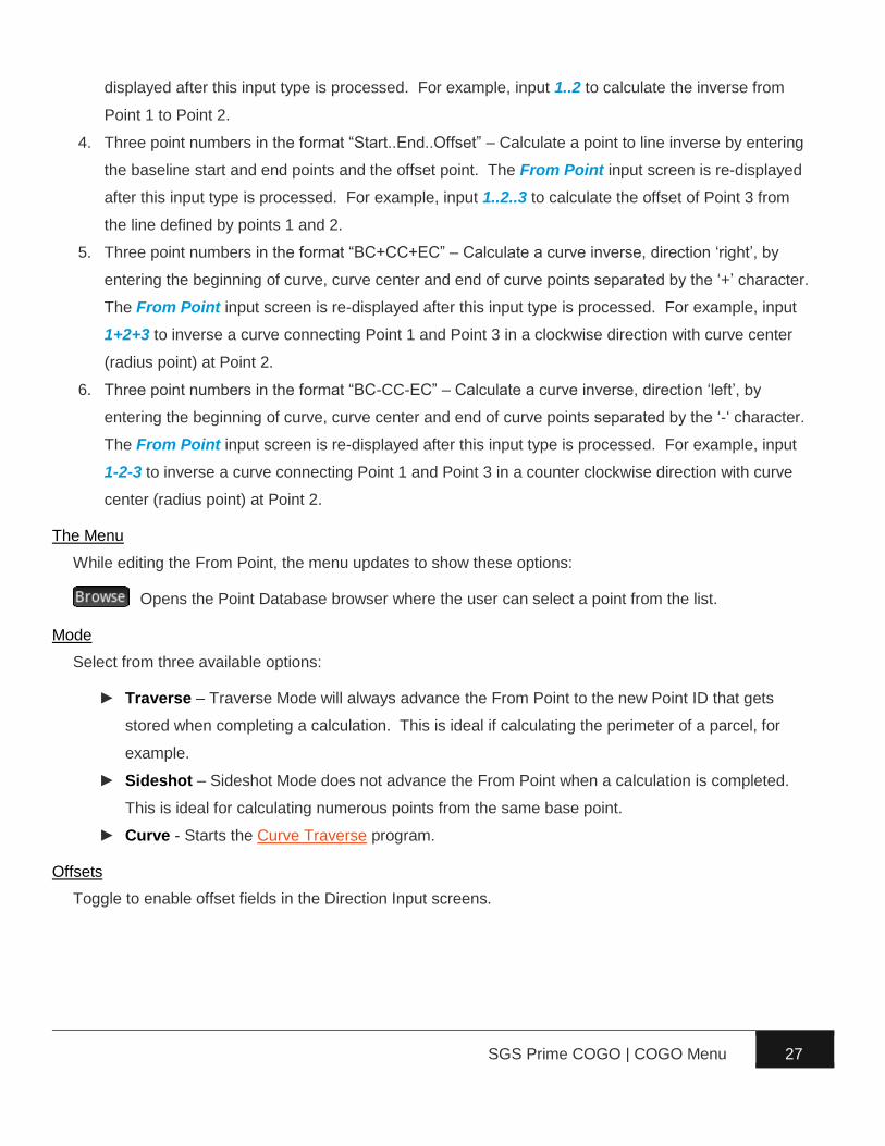
4. Three point numbers in the format “Start..End..Offset” – Calculate a point to line inverse by entering
the baseline start and end points and the offset point. The From Point input screen is re-displayed
after this input type is processed. For example, input 1..2..3 to calculate the offset of Point 3 from
the line defined by points 1 and 2.
5. Three point numbers in the format “BC+CC+EC” – Calculate a curve inverse, direction ‘right’, by
entering the beginning of curve, curve center and end of curve points separated by the ‘+’ character.
The From Point input screen is re-displayed after this input type is processed. For example, input
1+2+3 to inverse a curve connecting Point 1 and Point 3 in a clockwise direction with curve center
(radius point) at Point 2.
6. Three point numbers in the format “BC-CC-EC” – Calculate a curve inverse, direction ‘left’, by
entering the beginning of curve, curve center and end of curve points separated by the ‘-‘ character.
The From Point input screen is re-displayed after this input type is processed. For example, input
1-2-3 to inverse a curve connecting Point 1 and Point 3 in a counter clockwise direction with curve
center (radius point) at Point 2.
The Menu
While editing the From Point, the menu updates to show these options:
Opens the Point Database browser where the user can select a point from the list.
Mode
Select from three available options:
► Traverse – Traverse Mode will always advance the From Point to the new Point ID that gets
stored when completing a calculation. This is ideal if calculating the perimeter of a parcel, for
example.
► Sideshot – Sideshot Mode does not advance the From Point when a calculation is completed.
This is ideal for calculating numerous points from the same base point.
► Curve - Starts the Curve Traverse program.
Offsets
Toggle to enable offset fields in the Direction Input screens.

SGS Prime COGO | COGO Menu 28
‘Azimuth 1’ or ‘Bearing 1’ Screen
The direction reference setting determines whether
Azimuth or Bearing is displayed. This screen prompts
the user to input the azimuth or bearing to the new point
from the FROM POINT. Input types accepted:
1. Azimuth or Bearing – The real number entered is
interpreted based on the current angle unit and
direction reference user settings and the next
screen is displayed.
2. Any of the standard directions input options.
3. Leave blank, no input – Signals that the azimuth or bearing to the new point is unknown, which
leaves the possibility of a Distance-Bearing, or Distance-Distance intersection.
The Menu
While editing the Direction, the menu updates to show these options:
Converts the input between bearings and azimuths. The appearance and action
of this menu option varies depending on your direction reference setting.
Flips the direction of the number in the command line by adding/subtracting 180 degrees (or
200 gons).
Offset
When enabled, the offset field accepts a perpendicular offset distance from the FROM POINT.

SGS Prime COGO | COGO Menu 29
‘Distance 1’ Screen
This screen prompts the user to input the distance to
the new point from the FROM POINT. Input types
accepted:
1. A distance – The number entered is used as the
distance and the next screen is displayed.
2. Any of the standard distances input options.
3. Leave blank, no input – Signals that the distance to
the new point is unknown, which leaves the
possibility of a Bearing-Bearing or a Bearing-
Distance intersection, provided that the Azimuth 1
input was given.
The Menu
While editing the Distance, the menu updates to show these options:
or convert the input between metric and imperial units. The menu key varies depending
on your primary distance unit setting.
‘To Point’ Screen
This screen accepts the point number of a second
known point that an intersection calculation connects to.
This screen appears when either the Azimuth 1 or
Distance 1 inputs are unknown and left blank.

SGS Prime COGO | COGO Menu 30
‘Azimuth 2’ or ‘Bearing 2’ Screen
This screen has two possible variations depending on
whether Azimuth 1 or Distance 1 is known. In both
cases the screen prompts the user to enter the azimuth
or bearing from the new point that is being calculated
TO the second known point. This screen accepts the
same input types as the Azimuth 1 screen.
‘Distance 2’ Screen
This screen prompts the user to enter the distance from
the new point that is being calculated TO the second
known point. This screen accepts the same input types
as the Distance 1 screen.
‘Store Point’ Screen
The screen displays the coordinates of the solved point
and all the fields can be edited. The Point ID
suggestion will always be next unused Point ID after the
last stored point.
The Menu
While editing the Point ID, the menu updates to show
these Point ID searching options:
Inserts the lowest unused point number into
the command line.
Inserts the next lowest unused point number starting from the currently entered value.

SGS Prime COGO | COGO Menu 31
Point Traverse Basic
Point Traverse Basic is a COGO application that
accepts all input within a single input form.
‘From Point’ Field
This field requires an existing point number to use as
the starting point, or station. Entering a point number
that does not exist in the job will result in the option to
create a new point.
All the Inverse Calculation as described under the Point
Traverse Standard section are also accepted.
‘Azimuth’ or ‘Bearing’ Field
This field requires the direction to the new point from the FROM POINT. Input types accepted:
1. Azimuth or Bearing – The real number entered is interpreted based on the current angle unit and
direction reference user settings.
2. Any of the standard directions input options.
‘Distance’ Field
This field requires the distance to the new point from the FROM POINT. Input types accepted:
1. A distance – The number entered is used as the distance.
2. Any of the standard distances input options.
‘Offset’ Field
This field accepts a perpendicular offset value from the line of direction. A positive offset is to the right
while a negative offset is to the left. This field accepts the same types of inputs as the Distance field.
‘Mode’ Field
Select from three available options:
► Traverse – Traverse Mode will always advance the From Point to the new Point ID that gets
stored when completing a calculation. This is ideal if calculating the perimeter of a parcel, for
example.
► Sideshot – Sideshot Mode does not advance the From Point when a calculation is completed.
This is ideal for calculating numerous points from the same base point.
► Curve - Starts the Curve Traverse program.
SGS Prime COGO | COGO Menu 32
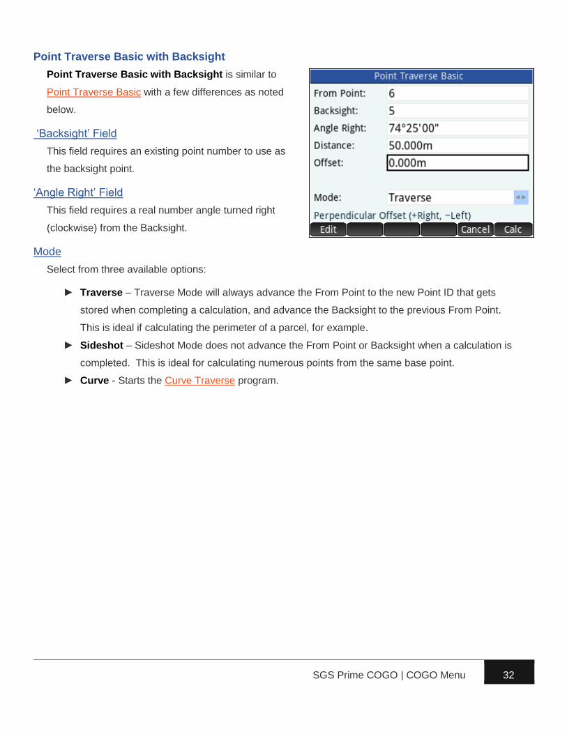
Point Traverse Basic with Backsight
Point Traverse Basic with Backsight is similar to
Point Traverse Basic with a few differences as noted
below.
‘Backsight’ Field
This field requires an existing point number to use as
the backsight point.
‘Angle Right’ Field
This field requires a real number angle turned right
(clockwise) from the Backsight.
Mode
Select from three available options:
► Traverse – Traverse Mode will always advance the From Point to the new Point ID that gets
stored when completing a calculation, and advance the Backsight to the previous From Point.
This is ideal if calculating the perimeter of a parcel, for example.
► Sideshot – Sideshot Mode does not advance the From Point or Backsight when a calculation is
completed. This is ideal for calculating numerous points from the same base point.
► Curve - Starts the Curve Traverse program.
SGS Prime COGO | COGO Menu 33
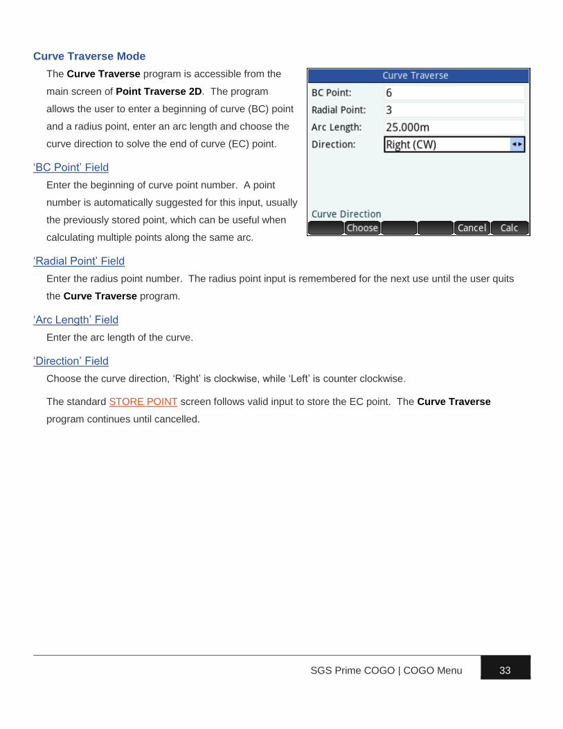
Curve Traverse Mode
The Curve Traverse program is accessible from the
main screen of Point Traverse 2D. The program
allows the user to enter a beginning of curve (BC) point
and a radius point, enter an arc length and choose the
curve direction to solve the end of curve (EC) point.
‘BC Point’ Field
Enter the beginning of curve point number. A point
number is automatically suggested for this input, usually
the previously stored point, which can be useful when
calculating multiple points along the same arc.
‘Radial Point’ Field
Enter the radius point number. The radius point input is remembered for the next use until the user quits
the Curve Traverse program.
‘Arc Length’ Field
Enter the arc length of the curve.
‘Direction’ Field
Choose the curve direction, ‘Right’ is clockwise, while ‘Left’ is counter clockwise.
The standard STORE POINT screen follows valid input to store the EC point. The Curve Traverse
program continues until cancelled.
SGS Prime COGO | COGO Menu 34
Inverse Calculations
Inverse Points, Inverse Curve (Radial Point), Inverse
Curve (Three Point), Inverse Angle, Inverse Point to
Line and Inverse Point to Curve are available options
for inversing with point coordinates in the current project
database.
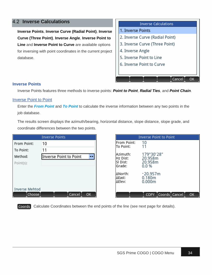
Inverse Points
Inverse Points features three methods to inverse points: Point to Point, Radial Ties, and Point Chain.
Inverse Point to Point
Enter the From Point and To Point to calculate the inverse information between any two points in the
job database.
The results screen displays the azimuth/bearing, horizontal distance, slope distance, slope grade, and
coordinate differences between the two points.
Calculate Coordinates between the end points of the line (see next page for details).

SGS Prime COGO | COGO Menu 35
Line Coordinate Calculator
When the Point to Point Inverse is calculated, further
calculations can be made between the end points of the
line.
By Station and Offset
Enter any Station and Offset to solve the coordinates.
The station at the beginning or end of the line is
required, then 3D coordinates are calculated at the
specified station and offset. The solved positions can
be stored in the project database with the option.
By Distance Interval or Equal Partitions
Calculate multiple points at a specific interval or by dividing the line into equal partitions.

SGS Prime COGO | COGO Menu 36
Inverse Radial Ties
Enter the From Point and a Range of Points to calculate radial ties to that range of points.
Three pages of results are available.
Displays directions and horizontal distances.
Displays slope distances and grades.
Displays differences in coordinates.
Inverse Point Chain
Enter a Range of Points to calculate a series of Point to Point inverses, as a chain connecting the
points.
SGS Prime COGO | COGO Menu 37
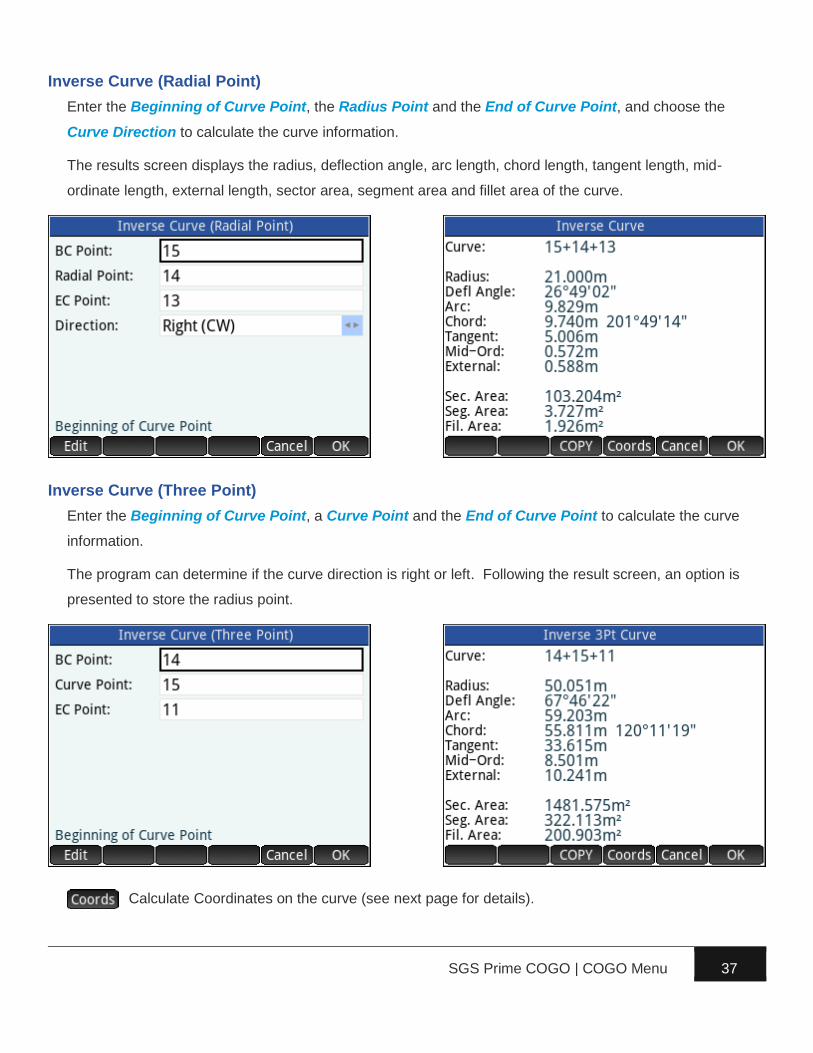
Inverse Curve (Radial Point)
Enter the Beginning of Curve Point, the Radius Point and the End of Curve Point, and choose the
Curve Direction to calculate the curve information.
The results screen displays the radius, deflection angle, arc length, chord length, tangent length, mid-
ordinate length, external length, sector area, segment area and fillet area of the curve.
Inverse Curve (Three Point)
Enter the Beginning of Curve Point, a Curve Point and the End of Curve Point to calculate the curve
information.
The program can determine if the curve direction is right or left. Following the result screen, an option is
presented to store the radius point.
Calculate Coordinates on the curve (see next page for details).

SGS Prime COGO | COGO Menu 38
Curve Coordinate Calculator
When the Point to Point Inverse is calculated, further
calculations can be made between the end points of the
line.
By Station and Offset
Enter any Station and Offset to solve the coordinates.
The station at the BC, PI, or EC of the curve is required,
then 3D coordinates are calculated at the specified
station and offset. The solved positions can be stored
in the project database with the option.
By Distance Interval or Equal Partitions
Calculate multiple points at a specific interval or by dividing the line into equal partitions.

SGS Prime COGO | COGO Menu 39
Inverse Angle
Enter the Occupy Point, the Backsight Point and the Foresight Point to calculate the included angle.
The results screen displays the angles turned right and left as well as the distances to the backsight and
foresight points from the occupy point.
Inverse Point to Line
Enter two points, Baseline P1 and Baseline P2, to define a baseline and an Offset Point to calculate
the perpendicular offset of the point to the line.
The results screen displays the offset from the baseline, Station 1 from Baseline P1 to a point along the
baseline that is perpendicular to the offset point, Station 2 to the same point from Baseline P2, the cut/fill
to the baseline and the length, direction and the grade of the baseline.
SGS Prime COGO | COGO Menu 40
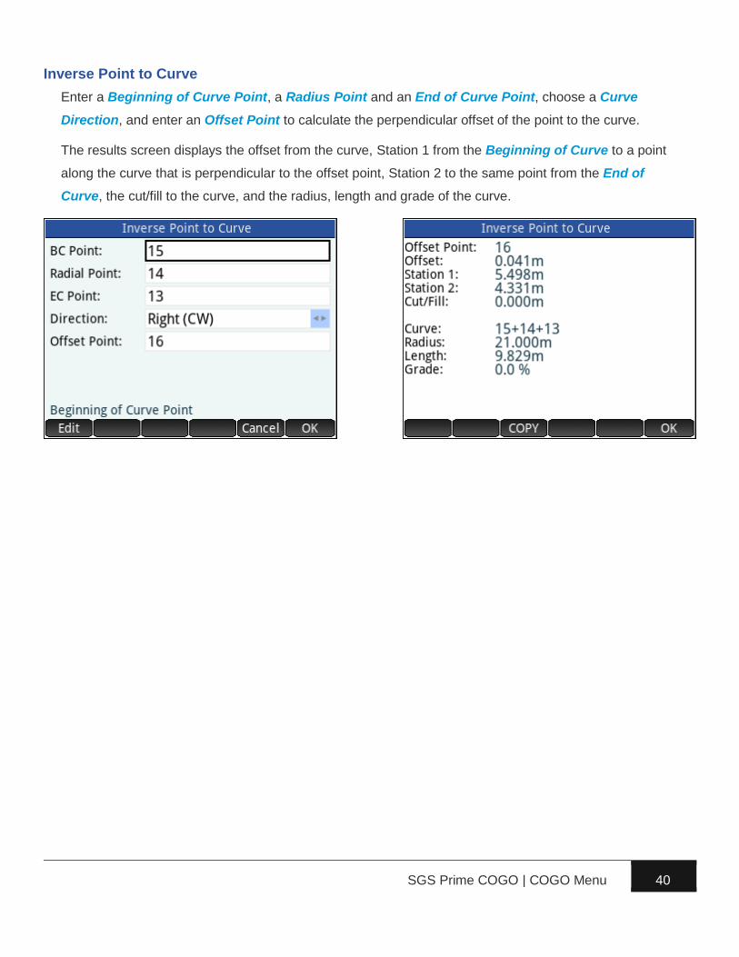
Inverse Point to Curve
Enter a Beginning of Curve Point, a Radius Point and an End of Curve Point, choose a Curve
Direction, and enter an Offset Point to calculate the perpendicular offset of the point to the curve.
The results screen displays the offset from the curve, Station 1 from the Beginning of Curve to a point
along the curve that is perpendicular to the offset point, Station 2 to the same point from the End of
Curve, the cut/fill to the curve, and the radius, length and grade of the curve.

SGS Prime COGO | COGO Menu 41
Intersections
The Intersections program can solve four types of
intersections.
In the diagram shown, the ‘1st Point’ and “2nd Point’ points are always
known points and the ‘New Point’ point can be calculated from the known
information.
Bearing-Bearing
A bearing-bearing intersection can be solved when BEARING1 and
BEARING2 are known. Offsets may be entered for both azimuth/bearing inputs.
New Point
1st Point
2nd Point
Interior Angle

SGS Prime COGO | COGO Menu 42
Distance-Distance
A distance-distance intersection can be solved when
DISTANCE1 and DISTANCE2 are known. This type of
intersection usually has two possible solutions. The
user is prompted to choose which of the two solutions is
desired by selecting one of the two possible solutions
from the first point.
SGS Prime COGO | COGO Menu 43
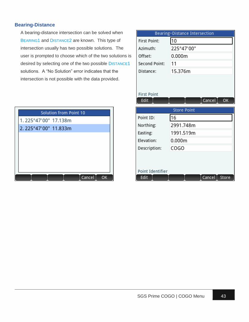
Bearing-Distance
A bearing-distance intersection can be solved when
BEARING1 and DISTANCE2 are known. This type of
intersection usually has two possible solutions. The
user is prompted to choose which of the two solutions is
desired by selecting one of the two possible DISTANCE1
solutions. A “No Solution” error indicates that the
intersection is not possible with the data provided.

SGS Prime COGO | COGO Menu 44
Distance-Interior Angle
A distance-interior angle intersection can be solved
when DISTANCE1 and the INTERIOR ANGLE at the new
point are known. This type of intersection can have up
to 4 possible solutions. The user is prompted to choose
the preferred solution.
SGS Prime COGO | COGO Menu 45
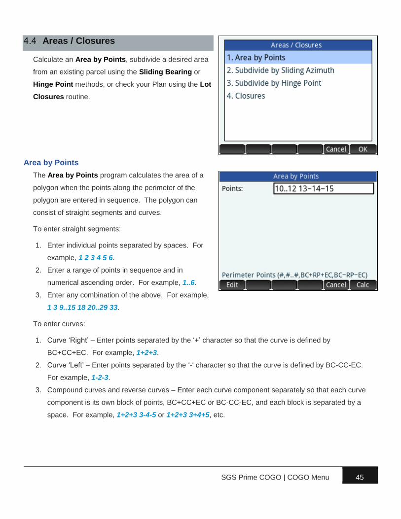
Areas / Closures
Calculate an Area by Points, subdivide a desired area
from an existing parcel using the Sliding Bearing or
Hinge Point methods, or check your Plan using the Lot
Closures routine.
Area by Points
The Area by Points program calculates the area of a
polygon when the points along the perimeter of the
polygon are entered in sequence. The polygon can
consist of straight segments and curves.
To enter straight segments:
1. Enter individual points separated by spaces. For
example, 1 2 3 4 5 6.
2. Enter a range of points in sequence and in
numerical ascending order. For example, 1..6.
3. Enter any combination of the above. For example,
1 3 9..15 18 20..29 33.
To enter curves:
1. Curve ‘Right’ – Enter points separated by the ‘+’ character so that the curve is defined by
BC+CC+EC. For example, 1+2+3.
2. Curve ‘Left’ – Enter points separated by the ‘-‘ character so that the curve is defined by BC-CC-EC.
For example, 1-2-3.
3. Compound curves and reverse curves – Enter each curve component separately so that each curve
component is its own block of points, BC+CC+EC or BC-CC-EC, and each block is separated by a
space. For example, 1+2+3 3-4-5 or 1+2+3 3+4+5, etc.
SGS Prime COGO | COGO Menu 46
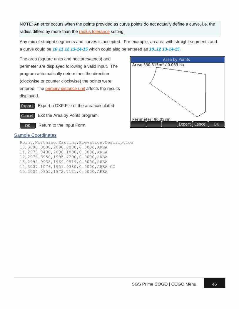
NOTE: An error occurs when the points provided as curve points do not actually define a curve, i.e. the
radius differs by more than the radius tolerance setting.
Any mix of straight segments and curves is accepted. For example, an area with straight segments and
a curve could be 10 11 12 13-14-15 which could also be entered as 10..12 13-14-15.
The area (square units and hectares/acres) and
perimeter are displayed following a valid input. The
program automatically determines the direction
(clockwise or counter clockwise) the points were
entered. The primary distance unit affects the results
displayed.
Export a DXF File of the area calculated
Exit the Area by Ponts program.
Return to the Input Form.
Sample Coordinates
Point,Northing,Easting,Elevation,Description
10,3000.0000,2000.0000,0.0000,AREA
11,2979.0430,2000.1800,0.0000,AREA
12,2976.3950,1995.4290,0.0000,AREA
13,2994.9938,1969.0919,0.0000,AREA
14,3007.1076,1951.9380,0.0000,AREA_CC
15,3004.0355,1972.7121,0.0000,AREA
SGS Prime COGO | COGO Menu 47
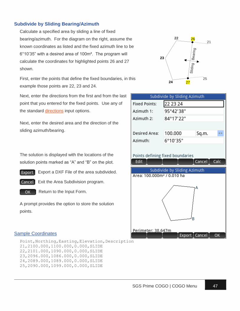
Subdivide by Sliding Bearing/Azimuth
Calculate a specified area by sliding a line of fixed
bearing/azimuth. For the diagram on the right, assume the
known coordinates as listed and the fixed azimuth line to be
6°10’35” with a desired area of 100m². The program will
calculate the coordinates for highlighted points 26 and 27
shown.
First, enter the points that define the fixed boundaries, in this
example those points are 22, 23 and 24.
Next, enter the directions from the first and from the last
point that you entered for the fixed points. Use any of
the standard directions input options.
Next, enter the desired area and the direction of the
sliding azimuth/bearing.
The solution is displayed with the locations of the
solution points marked as “A” and “B” on the plot.
Export a DXF File of the area subdivided.
Exit the Area Subdivision program.
Return to the Input Form.
A prompt provides the option to store the solution
points.
Sample Coordinates
Point,Northing,Easting,Elevation,Description
21,2100.000,1100.000,0.000,SLIDE
22,2101.000,1090.000,0.000,SLIDE
23,2096.000,1086.000,0.000,SLIDE
24,2089.000,1089.000,0.000,SLIDE
25,2090.000,1099.000,0.000,SLIDE
25
22 21
23
24 27
26
SGS Prime COGO | COGO Menu 48
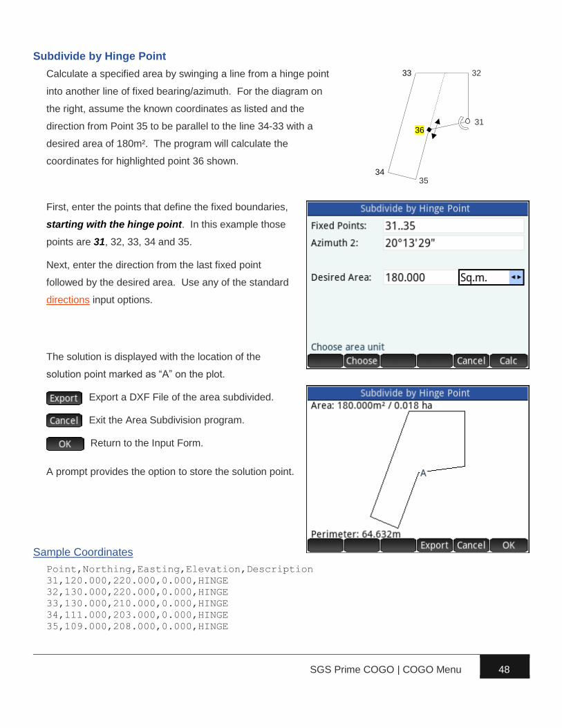
Subdivide by Hinge Point
Calculate a specified area by swinging a line from a hinge point
into another line of fixed bearing/azimuth. For the diagram on
the right, assume the known coordinates as listed and the
direction from Point 35 to be parallel to the line 34-33 with a
desired area of 180m². The program will calculate the
coordinates for highlighted point 36 shown.
First, enter the points that define the fixed boundaries,
starting with the hinge point. In this example those
points are 31, 32, 33, 34 and 35.
Next, enter the direction from the last fixed point
followed by the desired area. Use any of the standard
directions input options.
The solution is displayed with the location of the
solution point marked as “A” on the plot.
Export a DXF File of the area subdivided.
Exit the Area Subdivision program.
Return to the Input Form.
A prompt provides the option to store the solution point.
Sample Coordinates
Point,Northing,Easting,Elevation,Description
31,120.000,220.000,0.000,HINGE
32,130.000,220.000,0.000,HINGE
33,130.000,210.000,0.000,HINGE
34,111.000,203.000,0.000,HINGE
35,109.000,208.000,0.000,HINGE
33
36
35
32
31
34
SGS Prime COGO | COGO Menu 49
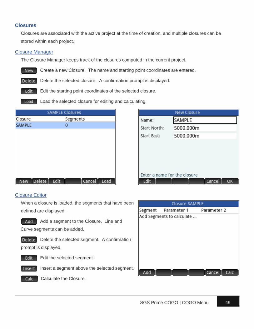
Closures
Closures are associated with the active project at the time of creation, and multiple closures can be
stored within each project.
Closure Manager
The Closure Manager keeps track of the closures computed in the current project.
Create a new Closure. The name and starting point coordinates are entered.
Delete the selected closure. A confirmation prompt is displayed.
Edit the starting point coordinates of the selected closure.
Load the selected closure for editing and calculating.
Closure Editor
When a closure is loaded, the segments that have been
defined are displayed.
Add a segment to the Closure. Line and
Curve segments can be added.
Delete the selected segment. A confirmation
prompt is displayed.
Edit the selected segment.
Insert a segment above the selected segment.
Calculate the Closure.

SGS Prime COGO | COGO Menu 50
Add Segment
When adding a segment, a choice is given to add a Line
or Curve segment.
Depending on the selection, the input for the new
segment is requested. Both the Line and Curve
Segment Input Forms continue in a loop until cancelled.
The Closure Editor displays the segments with their key
parameters once they are defined.
Delete Segment
Select a segment to delete and choose the menu
option. A confirmation is required.
Edit Segment
Select the segment to edit and choose the menu option.
The current information is loaded for editing.
Insert Segment
Select a segment and choose the menu option to insert a new segment before the selected segment.

SGS Prime COGO | COGO Menu 51
Closure Solution
When all the segments are defined, the Calculate option will display the results of the closure. The
Solution page shows the numeric results, while the Plot page will draw the segments.
Export Options
Four options are available to export the closure results.
► Add Closure Report to Log File – Adds the
current closure results to a ClosureLOG.txt file.
With this option it is possible to have numerous
closures reported in a single TEXT file for
printing, etc.
► Clear Log File – Clears the ClosureLOG.txt file
if it exists.
► Export HTML Report – Creates an HTML
report of the closure. The user can enter a file
name for the report, which can then be viewed in a web browser on a PC or Mac.
► Export DXF File – Creates a DXF file of the closure lines and curves. The user can enter a file
name for the DXF file, which can then be viewed in a CAD program on a PC or Mac.
► Store Point Coordinates – Store the points that define the closure. Coordinates are calculated
from the starting point coordinates for the closure. The user can enter a Starting Point ID and a
descriptor for the points.

SGS Prime COGO | COGO Menu 52
Sample Closure Report
Enter the lot dimensions to calculate the lot closure as
shown below. The most westerly corner was used as
the starting point, then counter-clockwise around the
perimeter. Arbitrary coordinates 5000,5000 were
assigned to the starting point.
SGS Prime COGO | COGO Menu 53
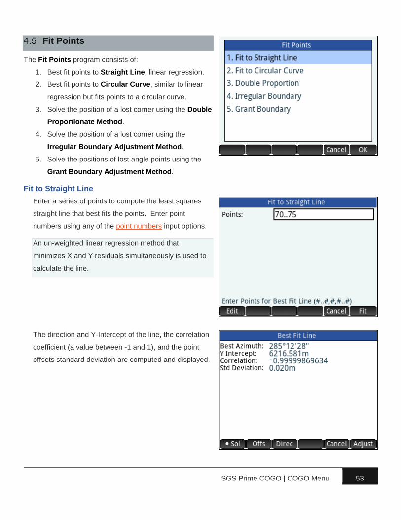
Fit Points
The Fit Points program consists of:
1. Best fit points to Straight Line, linear regression.
2. Best fit points to Circular Curve, similar to linear
regression but fits points to a circular curve.
3. Solve the position of a lost corner using the Double
Proportionate Method.
4. Solve the position of a lost corner using the
Irregular Boundary Adjustment Method.
5. Solve the positions of lost angle points using the
Grant Boundary Adjustment Method.
Fit to Straight Line
Enter a series of points to compute the least squares
straight line that best fits the points. Enter point
numbers using any of the point numbers input options.
An un-weighted linear regression method that
minimizes X and Y residuals simultaneously is used to
calculate the line.
The direction and Y-Intercept of the line, the correlation
coefficient (a value between -1 and 1), and the point
offsets standard deviation are computed and displayed.

SGS Prime COGO | COGO Menu 54
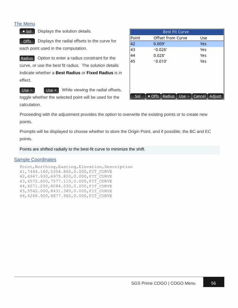
The Menu
Displays the solution details.
Displays the perpendicular offsets to the line
for each point used in the computation.
Option to enter a direction constraint for the
line, or use the best fit direction. The solution details
page indicates whether a Best Azimuth or Fixed
Azimuth is in effect.
While viewing the perpendicular
offsets, toggle whether the selected point will be used
for the calculation.
Proceeding with the adjustment provides the option to overwrite the existing points or to create new
points.
Points are shifted perpendicular to the best-fit line to minimize the shift.
Sample Coordinates
Point,Northing,Easting,Elevation,Description
70,5142.364,3951.682,0.000,FIT_LINE
71,5126.301,4010.781,0.000,FIT_LINE
72,5122.959,4022.875,0.000,FIT_LINE
73,5119.064,4037.366,0.000,FIT_LINE
74,5109.751,4071.672,0.000,FIT_LINE
75,5105.428,4087.524,0.000,FIT_LINE

SGS Prime COGO | COGO Menu 55
Fit to Circular Curve
The main purpose of this program is to calculate the radius and
the coordinates of the radius point of the least squares circle
that best fits a series of points. When providing points along
one or both tangents, the program will also solve the BC and/or
EC point coordinates.
In the input form, enter a series of points along the
curve to compute the circle that best fits the points.
Enter point numbers using any of the point numbers
input options.
Optional: Also enter points on the Tangent In/Out to
compute the BC/EC points. If specifying tangent points,
it is important to select the correct curve direction
Right/Left.
The curve solution displays the computed radius, the
radius standard deviation, the coordinates of the radius
point, and if applicable, the azimuths/bearings of the
back and forward tangents.
Point on back
tangent
Curve Points
Point on forward tangent
46
45 44
43 42 41
SGS Prime COGO | COGO Menu 56
The Menu
Displays the solution details.
Displays the radial offsets to the curve for
each point used in the computation.
Option to enter a radius constraint for the
curve, or use the best fit radius. The solution details
indicate whether a Best Radius or Fixed Radius is in
effect.
While viewing the radial offsets,
toggle whether the selected point will be used for the
calculation.
Proceeding with the adjustment provides the option to overwrite the existing points or to create new
points.
Prompts will be displayed to choose whether to store the Origin Point, and if possible; the BC and EC
points.
Points are shifted radially to the best-fit curve to minimize the shift.
Sample Coordinates
Point,Northing,Easting,Elevation,Description
41,7444.140,5354.860,0.000,FIT_CURVE
42,6947.930,6975.820,0.000,FIT_CURVE
43,6572.600,7577.110,0.000,FIT_CURVE
44,6071.290,8084.030,0.000,FIT_CURVE
45,5542.000,8431.380,0.000,FIT_CURVE
46,4268.900,8877.960,0.000,FIT_CURVE

SGS Prime COGO | COGO Menu 57
Double Proportion
“The term ‘double proportionate measurement’ is applied to a new measurement made between four
known corners, two each on intersecting meridional and latitudinal lines, for the purpose of relating the
cardinal equivalent intersection to both.” (Page 166, BLM Manual of Surveying Instructions 2009).
The Double Proportion program solves this type of
problem by accepting point numbers for the four known
corners, and the record measurements to the lost
corner.
The first input form requires existing point numbers of
the corners to the north, east, south and west of the lost
corner.
The second input form requires the record bearings and
distances to the known corners west and east of the lost
corner.
SGS Prime COGO | COGO Menu 58
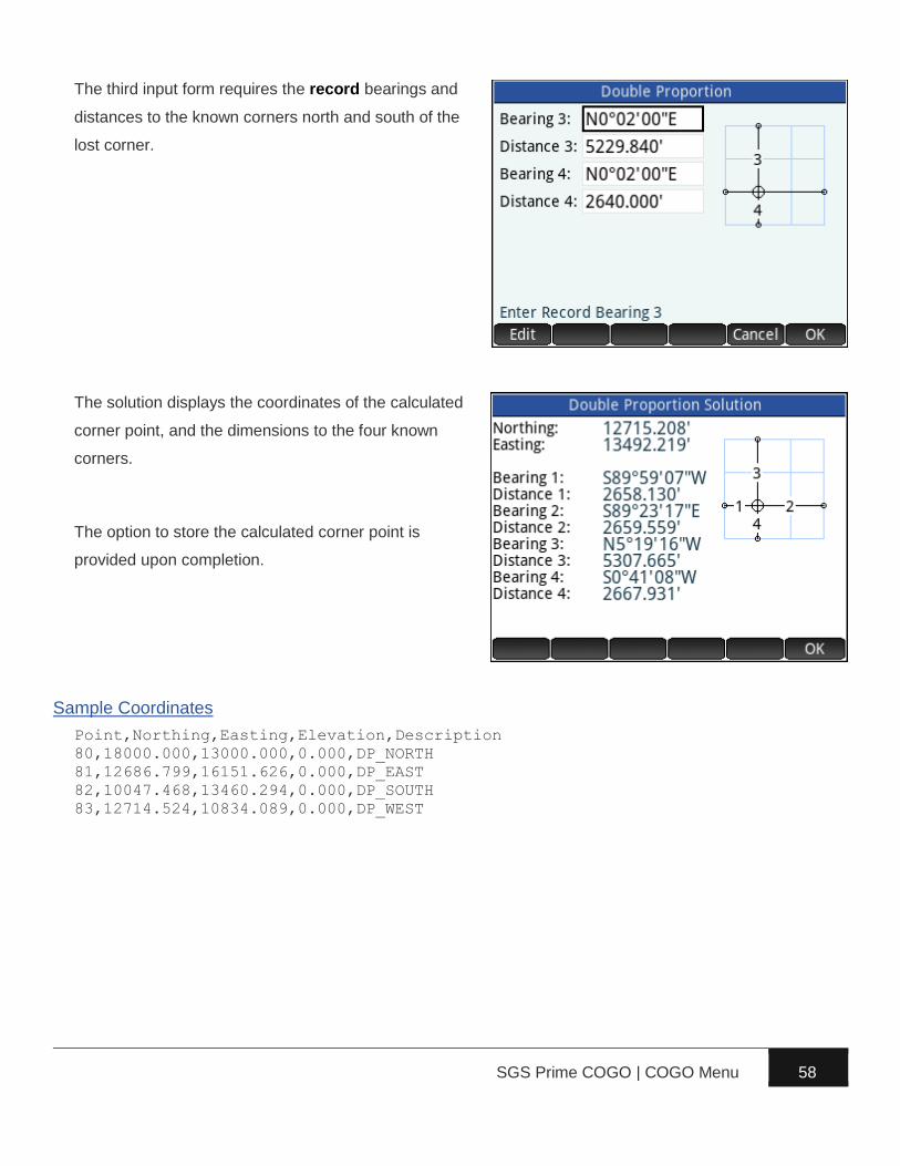
The third input form requires the record bearings and
distances to the known corners north and south of the
lost corner.
The solution displays the coordinates of the calculated
corner point, and the dimensions to the four known
corners.
The option to store the calculated corner point is
provided upon completion.
Sample Coordinates
Point,Northing,Easting,Elevation,Description
80,18000.000,13000.000,0.000,DP_NORTH
81,12686.799,16151.626,0.000,DP_EAST
82,10047.468,13460.294,0.000,DP_SOUTH
83,12714.524,10834.089,0.000,DP_WEST

SGS Prime COGO | COGO Menu 59
Irregular Boundary Adjustment
Irregular boundaries are the result of boundaries
surveyed from opposite directions, or piecemeal
surveys where resulting boundaries are not straight
lines. “In order to restore one or more lost corners or
angle points on such irregular exterior, a retracement
between the nearest known corners is made on the
record courses and distances to ascertain the direction
and length of the closing distance. A position is
calculated for each lost corner or angle point at the
record position.” (Page 174, BLM Manual of Surveying
Instructions 2009) A combination of single proportion and compass rule is then used to re-establish the
lost corner. The direction (East-West or North-South) determines how the adjustment is performed.
The Irregular Boundary program prompts for the
direction of the line, and then the first input form
requires the point numbers for the surveyed points (W +
E, or N + S).
The second input form requires the record dimensions
to the corners on either side of the lost corner.

SGS Prime COGO | COGO Menu 60
The solution displays the coordinates of the calculated
corner point, and the dimensions to the two known
corners.
The option to store the calculated corner point is
provided upon completion.
Sample Coordinates
Point,Northing,Easting,Elevation,Description
85,11000.000,18000.000,0.000,IB_SOUTH
86,16202.385,18075.912,0.000,IB_NORTH

SGS Prime COGO | COGO Menu 61
Grant Boundary Adjustment
“In many of the States there are irregular grant and reservation boundaries that were established prior to
the public rectangular surveys. In these cases, the township and section lines are regarded as the
closing lines. The grant boundary field notes may call for natural objects, but these are often
supplemented by metes-and-bounds descriptions. The natural calls are ordinarily given precedence then
the existent angle points of the metes-and-bounds survey. The lost angle points are then restored by
uniformly orienting the record courses to the left or right and adjusting the lengths of the lines on a
constant ration.” (Page 176, BLM Manual of Surveying Instructions 2009)
The Grant Boundary program requires a series of
points that define the grant boundary, starting with a
known (found) point followed by calculated points using
record dimensions. The first field asks for these points.
The second field asks for a Closing Point, which is a
found original point representing the last calculated
point that was entered. The spatial difference between
the closing point and the last calculated point
determines the adjustment parameters.
The calculated rotation and scale are displayed on the
results screen.
A choice is presented to adjust the record points.
Proceeding with the adjustment provides the option to
overwrite the existing points or to create new points.
Sample Coordinates
Point,Northing,Easting,Elevation,Descript
90,15000.0000,11000.0000,0.0000,GRANT
91,15008.3755,10990.0184,0.0000,GRANT
92,15027.8573,10960.0192,0.0000,GRANT
93,15136.4522,10883.9802,0.0000,GRANT
94,15136.4522,10776.6602,0.0000,GRANT
95,15126.4853,10744.0597,0.0000,GRANT
96,15123.7945,10667.0067,0.0000,GRANT
97,15123.7945,10638.7067,0.0000,GRANT
98,15084.8497,10558.8578,0.0000,GRANT
99,15103.3462,10518.4399,0.0000,GRANT

SGS Prime COGO | Adjust Menu 62
► Compass Rule – Perform a compass rule
adjustment on a Closed Figure or Close to
Known Point traverse.
► Rotate / Mirror – Rotate around Base Point,
Rotate around Origin (0,0) and Mirror along
Baseline.
► Shift / Average – Shift by ΔX/ΔY/Δ, Shift by
Distance/Direction/ΔZ, Shift by From/To Points and Average Points.
► Scale Points – Scale from Base Point, and Scale from Origin (0,0,0).
► Transform Coordinates – Helmert Transformation and 3D to Plan Cross Section.
Compass Rule
A “compass rule” or “bowditch rule” adjustment distributes the linear misclose of a traverse proportionally
throughout each leg of a traverse. A ‘closed figure’ traverse ends back on the starting point while a ‘close to
fixed point’ traverse ends on a known control point that is held fixed.
Closed Figure
A known starting point, followed by a series of intermediate
points, and ending back on the starting point defines a closed
figure. Prior to adjustment, the loop ending point coordinates
as measured will differ from the starting point coordinates.
The difference between these coordinates will be distributed
proportionally through each leg of the figure.
50
52
53
54
55
(56)
51

SGS Prime COGO | Adjust Menu 63
First, enter the point numbers using any of the point
numbers input options, and select the Adjustment Type.
Next, an option to Balance Angles is presented. If the
closing angle is known, choose “Yes”, otherwise choose
“No”.
If the user selected “Yes” to balance angles, an input
form will allow for the closing angle to be entered.
The COMPASS RULE RESULTS screen displays
information about the adjustment including the angle
balance information, precision, the perimeter of the
figure, and the misclose information.
Display the Adjustment Solution.
Display the unadjusted and adjusted distances
for each course of the traverse.
Display the unadjusted and adjusted
directions for each course of the traverse.
Proceed with adjusting the points.

SGS Prime COGO | Adjust Menu 64
Examples of the distance and direction result pages:
Proceeding with the adjustment will present the option
to Renumber or Overwrite the existing point numbers.
When renumbering, a description for the new points can
also be set.
Sample Coordinates
Point,Northing,Easting,Elevation,Descript
50,6102.894,4125.949,0.000,CRA_CLOSED
51,6120.510,4191.528,0.000,CRA_CLOSED
52,6096.092,4283.143,0.000,CRA_CLOSED
53,6023.426,4256.416,0.000,CRA_CLOSED
54,6056.123,4166.749,0.000,CRA_CLOSED
55,5995.827,4158.356,0.000,CRA_CLOSED
56,6102.885,4125.942,0.000,CRA_CLOSED
Close to Fixed Point
A close to fixed point traverse begins on a known control point
followed by a series of intermediate points and ends on a
second known control point which will be held fixed. The
difference between the measured ending point coordinates
and the fixed values will be distributed proportionally through
each leg of the traverse.
60
61
62
63 (69)
64

SGS Prime COGO | Adjust Menu 65
First, enter the point numbers using any of the point numbers input options, and select the Adjustment
Type. When a ‘Close to Fixed Point’ type is selected, the following input form will ask for the Fixed Point.
The COMPASS RULE RESULTS screen displays
information about the adjustment including the
precision, the length of the figure, and the misclose
information.
Display the Adjustment Solution.
Display the unadjusted and adjusted distances
for each course of the traverse.
Display the unadjusted and adjusted
directions for each course of the traverse.
Proceed with adjusting the points.
Sample Coordinates
Point,Northing,Easting,Elevation,Descript
60,7033.458,5311.207,0.000,CRA_KNOWN
61,7070.237,5360.793,0.000,CRA_KNOWN
62,7037.104,5460.587,0.000,CRA_KNOWN
63,7010.119,5550.529,0.000,CRA_KNOWN
64,7028.068,5612.263,0.000,CRA_KNOWN
69,7028.060,5612.266,0.000,CRA_KNOWN

SGS Prime COGO | Adjust Menu 66
Rotate/Mirror Points
Rotate Points around a base point or the coordinate
system origin, and Mirror Points mirrors points along a
baseline.
Rotate around Base Point
First, enter the point number to use as a base point.
Next, select if you’re entering a known rotation angle, or
if you are calculating the rotation angle from two
reference directions.
► Enter a positive angle for clockwise rotation and
a negative angle for a counter-clockwise
rotation.
► Use any of the standard directions input options
to enter reference directions.
Next, enter the points to rotate, and select how to store the newly calculated points.

SGS Prime COGO | Adjust Menu 67
Rotate around Origin (0,0)
Like Rotate Around Base Point, except no base point is required, the points will be rotated around 0,0.
Mirror along Baseline
First, enter two points to define a baseline.
Next, enter the points to mirror and specify how to store the new coordinates.
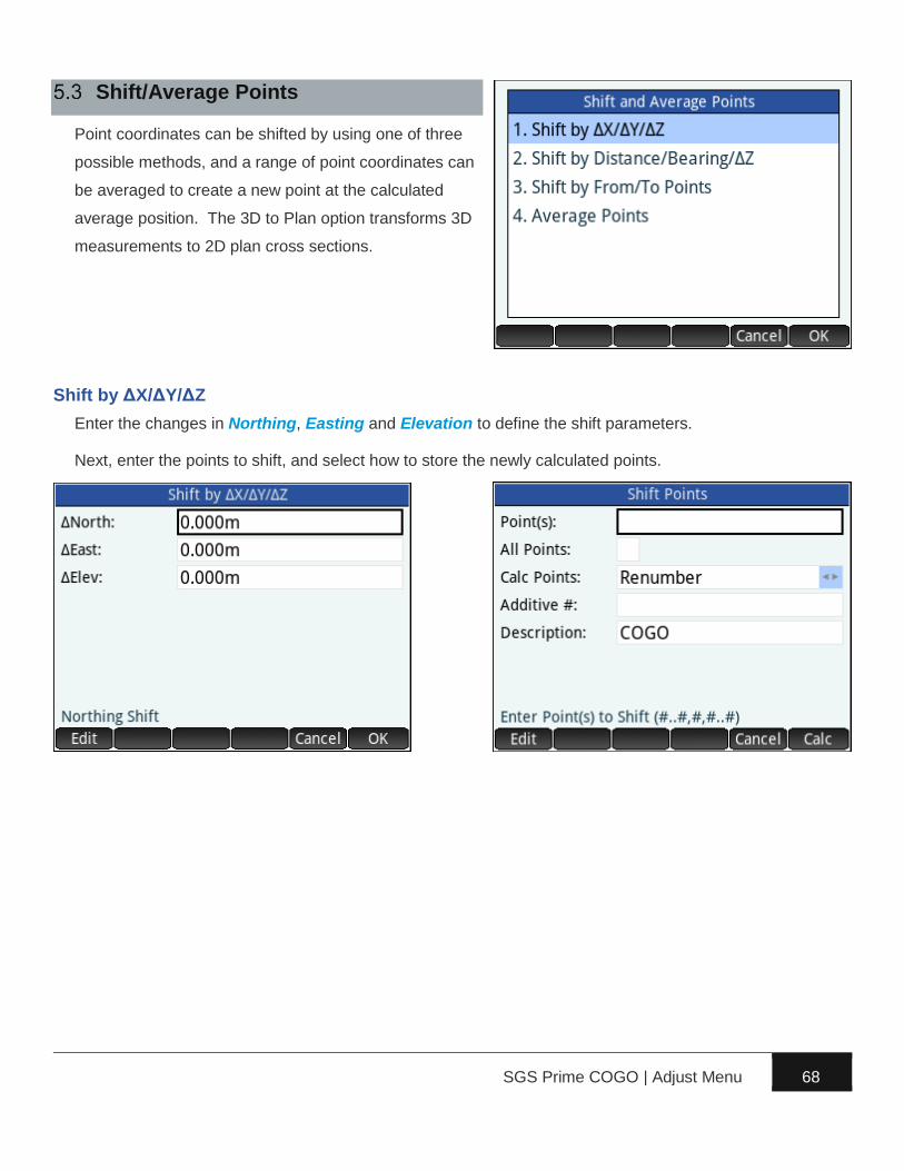
SGS Prime COGO | Adjust Menu 68
Shift/Average Points
Point coordinates can be shifted by using one of three
possible methods, and a range of point coordinates can
be averaged to create a new point at the calculated
average position. The 3D to Plan option transforms 3D
measurements to 2D plan cross sections.
Shift by ΔX/ΔY/ΔZ
Enter the changes in Northing, Easting and Elevation to define the shift parameters.
Next, enter the points to shift, and select how to store the newly calculated points.

SGS Prime COGO | Adjust Menu 69
Shift by Distance/Direction/ΔZ
Enter the horizontal Distance, the Azimuth or Bearing and the change in Elevation to define the shift
parameters. Use any of the standard distances and directions input options.
Next, enter the points to shift, and select how to store the newly calculated points.
Shift by From/To Points
Enter the From Point and To Point to allow the program to calculate the 3D shift parameters between
the two points.
Next, enter the points to shift, and select how to store the newly calculated points.

SGS Prime COGO | Adjust Menu 70
Average Points
Enter a series of points to compute their arithmetic
mean coordinate values. Point numbers can be entered
using any of the point numbers input options. At
minimum two points are required to calculate average
values.
The solution displays the calculated coordinates, their
standard deviation and the range in coordinate values.
The user is given the option to store the averaged point
in the project database.
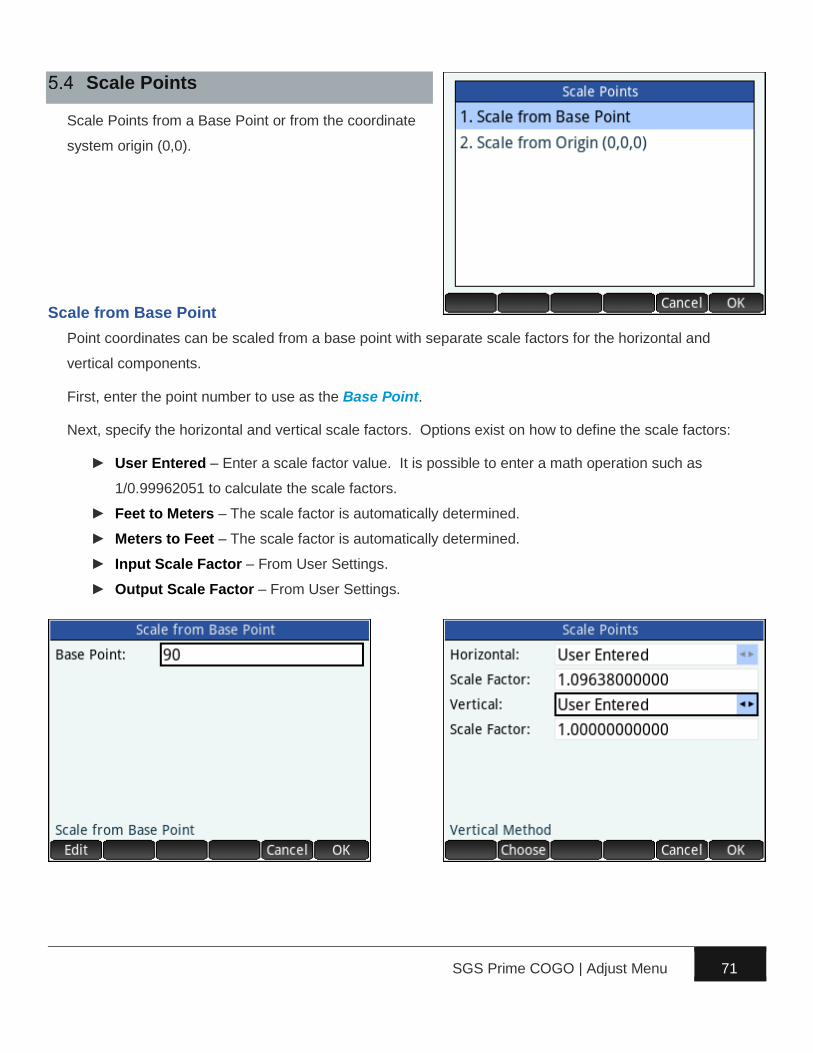
SGS Prime COGO | Adjust Menu 71
Scale Points
Scale Points from a Base Point or from the coordinate
system origin (0,0).
Scale from Base Point
Point coordinates can be scaled from a base point with separate scale factors for the horizontal and
vertical components.
First, enter the point number to use as the Base Point.
Next, specify the horizontal and vertical scale factors. Options exist on how to define the scale factors:
► User Entered – Enter a scale factor value. It is possible to enter a math operation such as
1/0.99962051 to calculate the scale factors.
► Feet to Meters – The scale factor is automatically determined.
► Meters to Feet – The scale factor is automatically determined.
► Input Scale Factor – From User Settings.
► Output Scale Factor – From User Settings.

SGS Prime COGO | Adjust Menu 72
Last, enter the points to scale, and select how to store the newly calculated points.
Scale from Origin (0,0,0)
Like Scale from Base Point, except no base point is required, the points will be scaled from 0,0,0.
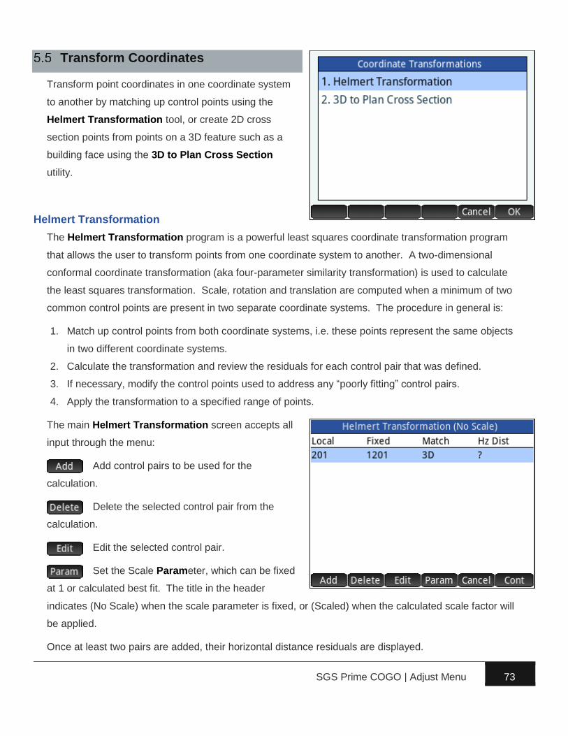
SGS Prime COGO | Adjust Menu 73
Transform Coordinates
Transform point coordinates in one coordinate system
to another by matching up control points using the
Helmert Transformation tool, or create 2D cross
section points from points on a 3D feature such as a
building face using the 3D to Plan Cross Section
utility.
Helmert Transformation
The Helmert Transformation program is a powerful least squares coordinate transformation program
that allows the user to transform points from one coordinate system to another. A two-dimensional
conformal coordinate transformation (aka four-parameter similarity transformation) is used to calculate
the least squares transformation. Scale, rotation and translation are computed when a minimum of two
common control points are present in two separate coordinate systems. The procedure in general is:
1. Match up control points from both coordinate systems, i.e. these points represent the same objects
in two different coordinate systems.
2. Calculate the transformation and review the residuals for each control pair that was defined.
3. If necessary, modify the control points used to address any “poorly fitting” control pairs.
4. Apply the transformation to a specified range of points.
The main Helmert Transformation screen accepts all
input through the menu:
Add control pairs to be used for the
calculation.
Delete the selected control pair from the
calculation.
Edit the selected control pair.
Set the Scale Parameter, which can be fixed
at 1 or calculated best fit. The title in the header
indicates (No Scale) when the scale parameter is fixed, or (Scaled) when the calculated scale factor will
be applied.
Once at least two pairs are added, their horizontal distance residuals are displayed.
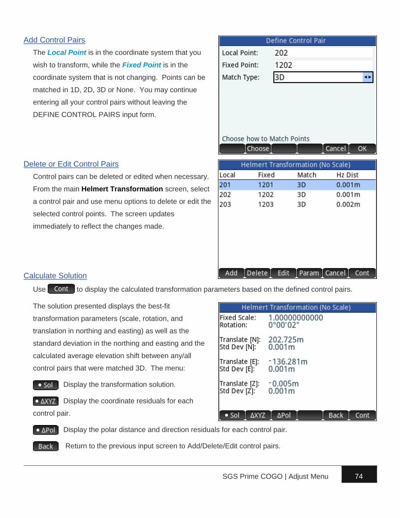
SGS Prime COGO | Adjust Menu 74
Add Control Pairs
The Local Point is in the coordinate system that you
wish to transform, while the Fixed Point is in the
coordinate system that is not changing. Points can be
matched in 1D, 2D, 3D or None. You may continue
entering all your control pairs without leaving the
DEFINE CONTROL PAIRS input form.
Delete or Edit Control Pairs
Control pairs can be deleted or edited when necessary.
From the main Helmert Transformation screen, select
a control pair and use menu options to delete or edit the
selected control points. The screen updates
immediately to reflect the changes made.
Calculate Solution
Use to display the calculated transformation parameters based on the defined control pairs.
The solution presented displays the best-fit
transformation parameters (scale, rotation, and
translation in northing and easting) as well as the
standard deviation in the northing and easting and the
calculated average elevation shift between any/all
control pairs that were matched 3D. The menu:
Display the transformation solution.
Display the coordinate residuals for each
control pair.
Display the polar distance and direction residuals for each control pair.
Return to the previous input screen to Add/Delete/Edit control pairs.

SGS Prime COGO | Adjust Menu 75
Examples of the residual screens:
Apply Transformation
Use when ready to apply the transformation.
Enter the points to transform, and select how to store
the newly calculated points.
Sample Coordinates
Point,Northing,Easting,Elevation,Description
201,5366358.241,470146.326,22.112,HT_LOCAL
202,5366207.625,470340.584,17.416,HT_LOCAL
203,5366043.182,470551.834,14.643,HT_LOCAL
204,5366215.676,470348.232,0.000,HT_LOCAL
205,5366290.117,470401.822,0.000,HT_LOCAL
206,5366123.497,470616.424,0.000,HT_LOCAL
207,5366048.800,470552.152,0.000,HT_LOCAL
1201,5366557.381,470050.977,22.107,HT_FIXED
1202,5366406.762,470245.234,17.411,HT_FIXED
1203,5366242.317,470456.485,14.639,HT_FIXED
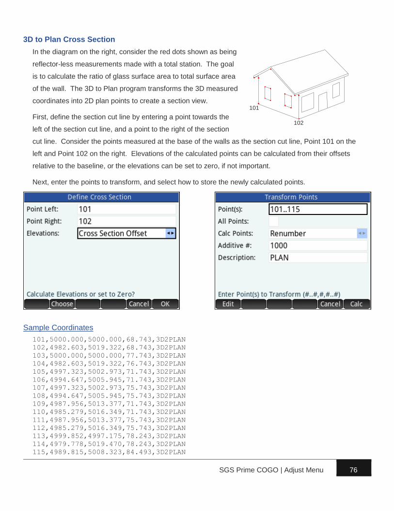
SGS Prime COGO | Adjust Menu 76
3D to Plan Cross Section
In the diagram on the right, consider the red dots shown as being
reflector-less measurements made with a total station. The goal
is to calculate the ratio of glass surface area to total surface area
of the wall. The 3D to Plan program transforms the 3D measured
coordinates into 2D plan points to create a section view.
First, define the section cut line by entering a point towards the
left of the section cut line, and a point to the right of the section
cut line. Consider the points measured at the base of the walls as the section cut line, Point 101 on the
left and Point 102 on the right. Elevations of the calculated points can be calculated from their offsets
relative to the baseline, or the elevations can be set to zero, if not important.
Next, enter the points to transform, and select how to store the newly calculated points.
Sample Coordinates
101,5000.000,5000.000,68.743,3D2PLAN
102,4982.603,5019.322,68.743,3D2PLAN
103,5000.000,5000.000,77.743,3D2PLAN
104,4982.603,5019.322,76.743,3D2PLAN
105,4997.323,5002.973,71.743,3D2PLAN
106,4994.647,5005.945,71.743,3D2PLAN
107,4997.323,5002.973,75.743,3D2PLAN
108,4994.647,5005.945,75.743,3D2PLAN
109,4987.956,5013.377,71.743,3D2PLAN
110,4985.279,5016.349,71.743,3D2PLAN
111,4987.956,5013.377,75.743,3D2PLAN
112,4985.279,5016.349,75.743,3D2PLAN
113,4999.852,4997.175,78.243,3D2PLAN
114,4979.778,5019.470,78.243,3D2PLAN
115,4989.815,5008.323,84.493,3D2PLAN
101
102
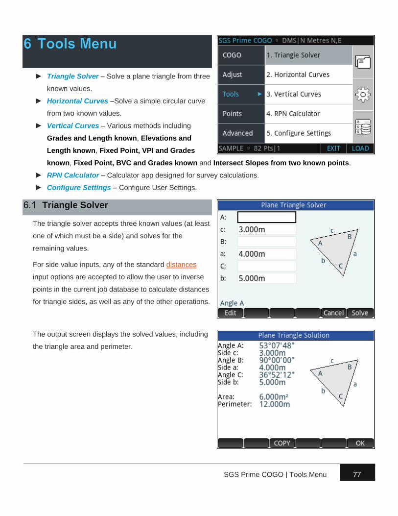
SGS Prime COGO | Tools Menu 77
► Triangle Solver – Solve a plane triangle from three
known values.
► Horizontal Curves –Solve a simple circular curve
from two known values.
► Vertical Curves – Various methods including
Grades and Length known, Elevations and
Length known, Fixed Point, VPI and Grades
known, Fixed Point, BVC and Grades known and Intersect Slopes from two known points.
► RPN Calculator – Calculator app designed for survey calculations.
► Configure Settings – Configure User Settings.
Triangle Solver
The triangle solver accepts three known values (at least
one of which must be a side) and solves for the
remaining values.
For side value inputs, any of the standard distances
input options are accepted to allow the user to inverse
points in the current job database to calculate distances
for triangle sides, as well as any of the other operations.
The output screen displays the solved values, including
the triangle area and perimeter.

SGS Prime COGO | Tools Menu 78
Horizontal Curves
Three options to solve horizontal curves:
1. Circular Curve Solver – Solve a simple circular
curve by entering two known elements.
2. Curve Through Fixed Point – Calculate the curve
that passes through a fixed point. Calculations are
possible when a point on the back tangent, at the
PI, on the forward tangent, and the fixed point are
provided.
3. Spiral Curve Solver – Solves all the Spiral-Curve-
Spiral parameters when entering a Spiral Length, a
total SCS deflection angle, and the curve radius.
Circular Curve Solver
The circular curve solver requires two known curve
elements and solves for the rest. Acceptable input
combinations include:
► The radius and any of the other accepted inputs.
► The deflection angle and any of the other accepted
inputs.
► The arc length and the chord length. NOTE: THIS
TYPE OF SOLUTION INVOKES THE ITERATIVE NEWTON’S
METHOD TO SOLVE FOR THE REMAINING VALUES. THE
RESULT ACCURACY DEPENDS ON THE INPUT
PRECISION.
Degree of Curve
A Deg of Curve button provides easy access to determine the radius of the curve by degree of curve,
both chord and arc definitions are available.
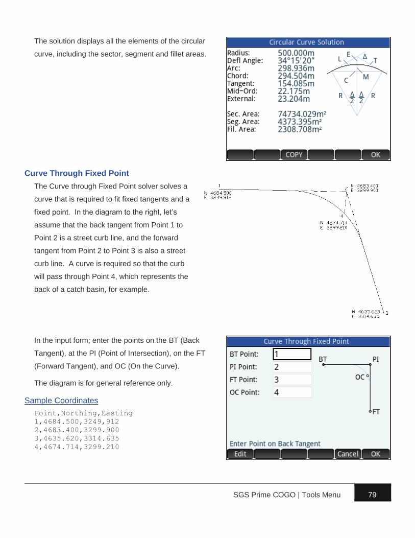
SGS Prime COGO | Tools Menu 79
The solution displays all the elements of the circular
curve, including the sector, segment and fillet areas.
Curve Through Fixed Point
The Curve through Fixed Point solver solves a
curve that is required to fit fixed tangents and a
fixed point. In the diagram to the right, let’s
assume that the back tangent from Point 1 to
Point 2 is a street curb line, and the forward
tangent from Point 2 to Point 3 is also a street
curb line. A curve is required so that the curb
will pass through Point 4, which represents the
back of a catch basin, for example.
In the input form; enter the points on the BT (Back
Tangent), at the PI (Point of Intersection), on the FT
(Forward Tangent), and OC (On the Curve).
The diagram is for general reference only.
Sample Coordinates
Point,Northing,Easting
1,4684.500,3249,912
2,4683.400,3299.900
3,4635.620,3314.635
4,4674.714,3299.210
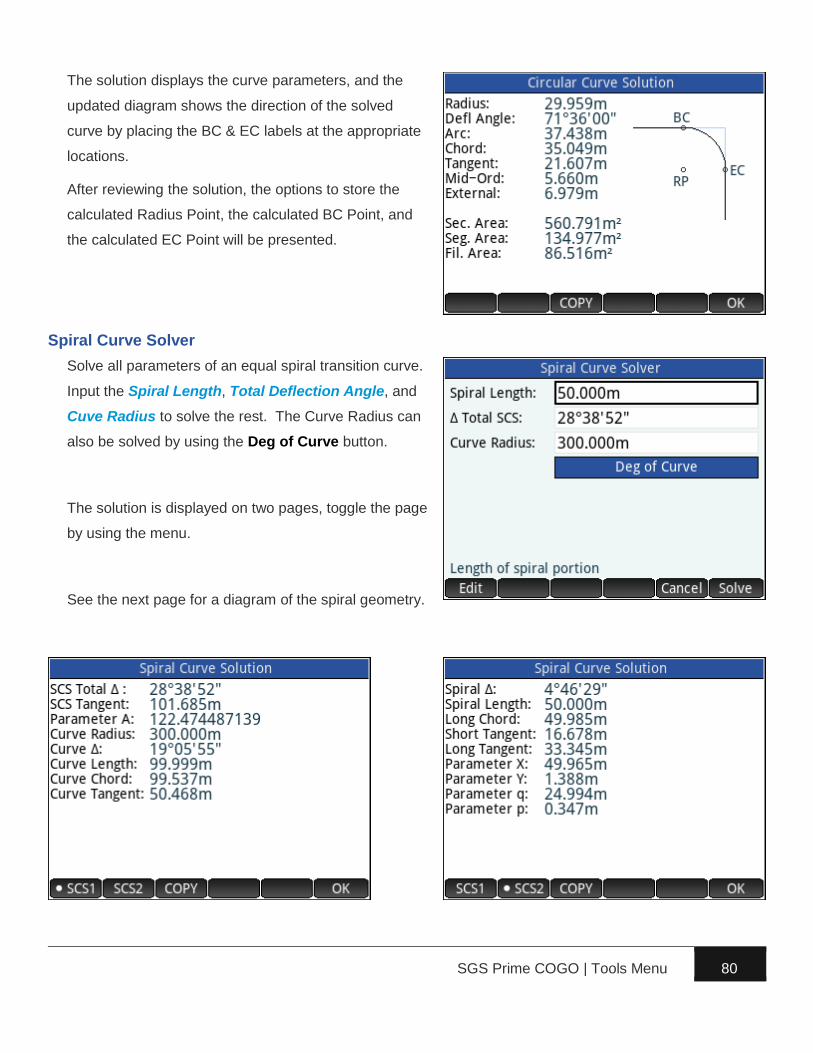
SGS Prime COGO | Tools Menu 80
The solution displays the curve parameters, and the
updated diagram shows the direction of the solved
curve by placing the BC & EC labels at the appropriate
locations.
After reviewing the solution, the options to store the
calculated Radius Point, the calculated BC Point, and
the calculated EC Point will be presented.
Spiral Curve Solver
Solve all parameters of an equal spiral transition curve.
Input the Spiral Length, Total Deflection Angle, and
Cuve Radius to solve the rest. The Curve Radius can
also be solved by using the Deg of Curve button.
The solution is displayed on two pages, toggle the page
by using the menu.
See the next page for a diagram of the spiral geometry.
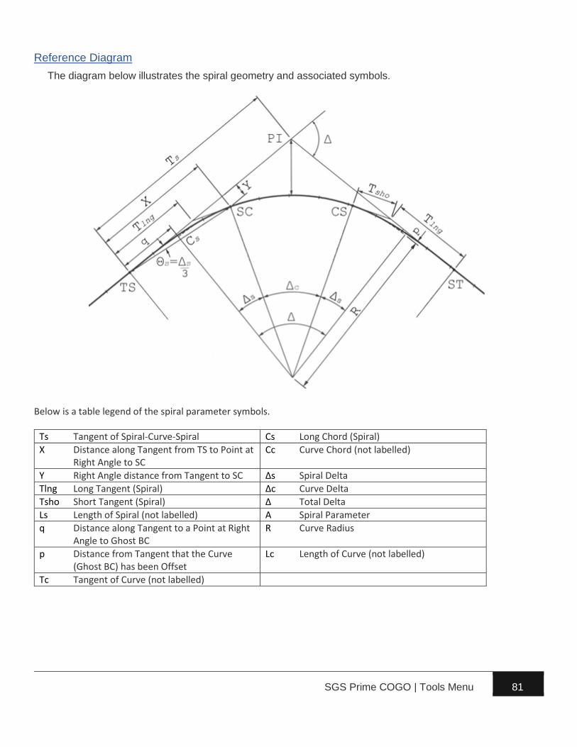
SGS Prime COGO | Tools Menu 81
Reference Diagram
The diagram below illustrates the spiral geometry and associated symbols.
Below is a table legend of the spiral parameter symbols.
Ts Tangent of Spiral-Curve-Spiral Cs Long Chord (Spiral)
X Distance along Tangent from TS to Point at Right Angle to SC
Cc Curve Chord (not labelled)
Y Right Angle distance from Tangent to SC Δs Spiral Delta
Tlng Long Tangent (Spiral) Δc Curve Delta
Tsho Short Tangent (Spiral) Δ Total Delta
Ls Length of Spiral (not labelled) A Spiral Parameter
q Distance along Tangent to a Point at Right Angle to Ghost BC
R Curve Radius
p Distance from Tangent that the Curve (Ghost BC) has been Offset
Lc Length of Curve (not labelled)
Tc Tangent of Curve (not labelled)

SGS Prime COGO | Tools Menu 82
Vertical Curves
The Vertical Curve Solver solves vertical curves using
various combinations of known parameters, including:
1. Grades and Length known – Requires a known
station at the BVC, VPI or EVC, the vertical curve
length, entry and exit grades, and a known
elevation at the BVC VPI, EVC or the High/Low
point on the curve.
2. Elevations and Length known – Requires a known
station at the BVC, VPI or EVC, the vertical curve length, and elevations at the BVC, VPI and EVC.
3. Fixed Point, VPI and Grades known – Requires the station and elevation at the VPI, a fixed point
station and elevation, entry and exit grades.
4. Fixed Point, BVC and Grades known – Requires the station and elevation at the BVC, a fixed point
station and elevation, entry and exit grades.
5. Intersect Slopes from two known points – Requires the vertical curve length, the entry grade, a
station with a known elevation on the entry tangent, the exit grade, and a station with a known
elevation on the exit tangent.
NOTE: BVC = Beginning of Vertical Curve, VPI = Vertical Point of Intersection, and EVC = End of
Vertical Curve.
The diagram below illustrates the vertical curve geometry.
VPI
BVC
EVC
Curve Length
Exit Tangent
Entry Tangent

SGS Prime COGO | Tools Menu 83
Grades and Length known
Enter all the required information to solve the curve.
► Choose the point on the vertical curve with a
known station (BVC, VPI or EVC)
► Enter the known station for the point
► Choose the point on the vertical curve with a
known elevation (BVC, VPI, EVC or the
High/Low Point)
► Enter the known elevation for the point
► Enter the vertical curve length
► Enter the entry grade
► Enter the exit grade
The solution displays the stations and elevations for
each the BVC, VPI, EVC and High/Low Point. See the
Solution Screen and Calculations section for more
information.
0+00.000
Elev=235.500m
100.000m

SGS Prime COGO | Tools Menu 84
Elevations and Length known
Enter all the required information to solve the curve.
► Choose the point on the vertical curve with a
known station (BVC, VPI or EVC)
► Enter the known station for the point
► Enter the vertical curve length
► Enter the BVC elevation
► Enter the VPI elevation
► Enter the EVC elevation
The solution displays the stations and elevations for
each the BVC, VPI, EVC and High/Low Point. See the
Solution Screen and Calculations section for more
information.
0+00.000
Elev=235.500m
100.000m
Elev=239.550m
Elev=238.750m

SGS Prime COGO | Tools Menu 85
Fixed Point, VPI and Grades known
Enter all the required information to solve the curve.
► Enter the VPI station
► Enter the VPI elevation
► Enter the fixed station
► Enter the elevation at the fixed station
► Enter the entry grade
► Enter the exit grade
The solution displays the stations and elevations for
each the BVC, VPI, EVC and High/Low Point. See the
Solution Screen and Calculations section for more
information.
0+50.000
0+20.000 Elev=238.222m
Elev=235.500m
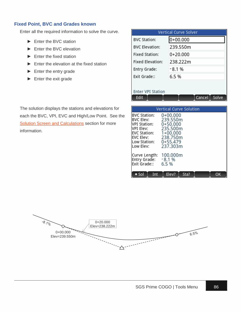
SGS Prime COGO | Tools Menu 86
Fixed Point, BVC and Grades known
Enter all the required information to solve the curve.
► Enter the BVC station
► Enter the BVC elevation
► Enter the fixed station
► Enter the elevation at the fixed station
► Enter the entry grade
► Enter the exit grade
The solution displays the stations and elevations for
each the BVC, VPI, EVC and High/Low Point. See the
Solution Screen and Calculations section for more
information.
0+00.000
0+20.000 Elev=238.222m
Elev=239.550m

SGS Prime COGO | Tools Menu 87
Intersect Slopes from two known points
Enter all the required information to solve the curve.
► Enter the curve length
► Enter the entry grade
► Enter a known station on the entry tangent
► Enter the elevation at the known station
► Enter the exit grade
► Enter a known station on the exit tangent
► Enter the elevation at the known station
The solution displays the stations and elevations for
each the BVC, VPI, EVC and High/Low Point. See the
Solution Screen and Calculations section for more
information.
0+10.000 Elev=238.740m
1+06.000 Elev=239.140m

SGS Prime COGO | Tools Menu 88
Solution Screen and Calculations
For each of the combinations of known parameters to
solve a vertical curve; the solution screen displays the
unknown solved parameters, and the menu on the
solution screen is the same for all combinations,
offering the same functionalities:
Calculate elevations at all stations at a given
interval.
Calculate elevations on the vertical curve by
entering a station.
Calculate stations on the vertical curve by entering an elevation.
Calculate Intervals
Enter a station interval to solve the elevations for each station at the given interval. The BVC and EVC
elevations are always solved, regardless of their station. Scroll down to see all the results if they do not
fit on one screen.
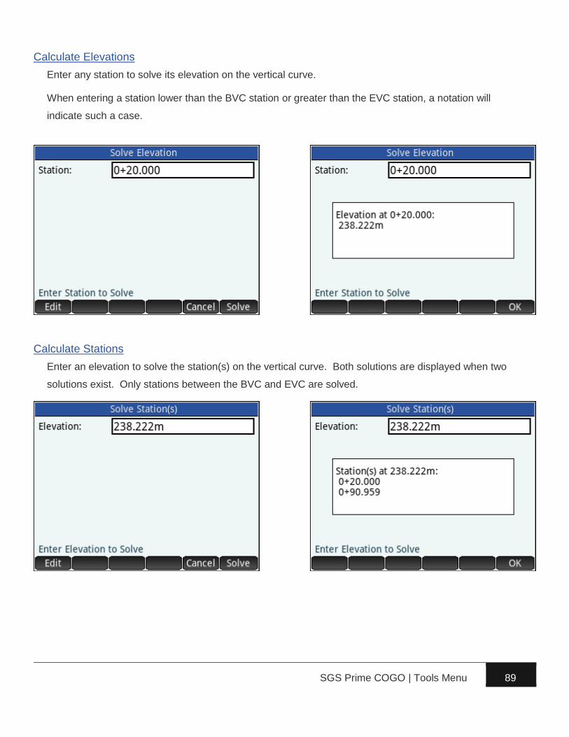
SGS Prime COGO | Tools Menu 89
Calculate Elevations
Enter any station to solve its elevation on the vertical curve.
When entering a station lower than the BVC station or greater than the EVC station, a notation will
indicate such a case.
Calculate Stations
Enter an elevation to solve the station(s) on the vertical curve. Both solutions are displayed when two
solutions exist. Only stations between the BVC and EVC are solved.

SGS Prime COGO | Tools Menu 90
RPN Calculator
The RPN Calculator is designed for survey calculations, with distance and angle unit support.
Main Interface
Use the touch screen to:
► Select an object on the stack
► Open the Edit Line
► Assign units to a stack selection, the edit line contents, or Level 1 of the stack
► Toggle the current menu (except when a stack selection is active, or the Edit Line is open)
► Execute a menu option
Keyboard keys have common functions assigned:
► E to DUP Level 1 of the stack
► L or R to SWAP Level 1 and 2 of the stack. Moves the cursor when the Edit Line is open.
► \ to DROP Level 1 of the stack. S and \ clears the stack.
► & to exit the application, cancel the Edit Line, or unselect a stack object.
► U or D to scroll through the stack. S and U or D jumps to the top or bottom level of
the stack. When no object is selected on the stack, D opens the Edit Line.
► S and + to UNDO the previous action. Only one level of UNDO is possible.
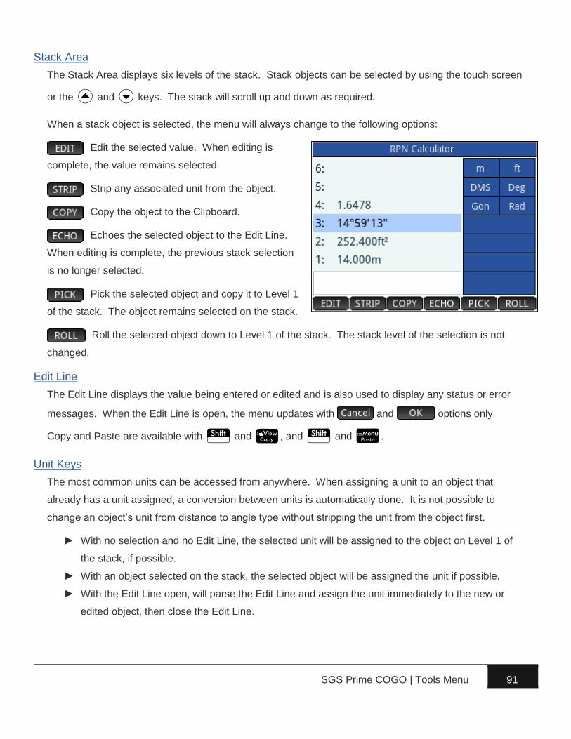
SGS Prime COGO | Tools Menu 91
Stack Area
The Stack Area displays six levels of the stack. Stack objects can be selected by using the touch screen
or the U and D keys. The stack will scroll up and down as required.
When a stack object is selected, the menu will always change to the following options:
Edit the selected value. When editing is
complete, the value remains selected.
Strip any associated unit from the object.
Copy the object to the Clipboard.
Echoes the selected object to the Edit Line.
When editing is complete, the previous stack selection
is no longer selected.
Pick the selected object and copy it to Level 1
of the stack. The object remains selected on the stack.
Roll the selected object down to Level 1 of the stack. The stack level of the selection is not
changed.
Edit Line
The Edit Line displays the value being entered or edited and is also used to display any status or error
messages. When the Edit Line is open, the menu updates with and options only.
Copy and Paste are available with S and V, and S and M.
Unit Keys
The most common units can be accessed from anywhere. When assigning a unit to an object that
already has a unit assigned, a conversion between units is automatically done. It is not possible to
change an object’s unit from distance to angle type without stripping the unit from the object first.
► With no selection and no Edit Line, the selected unit will be assigned to the object on Level 1 of
the stack, if possible.
► With an object selected on the stack, the selected object will be assigned the unit if possible.
► With the Edit Line open, will parse the Edit Line and assign the unit immediately to the new or
edited object, then close the Edit Line.

SGS Prime COGO | Tools Menu 92
Menu Toggles
Three different menus are available within the app when no Edit Line and no stack selection is active.
Stack Menu
DUPlicate Level 1 of the stack. {… 3 2 1} to {… 3 2 1 1}
SWAP Level 1 and Level 2 of the stack. {… 3 2 1} to {… 3 1 2}
DROP Level 1 of the stack. {… 3 2 1} to {… 3 2}
Copy OVER Level 2 and place it on Level 1 of the stack. {… 3 2 1} to {… 3 2 1 2}
ROTate the bottom three levels of the stack. {… 3 2 1} to {… 2 1 3}
UNROTate the bottom three levels of the stack. {… 3 2 1} to {… 1 3 2}
Units Menu
Area and volume units can be assigned to objects. Area units are automatically assigned when a
distance is multiplied by another distance, and volume units are automatically assigned when an area is
multiplied by a distance.
Available area and volume units include .
Tools Menu
Edit Level 1 of the stack.
Strip any associated unit from the object on Level 1 of the stack.
Copy the object on Level 1 of the stack to the Clipboard.
Paste the contents from the Clipboard into the Edit Line and open the Edit Line.
Convert polar coordinates to rectangular coordinates.
Requires a distance on Level 2 of the stack, and an angle on Level 1 of the stack. If no units are
assigned to either Level 1 or 2, then assumes current unit settings. The result is Latitude (delta North)
on Level 2 of the stack, and Departure (delta East) on Level 1 of the stack.
Convert rectangular coordinates to polar coordinates.
Requires a distance (delta North) on Level 2 of the stack, and a distance (delta East) on Level 1 of the
stack. If no units are assigned to either Level 1 or 2, then assumes both are the same unit, or when
neither value has a unit assigned, then assumes current program unit settings. The result is the
horizontal distance on Level 2 of the stack, and the angle from north on Level 1 of the stack.

SGS Prime COGO | Tools Menu 93
Configure Settings
See the User Settings chapter.

SGS Prime COGO | Points Menu 94
► Store and Edit Points – Store new points in the
current project database or edit the coordinates and
description of an existing point.
► Delete Points – Delete points from the current
project database.
► Renumber Points – Renumber a range of points
using a New Starting Number scheme or an
Additive Number scheme.
► Plot Points – Graphically display the points in the current project. Zoom and pan functionality is
available with all points in the current project, or a specified range of points.
► Import / Export – Import ASCII Points, Export ASCII Points and Export DXF Points.
Store and Edit Points
It is possible to store and edit points in the same input
form.
Point ID
Enter a Point ID to edit its coordinates or to store a new
point. The coordinate and description fields
automatically populate with existing coordinates and
description if the point exists.
Options while editing this field:
Search for the lowest unused point number in the job.
Search for the lowest unused point number starting from the current value.

SGS Prime COGO | Points Menu 95
Delete Points
Delete individual points, a range of points or all the
points from the current job. To delete individual points
or ranges of points, enter points using any of the point
numbers input options.
Check the All Points checkbox to delete all points.
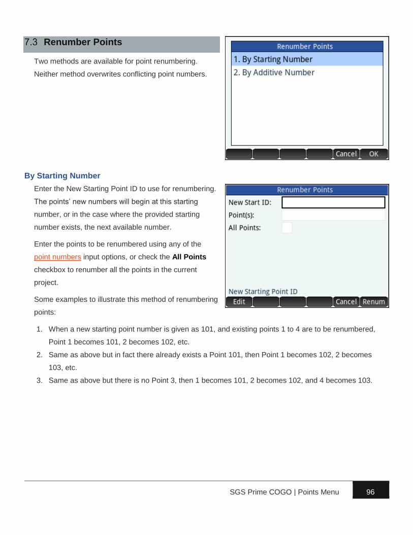
SGS Prime COGO | Points Menu 96
Renumber Points
Two methods are available for point renumbering.
Neither method overwrites conflicting point numbers.
By Starting Number
Enter the New Starting Point ID to use for renumbering.
The points’ new numbers will begin at this starting
number, or in the case where the provided starting
number exists, the next available number.
Enter the points to be renumbered using any of the
point numbers input options, or check the All Points
checkbox to renumber all the points in the current
project.
Some examples to illustrate this method of renumbering
points:
1. When a new starting point number is given as 101, and existing points 1 to 4 are to be renumbered,
Point 1 becomes 101, 2 becomes 102, etc.
2. Same as above but in fact there already exists a Point 101, then Point 1 becomes 102, 2 becomes
103, etc.
3. Same as above but there is no Point 3, then 1 becomes 101, 2 becomes 102, and 4 becomes 103.
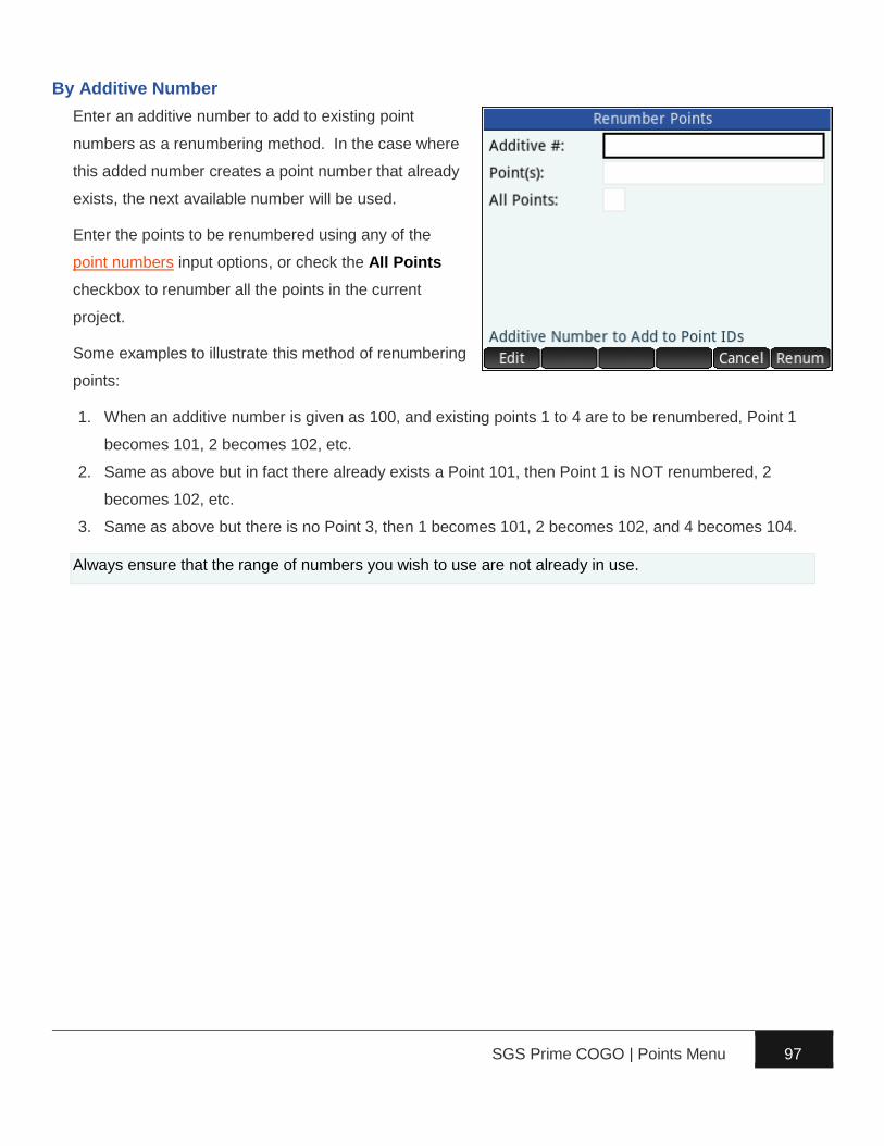
SGS Prime COGO | Points Menu 97
By Additive Number
Enter an additive number to add to existing point
numbers as a renumbering method. In the case where
this added number creates a point number that already
exists, the next available number will be used.
Enter the points to be renumbered using any of the
point numbers input options, or check the All Points
checkbox to renumber all the points in the current
project.
Some examples to illustrate this method of renumbering
points:
1. When an additive number is given as 100, and existing points 1 to 4 are to be renumbered, Point 1
becomes 101, 2 becomes 102, etc.
2. Same as above but in fact there already exists a Point 101, then Point 1 is NOT renumbered, 2
becomes 102, etc.
3. Same as above but there is no Point 3, then 1 becomes 101, 2 becomes 102, and 4 becomes 104.
Always ensure that the range of numbers you wish to use are not already in use.
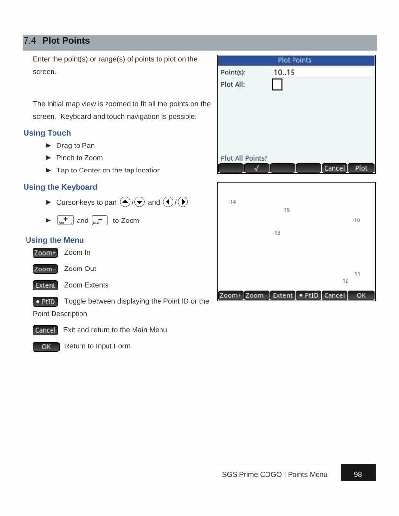
SGS Prime COGO | Points Menu 98
Plot Points
Enter the point(s) or range(s) of points to plot on the
screen.
The initial map view is zoomed to fit all the points on the
screen. Keyboard and touch navigation is possible.
Using Touch
► Drag to Pan
► Pinch to Zoom
► Tap to Center on the tap location
Using the Keyboard
► Cursor keys to pan U/D and L/R
► + and - to Zoom
Using the Menu
Zoom In
Zoom Out
Zoom Extents
Toggle between displaying the Point ID or the
Point Description
Exit and return to the Main Menu
Return to Input Form

SGS Prime COGO | Points Menu 99
Import/Export
Import and Export files containing Point data from/to the
App Files on the Prime calculator.
Import ASCII points
Import a delimited ASCII points file into the current
project database. The file must be present within the
App Files section of the SGS Prime COGO app and
must have one of the following extensions:
✓ .asc ASCii text file
✓ .csv Comma Separated Values
✓ .txt TeXT file
✓ .pts STAR*NET point coordinates
✓ .gnd STAR*NET ground coordinates
First, select the format and delimiter of the ASCII file
you wish to import. NOTE: THIS STEP IS CRITICAL TO ENSURE THAT THE DATA IS STORED CORRECTLY.
Select an ASCII file from the list to import.
The selected file is parsed line by line and the
coordinates are stored if valid data is found. Point
number conflicts result in a screen showing the
coordinate differences and YES/NO/YES TO ALL/NO
TO ALL options to overwrite the existing point(s). The
import progress is displayed while the file is processed,
and the total number of points added or modified in the
project database is reported when import is completed.
During Import, lines starting with the # character are ignored.
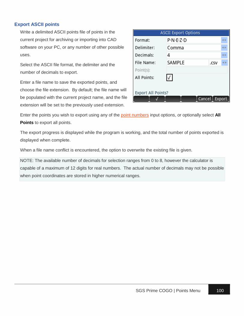
SGS Prime COGO | Points Menu 100
Export ASCII points
Write a delimited ASCII points file of points in the
current project for archiving or importing into CAD
software on your PC, or any number of other possible
uses.
Select the ASCII file format, the delimiter and the
number of decimals to export.
Enter a file name to save the exported points, and
choose the file extension. By default; the file name will
be populated with the current project name, and the file
extension will be set to the previously used extension.
Enter the points you wish to export using any of the point numbers input options, or optionally select All
Points to export all points.
The export progress is displayed while the program is working, and the total number of points exported is
displayed when complete.
When a file name conflict is encountered, the option to overwrite the existing file is given.
NOTE: The available number of decimals for selection ranges from 0 to 8, however the calculator is
capable of a maximum of 12 digits for real numbers. The actual number of decimals may not be possible
when point coordinates are stored in higher numerical ranges.

SGS Prime COGO | Points Menu 101
Export DXF Points
Write a DXF file (ASCII format) of points in the current
project to open with CAD software on your PC.
Select the items to export. Point nodes are always
exported, but the text attributes of the points are
optional.
Specify the text height for the text attributes. By default,
for metric projects the text height will be suggested as
1.0, and for imperial projects the text height will be
suggested as 3.0.
Enter a file name to save the exported points. By default; the file name will be populated with the current
project name.
Enter the points you wish to export using any of the point numbers input options, or optionally select All
Points to export all points.
The export progress is displayed while the program is working, and the total number of points exported is
displayed when complete.
When a file name conflict is encountered, the option to overwrite the existing file is given.
The point node and text entities will be created using the DXF File Layers settings.

SGS Prime COGO | Advanced Menu 102
SGS Prime COGO Version 1.x is only available in Lite
or Standard editions. The Advanced Menu features will
be available in a future release as a Professional
edition.
While the timeline for completion is not precisely known,
the demand for these features will have an impact on
completion time. Please email [email protected] if you
are interested in these features, or possibly other similar features.
The final functionality may differ from the proposed list of features.
Alignments
Full 3D road alignments similar to the COGO+ Pro feature available for HP 50g.
Additional functionality is planned, including LandXML Import and Export.
Leveling
Leveling program similar to the COGO+ Pro feature available for HP 50g.
Traverse Plus 3D
Survey measurement computations similar to Traverse Plus feature available in COGO+ Pro for HP50g.
Coordinate Converter
Conversion between grid and geodetic coordinates similar to COGO+ Pro for HP50g.
Additional functionality planned, including conversions between different projections, and support for
transformation parameters.
Ellipsoid Calculations
DIRECT and INVERSE computations on the ellipsoid similar to COGO+ Pro for HP 50g.
![Building Professionals Board v Cogo [2009] NSWADT 10bpb.nsw.gov.au/sites/default/files/public/Disciplinary actions... · Building Professionals Board v Cogo [2009] ... and the history](https://static.fdocuments.in/doc/165x107/5aa43f4c7f8b9a185d8bbe09/building-professionals-board-v-cogo-2009-nswadt-10bpbnswgovausitesdefaultfilespublicdisciplinary.jpg)