SEWERAGE AND SANITARY WORKS -...
56
CODE OF PRACTICE ON SEWERAGE AND SANITARY WORKS 1 st Edition - Mar 2000 Addendum No. 1 -Feb 2001 Addendum No. 2 – Nov 2004 Water Reclamation (Network) Department Singapore (This Code of Practice is published on the PUB Website at URL Address http://www.pub.gov.sg)
Transcript of SEWERAGE AND SANITARY WORKS -...
CODE OF PRACTICE
ON
SEWERAGE AND SANITARY WORKS
1st Edition
- Mar 2000
Addendum No. 1
-Feb 2001
Addendum No. 2
– Nov 2004
Water Reclamation (Network) Department
Singapore
(This Code of Practice is published on the PUB Website
at URL Address http://www.pub.gov.sg)
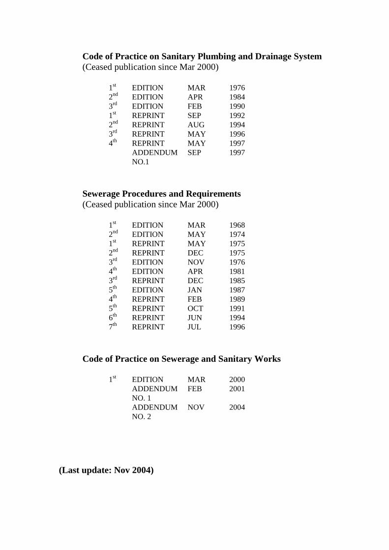
Code of Practice on Sanitary Plumbing and Drainage System
(Ceased publication since Mar 2000)
1
st EDITION MAR 1976
2nd
EDITION APR 1984
3rd
EDITION FEB 1990
1st REPRINT SEP 1992
2nd
REPRINT AUG 1994
3rd
REPRINT MAY 1996
4th
REPRINT MAY 1997
ADDENDUM
NO.1
SEP 1997
Sewerage Procedures and Requirements
(Ceased publication since Mar 2000)
1
st EDITION MAR 1968
2nd
EDITION MAY 1974
1st REPRINT MAY 1975
2nd
REPRINT DEC 1975
3rd
EDITION NOV 1976
4th
EDITION APR 1981
3rd
REPRINT DEC 1985
5th
EDITION JAN 1987
4th
REPRINT FEB 1989
5th
REPRINT OCT 1991
6th
REPRINT JUN 1994
7th
REPRINT JUL 1996
Code of Practice on Sewerage and Sanitary Works
1
st EDITION MAR 2000
ADDENDUM
NO. 1
FEB 2001
ADDENDUM
NO. 2
NOV 2004
(Last update: Nov 2004)
CODE OF PRACTICE
ON
SEWERAGE AND SANITARY WORKS
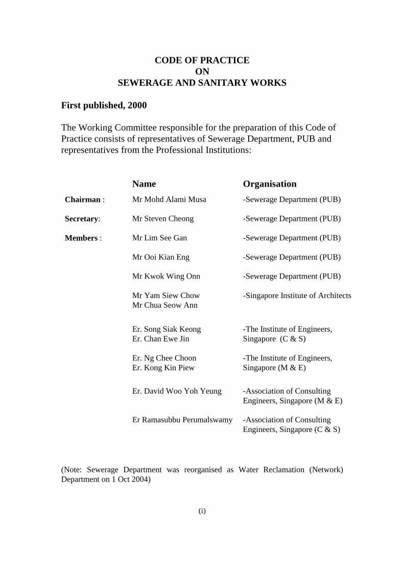
First published, 2000
The Working Committee responsible for the preparation of this Code of
Practice consists of representatives of Sewerage Department, PUB and
representatives from the Professional Institutions:
Name Organisation
Chairman : Mr Mohd Alami Musa -Sewerage Department (PUB)
Secretary: Mr Steven Cheong
-Sewerage Department (PUB)
Members : Mr Lim See Gan -Sewerage Department (PUB)
Mr Ooi Kian Eng -Sewerage Department (PUB)
Mr Kwok Wing Onn -Sewerage Department (PUB)
Mr Yam Siew Chow
Mr Chua Seow Ann
-Singapore Institute of Architects
Er. Song Siak Keong
Er. Chan Ewe Jin
-The Institute of Engineers,
Singapore (C & S)
Er. Ng Chee Choon
Er. Kong Kin Piew
-The Institute of Engineers,
Singapore (M & E)
Er. David Woo Yoh Yeung
-Association of Consulting
Engineers, Singapore (M & E)
Er Ramasubbu Perumalswamy -Association of Consulting
Engineers, Singapore (C & S)
(Note: Sewerage Department was reorganised as Water Reclamation (Network)
Department on 1 Oct 2004)
(i)
CODE OF PRACTICE
ON
SEWERAGE AND SANITARY WORKS
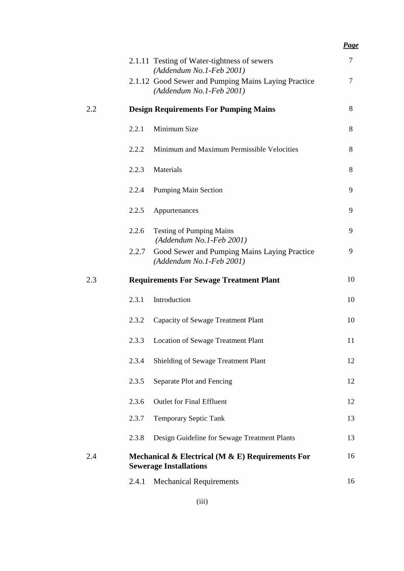
CONTENTS
Page
Introduction (vi)
Terminology (vii)
PART 1 PLANNING & DESIGN REQUIREMENTS
FOR DEVELOPMENT WORKS
1
1.1 Introduction 1
1.2 Planning Requirements 1
PART 2 SEWERAGE WORKS 4
2.1 Design Requirements For Sewers 4
2.1.1 Objective 4
2.1.2 Design Flow 4
2.1.3 Size 4
2.1.4 Permissible Velocities and Grades 4
2.1.5 Materials 5
2.1.6 Sewer Sections 5
2.1.7 Sewer manholes 5
2.1.8 Other Appurtenances 6
2.1.9 Sewer Joints and Connections 6
2.1.10 Sewer Pipe Jacking Operations 7
(ii)
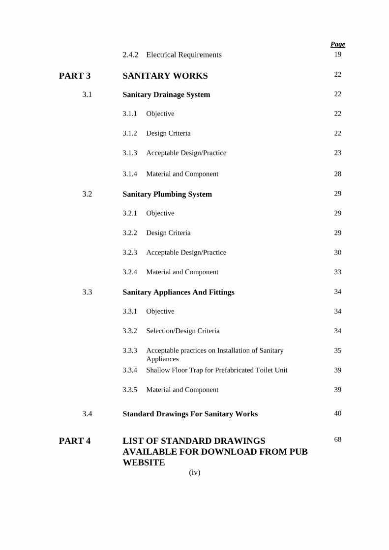
Page
2.1.11 Testing of Water-tightness of sewers
(Addendum No.1-Feb 2001)
7
2.1.12 Good Sewer and Pumping Mains Laying Practice
(Addendum No.1-Feb 2001)
7
2.2 Design Requirements For Pumping Mains 8
2.2.1 Minimum Size 8
2.2.2 Minimum and Maximum Permissible Velocities 8
2.2.3 Materials 8
2.2.4 Pumping Main Section 9
2.2.5 Appurtenances 9
2.2.6 Testing of Pumping Mains
(Addendum No.1-Feb 2001)
9
2.2.7 Good Sewer and Pumping Mains Laying Practice
(Addendum No.1-Feb 2001)
9
2.3 Requirements For Sewage Treatment Plant 10
2.3.1 Introduction 10
2.3.2 Capacity of Sewage Treatment Plant 10
2.3.3 Location of Sewage Treatment Plant 11
2.3.4 Shielding of Sewage Treatment Plant 12
2.3.5 Separate Plot and Fencing 12
2.3.6 Outlet for Final Effluent 12
2.3.7 Temporary Septic Tank 13
2.3.8 Design Guideline for Sewage Treatment Plants 13
2.4 Mechanical & Electrical (M & E) Requirements For
Sewerage Installations
16
2.4.1 Mechanical Requirements 16
(iii)
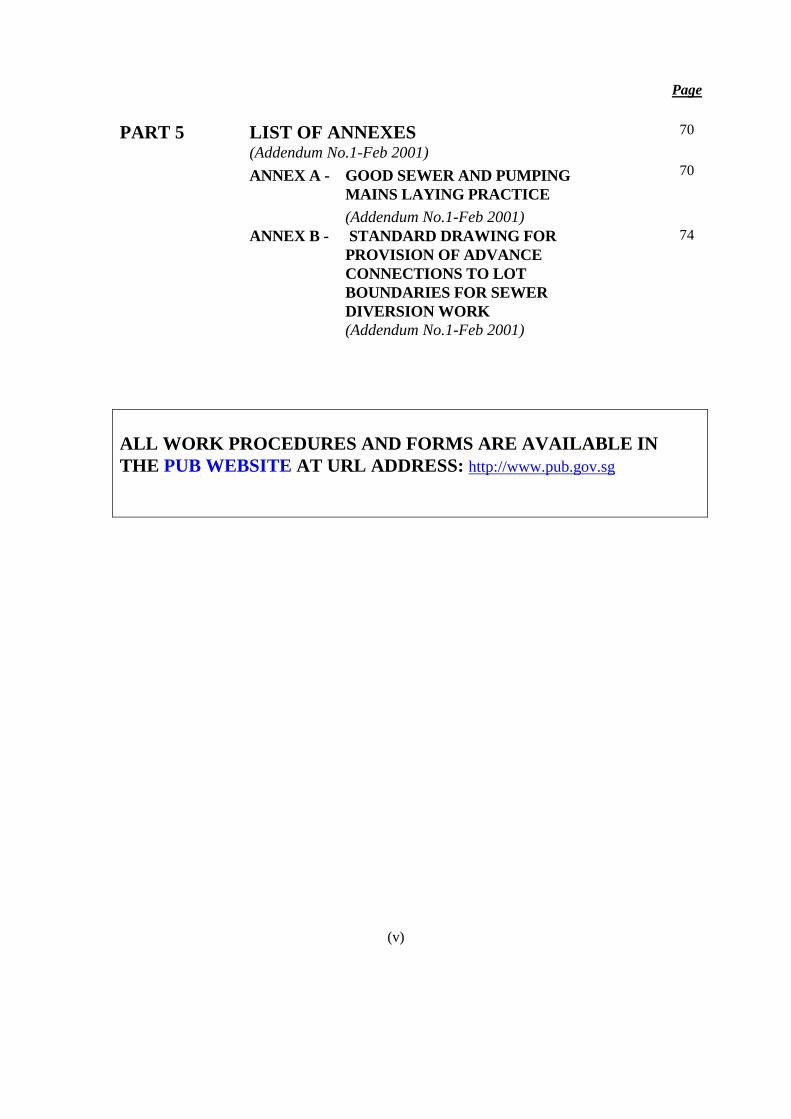
Page
2.4.2 Electrical Requirements 19
PART 3 SANITARY WORKS 22
3.1 Sanitary Drainage System 22
3.1.1 Objective 22
3.1.2 Design Criteria 22
3.1.3 Acceptable Design/Practice 23
3.1.4 Material and Component 28
3.2 Sanitary Plumbing System 29
3.2.1 Objective 29
3.2.2 Design Criteria 29
3.2.3 Acceptable Design/Practice 30
3.2.4 Material and Component 33
3.3 Sanitary Appliances And Fittings 34
3.3.1 Objective 34
3.3.2 Selection/Design Criteria 34
3.3.3 Acceptable practices on Installation of Sanitary
Appliances
35
3.3.4 Shallow Floor Trap for Prefabricated Toilet Unit 39
3.3.5 Material and Component 39
3.4 Standard Drawings For Sanitary Works 40
PART 4 LIST OF STANDARD DRAWINGS
AVAILABLE FOR DOWNLOAD FROM PUB
WEBSITE
68
(iv)
Page
PART 5 LIST OF ANNEXES (Addendum No.1-Feb 2001)
70
ANNEX A - GOOD SEWER AND PUMPING
MAINS LAYING PRACTICE
(Addendum No.1-Feb 2001)
70
ANNEX B - STANDARD DRAWING FOR
PROVISION OF ADVANCE
CONNECTIONS TO LOT
BOUNDARIES FOR SEWER
DIVERSION WORK
(Addendum No.1-Feb 2001)
74
ALL WORK PROCEDURES AND FORMS ARE AVAILABLE IN
THE PUB WEBSITE AT URL ADDRESS: http://www.pub.gov.sg
(v)
INTRODUCTION
Singapore is characterised by abundant rainfall, high temperature and
humidity. Coupled with high population density, waterborne diseases can spread
easily and quickly unless a high standard of public health is maintained. Proper
collection, treatment and disposal of domestic and industrial wastewater is therefore
necessary to prevent the pollution of watercourses, reservoirs, rivers and the sea, and
thus, the spread of diseases.
In Singapore, domestic and industrial wastewater is collected and conveyed by
sewers to sewage treatment works for treatment before final discharge into the sea.
Hence, it is essential that adequate care and precaution be taken to ensure that new
development works do not affect the existing sewerage system. It is also important
that the sanitary and sewerage system that are to be provided to serve new
developments are designed and constructed properly to maintain the effectiveness of
the entire sewerage system.
This Code of Practice on Sewerage and Sanitary Works is issued under
Section 33 of the Sewerage and Drainage Act (Chapter 294). It aims to guide the
Qualified Persons in the proper planning and design of the sanitary and sewerage
system. In stipulating only the minimum and mandatory design requirements to be
complied with, it is hoped that the Qualified Persons will exercise flexibility and
creativity in the design of sanitary and sewerage system without compromising on
functional and maintenance needs. In addition to the minimum requirements, some
good engineering practices in the planning, design and construction of the sanitary and
sewerage system are also given in this code.
Director
Water Reclamation (Network) Department
Public Utilities Board
Singapore
(vi)
TERMINOLOGY
“Central Building Plan
Unit (CBPU)”
refers to the Central Building Plan Unit of the Planning and
Development Department, National Environment Agency
(NEA);
“Department” refers to the Water Reclamation (Network) Department
(WRN) of the Public Utilities Board (PUB);
(Addendum No.2-Nov 2004)
“discharge pipe” means a pipe which conveys the discharges from a sanitary
appliance or a floor trap;
“discharge stack” means a main vertical discharge pipe;
“drain-line” means any pipe which is connected to the sewerage system;
“fittings” means any apparatus or parts used for any sanitary facility or
drain-line of any premises;
“public sewerage system” includes-
(a) sewerage system which were vested in the Government
before the appointed day under the repealed Water
Pollution Control and Drainage Act (Cap. 348) or any
other written law;
(b) sewerage systems with respect to which a declaration of
vesting has been made under Section 9 of the Sewerage
and Drainage Act;
(c) sewerage systems constructed by the Government or the
Public Utilities Board on behalf of the Government on any
private property at the expense of the Government or
acquired by the Government; and
(d) sewerage systems constructed on any private property and
maintained by the Public Utilities Board;
“public sewer” includes-
(a) sewers which were vested in the Government before the
appointed day under the repealed Water Pollution Control
and Drainage Act (Cap. 348) or any other written law;
(b) sewers with respect to which a declaration of vesting has
been made under Section 10 of the Sewerage and Drainage
Act;
(c) sewers constructed by the Government or the Public
Utilities Board on behalf of the Government on any private
property at the expense of the Government or acquired by
the Government; and
(d) sewers constructed on any private property and maintained
by the Public Utilities Board;
“qualified person” in relation to any sewerage works, means a qualified person
appointed under section 6(3) or 9(2)(b) of the Building Control
Act (Cap. 29) in respect of works which include the sewerage
works, and those whose qualification is appropriate to the
nature of those works;
(vii)
“sanitary appliances” includes wash basins, bath tubs, sinks, urinals, toilet bowls and
other appliances which connect, directly or otherwise, to a
private sewage treatment plant or a public sewerage system;
“sanitary drainage
system”
means a network of underground pipes comprising drain-lines,
branch drain-lines, fittings and inspection chambers for the
conveyance of sewage within any premises to a sewerage
system;
“sanitary facilities” includes bathrooms, toilets, facilities for washing and sanitary
appliances, together with the associated pipe-work, whether
above or below the ground, which connect, directly or
otherwise, to a private sewage treatment or a public sewerage
system;
“sanitary plumbing
system”
means a system of sanitary pipework above the ground
comprising one or more discharge pipes, discharge stacks,
ventilating pipes, ventilating stacks and fittings for the
conveyance of sewage from premises to a sanitary drainage
system;
“sanitary works” include works on any sanitary plumbing system or sanitary
drainage system and the fixing, alteration and repair of a
sanitary appliance, and other works connected therewith;
“septic tank” means a tank through which sewage flows and the deposited
organic matter is wholly, or partially broken down
anaerobically;
“sewage” includes water-borne domestic waste and trade effluent;
“sewage treatment plant” refers to sewage treatment works, septic tank, imhoff tank,
percolating filter, sludge digestion tank, or any tank designed
for the pretreatment, treatment or the stabilisation of sewage
“sewerage system” means a system of sewers, pumping mains, pumping stations,
sewage treatment plants and treatment works for the
collection, treatment and disposal of sewage and recovery of
industrial water and includes any industrial water main and
pipe, drain-line, grease trap, cesspit, septic tank, privy and any
appurtenance thereof;
“sewerage works” includes engineering works for the construction, alteration and
maintenance of any sewerage system;
“ventilating pipe” means a pipe provided to limit the pressure fluctuations within
any sanitary plumbing system;
“ventilating stack” means a main vertical ventilating pipe.
(viii)
Code of Practice on Sewerage and Sanitary Works (1st Edition – Mar 2000) (Updated: Nov 2004)
1
PART 1
PLANNING & DESIGN REQUIREMENTS
FOR DEVELOPMENT WORKS
1.1 INTRODUCTION
It is essential that adequate measures are taken during the planning, design and
construction of all new building and infrastructure developments to ensure that they do
not affect or undermine the integrity of the existing sewerage system. It is also important
that good design and engineering practices are adopted in the planning, design and
construction of new sanitary drain-lines and sewers to ensure that they can perform
effectively and with minimal maintenance.
1.2 PLANNING REQUIREMENTS
1.2.1 All new developments shall be served by an internal sanitary plumbing and drainage
system. This internal sanitary plumbing and drainage system shall be connected to public
sewers by an internal drain-line maintained by the owner or occupier of the development.
In the planning and design of the internal drain-line and its connection to the public
sewers, the following requirements shall be complied with:
(a) A development shall make use of the existing sewer connection that is located within
the development site. If an existing connection is not available, the connection shall
be made to the nearest public sewer as advised by the Department.
(b) For high density housing developments, such as condominiums and apartments, the
internal drain-lines shall be connected to the public sewers via manholes.
(c) For single unit housing development, the drain-line connection can be made to the
public sewers via raised junction or ‘Y’ junction connections. In this case, the last
inspection chamber within the development site shall be located not more than 2.5m
away from the development boundary.
(d) Where a new minor sewer is laid to pick up flow from the drain-lines from a row of
single unit housing development, the new sewer can also be connected to the public
sewer via raised junction or ‘Y’ junction connections, subject to the following
criteria:
(i) the last manhole that is located within the last housing unit shall not be more
than 50m away from the point of connection.
(ii) the connecting sewer from the last manhole to the existing sewer shall
follow the size of the existing sewer, or 200mm diameter, whichever is
smaller. The new minor sewer upstream of the last manhole shall,
however, remain at the minimum size of 200mm diameter. (Note: For
connection to an existing sewer via a manhole, the connection sewer from
the last manhole shall also be 200mm diameter. This is regardless of the
size of the existing sewer).
Code of Practice on Sewerage and Sanitary Works (1st Edition – Mar 2000) (Updated: Nov 2004)
2
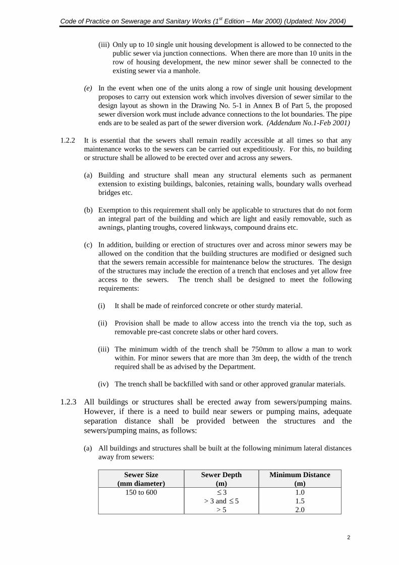
(iii) Only up to 10 single unit housing development is allowed to be connected to the
public sewer via junction connections. When there are more than 10 units in the
row of housing development, the new minor sewer shall be connected to the
existing sewer via a manhole.
(e) In the event when one of the units along a row of single unit housing development
proposes to carry out extension work which involves diversion of sewer similar to the
design layout as shown in the Drawing No. 5-1 in Annex B of Part 5, the proposed
sewer diversion work must include advance connections to the lot boundaries. The pipe
ends are to be sealed as part of the sewer diversion work. (Addendum No.1-Feb 2001)
1.2.2 It is essential that the sewers shall remain readily accessible at all times so that any
maintenance works to the sewers can be carried out expeditiously. For this, no building
or structure shall be allowed to be erected over and across any sewers.
(a) Building and structure shall mean any structural elements such as permanent
extension to existing buildings, balconies, retaining walls, boundary walls overhead
bridges etc.
(b) Exemption to this requirement shall only be applicable to structures that do not form
an integral part of the building and which are light and easily removable, such as
awnings, planting troughs, covered linkways, compound drains etc.
(c) In addition, building or erection of structures over and across minor sewers may be
allowed on the condition that the building structures are modified or designed such
that the sewers remain accessible for maintenance below the structures. The design
of the structures may include the erection of a trench that encloses and yet allow free
access to the sewers. The trench shall be designed to meet the following
requirements:
(i) It shall be made of reinforced concrete or other sturdy material.
(ii) Provision shall be made to allow access into the trench via the top, such as
removable pre-cast concrete slabs or other hard covers.
(iii) The minimum width of the trench shall be 750mm to allow a man to work
within. For minor sewers that are more than 3m deep, the width of the trench
required shall be as advised by the Department.
(iv) The trench shall be backfilled with sand or other approved granular materials.
1.2.3 All buildings or structures shall be erected away from sewers/pumping mains.
However, if there is a need to build near sewers or pumping mains, adequate
separation distance shall be provided between the structures and the
sewers/pumping mains, as follows:
(a) All buildings and structures shall be built at the following minimum lateral distances
away from sewers:
Sewer Size
(mm diameter)
Sewer Depth
(m)
Minimum Distance
(m)
150 to 600 3
> 3 and 5
> 5
1.0
1.5
2.0
Code of Practice on Sewerage and Sanitary Works (1st Edition – Mar 2000) (Updated: Nov 2004)
3
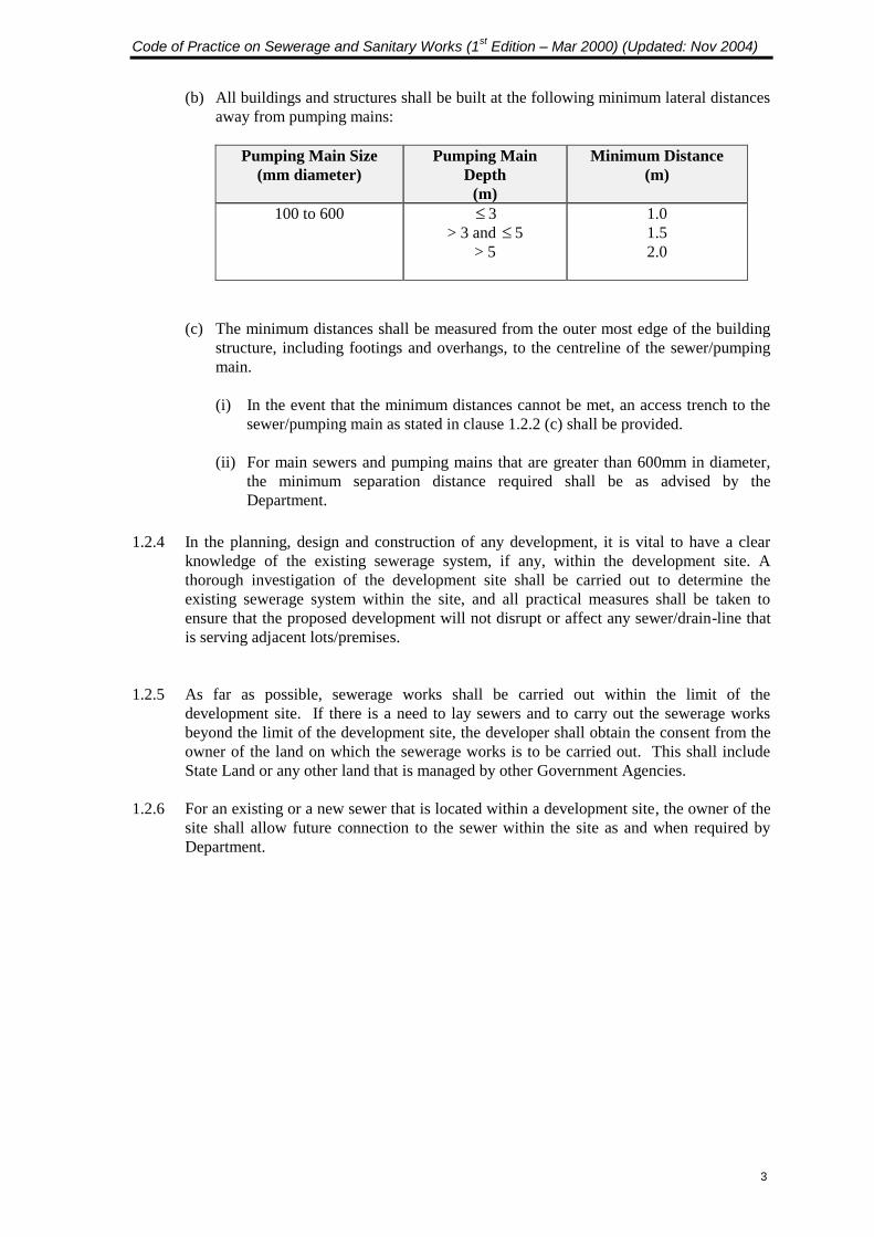
(b) All buildings and structures shall be built at the following minimum lateral distances
away from pumping mains:
Pumping Main Size
(mm diameter)
Pumping Main
Depth
(m)
Minimum Distance
(m)
100 to 600
3
> 3 and 5
> 5
1.0
1.5
2.0
(c) The minimum distances shall be measured from the outer most edge of the building
structure, including footings and overhangs, to the centreline of the sewer/pumping
main.
(i) In the event that the minimum distances cannot be met, an access trench to the
sewer/pumping main as stated in clause 1.2.2 (c) shall be provided.
(ii) For main sewers and pumping mains that are greater than 600mm in diameter,
the minimum separation distance required shall be as advised by the
Department.
1.2.4 In the planning, design and construction of any development, it is vital to have a clear
knowledge of the existing sewerage system, if any, within the development site. A
thorough investigation of the development site shall be carried out to determine the
existing sewerage system within the site, and all practical measures shall be taken to
ensure that the proposed development will not disrupt or affect any sewer/drain-line that
is serving adjacent lots/premises.
1.2.5 As far as possible, sewerage works shall be carried out within the limit of the
development site. If there is a need to lay sewers and to carry out the sewerage works
beyond the limit of the development site, the developer shall obtain the consent from the
owner of the land on which the sewerage works is to be carried out. This shall include
State Land or any other land that is managed by other Government Agencies.
1.2.6 For an existing or a new sewer that is located within a development site, the owner of the
site shall allow future connection to the sewer within the site as and when required by
Department.

Code of Practice on Sewerage and Sanitary Works (1st Edition – Mar 2000) (Updated: Nov 2004)
4
PART 2
SEWERAGE WORKS
2.1 DESIGN REQUIREMENTS FOR SEWERS
2.1.1 Objective
Sewers shall be planned and designed to be as simple and as direct as practicable for
effectual conveyance of sewage. They shall also be laid at the correct grade using
approved materials to ensure minimal maintenance requirement and maximum durability.
2.1.2 Design Flow
The design flow is based on the amount of sewage discharged per person. The average
domestic sewage daily flow shall be taken as 230 litres per person per day for public
housing and 345 litres per person per day for private housing. The design flow shall be 3
times the average flow i.e. 690 litres per person per day and 1035 litres per person per
day respectively. A single dwelling unit shall be taken to comprise 5 persons.
2.1.3 Size
The minimum size of all new sewers shall be 200mm in diameter. The only exception to
this requirement is for junction connections into existing minor sewers that are 150mm in
diameter. In such cases, the connecting new sewer from the last inspection chamber or
manhole of a new development site shall follow the size of the existing 150mm diameter
sewers. In all other cases, the sewers shall not be smaller than 200mm in diameter.
2.1.4 Permissible Velocities and Grades
a) The minimum and maximum velocities and grades of the 200mm diameter sewer
flowing full shall be as follows:
Flow
condition
Minimum
velocity
Minimum
Grade
Maximum
velocity
Maximum
Grade
> Half Bore 0.8 m/s 1 in 250 2.4 m/s 1 in 30
Half Bore 0.9 m/s 1 in 120 2.4 m/s 1 in 20
The Qualified Person is however advised not to use the limiting gradients in his
sewer design so as to allow for tolerance during construction. For small
development sites, such as single unit developments, small condominiums and
factories, sewage flow is likely to be low. In such cases, new sewers including the
last connecting sewers for these developments shall be laid at a minimum grade of 1
in 120. This is to prevent the sewage in the sewers from turning septic under low
flow condition. For large developments, the Qualified Person shall determine the
appropriate gradient to achieve the minimum gradient for the sewers from his flow
calculations.

Code of Practice on Sewerage and Sanitary Works (1st Edition – Mar 2000) (Updated: Nov 2004)
5
b) The minimum and maximum velocities in sewers above 200mm diameter flowing
full shall not be less than 0.8 m/sec or more than 2.4 m/sec.
2.1.5 Materials
All materials used for sewer pipes shall conform to the following requirements:
(a) Vitrified Clay
All vitrified clay pipes and fittings shall comply with EN 295. The crushing strength
of vitrified clay pipes laid by open trench method shall not be less than the values for
Class number 160 as given in table 5 in EN 295. Vitrified clay pipes for
microtunnelling or pipe jacking shall also comply with the same standard, however,
the crushing strength of the vitrified clay pipes shall not be less than the values for
Class number 240.
(b) Ductile iron
All ductile iron pipes and fittings shall comply with EN 598. They shall be
internally lined with high alumina cement (HAC) mortar in accordance with EN 598
or alternatively, sulphate resisting cement (SRC) that comply with the type test for
chemical resistance and abrasion resistance as specified in EN 598 for HAC. They
shall also be externally coated with a layer of metallic zinc and covered by a
finishing of a bituminous coating.
(c) Thickwall Reinforced Concrete
All thickwall reinforced concrete pipes shall have an internal sacrificial layer of
38mm in addition to the normal cover for reinforcement as provided for in the design
of reinforced concrete pipes and in compliance with SS 183.
(d) PVC or HDPE Lined Reinforced Concrete
All PVC or HDPE lined reinforced concrete pipes shall be manufactured in
compliance with SS 183 and shall be internally lined with a minimum thickness of
1.5mm PVC or HDPE lining. The lining shall be fixed to the concrete surface by
mechanical keys and cover not less than 330 of the internal circumference of the
pipes.
2.1.6 Sewer Sections
All sewers laid in open trenches shall be properly protected and backfilled with approved
backfilling materials. Depending on the ground conditions and the type of the sewer
material used, the sewer shall be laid in accordance to 4 main section types, viz. Type
‘A’, Type ‘B’, Type ‘C’ and Type ‘D’. The details of these sections can be found in the
Department ’s Standard Drawings. For section type that requires concrete haunching, the
concrete shall be placed right to the sides of the excavation.
2.1.7 Sewer Manholes
(a) All sewer manholes shall be constructed using pre-cast circular units or chamber
rings in compliance with the Department’s Standard Details of Manholes. These
details are found in the appropriate Standard Drawings produced by the Department.
Code of Practice on Sewerage and Sanitary Works (1st Edition – Mar 2000) (Updated: Nov 2004)
6
(b) For manholes that exceed 10.5m in depth, special reinforced concrete chambers shall
be constructed. The design of these chambers shall be carried out by a Qualified
Person and the details shall be submitted to the Department for approval prior to
commencement of work.
(c) The minimum depth of manholes, measured from the top of their covers to their
inverts, shall be 1.5 metres.
(d) The distance between manholes shall not be more than 120m.
(e) The underside of all intermediate platforms and roof slabs of manholes/ chambers
shall be lined with PVC or HDPE lining.
(f) All manhole frames and covers shall be of the type approved by the Department and
shall comply with SS 30. These approved standard manhole frames and covers are
shown in the Department's Standard Drawings.
2.1.8 Other Appurtenances
(a) Backdrop
A backdrop connection to manholes shall be provided when the incoming sewer is
more than 1.5m higher than the receiving sewer.
(b) Tumbling Bay
When the incoming sewer is less than 1.5m higher than the receiving sewer, a
tumbling bay shall be provided.
(c) Vortex Drop
When the difference in levels between the incoming and the outgoing sewers is more
than 6m at a manhole, a vortex drop shall be provided. Vortex drop shall also be
provided for sewers that are more than 450mm diameter. This is regardless of the
difference in levels between the incoming and outgoing sewers.
(d) The standard design for the backdrops, tumbling bays and vortex drops can be found
in the Department’s Standard Drawings. For backdrops and tumbling bays, the
incoming sewers shall be laid such that the velocity of the flow within will not
exceed 1.2 m/sec to prevent sewage from shooting through the drop pipes. For
200mm diameter sewer, the maximum grade shall not exceed 1:120.
2.1.9 Sewer Joints and Connections
(a) All sewer pipes shall be connected using approved flexible joints.
(b) All sewer pipes connecting to manholes shall be joined at soffit levels. In the case of
a new 200mm diameter sewer connecting to an existing 150mm diameter sewer
downstream, the connection shall be made at invert levels at the manhole.
Code of Practice on Sewerage and Sanitary Works (1st Edition – Mar 2000) (Updated: Nov 2004)
7
(c) All connection points where sewer pipes are built into manhole walls shall be made
watertight. No leaks shall be permitted at these points.
(d) Sewer pipes connecting at the same levels at manholes shall not form acute angles
with the pipes that lead away from the manholes. The channels and the benching in
the manholes shall be smoothly rendered to reduce turbulence in the sewage flow.
2.1.10 Sewer Pipe Jacking Operations
(a) Only approved vitrified clay jacking pipes and precast concrete reinforced pipes shall
be used for jacking. For precast concrete pipes, they shall be manufactured by a
centrifugal or other equivalent process and shall comply with the S.S.183, B.S.556,
A.S.1342 or other acceptable Standards.
(b) The joints of the sewer pipes shall be made of the double spigot type. The jointing
sleeves shall be made of Stainless Steel Type 316. Pressure transfer rings shall also
be attached to the face of one of the spigot ends before jointing.
(c) Jacking operations shall only be carried out by skilled pipe jacking contractors and
using proper pipe jacking equipment.
(d) A jacking ring and a jacking frame shall be used in all jacking operations. The
jacking ring shall be designed to allow the jacking pressure to be distributed evenly
around the wall of the jacking pipes. Likewise, the jacking frame shall be designed
to distribute the stresses from the jacks evenly onto the jacking ring.
(e) The maximum tolerance allowable in the displacement of the centreline of the jacked
pipe from the design centreline is 50mm in the horizontal plane and 25mm in the
vertical plane. There shall be no backfall at any point along the sewer laid.
2.1.11 Testing of Water-tightness of Sewers (Addendum No.1-Feb 2001)
(a) All sewers below 600 mm in diameter before being surrounded and covered shall be
tested by filling with water. The pressure shall be measured from the highest point of
the pipeline under test and shall be 1.5 metre head of water. Pipelines should not be
accepted until they have withstood the required pressure for 30 minutes without a
loss in excess of 1.5 litres for 100 m for each 300 mm in diameter.
(b) Sewers of 600 mm and above in diameter need not be hydraulically tested. They
shall be inspected by CCTV inspection or for man-entry sewers, manual inspection
shall be carried out.
2.1.12 Good sewer and pumping mains laying practice (Addendum No.1-Feb 2001)
The guide on good sewer and pumping mains laying practice is at Part 5.
Code of Practice on Sewerage and Sanitary Works (1st Edition – Mar 2000) (Updated: Nov 2004)
8
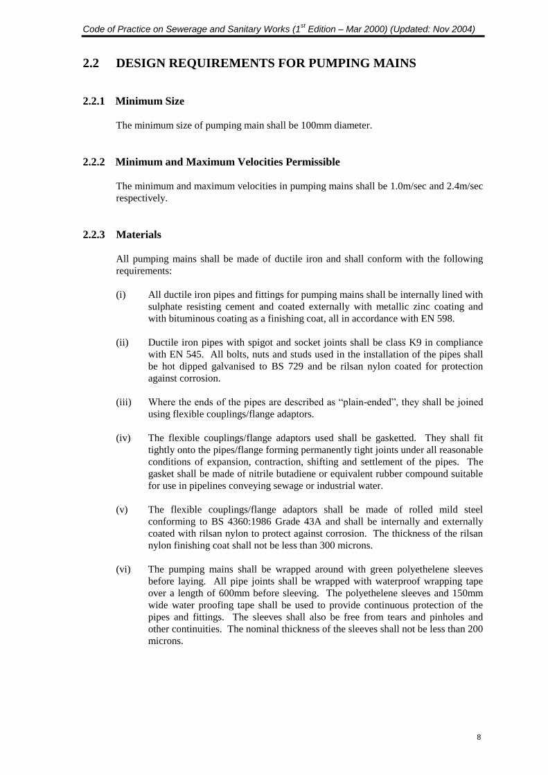
2.2 DESIGN REQUIREMENTS FOR PUMPING MAINS
2.2.1 Minimum Size
The minimum size of pumping main shall be 100mm diameter.
2.2.2 Minimum and Maximum Velocities Permissible
The minimum and maximum velocities in pumping mains shall be 1.0m/sec and 2.4m/sec
respectively.
2.2.3 Materials
All pumping mains shall be made of ductile iron and shall conform with the following
requirements:
(i) All ductile iron pipes and fittings for pumping mains shall be internally lined with
sulphate resisting cement and coated externally with metallic zinc coating and
with bituminous coating as a finishing coat, all in accordance with EN 598.
(ii) Ductile iron pipes with spigot and socket joints shall be class K9 in compliance
with EN 545. All bolts, nuts and studs used in the installation of the pipes shall
be hot dipped galvanised to BS 729 and be rilsan nylon coated for protection
against corrosion.
(iii) Where the ends of the pipes are described as “plain-ended”, they shall be joined
using flexible couplings/flange adaptors.
(iv) The flexible couplings/flange adaptors used shall be gasketted. They shall fit
tightly onto the pipes/flange forming permanently tight joints under all reasonable
conditions of expansion, contraction, shifting and settlement of the pipes. The
gasket shall be made of nitrile butadiene or equivalent rubber compound suitable
for use in pipelines conveying sewage or industrial water.
(v) The flexible couplings/flange adaptors shall be made of rolled mild steel
conforming to BS 4360:1986 Grade 43A and shall be internally and externally
coated with rilsan nylon to protect against corrosion. The thickness of the rilsan
nylon finishing coat shall not be less than 300 microns.
(vi) The pumping mains shall be wrapped around with green polyethelene sleeves
before laying. All pipe joints shall be wrapped with waterproof wrapping tape
over a length of 600mm before sleeving. The polyethelene sleeves and 150mm
wide water proofing tape shall be used to provide continuous protection of the
pipes and fittings. The sleeves shall also be free from tears and pinholes and
other continuities. The nominal thickness of the sleeves shall not be less than 200
microns.
Code of Practice on Sewerage and Sanitary Works (1st Edition – Mar 2000) (Updated: Nov 2004)
9
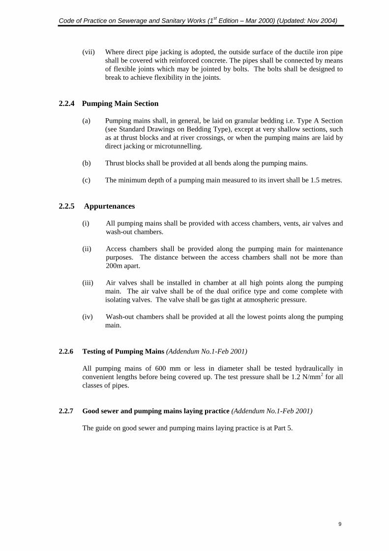
(vii) Where direct pipe jacking is adopted, the outside surface of the ductile iron pipe
shall be covered with reinforced concrete. The pipes shall be connected by means
of flexible joints which may be jointed by bolts. The bolts shall be designed to
break to achieve flexibility in the joints.
2.2.4 Pumping Main Section
(a) Pumping mains shall, in general, be laid on granular bedding i.e. Type A Section
(see Standard Drawings on Bedding Type), except at very shallow sections, such
as at thrust blocks and at river crossings, or when the pumping mains are laid by
direct jacking or microtunnelling.
(b) Thrust blocks shall be provided at all bends along the pumping mains.
(c) The minimum depth of a pumping main measured to its invert shall be 1.5 metres.
2.2.5 Appurtenances
(i) All pumping mains shall be provided with access chambers, vents, air valves and
washout chambers.
(ii) Access chambers shall be provided along the pumping main for maintenance
purposes. The distance between the access chambers shall not be more than
200m apart.
(iii) Air valves shall be installed in chamber at all high points along the pumping
main. The air valve shall be of the dual orifice type and come complete with
isolating valves. The valve shall be gas tight at atmospheric pressure.
(iv) Wash-out chambers shall be provided at all the lowest points along the pumping
main.
2.2.6 Testing of Pumping Mains (Addendum No.1-Feb 2001)
All pumping mains of 600 mm or less in diameter shall be tested hydraulically in
convenient lengths before being covered up. The test pressure shall be 1.2 N/mm2 for all
classes of pipes.
2.2.7 Good sewer and pumping mains laying practice (Addendum No.1-Feb 2001)
The guide on good sewer and pumping mains laying practice is at Part 5.
Code of Practice on Sewerage and Sanitary Works (1st Edition – Mar 2000) (Updated: Nov 2004)
10
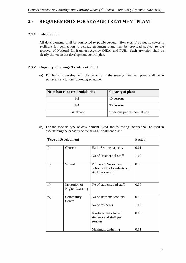
2.3 REQUIREMENTS FOR SEWAGE TREATMENT PLANT
2.3.1 Introduction
All developments shall be connected to public sewers. However, if no public sewer is
available for connection, a sewage treatment plant may be provided subject to the
approval of National Environment Agency (NEA) and PUB. Such provision shall be
clearly shown on the development control plan.
2.3.2 Capacity of Sewage Treatment Plant
(a) For housing development, the capacity of the sewage treatment plant shall be in
accordance with the following schedule:
No of houses or residential units Capacity of plant
1-2 10 persons
3-4 20 persons
5 & above 5 persons per residential unit
(b) For the specific type of development listed, the following factors shall be used in
ascertaining the capacity of the sewage treatment plant.
Type of Development Factor
i) Church: Hall - Seating capacity
No of Residential Staff
0.01
1.00
ii) School: Primary & Secondary
School - No of students and
staff per session
0.25
ii) Institution of
Higher Learning
No of students and staff
0.50
iv) Community
Centre:
No of staff and workers
No of residents
Kindergarten - No of
students and staff per
session
Maximum gathering
0.50
1.00
0.08
0.01

Code of Practice on Sewerage and Sanitary Works (1st Edition – Mar 2000) (Updated: Nov 2004)
11
Type of Development Factor
v) Factory: No of Workers -
One shift per 24 hours
Two/Three shifts per 24
hours.
0.50
1.00
vi) Market: No of hawkers and
employees
0.25
vii) Hawker /
Cooked
Food Centre:
No of stalls
1.75
viii) Cinema: Hall - seating capacity
No of staff
0.03
0.50
ix) Bar & Snack
Bar,
Coffee-House,
Restaurant:
Seating capacity
0.20
x) Hotel: No. of beds
No of staff
0.70
0.50
xi) Office: No of staff
0.50
xii) Park Maximum no of persons
expected to use the park
0.02
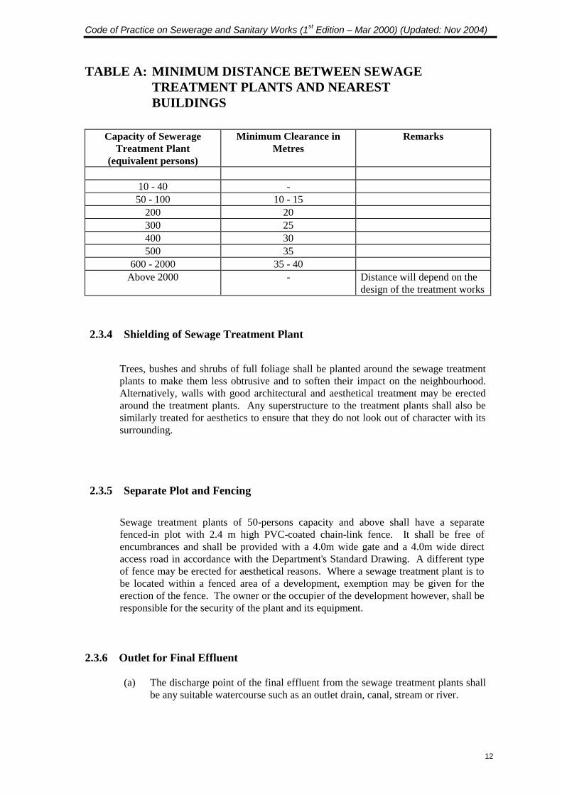
2.3.3 Location of Sewage Treatment Plant
Sewage treatment plants shall be sited as far away as possible from the
residential houses. The recommended minimum distance between the
sewage treatment plants and the nearest building is given in Table A.
Code of Practice on Sewerage and Sanitary Works (1st Edition – Mar 2000) (Updated: Nov 2004)
12
TABLE A: MINIMUM DISTANCE BETWEEN SEWAGE
TREATMENT PLANTS AND NEAREST
BUILDINGS
Capacity of Sewerage
Treatment Plant
(equivalent persons)
Minimum Clearance in
Metres
Remarks
10 - 40 -
50 - 100 10 - 15
200 20
300 25
400 30
500 35
600 - 2000 35 - 40
Above 2000 - Distance will depend on the
design of the treatment works
2.3.4 Shielding of Sewage Treatment Plant
Trees, bushes and shrubs of full foliage shall be planted around the sewage treatment
plants to make them less obtrusive and to soften their impact on the neighbourhood.
Alternatively, walls with good architectural and aesthetical treatment may be erected
around the treatment plants. Any superstructure to the treatment plants shall also be
similarly treated for aesthetics to ensure that they do not look out of character with its
surrounding.
2.3.5 Separate Plot and Fencing
Sewage treatment plants of 50-persons capacity and above shall have a separate
fenced-in plot with 2.4 m high PVC-coated chain-link fence. It shall be free of
encumbrances and shall be provided with a 4.0m wide gate and a 4.0m wide direct
access road in accordance with the Department's Standard Drawing. A different type
of fence may be erected for aesthetical reasons. Where a sewage treatment plant is to
be located within a fenced area of a development, exemption may be given for the
erection of the fence. The owner or the occupier of the development however, shall be
responsible for the security of the plant and its equipment.
2.3.6 Outlet for Final Effluent
(a) The discharge point of the final effluent from the sewage treatment plants shall
be any suitable watercourse such as an outlet drain, canal, stream or river.

Code of Practice on Sewerage and Sanitary Works (1st Edition – Mar 2000) (Updated: Nov 2004)
13
(b) The Qualified Person shall ensure that there is a suitable watercourse in the
vicinity of the sewage treatment plant for the discharge of the final effluent at
the planning stage. The discharge point for the final effluent shall be clearly
indicated in the detailed plans.
2.3.7 Temporary Septic Tank
(a) The provision of temporary septic tank in water and urban river catchment areas
is strictly prohibited. Temporary septic tanks may be permitted in non-water
and urban river catchment areas where there is no sewer in its vicinity subject to
the approval of NEA & PUB. The use of temporary septic tanks shall not be
more than three years.
(b) Where a temporary septic tank is permitted, the tank shall be designed based on
a flow rate of 270 litres per person per day and with a minimum capacity of
2700 litres. The retention time shall be 24 hours.
(c) The temporary septic tank shall be maintained by the owner or occupier of the
development.
2.3.8 Design Guidelines for Sewage Treatment Plants
(a)
Unless otherwise required, the sewage treatment plant shall be designed with
physical and biological treatment processes, capable of producing a stable final
effluent to the satisfaction of the NEA & PUB. The standard for the final
effluent quality shall be:
Biochemical Oxygen Demand (BOD5) : 20 milligrams per litre
Suspended Solids (SS) : 30 milligrams per litre
(BOD5 is defined as the Biochemical Oxygen Demand of the effluent in 5 days
measured at 20C).
The sewage treatment plant shall have sludge treatment and pre-disposal storage
facilities. The methods of treatment and disposal of the final effluent shall be
subject to the approval of NEA & PUB.
(b) No chemical treatment processes shall be used for the treatment of sewage to
the required standard.
(c) In specific cases, tertiary treatment and/or disinfection processes to obtain a
higher grade effluent quality may be required by the PUB or NEA.
(d) The sewage treatment plant shall be designed in compliance with the
requirements herein and endorsed by a Qualified Person.
Code of Practice on Sewerage and Sanitary Works (1st Edition – Mar 2000) (Updated: Nov 2004)
14
(e) The design loading criteria of each and every component treatment process
units shall be set out and supported with design calculations (for structural,
process and hydraulics engineering), and detailed hydraulics and process line
schematic drawings endorsed by a Qualified Person.
(f) The sewage treatment plant shall be supported on a permanent foundation.
(g) The sewage treatment plant shall be designed to the following design
requirements:
(i) Hydraulic conveying capacity based on design peak factor of 3 times the
design average daily flow.
(ii) The incoming sewage shall be lifted up by pumping, and thereafter
carried through the treatment process units and finally discharged all by
gravity flow. No pumping of final effluent is allowed.
(iii) There shall be an overflow pipe located at an appropriate level in the inlet
chamber or pump well to allow sewage overflow to the outlet drain in the
event of plant upsets or power failure.
(iv) The plant, its appurtenances and the effluent outlet pipe shall be set above
the minimum platform level stipulated by the Drainage Management
Division, 3P Network Department (PUB).
(v) The sewage treatment plant shall have facilities to ensure that the
treatment processes operate effectively throughout all diurnal variations
of sewage flow into the plant.
(vi) Sludge retention in the primary settling or other significant sludge
producing process units shall be not less than 30 days design sludge
production rate. This shall be complete with sludge draw-off pipeline.
No sludge drying beds are to be used.
(vii) The plant shall be self-operating, based on simple settings that are self-
adjusting as far as possible and which require periodic and infrequent
monitoring and resetting.
(viii) Airtight covers shall be installed over the whole plant to contain odour
and prevent the breeding of insects. These covers shall be of segments of
lightweight material and be easily removed and reinstalled without the
need of heavy lifting equipment to facilitate plant maintenance work.
(ix) The plant material used shall be made of corrosion resistant type or be
adequately coated with protective material to withstand and endure the
sewerage environment.
(x) Sampling pipelines shall be provided at strategic locations of the
individual treatment process units to facilitate representative sampling for
analysing the performance of the treatment process units.
(xi) A dosing chamber shall be provided for the dosing of sodium
hypochlorite to disinfect the final effluent. It shall be designed with 2
minutes retention time of the daily peak flow rate.
(xii) The plant design shall be proven with a track record of operation in the
previous 5 years.
Code of Practice on Sewerage and Sanitary Works (1st Edition – Mar 2000) (Updated: Nov 2004)
15
(h) Upon commissioning, the sewage treatment plant shall be test-run and
performance tested and certified to be performing in compliance with the
design criteria to achieve the standard for the final effluent quality. Test
analyses shall be carried out at an accredited laboratory. The Qualified Person
shall duly endorse all tests and certification.
(i) The requirements on Mechanical and Electrical equipment are set out in
Section 2.4.
Code of Practice on Sewerage and Sanitary Works (1st Edition – Mar 2000) (Updated: Nov 2004)
16
2.4 MECHANICAL & ELECTRICAL (M&E) REQUIREMENTS
FOR SEWERAGE INSTALLATIONS
2.4.1 Mechanical Requirements
2.4.1.1 Pumps
(a) Pump bodies and impellers shall be of corrosion resistant material suitable for the
pumped media (e.g. cast iron or stainless steel).
(b) Reflux and isolating valves shall be provided for the pumping system.
(c) A minimum of two pumps, comprising the duty and standby pumps, shall be
provided for the sewerage installation. Where two pumps are provided, one shall
be the duty pump and the other the standby pump. The standby pump shall be
activated in the event the duty pump fails or during high level.
(d) The pumps shall be capable of automatic starting and stopping. Controls shall
also be provided for automatic interchange of duty and standby pumps after each
cycle of operation.
2.4.1.2 Sewage Pumps
(a) Sewage pumps shall be capable of passing long fibrous materials.
(b) Sewage pumps of up to 2.2 kW shall be capable of passing solids of 64 mm in
diameter without chokage and shall be with discharge pipes of minimum 75 mm
diameter.
(c) Sewage pumps above 2.2 kW shall be capable of passing solids of 75 mm in
diameter without chokage and shall be with discharge pipes of minimum 100 mm
diameter.
2.4.1.3 Sewage Ejector / Solids Divertor
(a) The pit for the sewage ejector or solids divertor installation shall be adequately
sized to accommodate the tanks, pumps, dewatering sump pump, valves,
pipework etc. and shall include working space for maintenance. Generally, a
room shall be provided and the pit shall be of minimum 3m x 3m size. This
provision enables the following functional requirements to be met:
(i) A safe working environment;
(ii) Adequate security and protection from vandalism; and
(iii) Free from obstructions at all times for maintenance purposes.
Code of Practice on Sewerage and Sanitary Works (1st Edition – Mar 2000) (Updated: Nov 2004)
17
However, for cases where a room is not provided, the functional requirements
shall nevertheless be complied with as follows:
(1) Adequate forced ventilation system shall continue to be provided for the
safe working environment of workers operating and working in the
sewerage installation;
(2) The pit shall be located away from driveway;
(3) Measures shall be provided all round the pit to prevent water flowing into
it and to prevent vehicles or other items from obstructing access and
maintenance.
(4) The pit shall be securely covered with lockable doors or covers;
(5) The access opening for the pit shall extend over the whole of the ejector/
divertor tank and pumps;
(6) Lifting equipment shall be provided for the installation.
(b) Where pumping equipment are needed to handle waste discharge from
restaurants, food centres and markets located at basements, solids divertors shall
be provided. However, for cases where grease traps are provided upstream of the
sewage pumping installation, sewage ejectors may be provided in lieu of solids
divertors.
(c) Sewage ejector / solids divertor tank shall be made of corrosion resistant material
suitable for the pumped media (eg. stainless steel). The tank shall be mounted on
a concrete plinth.
(d) Access opening shall be provided directly above the sewage ejector / solids
divertor tank and pumps for ease of maintenance.
(e) For solids divertor, a minimum clearance of 1.8 m between levels of the pipe
invert and the solids divertor floor is required to ensure that the incoming pipe
invert is always higher than the outlet / bypass pipe of the solids divertor.
(f) Air release pipes with isolating valves and air release valves shall be provided for
the separating chamber and the two-way valves of the divertor tank.
(g) Dewatering submersible sump pump in the sewage ejector / solids divertor pit
shall be provided and shall pump into the ejector / divertor discharge pipe.
(h) Dewatering sump pump shall be provided with reflux and isolating valves.
(i) Access ladders and handholds of suitable material (e.g. aluminium alloy or glass
reinforced plastic) shall be provided for the ejector / divertor pit.

Code of Practice on Sewerage and Sanitary Works (1st Edition – Mar 2000) (Updated: Nov 2004)
18
(j) Adequate lighting and a water tap shall be provided for the ejector / divertor
installation.
(k) Perforated strainer plate and cone baffle of the solids divertor shall be made of
stainless steel. Strainer plate shall be of the removable type.
(l) Vent pipe of not less than 75mm shall be provided for the ejector / divertor tank.
It shall be connected to the main vent stack.
2.4.1.4 Pump Sump
(a) A screen chamber shall be provided before the pump sump (except for car park
pump sump). The screen shall be made of aluminium alloy or stainless steel.
(b) Access opening shall be provided directly above the pumps for ease of
maintenance.
(c) Ladders installed within pump sump and screen chamber shall be of suitable
material (e.g. stainless steel or GRP).
(d) An overflow pipe to the downstream sewer shall be provided, where possible.
(e) Lifting equipment, of safe working load, shall be provided.
(f) Adequate ventilation system shall be provided for the installation.
(g) Adequate lighting and a water tap shall be provided.
(h) When the depth of pump sump or screen chamber exceeds 6 m, intermediate
platforms shall be provided. Aluminium alloy (or superior material) handrail and
safety chain shall be provided at the intermediate platform.
2.4.1.5 Sewage Treatment Plant (STP)
(a) Where pumps are required, the STP shall be designed so that the pump is used to
lift crude sewage or settled sewage.
(b) The STP shall comply with the following:
(i) The requirements for pump sump as detailed in Clause 2.4.1.4.
(ii) A switchroom to house the switchboard shall be provided with adequate
lighting and one power point.
(iii) A high sewage level indicating system comprising a float activated
revolving / flashing light and reflective sign plate with hotline number shall
be provided and installed in a prominent location.
Code of Practice on Sewerage and Sanitary Works (1st Edition – Mar 2000) (Updated: Nov 2004)
19
(c) For dosing siphon, cleaning eye shall be incorporated in the discharge pipe bend.
(d) Mercury seals shall not be used.
2.4.1.6 Screening
Screens of suitable corrosion resistant material (e.g. stainless steel) shall be provided to
prevent large objects from entering the installation so as not to cause damage to the
pumping equipment and disruption to the pumping system.
2.4.1.7 Lifting Equipment
(a) Lifting equipment of adequate safe working load shall be provided for the
maintenance and replacement of equipment in the sewerage installation. The
lifting equipment shall be able to traverse the installation and be able to reach the
equipment required for lifting with ease. The lifting equipment shall be inspected
by an approved person and shall be registered with the Factory Inspectorate,
Ministry of Manpower.
(b) Generally, two chain blocks shall be provided. The chains shall be of adequate
length of not less than 5m and shall be capable of lifting safely the heaviest
equipment or plant.
2.4.2 Electrical Requirements
(a) The electrical installations shall comply with the latest Singapore Standard (SS)
CP 5, SS CP 16 and other relevant CPs.
(b) An electric switchroom shall be provided with the switchboard/motor control
centre of enclosure rating exceeding or equal to IP41. Where approved, an open
shelter with a weatherproof switchboard may be allowed. The switchboard shall
be provided with an outer enclosure to not less than IP54 rating and made of non-
corroding material such as stainless steel or aluminium alloy material.
(c) The electrical provisions shall include the following items:
(i) Main isolating fused switch or circuit breaker.
(ii) Separate fused switch or circuit breaker for each pump.
(iii) Automatic motor starters with motor overload protection incorporating
single-phase protection and automatic control of pump motors. Each motor
starter shall be provided with indicating lights, start-stop and hand reset
push button and manual/automatic selector switches.
Code of Practice on Sewerage and Sanitary Works (1st Edition – Mar 2000) (Updated: Nov 2004)
20
(iv) Automatic starting and stopping of pumps using level sensing float
switches or electrodes. The standby pumps shall also operate when the
level is high and with regular automatic interchange of duty and standby
pumps. To disallow “hunting” of the pumps, a separate float switch or
electrode shall be provided for each level. An earth-return electrode shall
be provided for the electrode control system. The float switches shall be
shackled to a stainless steel chain.
(d) A standby generator or an alternate power source with automatic electricity
changeover shall be provided.
(e) The level control system shall be operated with voltage not exceeding 24-volt AC
system.
(f) Adequate lighting shall be provided for the sewerage installation. Fluorescent
lamp(s) with corrosion resistant fittings shall be provided.
2.4.3 The owner/developer/occupier of the sewerage installation to be taken over by PUB shall
pay the cost of all repairs to the installation, fencing etc. for a period of one year from
the date of taking over.
2.4.4 For installations to be taken over by PUB, the following shall also be provided and
complied with:
(i) Elevated break water tank made of approved fibreglass or stainless steel.
(ii) Separate electricity and water meters, which shall be located within the
compound of the installation.
(iii) 2.4 m high PVC-coated chain link fencing and 4.0 m wide separate vehicular
access road with gate, complying with the Department’s Standard Drawings.
(iv) Disintegrators or channel screen disintegrators.
(v) Inlet, channel and dividing wall rising spindle penstocks.
(vi) Fixed supply and exhaust ventilation systems for the wet well and supply
ventilation system for the dry well.
(vii) Handrailing, ladders, safety cages and hand holds.
(viii) Standby generator with automatic transfer system and daily fuel tank.
(ix) Standby generator building or a containerised standby generator.
(x) Underground bulk fuel tank.
(xi) Odour and acoustic control facilities.
(xii) Toilet facilities.
Code of Practice on Sewerage and Sanitary Works (1st Edition – Mar 2000) (Updated: Nov 2004)
21
(xiii) 400V electrical Motor Control Centre MCC.
(xiv) Spares for the equipment (In the case of sewage treatment plants, spares shall be
sufficient for 2 years of operation.)
(xv) Operation & Maintenance manuals (process and equipment etc.).
(xvi) Other equipment and requirements as imposed by the Department, which can be
obtained from the Internet Website at URL Address: http://www.pub.gov.sg.
2.4.5 For all installations to be taken over by PUB, a Remote Telemetry Unit (RTU) shall be
installed. The requirements for the RTU system are available in the Internet Website at
URL Address : http://www.pub.gov.sg
Code of Practice on Sewerage and Sanitary Works (1st Edition – Mar 2000) (Updated: Nov 2004)
22
PART 3
SANITARY WORKS
3.1 SANITARY DRAINAGE SYSTEM
3.1.1 Objective
The sanitary drainage system shall be designed, installed, and maintained so as to
convey and discharge wastewater into the sewerage system without causing a
nuisance or danger to health arising from leakage, blockage or surcharge.
3.1.2 Design Criteria
(a) The system shall convey only wastewater from within the premises to the
sewerage system. Rainwater shall not be discharged into sanitary drainage
system.
(b) The size, length and material shall be chosen to facilitate maintenance and reliable
service.
(c) Bends or kinks are to be avoided in any branch/main drain-line.
(d) The branch/main drain-line shall be of the same diameter and laid using the same
material throughout its entire length.
(e) The branch/main drain-line shall have a constant gradient. The size and gradient
of the drain-line shall be chosen to provide adequate carrying capacity and also
allow for adequate ventilation.
(f) In addition, the choice of gradient for the branch/main drain-line shall be such as
to maintain self-cleansing velocity (0.9 m/sec) and not to exceed scouring velocity
(2.4 m/sec) under normal discharge condition.
(g) The drain-line laid shall be watertight and subjected to a water test under a static
head of not less than 1.5 metre of water at the upstream end of the line. The water
test shall be done after pipe laying and before placing concrete for haunching or
encasing. (Addendum No.1-Feb 2001)
(h) Main drain-lines shall not be sited within road reserve and drainage reserve.
(i) A floor trap shall be provided to receive connection from waste appliances before
discharging into the branch drain-line. The trap shall have a minimum water seal
of 50mm for exclusion of foul air from the sanitary drainage system.
(j) As required by NEA, adequate measures, such as installation of anti- mosquito
devices at the floor trap, shall be taken to prevent mosquitoes from breeding in
the water seal of the floor trap.
Code of Practice on Sewerage and Sanitary Works (1st Edition – Mar 2000) (Updated: Nov 2004)
23
(k) Food shops shall be provided with grease trap/interceptor of adequate capacity so
as to prevent discharge of oils, fats and grease directly into the sewerage system.
The grease traps shall be maintained such that the effluent from the grease traps
shall meet the standards for discharging into the sewerage system.
(l) For commercial/shopping complex, separate grease waste discharge pipe
connected to a separate discharge stack for future connection to grease trap shall
be provided in advance to serve commercial units which are expected to be used
as food shops. In addition, sufficient space shall be allocated for siting the grease
traps which are to be provided in future to serve the future food shops.
(m) No uPVC pipe shall be used for sewer connection. The connecting drain-line from
last inspection chamber to an existing/new manhole shall not be smaller than
200mm in diameter. This is regardless of the size of the existing sewer.
(n) For drain-line connection from the last inspection chamber to an existing 150mm
diameter sewer via raised junction or ‘Y’ junction, it shall follow the size of the
existing 150mm diameter sewer.
(o) The drainage system serving the following areas shall be connected to surface
storm-water drains.
(i) Common corridors/common verandahs
(ii) Covered areas (void deck except wash area)
(iii) Covered play areas
(iv) Multi-storey car parks (except car washing areas)
(v) Open areas in backyards/courtyards/airwells and other uncovered paved
areas within premises where rainwater flows are expected
(vi) Pump islands at petrol stations
(vii) Footbaths, open shower points in public and private swimming pools
3.1.3 Acceptable Design/ Practices
(1) Numerals in parenthesis in this Code of Practice refer to the corresponding drawings.
(2) All text shall be read in conjunction with drawings that provide guidelines for
recommended practices.
3.1.3.1 Branch Drain-line (3-1) (3-2)&(3-3)
(a) The branch drain-line shall have a minimum diameter of 100mm. The length
shall preferably not exceed 10 metres.
(b) Where the depth of branch drain-line to an inspection chamber exceeds 1.5 metres
the provision of backdrop/ tumbling bay is recommended and the minimum
diameter of the branch drain-line shall be 150mm.
(c) The branch drain-line shall be connected obliquely in the same direction of flow
as the main drain-line within an inspection chamber. The invert of the branch
drain-line at the inspection chamber shall be above the horizontal diameter of the
main channel.
Code of Practice on Sewerage and Sanitary Works (1st Edition – Mar 2000) (Updated: Nov 2004)
24
3.1.3.2 Main Drain-line (3-1)
(a) The main drain-line shall have a minimum diameter of 150mm and distance
between inspection chambers shall not exceed 50 metres.
(b) Inspection chambers shall be provided at all bends, junctions, at changes to the
direction of flow or gradient and at changes in pipe diameter or materials.
(c) Where there is any significant difference in invert levels between incoming drain-
line and the inspection chamber, a backdrop (3-4) or tumbling bay (3-4) connection
shall be made at the inspection chamber.
3.1.3.3 Drain-line under Building (3-5)
(a) Every sanitary drain-line shall be laid outside buildings wherever practicable.
(b) Where a drain-line passes under a building, it shall be of heavy duty material (e.g.
Ductile iron pipes) and laid in a straight run for the whole distance and shall be
encased in concrete of adequate thickness (3-5).
(c) If the drain-line has to pass through a basement wall or lay within basement slab,
it shall be of heavy-duty material (e.g. ductile iron pipes). Provision in the design
shall be made to take care of differential settlement, to reduce the risk of shear
fracture, to ensure water tightness and reliable service.
3.1.3.4 Drain-line under Driveway and Car park (3-5)
The drain-line under driveway and car park shall be of heavy-duty material (e.g.
Ductile iron pipes) and appropriately designed to withstand vehicular loading. (e.g.
concrete encasement can be provided for the pipes to increase its strength).
3.1.3.5 Bedding, Haunching and Backfilling to Drain-line (3-5)&(3-7)
The design of bedding and haunching for drain-lines depends on the diameter of the
pipe, the depth at which it is laid, the trench width, the traffic or other super-imposed
loading and the prevailing site conditions. The bedding and haunching increase the
drain-line ability to carry the loading. On soft or yielding ground, piling has to be designed. The bedding details are shown in Drawing No 3-5.
3.1.3.6 Inspection Chamber and Ventilation (3-7)
(a) Inspection chamber shall be of brickwall or reinforced concrete construction and
be watertight. It shall also be designed to minimise the risk of blockage, facilitate
maintenance and prevent flotation in ground where the water table is high. It shall
have adequate depth to allow ease of maintenance.
Code of Practice on Sewerage and Sanitary Works (1st Edition – Mar 2000) (Updated: Nov 2004)
25
(b) The first inspection chamber shall be ventilated except when there is a
discharge/ventilating stack of not less than 100mm diameter or where provision of
the ventilation stack would cause odour nuisance to the surroundings.
(c) Details of construction of inspection chamber are shown in Drawing No 3-7.
Where the inspection chamber exceeds 2.5 metres deep, it has to be specially
designed. Heavy-duty cast iron frame and cover shall be used in every drive-way
and car park.
(d) At the inspection chamber, branch drain-line shall be connected to the main drain-
line at a level above the invert level and not less than half the diameter of the main
drain-line to ensure smooth flow.
(e) Measures shall be taken to protect the inspection chamber sited within 2.5 m of
the top or bottom of an embankment where its slope is steeper than 1:1.5 (e.g.
retaining wall).
(f) The last inspection chamber shall be located within 2.5 metres of the lot boundary.
(g) For food shop, no inspection chamber shall be sited within the areas where food is
prepared, cooked, stored or served; or other areas where they are likely to give rise
to nuisance, health or hygiene hazards during maintenance.
3.1.3.7 Floor Trap at Ground /First Storey Level (3-6)
(a) The minimum internal diameter of the outlet of the floor trap at ground/first storey
level connecting directly to an inspection chamber shall be 100mm.
(b) The waste pipe shall be connected to a floor trap at the riser below grating and
above the water seal of the trap.
(c) Where the floor trap is intended to receive sullage water, it shall be located within
covered areas and not subject to surface water runoffs from rain. The floor trap
shall be fixed with a frame and grating slightly below the paved floor.
(d) Where a floor trap is sited in a location likely to receive rainwater or on unpaved
ground, it shall be fixed with a frame and an unperforated cover.
(e) The maximum depth for a floor trap shall not exceed 600mm to facilitate
maintenance. A sump may have to be provided for deeper floor trap.
3.1.3.8 Wash Area (3-8)
The wash area shall be constructed under a roof and appropriately kerbed and
designed so that no rainwater can enter the sewer. It shall be provided with either a
floor waste connecting to floor trap or a floor trap connecting directly to an
inspection chamber. The details are shown in Drawing No 3-8.
Code of Practice on Sewerage and Sanitary Works (1st Edition – Mar 2000) (Updated: Nov 2004)
26
3.1.3.9 Provisions for Sullage Water Discharge (3-6)(3-10a)& (3-11a)
(a) Sullage water discharge is required to be connected to sewerage system. The
specific requirements for sullage water discharge are as follows: -
Connection via Floor Trap(3-6)
(i) Backwash from swimming pool filter
(ii) Boiler blowdown via cooling pit
(iii) Covered wash area/service yard within building
(iv) Steam condensate via cooling pit
(v) Waste water from cooling tower
Connection via Cast Iron Gully Trap with Strainer
(Standard Drawing No. PUB/WRN/STD/044)
(vi) Bin centre(3-11a)
(vii) Refuse chute(3-11a)
Connection via Cast Iron Garage Gully Trap with Strainer
(Standard Drawing No. PUB/WRN/STD/043)
(viii) Basement car park
(1) For Basement car park which is not exposed to rain, the
drainage system for the car-parking areas may be
connected to sewerage system. In such case, adequate
numbers of floor waste shall be provided to convey
wastewater into the sewerage system so as to prevent
flooding or stagnation of water. A cast iron gully trap
(Standard Drawing No. PUB/WRN/STD/043) shall be
provided before connection to the inspection chamber. At
the entrance/exit to the basement car park, minimum crest
level shall be provided to prevent any ingress of rainwater.
(2) For Basement car park which is partially exposed to rain or
the car-parking areas are likely to subject to surface water
runoffs from rain, the drainage system serving the car
parking areas (except car washing areas) shall be connected
to surface storm-water drain via an oil interceptor if
necessary. In such case, no floor wastes are required. The
water discharging into open drain shall meet the discharge
standards as specified by NEA.
Connection via Petrol and Oil Interceptor
(Standard Drawing No. PUB/WRN/STD/042)
(ix) Lubrication bay and car washing bay of petrol station
(x) Motor garage
(b) Waste sumps may be provided at multiple junctions of the waste
discharge pipes to facilitate ease of maintenance. Details of waste sump
are shown in Drawing No 3-10a.
Code of Practice on Sewerage and Sanitary Works (1st Edition – Mar 2000) (Updated: Nov 2004)
27
3.1.3.10 Provision of Grease Trap for Food Shop (3-9a)
(a) The grease trap shall be sited at locations to facilitate maintenance and will not
give rise to nuisances, health hazards and hygiene problems during its operation
and maintenance. It shall not be sited within areas where food is prepared, cooked,
served or stored.
(b) Standard circular grease traps (Standard Drawings No PUB/WRN/STD/040 and
PUB/WRN/STD/041) shall be provided.
(c) Portable grease interceptor may be used where the provision of standard grease
traps is not feasible. The portable grease interceptor is allowed to be installed
within the individual food shops provided that it must be of a suitable design to
allow for easy removal for maintenance.
(d) All portable grease interceptors shall incorporate a mechanical oil-skimming
device for automatic removal of free-floating grease and oil to a separate grease/
oil container.
(e) Sufficient floor waste/floor trap shall be provided for the discharge of the
sullage water from the kitchen into the grease trap.
3.1.3.11 Sanitary Drainage System for Market (3-12a)
(a) Specially designed floor sump (3-13) shall be provided to collect the sullage water
from the scupper drains within the stalls and at the service corridors and the
common passageways. The details are shown in Drawing No. 3- 12a.
(b) Waste sump (3-10a) shall be sited at service corridors and away from the main public
areas. Inspection chamber shall be sited outside the market proper.
3.1.3.12 Sanitary Drainage System for Shower/Bathroom
Compartment/ Wash Area at Beach Site/Construction
Site/Other area where silt discharge is expected (3-14)
(a) Sullage water from shower/bathroom compartment/wash area shall be discharged
into a silt trap before connection to an inspection chamber. This is to prevent the
sand/silt from entering the sewerage system.
(b) Temporary septic tank is not allowed to serve the temporary work site facilities for
developments located in sewered areas and within the water and urban river
catchment areas. In such cases, temporary sewer connection to existing sewer is to
be provided.
(c) If sewer is not available and the development is located within the water and
urban river catchment areas, Developer will have to bring forward the extension of
public sewer to serve the construction site. During the interim, temporary holding
tanks (i.e. no discharge to sewer/drain) of sufficient capacity (design flow is 200
litres per person per day and minimum capacity is 2000 litres) for sullage water
and portable chemical toilets are to be provided. Licensed Waste Contractor shall
empty the temporary holding tanks/chemical toilets regularly.
Code of Practice on Sewerage and Sanitary Works (1st Edition – Mar 2000) (Updated: Nov 2004)
28
3.1.3.13 Sewer Connection (3-4)
The connection from the last inspection chamber to the sewer/manhole shall be
constructed in accordance with the Department's Standard Drawing
PUB/WRN/STD/007.
3.1.4 Material and Component (Addendum No.1-Feb 2001)
The following materials that comply with the stipulated standards are acceptable for
use in sanitary drainage system viz:
(a) Pipes and Pipe-fittings
(i) uPVC - SS 272 : 1983
(ii) Ductile iron - BS EN 598 : 1995
(iii) Heavy-duty cast iron - BS 4622 : 1970
(iv) Vitrified Clay - BS EN 295 : 1991
(v) Reinforced concrete
- SS 183 : 1978
(b) Manhole/Inspection chamber
frames and covers
- SS 30 : 1999
Code of Practice on Sewerage and Sanitary Works (1st Edition – Mar 2000) (Updated: Nov 2004)
29
3.2 SANITARY PLUMBING SYSTEM
3.2.1 Objectives
The sanitary plumbing system for any premises shall be designed, installed and
maintained so as to carry away wastewater from the building into the sewerage
system quickly without creating any nuisance or risk of injury to health.
3.2.2 Design Criteria
(a) No sanitary plumbing system shall be used to convey rainwater.
(b) The sanitary plumbing system shall comprise the minimum pipework and be
designed to provide adequate capacity to cater for the discharge from the sanitary
appliances to which it is connected.
[Reference may be made to the British Standard (BS 5572), U.S - National
Standard Plumbing Code or other acceptable standards for the sizing of pipework
to provide reliable service. However, the minimum sizes for discharge stacks/
pipes and ventilating stacks/ pipes to be provided shall be in accordance with the
requirements laid down in this Code]
(c) The sanitary plumbing system shall be designed to exclude foul air from the
discharge pipes or stacks from entering the buildings. In this connection, water
seals of sufficient depth (not less than 50 mm) are required to be provided at
sanitary appliances and floor traps. The system shall be designed and installed to
avoid water seal loss in trap arising from pressure fluctuations through the
provision of ventilating pipes/stacks or adequate sizing of discharge stacks as
appropriate, for the sanitary plumbing system.
(d) In the case of residential buildings where the sanitary appliances are closely
grouped around a discharge stack, the "single stack system" may be adopted for
buildings up to six storeys high and the "ventilated stack system" for buildings up
to thirty storeys high.
(e) In the design and installation of the sanitary plumbing system, attention shall be
given to the need to facilitate access for maintenance and repairs. Access cover
and/or cleaning eyes shall be appropriately positioned to enable cleaning, clearing
of chokages and inspection to be carried out.
(f) The discharge pipe shall not be located in places where it can cause health and
safety hazards such as locating the discharge pipe above any potable water storage
tank and electrical transformer/ switchgear.
Code of Practice on Sewerage and Sanitary Works (1st Edition – Mar 2000) (Updated: Nov 2004)
30
(g) The discharge pipe shall also not be located in places where it can give rise to
nuisance conditions during maintenance. In particular, for buildings under the
Land Titles (Strata) Act, discharge pipes shall not run above bedrooms, living
room, dining room or kitchen areas of the strata unit below. Where such routing
cannot be avoided, suitably designed service duct to allow access for maintenance
shall be provided.
(h) As required by NEA, adequate measures, such as installation of anti- mosquito
devices at the floor trap, shall be taken to prevent mosquitoes from breeding in
the water seal of the floor trap.
(i) For sewage collected below ground level, sewage ejector, solids divertor or other
appropriate pumping installation will have to be provided.
(j) The sanitary plumbing system shall be tested for water and air tightness either by
means of an air test, smoke test or water test for soundness of the installation.
Reference can be made to BS 5572 for details.
3.2.3 Acceptable Design / Practice
3.2.3.1 Fully Ventilated Sanitary Plumbing System (3-15a)&(3-16a)
(a) The fully ventilated system is used where there are large numbers of sanitary
appliances in range or where they have to be widely dispersed.
(b) In the fully ventilated system, separate discharge and ventilating stacks have to be
provided and be extended to the atmosphere. Individual traps/soil sanitary
appliances connected directly to the discharge pipe or stack need to be provided
with branch ventilating pipe which is connected to ventilating stack.
(c) The discharge stack shall have a uniform diameter of not less than 100mm
throughout its entire length.
(d) The trap connecting directly to a discharge pipe shall be provided with a branch
ventilating pipe of not less than 50mm in diameter.
(e) The ventilating pipe shall be constructed upwards individually and be connected
to a main ventilating stack. Such connection shall be above the spill over level of
the soil sanitary appliance or floor trap served by such ventilating pipe. The details
are shown in Drawings No. 3-19 & 3-20.
(f) The top end of every ventilating stack shall either terminate as high as the
discharge stack or connect into the discharge stack at a point not less than 150mm
above the spill over level of the topmost soil sanitary appliance or floor trap.
(g) For multi-storey buildings of seven-storey or higher (3-16a), the discharge pipe
serving the second storey shall be connected to a secondary discharge stack of
diameter not less than 100mm. This stack shall be extended to serve as ventilating
stack but may be reduced to 75mm diameter.
(h) Cross venting between the ventilating stack and the discharge stack shall be
provided at every ten storeys.
Code of Practice on Sewerage and Sanitary Works (1st Edition – Mar 2000) (Updated: Nov 2004)
31
3.2.3.2 Single Stack Sanitary Plumbing System (3-17b)
(a) The single stack system may be used for buildings up to six storeys high where
there are single appliances connected to a discharge stack or where the sanitary
appliances/ fittings are closely grouped round a discharge stack which is large
enough to limit pressure fluctuations without the need for a ventilating stack.
(b) The main discharge stack shall have a uniform diameter of not less than 150mm
without offset throughout its entire length. However, for conventional housing, a
main discharge stack of 100mm diameter may be provided.
(c) The length of the discharge pipe connecting to the discharge stack shall not be
more than 2.5m and there shall be not more than two connections made to the
discharge pipe.
3.2.3.3 Ventilated Stack Sanitary Plumbing System (3-18b)
(a) The ventilated stack system may be adopted in situations where there are close
groupings of sanitary appliances around the discharge stack in buildings up to
thirty storeys high.
(b) The main discharge stack shall have a uniform diameter of not less than 150mm
throughout its entire length.
(c) Separates discharge stack (secondary discharge stack) of diameter not less than
100mm shall be provided to serve the second and third storeys. This secondary
discharge stack shall be extended to serve as ventilating stack.
(d) Cross venting between the ventilating stack and the discharge stack shall be
provided at third, sixth, ninth, twelfth, fifteenth, eighteenth, twenty-first, twenty-
fourth and twenty-seventh storeys.
(e) The length of a discharge pipe connecting to the discharge stack shall not be more
than 2.5m and there shall be not more than two connections made to the discharge
pipe.
3.2.3.4 Discharge Pipe/Stack, Ventilating Pipe/Stack for Sanitary
Plumbing System (3-15a) to (3-21)
Unless otherwise indicated, the following clauses are applicable to all the above 3 types
of sanitary plumbing systems:
(a) The discharge pipe shall have a minimum size of 100mm and be made of the same
material throughout its entire length. The pipe shall not be reduced in diameter in
the direction of flow.
Code of Practice on Sewerage and Sanitary Works (1st Edition – Mar 2000) (Updated: Nov 2004)
32
(b) In the case of the "fully ventilated system" and "ventilated stack system", the
discharge stack shall, as far as practicable, not form any offset throughout its
entire length. Where offset is to be made, large radius bends of at least 200mm
radius shall be used and cross venting between the ventilating stack and the
discharge stack is required above and below the offset (3-21).
(c) Swept branch connections from discharge pipe to discharge stack are
recommended. Directly opposite discharge pipes without swept entries shall be at
least 200mm vertically apart so that discharge from one branch into the other is
avoided.
(d) The discharge pipe and discharge stack shall be securely supported or fixed to the
wall or roof slab of the building.
(e) The discharge pipe and discharge stack shall be easily accessible. Access covers
for cleaning eyes shall be positioned to allow cleaning and maintenance
equipment to be easily inserted into the pipework and to permit cleaning or
clearing of all parts of the system. Access cover on the invert of pipe shall be
avoided. Access for rodding and testing shall be provided at or near the foot of
the discharge stack and at junctions of discharge pipe/stack.
(f) The ventilating pipe shall be fixed as close to the crown of the trap as practicable.
Other aspect of the construction of ventilating stack, cross venting, termination of
discharge stack and ventilating stack are shown in Drawing No. 3- 15a, 3-16a, 3-
17b, 3-18b & 3-21.
(g) The ventilation stack shall not be terminated in any private premises or private
roof area that is designed for use by the occupants. To avoid termination of
ventilation stack in private premises or roof areas, the ventilating stack may be
offset or connected to a common pipe of adequate size and extended for
termination in the open air at the highest point of the building or other suitable
location that will not cause smell nuisance or health hazard to the occupants.
The recommended height of the ventilating stack above roof is shown in
Drawing Nos. 3-15a, 3-16a, 3-17b & 3-18b. (Addendum No.1-Feb 2001)
3.2.3.5 Connection of Discharge Stack to Branch Drain-line (3-22)
(a) The discharge stack shall be connected directly to the inspection chamber. Where
individual connections of discharge stacks are impracticable, a common pipe of
adequate size to serve the discharge stacks may be provided to suit connection to a
branch drain-line.
(b) In the case of multi-storey buildings of 7-storey or higher, both discharge and
ventilating stacks are to be connected to inspection chamber. The invert of the
discharge end of the ventilating stack shall be at least one diameter above that of
the discharge stack.

Code of Practice on Sewerage and Sanitary Works (1st Edition – Mar 2000) (Updated: Nov 2004)
33
3.2.3.6 Access to Pipework Enclosure
(a) No pipe other than the ventilating pipe or ventilating stack and waste pipe shall be
encased in columns, beams, walls, or floor slabs.
(b) Discharge pipes or stacks may be accommodated in enclosures such as ducts
which shall be of suitable size and provide ready access openings for maintenance
and testing.
(c) Access openings shall preferably be provided to joints or junctions of discharge
pipes/stacks and other fittings that may require maintenance.
3.2.4 Material and Component (Addendum No.1-Feb 2001)
The following materials that comply with the stipulated standards are acceptable for use
in sanitary plumbing system viz:
(i) uPVC - SS 213 : 1998
(ii) Ductile iron - BS EN 598: 1995
(iii) Hubless cast iron - CISPI : 301 : 1995
- CISPI : 310 : 1995
- BS 6087 : 1990
- ASTM C 564 : 1995
(iv) Spigot/Socket cast iron
- SS 33 : 1975
Code of Practice on Sewerage and Sanitary Works (1st Edition – Mar 2000) (Updated: Nov 2004)
34
3.3 SANITARY APPLIANCES AND FITTINGS
3.3.1 Objectives
Sanitary wares, sanitary pipes and fittings are part of the sanitary plumbing and
drainage system for the conveyance of wastewater from within the premises to the
sewerage system. Its design and construction have a great impact on the proper
functioning of the sanitary plumbing system. The proper selection and installation of
sanitary wares, pipes and fittings will reduce the risk of danger to health arising from
blockage, leakage or surcharge.
3.3.2 Selection/ Design Criteria
(a) The sanitary wares, pipes and fittings, manhole/ inspection chamber frames and
covers used in the sanitary plumbing and drainage system shall be of a type,
size, quality and workmanship as specified in the Code and shall comply with
the Standards prescribed in this Code of Practice. (Addendum No.1-Feb 2001)
(b) Sanitary appliances shall be secured in position and installed in a manner that
facilitate disconnection to the sanitary piping when required. The supports and
brackets used for fixing of the sanitary appliances to wall shall be of adequate
strength to withstand the fully loaded weight of the appliance. In no circumstances
should any pipework be relied upon for support or fixing the appliance.
(c) Connection of Soil Sanitary Appliance
(i) Soil Sanitary Appliance is for the reception and discharge of excretory matter.
Examples of soil sanitary appliances are water closet pan, urinal and bidet etc.
(ii) Direct connection from any water service pipe shall not be made to any part of
a soil sanitary appliance other than a connection through the flushing cistern or
flush valve as detailed under Clauses 3.3.3.2 and 3.3.3.4 of this Section
respectively. This is to prevent contamination of the potable water system.
(iii) The soil sanitary appliance shall have at least one trap with a water seal of not
less than 50 mm before connecting directly to a separate branch drain-line to
an inspection chamber on first storey level or to a discharge pipe on upper
storey level.
(d) Connection of Waste Sanitary Appliance
(i) A waste sanitary appliance is for the reception and discharge of water for
ablutionary, cleaning or culinary purpose. Examples of waste sanitary
appliances are sink, basin, bath and shower tray etc.
(ii) The waste sanitary appliance may be provided with a waste fitting trap for
connection to the waste pipe.
(iii) Waste pipes serving waste sanitary appliances are to be adequately sized to
handle the anticipated flow. The waste pipe shall connect above the water seal
of the floor trap.
Code of Practice on Sewerage and Sanitary Works (1st Edition – Mar 2000) (Updated: Nov 2004)
35
(iv) The waste sanitary appliance which is suspended shall be fixed to the wall by
means of brackets which are built or screwed into the wall. All installation
screws shall be corrosion resistant.
(v) Loop venting (3-24) is required where a group of 3 or more wash basins are
connected in series. However, the loop venting shall be terminated separately
to the atmosphere. The minimum diameter of loop venting pipe shall be 25
mm. Alternatively, Air Admittance Valve may be used.
3.3.3 Acceptable Practices on Installation of Sanitary Appliances
3.3.3.1 Water Closet Pan
(a) General
(i) The water closet pan shall be of a design suitable for use with low capacity
flushing cistern or flush valve and shall conform to the functional requirements
and tests in the relevant Singapore Standard SS 379 (1996).
[Under the Public Utilities (Water Supply) Regulations, a flushing device for a
water closet shall deliver not more than 4.5 litres of water per flush.]
(ii) The water closet pan shall be securely installed by an approved method of fixing (3-23). The details are shown in Drawing No. 3- 23.
(b) Oriental Water Closet Pan (Squatting type)
(i) The oriental water closet pan installed in a combined bath and water closet
compartment shall be fixed at least 75mm above floor level.
(ii) The oriental water closet pan shall be installed within a specially designed
recessed reinforced concrete floor slab such that no part of the pan shall protrude
below the floor slab. The pan shall then be bedded in sand and concrete over to
provide an impervious surround. The floor surrounding the pan shall also be
graded to drain off any water into the pan (3-26).
(c) Pedestal Water Closet Pan (3-23)
The jointing of the outlet of the water closet pan to the branch drain-line or
discharge pipe shall be done either with a purpose made flexible connector
(pan collar or floor flange) or other approved method of jointing.
(d) Wall Hung Water Closet Pan
Wall hung water closet pan shall be fixed with stainless steel bolts and nuts or
other approved means to an independent support frame such that no strain is
transmitted to the water closet pan connector or any other part of the plumbing
system. The support frame, depending on the design, should be securely fixed
within the structure of the building.
Code of Practice on Sewerage and Sanitary Works (1st Edition – Mar 2000) (Updated: Nov 2004)
36
3.3.3.2 Flushing Cistern
(a) The flushing cistern serving a water closet pan shall be of the low capacity type
and shall conform to the specifications, tests and installation requirements in the
relevant Singapore Standard SS 378 (1996)
[Note: Under the Public Utilities (Water Supply) Regulations, a flushing flushing
for a water closet shall deliver not more than 4.5 litres of water per flush.]
(b) The flushing cistern, except when it is of a self supporting close-coupled water
closet suite, shall be installed abutting and firmly fixed to the wall by either
stainless steel bolts and nuts, stainless steel brackets (or support pads) or other
approved means.
(c) The connection of the flush pipe of the flushing cistern to the water closet pan and
the urinal shall be made using a purpose made connector or bush to ensure a
robust and watertight joint.
(d) The high level flushing cistern shall be fixed to an oriental water closet pan with a
flush pipe of height not less than 1.5 metres between the bottom of the cistern and
the top of the water closet pan. The flush pipe shall not be less than 32 mm in
diameter.
(e) For low level flushing cistern the minimum internal diameter of the flush pipe
shall be 35 mm.
3.3.3.3 Urinal (3-25)
(a) The urinal shall be of the individual stall or wall hung units. The urinal shall be
more than 300 mm wide and the collection area shall project from the wall by at
least 300 mm.
(b) The individual urinal shall be firmly fixed to the wall by either stainless steel bolts
and nuts or other approved means. There shall be a minimum of three support
points for wall hung urinal to provide support for uneven loading or side loading
situations.
(c) The urinal shall be provided with a fitting trap of at least 40mm in diameter. The
connection (by means of a urinal trap of at least 75 mm in diameter) shall be
made directly to an individual branch drain-line to an inspection chamber on first
storey or to a discharge pipe on upper storey level.
(d) A urinal trap shall be provided to serve a maximum of 10 urinals. For more than
10 urinals, more than one trap shall be provided.
(e) Where a group of urinals are connected in series, loop venting is required (see
Drawing No 3-25). Alternatively, Air Admittance Valve may be used.
(f) The flush pipe for urinal flush valve shall be made of either stainless steel or
chrome-plated copper alloy and shall preferably be concealed.

Code of Practice on Sewerage and Sanitary Works (1st Edition – Mar 2000) (Updated: Nov 2004)
37
3.3.3.4 Flush Valve (3-26)
(a) The flush valve shall conform to the requirements in the SS CP 48 - Code of
Practice for Water Services.
[Note : Under the Public Utilities (Water Supply) Regulations, (1) a flush valve
for a water closet shall deliver not more than 4.5 litres of water per flush
and a flush valve for urinal shall deliver not less than 1.5 litres and not
more than 2.5 litres of water for individual urinal unit; (2) Flush valve
shall not be used in residential premises. ]
(b) Only water closets and urinals in non-domestic buildings/premises may be fitted
with flush valves.
(c) The flush valve shall be preferably activated by depressing a push-knob. All
adjusting mechanisms shall be temper proof and securely concealed. Flush valve
with only the activating knob exposed to the user is preferred.
(d) The flush pipe shall be made of either stainless steel or chrome-plated copper
alloy and preferably concealed.
(e) The connection of the flush pipe of the flush valve to the water closet pan and
urinal shall be made using a purpose made connector to ensure a robust and
watertight joint.
3.3.3.5 Automatic Flushing Devices
(a) As required by NEA, all water closets and urinals in public toilets shall be fixed
with sensor flush valves.
(b) All automatic flushing devices shall be activated by sensors. Automatic flushing
devices that can be used are either:
(i) Sensor devices/mechanisms that can activate an approved manual flush valve;
or
(ii) A fully integral sensor-operated flush valve.
3.3.3.6 Bidet
(a) The bidet shall be provided with a spray nozzle fixed above the spill over level of
the bidet pan and shall conform to the requirements in the SS CP 48 - Code of
Practice for Water Services.
(b) Water for the flushing of the bidet shall not be supplied directly from the water
supply unless through an approved vacuum breaker and check valve or other
approved means for preventing backflow or back-siphonage and controlled by
approved stop-valve.
(c) The bidet shall be provided with a fitting trap of at least 40 mm in diameter. The
connection by means of a bidet trap of at least 75 mm in diameter shall be made to
an inspection chamber on first storey level or to a discharge pipe on upper storey
level (3-25).
(d) The bidet shall be installed in accordance with the pedestal water closet pan or
the wall hung water closet pan as specified in Clause 3.3.3.1(c) or 3.3.3.1(d).
Code of Practice on Sewerage and Sanitary Works (1st Edition – Mar 2000) (Updated: Nov 2004)
38
3.3.3.7 Special Sanitary Appliance (Addendum No.1-Feb 2001)
Approval of PUB should be obtained for the use of any special sanitary appliance
not covered under this Section. This includes the special soil sanitary appliances for
hospital.
3.3.3.8 Bath and Shower Unit
(a) The supports for the bath/shower unit shall be of sufficient strength to obviate
strain on any pipework connection.
(b) The joints between the edge of the bath/shower unit and the wall shall be
watertight.
(c) Where a dwarf wall is to be erected to support the bath, an access opening is to be
provided in the wall to facilitate maintenance of the waste pipe under the bath.
3.3.3.9 Floor Trap (3-6)& (3- 8)
(a) The waste pipe shall be connected above the water seal of the floor trap and shall
be as short as possible.
(b) The minimum internal diameter of the outlet of the floor trap shall be 75mm.
(c) The trap with an outlet of 75mm in diameter shall have a water seal of not less
than 75mm.
(d) The floor trap at upper storey level shall be connected to a discharge pipe.
(e) The riser to the floor trap shall be of the same diameter as the opening of the trap.
(f) Adequate number of floor traps shall be provided for bathroom or shower
compartment. The floor trap shall be positioned as near to the tap point/shower
point as possible and the floor appropriately graded/designed so as to enable quick
drainage of the wastewater from tap points or shower points to the floor traps to
avoid wetting of the whole toilet floor area.
(g) For group showers, a floor trap shall be provided to serve a maximum of 5
showers. A floor waste or channel of adequate capacity shall be provided in the
shower compartments to convey the sullage water to the floor trap.
3.3.3.10 Floor Waste
(a) Floor waste shall be connected to a floor trap above the water seal of the trap and
the length of the waste pipe between the floor waste and floor trap shall be as
short as possible.
(b) The minimum internal diameter of the floor waste shall be 50mm. However,
where the floor waste also serve a waste sanitary appliance, the minimum internal
diameter shall be 75 mm.
(c) The floor waste shall be covered with a grating.
Code of Practice on Sewerage and Sanitary Works (1st Edition – Mar 2000) (Updated: Nov 2004)
39
3.3.3.11 Grating and Cover for Floor Trap and Floor Waste
(a) The grating and cover shall be constructed of suitable approved material like
durable plastic and stainless steel.
(b) The grating and cover shall be of an approved design so as to enable them to be
secured to deter the unwarranted opening of the grating or cover and hence
introduction of garbage or other solid waste into the sewerage system.
3.3.4 Shallow Floor trap for Prefabricated Toilet Unit
Approval of PUB shall be obtained for the use of shallow floor traps for Prefabricated
Toilet Unit.
3.3.5 Material and Component (Addendum No.1-Feb 2001)
(a) Sanitary wares, pipes and fittings, manhole/ inspection chamber frames and covers that
comply with the Singapore Standards or other Standards as prescribed in this code and
certified by a conformance assessment body or certification body accredited to the
relevant authority (SAC-SINGLAS) or bodies under its Mutual Recognition
Agreements (MRAs) are acceptable for use in sanitary work/sewerage works. Separate
approval from PUB for their use is not required. The Department may require such
certificates/test reports to be submitted for verification.
(b) Sanitary wares, pipes and fittings, manhole/ inspection chamber frames and covers for
use in sanitary works/sewerage works may be listed in the “Product Listing Scheme”
(PLS) administered by the PSB Corporation Pte Ltd . The PLS directory of approved
products is obtainable from PSB at 1 Science Park Drive or can be downloaded from
PSB Website at URL Address: http://www.psbtest.com
(c) Approval of the Department shall be obtained for the use of other types/designs of
sanitary wares, pipes and fittings, manhole/ inspection chamber frames and covers not
specified in this Code. These sanitary wares, pipes and fittings, manhole/ inspection
chamber frames and covers must comply with the Singapore Standards or other
acceptable Standards if no Singapore Standard is available.
(d) All sanitary wares, pipes and fittings, manhole/ inspection chamber frames and covers
shall be legibly marked with the manufacturer’s name/brand name or mark and the
standards under which the product conform to. The markings may be cast-on, cold
stamped or painted on the product. Alternatively, labels may be affixed or attached
to the product

Code of Practice on Sewerage and Sanitary Works (1st Edition – Mar 2000) (Updated: Nov 2004)
40
3.4 STANDARD DRAWINGS FOR SANITARY WORKS
Page
Drawing No.3-1 : Layout of Sanitary Drainage System 42
Drawing No.3-2 : Branch Drain-Line Connection on First Storey Level 43
Drawing No.3-3 : Branch Drain-Line Connection with Backdrop to Inspection Chamber 44
Drawing No.3-4 : Backdrop and Tumbling Bay details 45
Drawing No.3-5 : Type Bedding for Drain-Line 46
Drawing No.3-6 : Floor Trap [For Connection to Inspection Chamber] 47
Drawing No.3-7a : Inspection Chamber and Break Joint for Drain-Line 48
Drawing No.3-8 : Wash Area 49
Drawing No.3-9a : Sanitary Drainage System for Food Shop 50
Drawing No.3-10a : Waste Sump (For Sullage Water Drainage) 51
Drawing No.3-11a : Sanitary Drainage System for Bin Centre and Refuse Chute 52
Drawing No.3-12a : Sanitary Drainage System for Market 53
Drawing No.3-13 : Floor Sump for Market 54
Drawing No.3-14 : Sanitary Drainage system for Toilet at Beach Site/Construction Site 55
Drawing No.3-15a : Fully Ventilated System with Ventilating Arrangement for Six-Storey or
Lower Multi-Storey Buildings
56
Drawing No.3-16a : Fully Ventilated System with Ventilating Arrangement for Seven-Storey
or Higher Multi-Storey Buildings
57
Drawing No.3-17b : Single Stack System for Buildings Up to Six Storeys 58
Drawing No.3-18b : Ventilated Stack System for Buildings Up to Thirty- Storeys 59
Drawing No.3-19 : Piping Arrangement for Floor Trap (P-Type) and Water Closet Pan
Connected in Series
60
Drawing No.3-20 : Ventilating Pipe for Floor Trap Connection to Discharge Pipe (Without
Water Closet Connection)
61
Drawing No.3-21 : Offset and Cross Venting 62
Drawing No.3-22 : Below Ground Details (Connection Between Discharge Stacks to
Inspection Chamber)
63
Drawing No.3-23: Jointing of Outlet of Pedestal Water closet Pan to Branch Drain-Line or
Discharge Pipe
64
Drawing No.3-24 : Loop Venting Requirements for 3 or More Waste Basins Connected in
Series and Other Waste Sanitary Appliance
65
Drawing No.3-25: Loop Venting Requirements for 3 or More Wall Hung Urinals
Connected in Series
66
Drawing No.3-26 : Flush Valve Installation for Water Closet and Wall Hung Urinal 67
NOTE: The above standard drawing for sanitary works Nos. 3-1 to 3-26 can be downloaded
from the Internet Website at http://www.pub.gov.sg
Code of Practice on Sewerage and Sanitary Works (1st Edition – Mar 2000)
68
PART 4
LIST OF STANDARD DRAWINGS AVAILABLE FOR
DOWNLOAD FROM INTERNET WEBSITE AT URL ADDRESS : http://www.pub.gov.sg
Serial No. Drawing Number Description
1 PUB/WRN/STD/001 Standard Details of Main Sewers and Manholes
2 PUB/WRN/STD/002 Standard Details of Minor Sewers and Manholes
3 PUB/WRN/STD/003 Precast Concrete Manhole Parts
4 PUB/WRN/STD/004 Standard 45 Degrees Bend Manhole for 1050mm Dia. &
Above
5 PUB/WRN/STD/005 Standard Manhole for Sewer 1050mm Dia. and Above
6 PUB/WRN/STD/006 Standard Details of Deep Precast Concrete Manhole
with one Intermediate Platform
7 PUB/WRN/STD/007 Standard Details of Sewer Connections
8 PUB/WRN/STD/015 Standard Heavy Duty Manhole Fame & Cover
9 PUB/WRN/STD/016 Standard Medium Duty Manhole Frame & Cover
10 PUB/WRN/STD/017 Standard Light Duty Inspection Chamber Frame &
Cover
11 PUB/WRN/STD/018 Recessed Type Light Duty Inspection Chamber Frame
& Cover
12 PUB/WRN/STD/040 Standard Circular Grease Trap for Canteens,
Restaurants & Eating Stalls
13 PUB/WRN/STD/041 Standard Grease Trap for Small Eating Stalls
14 PUB/WRN/STD/042 Standard Grease, Petrol & Oil Interceptor- Three
Compartments
15 PUB/WRN/STD/043 Cast Iron Gully Trap for Motor Workshop
16 PUB/WRN/STD/044 Cast Iron Gully Trap for Bin Centre/Refuse Centre
17 PUB/WRN/STD/045 Cast Iron Gully Trap for Markets
18 PUB/WRN/STD/046 Standard Aluminium Alloy Strainer Bucket & C. I.
Gully Trap
19 PUB/WRN/STD/103 Standard 8 Metres & 4.8 Metres Wide Gates
20 PUB/WRN/STD/104 Standard 4 Metres Wide Gate for Sewage Treatment
Plant
21 PUB/WRN/STD/105 Standard 2.4 Metres High Chain Link Fence
22 PUB/WRN/STD/111 Security Grilles for Pumping Station
Code of Practice on Sewerage and Sanitary Works (1st Edition – Mar 2000)
69
(Addendum No.1-Feb 2001)
PART 5
LIST OF ANNEXES
ANNEX A - GOOD SEWER AND PUMPING MAINS LAYING
PRACTICE
5.1 Connection to Existing Manholes
(a) Every care shall be taken to ensure that the connections of pipelines to existing
manholes are watertight and the existing sewers and manholes are not damaged.
(b) In connecting the pipeline to the existing manhole, a circular hole large enough to
accommodate the pipeline shall be made in the wall and the cut end of the pipe neatly
rendered to form a smooth bore.
(c) Every care shall be taken to ensure that there is no interruption to existing flows during
connection works. No debris shall be allowed to fall or be discharged into the existing
sewers.
5.2 Abandoned Sewers, Pumping Mains, Manholes and Chambers
(a) Ends of the abandoned sewers/pumping mains shall be sealed watertight with
225mm thick brick plugs and rendered with cement mortar. The abandoned
sewers/pumping mains of 300mm diameter and above on public roads shall be filled
with concrete or cement grout.
(b) All abandoned manholes/chambers are to be demolished and manhole frames and
covers removed.
5.3 Connection to Existing Pipes
A compatible fit between new and existing pipes shall be ensured whenever connections
are to be made to existing pipes. Where such a fit is not possible, specially manufactured
piece for the transition will have to be used.
5.4 Pipe jacking
(a) Prior to pipe jacking, a comprehensive soil investigation along the route of the
pipeline shall be carried out. Stable soil conditions at the jacking face shall be
maintained at all times to prevent loss of ground above the jacking operation and
movement of the surrounding earth. Maintenance of face stability and prevention of
ground movement and subsidence shall be by methods where fluid slurry or earth
pressure is applied to the tunnel face. Unstable ground ahead of the jacking face may
be stabilised by the injection of suitable chemicals. Methods used shall not lead to
significant ground loss.
Code of Practice on Sewerage and Sanitary Works (1st Edition – Mar 2000)
70
(b) Methods which require workmen to carry out excavation either manually or semi-
mechanically in pipes or tunnels smaller than 1200mm in diameter shall not be used.
(c) Measures shall also be taken to ensure that there are no voids outside the pipes.
5.5 Diversion of Existing Sewers
(a) Whenever manholes are to be constructed onto existing sewer, precautionary
measures are to be taken to ensure that there is no interruption to the flow in the
existing sewer. Care shall also be taken to prevent any debris from falling into the
sewer and being carried downstream. Any debris falling into the sewer must be
removed immediately. No existing sewer shall be sealed off until the new line has
been completely inspected and certified fit for use. For such cases, the ends of the
newly constructed sewer shall be plugged up until diversion of flow can be
implemented.
(b) No drain-lines/sewers affected by the work shall be sealed off without prior and
proper diversion of the affected drain-lines/sewers.
5.6 Advanced Sewer Connections
The ends of advance sewer connections and Y-junctions for which future connections are
provided for are to be satisfactorily sealed with approved material. Where applicable,
markers (timber or otherwise) are to be labelled clearly and erected accurately to mark
the ends of advance connections and Y-junctions. The markers are to be fixed into the
ground in a manner that they will not be easily removed.
5.7 Safe Working in Confined Spaces
(a) All safety requirements for workmen working in sewers, pumping mains, chambers,
sumps and other confined spaces, including the provision of adequate ventilation
and necessary apparatus, as stipulated by the Ministry of Manpower shall be strictly
complied with.
(b) Approval from Water Reclamation (Network) Department (PUB) shall be obtained
prior to carrying out any sewer connection works in the public sewerage system.
5.8 Setting Out
The sewer shall be properly set out before any work commences.
Code of Practice on Sewerage and Sanitary Works (1st Edition – Mar 2000)
71
5.9 Pipe Bedding with Granular Material
(a) The bedding for the pipes shall be thoroughly compacted. The pipes shall be laid
evenly on the barrel at the required level. There should be no hollows, voids or
foreign materials under the pipe. Any concrete blocks or wedges should be removed
on completion of bedding.
(b) Particular care must be taken to ensure that proper bedding is obtained at and on
either side of the pipe joints. Where pipe jointing holes are left in the bedding,
particular care must be taken to ensure complete and proper filling of the holes after
pipe testing.
5.10 Concrete Bed, Haunching and Surround to Pipe
(a) The concrete used for the concrete bed foundation shall be well rammed or vibrated
and worked under and around the pipes.
(b) At approximately every four pipes or 6 metres whichever is the less interval, a joint
shall be formed in the concrete bed or surround by vertically shuttering the bed or
surround with 25 mm thick fibreboard, timber or other approved materials. The
shuttering material shall be left in to form a permanent joint. Where the concrete bed
is required to be reinforced, all reinforcement shall stop on either side of the joint.
5.11 Pipe laying
(a) All pipes shall be carefully brushed out inside and shall be tested for soundness
before being laid. The pipes shall be laid separately to true inverts, straight lines and
falls, each pipe being separately boned between sight rails and bearing evenly upon
the solid ground or concrete for its full strength.
(b) Where pipes are laid without a concrete bed, holes shall be cut in the bottom of the
trench of such size and depth as to allow the joints to be properly made and the barrel
of the pipe to bear evenly on the solid ground for its full length.
(c) Where pipes are to be laid on rock formation, the excavation shall be taken down to
100mm below bed level and great care shall be taken to ensure that there are no
projecting pieces of rock on which the pipe will ride. The bed will then be made up
to its true line and level by refilling with either 100 mm of consolidated, selected
material from the excavations, well rammed and watered if necessary, or with
100mm of concrete grade 15.
(d) All blocks and wedges are to be of sufficient size and strength to prevent settlement
of the pipes.

Code of Practice on Sewerage and Sanitary Works (1st Edition – Mar 2000)
72
5.12 Testing of Water-tightness of Sewers
(a) All gravity pipelines and sewers below 600 mm in diameter before being surrounded
and covered shall be tested by filling with water. The pressure shall be measured
from the highest point of the pipeline under test and shall be 1.5 metre head of
water. Pipelines should not be accepted until they have withstood the required
pressure for 30 minutes without a loss in excess of 11/2 litres for 100 m for each 300
mm in diameter.
(b) Sewers of 600 mm and above in diameter need not be hydraulically tested. They
shall be inspected by CCTV inspection or for man-entry sewers, manual inspection
shall be carried out.
5.13 Testing of Water-tightness Pumping Mains
(a) All pumping mains of 600 mm or less in diameter shall be tested hydraulically in
convenient lengths before being covered up. Water shall be forced into the pipes by
means of a force pump, fitted with a pressure gauge to indicate the pressure at the
lowest point of the section under test. The test pressure shall be 1.2 N/mm2 for all
classes of pipes.
(b) Before any test commences, the trench if the pipeline is underground, is to be
partially backfilled to cover the pipes but leaving the joints exposed for inspection
and repairs or remedial work where necessary. Any joints not passing the test shall
be refitted, cut out or replaced. No mechanical caulking shall be allowed. Where the
pipelines are above ground, anchor blocks and other supports shall be provided prior
to testing.
(c) The method of filling the pipes and arranging the test must ensure that all the air is
expelled from the pipeline and joints before any pressure is applied. Air and
pressure release cocks shall be provided wherever necessary.
(d) The testing pressure shall be provided with an isolating valve which, when closed,
shall leave the pressure gauge connected to the length of pipeline under test, and at
the same time isolate the pump. When the specified pressure has been reached, the
isolating valve shall be closed and remain closed for 30 minutes. At the end of that
time, if the pressure has dropped the isolating valve shall be opened and the loss of
water determined by pumping into the main a measured quantity of water, sufficient
to bring that pressure up again to the initial pressure.
(e) If the loss of water so determined is at a rate less than 10 cc per mm diameter per km
of pipeline for 30 minutes, the test shall be considered satisfactory.
5.14 Manhole Construction
(a) Chamber and shaft rings may be supplied in different lengths and each section will
be provided with lifting holes. The tapers to be used will be of a fixed length. The
joints between the sections shall be of an ogee form. Each section shall be set up
accurately in position making the ogee joint with cement mortar to form a watertight
joint. Before completion of the manhole, all the lifting holes, ogee and other joints
shall be neatly pointed.
Code of Practice on Sewerage and Sanitary Works (1st Edition – Mar 2000)
73
(b) The reinforced concrete slabs covering the chambers and the shafts of the manholes
shall be set and pointed in cement mortar to form watertight joints.
(c) At all points where pipes are built into concrete walls, or floors, great care shall be
taken that the joint is watertight. If found to be otherwise, the concrete shall be cut
away and replaced with concrete, to make a watertight joint.
(d) Manhole covers and frames are to be set in cement mortar and surrounded with
grade 20A concrete and covers left flush with the surrounding ground or road
surface as the case may be and shall be set on two courses of 225mm brickwork. The
fine adjustment of cover levels shall be effected by creasing courses of hard burnt
tile. Care shall be taken to ensure that the cover is level and sloped to any fall or
grade in the surrounding surfaces.
5.15 Backdrops and Tumbling Bays
Where Backdrops/Tumbling Bays are used, the pipes are to be built in the walls of the
manhole by cutting a neat hole in the precast concrete rings sufficient for building in the
pipes and pointed in cement mortar. The joint shall be finished flush with the inside of
the manhole and neatly splayed on the outside to form a watertight joint.
5.16 Inspection of Completed Sewers
(a) All completed sewers are to be inspected to ascertain that the pipes are entirely clear
of obstruction, that the invert is smooth, that the joints are properly constructed, that
there are no defects etc.
(b) In cases where the pipes cannot be inspected from the inside, generally under
600mm in diameter, a loose plug shall be passed through each pipeline to ensure that
the pipes are entirely clear of obstruction and that the invert is smooth. The loose
plug shall be in the form of a cylinder with solid ends made of timber not less than
25mm in thickness.
(c) In cases where the sewers are 600mm and above but lesser than 900mm in diameter,
CCTV inspection shall be carried out to inspect the completed sewer. Where the
sewers are greater than 900mm, visual inspection from the inside of the pipes shall
be carried out.
ANNEX B – STANDARD DRAWING ON PROVISION OF
ADVANCE CONNECTIONS TO LOT BOUNDARIES
FOR SEWER DIVERSION WORK (DRAWING NO. 5-1)