Service Manual - Samsung HVAC Document Downloads inlet grid Mark for left outlet pipe hole Top view...
24
1 Summary and features Summary and features Model Service Manual QSVMI-09A QSVMI-12A QSVMI-18A
-
Upload
truongkhuong -
Category
Documents
-
view
216 -
download
1
Transcript of Service Manual - Samsung HVAC Document Downloads inlet grid Mark for left outlet pipe hole Top view...

1 Summary and featuresSummary and features
Model
Service Manual
QSVMI-09AQSVMI-12AQSVMI-18A


Model QSVMI-09A QSVMI-12A QSVMI-18A I
Fan Motor Speed (r/min)(SH/H/M/L)
1150/1050/900/750 1150/1050/900/750 1250/1050/950/800
Output of Fan Motor (w) 20 20 20
Input Power of Heater (w) / / /
Fan Motor Capacitor (uF) 1 1 1
Fan Motor RLA(A) 0.26 0.26 0.26
Fan Type-Piece Cross flow fan – 1 Cross flow fan – 1 Cross flow fan – 1
Diameter-Length (inch) Φ3.82×22.95 Φ3.82×22.95 Φ3.62×24.25Evaporator Aluminum fin-copper tube Aluminum fin-copper tube Aluminum fin-copper tube
Pipe Diameter (inch) Φ0.28 Φ0.28 Φ0.28Row-Fin Gap(inch) 2-0.06 2-0.06 2.5 -0.06Coil length (l) x height (H) x coilwidth (L)(inch)
22.83X8.98X1 22.83X8.98X1 26.81X12.76X1.5
Swing Motor Model MP28VB MP28VB MP28EC
Output of Swing Motor (W) 2 2 2
Fuse (A)PCB 3.15A
Transformer 0.2APCB 3.15A
Transformer 0.2APCB 3.15A
Transformer 0.2ASound Pressure Level dB (A)(H/M/L)
37/34/31/28 38/34/31/28 40/34/32/30
Sound Power Level dB (A)(H/M/L)
47/44/41/38 48/44/41/38 50/44/42/40
Dimension (W/H/D) ( inch) 30.32X9.84X7.48 30.32X9.84X7.48 32.68X11.22X7.87Dimension of Package (L/W/H)(inch)
33.66X12.99X10.70 33.66X12.99X10.70 35.67X15.16X10.43
Net Weight /Gross Weight (lb) 18.74/27.56 18.74/27.56 24.25/30.86
Technical specificationsTechnical specifications2
The above data is subject to change without notice. Please refer to the nameplate of the unit.

Front panelAir inlet
Displayer
Air guide board Air out
Remote control
Heating Cooling
Setting temp.
Auto Power/Run
Fan Dehumidify
Remote control receiving window
Water drainage pipe
Connection pipeand connection wire
Wrapping tape
Amplified sketch for displayer
Part namePart name3
Air inlet grid
Mark for left outlet pipe hole Top view diagram
Mark for right outlet pipe hole
Back view
Ceiling
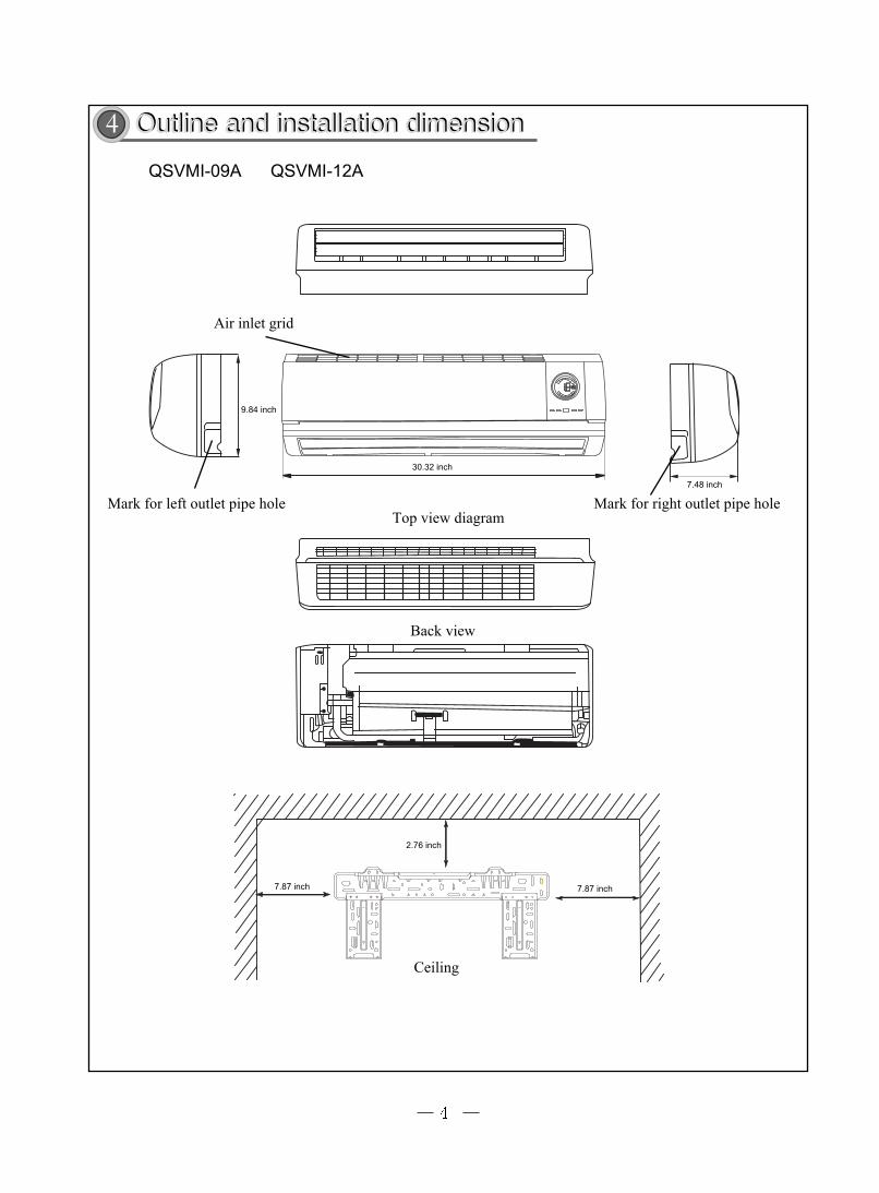
4 Outline and installation dimensionOutline and installation dimension
QSVMI-09A QSVMI-12A
9.84 inch
30.32 inch
7.48 inch
7.87 inch
2.76 inch
7.87 inch

Air inlet grid
Mark for left outlet pipe hole Top view diagram Mark for right outlet pipe hole
Back view
Ceiling
QSVMI-18A
11.22 inch
32.68 inch7.87 inch
7.87 inch
2.76 inch
7.87 inch

Electrical circuit diagramElectrical circuit diagram55555
These circuit diagrams are subject to change without notice, please refer to the one supplied with the unit.
QSVMI-09A QSVMI-12A
QSVMI-18A
66666
� �
� �
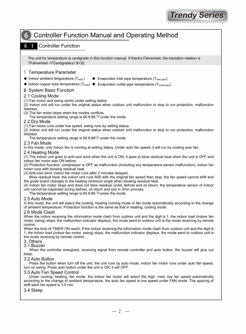
Controller Function Manual and Operating MethodController Function
The unit for temperature is centigrade in this function manual. If there's Fahrenheit, the transition relation is TFahrenheit =TCentigrade 1.8+32.
Temperature ParameterIndoor ambient temperature (Tamb.) Indoor copper tube temperature (Ttube)
Evaporator inlet pipe temperature (Tinlet pipe) Evaporator outlet pipe temperature (Toutlet pipe)
System Basic Function2.1 Cooling Mode
(1) Fan motor and swing works under setting status (2) Indoor unit will run under the original status when outdoor unit malfunction or stop to run protection, malfunction displays. (3) The fan motor stops when the modes conflicts. The temperature setting range is 60.8-86 under the mode. 2.2 Dry Mode (1) Fan motor runs under low speed, swing runs by setting status. (2) Indoor unit will run under the original status when outdoor unit malfunction or stop to run protection, malfunction displays. The temperature setting range is 60.8-86 under the mode.
2.3 Fan Mode In this mode, only indoor fan is running at setting status. Under auto fan speed, it will run by cooling auto fan.
2.4 Heating Mode (1) The indoor unit goes to anti-cool wind when the unit is ON; it goes to blow residual heat when the unit is OFF and
indoor fan motor was ON before. (2) Protection function, compressor is OFF as malfunction (including any temperature sensor malfunction), indoor fan
motor runs with blowing residual heat. (3) Anti-cool wind: indoor fan motor runs after 2 minutes delayed. Blow residual heat: the indoor unit runs 60S with the original fan speed then stop; the fan speed cannot shift and
the guide board changes to the heating minimum angle when blowing residual heat. (4) Indoor fan motor stops and does not blow residual under defrost and oil return; the temperature sensor of indoor
unit cannot be inspected during defrost, oil return and exit in 3min process. The temperature setting range is 60.8-86 under the mode. 2.5 Auto Mode In this mode, the unit will select the cooling, heating running mode or fan mode automatically according to the change
of ambient temperature. Protection function is the same as that in heating, cooling mode. 2.6 Mode Clash
When the indoor receiving the information mode clash from outdoor unit and the digit is 1, the indoor load (indoor fan motor, swing) stops, the malfunction indicator displays, the mode send to outdoor unit is the mode receiving by remote
control. When the time of TIMER ON reach, if the indoor receiving the information mode clash from outdoor unit and the digit is 1, the indoor load (indoor fan motor, swing) stops, the malfunction indicator displays, the mode send to outdoor unit is the mode receiving by remote control.
3. Others 3.1 Buzzer When the controller energized, receiving signal from remote controller and auto button, the buzzer will give out
beep. 3.2 Auto Button
Press the button when turn off the unit, the unit runs by auto mode, indoor fan motor runs under auto fan speed, turn on swing. Press auto button under the unit is ON, it will OFF.
3.3 Auto Fan Speed Control Under cooling, heating, fan mode, the indoor fan motor will select the high, med, low fan speed automatically according to the change of ambient temperature, the auto fan speed is low speed under FAN mode. The spacing of
shift each fan speed is 3.5 min. 3.4 Sleep
OF
OF
OF

In cooling and fan mode, after setting sleep procedure 1h, Tpreset will increase 33.8 ; 2h later, Tpreset will increase 35.6 , then remain the temperature, Tpreset will not exceed 86 ; under heating, after setting sleep procedure 1h, Tpreset will decrease 33.8 ; 2h later, Tpreset will decrease 35.6 , then remain the temperature, Tpreset will not exceed 60.8 ; the setting temperature will not change under fan and auto mode. 3.5 TIMER Function General timer:
a. TIMER ON: The timer on can be set when the unit is OFF, the controller will run under original setting mode when the time of timer on reaches, the timer space is 0.5h, and setting range is 0.5-24h.
b. TIMER OFF: The timer off can be set when the unit is ON, the unit is OFF when the timer time reaches, the timer space is 0.5h, and setting range is 0.5-24h.
Clock timer:
a. TIMER ON: If set timer on when the unit is running, it will goes to run; if set the timer on when the unit is off, the unit will run with the pre-setting mode when the time of setting timer on reaches.
b. TIMER OFF: If set timer off when the unit is off, when setting timer off, the unit will maintain stand-by status; if set timer off when the unit is on, when the time of setting timer off reaches, the system will stop to run.
c. TIMER changing: When the unit under timer status, it can set ON and OFF by remote control, and reset timer time, the unit will run under the last setting status.
Set timer on and timer off together when the unit is running, the unit will maintain the current status, once the time of setting timer off reaches, the unit will stop to work. Set timer on and timer off together when the unit is off, the unit will maintain off status until the time of timer on reaches, the unit will start to work, hereafter the time of timer on reaches everyday, the unit will run under the original setting mode, and the unit stop to work when the time of timer off reaches. When the time of setting timer on and setting timer off is the same, the unit is off.
3.6 Memory Function Memory contents: mode, swing (up and down), light, set Temp., set fan speed, general timer (clock timer doesn’t memory) The unit will on automatically with memory content after re-energized. There is no setting timer function in the last remote control order, and the system memory the last remote control order and working under that setting method. There is general timer function in the last remote control order, the system is energized before the timer time haven’t reach, the unit will memory timer function of the last remote control order after re-energized, and the timer time will star to calculate after re-energized. There is timer function in the last remote control order, but the timer time reaches, the system will de-energize after timer on and timer off, after re-energized, the system will memory the running status which before power-off, and no timer action; the clock timer doesn’t memory. 3.7 I FEEL Function If controller receives I FEEL command, it will run at the ambient temp sent by remote controller (but it will also run at sampling temp. of AC temp sensor itself except defrost and anti-cool air). The remote controller will send ambient temp to controller every 10min, so if the controller hasn’t received ambient temp from remote controller after 11min, it will run at temp. of AC itself. If this function is not set, all ambient temp will adopt sampling value of AC temp. sensor itself. 3.8 Turbo Function The TURBO function can be set only under COOLING and HEATING mode, when controller receiving turbo order, the indoor fan motor will run with high speed, and send turbo signal and high speed to outdoor unit. 3.9 Swing (up and down) Control After energization, up & down swing motor will totate guide louver to position 0 to close air outlet. After turn on the unit,if swing function has not been set, up & down guide louver will clockwise turn to position D under heating mode, or clockwise turn to level position L1 under other modes. If the unit is turn on with swing function setting, guide louver will swing between L and D. There are 7 kindsof swing states of guide louver. Position L,A,B,C,D, swing between L and D, stopbetween L and D (included angle L and D is equiangular). Upon stop of unit, guidelouver will close to position 0. Swing action is valid only when swing command isset and indoor fan is running.
° °
Heating Angle Cooling Angle
3.10 Cold Plasm FunctionRemote control the cold plasm function to ON and turn on the cold plasm when thefan motor is ON; remote control the cold plasm to OFF or turn off the cold plasm when the dan motor is OFF.
OF
OF OF
OFOF OF

4. Display4.1 Basic Display (1) When the unit is energized, the display symbol display, then only power lamp is light. (2) When use remote control to turn on the unit, the running LED is light, and the current setting running mode lamp displayed at the same time. COOLING: running lamp and cooling lamp are light; HEATING: running lamp and heating lamp are light; DRY: running lamp and dry lamp are light; FAN: running lamp and fan lamp are light; AUTO: auto lamp, running lamp and actual running mode lamp are light. (3) If turn off the LIGHT button, all the display is off (it is valid when the unit is OFF). (4) After set SLEEP function, the display maintains the original display status, it means the light switch does not influence sleep function. 4.2 Dual-8 Display If the digital pipe display current setting temperature, the setting temperature range is 60.8-86 . It will display 77 for cooling and fan under auto mode, and display 68 for heating, and the cooling controller displays 77 . The temperature range is 32-140 when the indoor temperature displays. 4.3 Fan Speed Display There are 3 status dynamic circle display for fan symbol, they are middle two segments, middle four segments and display six segments, and the middle two segments is displaying. The fan speed symbol blinks the fastest when remote control super-fan; the fan speed symbol blinks the lowest when remote control low-fan; the blink speed of display symbol is between high fan and low fan when remote control med fan; the blink speed of display depends on the indoor actual running speed when remote control auto fan speed; if the indoor fan motor stops, it blink display at the lowest speed. 4.4 Indoor unit Malfunction Lamp Display
Mal Malfunction Name Dual-8 Display
Running Lamp
Heating Lamp
Cooling Lamp
The system is abnormal (anti-high temp. power off, cooling overload)
H4
Blink 4 times
Compressor overload protection H3 Blink 3 times Module protection H5 Blink 5 times High-pressure protection E1 Blink once Anti-freeze protection power-off E2 Blink Twice Discharge temperature protection E4 Blink 4 times Low voltage over-current protection E5 Blink 5 times Mode Clash E7 Blink 7 times Communication malfunction E6 Blink 6 times Defrost or heating oil return H1 Blink once The indoor ambient temperature sensor is open, short circuit
F1 Blink once
Any indoor evaporator temperature sensor is open, short circuit
F2 Blink twice
The outdoor ambient temperature sensor is open, short circuit
F3 Blink 3 times
The outdoor condenser temperature sensor is open, short circuit
F4 Blink 4 times
The outdoor discharge temperature sensor is open, short circuit
F5 Blink 5 times
Fail to start up H7 Blink 7 times PFC malfunction HC Blink 6 times Compressor demagnetizing protection HE Blink 14 times The malfunction below need used by remote controller, it will display when press sleep button 6 times continuously in 3S, and exit inspect state(it is not valid under auto mode) automatically in 5min, or will exit when press sleep button 6 times continuously in 3S. Cooling overload down frequency F6 Blink 6 timesUnit overflow down frequency F8 Blink 8 timesCompressor discharge down frequency F9 Blink 9 timesUnit AC voltage decreasing down frequency E0 Blink 10 times Heating anti-high temperature down frequency H0 Blink 10 times Anti-cool air protection E9 Blink 9 times Cooling oil return F7 Blink 7 times
Note: The malfunction code will circular display when different malfunctions exist together. The indicator will light 0.5S and display 0.5S when it blinks. The indoor temperature sensor malfunction will not inspected under defrost, oil return.
OF OFOF OF
OF
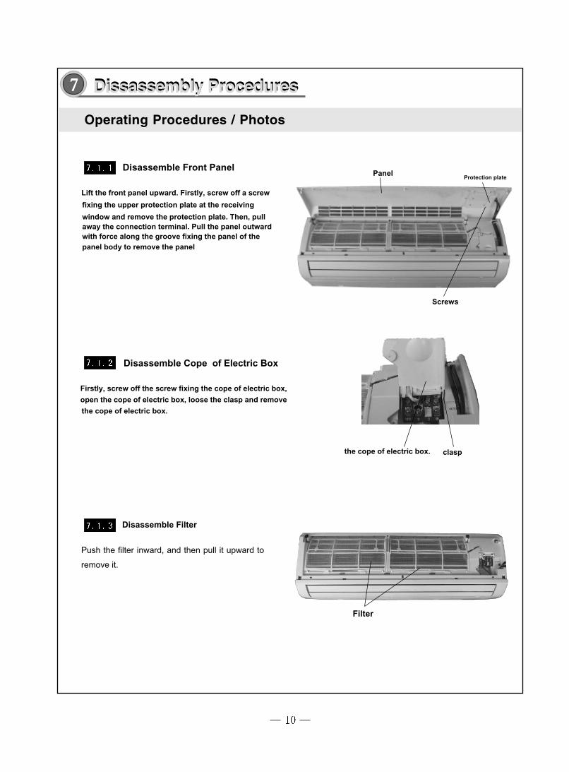
Disassemble Front Panel
Lift the front panel upward. Firstly, screw off a screw
fixing the upper protection plate at the receiving
window and remove the protection plate. Then, pull away the connection terminal. Pull the panel outward with force along the groove fixing the panel of the panel body to remove the panel
Disassemble Cope of Electric Box
Firstly, screw off the screw fixing the cope of electric box,
open the cope of electric box, loose the clasp and remove
the cope of electric box.
Disassemble Filter
Push the filter inward, and then pull it upward to
remove it.
Protection platePanel
the cope of electric box. clasp
Filter
Screws
Dissassembly ProceduresDissassembly Procedures77777
Operating Procedures / Photos

Disassemble Lower Guide Louver
Manually bend the lower guide louver to loose the clasp at the guide louver. Remove the lower guide louver.(Note:to remove the upper guide louver,you
must open the front case first, then screw off the screws fixing the upper guide louver and the water tray , bend
the upper guide louver and remove the upper guide louver) Guide Louver clasp
Disassemble Front Case
Unscrew the three screw covers at the front case, unscrew the three screws, pull open the clasp at the front case, and remove the front case.
clasp
sensor
screw covers screws
Disassemble Water Tray
Screw off the fixing screws fixing the water tray with a
screw driver. Loose the clasp at the other end and pull out the terminal board of the step motor. Pull upward
the water tray and take it out. Remove the water tray.
Water Tray
Operating Procedures / Photos

Operating Procedures / Photos
Loosen the three clasps, and pull upward to
remove the cover of the electric box.
Disassemble Cover of Electric Box
cover of the electric boxclasp
Disassemble Electric Box
Remove the grounding wire of the evaporator. Take out the pipe temp. sensor. Unplug the plugging connector of the indoor motorat the electric box, use screwdriver to
unscrew the screw fixing the electric box, loose the clasp and remove the electric box.
pipe temp. sensor room sensor
grounding wire
plugging connector clasp
screw
Disassemble Evaporator
rear pipe clamp
screw
Screw off one screw which fix the connection
board clamp.Take down the connection board
clamp.
Screw off 4 screws fixing the left and right side of
the evaporator, then elevate left side the evapora-
tor to remove it backward.
CAUTION:When repair, Carefully take out the evaporator and
pay attention to protect the connecting pipe.

Operating Procedures / Photos
Evaporator
claspscrew
screw
Evaporator
Disassemble Motor
Use screwdriver to unscrew the two screws fixing the motor clamp, and remove the motor clamp. Unscrew the three holding screws at the shaft sleeve, and remove the motor.
motor clamp
Screw
screw
MotorAxial fan

Disassemble Cross Flow Fan
After remove the motor, pull out it from the
left bearing holder.
Cross Flow Fan
Bearing Holder
Operating Procedures / Photos

8 Explosive view and spare parts listExplosive view and spare parts list
Exploded View of Component 1

1 Wall-Mounting Frame 12 Rear Case 13 Evaporator Assy 14 Cross Flow Fan 15 Ring of Bearing 16 / /7 Drainage Pipe 18 Water Tray 19 Swing Louver 12
10 Swing Linkage 1 111 Swing Linkage 2 112 Front Case 113 Front Panel 114 Decorate piece 115 Remote control YT1F 116 Filter 217 Receiver Board D5K3 118 Screw Cover 319 Guide Louver 1 120 Guide Louver 2 121 Motor MP28VB 122 Motor Clamp 123 Motor FN14P-PG 124 Electric box cover 125 Covering plate 126 Terminal board T4B3A 127 Electric box 128 Main PCB MB803F2AJ 129 Room Sensor15K 1
111
31 Jumping Connector 132 Transformer 48X26P 133 Wire clamp 134 Rear clamp 135 Connecting Cable 136 swing louver clamp 137 swing louver 138 swing louver(up) 139 swing louver(down) 1
QtyPart Code
30 Tube Sensor 20K
No DescriptionQSVMI-09A012522202220200160100205341035200176512203
/0523001401201820270105120881058200210582003200022107
200022092C68012019305100491112005113054504124252006210512033210512034215012086261120141501207632012208220112058420112332011205730038004390000451
3900019814390001981539000198164202300102
43110293
105824081054200410542005
7101010324242001
/10582409
Components and Parts List 1
The above data are subject to be changed without notice.
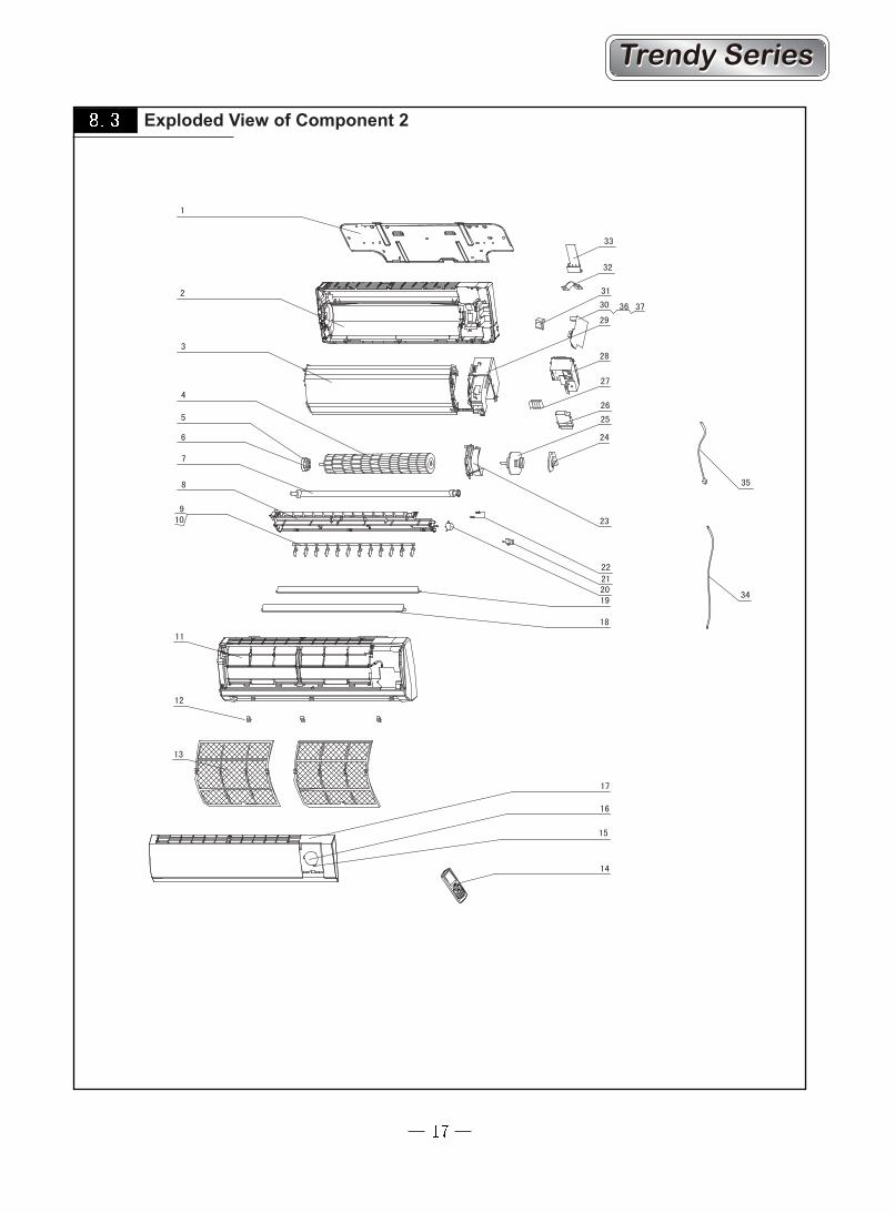
Exploded View of Component 2

Part CodeQSVMI-12A
1 Wall-Mounting Frame 01252384 12 Rear Case 222020503 13 Evaporator Assy 01002250 14 Cross Flow Fan 10352005 15 Ring of Bearing 76712015 16 \ \ \7 Drainage Pipe 0523001401 18 Water Tray 201820306 19 Swing Louver 105120413 1210 Swing Linkage 105824397 111 Front Case `200022958 112 Screw Cover 242520072 313 Filter 11122440 214 Remote Control YT1F 30510049 115 Decorate Piece 68012019 116 Receiver Board 30545042 117 Front Panel 200022921 118 Guide Louver 261120432 119 Guide Louver 261120422 120 Motor MP28EC 15212002 121 \ \ \22 \ \ \23 Right Motor Clamp 26112429 124 Bearing Holder 26152423 125 Motor FN20M-PG 150120873 126 Electric Box Cover 20122081 127 Terminal Board T4B3A 42011233 128 Covering Plate 20112060 129 Electric Box 20112059 130 Main PCB M803F2AJ 30038004 131 Transformer 48X26P 43110293 132 Wire Clamp 71010003 133 Rear Clamp 26112430 134 Connecting Cable 400204056 135 \ \ \36 Room Sensor 15K 390000451 1
3900019814 13900019815 13900019816 1
37 Tube Sensor 20K
No Description Qty
Components and Parts List 2
The above data are subject to be changed without notice.

Exploded View of Component 3

Part CodeQSVMI-18A
1 Wall-Mounting Frame 01252004 12 Rear Case 22202329 13 Fan Bearing 76512203 14 Screw Cover 24252015 35 Swing Louverb 105120472 115 Swing Louver 10512430 16 Swing Link 1 10582057 17 Swing Link 2 10582058 18 Water Tray 20182057 19 Guide Louver(up) 10512085 110 Guide Louver(down) 10512086 111 Cross Flow Fan 10352022 112 Evaporator Assy 01002913 113 Drainage Pipe 05230014 114 Evaporator Support 24212067 115 Filter 11122048 216 Front Case 200026524 117 Front Panel 2000284402 118 Remote Controller YT1F 30510049 119 Displaying Light Board 22432071 120 Electric Box Cover 1 20112019 121 Wire Clamp 71010103 122 Terminal Board (3位) 4201026601 123 Electric Box Cover 20112020 124 Main PCB 30038022 125 Transformer 57X25F 43110257 126 Room Sensor 15k 390001912 1
3900019814 13900019815 13900019816 1
28 Sensor Insert 42020063 329 Electric Box 20112018 130 Lower Shield of Electric Box 01592037 131 Upper Shield of Electric Box 01592038 132 Stepping Motor MP35XX 15213001 133 Motor Clamp 26112095 134 Helicoid tongue 26252009 135 Motor FN20K-PG 15012718 136 Pipe Clamp 24242001 137 Connecting Cable / 138 Plank Cable 4003004201 139 Jumping Connector 4202300106 1
No Description Qty
27 Tube Sensor 20k
Components and Parts List 3
The above data are subject to be changed without notice.


QUIETSIDE CORPORATION www.quietside.com
West Office 8750 Pioneer Blvd. Santa Fe Springs, CA 90670 USA Phone: 562-699-6066 Fax: 562-699-4351
East Office 6 Pine Hill Drive Carlisle, PA 17013 Phone: 886-243-6498/ 717-243-2535 Fax: 717-243-7917
TX Office 3001 Northern Cross Blvd. Suite 361 Fort Worth, TX 76137 Phone: 817-838-6066 Fax: 817-838-8670
66129908658