HYDRAULICS OF SLOPE-TAPERED PIPE CULVERTS · Culverts, culvert design coefficients, inlet control,...
105
Hydraulics of Iowa DOT Slope-Tapered Pipe Culverts FHWA-RD-01-077 JUNE 2001 Research, Development, and Technology Turner-Fairbank Highway Research Center 6300 Georgetown Pike McLean, VA 22101-2296
Transcript of HYDRAULICS OF SLOPE-TAPERED PIPE CULVERTS · Culverts, culvert design coefficients, inlet control,...

Hydraulics of Iowa DOT Slope-TaperedPipe CulvertsFHWA-RD-01-077 JUNE 2001
Research, Development, and TechnologyTurner-Fairbank Highway Research Center6300 Georgetown PikeMcLean, VA 22101-2296
HRTS
Visit the TFHRC website at www.tfhrc.gov/
FOREWORD
This report documents a laboratory study that was done for the Iowa DOD to evaluate the hydraulic characteristics of a special improved pipe inlet culvert comprised of off-the-shelf precast components. This report is primarily of interest to the Iowa DOT but will be of interest to drainage engineers in general who would like to consider unique culvert designs to improve performance. This report is being distributed as a web document only as a laboratory report from the TFHRC hydraulic laboratory.
T. Paul Teng, P.E. Director, Office of Infrastructure Research and Development
NOTICE
This document is disseminated under the sponsorship of the Department of Transportation in the interest of information exchange. The United States Government assumes no liability for its contents or use thereof. this report does not constitute a standard, specification, or regulation. The United States Government does not endorse products or manufacturers. Trade and manufacturers’ names appear in this report only because they are considered essential to the object of the document.

Technical Report Documentation Page 1. Report No. FHWA-RD-01-0077
2. Government Accession No. 3. Recipient's Catalog No.
4. Title and Subtitle HYDRAULICS OF SLOPE-TAPERED PIPE CULVERTS
5. Report Date
6. Performing Organization Code
8. Performing Organization Report No. 7. Author(s) Frank Graziano, Stuart Stein, Ed Umbrell, and Brett Martin
9. Performing Organization Name and Address GKY and Associates, Inc. 5411-E Backlick Road Springfield, VA 22151
10. Work Unit No. (TRAIS)
11. Contract or Grant No. DTFH61-95-C-00066
13. Type of Report and Period Covered
Final Report 1996-1998
12. Sponsoring Agency Name and Address Office of Infrastructure Research and Development Federal Highway Administration 6300 Georgetown Pike McLean, VA 22101-2296
14. Sponsoring Agency Code
15. Supplementary Notes Contracting Officer’s Technical Representative (COTR): J. Sterling Jones, HRDI
16. Abstract This report updates the Iowa Department of Transportation (DOT) design procedures for circular, slope-tapered concrete culverts. The current practice is to use the design coefficients for a square-edged, circular concrete culvert with a headwall that are found in Hydraulic Series No. 5 (HDS-5). New inlet control design constants and entrance loss coefficients were calculated for the slope-tapered culverts and then compared with the HDS-5 coefficients (square edge). In addition, various reducer lengths and taper ratios were also studied to determine what impact, if any, they have on the design coefficients. All of the laboratory testing was done at the Federal Highway Administration’s Turner-Fairbank Highway Research Center located in McLean, Virginia.
17. Key Words Culverts, culvert design coefficients, inlet control, outlet control, hydraulic design
18. Distribution Statement No restrictions. This document is available to the public through the National Technical Information Service, Springfield, VA 22161.
19. Security Classif. (of this report) Unclassified
20. Security Classif. (of this page) Unclassified
21. No. of Pages 103
22. Price
Form DOT F 1700.7 (8-72) Reproduction of completed page authorized

ii

iii
TABLE OF CONTENTS Page No.
1. INTRODUCTION.................................................................................................................... 1 2. EXPERIMENTAL SETUP...................................................................................................... 2 3. TEST MATRIX...................................................................................................................... 12 4. CULVERT ANALYSIS AND RESULTS............................................................................. 15 5. DISCUSSION OF RESULTS................................................................................................ 19 6. CONCLUSIONS.................................................................................................................... 20 7. ADDITIONAL STUDIES ..................................................................................................... 23 APPENDIX A. CALCULATING SPECIFIC HEAD AT CRITICAL DEPTH.......................... 35 APPENDIX B. LABORATORY DATA..................................................................................... 38

iv
LIST OF TABLES Page No.
Table 1. Iowa DOT guidelines..................................................................................................... 12 Table 2. Test matrix ..................................................................................................................... 13 Table 3. Inlet control design coefficients (English units) ............................................................ 16 Table 4. Outlet control design coefficients .................................................................................. 19 Table 5. Summary of inlet control design coefficients ................................................................ 21 Table 6. Summary of outlet control entrance loss coefficients (without friction losses) ............ 22 Table 7. Summary of coefficients for Iowa prefabricated inlet and square-edge inlet with
headwall ......................................................................................................................... 23
LIST OF FIGURES Page No.
Figure 1. Experimental setup ......................................................................................................... 2 Figure 2. Typical setup .................................................................................................................. 3 Figure 3. Inlet #13 – Prefabricated inlet scaled for a 48-in (1219-mm) inlet pipe. ....................... 4 Figure 4. Prefabricated inlet scaled for a 78-in (1981-mm) inlet pipe........................................... 5 Figure 5. 20-degree elbow. ............................................................................................................ 6 Figure 6. Reducers used for runs 10-14, scaled for 48-in (1219-mm) inlet pipe........................... 7 Figure 7. Reducers used for runs 1-5, scaled for 78-in (1981-mm) inlet....................................... 8 Figure 8. Reducers used for runs 6-8, scaled for 78-in (1981-mm) inlet....................................... 9 Figure 9. Reducers used for runs 15-17, scaled for 48-in (1219-mm) inlet................................. 10 Figure 10. Calculation of He,tot for outlet control runs .............................................................. 11 Figure 11. Comparison plot of the three unsubmerged benchmark inlets. .................................. 24 Figure 12. Comparison plot of the submerged benchmark inlets. ............................................... 25 Figure 13. Reducer length effect for D1/D2 = 11.5 / 8.625. ......................................................... 26 Figure 14. Reducer length effect for D1/D2 = 11.5 / 8.75. ........................................................... 27 Figure 15. Reducer length effect for D1/D2 = 11.5 / 9.5. ............................................................. 28 Figure 16. Reducer length effect for D1/D2 = 11.5 / 10.0. ........................................................... 29 Figure 17. Diameter reduction effect – One reducer. .................................................................. 30 Figure 18. Diameter reduction effect – Two reducers. ................................................................ 31 Figure 19. Diameter reduction effect – Three reducers. .............................................................. 32 Figure 20. Iowa DOT nomograph for calculating specific head. ................................................ 33 Figure 21. Comparison plot of Iowa DOT nomograph Hc versus calculated Hc.......................... 34 Figure 22. Geometric parameters for pipes flowing partially full. .............................................. 36

1
1. INTRODUCTION
The purpose of this research report is to update the Iowa Department of Transportation (DOT) design procedures for circular, slope-tapered concrete culverts. The current practice is to use the design coefficients for a square-edged, circular concrete culvert with a headwall that are found in Hydraulic Series No. 5 (HDS-5). New inlet control design constants and entrance loss coefficients were calculated for the slope-tapered culverts and were then compared with the HDS-5 coefficients (square edge). In addition, various reducer lengths and taper ratios were also studied to determine what impact, if any, they have on the design coefficients. All of the laboratory testing was done at the Federal Highway Administration’s Turner-Fairbank Highway Research Center located in McLean, Virginia.
2. EXPERIMENTAL SETUP
The experimental setup was constructed primarily of plywood and consisted of a 2.43-m-long by 2.43-m-wide headbox, and a 1.21-m-wide by 2.43-m-long tailbox, which was located 4.5 m downstream of the headbox. The slope-tapered inlet and culvert barrel spanned the 4.5 m between the headbox and the tailbox. The test matrix included two Iowa DOT precast culvert inlets, a 20-degree elbow, 11 reducers, and 4 different culvert barrel diameters. Prototype-to-model scaling ratios of 6.783 to 1.0 and 4.174 to 1.0 were used.
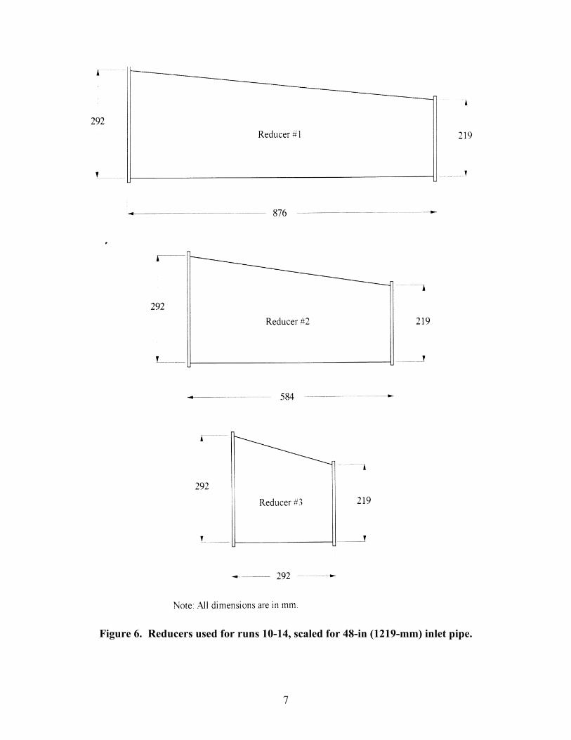
A sketch of the experimental setup is shown in figure 1. The elbows and culvert barrels were constructed of clear plexiglass. The two inlets and the reducers were fabricated out of galvanized sheet metal. For each test condition, an inlet was connected to the upstream end of the elbow and a reducer was attached to the downstream end. These three pieces formed the slope-tapered inlet. A 3.66-m-long pipe was attached to the downstream end of the reducer. A detailed drawing of the slope-tapered inlet is shown in figure 2. The dimensions for the two Iowa DOT precast inlets that were tested are shown in figures 3 and 4. The 20-degree elbow section is shown in figure 5. The 11 reducers that were tested are detailed in figures 6, 7, 8, and 9.
Fourteen pressure ports were inserted along the bottom of the culvert setup to measure hydraulic depth. These depths were measured using a pressure transducer and the Labtech Notebook software package. Two in-line electro-magnetic flow tubes measured the discharge.
Water entered the headbox through two inflow pipes and flowed over a broad-crested weir. This helped produce a uniform flow field and reduced the upstream velocity to virtually zero. The flow entered the culvert inlet, passed through the elbow, reducer, and barrel, and was discharged into the tailbox. The tailbox had an adjustable tailgate that created a backwater effect that was used to study the culverts under outlet control conditions.

2
Figu
re 1
. Ex
peri
men
tal s
etup
.
Hea
dbox
(hea
dwat
er)
Tailb
ox
(tai
lwat
er)

3
Figu
re 2
. T
ypic
al se
tup.

4
Figure 3. Inlet #13 – Prefabricated inlet scaled for a 48-in (1219-mm) inlet pipe.

5
Figure 4. Prefabricated inlet scaled for a 78-in (1981-mm) inlet pipe.

6
Figure 5. 20-degree elbow.
7
Figure 6. Reducers used for runs 10-14, scaled for 48-in (1219-mm) inlet pipe.

8
Figure 7. Reducers used for runs 1-5, scaled for 78-in (1981-mm) inlet.

9
Figure 8. Reducers used for runs 6-8, scaled for 78-in (1981-mm) inlet.

10
Figure 9. Reducers used for runs 15-17, scaled for 48-in (1219-mm) inlet.

11
Figu
re 1
0. C
alcu
latio
n of
He,
tot f
or o
utle
t con
trol
Ave
rage
Ene
rgy
Gra
de L
ine
(EG
L) in
Hea
dbox

12
3. TEST MATRIX
The Iowa DOT guidelines, as shown in table 1, include the specifications for: (1) allowable diameter (D) reductions from the inlet pipe to the main barrel pipe and (2) minimum barrel slopes required to maintain supercritical flow at 0.8*D with an assumed Manning roughness coefficient (n) value of 0.012 for various design discharges. Iowa DOT also recommends a 4.0-ft (1.2-m) reducer length for each 6.0-in- (152.4-mm-) diameter reduction. Table 2 shows the test matrix that was set up to recommend modifications to the Iowa DOT guidelines for slope-tapered pipe culverts.
Table 1. Iowa DOT guidelines. Diameter Reduction, inches Approximate Q,
ft3/s From To Minimum Barrel Slope,
% Equivalent Number
of Reducers
350 84 72 0.8 2
350 84 66 1.1 3
295 78 66 1.0 2
295 78 60 1.3 3
245 72 60 1.0 2
245 72 54 1.6 3
200 66 54 1.2 2
200 66 48 2.0 3
160 60 54 0.9 1
160 60 48 1.5 2
125 54 48 1.0 1
125 54 42 1.7 2
96 48 42 1.2 1
96 48 36 2.0 2
71 42 36 1.3 1
50 36 30 1.6 1
33 30 24 2.0 1
1 in = 25.4 mm, 1 ft3/s = 0.028 m3/s Note: Each reducer is 4.0 ft (1.2 m) in length. Therefore, three reducers would have a total length of 12.0 ft (3.6 m).

13
Table 2. Test matrix.
Q, (Discharge) Diameter Reduction, inches Reducers Test
Series
Run No.
Proto- type
(ft3/s)
Model (m3/s)
From
To
Barrel Slope,
% #
Length,
ft
Model No.
Model Length
(m) 1 35
2,26* 3,27 4,28
245 295 340 380
0.058 0.070 0.080 0.090
78" prototype
11.5" model
66" prototype
9.5"** model
0.5 1.0 1.5 2.0
2 8 5 5 5
0.360
2 5,29 1,25
295 0.070 78" prototype
11.5" model
66" prototype
9.5"** model
1.5 1 3
4 12
6 4
0.179 0.540
3 6,30 7,31 8,32
295 0.070 78" prototype
11.5" model
60" prototype 8.75"** model
2.0 1 2 3
4 8
12
7 8 9
0.179 0.360 0.540
4 bm1 bm2 bm5 bm6
295 0.070 78" prototype
11.5" model
78" prototype
11.5" model
3.5 5.0
- - - -
5 10,20 11,21 12,22 13,23
70 96
115 175
0.056 0.076 0.091 0.139
48" prototype
11.5" model
36" prototype
8.625" model
1.0 2.0 2.8 3.5
2 8 2 2 2 2
0.584
6 9,19 14,24
96
0.076
48" prototype
11.5" model
36" prototype
8.625" model
2.0 1 3
4 12
1 3
0.292 0.876
7 17,34 15,33
16
96 0.076 48" prototype
11.5" model
42" prototype
10.0" model
2.0
1 2
4 8
11 10 10
0.292 0.584
8 bm3 bm4 bm7 bm8
96 0.076 48" prototype
11.5" model
48" prototype
11.5" model
3.5 5.0
- - - -
1 in = 25.4 mm, 1 ft = 0.305 m, 1 ft3/s = 0.028 m3/s Notes: * The entries in bold reflect the Iowa DOT recommended design conditions for the diameter reductions.
** The Barrel diameters are not exact model sizes, but are the closest plexiglass tube sizes that were available commercially. Exact models would have been 9.73 in (247.1 mm) for the 66-in barrel and 8.846 in for the 60-in (1676.4-mm) barrel.

14
Series 1 and 5 were intended to verify the minimum slope criteria and to determine how performance was affected by discharges other than the design discharges outlined in the Iowa DOT guidelines. Series 2, 3, and 6 were intended to check the reducer length criteria. Series 4 and 7 were benchmark tests for the precast inlet by itself (without the bends and reducers) and were intended to derive new design coefficients to replace the HDS-5 chart 1, scale 1 (chart 1/1) coefficients that had been used previously for lack of better guidelines.
Another series of tests was conducted to model the HDS-5 chart 1/1 inlet, which is described as square edge with headwall for a circular concrete culvert. This series was performed primarily as a verification of the test procedures to determine if it was possible to duplicate the HDS-5 results.
Prototype-to-model scaling ratios were selected that would maximize the pumping capability of 5.0 ft3/s (0.14 m3/s) and minimize model fabrication costs. Standard 12-in- (304.8-mm-) diameter acrylic tubing was used to model both the 78-in (1981-mm)and the 48-in (1219-mm) inlet diameters. The inside diameter of the plexiglass tubing was actually 11.5 in (292.01 mm), which resulted in length scaling ratios (Lr) of 6.783 for the 78-in (1981-mm) inlet and 4.174 for the 48-in (1981-mm) inlet. Using the dimensionless Froude number as a scaling parameter, the following scaling ratios can be derived:
Lr = LengthPrototype/ LengthModel = 6.783 for the 78-in inlet = 4.174 for the 48-in inlet
Wr = wall thickness ratio = Lr
Qr = Qprototype /Qmodel = Lr2.5
= 119.8 for the 78-in inlet = 35.6 for the 48-in inlet
nr = nPrototype/nModel = Lr1/6
= 1.38 for the 78-in inlet = 1.27 for the 48-in inlet
The 5.0-ft3/s (0.14-m3/s) pump was capable of modeling 175 ft3/s (4.96 m3/s) for the 48-in (1219-mm) inlet and 600 ft3/s (16.99 m3/s) for the 78-in (1981-mm) inlet. It was not feasible to model Manning’s n, but it was measured for the model to document whether it was above or below the value assumed for the Iowa DOT guideline design table.
After the model was set up, it was relatively easy to run several discharges for each test series. Some of the slopes were deleted after it was determined when and where the shift from inlet control (presumed for the Iowa DOT guideline table) to outlet control occurred. In all, there were 18 runs where the culverts were operating under inlet control, 17 runs under outlet control, 8 benchmark runs for the precast inlets, and 4 runs for the special HDS-5 verification test.
15
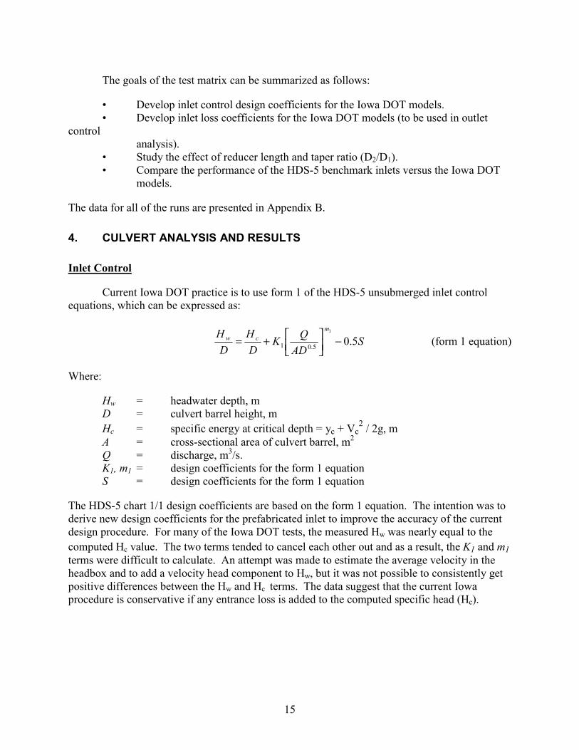
The goals of the test matrix can be summarized as follows:
• Develop inlet control design coefficients for the Iowa DOT models. • Develop inlet loss coefficients for the Iowa DOT models (to be used in outlet control analysis). • Study the effect of reducer length and taper ratio (D2/D1). • Compare the performance of the HDS-5 benchmark inlets versus the Iowa DOT models.
The data for all of the runs are presented in Appendix B.
4. CULVERT ANALYSIS AND RESULTS
Inlet Control
Current Iowa DOT practice is to use form 1 of the HDS-5 unsubmerged inlet control equations, which can be expressed as:
SAD
QKDH
DH m
cw 5.01
5.01 −
+= (form 1 equation)
Where:
Hw = headwater depth, m D = culvert barrel height, m Hc = specific energy at critical depth = yc + Vc
2 / 2g, m A = cross-sectional area of culvert barrel, m2 Q = discharge, m3/s. K1, m1 = design coefficients for the form 1 equation S = design coefficients for the form 1 equation
The HDS-5 chart 1/1 design coefficients are based on the form 1 equation. The intention was to derive new design coefficients for the prefabricated inlet to improve the accuracy of the current design procedure. For many of the Iowa DOT tests, the measured Hw was nearly equal to the computed Hc value. The two terms tended to cancel each other out and as a result, the K1 and m1 terms were difficult to calculate. An attempt was made to estimate the average velocity in the headbox and to add a velocity head component to Hw, but it was not possible to consistently get positive differences between the Hw and Hc terms. The data suggest that the current Iowa procedure is conservative if any entrance loss is added to the computed specific head (Hc).
16
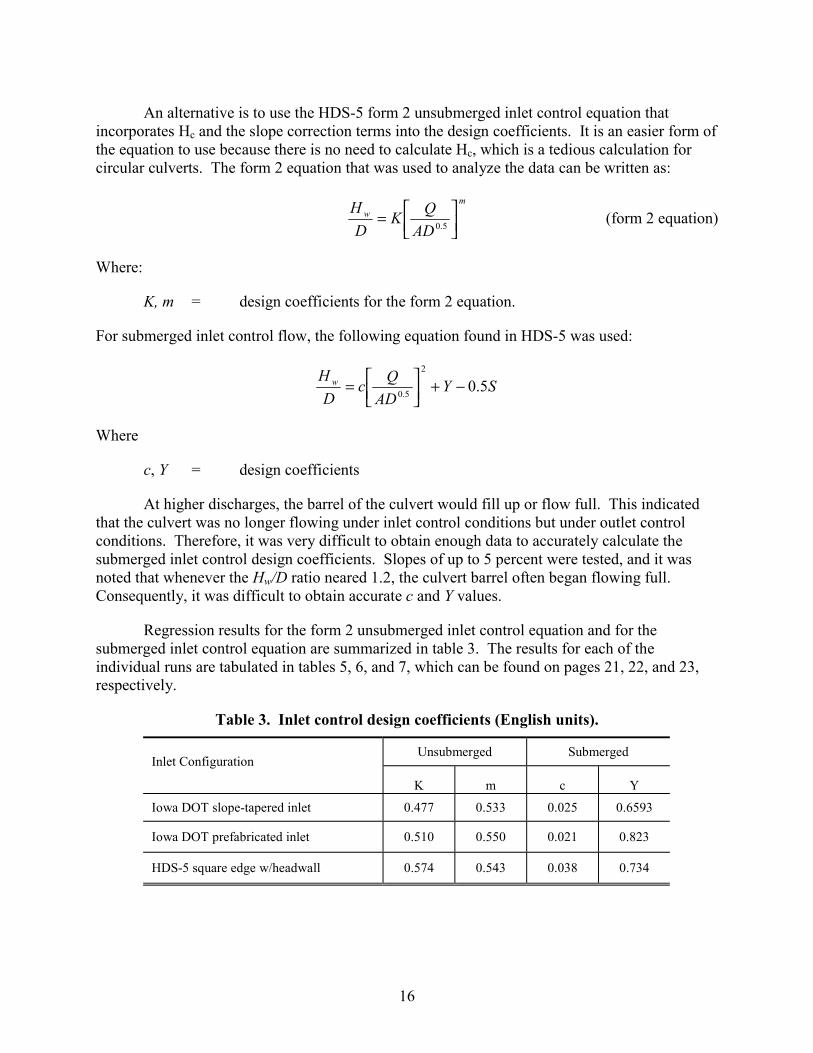
An alternative is to use the HDS-5 form 2 unsubmerged inlet control equation that incorporates Hc and the slope correction terms into the design coefficients. It is an easier form of the equation to use because there is no need to calculate Hc, which is a tedious calculation for circular culverts. The form 2 equation that was used to analyze the data can be written as:
m
w
ADQK
DH
= 5.0 (form 2 equation)
Where:
K, m = design coefficients for the form 2 equation.
For submerged inlet control flow, the following equation found in HDS-5 was used:
SYAD
QcD
H w 5.02
5.0 −+
=
Where
c, Y = design coefficients
At higher discharges, the barrel of the culvert would fill up or flow full. This indicated that the culvert was no longer flowing under inlet control conditions but under outlet control conditions. Therefore, it was very difficult to obtain enough data to accurately calculate the submerged inlet control design coefficients. Slopes of up to 5 percent were tested, and it was noted that whenever the Hw/D ratio neared 1.2, the culvert barrel often began flowing full. Consequently, it was difficult to obtain accurate c and Y values.
Regression results for the form 2 unsubmerged inlet control equation and for the submerged inlet control equation are summarized in table 3. The results for each of the individual runs are tabulated in tables 5, 6, and 7, which can be found on pages 21, 22, and 23, respectively.
Table 3. Inlet control design coefficients (English units).
Unsubmerged Submerged Inlet Configuration
K m c Y
Iowa DOT slope-tapered inlet 0.477 0.533 0.025 0.6593
Iowa DOT prefabricated inlet 0.510 0.550 0.021 0.823
HDS-5 square edge w/headwall 0.574 0.543 0.038 0.734

17
Note that the HDS-5 inlet control equations are not dimensionless throughout. The coefficients, listed in table 3 above are directly comparable with the HDS-5 coefficients. English units must be used for the table 3 coefficients to apply. The current version of HDS-5 coefficients, are applicable only if English units are used. One remedy would be to include the acceleration of gravity in the discharge intensity term to make it dimensionless, but that would change all of the coefficients that have the acceleration of gravity built into them. The conversion of coefficients from one system to the other is as follows:
m = exponent is the same for either system of units (English or SI metric) K = SI units = K (English units)*(0.3048)m/2 c = SI units = c (English units)*(0.3048) Y = constant is the same for either system of units
Outlet Control
When the culvert barrel begins to flow full, it is no longer just the inlet that exclusively governs the headwater depth. It is an accumulation of losses starting from the tailwater at the outlet, proceeding through the culvert barrel, and including the entrance losses at the inlet. Although a culvert flowing partially full could conceivably be in either inlet control or outlet control, a culvert flowing completely full throughout must be in outlet control. For many of the experiments involving the Iowa DOT slope-tapered inlets, the culvert barrel did fill up at the higher discharges, even when the barrel had a free outfall, i.e., no tailwater. Therefore, it was considered useful to document the entrance loss coefficients for outlet control as part of this study. For outlet control, the energy loss is expressed as a simple entrance loss coefficient (ke) multiplied by the culvert (or pipe) barrel velocity head to determine the energy loss through the entrance. This coefficient is dimensionless, is independent of the system of units, and is usually taken to be constant for a particular inlet. The experimental values varied slightly, but the highest values measured were reported for design purposes. The procedures used to determine the ke values are documented within this section.
The total entrance loss (Hetot) was measured for outlet control tests by projecting the energy grade line (EGL) in the headbox and the EGL for the culvert barrel to a common plane at the upstream end of the culvert barrel, as illustrated in figure 10. It was felt that there was enough overall length in the inlet to warrant rating the friction component separately from the minor losses attributed to the converging flows in the entrances, the flow direction changes in the bends, and the flow contraction in the reducer.

18
Then,
ebrefetot HHH +=
elbowelb
elb
reduceravg
avgef R
LVnR
LVnH
+
3/4
22
3/4
22
=
gVkH b
eebr 2
2
)()( calculatedefmeasuredetotebr HHH −=
Where:
Hef = friction losses in the reducer and elbow configuration, m Hebr = minor losses, other than friction, for the overall inlet, m ke = outlet control, entrance loss coefficient n = Manning’s roughness coefficient, which was determined to be approximately 0.010 for the plexiglass pipes used in the experiments Vavg = velocity in the reducer, m/s Velb = velocity in the elbow, m/s Vb = velocity in the culvert barrel, m/s Ravg = hydraulic radius for the reducer, m Relb = hydraulic radius for the elbow, m
The important thing to note is that the ke value reported does not include friction in the overall inlet, which could be more than 20 ft (6.1 m) long in the full-scale installation. For a circular pipe flowing full, R = D/4.
Manning’s n can be backcalculated by measuring the friction slope in the main culvert barrel for several full-flow tests and substituting it into the formula:
VSR
n f2/13/2
=
Where:
Sf = friction slope, which can be measured by the slope of the EGL, m
The calculated n values averaged 0.010, which is a reasonable value for the plexiglass piping. It was not possible to do the same for the reducers, which were fabricated from sheet metal, but it was assumed that the roughness of the metal was close enough to the plexiglass to use the 0.010 value throughout.

19
Table 4. Outlet control design coefficients.
Inlet Configuration ke
Iowa DOT slope-tapered inlet = 0.477 0.20
Iowa DOT prefabricated inlet = 27.2 0.35
HDS-5 square edge w/headwall = 0.574 0.50
Figures 11 and 12 compare the unsubmerged and the submerged laboratory data for the Iowa DOT prefabricated inlet, the square-edge headwall inlet, and the HDS-5 chart 1/1 coefficients. The laboratory results for the square-edge headwall correspond well with the HDS-5 coefficients. The figures also show that the Iowa DOT prefabricated inlet is more efficient than the other two inlets. The results for each of the individual runs are shown in tables 5, 6, and 7, which can be found on pages 21 through 23, respectively.
5. DISCUSSION OF RESULTS
The design coefficients and ke values listed in tables 3 and 4 would allow one to design the Iowa slope-tapered pipe culverts for a full range of discharges. Figures 11 and 12 show that the prefabricated inlet is more efficient than the HDS-5 chart 1/1 inlet. Iowa DOT had been using the HDS-5 inlet to represent both the unsubmerged and the submerged inlet control conditions. These figures also verify that the test procedures used in this study are consistent with previous research done for HDS-5.
Figures 13 through 16 show whether there is any advantage to using multiple reducer lengths to go from a large-diameter pipe to a smaller one. Figure 13 shows that there is no discernable advantage to using more than one reducer length for the 48-in- to 36-in- (1219-mm- to 914-mm-) diameter reduction at the design discharge, which was modeled using 0.076 m3/s. The Iowa DOT guideline is for two reducer lengths. Figure 14 shows some improvement by using two reducer lengths, but no additional improvement by using three reducer lengths for the 78-in- to 60-in- (1981-mm- to 1524-mm-) diameter reduction at the design discharge, which was modeled at 0.070 m3/s. Current Iowa DOT guidelines call for three reducer lengths at this discharge. Figure 15 seems to show a slight improvement by using two reducer lengths. However, the figure shows that there is no improvement by using three reducer lengths for the 78-in- to 66-in- (1981-mm- to 1676-mm-) diameter reduction. The Iowa DOT guideline is two reducer lengths. Figure 16 shows no improvement by using two reducer lengths rather than one for the 48-in- to 42-in- (1219-mm- to 1067-mm-) diameter reduction. The Iowa DOT guideline is for one reducer. Based on these observations, it appears that the number of reducers recommended by Iowa DOT is slightly conservative, usually by one reducer.

20
6. CONCLUSIONS
Iowa DOT should use form 2 of the unsubmerged inlet control design equations found in HDS-5. Examination of the procedures for calculating Hc showed them to be valid. However, for slope-tapered inlets, form 2 of the unsubmerged inlet control equations works better.
The taper ratio and the number of reducers do not seem to affect the energy losses through the slope-tapered inlets, nor do they seem to affect the transition between inlet control and outlet control for smaller culvert slopes. Tables 5, 6, and 7 summarize the design and entrance loss coefficients. Note that the friction losses must be calculated and added to the He values to yield the total head losses for each inlet.

Table 5. Summary of inlet control design coefficients.
Pipe Diameter = 9.5 inches Pipe Diameter = 8.75 inches
Reducer #6 Reducer #5 Reducer #4 Reducer #7 Reducer #8 Reducer #97.0625 inches 14.1875 inches 21.25 inches 7.0625 inches 14.1875 inches 21.25 inches
0.50% 0.50%slope slope
1.00% K = 0.479 1.00%slope m = 0.549 slope
1.50% K = 0.477 K = 0.487 K = 0.506 1.50%slope m = 0.539 m = 0.524 m = 0.499 slope
2.00% K = 0.458 2.00% K = 0.480 K = 0.488 K = 0.461slope m = 0.557 slope m = 0.527 m = 0.525 m = 0.556
Pipe Diameter = 8.625 inches Pipe Diameter = 10.0 inches
Reducer #3 Reducer #2 Reducer #1 Reducer #11 Reducer #1011.5 inches 23.0 inches 34.5 inches 11.5 inches 23.0 inches
1.00% K = 0.460 1.00%slope m = 0.531 slope
2.00% K = 0.475 2.00% K = 0.482 K = 0.481slope m = 0.506 slope m = 0.529 m = 0.535
2.80% K = 0.479 K = 0.470 K = 0.480 2.80%slope m = 0.521 m = 0.538 m = 0.531 slope
3.50% K = 0.474 3.50%slope m = 0.529 slope
21

Table 6. Summary of outlet control entrance loss coefficients (without friction losses).
Pipe Diameter = 9.5 inches Pipe Diameter = 8.75 inches
Reducer #6 Reducer #5 Reducer #4 Reducer #7 Reducer #8 Reducer #97.0625 inches 14.1875 inches 21.25 inches 7.0625 inches 14.1875 inches 21.25 inches
0.50% 0.50%slope slope
1.00% He = 6.44 1.00%slope Ke = 0.12 slope
1.50% He = 14.69 He = 9.92 He = 13.66 1.50%slope Ke = 0.13 Ke = 0.12 Ke = 0.12 slope
2.00% He = 10.49 2.00% He = 20.33 He = 31.52 He = 21.00slope Ke = 0.12 slope Ke = 0.15 Ke = 0.16 Ke = 0.15
Pipe Diameter = 8.625 inches Pipe Diameter = 10.0 inches
Reducer #3 Reducer #2 Reducer #1 Reducer #11 Reducer #1011.5 inches 23.0 inches 34.5 inches 11.5 inches 23.0 inches
1.00% He = 19.05 1.00%slope Ke = 0.13 slope
2.00% He = 19.37 2.00% He = 20.19 He = 8.76slope Ke = 0.14 slope Ke = 0.23 Ke = 0.22
2.80% He = 21.04 He = 20.09 He = 19.76 2.80%slope Ke = 0.13 Ke = 0.14 Ke = 0.13 slope
3.50% He = 20.36 3.50%slope Ke = 0.14 slope
22

23
Table 7. Summary of coefficients for Iowa prefabricated inlet and square-edge inlet with headwall.
Inlet Control
Prefab Inlet #12 Prefab Inlet #13 Square-edge with Headwall
3.50% K = 0.510 K = 0.490 K = 0.574slope m = 0.560 m = 0.560 m = 0.543
5.00% K = 0.540 K = 0.500slope m = 0.520 m = 0.560
Outlet Control
Prefab Inlet #12 Prefab Inlet #13 Square-edge with Headwall
3.50% He = 30.0 He = 26.0 He = 44.6slope Ke = 0.38 Ke = 0.33 Ke = 0.56
5.00% He = 28.5 He = 24.4slope Ke = 0.36 Ke = 0.31
7. ADDITIONAL STUDIES
The following is a list of future studies that Iowa DOT may wish to consider that could address outstanding technical issues:
Test the slope-tapered inlets without the reducers in order to isolate the head losses associated with just the reducers.
Test additional slopes for the inlet control runs. The culvert barrel was often filling up when Hw/D neared 1.2. Submerged inlet coefficients could be calculated with the additional data.
Perform more detailed inlet control tests that determine exactly where the flow translates from inlet control to outlet control. The effect of the number of reducers can also be examined to see if it has any effect on where the transition from inlet control to outlet control occurs.

Inlet Control - Unsubmerged
0.00
0.25
0.50
0.75
1.00
1.25
1.50
0.00 0.50 1.00 1.50 2.00 2.50 3.00 3.50 4.00
Q / AD0.5
Hw
/ D
Iowa Prefab Inlet (Regression Curve) Lab Chart 1/1 (from this Regression)Iowa Prefab Data Point Lab Chart 1/1 Data PointHDS-5 Chart 1/1 (from HDS-5 Equation)
Figure 11. Comparison plot of the three unsubmerged benchmark inlets.
24

Inlet Control - Submerged
0.00
0.50
1.00
1.50
2.00
2.50
5.00 10.00 15.00 20.00 25.00 30.00 35.00
( Q / AD0.5 )2
Hw
/ D
Iowa Prefab Inlet (Regression Curve) Lab Chart 1/1 (from this Regression)Iowa Prefab Data Point Lab Chart 1/1 Data PointHDS-5 Chart 1/1 (from HDS-5 Equation)
Figure 12. Comparison plot of the submerged benchmark inlets.
25

Model for 48" to 36" Pipe ReductionD1/D2 = 11.5 / 8.625
0.0
10.0
20.0
30.0
40.0
50.0
0.00 0.02 0.04 0.06 0.08 0.10
Q (m3/s)
HLe
br (
mm
)
1 reducer 2 reducers 3 reducers
0.076
1 in = 25.4 mm
Figure 13. Reducer length effect for D1/D2 = 11.5 / 8.625.
26

Model for 78" to 60" Pipe ReductionD1/D2 = 11.5 / 8.75
0.0
10.0
20.0
30.0
40.0
50.0
60.0
70.0
0.00 0.02 0.04 0.06 0.08 0.10 0.12
Q (m3/s)
HLe
br (m
m)
1 reducer 2 reducers 3 reducers
0.07
1 in = 25.4 mm
Figure 14. Reducer length effect for D1/D2 = 11.5 / 8.75.
27

Model for 78" to 66" Pipe ReductionD1/D2 = 11.5 / 9.5
0.0
10.0
20.0
30.0
0.00 0.02 0.04 0.06 0.08 0.10
Q (m3/s)
HLe
br (m
m)
1 reducer 2 reducers 3 reducers
0.07
1 in = 25.4 mm
Figure 15. Reducer length effect for D1/D2 = 11.5 / 9.5.
28

Model for 48" to 42" Pipe ReductionD1/D2 = 11.5 / 10.0
0.0
10.0
20.0
30.0
40.0
50.0
0.00 0.02 0.04 0.06 0.08 0.10 0.12
Q (m3/s)
HLe
br =
He
min
or (m
m)
1 reducer 2 reducers
0.076
1 in = 25.4 mm
Figure 16. Reducer length effect for D1/D2 = 11.5 / 10.0.
29

One Reducer
0.0
10.0
20.0
30.0
40.0
50.0
0.00 0.02 0.04 0.06 0.08 0.10
Q (m3/s)
HLe
br =
He
min
or (m
m)
D1/D2 = 11.5/9.5 D1/D2 = 11.5/8.75 D1/D2 = 11.5/8.625 D1/D2 = 11.5/10.0
Figure 17. Diameter reduction effect – One reducer.
30

Two Reducers
0.0
10.0
20.0
30.0
40.0
50.0
60.0
70.0
0.00 0.02 0.04 0.06 0.08 0.10 0.12
Q (m3/s)
HLe
br =
He
min
or (m
m)
D1/D2 = 11.5/9.5 D1/D2 = 11.5/8.75 D1/D2 = 11.5/8.625 D1/D2 = 11.5/10.0
Figure 18. Diameter reduction effect – Two reducers.
31

Three Reducers
0.0
10.0
20.0
30.0
40.0
0.00 0.02 0.04 0.06 0.08 0.10
Q (m3/s)
Hle
br =
He
min
or (m
m)
D1/D2 = 11.5/9.5 D1/D2 = 11.5/8.75 D1/D2 = 11.5/8.625
Figure 19. Diameter reduction effect – Three reducers.
32
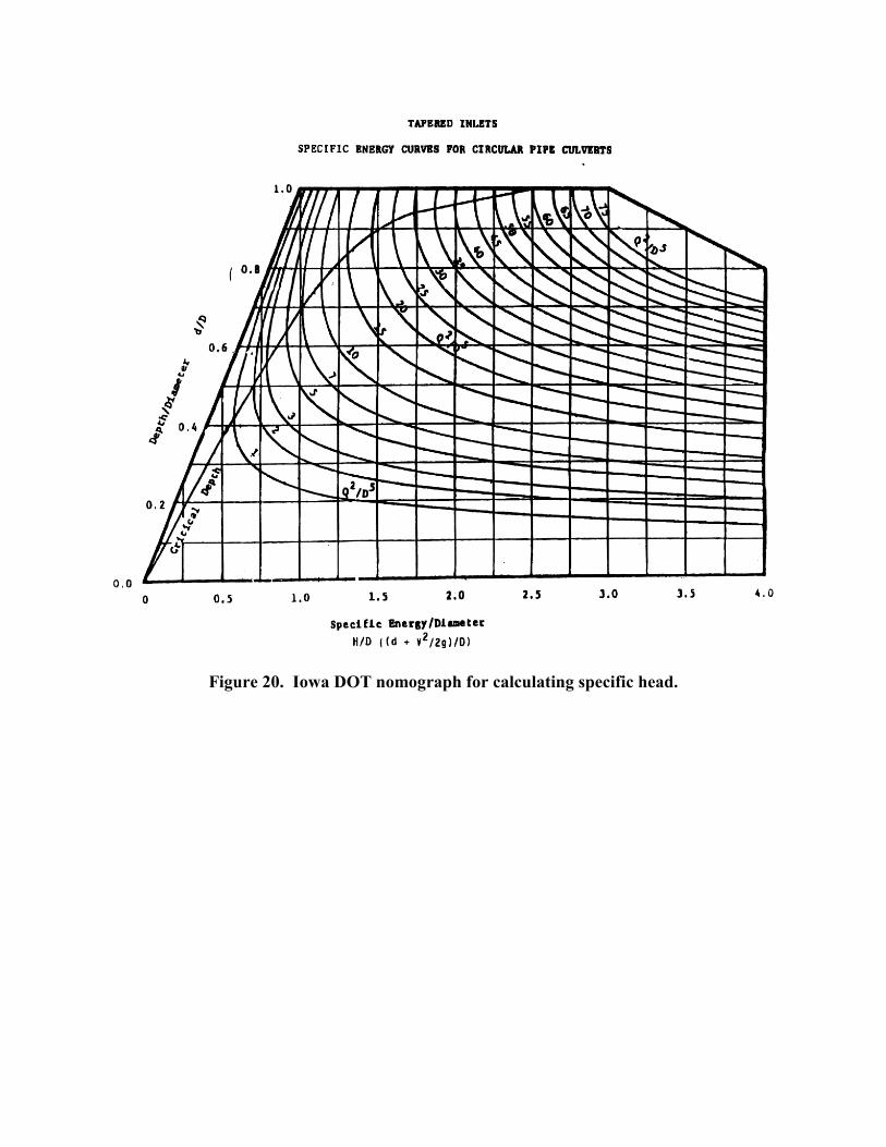
Figure 20. Iowa DOT nomograph for calculating specific head.

Iowa DOT Nomograph Hc versus Calculated Hc
0.60
0.70
0.80
0.90
1.00
0.60 0.65 0.70 0.75 0.80 0.85 0.90 0.95 1.00 1.05
Iowa Nomograph Hc
Cal
cula
ted
Hc
Run 24 Run 8 Run 36
Figure 21. Comparison plot of Iowa DOT nomograph Hc versus calculated Hc..
34

35
APPENDIX A.
CALCULATING SPECIFIC HEAD AT CRITICAL DEPTH
Form 1 of the inlet control equations found in HDS-5 includes the specific head at critical depth, which is defined as:
g
VyH ccc 2
2
+= (1)
Where:
Hc = specific head at critical depth, m yc = critical depth, m Vc = critical velocity, m/s g = gravity, m/s2
Critical velocity is calculated by applying the continuity equation over the cross-sectional area of the barrel. For rectangular cross-sections, the area is simply the depth times the width. However, for pipes flowing partially full, the calculations for cross-sectional area are more complicated. Figure 22 shows the parameters involved with such a calculation. The method for calculating the cross-sectional area in a partially full pipe is accomplished using the following geometric relationships:
( )θθ sin21 2 −= rAF (2)
−=
ry
Arc c1cos2θ (3)
2
sin2 θrT = (4)
TAy F
m = (5)
Where:
AF = partially full flow area, m2 r = pipe radius, m 2 = angle (see figure 22), radians T = top width, m ym = hydraulic mean depth, m

36
yc
T
2
Figure 22. Geometric parameters for pipes flowing partially full.
At critical depth, the Froude number (Fr) is equal to 1:
1==m
cr gy
VF (6)
By substitution:
1=
TAg
AQ
F
F (7)
Rearranging yields:
3/1
3/2
3/1 gQ
TAF = (8)

37
Substituting equations 2 and 4 for AF and T yields:
3/5
3/2
3/1 79.0
2sin
sinrQ=
−θ
θθ (9)
With the above relationships established, a relatively simple procedure can be used to compute Hc for any given flow rate Q:
1. Plug Q and r into equation 9 and solve for 2. This can be accomplished by trial and error or by a direct solution using a computer program or a programmable calculator.
2. Solve for yc using equation 3.
3. Solve for AF using equation 2.
4. Calculate Hc using equation 1 and substituting Q/AF for Vc.

38
APPENDIX B.
LABORATORY DATA

39
Date: 8/11/1997Run#: 1Reducer Number: 4 Inlet No. 12
Barrel Slope: 1.5 percentInlet Diameter: 11.5 inches
Culvert Barrel Diameter: 9.5 inchesBarrel Cross Sectional Area: 0.72131 ft2
Calculated Barrel Diameter: ( 11.5 inches = 0.95833 ft )Barrel Length: 12 feet
Unsubmerged Inlet Control Design Constants
Form (1)K = 1.0000M = 0.0000
Form (2)K = 0.506M = 0.499
Submerged Inlet Control Design Constants
c = 0.0000Y = 0.0000
Definitions: Notes:
HW = Headwater depth above inlet control section invert, ft 1). For mitered inlets use +0.7S instead of -0.5S as the slope correction factorD = Interior height of culvert barrel, ft 2). For Unsubmerged Flow, HW/D<1.2HC = Specific head at critical depth (d + V2/2g), ft 3). For Submerged Flow, HW/D>1.5 Q = Discharge, ft3/s 4). For Unsubmerged Flow, Q/AD0.5 <3.5A = Full cross sectional area of culvert barrel, ft2 5). For Submerged Flow, Q/AD0.5-4.0S = Culvert barrel slope, ft/ft
K,M = ConstantsUnsubmerged Submerged
Form 1 Data Form 2 DataY X Y X Y X
ln(Hw/D-Hc/D+0.5S)Reading Hw Hw D Q Q A S Hc Q/(AD0.5 ) Hw /D Hc /D Hw/D-Hc/D+0.5S ln(Q/(AD0.5 )) ln(Hw /D) ln(Q/(AD0.5 )) Hw/D+0.5S (Q/(AD0.5 ))2
Number (mm) (ft) (ft) (ft3/s) (m3/s) (ft2 ) (ft/ft) (ft)
0 0.0 0.0000 0.9583 0.0000 0.0000 0.72131 0.0150 0.0000 0.0000 0.0000 0.00001 108.6 0.3564 0.9583 0.3637 0.0103 0.72131 0.0150 0.3416 0.5151 0.3719 0.3565 0.0229 -3.7751 -0.6633 -0.9891 -0.66332 154.3 0.5062 0.9583 0.8087 0.0229 0.72131 0.0150 0.5232 1.1453 0.5282 0.5459 -0.0102 #NUM! 0.1356 -0.6382 0.13563 182.2 0.5979 0.9583 1.1724 0.0332 0.72131 0.0150 0.6422 1.6604 0.6239 0.6701 -0.0387 #NUM! 0.5071 -0.4718 0.50714 206.6 0.6779 0.9583 1.3561 0.0384 0.72131 0.0150 0.6971 1.9205 0.7074 0.7274 -0.0125 #NUM! 0.6526 -0.3462 0.65265 229.9 0.7543 0.9583 1.6669 0.0472 0.72131 0.0150 0.7851 2.3606 0.7871 0.8192 -0.0247 #NUM! 0.8589 -0.2395 0.85896 265.9 0.8725 0.9583 2.2072 0.0625 0.72131 0.0150 0.9287 3.1258 0.9104 0.9691 -0.0512 #NUM! 1.1397 -0.0939 1.1397
7 310.2 1.0178 0.9583 2.7334 0.0774 0.72131 0.0150 3.8709 1.0621 1.0696 14.98428 352.8 1.1576 0.9583 3.1995 0.0906 0.72131 0.0150 4.5311 1.2079 1.2154 20.5309
9* 382.6 1.2554 0.9583 3.6975 0.1047 0.72131 0.0150 5.2363 1.3099 1.3174 27.4186
* barrel was full at this point.

40
Form (1)K = 1.0000M = 0.0000
Form (2)K = 0.479M = 0.549
Submerged Inlet Control Design Constants
c = 0.020Y = 0.772
Definitions: Notes:
HW = Headwater depth above inlet control section invert, ft 1). For mitered inlets use +0.7S instead of -0.5S as the slope correction factorD = Interior height of culvert barrel, ft 2). For Unsubmerged Flow, HW/D<1.2HC = Specific head at critical depth (d + V2/2g), ft 3). For Submerged Flow, HW/D>1.5 Q = Discharge, ft3/s 4). For Unsubmerged Flow, Q/AD0.5 <3.5A = Full cross sectional area of culvert barrel, ft2 5). For Submerged Flow, Q/AD0.5-4.0S = Culvert barrel slope, ft/ft
K,M = ConstantsUnsubmerged Submerged
Form 1 Data Form 2 DataY X Y X Y X
ln(Hw/D-Hc/D+0.5S)Reading Hw Hw D Q Q A S Hc Q/(AD0.5 ) Hw /D Hc /D Hw/D-Hc/D+0.5S ln(Q/(AD0.5 )) ln(Hw /D) ln(Q/(AD0.5 )) Hw/D+0.5S (Q/(AD0.5 ))2
Number (mm) (ft) (ft) (ft3/s) (m3/s) (ft2 ) (ft/ft) (ft)
0 0.0 0.0000 0.9583 0.0000 0.0000 0.72131 0.0100 0.0000 0.0000 0.0000 0.00001 108.0 0.3543 0.9583 0.4202 0.0119 0.72131 0.0100 0.3686 0.5951 0.3697 0.3846 -0.0099 #NUM! -0.5190 -0.9950 -0.51902 149.2 0.4895 0.9583 0.8087 0.0229 0.72131 0.0100 0.5232 1.1453 0.5108 0.5459 -0.0302 #NUM! 0.1356 -0.6718 0.13563 178.3 0.5851 0.9583 1.2148 0.0344 0.72131 0.0100 0.6551 1.7204 0.6105 0.6836 -0.0680 #NUM! 0.5426 -0.4934 0.54264 204.9 0.6724 0.9583 1.4197 0.0402 0.72131 0.0100 0.7156 2.0105 0.7016 0.7467 -0.0401 #NUM! 0.6984 -0.3544 0.69845 225.6 0.7402 0.9583 1.6880 0.0478 0.72131 0.0100 0.7909 2.3906 0.7723 0.8253 -0.0479 #NUM! 0.8715 -0.2583 0.87156 250.5 0.8219 0.9583 2.0306 0.0575 0.72131 0.0100 0.8827 2.8757 0.8576 0.9211 -0.0585 #NUM! 1.0563 -0.1536 1.05637 265.2 0.8702 0.9583 2.2213 0.0629 0.72131 0.0100 0.9324 3.1458 0.9080 0.9729 -0.0599 #NUM! 1.1461 -0.0965 1.14618 284.6 0.9338 0.9583 2.4791 0.0702 0.72131 0.0100 0.9986 3.5108 0.9744 1.0420 -0.0625 #NUM! 1.2559 -0.0259 1.2559
9 313.2 1.0276 0.9583 2.8287 0.0801 0.72131 0.0100 4.0060 1.0722 1.0772 16.047710 344.0 1.1286 0.9583 3.1465 0.0891 0.72131 0.0100 4.4561 1.1777 1.1827 19.856611 368.2 1.2079 0.9583 3.4397 0.0974 0.72131 0.0100 4.8712 1.2604 1.2654 23.728312 383.0 1.2566 0.9583 3.6975 0.1047 0.72131 0.0100 5.2363 1.3112 1.3162 27.418413 402.4 1.3201 0.9583 3.9235 0.1111 0.72131 0.0100 5.5563 1.3775 1.3825 30.8729
14* 448.1 1.4701 0.9583 4.1459 0.1174 0.72131 0.0100 5.8714 1.5341 1.5391 34.4735
* barrel was full at this point

41
Date: 7/31/1997Run#: 3Reducer Number: 5 Inlet No. 12
Barrel Slope: 1.5 percentInlet Diameter: 11.5 inches
Culvert Barrel Diameter: 9.5 inchesBarrel Cross Sectional Area: 0.72131 ft2
Calculated Barrel Diameter: ( 11.5 inches = 0.95833 ft )Barrel Length: 12 feet
Unsubmerged Inlet Control Design Constants
Form (1)K = 1.0000M = 0.0000
Form (2)K = 0.487M = 0.524
Submerged Inlet Control Design Constants
c = 0.0000Y = 0.0000
Definitions: Notes:
HW = Headwater depth above inlet control sction invert, ft 1). For mitered inlets use +0.7S instead of -0.5S as the slope correction factorD = Interior height of culvert barrel, ft 2). For Unsubmerged Flow, HW/D<1.2HC = Specific head at critical depth (d + V2/2g), ft 3). For Submerged Flow, HW/D>1.5 Q = Discharge, ft3/s 4). For Unsubmerged Flow, Q/AD0.5 <3.5A = Full cross sectional area of culvert barrel, ft2 5). For Submerged Flow, Q/AD0.5-4.0S = Culvert barrel slope, ft/ft
K,M = ConstantsUnsubmerged
Form 1 Data Form 2 Data Y XY X Y X
ln(Hw/D-Hc/D+0.5S) Hw/D+0.5S (Q/(AD0.5 ))2
Reading Hw Hw D Q Q A S Hc Q/(AD0.5 ) Hw /D Hc /D Hw/D-Hc/D+0.5S ln(Q/(AD0.5 )) ln(Hw /D) ln(Q/(AD0.5 ))Number (mm) (ft) (ft) (ft3/s) (m3/s) (ft2 ) (ft/ft) (ft)
0 0.0 0.0000 0.9583 0.0000 0.0000 0.72131 0.0150 0.0000 0.0000 0.0000 0.00001 98.2 0.3221 0.9583 0.3284 0.0093 0.72131 0.0150 0.3238 0.4651 0.3361 0.3379 0.0057 -5.1696 -0.7655 -1.0904 -0.76552 145.5 0.4773 0.9583 0.7487 0.0212 0.72131 0.0150 0.5017 1.0603 0.4980 0.5236 -0.0180 #NUM! 0.0585 -0.6971 0.05853 176.3 0.5785 0.9583 1.1972 0.0339 0.72131 0.0150 0.6497 1.6954 0.6037 0.6780 -0.0668 #NUM! 0.5279 -0.5047 0.52794 201.4 0.6608 0.9583 1.4055 0.0398 0.72131 0.0150 0.7115 1.9905 0.6895 0.7424 -0.0454 #NUM! 0.6884 -0.3718 0.68845 225.8 0.7408 0.9583 1.6951 0.0480 0.72131 0.0150 0.7928 2.4006 0.7730 0.8273 -0.0468 #NUM! 0.8757 -0.2574 0.87576 249.4 0.8182 0.9583 2.0235 0.0573 0.72131 0.0150 0.8808 2.8657 0.8538 0.9191 -0.0578 #NUM! 1.0528 -0.1580 1.05287 266.2 0.8735 0.9583 2.2566 0.0639 0.72131 0.0150 0.9415 3.1958 0.9114 0.9824 -0.0635 #NUM! 1.1618 -0.0927 1.16188 281.9 0.9250 0.9583 2.4791 0.0702 0.72131 0.0150 0.9986 3.5108 0.9652 1.0420 -0.0693 #NUM! 1.2559 -0.0354 1.2559
1.0780 16.16829 312.7 1.0259 0.9583 2.8393 0.0804 0.72131 0.0150 4.0210 1.0705 1.1638 19.8120
10 337.8 1.1082 0.9583 3.1430 0.0890 0.72131 0.0150 4.4511 1.15631.28389 27.52326
11* 372.8 1.2232 0.9583 3.7045 0.1049 0.72131 0.0150 5.24626 1.27639 1.36856 31.8813612* 397.6 1.3044 0.9583 3.9870 0.1129 0.72131 0.0150 5.64636 1.36106
* barrel was full at this point

42
Date: 8/5/1997Run#: 4Reducer Number: 5 Inlet No. 12
Barrel Slope: 2.0 percentInlet Diameter: 11.5 inches
Culvert Barrel Diameter: 9.5 inchesBarrel Cross Sectional Area: 0.72131 ft2
Calculated Barrel Diameter: ( 11.5 inches = 0.95833 ft )Barrel Length: 12 feet
Unsubmerged Inlet Control Design Constants
Form (1)K = 1.0000M = 0.0000
Form (2)K = 0.458M = 0.557
Submerged Inlet Control Design Constants
c = 0.031Y = 0.566
Definitions: Notes:
HW = Headwater depth above inlet control section invert, ft 1). For mitered inlets use +0.7S instead of -0.5S as the slope correction factorD = Interior height of culvert barrel, ft 2). For Unsubmerged Flow, HW/D<1.2HC = Specific head at critical depth (d + V2/2g), ft 3). For Submerged Flow, HW/D>1.5 Q = Discharge, ft3/s 4). For Unsubmerged Flow, Q/AD0.5 <3.5A = Full cross sectional area of culvert barrel, ft2 5). For Submerged Flow, Q/AD0.5-4.0S = Culvert barrel slope, ft/ft
K,M = Constants
Unsubmerged Submerged Form 1 Data Form 2 Data
Y X Y X Y Xln(Hw/D-Hc/D+0.5S)
Reading Hw Hw D Q Q A S Hc Q/(AD0.5 ) Hw /D Hc /D Hw/D-Hc/D+0.5S ln(Q/(AD0.5 )) ln(Hw /D) ln(Q/(AD0.5 )) Hw/D+0.5S (Q/(AD0.5 ))2
Number (mm) (ft) (ft) (ft3/s) (m3/s) (ft2 ) (ft/ft) (ft)
0 0.0 0.0000 0.9583 0.0000 0.0000 0.72131 0.0200 0.0000 0.00000 0.00000 0.00001 58.7 0.1926 0.9583 0.1554 0.0044 0.72131 0.0200 0.2196 0.2201 0.2010 0.2292 -0.0182 #NUM! -1.5139 -1.6047 -1.51392 95.4 0.3129 0.9583 0.3849 0.0109 0.72131 0.0200 0.3519 0.5451 0.3265 0.3672 -0.0308 #NUM! -0.6067 -1.1194 -0.60673 138.3 0.4538 0.9583 0.7734 0.0219 0.72131 0.0200 0.5107 1.0953 0.4736 0.5329 -0.0493 #NUM! 0.0910 -0.7474 0.09104 168.0 0.5512 0.9583 1.1901 0.0337 0.72131 0.0200 0.6476 1.6854 0.5751 0.6757 -0.0906 #NUM! 0.5220 -0.5531 0.52205 197.3 0.6473 0.9583 1.3914 0.0394 0.72131 0.0200 0.7074 1.9705 0.6755 0.7381 -0.0527 #NUM! 0.6783 -0.3924 0.67836 214.7 0.7045 0.9583 1.6492 0.0467 0.72131 0.0200 0.7802 2.3356 0.7351 0.8141 -0.0690 #NUM! 0.8483 -0.3077 0.84837 234.9 0.7707 0.9583 1.9211 0.0544 0.72131 0.0200 0.8602 2.7207 0.8042 0.8976 -0.0835 #NUM! 1.0009 -0.2179 1.00098 257.4 0.8445 0.9583 2.2284 0.0631 0.72131 0.0200 0.9378 3.1558 0.8812 0.9786 -0.0874 #NUM! 1.1492 -0.1265 1.14929 276.0 0.9056 0.9583 2.4826 0.0703 0.72131 0.0200 0.9995 3.5158 0.9450 1.0429 -0.0879 #NUM! 1.2573 -0.0566 1.2573
10 305.9 1.0036 0.9583 2.8393 0.0804 0.72131 0.0200 4.0210 1.0472 1.0572 16.168211 323.6 1.0617 0.9583 2.9735 0.0842 0.72131 0.0200 4.2110 1.1078 1.1178 17.732612 338.9 1.1118 0.9583 3.1430 0.0890 0.72131 0.0200 4.4511 1.1601 1.1701 19.8120
13* 367.6 1.2060 0.9583 3.7116 0.1051 0.72131 0.0200 5.2563 1.2585 1.2685 27.628314* 377.4 1.2383 0.9583 3.9305 0.1113 0.72131 0.0200 5.5663 1.2921 1.3021 30.984115* 398.5 1.3075 0.9583 4.1565 0.1177 0.72131 0.0200 5.8864 1.3644 1.3744 34.6499
* barrel was full at this point

43
Date: 8/11/1997Run#: 5Reducer Number: 6 Inlet No. 12
Barrel Slope: 1.5 percentInlet Diameter: 11.5 inches
Culvert Barrel Diameter: 9.5 inchesBarrel Cross Sectional Area: 0.72131 ft2
Calculated Barrel Diameter: ( 11.5 inches = 0.95833 ft )Barrel Length: 12 feet
Unsubmerged Inlet Control Design Constants
Form (1)K = 1.0000M = 0.0000
Form (2)K = 0.477M = 0.539
Submerged Inlet Control Design Constants
c = 0.050Y = 0.246
Definitions: Notes:
HW = Headwater depth above inlet control section invert, ft 1). For mitered inlets use +0.7S instead of -0.5S as the slope correction factorD = Interior height of culvert barrel, ft 2). For Unsubmerged Flow, HW/D<1.2HC = Specific head at critical depth (d + V2/2g), ft 3). For Submerged Flow, HW/D>1.5 Q = Discharge, ft3/s 4). For Unsubmerged Flow, Q/AD0.5 <3.5A = Full cross sectional area of culvert barrel, ft2 5). For Submerged Flow, Q/AD0.5-4.0S = Culvert barrel slope, ft/ft
K,M = ConstantsUnsubmerged Submerged
Form 1 Data Form 2 DataY X Y X Y X
ln(Hw/D-Hc/D+0.5S)Reading Hw Hw D Q Q A S Hc Q/(AD0.5 ) Hw /D Hc /D Hw/D-Hc/D+0.5S ln(Q/(AD0.5 )) ln(Hw /D) ln(Q/(AD0.5 )) Hw/D+0.5S (Q/(AD0.5 ))2
Number (mm) (ft) (ft) (ft3/s) (m3/s) (ft2 ) (ft/ft) (ft)
0 0.0 0.0000 0.9583 0.0000 0.0000 0.72131 0.0150 0.0000 0.0000 0.0000 0.00001 63.6 0.2088 0.9583 0.1589 0.0045 0.72131 0.0150 0.2222 0.2251 0.2178 0.2318 -0.0065 #NUM! -1.4914 -1.5240 -1.49142 104.0 0.3411 0.9583 0.4167 0.0118 0.72131 0.0150 0.3670 0.5901 0.3559 0.3829 -0.0195 #NUM! -0.5274 -1.0330 -0.52743 149.5 0.4906 0.9583 0.8476 0.0240 0.72131 0.0150 0.5367 1.2003 0.5119 0.5601 -0.0407 #NUM! 0.1826 -0.6696 0.18264 180.1 0.5910 0.9583 1.1407 0.0323 0.72131 0.0150 0.6324 1.6154 0.6167 0.6599 -0.0357 #NUM! 0.4796 -0.4834 0.47965 200.4 0.6575 0.9583 1.3949 0.0395 0.72131 0.0150 0.7084 1.9755 0.6861 0.7392 -0.0456 #NUM! 0.6808 -0.3768 0.68086 224.4 0.7361 0.9583 1.7022 0.0482 0.72131 0.0150 0.7948 2.4106 0.7681 0.8293 -0.0537 #NUM! 0.8799 -0.2638 0.87997 246.9 0.8101 0.9583 2.0483 0.0580 0.72131 0.0150 0.8873 2.9007 0.8454 0.9259 -0.0730 #NUM! 1.0650 -0.1680 1.06508 266.6 0.8746 0.9583 2.3096 0.0654 0.72131 0.0150 0.9551 3.2708 0.9126 0.9967 -0.0766 #NUM! 1.1850 -0.0915 1.18509 280.1 0.9191 0.9583 2.4968 0.0707 0.72131 0.0150 1.0031 3.5359 0.9590 1.0467 -0.0802 #NUM! 1.2630 -0.0418 1.2630
10 310.2 1.0177 0.9583 2.8358 0.0803 0.72131 0.0150 4.0160 1.0620 1.0695 16.128011 325.2 1.0669 0.9583 2.9735 0.0842 0.72131 0.0150 4.2110 1.1133 1.1208 17.732612 363.9 1.1938 0.9583 3.1571 0.0894 0.72131 0.0150 4.4711 1.2457 1.2532 19.990513 423.3 1.3887 0.9583 3.4608 0.0980 0.72131 0.0150 4.9012 1.4490 1.4565 24.0216
14* 390.2 1.2802 0.9583 3.7434 0.106 0.72131 0.0150 5.3013 1.3358 1.3433 28.103515* 410.0 1.3450 0.9583 3.9341 0.1114 0.72131 0.0150 5.5713 1.4035 1.4110 31.039816* 468.7 1.5377 0.9583 4.2307 0.1198 0.72131 0.0150 5.9914 1.6046 1.6121 35.8974
* barrel was full at this point

44
Date: 9/2/1997Run#: 6Reducer Number: 7 Inlet No. 12
Barrel Slope: 2.0 percentInlet Diameter: 11.5 inches/8.75 inches
Culvert Barrel Diameter: 8.75 inchesBarrel Cross Sectional Area: 0.41758 ft2
Calculated Barrel Diameter: ( 8.75 inches = 0.729166 ft )Barrel Length: 12 feet
Unsubmerged Inlet Control Design Constants
Form (1)K = 1.0000M = 0.0000
Form (2)K = 0.480M = 0.527
Submerged Inlet Control Design Constants
c = 0.0000Y = 0.0000
Definitions: Notes:
HW = Headwater depth above inlet control section invert, ft 1). For mitered inlets use +0.7S instead of -0.5S as the slope correction factorD = Interior height of culvert barrel, ft 2). For Unsubmerged Flow, HW/D<1.2HC = Specific head at critical depth (d + V2/2g), ft 3). For Submerged Flow, HW/D>1.5 Q = Discharge, ft3/s 4). For Unsubmerged Flow, Q/AD0.5 <3.5A = Full cross sectional area of culvert barrel, ft2 5). For Submerged Flow, Q/AD0.5-4.0S = Culvert barrel slope, ft/ft
K,M = ConstantsUnsubmerged Submerged
Form 1 Data Form 2 DataY X Y X Y X
ln(Hw/D-Hc/D+0.5S)Reading Hw Hw D Q Q A S Hc Q/(AD0.5 ) Hw /D Hc /D Hw/D-Hc/D+0.5S ln(Q/(AD0.5 )) ln(Hw /D) ln(Q/(AD0.5 )) Hw/D+0.5S (Q/(AD0.5 ))2
Number (mm) (ft) (ft) (ft3/s) (m3/s) (ft2 ) (ft/ft) (ft)
0 0.0 0.0000 0.9583 0.0000 0.0000 0.72131 0.0200 0.0000 0.0000 0.0000 0.00001 64.8 0.2127 0.9583 0.1554 0.0044 0.72131 0.0200 0.2196 0.2201 0.2220 0.2292 0.0028 -5.8836 -1.5139 -1.5053 -1.51392 84.9 0.2787 0.9583 0.2719 0.0077 0.72131 0.0200 0.2934 0.3851 0.2908 0.3062 -0.0054 #NUM! -0.9543 -1.2352 -0.95433 123.1 0.4038 0.9583 0.5827 0.0165 0.72131 0.0200 0.4384 0.8252 0.4213 0.4575 -0.0262 #NUM! -0.1921 -0.8644 -0.19214 169.4 0.5557 0.9583 1.2537 0.0355 0.72131 0.0200 0.6668 1.7754 0.5798 0.6958 -0.1060 #NUM! 0.5740 -0.5450 0.57405 198.6 0.6515 0.9583 1.3631 0.0386 0.72131 0.0200 0.6992 1.9305 0.6798 0.7296 -0.0398 #NUM! 0.6578 -0.3860 0.65786 220.8 0.7245 0.9583 1.5538 0.0440 0.72131 0.0200 0.7537 2.2005 0.7560 0.7865 -0.0205 #NUM! 0.7887 -0.2797 0.78877 242.8 0.7967 0.9583 1.8858 0.0534 0.72131 0.0200 0.8444 2.6706 0.8313 0.8811 -0.0397 #NUM! 0.9823 -0.1847 0.98238 260.1 0.8533 0.9583 2.1295 0.0603 0.72131 0.0200 0.9085 3.0157 0.8904 0.9480 -0.0476 #NUM! 1.1038 -0.1160 1.1038
9* 302.7 0.9930 0.9583 2.6274 0.0744 0.72131 0.0200 3.7209 1.0362 1.0462 13.845110* 362.7 1.1900 0.9583 3.1254 0.0885 0.72131 0.0200 4.4261 1.2417 1.2517 19.590211* 450.6 1.4785 0.9583 3.6339 0.1029 0.72131 0.0200 5.1463 1.5427 1.5527 26.4839
"*" means that the barrel was full at this point.

45
Date: 8/27/1997Run#: 7Reducer Number: 8 Inlet No. 12
Barrel Slope: 2.0 percentInlet Diameter: 11.5 inches/8.75 inches
Culvert Barrel Diameter: 8.75 inchesBarrel Cross Sectional Area: 0.41758 ft2
Calculated Barrel Diameter: ( 8.75 inches = 0.729166 ft )Barrel Length: 12 feet
Unsubmerged Inlet Control Design Constants
Form (1)K = 1.0000M = 0.0000
Form (2)K = 0.488M = 0.525
Submerged Inlet Control Design Constants
c = 0.0000Y = 0.0000
Definitions: Notes:
HW = Headwater depth above inlet control section invert, ft 1). For mitered inlets use +0.7S instead of -0.5S as the slope correction factorD = Interior height of culvert barrel, ft 2). For Unsubmerged Flow, HW/D<1.2HC = Specific head at critical depth (d + V2/2g), ft 3). For Submerged Flow, HW/D>1.5 Q = Discharge, ft3/s 4). For Unsubmerged Flow, Q/AD0.5 <3.5A = Full cross sectional area of culvert barrel, ft2 5). For Submerged Flow, Q/AD0.5-4.0S = Culvert barrel slope, ft/ft
K,M = ConstantsUnsubmerged Submerged
Form 1 Data Form 2 DataY X Y X Y X
ln(Hw/D-Hc/D+0.5S)Reading Hw Hw D Q Q A S Hc Q/(AD0.5 ) Hw /D Hc /D Hw/D-Hc/D+0.5S ln(Q/(AD0.5 )) ln(Hw /D) ln(Q/(AD0.5 )) Hw/D+0.5S (Q/(AD0.5 ))2
Number (mm) (ft) (ft) (ft3/s) (m3/s) (ft2 ) (ft/ft) (ft)
0 0.0 0.0000 0.9583 0.0000 0.0000 0.72131 0.0200 0.0000 0.0000 0.0000 0.00001 80.4 0.2637 0.9583 0.2260 0.0064 0.72131 0.0200 0.2665 0.3201 0.2751 0.2781 0.0070 -4.9592 -1.1392 -1.2905 -1.13922 112.6 0.3694 0.9583 0.4591 0.0130 0.72131 0.0200 0.3862 0.6502 0.3855 0.4030 -0.0075 #NUM! -0.4305 -0.9533 -0.43053 151.7 0.4978 0.9583 0.8122 0.0230 0.72131 0.0200 0.5244 1.1503 0.5195 0.5472 -0.0178 #NUM! 0.1400 -0.6550 0.14004 179.3 0.5884 0.9583 1.2148 0.0344 0.72131 0.0200 0.6551 1.7204 0.6139 0.6836 -0.0596 #NUM! 0.5426 -0.4878 0.54265 205.5 0.6742 0.9583 1.4197 0.0402 0.72131 0.0200 0.7156 2.0105 0.7035 0.7467 -0.0331 #NUM! 0.6984 -0.3516 0.69846 227.8 0.7473 0.9583 1.6598 0.0470 0.72131 0.0200 0.7831 2.3506 0.7798 0.8172 -0.0274 #NUM! 0.8547 -0.2488 0.85477 245.7 0.8061 0.9583 1.9247 0.0545 0.72131 0.0200 0.8547 2.7257 0.8412 0.8919 -0.0407 #NUM! 1.0027 -0.1730 1.00278 265.8 0.8720 0.9583 2.2142 0.0627 0.72131 0.0200 0.9305 3.1358 0.9100 0.9710 -0.0510 #NUM! 1.1429 -0.0944 1.1429
9* 462.8 1.5184 0.9583 3.7080 0.1050 0.72131 0.0200 5.2513 1.5844 0.0000 1.5944 0.4665 1.6585 1.5944 27.575910* 539.9 1.7712 0.9583 3.9694 0.1124 0.72131 0.0200 5.6214 1.8482 0.0000 1.8582 0.6196 1.7266 1.8582 31.5998
* barrel was full at this point

46
Date: 9/4/1997Run#: 8Reducer Number: 9 Inlet No. 12
Barrel Slope: 2.0 percentInlet Diameter: 11.5 inches/8.75 inches
Culvert Barrel Diameter: 8.75 inchesBarrel Cross Sectional Area: 0.41758 ft2
Calculated Barrel Diameter: ( 8.75 inches = 0.729166 ft )Barrel Length: 12 feet
Unsubmerged Inlet Control Design Constants
Form (1)K = 1.0000M = 0.0000
Form (2)K = 0.461M = 0.556
Submerged Inlet Control Design Constants
c = 0.0000Y = 0.0000
Definitions: Notes:
HW = Headwater depth above inlet control section invert, ft 1). For mitered inlets use +0.7S instead of -0.5S as the slope correction factorD = Interior height of culvert barrel, ft 2). For Unsubmerged Flow, HW/D<1.2HC = Specific head at critical depth (d + V2/2g), ft 3). For Submerged Flow, HW/D>1.5 Q = Discharge, ft3/s 4). For Unsubmerged Flow, Q/AD0.5 <3.5A = Full cross sectional area of culvert barrel, ft2 5). For Submerged Flow, Q/AD0.5-4.0S = Culvert barrel slope, ft/ft
K,M = ConstantsUnsubmerged Submerged
Form 1 Data Form 2 DataY X Y X Y X
ln(Hw/D-Hc/D+0.5S)Reading Hw Hw D Q Q A S Hc Q/(AD0.5 ) Hw /D Hc /D Hw/D-Hc/D+0.5S ln(Q/(AD0.5 )) ln(Hw /D) ln(Q/(AD0.5 )) Hw/D+0.5S (Q/(AD0.5 ))2
Number (mm) (ft) (ft) (ft3/s) (m3/s) (ft2 ) (ft/ft) (ft)
0 0.0 0.0000 0.9583 0.0000 0.0000 0.72131 0.0200 0.0000 0.0000 0.0000 0.00001 51.1 0.1677 0.9583 0.1201 0.0034 0.72131 0.0200 0.1924 0.1700 0.1749 0.2007 -0.0158 #NUM! -1.7717 -1.7433 -1.77172 81.6 0.2676 0.9583 0.2860 0.0081 0.72131 0.0200 0.3013 0.4051 0.2792 0.3144 -0.0251 #NUM! -0.9036 -1.2757 -0.90363 127.8 0.4193 0.9583 0.6498 0.0184 0.72131 0.0200 0.4648 0.9202 0.4375 0.4850 -0.0375 #NUM! -0.0831 -0.8266 -0.08314 164.9 0.5410 0.9583 1.2501 0.0354 0.72131 0.0200 0.6657 1.7704 0.5645 0.6947 -0.1201 #NUM! 0.5712 -0.5718 0.57125 193.2 0.6337 0.9583 1.2925 0.0366 0.72131 0.0200 0.6784 1.8304 0.6613 0.7079 -0.0366 #NUM! 0.6046 -0.4135 0.60466 216.5 0.7104 0.9583 1.5750 0.0446 0.72131 0.0200 0.7596 2.2305 0.7413 0.7927 -0.0414 #NUM! 0.8022 -0.2994 0.80227 236.4 0.7757 0.9583 1.8540 0.0525 0.72131 0.0200 0.8359 2.6256 0.8094 0.8722 -0.0528 #NUM! 0.9653 -0.2114 0.96538 255.9 0.8397 0.9583 2.1365 0.0605 0.72131 0.0200 0.9104 3.0257 0.8762 0.9500 -0.0638 #NUM! 1.1072 -0.1322 1.1072
9* 316.2 1.0374 0.9583 2.6521 0.0751 0.72131 0.0200 3.7559 1.0825 1.0925 14.106910* 414.9 1.3611 0.9583 3.1254 0.0885 0.72131 0.0200 4.4261 1.4203 1.4303 19.590211* 438.7 1.4392 0.9583 3.6304 0.1028 0.72131 0.0200 5.1413 1.5018 1.5118 26.4325
* barrel was full at this point

47
Date: 10/31/1997Run#: 9Reducer Number: 1 Inlet No. 13
Barrel Slope: 2.8 percentInlet Diameter: 11.5 inches/8.625 inches
Culvert Barrel Diameter: 8.625 inchesBarrel Cross Sectional Area: 0.4057 ft2
Calculated Barrel Diameter: ( 8.625 inches = 0.71875 ft )Barrel Length: 12 feet
Unsubmerged Inlet Control Design Constants
Form (1)K = 1.0000M = 0.0000
Form (2)K = 0.480M = 0.531
Submerged Inlet Control Design Constants
c = 0.0000Y = 0.0000
Definitions: Notes:
HW = Headwater depth above inlet control section invert, ft 1). For mitered inlets use +0.7S instead of -0.5S as the slope correction factorD = Interior height of culvert barrel, ft 2). For Unsubmerged Flow, HW/D<1.2HC = Specific head at critical depth (d + V2/2g), ft 3). For Submerged Flow, HW/D>1.5 Q = Discharge, ft3/s 4). For Unsubmerged Flow, Q/AD0.5 <3.5A = Full cross sectional area of culvert barrel, ft2 5). For Submerged Flow, Q/AD0.5-4.0S = Culvert barrel slope, ft/ft
K,M = ConstantsUnsubmerged Submerged
Form 1 Data Form 2 DataY X Y X Y X
ln(Hw/D-Hc/D+0.5S)Reading Hw Hw D Q Q A S Hc Q/(AD0.5 ) Hw /D Hc /D Hw/D-Hc/D+0.5S ln(Q/(AD0.5 )) ln(Hw /D) ln(Q/(AD0.5 )) Hw/D+0.5S (Q/(AD0.5 ))2
Number (mm) (ft) (ft) (ft3/s) (m3/s) (ft2 ) (ft/ft) (ft)
0 0.0 0.0000 0.9583 0.0000 0.0000 0.72131 0.0280 0.0000 0.0000 0.0000 0.00001 74.4 0.2441 0.9583 0.1978 0.0056 0.72131 0.0280 0.2487 0.2801 0.2547 0.2595 0.0092 -4.6916 -1.2727 -1.3676 -1.27272 108.4 0.3556 0.9583 0.4662 0.0132 0.72131 0.0280 0.3894 0.6602 0.3711 0.4063 -0.0212 #NUM! -0.4153 -0.9913 -0.41533 146.7 0.4814 0.9583 0.8193 0.0232 0.72131 0.0280 0.5269 1.1603 0.5023 0.5498 -0.0335 #NUM! 0.1487 -0.6885 0.14874 175.6 0.5760 0.9583 1.1018 0.0312 0.72131 0.0280 0.6203 1.5604 0.6011 0.6472 -0.0322 #NUM! 0.4449 -0.5091 0.44495 200.3 0.6572 0.9583 1.3985 0.0396 0.72131 0.0280 0.7094 1.9805 0.6857 0.7403 -0.0406 #NUM! 0.6833 -0.3773 0.68336 221.4 0.7264 0.9583 1.6669 0.0472 0.72131 0.0280 0.7851 2.3606 0.7580 0.8192 -0.0473 #NUM! 0.8589 -0.2771 0.85897 243.5 0.7988 0.9583 1.9529 0.0553 0.72131 0.0280 0.8622 2.7657 0.8335 0.8997 -0.0522 #NUM! 1.0173 -0.1821 1.01738 263.7 0.8650 0.9583 2.2390 0.0634 0.72131 0.0280 0.9369 3.1708 0.9027 0.9777 -0.0610 #NUM! 1.1540 -0.1024 1.15409 278.3 0.9131 0.9583 2.4932 0.0706 0.72131 0.0280 1.0022 3.5309 0.9528 1.0457 -0.0790 #NUM! 1.2615 -0.0484 1.2615
10* 379.1 1.2437 0.9583 3.4891 0.0988 0.72131 0.0280 4.9412 1.2977 1.3117 24.415511* 533.0 1.7486 0.9583 4.0506 0.1147 0.72131 0.0280 5.7364 1.8246 1.8386 32.9062
* barrel was full at this point

48
Date: 10/16/1997Run#: 10Reducer Number: 2 Inlet No. 13
Barrel Slope: 1.0 percentInlet Diameter: 11.5 inches/8.625 inches
Culvert Barrel Diameter: 8.625 inchesBarrel Cross Sectional Area: 0.4057 ft2
Calculated Barrel Diameter: ( 8.625 inches = 0.71875 ft )Barrel Length: 12 feet
Unsubmerged Inlet Control Design Constants
Form (1)K = 1.0000M = 0.0000
Form (2)K = 0.460M = 0.531
Submerged Inlet Control Design Constants
c = 0.0000Y = 0.0000
Definitions: Notes:
HW = Headwater depth above inlet control section invert, ft 1). For mitered inlets use +0.7S instead of -0.5S as the slope correction factorD = Interior height of culvert barrel, ft 2). For Unsubmerged Flow, HW/D<1.2HC = Specific head at critical depth (d + V2/2g), ft 3). For Submerged Flow, HW/D>1.5 Q = Discharge, ft3/s 4). For Unsubmerged Flow, Q/AD0.5 <3.5A = Full cross sectional area of culvert barrel, ft2 5). For Submerged Flow, Q/AD0.5-4.0S = Culvert barrel slope, ft/ft
K,M = ConstantsUnsubmerged Submerged
Form 1 Data Form 2 DataY X Y X Y X
ln(Hw/D-Hc/D+0.5S)Reading Hw Hw D Q Q A S Hc Q/(AD0.5 ) Hw /D Hc /D Hw/D-Hc/D+0.5S ln(Q/(AD0.5 )) ln(Hw /D) ln(Q/(AD0.5 )) Hw/D+0.5S (Q/(AD0.5 ))2
Number (mm) (ft) (ft) (ft3/s) (m3/s) (ft2 ) (ft/ft) (ft)
0 0.0 0.0000 0.9583 0.0000 0.0000 0.72131 0.0100 0.0000 0.0000 0.0000 0.00001 65.6 0.2152 0.9583 0.1695 0.0048 0.72131 0.0100 0.2297 0.2401 0.2246 0.2397 -0.0101 #NUM! -1.4269 -1.4935 -1.42692 105.5 0.3460 0.9583 0.4803 0.0136 0.72131 0.0100 0.3956 0.6802 0.3611 0.4128 -0.0467 #NUM! -0.3854 -1.0187 -0.38543 143.2 0.4697 0.9583 0.8264 0.0234 0.72131 0.0100 0.5294 1.1703 0.4901 0.5524 -0.0573 #NUM! 0.1572 -0.7131 0.15724 169.5 0.5561 0.9583 1.2113 0.0343 0.72131 0.0100 0.6540 1.7154 0.5803 0.6824 -0.0972 #NUM! 0.5397 -0.5442 0.53975 193.4 0.6344 0.9583 1.4161 0.0401 0.72131 0.0100 0.7145 2.0055 0.6620 0.7456 -0.0786 #NUM! 0.6959 -0.4125 0.69596 216.4 0.7099 0.9583 1.6421 0.0465 0.72131 0.0100 0.7783 2.3256 0.7407 0.8121 -0.0664 #NUM! 0.8440 -0.3001 0.84407 236.2 0.7749 0.9583 1.9247 0.0545 0.72131 0.0100 0.8547 2.7257 0.8086 0.8919 -0.0782 #NUM! 1.0027 -0.2124 1.00278 253.1 0.8305 0.9583 2.2178 0.0628 0.72131 0.0100 0.9315 3.1408 0.8666 0.9720 -0.1004 #NUM! 1.1445 -0.1432 1.1445
9* 367.8 1.2066 0.9583 3.1960 0.0905 0.72131 0.0100 4.5261 1.2590 1.2640 20.485610* 429.1 1.4079 0.9583 3.4538 0.0978 0.72131 0.0100 4.8912 1.4691 1.4741 23.923711* 489.4 1.6055 0.9583 3.6798 0.1042 0.72131 0.0100 5.2113 1.6753 1.6803 27.157312* 553.8 1.8168 0.9583 3.9093 0.1107 0.72131 0.0100 5.5363 1.8958 1.9008 30.651113* 619.3 2.0318 0.9583 4.1248 0.1168 0.72131 0.0100 5.8414 2.1202 2.1252 34.1222
* barrel was full at this point

49
Date: 10/17/1997Run#: 11Reducer Number: 2 Inlet No. 13
Barrel Slope: 2.0 percentInlet Diameter: 11.5 inches/8.625 inches
Culvert Barrel Diameter: 8.625 inchesBarrel Cross Sectional Area: 0.4057 ft2
Calculated Barrel Diameter: ( 8.625 inches = 0.71875 ft )Barrel Length: 12 feet
Unsubmerged Inlet Control Design Constants
Form (1)K = 1.0000M = 0.0000
Form (2)K = 0.475M = 0.505
Submerged Inlet Control Design Constants
c = 0.0000Y = 0.0000
Definitions: Notes:
HW = Headwater depth above inlet control section invert, ft 1). For mitered inlets use +0.7S instead of -0.5S as the slope correction factorD = Interior height of culvert barrel, ft 2). For Unsubmerged Flow, HW/D<1.2HC = Specific head at critical depth (d + V2/2g), ft 3). For Submerged Flow, HW/D>1.5 Q = Discharge, ft3/s 4). For Unsubmerged Flow, Q/AD0.5 <3.5A = Full cross sectional area of culvert barrel, ft2 5). For Submerged Flow, Q/AD0.5-4.0S = Culvert barrel slope, ft/ft
K,M = ConstantsUnsubmerged Submerged
Form 1 Data Form 2 DataY X Y X Y X
ln(Hw/D-Hc/D+0.5S)Reading Hw Hw D Q Q A S Hc Q/(AD0.5 ) Hw /D Hc /D Hw/D-Hc/D+0.5S ln(Q/(AD0.5 )) ln(Hw /D) ln(Q/(AD0.5 )) Hw/D+0.5S (Q/(AD0.5 ))2
Number (mm) (ft) (ft) (ft3/s) (m3/s) (ft2 ) (ft/ft) (ft)
0 0.0 0.0000 0.9583 0.0000 0.0000 0.72131 0.0200 0.0000 0.0000 0.0000 0.00001 65.6 0.2152 0.9583 0.1519 0.0043 0.72131 0.0200 0.2170 0.2151 0.2246 0.2265 0.0081 -4.8152 -1.5369 -1.4935 -1.53692 105.5 0.3460 0.9583 0.4273 0.0121 0.72131 0.0200 0.3718 0.6051 0.3611 0.3880 -0.0170 #NUM! -0.5023 -1.0187 -0.50233 143.2 0.4697 0.9583 0.7593 0.0215 0.72131 0.0200 0.5056 1.0753 0.4901 0.5276 -0.0274 #NUM! 0.0726 -0.7131 0.07264 169.5 0.5561 0.9583 1.1866 0.0336 0.72131 0.0200 0.6465 1.6804 0.5803 0.6746 -0.0843 #NUM! 0.5190 -0.5442 0.51905 193.4 0.6344 0.9583 1.4091 0.0399 0.72131 0.0200 0.7125 1.9955 0.6620 0.7435 -0.0715 #NUM! 0.6909 -0.4125 0.69096 216.4 0.7099 0.9583 1.6315 0.0462 0.72131 0.0200 0.7753 2.3106 0.7407 0.8090 -0.0583 #NUM! 0.8375 -0.3001 0.83757 236.2 0.7749 0.9583 1.9141 0.0542 0.72131 0.0200 0.8519 2.7107 0.8086 0.8889 -0.0703 #NUM! 0.9972 -0.2124 0.99728 253.1 0.8305 0.9583 2.1966 0.0622 0.72131 0.0200 0.9260 3.1108 0.8666 0.9662 -0.0896 #NUM! 1.1349 -0.1432 1.1349
9* 367.8 1.2066 0.9583 2.4473 0.0693 0.72131 0.0200 3.4658 1.2590 1.2690 12.012110* 429.1 1.4079 0.9583 3.4220 0.0969 0.72131 0.0200 4.8462 1.4691 1.4791 23.485411* 489.4 1.6055 0.9583 3.6798 0.1042 0.72131 0.0200 5.2113 1.6753 1.6853 27.157312* 553.8 1.8168 0.9583 3.9093 0.1107 0.72131 0.0200 5.5363 1.8958 1.9058 30.651113* 619.3 2.0318 0.9583 4.1248 0.1168 0.72131 0.0200 5.8414 2.1202 2.1302 34.1222
* barrel was full at this point

50
Date: 10/22/1997Run#: 12Reducer Number: 2 Inlet No. 13
Barrel Slope: 2.8 percentInlet Diameter: 11.5 inches/8.625 inches
Culvert Barrel Diameter: 8.625 inchesBarrel Cross Sectional Area: 0.4057 ft2
Calculated Barrel Diameter: ( 8.625 inches = 0.71875 ft )Barrel Length: 12 feet
Unsubmerged Inlet Control Design Constants
Form (1)K = 1.0000M = 0.0000
Form (2)K = 0.470M = 0.538
Submerged Inlet Control Design Constants
c = 0.0000Y = 0.0000
Definitions: Notes:
HW = Headwater depth above inlet control section invert, ft 1). For mitered inlets use +0.7S instead of -0.5S as the slope correction factorD = Interior height of culvert barrel, ft 2). For Unsubmerged Flow, HW/D<1.2HC = Specific head at critical depth (d + V2/2g), ft 3). For Submerged Flow, HW/D>1.5 Q = Discharge, ft3/s 4). For Unsubmerged Flow, Q/AD0.5 <3.5A = Full cross sectional area of culvert barrel, ft2 5). For Submerged Flow, Q/AD0.5-4.0S = Culvert barrel slope, ft/ft
K,M = ConstantsUnsubmerged Submerged
Form 1 Data Form 2 DataY X Y X Y X
ln(Hw/D-Hc/D+0.5S)Reading Hw Hw D Q Q A S Hc Q/(AD0.5 ) Hw /D Hc /D Hw/D-Hc/D+0.5S ln(Q/(AD0.5 )) ln(Hw /D) ln(Q/(AD0.5 )) Hw/D+0.5S (Q/(AD0.5 ))2
Number (mm) (ft) (ft) (ft3/s) (m3/s) (ft2 ) (ft/ft) (ft)
0 0.0 0.0000 0.9583 0.0000 0.0000 0.72131 0.0280 0.0000 0.0000 0.0000 0.00001 68.0 0.2231 0.9583 0.1801 0.0051 0.72131 0.0280 0.2370 0.2551 0.2328 0.2473 -0.0005 #NUM! -1.3662 -1.4576 -1.36622 102.3 0.3355 0.9583 0.4097 0.0116 0.72131 0.0280 0.3637 0.5801 0.3501 0.3795 -0.0154 #NUM! -0.5445 -1.0495 -0.54453 136.4 0.4474 0.9583 0.7381 0.0209 0.72131 0.0280 0.4979 1.0453 0.4668 0.5195 -0.0387 #NUM! 0.0443 -0.7617 0.04434 168.1 0.5516 0.9583 1.1724 0.0332 0.72131 0.0280 0.6422 1.6604 0.5756 0.6701 -0.0805 #NUM! 0.5071 -0.5523 0.50715 196.8 0.6457 0.9583 1.4020 0.0397 0.72131 0.0280 0.7105 1.9855 0.6737 0.7413 -0.0536 #NUM! 0.6859 -0.3949 0.68596 218.1 0.7157 0.9583 1.6209 0.0459 0.72131 0.0280 0.7724 2.2956 0.7468 0.8060 -0.0452 #NUM! 0.8310 -0.2920 0.83107 239.5 0.7858 0.9583 1.8964 0.0537 0.72131 0.0280 0.8472 2.6857 0.8199 0.8840 -0.0501 #NUM! 0.9879 -0.1985 0.98798 259.2 0.8502 0.9583 2.1719 0.0615 0.72131 0.0280 0.9196 3.0757 0.8872 0.9595 -0.0583 #NUM! 1.1235 -0.1197 1.12359 270.2 0.8866 0.9583 2.4226 0.0686 0.72131 0.0280 0.9841 3.4308 0.9251 1.0269 -0.0878 #NUM! 1.2328 -0.0778 1.2328
10* 378.4 1.2415 0.9583 3.4397 0.0974 0.72131 0.0280 4.8712 1.2954 1.3094 23.728411* 436.7 1.4327 0.9583 3.6551 0.1035 0.72131 0.0280 5.1763 1.4950 1.5090 26.793712* 511.6 1.6786 0.9583 3.9058 0.1106 0.72131 0.0280 5.5313 1.7516 1.7656 30.595813* 578.5 1.8980 0.9583 4.1212 0.1167 0.72131 0.0280 5.8364 1.9805 1.9945 34.0638
* barrel was full at this point
51
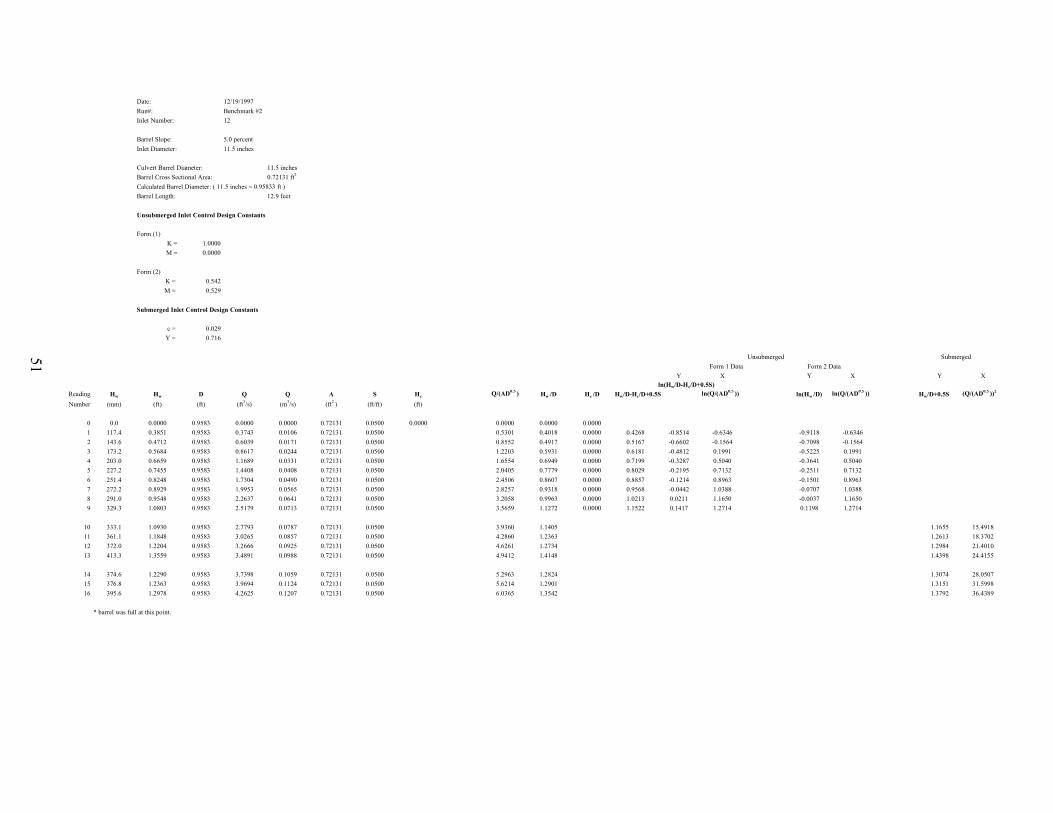
Date: 12/19/1997Run#: Benchmark #2Inlet Number: 12
Barrel Slope: 5.0 percentInlet Diameter: 11.5 inches
Culvert Barrel Diameter: 11.5 inchesBarrel Cross Sectional Area: 0.72131 ft2
Calculated Barrel Diameter: ( 11.5 inches = 0.95833 ft )Barrel Length: 12.9 feet
Unsubmerged Inlet Control Design Constants
Form (1)K = 1.0000M = 0.0000
Form (2)K = 0.542M = 0.529
Submerged Inlet Control Design Constants
c = 0.029Y = 0.716
Unsubmerged Submerged Form 1 Data Form 2 Data
Y X Y X Y Xln(Hw/D-Hc/D+0.5S)
Reading Hw Hw D Q Q A S Hc Q/(AD0.5 ) Hw /D Hc /D Hw/D-Hc/D+0.5S ln(Q/(AD0.5 )) ln(Hw /D) ln(Q/(AD0.5 )) Hw/D+0.5S (Q/(AD0.5 ))2
Number (mm) (ft) (ft) (ft3/s) (m3/s) (ft2 ) (ft/ft) (ft)
0 0.0 0.0000 0.9583 0.0000 0.0000 0.72131 0.0500 0.0000 0.0000 0.0000 0.00001 117.4 0.3851 0.9583 0.3743 0.0106 0.72131 0.0500 0.5301 0.4018 0.0000 0.4268 -0.8514 -0.6346 -0.9118 -0.63462 143.6 0.4712 0.9583 0.6039 0.0171 0.72131 0.0500 0.8552 0.4917 0.0000 0.5167 -0.6602 -0.1564 -0.7098 -0.15643 173.2 0.5684 0.9583 0.8617 0.0244 0.72131 0.0500 1.2203 0.5931 0.0000 0.6181 -0.4812 0.1991 -0.5225 0.19914 203.0 0.6659 0.9583 1.1689 0.0331 0.72131 0.0500 1.6554 0.6949 0.0000 0.7199 -0.3287 0.5040 -0.3641 0.50405 227.2 0.7455 0.9583 1.4408 0.0408 0.72131 0.0500 2.0405 0.7779 0.0000 0.8029 -0.2195 0.7132 -0.2511 0.71326 251.4 0.8248 0.9583 1.7304 0.0490 0.72131 0.0500 2.4506 0.8607 0.0000 0.8857 -0.1214 0.8963 -0.1501 0.89637 272.2 0.8929 0.9583 1.9953 0.0565 0.72131 0.0500 2.8257 0.9318 0.0000 0.9568 -0.0442 1.0388 -0.0707 1.03888 291.0 0.9548 0.9583 2.2637 0.0641 0.72131 0.0500 3.2058 0.9963 0.0000 1.0213 0.0211 1.1650 -0.0037 1.16509 329.3 1.0803 0.9583 2.5179 0.0713 0.72131 0.0500 3.5659 1.1272 0.0000 1.1522 0.1417 1.2714 0.1198 1.2714
10 333.1 1.0930 0.9583 2.7793 0.0787 0.72131 0.0500 3.9360 1.1405 1.1655 15.491811 361.1 1.1848 0.9583 3.0265 0.0857 0.72131 0.0500 4.2860 1.2363 1.2613 18.370212 372.0 1.2204 0.9583 3.2666 0.0925 0.72131 0.0500 4.6261 1.2734 1.2984 21.401013 413.3 1.3559 0.9583 3.4891 0.0988 0.72131 0.0500 4.9412 1.4148 1.4398 24.4155
14 374.6 1.2290 0.9583 3.7398 0.1059 0.72131 0.0500 5.2963 1.2824 1.3074 28.050715 376.8 1.2363 0.9583 3.9694 0.1124 0.72131 0.0500 5.6214 1.2901 1.3151 31.599816 395.6 1.2978 0.9583 4.2625 0.1207 0.72131 0.0500 6.0365 1.3542 1.3792 36.4389
* barrel was full at this point.

52
Date: 10/24/1997Run#: 13Reducer Number: 2 Inlet No. 13
Barrel Slope: 3.5 percentInlet Diameter: 11.5 inches/8.625 inches
Culvert Barrel Diameter: 8.625 inchesBarrel Cross Sectional Area: 0.4057 ft2
Calculated Barrel Diameter: ( 8.625 inches = 0.71875 ft )Barrel Length: 12 feet
Unsubmerged Inlet Control Design Constants
Form (1)K = 1.0000M = 0.0000
Form (2)K = 0.474M = 0.529
Submerged Inlet Control Design Constants
c = 0.0000Y = 0.0000
Definitions: Notes:
HW = Headwater depth above inlet control section invert, ft 1). For mitered inlets use +0.7S instead of -0.5S as the slope correction factorD = Interior height of culvert barrel, ft 2). For Unsubmerged Flow, HW/D<1.2HC = Specific head at critical depth (d + V2/2g), ft 3). For Submerged Flow, HW/D>1.5 Q = Discharge, ft3/s 4). For Unsubmerged Flow, Q/AD0.5 <3.5A = Full cross sectional area of culvert barrel, ft2 5). For Submerged Flow, Q/AD0.5-4.0S = Culvert barrel slope, ft/ft
K,M = Constants
Unsubmerged Submerged Form 1 Data Form 2 Data
Y X Y X Y Xln(Hw/D-Hc/D+0.5S)
Reading Hw Hw D Q Q A S Hc Q/(AD0.5 ) Hw /D Hc /D Hw/D-Hc/D+0.5S ln(Q/(AD0.5 )) ln(Hw /D) ln(Q/(AD0.5 )) Hw/D+0.5S (Q/(AD0.5 ))2
Number (mm) (ft) (ft) (ft3/s) (m3/s) (ft2 ) (ft/ft) (ft)
0 0.0 0.0000 0.9583 0.0000 0.0000 0.72131 0.0350 0.0000 0.0000 0.0000 0.00001 61.5 0.2018 0.9583 0.1413 0.0040 0.72131 0.0350 0.2091 0.2000 0.2105 0.2182 0.0098 -4.6215 -1.6092 -1.5581 -1.60922 103.2 0.3385 0.9583 0.4167 0.0118 0.72131 0.0350 0.3670 0.5901 0.3532 0.3829 -0.0122 #NUM! -0.5274 -1.0408 -0.52743 137.1 0.4498 0.9583 0.7381 0.0209 0.72131 0.0350 0.4979 1.0453 0.4694 0.5195 -0.0327 #NUM! 0.0443 -0.7564 0.04434 169.3 0.5553 0.9583 1.1866 0.0336 0.72131 0.0350 0.6465 1.6804 0.5795 0.6746 -0.0776 #NUM! 0.5190 -0.5456 0.51905 195.8 0.6425 0.9583 1.3843 0.0392 0.72131 0.0350 0.7053 1.9605 0.6704 0.7360 -0.0481 #NUM! 0.6732 -0.3998 0.67326 217.7 0.7141 0.9583 1.6033 0.0454 0.72131 0.0350 0.7675 2.2706 0.7452 0.8009 -0.0382 #NUM! 0.8200 -0.2941 0.82007 238.2 0.7816 0.9583 1.8823 0.0533 0.72131 0.0350 0.8434 2.6656 0.8156 0.8801 -0.0470 #NUM! 0.9804 -0.2038 0.98048 257.6 0.8450 0.9583 2.1648 0.0613 0.72131 0.0350 0.9177 3.0657 0.8818 0.9576 -0.0584 #NUM! 1.1203 -0.1258 1.12039 273.3 0.8967 0.9583 2.4226 0.0686 0.72131 0.0350 0.9841 3.4308 0.9356 1.0269 -0.0738 #NUM! 1.2328 -0.0665 1.2328
10* 358.9 1.1775 0.9583 3.4608 0.0980 0.72131 0.0350 4.9012 1.2287 1.2462 24.021711* 394.5 1.2943 0.9583 3.6939 0.1046 0.72131 0.0350 5.2313 1.3506 1.3681 27.366212* 457.5 1.5011 0.9583 3.9093 0.1107 0.72131 0.0350 5.5363 1.5664 1.5839 30.651113* 526.5 1.7273 0.9583 4.1142 0.1165 0.72131 0.0350 5.8264 1.8024 1.8199 33.9471
* barrel was full at this point

53
Date: 10/29/1997Run#: 14Reducer Number: 3 Inlet No. 13
Barrel Slope: 2.8 percentInlet Diameter: 11.5 inches/8.625 inches
Culvert Barrel Diameter: 8.625 inchesBarrel Cross Sectional Area: 0.4057 ft2
Calculated Barrel Diameter: ( 8.625 inches = 0.71875 ft )Barrel Length: 12 feet
Unsubmerged Inlet Control Design Constants
Form (1)K = 1.0000M = 0.0000
Form (2)K = 0.479M = 0.521
Submerged Inlet Control Design Constants
c = 0.0000Y = 0.0000
Definitions: Notes:
HW = Headwater depth above inlet control section invert, ft 1). For mitered inlets use +0.7S instead of -0.5S as the slope correction factorD = Interior height of culvert barrel, ft 2). For Unsubmerged Flow, HW/D<1.2HC = Specific head at critical depth (d + V2/2g), ft 3). For Submerged Flow, HW/D>1.5 Q = Discharge, ft3/s 4). For Unsubmerged Flow, Q/AD0.5 <3.5A = Full cross sectional area of culvert barrel, ft2 5). For Submerged Flow, Q/AD0.5-4.0S = Culvert barrel slope, ft/ft
K,M = Constants Unsubmerged Submerged Form 1 Data Form 2 Data
Y X Y X Y Xln(Hw/D-Hc/D+0.5S)
Reading Hw Hw D Q Q A S Hc Q/(AD0.5 ) Hw /D Hc /D Hw/D-Hc/D+0.5S ln(Q/(AD0.5 )) ln(Hw /D) ln(Q/(AD0.5 )) Hw/D+0.5S (Q/(AD0.5 ))2
Number (mm) (ft) (ft) (ft3/s) (m3/s) (ft2 ) (ft/ft) (ft)
0 0.0 0.0000 0.9583 0.0000 0.0000 0.72131 0.0280 0.0000 0.0000 0.0000 0.00001 56.8 0.1862 0.9583 0.1165 0.0033 0.72131 0.0280 0.1895 0.1650 0.1943 0.1977 0.0106 -4.5423 -1.8016 -1.6381 -1.80162 104.3 0.3422 0.9583 0.4202 0.0119 0.72131 0.0280 0.3686 0.5951 0.3571 0.3846 -0.0135 #NUM! -0.5190 -1.0298 -0.51903 138.4 0.4540 0.9583 0.7345 0.0208 0.72131 0.0280 0.4966 1.0403 0.4737 0.5182 -0.0305 #NUM! 0.0395 -0.7472 0.03954 171.3 0.5620 0.9583 1.1795 0.0334 0.72131 0.0280 0.6443 1.6704 0.5864 0.6723 -0.0719 #NUM! 0.5131 -0.5337 0.51315 197.0 0.6464 0.9583 1.3843 0.0392 0.72131 0.0280 0.7053 1.9605 0.6745 0.7360 -0.0475 #NUM! 0.6732 -0.3937 0.67326 219.7 0.7208 0.9583 1.6068 0.0455 0.72131 0.0280 0.7685 2.2756 0.7521 0.8019 -0.0358 #NUM! 0.8222 -0.2848 0.82227 241.2 0.7913 0.9583 1.8999 0.0538 0.72131 0.0280 0.8481 2.6907 0.8257 0.8850 -0.0453 #NUM! 0.9898 -0.1915 0.98988 261.5 0.8579 0.9583 2.1719 0.0615 0.72131 0.0280 0.9196 3.0757 0.8952 0.9595 -0.0503 #NUM! 1.1235 -0.1107 1.1235
9* 375.4 1.2316 0.9583 3.4608 0.0980 0.72131 0.0280 4.9012 1.2852 1.2992 24.021710* 428.2 1.4050 0.9583 3.7045 0.1049 0.72131 0.0280 5.2463 1.4661 1.4801 27.523411* 487.7 1.6001 0.9583 3.8952 0.1103 0.72131 0.0280 5.5163 1.6696 1.6836 30.430012* 561.8 1.8431 0.9583 4.1424 0.1173 0.72131 0.0280 5.8664 1.9232 1.9372 34.4150
* barrel was full at this point

54
Date: 11/6/1997Run#: 15Reducer Number: 10 Inlet No. 13
Barrel Slope: 2.0 percentInlet Diameter: 11.5 inches/10.0 inches
Culvert Barrel Diameter: 10.0 inchesBarrel Cross Sectional Area: 0.54542 ft2
Calculated Barrel Diameter: ( 10.0 inches = 0.8333 ft )Barrel Length: 12 feet
Unsubmerged Inlet Control Design Constants
Form (1)K = 1.0000M = 0.0000
Form (2)K = 0.467M = 0.558
Submerged Inlet Control Design Constants
c = 0.025Y = 0.648
Definitions: Notes:
HW = Headwater depth above inlet control section invert, ft 1). For mitered inlets use +0.7S instead of -0.5S as the slope correction factorD = Interior height of culvert barrel, ft 2). For Unsubmerged Flow, HW/D<1.2HC = Specific head at critical depth (d + V2/2g), ft 3). For Submerged Flow, HW/D>1.5 Q = Discharge, ft3/s 4). For Unsubmerged Flow, Q/AD0.5 <3.5A = Full cross sectional area of culvert barrel, ft2 5). For Submerged Flow, Q/AD0.5-4.0S = Culvert barrel slope, ft/ft
K,M = ConstantsUnsubmerged Submerged
Form 1 Data Form 2 DataY X Y X Y X
ln(Hw/D-Hc/D+0.5S)Reading Hw Hw D Q Q A S Hc Q/(AD0.5 ) Hw /D Hc /D Hw/D-Hc/D+0.5S ln(Q/(AD0.5 )) ln(Hw /D) ln(Q/(AD0.5 )) Hw/D+0.5S (Q/(AD0.5 ))2
Number (mm) (ft) (ft) (ft3/s) (m3/s) (ft2 ) (ft/ft) (ft)
0 0.0 0.0000 0.9583 0.0000 0.0000 0.72131 0.0200 0.0000 0.0000 0.0000 0.00001 75.5 0.2476 0.9583 0.2295 0.0065 0.72131 0.0200 0.2687 0.3251 0.2584 0.2804 -0.0120 #NUM! -1.1237 -1.3534 -1.12372 110.4 0.3621 0.9583 0.5015 0.0142 0.72131 0.0200 0.4047 0.7102 0.3778 0.4223 -0.0345 #NUM! -0.3422 -0.9733 -0.34223 148.7 0.4878 0.9583 0.8546 0.0242 0.72131 0.0200 0.5392 1.2103 0.5090 0.5626 -0.0437 #NUM! 0.1909 -0.6754 0.19094 177.2 0.5814 0.9583 1.2395 0.0351 0.72131 0.0200 0.6625 1.7554 0.6066 0.6914 -0.0747 #NUM! 0.5627 -0.4998 0.56275 202.1 0.6631 0.9583 1.4550 0.0412 0.72131 0.0200 0.7257 2.0605 0.6919 0.7572 -0.0554 #NUM! 0.7229 -0.3683 0.72296 225.7 0.7404 0.9583 1.6986 0.0481 0.72131 0.0200 0.7938 2.4056 0.7726 0.8283 -0.0457 #NUM! 0.8778 -0.2580 0.87787 244.3 0.8015 0.9583 1.9600 0.0555 0.72131 0.0200 0.8641 2.7757 0.8364 0.9016 -0.0553 #NUM! 1.0209 -0.1787 1.02098 265.3 0.8703 0.9583 2.2425 0.0635 0.72131 0.0200 0.9378 3.1758 0.9081 0.9786 -0.0605 #NUM! 1.1556 -0.0964 1.15569 280.1 0.9191 0.9583 2.4968 0.0707 0.72131 0.0200 1.0031 3.5359 0.9590 1.0467 -0.0776 #NUM! 1.2630 -0.0418 1.2630
10 299.0 0.9811 0.9583 2.7581 0.0781 0.72131 0.0200 3.9060 1.0237 1.0337 15.256411 315.5 1.0351 0.9583 2.9876 0.0846 0.72131 0.0200 4.2310 1.0801 1.0901 17.901612 342.5 1.1236 0.9583 3.2525 0.0921 0.72131 0.0200 4.6061 1.1724 1.1824 21.2163
13* 402.5 1.3205 0.9583 4.2766 0.1211 0.72131 0.0200 6.0565 1.3780 1.3880 36.6809
* barrel was full at this point

55
Date: 11/10/1997Run#: 16Reducer Number: 10 Inlet No. 13
Barrel Slope: 2.0 percentInlet Diameter: 11.5 inches/10.0 inches
Culvert Barrel Diameter: 10.0 inchesBarrel Cross Sectional Area: 0.54542 ft2
Calculated Barrel Diameter: ( 10.0 inches = 0.8333 ft )Barrel Length: 12 feet
Unsubmerged Inlet Control Design Constants
Form (1)K = 1.0000M = 0.0000
Form (2)K = 0.481M = 0.535
Submerged Inlet Control Design Constants
c = 0.025Y = 0.656
Definitions: Notes:
HW = Headwater depth above inlet control section invert, ft 1). For mitered inlets use +0.7S instead of -0.5S as the slope correction factorD = Interior height of culvert barrel, ft 2). For Unsubmerged Flow, HW/D<1.2HC = Specific head at critical depth (d + V2/2g), ft 3). For Submerged Flow, HW/D>1.5 Q = Discharge, ft3/s 4). For Unsubmerged Flow, Q/AD0.5 <3.5A = Full cross sectional area of culvert barrel, ft2 5). For Submerged Flow, Q/AD0.5-4.0S = Culvert barrel slope, ft/ft
K,M = ConstantsUnsubmerged Submerged
Form 1 Data Form 2 DataY X Y X Y X
ln(Hw/D-Hc/D+0.5S)Reading Hw Hw D Q Q A S Hc Q/(AD0.5 ) Hw /D Hc /D Hw/D-Hc/D+0.5S ln(Q/(AD0.5 )) ln(Hw /D) ln(Q/(AD0.5 )) Hw/D+0.5S (Q/(AD0.5 ))2
Number (mm) (ft) (ft) (ft3/s) (m3/s) (ft2 ) (ft/ft) (ft)
0 0.0 0.0000 0.9583 0.0000 0.0000 0.72131 0.0200 0.0000 0.0000 0.0000 0.00001 80.6 0.2645 0.9583 0.2331 0.0066 0.72131 0.0200 0.2708 0.3301 0.2760 0.2826 0.0035 -5.6675 -1.1084 -1.2872 -1.10842 109.9 0.3607 0.9583 0.4662 0.0132 0.72131 0.0200 0.3894 0.6602 0.3764 0.4063 -0.0199 #NUM! -0.4153 -0.9772 -0.41533 145.5 0.4774 0.9583 0.7946 0.0225 0.72131 0.0200 0.5182 1.1253 0.4981 0.5407 -0.0326 #NUM! 0.1180 -0.6969 0.11804 171.2 0.5618 0.9583 1.0771 0.0305 0.72131 0.0200 0.6125 1.5254 0.5862 0.6391 -0.0429 #NUM! 0.4222 -0.5341 0.42225 199.0 0.6530 0.9583 1.3561 0.0384 0.72131 0.0200 0.6971 1.9205 0.6814 0.7274 -0.0360 #NUM! 0.6526 -0.3836 0.65266 221.0 0.7251 0.9583 1.6351 0.0463 0.72131 0.0200 0.7763 2.3156 0.7566 0.8101 -0.0435 #NUM! 0.8397 -0.2789 0.83977 241.5 0.7923 0.9583 1.9247 0.0545 0.72131 0.0200 0.8547 2.7257 0.8268 0.8919 -0.0551 #NUM! 1.0027 -0.1902 1.00278 262.6 0.8615 0.9583 2.1930 0.0621 0.72131 0.0200 0.9251 3.1058 0.8990 0.9653 -0.0563 #NUM! 1.1333 -0.1065 1.13339 277.7 0.9110 0.9583 2.4650 0.0698 0.72131 0.0200 0.9950 3.4908 0.9506 1.0382 -0.0776 #NUM! 1.2501 -0.0507 1.2501
10 297.1 0.9748 0.9583 2.7228 0.0771 0.72131 0.0200 3.8559 1.0172 1.0272 14.868311 316.6 1.0387 0.9583 2.9841 0.0845 0.72131 0.0200 4.2260 1.0839 1.0939 17.859312 339.5 1.1140 0.9583 3.2136 0.0910 0.72131 0.0200 4.5511 1.1624 1.1724 20.7126
13* 403.0 1.3221 0.9583 4.2590 0.1206 0.72131 0.0200 6.0315 1.3796 1.3896 36.3786
* barrel was full at this point

56
Date: 11/5/1997Run#: 17Reducer Number: 11 Inlet No. 13
Barrel Slope: 2.0 percentInlet Diameter: 11.5 inches/10.0 inches
Culvert Barrel Diameter: 10.0 inchesBarrel Cross Sectional Area: 0.54542 ft2
Calculated Barrel Diameter: ( 10.0 inches = 0.8333 ft )Barrel Length: 12 feet
Unsubmerged Inlet Control Design Constants
Form (1)K = 1.0000M = 0.0000
Form (2)K = 0.482M = 0.529
Submerged Inlet Control Design Constants
c = 0.025Y = 0.654
Definitions: Notes:
HW = Headwater depth above inlet control secion invert, ft 1). For mitered inlets use +0.7S instead of -0.5S as the slope correction factorD = Interior height of culvert barrel, ft 2). For Unsubmerged Flow, HW/D<1.2HC = Specific head at critical depth (d + V2/2g), ft 3). For Submerged Flow, HW/D>1.5 Q = Discharge, ft3/s 4). For Unsubmerged Flow, Q/AD0.5 <3.5A = Full cross sectional area of culvert barrel, ft2 5) For Submerged Flow, Q/AD0.5-4.0S = Culvert barrel slope, ft/ft
K,M = ConstantsUnsubmerged Submerged
Form 1 Data Form 2 DataY X Y X Y X
ln(Hw/D-Hc/D+0.5S)Reading Hw Hw D Q Q A S Hc Q/(AD0.5 ) Hw /D Hc /D Hw/D-Hc/D+0.5S ln(Q/(AD0.5 )) ln(Hw /D) ln(Q/(AD0.5 )) Hw/D+0.5S (Q/(AD0.5 ))2
Number (mm) (ft) (ft) (ft3/s) (m3/s) (ft2 ) (ft/ft) (ft)
0 0.0 0.0000 0.9583 0.0000 0.0000 0.72131 0.0200 0.0000 0.0000 0.0000 0.00001 75.4 0.2474 0.9583 0.2013 0.0057 0.72131 0.0200 0.2510 0.2851 0.2581 0.2619 0.0062 -5.0817 -1.2550 -1.3543 -1.25502 107.7 0.3532 0.9583 0.4450 0.0126 0.72131 0.0200 0.3799 0.6302 0.3686 0.3964 -0.0178 #NUM! -0.4618 -0.9981 -0.46183 153.4 0.5034 0.9583 0.8723 0.0247 0.72131 0.0200 0.5452 1.2353 0.5253 0.5690 -0.0337 #NUM! 0.2113 -0.6438 0.21134 179.3 0.5881 0.9583 1.2395 0.0351 0.72131 0.0200 0.6625 1.7554 0.6137 0.6914 -0.0676 #NUM! 0.5627 -0.4882 0.56275 203.4 0.6672 0.9583 1.3949 0.0395 0.72131 0.0200 0.7084 1.9755 0.6962 0.7392 -0.0330 #NUM! 0.6808 -0.3621 0.68086 225.2 0.7390 0.9583 1.6845 0.0477 0.72131 0.0200 0.7899 2.3856 0.7711 0.8243 -0.0432 #NUM! 0.8694 -0.2600 0.86947 244.3 0.8015 0.9583 1.9529 0.0553 0.72131 0.0200 0.8622 2.7657 0.8364 0.8997 -0.0533 #NUM! 1.0173 -0.1787 1.01738 262.6 0.8614 0.9583 2.2354 0.0633 0.72131 0.0200 0.9360 3.1658 0.8989 0.9767 -0.0678 #NUM! 1.1524 -0.1066 1.15249 281.5 0.9237 0.9583 2.4968 0.0707 0.72131 0.0200 1.0031 3.5359 0.9638 1.0467 -0.0728 #NUM! 1.2630 -0.0368 1.2630
10 298.8 0.9803 0.9583 2.7298 0.0773 0.72131 0.0200 3.8659 1.0229 1.0329 14.945511 319.5 1.0482 0.9583 2.9912 0.0847 0.72131 0.0200 4.2360 1.0938 1.1038 17.944012 343.7 1.1275 0.9583 3.2384 0.0917 0.72131 0.0200 4.5861 1.1765 1.1865 21.0325
13* 404.8 1.3280 0.9583 4.2660 0.1208 0.72131 0.0200 6.0415 1.3857 1.3957 36.4994
"*" means that the barrel was full at this point.

57
Date: 12/30/1997Run#: Headwall #1Inlet Description: Square Edge w/ Headwall
Barrel Slope: 3.5 percentInlet Diameter: 11.5 inches
Culvert Barrel Diameter: 11.5 inchesBarrel Cross Sectional Area: 0.72131 ft2
Calculated Barrel Diameter: ( 11.5 inches = 0.95833 ft )Barrel Length: 12.9 feet
Unsubmerged Inlet Control Design Constants
Form (1)K = 1.0000M = 0.0000
Form (2)K = 0.574M = 0.543
Submerged Inlet Control Design Constants
c = 0.038Y = 0.734
Definitions: Notes:
HW = Headwater depth above inlet control section invert, ft 1). For mitered inlets use +0.7S instead of -0.5S as the slope correction factorD = Interior height of culvert barrel, ft 2). For Unsubmerged Flow, HW/D<1.2HC = Specific head at critical depth (d + V2/2g), ft 3). For Submerged Flow, HW/D>1.5 Q = Discharge, ft3/s 4). For Unsubmerged Flow, Q/AD0.5 <3.5A = Full cross sectional area of culvert barrel, ft2 5). For Submerged Flow, Q/AD0.5-4.0S = Culvert barrel slope, ft/ft
K,M = ConstantsUnsubmerged Submerged
Form 1 Data Form 2 DataY X Y X Y X
ln(Hw/D-Hc/D+0.5S)Reading Hw Hw D Q Q A S Hc Q/(AD0.5 ) Hw /D Hc /D Hw/D-Hc/D+0.5S ln(Q/(AD0.5 )) ln(Hw /D) ln(Q/(AD0.5 )) Hw/D+0.5S (Q/(AD0.5 ))2
Number (mm) (ft) (ft) (ft3/s) (m3/s) (ft2 ) (ft/ft) (ft)
0 0.0 0.0000 0.9583 0.0000 0.0000 0.72131 0.0350 0.0000 0.0000 0.0000 0.00001 107.9 0.3541 0.9583 0.2931 0.0083 0.72131 0.0350 0.4151 0.3695 0.0000 0.3870 -0.9493 -0.8792 -0.9956 -0.87922 140.5 0.4611 0.9583 0.5156 0.0146 0.72131 0.0350 0.7302 0.4811 0.0000 0.4986 -0.6959 -0.3145 -0.7317 -0.31453 175.6 0.5761 0.9583 0.7910 0.0224 0.72131 0.0350 1.1203 0.6012 0.0000 0.6187 -0.4802 0.1136 -0.5089 0.11364 210.0 0.6889 0.9583 1.2184 0.0345 0.72131 0.0350 1.7254 0.7188 0.0000 0.7363 -0.3061 0.5455 -0.3301 0.54555 236.6 0.7761 0.9583 1.3561 0.0384 0.72131 0.0350 1.9205 0.8099 0.0000 0.8274 -0.1895 0.6526 -0.2109 0.65266 261.9 0.8594 0.9583 1.6315 0.0462 0.72131 0.0350 2.3106 0.8967 0.0000 0.9142 -0.0897 0.8375 -0.1090 0.83757 289.6 0.9502 0.9583 1.9141 0.0542 0.72131 0.0350 2.7107 0.9916 0.0000 1.0091 0.0090 0.9972 -0.0085 0.99728 316.8 1.0395 0.9583 2.1930 0.0621 0.72131 0.0350 3.1058 1.0847 0.0000 1.1022 0.0973 1.1333 0.0813 1.13339 344.3 1.1295 0.9583 2.4508 0.0694 0.72131 0.0350 3.4708 1.1786 0.0000 1.1961 0.1791 1.2444 0.1643 1.2444
10 370.2 1.2147 0.9583 2.7051 0.0766 0.72131 0.0350 3.8309 1.2675 1.2850 14.676011 405.9 1.3316 0.9583 2.9629 0.0839 0.72131 0.0350 4.1960 1.3895 1.4070 17.606612 438.9 1.4399 0.9583 3.2101 0.0909 0.72131 0.0350 4.5461 1.5025 1.5200 20.667113 472.3 1.5497 0.9583 3.4361 0.0973 0.72131 0.0350 4.8662 1.6170 1.6345 23.679714 508.0 1.6666 0.9583 3.6727 0.1040 0.72131 0.0350 5.2013 1.7390 1.7565 27.053215 547.8 1.7972 0.9583 3.9093 0.1107 0.72131 0.0350 5.5363 1.8754 1.8929 30.651116 600.1 1.9688 0.9583 4.1919 0.1187 0.72131 0.0350 5.9364 2.0544 2.0719 35.2414
* barrel was full at this point

58
Date: 12/18/1997Run#: Benchmark #1Inlet Number: 12
Barrel Slope: 3.5 percentInlet Diameter: 11.5 inches
Culvert Barrel Diameter: 11.5 inchesBarrel Cross Sectional Area: 0.72131 ft2
Calculated Barrel Diameter: ( 11.5 inches = 0.95833 ft )Barrel Length: 12.9 feet
Unsubmerged Inlet Control Design Constants
Form (1)K = 1.0000M = 0.0000
Form (2)K = 0.512M = 0.562
Submerged Inlet Control Design Constants
c = 0.0000Y = 0.0000
Definitions: Notes:
HW = Headwater depth above inlet control section invert, ft 1). For mitered inlets use +0.7S instead of -0.5S as the slope correction factorD = Interior height of culvert barrel, ft 2). For Unsubmerged Flow, HW/D<1.2HC = Specific head at critical depth (d + V2/2g), ft 3). For Submerged Flow, HW/D>1.5 Q = Discharge, ft3/s 4). For Unsubmerged Flow, Q/AD0.5 <3.5A = Full cross sectional area of culvert barrel, ft2 5). For Submerged Flow, Q/AD0.5-4.0S = Culvert barrel slope, ft/ft
K,M = ConstantsUnsubmerged Submerged
Form 1 Data Form 2 DataY X Y X Y X
ln(Hw/D-Hc/D+0.5S)Reading Hw Hw D Q Q A S Hc Q/(AD0.5 ) Hw /D Hc /D Hw/D-Hc/D+0.5S ln(Q/(AD0.5 )) ln(Hw /D) ln(Q/(AD0.5 )) Hw/D+0.5S (Q/(AD0.5 ))2
Number (mm) (ft) (ft) (ft3/s) (m3/s) (ft2 ) (ft/ft) (ft)
0 0.0 0.0000 0.9583 0.0000 0.0000 0.72131 0.0350 0.0000 0.0000 0.0000 0.00001 73.3 0.2406 0.9583 0.1907 0.0054 0.72131 0.0350 0.2701 0.2511 0.0000 0.2686 -1.3147 -1.3091 -1.3821 -1.30912 115.9 0.3801 0.9583 0.4626 0.0131 0.72131 0.0350 0.6552 0.3967 0.0000 0.4142 -0.8815 -0.4229 -0.9247 -0.42293 159.3 0.5227 0.9583 0.7840 0.0222 0.72131 0.0350 1.1103 0.5455 0.0000 0.5630 -0.5745 0.1046 -0.6061 0.10464 192.4 0.6313 0.9583 1.2360 0.0350 0.72131 0.0350 1.7504 0.6588 0.0000 0.6763 -0.3911 0.5599 -0.4173 0.55995 218.9 0.7182 0.9583 1.3879 0.0393 0.72131 0.0350 1.9655 0.7494 0.0000 0.7669 -0.2654 0.6757 -0.2885 0.67576 243.6 0.7991 0.9583 1.6598 0.0470 0.72131 0.0350 2.3506 0.8338 0.0000 0.8513 -0.1609 0.8547 -0.1817 0.85477 266.4 0.8741 0.9583 1.9317 0.0547 0.72131 0.0350 2.7357 0.9121 0.0000 0.9296 -0.0730 1.0064 -0.0920 1.00648 288.6 0.9469 0.9583 2.2284 0.0631 0.72131 0.0350 3.1558 0.9880 0.0000 1.0055 0.0055 1.1492 -0.0121 1.14929 309.9 1.0168 0.9583 2.4862 0.0704 0.72131 0.0350 3.5209 1.0611 0.0000 1.0786 0.0756 1.2587 0.0593 1.2587
10 332.1 1.0897 0.9583 2.7192 0.0770 0.72131 0.0350 3.8509 1.1371 1.1546 14.829711 358.7 1.1767 0.9583 2.9594 0.0838 0.72131 0.0350 4.1910 1.2279 1.2454 17.5646
"*" means that the barrel was full at this point.

59
Date: 12/24/1997Run#: Benchmark #3Inlet Number: 13
Barrel Slope: 3.5 percentInlet Diameter: 11.5 inches
Culvert Barrel Diameter: 11.5 inchesBarrel Cross Sectional Area: 0.72131 ft2
Calculated Barrel Diameter: ( 11.5 inches = 0.95833 ft )Barrel Length: 12.9 feet
Unsubmerged Inlet Control Design Constants
Form (1)K = 1.0000M = 0.0000
Form (2)K = 0.499M = 0.566
Submerged Inlet Control Design Constants
c = 0.015Y = 0.924
Definitions: Notes:
HW = Headwater depth above inlet control section invert, ft 1). For mitered inlets use +0.7S instead of -0.5S as the slope correction factorD = Interior height of culvert barrel, ft 2). For Unsubmerged Flow, HW/D<1.2HC = Specific head at critical depth (d + V2/2g), ft 3). For Submerged Flow, HW/D>1.5 Q = Discharge, ft3/s 4). For Unsubmerged Flow, Q/AD0.5 <3.5A = Full cross sectional area of culvert barrel, ft2 5). For Submerged Flow, Q/AD0.5-4.0S = Culvert barrel slope, ft/ft
K,M = ConstantsUnsubmerged Submerged
Form 1 Data Form 2 DataY X Y X Y X
ln(Hw/D-Hc/D+0.5S)Reading Hw Hw D Q Q A S Hc Q/(AD0.5 ) Hw /D Hc /D Hw/D-Hc/D+0.5S ln(Q/(AD0.5 )) ln(Hw /D) ln(Q/(AD0.5 )) Hw/D+0.5S (Q/(AD0.5 ))2
Number (mm) (ft) (ft) (ft3/s) (m3/s) (ft2 ) (ft/ft) (ft)
0 0.0 0.0000 0.9583 0.0000 0.0000 0.72131 0.0350 0.0000 0.0000 0.0000 0.00001 93.3 0.3060 0.9583 0.2755 0.0078 0.72131 0.0350 0.3901 0.3193 0.0000 0.3368 -1.0883 -0.9414 -1.1416 -0.94142 119.3 0.3913 0.9583 0.6215 0.0176 0.72131 0.0350 0.8802 0.4083 0.0000 0.4258 -0.8538 -0.1276 -0.8957 -0.12763 155.2 0.5091 0.9583 0.7840 0.0222 0.72131 0.0350 1.1103 0.5312 0.0000 0.5487 -0.6002 0.1046 -0.6326 0.10464 186.0 0.6103 0.9583 1.1724 0.0332 0.72131 0.0350 1.6604 0.6369 0.0000 0.6544 -0.4241 0.5071 -0.4512 0.50715 213.6 0.7008 0.9583 1.3561 0.0384 0.72131 0.0350 1.9205 0.7313 0.0000 0.7488 -0.2893 0.6526 -0.3130 0.65266 238.7 0.7831 0.9583 1.6457 0.0466 0.72131 0.0350 2.3306 0.8172 0.0000 0.8347 -0.1807 0.8461 -0.2019 0.84617 262.9 0.8624 0.9583 1.9388 0.0549 0.72131 0.0350 2.7457 0.8999 0.0000 0.9174 -0.0862 1.0100 -0.1054 1.01008 281.3 0.9228 0.9583 2.1824 0.0618 0.72131 0.0350 3.0908 0.9629 0.0000 0.9804 -0.0198 1.1284 -0.0378 1.12849 303.4 0.9955 0.9583 2.4720 0.0700 0.72131 0.0350 3.5009 1.0388 0.0000 1.0563 0.0548 1.2530 0.0381 1.2530
10 324.5 1.0646 0.9583 2.7086 0.0767 0.72131 0.0350 3.8359 1.1109 1.1284 14.714411 344.8 1.1311 0.9583 2.9558 0.0837 0.72131 0.0350 4.1860 1.1803 1.1978 17.522712 352.2 1.1556 0.9583 3.2136 0.0910 0.72131 0.0350 4.5511 1.2059 1.2234 20.712613 367.5 1.2058 0.9583 3.4750 0.0984 0.72131 0.0350 4.9212 1.2582 1.2757 24.2182
* barrel was full at this point

60
Inlet Diameter: 11.5 inches
Culvert Barrel Diameter: 11.5 inchesBarrel Cross Sectional Area: 0.72131 ft2
Calculated Barrel Diameter: ( 11.5 inches = 0.95833 ft )Barrel Length: 12.9 feet
Unsubmerged Inlet Control Design Constants
Form (1)K = 1.0000M = 0.0000
Form (2)K = 0.491M = 0.564
Submerged Inlet Control Design Constants
c = 0.019Y = 0.830
Definitions: Notes:
HW = Headwater depth above inlet control section invert, ft 1). For mitered inlets use +0.7S instead of -0.5S as the slope correction factorD = Interior height of culvert barrel, ft 2). For Unsubmerged Flow, HW/D<1.2HC = Specific head at critical depth (d + V2/2g), ft 3). For Submerged Flow, HW/D>1.5 Q = Discharge, ft3/s 4). For Unsubmerged Flow, Q/AD0.5 <3.5A = Full cross sectional area of culvert barrel, ft2 5). For Submerged Flow, Q/AD0.5-4.0S = Culvert barrel slope, ft/ft
K,M = ConstantsUnsubmerged Submerged
Form 1 Data Form 2 DataY X Y X Y X
ln(Hw/D-Hc/D+0.5S)Reading Hw Hw D Q Q A S Hc Q/(AD0.5 ) Hw /D Hc /D Hw/D-Hc/D+0.5S ln(Q/(AD0.5 )) ln(Hw /D) ln(Q/(AD0.5 )) Hw/D+0.5S (Q/(AD0.5 ))2
Number (mm) (ft) (ft) (ft3/s) (m3/s) (ft2 ) (ft/ft) (ft)
0 0.0 0.0000 0.9583 0.0000 0.0000 0.72131 0.0500 0.0000 0.0000 0.0000 0.00001 87.6 0.2875 0.9583 0.2860 0.0081 0.72131 0.0500 0.4051 0.3000 0.0000 0.3250 -1.1239 -0.9036 -1.2039 -0.90362 121.8 0.3995 0.9583 0.5438 0.0154 0.72131 0.0500 0.7702 0.4169 0.0000 0.4419 -0.8167 -0.2611 -0.8750 -0.26113 152.1 0.4990 0.9583 0.7946 0.0225 0.72131 0.0500 1.1253 0.5207 0.0000 0.5457 -0.6057 0.1180 -0.6526 0.11804 183.9 0.6035 0.9583 1.1018 0.0312 0.72131 0.0500 1.5604 0.6297 0.0000 0.6547 -0.4236 0.4449 -0.4625 0.44495 209.6 0.6877 0.9583 1.3914 0.0394 0.72131 0.0500 1.9705 0.7176 0.0000 0.7426 -0.2976 0.6783 -0.3319 0.67836 234.1 0.7682 0.9583 1.6845 0.0477 0.72131 0.0500 2.3856 0.8016 0.0000 0.8266 -0.1905 0.8694 -0.2212 0.86947 253.8 0.8328 0.9583 1.9458 0.0551 0.72131 0.0500 2.7557 0.8690 0.0000 0.8940 -0.1121 1.0137 -0.1404 1.01378 272.7 0.8947 0.9583 2.2142 0.0627 0.72131 0.0500 3.1358 0.9336 0.0000 0.9586 -0.0423 1.1429 -0.0687 1.14299 295.7 0.9700 0.9583 2.4897 0.0705 0.72131 0.0500 3.5259 1.0122 0.0000 1.0372 0.0365 1.2601 0.0121 1.2601
10 316.9 1.0396 0.9583 2.7475 0.0778 0.72131 0.0500 3.8909 1.0848 1.1098 15.139511 338.4 1.1103 0.9583 3.0053 0.0851 0.72131 0.0500 4.2560 1.1586 1.1836 18.113812 349.6 1.1471 0.9583 3.2419 0.0918 0.72131 0.0500 4.5911 1.1969 1.2219 21.0784
* barrel was full at this point.

61
Date: 10/31/1997 Reading # Q Headbox Projected He Ke = Average AverageRun#: 19 (cms) EGL EGL (mm) 2g/V2*He He KeData Collected By: CRW 1* 0.008 1014.1 1012.1 2.03 0.86Inlet Description: # 13 2* 0.017 1036.5 1034.7 1.72 0.16 25.87 0.17
3* 0.028 1074.2 1070.9 3.30 0.12Barrel Slope: 2.80% 4* 0.037 1114.6 1109.1 5.56 0.12 Average AverageInlet Diameter: 11.5 inches 5 0.043 1153.6 1142.4 11.17 0.17 He (no f) KeBarrel Length: 12 feet 6 0.054 1220.4 1201.1 19.31 0.18Barrel Area: 0.0377 7 0.065 1300.4 1273.6 26.78 0.17 19.76 0.13Culvert Barrel Dia: 219.1 mm = 8.625 in. 8 0.074 1370.0 1336.2 33.72 0.17Reducer # : 1 9 0.084 1447.9 1409.5 38.39 0.15Reducer length : 34.0 inches
* not included in the average
Reading # Q He total Hf elbow Hf reducer He (no f) Ke (no f)=(cms) (mm) (mm) (mm) (mm) 2g/V2*He
5 0.043 11.17 0.65 2.16 8.36 0.126 0.054 19.31 0.95 3.15 15.21 0.147 0.065 26.78 1.50 4.97 20.32 0.138 0.074 33.72 1.79 5.95 25.98 0.139 0.084 38.39 2.19 7.25 28.95 0.12
Cum. Hor. Cum. Hor.Reading # Port # HGL Q A V=Q/A V2/2g Cum. Hor. Dist. w/out EGL Reading # Port # HGL Q A V=Q/A V2/2g Cum. Hor. Dist. w/out EGL
(mm) (m3/s) (m2) (m/s) (mm) Distance elbow + red HGL+V2/2g (mm) (m3/s) (m2) (m/s) (mm) Distance elbow + red HGL+V2/2g (mm) (mm) (ft) (mm) (mm) (mm)
1 1 1014.6 0.0 1014.6 7 1 1298.5 0.0 1298.52 1014.1 0.0 1014.1 2 1301.1 0.0 1301.13 1013.6 0.0 1013.6 3 1301.5 0.0 1301.5
3.5 1012.2 0.0081 0.067 0.121 0.745 63.4 1012.9 3.5 1226.3 0.0654 0.067 0.976 48.6 63.4 1274.94 1012.1 0.0081 0.067 0.121 0.745 149.4 1012.8 4 1228 0.0654 0.067 0.976 48.6 149.4 1276.65 1012.4 0.0081 0.067 0.121 0.745 292.6 1013.1 5 1249.9 0.0654 0.067 0.976 48.6 292.6 1298.56 1012.1 0.0081 0.067 0.121 0.745 433.4 1012.8 6 1250.3 0.0654 0.067 0.976 48.6 433.4 1298.97 1011.8 0.0081 0.061 0.132 0.890 674.8 1012.7 7 1230.9 0.0654 0.061 1.067 58.0 674.8 1288.9
7.5 1011.0 0.0081 0.051 0.158 1.271 960.6 1012.3 7.5 1193.7 0.0654 0.051 1.275 82.8 960.6 1276.58 1010.6 0.0081 0.042 0.193 1.896 1252.7 1012.5 8 1149.1 0.0654 0.042 1.557 123.6 1252.7 1272.79 1009.6 0.0081 0.038 0.215 2.353 2008.2 609.6 1012.0 9 1113.4 0.0654 0.038 1.735 153.4 2008.2 609.6 1266.8
10 1009.0 0.0081 0.038 0.215 2.353 2617.8 1219.2 1011.4 10 1099.5 0.0654 0.038 1.735 153.4 2617.8 1219.2 1252.911 1008.4 0.0081 0.038 0.215 2.353 3176.6 1778.0 1010.8 11 1103.0 0.0654 0.038 1.735 153.4 3176.6 1778.0 1256.412 1008.5 0.0081 0.038 0.215 2.353 3837.0 2438.4 1010.9 12 1087.6 0.0654 0.038 1.735 153.4 3837.0 2438.4 1241.013 1008.2 0.0081 0.038 0.215 2.353 4446.6 3048.0 1010.6 13 1080.3 0.0654 0.038 1.735 153.4 4446.6 3048.0 1233.7
Cum. Hor. Cum. Hor.Reading # Port # HGL Q A V=Q/A V2/2g Cum. Hor. Dist. w/out EGL Reading # Port # HGL Q A V=Q/A V2/2g Cum. Hor. Dist. w/out EGL
(mm) (m3/s) (m2) (m/s) (mm) Distance elbow + red HGL+V2/2g (mm) (m3/s) (m2) (m/s) (mm) Distance elbow + red HGL+V2/2g (mm) (mm) (ft) (mm) (mm) (mm)
2 1 1036.6 0.0 1036.6 8 1 1367.5 0.0 1367.52 1036.1 0.0 1036.1 2 1370.8 0.0 1370.83 1036.7 0.0 1036.7 3 1371.6 0.0 1371.6
3.5 1032.3 0.0171 0.067 0.255 3.320 63.4 1035.6 3.5 1275 0.0744 0.067 1.110 62.8 63.4 1337.84 1031.2 0.0171 0.067 0.255 3.320 149.4 1034.5 4 1277.9 0.0744 0.067 1.110 62.8 149.4 1340.75 1033.6 0.0171 0.067 0.255 3.320 292.6 1036.9 5 1304.7 0.0744 0.067 1.110 62.8 292.6 1367.56 1032.8 0.0171 0.067 0.255 3.320 433.4 1036.1 6 1305.7 0.0744 0.067 1.110 62.8 433.4 1368.57 1031.2 0.0171 0.061 0.279 3.966 674.8 1035.2 7 1279.7 0.0744 0.061 1.214 75.1 674.8 1354.8
7.5 1028.2 0.0171 0.051 0.333 5.663 960.6 1033.9 7.5 1230.3 0.0744 0.051 1.450 107.2 960.6 1337.58 1026.2 0.0171 0.042 0.407 8.449 1252.7 1034.6 8 1172.5 0.0744 0.042 1.771 159.9 1252.7 1332.49 1023.8 0.0171 0.038 0.454 10.486 2008.2 609.6 1034.3 9 1129.4 0.0744 0.038 1.973 198.5 2008.2 609.6 1327.9
10 1022.6 0.0171 0.038 0.454 10.486 2617.8 1219.2 1033.1 10 1112.0 0.0744 0.038 1.973 198.5 2617.8 1219.2 1310.511 1022.3 0.0171 0.038 0.454 10.486 3176.6 1778.0 1032.8 11 1118.4 0.0744 0.038 1.973 198.5 3176.6 1778.0 1316.912 1021.7 0.0171 0.038 0.454 10.486 3837.0 2438.4 1032.2 12 1099.8 0.0744 0.038 1.973 198.5 3837.0 2438.4 1298.313 1020.9 0.0171 0.038 0.454 10.486 4446.6 3048.0 1031.4 13 1088.8 0.0744 0.038 1.973 198.5 4446.6 3048.0 1287.3
Cum. Hor. Cum. Hor.Reading # Port # HGL Q A V=Q/A V2/2g Cum. Hor. Dist. w/out EGL Reading # Port # HGL Q A V=Q/A V2/2g Cum. Hor. Dist. w/out EGL
(mm) (m3/s) (m2) (m/s) (mm) Distance elbow + red HGL+V2/2g (mm) (m3/s) (m2) (m/s) (mm) Distance elbow + red HGL+V2/2g (mm) (mm) (ft) (mm) (mm) (mm)
3 1 1074.3 0.0 1074.3 9 1 1445.8 0.0 1445.82 1074 0.0 1074.0 2 1448.5 0.0 1448.53 1074.3 0.0 1074.3 3 1449.4 0.0 1449.4
3.5 1061.7 0.0275 0.067 0.410 8.587 63.4 1070.3 3.5 1327.2 0.0836 0.067 1.248 79.4 63.4 1406.64 1062 0.0275 0.067 0.410 8.587 149.4 1070.6 4 1328 0.0836 0.067 1.248 79.4 149.4 1407.45 1065.8 0.0275 0.067 0.410 8.587 292.6 1074.4 5 1365.8 0.0836 0.067 1.248 79.4 292.6 1445.26 1066.1 0.0275 0.067 0.410 8.587 433.4 1074.7 6 1367.9 0.0836 0.067 1.248 79.4 433.4 1447.37 1062.9 0.0275 0.061 0.449 10.258 674.8 1073.2 7 1332.4 0.0836 0.061 1.364 94.8 674.8 1427.2
7.5 1055.9 0.0275 0.051 0.536 14.646 960.6 1070.5 7.5 1270.3 0.0836 0.051 1.630 135.4 960.6 1405.78 1048.8 0.0275 0.042 0.655 21.851 1252.7 1070.7 8 1201.5 0.0836 0.042 1.990 201.9 1252.7 1403.49 1042.6 0.0275 0.038 0.729 27.120 2008.2 609.6 1069.7 9 1147.8 0.0836 0.038 2.218 250.6 2008.2 609.6 1398.4
10 1039.6 0.0275 0.038 0.729 27.120 2617.8 1219.2 1066.7 10 1128.0 0.0836 0.038 2.218 250.6 2617.8 1219.2 1378.611 1040.5 0.0275 0.038 0.729 27.120 3176.6 1778.0 1067.6 11 1136.5 0.0836 0.038 2.218 250.6 3176.6 1778.0 1387.112 1037.6 0.0275 0.038 0.729 27.120 3837.0 2438.4 1064.7 12 1112.2 0.0836 0.038 2.218 250.6 3837.0 2438.4 1362.813 1036.1 0.0275 0.038 0.729 27.120 4446.6 3048.0 1063.2 13 1098.8 0.0836 0.038 2.218 250.6 4446.6 3048.0 1349.4
Cum. Hor.Reading # Port # HGL Q A V=Q/A V2/2g Cum. Hor. Dist. w/out EGL
(mm) (m3/s) (m2) (m/s) (mm) Distance elbow + red HGL+V2/2g (mm) (mm) (ft)
4 1 1114.3 0.0 1114.32 1114.7 0.0 1114.73 1114.9 0.0 1114.9
3.5 1092.2 0.0365 0.067 0.545 15.126 63.4 1107.34 1092.3 0.0365 0.067 0.545 15.126 149.4 1107.45 1100.2 0.0365 0.067 0.545 15.126 292.6 1115.36 1100.2 0.0365 0.067 0.545 15.126 433.4 1115.37 1094.0 0.0365 0.061 0.595 18.070 674.8 1112.1
7.5 1082.2 0.0365 0.051 0.712 25.802 960.6 1108.08 1068.9 0.0365 0.042 0.869 38.494 1252.7 1107.49 1059.2 0.0365 0.038 0.968 47.775 2008.2 609.6 1107.0
10 1055.0 0.0365 0.038 0.968 47.775 2617.8 1219.2 1102.811 1054.9 0.0365 0.038 0.968 47.775 3176.6 1778.0 1102.712 1051.6 0.0365 0.038 0.968 47.775 3837.0 2438.4 1099.413 1048.4 0.0365 0.038 0.968 47.775 4446.6 3048.0 1096.2

62
Reading # Port # HGL Q A V=Q/A V2/2g Cum. Hor. Dist. w/out EGL(mm) (m3/s) (m2) (m/s) (mm) Distance elbow + red HGL+V2/2g
(mm) (mm) (ft)5 1 1153.3 0.0 1153.3
2 1153.7 0.0 1153.73 1153.8 0.0 1153.8
3.5 1120.2 0.0433 0.067 0.646 21.288 63.4 1141.54 1119.9 0.0433 0.067 0.646 21.288 149.4 1141.25 1130.9 0.0433 0.067 0.646 21.288 292.6 1152.26 1132.2 0.0433 0.067 0.646 21.288 433.4 1153.57 1123.0 0.0433 0.061 0.706 25.431 674.8 1148.4
7.5 1105.7 0.0433 0.051 0.844 36.311 960.6 1142.08 1086.3 0.0433 0.042 1.031 54.172 1252.7 1140.59 1072.0 0.0433 0.038 1.149 67.235 2008.2 609.6 1139.210 1066.4 0.0433 0.038 1.149 67.235 2617.8 1219.2 1133.611 1067.7 0.0433 0.038 1.149 67.235 3176.6 1778.0 1134.912 1061.5 0.0433 0.038 1.149 67.235 3837.0 2438.4 1128.713 1057.5 0.0433 0.038 1.149 67.235 4446.6 3048.0 1124.7
Cum. Hor.Reading # Port # HGL Q A V=Q/A V2/2g Cum. Hor. Dist. w/out EGL
(mm) (m3/s) (m2) (m/s) (mm) Distance elbow + red HGL+V2/2g (mm) (mm) (mm)
6 1 1218.4 0.0 1218.42 1220.7 0.0 1220.73 1222.1 0.0 1222.1
3.5 1168.6 0.0541 0.067 0.807 33.231 63.4 1201.84 1170.2 0.0541 0.067 0.807 33.231 149.4 1203.45 1186.9 0.0541 0.067 0.807 33.231 292.6 1220.16 1188.9 0.0541 0.067 0.807 33.231 433.4 1222.17 1173.6 0.0541 0.061 0.883 39.699 674.8 1213.3
7.5 1146.9 0.0541 0.051 1.055 56.684 960.6 1203.68 1116.4 0.0541 0.042 1.288 84.566 1252.7 1201.09 1091.1 0.0541 0.038 1.435 104.957 2008.2 609.6 1196.110 1083.3 0.0541 0.038 1.435 104.957 2617.8 1219.2 1188.311 1086.2 0.0541 0.038 1.435 104.957 3176.6 1778.0 1191.212 1075.5 0.0541 0.038 1.435 104.957 3837.0 2438.4 1180.513 1070.3 0.0541 0.038 1.435 104.957 4446.6 3048.0 1175.3

63
Date: 10/15/1997 Reading # Q Headbox Projected He Ke = Average AverageRun#: 20 (cms) EGL EGL (mm) 2g/V2*He He KeData Collected By: CRW 1* 0.007 929.4 926.8 2.58 1.70Inlet Description: # 13 2* 0.016 951.6 950.5 1.10 0.12 23.57 0.16
3* 0.032 984.1 996.4 -12.35 -0.33Barrel Slope: 1.00% 4* 0.038 1021.2 1026.2 -5.02 -0.10 Average AverageInlet Diameter: 11.5 inches 5 0.042 1062.9 1052.8 10.04 0.16 He (no f) KeBarrel Length: 12 feet 6 0.053 1128.9 1112.4 16.48 0.16Barrel Area: 0.0377 7 0.064 1207.4 1183.8 23.54 0.16 19.05 0.13Culvert Barrel Dia: 219.1 mm = 8.625 inches 8 0.073 1277.2 1247.3 29.93 0.16Reducer # : 2 9 0.083 1356.0 1318.1 37.85 0.15Reducer length : 23.0 inches 10* 0.093 1444.2 1403.9 40.26 0.13
Note = Readings with a " * " were not included in the average
Reading # Q He total Hf elbow Hf reducer He (no f) Ke (no f)=(cms) (mm) (mm) (mm) (mm) 2g/V2*He
5 0.042 10.04 0.62 1.37 8.05 0.136 0.053 16.48 1.00 2.22 13.26 0.137 0.064 23.54 1.49 3.29 18.76 0.138 0.073 29.93 1.83 4.04 24.06 0.129 0.083 37.85 2.11 4.66 31.09 0.13
Cum. Hor. Cum. Hor.Reading # Port # HGL Q A V=Q/A V2/2g Cum. Hor. Dist. w/out EGL Reading # Port # HGL Q A V=Q/A V2/2g Cum. Hor. Dist. w/out EGL
(mm) (m3/s) (m2) (m/s) (mm) Distance elbow + red HGL+V2/2g (mm) (m3/s) (m2) (m/s) (mm) Distance elbow + red HGL+V2/2g (mm) (mm) (ft) (mm) (mm) (mm)
1 1 929.9 0.0 929.9 7 1 1205.8 0.0 1205.82 929.3 0.0 929.3 2 1208.3 0.0 1208.33 928.9 0.0 928.9 3 1208 0.0 1208.0
3.5 927.5 0.007 0.067 0.097 0.5 63.4 928.0 3.5 1137.8 0.064 0.067 0.960 46.9 63.4 1184.74 927.4 0.007 0.067 0.097 0.5 149.4 927.9 4 1138.7 0.064 0.067 0.960 46.9 149.4 1185.65 927.5 0.007 0.067 0.097 0.5 292.6 928.0 5 1159.2 0.064 0.067 0.960 46.9 292.6 1206.16 927.2 0.007 0.067 0.097 0.5 433.4 927.7 6 1161.2 0.064 0.067 0.960 46.9 433.4 1208.17 926.7 0.007 0.057 0.114 0.7 706.5 927.4 7 1124.4 0.064 0.057 1.130 65.1 706.5 1189.58 926.1 0.007 0.046 0.142 1.0 928.7 927.1 8 1096.8 0.064 0.046 1.407 100.9 928.7 1197.79 925.2 0.007 0.038 0.172 1.5 1716.1 609.6 926.7 9 1028.7 0.064 0.038 1.706 148.3 1716.1 609.6 1177.0
10 924.7 0.007 0.038 0.172 1.5 2325.7 1219.2 926.2 10 1015.2 0.064 0.038 1.706 148.3 2325.7 1219.2 1163.511 924.5 0.007 0.038 0.172 1.5 2884.5 1778.0 926.0 11 1018.1 0.064 0.038 1.706 148.3 2884.5 1778.0 1166.412 924.5 0.007 0.038 0.172 1.5 3544.9 2438.4 926.0 12 1003.8 0.064 0.038 1.706 148.3 3544.9 2438.4 1152.113 924.2 0.007 0.038 0.172 1.5 4154.5 3048.0 925.7 13 995.6 0.064 0.038 1.706 148.3 4154.5 3048.0 1143.9
Cum. Hor. Cum. Hor.Reading # Port # HGL Q A V=Q/A V2/2g Cum. Hor. Dist. w/out EGL Reading # Port # HGL Q A V=Q/A V2/2g Cum. Hor. Dist. w/out EGL
(mm) (m3/s) (m2) (m/s) (mm) Distance elbow + red HGL+V2/2g (mm) (m3/s) (m2) (m/s) (mm) Distance elbow + red HGL+V2/2g (mm) (mm) (ft) (mm) (mm) (mm)
2 1 951.8 0.0 951.8 8 1 1275.2 0.0 1275.22 951.3 0.0 951.3 2 1278.5 0.0 1278.53 951.8 0.0 951.8 3 1277.9 0.0 1277.9
3.5 947.5 0.016 0.067 0.240 2.9 63.4 950.4 3.5 1184.4 0.073 0.067 1.094 61.0 63.4 1245.44 947.2 0.016 0.067 0.240 2.9 149.4 950.1 4 1187.3 0.073 0.067 1.094 61.0 149.4 1248.35 948.6 0.016 0.067 0.240 2.9 292.6 951.5 5 1215.3 0.073 0.067 1.094 61.0 292.6 1276.36 948.6 0.016 0.067 0.240 2.9 433.4 951.5 6 1217.5 0.073 0.067 1.094 61.0 433.4 1278.57 946.6 0.016 0.057 0.283 4.1 706.5 950.7 7 1173.5 0.073 0.057 1.288 84.6 706.5 1258.18 944.8 0.016 0.046 0.352 6.3 928.7 951.1 8 1133.2 0.073 0.046 1.604 131.1 928.7 1264.39 940.9 0.016 0.038 0.427 9.3 1716.1 609.6 950.2 9 1045.2 0.073 0.038 1.944 192.7 1716.1 609.6 1237.9
10 939.9 0.016 0.038 0.427 9.3 2325.7 1219.2 949.2 10 1030.8 0.073 0.038 1.944 192.7 2325.7 1219.2 1223.511 940.0 0.016 0.038 0.427 9.3 2884.5 1778.0 949.3 11 1033.5 0.073 0.038 1.944 192.7 2884.5 1778.0 1226.212 939.9 0.016 0.038 0.427 9.3 3544.9 2438.4 949.2 12 1014.8 0.073 0.038 1.944 192.7 3544.9 2438.4 1207.513 938.6 0.016 0.038 0.427 9.3 4154.5 3048.0 947.9 13 1005.5 0.073 0.038 1.944 192.7 4154.5 3048.0 1198.2
Cum. Hor. Cum. Hor.Reading # Port # HGL Q A V=Q/A V2/2g Cum. Hor. Dist. w/out EGL Reading # Port # HGL Q A V=Q/A V2/2g Cum. Hor. Dist. w/out EGL
(mm) (m3/s) (m2) (m/s) (mm) Distance elbow + red HGL+V2/2g (mm) (m3/s) (m2) (m/s) (mm) Distance elbow + red HGL+V2/2g (mm) (mm) (ft) (mm) (mm) (mm)
3 1 983.9 0.0 983.9 9 1 1355.3 0.0 1355.32 983.8 0.0 983.8 2 1356.2 0.0 1356.23 984.5 0.0 984.5 3 1356.5 0.0 1356.5
3.5 973.7 0.032 0.067 0.484 11.9 63.4 985.6 3.5 1235.3 0.083 0.067 1.237 78.0 63.4 1313.34 974.6 0.032 0.067 0.484 11.9 149.4 986.5 4 1238.6 0.083 0.067 1.237 78.0 149.4 1316.65 977.5 0.032 0.067 0.484 11.9 292.6 989.4 5 1276.2 0.083 0.067 1.237 78.0 292.6 1354.26 977.5 0.032 0.067 0.484 11.9 433.4 989.4 6 1278.2 0.083 0.067 1.237 78.0 433.4 1356.27 972.5 0.032 0.057 0.569 16.5 706.5 989.0 7 1220.3 0.083 0.057 1.457 108.2 706.5 1328.58 967.3 0.032 0.046 0.709 25.6 928.7 992.9 8 1171.7 0.083 0.046 1.814 167.7 928.7 1339.49 957.8 0.032 0.038 0.859 37.6 1716.1 609.6 995.4 9 1060.8 0.083 0.038 2.199 246.4 1716.1 609.6 1307.2
10 955.7 0.032 0.038 0.859 37.6 2325.7 1219.2 993.3 10 1042.7 0.083 0.038 2.199 246.4 2325.7 1219.2 1289.111 955.3 0.032 0.038 0.859 37.6 2884.5 1778.0 992.9 11 1049.9 0.083 0.038 2.199 246.4 2884.5 1778.0 1296.312 953.6 0.032 0.038 0.859 37.6 3544.9 2438.4 991.2 12 1025.9 0.083 0.038 2.199 246.4 3544.9 2438.4 1272.313 952.5 0.032 0.038 0.859 37.6 4154.5 3048.0 990.1 13 1014.4 0.083 0.038 2.199 246.4 4154.5 3048.0 1260.8
Cum. Hor. Cum. Hor.Reading # Port # HGL Q A V=Q/A V2/2g Cum. Hor. Dist. w/out EGL Reading # Port # HGL Q A V=Q/A V2/2g Cum. Hor. Dist. w/out EGL
(mm) (m3/s) (m2) (m/s) (mm) Distance elbow + red HGL+V2/2g (mm) (m3/s) (m2) (m/s) (mm) Distance elbow + red HGL+V2/2g (mm) (mm) (ft) (mm) (mm) (mm)
4 1 1020.9 0.0 1020.9 10 1 1440.9 0.0 1440.92 1020.9 0.0 1020.9 2 1445.4 0.0 1445.43 1021.8 0.0 1021.8 3 1446.3 0.0 1446.3
3.5 1001.9 0.038 0.067 0.567 16.4 63.4 1018.3 3.5 1293.4 0.093 0.067 1.387 98.0 63.4 1391.44 1002.1 0.038 0.067 0.567 16.4 149.4 1018.5 4 1296.8 0.093 0.067 1.387 98.0 149.4 1394.85 1009.2 0.038 0.067 0.567 16.4 292.6 1025.6 5 1343.6 0.093 0.067 1.387 98.0 292.6 1441.66 1009.3 0.038 0.067 0.567 16.4 433.4 1025.7 6 1347.0 0.093 0.067 1.387 98.0 433.4 1445.07 999.2 0.038 0.057 0.668 22.7 706.5 1021.9 7 1274.5 0.093 0.057 1.633 135.9 706.5 1410.48 990.7 0.038 0.046 0.832 35.2 928.7 1025.9 8 1214.0 0.093 0.046 2.033 210.6 928.7 1424.69 972.6 0.038 0.038 1.008 51.8 1716.1 609.6 1024.4 9 1081.9 0.093 0.038 2.464 309.5 1716.1 609.6 1391.4
10 969.2 0.038 0.038 1.008 51.8 2325.7 1219.2 1021.0 10 1058.5 0.093 0.038 2.464 309.5 2325.7 1219.2 1368.011 969.4 0.038 0.038 1.008 51.8 2884.5 1778.0 1021.2 11 1065.5 0.093 0.038 2.464 309.5 2884.5 1778.0 1375.012 965.9 0.038 0.038 1.008 51.8 3544.9 2438.4 1017.7 12 1040.6 0.093 0.038 2.464 309.5 3544.9 2438.4 1350.113 963.8 0.038 0.038 1.008 51.8 4154.5 3048.0 1015.6 13 1023.5 0.093 0.038 2.464 309.5 4154.5 3048.0 1333.0

64
Cum. Hor.Reading # Port # HGL Q A V=Q/A V2/2g Cum. Hor. Dist. w/out EGL
(mm) (m3/s) (m2) (m/s) (mm) Distance elbow + red HGL+V2/2g (mm) (mm) (ft)
5 1 1062.2 0.0 1062.22 1062.9 0.0 1062.93 1063.5 0.0 1063.5
3.5 1031.7 0.042 0.067 0.625 19.9 63.4 1051.64 1032.5 0.042 0.067 0.625 19.9 149.4 1052.45 1042.4 0.042 0.067 0.625 19.9 292.6 1062.36 1043.8 0.042 0.067 0.625 19.9 433.4 1063.77 1027.7 0.042 0.057 0.736 27.6 706.5 1055.38 1014.7 0.042 0.046 0.917 42.8 928.7 1057.59 986.9 0.042 0.038 1.111 63.0 1716.1 609.6 1049.9
10 981.7 0.042 0.038 1.111 63.0 2325.7 1219.2 1044.711 982.4 0.042 0.038 1.111 63.0 2884.5 1778.0 1045.412 976.6 0.042 0.038 1.111 63.0 3544.9 2438.4 1039.613 973.3 0.042 0.038 1.111 63.0 4154.5 3048.0 1036.3
Cum. Hor.Reading # Port # HGL Q A V=Q/A V2/2g Cum. Hor. Dist. w/out EGL
(mm) (m3/s) (m2) (m/s) (mm) Distance elbow + red HGL+V2/2g (mm) (mm) (mm)
6 1 1127.2 0.0 1127.22 1129.5 0.0 1129.53 1130 0.0 1130.0
3.5 1080.1 0.053 0.067 0.791 31.9 63.4 1112.04 1079.4 0.053 0.067 0.791 31.9 149.4 1111.35 1094.3 0.053 0.067 0.791 31.9 292.6 1126.26 1096.0 0.053 0.067 0.791 31.9 433.4 1127.97 1072.3 0.053 0.057 0.931 44.2 706.5 1116.58 1051.3 0.053 0.046 1.160 68.6 928.7 1119.99 1007.1 0.053 0.038 1.406 100.7 1716.1 609.6 1107.8
10 997.7 0.053 0.038 1.406 100.7 2325.7 1219.2 1098.411 1000.4 0.053 0.038 1.406 100.7 2884.5 1778.0 1101.112 989.8 0.053 0.038 1.406 100.7 3544.9 2438.4 1090.513 984.9 0.053 0.038 1.406 100.7 4154.5 3048.0 1085.6

65
Date: 10/21/1997 Reading # Q Headbox Projected He Ke = Average AverageRun#: 21 (cms) EGL EGL (mm) 2g/V2*He He KeData Collected By: CRW 1* 0.007 944.4 943.8 0.61 0.32Inlet Description: # 13 2* 0.016 965.5 965.3 0.21 0.02 27.15 0.16
3* 0.026 999.5 999.2 0.34 0.01Barrel Slope: 2.00% 4* 0.036 1037.5 1037.8 -0.36 -0.01 Average AverageInlet Diameter: 11.5 inches 5 0.042 1078.4 1066.4 11.97 0.19 He (no f) KeBarrel Length: 12 feet 6 0.053 1143.1 1128.0 15.10 0.15Barrel Area: 0.0377 7 0.063 1217.2 1193.4 23.77 0.17 19.37 0.14Culvert Barrel Dia: 219.1 mm = 8.625 in. 8 0.072 1284.5 1253.7 30.74 0.16Reducer # : 2 9 0.082 1368.0 1330.6 37.47 0.15Reducer length : 23.0 inches 10 0.092 1451.6 1407.8 43.83 0.15
Note = Readings with a " * " were not included in the average
Reading # Q He total Hf elbow Hf reducer He (no f) Ke (no f)=(cms) (mm) (mm) (mm) (mm) 2g/V2*He
5 0.042 11.97 0.56 1.24 10.17 0.166 0.053 15.10 0.96 2.11 12.03 0.127 0.063 23.77 1.45 3.22 19.10 0.138 0.072 30.74 1.82 4.02 24.90 0.139 0.082 37.47 2.12 4.70 30.65 0.13
Cum. Hor. Cum. Hor.Reading # Port # HGL Q A V=Q/A V2/2g Cum. Hor. Dist. w/out EGL Reading # Port # HGL Q A V=Q/A V2/2g Cum. Hor. Dist. w/out EGL
(mm) (m3/s) (m2) (m/s) (mm) Distance elbow + red HGL+V2/2g (mm) (m3/s) (m2) (m/s) (mm) Distance elbow + red HGL+V2/2g (mm) (mm) (ft) (mm) (mm) (mm)
1 1 944.9 0.0 944.9 7 1 1216.7 0.0 1216.72 944 0.0 944.0 2 1216.8 0.0 1216.83 944.4 0.0 944.4 3 1218 0.0 1218.0
3.5 943.4 0.0073 0.067 0.109 0.6 63.4 944.0 3.5 1151.6 0.0632 0.067 0.943 45.4 63.4 1197.04 943.2 0.0073 0.067 0.109 0.6 149.4 943.8 4 1148.6 0.0632 0.067 0.943 45.4 149.4 1194.05 943.2 0.0073 0.067 0.109 0.6 292.6 943.8 5 1170.2 0.0632 0.067 0.943 45.4 292.6 1215.66 943.3 0.0073 0.067 0.109 0.6 433.4 943.9 6 1171.4 0.0632 0.067 0.943 45.4 433.4 1216.87 943.1 0.0073 0.057 0.128 0.8 706.5 943.9 7 1137.5 0.0632 0.057 1.111 62.9 706.5 1200.48 942.3 0.0073 0.046 0.160 1.3 928.7 943.6 8 1109.4 0.0632 0.046 1.383 97.5 928.7 1206.99 942.0 0.0073 0.038 0.194 1.9 1716.1 609.6 943.9 9 1043.1 0.0632 0.038 1.676 143.2 1716.1 609.6 1186.3
10 941.1 0.0073 0.038 0.194 1.9 2325.7 1219.2 943.0 10 1030.2 0.0632 0.038 1.676 143.2 2325.7 1219.2 1173.411 940.4 0.0073 0.038 0.194 1.9 2884.5 1778.0 942.3 11 1034.0 0.0632 0.038 1.676 143.2 2884.5 1778.0 1177.212 940.6 0.0073 0.038 0.194 1.9 3544.9 2438.4 942.5 12 1018.8 0.0632 0.038 1.676 143.2 3544.9 2438.4 1162.013 940.6 0.0073 0.038 0.194 1.9 4154.5 3048.0 942.5 13 1010.9 0.0632 0.038 1.676 143.2 4154.5 3048.0 1154.1
Cum. Hor. Cum. Hor.Reading # Port # HGL Q A V=Q/A V2/2g Cum. Hor. Dist. w/out EGL Reading # Port # HGL Q A V=Q/A V2/2g Cum. Hor. Dist. w/out EGL
(mm) (m3/s) (m2) (m/s) (mm) Distance elbow + red HGL+V2/2g (mm) (m3/s) (m2) (m/s) (mm) Distance elbow + red HGL+V2/2g (mm) (mm) (ft) (mm) (mm) (mm)
2 1 965.7 0.0 965.7 8 1 1282.0 0.0 1282.02 965.2 0.0 965.2 2 1286 0.0 1286.03 965.5 0.0 965.5 3 1285.4 0.0 1285.4
3.5 962.6 0.0158 0.067 0.236 2.8 63.4 965.4 3.5 1199.2 0.0721 0.067 1.076 59.0 63.4 1258.24 962.4 0.0158 0.067 0.236 2.8 149.4 965.2 4 1197.3 0.0721 0.067 1.076 59.0 149.4 1256.35 963.3 0.0158 0.067 0.236 2.8 292.6 966.1 5 1223.5 0.0721 0.067 1.076 59.0 292.6 1282.56 963.1 0.0158 0.067 0.236 2.8 433.4 965.9 6 1225.8 0.0721 0.067 1.076 59.0 433.4 1284.87 962.0 0.0158 0.057 0.278 3.9 706.5 965.9 7 1183.8 0.0721 0.057 1.267 81.8 706.5 1265.68 960.2 0.0158 0.046 0.346 6.1 928.7 966.3 8 1143.9 0.0721 0.046 1.578 126.9 928.7 1270.89 955.9 0.0158 0.038 0.419 9.0 1716.1 609.6 964.9 9 1058.7 0.0721 0.038 1.912 186.4 1716.1 609.6 1245.1
10 955.4 0.0158 0.038 0.419 9.0 2325.7 1219.2 964.4 10 1043.3 0.0721 0.038 1.912 186.4 2325.7 1219.2 1229.711 954.9 0.0158 0.038 0.419 9.0 2884.5 1778.0 963.9 11 1045.5 0.0721 0.038 1.912 186.4 2884.5 1778.0 1231.912 954.5 0.0158 0.038 0.419 9.0 3544.9 2438.4 963.5 12 1027.9 0.0721 0.038 1.912 186.4 3544.9 2438.4 1214.313 954.1 0.0158 0.038 0.419 9.0 4154.5 3048.0 963.1 13 1019.0 0.0721 0.038 1.912 186.4 4154.5 3048.0 1205.4
Cum. Hor. Cum. Hor.Reading # Port # HGL Q A V=Q/A V2/2g Cum. Hor. Dist. w/out EGL Reading # Port # HGL Q A V=Q/A V2/2g Cum. Hor. Dist. w/out EGL
(mm) (m3/s) (m2) (m/s) (mm) Distance elbow + red HGL+V2/2g (mm) (m3/s) (m2) (m/s) (mm) Distance elbow + red HGL+V2/2g (mm) (mm) (ft) (mm) (mm) (mm)
3 1 999.4 0.0 999.4 9 1 1367.5 0.0 1367.52 999.6 0.0 999.6 2 1367.4 0.0 1367.43 999.5 0.0 999.5 3 1369.2 0.0 1369.2
3.5 989.9 0.0264 0.067 0.394 7.9 63.4 997.8 3.5 1248.4 0.0823 0.067 1.228 76.9 63.4 1325.34 990.1 0.0264 0.067 0.394 7.9 149.4 998.0 4 1251.9 0.0823 0.067 1.228 76.9 149.4 1328.85 993.1 0.0264 0.067 0.394 7.9 292.6 1001.0 5 1289.1 0.0823 0.067 1.228 76.9 292.6 1366.06 993.5 0.0264 0.067 0.394 7.9 433.4 1001.4 6 1292.3 0.0823 0.067 1.228 76.9 433.4 1369.27 987.0 0.0264 0.057 0.464 11.0 706.5 998.0 7 1235.8 0.0823 0.057 1.446 106.6 706.5 1342.48 983.1 0.0264 0.046 0.578 17.0 928.7 1000.1 8 1185.1 0.0823 0.046 1.801 165.3 928.7 1350.49 973.0 0.0264 0.038 0.700 25.0 1716.1 609.6 998.0 9 1077.4 0.0823 0.038 2.183 242.9 1716.1 609.6 1320.3
10 971.4 0.0264 0.038 0.700 25.0 2325.7 1219.2 996.4 10 1058.4 0.0823 0.038 2.183 242.9 2325.7 1219.2 1301.311 971.5 0.0264 0.038 0.700 25.0 2884.5 1778.0 996.5 11 1064.0 0.0823 0.038 2.183 242.9 2884.5 1778.0 1306.912 969.9 0.0264 0.038 0.700 25.0 3544.9 2438.4 994.9 12 1042.1 0.0823 0.038 2.183 242.9 3544.9 2438.4 1285.013 968.1 0.0264 0.038 0.700 25.0 4154.5 3048.0 993.1 13 1030.2 0.0823 0.038 2.183 242.9 4154.5 3048.0 1273.1
Cum. Hor. Cum. Hor.Reading # Port # HGL Q A V=Q/A V2/2g Cum. Hor. Dist. w/out EGL Reading # Port # HGL Q A V=Q/A V2/2g Cum. Hor. Dist. w/out EGL
(mm) (m3/s) (m2) (m/s) (mm) Distance elbow + red HGL+V2/2g (mm) (m3/s) (m2) (m/s) (mm) Distance elbow + red HGL+V2/2g (mm) (mm) (ft) (mm) (mm) (mm)
4 1 1037.0 0.0 1037.0 10 1 1449.9 0.0 1449.92 1037.6 0.0 1037.6 2 1452 0.0 1452.03 1037.8 0.0 1037.8 3 1452.9 0.0 1452.9
3.5 1017.7 0.0364 0.067 0.543 15.0 63.4 1032.7 3.5 1302.8 0.0915 0.067 1.366 95.1 63.4 1397.94 1018.0 0.0364 0.067 0.543 15.0 149.4 1033.0 4 1305.9 0.0915 0.067 1.366 95.1 149.4 1401.05 1024.3 0.0364 0.067 0.543 15.0 292.6 1039.3 5 1353.5 0.0915 0.067 1.366 95.1 292.6 1448.66 1024.7 0.0364 0.067 0.543 15.0 433.4 1039.7 6 1357.0 0.0915 0.067 1.366 95.1 433.4 1452.17 1014.2 0.0364 0.057 0.640 20.9 706.5 1035.1 7 1285.8 0.0915 0.057 1.608 131.8 706.5 1417.68 1005.8 0.0364 0.046 0.796 32.3 928.7 1038.1 8 1225.6 0.0915 0.046 2.002 204.3 928.7 1429.99 988.6 0.0364 0.038 0.966 47.5 1716.1 609.6 1036.1 9 1094.9 0.0915 0.038 2.427 300.2 1716.1 609.6 1395.1
10 984.8 0.0364 0.038 0.966 47.5 2325.7 1219.2 1032.3 10 1072.3 0.0915 0.038 2.427 300.2 2325.7 1219.2 1372.511 985.0 0.0364 0.038 0.966 47.5 2884.5 1778.0 1032.5 11 1078.1 0.0915 0.038 2.427 300.2 2884.5 1778.0 1378.312 981.9 0.0364 0.038 0.966 47.5 3544.9 2438.4 1029.4 12 1051.8 0.0915 0.038 2.427 300.2 3544.9 2438.4 1352.013 979.4 0.0364 0.038 0.966 47.5 4154.5 3048.0 1026.9 13 1037.5 0.0915 0.038 2.427 300.2 4154.5 3048.0 1337.7

66
Date: 10/21/1997 Reading # Q Headbox Projected He Ke = Average AverageRun#: 21 (cms) EGL EGL (mm) 2g/V2*He He KeData Collected By: CRW 1* 0.007 944.4 943.8 0.61 0.32Inlet Description: # 13 2* 0.016 965.5 965.3 0.21 0.02 27.15 0.16
3* 0.026 999.5 999.2 0.34 0.01Barrel Slope: 2.00% 4* 0.036 1037.5 1037.8 -0.36 -0.01 Average AverageInlet Diameter: 11.5 inches 5 0.042 1078.4 1066.4 11.97 0.19 He (no f) KeBarrel Length: 12 feet 6 0.053 1143.1 1128.0 15.10 0.15Barrel Area: 0.0377 7 0.063 1217.2 1193.4 23.77 0.17 19.37 0.14Culvert Barrel Dia: 219.1 mm = 8.625 in. 8 0.072 1284.5 1253.7 30.74 0.16Reducer # : 2 9 0.082 1368.0 1330.6 37.47 0.15Reducer length : 23.0 inches 10 0.092 1451.6 1407.8 43.83 0.15
Note = Readings with a " * " were not included in the average
Reading # Q He total Hf elbow Hf reducer He (no f) Ke (no f)=(cms) (mm) (mm) (mm) (mm) 2g/V2*He
5 0.042 11.97 0.56 1.24 10.17 0.166 0.053 15.10 0.96 2.11 12.03 0.127 0.063 23.77 1.45 3.22 19.10 0.138 0.072 30.74 1.82 4.02 24.90 0.139 0.082 37.47 2.12 4.70 30.65 0.13
Cum. Hor.Reading # Port # HGL Q A V=Q/A V2/2g Cum. Hor. Dist. w/out EGL Reading # Port # HGL Q A V=Q/A V2/2g Cum. Hor.
(mm) (m3/s) (m2) (m/s) (mm) Distance elbow + red HGL+V2/2g (mm) (m3/s) (m2) (m/s) (mm) Distance (mm) (mm) (ft) (mm)
1 1 944.9 0.0 944.9 7 1 1216.7 0.02 944 0.0 944.0 2 1216.8 0.03 944.4 0.0 944.4 3 1218 0.0
3.5 943.4 0.0073 0.067 0.109 0.6 63.4 944.0 3.5 1151.6 0.0632 0.067 0.943 45.4 63.44 943.2 0.0073 0.067 0.109 0.6 149.4 943.8 4 1148.6 0.0632 0.067 0.943 45.4 149.45 943.2 0.0073 0.067 0.109 0.6 292.6 943.8 5 1170.2 0.0632 0.067 0.943 45.4 292.66 943.3 0.0073 0.067 0.109 0.6 433.4 943.9 6 1171.4 0.0632 0.067 0.943 45.4 433.47 943.1 0.0073 0.057 0.128 0.8 706.5 943.9 7 1137.5 0.0632 0.057 1.111 62.9 706.58 942.3 0.0073 0.046 0.160 1.3 928.7 943.6 8 1109.4 0.0632 0.046 1.383 97.5 928.79 942.0 0.0073 0.038 0.194 1.9 1716.1 609.6 943.9 9 1043.1 0.0632 0.038 1.676 143.2 1716.1
10 941.1 0.0073 0.038 0.194 1.9 2325.7 1219.2 943.0 10 1030.2 0.0632 0.038 1.676 143.2 2325.711 940.4 0.0073 0.038 0.194 1.9 2884.5 1778.0 942.3 11 1034.0 0.0632 0.038 1.676 143.2 2884.512 940.6 0.0073 0.038 0.194 1.9 3544.9 2438.4 942.5 12 1018.8 0.0632 0.038 1.676 143.2 3544.913 940.6 0.0073 0.038 0.194 1.9 4154.5 3048.0 942.5 13 1010.9 0.0632 0.038 1.676 143.2 4154.5
Cum. Hor.Reading # Port # HGL Q A V=Q/A V2/2g Cum. Hor. Dist. w/out EGL Reading # Port # HGL Q A V=Q/A V2/2g Cum. Hor.
(mm) (m3/s) (m2) (m/s) (mm) Distance elbow + red HGL+V2/2g (mm) (m3/s) (m2) (m/s) (mm) Distance (mm) (mm) (ft) (mm)
2 1 965.7 0.0 965.7 8 1 1282.0 0.02 965.2 0.0 965.2 2 1286 0.03 965.5 0.0 965.5 3 1285.4 0.0
3.5 962.6 0.0158 0.067 0.236 2.8 63.4 965.4 3.5 1199.2 0.0721 0.067 1.076 59.0 63.44 962.4 0.0158 0.067 0.236 2.8 149.4 965.2 4 1197.3 0.0721 0.067 1.076 59.0 149.45 963.3 0.0158 0.067 0.236 2.8 292.6 966.1 5 1223.5 0.0721 0.067 1.076 59.0 292.66 963.1 0.0158 0.067 0.236 2.8 433.4 965.9 6 1225.8 0.0721 0.067 1.076 59.0 433.47 962.0 0.0158 0.057 0.278 3.9 706.5 965.9 7 1183.8 0.0721 0.057 1.267 81.8 706.58 960.2 0.0158 0.046 0.346 6.1 928.7 966.3 8 1143.9 0.0721 0.046 1.578 126.9 928.79 955.9 0.0158 0.038 0.419 9.0 1716.1 609.6 964.9 9 1058.7 0.0721 0.038 1.912 186.4 1716.1
10 955.4 0.0158 0.038 0.419 9.0 2325.7 1219.2 964.4 10 1043.3 0.0721 0.038 1.912 186.4 2325.711 954.9 0.0158 0.038 0.419 9.0 2884.5 1778.0 963.9 11 1045.5 0.0721 0.038 1.912 186.4 2884.512 954.5 0.0158 0.038 0.419 9.0 3544.9 2438.4 963.5 12 1027.9 0.0721 0.038 1.912 186.4 3544.913 954.1 0.0158 0.038 0.419 9.0 4154.5 3048.0 963.1 13 1019.0 0.0721 0.038 1.912 186.4 4154.5
Cum. Hor.Reading # Port # HGL Q A V=Q/A V2/2g Cum. Hor. Dist. w/out EGL Reading # Port # HGL Q A V=Q/A V2/2g Cum. Hor.
(mm) (m3/s) (m2) (m/s) (mm) Distance elbow + red HGL+V2/2g (mm) (m3/s) (m2) (m/s) (mm) Distance (mm) (mm) (ft) (mm)
3 1 999.4 0.0 999.4 9 1 1367.5 0.02 999.6 0.0 999.6 2 1367.4 0.03 999.5 0.0 999.5 3 1369.2 0.0
3.5 989.9 0.0264 0.067 0.394 7.9 63.4 997.8 3.5 1248.4 0.0823 0.067 1.228 76.9 63.44 990.1 0.0264 0.067 0.394 7.9 149.4 998.0 4 1251.9 0.0823 0.067 1.228 76.9 149.45 993.1 0.0264 0.067 0.394 7.9 292.6 1001.0 5 1289.1 0.0823 0.067 1.228 76.9 292.66 993.5 0.0264 0.067 0.394 7.9 433.4 1001.4 6 1292.3 0.0823 0.067 1.228 76.9 433.47 987.0 0.0264 0.057 0.464 11.0 706.5 998.0 7 1235.8 0.0823 0.057 1.446 106.6 706.58 983.1 0.0264 0.046 0.578 17.0 928.7 1000.1 8 1185.1 0.0823 0.046 1.801 165.3 928.79 973.0 0.0264 0.038 0.700 25.0 1716.1 609.6 998.0 9 1077.4 0.0823 0.038 2.183 242.9 1716.1
10 971.4 0.0264 0.038 0.700 25.0 2325.7 1219.2 996.4 10 1058.4 0.0823 0.038 2.183 242.9 2325.711 971.5 0.0264 0.038 0.700 25.0 2884.5 1778.0 996.5 11 1064.0 0.0823 0.038 2.183 242.9 2884.512 969.9 0.0264 0.038 0.700 25.0 3544.9 2438.4 994.9 12 1042.1 0.0823 0.038 2.183 242.9 3544.913 968.1 0.0264 0.038 0.700 25.0 4154.5 3048.0 993.1 13 1030.2 0.0823 0.038 2.183 242.9 4154.5
Cum. Hor.Reading # Port # HGL Q A V=Q/A V2/2g Cum. Hor. Dist. w/out EGL Reading # Port # HGL Q A V=Q/A V2/2g Cum. Hor.
(mm) (m3/s) (m2) (m/s) (mm) Distance elbow + red HGL+V2/2g (mm) (m3/s) (m2) (m/s) (mm) Distance (mm) (mm) (ft) (mm)
4 1 1037.0 0.0 1037.0 10 1 1449.9 0.02 1037.6 0.0 1037.6 2 1452 0.03 1037.8 0.0 1037.8 3 1452.9 0.0
3.5 1017.7 0.0364 0.067 0.543 15.0 63.4 1032.7 3.5 1302.8 0.0915 0.067 1.366 95.1 63.44 1018.0 0.0364 0.067 0.543 15.0 149.4 1033.0 4 1305.9 0.0915 0.067 1.366 95.1 149.45 1024.3 0.0364 0.067 0.543 15.0 292.6 1039.3 5 1353.5 0.0915 0.067 1.366 95.1 292.66 1024.7 0.0364 0.067 0.543 15.0 433.4 1039.7 6 1357.0 0.0915 0.067 1.366 95.1 433.47 1014.2 0.0364 0.057 0.640 20.9 706.5 1035.1 7 1285.8 0.0915 0.057 1.608 131.8 706.58 1005.8 0.0364 0.046 0.796 32.3 928.7 1038.1 8 1225.6 0.0915 0.046 2.002 204.3 928.79 988.6 0.0364 0.038 0.966 47.5 1716.1 609.6 1036.1 9 1094.9 0.0915 0.038 2.427 300.2 1716.1
10 984.8 0.0364 0.038 0.966 47.5 2325.7 1219.2 1032.3 10 1072.3 0.0915 0.038 2.427 300.2 2325.711 985.0 0.0364 0.038 0.966 47.5 2884.5 1778.0 1032.5 11 1078.1 0.0915 0.038 2.427 300.2 2884.512 981.9 0.0364 0.038 0.966 47.5 3544.9 2438.4 1029.4 12 1051.8 0.0915 0.038 2.427 300.2 3544.913 979.4 0.0364 0.038 0.966 47.5 4154.5 3048.0 1026.9 13 1037.5 0.0915 0.038 2.427 300.2 4154.5

67
Date: 10/23/1997 Reading # Q Headbox Projected He Ke = Average AverageRun#: 22 (cms) EGL EGL (mm) 2g/V2*He He KeData Collected By: CRW 1* 0.007 937.3 935.7 1.63 0.83Inlet Description: # 13 2* 0.016 959.1 957.7 1.40 0.15 28.11 0.17
3* 0.027 994.7 993.3 1.40 0.05Barrel Slope: 2.80% 4* 0.037 1034.4 1033.5 0.82 0.02 Average AverageInlet Diameter: 11.5 inches 5 0.042 1073.5 1061.6 11.91 0.18 He (no f) KeBarrel Length: 12 feet 6 0.052 1132.1 1114.9 17.15 0.17Barrel Area: 0.0377 7 0.064 1210.1 1185.4 24.66 0.17 20.09 0.14Culvert Barrel Dia: 219.1 mm = 8.625 in. 8 0.073 1278.8 1247.9 30.97 0.16Reducer # : 2 9 0.083 1360.7 1322.3 38.39 0.16Reducer length : 23.0 inches 10 0.091 1438.7 1393.1 45.61 0.15
Note = Readings with a " * " were not included in the average
Reading # Q He total Hf elbow Hf reducer He (no f) Ke (no f)=(cms) (mm) (mm) (mm) (mm) 2g/V2*He
5 0.042 11.91 0.58 1.28 10.05 0.166 0.052 17.15 1.03 2.27 13.85 0.147 0.064 24.66 1.37 3.02 20.27 0.148 0.073 30.97 1.96 4.34 24.67 0.139 0.083 38.39 2.11 4.66 31.62 0.13
Cum. Hor. Cum. Hor.Reading # Port # HGL Q A V=Q/A V2/2g Cum. Hor. Dist. w/out EGL Reading # Port # HGL Q A V=Q/A V2/2g Cum. Hor. Dist. w/out EGL
(mm) (m3/s) (m2) (m/s) (mm) Distance elbow + red HGL+V2/2g (mm) (m3/s) (m2) (m/s) (mm) Distance elbow + red HGL+V2/2g (mm) (mm) (ft) (mm) (mm) (mm)
1 1 937.3 0.0 937.3 7 1 1208.7 0.0 1208.72 937.2 0.0 937.2 2 1210.6 0.0 1210.63 937.4 0.0 937.4 3 1211.0 0.0 1211.0
3.5 935.8 0.0074 0.067 0.110 0.6 63.4 936.4 3.5 1142.9 0.0640 0.067 0.955 46.5 63.4 1189.44 935.5 0.0074 0.067 0.110 0.6 149.4 936.1 4 1143.4 0.0640 0.067 0.955 46.5 149.4 1189.95 935.6 0.0074 0.067 0.110 0.6 292.6 936.2 5 1162.9 0.0640 0.067 0.955 46.5 292.6 1209.46 935.8 0.0074 0.067 0.110 0.6 433.4 936.4 6 1165.7 0.0640 0.067 0.955 46.5 433.4 1212.27 935.4 0.0074 0.057 0.130 0.9 706.5 936.3 7 1131.4 0.0640 0.057 1.125 64.5 706.5 1195.98 934.9 0.0074 0.046 0.162 1.3 928.7 936.2 8 1097.8 0.0640 0.046 1.400 100.0 928.7 1197.89 933.6 0.0074 0.038 0.196 2.0 1716.1 609.6 935.6 9 1031.6 0.0640 0.038 1.698 146.9 1716.1 609.6 1178.5
10 933.4 0.0074 0.038 0.196 2.0 2325.7 1219.2 935.4 10 1019.2 0.0640 0.038 1.698 146.9 2325.7 1219.2 1166.111 933.1 0.0074 0.038 0.196 2.0 2884.5 1778.0 935.1 11 1024.4 0.0640 0.038 1.698 146.9 2884.5 1778.0 1171.312 932.9 0.0074 0.038 0.196 2.0 3544.9 2438.4 934.9 12 1010.1 0.0640 0.038 1.698 146.9 3544.9 2438.4 1157.013 933.0 0.0074 0.038 0.196 2.0 4154.5 3048.0 935.0 13 1000.6 0.0640 0.038 1.698 146.9 4154.5 3048.0 1147.5
Cum. Hor. Cum. Hor.Reading # Port # HGL Q A V=Q/A V2/2g Cum. Hor. Dist. w/out EGL Reading # Port # HGL Q A V=Q/A V2/2g Cum. Hor. Dist. w/out EGL
(mm) (m3/s) (m2) (m/s) (mm) Distance elbow + red HGL+V2/2g (mm) (m3/s) (m2) (m/s) (mm) Distance elbow + red HGL+V2/2g (mm) (mm) (ft) (mm) (mm) (mm)
2 1 959.1 0.0 959.1 8 1 1276.1 0.0 1276.12 959.0 0.0 959.0 2 1279.7 0.0 1279.73 959.1 0.0 959.1 3 1280.7 0.0 1280.7
3.5 955.0 0.0162 0.067 0.242 3.0 63.4 958.0 3.5 1190.9 0.0725 0.067 1.082 59.7 63.4 1250.64 954.8 0.0162 0.067 0.242 3.0 149.4 957.8 4 1186.6 0.0725 0.067 1.082 59.7 149.4 1246.35 956.2 0.0162 0.067 0.242 3.0 292.6 959.2 5 1216.4 0.0725 0.067 1.082 59.7 292.6 1276.16 956.1 0.0162 0.067 0.242 3.0 433.4 959.1 6 1216.4 0.0725 0.067 1.082 59.7 433.4 1276.17 954.0 0.0162 0.057 0.285 4.1 706.5 958.1 7 1175.9 0.0725 0.057 1.274 82.7 706.5 1258.68 952.6 0.0162 0.046 0.354 6.4 928.7 959.0 8 1135.1 0.0725 0.046 1.586 128.3 928.7 1263.49 948.0 0.0162 0.038 0.430 9.4 1716.1 609.6 957.4 9 1050.7 0.0725 0.038 1.923 188.5 1716.1 609.6 1239.2
10 947.2 0.0162 0.038 0.430 9.4 2325.7 1219.2 956.6 10 1032.7 0.0725 0.038 1.923 188.5 2325.7 1219.2 1221.211 947.2 0.0162 0.038 0.430 9.4 2884.5 1778.0 956.6 11 1035.2 0.0725 0.038 1.923 188.5 2884.5 1778.0 1223.712 946.6 0.0162 0.038 0.430 9.4 3544.9 2438.4 956.0 12 1017.9 0.0725 0.038 1.923 188.5 3544.9 2438.4 1206.413 946.3 0.0162 0.038 0.430 9.4 4154.5 3048.0 955.7 13 1006.9 0.0725 0.038 1.923 188.5 4154.5 3048.0 1195.4
Cum. Hor. Cum. Hor.Reading # Port # HGL Q A V=Q/A V2/2g Cum. Hor. Dist. w/out EGL Reading # Port # HGL Q A V=Q/A V2/2g Cum. Hor. Dist. w/out EGL
(mm) (m3/s) (m2) (m/s) (mm) Distance elbow + red HGL+V2/2g (mm) (m3/s) (m2) (m/s) (mm) Distance elbow + red HGL+V2/2g (mm) (mm) (ft) (mm) (mm) (mm)
3 1 994.4 0.0 994.4 9 1 1358.9 0.0 1358.92 994.7 0.0 994.7 2 1361.2 0.0 1361.23 994.9 0.0 994.9 3 1362.1 0.0 1362.1
3.5 983.3 0.0269 0.067 0.401 8.2 63.4 991.5 3.5 1240.1 0.0827 0.067 1.234 77.7 63.4 1317.84 984.2 0.0269 0.067 0.401 8.2 149.4 992.4 4 1244.6 0.0827 0.067 1.234 77.7 149.4 1322.35 986.7 0.0269 0.067 0.401 8.2 292.6 994.9 5 1281.9 0.0827 0.067 1.234 77.7 292.6 1359.66 987.4 0.0269 0.067 0.401 8.2 433.4 995.6 6 1283.7 0.0827 0.067 1.234 77.7 433.4 1361.47 981.5 0.0269 0.057 0.473 11.4 706.5 992.9 7 1227.8 0.0827 0.057 1.453 107.7 706.5 1335.58 976.7 0.0269 0.046 0.589 17.7 928.7 994.4 8 1178.9 0.0827 0.046 1.810 166.9 928.7 1345.89 966.3 0.0269 0.038 0.714 25.9 1716.1 609.6 992.2 9 1067.8 0.0827 0.038 2.194 245.3 1716.1 609.6 1313.1
10 964.1 0.0269 0.038 0.714 25.9 2325.7 1219.2 990.0 10 1046.4 0.0827 0.038 2.194 245.3 2325.7 1219.2 1291.711 964.5 0.0269 0.038 0.714 25.9 2884.5 1778.0 990.4 11 1055.3 0.0827 0.038 2.194 245.3 2884.5 1778.0 1300.612 961.9 0.0269 0.038 0.714 25.9 3544.9 2438.4 987.8 12 1029.4 0.0827 0.038 2.194 245.3 3544.9 2438.4 1274.713 961.2 0.0269 0.038 0.714 25.9 4154.5 3048.0 987.1 13 1021.4 0.0827 0.038 2.194 245.3 4154.5 3048.0 1266.7
Cum. Hor. Cum. Hor.Reading # Port # HGL Q A V=Q/A V2/2g Cum. Hor. Dist. w/out EGL Reading # Port # HGL Q A V=Q/A V2/2g Cum. Hor. Dist. w/out EGL
(mm) (m3/s) (m2) (m/s) (mm) Distance elbow + red HGL+V2/2g (mm) (m3/s) (m2) (m/s) (mm) Distance elbow + red HGL+V2/2g (mm) (mm) (ft) (mm) (mm) (mm)
4 1 1033.9 0.0 1033.9 10 1 1436.9 0.0 1436.92 1034.4 0.0 1034.4 2 1438.1 0.0 1438.13 1034.8 0.0 1034.8 3 1441.0 0.0 1441.0
3.5 1013.2 0.0373 0.067 0.557 15.8 63.4 1029.0 3.5 1289.7 0.0911 0.067 1.360 94.2 63.4 1383.94 1013.8 0.0373 0.067 0.557 15.8 149.4 1029.6 4 1294.5 0.0911 0.067 1.360 94.2 149.4 1388.75 1020.2 0.0373 0.067 0.557 15.8 292.6 1036.0 5 1340.8 0.0911 0.067 1.360 94.2 292.6 1435.06 1021.2 0.0373 0.067 0.557 15.8 433.4 1037.0 6 1343.4 0.0911 0.067 1.360 94.2 433.4 1437.67 1010.6 0.0373 0.057 0.656 21.9 706.5 1032.5 7 1273.4 0.0911 0.057 1.601 130.7 706.5 1404.18 1001.1 0.0373 0.046 0.816 34.0 928.7 1035.1 8 1216.0 0.0911 0.046 1.993 202.5 928.7 1418.59 982.3 0.0373 0.038 0.989 49.9 1716.1 609.6 1032.2 9 1082.5 0.0911 0.038 2.416 297.6 1716.1 609.6 1380.1
10 977.3 0.0373 0.038 0.989 49.9 2325.7 1219.2 1027.2 10 1061.4 0.0911 0.038 2.416 297.6 2325.7 1219.2 1359.011 978.6 0.0373 0.038 0.989 49.9 2884.5 1778.0 1028.5 11 1068.2 0.0911 0.038 2.416 297.6 2884.5 1778.0 1365.812 974.7 0.0373 0.038 0.989 49.9 3544.9 2438.4 1024.6 12 1044.3 0.0911 0.038 2.416 297.6 3544.9 2438.4 1341.913 972.7 0.0373 0.038 0.989 49.9 4154.5 3048.0 1022.6 13 1026.3 0.0911 0.038 2.416 297.6 4154.5 3048.0 1323.9

68
Cum. Hor.Reading # Port # HGL Q A V=Q/A V2/2g Cum. Hor. Dist. w/out EGL
(mm) (m3/s) (m2) (m/s) (mm) Distance elbow + red HGL+V2/2g (mm) (mm) (ft)
5 1 1072.7 0.0 1072.72 1073.7 0.0 1073.73 1074.1 0.0 1074.1
3.5 1041.9 0.0424 0.067 0.633 20.4 63.4 1062.34 1042.6 0.0424 0.067 0.633 20.4 149.4 1063.05 1052.5 0.0424 0.067 0.633 20.4 292.6 1072.96 1052.7 0.0424 0.067 0.633 20.4 433.4 1073.17 1037.1 0.0424 0.057 0.745 28.3 706.5 1065.48 1024.0 0.0424 0.046 0.928 43.9 928.7 1067.99 994.7 0.0424 0.038 1.125 64.5 1716.1 609.6 1059.210 988.1 0.0424 0.038 1.125 64.5 2325.7 1219.2 1052.611 991.6 0.0424 0.038 1.125 64.5 2884.5 1778.0 1056.112 984.4 0.0424 0.038 1.125 64.5 3544.9 2438.4 1048.913 981.5 0.0424 0.038 1.125 64.5 4154.5 3048.0 1046.0
Cum. Hor.Reading # Port # HGL Q A V=Q/A V2/2g Cum. Hor. Dist. w/out EGL
(mm) (m3/s) (m2) (m/s) (mm) Distance elbow + red HGL+V2/2g (mm) (mm) (mm)
6 1 1130.9 0.0 1130.92 1132.2 0.0 1132.23 1133.1 0.0 1133.1
3.5 1085.7 0.0523 0.067 0.781 31.1 63.4 1116.84 1086.2 0.0523 0.067 0.781 31.1 149.4 1117.35 1099.9 0.0523 0.067 0.781 31.1 292.6 1131.06 1101.9 0.0523 0.067 0.781 31.1 433.4 1133.07 1077.4 0.0523 0.057 0.919 43.1 706.5 1120.58 1056.5 0.0523 0.046 1.144 66.8 928.7 1123.39 1011.0 0.0523 0.038 1.387 98.1 1716.1 609.6 1109.110 1003.9 0.0523 0.038 1.387 98.1 2325.7 1219.2 1102.011 1005.6 0.0523 0.038 1.387 98.1 2884.5 1778.0 1103.712 993.9 0.0523 0.038 1.387 98.1 3544.9 2438.4 1092.013 989.2 0.0523 0.038 1.387 98.1 4154.5 3048.0 1087.3

69
Date: 10/27/1997 Reading # Q Headbox Projected He Ke = Average AverageRun#: 23 (cms) EGL EGL (mm) 2g/V2*He He KeData Collected By: CRW 1* 0.008 965.7 964.4 1.36 0.67Inlet Description: # 13 2* 0.016 987.2 985.4 1.72 0.19 25.04 0.17
3* 0.027 1024.9 1022.8 2.11 0.08Barrel Slope: 3.50% 4* 0.037 1062.2 1061.2 0.94 0.02 Average AverageInlet Diameter: 11.5 inches 5 0.042 1102.3 1092.0 10.38 0.16 He (no f) KeBarrel Length: 12 feet 6 0.053 1167.5 1150.0 17.55 0.18Barrel Area: 0.0377 7 0.064 1244.2 1221.1 23.08 0.16 20.36 0.14Culvert Barrel Dia: 219.1 mm = 8.625 in. 8 0.073 1318.1 1282.3 35.73 0.19Reducer # : 2 9 0.083 1399.2 1360.7 38.48 0.16Reducer length : 23.0 inches
Note = Readings with a " * " were not included in the average
Reading # Q He total Hf elbow Hf reducer He (no f) Ke (no f)=(cms) (mm) (mm) (mm) (mm) 2g/V2*He
5 0.042 10.38 0.66 1.46 8.26 0.136 0.053 17.55 1.06 2.35 14.14 0.147 0.064 23.08 1.51 3.33 18.24 0.128 0.073 35.73 1.87 4.14 29.72 0.169 0.083 38.48 2.20 4.86 31.42 0.13
Cum. Hor. Cum. Hor.Reading # Port # HGL Q A V=Q/A V2/2g Cum. Hor. Dist. w/out EGL Reading # Port # HGL Q A V=Q/A V2/2g Cum. Hor. Dist. w/out EGL
(mm) (m3/s) (m2) (m/s) (mm) Distance elbow + red HGL+V2/2g (mm) (m3/s) (m2) (m/s) (mm) Distance elbow + red HGL+V2/2g (mm) (mm) (ft) (mm) (mm) (mm)
1 1 966.5 0.0 966.5 7 1 1241.2 0.0 1241.22 965.2 0.0 965.2 2 1246.0 0.0 1246.03 965.5 0.0 965.5 3 1245.3 0.0 1245.3
3.5 963.9 0.0075 0.067 0.112 0.64 63.4 964.5 3.5 1177.8 0.0640 0.067 0.955 46.5 63.4 1224.34 963.9 0.0075 0.067 0.112 0.64 149.4 964.5 4 1177.6 0.0640 0.067 0.955 46.5 149.4 1224.15 963.7 0.0075 0.067 0.112 0.64 292.6 964.3 5 1196.4 0.0640 0.067 0.955 46.5 292.6 1242.96 964.6 0.0075 0.067 0.112 0.64 433.4 965.2 6 1196.9 0.0640 0.067 0.955 46.5 433.4 1243.47 963.3 0.0075 0.057 0.132 0.89 706.5 964.2 7 1163.4 0.0640 0.057 1.125 64.5 706.5 1227.98 962.6 0.0075 0.046 0.164 1.37 928.7 964.0 8 1133.7 0.0640 0.046 1.400 100.0 928.7 1233.79 962.0 0.0075 0.038 0.199 2.02 1716.1 609.6 964.0 9 1066.7 0.0640 0.038 1.698 146.9 1716.1 609.6 1213.6
10 961.9 0.0075 0.038 0.199 2.02 2325.7 1219.2 963.9 10 1054.0 0.0640 0.038 1.698 146.9 2325.7 1219.2 1200.911 961.8 0.0075 0.038 0.199 2.02 2884.5 1778.0 963.8 11 1057.0 0.0640 0.038 1.698 146.9 2884.5 1778.0 1203.912 961.1 0.0075 0.038 0.199 2.02 3544.9 2438.4 963.1 12 1042.1 0.0640 0.038 1.698 146.9 3544.9 2438.4 1189.013 961.1 0.0075 0.038 0.199 2.02 4154.5 3048.0 963.1 13 1033.4 0.0640 0.038 1.698 146.9 4154.5 3048.0 1180.3
Cum. Hor. Cum. Hor.Reading # Port # HGL Q A V=Q/A V2/2g Cum. Hor. Dist. w/out EGL Reading # Port # HGL Q A V=Q/A V2/2g Cum. Hor. Dist. w/out EGL
(mm) (m3/s) (m2) (m/s) (mm) Distance elbow + red HGL+V2/2g (mm) (m3/s) (m2) (m/s) (mm) Distance elbow + red HGL+V2/2g (mm) (mm) (ft) (mm) (mm) (mm)
2 1 987.4 0.0 987.4 8 1 1316.5 0.0 1316.52 987.4 0.0 987.4 2 1318.9 0.0 1318.93 986.7 0.0 986.7 3 1318.8 0.0 1318.8
3.5 983.5 0.0161 0.067 0.240 2.94 63.4 986.4 3.5 1226.2 0.0725 0.067 1.082 59.7 63.4 1285.94 982.6 0.0161 0.067 0.240 2.94 149.4 985.5 4 1227.1 0.0725 0.067 1.082 59.7 149.4 1286.85 983.6 0.0161 0.067 0.240 2.94 292.6 986.5 5 1252.8 0.0725 0.067 1.082 59.7 292.6 1312.56 984.4 0.0161 0.067 0.240 2.94 433.4 987.3 6 1253.1 0.0725 0.067 1.082 59.7 433.4 1312.87 981.8 0.0161 0.057 0.283 4.08 706.5 985.9 7 1210.3 0.0725 0.057 1.274 82.7 706.5 1293.08 980.1 0.0161 0.046 0.352 6.33 928.7 986.4 8 1171.9 0.0725 0.046 1.586 128.3 928.7 1300.29 975.6 0.0161 0.038 0.427 9.30 1716.1 609.6 984.9 9 1086.1 0.0725 0.038 1.923 188.5 1716.1 609.6 1274.6
10 975.2 0.0161 0.038 0.427 9.30 2325.7 1219.2 984.5 10 1067.4 0.0725 0.038 1.923 188.5 2325.7 1219.2 1255.911 975.1 0.0161 0.038 0.427 9.30 2884.5 1778.0 984.4 11 1071.4 0.0725 0.038 1.923 188.5 2884.5 1778.0 1259.912 974.3 0.0161 0.038 0.427 9.30 3544.9 2438.4 983.6 12 1053.7 0.0725 0.038 1.923 188.5 3544.9 2438.4 1242.213 973.8 0.0161 0.038 0.427 9.30 4154.5 3048.0 983.1 13 1044.1 0.0725 0.038 1.923 188.5 4154.5 3048.0 1232.6
Cum. Hor. Cum. Hor.Reading # Port # HGL Q A V=Q/A V2/2g Cum. Hor. Dist. w/out EGL Reading # Port # HGL Q A V=Q/A V2/2g Cum. Hor. Dist. w/out EGL
(mm) (m3/s) (m2) (m/s) (mm) Distance elbow + red HGL+V2/2g (mm) (m3/s) (m2) (m/s) (mm) Distance elbow + red HGL+V2/2g (mm) (mm) (ft) (mm) (mm) (mm)
3 1 1024.6 0.0 1024.6 9 1 1397.6 0.0 1397.62 1025.1 0.0 1025.1 2 1398.9 0.0 1398.93 1025.0 0.0 1025.0 3 1401.0 0.0 1401.0
3.5 1013.2 0.0270 0.067 0.403 8.28 63.4 1021.5 3.5 1276.0 0.0828 0.067 1.236 77.8 63.4 1353.84 1013.2 0.0270 0.067 0.403 8.28 149.4 1021.5 4 1281.7 0.0828 0.067 1.236 77.8 149.4 1359.55 1016.6 0.0270 0.067 0.403 8.28 292.6 1024.9 5 1320.0 0.0828 0.067 1.236 77.8 292.6 1397.86 1017.6 0.0270 0.067 0.403 8.28 433.4 1025.9 6 1322.7 0.0828 0.067 1.236 77.8 433.4 1400.57 1011.3 0.0270 0.057 0.475 11.48 706.5 1022.8 7 1263.4 0.0828 0.057 1.455 107.9 706.5 1371.38 1006.2 0.0270 0.046 0.591 17.79 928.7 1024.0 8 1215.6 0.0828 0.046 1.812 167.3 928.7 1382.99 995.7 0.0270 0.038 0.716 26.14 1716.1 609.6 1021.8 9 1103.5 0.0828 0.038 2.196 245.9 1716.1 609.6 1349.4
10 993.0 0.0270 0.038 0.716 26.14 2325.7 1219.2 1019.1 10 1084.7 0.0828 0.038 2.196 245.9 2325.7 1219.2 1330.611 993.2 0.0270 0.038 0.716 26.14 2884.5 1778.0 1019.3 11 1090.8 0.0828 0.038 2.196 245.9 2884.5 1778.0 1336.712 991.6 0.0270 0.038 0.716 26.14 3544.9 2438.4 1017.7 12 1068.9 0.0828 0.038 2.196 245.9 3544.9 2438.4 1314.813 989.7 0.0270 0.038 0.716 26.14 4154.5 3048.0 1015.8 13 1054.1 0.0828 0.038 2.196 245.9 4154.5 3048.0 1300.0
Cum. Hor.Reading # Port # HGL Q A V=Q/A V2/2g Cum. Hor. Dist. w/out EGL
(mm) (m3/s) (m2) (m/s) (mm) Distance elbow + red HGL+V2/2g (mm) (mm) (ft)
4 1 1061.4 0.0 1061.42 1062.2 0.0 1062.23 1062.9 0.0 1062.9
3.5 1042.5 0.0371 0.067 0.554 15.63 63.4 1058.14 1042.6 0.0371 0.067 0.554 15.63 149.4 1058.25 1048.6 0.0371 0.067 0.554 15.63 292.6 1064.26 1049.7 0.0371 0.067 0.554 15.63 433.4 1065.37 1038.3 0.0371 0.057 0.652 21.67 706.5 1060.08 1029.7 0.0371 0.046 0.812 33.59 928.7 1063.39 1010.1 0.0371 0.038 0.984 49.36 1716.1 609.6 1059.5
10 1005.9 0.0371 0.038 0.984 49.36 2325.7 1219.2 1055.311 1007.6 0.0371 0.038 0.984 49.36 2884.5 1778.0 1057.012 1003.0 0.0371 0.038 0.984 49.36 3544.9 2438.4 1052.413 1001.0 0.0371 0.038 0.984 49.36 4154.5 3048.0 1050.4

70
Cum. Hor.Reading # Port # HGL Q A V=Q/A V2/2g Cum. Hor. Dist. w/out EGL
(mm) (m3/s) (m2) (m/s) (mm) Distance elbow + red HGL+V2/2g (mm) (mm) (ft)
5 1 1102.2 0.0 1102.22 1102.1 0.0 1102.13 1102.7 0.0 1102.7
3.5 1071.4 0.0423 0.067 0.631 20.32 63.4 1091.74 1071.4 0.0423 0.067 0.631 20.32 149.4 1091.75 1080.7 0.0423 0.067 0.631 20.32 292.6 1101.06 1082.4 0.0423 0.067 0.631 20.32 433.4 1102.77 1066.0 0.0423 0.057 0.743 28.17 706.5 1094.28 1052.9 0.0423 0.046 0.926 43.67 928.7 1096.69 1024.3 0.0423 0.038 1.122 64.17 1716.1 609.6 1088.5
10 1019.4 0.0423 0.038 1.122 64.17 2325.7 1219.2 1083.611 1020.3 0.0423 0.038 1.122 64.17 2884.5 1778.0 1084.512 1013.0 0.0423 0.038 1.122 64.17 3544.9 2438.4 1077.213 1010.3 0.0423 0.038 1.122 64.17 4154.5 3048.0 1074.5
Cum. Hor.Reading # Port # HGL Q A V=Q/A V2/2g Cum. Hor. Dist. w/out EGL
(mm) (m3/s) (m2) (m/s) (mm) Distance elbow + red HGL+V2/2g (mm) (mm) (mm)
6 1 1166.5 0.0 1166.52 1167.6 0.0 1167.63 1168.5 0.0 1168.5
3.5 1116.5 0.0528 0.067 0.788 31.65 63.4 1148.24 1118.6 0.0528 0.067 0.788 31.65 149.4 1150.35 1134.2 0.0528 0.067 0.788 31.65 292.6 1165.96 1134.6 0.0528 0.067 0.788 31.65 433.4 1166.37 1112.0 0.0528 0.057 0.928 43.89 706.5 1155.98 1091.6 0.0528 0.046 1.155 68.04 928.7 1159.69 1044.9 0.0528 0.038 1.401 99.97 1716.1 609.6 1144.9
10 1035.6 0.0528 0.038 1.401 99.97 2325.7 1219.2 1135.611 1037.9 0.0528 0.038 1.401 99.97 2884.5 1778.0 1137.912 1027.0 0.0528 0.038 1.401 99.97 3544.9 2438.4 1127.013 1021.5 0.0528 0.038 1.401 99.97 4154.5 3048.0 1121.5

71
Date: 10/30/1997 Reading # Q Headbox Projected He Ke = Average AverageRun#: 24 (cms) EGL EGL (mm) 2g/V2*He He KeData Collected By: CRW 1* 0.008 1025.9 1023.0 2.91 1.40Inlet Description: # 13 2* 0.017 1050.4 1050.1 0.27 0.02 24.10 0.15
3* 0.032 1090.0 1094.1 -4.05 -0.11Barrel Slope: 2.80% 4 0.036 1125.6 1118.3 7.29 0.16 Average AverageInlet Diameter: 11.5 inches 5 0.043 1165.3 1155.1 10.18 0.15 He (no f) KeBarrel Length: 12 feet 6 0.054 1229.8 1213.3 16.57 0.16Barrel Area: 0.0377 7 0.065 1305.1 1282.9 22.14 0.15 21.04 0.13Culvert Barrel Dia: 219.1 mm = 8.625 in. 8 0.074 1375.8 1345.3 30.51 0.16Reducer # : 3 9 0.084 1462.4 1425.0 37.36 0.15Reducer length : 11.5 inches 10 0.091 1529.0 1484.3 44.64 0.15
Note = Readings with a " * " were not included in the average
Reading # Q He total Hf elbow Hf reducer He (no f) Ke (no f)=(cms) (mm) (mm) (mm) (mm) 2g/V2*He
4 0.036 7.29 0.45 0.50 6.35 0.145 0.043 10.18 0.66 0.73 8.80 0.136 0.054 16.57 1.02 1.13 14.42 0.147 0.065 22.14 1.50 1.66 18.98 0.138 0.074 30.51 1.80 1.99 26.72 0.149 0.084 37.36 2.27 2.51 32.58 0.13
10 0.091 44.64 2.48 2.75 39.41 0.13
Cum. Hor. Cum. Hor.Reading # Port # HGL Q A V=Q/A V2/2g Cum. Hor. Dist. w/out EGL Reading # Port # HGL Q A V=Q/A V2/2g Cum. Hor. Dist. w/out EGL
(mm) (m3/s) (m2) (m/s) (mm) Distance elbow + red HGL+V2/2g (mm) (m3/s) (m2) (m/s) (mm) Distance elbow + red HGL+V2/2g (mm) (mm) (ft) (mm) (mm) (mm)
1 1 1026.6 0.0 1026.6 7 1 1301.6 0.0 1301.62 1025.4 0.0 1025.4 2 1305 0.0 1305.03 1025.7 0.0 1025.7 3 1308.6 0.0 1308.6
3.5 1024.3 0.0076 0.067 0.113 0.7 63.4 1025.0 3.5 1235.4 0.0646 0.067 0.964 47.4 63.4 1282.84 1023.7 0.0076 0.067 0.113 0.7 149.4 1024.4 4 1233.6 0.0646 0.067 0.964 47.4 149.4 1281.05 1023.0 0.0076 0.067 0.113 0.7 292.6 1023.7 5 1254.4 0.0646 0.067 0.964 47.4 292.6 1301.86 1023.0 0.0076 0.067 0.113 0.7 433.4 1023.7 6 1259.4 0.0646 0.067 0.964 47.4 433.4 1306.87 1022.4 0.0076 0.057 0.135 0.9 617.6 1023.3 7 1207.3 0.0646 0.057 1.143 66.6 617.6 1273.98 1022.1 0.0076 0.046 0.165 1.4 722.3 1023.5 8 1194.2 0.0646 0.046 1.404 100.5 722.3 1294.79 1021.2 0.0076 0.038 0.202 2.1 1424.0 609.6 1023.3 9 1129.7 0.0646 0.038 1.714 149.7 1424.0 609.6 1279.4
10 1021.3 0.0076 0.038 0.202 2.1 2033.6 1219.2 1023.4 10 1109.1 0.0646 0.038 1.714 149.7 2033.6 1219.2 1258.811 1021.4 0.0076 0.038 0.202 2.1 2592.4 1778.0 1023.5 11 1115.4 0.0646 0.038 1.714 149.7 2592.4 1778.0 1265.112 1021.7 0.0076 0.038 0.202 2.1 3252.8 2438.4 1023.8 12 1099.5 0.0646 0.038 1.714 149.7 3252.8 2438.4 1249.213 1022.0 0.0076 0.038 0.202 2.1 3862.4 3048.0 1024.1 13 1095.4 0.0646 0.038 1.714 149.7 3862.4 3048.0 1245.1
Cum. Hor. Cum. Hor.Reading # Port # HGL Q A V=Q/A V2/2g Cum. Hor. Dist. w/out EGL Reading # Port # HGL Q A V=Q/A V2/2g Cum. Hor. Dist. w/out EGL
(mm) (m3/s) (m2) (m/s) (mm) Distance elbow + red HGL+V2/2g (mm) (m3/s) (m2) (m/s) (mm) Distance elbow + red HGL+V2/2g (mm) (mm) (ft) (mm) (mm) (mm)
2 1 1050.8 0.0 1050.8 8 1 1375.1 0.0 1375.12 1050.4 0.0 1050.4 2 1375.8 0.0 1375.83 1049.9 0.0 1049.9 3 1376.5 0.0 1376.5
3.5 1045.8 0.0174 0.067 0.260 3.4 63.4 1049.2 3.5 1277.5 0.0737 0.067 1.100 61.7 63.4 1339.24 1045 0.0174 0.067 0.260 3.4 149.4 1048.4 4 1283.8 0.0737 0.067 1.100 61.7 149.4 1345.55 1047.0 0.0174 0.067 0.260 3.4 292.6 1050.4 5 1309.3 0.0737 0.067 1.100 61.7 292.6 1371.06 1047.4 0.0174 0.067 0.260 3.4 433.4 1050.8 6 1308.5 0.0737 0.067 1.100 61.7 433.4 1370.27 1044.2 0.0174 0.057 0.308 4.8 617.6 1049.0 7 1253.7 0.0737 0.057 1.304 86.7 617.6 1340.48 1043 0.0174 0.046 0.378 7.3 722.3 1050.3 8 1225.1 0.0737 0.046 1.602 130.8 722.3 1355.99 1038.6 0.0174 0.038 0.462 10.9 1424.0 609.6 1049.5 9 1140.4 0.0737 0.038 1.955 194.8 1424.0 609.6 1335.2
10 1037.7 0.0174 0.038 0.462 10.9 2033.6 1219.2 1048.6 10 1127.5 0.0737 0.038 1.955 194.8 2033.6 1219.2 1322.311 1037.2 0.0174 0.038 0.462 10.9 2592.4 1778.0 1048.1 11 1130.1 0.0737 0.038 1.955 194.8 2592.4 1778.0 1324.912 1036.0 0.0174 0.038 0.462 10.9 3252.8 2438.4 1046.9 12 1112.5 0.0737 0.038 1.955 194.8 3252.8 2438.4 1307.313 1035.8 0.0174 0.038 0.462 10.9 3862.4 3048.0 1046.7 13 1100.9 0.0737 0.038 1.955 194.8 3862.4 3048.0 1295.7
Cum. Hor. Cum. Hor.Reading # Port # HGL Q A V=Q/A V2/2g Cum. Hor. Dist. w/out EGL Reading # Port # HGL Q A V=Q/A V2/2g Cum. Hor. Dist. w/out EGL
(mm) (m3/s) (m2) (m/s) (mm) Distance elbow + red HGL+V2/2g (mm) (m3/s) (m2) (m/s) (mm) Distance elbow + red HGL+V2/2g (mm) (mm) (ft) (mm) (mm) (mm)
3 1 1090.1 0.0 1090.1 9 1 1459.8 0.0 1459.82 1090.1 0.0 1090.1 2 1463.3 0.0 1463.33 1089.8 0.0 1089.8 3 1464 0.0 1464.0
3.5 1076 0.0315 0.067 0.470 11.3 63.4 1087.3 3.5 1335.7 0.0839 0.067 1.252 79.9 63.4 1415.64 1076.2 0.0315 0.067 0.470 11.3 149.4 1087.5 4 1339 0.0839 0.067 1.252 79.9 149.4 1418.95 1080.9 0.0315 0.067 0.470 11.3 292.6 1092.2 5 1376.6 0.0839 0.067 1.252 79.9 292.6 1456.56 1080.6 0.0315 0.067 0.470 11.3 433.4 1091.9 6 1378.8 0.0839 0.067 1.252 79.9 433.4 1458.77 1071.7 0.0315 0.057 0.558 15.8 617.6 1087.5 7 1299.4 0.0839 0.057 1.485 112.4 617.6 1411.88 1068.8 0.0315 0.046 0.685 23.9 722.3 1092.7 8 1266.9 0.0839 0.046 1.824 169.6 722.3 1436.59 1057.4 0.0315 0.038 0.836 35.6 1424.0 609.6 1093.0 9 1160.8 0.0839 0.038 2.225 252.4 1424.0 609.6 1413.2
10 1054.9 0.0315 0.038 0.836 35.6 2033.6 1219.2 1090.5 10 1141.8 0.0839 0.038 2.225 252.4 2033.6 1219.2 1394.211 1054.5 0.0315 0.038 0.836 35.6 2592.4 1778.0 1090.1 11 1148.4 0.0839 0.038 2.225 252.4 2592.4 1778.0 1400.812 1053.0 0.0315 0.038 0.836 35.6 3252.8 2438.4 1088.6 12 1123.1 0.0839 0.038 2.225 252.4 3252.8 2438.4 1375.513 1051.2 0.0315 0.038 0.836 35.6 3862.4 3048.0 1086.8 13 1111.0 0.0839 0.038 2.225 252.4 3862.4 3048.0 1363.4
Cum. Hor. Cum. Hor.Reading # Port # HGL Q A V=Q/A V2/2g Cum. Hor. Dist. w/out EGL Reading # Port # HGL Q A V=Q/A V2/2g Cum. Hor. Dist. w/out EGL
(mm) (m3/s) (m2) (m/s) (mm) Distance elbow + red HGL+V2/2g (mm) (m3/s) (m2) (m/s) (mm) Distance elbow + red HGL+V2/2g (mm) (mm) (ft) (mm) (mm) (mm)
4 1 1124.5 0.0 1124.5 10 1 1526.8 0.0 1526.82 1125.6 0.0 1125.6 2 1529.6 0.0 1529.63 1126.8 0.0 1126.8 3 1530.5 0.0 1530.5
3.5 1103.6 0.0355 0.067 0.530 14.3 63.4 1117.9 3.5 1381.1 0.0910 0.067 1.358 94.0 63.4 1475.14 1103.7 0.0355 0.067 0.530 14.3 149.4 1118.0 4 1387.2 0.0910 0.067 1.358 94.0 149.4 1481.25 1110.8 0.0355 0.067 0.530 14.3 292.6 1125.1 5 1434.2 0.0910 0.067 1.358 94.0 292.6 1528.26 1111.1 0.0355 0.067 0.530 14.3 433.4 1125.4 6 1434.1 0.0910 0.067 1.358 94.0 433.4 1528.17 1096.4 0.0355 0.057 0.628 20.1 617.6 1116.5 7 1341.0 0.0910 0.057 1.611 132.2 617.6 1473.28 1090.4 0.0355 0.046 0.772 30.4 722.3 1120.8 8 1302.1 0.0910 0.046 1.978 199.5 722.3 1501.69 1071.2 0.0355 0.038 0.942 45.2 1424.0 609.6 1116.4 9 1174.4 0.0910 0.038 2.414 297.0 1424.0 609.6 1471.4
10 1067.2 0.0355 0.038 0.942 45.2 2033.6 1219.2 1112.4 10 1152.8 0.0910 0.038 2.414 297.0 2033.6 1219.2 1449.811 1067.5 0.0355 0.038 0.942 45.2 2592.4 1778.0 1112.7 11 1162.4 0.0910 0.038 2.414 297.0 2592.4 1778.0 1459.412 1063.4 0.0355 0.038 0.942 45.2 3252.8 2438.4 1108.6 12 1133.4 0.0910 0.038 2.414 297.0 3252.8 2438.4 1430.413 1061.4 0.0355 0.038 0.942 45.2 3862.4 3048.0 1106.6 13 1119.5 0.0910 0.038 2.414 297.0 3862.4 3048.0 1416.5

72
Cum. Hor.Reading # Port # HGL Q A V=Q/A V2/2g Cum. Hor. Dist. w/out EGL
(mm) (m3/s) (m2) (m/s) (mm) Distance elbow + red HGL+V2/2g (mm) (mm) (ft)
5 1 1164.9 0.0 1164.92 1165.6 0.0 1165.63 1165.3 0.0 1165.3
3.5 1132.9 0.0433 0.067 0.646 21.3 63.4 1154.24 1132.8 0.0433 0.067 0.646 21.3 149.4 1154.15 1143.5 0.0433 0.067 0.646 21.3 292.6 1164.86 1143.6 0.0433 0.067 0.646 21.3 433.4 1164.97 1122.2 0.0433 0.057 0.766 29.9 617.6 1152.18 1113.3 0.0433 0.046 0.941 45.2 722.3 1158.59 1084.8 0.0433 0.038 1.149 67.2 1424.0 609.6 1152.0
10 1078.9 0.0433 0.038 1.149 67.2 2033.6 1219.2 1146.111 1080.1 0.0433 0.038 1.149 67.2 2592.4 1778.0 1147.312 1073.8 0.0433 0.038 1.149 67.2 3252.8 2438.4 1141.013 1070.2 0.0433 0.038 1.149 67.2 3862.4 3048.0 1137.4
Cum. Hor.Reading # Port # HGL Q A V=Q/A V2/2g Cum. Hor. Dist. w/out EGL
(mm) (m3/s) (m2) (m/s) (mm) Distance elbow + red HGL+V2/2g (mm) (mm) (mm)
6 1 1228.8 0.0 1228.82 1229.9 0.0 1229.93 1230.8 0.0 1230.8
3.5 1180 0.0539 0.067 0.804 33.0 63.4 1213.04 1181.7 0.0539 0.067 0.804 33.0 149.4 1214.75 1194.4 0.0539 0.067 0.804 33.0 292.6 1227.46 1194.8 0.0539 0.067 0.804 33.0 433.4 1227.87 1161.3 0.0539 0.057 0.954 46.4 617.6 1207.78 1151.1 0.0539 0.046 1.172 70.0 722.3 1221.19 1104.2 0.0539 0.038 1.430 104.2 1424.0 609.6 1208.4
10 1095.4 0.0539 0.038 1.430 104.2 2033.6 1219.2 1199.611 1097.1 0.0539 0.038 1.430 104.2 2592.4 1778.0 1201.312 1087.2 0.0539 0.038 1.430 104.2 3252.8 2438.4 1191.413 1081.7 0.0539 0.038 1.430 104.2 3862.4 3048.0 1185.9

73
Date: 10/2/1997 Reading # Q Headbox Projected He Ke = Average AverageRun#: 25 (cms) EGL EGL (mm) 2g/V2*He He KeData Collected By: CRW 1* 0.008 945.0 941.0 4.03 2.79Inlet Description: # 12 2* 0.018 966.2 965.0 1.22 0.15 18.70 0.17
3* 0.032 994.8 999.0 -4.21 -0.16Barrel Slope: 1.50% 4* 0.038 1024.0 1023.1 0.86 0.02 Average AverageInlet Diameter: 11.5 inches 5 0.044 1060.5 1052.0 8.49 0.18 He (no f) KeBarrel Length: 12 feet 6 0.060 1134.2 1119.5 14.63 0.17Barrel Area: 0.0457 7 0.075 1221.7 1198.9 22.86 0.17 13.66 0.12Culvert Barrel Dia: 241.3 mm = 9.5 inches 8 0.088 1312.5 1283.7 28.81 0.15Reducer # : 4Reducer length : 21.25 inches Note = Readings with a " * " were not included in the average
Reading # Q He total Hf elbow Hf reducer He (no f) Ke (no f)=(cms) (mm) (mm) (mm) (mm) 2g/V2*He
5 0.044 8.49 0.79 1.29 6.40 0.136 0.060 14.63 1.41 2.29 10.94 0.137 0.075 22.86 2.08 3.38 17.40 0.138 0.088 28.81 3.39 5.51 19.92 0.10
Cum. Hor. Cum. Hor.Reading # Port # HGL Q A V=Q/A V2/2g Cum. Hor. Dist. w/out EGL Reading # Port # HGL Q A V=Q/A V2/2g Cum. Hor. Dist. w/out EGL
(mm) (m3/s) (m2) (m/s) (mm) Distance elbow + red HGL+V2/2g (mm) (m3/s) (m2) (m/s) (mm) Distance elbow + red HGL+V2/2g (mm) (mm) (ft) (mm) (mm) (mm)
1 1 946.1 0.0 946.1 7 1 1218.7 0.0 1218.72 944.7 0.0 944.7 2 1223.1 0.0 1223.13 944.2 0.0 944.2 3 1223.4 0.0 1223.4
3.5 942.9 0.0077 0.067 0.115 0.7 63.4 943.6 3.5 1127.7 0.0750 0.067 1.119 63.9 63.4 1191.65 942.3 0.0077 0.067 0.115 0.7 292.6 943.0 5 1154.5 0.0750 0.067 1.119 63.9 292.6 1218.46 941.3 0.0077 0.067 0.115 0.7 433.4 942.0 6 1157.6 0.0750 0.067 1.119 63.9 433.4 1221.57 940.8 0.0077 0.061 0.125 0.8 649.3 941.6 7 1114.9 0.0750 0.061 1.221 76.0 649.3 1190.9
7.5 940.3 0.0077 0.056 0.138 1.0 789.0 941.3 7.5 1087 0.0750 0.056 1.339 91.4 789.0 1178.48 939.7 0.0077 0.051 0.152 1.2 928.7 940.9 8 1071.1 0.0750 0.051 1.482 112.0 928.7 1183.19 939.3 0.0077 0.046 0.168 1.4 1671.4 609.6 940.7 9 1055.7 0.0750 0.046 1.641 137.3 1671.4 609.6 1193.0
10 939.1 0.0077 0.046 0.168 1.4 2281.3 1219.2 940.5 10 1045.9 0.0750 0.046 1.641 137.3 2281.3 1219.2 1183.211 938.8 0.0077 0.046 0.168 1.4 2814.7 1752.6 940.2 11 1045.4 0.0750 0.046 1.641 137.3 2814.7 1752.6 1182.712 938.6 0.0077 0.046 0.168 1.4 3500.5 2438.4 940.0 12 1035.3 0.0750 0.046 1.641 137.3 3500.5 2438.4 1172.613 938.4 0.0077 0.046 0.168 1.4 4110.1 3048.0 939.8 13 1028.5 0.0750 0.046 1.641 137.3 4110.1 3048.0 1165.8
Cum. Hor. Cum. Hor.Reading # Port # HGL Q A V=Q/A V2/2g Cum. Hor. Dist. w/out EGL Reading # Port # HGL Q A V=Q/A V2/2g Cum. Hor. Dist. w/out EGL
(mm) (m3/s) (m2) (m/s) (mm) Distance elbow + red HGL+V2/2g (mm) (m3/s) (m2) (m/s) (mm) Distance elbow + red HGL+V2/2g (mm) (mm) (ft) (mm) (mm) (mm)
2 1 966.4 0.0 966.4 8 1 1309.5 0.0 1309.52 966.2 0.0 966.2 2 1314.5 0.0 1314.53 966.1 0.0 966.1 3 1313.6 0.0 1313.6
3.5 960.8 0.0181 0.067 0.270 3.7 63.4 964.5 3.5 1169.2 0.0882 0.067 1.316 88.3 63.4 1257.55 962.3 0.0181 0.067 0.270 3.7 292.6 966.0 5 1216.9 0.0882 0.067 1.316 88.3 292.6 1305.26 962.4 0.0181 0.067 0.270 3.7 433.4 966.1 6 1220.5 0.0882 0.067 1.316 88.3 433.4 1308.87 960.3 0.0181 0.061 0.295 4.4 649.3 964.7 7 1161.2 0.0882 0.061 1.436 105.2 649.3 1266.4
7.5 958.9 0.0181 0.056 0.323 5.3 789.0 964.2 7.5 1125.1 0.0882 0.056 1.575 126.4 789.0 1251.58 958.2 0.0181 0.051 0.358 6.5 928.7 964.7 8 1098.5 0.0882 0.051 1.743 154.9 928.7 1253.49 956.5 0.0181 0.046 0.396 8.0 1671.4 609.6 964.5 9 1083.2 0.0882 0.046 1.930 189.8 1671.4 609.6 1273.0
10 955.9 0.0181 0.046 0.396 8.0 2281.3 1219.2 963.9 10 1068.6 0.0882 0.046 1.930 189.8 2281.3 1219.2 1258.411 955.6 0.0181 0.046 0.396 8.0 2814.7 1752.6 963.6 11 1069.2 0.0882 0.046 1.930 189.8 2814.7 1752.6 1259.012 954.8 0.0181 0.046 0.396 8.0 3500.5 2438.4 962.8 12 1051.0 0.0882 0.046 1.930 189.8 3500.5 2438.4 1240.813 954.4 0.0181 0.046 0.396 8.0 4110.1 3048.0 962.4 13 1039.2 0.0882 0.046 1.930 189.8 4110.1 3048.0 1229.0
Cum. Hor.Reading # Port # HGL Q A V=Q/A V2/2g Cum. Hor. Dist. w/out EGL
(mm) (m3/s) (m2) (m/s) (mm) Distance elbow + red HGL+V2/2g (mm) (mm) (ft)
3 1 994.9 0.0 994.92 995 0.0 995.03 994.5 0.0 994.5
3.5 981.9 0.0324 0.067 0.484 11.9 63.4 993.85 985.8 0.0324 0.067 0.484 11.9 292.6 997.76 986.9 0.0324 0.067 0.484 11.9 433.4 998.87 980.9 0.0324 0.061 0.528 14.2 649.3 995.1
7.5 977 0.0324 0.056 0.579 17.1 789.0 994.18 975.2 0.0324 0.051 0.640 20.9 928.7 996.19 972.4 0.0324 0.046 0.709 25.6 1671.4 609.6 998.0
10 971.6 0.0324 0.046 0.709 25.6 2281.3 1219.2 997.211 970.6 0.0324 0.046 0.709 25.6 2814.7 1752.6 996.212 969.4 0.0324 0.046 0.709 25.6 3500.5 2438.4 995.013 968.7 0.0324 0.046 0.709 25.6 4110.1 3048.0 994.3
Cum. Hor.Reading # Port # HGL Q A V=Q/A V2/2g Cum. Hor. Dist. w/out EGL
(mm) (m3/s) (m2) (m/s) (mm) Distance elbow + red HGL+V2/2g (mm) (mm) (ft)
4 1 1023.4 0.0 1023.42 1024.5 0.0 1024.53 1024.1 0.0 1024.1
3.5 1001.5 0.0380 0.067 0.567 16.4 63.4 1017.95 1008.5 0.0380 0.067 0.567 16.4 292.6 1024.96 1009.8 0.0380 0.067 0.567 16.4 433.4 1026.27 997.7 0.0380 0.061 0.619 19.5 649.3 1017.2
7.5 993.9 0.0380 0.056 0.679 23.5 789.0 1017.48 990.1 0.0380 0.051 0.751 28.7 928.7 1018.89 986.2 0.0380 0.046 0.832 35.2 1671.4 609.6 1021.4
10 984.7 0.0380 0.046 0.832 35.2 2281.3 1219.2 1019.911 982.8 0.0380 0.046 0.832 35.2 2814.7 1752.6 1018.012 980.8 0.0380 0.046 0.832 35.2 3500.5 2438.4 1016.013 979.6 0.0380 0.046 0.832 35.2 4110.1 3048.0 1014.8
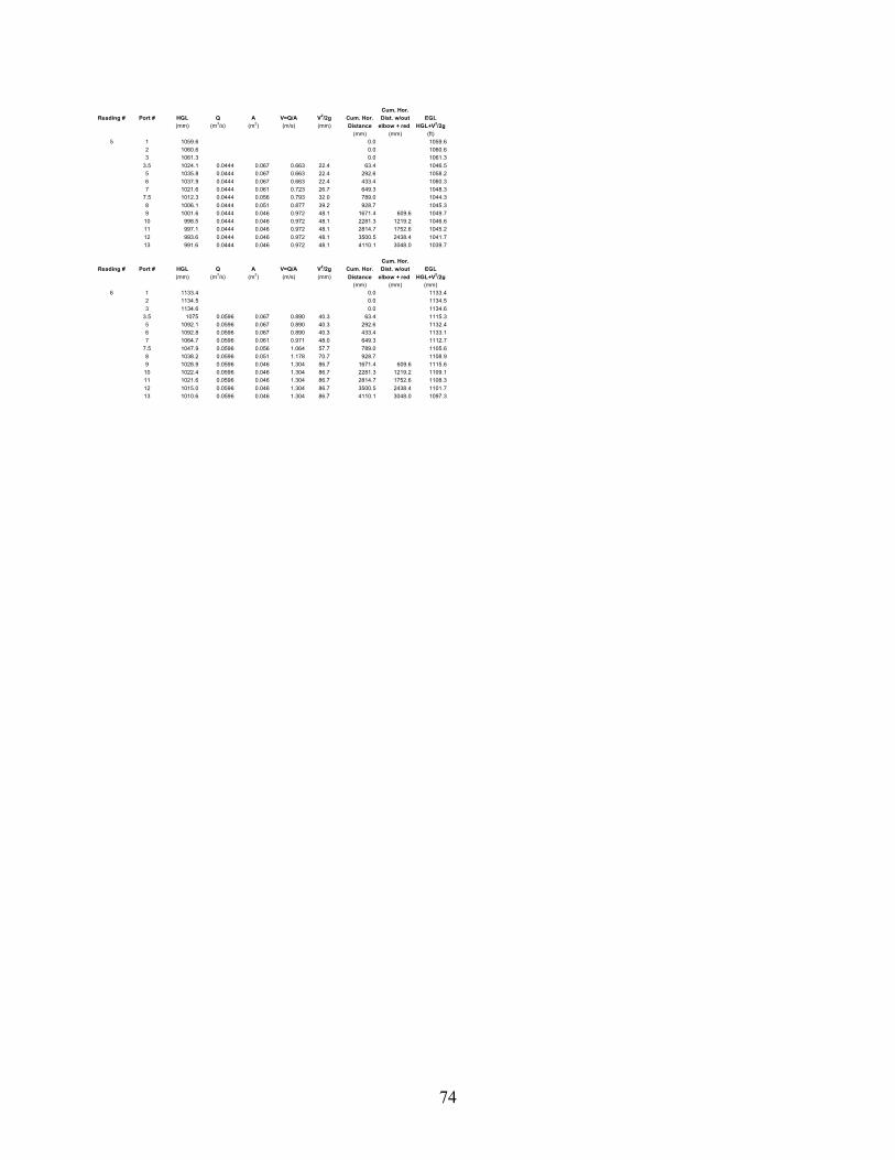
74
Cum. Hor.Reading # Port # HGL Q A V=Q/A V2/2g Cum. Hor. Dist. w/out EGL
(mm) (m3/s) (m2) (m/s) (mm) Distance elbow + red HGL+V2/2g (mm) (mm) (ft)
5 1 1059.6 0.0 1059.62 1060.6 0.0 1060.63 1061.3 0.0 1061.3
3.5 1024.1 0.0444 0.067 0.663 22.4 63.4 1046.55 1035.8 0.0444 0.067 0.663 22.4 292.6 1058.26 1037.9 0.0444 0.067 0.663 22.4 433.4 1060.37 1021.6 0.0444 0.061 0.723 26.7 649.3 1048.3
7.5 1012.3 0.0444 0.056 0.793 32.0 789.0 1044.38 1006.1 0.0444 0.051 0.877 39.2 928.7 1045.39 1001.6 0.0444 0.046 0.972 48.1 1671.4 609.6 1049.7
10 998.5 0.0444 0.046 0.972 48.1 2281.3 1219.2 1046.611 997.1 0.0444 0.046 0.972 48.1 2814.7 1752.6 1045.212 993.6 0.0444 0.046 0.972 48.1 3500.5 2438.4 1041.713 991.6 0.0444 0.046 0.972 48.1 4110.1 3048.0 1039.7
Cum. Hor.Reading # Port # HGL Q A V=Q/A V2/2g Cum. Hor. Dist. w/out EGL
(mm) (m3/s) (m2) (m/s) (mm) Distance elbow + red HGL+V2/2g (mm) (mm) (mm)
6 1 1133.4 0.0 1133.42 1134.5 0.0 1134.53 1134.6 0.0 1134.6
3.5 1075 0.0596 0.067 0.890 40.3 63.4 1115.35 1092.1 0.0596 0.067 0.890 40.3 292.6 1132.46 1092.8 0.0596 0.067 0.890 40.3 433.4 1133.17 1064.7 0.0596 0.061 0.971 48.0 649.3 1112.7
7.5 1047.9 0.0596 0.056 1.064 57.7 789.0 1105.68 1038.2 0.0596 0.051 1.178 70.7 928.7 1108.99 1028.9 0.0596 0.046 1.304 86.7 1671.4 609.6 1115.6
10 1022.4 0.0596 0.046 1.304 86.7 2281.3 1219.2 1109.111 1021.6 0.0596 0.046 1.304 86.7 2814.7 1752.6 1108.312 1015.0 0.0596 0.046 1.304 86.7 3500.5 2438.4 1101.713 1010.6 0.0596 0.046 1.304 86.7 4110.1 3048.0 1097.3

75
Date: 7/21/1997 Reading # Q Headbox Projected He Ke = Average AverageRun#: 26 (cms) EGL EGL (mm) 2g/V2*He He KeData Collected By: JKL 1* 0.013 1085.9 1083.0 2.97 0.77Inlet Description: # 12 2* 0.023 1110.9 1109.4 1.58 0.13 8.20 0.15
3 0.034 1148.7 1144.8 3.87 0.14Barrel Slope: 1.00% 4 0.044 1188.7 1181.5 7.14 0.15 Average AverageInlet Diameter: 11.5 inches 5 0.051 1221.0 1211.6 9.39 0.15 He (no f) Ke (no f)Barrel Length: 12 feet 6 0.058 1251.5 1239.1 12.40 0.15 6.44 0.12Barrel Area: 0.04573Culvert Barrel Dia: 241.3 mm = 9.5" Note = Readings with a " * " were not included in the averageReducer # : 5Reducer length : 14.8125 inches
Reading # Q He total Hf elbow Hf reducer He (no f) Ke (no f)=(cms) (mm) (mm) (mm) (mm) 2g/V2*He
3 0.034 3.87 0.44 0.48 2.95 0.114 0.044 7.14 0.70 0.76 5.68 0.125 0.051 9.39 1.01 1.10 7.28 0.116 0.058 12.40 1.21 1.32 9.87 0.12
Cum. Hor. Cum. Hor.Reading # Port # HGL Q A V=Q/A V2/2g Cum. Hor. Dist. w/out EGL Reading # Port # HGL Q A V=Q/A V2/2g Cum. Hor. Dist. w/out EGL
(mm) (m3/s) (m2) (m/s) (mm) Distance elbow + red HGL+V2/2g (mm) (m3/s) (m2) (m/s) (mm) Distance elbow + red HGL+V2/2g (mm) (mm) (ft) (mm) (mm) (ft)
1 1 1086.2 0.0 1086.2 4 1 1187.8 0.0 1187.82 1085.7 0.0 1085.7 2 1188.9 0.0 1188.93 1085.9 0.0 1085.9 3 1189.3 0.0 1189.3
3.5 1082.8 0.0126 0.067 0.188 1.8 63.4 1084.6 3.5 1155.4 0.0438 0.067 0.654 21.8 63.4 1177.24 1091.8 0.0126 0.067 0.188 1.8 149.4 1093.6 4 1150.2 0.0438 0.067 0.654 21.8 149.4 1172.05 1083.1 0.0126 0.067 0.188 1.8 292.6 1084.9 5 1164.8 0.0438 0.067 0.654 21.8 292.6 1186.66 1083.0 0.0126 0.067 0.188 1.8 433.4 1084.8 6 1165.6 0.0438 0.067 0.654 21.8 433.4 1187.47 1081.9 0.0126 0.061 0.207 2.2 623.9 1084.1 7 1150.9 0.0438 0.061 0.720 26.5 623.9 1177.48 1079.8 0.0126 0.051 0.246 3.1 782.7 1082.9 8 1137.1 0.0438 0.051 0.854 37.2 782.7 1174.39 1079.0 0.0126 0.046 0.276 3.9 1492.3 609.6 1082.9 9 1132.9 0.0438 0.046 0.958 46.8 1492.3 609.6 1179.7
10 1078.6 0.0126 0.046 0.276 3.9 2101.9 1219.2 1082.5 10 1129.7 0.0438 0.046 0.958 46.8 2101.9 1219.2 1176.511 1078.4 0.0126 0.046 0.276 3.9 2635.3 1752.6 1082.3 11 1128.7 0.0438 0.046 0.958 46.8 2635.3 1752.6 1175.512 1078.0 0.0126 0.046 0.276 3.9 3321.1 2438.4 1081.9 12 1125.6 0.0438 0.046 0.958 46.8 3321.1 2438.4 1172.413 1078.2 0.0126 0.046 0.276 3.9 3930.7 3048.0 1082.1 13 1124.0 0.0438 0.046 0.958 46.8 3930.7 3048.0 1170.8
Cum. Hor. Cum. Hor.Reading # Port # HGL Q A V=Q/A V2/2g Cum. Hor. Dist. w/out EGL Reading # Port # HGL Q A V=Q/A V2/2g Cum. Hor. Dist. w/out EGL
(mm) (m3/s) (m2) (m/s) (mm) Distance elbow + red HGL+V2/2g (mm) (m3/s) (m2) (m/s) (mm) Distance elbow + red HGL+V2/2g (mm) (mm) (ft) (mm) (mm) (ft)
2 1 1110.8 0.0 1110.8 5 1 1220.1 0.0 1220.12 1110.8 0.0 1110.8 2 1221.5 0.0 1221.53 1111.2 0.0 1111.2 3 1221.5 0.0 1221.5
3.5 1102.2 0.0225 0.067 0.336 5.7 63.4 1107.9 3.5 1173.8 0.0510 0.067 0.761 29.5 63.4 1203.34 1105.7 0.0225 0.067 0.336 5.7 149.4 1111.4 4 1172.7 0.0510 0.067 0.761 29.5 149.4 1202.25 1104.9 0.0225 0.067 0.336 5.7 292.6 1110.6 5 1189.1 0.0510 0.067 0.761 29.5 292.6 1218.66 1105.0 0.0225 0.067 0.336 5.7 433.4 1110.7 6 1189.1 0.0510 0.067 0.761 29.5 433.4 1218.67 1101.1 0.0225 0.061 0.370 7.0 623.9 1108.1 7 1168.8 0.0510 0.061 0.839 35.9 623.9 1204.78 1098.2 0.0225 0.051 0.439 9.8 782.7 1108.0 8 1152.3 0.0510 0.051 0.994 50.4 782.7 1202.79 1096.3 0.0225 0.046 0.492 12.4 1492.3 609.6 1108.7 9 1146.0 0.0510 0.046 1.116 63.5 1492.3 609.6 1209.5
10 1095.7 0.0225 0.046 0.492 12.4 2101.9 1219.2 1108.1 10 1140.6 0.0510 0.046 1.116 63.5 2101.9 1219.2 1204.111 1095.2 0.0225 0.046 0.492 12.4 2635.3 1752.6 1107.6 11 1138.8 0.0510 0.046 1.116 63.5 2635.3 1752.6 1202.312 1094.4 0.0225 0.046 0.492 12.4 3321.1 2438.4 1106.8 12 1135.6 0.0510 0.046 1.116 63.5 3321.1 2438.4 1199.113 1093.7 0.0225 0.046 0.492 12.4 3930.7 3048.0 1106.1 13 1132.6 0.0510 0.046 1.116 63.5 3930.7 3048.0 1196.1
Cum. Hor. Cum. Hor.Reading # Port # HGL Q A V=Q/A V2/2g Cum. Hor. Dist. w/out EGL Reading # Port # HGL Q A V=Q/A V2/2g Cum. Hor. Dist. w/out EGL
(mm) (m3/s) (m2) (m/s) (mm) Distance elbow + red HGL+V2/2g (mm) (m3/s) (m2) (m/s) (mm) Distance elbow + red HGL+V2/2g (mm) (mm) (ft) (mm) (mm) (mm)
3 1 1148.4 0.0 1148.4 6 1 1250.1 0.0 1250.12 1149 0.0 1149.0 2 1252.4 0.0 1252.43 1148.6 0.0 1148.6 3 1252 0.0 1252.0
3.5 1128.8 0.0337 0.067 0.503 12.9 63.4 1141.7 3.5 1194.9 0.0575 0.067 0.858 37.5 63.4 1232.44 1125.6 0.0337 0.067 0.503 12.9 149.4 1138.5 4 1207.3 0.0575 0.067 0.858 37.5 149.4 1244.85 1135.3 0.0337 0.067 0.503 12.9 292.6 1148.2 5 1212.1 0.0575 0.067 0.858 37.5 292.6 1249.66 1136.4 0.0337 0.067 0.503 12.9 433.4 1149.3 6 1211.8 0.0575 0.067 0.858 37.5 433.4 1249.37 1126.4 0.0337 0.061 0.554 15.7 623.9 1142.1 7 1185.3 0.0575 0.061 0.946 45.6 623.9 1230.98 1119.0 0.0337 0.051 0.657 22.0 782.7 1141.0 8 1165.9 0.0575 0.051 1.121 64.0 782.7 1229.99 1116.0 0.0337 0.046 0.737 27.7 1492.3 609.6 1143.7 9 1155.2 0.0575 0.046 1.258 80.7 1492.3 609.6 1235.9
10 1114.1 0.0337 0.046 0.737 27.7 2101.9 1219.2 1141.8 10 1149.5 0.0575 0.046 1.258 80.7 2101.9 1219.2 1230.211 1113.1 0.0337 0.046 0.737 27.7 2635.3 1752.6 1140.8 11 1148.3 0.0575 0.046 1.258 80.7 2635.3 1752.6 1229.012 1111.1 0.0337 0.046 0.737 27.7 3321.1 2438.4 1138.8 12 1142.9 0.0575 0.046 1.258 80.7 3321.1 2438.4 1223.613 1110.6 0.0337 0.046 0.737 27.7 3930.7 3048.0 1138.3 13 1139.5 0.0575 0.046 1.258 80.7 3930.7 3048.0 1220.2

76
Date: 12/31/1997 Reading # Q Headbox Projected He Ke = Average AverageRun#: Hw 2 (cms) EGL EGL (mm) 2g/V2*He He KeData Collected By: DAB 1* 0.0192 953.3 950.8 2.53 0.60Inlet Description: Headwall 2* 0.0327 973.9 971.6 2.26 0.19 44.56 0.56
3* 0.0382 994.9 986.3 8.65 0.52Barrel Slope: 3.50% 4 0.0464 1021.0 1008.1 12.91 0.53Inlet Diameter: 11.5 inches 5 0.0575 1053.3 1031.5 21.75 0.58Barrel Length: 12.9 feet 6 0.0680 1089.8 1059.5 30.29 0.58Barrel Area: 0.067 7 0.0764 1119.3 1082.6 36.66 0.55Culvert Barrel Dia: 11.5 in. = 292.1 mm 8 0.0861 1157.1 1111.2 45.94 0.55Reducer # : Na 9 0.0955 1201.1 1141.7 59.43 0.57Reducer length : Na 10 0.1038 1239.3 1170.6 68.69 0.56
11 0.1117 1281.4 1200.6 80.82 0.57
Note = Readings with a " * " were not included in the average
Reading # Port # HGL Q A V=Q/A V2/2g Cum. Hor. EGL Reading # Port # HGL Q A V=Q/A V2/2g Cum. Hor. EGL(mm) (m3/s) (m2) (m/s) (mm) Distance HGL+V2/2g (mm) (m3/s) (m2) (m/s) (mm) Distance HGL+V2/2g
(mm) (ft) (mm) (ft)1 1 953.6 0.0 953.6 8 1 1153.5 0.0 1153.5
2 953.2 0.0 953.2 2 1158.4 0.0 1158.43 953.2 0.0 953.2 3 1159.5 0.0 1159.58 946.5 0.0192 0.0670 0.2866 4.186 609.6 950.7 8 1028.3 0.0861 0.0670 1.2851 84.170 609.6 1112.59 946.0 0.0192 0.0670 0.2866 4.186 1219.2 950.2 9 1018.7 0.0861 0.0670 1.2851 84.170 1219.2 1102.910 945.9 0.0192 0.0670 0.2866 4.186 1828.8 950.1 10 1016.4 0.0861 0.0670 1.2851 84.170 1828.8 1100.611 945.8 0.0192 0.0670 0.2866 4.186 2438.4 950.0 11 1016.9 0.0861 0.0670 1.2851 84.170 2438.4 1101.112 945.3 0.0192 0.0670 0.2866 4.186 3048.0 949.5 12 1015.3 0.0861 0.0670 1.2851 84.170 3048.0 1099.513 945.3 0.0192 0.0670 0.2866 4.186 3657.6 949.5 13 1012.1 0.0861 0.0670 1.2851 84.170 3657.6 1096.3
Reading # Port # HGL Q A V=Q/A V2/2g Cum. Hor. EGL Reading # Port # HGL Q A V=Q/A V2/2g Cum. Hor. EGL(mm) (m3/s) (m2) (m/s) (mm) Distance HGL+V2/2g (mm) (m3/s) (m2) (m/s) (mm) Distance HGL+V2/2g
(mm) (ft) (mm) (ft)2 1 973.8 0.0 973.8 9 1 1198.0 0.0 1198.0
2 973.7 0.0 973.7 2 1203 0.0 1203.03 974.2 0.0 974.2 3 1202.4 0.0 1202.48 959.6 0.0327 0.0670 0.4881 12.141 609.6 971.7 8 1038.4 0.0955 0.0670 1.4254 103.552 609.6 1142.09 958.3 0.0327 0.0670 0.4881 12.141 1219.2 970.4 9 1029.6 0.0955 0.0670 1.4254 103.552 1219.2 1133.210 958.1 0.0327 0.0670 0.4881 12.141 1828.8 970.2 10 1028.7 0.0955 0.0670 1.4254 103.552 1828.8 1132.311 958.1 0.0327 0.0670 0.4881 12.141 2438.4 970.2 11 1027.2 0.0955 0.0670 1.4254 103.552 2438.4 1130.812 957.3 0.0327 0.0670 0.4881 12.141 3048.0 969.4 12 1024.5 0.0955 0.0670 1.4254 103.552 3048.0 1128.113 957.5 0.0327 0.0670 0.4881 12.141 3657.6 969.6 13 1022.4 0.0955 0.0670 1.4254 103.552 3657.6 1126.0
Reading # Port # HGL Q A V=Q/A V2/2g Cum. Hor. EGL Reading # Port # HGL Q A V=Q/A V2/2g Cum. Hor. EGL(mm) (m3/s) (m2) (m/s) (mm) Distance HGL+V2/2g (mm) (m3/s) (m2) (m/s) (mm) Distance HGL+V2/2g
(mm) (ft) (mm) (ft)3 1 994.5 0.0 994.5 10 1 1236.0 0.0 1236.0
2 995 0.0 995.0 2 1239.9 0.0 1239.93 995.3 0.0 995.3 3 1241.9 0.0 1241.98 970.1 0.0382 0.0670 0.5701 16.568 609.6 986.7 8 1049.1 0.1038 0.0670 1.5493 122.334 609.6 1171.49 968.6 0.0382 0.0670 0.5701 16.568 1219.2 985.2 9 1039.3 0.1038 0.0670 1.5493 122.334 1219.2 1161.610 968.6 0.0382 0.0670 0.5701 16.568 1828.8 985.2 10 1036.4 0.1038 0.0670 1.5493 122.334 1828.8 1158.711 969.1 0.0382 0.0670 0.5701 16.568 2438.4 985.7 11 1034.8 0.1038 0.0670 1.5493 122.334 2438.4 1157.112 968.7 0.0382 0.0670 0.5701 16.568 3048.0 985.3 12 1031.2 0.1038 0.0670 1.5493 122.334 3048.0 1153.513 968.3 0.0382 0.0670 0.5701 16.568 3657.6 984.9 13 1032.1 0.1038 0.0670 1.5493 122.334 3657.6 1154.4
Reading # Port # HGL Q A V=Q/A V2/2g Cum. Hor. EGL Reading # Port # HGL Q A V=Q/A V2/2g Cum. Hor. EGL(mm) (m3/s) (m2) (m/s) (mm) Distance HGL+V2/2g (mm) (m3/s) (m2) (m/s) (mm) Distance HGL+V2/2g
(mm) (ft) (mm) (ft)4 1 1020.9 0.0 1020.9 11 1 1279.9 0.0 1279.9
2 1021 0.0 1021.0 2 1281.7 0.0 1281.73 1021.1 0.0 1021.1 3 1282.7 0.0 1282.78 983 0.0464 0.0670 0.6925 24.445 609.6 1007.4 8 1058.2 0.1117 0.0670 1.6672 141.663 609.6 1199.99 981.5 0.0464 0.0670 0.6925 24.445 1219.2 1005.9 9 1050.0 0.1117 0.0670 1.6672 141.663 1219.2 1191.710 980.5 0.0464 0.0670 0.6925 24.445 1828.8 1004.9 10 1046.0 0.1117 0.0670 1.6672 141.663 1828.8 1187.711 979.4 0.0464 0.0670 0.6925 24.445 2438.4 1003.8 11 1046.6 0.1117 0.0670 1.6672 141.663 2438.4 1188.312 978.1 0.0464 0.0670 0.6925 24.445 3048.0 1002.5 12 1042.2 0.1117 0.0670 1.6672 141.663 3048.0 1183.913 978.2 0.0464 0.0670 0.6925 24.445 3657.6 1002.6 13 1038.8 0.1117 0.0670 1.6672 141.663 3657.6 1180.5
Reading # Port # HGL Q A V=Q/A V2/2g Cum. Hor. EGL(mm) (m3/s) (m2) (m/s) (mm) Distance HGL+V2/2g
(mm) (ft)5 1 1052.6 0.0 1052.6
2 1053.4 0.0 1053.43 1053.8 0.0 1053.88 994.3 0.0575 0.0670 0.8582 37.539 609.6 1031.89 990.6 0.0575 0.0670 0.8582 37.539 1219.2 1028.110 991.0 0.0575 0.0670 0.8582 37.539 1828.8 1028.511 989.9 0.0575 0.0670 0.8582 37.539 2438.4 1027.412 990.2 0.0575 0.0670 0.8582 37.539 3048.0 1027.713 988.2 0.0575 0.0670 0.8582 37.539 3657.6 1025.7

77
Reading # Port # HGL Q A V=Q/A V2/2g Cum. Hor. EGL(mm) (m3/s) (m2) (m/s) (mm) Distance HGL+V2/2g
(mm) (ft)6 1 1088.6 0.0 1088.6
2 1090 0.0 1090.03 1090.7 0.0 1090.78 1007.5 0.0680 0.0670 1.0149 52.501 609.6 1060.09 1002.3 0.0680 0.0670 1.0149 52.501 1219.2 1054.810 999.9 0.0680 0.0670 1.0149 52.501 1828.8 1052.411 1000.7 0.0680 0.0670 1.0149 52.501 2438.4 1053.212 998.6 0.0680 0.0670 1.0149 52.501 3048.0 1051.113 997.9 0.0680 0.0670 1.0149 52.501 3657.6 1050.4
Reading # Port # HGL Q A V=Q/A V2/2g Cum. Hor. EGL(mm) (m3/s) (m2) (m/s) (mm) Distance HGL+V2/2g
(mm) (ft)7 1 1117.9 0.0 1117.9
2 1119.4 0.0 1119.43 1120.5 0.0 1120.58 1016.7 0.0764 0.0670 1.1403 66.273 609.6 1083.09 1011.0 0.0764 0.0670 1.1403 66.273 1219.2 1077.310 1009.7 0.0764 0.0670 1.1403 66.273 1828.8 1076.011 1008.5 0.0764 0.0670 1.1403 66.273 2438.4 1074.812 1007.9 0.0764 0.0670 1.1403 66.273 3048.0 1074.213 1006.1 0.0764 0.0670 1.1403 66.273 3657.6 1072.4

78
Date: 12/22/1997 Reading # Q Headbox Projected He Ke = Average AverageRun#: Bm 8 (cms) EGL EGL (mm) 2g/V2*He He KeData Collected By: DAB 1* 0.020 961.3 960.0 1.29 0.28Inlet Description: # 13 2* 0.029 980.5 977.5 3.01 0.31 26.01 0.33
3* 0.037 997.4 992.7 4.68 0.30Barrel Slope: 5.00% 4 0.046 1019.2 1012.1 7.02 0.29Inlet Diameter: 11.5 inches 5 0.058 1048.1 1036.3 11.85 0.32Barrel Length: 12.9 feet 6 0.068 1082.9 1064.8 18.11 0.34Barrel Area: 0.067 7 0.077 1113.6 1091.0 22.55 0.34Culvert Barrel Dia: 11.5 in. = 292.1 mm 8 0.086 1151.8 1120.6 31.18 0.37Reducer # : Na 9 0.097 1191.2 1159.2 31.92 0.30Reducer length : Na 10 0.104 1227.9 1189.1 38.75 0.31
11 0.112 1261.4 1214.6 46.73 0.33
Note = Readings with a " * " were not included in the average
Reading # Port # HGL Q A V=Q/A V2/2g Cum. Hor. EGL Reading # Port # HGL Q A V=Q/A V2/2g Cum. Hor. EGL(mm) (m3/s) (m2) (m/s) (mm) Distance HGL+V2/2g (mm) (m3/s) (m2) (m/s) (mm) Distance HGL+V2/2g
(mm) (ft) (mm) (ft)1 1 961.4 0.0 961.4 7 1 1112.6 0.0 1112.6
2 961.3 0.0 961.3 2 1112.5 0.0 1112.53 961.2 0.0 961.2 3 1115.7 0.0 1115.78 955.0 0.0203 0.067 0.303 4.7 609.6 959.7 8 1025.6 0.0766 0.067 1.143 66.6 609.6 1092.29 954.9 0.0203 0.067 0.303 4.7 1219.2 959.6 9 1016.4 0.0766 0.067 1.143 66.6 1219.2 1083.0
10 954.7 0.0203 0.067 0.303 4.7 1828.8 959.4 10 1019.1 0.0766 0.067 1.143 66.6 1828.8 1085.711 953.7 0.0203 0.067 0.303 4.7 2438.4 958.4 11 1013.2 0.0766 0.067 1.143 66.6 2438.4 1079.812 953.9 0.0203 0.067 0.303 4.7 3048.0 958.6 12 1013.5 0.0766 0.067 1.143 66.6 3048.0 1080.113 953.8 0.0203 0.067 0.303 4.7 3657.6 958.5 13 1013.4 0.0766 0.067 1.143 66.6 3657.6 1080.0
Reading # Port # HGL Q A V=Q/A V2/2g Cum. Hor. EGL Reading # Port # HGL Q A V=Q/A V2/2g Cum. Hor. EGL(mm) (m3/s) (m2) (m/s) (mm) Distance HGL+V2/2g (mm) (m3/s) (m2) (m/s) (mm) Distance HGL+V2/2g
(mm) (ft) (mm) (ft)2 1 980.6 0.0 980.6 8 1 1150.1 0.0 1150.1
2 980.4 0.0 980.4 2 1151.7 0.0 1151.73 980.6 0.0 980.6 3 1153.5 0.0 1153.58 967.8 0.0294 0.067 0.439 9.8 609.6 977.6 8 1037.1 0.0864 0.067 1.290 84.8 609.6 1121.99 966.5 0.0294 0.067 0.439 9.8 1219.2 976.3 9 1028.7 0.0864 0.067 1.290 84.8 1219.2 1113.5
10 966.2 0.0294 0.067 0.439 9.8 1828.8 976.0 10 1027.9 0.0864 0.067 1.290 84.8 1828.8 1112.711 964.3 0.0294 0.067 0.439 9.8 2438.4 974.1 11 1023.4 0.0864 0.067 1.290 84.8 2438.4 1108.212 965.2 0.0294 0.067 0.439 9.8 3048.0 975.0 12 1024.2 0.0864 0.067 1.290 84.8 3048.0 1109.013 965.3 0.0294 0.067 0.439 9.8 3657.6 975.1 13 1024.2 0.0864 0.067 1.290 84.8 3657.6 1109.0
Reading # Port # HGL Q A V=Q/A V2/2g Cum. Hor. EGL Reading # Port # HGL Q A V=Q/A V2/2g Cum. Hor. EGL(mm) (m3/s) (m2) (m/s) (mm) Distance HGL+V2/2g (mm) (m3/s) (m2) (m/s) (mm) Distance HGL+V2/2g
(mm) (ft) (mm) (ft)3 1 997.7 0.0 997.7 9 1 1189.3 0.0 1189.3
2 997.2 0.0 997.2 2 1192.7 0.0 1192.73 997.3 0.0 997.3 3 1191.5 0.0 1191.58 977.0 0.0372 0.067 0.555 15.7 609.6 992.7 8 1053.4 0.0966 0.067 1.442 106.0 609.6 1159.49 975.2 0.0372 0.067 0.555 15.7 1219.2 990.9 9 1043.0 0.0966 0.067 1.442 106.0 1219.2 1149.0
10 975.0 0.0372 0.067 0.555 15.7 1828.8 990.7 10 1040.5 0.0966 0.067 1.442 106.0 1828.8 1146.511 973.5 0.0372 0.067 0.555 15.7 2438.4 989.2 11 1030.8 0.0966 0.067 1.442 106.0 2438.4 1136.812 974.4 0.0372 0.067 0.555 15.7 3048.0 990.1 12 1033.2 0.0966 0.067 1.442 106.0 3048.0 1139.213 973.2 0.0372 0.067 0.555 15.7 3657.6 988.9 13 1032.4 0.0966 0.067 1.442 106.0 3657.6 1138.4
Reading # Port # HGL Q A V=Q/A V2/2g Cum. Hor. EGL Reading # Port # HGL Q A V=Q/A V2/2g Cum. Hor. EGL(mm) (m3/s) (m2) (m/s) (mm) Distance HGL+V2/2g (mm) (m3/s) (m2) (m/s) (mm) Distance HGL+V2/2g
(mm) (ft) (mm) (ft)4 1 1018.6 0.0 1018.6 10 1 1224.2 0.0 1224.2
2 1019.9 0.0 1019.9 2 1230.1 0.0 1230.13 1019.0 0.0 1019.0 3 1229.4 0.0 1229.48 987.6 0.0462 0.067 0.690 24.2 609.6 1011.8 8 1068.1 0.1042 0.067 1.555 123.3 609.6 1191.49 985.1 0.0462 0.067 0.690 24.2 1219.2 1009.3 9 1051.5 0.1042 0.067 1.555 123.3 1219.2 1174.8
10 985.1 0.0462 0.067 0.690 24.2 1828.8 1009.3 10 1047.6 0.1042 0.067 1.555 123.3 1828.8 1170.911 982.7 0.0462 0.067 0.690 24.2 2438.4 1006.9 11 1037.8 0.1042 0.067 1.555 123.3 2438.4 1161.112 983.3 0.0462 0.067 0.690 24.2 3048.0 1007.5 12 1039.1 0.1042 0.067 1.555 123.3 3048.0 1162.413 981.9 0.0462 0.067 0.690 24.2 3657.6 1006.1 13 1040.7 0.1042 0.067 1.555 123.3 3657.6 1164.0
Reading # Port # HGL Q A V=Q/A V2/2g Cum. Hor. EGL Reading # Port # HGL Q A V=Q/A V2/2g Cum. Hor. EGL(mm) (m3/s) (m2) (m/s) (mm) Distance HGL+V2/2g (mm) (m3/s) (m2) (m/s) (mm) Distance HGL+V2/2g
(mm) (ft) (mm) (ft)5 1 1047.8 0.0 1047.8 11 1 1255.8 0.0 1255.8
2 1047.1 0.0 1047.1 2 1262.5 0.0 1262.53 1049.5 0.0 1049.5 3 1265.8 0.0 1265.88 999.0 0.0575 0.067 0.858 37.5 609.6 1036.5 8 1072.8 0.1118 0.067 1.669 141.9 609.6 1214.79 995.6 0.0575 0.067 0.858 37.5 1219.2 1033.1 9 1061.6 0.1118 0.067 1.669 141.9 1219.2 1203.5
10 995.1 0.0575 0.067 0.858 37.5 1828.8 1032.6 10 1054.5 0.1118 0.067 1.669 141.9 1828.8 1196.411 991.9 0.0575 0.067 0.858 37.5 2438.4 1029.4 11 1047.6 0.1118 0.067 1.669 141.9 2438.4 1189.512 993.4 0.0575 0.067 0.858 37.5 3048.0 1030.9 12 1050.0 0.1118 0.067 1.669 141.9 3048.0 1191.913 992.7 0.0575 0.067 0.858 37.5 3657.6 1030.2 13 1046.8 0.1118 0.067 1.669 141.9 3657.6 1188.7
Reading # Port # HGL Q A V=Q/A V2/2g Cum. Hor. EGL(mm) (m3/s) (m2) (m/s) (mm) Distance HGL+V2/2g
(mm) (ft)6 1 1082.6 0.0 1082.6
2 1083.8 0.0 1083.83 1082.4 0.0 1082.48 1013.6 0.0680 0.067 1.015 52.5 609.6 1066.19 1007.0 0.0680 0.067 1.015 52.5 1219.2 1059.5
10 1007.3 0.0680 0.067 1.015 52.5 1828.8 1059.811 1003.3 0.0680 0.067 1.015 52.5 2438.4 1055.812 1004.8 0.0680 0.067 1.015 52.5 3048.0 1057.313 1004.6 0.0680 0.067 1.015 52.5 3657.6 1057.1

79
Date: 12/29/1997 Reading # Q Headbox Projected He Ke = Average AverageRun#: Bm 7 (cms) EGL EGL (mm) 2g/V2*He He KeData Collected By: DAB 1* 0.020 953.4 951.9 1.50 0.34Inlet Description: # 13 2* 0.033 970.9 972.1 -1.20 -0.10 24.35 0.31
3* 0.037 990.3 986.2 4.10 0.27Barrel Slope: 3.50% 4 0.045 1011.9 1005.3 6.65 0.29Inlet Diameter: 11.5 inches 5 0.056 1041.9 1030.6 11.22 0.32Barrel Length: 12.9 feet 6 0.067 1076.3 1060.4 15.90 0.31Barrel Area: 0.067 7 0.076 1106.8 1085.3 21.54 0.33Culvert Barrel Dia: 11.5 in. = 292.1 mm 8 0.086 1143.3 1115.7 27.61 0.33Reducer # : Na 9 0.095 1182.7 1152.1 30.58 0.30Reducer length : Na 10 0.103 1217.1 1180.0 37.10 0.31
11 0.111 1251.9 1207.7 44.24 0.32
Note = Readings with a " * " were not included in the average
Reading # Port # HGL Q A V=Q/A V2/2g Cum. Hor. EGL Reading # Port # HGL Q A V=Q/A V2/2g Cum. Hor. EGL(mm) (m3/s) (m2) (m/s) (mm) Distance HGL+V2/2g (mm) (m3/s) (m2) (m/s) (mm) Distance HGL+V2/2g
(mm) (ft) (mm) (ft)1 1 953.3 0.0 953.3 8 1 1141.2 0.0 1141.2
2 953.3 0.0 953.3 2 1143.3 0.0 1143.33 953.5 0.0 953.5 3 1145.5 0.0 1145.58 947.8 0.0196 0.067 0.293 4.4 609.6 952.2 8 1033.5 0.0856 0.067 1.278 83.2 609.6 1116.79 946.7 0.0196 0.067 0.293 4.4 1219.2 951.1 9 1024.7 0.0856 0.067 1.278 83.2 1219.2 1107.910 946.1 0.0196 0.067 0.293 4.4 1828.8 950.5 10 1025.2 0.0856 0.067 1.278 83.2 1828.8 1108.411 946.1 0.0196 0.067 0.293 4.4 2438.4 950.5 11 1023.7 0.0856 0.067 1.278 83.2 2438.4 1106.912 945.9 0.0196 0.067 0.293 4.4 3048.0 950.3 12 1020.5 0.0856 0.067 1.278 83.2 3048.0 1103.713 946.2 0.0196 0.067 0.293 4.4 3657.6 950.6 13 1020.7 0.0856 0.067 1.278 83.2 3657.6 1103.9
Reading # Port # HGL Q A V=Q/A V2/2g Cum. Hor. EGL Reading # Port # HGL Q A V=Q/A V2/2g Cum. Hor. EGL(mm) (m3/s) (m2) (m/s) (mm) Distance HGL+V2/2g (mm) (m3/s) (m2) (m/s) (mm) Distance HGL+V2/2g
(mm) (ft) (mm) (ft)2 1 970.7 0.0 970.7 9 1 1180.6 0.0 1180.6
2 971.3 0.0 971.3 2 1183.1 0.0 1183.13 970.6 0.0 970.6 3 1184.3 0.0 1184.38 959.8 0.0328 0.067 0.490 12.2 609.6 972.0 8 1051.7 0.0950 0.067 1.418 102.5 609.6 1154.29 959.0 0.0328 0.067 0.490 12.2 1219.2 971.2 9 1037.5 0.0950 0.067 1.418 102.5 1219.2 1140.010 958.2 0.0328 0.067 0.490 12.2 1828.8 970.4 10 1033.7 0.0950 0.067 1.418 102.5 1828.8 1136.211 957.5 0.0328 0.067 0.490 12.2 2438.4 969.7 11 1031.7 0.0950 0.067 1.418 102.5 2438.4 1134.212 957.5 0.0328 0.067 0.490 12.2 3048.0 969.7 12 1029.4 0.0950 0.067 1.418 102.5 3048.0 1131.913 957.7 0.0328 0.067 0.490 12.2 3657.6 969.9 13 1028.6 0.0950 0.067 1.418 102.5 3657.6 1131.1
Reading # Port # HGL Q A V=Q/A V2/2g Cum. Hor. EGL Reading # Port # HGL Q A V=Q/A V2/2g Cum. Hor. EGL(mm) (m3/s) (m2) (m/s) (mm) Distance HGL+V2/2g (mm) (m3/s) (m2) (m/s) (mm) Distance HGL+V2/2g
(mm) (ft) (mm) (ft)3 1 990.0 0.0 990.0 10 1 1213.4 0.0 1213.4
2 991.0 0.0 991.0 2 1219.4 0.0 1219.43 990.0 0.0 990.0 3 1218.4 0.0 1218.48 971.1 0.0366 0.067 0.546 15.2 609.6 986.3 8 1061.3 0.1031 0.067 1.539 120.7 609.6 1182.09 969.4 0.0366 0.067 0.546 15.2 1219.2 984.6 9 1045.2 0.1031 0.067 1.539 120.7 1219.2 1165.910 969.1 0.0366 0.067 0.546 15.2 1828.8 984.3 10 1041.7 0.1031 0.067 1.539 120.7 1828.8 1162.411 967.7 0.0366 0.067 0.546 15.2 2438.4 982.9 11 1039.7 0.1031 0.067 1.539 120.7 2438.4 1160.412 967.8 0.0366 0.067 0.546 15.2 3048.0 983.0 12 1037.4 0.1031 0.067 1.539 120.7 3048.0 1158.113 968.0 0.0366 0.067 0.546 15.2 3657.6 983.2 13 1034.4 0.1031 0.067 1.539 120.7 3657.6 1155.1
Reading # Port # HGL Q A V=Q/A V2/2g Cum. Hor. EGL Reading # Port # HGL Q A V=Q/A V2/2g Cum. Hor. EGL(mm) (m3/s) (m2) (m/s) (mm) Distance HGL+V2/2g (mm) (m3/s) (m2) (m/s) (mm) Distance HGL+V2/2g
(mm) (ft) (mm) (ft)4 1 1011.6 0.0 1011.6 11 1 1247.9 0.0 1247.9
2 1012.3 0.0 1012.3 2 1253.7 0.0 1253.73 1011.9 0.0 1011.9 3 1254.1 0.0 1254.18 982.0 0.0450 0.067 0.672 23.0 609.6 1005.0 8 1068.0 0.1112 0.067 1.660 140.4 609.6 1208.49 980.1 0.0450 0.067 0.672 23.0 1219.2 1003.1 9 1053.6 0.1112 0.067 1.660 140.4 1219.2 1194.010 979.2 0.0450 0.067 0.672 23.0 1828.8 1002.2 10 1052.0 0.1112 0.067 1.660 140.4 1828.8 1192.411 978.5 0.0450 0.067 0.672 23.0 2438.4 1001.5 11 1046.3 0.1112 0.067 1.660 140.4 2438.4 1186.712 978.3 0.0450 0.067 0.672 23.0 3048.0 1001.3 12 1043.5 0.1112 0.067 1.660 140.4 3048.0 1183.913 977.0 0.0450 0.067 0.672 23.0 3657.6 1000.0 13 1042.7 0.1112 0.067 1.660 140.4 3657.6 1183.1
Reading # Port # HGL Q A V=Q/A V2/2g Cum. Hor. EGL(mm) (m3/s) (m2) (m/s) (mm) Distance HGL+V2/2g
(mm) (ft)5 1 1041.0 0.0 1041.0
2 1042.4 0.0 1042.43 1042.2 0.0 1042.28 996.0 0.0557 0.067 0.831 35.2 609.6 1031.29 991.7 0.0557 0.067 0.831 35.2 1219.2 1026.910 991.3 0.0557 0.067 0.831 35.2 1828.8 1026.511 990.8 0.0557 0.067 0.831 35.2 2438.4 1026.012 989.8 0.0557 0.067 0.831 35.2 3048.0 1025.013 989.4 0.0557 0.067 0.831 35.2 3657.6 1024.6

80
Reading # Port # HGL Q A V=Q/A V2/2g Cum. Hor. EGL(mm) (m3/s) (m2) (m/s) (mm) Distance HGL+V2/2g
(mm) (ft)6 1 1075.7 0.0 1075.7
2 1077.0 0.0 1077.03 1076.2 0.0 1076.28 1010.0 0.0669 0.067 0.999 50.8 609.6 1060.89 1004.8 0.0669 0.067 0.999 50.8 1219.2 1055.610 1003.9 0.0669 0.067 0.999 50.8 1828.8 1054.711 1003.1 0.0669 0.067 0.999 50.8 2438.4 1053.912 1000.5 0.0669 0.067 0.999 50.8 3048.0 1051.313 1001.5 0.0669 0.067 0.999 50.8 3657.6 1052.3
Reading # Port # HGL Q A V=Q/A V2/2g Cum. Hor. EGL(mm) (m3/s) (m2) (m/s) (mm) Distance HGL+V2/2g
(mm) (ft)7 1 1106.3 0.0 1106.3
2 1107.0 0.0 1107.03 1107.2 0.0 1107.28 1021.2 0.0760 0.067 1.134 65.6 609.6 1086.89 1012.6 0.0760 0.067 1.134 65.6 1219.2 1078.210 1012.3 0.0760 0.067 1.134 65.6 1828.8 1077.911 1013.0 0.0760 0.067 1.134 65.6 2438.4 1078.612 1011.1 0.0760 0.067 1.134 65.6 3048.0 1076.713 1008.9 0.0760 0.067 1.134 65.6 3657.6 1074.5

81
Date: 12/19/1997 Reading # Q Headbox Projected He Ke = Average AverageRun#: Bm 6 (cms) EGL EGL (mm) 2g/V2*He He KeData Collected By: DAB 1* 0.022 939.7 939.3 0.40 0.07Inlet Description: # 12 2* 0.031 958.4 955.1 3.28 0.30 28.53 0.36
3* 0.039 976.8 971.8 5.04 0.30Barrel Slope: 0.05 4 0.047 1000.5 991.6 8.94 0.35Inlet Diameter: 11.5 inches 5 0.055 1022.9 1010.9 12.04 0.35Barrel Length: 12.9 feet 6 0.062 1045.2 1029.9 15.33 0.35Barrel Area: 0.067 7 0.070 1072.6 1052.0 20.53 0.37Culvert Barrel Dia: 11.5 in. = 292.1 mm 8 0.078 1099.2 1073.9 25.29 0.37Reducer # : Na 9 0.084 1123.8 1095.7 28.07 0.35Reducer length : Na 10 0.092 1155.2 1120.1 35.09 0.37
11 0.097 1177.2 1139.3 37.96 0.3612 0.105 1211.9 1165.1 46.77 0.3813 0.113 1250.5 1195.2 55.27 0.38
Note = Readings with a " * " were not included in the average
Reading # Port # HGL Q A V=Q/A V2/2g Cum. Hor. EGL Reading # Port # HGL Q A V=Q/A V2/2g Cum. Hor. EGL(mm) (m3/s) (m2) (m/s) (mm) Distance HGL+V2/2g (mm) (m3/s) (m2) (m/s) (mm) Distance HGL+V2/2g
(mm) (ft) (mm) (ft)1 1 939.5 0.0 939.5 8 1 1098.2 0.0 1098.2
2 939.8 0.0 939.8 2 1099.0 0.0 1099.03 939.8 0.0 939.8 3 1100.4 0.0 1100.48 932.4 0.0221 0.067 0.330 5.5 609.6 937.9 8 1005.8 0.0778 0.067 1.161 68.7 609.6 1074.59 931.9 0.0221 0.067 0.330 5.5 1219.2 937.4 9 999.6 0.0778 0.067 1.161 68.7 1219.2 1068.3
10 931.9 0.0221 0.067 0.330 5.5 1828.8 937.4 10 999.1 0.0778 0.067 1.161 68.7 1828.8 1067.811 928.4 0.0221 0.067 0.330 5.5 2438.4 933.9 11 994.0 0.0778 0.067 1.161 68.7 2438.4 1062.712 928.5 0.0221 0.067 0.330 5.5 3048.0 934.0 12 996.9 0.0778 0.067 1.161 68.7 3048.0 1065.613 928.0 0.0221 0.067 0.330 5.5 3657.6 933.5 13 994.8 0.0778 0.067 1.161 68.7 3657.6 1063.5
Reading # Port # HGL Q A V=Q/A V2/2g Cum. Hor. EGL Reading # Port # HGL Q A V=Q/A V2/2g Cum. Hor. EGL(mm) (m3/s) (m2) (m/s) (mm) Distance HGL+V2/2g (mm) (m3/s) (m2) (m/s) (mm) Distance HGL+V2/2g
(mm) (ft) (mm) (ft)2 1 958.6 0.0 958.6 9 1 1122.7 0.0 1122.7
2 958.3 0.0 958.3 2 1124.2 0.0 1124.23 958.2 0.0 958.2 3 1124.4 0.0 1124.48 944.1 0.0312 0.067 0.466 11.1 609.6 955.2 8 1016.7 0.0841 0.067 1.255 80.3 609.6 1097.09 943.1 0.0312 0.067 0.466 11.1 1219.2 954.2 9 1007.4 0.0841 0.067 1.255 80.3 1219.2 1087.7
10 942.6 0.0312 0.067 0.466 11.1 1828.8 953.7 10 1006.4 0.0841 0.067 1.255 80.3 1828.8 1086.711 942.3 0.0312 0.067 0.466 11.1 2438.4 953.4 11 1000.7 0.0841 0.067 1.255 80.3 2438.4 1081.012 942.7 0.0312 0.067 0.466 11.1 3048.0 953.8 12 1003.1 0.0841 0.067 1.255 80.3 3048.0 1083.413 941.9 0.0312 0.067 0.466 11.1 3657.6 953.0 13 1001.6 0.0841 0.067 1.255 80.3 3657.6 1081.9
Reading # Port # HGL Q A V=Q/A V2/2g Cum. Hor. EGL Reading # Port # HGL Q A V=Q/A V2/2g Cum. Hor. EGL(mm) (m3/s) (m2) (m/s) (mm) Distance HGL+V2/2g (mm) (m3/s) (m2) (m/s) (mm) Distance HGL+V2/2g
(mm) (ft) (mm) (ft)3 1 976.5 0.0 976.5 10 1 1153.1 0.0 1153.1
2 977.1 0.0 977.1 2 1155.4 0.0 1155.43 976.8 0.0 976.8 3 1157.1 0.0 1157.18 955.2 0.0385 0.067 0.575 16.8 609.6 972.0 8 1027.5 0.0915 0.067 1.366 95.1 609.6 1122.69 953.2 0.0385 0.067 0.575 16.8 1219.2 970.0 9 1016.0 0.0915 0.067 1.366 95.1 1219.2 1111.1
10 953.0 0.0385 0.067 0.575 16.8 1828.8 969.8 10 1012.9 0.0915 0.067 1.366 95.1 1828.8 1108.011 951.8 0.0385 0.067 0.575 16.8 2438.4 968.6 11 1009.2 0.0915 0.067 1.366 95.1 2438.4 1104.312 952.4 0.0385 0.067 0.575 16.8 3048.0 969.2 12 1011.5 0.0915 0.067 1.366 95.1 3048.0 1106.613 951.9 0.0385 0.067 0.575 16.8 3657.6 968.7 13 1009.8 0.0915 0.067 1.366 95.1 3657.6 1104.9
Reading # Port # HGL Q A V=Q/A V2/2g Cum. Hor. EGL Reading # Port # HGL Q A V=Q/A V2/2g Cum. Hor. EGL(mm) (m3/s) (m2) (m/s) (mm) Distance HGL+V2/2g (mm) (m3/s) (m2) (m/s) (mm) Distance HGL+V2/2g
(mm) (ft) (mm) (ft)4 1 999.7 0.0 999.7 11 1 1175.0 0.0 1175.0
2 1000.9 0.0 1000.9 2 1178.0 0.0 1178.03 1001.0 0.0 1001.0 3 1178.7 0.0 1178.78 966.5 0.0474 0.067 0.707 25.5 609.6 992.0 8 1034.6 0.0968 0.067 1.445 106.4 609.6 1141.09 963.9 0.0474 0.067 0.707 25.5 1219.2 989.4 9 1021.3 0.0968 0.067 1.445 106.4 1219.2 1127.7
10 964.2 0.0474 0.067 0.707 25.5 1828.8 989.7 10 1019.3 0.0968 0.067 1.445 106.4 1828.8 1125.711 962.3 0.0474 0.067 0.707 25.5 2438.4 987.8 11 1014.3 0.0968 0.067 1.445 106.4 2438.4 1120.712 963.1 0.0474 0.067 0.707 25.5 3048.0 988.6 12 1013.9 0.0968 0.067 1.445 106.4 3048.0 1120.313 962.8 0.0474 0.067 0.707 25.5 3657.6 988.3 13 1013.1 0.0968 0.067 1.445 106.4 3657.6 1119.5
Reading # Port # HGL Q A V=Q/A V2/2g Cum. Hor. EGL Reading # Port # HGL Q A V=Q/A V2/2g Cum. Hor. EGL(mm) (m3/s) (m2) (m/s) (mm) Distance HGL+V2/2g (mm) (m3/s) (m2) (m/s) (mm) Distance HGL+V2/2g
(mm) (ft) (mm) (ft)5 1 1022.4 0.0 1022.4 12 1 1208.8 0.0 1208.8
2 1022.9 0.0 1022.9 2 1212.9 0.0 1212.93 1023.4 0.0 1023.4 3 1214.0 0.0 1214.08 976.6 0.0551 0.067 0.822 34.5 609.6 1011.1 8 1042.5 0.1046 0.067 1.561 124.2 609.6 1166.79 973.3 0.0551 0.067 0.822 34.5 1219.2 1007.8 9 1030.3 0.1046 0.067 1.561 124.2 1219.2 1154.5
10 973.6 0.0551 0.067 0.822 34.5 1828.8 1008.1 10 1024.9 0.1046 0.067 1.561 124.2 1828.8 1149.111 971.4 0.0551 0.067 0.822 34.5 2438.4 1005.9 11 1017.2 0.1046 0.067 1.561 124.2 2438.4 1141.412 971.5 0.0551 0.067 0.822 34.5 3048.0 1006.0 12 1021.2 0.1046 0.067 1.561 124.2 3048.0 1145.413 971.2 0.0551 0.067 0.822 34.5 3657.6 1005.7 13 1019.6 0.1046 0.067 1.561 124.2 3657.6 1143.8
Reading # Port # HGL Q A V=Q/A V2/2g Cum. Hor. EGL Reading # Port # HGL Q A V=Q/A V2/2g Cum. Hor. EGL(mm) (m3/s) (m2) (m/s) (mm) Distance HGL+V2/2g (mm) (m3/s) (m2) (m/s) (mm) Distance HGL+V2/2g
(mm) (ft) (mm) (ft)6 1 1045.2 0.0 1045.2 13 1 1245.3 0.0 1245.3
2 1045.4 0.0 1045.4 2 1252.5 0.0 1252.53 1045.1 0.0 1045.1 3 1253.7 0.0 1253.78 986.6 0.0624 0.067 0.931 44.2 609.6 1030.8 8 1053.1 0.1127 0.067 1.682 144.2 609.6 1197.39 981.7 0.0624 0.067 0.931 44.2 1219.2 1025.9 9 1038.9 0.1127 0.067 1.682 144.2 1219.2 1183.1
10 981.9 0.0624 0.067 0.931 44.2 1828.8 1026.1 10 1034.7 0.1127 0.067 1.682 144.2 1828.8 1178.911 979.2 0.0624 0.067 0.931 44.2 2438.4 1023.4 11 1025.8 0.1127 0.067 1.682 144.2 2438.4 1170.012 980.4 0.0624 0.067 0.931 44.2 3048.0 1024.6 12 1030.3 0.1127 0.067 1.682 144.2 3048.0 1174.513 979.7 0.0624 0.067 0.931 44.2 3657.6 1023.9 13 1028.4 0.1127 0.067 1.682 144.2 3657.6 1172.6

82
Reading # Port # HGL Q A V=Q/A V2/2g Cum. Hor. EGL(mm) (m3/s) (m2) (m/s) (mm) Distance HGL+V2/2g
(mm) (ft)7 1 1071.0 0.0 1071.0
2 1072.5 0.0 1072.53 1074.2 0.0 1074.28 997.5 0.0702 0.067 1.048 56.0 609.6 1053.59 990.6 0.0702 0.067 1.048 56.0 1219.2 1046.6
10 991.0 0.0702 0.067 1.048 56.0 1828.8 1047.011 986.6 0.0702 0.067 1.048 56.0 2438.4 1042.612 989.0 0.0702 0.067 1.048 56.0 3048.0 1045.013 988.1 0.0702 0.067 1.048 56.0 3657.6 1044.1

83
Date: 12/18/1997 Reading # Q Headbox Projected He Ke = Average AverageRun#: Bm 5 (cms) EGL EGL (mm) 2g/V2*He He KeData Collected By: DAB 1* 0.019 935.2 933.3 1.87 0.45Inlet Description: # 12 2* 0.029 957.5 954.9 2.58 0.27 29.98 0.38
3* 0.037 976.5 972.8 3.72 0.24Barrel Slope: 0.035 4 0.045 999.1 991.5 7.58 0.33Inlet Diameter: 11.5 inches 5 0.056 1031.5 1018.9 12.62 0.36Barrel Length: 12.9 feet 6 0.067 1066.0 1047.2 18.79 0.37Barrel Area: 0.067 7 0.076 1100.2 1075.4 24.75 0.37Culvert Barrel Dia: 11.5 in. = 292.1 mm 8 0.085 1137.6 1105.1 32.47 0.39Reducer # : Na 9 0.095 1179.1 1137.9 41.20 0.40Reducer length : Na 10 0.104 1214.9 1169.6 45.36 0.37
11 0.111 1253.6 1196.6 57.07 0.41
Note = Readings with a " * " were not included in the average
Reading # Port # HGL Q A V=Q/A V2/2g Cum. Hor. EGL Reading # Port # HGL Q A V=Q/A V2/2g Cum. Hor. EGL(mm) (m3/s) (m2) (m/s) (mm) Distance HGL+V2/2g (mm) (m3/s) (m2) (m/s) (mm) Distance HGL+V2/2g
(mm) (ft) (mm) (ft)1 1 936.2 0.0 936.2 8 1 1134.9 0.0 1134.9
2 934.9 0.0 934.9 2 1137.9 0.0 1137.93 934.5 0.0 934.5 3 1139.9 0.0 1139.98 929.1 0.0192 0.067 0.287 4.2 609.6 933.3 8 1023.1 0.0852 0.067 1.272 82.4 609.6 1105.59 928.8 0.0192 0.067 0.287 4.2 1219.2 933.0 9 1014.9 0.0852 0.067 1.272 82.4 1219.2 1097.3
10 928.2 0.0192 0.067 0.287 4.2 1828.8 932.4 10 1016.4 0.0852 0.067 1.272 82.4 1828.8 1098.811 926.1 0.0192 0.067 0.287 4.2 2438.4 930.3 11 1007.7 0.0852 0.067 1.272 82.4 2438.4 1090.112 927.7 0.0192 0.067 0.287 4.2 3048.0 931.9 12 1009.2 0.0852 0.067 1.272 82.4 3048.0 1091.613 927.8 0.0192 0.067 0.287 4.2 3657.6 932.0 13 1010.0 0.0852 0.067 1.272 82.4 3657.6 1092.4
Reading # Port # HGL Q A V=Q/A V2/2g Cum. Hor. EGL Reading # Port # HGL Q A V=Q/A V2/2g Cum. Hor. EGL(mm) (m3/s) (m2) (m/s) (mm) Distance HGL+V2/2g (mm) (m3/s) (m2) (m/s) (mm) Distance HGL+V2/2g
(mm) (ft) (mm) (ft)2 1 957.3 0.0 957.3 9 1 1177.5 0.0 1177.5
2 957.3 0.0 957.3 2 1180.3 0.0 1180.33 957.9 0.0 957.9 3 1179.5 0.0 1179.58 945.1 0.0291 0.067 0.434 9.6 609.6 954.7 8 1037.6 0.0950 0.067 1.418 102.5 609.6 1140.19 944.8 0.0291 0.067 0.434 9.6 1219.2 954.4 9 1026.5 0.0950 0.067 1.418 102.5 1219.2 1129.0
10 944.3 0.0291 0.067 0.434 9.6 1828.8 953.9 10 1026.4 0.0950 0.067 1.418 102.5 1828.8 1128.911 943.7 0.0291 0.067 0.434 9.6 2438.4 953.3 11 1021.0 0.0950 0.067 1.418 102.5 2438.4 1123.512 943.7 0.0291 0.067 0.434 9.6 3048.0 953.3 12 1023.1 0.0950 0.067 1.418 102.5 3048.0 1125.613 943.7 0.0291 0.067 0.434 9.6 3657.6 953.3 13 1022.1 0.0950 0.067 1.418 102.5 3657.6 1124.6
Reading # Port # HGL Q A V=Q/A V2/2g Cum. Hor. EGL Reading # Port # HGL Q A V=Q/A V2/2g Cum. Hor. EGL(mm) (m3/s) (m2) (m/s) (mm) Distance HGL+V2/2g (mm) (m3/s) (m2) (m/s) (mm) Distance HGL+V2/2g
(mm) (ft) (mm) (ft)3 1 976.6 0.0 976.6 10 1 1211.4 0.0 1211.4
2 976.4 0.0 976.4 2 1216.8 0.0 1216.83 976.5 0.0 976.5 3 1216.6 0.0 1216.68 957.1 0.0370 0.067 0.552 15.5 609.6 972.6 8 1049.1 0.1039 0.0670 1.5507 122.570 609.6 1171.79 956.1 0.0370 0.067 0.552 15.5 1219.2 971.6 9 1035.9 0.1039 0.0670 1.5507 122.570 1219.2 1158.5
10 955.7 0.0370 0.067 0.552 15.5 1828.8 971.2 10 1034.1 0.1039 0.0670 1.5507 122.570 1828.8 1156.711 953.6 0.0370 0.067 0.552 15.5 2438.4 969.1 11 1026.7 0.1039 0.0670 1.5507 122.570 2438.4 1149.312 954.3 0.0370 0.067 0.552 15.5 3048.0 969.8 12 1028.7 0.1039 0.0670 1.5507 122.570 3048.0 1151.313 954.6 0.0370 0.067 0.552 15.5 3657.6 970.1 13 1028.6 0.1039 0.0670 1.5507 122.570 3657.6 1151.2
Reading # Port # HGL Q A V=Q/A V2/2g Cum. Hor. EGL Reading # Port # HGL Q A V=Q/A V2/2g Cum. Hor. EGL(mm) (m3/s) (m2) (m/s) (mm) Distance HGL+V2/2g (mm) (m3/s) (m2) (m/s) (mm) Distance HGL+V2/2g
(mm) (ft) (mm) (ft)4 1 998.3 0.0 998.3 11 1 1249.6 0.0 1249.6
2 999.6 0.0 999.6 2 1255 0.0 1255.03 999.3 0.0 999.3 3 1256.3 0.0 1256.38 968.7 0.0452 0.067 0.675 23.2 609.6 991.9 8 1057.8 0.1114 0.0670 1.6627 140.903 609.6 1198.79 966.3 0.0452 0.067 0.675 23.2 1219.2 989.5 9 1046.4 0.1114 0.0670 1.6627 140.903 1219.2 1187.3
10 966.5 0.0452 0.067 0.675 23.2 1828.8 989.7 10 1038.5 0.1114 0.0670 1.6627 140.903 1828.8 1179.411 964.6 0.0452 0.067 0.675 23.2 2438.4 987.8 11 1033.2 0.1114 0.0670 1.6627 140.903 2438.4 1174.112 965.4 0.0452 0.067 0.675 23.2 3048.0 988.6 12 1038.3 0.1114 0.0670 1.6627 140.903 3048.0 1179.213 965.3 0.0452 0.067 0.675 23.2 3657.6 988.5 13 1035.7 0.1114 0.0670 1.6627 140.903 3657.6 1176.6
Reading # Port # HGL Q A V=Q/A V2/2g Cum. Hor. EGL(mm) (m3/s) (m2) (m/s) (mm) Distance HGL+V2/2g
(mm) (ft)5 1 1030.8 0.0 1030.8
2 1031.6 0.0 1031.63 1032.2 0.0 1032.28 984.0 0.0558 0.067 0.833 35.4 609.6 1019.49 980.5 0.0558 0.067 0.833 35.4 1219.2 1015.9
10 979.9 0.0558 0.067 0.833 35.4 1828.8 1015.311 977.9 0.0558 0.067 0.833 35.4 2438.4 1013.312 978.8 0.0558 0.067 0.833 35.4 3048.0 1014.213 978.0 0.0558 0.067 0.833 35.4 3657.6 1013.4

84
Reading # Port # HGL Q A V=Q/A V2/2g Cum. Hor. EGL(mm) (m3/s) (m2) (m/s) (mm) Distance HGL+V2/2g
(mm) (ft)6 1 1065.2 0.0 1065.2
2 1066.2 0.0 1066.23 1066.7 0.0 1066.78 998.0 0.0665 0.067 0.993 50.2 609.6 1048.29 992.4 0.0665 0.067 0.993 50.2 1219.2 1042.6
10 993.8 0.0665 0.067 0.993 50.2 1828.8 1044.011 990.0 0.0665 0.067 0.993 50.2 2438.4 1040.212 992.0 0.0665 0.067 0.993 50.2 3048.0 1042.213 990.5 0.0665 0.067 0.993 50.2 3657.6 1040.7
Reading # Port # HGL Q A V=Q/A V2/2g Cum. Hor. EGL(mm) (m3/s) (m2) (m/s) (mm) Distance HGL+V2/2g
(mm) (ft)7 1 1099.5 0.0 1099.5
2 1101.4 0.0 1101.43 1099.6 0.0 1099.68 1009.9 0.0764 0.067 1.140 66.3 609.6 1076.29 1004.5 0.0764 0.067 1.140 66.3 1219.2 1070.8
10 1003.6 0.0764 0.067 1.140 66.3 1828.8 1069.911 999.6 0.0764 0.067 1.140 66.3 2438.4 1065.912 1002.9 0.0764 0.067 1.140 66.3 3048.0 1069.213 1000.3 0.0764 0.067 1.140 66.3 3657.6 1066.6

85
Date: 7/21/1997 Reading # Q Headbox Projected He Ke = Average AverageRun#: 35 (cms) EGL EGL (mm) 2g/V2*He He KeData Collected By: ERU/JKL 1* 0.020 1036.6 1034.9 1.77 0.18Inlet Description: # 12 2* 0.033 1061.2 1067.6 -6.32 -0.24 6.12 0.10
3 0.038 1094.2 1090.7 3.52 0.10Barrel Slope: 0.50% 4 0.046 1125.4 1121.8 3.60 0.07Inlet Diameter: 11.5 inches 5 0.055 1166.5 1158.6 7.96 0.11Barrel Length: 12 feet 6 0.062 1197.9 1188.5 9.42 0.10Barrel Area: 0.04573Culvert Barrel Dia: 241.3 mm = 9.5" Note = Readings with a " * " were not included in the averageReducer # : 5Reducer length : 14.8125 inches
Cum. Hor. Cum. Hor.Reading # Port # HGL Q A V=Q/A V2/2g Cum. Hor. Dist. w/out EGL Reading # Port # HGL Q A V=Q/A V2/2g Cum. Hor. Dist. w/out EGL
(mm) (m3/s) (m2) (m/s) (mm) Distance elbow + red HGL+V2/2g (mm) (m3/s) (m2) (m/s) (mm) Distance elbow + red HGL+V2/2g (mm) (mm) (ft) (mm) (mm) (ft)
1 1 1036.5 0.0 1036.5 4 1 1124.7 0.0 1124.72 1036.9 0.0 1036.9 2 1126.2 0.0 1126.23 1036.5 0.0 1036.5 3 1125.4 0.0 1125.4
3.5 1029.6 0.0202 0.067 0.301 4.6 63.4 1034.2 3.5 1090.6 0.0459 0.067 0.685 23.9 63.4 1114.54 1029.8 0.0202 0.067 0.301 4.6 149.4 1034.4 4 1090.0 0.0459 0.067 0.685 23.9 149.4 1113.95 1031.1 0.0202 0.067 0.301 4.6 292.6 1035.7 5 1100.9 0.0459 0.067 0.685 23.9 292.6 1124.86 1031.6 0.0202 0.067 0.301 4.6 433.4 1036.2 6 1101.4 0.0459 0.067 0.685 23.9 433.4 1125.37 1029.3 0.0202 0.061 0.332 5.6 623.9 1034.9 7 1087.5 0.0459 0.061 0.755 29.0 623.9 1116.58 1026.6 0.0202 0.051 0.394 7.9 782.7 1034.5 8 1075.2 0.0459 0.051 0.895 40.8 782.7 1116.09 1024.4 0.0202 0.046 0.442 10.0 1492.3 609.6 1034.4 9 1068.7 0.0459 0.046 1.004 51.4 1492.3 609.6 1120.1
10 1023.8 0.0202 0.046 0.442 10.0 2101.9 1219.2 1033.8 10 1065.0 0.0459 0.046 1.004 51.4 2101.9 1219.2 1116.411 1023.3 0.0202 0.046 0.442 10.0 2635.3 1752.6 1033.3 11 1063.2 0.0459 0.046 1.004 51.4 2635.3 1752.6 1114.612 1022.4 0.0202 0.046 0.442 10.0 3321.1 2438.4 1032.4 12 1060.1 0.0459 0.046 1.004 51.4 3321.1 2438.4 1111.513 1022.3 0.0202 0.046 0.442 10.0 3930.7 3048.0 1032.3 13 1059.0 0.0459 0.046 1.004 51.4 3930.7 3048.0 1110.4
Cum. Hor. Cum. Hor.Reading # Port # HGL Q A V=Q/A V2/2g Cum. Hor. Dist. w/out EGL Reading # Port # HGL Q A V=Q/A V2/2g Cum. Hor. Dist. w/out EGL
(mm) (m3/s) (m2) (m/s) (mm) Distance elbow + red HGL+V2/2g (mm) (m3/s) (m2) (m/s) (mm) Distance elbow + red HGL+V2/2g (mm) (mm) (ft) (mm) (mm) (ft)
2 1 1061.1 0.0 1061.1 5 1 1165.3 0.0 1165.32 1061.1 0.0 1061.1 2 1166.8 0.0 1166.83 1061.5 0.0 1061.5 3 1167.5 0.0 1167.5
3.5 1049.0 0.0329 0.067 0.491 12.3 63.4 1061.3 3.5 1117.4 0.0545 0.067 0.813 33.7 63.4 1151.14 1049.2 0.0329 0.067 0.491 12.3 149.4 1061.5 4 1118.8 0.0545 0.067 0.813 33.7 149.4 1152.55 1052.3 0.0329 0.067 0.491 12.3 292.6 1064.6 5 1130.4 0.0545 0.067 0.813 33.7 292.6 1164.16 1052.7 0.0329 0.067 0.491 12.3 433.4 1065.0 6 1131.3 0.0545 0.067 0.813 33.7 433.4 1165.07 1047.9 0.0329 0.061 0.541 14.9 623.9 1062.8 7 1109.2 0.0545 0.061 0.896 41.0 623.9 1150.28 1042.4 0.0329 0.051 0.641 21.0 782.7 1063.4 8 1091.3 0.0545 0.051 1.062 57.5 782.7 1148.89 1040.4 0.0329 0.046 0.720 26.4 1492.3 609.6 1066.8 9 1083.1 0.0545 0.046 1.193 72.5 1492.3 609.6 1155.6
10 1038.9 0.0329 0.046 0.720 26.4 2101.9 1219.2 1065.3 10 1077.1 0.0545 0.046 1.193 72.5 2101.9 1219.2 1149.611 1038.3 0.0329 0.046 0.720 26.4 2635.3 1752.6 1064.7 11 1075.7 0.0545 0.046 1.193 72.5 2635.3 1752.6 1148.212 1037.1 0.0329 0.046 0.720 26.4 3321.1 2438.4 1063.5 12 1070.5 0.0545 0.046 1.193 72.5 3321.1 2438.4 1143.013 1036.4 0.0329 0.046 0.720 26.4 3930.7 3048.0 1062.8 13 1067.4 0.0545 0.046 1.193 72.5 3930.7 3048.0 1139.9
Cum. Hor. Cum. Hor.Reading # Port # HGL Q A V=Q/A V2/2g Cum. Hor. Dist. w/out EGL Reading # Port # HGL Q A V=Q/A V2/2g Cum. Hor. Dist. w/out EGL
(mm) (m3/s) (m2) (m/s) (mm) Distance elbow + red HGL+V2/2g (mm) (m3/s) (m2) (m/s) (mm) Distance elbow + red HGL+V2/2g (mm) (mm) (ft) (mm) (mm) (mm)
3 1 1093.8 0.0 1093.8 6 1 1195.3 0.0 1195.32 1094.1 0.0 1094.1 2 1199.4 0.0 1199.43 1094.8 0.0 1094.8 3 1199.1 0.0 1199.1
3.5 1072.4 0.0377 0.067 0.563 16.1 63.4 1088.5 3.5 1131 0.0621 0.067 0.927 43.8 63.4 1174.84 1072.0 0.0377 0.067 0.563 16.1 149.4 1088.1 4 1128.0 0.0621 0.067 0.927 43.8 149.4 1171.85 1078.9 0.0377 0.067 0.563 16.1 292.6 1095.0 5 1149.6 0.0621 0.067 0.927 43.8 292.6 1193.46 1079.4 0.0377 0.067 0.563 16.1 433.4 1095.5 6 1150.4 0.0621 0.067 0.927 43.8 433.4 1194.27 1069.0 0.0377 0.061 0.620 19.6 623.9 1088.6 7 1123.7 0.0621 0.061 1.021 53.2 623.9 1176.98 1059.7 0.0377 0.051 0.735 27.5 782.7 1087.2 8 1101.1 0.0621 0.051 1.211 74.7 782.7 1175.89 1055.2 0.0377 0.046 0.825 34.7 1492.3 609.6 1089.9 9 1090.0 0.0621 0.046 1.359 94.1 1492.3 609.6 1184.1
10 1052.7 0.0377 0.046 0.825 34.7 2101.9 1219.2 1087.4 10 1085.6 0.0621 0.046 1.359 94.1 2101.9 1219.2 1179.711 1052.6 0.0377 0.046 0.825 34.7 2635.3 1752.6 1087.3 11 1083.1 0.0621 0.046 1.359 94.1 2635.3 1752.6 1177.212 1052.5 0.0377 0.046 0.825 34.7 3321.1 2438.4 1087.2 12 1075.2 0.0621 0.046 1.359 94.1 3321.1 2438.4 1169.313 1049.3 0.0377 0.046 0.825 34.7 3930.7 3048.0 1084.0 13 1073.6 0.0621 0.046 1.359 94.1 3930.7 3048.0 1167.7

86
Date: 11/5/1997 Reading # Q Headbox Projected He Ke = Average AverageRun#: 34 (cms) EGL EGL (mm) 2g/V2*He He KeData Collected By: CRW 1* 0.008 919.7 918.9 0.79 0.57Inlet Description: # 13 2* 0.019 944.4 943.4 0.99 0.14 22.31 0.25
3* 0.031 971.2 970.9 0.32 0.02Barrel Slope: 0.02 4 0.037 998.2 991.4 6.87 0.26 Average AverageInlet Diameter: 11.5 inches 5 0.045 1026.4 1016.6 9.77 0.25 He (no f) KeBarrel Length: 12 feet 6 0.055 1067.9 1052.3 15.54 0.26Barrel Area: 0.0507 7 0.066 1113.2 1091.6 21.55 0.25 20.19 0.23Culvert Barrel Dia: 254 mm = 10.0 in. 8 0.075 1159.2 1132.3 26.91 0.24Reducer # : 11 9 0.085 1212.9 1180.0 32.95 0.23Reducer length : 11.5 inches 10 0.094 1268.7 1226.1 42.57 0.24
11* 0.103 1316.8 1272.9 43.87 0.21
Note = Readings with a " * " were not included in the average
Reading # Q He total Hf elbow Hf reducer He (no f) Ke (no f)=(cms) (mm) (mm) (mm) (mm) 2g/V2*He
4 0.037 6.87 0.29 0.22 6.36 0.245 0.045 9.77 0.48 0.37 8.92 0.236 0.055 15.54 0.73 0.57 14.23 0.247 0.066 21.55 1.08 0.84 19.63 0.238 0.075 26.91 1.54 1.20 24.17 0.229 0.085 32.95 2.04 1.58 29.32 0.21
10 0.094 42.57 2.18 1.69 38.70 0.22
Cum. Hor. Cum. Hor.Reading # Port # HGL Q A V=Q/A V2/2g Cum. Hor. Dist. w/out EGL Reading # Port # HGL Q A V=Q/A V2/2g Cum. Hor. Dist. w/out EGL
(mm) (m3/s) (m2) (m/s) (mm) Distance elbow + red HGL+V2/2g (mm) (m3/s) (m2) (m/s) (mm) Distance elbow + red HGL+V2/2g (mm) (mm) (ft) (mm) (mm) (mm)
1 1 919.6 0.0 919.6 7 1 1111.3 0.0 1111.32 919.7 0.0 919.7 2 1114.2 0.0 1114.23 919.9 0.0 919.9 3 1114.1 0.0 1114.1
3.5 918.2 0.0084 0.067 0.125 0.8 63.4 919.0 3.5 1034.3 0.0655 0.067 0.978 48.7 63.4 1083.04 918 0.0084 0.067 0.125 0.8 149.4 918.8 4 1038.2 0.0655 0.067 0.978 48.7 149.4 1086.95 918.8 0.0084 0.067 0.125 0.8 292.6 919.6 5 1062.4 0.0655 0.067 0.978 48.7 292.6 1111.16 919.1 0.0084 0.067 0.125 0.8 433.4 919.9 6 1064.8 0.0655 0.067 0.978 48.7 433.4 1113.57 918.4 0.0084 0.061 0.137 1.0 624.0 919.4 7 1032.4 0.0655 0.061 1.072 58.6 624.0 1091.08 917.7 0.0084 0.056 0.150 1.2 728.7 918.9 8 1023.9 0.0655 0.056 1.172 70.0 728.7 1093.99 917.4 0.0084 0.051 0.166 1.4 1424.0 609.6 918.8 9 1004.6 0.0655 0.051 1.292 85.1 1424.0 609.6 1089.7
10 917.3 0.0084 0.051 0.166 1.4 2033.6 1219.2 918.7 10 1000.2 0.0655 0.051 1.292 85.1 2033.6 1219.2 1085.311 917.4 0.0084 0.051 0.166 1.4 2592.4 1778.0 918.8 11 1000.3 0.0655 0.051 1.292 85.1 2592.4 1778.0 1085.412 917.1 0.0084 0.051 0.166 1.4 3252.8 2438.4 918.5 12 994.9 0.0655 0.051 1.292 85.1 3252.8 2438.4 1080.013 917.0 0.0084 0.051 0.166 1.4 3862.4 3048.0 918.4 13 994.4 0.0655 0.051 1.292 85.1 3862.4 3048.0 1079.5
Cum. Hor. Cum. Hor.Reading # Port # HGL Q A V=Q/A V2/2g Cum. Hor. Dist. w/out EGL Reading # Port # HGL Q A V=Q/A V2/2g Cum. Hor. Dist. w/out EGL
(mm) (m3/s) (m2) (m/s) (mm) Distance elbow + red HGL+V2/2g (mm) (m3/s) (m2) (m/s) (mm) Distance elbow + red HGL+V2/2g (mm) (mm) (ft) (mm) (mm) (mm)
2 1 944.6 0.0 944.6 8 1 1156.3 0.0 1156.32 944 0.0 944.0 2 1161 0.0 1161.03 944.6 0.0 944.6 3 1160.3 0.0 1160.3
3.5 938.7 0.0191 0.067 0.285 4.1 63.4 942.8 3.5 1066.7 0.0747 0.067 1.115 63.4 63.4 1130.14 938.3 0.0191 0.067 0.285 4.1 149.4 942.4 4 1066.7 0.0747 0.067 1.115 63.4 149.4 1130.15 940.5 0.0191 0.067 0.285 4.1 292.6 944.6 5 1094.9 0.0747 0.067 1.115 63.4 292.6 1158.36 940.6 0.0191 0.067 0.285 4.1 433.4 944.7 6 1091.1 0.0747 0.067 1.115 63.4 433.4 1154.57 939.1 0.0191 0.061 0.313 5.0 624.0 944.1 7 1058.1 0.0747 0.061 1.223 76.2 624.0 1134.38 937.8 0.0191 0.056 0.342 6.0 728.7 943.8 8 1045.9 0.0747 0.056 1.336 91.0 728.7 1136.99 935.8 0.0191 0.051 0.377 7.2 1424.0 609.6 943.0 9 1017.6 0.0747 0.051 1.473 110.6 1424.0 609.6 1128.2
10 935.5 0.0191 0.051 0.377 7.2 2033.6 1219.2 942.7 10 1013.6 0.0747 0.051 1.473 110.6 2033.6 1219.2 1124.211 935.8 0.0191 0.051 0.377 7.2 2592.4 1778.0 943.0 11 1013.4 0.0747 0.051 1.473 110.6 2592.4 1778.0 1124.012 935.0 0.0191 0.051 0.377 7.2 3252.8 2438.4 942.2 12 1005.5 0.0747 0.051 1.473 110.6 3252.8 2438.4 1116.113 934.7 0.0191 0.051 0.377 7.2 3862.4 3048.0 941.9 13 1003.4 0.0747 0.051 1.473 110.6 3862.4 3048.0 1114.0
Cum. Hor. Cum. Hor.Reading # Port # HGL Q A V=Q/A V2/2g Cum. Hor. Dist. w/out EGL Reading # Port # HGL Q A V=Q/A V2/2g Cum. Hor. Dist. w/out EGL
(mm) (m3/s) (m2) (m/s) (mm) Distance elbow + red HGL+V2/2g (mm) (m3/s) (m2) (m/s) (mm) Distance elbow + red HGL+V2/2g (mm) (mm) (ft) (mm) (mm) (mm)
3 1 971.8 0.0 971.8 9 1 1210.7 0.0 1210.72 970.7 0.0 970.7 2 1213.4 0.0 1213.43 971.2 0.0 971.2 3 1214.6 0.0 1214.6
3.5 957.2 0.0305 0.067 0.455 10.6 63.4 967.8 3.5 1086.2 0.0847 0.067 1.264 81.5 63.4 1167.74 956.6 0.0305 0.067 0.455 10.6 149.4 967.2 4 1090 0.0847 0.067 1.264 81.5 149.4 1171.55 962.1 0.0305 0.067 0.455 10.6 292.6 972.7 5 1127.9 0.0847 0.067 1.264 81.5 292.6 1209.46 962.3 0.0305 0.067 0.455 10.6 433.4 972.9 6 1131.6 0.0847 0.067 1.264 81.5 433.4 1213.17 957.4 0.0305 0.061 0.499 12.7 624.0 970.1 7 1083.4 0.0847 0.061 1.386 97.9 624.0 1181.38 955.4 0.0305 0.056 0.546 15.2 728.7 970.6 8 1066.2 0.0847 0.056 1.515 117.0 728.7 1183.29 952.0 0.0305 0.051 0.602 18.4 1424.0 609.6 970.4 9 1034.4 0.0847 0.051 1.671 142.2 1424.0 609.6 1176.6
10 950.7 0.0305 0.051 0.602 18.4 2033.6 1219.2 969.1 10 1025.2 0.0847 0.051 1.671 142.2 2033.6 1219.2 1167.411 950.8 0.0305 0.051 0.602 18.4 2592.4 1778.0 969.2 11 1024.4 0.0847 0.051 1.671 142.2 2592.4 1778.0 1166.612 950.0 0.0305 0.051 0.602 18.4 3252.8 2438.4 968.4 12 1018.4 0.0847 0.051 1.671 142.2 3252.8 2438.4 1160.613 949.1 0.0305 0.051 0.602 18.4 3862.4 3048.0 967.5 13 1013.5 0.0847 0.051 1.671 142.2 3862.4 3048.0 1155.7
Cum. Hor. Cum. Hor.Reading # Port # HGL Q A V=Q/A V2/2g Cum. Hor. Dist. w/out EGL Reading # Port # HGL Q A V=Q/A V2/2g Cum. Hor. Dist. w/out EGL
(mm) (m3/s) (m2) (m/s) (mm) Distance elbow + red HGL+V2/2g (mm) (m3/s) (m2) (m/s) (mm) Distance elbow + red HGL+V2/2g (mm) (mm) (ft) (mm) (mm) (mm)
4 1 997.5 0.0 997.5 10 1 1267.2 0.0 1267.22 998.2 0.0 998.2 2 1269.1 0.0 1269.13 999 0.0 999.0 3 1269.8 0.0 1269.8
3.5 975.7 0.0365 0.067 0.545 15.1 63.4 990.8 3.5 1118.2 0.0944 0.067 1.409 101.2 63.4 1219.44 975.7 0.0365 0.067 0.545 15.1 149.4 990.8 4 1116.1 0.0944 0.067 1.409 101.2 149.4 1217.35 983.0 0.0365 0.067 0.545 15.1 292.6 998.1 5 1163.5 0.0944 0.067 1.409 101.2 292.6 1264.76 983.7 0.0365 0.067 0.545 15.1 433.4 998.8 6 1169.7 0.0944 0.067 1.409 101.2 433.4 1270.97 974.7 0.0365 0.061 0.597 18.2 624.0 992.9 7 1110.1 0.0944 0.061 1.545 121.7 624.0 1231.88 970.4 0.0365 0.056 0.653 21.7 728.7 992.1 8 1087.1 0.0944 0.056 1.689 145.4 728.7 1232.59 964.6 0.0365 0.051 0.720 26.4 1424.0 609.6 991.0 9 1044.5 0.0944 0.051 1.862 176.7 1424.0 609.6 1221.2
10 963.0 0.0365 0.051 0.720 26.4 2033.6 1219.2 989.4 10 1036.4 0.0944 0.051 1.862 176.7 2033.6 1219.2 1213.111 963.1 0.0365 0.051 0.720 26.4 2592.4 1778.0 989.5 11 1038.1 0.0944 0.051 1.862 176.7 2592.4 1778.0 1214.812 962.4 0.0365 0.051 0.720 26.4 3252.8 2438.4 988.8 12 1027.6 0.0944 0.051 1.862 176.7 3252.8 2438.4 1204.313 961.5 0.0365 0.051 0.720 26.4 3862.4 3048.0 987.9 13 1023.1 0.0944 0.051 1.862 176.7 3862.4 3048.0 1199.8

87
Cum. Hor. Cum. Hor.Reading # Port # HGL Q A V=Q/A V2/2g Cum. Hor. Dist. w/out EGL Reading # Port # HGL Q A V=Q/A V2/2g Cum. Hor. Dist. w/out EGL
(mm) (m3/s) (m2) (m/s) (mm) Distance elbow + red HGL+V2/2g (mm) (m3/s) (m2) (m/s) (mm) Distance elbow + red HGL+V2/2g (mm) (mm) (ft) (mm) (mm) (mm)
5 1 1026.2 0.0 1026.2 11 1 1312.9 0.0 1312.92 1026.5 0.0 1026.5 2 1317.5 0.0 1317.53 1026.5 0.0 1026.5 3 1320 0.0 1320.0
3.5 991 0.0447 0.067 0.667 22.7 63.4 1013.7 3.5 1135.5 0.1026 0.067 1.531 119.5 63.4 1255.04 992.3 0.0447 0.067 0.667 22.7 149.4 1015.0 4 1146.3 0.1026 0.067 1.531 119.5 149.4 1265.85 1002.7 0.0447 0.067 0.667 22.7 292.6 1025.4 5 1199.1 0.1026 0.067 1.531 119.5 292.6 1318.66 1007.6 0.0447 0.067 0.667 22.7 433.4 1030.3 6 1202.8 0.1026 0.067 1.531 119.5 433.4 1322.37 989.6 0.0447 0.061 0.732 27.3 624.0 1016.9 7 1130.4 0.1026 0.061 1.679 143.7 624.0 1274.18 984.2 0.0447 0.056 0.800 32.6 728.7 1016.8 8 1107.9 0.1026 0.056 1.835 171.7 728.7 1279.69 975.4 0.0447 0.051 0.882 39.6 1424.0 609.6 1015.0 9 1058.3 0.1026 0.051 2.024 208.7 1424.0 609.6 1267.0
10 974.8 0.0447 0.051 0.882 39.6 2033.6 1219.2 1014.4 10 1047.2 0.1026 0.051 2.024 208.7 2033.6 1219.2 1255.911 974.5 0.0447 0.051 0.882 39.6 2592.4 1778.0 1014.1 11 1049.2 0.1026 0.051 2.024 208.7 2592.4 1778.0 1257.912 972.5 0.0447 0.051 0.882 39.6 3252.8 2438.4 1012.1 12 1036.8 0.1026 0.051 2.024 208.7 3252.8 2438.4 1245.513 970.9 0.0447 0.051 0.882 39.6 3862.4 3048.0 1010.5 13 1030.5 0.1026 0.051 2.024 208.7 3862.4 3048.0 1239.2
Cum. Hor.Reading # Port # HGL Q A V=Q/A V2/2g Cum. Hor. Dist. w/out EGL
(mm) (m3/s) (m2) (m/s) (mm) Distance elbow + red HGL+V2/2g (mm) (mm) (mm)
6 1 1066.8 0.0 1066.82 1067.4 0.0 1067.43 1069.4 0.0 1069.4
3.5 1012.8 0.0551 0.067 0.822 34.5 63.4 1047.34 1014 0.0551 0.067 0.822 34.5 149.4 1048.55 1031.9 0.0551 0.067 0.822 34.5 292.6 1066.46 1032.9 0.0551 0.067 0.822 34.5 433.4 1067.47 1011.7 0.0551 0.061 0.902 41.4 624.0 1053.18 1003.6 0.0551 0.056 0.986 49.5 728.7 1053.19 990.1 0.0551 0.051 1.087 60.2 1424.0 609.6 1050.3
10 987.5 0.0551 0.051 1.087 60.2 2033.6 1219.2 1047.711 989.1 0.0551 0.051 1.087 60.2 2592.4 1778.0 1049.312 985.4 0.0551 0.051 1.087 60.2 3252.8 2438.4 1045.613 982.5 0.0551 0.051 1.087 60.2 3862.4 3048.0 1042.7

88
Date: 11/7/1997 Reading # Q Headbox Projected He Ke = Average AverageRun#: 33 (cms) EGL EGL (mm) 2g/V2*He He KeData Collected By: CRW 1* 0.009 920.9 921.0 -0.02 -0.01Inlet Description: # 13 2* 0.017 939.2 938.2 0.94 0.17 32.76 0.26
3* 0.028 969.0 966.8 2.28 0.15Barrel Slope: 0.02 4* 0.038 998.2 994.9 3.35 0.12 Average AverageInlet Diameter: 11.5 inches 5* 0.044 1025.8 1017.1 8.67 0.23 He (no f) KeBarrel Length: 12 feet 6 0.055 1070.4 1055.1 15.35 0.26Barrel Area: 0.0507 7 0.065 1115.0 1093.7 21.31 0.26 28.76 0.22Culvert Barrel Dia: 254 mm = 10.0 in. 8 0.075 1165.8 1137.0 28.81 0.26Reducer # : 10 9 0.084 1220.0 1182.4 37.67 0.27Reducer length : 23.0 inches 10 0.094 1275.3 1233.4 41.90 0.24
11 0.102 1333.5 1282.0 51.50 0.25
Note = Readings with a " * " were not included in the average
Reading # Q He total Hf elbow Hf reducer He (no f) Ke (no f)=(cms) (mm) (mm) (mm) (mm) 2g/V2*He
6 0.055 15.35 0.78 1.21 13.37 0.237 0.065 21.31 1.06 1.64 18.61 0.238 0.075 28.81 1.34 2.08 25.39 0.239 0.084 37.67 1.63 2.53 33.51 0.24
10 0.094 41.90 2.06 3.20 36.64 0.2111 0.102 51.50 2.54 3.94 45.03 0.22
Cum. Hor. Cum. Hor.Reading # Port # HGL Q A V=Q/A V2/2g Cum. Hor. Dist. w/out EGL Reading # Port # HGL Q A V=Q/A V2/2g Cum. Hor. Dist. w/out EGL
(mm) (m3/s) (m2) (m/s) (mm) Distance elbow + red HGL+V2/2g (mm) (m3/s) (m2) (m/s) (mm) Distance elbow + red HGL+V2/2g (mm) (mm) (ft) (mm) (mm) (mm)
1 1 920.9 0.0 920.9 7 1 1113.9 0.0 1113.92 921.1 0.0 921.1 2 1115.8 0.0 1115.83 920.8 0.0 920.8 3 1115.2 0.0 1115.2
3.5 919.5 0.0085 0.067 0.127 0.8 63.4 920.3 3.5 1039.8 0.0645 0.067 0.963 47.2 63.4 1087.04 919.5 0.0085 0.067 0.127 0.8 149.4 920.3 4 1042.3 0.0645 0.067 0.963 47.2 149.4 1089.55 920.0 0.0085 0.067 0.127 0.8 292.6 920.8 5 1065.8 0.0645 0.067 0.963 47.2 292.6 1113.06 920.1 0.0085 0.067 0.127 0.8 433.4 920.9 6 1068.8 0.0645 0.067 0.963 47.2 433.4 1116.07 919.4 0.0085 0.063 0.134 0.9 649.4 920.3 7 1041.6 0.0645 0.063 1.019 52.9 649.4 1094.5
7.5 919.4 0.0085 0.059 0.145 1.1 814.5 920.5 7.5 1035.4 0.0645 0.059 1.101 61.7 814.5 1097.18 919 0.0085 0.054 0.157 1.3 979.6 920.3 8 1026.2 0.0645 0.054 1.194 72.7 979.6 1098.99 919.3 0.0085 0.051 0.168 1.4 1716.1 609.6 920.7 9 1009.1 0.0645 0.051 1.272 82.5 1716.1 609.6 1091.6
10 918.7 0.0085 0.051 0.168 1.4 2325.7 1219.2 920.1 10 1004.4 0.0645 0.051 1.272 82.5 2325.7 1219.2 1086.911 918.9 0.0085 0.051 0.168 1.4 2884.5 1778.0 920.3 11 1005.8 0.0645 0.051 1.272 82.5 2884.5 1778.0 1088.312 918.1 0.0085 0.051 0.168 1.4 3544.9 2438.4 919.5 12 1000.4 0.0645 0.051 1.272 82.5 3544.9 2438.4 1082.913 918.1 0.0085 0.051 0.168 1.4 4154.5 3048.0 919.5 13 998.6 0.0645 0.051 1.272 82.5 4154.5 3048.0 1081.1
Cum. Hor. Cum. Hor.Reading # Port # HGL Q A V=Q/A V2/2g Cum. Hor. Dist. w/out EGL Reading # Port # HGL Q A V=Q/A V2/2g Cum. Hor. Dist. w/out EGL
(mm) (m3/s) (m2) (m/s) (mm) Distance elbow + red HGL+V2/2g (mm) (m3/s) (m2) (m/s) (mm) Distance elbow + red HGL+V2/2g (mm) (mm) (ft) (mm) (mm) (mm)
2 1 938.8 0.0 938.8 8 1 1163.3 0.0 1163.32 939.4 0.0 939.4 2 1166.4 0.0 1166.43 939.3 0.0 939.3 3 1167.7 0.0 1167.7
3.5 935.0 0.0170 0.067 0.254 3.3 63.4 938.3 3.5 1073.2 0.0746 0.067 1.113 63.2 63.4 1136.44 935 0.0168 0.067 0.251 3.2 149.4 938.2 4 1074.4 0.0746 0.067 1.113 63.2 149.4 1137.65 936.1 0.0168 0.067 0.251 3.2 292.6 939.3 5 1101.2 0.0746 0.067 1.113 63.2 292.6 1164.46 936.4 0.0168 0.067 0.251 3.2 433.4 939.6 6 1103.3 0.0746 0.067 1.113 63.2 433.4 1166.57 935.2 0.0168 0.063 0.265 3.6 649.4 938.8 7 1070.4 0.0746 0.063 1.179 70.8 649.4 1141.2
7.5 934.9 0.0168 0.059 0.287 4.2 814.5 939.1 7.5 1060.2 0.0746 0.059 1.273 82.6 814.5 1142.88 934.1 0.0168 0.054 0.311 4.9 979.6 939.0 8 1047.9 0.0746 0.054 1.381 97.3 979.6 1145.29 932.4 0.0168 0.051 0.331 5.6 1716.1 609.6 938.0 9 1024.5 0.0746 0.051 1.471 110.3 1716.1 609.6 1134.8
10 932.1 0.0168 0.051 0.331 5.6 2325.7 1219.2 937.7 10 1017.0 0.0746 0.051 1.471 110.3 2325.7 1219.2 1127.311 932.1 0.0168 0.051 0.331 5.6 2884.5 1778.0 937.7 11 1020.1 0.0746 0.051 1.471 110.3 2884.5 1778.0 1130.412 931.6 0.0168 0.051 0.331 5.6 3544.9 2438.4 937.2 12 1013.7 0.0746 0.051 1.471 110.3 3544.9 2438.4 1124.013 931.5 0.0168 0.051 0.331 5.6 4154.5 3048.0 937.1 13 1010.3 0.0746 0.051 1.471 110.3 4154.5 3048.0 1120.6
Cum. Hor. Cum. Hor.Reading # Port # HGL Q A V=Q/A V2/2g Cum. Hor. Dist. w/out EGL Reading # Port # HGL Q A V=Q/A V2/2g Cum. Hor. Dist. w/out EGL
(mm) (m3/s) (m2) (m/s) (mm) Distance elbow + red HGL+V2/2g (mm) (m3/s) (m2) (m/s) (mm) Distance elbow + red HGL+V2/2g (mm) (mm) (ft) (mm) (mm) (mm)
3 1 968.6 0.0 968.6 9 1 1217.3 0.0 1217.32 969.3 0.0 969.3 2 1221.4 0.0 1221.43 969.2 0.0 969.2 3 1221.4 0.0 1221.4
3.5 957.3 0.0275 0.067 0.410 8.6 63.4 965.9 3.5 1103.6 0.0843 0.067 1.258 80.7 63.4 1184.34 956.8 0.0275 0.067 0.410 8.6 149.4 965.4 4 1099.9 0.0843 0.067 1.258 80.7 149.4 1180.65 960.8 0.0275 0.067 0.410 8.6 292.6 969.4 5 1137.3 0.0843 0.067 1.258 80.7 292.6 1218.06 961.9 0.0275 0.067 0.410 8.6 433.4 970.5 6 1141.2 0.0843 0.067 1.258 80.7 433.4 1221.97 957.0 0.0275 0.063 0.434 9.6 649.4 966.6 7 1096.7 0.0843 0.063 1.332 90.4 649.4 1187.1
7.5 956.7 0.0275 0.059 0.469 11.2 814.5 967.9 7.5 1086.3 0.0843 0.059 1.439 105.5 814.5 1191.88 954.5 0.0275 0.054 0.509 13.2 979.6 967.7 8 1068 0.0843 0.054 1.561 124.2 979.6 1192.29 950.9 0.0275 0.051 0.542 15.0 1716.1 609.6 965.9 9 1037.4 0.0843 0.051 1.663 140.9 1716.1 609.6 1178.3
10 951.0 0.0275 0.051 0.542 15.0 2325.7 1219.2 966.0 10 1031.9 0.0843 0.051 1.663 140.9 2325.7 1219.2 1172.811 950.2 0.0275 0.051 0.542 15.0 2884.5 1778.0 965.2 11 1033.2 0.0843 0.051 1.663 140.9 2884.5 1778.0 1174.112 949.3 0.0275 0.051 0.542 15.0 3544.9 2438.4 964.3 12 1025.5 0.0843 0.051 1.663 140.9 3544.9 2438.4 1166.413 948.9 0.0275 0.051 0.542 15.0 4154.5 3048.0 963.9 13 1021.3 0.0843 0.051 1.663 140.9 4154.5 3048.0 1162.2
Cum. Hor. Cum. Hor.Reading # Port # HGL Q A V=Q/A V2/2g Cum. Hor. Dist. w/out EGL Reading # Port # HGL Q A V=Q/A V2/2g Cum. Hor. Dist. w/out EGL
(mm) (m3/s) (m2) (m/s) (mm) Distance elbow + red HGL+V2/2g (mm) (m3/s) (m2) (m/s) (mm) Distance elbow + red HGL+V2/2g (mm) (mm) (ft) (mm) (mm) (mm)
4 1 997.3 0.0 997.3 10 1 1270.2 0.0 1270.22 998.1 0.0 998.1 2 1278.4 0.0 1278.43 999.2 0.0 999.2 3 1277.4 0.0 1277.4
3.5 975.7 0.0376 0.067 0.561 16.1 63.4 991.8 3.5 1129.5 0.0938 0.067 1.400 99.9 63.4 1229.44 976.9 0.0376 0.067 0.561 16.1 149.4 993.0 4 1131.3 0.0938 0.067 1.400 99.9 149.4 1231.25 982.8 0.0376 0.067 0.561 16.1 292.6 998.9 5 1174.9 0.0938 0.067 1.400 99.9 292.6 1274.86 984.3 0.0376 0.067 0.561 16.1 433.4 1000.4 6 1179.7 0.0938 0.067 1.400 99.9 433.4 1279.67 975.6 0.0376 0.063 0.594 18.0 649.4 993.6 7 1128.6 0.0938 0.063 1.482 111.9 649.4 1240.5
7.5 974.3 0.0376 0.059 0.642 21.0 814.5 995.3 7.5 1106.5 0.0938 0.059 1.601 130.6 814.5 1237.18 970.4 0.0376 0.054 0.696 24.7 979.6 995.1 8 1089.7 0.0938 0.054 1.737 153.8 979.6 1243.59 965.9 0.0376 0.051 0.742 28.0 1716.1 609.6 993.9 9 1053.5 0.0938 0.051 1.850 174.5 1716.1 609.6 1228.0
10 964.4 0.0376 0.051 0.742 28.0 2325.7 1219.2 992.4 10 1046.8 0.0938 0.051 1.850 174.5 2325.7 1219.2 1221.311 964.1 0.0376 0.051 0.742 28.0 2884.5 1778.0 992.1 11 1049.2 0.0938 0.051 1.850 174.5 2884.5 1778.0 1223.712 963.1 0.0376 0.051 0.742 28.0 3544.9 2438.4 991.1 12 1039.0 0.0938 0.051 1.850 174.5 3544.9 2438.4 1213.513 961.5 0.0376 0.051 0.742 28.0 4154.5 3048.0 989.5 13 1033.0 0.0938 0.051 1.850 174.5 4154.5 3048.0 1207.5

89
Cum. Hor. Cum. Hor.Reading # Port # HGL Q A V=Q/A V2/2g Cum. Hor. Dist. w/out EGL Reading # Port # HGL Q A V=Q/A V2/2g Cum. Hor. Dist. w/out EGL
(mm) (m3/s) (m2) (m/s) (mm) Distance elbow + red HGL+V2/2g (mm) (m3/s) (m2) (m/s) (mm) Distance elbow + red HGL+V2/2g (mm) (mm) (ft) (mm) (mm) (mm)
5 1 1025.5 0.0 1025.5 11 1 1332.3 0.0 1332.32 1025.2 0.0 1025.2 2 1334.1 0.0 1334.13 1026.7 0.0 1026.7 3 1334.2 0.0 1334.2
3.5 992.1 0.0439 0.067 0.655 21.9 63.4 1014.0 3.5 1154.8 0.1023 0.067 1.527 118.8 63.4 1273.64 993.2 0.0439 0.067 0.655 21.9 149.4 1015.1 4 1158.2 0.1023 0.067 1.527 118.8 149.4 1277.05 1003.9 0.0439 0.067 0.655 21.9 292.6 1025.8 5 1211.5 0.1023 0.067 1.527 118.8 292.6 1330.36 1005.2 0.0439 0.067 0.655 21.9 433.4 1027.1 6 1216.6 0.1023 0.067 1.527 118.8 433.4 1335.47 991.4 0.0439 0.063 0.694 24.5 649.4 1015.9 7 1154.2 0.1023 0.063 1.616 133.1 649.4 1287.3
7.5 989.3 0.0439 0.059 0.749 28.6 814.5 1017.9 7.5 1132.5 0.1023 0.059 1.746 155.3 814.5 1287.88 984.8 0.0439 0.054 0.813 33.7 979.6 1018.5 8 1109.7 0.1023 0.054 1.894 182.9 979.6 1292.69 977.7 0.0439 0.051 0.866 38.2 1716.1 609.6 1015.9 9 1068.4 0.1023 0.051 2.018 207.5 1716.1 609.6 1275.9
10 976.1 0.0439 0.051 0.866 38.2 2325.7 1219.2 1014.3 10 1059.3 0.1023 0.051 2.018 207.5 2325.7 1219.2 1266.811 975.6 0.0439 0.051 0.866 38.2 2884.5 1778.0 1013.8 11 1062.0 0.1023 0.051 2.018 207.5 2884.5 1778.0 1269.512 973.2 0.0439 0.051 0.866 38.2 3544.9 2438.4 1011.4 12 1049.5 0.1023 0.051 2.018 207.5 3544.9 2438.4 1257.013 972.7 0.0439 0.051 0.866 38.2 4154.5 3048.0 1010.9 13 1043.3 0.1023 0.051 2.018 207.5 4154.5 3048.0 1250.8
Cum. Hor.Reading # Port # HGL Q A V=Q/A V2/2g Cum. Hor. Dist. w/out EGL
(mm) (m3/s) (m2) (m/s) (mm) Distance elbow + red HGL+V2/2g (mm) (mm) (mm)
6 1 1069.7 0.0 1069.72 1070.6 0.0 1070.63 1070.9 0.0 1070.9
3.5 1017.1 0.0547 0.067 0.816 34.0 63.4 1051.14 1017.9 0.0547 0.067 0.816 34.0 149.4 1051.95 1034.4 0.0547 0.067 0.816 34.0 292.6 1068.46 1037.1 0.0547 0.067 0.816 34.0 433.4 1071.17 1016.4 0.0547 0.063 0.864 38.1 649.4 1054.5
7.5 1012.2 0.0547 0.059 0.933 44.4 814.5 1056.68 1005.4 0.0547 0.054 1.013 52.3 979.6 1057.79 993.7 0.0547 0.051 1.079 59.3 1716.1 609.6 1053.0
10 991.2 0.0547 0.051 1.079 59.3 2325.7 1219.2 1050.511 991.7 0.0547 0.051 1.079 59.3 2884.5 1778.0 1051.012 988.6 0.0547 0.051 1.079 59.3 3544.9 2438.4 1047.913 985.8 0.0547 0.051 1.079 59.3 4154.5 3048.0 1045.1

90
Date: 9/24/1997 Reading # Q Headbox Projected He Ke = Average AverageRun#: 32 (cms) EGL EGL (mm) 2g/V2*He He KeData Collected By: CRW 1* 0.007 935.6 933.6 2.06 1.40Inlet Description: # 12 2* 0.018 963.2 962.0 1.12 0.11 25.35 0.19
3* 0.027 998.5 995.6 2.90 0.11Barrel Slope: 0.02 4* 0.037 1038.2 1032.6 5.54 0.12 Average AverageInlet Diameter: 11.5 inches 5 0.043 1075.2 1063.3 11.84 0.19 He (no f) KeBarrel Length: 12 feet 6 0.051 1118.0 1100.8 17.21 0.20Barrel Area: 0.0388 7 0.059 1169.1 1146.2 22.95 0.20 21.00 0.15Culvert Barrel Dia: 222.3 mm = 8.75 inches 8 0.073 1274.4 1242.0 32.32 0.18Reducer # : 9 9 0.086 1378.1 1335.6 42.45 0.17Reducer length : 21.25 inches
Note = Readings with a " * " were not included in the average
Reading # Q He total Hf elbow Hf reducer He (no f) Ke (no f)=(cms) (mm) (mm) (mm) (mm) 2g/V2*He
5 0.043 11.84 0.66 1.31 9.86 0.166 0.051 17.21 1.02 2.02 14.17 0.167 0.059 22.95 1.22 2.41 19.33 0.178 0.073 32.32 1.94 3.84 26.55 0.159 0.086 42.45 2.47 4.88 35.10 0.14
Cum. Hor. Cum. Hor.Reading # Port # HGL Q A V=Q/A V2/2g Cum. Hor. Dist. w/out EGL Reading # Port # HGL Q A V=Q/A V2/2g Cum. Hor. Dist. w/out EGL
(mm) (m3/s) (m2) (m/s) (mm) Distance elbow + red HGL+V2/2g (mm) (m3/s) (m2) (m/s) (mm) Distance elbow + red HGL+V2/2g (mm) (mm) (ft) (mm) (mm) (mm)
1 1 936.4 0.0 936.4 7 1 1167.9 0.0 1167.92 935.2 0.0 935.2 2 1169.9 0.0 1169.93 935.3 0.0 935.3 3 1169.6 0.0 1169.6
3.5 934.6 0.0066 0.067 0.099 0.5 63.4 935.1 3.5 1111.5 0.0587 0.067 0.876 39.1 63.4 1150.64 934.2 0.0066 0.067 0.099 0.5 149.4 934.7 4 1090.1 0.0587 0.067 0.876 39.1 149.4 1129.25 934.2 0.0066 0.067 0.099 0.5 292.6 934.7 5 1127.5 0.0587 0.067 0.876 39.1 292.6 1166.66 933.9 0.0066 0.067 0.099 0.5 433.4 934.4 6 1128.1 0.0587 0.067 0.876 39.1 433.4 1167.27 933.8 0.0066 0.059 0.111 0.6 655.7 934.4 7 1107.6 0.0587 0.059 0.990 49.9 655.7 1157.5
7.5 933.1 0.0066 0.052 0.127 0.8 789.0 933.9 7.5 1091.6 0.0587 0.052 1.127 64.7 789.0 1156.38 933 0.0066 0.045 0.148 1.1 935.1 934.1 8 1065.1 0.0587 0.045 1.313 87.9 935.1 1153.09 931.9 0.0066 0.039 0.170 1.5 1671.4 609.6 933.4 9 1024.2 0.0587 0.039 1.513 116.7 1671.4 609.6 1140.9
10 931.6 0.0066 0.039 0.170 1.5 2281.3 1219.2 933.1 10 1017.2 0.0587 0.039 1.513 116.7 2281.3 1219.2 1133.911 931.5 0.0066 0.039 0.170 1.5 2814.7 1778.0 933.0 11 1013.3 0.0587 0.039 1.513 116.7 2814.7 1778.0 1130.012 931.2 0.0066 0.039 0.170 1.5 3500.5 2438.4 932.7 12 1003.0 0.0587 0.039 1.513 116.7 3500.5 2438.4 1119.713 931.0 0.0066 0.039 0.170 1.5 4110.1 3048.0 932.5 13 1001.8 0.0587 0.039 1.513 116.7 4110.1 3048.0 1118.5
Cum. Hor. Cum. Hor.Reading # Port # HGL Q A V=Q/A V2/2g Cum. Hor. Dist. w/out EGL Reading # Port # HGL Q A V=Q/A V2/2g Cum. Hor. Dist. w/out EGL
(mm) (m3/s) (m2) (m/s) (mm) Distance elbow + red HGL+V2/2g (mm) (m3/s) (m2) (m/s) (mm) Distance elbow + red HGL+V2/2g (mm) (mm) (ft) (mm) (mm) (mm)
2 1 963.4 0.0 963.4 8 1 1271.0 0.0 1271.02 963 0.0 963.0 2 1276.5 0.0 1276.53 963.1 0.0 963.1 3 1275.6 0.0 1275.6
3.5 958.6 0.0177 0.067 0.264 3.6 63.4 962.2 3.5 1175.2 0.0731 0.067 1.091 60.7 63.4 1235.94 958.4 0.0177 0.067 0.264 3.6 149.4 962.0 4 1146.6 0.0731 0.067 1.091 60.7 149.4 1207.35 959.9 0.0177 0.067 0.264 3.6 292.6 963.5 5 1207.9 0.0731 0.067 1.091 60.7 292.6 1268.66 960.2 0.0177 0.067 0.264 3.6 433.4 963.8 6 1208.2 0.0731 0.067 1.091 60.7 433.4 1268.97 958.5 0.0177 0.059 0.298 4.5 655.7 963.0 7 1176.1 0.0731 0.059 1.233 77.5 655.7 1253.6
7.5 956.5 0.0177 0.052 0.340 5.9 789.0 962.4 7.5 1153.9 0.0731 0.052 1.403 100.3 789.0 1254.28 955 0.0177 0.045 0.396 8.0 935.1 963.0 8 1113.9 0.0731 0.045 1.635 136.3 935.1 1250.29 951.1 0.0177 0.039 0.456 10.6 1671.4 609.6 961.7 9 1052.3 0.0731 0.039 1.884 180.9 1671.4 609.6 1233.2
10 950.4 0.0177 0.039 0.456 10.6 2281.3 1219.2 961.0 10 1042.1 0.0731 0.039 1.884 180.9 2281.3 1219.2 1223.011 950.0 0.0177 0.039 0.456 10.6 2814.7 1778.0 960.6 11 1034.4 0.0731 0.039 1.884 180.9 2814.7 1778.0 1215.312 949.5 0.0177 0.039 0.456 10.6 3500.5 2438.4 960.1 12 1020.2 0.0731 0.039 1.884 180.9 3500.5 2438.4 1201.113 949.2 0.0177 0.039 0.456 10.6 4110.1 3048.0 959.8 13 1016.2 0.0731 0.039 1.884 180.9 4110.1 3048.0 1197.1
Cum. Hor. Cum. Hor.Reading # Port # HGL Q A V=Q/A V2/2g Cum. Hor. Dist. w/out EGL Reading # Port # HGL Q A V=Q/A V2/2g Cum. Hor. Dist. w/out EGL
(mm) (m3/s) (m2) (m/s) (mm) Distance elbow + red HGL+V2/2g (mm) (m3/s) (m2) (m/s) (mm) elbow + red HGL+V2/2g (mm) (mm) (ft) (mm) (mm) (mm)
3 1 998.6 0.0 998.6 9 1 1376.3 0.0 1376.32 998.5 0.0 998.5 2 1378.7 0.0 1378.73 998.4 0.0 998.4 3 1379.2 0.0 1379.2
3.5 985.8 0.0274 0.067 0.409 8.5 63.4 994.3 3.5 1239.1 0.0857 0.067 1.279 83.4 63.4 1322.54 985.8 0.0274 0.067 0.409 8.5 149.4 994.3 4 1211.9 0.0857 0.067 1.279 83.4 149.4 1295.35 989.7 0.0274 0.067 0.409 8.5 292.6 998.2 5 1286.8 0.0857 0.067 1.279 83.4 292.6 1370.26 990.5 0.0274 0.067 0.409 8.5 433.4 999.0 6 1290.5 0.0857 0.067 1.279 83.4 433.4 1373.97 986.1 0.0274 0.059 0.462 10.9 655.7 997.0 7 1247.7 0.0857 0.059 1.445 106.5 655.7 1354.2
7.5 981.9 0.0274 0.052 0.526 14.1 789.0 996.0 7.5 1213.9 0.0857 0.052 1.645 137.9 789.0 1351.88 976.7 0.0274 0.045 0.613 19.2 935.1 995.9 8 1160.5 0.0857 0.045 1.917 187.3 935.1 1347.89 969.2 0.0274 0.039 0.706 25.4 1671.4 609.6 994.6 9 1076.4 0.0857 0.039 2.209 248.7 1671.4 609.6 1325.1
10 966.9 0.0274 0.039 0.706 25.4 2281.3 1219.2 992.3 10 1062.1 0.0857 0.039 2.209 248.7 2281.3 1219.2 1310.811 966.0 0.0274 0.039 0.706 25.4 2814.7 1778.0 991.4 11 1052.9 0.0857 0.039 2.209 248.7 2814.7 1778.0 1301.612 964.0 0.0274 0.039 0.706 25.4 3500.5 2438.4 989.4 12 1034.1 0.0857 0.039 2.209 248.7 3500.5 2438.4 1282.813 963.5 0.0274 0.039 0.706 25.4 4110.1 3048.0 988.9 13 1030.5 0.0857 0.039 2.209 248.7 4110.1 3048.0 1279.2
Cum. Hor.Reading # Port # HGL Q A V=Q/A V2/2g Cum. Hor. Dist. w/out EGL
(mm) (m3/s) (m2) (m/s) (mm) Distance elbow + red HGL+V2/2g (mm) (mm) (ft)
4 1 1038.0 0.0 1038.02 1038.5 0.0 1038.53 1038 0.0 1038.0
3.5 1016.3 0.0370 0.067 0.552 15.5 63.4 1031.84 1015.5 0.0370 0.067 0.552 15.5 149.4 1031.05 1023.4 0.0370 0.067 0.552 15.5 292.6 1038.96 1022.9 0.0370 0.067 0.552 15.5 433.4 1038.47 1015.3 0.0370 0.059 0.624 19.8 655.7 1035.1
7.5 1010 0.0370 0.052 0.710 25.7 789.0 1035.78 998.8 0.0370 0.045 0.828 34.9 935.1 1033.79 984.4 0.0370 0.039 0.954 46.3 1671.4 609.6 1030.7
10 981.4 0.0370 0.039 0.954 46.3 2281.3 1219.2 1027.711 980.5 0.0370 0.039 0.954 46.3 2814.7 1778.0 1026.812 976.2 0.0370 0.039 0.954 46.3 3500.5 2438.4 1022.513 976.0 0.0370 0.039 0.954 46.3 4110.1 3048.0 1022.3

91
Cum. Hor.Reading # Port # HGL Q A V=Q/A V2/2g Cum. Hor. Dist. w/out EGL
(mm) (m3/s) (m2) (m/s) (mm) Distance elbow + red HGL+V2/2g (mm) (mm) (ft)
5 1 1074.6 0.0 1074.62 1075.5 0.0 1075.53 1075.4 0.0 1075.4
3.5 1041.5 0.0432 0.067 0.645 21.2 63.4 1062.74 1037.3 0.0432 0.067 0.645 21.2 149.4 1058.55 1052.5 0.0432 0.067 0.645 21.2 292.6 1073.76 1054.5 0.0432 0.067 0.645 21.2 433.4 1075.77 1042.2 0.0432 0.059 0.728 27.0 655.7 1069.2
7.5 1033.3 0.0432 0.052 0.829 35.0 789.0 1068.38 1019.2 0.0432 0.045 0.966 47.6 935.1 1066.89 997.4 0.0432 0.039 1.113 63.2 1671.4 609.6 1060.6
10 993.2 0.0432 0.039 1.113 63.2 2281.3 1219.2 1056.411 991.3 0.0432 0.039 1.113 63.2 2814.7 1778.0 1054.512 985.6 0.0432 0.039 1.113 63.2 3500.5 2438.4 1048.813 985.1 0.0432 0.039 1.113 63.2 4110.1 3048.0 1048.3
Cum. Hor.Run # Port # HGL Q A V=Q/A V2/2g Cum. Hor. Dist. w/out EGL
(mm) (m3/s) (m2) (m/s) (mm) Distance elbow + red HGL+V2/2g (mm) (mm) (mm)
6 1 1116.9 0.0 1116.92 1118.7 0.0 1118.73 1118.5 0.0 1118.5
3.5 1069.2 0.0505 0.067 0.754 29.0 63.4 1098.24 1062.6 0.0505 0.067 0.754 29.0 149.4 1091.65 1086.6 0.0505 0.067 0.754 29.0 292.6 1115.66 1087.2 0.0505 0.067 0.754 29.0 433.4 1116.27 1071.5 0.0505 0.059 0.852 37.0 655.7 1108.5
7.5 1059.6 0.0505 0.052 0.969 47.9 789.0 1107.58 1039.7 0.0505 0.045 1.130 65.1 935.1 1104.89 1009.8 0.0505 0.039 1.302 86.3 1671.4 609.6 1096.1
10 1004.3 0.0505 0.039 1.302 86.3 2281.3 1219.2 1090.611 1001.3 0.0505 0.039 1.302 86.3 2814.7 1778.0 1087.612 991.6 0.0505 0.039 1.302 86.3 3500.5 2438.4 1077.913 991.4 0.0505 0.039 1.302 86.3 4110.1 3048.0 1077.7

92
Date: 8/28/1997 Reading # Q Headbox Projected He Ke = Average AverageRun#: 31 (cms) EGL EGL (mm) 2g/V2*He He KeData Collected By: ERU 1* 0.008 941.8 941.3 0.50 0.24Inlet Description: # 12 2* 0.017 968.9 964.7 4.23 0.44 36.37 0.19
3* 0.034 1020.8 1021.4 -0.59 -0.02Barrel Slope: 2.00% 4 0.040 1063.6 1053.1 10.45 0.20 Average AverageInlet Diameter: 11.5 inches 5 0.046 1098.1 1085.7 12.43 0.18 He (no f) KeBarrel Length: 12 feet 6 0.056 1164.3 1143.2 21.10 0.20Barrel Area: 0.0388 7 0.070 1261.8 1227.7 34.15 0.21 31.52 0.16Culvert Barrel Dia: 222.3 mm = 8.75" 8 0.081 1347.9 1304.7 43.21 0.20Reducer # : 8 9 0.105 1097.4 1035.1 62.28 0.17Reducer length : 14.1875 inches 10 0.112 1174.5 1103.5 70.94 0.17
Note = Readings with a " * " were not included in the average
Reading # Q He total Hf elbow Hf reducer He (no f) Ke (no f)=(cms) (mm) (mm) (mm) (mm) 2g/V2*He
4 0.040 10.5 0.5 0.7 9.3 0.25 0.046 12.4 0.8 1.1 10.5 0.16 0.056 21.1 1.1 1.5 18.4 0.27 0.070 34.2 1.6 2.2 30.3 0.28 0.081 43.2 2.1 2.7 38.4 0.29 0.105 62.3 4.0 5.2 53.1 0.1
10 0.112 70.9 4.5 5.9 60.6 0.1
Cum. Hor. Cum. Hor.Reading # Port # HGL Q A V=Q/A V2/2g Cum. Hor. Dist. w/out EGL Reading # Port # HGL Q A V=Q/A V2/2g Cum. Hor. Dist. w/out EGL
(mm) (m3/s) (m2) (m/s) (mm) Distance elbow + red HGL+V2/2g (mm) (m3/s) (m2) (m/s) (mm) Distance elbow + red HGL+V2/2g (mm) (mm) (ft) (mm) (mm) (mm)
1 1 941.8 0.0 941.8 7 1 1260.4 0.0 1260.42 941.9 0.0 941.9 2 1262 0.0 1262.03 941.8 0.0 941.8 3 1263.1 0.0 1263.1
3.5 940.6 0.0078 0.067 0.116 0.7 63.4 941.3 3.5 1174.9 0.0696 0.067 1.039 55.0 63.4 1229.94 941.1 0.0078 0.067 0.116 0.7 149.4 941.8 4 1146.5 0.0696 0.067 1.039 55.0 149.4 1201.55 941.3 0.0078 0.067 0.116 0.7 292.6 942.0 5 1202.1 0.0696 0.067 1.039 55.0 292.6 1257.16 941.3 0.0078 0.067 0.116 0.7 433.4 942.0 6 1203.0 0.0696 0.067 1.039 55.0 433.4 1258.07 940.9 0.0078 0.059 0.132 0.9 623.9 941.8 7 1165.0 0.0696 0.059 1.174 70.2 623.9 1235.28 940.2 0.0078 0.045 0.172 1.5 782.7 941.7 8 1118.0 0.0696 0.045 1.533 119.8 782.7 1237.89 939.3 0.0078 0.039 0.201 2.1 1492.3 609.6 941.4 9 1056.8 0.0696 0.039 1.794 164.0 1492.3 609.6 1220.8
10 939.1 0.0078 0.039 0.201 2.1 2101.9 1219.2 941.2 10 1046.8 0.0696 0.039 1.794 164.0 2101.9 1219.2 1210.811 939.0 0.0078 0.039 0.201 2.1 2635.3 1778.0 941.1 11 1040.8 0.0696 0.039 1.794 164.0 2635.3 1778.0 1204.812 939.1 0.0078 0.039 0.201 2.1 3321.1 2438.4 941.2 12 1029.6 0.0696 0.039 1.794 164.0 3321.1 2438.4 1193.613 939.0 0.0078 0.039 0.201 2.1 3930.7 3048.0 941.1 13 1025.6 0.0696 0.039 1.794 164.0 3930.7 3048.0 1189.6
Cum. Hor. Cum. Hor.Reading # Port # HGL Q A V=Q/A V2/2g Cum. Hor. Dist. w/out EGL Reading # Port # HGL Q A V=Q/A V2/2g Cum. Hor. Dist. w/out EGL
(mm) (m3/s) (m2) (m/s) (mm) Distance elbow + red HGL+V2/2g (mm) (m3/s) (m2) (m/s) (mm) Distance elbow + red HGL+V2/2g (mm) (mm) (ft) (mm) (mm) (mm)
2 1 968.8 0.0 968.8 8 1 1345.1 0.0 1345.12 968.9 0.0 968.9 2 1350.1 0.0 1350.13 969.1 0.0 969.1 3 1348.4 0.0 1348.4
3.5 961.8 0.0168 0.067 0.251 3.2 63.4 965.0 3.5 1229.9 0.0805 0.067 1.201 73.6 63.4 1303.54 963.1 0.0168 0.067 0.251 3.2 149.4 966.3 4 1198.3 0.0805 0.067 1.201 73.6 149.4 1271.95 963.2 0.0168 0.067 0.251 3.2 292.6 966.4 5 1269.1 0.0805 0.067 1.201 73.6 292.6 1342.76 963.5 0.0168 0.067 0.251 3.2 433.4 966.7 6 1271.1 0.0805 0.067 1.201 73.6 433.4 1344.77 961.8 0.0168 0.059 0.283 4.1 623.9 965.9 7 1220.7 0.0805 0.059 1.358 93.9 623.9 1314.68 959.0 0.0168 0.045 0.370 7.0 782.7 966.0 8 1158.2 0.0805 0.045 1.773 160.2 782.7 1318.49 954.9 0.0168 0.039 0.433 9.6 1492.3 609.6 964.5 9 1076.1 0.0805 0.039 2.075 219.4 1492.3 609.6 1295.5
10 954.1 0.0168 0.039 0.433 9.6 2101.9 1219.2 963.7 10 1065.8 0.0805 0.039 2.075 219.4 2101.9 1219.2 1285.211 953.8 0.0168 0.039 0.433 9.6 2635.3 1778.0 963.4 11 1055.7 0.0805 0.039 2.075 219.4 2635.3 1778.0 1275.112 953.3 0.0168 0.039 0.433 9.6 3321.1 2438.4 962.9 12 1041.6 0.0805 0.039 2.075 219.4 3321.1 2438.4 1261.013 953.1 0.0168 0.039 0.433 9.6 3930.7 3048.0 962.7 13 1038.3 0.0805 0.039 2.075 219.4 3930.7 3048.0 1257.7
Cum. Hor. Cum. Hor.Reading # Port # HGL Q A V=Q/A V2/2g Cum. Hor. Dist. w/out EGL Reading # Port # HGL Q A V=Q/A V2/2g Cum. Hor. Dist. w/out EGL
(mm) (m3/s) (m2) (m/s) (mm) Distance elbow + red HGL+V2/2g (mm) (m3/s) (m2) (m/s) (mm) Distance elbow + red HGL+V2/2g (mm) (mm) (ft) (mm) (mm) (mm)
3 1 1020.7 0.0 1020.7 9 1 1095.5 0.0 1095.52 1020.9 0.0 1020.9 2 1098.8 0.0 1098.83 1020.8 0.0 1020.8 3 1097.9 0.0 1097.9
3.5 1004.3 0.0338 0.067 0.504 13.0 63.4 1017.3 3.5 896.6 0.1050 0.067 1.567 125.2 63.4 1021.84 998.6 0.0338 0.067 0.504 13.0 149.4 1011.6 4 897.0 0.1050 0.067 1.567 125.2 149.4 1022.25 1009.6 0.0338 0.067 0.504 13.0 292.6 1022.6 5 961.8 0.1050 0.067 1.567 125.2 292.6 1087.06 1009.5 0.0338 0.067 0.504 13.0 433.4 1022.5 6 966.2 0.1050 0.067 1.567 125.2 433.4 1091.47 1002.7 0.0338 0.059 0.570 16.6 623.9 1019.3 7 882.3 0.1050 0.059 1.771 159.8 623.9 1042.18 993.1 0.0338 0.045 0.744 28.3 782.7 1021.4 8 774.2 0.1050 0.045 2.313 272.6 782.7 1046.89 981.5 0.0338 0.039 0.871 38.7 1492.3 609.6 1020.2 9 645.0 0.1050 0.039 2.706 373.3 1492.3 609.6 1018.3
10 979.2 0.0338 0.039 0.871 38.7 2101.9 1219.2 1017.9 10 622.6 0.1050 0.039 2.706 373.3 2101.9 1219.2 995.911 978.0 0.0338 0.039 0.871 38.7 2635.3 1778.0 1016.7 11 605.8 0.1050 0.039 2.706 373.3 2635.3 1778.0 979.112 975.4 0.0338 0.039 0.871 38.7 3321.1 2438.4 1014.1 12 577.3 0.1050 0.039 2.706 373.3 3321.1 2438.4 950.613 975.3 0.0338 0.039 0.871 38.7 3930.7 3048.0 1014.0 13 571.4 0.1050 0.039 2.706 373.3 3930.7 3048.0 944.7
Cum. Hor. Cum. Hor.Reading # Port # HGL Q A V=Q/A V2/2g Cum. Hor. Dist. w/out EGL Reading # Port # HGL Q A V=Q/A V2/2g Cum. Hor. Dist. w/out EGL
(mm) (m3/s) (m2) (m/s) (mm) Distance elbow + red HGL+V2/2g (mm) (m3/s) (m2) (m/s) (mm) Distance elbow + red HGL+V2/2g (mm) (mm) (ft) (mm) (mm) (mm)
4 1 1063.2 0.0 1063.2 10 1 1170.7 0.0 1170.72 1063.4 0.0 1063.4 2 1176.1 0.0 1176.13 1064.1 0.0 1064.1 3 1176.6 0.0 1176.6
3.5 1034.9 0.0395 0.067 0.590 17.7 63.4 1052.6 3.5 950.2 0.1124 0.067 1.678 143.4 63.4 1093.64 1023.5 0.0395 0.067 0.590 17.7 149.4 1041.2 4 942.3 0.1124 0.067 1.678 143.4 149.4 1085.75 1044.8 0.0395 0.067 0.590 17.7 292.6 1062.5 5 1019.8 0.1124 0.067 1.678 143.4 292.6 1163.26 1045.4 0.0395 0.067 0.590 17.7 433.4 1063.1 6 1022.3 0.1124 0.067 1.678 143.4 433.4 1165.77 1033.3 0.0395 0.059 0.666 22.6 623.9 1055.9 7 927.8 0.1124 0.059 1.895 183.1 623.9 1110.98 1018.1 0.0395 0.045 0.870 38.6 782.7 1056.7 8 802.8 0.1124 0.045 2.476 312.4 782.7 1115.29 998.5 0.0395 0.039 1.018 52.8 1492.3 609.6 1051.3 9 656.5 0.1124 0.039 2.897 427.7 1492.3 609.6 1084.2
10 994.8 0.0395 0.039 1.018 52.8 2101.9 1219.2 1047.6 10 630.7 0.1124 0.039 2.897 427.7 2101.9 1219.2 1058.411 993.2 0.0395 0.039 1.018 52.8 2635.3 1778.0 1046.0 11 613.4 0.1124 0.039 2.897 427.7 2635.3 1778.0 1041.112 989.1 0.0395 0.039 1.018 52.8 3321.1 2438.4 1041.9 12 582.2 0.1124 0.039 2.897 427.7 3321.1 2438.4 1009.913 989.0 0.0395 0.039 1.018 52.8 3930.7 3048.0 1041.8 13 572.2 0.1124 0.039 2.897 427.7 3930.7 3048.0 999.9

93
Cum. Hor.Reading # Port # HGL Q A V=Q/A V2/2g Cum. Hor. Dist. w/out EGL
(mm) (m3/s) (m2) (m/s) (mm) Distance elbow + red HGL+V2/2g (mm) (mm) (ft)
5 1 1097.7 0.0 1097.72 1098.3 0.0 1098.33 1098.4 0.0 1098.4
3.5 1059.2 0.0456 0.067 0.681 23.6 63.4 1082.84 1047.8 0.0456 0.067 0.681 23.6 149.4 1071.45 1072.5 0.0456 0.067 0.681 23.6 292.6 1096.16 1074.1 0.0456 0.067 0.681 23.6 433.4 1097.77 1058.1 0.0456 0.059 0.769 30.1 623.9 1088.28 1037.2 0.0456 0.045 1.004 51.4 782.7 1088.69 1011.5 0.0456 0.039 1.175 70.4 1492.3 609.6 1081.9
10 1007.5 0.0456 0.039 1.175 70.4 2101.9 1219.2 1077.911 1004.1 0.0456 0.039 1.175 70.4 2635.3 1778.0 1074.512 996.9 0.0456 0.039 1.175 70.4 3321.1 2438.4 1067.313 996.8 0.0456 0.039 1.175 70.4 3930.7 3048.0 1067.2
Cum. Hor.Reading # Port # HGL Q A V=Q/A V2/2g Cum. Hor. Dist. w/out EGL
(mm) (m3/s) (m2) (m/s) (mm) Distance elbow + red HGL+V2/2g (mm) (mm) (mm)
6 1 1162.6 0.0 1162.62 1164.6 0.0 1164.63 1165.6 0.0 1165.6
3.5 1105 0.0563 0.067 0.840 36.0 63.4 1141.04 1087.2 0.0563 0.067 0.840 36.0 149.4 1123.25 1124.3 0.0563 0.067 0.840 36.0 292.6 1160.36 1125.5 0.0563 0.067 0.840 36.0 433.4 1161.57 1101.5 0.0563 0.059 0.949 45.9 623.9 1147.48 1070.9 0.0563 0.045 1.240 78.4 782.7 1149.39 1031.0 0.0563 0.039 1.451 107.3 1492.3 609.6 1138.3
10 1024.3 0.0563 0.039 1.451 107.3 2101.9 1219.2 1131.611 1020.0 0.0563 0.039 1.451 107.3 2635.3 1778.0 1127.312 1010.9 0.0563 0.039 1.451 107.3 3321.1 2438.4 1118.213 1009.8 0.0563 0.039 1.451 107.3 3930.7 3048.0 1117.1
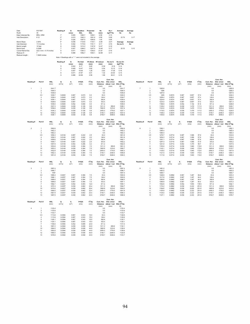
94
Date: 9/3/1997 Reading # Q Headbox Projected He Ke = Average AverageRun#: 30 (cms) EGL EGL (mm) 2g/V2*He He KeData Collected By: ERU, CRW 1* 0.005 1040.7 1038.1 2.56 3.15Inlet Description: # 12 2* 0.015 1062.3 1061.8 0.58 0.08 22.74 0.17
3* 0.026 1097.0 1095.6 1.45 0.06Barrel Slope: 2.00% 4* 0.036 1133.6 1134.1 -0.48 -0.01 Average AverageInlet Diameter: 11.5 inches 5 0.042 1170.9 1161.7 9.17 0.16 He (no f) KeBarrel Length: 12 feet 6 0.049 1212.2 1197.8 14.47 0.18Barrel Area: 0.0388 7 0.057 1266.5 1247.0 19.48 0.17 20.33 0.15Culvert Barrel Dia: 222.3 mm = 8.75 inches 8 0.071 1364.3 1336.4 27.87 0.16Reducer # : 7 9 0.086 1482.7 1440.1 42.68 0.17Reducer length : 7.0625 inches
Note = Readings with a " * " were not included in the average
Reading # Q He total Hf elbow Hf reducer He (no f) Ke (no f)=(cms) (mm) (mm) (mm) (mm) 2g/V2*He
5 0.042 9.17 0.60 0.39 8.18 0.146 0.049 14.47 0.82 0.54 13.12 0.167 0.057 19.48 1.26 0.83 17.39 0.168 0.071 27.87 2.01 1.32 24.54 0.149 0.086 42.68 2.58 1.69 38.41 0.15
Cum. Hor. Cum. Hor.Reading # Port # HGL Q A V=Q/A V2/2g Cum. Hor. Dist. w/out EGL Reading # Port # HGL Q A V=Q/A V2/2g Cum. Hor. Dist. w/out EGL
(mm) (m3/s) (m2) (m/s) (mm) Distance elbow + red HGL+V2/2g (mm) (m3/s) (m2) (m/s) (mm) Distance elbow + red HGL+V2/2g (mm) (mm) (ft) (mm) (mm) (mm)
1 1 1041.7 0.0 1041.7 7 1 1265.8 0.0 1265.82 1040.5 0.0 1040.5 2 1266 0.0 1266.03 1039.9 0.0 1039.9 3 1267.6 0.0 1267.6
3.5 1039.7 0.0049 0.067 0.073 0.3 63.4 1040.0 3.5 1205 0.0574 0.067 0.857 37.4 63.4 1242.44 1039.4 0.0049 0.067 0.073 0.3 149.4 1039.7 4 1209.4 0.0574 0.067 0.857 37.4 149.4 1246.85 1039.1 0.0049 0.067 0.073 0.3 292.6 1039.4 5 1224.6 0.0574 0.067 0.857 37.4 292.6 1262.06 1038.6 0.0049 0.067 0.073 0.3 433.4 1038.9 6 1224.0 0.0574 0.067 0.857 37.4 433.4 1261.47 1038.0 0.0049 0.052 0.094 0.5 611.2 1038.5 7 1186.9 0.0574 0.052 1.102 61.9 611.2 1248.89 1037.3 0.0049 0.039 0.126 0.8 1311.3 609.6 1038.1 9 1129.2 0.0574 0.039 1.479 111.5 1311.3 609.6 1240.7
10 1036.6 0.0049 0.039 0.126 0.8 1920.9 1219.2 1037.4 10 1123.5 0.0574 0.039 1.479 111.5 1920.9 1219.2 1235.011 1036.3 0.0049 0.039 0.126 0.8 2454.3 1778.0 1037.1 11 1118.0 0.0574 0.039 1.479 111.5 2454.3 1778.0 1229.512 1036.2 0.0049 0.039 0.126 0.8 3140.1 2438.4 1037.0 12 1109.4 0.0574 0.039 1.479 111.5 3140.1 2438.4 1220.913 1036.1 0.0049 0.039 0.126 0.8 3749.7 3048.0 1036.9 13 1105.6 0.0574 0.039 1.479 111.5 3749.7 3048.0 1217.1
Cum. Hor. Cum. Hor.Reading # Port # HGL Q A V=Q/A V2/2g Cum. Hor. Dist. w/out EGL Reading # Port # HGL Q A V=Q/A V2/2g Cum. Hor. Dist. w/out EGL
(mm) (m3/s) (m2) (m/s) (mm) Distance elbow + red HGL+V2/2g (mm) (m3/s) (m2) (m/s) (mm) Distance elbow + red HGL+V2/2g (mm) (mm) (ft) (mm) (mm) (mm)
2 1 1062.6 0.0 1062.6 8 1 1362.1 0.0 1362.12 1062.2 0.0 1062.2 2 1365.4 0.0 1365.43 1062.2 0.0 1062.2 3 1365.4 0.0 1365.4
3.5 1059.3 0.0149 0.067 0.222 2.5 63.4 1061.8 3.5 1276.7 0.0714 0.067 1.066 57.9 63.4 1334.64 1059.3 0.0149 0.067 0.222 2.5 149.4 1061.8 4 1252.3 0.0714 0.067 1.066 57.9 149.4 1310.25 1059.6 0.0149 0.067 0.222 2.5 292.6 1062.1 5 1301.1 0.0714 0.067 1.066 57.9 292.6 1359.06 1059.7 0.0149 0.067 0.222 2.5 433.4 1062.2 6 1297.3 0.0714 0.067 1.066 57.9 433.4 1355.27 1057.8 0.0149 0.052 0.286 4.2 611.2 1062.0 7 1241.9 0.0714 0.052 1.370 95.7 611.2 1337.69 1053.8 0.0149 0.039 0.384 7.5 1311.3 609.6 1061.3 9 1155.9 0.0714 0.039 1.840 172.6 1311.3 609.6 1328.5
10 1053.2 0.0149 0.039 0.384 7.5 1920.9 1219.2 1060.7 10 1143.1 0.0714 0.039 1.840 172.6 1920.9 1219.2 1315.711 1052.8 0.0149 0.039 0.384 7.5 2454.3 1778.0 1060.3 11 1135.0 0.0714 0.039 1.840 172.6 2454.3 1778.0 1307.612 1052.3 0.0149 0.039 0.384 7.5 3140.1 2438.4 1059.8 12 1121.5 0.0714 0.039 1.840 172.6 3140.1 2438.4 1294.113 1051.8 0.0149 0.039 0.384 7.5 3749.7 3048.0 1059.3 13 1117.8 0.0714 0.039 1.840 172.6 3749.7 3048.0 1290.4
Cum. Hor. Cum. Hor.Reading # Port # HGL Q A V=Q/A V2/2g Cum. Hor. Dist. w/out EGL Reading # Port # HGL Q A V=Q/A V2/2g Cum. Hor. Dist. w/out EGL
(mm) (m3/s) (m2) (m/s) (mm) Distance elbow + red HGL+V2/2g (mm) (m3/s) (m2) (m/s) (mm) Distance elbow + red HGL+V2/2g (mm) (mm) (ft) (mm) (mm) (mm)
3 1 1097.4 0.0 1097.4 9 1 1481.0 0.0 1481.02 1096.7 0.0 1096.7 2 1482.5 0.0 1482.53 1097 0.0 1097.0 3 1484.7 0.0 1484.7
3.5 1086.4 0.0257 0.067 0.384 7.5 63.4 1093.9 3.5 1348.9 0.0862 0.067 1.287 84.4 63.4 1433.34 1086.1 0.0257 0.067 0.384 7.5 149.4 1093.6 4 1317.8 0.0862 0.067 1.287 84.4 149.4 1402.25 1089.0 0.0257 0.067 0.384 7.5 292.6 1096.5 5 1393.6 0.0862 0.067 1.287 84.4 292.6 1478.06 1089.6 0.0257 0.067 0.384 7.5 433.4 1097.1 6 1390.9 0.0862 0.067 1.287 84.4 433.4 1475.37 1082.7 0.0257 0.052 0.493 12.4 611.2 1095.1 7 1302.6 0.0862 0.052 1.655 139.5 611.2 1442.19 1072.3 0.0257 0.039 0.662 22.4 1311.3 609.6 1094.7 9 1174.2 0.0862 0.039 2.222 251.6 1311.3 609.6 1425.8
10 1070.6 0.0257 0.039 0.662 22.4 1920.9 1219.2 1093.0 10 1164.6 0.0862 0.039 2.222 251.6 1920.9 1219.2 1416.211 1069.5 0.0257 0.039 0.662 22.4 2454.3 1778.0 1091.9 11 1155.9 0.0862 0.039 2.222 251.6 2454.3 1778.0 1407.512 1067.9 0.0257 0.039 0.662 22.4 3140.1 2438.4 1090.3 12 1134.0 0.0862 0.039 2.222 251.6 3140.1 2438.4 1385.613 1067.5 0.0257 0.039 0.662 22.4 3749.7 3048.0 1089.9 13 1127.1 0.0862 0.039 2.222 251.6 3749.7 3048.0 1378.7
Cum. Hor.Reading # Port # HGL Q A V=Q/A V2/2g Cum. Hor. Dist. w/out EGL
(mm) (m3/s) (m2) (m/s) (mm) Distance elbow + red HGL+V2/2g (mm) (mm) (ft)
4 1 1133.4 0.0 1133.42 1133.8 0.0 1133.83 1133.7 0.0 1133.7
3.5 1113.8 0.0364 0.067 0.543 15.0 63.4 1128.84 1113.8 0.0364 0.067 0.543 15.0 149.4 1128.85 1120.1 0.0364 0.067 0.543 15.0 292.6 1135.16 1120.1 0.0364 0.067 0.543 15.0 433.4 1135.17 1106.6 0.0364 0.052 0.699 24.9 611.2 1131.59 1087.2 0.0364 0.039 0.938 44.9 1311.3 609.6 1132.1
10 1084.5 0.0364 0.039 0.938 44.9 1920.9 1219.2 1129.411 1083.9 0.0364 0.039 0.938 44.9 2454.3 1778.0 1128.812 1080.0 0.0364 0.039 0.938 44.9 3140.1 2438.4 1124.913 1078.8 0.0364 0.039 0.938 44.9 3749.7 3048.0 1123.7

95
Cum. Hor.Reading # Port # HGL Q A V=Q/A V2/2g Cum. Hor. Dist. w/out EGL
(mm) (m3/s) (m2) (m/s) (mm) Distance elbow + red HGL+V2/2g (mm) (mm) (ft)
5 1 1170.6 0.0 1170.62 1171.1 0.0 1171.13 1170.9 0.0 1170.9
3.5 1138.7 0.0415 0.067 0.619 19.6 63.4 1158.34 1139.8 0.0415 0.067 0.619 19.6 149.4 1159.45 1150.4 0.0415 0.067 0.619 19.6 292.6 1170.06 1150.7 0.0415 0.067 0.619 19.6 433.4 1170.37 1129.8 0.0415 0.052 0.797 32.3 611.2 1162.19 1100.8 0.0415 0.039 1.070 58.3 1311.3 609.6 1159.1
10 1097.1 0.0415 0.039 1.070 58.3 1920.9 1219.2 1155.411 1095.4 0.0415 0.039 1.070 58.3 2454.3 1778.0 1153.712 1090.9 0.0415 0.039 1.070 58.3 3140.1 2438.4 1149.213 1089.4 0.0415 0.039 1.070 58.3 3749.7 3048.0 1147.7
Cum. Hor.Reading # Port # HGL Q A V=Q/A V2/2g Cum. Hor. Dist. w/out EGL
(mm) (m3/s) (m2) (m/s) (mm) Distance elbow + red HGL+V2/2g (mm) (mm) (mm)
6 1 1212.0 0.0 1212.02 1212.7 0.0 1212.73 1212 0.0 1212.0
3.5 1167 0.0488 0.067 0.728 27.0 63.4 1194.04 1168.3 0.0488 0.067 0.728 27.0 149.4 1195.35 1180.9 0.0488 0.067 0.728 27.0 292.6 1207.96 1182.4 0.0488 0.067 0.728 27.0 433.4 1209.47 1154.2 0.0488 0.052 0.937 44.7 611.2 1198.99 1113.0 0.0488 0.039 1.258 80.6 1311.3 609.6 1193.6
10 1109.1 0.0488 0.039 1.258 80.6 1920.9 1219.2 1189.711 1106.9 0.0488 0.039 1.258 80.6 2454.3 1778.0 1187.512 1099.6 0.0488 0.039 1.258 80.6 3140.1 2438.4 1180.213 1098.0 0.0488 0.039 1.258 80.6 3749.7 3048.0 1178.6

96
Date: 8/13/1997 Reading # Q Headbox Projected He Ke = Average AverageRun#: 29 (cms) EGL EGL (mm) 2g/V2*He He KeData Collected By: ERU 1* 0.010 952.8 948.7 4.07 1.85Inlet Description: # 12 2* 0.021 976.7 975.7 0.94 0.09 17.46 0.15
3* 0.034 1006.5 1010.7 -4.22 -0.15Barrel Slope: 1.50% 4* 0.037 1029.1 1021.4 7.70 0.23 Average AverageInlet Diameter: 11.5 inches 5 0.045 1063.0 1056.3 6.74 0.14 He (no f) KeBarrel Length: 12 feet 6 0.053 1100.9 1088.8 12.04 0.17Barrel Area: 0.04573 7 0.061 1139.9 1127.2 12.70 0.14 14.69 0.13Culvert Barrel Dia: 241.3 mm = 9.5" 8 0.068 1179.9 1160.3 19.57 0.17Reducer # : 6 9 0.081 1257.2 1233.8 23.36 0.15Reducer length : 7.0625 inches 10 0.089 1314.6 1284.2 30.34 0.16
Note = Readings with a " * " were not included in the average
Reading # Q He total Hf elbow Hf reducer He (no f) Ke (no f)=(cms) (mm) (mm) (mm) (mm) 2g/V2*He
5 0.045 6.74 0.81 0.44 5.49 0.116 0.053 12.04 1.04 0.56 10.43 0.157 0.061 12.70 1.56 0.84 10.30 0.118 0.068 19.57 1.71 0.92 16.94 0.159 0.081 23.36 2.60 1.41 19.35 0.12
10 0.089 30.34 3.04 1.64 25.65 0.13
Cum. Hor. Cum. Hor.Reading # Port # HGL Q A V=Q/A V2/2g Cum. Hor. Dist. w/out EGL Reading # Port # HGL Q A V=Q/A V2/2g Cum. Hor. Dist. w/out EGL
(mm) (m3/s) (m2) (m/s) (mm) Distance elbow + red HGL+V2/2g (mm) (m3/s) (m2) (m/s) (mm) Distance elbow + red HGL+V2/2g (mm) (mm) (ft) (mm) (mm) (mm)
1 1 953.1 0.0 953.1 7 1 1138.9 0.0 1138.92 952.6 0.0 952.6 2 1140.1 0.0 1140.13 952.6 0.0 952.6 3 1140.6 0.0 1140.6
3.5 950.8 0.0095 0.067 0.142 1.0 63.4 951.8 3.5 1072.7 0.0609 0.067 0.909 42.1 63.4 1114.84 951.6 0.0095 0.067 0.142 1.0 149.4 952.6 4 1066.1 0.0609 0.067 0.909 42.1 149.4 1108.25 950.7 0.0095 0.067 0.142 1.0 292.6 951.7 5 1093.7 0.0609 0.067 0.909 42.1 292.6 1135.86 950.6 0.0095 0.067 0.142 1.0 433.4 951.6 6 1093.6 0.0609 0.067 0.909 42.1 433.4 1135.77 949.6 0.0095 0.054 0.175 1.6 623.9 951.2 7 1054.9 0.0609 0.054 1.122 64.1 623.9 1119.09 946.4 0.0095 0.046 0.208 2.2 1311.3 609.6 948.6 9 1032.6 0.0609 0.046 1.333 90.5 1311.3 609.6 1123.1
10 946.3 0.0095 0.046 0.208 2.2 1920.9 1219.2 948.5 10 1025.6 0.0609 0.046 1.333 90.5 1920.9 1219.2 1116.111 946.3 0.0095 0.046 0.208 2.2 2454.3 1752.6 948.5 11 1023.1 0.0609 0.046 1.333 90.5 2454.3 1752.6 1113.612 946.0 0.0095 0.046 0.208 2.2 3140.1 2438.4 948.2 12 1016.6 0.0609 0.046 1.333 90.5 3140.1 2438.4 1107.113 946.1 0.0095 0.046 0.208 2.2 3749.7 3048.0 948.3 13 1012.7 0.0609 0.046 1.333 90.5 3749.7 3048.0 1103.2
Cum. Hor. Cum. Hor.Reading # Port # HGL Q A V=Q/A V2/2g Cum. Hor. Dist. w/out EGL Reading # Port # HGL Q A V=Q/A V2/2g Cum. Hor. Dist. w/out EGL
(mm) (m3/s) (m2) (m/s) (mm) Distance elbow + red HGL+V2/2g (mm) (m3/s) (m2) (m/s) (mm) Distance elbow + red HGL+V2/2g (mm) (mm) (ft) (mm) (mm) (mm)
2 1 976.3 0.0 976.3 8 1 1178.8 0.0 1178.82 976.8 0.0 976.8 2 1180.3 0.0 1180.33 976.9 0.0 976.9 3 1180.6 0.0 1180.6
3.5 969.5 0.0205 0.067 0.306 4.8 63.4 974.3 3.5 1096.9 0.0681 0.067 1.016 52.7 63.4 1149.64 970.8 0.0205 0.067 0.306 4.8 149.4 975.6 4 1104.4 0.0681 0.067 1.016 52.7 149.4 1157.15 971.3 0.0205 0.067 0.306 4.8 292.6 976.1 5 1123.1 0.0681 0.067 1.016 52.7 292.6 1175.86 971.9 0.0205 0.067 0.306 4.8 433.4 976.7 6 1121.8 0.0681 0.067 1.016 52.7 433.4 1174.57 967.9 0.0205 0.054 0.378 7.3 623.9 975.2 7 1074.9 0.0681 0.054 1.254 80.2 623.9 1155.19 964.9 0.0205 0.046 0.449 10.3 1311.3 609.6 975.2 9 1042.9 0.0681 0.046 1.490 113.2 1311.3 609.6 1156.1
10 964.4 0.0205 0.046 0.449 10.3 1920.9 1219.2 974.7 10 1034.5 0.0681 0.046 1.490 113.2 1920.9 1219.2 1147.711 964.2 0.0205 0.046 0.449 10.3 2454.3 1752.6 974.5 11 1033.2 0.0681 0.046 1.490 113.2 2454.3 1752.6 1146.412 963.2 0.0205 0.046 0.449 10.3 3140.1 2438.4 973.5 12 1023.8 0.0681 0.046 1.490 113.2 3140.1 2438.4 1137.013 962.9 0.0205 0.046 0.449 10.3 3749.7 3048.0 973.2 13 1021.5 0.0681 0.046 1.490 113.2 3749.7 3048.0 1134.7
Cum. Hor. Cum. Hor.Reading # Port # HGL Q A V=Q/A V2/2g Cum. Hor. Dist. w/out EGL Reading # Port # HGL Q A V=Q/A V2/2g Cum. Hor. Dist. w/out EGL
(mm) (m3/s) (m2) (m/s) (mm) Distance elbow + red HGL+V2/2g (mm) (m3/s) (m2) (m/s) (mm) Distance elbow + red HGL+V2/2g (mm) (mm) (ft) (mm) (mm) (mm)
3 1 1006.0 0.0 1006.0 9 1 1253.8 0.0 1253.82 1006.5 0.0 1006.5 2 1258.2 0.0 1258.23 1007 0.0 1007.0 3 1259.6 0.0 1259.6
3.5 992 0.0336 0.067 0.501 12.8 63.4 1004.8 3.5 1144.8 0.0806 0.067 1.203 73.8 63.4 1218.65 996.5 0.0336 0.067 0.501 12.8 292.6 1009.3 4 1127.1 0.0806 0.067 1.203 73.8 149.4 1200.96 996.7 0.0336 0.067 0.501 12.8 433.4 1009.5 5 1177.3 0.0806 0.067 1.203 73.8 292.6 1251.17 987.5 0.0336 0.054 0.619 19.5 623.9 1007.0 6 1177.4 0.0806 0.067 1.203 73.8 433.4 1251.29 982.3 0.0336 0.046 0.735 27.6 1311.3 609.6 1009.9 7 1113.3 0.0806 0.054 1.484 112.3 623.9 1225.6
10 980.6 0.0336 0.046 0.735 27.6 1920.9 1219.2 1008.2 9 1069.0 0.0806 0.046 1.764 158.5 1311.3 609.6 1227.511 980.2 0.0336 0.046 0.735 27.6 2454.3 1752.6 1007.8 10 1054.7 0.0806 0.046 1.764 158.5 1920.9 1219.2 1213.212 978.7 0.0336 0.046 0.735 27.6 3140.1 2438.4 1006.3 11 1055.7 0.0806 0.046 1.764 158.5 2454.3 1752.6 1214.213 977.8 0.0336 0.046 0.735 27.6 3749.7 3048.0 1005.4 12 1039.7 0.0806 0.046 1.764 158.5 3140.1 2438.4 1198.2
13 1035.9 0.0806 0.046 1.764 158.5 3749.7 3048.0 1194.4Cum. Hor.
Reading # Port # HGL Q A V=Q/A V2/2g Cum. Hor. Dist. w/out EGL Cum. Hor.(mm) (m3/s) (m2) (m/s) (mm) Distance elbow + red HGL+V2/2g Reading # Port # HGL Q A V=Q/A V2/2g Cum. Hor. Dist. w/out EGL
(mm) (mm) (ft) (mm) (m3/s) (m2) (m/s) (mm) Distance elbow + red HGL+V2/2g4 1 1028.9 0.0 1028.9 (mm) (mm) (mm)
2 1029 0.0 1029.0 10 1 1310.7 0.0 1310.73 1029.4 0.0 1029.4 2 1316.1 0.0 1316.1
3.5 1005 0.0370 0.067 0.552 15.5 63.4 1020.5 3 1316.9 0.0 1316.94 1007.6 0.0370 0.067 0.552 15.5 149.4 1023.1 3.5 1174.2 0.0892 0.067 1.331 90.3 63.4 1264.55 1012.2 0.0370 0.067 0.552 15.5 292.6 1027.7 4 1188.6 0.0892 0.067 1.331 90.3 149.4 1278.96 1012.0 0.0370 0.067 0.552 15.5 433.4 1027.5 5 1215.7 0.0892 0.067 1.331 90.3 292.6 1306.07 998.0 0.0370 0.054 0.681 23.7 623.9 1021.7 6 1215.6 0.0892 0.067 1.331 90.3 433.4 1305.99 988.9 0.0370 0.046 0.810 33.4 1311.3 609.6 1022.3 7 1135.0 0.0892 0.054 1.643 137.5 623.9 1272.5
10 986.3 0.0370 0.046 0.810 33.4 1920.9 1219.2 1019.7 9 1083.0 0.0892 0.046 1.952 194.2 1311.3 609.6 1277.211 985.8 0.0370 0.046 0.810 33.4 2454.3 1752.6 1019.2 10 1065.6 0.0892 0.046 1.952 194.2 1920.9 1219.2 1259.812 982.1 0.0370 0.046 0.810 33.4 3140.1 2438.4 1015.5 11 1067.1 0.0892 0.046 1.952 194.2 2454.3 1752.6 1261.313 988.0 0.0370 0.046 0.810 33.4 3749.7 3048.0 1021.4 12 1048.2 0.0892 0.046 1.952 194.2 3140.1 2438.4 1242.4
13 1044.2 0.0892 0.046 1.952 194.2 3749.7 3048.0 1238.4
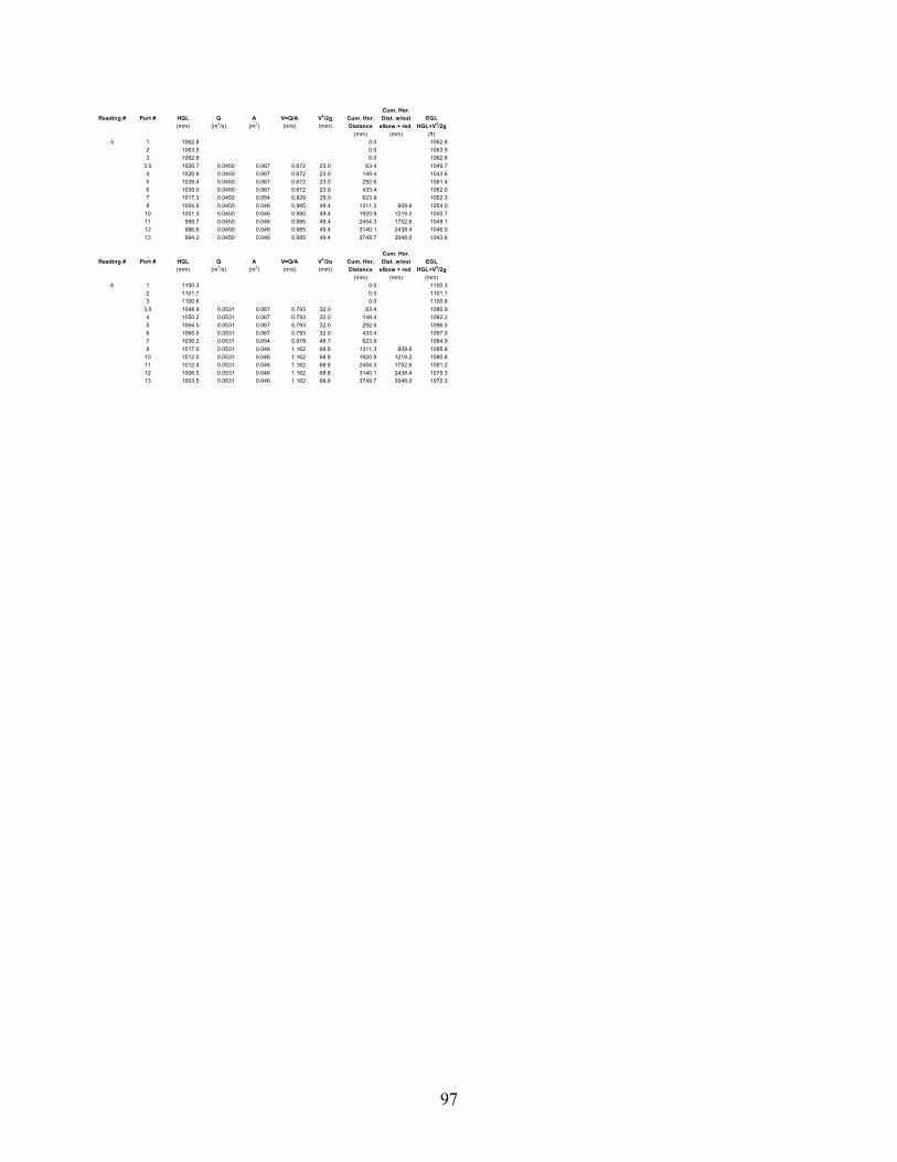
97
Cum. Hor.Reading # Port # HGL Q A V=Q/A V2/2g Cum. Hor. Dist. w/out EGL
(mm) (m3/s) (m2) (m/s) (mm) Distance elbow + red HGL+V2/2g (mm) (mm) (ft)
5 1 1062.8 0.0 1062.82 1063.5 0.0 1063.53 1062.8 0.0 1062.8
3.5 1026.7 0.0450 0.067 0.672 23.0 63.4 1049.74 1020.6 0.0450 0.067 0.672 23.0 149.4 1043.65 1038.4 0.0450 0.067 0.672 23.0 292.6 1061.46 1039.0 0.0450 0.067 0.672 23.0 433.4 1062.07 1017.3 0.0450 0.054 0.829 35.0 623.9 1052.39 1004.6 0.0450 0.046 0.985 49.4 1311.3 609.6 1054.0
10 1001.3 0.0450 0.046 0.985 49.4 1920.9 1219.2 1050.711 999.7 0.0450 0.046 0.985 49.4 2454.3 1752.6 1049.112 996.6 0.0450 0.046 0.985 49.4 3140.1 2438.4 1046.013 994.2 0.0450 0.046 0.985 49.4 3749.7 3048.0 1043.6
Cum. Hor.Reading # Port # HGL Q A V=Q/A V2/2g Cum. Hor. Dist. w/out EGL
(mm) (m3/s) (m2) (m/s) (mm) Distance elbow + red HGL+V2/2g (mm) (mm) (mm)
6 1 1100.3 0.0 1100.32 1101.7 0.0 1101.73 1100.6 0.0 1100.6
3.5 1048.9 0.0531 0.067 0.793 32.0 63.4 1080.94 1050.2 0.0531 0.067 0.793 32.0 149.4 1082.25 1064.5 0.0531 0.067 0.793 32.0 292.6 1096.56 1065.5 0.0531 0.067 0.793 32.0 433.4 1097.57 1036.2 0.0531 0.054 0.978 48.7 623.9 1084.99 1017.0 0.0531 0.046 1.162 68.8 1311.3 609.6 1085.8
10 1012.0 0.0531 0.046 1.162 68.8 1920.9 1219.2 1080.811 1012.4 0.0531 0.046 1.162 68.8 2454.3 1752.6 1081.212 1006.5 0.0531 0.046 1.162 68.8 3140.1 2438.4 1075.313 1003.5 0.0531 0.046 1.162 68.8 3749.7 3048.0 1072.3

98
Date: 8/6/1997 Reading # Q Headbox Projected He Ke = Average AverageRun#: 28 (cms) EGL EGL (mm) 2g/V2*He He KeData Collected By: JLK 1* 0.014 1020.9 1017.8 3.07 0.61Inlet Description: # 12 2* 0.027 1050.6 1049.7 0.89 0.05 13.22 0.15
3* 0.038 1083.1 1084.3 -1.21 -0.03Barrel Slope: 2.00% 4 0.046 1123.8 1115.6 8.12 0.16 Average AverageInlet Diameter: 11.5 inches 5 0.057 1175.7 1164.6 11.12 0.14 He (no f) KeBarrel Length: 12 feet 6 0.064 1212.7 1198.0 14.75 0.15Barrel Area: 0.04573 7 0.070 1248.5 1229.7 18.88 0.16 10.49 0.12Culvert Barrel Dia: 241.3 mm = 9.5"Reducer # : 5 Note = Readings with a " * " were not included in the averageReducer length : 14.8125 inches
Reading # Q He total Hf elbow Hf reducer He (no f) Ke (no f)=(cms) (mm) (mm) (mm) (mm) 2g/V2*He
4 0.046 8.12 0.74 0.80 6.58 0.135 0.057 11.12 1.18 1.28 8.66 0.116 0.064 14.75 1.53 1.66 11.55 0.127 0.070 18.88 1.77 1.92 15.18 0.13
Cum. Hor. Cum. Hor.Reading # Port # HGL Q A V=Q/A V2/2g Cum. Hor. Dist. w/out EGL Reading # Port # HGL Q A V=Q/A V2/2g Cum. Hor. Dist. w/out EGL
(mm) (m3/s) (m2) (m/s) (mm) Distance elbow + red HGL+V2/2g (mm) (m3/s) (m2) (m/s) (mm) Distance elbow + red HGL+V2/2g (mm) (mm) (ft) (mm) (mm) (ft)
1 1 1021.5 0.0 1021.5 5 1 1174.8 0.0 1174.82 1020.8 0.0 1020.8 2 1176.5 0.0 1176.53 1020.4 0.0 1020.4 3 1175.9 0.0 1175.9
3.5 1016.8 0.0144 0.067 0.215 2.4 63.4 1019.2 3.5 1118.2 0.0570 0.067 0.851 36.9 63.4 1155.14 1020.8 0.0144 0.067 0.215 2.4 149.4 1023.2 4 1108.9 0.0570 0.067 0.851 36.9 149.4 1145.85 1017.1 0.0144 0.067 0.215 2.4 292.6 1019.5 5 1136.4 0.0570 0.067 0.851 36.9 292.6 1173.36 1016.5 0.0144 0.067 0.215 2.4 433.4 1018.9 6 1135.9 0.0570 0.067 0.851 36.9 433.4 1172.87 1014.8 0.0144 0.061 0.237 2.9 623.9 1017.7 7 1111.5 0.0570 0.061 0.938 44.8 623.9 1156.38 1013.5 0.0144 0.051 0.281 4.0 782.7 1017.5 8 1092.0 0.0570 0.051 1.111 62.9 782.7 1154.99 1012.5 0.0144 0.046 0.315 5.1 1492.3 609.6 1017.6 9 1082.2 0.0570 0.046 1.247 79.3 1492.3 609.6 1161.510 1011.5 0.0144 0.046 0.315 5.1 2101.9 1219.2 1016.6 10 1076.8 0.0570 0.046 1.247 79.3 2101.9 1219.2 1156.111 1011.3 0.0144 0.046 0.315 5.1 2635.3 1752.6 1016.4 11 1075.1 0.0570 0.046 1.247 79.3 2635.3 1752.6 1154.412 1010.7 0.0144 0.046 0.315 5.1 3321.1 2438.4 1015.8 12 1070.6 0.0570 0.046 1.247 79.3 3321.1 2438.4 1149.913 1010.4 0.0144 0.046 0.315 5.1 3930.7 3048.0 1015.5 13 1066.8 0.0570 0.046 1.247 79.3 3930.7 3048.0 1146.1
Cum. Hor. Cum. Hor.Reading # Port # HGL Q A V=Q/A V2/2g Cum. Hor. Dist. w/out EGL Reading # Port # HGL Q A V=Q/A V2/2g Cum. Hor. Dist. w/out EGL
(mm) (m3/s) (m2) (m/s) (mm) Distance elbow + red HGL+V2/2g (mm) (m3/s) (m2) (m/s) (mm) Distance elbow + red HGL+V2/2g (mm) (mm) (ft) (mm) (mm) (mm)
2 1 1050.3 0.0 1050.3 6 1 1211.4 0.0 1211.42 1050.6 0.0 1050.6 2 1213.3 0.0 1213.33 1050.8 0.0 1050.8 3 1213.5 0.0 1213.5
3.5 1039.2 0.0267 0.067 0.399 8.1 63.4 1047.3 3.5 1140.3 0.0637 0.067 0.951 46.1 63.4 1186.44 1045.8 0.0267 0.067 0.399 8.1 149.4 1053.9 4 1153.1 0.0637 0.067 0.951 46.1 149.4 1199.25 1043.2 0.0267 0.067 0.399 8.1 292.6 1051.3 5 1163.0 0.0637 0.067 0.951 46.1 292.6 1209.16 1043.4 0.0267 0.067 0.399 8.1 433.4 1051.5 6 1162.1 0.0637 0.067 0.951 46.1 433.4 1208.27 1037.5 0.0267 0.061 0.439 9.8 623.9 1047.3 7 1132.8 0.0637 0.061 1.048 55.9 623.9 1188.78 1034.0 0.0267 0.051 0.520 13.8 782.7 1047.8 8 1107.7 0.0637 0.051 1.242 78.6 782.7 1186.39 1031.5 0.0267 0.046 0.584 17.4 1492.3 609.6 1048.9 9 1094.9 0.0637 0.046 1.394 99.0 1492.3 609.6 1193.910 1030.6 0.0267 0.046 0.584 17.4 2101.9 1219.2 1048.0 10 1087.2 0.0637 0.046 1.394 99.0 2101.9 1219.2 1186.211 1029.5 0.0267 0.046 0.584 17.4 2635.3 1752.6 1046.9 11 1087.3 0.0637 0.046 1.394 99.0 2635.3 1752.6 1186.312 1028.5 0.0267 0.046 0.584 17.4 3321.1 2438.4 1045.9 12 1078.6 0.0637 0.046 1.394 99.0 3321.1 2438.4 1177.613 1028.1 0.0267 0.046 0.584 17.4 3930.7 3048.0 1045.5 13 1075.3 0.0637 0.046 1.394 99.0 3930.7 3048.0 1174.3
Cum. Hor. Cum. Hor.Reading # Port # HGL Q A V=Q/A V2/2g Cum. Hor. Dist. w/out EGL Reading # Port # HGL Q A V=Q/A V2/2g Cum. Hor. Dist. w/out EGL
(mm) (m3/s) (m2) (m/s) (mm) Distance elbow + red HGL+V2/2g (mm) (m3/s) (m2) (m/s) (mm) Distance elbow + red HGL+V2/2g (mm) (mm) (ft) (mm) (mm) (mm)
3 1 1082.3 0.0 1082.3 7 1 1246.6 0.0 1246.62 1083.7 0.0 1083.7 2 1249.4 0.0 1249.43 1083.4 0.0 1083.4 3 1249.6 0.0 1249.6
3.5 1061.7 0.0379 0.067 0.566 16.3 63.4 1078.0 3.5 1160.3 0.0697 0.067 1.040 55.2 63.4 1215.54 1066.4 0.0379 0.067 0.566 16.3 149.4 1082.7 4 1156.0 0.0697 0.067 1.040 55.2 149.4 1211.25 1069.0 0.0379 0.067 0.566 16.3 292.6 1085.3 5 1184.6 0.0697 0.067 1.040 55.2 292.6 1239.86 1069.7 0.0379 0.067 0.566 16.3 433.4 1086.0 6 1188.1 0.0697 0.067 1.040 55.2 433.4 1243.37 1058.6 0.0379 0.061 0.623 19.8 623.9 1078.4 7 1149.1 0.0697 0.061 1.146 67.0 623.9 1216.18 1051.3 0.0379 0.051 0.739 27.8 782.7 1079.1 8 1122.1 0.0697 0.051 1.359 94.1 782.7 1216.29 1047.9 0.0379 0.046 0.829 35.1 1492.3 609.6 1083.0 9 1105.9 0.0697 0.046 1.525 118.6 1492.3 609.6 1224.510 1045.7 0.0379 0.046 0.829 35.1 2101.9 1219.2 1080.8 10 1098.6 0.0697 0.046 1.525 118.6 2101.9 1219.2 1217.211 1044.8 0.0379 0.046 0.829 35.1 2635.3 1752.6 1079.9 11 1097.1 0.0697 0.046 1.525 118.6 2635.3 1752.6 1215.712 1042.5 0.0379 0.046 0.829 35.1 3321.1 2438.4 1077.6 12 1087.2 0.0697 0.046 1.525 118.6 3321.1 2438.4 1205.813 1041.4 0.0379 0.046 0.829 35.1 3930.7 3048.0 1076.5 13 1083.9 0.0697 0.046 1.525 118.6 3930.7 3048.0 1202.5
Cum. Hor.Reading # Port # HGL Q A V=Q/A V2/2g Cum. Hor. Dist. w/out EGL
(mm) (m3/s) (m2) (m/s) (mm) Distance elbow + red HGL+V2/2g (mm) (mm) (ft)
4 1 1123.7 0.0 1123.72 1123.4 0.0 1123.43 1124.2 0.0 1124.2
3.5 1085 0.0457 0.067 0.682 23.7 63.4 1108.74 1094.6 0.0457 0.067 0.682 23.7 149.4 1118.35 1097.7 0.0457 0.067 0.682 23.7 292.6 1121.46 1098.0 0.0457 0.067 0.682 23.7 433.4 1121.77 1082.1 0.0457 0.061 0.752 28.8 623.9 1110.98 1070.1 0.0457 0.051 0.891 40.4 782.7 1110.59 1063.1 0.0457 0.046 1.000 51.0 1492.3 609.6 1114.110 1059.1 0.0457 0.046 1.000 51.0 2101.9 1219.2 1110.111 1058.0 0.0457 0.046 1.000 51.0 2635.3 1752.6 1109.012 1055.3 0.0457 0.046 1.000 51.0 3321.1 2438.4 1106.313 1053.4 0.0457 0.046 1.000 51.0 3930.7 3048.0 1104.4

99
Date: 8/1/1997 Reading # Q Headbox Projected He Ke = Average AverageRun#: 27 (cms) EGL EGL (mm) 2g/V2*He He KeData Collected By: JLK 1* 0.012 1025.3 1022.3 2.96 0.80Inlet Description: # 12 2* 0.026 1056.2 1055.9 0.28 0.02 12.16 0.15
3* 0.035 1089.4 1086.2 3.22 0.11Barrel Slope: 0.015 4 0.045 1132.0 1125.2 6.86 0.14 Average AverageInlet Diameter: 11.5 inches 5 0.057 1187.9 1176.1 11.83 0.15 He KeBarrel Length: 12 feet 6 0.070 1248.5 1230.7 17.79 0.15Barrel Area: 0.04573 9.92 0.12Culvert Barrel Dia: 241.3 mm = 9.5" Note = Readings with a " * " were not included in the averageReducer # : 5Reducer length : 14.8125 inches Reading # Q He Hf elbow Hf reducer He (no f) Ke (no f)
(cms) (mm) (mm) (mm) (mm) 2g/V2*He4 0.045 7.49 0.67 0.73 6.08 0.125 0.057 11.83 1.13 1.22 9.48 0.126 0.070 17.79 1.72 1.87 14.20 0.12
Cum. Hor. Cum. Hor.Reading # Port # HGL Q A V=Q/A V2/2g Cum. Hor. Dist. w/out EGL Reading # Port # HGL Q A V=Q/A V2/2g Cum. Hor. Dist. w/out EGL
(mm) (m3/s) (m2) (m/s) (mm) Distance elbow + red HGL+V2/2g (mm) (m3/s) (m2) (m/s) (mm) Distance elbow + red HGL+V2/2g (mm) (mm) (ft) (mm) (mm) (ft)
1 1 1025.6 0.0 1025.6 4 1 1130.8 0.0 1130.82 1025.2 0.0 1025.2 2 1132.5 0.0 1132.53 1025.1 0.0 1025.1 3 1132.8 0.0 1132.8
3.5 1021.8 0.0123 0.067 0.184 1.7 63.4 1023.5 3.5 1095.3 0.0452 0.067 0.675 23.2 63.4 1118.55 1021.7 0.0123 0.067 0.184 1.7 292.6 1023.4 5 1107.0 0.0452 0.067 0.675 23.2 292.6 1130.26 1021.6 0.0123 0.067 0.184 1.7 433.4 1023.3 6 1108.0 0.0452 0.067 0.675 23.2 433.4 1131.27 1020.6 0.0123 0.061 0.202 2.1 623.9 1022.7 7 1091.5 0.0452 0.061 0.743 28.2 623.9 1119.78 1019.3 0.0123 0.051 0.240 2.9 782.7 1022.2 8 1078.3 0.0452 0.051 0.881 39.6 782.7 1117.99 1018.4 0.0123 0.046 0.269 3.7 1492.3 609.6 1022.1 9 1073.3 0.0452 0.046 0.989 49.9 1492.3 609.6 1123.210 1018.0 0.0123 0.046 0.269 3.7 2101.9 1219.2 1021.7 10 1069.8 0.0452 0.046 0.989 49.9 2101.9 1219.2 1119.711 1018.0 0.0123 0.046 0.269 3.7 2635.3 1752.6 1021.7 11 1068.4 0.0452 0.046 0.989 49.9 2635.3 1752.6 1118.312 1017.5 0.0123 0.046 0.269 3.7 3321.1 2438.4 1021.2 12 1065.7 0.0452 0.046 0.989 49.9 3321.1 2438.4 1115.613 1017.3 0.0123 0.046 0.269 3.7 3930.7 3048.0 1021.0 13 1063.2 0.0452 0.046 0.989 49.9 3930.7 3048.0 1113.1
Cum. Hor. Cum. Hor.Reading # Port # HGL Q A V=Q/A V2/2g Cum. Hor. Dist. w/out EGL Reading # Port # HGL Q A V=Q/A V2/2g Cum. Hor. Dist. w/out EGL
(mm) (m3/s) (m2) (m/s) (mm) Distance elbow + red HGL+V2/2g (mm) (m3/s) (m2) (m/s) (mm) Distance elbow + red HGL+V2/2g (mm) (mm) (ft) (mm) (mm) (ft)
2 1 1056.0 0.0 1056.0 5 1 1186.9 0.0 1186.92 1056.3 0.0 1056.3 2 1189 0.0 1189.03 1056.3 0.0 1056.3 3 1187.8 0.0 1187.8
3.5 1046.1 0.0259 0.067 0.387 7.6 63.4 1053.7 3.5 1129.3 0.0574 0.067 0.857 37.4 63.4 1166.75 1049.3 0.0259 0.067 0.387 7.6 292.6 1056.9 5 1147.9 0.0574 0.067 0.857 37.4 292.6 1185.36 1049.7 0.0259 0.067 0.387 7.6 433.4 1057.3 6 1147.7 0.0574 0.067 0.857 37.4 433.4 1185.17 1044.8 0.0259 0.061 0.426 9.2 623.9 1054.0 7 1123.4 0.0574 0.061 0.944 45.4 623.9 1168.88 1041.0 0.0259 0.051 0.505 13.0 782.7 1054.0 8 1103.8 0.0574 0.051 1.119 63.8 782.7 1167.69 1039.1 0.0259 0.046 0.567 16.4 1492.3 609.6 1055.5 9 1092.4 0.0574 0.046 1.256 80.4 1492.3 609.6 1172.810 1038.0 0.0259 0.046 0.567 16.4 2101.9 1219.2 1054.4 10 1087.4 0.0574 0.046 1.256 80.4 2101.9 1219.2 1167.811 1037.3 0.0259 0.046 0.567 16.4 2635.3 1752.6 1053.7 11 1086.8 0.0574 0.046 1.256 80.4 2635.3 1752.6 1167.212 1036.5 0.0259 0.046 0.567 16.4 3321.1 2438.4 1052.9 12 1081.2 0.0574 0.046 1.256 80.4 3321.1 2438.4 1161.613 1036.3 0.0259 0.046 0.567 16.4 3930.7 3048.0 1052.7 13 1077.9 0.0574 0.046 1.256 80.4 3930.7 3048.0 1158.3
Cum. Hor. Cum. Hor.Reading # Port # HGL Q A V=Q/A V2/2g Cum. Hor. Dist. w/out EGL Reading # Port # HGL Q A V=Q/A V2/2g Cum. Hor. Dist. w/out EGL
(mm) (m3/s) (m2) (m/s) (mm) Distance elbow + red HGL+V2/2g (mm) (m3/s) (m2) (m/s) (mm) Distance elbow + red HGL+V2/2g (mm) (mm) (ft) (mm) (mm) (mm)
3 1 1088.6 0.0 1088.6 6 1 1247.0 0.0 1247.02 1089.7 0.0 1089.7 2 1248.6 0.0 1248.63 1089.9 0.0 1089.9 3 1249.8 0.0 1249.8
3.5 1068.9 0.0349 0.067 0.521 13.8 63.4 1082.7 3.5 1161.1 0.0695 0.067 1.037 54.8 63.4 1215.95 1074.8 0.0349 0.067 0.521 13.8 292.6 1088.6 5 1188.1 0.0695 0.067 1.037 54.8 292.6 1242.96 1075.8 0.0349 0.067 0.521 13.8 433.4 1089.6 6 1189.2 0.0695 0.067 1.037 54.8 433.4 1244.07 1065.9 0.0349 0.061 0.574 16.8 623.9 1082.7 7 1150.5 0.0695 0.061 1.143 66.6 623.9 1217.18 1059.1 0.0349 0.051 0.680 23.6 782.7 1082.7 8 1123.3 0.0695 0.051 1.355 93.5 782.7 1216.89 1055.3 0.0349 0.046 0.764 29.7 1492.3 609.6 1085.0 9 1108.6 0.0695 0.046 1.521 117.9 1492.3 609.6 1226.510 1053.2 0.0349 0.046 0.764 29.7 2101.9 1219.2 1082.9 10 1099.5 0.0695 0.046 1.521 117.9 2101.9 1219.2 1217.411 1052.9 0.0349 0.046 0.764 29.7 2635.3 1752.6 1082.6 11 1099.1 0.0695 0.046 1.521 117.9 2635.3 1752.6 1217.012 1050.7 0.0349 0.046 0.764 29.7 3321.1 2438.4 1080.4 12 1089.9 0.0695 0.046 1.521 117.9 3321.1 2438.4 1207.813 1049.7 0.0349 0.046 0.764 29.7 3930.7 3048.0 1079.4 13 1086.5 0.0695 0.046 1.521 117.9 3930.7 3048.0 1204.4