SERVICE HS26 UNIT INFORMATION - Heating & Air Parts · page 4 figure4 scroll how a scroll works...
18
SERVICE HS26 UNIT INFORMATION Page 1 1996 Lennox Industries Inc. Corp. 9622−L12 Litho U.S.A. EARLY/LATE MODEL SERIES Revised 04−2002 HS26 SERIES UNITS The HS26 is a high efficiency residential split−system conɢ densing unit which features a scroll compressor. Early model HS26 units (−261,−311,−411, and −461) are available in sizes ranging from 2 through 3−1/2 tons. Late model HS26 units (−018, −024, −030, −036, −042, −048 and −060) are available in sizes ranging from 1−1/2 through 5 tons. The series is designed for use with an expansion valve in the indoor unit.This manual is divided into sections which discuss the major components, refrigerant system, chargɢ ing procedure, maintenance and operation sequence. Inɢ formation in this manual covers both early and late model HS26 units. All specifications in this manual are subject to change. Late Model HS26 shown ELECTRICAL DATA (Early Model) SPECIFICATIONS (Early Model) Model No. HS26−261 HS26−311 HS26−411 HS26−461 Outdoor Coil Condenser Fan HCFC−22 (charge furnished) Face area (sq.ft.) Tube diameter (in.) No. of Rows Fins per inch Diameter (in.) No. of Blades Motor hp Cfm RPM Watts Liquid line connection Suction line connection HS26−261 HS26−311 HS26−411 HS26−461 Model No. Line voltage data − 60hz./1 phase Compressor Rated load amps Power factor Locked rotor amps Condenser Fan Motor Full load amps Locked rotor amps Max fuse or c.b. size (amps) *Minimum circuit ampacity outer / inner *Refer to National Electrical Code Manual to determine wire, fuse and disconnect size requirements. NOTE − Extremes of operating range are plus 10% and minus 5% of line voltage 11.8/5.4 15.9/5.5 15.9/15.3 21.6/20.8 3/8 3/8 3/8 3/8 1.36 1.36 2.0 2.0 20 20 20 20 24 24 24 24 3 3 3 3 1/6 1/6 1/6 1/6 3150 3150 3000 3230 820 820 820 820 210 210 230 205 7lbs. 11oz. 8lbs. 1oz. 9lbs. 0oz. 11lbs. 3oz. 3/8 3/8 3/8 3/8 3/4 3/4 3/4 1ɢ1/8 208/230V 208/230V 208/230V 208/230V 11.6 13.5 18.0 20 .96 .96 .96 .97 62.5 76.0 90.5 107 1.1 1.1 1.1 1.1 2.0 2.0 2.0 2.0 25 30 40 45 15.6 18.0 23.6 26.1 *Refrigerant charge sufficient for 25 ft. (7.6 m) length of refrigerant lines.
Transcript of SERVICE HS26 UNIT INFORMATION - Heating & Air Parts · page 4 figure4 scroll how a scroll works...

SERVICE HS26UNIT
INFORMATION
Page 1 1996 Lennox Industries Inc.
Corp. 9622−L12
Litho U.S.A.
EARLY/LATEMODEL SERIESRevised 04−2002
HS26 SERIES UNITSThe HS26 is a high efficiency residential split−system con�
densing unit which features a scroll compressor. Early
model HS26 units (−261,−311,−411, and −461) are available
in sizes ranging from 2 through 3−1/2 tons. Late model
HS26 units (−018, −024, −030, −036, −042, −048 and −060)
are available in sizes ranging from 1−1/2 through 5 tons.
The series is designed for use with an expansion valve in
the indoor unit.This manual is divided into sections which
discuss the major components, refrigerant system, charg�
ing procedure, maintenance and operation sequence. In�
formation in this manual covers both early and late model
HS26 units.
All specifications in this manual are subject to change.
Late ModelHS26 shown
ELECTRICAL DATA (Early Model)
SPECIFICATIONS (Early Model)
Model No. HS26−261 HS26−311 HS26−411 HS26−461
OutdoorCoil
CondenserFan
HCFC−22 (charge furnished)
Face area (sq.ft.)
Tube diameter (in.)
No. of Rows
Fins per inch
Diameter (in.)
No. of Blades
Motor hp
Cfm
RPM
Watts
Liquid line connection
Suction line connection
HS26−261 HS26−311 HS26−411 HS26−461Model No.
Line voltage data − 60hz./1 phase
Compressor
Rated load amps
Power factor
Locked rotor amps
Condenser
Fan Motor
Full load amps
Locked rotor amps
Max fuse or c.b. size (amps)
*Minimum circuit ampacity
outer / inner
*Refer to National Electrical Code Manual to determine wire, fuse and disconnect size requirements.
NOTE − Extremes of operating range are plus 10% and minus 5% of line voltage
11.8/5.4 15.9/5.5 15.9/15.3 21.6/20.8
3/8 3/8 3/8 3/8
1.36 1.36 2.0 2.0
20 20 20 20
24 24 24 24
3 3 3 3
1/6 1/6 1/6 1/6
3150 3150 3000 3230
820 820 820 820
210 210 230 205
7lbs. 11oz. 8lbs. 1oz. 9lbs. 0oz. 11lbs. 3oz.
3/8 3/8 3/8 3/8
3/4 3/4 3/4 1�1/8
208/230V 208/230V 208/230V 208/230V
11.6 13.5 18.0 20
.96 .96 .96 .97
62.5 76.0 90.5 107
1.1 1.1 1.1 1.1
2.0 2.0 2.0 2.0
25 30 40 45
15.6 18.0 23.6 26.1
*Refrigerant charge sufficient for 25 ft. (7.6 m) length of refrigerant lines.

Page 2
SPECIFICATIONS (Late Model)
Model No. HS26�018 HS26�024 HS26�030 HS26�036 HS26�042 HS26�048 HS26�060
Net face areaOuter coil 11.9 (1.11) 11.9 (1.11) 16.0 (1.59) 16.0 (1.59) 16.0 (1.59) 18.2 (1.69) 21.6 (2.01)
Net face area� sq. ft. (m2) Inner coil 5.5 (0.51) 5.5 (0.51) 5.6 (0.52) 13.3 (1.24) 13.3 (1.24) 13.3 (1.24) 20.8 (1.93)
CondenserCoil
Tube diameter � in. (mm) 5/16 (7.9) 5/16 (7.9) 5/16 (7.9) 5/16 (7.9) 5/16 (7.9) 5/16 (7.9) 5/16 (7.9)Coil
No. of rows 1.48 1.48 1.36 1.86 1.86 1.75 2
Fins per inch (m) 22 (866) 22 (866) 22 (866) 22 (866) 22 (866) 22 (866) 22 (866)
Dia. − in. (mm) no. of blades 20 (508) − 4 20 (508) − 4 24 (610) − 3 24 (610) − 3 24 (610) − 324 (610) �
424 (610) �
4
CondenserMotor hp (W) 1/10 (75) 1/6 (124) 1/6 (124) 1/6 (124) 1/6 (124) 1/4 (187) 1/4 (187)
CondenserFan Cfm (L/s) 2500 (1180) 2450 (1155) 3150 (1485) 3150 (1485) 3000 (1415) 3900 (1840) 4200 (1980)
Rpm 825 825 825 825 825 820 820
Watts 160 210 225 225 230 310 350
*Refrigerant � HCFC�22 charge furnished4 lbs. 1 oz.(1.84 kg)
4 lbs. 1 oz.(1.84 kg)
5 lbs. 1 oz.(2.30 kg)
5 lbs. 13 oz.(2.64 kg)
6 lbs. 11 oz.(3.03 kg)
7 lbs. 5 oz.(3.32 kg)
10 lbs. 8 oz.(4.76 kg)
Liquid line (o.d.) � in. (mm) sweat 3/8 (9.5) 3/8 (9.5) 3/8 (9.5) 3/8 (9.5) 3/8 (9.5) 3/8 (9.5) 3/8 (9.5)
Suction line (o.d.) in. � (mm) sweat 5/8 (16) 3/4 (19) 3/4 (19) 3/4 (19) 7/8 (22.2) 7/8 (22.2) 1�1/8 (28.6)
Shipping weight � lbs. (kg) 1 package 177 (80) 185 (84) 192 (87) 221 (100) 231 (105) 274 (124) 308 (140)
*Refrigerant charge sufficient for 25 ft. (7.6 m) length of refrigerant lines.
ELECTRICAL DATA (Late Model)
Model No. HS26�018 HS26�024 HS26�030 HS26�036 HS26�042
Line voltage data � 60hz208/230v
1ph208/230v
1ph208/230v
1ph208/230v
1ph208/230v
3ph208/230v
1ph208/230v
3ph
Rated load amps 8.4 10.3 13.5 16.0 10.3 18.0 12.5
Compressor Power factor 0.97 0.96 0.96 0.96 0.82 0.94 0.82
Locked rotor amps 47 56 72.5 88 77 104 88
Condenser Coil Full load amps 0.8 1.1 1.1 1.1 1.1 1.1 1.1Condenser CoilFan Motor Locked rotor amps 1.6 2.0 2.0 2.0 2.0 2.0 2.0
Rec. max. fuse or circuit breaker size (amps) 15 20 30 35 20 40 25
*Minimum circuit ampacity 13 14 18 21.3 14 23.6 16.4
*Refer to National or Canadian Electrical Code manual to determine wire, fuse and disconnect size requirements.NOTE � Extremes of operating range are plus 10% and minus 5% of line voltage.
ELECTRICAL DATA (Late Model)
Model No. HS26�048 HS26�060
Line voltage data � 60hz208/230v
1ph208/230v
3ph460v3ph
208/230v1ph
208/230v3ph
460v3ph
Rated load amps 23.7 13.5 7.4 28.8 17.4 9.0
Compressor Power factor .97 .87 .87 .97 .85 .85
Locked rotor amps 129 99 49.5 169 123 62
Condenser Coil Full load amps 1.7 1.7 1.1 1.7 1.7 1.1Condenser CoilFan Motor Locked rotor amps 3.1 3.1 2.2 3.1 3.1 2.2
Rec. max. fuse or circuit breaker size (amps) 50 30 15 60 40 20
*Minimum circuit ampacity 31.4 18.6 10.4 37.7 23.5 12.4
*Refer to National or Canadian Electrical Code manual to determine wire, fuse and disconnect size requirements.NOTE � Extremes of operating range are plus 10% and minus 5% of line voltage.

Page 3
FIGURE 1
SCROLL COMPRESSOR
DISCHARGE
SUCTION
Early Model HS26 Compressor shown
I−APPLICATIONAll major components (indoor blower and coil) must be
matched according to Lennox recommendations for the
compressor to be covered under warranty. Refer to the
Engineering Handbook for approved system matchups. A
misapplied system will cause erratic operation and can re�
sult in early compressor failure.
II−SCROLL COMPRESSORThe scroll compressor design is simple, efficient and re�quires few moving parts. A cutaway diagram of the scrollcompressor is shown in figure 1.The scrolls are located inthe top of the compressor can and the motor is located justbelow. The oil level is immediately below the motor.
The scroll is a simple compression concept centered
around the unique spiral shape of the scroll and its inherent
properties. Figure 2 shows the basic scroll form. Two iden�
tical scrolls are mated together forming concentric spiral
shapes (figure 3 ). One scroll remains stationary, while the
other is allowed to �orbit" (figure 4). Note that the orbiting
scroll does not rotate or turn but merely �orbits" the station�
ary scroll.
FIGURE 2
SCROLL FORM
FIGURE 3
STATIONARY SCROLL
ORBITING SCROLL
DISCHARGE
SUCTION
CROSS−SECTION OF SCROLLS
TIPS SEALED BYDISCHARGE PRESSURE
DISCHARGEPRESSURE
The counterclockwise orbiting scroll draws gas into the out�er crescent shaped gas pocket created by the two scrolls(figure 4 − 1). The centrifugal action of the orbiting scrollseals off the flanks of the scrolls (figure 4 − 2). As the orbitingmotion continues, the gas is forced toward the center of thescroll and the gas pocket becomes compressed (figure 4−3). When the compressed gas reaches the center, it is dis�charged vertically into a chamber and discharge port in thetop of the compressor (figure1). The discharge pressureforcing down on the top scroll helps seal off the upper andlower edges (tips) of the scrolls (figure 3 ). During a singleorbit, several pockets of gas are compressed simultaneous�ly providing smooth continuous compression.The scroll compressor is tolerant to the effects of liquid re�turn. If liquid enters the scrolls, the orbiting scroll is allowedto separate from the stationary scroll. The liquid is workedtoward the center of the scroll and is discharged. If thecompressor is replaced, conventional Lennox cleanuppractices must be used.
Due to its efficiency, the scroll compressor is capable ofdrawing a much deeper vacuum than reciprocating com�pressors. Deep vacuum operation can cause internal fu�site arcing resulting in damaged internal parts and will re�sult in compressor failure. Never use a scroll compressorfor evacuating or �pumping−down" the system. This type ofdamage can be detected and will result in denial of warran�ty claims.NOTE − During operation, the head of a scroll compressormay be hot since it is in constant contact with dischargegas.

Page 4
FIGURE4
SCROLL
HOW A SCROLL WORKS
SUCTION SUCTION
SUCTION
MOVEMENT OF ORBIT
STATIONARY SCROLL
ORBITING
CRESCENTSHAPED GAS
HIGHPRESSURE
GAS
DISCHARGEPOCKET
FLANKSSEALED BY
CENTRIFUGALFORCE
1 2
3 4
SUCTION
INTERMEDIATEPRESSURE
GAS
SUCTIONPOCKET
III−UNIT COMPONENTS
A−TransformerThe contactor coil, time delay and temperature sensorare all energized by 24VAC supplied by the indoor unit.All other controls in the outdoor unit are powered by linevoltage. Refer to unit wiring diagram. The HS26 is notequipped with an internal line voltage to 24V transform�er.
B−ContactorThe compressor is energized by a contactor located in thecontrol box. Early model units use single−pole contactors.Latemodel single−phase units use single pole and two−pole con�tactors. See wiring diagrams for specific unit. Late modelthree−phase units use three−pole contactors. The contactor isenergized by indoor thermostat terminal Y when thermostatdemand is present.
CAUTIONSome HS26 units use single−pole contactors. Oneleg of the compressor, capacitor and condenserfan are connected to line voltage at all times. Po�tential exists for electrical shock resulting in inju�ry or death. Remove all power at disconnect be�fore servicing
ELECTROSTATIC DISCHARGE (ESD)
Precautions and Procedures
CAUTIONElectrostatic discharge can affect electroniccomponents. Take precautions during unit instal�lation and service to protect the unit’s electroniccontrols. Precautions will help to avoid controlexposure to electrostatic discharge by puttingthe unit, the control and the technician at thesame electrostatic potential. Neutralize electro�static charge by touching hand and all tools on anunpainted unit surface before performing anyservice procedure.

Page 5
C−TD1−1 Time Delay (Early Models)Some early model HS26 units are equipped with a Lennox−built TD1−1 time delay located in the control box (figure 5).The time delay is electrically connected between thermostatterminal Y and the compressor contactor. On initial thermo�stat demand, the compressor contactor is delayed for 8.5seconds. At the end of the delay, the compressor is allowedto energize. When thermostat demand is satisfied, the timedelay opens the circuit to the compressor contactor coil andthe compressor is de−energized.
The time delay performs no other functions. Without thedelay it would be possible to short cycle the compressor. Ascroll compressor, when short cycled, can run backward ifhead pressure is still high. It does not harm a scroll com�pressor to run backward, but it could cause a nuisance tripof safety limits (internal overload). For this reason, if aTD1−1 delay should fail, it must be replaced. Do not bypassthe control.
D−TOC Timed Off Control (Early and Late Models)Some early and all late model HS26 units are equipped witha TOC, timed off control.The TOC is located in the controlbox (figure 6). The time delay is electrically connected be�tween thermostat terminal Y and the compressor contactor.Between cycles, the compressor contactor is delayed for 5minutes + 2 minutes. At the end of the delay, the compres�sor is allowed to energize. When thermostat demand is sat�isfied, the time delay opens the circuit to the compressorcontactor coil and the compressor is de−energized. Withoutthe time delay it would be possible to short cycle the com�pressor. A scroll compressor, when short cycled, can runbackward if head pressure is still high. It does not harm ascroll compressor to run backward, but it could cause a nui�sance tripout of safety limits. For this reason, if a TOC fails itmust be replaced.
DANGERDO NOT ATTEMPT TO REPAIR THE TD1−1 OR THETOC CONTROL. UNSAFE OPERATION WILL RE�SULT. IF THE CONTROL IS FOUND TO BE INOP�ERATIVE, SIMPLY REPLACE IT.
FIGURE 5
HS26 UNIT COMPONENTS (EARLY MODEL)
CONTACTOR
LIQUID LINESERVICE VALVE
SUCTIONVALVE
COMPRESSOR
COMPRESSORTERMINAL BOX
THERMOMETERWELL
DUAL CAPACITOR
AND GAUGE PORT
AND GAUGE PORT
LOW PRES�SURE SWITCH
COMPRESSORTEMPERATURE
SENSOR
CONDENSER FAN(NOT SHOWN)
TOP OF CABINET
ACCUMULATOR(��411, �461 only
all others equippedwith suction muffler)
HIGHPRESSURE
SWITCH
TD−1 TIME DELAYOR T.O.C. TIMED OFFCONTROL

Page 6
FIGURE 6
CONDENSER FAN(NOT SHOWN)
TOP OF CABINET
CONTACTOR
THERMOME�TER
WELL
TERMINAL BOX
LIQUID LINESERVICE VALVE
AND GAUGEPORT
SUCTION VALVEAND GAUGE PORT
COMPRESSOR
LOW PRESSURESWITCH
HIGH PRESSURESWITCH
GROUND LUG
PARTS ARRANGEMENT FOR HS26 (LATE MODEL)TIMED OFF CONTROL (TOC)
DUAL CAPACITOR
E−CompressorTables1 and 2 show the specifications for compressorsused in HS26 series units.
F−Compressor High Temperature Limit (Early Models)Each scroll compressor in the HS26−261, −311, −411, −461is equipped with a compressor high temperature limit lo�cated on the outside top of the compressor. The sensor is aSPST thermostat which opens when the discharge tem�perature exceeds 280�F + 8�F (138�C + 4.5�C) on a tem�perature rise. When the switch opens, the circuit to thecompressor contactor and the time delay is de−energizedand the unit shuts off. The switch automatically resetswhen the compressor temperature drops below 130�F +14�F. (54�C + 8�C)
The sensor can be accessed by prying off the snap plug ontop of the compressor (see figure 7). Make sure to securelyseal the limit after replacement. The limit pigtails are lo�cated inside the unit control box. Figure 8 shows the ar�rangement of compressor line voltage terminals and dis�charge sensor pigtails.
Table 1 (Early Models)
HS 26Unit
Vac Phase LRA RLA Oil fl.oz.
−261 208/230 1 62.5 11.6 28*
−311 208/230 1 76.0 13.5 28*
−411 208/230 1 90.5 18.0 34*
−461 208/230 1 107 20.0 38*
*Shipped with conventional white oil (Sontex 200LT). 3GS oil may beused if additional oil is required.
Table 2 (Late Models)HS26Unit
Vac Phase LRA RLA Oil fl. oz.
−018 208/230 1 47.0 8.4 38*
−024 208/230 1 56.0 10.3 30*
−030 208/230 1 72.5 13.5 30*
−036 208/230 1 88.0 16.0 42*
−042 208/230 1 104.0 18.0 42*
−048 208/230 1 129.0 23.7 53*
−060 208/230 1 169.0 28.8 50*
−036 208/230 3 88.8 10.3 42*
−042 208/230 3 77.0 12.5 42*
−048 208/230 3 99.0 13.5 53*
−048 460 3 49.5 7.4 53*
−060 208/230 3 123.0 17.4 53*
−060 460 3 62.0 9.0 53*
*Shipped with conventional white oil (Sontex 200LT). 3GS oil may beused if additional oil is required.
Page 7
FIGURE 7
COMPRESSOR HIGH TEMPERATURE LIMIT CHANGEOUT (EARLY MODELS ONLY)
Instructions
1� With power off, disconnect wiring to limit.2� Dislodge limit/cap assembly from compressor. Plastic cap and silicone seal
will break away. Discard all pieces.3� Remove thermostat and grommet from compressor. Thoroughly clean all
blue adhesive and white silicone thermal grease from compressor and theinside of the thermostat tube. Thermostat tube should be clean and free ofdebris.
4� Using Lennox kit 93G8601, dip end of thermostat into plastic bottle labeled�Silicone Thermal Grease G.E. #G641" and coat end of thermostat. Care�fully insert thermostat/grommet assembly into thermostat tube of compres�sor. Avoid contact with top of compressor.
5� Clean excess thermal grease from under cap lip and top lip of compressoropening.
6� Install protector assembly as shown, feeding wire leads through channelprovided in cap.
7� Apply a bead of sealant around lip of cap at area shown in illustration andinto the thermostat tube area.
8� Install assembly as shown. Align wires to channel in compressor shell. Suf�ficient force is required to snap plastic cap into tube to engage all threeprongs.
9� Re�connect wiring.10�After completing thermostat replacement, discard remaining parts.
PLASTIC CAP
PRONG
GROMMET
SEALANT(BLUE)
COMPRESSOR
THERMALGREASE(WHITE)
LIMIT(THERMOSTAT)
G−High/Low Pressure SwitchA manual�reset single�pole single�throw high pressure switch
located in the liquid line, shuts off the compressor when liquid
line pressure rises above the factory setting. The switch is nor�
mally closed and is permanently adjusted to trip (open) at 410
+ 10 psi. See figure 5 or 6 for switch location
COMPRESSOR TERMINAL BOX
CS
R
COMPRESSORTERMINALS
FIGURE 8
WARNINGCOMPRESSOR MUST BE GROUNDED. DONOT OPERATE WITHOUT PROTECTIVE COV�ER OVER TERMINALS. DISCONNECT ALLPOWER BEFORE REMOVING PROTECTIVECOVER. DISCHARGE CAPACITORS BEFORESERVICING UNIT. COMPRESSOR WIRING DIA�GRAM IS FURNISHED INSIDE COMPRESSORTERMINAL BOX COVER. FAILURE TO FOL�LOW THESE PRECAUTIONS COULD CAUSEELECTRICAL SHOCK RESULTING IN INJURYOR DEATH.
DISCHARGE TEMPERATURESENSOR WIRES
TO CONTROL BOX(TO COMP. TERM. BOX IN
�461 UNITS)EARLY MODELS ONLY
An auto�reset single�pole single�throw low pressure switchlocated in the suction line shuts off the compressor whensuction pressure drops below the factory setting. Theswitch is normally closed and is permanently adjusted totrip (open) at 25 + 5 psi. The switch automatically resetswhen suction line pressure rises above 55 + 5 psi. See fig�ure 5 or 6 for switch location.
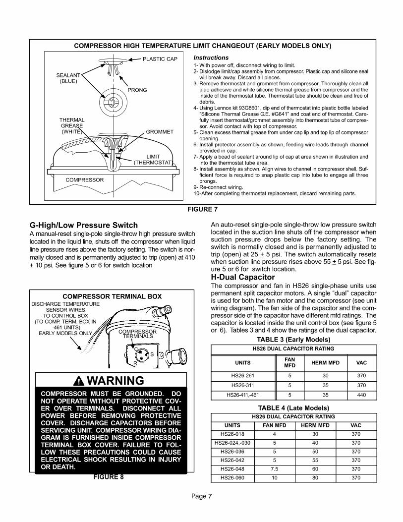
H−Dual CapacitorThe compressor and fan in HS26 single−phase units usepermanent split capacitor motors. A single �dual" capacitoris used for both the fan motor and the compressor (see unitwiring diagram). The fan side of the capacitor and the com�pressor side of the capacitor have different mfd ratings. Thecapacitor is located inside the unit control box (see figure 5or 6). Tables 3 and 4 show the ratings of the dual capacitor.
TABLE 3 (Early Models)
HS26 DUAL CAPACITOR RATING
UNITSFANMFD
HERM MFD VAC
HS26−261 5 30 370
HS26−311 5 35 370
HS26−411,−461 5 35 440
TABLE 4 (Late Models)
HS26 DUAL CAPACITOR RATING
UNITS FAN MFD HERM MFD VAC
HS26−018 4 30 370
HS26−024,−030 5 40 370
HS26−036 5 50 370
HS26−042 5 55 370
HS26−048 7.5 60 370
HS26−060 10 80 370

Page 8
I−Condenser Fan Motor
All units use single−phase PSC fan motors which require arun capacitor. The �FAN" side of the dual capacitor is usedfor this purpose. The specifications tables on page 1 and 2of this manual show the specifications of outdoor fans usedin HS26s. In all units, the outdoor fan is controlled by thecompressor contactor. See figure 9 if condenser fan motorreplacement is necessary.
FIGURE 9
"A" SEE TABLE 5 FAN
GUARD
Condenser fan and motor Wiring
Drip loop
TABLE 5
HS26 UNIT "A" DIM. + 1/8" Fan Blade Ven�dor
018 024 261 7/8"Lau
−018, −024, −261, 7/8"Revcor
−030, −311, −036,1 1/16"
Lau030, 311, 036,−411, −042, −461 1−1/16"
Revcor
0481−3/4" Lau
−0481−1/2" Revcor
060 1 3/16"Lau
−060 1−3/16"Revcor
IV−REFRIGERANT SYSTEMA−Plumbing
Field refrigerant piping consists of liquid and suction linesfrom the outdoor unit (sweat connections). Use LennoxL10 or L15 series line sets as shown in table 6 or 7 for field−fabricated refrigerant lines. Refer to the piping section ofthe Lennox Service Unit Information Manual (SUI−803−L9)for proper size, type and application of field−fabricatedlines.Separate discharge and suction service ports are providedat the compressor for connection of gauge manifold duringcharging procedure.
TABLE 6 (Early Models)HS26UNIT
LIQUIDLINE
SUCTIONLINE
L10 LINESET
L15 LINESET
−261, −311,−411
3/8 in. (10 MM)
3/4 in.(19 mm)
L10−4120ft. − 50 ft.(6m − 15 m)
L15 − 4120 ft. − 50 ft.(6 m − 15 m)
−4613/8 in.
(10 MM)1−1/8 in.(29 m)
Field Fabricated
Field Fabricated
−5113/8 in.
(10 MM)7/8 in.(22 m)
L10−6530 ft. − 50 ft.(9 m − 15m)
L15−6530 ft. − 50 ft.(9 m − 15m)
−6513/8 in.
(10 MM)1−1/8 in.(29 m)
Field Fabricated
Field Fabricated
TABLE 7 (Late Models)HS26UNIT
LIQUIDLINE
SUCTIONLINE
L10 LINESET
L15 LINESET
−0183/8 in.
(10 mm)5/8 in.
(16 mm)
L10−2620ft. − 50 ft.(6m − 15 m)
L15 − 2620 ft. − 50 ft.(6 m − 15 m)
−024 −030−036
3/8 in. (10 mm)
3/4 in. (19 mm)
L10−4120 ft. − 50 ft.(6m − 15 m)
L15−4120 ft. − 50 ft.(6m − 15m)
−042 −0483/8 in.
(10 mm)7/8 in.(22 m)
L10−6530 ft. − 50 ft.(9 m − 15m)
L15−6530 ft. − 50 ft.(9 m − 15m)
−0603/8 in.
(10 mm)1−1/8 in.(29 m)
Field Fabricated
Field Fabricated
KNIFE EDGE SEAL
STEM CAP
SERVICEPORTCAP
TO LINESET
TOCONDENSER
COIL
LIQUID LINE SERVICE VALVE
IMPORTANT
A schrader valve is not provided on the liquid lineservice port. Valve must be backseated to turn offpressure to service port.
FIGURE 10
VALVE STEMUSE SERVICE
WRENCH(PART #18P66,
54B64 or 12P95)
SERVICE PORT OPEN TOLINE SET WHEN FRONTSEATED AND CLOSED
(OFF) WHEN BACKSEATED
NO SCHRADER
B−Service Valves (Early Models)The liquid line and suction line service valves and gaugeports are accessible by removing the compressor accesscover. Full service liquid and suction line valves areused.The service ports are used for leak testing, evacuat�ing, charging and checking charge.
1 − Liquid Line Service ValveA full�service liquid line valve made by one of severalmanufacturers may be used. All liquid line service valvesfunction the same way, differences are in construction.Valves are not rebuildable. If a valve has failed it must bereplaced. The liquid line service valve is illustrated in figure10.

Page 9
The valve is equipped with a service port. There is no
schrader valve installed in the liquid line service port. A ser�
vice port cap is supplied to seal off the port.
The liquid line service valve is a front and back seating
valve. When the valve is backseated, the service port is not
open.The service port cap can be removed and gauge
connections can be made.
To Access Service Port:
1− Remove the stem cap. Use a service wrench
(part #18P66, 54B64 or 12P95) to make sure the ser�
vice valve is backseated.
CAUTIONThe service port cap is used to seal the liquidline service valve. Access to service portrequires backseating the service valve toisolate the service port from the system. Failureto do so will cause refrigerant leakage.
IMPORTANTA schrader valve is not provided on the liquid lineservice port. Valve must be backseated to turn offpressure to service port.
2− Remove service port cap and connect high pressure
gauge to service port.
3− Using service wrench, open valve stem (one turn
clockwise) from backseated position.
4− When finished using port, backseat stem with service
wrench. Tighten firmly.
5− Replace service port and stem cap. Tighten finger
tight, then tighten an additional 1/6 turn.
To Close Off Service Port:
1− Using service wrench, backseat valve.
a − Turn stem counterclockwise.
b − Tighten firmly, but do not overtighten.
To Open Liquid Line Service Valve:
1− Remove the stem cap with an adjustable wrench.
2− Using service wrench, backseat valve.
a − Turn stem counterclockwise until backseated.
b − Tighten firmly, but do not overtighten.
3− Replace stem cap, finger tighten then tighten an addi�
tional 1/6 turn.
To Close Liquid Line Service Valve:
1− Remove the stem cap with an adjustable wrench.
2− Turn the stem in clockwise with a service wrench to
front seat the valve. Tighten firmly.
3− Replace stem cap, finger tighten then tighten an addi�
tional 1/6 turn.
2 − Suction Line (Seating Type) Service ValveA full service non�backseating suction line service valve isused on all early HS26 series units (except �461). Differentmanufacturers of valves may be used. All suction line servicevalves function the same way, differences are in construction.
Valves are not rebuildable. If a valve has failed it must bereplaced. The suction line service valve is illustrated infigure 11.
The valve is equipped with a service port. A schradervalve is factory installed. A service port cap is suppliedto protect the schrader valve from contamination andassure a leak free seal.
SUCTION LINE SERVICE VALVE (VALVEOPEN)
FIGURE 11
SCHRADER VALVE
SERVICE PORT
SERVICEPORTCAP
STEM CAP
SNAP RINGINSERT HEX WRENCHHERE (PART #49A71
ANDSERVICE WRENCH)
SUCTION LINE SERVICE VALVE (VALVECLOSED)
INLET(FROM INDOOR COIL)
OUTLET(TO
COMPRESSOR)
KNIFEEDGESEAL
SCHRADER VALVEOPEN TO LINE SET
WHEN VALVE IS CLOSED(FRONT SEATED)
SERVICE PORT
SERVICEPORTCAP
(VALVEFRONT SEATED)
SNAP RING
STEMCAP
OUTLET(TO
COMPRESSOR)
KNIFE EDGE SEAL
INLET(FROM INDOOR COIL)
INSERTHEX WRENCH HERE(PART #49A71 AND
SERVICEWRENCH)
To Access Schrader Port:
1− Remove service port cap with an adjustable wrench.
2− Connect gauge to the service port.
3− When testing is completed, replace service portcap. Tighten finger tight, then tighten an additional1/6 turn.
To Open Suction Line Service Valve:
1− Remove stem cap with an adjustable wrench.
2− Using service wrench and 5/16" hex head extension(part #49A71) back the stem out counterclockwise untilthe valve stem just touches the retaining ring.

Page 10
Do not attempt to backseat this valve. Attempts tobackseat this valve will cause snap ring to explodefrom valve body under pressure of refrigerant.Personal injury and unit damage will result.
DANGER
3− Replace stem cap and tighten firmly. Tighten fingertight, then tighten an additional 1/6 turn.
To Close Suction Line Service Valve:
1− Remove stem cap with an adjustable wrench.
2− Using service wrench and 5/16" hex head extension(part #49A71) turn stem in clockwise to seat the valve.Tighten firmly, but do not overtighten.
3− Replace stem cap. Tighten finger tight, then tighten anadditional 1/6 turn.
3 − Suction Line (Ball Type) Service ValveA ball�type full service valve is used on the early modelHS26�461 units. This valve is manufactured by Aeroquip. Allsuction line service valves function the same way, differencesare in construction. Valves are not rebuildable. If a valvehas failed it must be replaced. A ball valve is illustratedin figure 12.
The ball valve is equipped with a service port. A schrad�er valve is factory installed. A service port cap is sup�plied to protect the schrader valve from contaminationand assure a leak free seal.
SUCTION LINE (BALL TYPE) SERVICE VALVE(VALVE OPEN)
FIGURE 12
SCHRADER VALVE
SERVICE PORT
SERVICEPORTCAP
STEM CAP
INLET(FROM INDOOR COIL)
OUTLET(TO
COMPRESSOR)
STEM
USE ADJUSTABLE WRENCHROTATE STEM CLOCKWISE 90� TO CLOSE
ROTATE STEM COUNTER�CLOCKWISE 90� TO OPEN
BALL(SHOWN OPEN)
C−Service Valves (Late Models)
The liquid line and suction line service valves and gaugeports are accessible by removing the compressor accesscover. Full service liquid and suction line valves are used.See figures13 and 14. The service ports are used for leaktesting, evacuating, charging and checking charge. Ser�vice valves have a factory installed schrader valve. A ser�vice port cap is supplied to protect the schrader valve fromcontamination and assure a leak free seal. Valves are notrebuildable. If a valve has failed it must be replaced.
SCHRADER
VALVE
SER�VICEPORT
SERVICEPORTCAP
INSERT HEXWRENCH HERE
INLET (TOINDOOR COIL)
OUTLET (TOCOMPRESSOR)
STEM CAP
SCHRADER VALVE OPENTO LINE SET WHEN VALVE
IS CLOSED (FRONTSEATED)
SERVICEPORT
SERVICEPORT CAP
RETAINING RING STEM CAP
OUTLET (TOCOMPRESSOR)
INSERT HEXWRENCH HERE
LIQUID/VAPOR LINE SERVICEVALVE
(VALVE CLOSED)
(VALVE FRONTSEATED)
INLET(TO INDOOR COIL)
FIGURE 13
LIQUID LINE SERVICE VALVE ALL UNITS VAPOR LINE SERVICE VALVE
−018, −024, −030, −036, −042, −048(VALVE OPEN)
To Access Schrader Port:
1− Remove service port cap with an adjustable wrench.
2− Connect gauge to the service port.
3− When testing is completed, replace service port cap.
Tighten finger tight, then an additional 1/6 turn.

Page 11
To Open Liquid or Suction Line Service Valve:
1− Remove stem cap with an adjustable wrench.
2− Using service wrench and 5/16" hex head extension
back the stem out counterclockwise until the valve stem
just touches the retaining ring.
3− Replace stem cap and tighten finger tight, then tighten
an additional 1/6 turn.
Do not attempt to backseat this valve. Attempts tobackseat this valve will cause snap ring to explodefrom valve body under pressure of refrigerant.Personal injury and unit damage will result.
DANGER
To Close Liquid or Suction Line Service Valve:
1− Remove stem cap with an adjustable wrench.
2−Using service wrench and 5/16" hex head extension, turn
stem clockwise to seat the valve. Tighten firmly, but do not
overtighten.
3− Replace stem cap. Tighten finger tight, then tighten an
additional 1/6 turn.
SUCTION LINE (BALL TYPE) SERVICE VALVEHS26−060 MODEL ONLY
(VALVE OPEN)
FIGURE 14
SCHRADER VALVE
SERVICE PORT
SERVICEPORTCAP
STEM CAP
INLET(FROM INDOOR COIL)
OUTLET(TO
COMPRESSOR)
STEM
USE ADJUSTABLE WRENCHROTATE STEM CLOCKWISE 90� TO CLOSE
ROTATE STEM COUNTER�CLOCKWISE 90� TO OPEN
BALL(SHOWN OPEN)
V−CHARGING
The unit is factory−charged with the amount of R�22 refrig�erant indicated on the unit rating plate. This charge isbased on a matching indoor coil and outdoor coil with a 25foot (7.6m) line set. For varying lengths of line set, refer totable 8 for refrigerant charge adjustment for both, early andlate model HS26 units. A blank space is provided on theunit rating plate to list actual field charge.
TABLE 8
LIQUID LINE SET DIAMETER
Ounce per 5 ft. (ml per mm) adjustfrom 25 ft. (7.6m) line set*
5/16 in. (8mm) 2 ounce per 5 ft. (60 ml per 1524 mm)
3/8 in. (10 mm) 3 ounce per 5 ft. (90 ml per 1524 mm)
If line set is greater than 25 ft. (7.6m) add this amount. If line set is less
than 25 ft. (7.6m) subtract this amount.
Units are designed for line sets up to 50 ft. (15m).Consult Len�nox Refrigerant Piping Manual for line sets over 50 ft. (15m).
IMPORTANTIf line length is greater than 25 feet (7.6m), add thisamount. If line length is less than 25feet ( 7.6m),subtract this amount.
A−Leak Testing 1− Attach gauge manifold and connect a drum of dry nitro�
gen to center port of gauge manifold. 2− Add a small amount of refrigerant to the lines and
coil. Open high pressure valve on gauge manifoldand pressurize line set and indoor coil to 150 psig(1034 kPa).
WARNINGDanger of Explosion.Can cause injury, death and equipmentdamage.When using dry nitrogen, use a pres�sure−reducing regulator, set at 150 psig(1034 kPa) or less to prevent excessivepressure.
3− Check lines and connections for leaks.
NOTE�If electronic leak detector is used, add a trace of re�frigerant to nitrogen for detection by leak detector. 4− Release nitrogen pressure from the system, correct
any leaks and recheck.
B−Evacuating the System
Evacuating the system of non−condensables is critical for
proper operation of the unit. Non−condensables are defined
as any gas that will not condense under temperatures and
pressures present during operation of an air conditioning
system. Non−condensables such as water vapor, combine
with refrigerant to produce substances that corrode copper
piping and compressor parts.

Page 12
1− Attach gauge manifold and connect vacuum pump(with vacuum gauge) to center port of gauge man�ifold. With both gauge manifold service valves open,start pump and evacuate evaporator and refrigerantlines.
IMPORTANTA temperature vacuum gauge, mercury vacuum(U−tube), or thermocouple gauge should be used.The usual Bourdon tube gauges are not accurateenough in the vacuum range.
IMPORTANTThe compressor should never be used to evacu�ate a refrigeration or air conditioning system.
CAUTIONDanger of Equipment Damage. Avoid deep vacuumoperation. Do not use compressors to evacuate asystem. Extremely low vacuums can cause internalarcing and compressor failure. Damage caused bydeep vacuum operation will void warranty.
2− Evacuate the system to an absolute pressure of.92 inches of mercury, 23 mm of mercury, or 23,000microns.
3− After system has been evacuated to an absolutepressure of .92 inches of mercury, 23 mm of mercury,or 23,000 microns, close manifold valve to centerport.
4− Stop vacuum pump and disconnect from gauge man�ifold. Attach a drum of dry nitrogen to center port ofgauge manifold, open drum valve slightly to purge line,then break vacuum in system to 3 psig (20.7 kPa) pres�sure by opening manifold high pressure valve to centerport.
5− Close nitrogen drum valve, disconnect drum frommanifold center port and release nitrogen pressurefrom system.
6− Reconnect vacuum pump to manifold center porthose. Evacuate the system to an absolute pressureless than .197 inches of mercury, 5 mm of mercury, or5000 microns, then turn off vacuum pump. If the abso�lute pressure rises above .197 inches of mercury, 5mm of mercury, or 5000 microns within a 20−minuteperiod after stopping vacuum pump, repeat step 6. Ifnot, evacuation is complete.This evacuation procedure is adequate for a newinstallation with clean and dry lines. If excessive mois�ture is present, the evacuation process may be re�quired more than once.
7− After evacuation has been completed, close gaugemanifold service valves. Disconnect vacuum pumpfrom manifold center port and connect refrigerantdrum. Pressurize system slightly with refrigerant tobreak vacuum.
IMPORTANTUse tables 9 and 10 as a general guide for perform�ing maintenance checks. Table 9 is not a procedurefor charging the system. Minor variations in thesepressures may be expected due to differences ininstallations. Significant deviations could mean thatthe system is not properly charged or that a problemexists with some component in the system. Usedprudently, tables 9 and 10 could serve as a usefulservice guide.
C−ChargingTABLE 9 (Early Models)
NORMAL OPERATING PRESSURES
OUTDOOR TEMP. (�F)
HS26−261 HS26−311 HS26−411
65
7585
95
LIQ.+ 10
SUC.+ 10
PSIG PSIG
LIQ.+ 10
SUC.+ 10
PSIG PSIG
LIQ.+ 10
SUC.+ 10
PSIG PSIG
105
LIQ.+ 10
SUC.+ 10
PSIG PSIG
HS26−461
141
163
191
220
255
77
79
80
82
83
140
160
186
216
254
69
74
78
80
81
141
167
195
225
260
75
77
79
80
81
140
170
170
223
261
62
77
77
80
81

Page 13
TABLE 10 (Late Models)
OUTDOORTEMP. (�F)
75
76
77
78
79
142
167
194
223
256
Suct.+ 5 psig
Liq.+10 psig
65
75
85
95
105
76
77
78
79
80
143
168
196
226
260
Suct.+5 psig
Liq.+10 psig
72
73
74
76
77
139
163
191
223
255
Suct.+5 psig
Liq.+10 psig
70
71
72
73
75
138
164
192
223
256
Suct.+5 psig
Liq.+10 psig
74
75
76
78
79
141
166
186
227
261
Suct.+5 psig
Liq.+10 psig
71
72
73
75
77
130
156
175
216
251
Suct.+5 psig
Liq.+10 psig
73
74
75
76
77
171
196
225
232
251
Suct.+5 psig
Liq.+10 psig
HS26−018 HS26−024 HS26−030 HS26−036 HS26−042 HS26−048 HS26−060
NORMAL OPERATING PRESSURES
If the system is completely void of refrigerant, the recom�
mended and most accurate method of charging is to weigh
the refrigerant into the unit according to the total amount
shown on the unit nameplate. Also refer to the SPECIFI�
CATIONS tables on page 1 for early model HS26 units and
page 2 for late model HS26 units.
If weighing facilities are not available or if unit is just low on
charge, the following procedure applies.
The following procedures are intended as a general guide
for use with expansion valve systems only. For best re�
sults, indoor temperature should be between
70 °F and 80 °F. Outdoor temperature should be 60 °F or
above. Slight variations in charging temperature and pres�
sure should be expected. Large variations may indicate a
need for further servicing.
APPROACH METHOD (TXV SYSTEMS)(Ambient Temperature of 60�F [16�C] or Above)
1− Connect gauge manifold. Connect an upright HCFC�22drum to center port of gauge manifold.
IMPORTANTThe following procedure requires accurate read�ings of ambient (outdoor) temperature, liquid tem�perature and liquid pressure for proper charging.Use a thermometer with accuracy of +2 °F and apressure gauge with accuracy of +5 PSIG.
2− Record outdoor air (ambient) temperature.
3− Operate indoor and outdoor units in cooling mode. Allowunits to run until system pressures stabilize.
4− Make sure thermometer well is filled with mineral oil be�fore checking liquid line temperature.
5− Place thermometer in well and read liquid line tempera�ture. Liquid line temperature should be a few degreeswarmer than the outdoor air temperature. Tables 11 and12 show how many degrees warmer the liquid line tem�perature should be.
Add refrigerant to make the liquid line cooler.
Recover refrigerant to make the liquid line warmer.
TABLE 11
APPROACH METHOD − EXPANSION VALVES SYSTEM
MODELLiquid Line �F (�C) Warmer ThanOutside Ambient Temperature
H2−26−261,311 3 + 1 (1.6 + .5)
HS26−411 4 + 1 (2.2 + .5)
HS26−461 6 + 1 (3.3 + .5)
TABLE 12
APPROACH METHOD − EXPANSION VALVES SYSTEMS
MODELLiquid Line �F (�C) Warmer Than
Outside Ambient Temperature
HS26−036, 048 5 + 1 (2.8 + .5)
HS26−018, 030, 042, 060 8 + 1 (4.44 + .5)
HS26−024 9 + 1 (5+ .5)
6− When unit is properly charged liquid line pressuresshould approximate those in table 9 or table 10.
D−Oil Charge
Refer to Table 1 and 2 on page 6.

Page 14
VI−MAINTENANCE
WARNINGElectric shock hazard. Can cause injuryor death. Before attempting to performany service or maintenance, turn theelectrical power to unit OFF at discon�nect switch(es). Unit may have multiplepower supplies.
At the beginning of each heating or cooling season, the
system should be cleaned as follows:
A−Outdoor Unit
1− Clean and inspect condenser coil. (Coil may be
flushed with a water hose).
2− Visually inspect all connecting lines, joints and coils for
evidence of oil leaks.
IMPORTANTIf insufficient heating or cooling occurs, the unit
should be gauged and refrigerant charge
checked.
B−Indoor Coil
1− Clean coil if necessary.
2− Check connecting lines and coil for oil leaks.
3−Check condensate line and clean if necessary.
C−Indoor Unit
1− Clean or change filters.
2− Adjust blower cooling speed. Check static pressure drop
over coil to determine correct blower CFM. Refer to Len�
nox Engineering Handbook.
3− Belt Drive Blowers���Check condition/tension.
4− Check all wiring for loose connections.
5− Check for correct voltage at unit.
6− Check amp−draw on blower motor.
Unit nameplate_________Actual_________.

Page 15
VII−DIAGRAMS / OPERATING SEQUENCE
A−Unit Diagram HS26−261/461−1P (Early Models)
UNIT DIAGRAM
1
2
3
4
Operation Sequence
1− WARNING−Early HS26 units use single−
pole contactors. Capacitor terminal
�COM," orange condenser fan wire and
red �R" compressor wire are all con�
nected to L2 at all times. Remove all
power at disconnect before servicing.
2− Cooling demand energizes thermostat ter�
minal Y. Voltage from terminal Y passes
through discharge temperature sensor
(compressor thermostat) and low pressure
switch to energize time delay terminal 2.
3− Time delay action is at the beginning of a
thermostat demand. When energized, time
delay TD1−1 delays 8.5 seconds before en�
ergizing TD1−1 terminal 3. When TD1−1 ter�
minal 3 is energized, the contactor coil is en�
ergized.
4− When compressor contactor is energized,
N.O. contactor contacts close to energize
compressor terminal �C" (black wire) and
black condenser fan motor wire. Condens�
er fan and compressor immediately begin
operating.

Page 16
B−Unit Diagram HS26−018/060−2P (Late Models)
Operation Sequence
1− Cooling demand energizes thermostat terminal Y. Voltage from terminal Y passes through low pressure
switch and the timed off control (TOC), which energizes K1 compressor contactor coil (provided 5 minute
delay is satisfied).
2− K1−1 and K1−2 contacts close energizing B1 compressor and B4 outdoor fan.
3− When cooling demand is satisfied, K1−1 and K1−2 contacts open de−energizing compressor and outdoor fan.
Timed off control begins 5 minute off time.

Page 17
C−Unit Diagram HS26−018/060−3 & 4−P (Late Models)
Operation Sequence
1− Cooling demand energizes thermostat terminal Y. Voltage from terminal Y passes through low pressure
switch and the timed off control (TOC), which energizes K1 compressor contactor coil (provided 5 minute
delay is satisfied).
2− K1−1 and K1−2 contacts close energizing B1 compressor and B4 outdoor fan.
3− When cooling demand is satisfied, K1−1 and K1−2 contacts open de−energizing compressor and outdoor fan.
Timed off control begins 5 minute off time.

Page 18
C−Unit Diagram HS26−036/060−1Y, −048/−060−1G Three−phase (Late Models)
Operation Sequence
1− Cooling demand energizes thermostat terminal Y. Voltage from terminal Y passes through low pressure
switch and timed off control (T.O.C.), which energizes K1 compressor contactor coil (provided 5 minute delay
is satisfied.)
2− K1−1, K1−2 and K1−3 contacts close energizing B1 compressor and B4 outdoor fan.
3− When cooling demand is satisfied, K1−1, K1−2 and K1−3 contacts open de−energizing compressor and out�
door fan. Timed off control begins 5 minute off time.
NOTE−Three−phase compressors must be phased correctly. Compressor noise will be significantly higher if phasing is
incorrect. Compressor will operate backwards so unit will not provide cooling. Continued backward operation will cause
compressor to cycle on internal protector.