Model YLAA Air-Cooled Scroll Compressor Liquid Chillers ... · Wiring Diagram ... The chiller has...
70
Form 150.62-EG5 (509) Model YLAA Air-Cooled Scroll Compressor Liquid Chillers Style B Round Tube Condenser Coils 246 – 527 kW 60 Hz R-410A
Transcript of Model YLAA Air-Cooled Scroll Compressor Liquid Chillers ... · Wiring Diagram ... The chiller has...
Form 150.62-EG5 (509)
Model YLAA Air-Cooled Scroll Compressor Liquid ChillersStyle B
Round Tube Condenser Coils246 – 527 kW
60 HzR-410A

� jOHNSON CONTROLS
Form 150.62-EG5 (509) ......................................................................................................................................................................................... 1Specifications ....................................................................................................................................................................................................... 3Microcomputer Control Center ........................................................................................................................................................................... 4Accessories and Options .................................................................................................................................................................................... 6Major Unit Components ....................................................................................................................................................................................... 8Nomenclature........................................................................................................................................................................................................ 9Design Parameters ............................................................................................................................................................................................. 10Water Pressure Drop ...........................................................................................................................................................................................11Selection Criteria and Procedures .................................................................................................................................................................... 12Pump Selection Criteria ..................................................................................................................................................................................... 14Pump Pressure Drop Curves............................................................................................................................................................................. 16Single Pump Curves........................................................................................................................................................................................... 18Dual Pump Curves.............................................................................................................................................................................................. 19Ratings - 60 Hz .................................................................................................................................................................................................... 20Part Load Ratings – Standard Efficiency ......................................................................................................................................................... 28Part Load Ratings – High Efficiency ................................................................................................................................................................. 29Physical Data - English ...................................................................................................................................................................................... 30Dimensions – Four Fan Units ............................................................................................................................................................................ 32Dimensions – Six Fan Units .............................................................................................................................................................................. 33Dimensions – Eight Fan Units ........................................................................................................................................................................... 34Isolator Locations ............................................................................................................................................................................................... 35Isolator Details .................................................................................................................................................................................................... 37Electrical Notes................................................................................................................................................................................................... 40Electrical Data w/o Pumps ................................................................................................................................................................................. 42Electrical Data w/ Pumps ................................................................................................................................................................................... 44Wiring Diagram ................................................................................................................................................................................................... 52Elementary Wiring ............................................................................................................................................................................................. 54Condenser Fan Mapping and Sequencing ....................................................................................................................................................... 56Compressor Wiring ............................................................................................................................................................................................ 57Power Options Connection Diagram ................................................................................................................................................................ 58Power Panel ........................................................................................................................................................................................................ 59Dual Pump Wiring ............................................................................................................................................................................................... 60Wiring .................................................................................................................................................................................................................. 61MicroPanel Connections .................................................................................................................................................................................... 62Application Data ................................................................................................................................................................................................. 65Guide Specifications .......................................................................................................................................................................................... 66
Table of Contents

FORM 150.62-EG5 (509)
�jOHNSON CONTROLS
SpecificationsGENERAL
The 70 - 150 Ton (�46 - 5�7kW) YLAA models are shipped complete from the factory ready for installation and use.
The unit is pressure-tested, evacuated, and fully charged with a zero Ozone Depletion Potential Refrigerant R-410A and includes an initial oil charge. After assembly, a complete operational test is performed with water flowing through the evaporator to assure that the refrigeration circuit operates correctly.
The unit structure is heavy-gauge, galvanized steel. This galvanized steel is coated with baked-on powder paint, which, when subjected to ASTM B117 1000 hour, salt spray testing, yields a minimum ASTM 1654 rating of “6”. Units are designed in accordance with NFPA 70 (Na-tional Electric Code), ASHRAE/ANSI 15 Safety code for mechanical refrigeration, ASME and rated in accordance with ARI Standard 550/590.
COMPRESSORS
The chiller has suction-gas cooled, hermetic, scroll com-pressors. The YLAA compressors incorporate a compliant scroll design in both the axial and radial direction. All rotating parts are statically and dynamically balanced. A large internal volume and oil reservoir provides greater liquid tolerance. Compressor-crankcase heaters are also included for extra protection against liquid migration.
EvAPORATOR
The evaporator is equipped with a heater controlled by a separate thermostat. The heater provides freeze pro-tection for the evaporator down to -�0oF (-�9°C) ambient. The evaporator is covered with 3/4” flexible, closed-cell,
foam insulation (K=0.�5).
The water baffles are constructed of brass to resist corro-sion. The removable heads allow access to the internally enhanced, seamless, copper tubes. Vent and drain con-nections are included.
Water inlet and outlet connections are grooved for com-patibility with field supplied ANSI/AWWA C-606 cou-plings.
CONDENSER
Coils – Fin and tube condenser coils of seamless, inter-nally-enhanced, high-condensing-coefficient, corrosion resistant copper tubes are arranged in staggered rows,
mechanically expanded into aluminum fins. Integral sub-cooling is included. The design working pressure of the coil is 650 PSIG (45 barg).
Fans – The condenser fans are composed of corrosion resistant aluminum hub and glass-fiber-reinforced poly-propylene composite blades molded into a low-noise airfoil section. They are designed for maximum efficiency and are statically and dynamically balanced for vibration-free operation. They are directly driven by independent motors, and positioned for vertical air discharge. The fan guards are constructed of heavy-gauge, rust-resistant, coated steel. All blades are statically and dynamically balanced for vibration-free operation.
Motors – The fan motors are Totally Enclosed Air-Over, squir-rel-cage type, current protected. They feature ball bearings that are double-sealed and permanently lubricated.

4 jOHNSON CONTROLS
All controls are contained in a NEMA �R/1� cabinet with hinged outer door and includes:
Liquid Crystal Display with Light Emitting Diode back-lighting for outdoor viewing: Two display lines Twenty characters per line
Color coded 1�-button non-tactile keypad with sections for:
DISPLAY/PRINT of typical information: Chilled liquid temperatures Ambient temperature System pressures (each circuit) Operating hours and starts (each compressor) Print calls up to the liquid crystal display: Operating data for the systems History of fault shutdown data for up to the last six fault shutdown conditions An RS-��� port, in conjunction with this press-to-print button, is provided to permit the capability of hard copy print-outs via a separate printer (by others).
ENTRY section to: ENTER setpoints or modify system values
SETPOINTS updating can be performed to: Chilled liquid temperature setpoint and range Remote reset temperature range Set daily schedule/holiday for start/stop Manual override for servicing Low and high ambient cutouts
Number of compressors Low liquid temperature cutout Low suction pressure cutout High discharge pressure cutout Anti-recycle timer (compressor start cycle time) Anti-coincident timer (delay compressor starts)
UNIT section to: Set time Set unit options
UNIT ON/OFF switch
The microprocessor control center is capable of displaying the following:
• Return and leaving liquid temperature • Low leaving liquid temperature cutout setting • Low ambient temperature cutout setting • Outdoor air temperature • English or Metric data • Suction pressure cutout setting • Each system suction pressure • Discharge pressure (optional) • Liquid Temperature Reset via a johnson Controls ISN
DDC or Building Automation System (by others) via: - a 4-�0 milliamp or 0 -10 VDC input • Anti-recycle timer status for each system • Anti-coincident system start timer condition • Compressor run status • No cooling load condition • Day, date and time • Daily start/stop times • Holiday status • Automatic or manual system lead/lag control • Lead system definition • Compressor starts & operating hours (each compressor) • Status of hot gas valves, evaporator heater and fan operation • Run permissive status • Number of compressors running • Liquid solenoid valve status • Load & unload timer status • Water pump status
Microcomputer Control Center

FORM 150.62-EG5 (509)
5jOHNSON CONTROLS
Provisions are included for: pumpdown at shutdown; optional remote chilled water temperature reset and two steps of demand load limiting from an external building automation system. Unit alarm contacts are standard.The operating program is stored in non-volatile memory (EPROM) to eliminate chiller failure due to AC powered failure/battery discharge. Programmed setpoints are re-tained in lithium battery-backed RTC memory for 5 years minimum.
BUILDING AUTOMATION SYSTEM INTERFACE
The factory addition of a Printed Circuit Board to accept a 4-�0 milliamp or 0-10VDC to reset the leaving chiller liquid temperature from a Building Automation System. (Only one of following options can be offered on a unit at a time: BAS, Remote Control Panel or Multi-unit Sequence Control.) (Factory-mounted) - (The standard unit capabilities include remote start-
stop or up to two steps of demand (load) limiting depending on model.)
- (The standard control panel can be directly connected
to a johnson Controls Building Automated System via the standard on-board RS485 communication port.)
COMMUNICATIONS• Native communication capability for BACnet (MS/TP)
and Modbus• Optional communciation available for N� and LON via
eLink option
POWER PANEL
Each panel contains: • Compressor power terminals • Compressor motor starting contactors per l.E.C.* • Control power terminals to accept incoming for 115-1-60 control power • Fan contactors & overload current protection
The power wiring is routed through liquid-tight conduit to the compressors and fans.
* International Electrotechnical Commission
XTBF1
COMPRESSORCONTACTORS
FANCONTACTOR
FANFUSE
FANCONTACTORS
DISCONNECTSWITCH
GROUNDLUG
COMPRESSORCONTACTORS
COMPRESSOROVERLOADS
FANCONTACTOR
FANFUSEFAN
CONTACTORS

6 jOHNSON CONTROLS
Accessories and OptionsPOWER OPTIONS:
COMPRESSOR POWER CONNECTIONS – Single-point terminal block connection(s) are provided as standard. The following power connections are available as options. (See electrical data for specific voltage and options avail-ability.) (Factory-mounted)
SINGLE-POINT SUPPLY TERMINAL BLOCK – In-cludes enclosure, terminal-block and interconnecting wiring to the compressors. Separate external pro-tection must be supplied, by others, in the incoming compressor-power wiring. (Do not include this option if either the Single-Point Non-Fused Disconnect Switch or Single-Point Circuit Breaker options have been included.)
SINGLE-POINT NON-FUSED DISCONNECT SWITCH OR MULTIPLE-POINT NON-FUSED DIS-CONNECT SWITHCHES – Unit-mounted disconnect switch(es) with external, lockable handle (in compliance with Article 440-14 of N.E.C.), can be supplied to isolate the unit power voltage for servicing. Separate external fusing must be supplied, by others in the power wiring, which must comply with the National Electrical Code and/or local codes.
SINGLE-POINT NON-FUSED DISCONNECT SWITCH WITH INDIvIDUAL SYSTEM BREAKERS - Includes unit-mounted disconnect switch with external, lockable handles (in compliance with Article 440-14 of N.E.C.) to isolate unit power voltage for servicing. Factory interconnecting wiring is provided from the disconnect switch to factory supplied system circuit breakers.
SINGLE-POINT CIRCUIT BREAKER – A unit mount-ed circuit breaker with external, lockable handle (in compliance with N.E.C. Article 440-14), can be supplied to isolate the power voltage for servicing. (This option includes the Single-Point Power connection.)
CONTROL TRANSFORMER – Converts unit power volt-age to 115-1-60 (0.5 or 1.0 KVA capacity). Factory mount-ing includes primary and secondary wiring between the transformer and the control panel. (Factory-mounted)
CONTROL OPTIONS:
AMBIENT KIT (LOW) – Units will operate to �0°F (-1°C). This accessory includes all necessary components to per-mit chiller operation to 0°F (-18°C). (This option includes the Discharge Pressure Transducer / Readout Capability option.) For proper head pressure control in applications below �0°F (-1°C) where wind gusts may exceed 5 mph, it is recommended that Optional Condenser Louvered Enclosure Panels also be included. (Factory-mounted)
AMBIENT KIT (HIGH) – Required if units are to operate when the ambient temperature is above 115°F (46°C). Includes sun shield panels and discharge pressure transducers. (This option includes the Discharge Pres-sure Transducer / Readout Capability option.) (Field-mounted)
LANGUAGE LCD AND KEYPAD DISPLAY – Spanish, French, German, and Italian unit LCD controls and keypad display available. Standard language is English.
COMPRESSOR, PIPING, EvAPORATOR OPTIONS:
CHICAGO CODE RELIEF vALvES – Unit will be provided with relief valves to meet Chicago code requirements. (Factory-Mounted)
SERvICE SUCTION ISOLATION vALvE – Service suc-tion discharge (ball-type) isolation valves are added to unit per system (discharge service ball-type isolation valve is standard on each circuit). (Factory-Mounted)
HOT GAS BY-PASS – Permits continuous, stable op-eration at capacities below the minimum step of com-pressor unloading to as low as 5% capacity (depending on both the unit and operating conditions) by introducing an artificial load on the evaporator. Hot gas by-pass is installed on only refrigerant system #1 on two-circuited units. (Factory-Mounted)
FLANGES (ANSI/AWWA C-606 COUPLINGS TYPE) – Consists of (�) Flange adapter for grooved end pipe (standard 150 psi [10.5 bar] evaporator). (Not available on optional DX evaporator 300 PSIG DWP waterside.) (Field-mounted)
FLOW SWITCH – The flow switch or its equivalent must be furnished with each unit.
150 psig (10.5 bar) DWP – For standard units. johnson Controls model F61MG-1C Vapor-proof SPDT, NEMA �R switch (150 PSIG [10.5 bar] DWP), -�0°F to �50°F (-�9°C to 1�1°C), with 1" NPT connection for upright mounting in horizontal pipe. (Field-mounted)
DIFFERENTIAL PRESSURE SWITCH – Alternative to an above mentioned flow switch. Pretempco model DPS300A-P40PF-8�58�-5 (�00 psi max. working pressure), SPDT 5 amp 1�5/�50VAC switch, Range � - 40 PSID, deadband 0.5 - 0.8 psi, with 1/4” NPTE Pressure Connections.
HYDRO-KIT – Factory installed Hydro-Kit suitable for water glycol systems with up to �5% glycol at leaving tempera-

FORM 150.62-EG5 (509)
7jOHNSON CONTROLS
tures down to �0°F. The Hydro-kit option is available in a single or dual configuration (dual as standby duty only), with totally enclosed permanently lubricated pump motors.
The hydro-kit option comes standard with a balancing valve, flow switch, pressure ports, suction guide, strainer, bleed and drain valves and frost protection.
Expansion tanks are optional within the Hydro-Kit option.
CONDENSER AND CABINET OPTIONS:
Condenser coil protection against corrosive environments is available by choosing any of the following options. For additional application recommendations, refer to FORM 150.1�-ES1. (Factory-Mounted)
PRE-COATED FIN CONDENSER COILS – The unit’s coils are constructed with epoxy coated aluminum fins. This can provide corrosion resistance comparable to cop-per-fin coils in typical seashore locations. Either these or the post-coated coils (below), are recommended for units being installed at the seashore or where salt spray may hit the unit.
POST-COATED DIPPED CONDENSER COILS – The unit’s coils are constructed with dipped-cured condenser coils. This is another choice for seashore and other cor-rosive applications (with the exception of strong alkalies, oxidizers and wet bromine, chlorine and fluorine in con-centrations greater than 100 ppm).
COPPER FIN CONDENSER COILS – The unit’s coils are constructed with copper fins. (This is not recommended for units in areas where they may be exposed to acid rain.)
ENCLOSURE PANELS (UNIT) – Tamperproof Enclosure Panels prevent unauthorized access to units. Enclosure Panels can provide an aesthetically pleasing alternative to expensive fencing. Additionally, for proper head pres-sure control, johnson Controls recommends the use of Condenser Louvered Panels for winter applications where wind gusts may exceed five miles per hour. The following types of enclosure panels are available:
WIRE PANELS (FULL UNIT) – Consists of welded wire-mesh guards mounted on the exterior of the unit.
Prevents unauthorized access, yet provides free air flow. (Factory-Mounted)
WIRE/LOUvERED PANELS – Consists of welded wire-mesh panels on the bottom part of unit and louvered panels on the condenser section of the unit. (Factory- mounted).
LOUvERED PANELS (CONDENSER COIL ONLY) – Louvered panels are mounted on the sides and ends of the condenser coils for protection. (Factory-Mounted)
LOUvERED PANELS (FULL UNIT) – Louvered panels surround the front, back, and sides of the unit. They prevent unauthorized access and visually screen unit components. Unrestricted air flow is permitted through generously sized louvered openings. This option is ap-plicable for any outdoor design ambient temperature up to 115°F (46°C). (Factory-Mounted)
COIL END HAIL GUARD – Louvered panel attached to exposed coil end. (Factory-Mounted)
SOUND ATTENUATION – One or both of the following sound attenuation options are recommended for resi-dential or other similar sound sensitive locations:
COMPRESSOR ACOUSTIC SOUND BLANKET – Each compressor is individually enclosed by an acoustic sound blanket. The sound blankets are made with one layer of acoustical absorbent textile fiber of 5/8" (15mm) thickness; one layer of anti-vibrating heavy material thickness of 1/8" (�mm). Both are closed by two sheets of welded PVC, reinforced for temperature and UV resistance. (Factory-Mounted)
ULTRA QUIET FANS – Lower RPM, 8-pole fan motors are used with steeper-pitch fans. (Factory-Mounted)
vIBRATION ISOLATORS – Level adjusting, spring type 1" (25.4mm) or seismic deflection or neoprene pad isolators for mounting under unit base rails. (Field-mounted)

8 jOHNSON CONTROLS
FAN DECK
POWERPANEL
CONTROLPANEL
COMPRESSORS
FORMEDBASERAIL
EVAPORATOR
TXVVALVES
SIGHT GLASS
FILTERDRIERS
LIQUIDTIGHTCONDUIT
MICROCHANNELCOILS
Major Unit Components

FORM 150.62-EG5 (509)
9jOHNSON CONTROLS
Unit Designator Z = Standard Efficiency (round tube) Y = High Efficiency (round tube)
A = Americas
4 Digit Unit Number E 410A
Z E0120
York Chiller
NOMENCLATUREThe model number denotes the following characteristics of the unit:
Nomenclature
10 jOHNSON CONTROLS
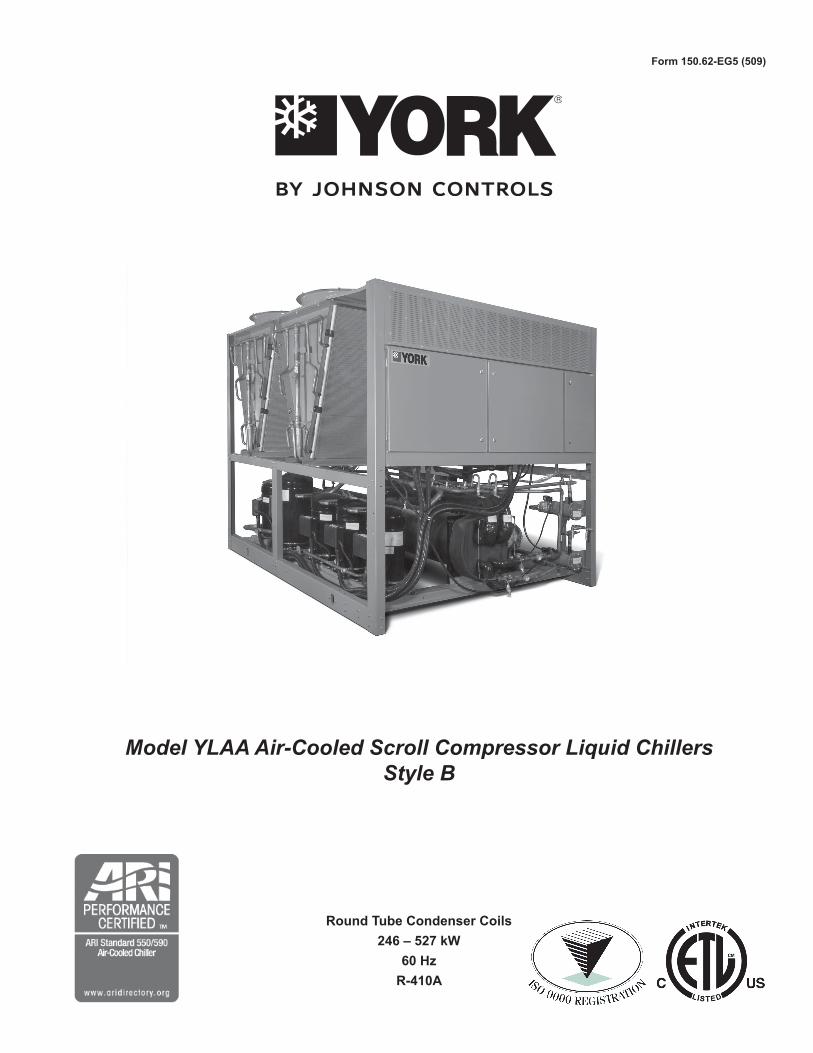
Design Parameters
NOTES:1. For leaving brine temperature below 40°F (4°C), contact your nearest Johnson Controls Office for application requirements.2. For leaving water temperature higher than 55°F (13°C), contact the nearest Johnson Controls Office for application guidelines. 3. The evaporator
is protected against freezing to -�0°F (-�9°C) with an electric heater as standard.�. For operation at temperatures below �0°F (-1°C), the optional Low Ambient Kit will need to be installed on the system (for YLAA00140080 models
only).
4. For operation at temperatures above 115°F (46°C), the optional High Ambient Kit will need to be installed on the system.
Nominal Evaporator Water Flow
Unit Designation
TemperatureWater Flow (gpm) MIN
Water Flow (gpm) MAX
Air On Condenser (°F)
Min (°F) Max (°F) Min Max
YLAA0070 40 55 60 �85 0 1�5
YLAA0080 40 55 100 �55 0 1�5
YLAA0090 40 55 140 6�5 0 1�5
YLAA0091 40 55 100 �85 0 1�5
YLAA0101 40 55 100 �85 0 1�5
YLAA0115 40 55 100 �85 0 1�5
YLAA0120 40 55 150 6�5 0 1�5
YLAA0135 40 55 1�0 6�5 0 1�5
YLAA0150 40 55 1�0 6�5 0 1�5
YLAA0155 40 55 150 6�5 0 1�5

FORM 150.62-EG5 (509)
11jOHNSON CONTROLS
Water Pressure DropYLAA Evaporator Pressure Drop (IP Units)
1.0
10.0
100.0
10 100 1000Water Flow Rate (GPM)
Pres
sure
Dro
p (ft
H2O
)
A
B
C
D
E
F
G
EVAPORATOR YLAA MODELSA 70SEB 80SEC 91HE,101HE, 115SED 120SE, 155SEE 90SEF 135SE, 150SE

1� jOHNSON CONTROLS
Selection Criteria and ProceduresGUIDE TO SELECTION
Capacity ratings for YORK YLAA Packaged Air-Cooled Liquid Chillers, shown on pages 18 through �� cover the majority of design applications for these units. For unusual applications or uses beyond the scope of this catalog, please consult your nearest Johnson Controls Office or representative.
SELECTION RULES
1. Ratings – Ratings may be interpolated, but must not be extrapolated. The Ratings given on pages 18 through �� and the DESIGN PARAMETERS given on page 10 indicate the limits of application for these chillers.
�. Evaporator Water – Ratings are based upon �.4 GPM per ton which is equal to a 10°F chilled water range and a 0.0001 fouling factor for the evaporator at sea level. Tables on pages 18 through �� give capacity, compressor kW required, evaporator GPM and unit EER.
�. Condenser – Ratings are given in terms of air on con-denser in degrees Fahrenheit.
4. Performance Data Correction Factors – Ratings are based on 0.0001 evaporator fouling factor, 10°F chilled water range and at sea level. For operation at different conditions, apply the appropriate correction factor from the following table.
FOULING FACTOR
ALTITUDE TEMP SPLIT TONS COMPR kW TONS COMPR kW
SEA LEVEL
8 0.994 0.999 0.991 0.998
10 1.000 1.000 0.993 0.999
12 1.005 1.001 0.999 0.999
14 1.008 1.002 1.005 1.000
2000 FT.
8 0.990 1.010 0.984 1.009
10 0.995 1.010 0.990 1.009
12 0.999 1.011 0.995 1.010
14 1.004 1.015 0.998 1.011
4000 FT.
8 0.983 1.021 0.977 1.020
10 0.989 1.024 0.983 1.021
12 0.994 1.025 0.988 1.024
14 0.997 1.026 0.993 1.025
6000 FT.
8 0.978 1.035 0.973 1.034
10 0.982 1.037 0.978 1.035
12 0.987 1.037 0.980 1.036
14 0.992 1.038 0.986 1.037
6. Ethylene Glycol Correction Factors – The following factors are to be applied to the standard ratings for units cooling ethylene glycol.
ETHYLENE GLYCOL
% WEIGHT TONS kW COMPR GPM°F/TON FREEZE PT
10 0.985 0.997 24.1 1.034 26
20 0.981 0.996 24.9 1.062 16
30 0.974 0.995 26.1 1.096 5
40 0.966 0.991 27.5 1.134 -10
50 0.957 0.989 29.1 1.172 -32
PRESS
DROP
7. Propylene Glycol Correction Factors – The following factors are to be applied to the standard ratings for units cooling propylene glycol.
PROPYLENE GLYCOL
% WEIGHT TONS kW COMPR GPM°F/TON FREEZE PT
10 0.983 0.996 24.2 1.048 27
20 0.974 0.995 24.4 1.086 19
30 0.961 0.990 25.1 1.134 8
40 0.946 0.980 26.0 1.186 -5
50 0.928 0.984 27.2 1.247 -25
PRESS
DROP
METHOD OF SELECTION
To select a johnson Controls - YLAA Packaged Air-Cooled Liquid Chiller, the following data must be known:
1. Design Capacity in tons refrigeration (TR).�. Entering and Leaving Liquid Temperatures.�. Outside ambient air temperature in degrees F. 4. GPM of chilled liquid.
Determine capacity requirements from the following formula:
EXAMPLE – WATER CHILLING1. GIVEN: Provide a capacity of 90 Tons at 4�°F
leaving water 10°F range, 0.0001FF, 80°F air on the condenser, at sea level and 60 Hz.
�. FIND: Unit Size Compressor kW Input�. From the Ratings on pages 18 - ��: SELECT: YLAA0090SE (English Units) 91.4 Tons 8� Compressor KW 1�.4 Unit EER4. Calculate Compressor kW at 50 Tons: kW = (90-91.4) x 80.7 = 80.7 kW
5. Calculate GPM:

FORM 150.62-EG5 (509)
1�jOHNSON CONTROLS
90 Tons x �4
GPM = �16 GPM
10°F Range6. From Page 10, read 10 ft of water evaporator
pressure drop for GPM:7. A YLAA0090 is suitable.
EXAMPLE – BRINE CHILLING
1. GIvEN: Provide a capacity of 80 tons cooling �0% by weight Ethylene Glycol from 50°F to 40°F, 0.000�5FF, 95°F air on the condenser, 60 Hz and 4000 altitude.
�. DETERMINE: Unit Size kW Input Ethylene Glycol GPM Evaporator Pressure
Drop�. See Ethylene Glycol correction factors, for �0%
by weight Ethylene Glycol. READ: .974 Tons factor .995 Compr. kW factor �6.1 Gal./°F/Tons factor4. See Performance Data Correction Factors for
0.000�5 fouling factor and 4000 ft. altitude. READ: .98� Tons factor 1.0�1 kW factor
5. From RATINGS on pages 18 - ��: SELECT: YLAA0090 (English Units) 91.4 Tons 8�.0 Compressor kW
6. Determine YLAA0090 brine cooling capacity and Compressor kW requirement:
A. Tons = 91.4 x .974 x .98� = 87.51 B. Compr. kW = 8�.0 x .995 x 1.0�1 = 8�.�
Determine average full load Compressor kW atDetermine average full load Compressor kW at 80 tons: (80/87.51) x 8�.� = 76.15kW8. Determine Ethylene Glycol GPM: Tons x Gal. °F/min/Ton factor GPM = Range 80.0 x �6.1
GPM = 10 GPM = �08.89. Determine Evaporator Pressure Drop:
A. See Ethylene Glycol correction factors for �0% by weight Ethylene Glycol.
READ: 1.096 Pressure Drop Factor B. See pages 18-19 at 88.7 GPM for the YLAA0090.
READ: 6.8 Ft. H�O Pressure Drop C. Evaporator Pressure Drop = 6.8 x 1.096 or 7.5
Ft.H�O10. YLAA0090 is suitable.
14 jOHNSON CONTROLS
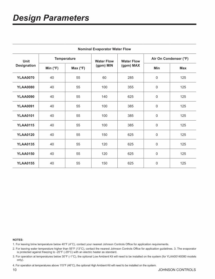
PUMP SELECTION
Multiple pump sizes are available for each YLAA model providing the ability to closely match the system require-ments. Within the YORKworks CE chiller selection pro-gram is an integral pump selection program that can be used for a quick and easy pump selection. Please contact your local johnson Controls sales rep for assistance with this selection program. If this program is not available or if a manual selection is desired, the following steps can be followed to make a pump selection for the hydro kit option.
1. Determine whether a single pump or dual pump (standby) option is required. For this example, single pump hydro kits will be used.
2. Determine the required flow (GPM). This value will
be calculated with the chiller selection. Pump design flow must be within the limits of the chiller.
ex. 100 Ton Chiller: ��5 gpm (YLAA 0101HE) single pump option
�. Calculate the external system pressure loss (ft) for all piping and components external to the chiller.
ex. 45 ft
4. Determine the internal pressure loss to the chiller (ft) due to the evaporator from the Water Pressure Drop charts. Combine this with the external system pres-sure loss (ft) to determine the preliminary pressure loss.
ex. Internal Pressure Loss due to evapora tor:1� ft (from chart on page 11)
Preliminary pressure loss: 45 ft (exter nal) + 1� ft (evaporator) = 57 ft
5. Review the available hydro kit options for the YLAA model (See Table 1) selected using the Hydro Kit by Models Chart. Use the flow and head calculated in steps � and 4 to select a preliminary design point. If the preliminary design point does not fall directly on the curve, select the next step larger size of impeller.
ex. Preliminary design point: ��5 gpm/57 ft
Preliminary selection: Hydro Kit B/�x�x10@ 1740 rpm; 9.00 in impeller diameter with 7.5Hp motor.
6. Using the Hydro Kit pressure loss charts found on page 16-17, determine the internal pressure loss to the chiller due to the hydro kit piping for the selected Hydro Kit. Add this to the preliminary pressure loss (from step 4) to determine the total pressure loss:
ex. For Hydro Kit B on YLAA0101 unit, the hydro kit pressure loss is 15 ft.
Total pressure loss = 57 ft + 15 ft = 7� ft
7. Check to see if the Hydro-Kit selection is valid. Us-ing the total pressure loss (from step 6), plot the flow (GPM) and the total pressure loss on the hydro kit selected in step 5. If the pump selection is no longer adequate, re-select a hydro kit and go back to step 6. (Note: if a design point does not fall directly on the curve, one can select the next step larger size of impeller and use the circuit balancing valve to adjust the system head requirements and correct for small variations from the selected pump curve.) If the pump selection is satisfactory, proceed to step 8.
ex. Total Pressure Loss = 7�ft. with GPM = ��5Selection is still valid for a Hydro-Kit B (�x�x10, 1800rpm, 9” impeller @ 7.5Hp)
8. The pump efficiency can be read from the pump curve using the dashed efficiency lines labeled as a percentage.
ex. Efficiency: 68 % (from pump curve)
9. The pump is selected ex. Hydro Kit B at 68%
10. The pump NPSHr required can also be read from the pump curves. When selecting a pump one must make sure that the system designed NPSHa available is greater than the NPSHr required by the pump plus the fluid vapor pressure.
ex. NPSHr = 6 ft (From Pump Curve for Hydro Kit B)
NPSHa = �0 ft (From System Design - Figure �)
VP = 0.4 ft (Water at 50ºF) NPSHr + VP < NPSHa 6 ft + 0.4 ft < �0 ft
If the system flow or pressure exceeds that of the hydro kit pump curves provided, an integral hydro kit is not available for your application and a separate pump must be provided.
Pump Selection Criteria

FORM 150.62-EG5 (509)
15jOHNSON CONTROLS
TABLE1 – PUMP SELECTION INFORMATION
KIT SERIES KIT TYPE PUMP SIZE PUMP HP MOTOR RPM MODELS WHERE USED
A 4380 Single 3X3X8 5 1800 7.5 70,80,90,91
B 4380 Single 3X3X10 7.5 1800 9 70,80,90,91,101
C 4380 Single 3X3X10 10 1800 10 70,80,115,120,135
D 4380 Single 3X3X6 15 3600 5.9 70,80,90,91,101,115,120,135
E 4380 Single 3X3X8 20 3600 6.3 90,91,101,115,120,135
F 4380 Single 3X3X8 7.5 1800 8 101,115,120,135
G 4380 Single 4X4X8 10 1800 7.6 150,155
H 4380 Single 4X4X6 10 3600 4.9 150,155
I 4380 Single 4X4X6 15 3600 5.5 150,155
J 4380 Single 4X4X6 20 3600 6 150,155
K 4382 Dual 4X4X8 7.5 1800 7.9 70,80,90,91,101,115,120,135
L 4382 Dual 4X4X6 10 3600 5.3 70,80,90,91,101,115,150,155
M 4382 Dual 4X4X6 15 3600 5.6 70,80,90,91,120,135,150,155
N 4382 Dual 3X3X8 15 3600 6.6 70,80,90,91,
O 4382 Dual 4X4X6 15 3600 5.9 101,115,120,165
P 4382 Dual 3X3X8 20 3600 7.2 101,115,120
R 4382 Dual 4X4X8 20 3600 6.3 135,150,155
IMPELLER DIA
(IN)
16 jOHNSON CONTROLS
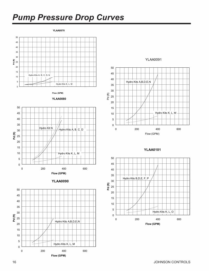
Pump Pressure Drop CurvesYLAA0070
0
5
10
15
20
25
30
35
40
45
50
Flow (GPM)
Pd(ft
)
Hydro Kits A, B, C, D, N
Hydro Kits K, L, M
YLAA0080
0
5
10
15
20
25
30
35
40
45
50
0 200 400 600
Flow (GPM)
Pd(ft
)
Hydro Kit N
Hydro Kits K, L, M
Hydro Kits A, B, C, D
YLAA0090
0
5
10
15
20
25
30
35
40
45
50
0 200 400 600
Flow (GPM)
Pd(ft
)
Hydro Kits K, L, M
Hydro Kits A,B,D,E,N
YLAA0091
0
5
10
15
20
25
30
35
40
45
50
0 200 400 600
Flow (GPM)
Pd
(ft)
Hydro Kits K, L, M
Hydro Kits A,B,D,E,N
YLAA0101
0
5
10
15
20
25
30
35
40
45
50
0 200 400 600
Flow (GPM)
Pd(ft
)
Hydro Kits B,D,E, F, P
Hydro Kits K, L, O

FORM 150.62-EG5 (509)
17jOHNSON CONTROLS
YLAA0115
0
5
10
15
20
25
30
35
40
45
50
0 200 400 600
Flow (GPM)
Pd(ft
)
Hydro Kits K, L, O
Hydro Kits C,D,E, F
Hydro Kit P
YLAA0120
0
5
10
15
20
25
30
35
40
45
50
0 200 400 600
Flow (GPM)
Pd(ft
)
Hydro Kit P
Hydro Kits C,D,E, F, K, M, O
YLAA0135
0
5
10
15
20
25
30
35
40
45
50
0 200 400 600
Flow (GPM)
Pd(ft
)
Hydro Kit K,M,O,R
Hydro Kits C,D,E, F
YLAA0150
0
5
10
15
20
25
30
35
40
45
50
0 200 400 600
Flow (GPM)
Pd(ft
)Hydro Kits G,H,I,J,L,M,R
YLAA0155
0
5
10
15
20
25
30
35
40
45
50
0 100 200 300 400 500 600 700
Flow (GPM)
Pd(ft
)
Hydro Kits G,H,I,J,L,M,R

18 jOHNSON CONTROLS
Single Pump Curves
Kit A & F Kit E
Kit GKit B & C
Kit N, I, & JKit D

FORM 150.62-EG5 (509)
19jOHNSON CONTROLS
Dual Pump Curves
Kit L, M, & O Kit R
Kit N & PKit K

�0 jOHNSON CONTROLS
Ratings - 60 Hz
NOTES:1. kW = Compressor Input Power�. EER = Chiller EER (includes power from compressors, fans, and the control panels 0.8 kW)�. LCWT = Leaving Chilled Water Temperature4. Ratings are based upon �.4 GPM evaporator water per ton and 0.0001 fouling factor5. Rated in accordance with ARI Standard 550/5906. The shaded points are certified in accordance with ARI Standard 550/590-98
MODEL: YLAA0070ZE IPLV: 15.7 AIR TEMPERATURE ON - CONDENSER (°F)
LCHWT(°F)
75.0 80.0 85.0 90.0 95.0 100.0TONS KW EER TONS KW EER TONS KW EER TONS KW EER TONS KW EER TONS KW EER
40.0 74.7 61.9 13.1 72.8 65.2 12.1 70.9 68.8 11.3 68.8 72.7 10.4 66.8 76.8 9.6 64.3 80.8 8.842.0 77.1 62.5 13.4 75.1 65.9 12.4 73.1 69.5 11.5 71.0 73.3 10.6 68.9 77.4 9.8 66.3 81.5 9.044.0 79.5 63.2 13.6 77.5 66.5 12.7 75.4 70.1 11.8 73.3 74.0 10.9 71.1 78.1 10.1 68.4 82.1 9.245.0 80.7 63.5 13.8 78.7 66.8 12.8 76.6 70.5 11.9 74.4 74.4 11.0 72.2 78.5 10.2 69.5 82.5 9.346.0 82.0 63.8 13.9 79.9 67.2 13.0 77.8 70.8 12.0 75.6 74.7 11.1 73.3 78.8 10.3 70.6 82.8 9.548.0 84.5 64.5 14.2 82.3 67.9 13.2 80.2 71.5 12.3 77.9 75.4 11.4 75.5 79.5 10.5 72.7 83.5 9.750.0 87.1 65.2 14.5 84.9 68.6 13.5 82.6 72.2 12.5 80.2 76.1 11.6 77.8 80.2 10.7 74.9 84.3 9.9
MODEL: YLAA0080ZE IPLV: 15.0 AIR TEMPERATURE ON - CONDENSER (°F)
LCHWT(°F)
75.0 80.0 85.0 90.0 95.0 100.0TONS KW EER TONS KW EER TONS KW EER TONS KW EER TONS KW EER TONS KW EER
40.0 80.3 69.1 12.7 78.2 72.9 11.8 76.0 77.0 10.9 73.8 81.4 10.0 71.5 86.1 9.2 68.7 90.8 8.542.0 82.9 69.8 13.0 80.7 73.6 12.1 78.5 77.7 11.1 76.1 82.2 10.3 73.8 86.9 9.5 70.9 91.5 8.744.0 85.5 70.6 13.3 83.3 74.4 12.3 81.0 78.5 11.4 78.6 83.0 10.5 76.1 87.7 9.7 73.2 92.3 8.945.0 86.8 71.0 13.4 84.5 74.8 12.4 82.2 78.9 11.5 79.8 83.4 10.6 77.3 88.1 9.8 74.4 92.7 9.046.0 88.2 71.4 13.6 85.9 75.2 12.6 83.5 79.3 11.6 81.0 83.8 10.7 78.5 88.5 9.9 75.5 93.1 9.148.0 90.9 72.2 13.8 88.5 76.0 12.8 86.0 80.2 11.9 83.5 84.6 11.0 81.0 89.3 10.1 77.9 93.9 9.350.0 93.7 73.0 14.1 91.2 76.9 13.1 88.7 81.0 12.1 86.1 85.4 11.2 83.5 90.1 10.3 80.3 94.8 9.5
MODEL: YLAA0090ZE IPLV: 14.9 AIR TEMPERATURE ON - CONDENSER (°F)
LCHWT(°F)
75.0 80.0 85.0 90.0 95.0 100.0TONS KW EER TONS KW EER TONS KW EER TONS KW EER TONS KW EER TONS KW EER
40.0 89.8 77.6 12.8 87.3 81.8 11.8 84.7 86.3 10.9 82.0 91.2 10.0 79.2 96.3 9.2 76.0 101.4 8.442.0 92.7 78.5 13.1 90.1 82.7 12.1 87.5 87.2 11.2 84.7 92.1 10.3 81.9 97.3 9.5 78.6 102.4 8.644.0 95.6 79.4 13.3 93.0 83.7 12.3 90.3 88.2 11.4 87.5 93.1 10.5 84.6 98.2 9.7 81.2 103.3 8.945.0 97.1 79.9 13.4 94.4 84.2 12.5 91.7 88.7 11.5 88.9 93.6 10.6 86.0 98.7 9.8 82.5 103.9 9.046.0 98.6 80.4 13.6 95.9 84.7 12.6 93.1 89.3 11.6 90.3 94.1 10.7 87.4 99.3 9.9 83.9 104.4 9.148.0 101.6 81.5 13.8 98.8 85.7 12.8 95.9 90.3 11.9 93.1 95.2 11.0 90.1 100.3 10.1 86.5 105.4 9.350.0 104.7 82.5 14.1 101.8 86.8 13.1 98.9 91.4 12.1 95.9 96.2 11.2 92.9 101.4 10.3 89.2 106.5 9.5

FORM 150.62-EG5 (509)
�1jOHNSON CONTROLS
NOTES:1. kW = Compressor Input Power�. EER = Chiller EER (includes power from compressors, fans, and the control panels 0.8 kW)�. LCWT = Leaving Chilled Water Temperature4. Ratings are based upon �.4 GPM evaporator water per ton and 0.0001 fouling factor5. Rated in accordance with ARI Standard 550/5906. The shaded points are certified in accordance with ARI Standard 550/590-98
MODEL: YLAA0070ZE IPLV: 15.7 AIR TEMPERATURE ON - CONDENSER (°F)
LCHWT(°F)
105.0 110.0 115.0TONS KW EER TONS KW EER TONS KW EER
40.0 61.7 85.0 8.1 59.0 89.5 7.4 56.3 94.1 6.742.0 63.7 85.7 8.3 60.9 90.1 7.5 58.1 94.8 6.944.0 65.7 86.4 8.5 62.9 90.8 7.7 60.0 95.5 7.045.0 66.7 86.7 8.6 63.9 91.2 7.8 60.9 95.9 7.146.0 67.7 87.1 8.7 64.9 91.6 7.9 61.9 96.2 7.248.0 69.8 87.8 8.9 66.9 92.3 8.1 63.8 97.0 7.450.0 72.0 88.5 9.1 68.9 93.0 8.3 65.8 97.7 7.6
MODEL: YLAA0080ZE IPLV: 15.0 AIR TEMPERATURE ON - CONDENSER (°F)
LCHWT(°F)
105.0 110.0 115.0TONS KW EER TONS KW EER TONS KW EER
40.0 65.9 95.6 7.7 63.0 100.8 7.0 51.4 83.4 6.842.0 68.0 96.4 7.9 65.1 101.6 7.2 53.2 84.0 7.044.0 70.2 97.2 8.1 67.2 102.4 7.4 55.0 84.6 7.245.0 71.4 97.6 8.2 68.3 102.8 7.5 55.9 84.9 7.346.0 72.5 98.0 8.3 69.3 103.2 7.6 56.8 85.2 7.448.0 74.7 98.9 8.5 71.5 104.0 7.7 58.7 85.8 7.650.0 77.1 99.7 8.7 73.7 104.9 7.9 60.6 86.4 7.8
MODEL: YLAA0090ZE IPLV: 14.9 AIR TEMPERATURE ON - CONDENSER (°F)
LCHWT(°F)
105.0 110.0 115.0TONS KW EER TONS KW EER TONS KW EER
40.0 72.7 106.7 7.7 69.4 112.4 7 48.1 72.8 7.342.0 75.2 107.7 7.9 71.8 113.3 7.2 49.8 73.3 7.544.0 77.7 108.7 8.1 74.2 114.4 7.4 51.6 73.8 7.745.0 79 109.2 8.2 75.4 114.9 7.4 52.5 74 7.846.0 80.3 109.8 8.3 76.6 115.4 7.5 53.4 74.3 7.948.0 82.9 110.8 8.5 79.1 116.5 7.7 55.2 74.9 8.150.0 85.5 111.9 8.6 70.9 94.6 8.4 57.1 75.4 8.3

�� jOHNSON CONTROLS
Ratings - 60 Hz – continued
NOTES:1. kW = Compressor Input Power�. EER = Chiller EER (includes power from compressors, fans, and the control panels 0.8 kW)�. LCWT = Leaving Chilled Water Temperature4. Ratings are based upon �.4 GPM evaporator water per ton and 0.0001 fouling factor5. Rated in accordance with ARI Standard 550/5906. The shaded points are certified in accordance with ARI Standard 550/590-98
MODEL: YLAA0091YE IPLV: 14.6 AIR TEMPERATURE ON - CONDENSER (°F)
LCHWT(°F)
75.0 80.0 85.0 90.0 95.0 100.0TONS KW EER TONS KW EER TONS KW EER TONS KW EER TONS KW EER TONS KW EER
40.0 91.3 70.5 13.6 88.9 74.3 12.7 86.5 78.4 11.7 84.1 82.7 10.9 81.6 87.4 10.0 78.5 92.1 9.242.0 94.3 71.2 13.9 91.9 74.9 13.0 89.5 79.0 12.1 86.9 83.4 11.2 84.3 88.1 10.3 81.2 92.8 9.544.0 97.4 71.9 14.3 95.0 75.6 13.3 92.4 79.7 12.4 89.8 84.1 11.5 87.1 88.8 10.6 83.9 93.5 9.745.0 99.0 72.3 14.4 96.5 76.0 13.5 93.9 80.0 12.5 91.3 84.4 11.6 88.6 89.1 10.7 85.3 93.8 9.846.0 100.6 72.6 14.6 98.0 76.4 13.6 95.4 80.4 12.7 92.8 84.8 11.7 90.0 89.5 10.8 86.7 94.2 10.048.0 103.8 73.4 14.9 101.2 77.1 13.9 98.5 81.2 13.0 95.7 85.5 12.0 92.9 90.2 11.1 89.5 95.0 10.250.0 107.1 74.2 15.2 104.4 77.9 14.2 101.6 81.9 13.3 98.8 86.3 12.3 95.8 91.0 11.4 92.3 95.7 10.5
MODEL: YLAA0101YE IPLV: 14.9 AIR TEMPERATURE ON - CONDENSER (°F)
LCHWT(°F)
75.0 80.0 85.0 90.0 95.0 100.0TONS KW EER TONS KW EER TONS KW EER TONS KW EER TONS KW EER TONS KW EER
40.0 102.2 84.3 13.0 99.5 88.9 12.1 96.8 93.9 11.2 94.0 99.2 10.3 91.2 104.9 9.5 87.7 110.6 8.742.0 105.5 85.1 13.3 102.8 89.7 12.4 100.0 94.7 11.5 97.1 100.1 10.6 94.2 105.8 9.8 90.6 111.4 9.044.0 108.9 86.0 13.6 106.1 90.6 12.7 103.3 95.6 11.7 100.3 100.9 10.8 97.3 106.6 10.0 93.6 112.3 9.245.0 110.7 86.4 13.8 107.8 91.1 12.8 104.9 96.0 11.9 101.9 101.4 11.0 98.8 107.1 10.1 95.1 112.8 9.346.0 112.4 86.9 13.9 109.5 91.5 12.9 106.6 96.5 12.0 103.5 101.8 11.1 100.4 107.6 10.2 96.7 113.3 9.448.0 116.0 87.8 14.2 113.0 92.5 13.2 110.0 97.4 12.3 106.8 102.8 11.4 103.6 108.5 10.5 99.7 114.2 9.650.0 119.6 88.8 14.5 116.5 93.4 13.5 113.3 98.4 12.5 110.2 103.8 11.6 106.9 109.5 10.7 102.9 115.2 9.9
MODEL: YLAA0115ZE IPLV: 14.3 AIR TEMPERATURE ON - CONDENSER (°F)
LCHWT(°F)
75.0 80.0 85.0 90.0 95.0 100.0TONS KW EER TONS KW EER TONS KW EER TONS KW EER TONS KW EER TONS KW EER
40.0 118.5 104.1 12.5 115.5 109.6 11.6 112.3 115.5 10.7 109.0 121.9 9.9 105.6 128.6 9.1 101.5 135.2 8.442.0 122.4 105.2 12.7 119.2 110.7 11.8 115.9 116.7 11.0 112.5 123.1 10.1 109.0 129.8 9.4 104.8 136.5 8.644.0 126.3 106.4 13.0 123.0 112.0 12.1 119.6 117.9 11.2 116.1 124.3 10.4 112.5 131.1 9.6 108.2 137.7 8.845.0 128.2 107.0 13.1 124.9 112.6 12.2 121.5 118.5 11.3 117.9 124.9 10.5 114.2 131.7 9.7 109.9 138.3 8.946.0 130.2 107.6 13.3 126.8 113.2 12.3 123.3 119.2 11.5 119.7 125.6 10.6 116.0 132.3 9.8 111.6 139.0 9.048.0 134.2 108.8 13.5 130.7 114.5 12.6 127.1 120.4 11.7 123.4 126.9 10.8 119.6 133.6 10.0 115.1 140.3 9.250.0 138.2 110.1 13.8 134.6 115.8 12.8 130.9 121.8 11.9 127.1 128.2 11.0 123.2 135.0 10.2 118.6 141.7 9.4

FORM 150.62-EG5 (509)
��jOHNSON CONTROLS
NOTES:1. kW = Compressor Input Power�. EER = Chiller EER (includes power from compressors, fans, and the control panels 0.8 kW)�. LCWT = Leaving Chilled Water Temperature4. Ratings are based upon �.4 GPM evaporator water per ton and 0.0001 fouling factor5. Rated in accordance with ARI Standard 550/5906. The shaded points are certified in accordance with ARI Standard 550/590-98
MODEL: YLAA0091YE IPLV: 14.6 AIR TEMPERATURE ON - CONDENSER (°F)
LCHWT(°F)
105.0 110.0 115.0TONS KW EER TONS KW EER TONS KW EER
40.0 75.4 97.1 8.4 72.2 102.3 7.7 68.9 107.7 742.0 78 97.7 8.7 74.7 102.9 7.9 71.3 108.4 7.244.0 80.6 98.4 8.9 77.2 103.7 8.1 73.8 109.2 7.445.0 81.9 98.8 9 78.5 104 8.3 75 109.5 7.546.0 83.3 99.2 9.1 79.8 104.4 8.4 76.3 109.9 7.648.0 86 99.9 9.4 82.4 105.2 8.6 78.8 110.7 7.850.0 88.7 100.7 9.6 85.1 105.9 8.8 81.4 111.5 8
MODEL: YLAA0101YE IPLV: 14.9 AIR TEMPERATURE ON - CONDENSER (°F)
LCHWT(°F)
105.0 110.0 115.0TONS KW EER TONS KW EER TONS KW EER
40.0 84.2 116.5 8 80.6 122.8 7.3 68 107.3 742.0 87 117.4 8.2 83.3 123.7 7.5 70.4 108 7.244.0 89.9 118.3 8.4 86.1 124.6 7.7 72.8 108.7 7.445.0 91.4 118.8 8.5 87.5 125.1 7.8 74.1 109 7.546.0 92.8 119.2 8.6 88.9 125.5 7.9 75.3 109.4 7.648.0 95.8 120.2 8.8 91.8 126.5 8.1 55.5 69.4 8.450.0 98.8 121.2 9 94.7 127.5 8.3 57.5 69.8 8.6
MODEL: YLAA0115ZE IPLV: 14.3 AIR TEMPERATURE ON - CONDENSER (°F)
LCHWT(°F)
105.0 110.0 115.0TONS KW EER TONS KW EER TONS KW EER
40.0 97.4 142.2 7.7 93.1 149.5 7 88.7 157.1 6.442.0 100.6 143.4 7.9 96.2 150.8 7.2 91.7 158.4 6.544.0 103.8 144.7 8 99.3 152 7.4 94.7 159.7 6.745.0 105.4 145.3 8.1 100.9 152.7 7.4 96.2 160.3 6.846.0 107.1 146 8.2 102.5 153.3 7.5 56.7 71.3 8.448.0 110.4 147.3 8.4 105.7 154.7 7.7 58.7 71.8 8.650.0 113.8 148.7 8.6 108.9 156.1 7.9 60.7 72.3 8.8

�4 jOHNSON CONTROLS
Ratings - 60 Hz – continued
NOTES:1. kW = Compressor Input Power�. EER = Chiller EER (includes power from compressors, fans, and the control panels 0.8 kW)�. LCWT = Leaving Chilled Water Temperature4. Ratings are based upon �.4 GPM evaporator water per ton and 0.0001 fouling factor5. Rated in accordance with ARI Standard 550/5906. The shaded points are certified in accordance with ARI Standard 550/590-98
MODEL: YLAA0120ZE IPLV: 14.5 AIR TEMPERATURE ON - CONDENSER (°F)
LCHWT(°F)
75.0 80.0 85.0 90.0 95.0 100.0TONS KW EER TONS KW EER TONS KW EER TONS KW EER TONS KW EER TONS KW EER
40.0 125.3 107.4 12.8 121.9 113.1 11.9 118.4 119.0 11.0 114.8 125.4 10.2 111.0 132.2 9.4 106.6 138.9 8.642.0 129.4 108.7 13.1 125.8 114.3 12.1 122.2 120.3 11.3 118.5 126.8 10.4 114.7 133.5 9.6 110.1 140.2 8.844.0 133.5 110.0 13.3 129.8 115.6 12.4 126.1 121.6 11.5 122.3 128.1 10.6 118.3 134.9 9.8 113.7 141.6 9.045.0 135.6 110.6 13.5 131.9 116.3 12.5 128.1 122.3 11.6 124.2 128.8 10.7 120.2 135.6 9.9 115.5 142.3 9.146.0 137.7 111.3 13.6 133.9 117.0 12.6 130.1 123.0 11.7 126.1 129.5 10.8 122.1 136.3 10.0 117.3 143.0 9.248.0 141.9 112.7 13.9 138.0 118.4 12.9 134.1 124.4 12.0 130.0 130.9 11.1 125.9 137.7 10.2 120.3 144.2 9.450.0 146.2 114.1 14.1 142.2 119.8 13.1 138.1 126.0 12.2 133.9 132.4 11.3 129.7 139.2 10.4 124.6 145.9 9.6
MODEL: YLAA0135ZE IPLV: 14.9 AIR TEMPERATURE ON - CONDENSER (°F)
LCHWT(°F)
75.0 80.0 85.0 90.0 95.0 100.0TONS KW EER TONS KW EER TONS KW EER TONS KW EER TONS KW EER TONS KW EER
40.0 132.3 112.9 12.6 128.8 119.0 11.7 125.3 125.4 10.8 121.6 132.3 10.0 117.9 139.7 9.2 113.4 146.9 8.542.0 136.6 114.1 12.9 133.1 120.2 12.0 129.4 126.6 11.1 125.7 133.5 10.3 121.8 140.9 9.5 117.2 148.1 8.744.0 141.0 115.4 13.1 137.4 121.4 12.2 133.6 127.8 11.4 129.7 134.8 10.5 125.8 142.1 9.7 121.0 149.4 8.945.0 143.2 116.0 13.3 139.5 122.0 12.4 135.7 128.5 11.5 131.8 135.4 10.6 127.8 142.8 9.8 123.0 150.0 9.046.0 145.5 116.6 13.4 141.7 122.7 12.5 137.9 129.1 11.6 133.9 136.1 10.7 129.8 143.4 9.9 124.9 150.7 9.148.0 150.0 117.9 13.7 146.1 124.0 12.8 142.2 130.5 11.9 138.1 137.4 11.0 133.9 144.8 10.2 128.8 152.1 9.350.0 154.6 119.3 14.0 150.6 125.4 13.0 146.5 131.9 12.1 142.3 138.8 11.2 138.0 146.1 10.4 132.8 153.5 9.6
MODEL: YLAA0150ZE IPLV: 14.9 AIR TEMPERATURE ON - CONDENSER (°F)
LCHWT(°F)
75.0 80.0 85.0 90.0 95.0 100.0TONS KW EER TONS KW EER TONS KW EER TONS KW EER TONS KW EER TONS KW EER
40.0 146.0 127.7 12.4 142.2 134.5 11.5 138.3 141.8 10.7 134.3 149.6 9.9 130.1 157.8 9.1 125.1 166.0 8.442.0 150.7 129.0 12.7 146.8 135.9 11.8 142.8 143.1 10.9 138.6 151.0 10.1 134.4 159.2 9.3 129.2 167.4 8.644.0 155.5 130.4 13.0 151.5 137.3 12.1 147.4 144.6 11.2 143.1 152.4 10.3 138.7 160.7 9.6 133.4 168.9 8.845.0 158.0 131.1 13.1 153.9 138.0 12.2 149.7 145.3 11.3 145.3 153.2 10.5 140.9 161.5 9.7 135.5 169.7 8.946.0 160.4 131.8 13.2 156.2 138.8 12.3 152.0 146.1 11.4 147.6 153.9 10.6 143.0 162.2 9.8 137.6 170.5 9.048.0 165.3 133.3 13.5 161.1 140.3 12.6 156.7 147.6 11.7 152.1 155.5 10.8 147.5 163.8 10.0 141.9 172.0 9.250.0 170.3 134.9 13.8 165.9 141.8 12.8 161.4 149.3 11.9 156.8 157.1 11.0 152.0 165.4 10.2 146.2 173.6 9.4

FORM 150.62-EG5 (509)
�5jOHNSON CONTROLS
NOTES:1. kW = Compressor Input Power�. EER = Chiller EER (includes power from compressors, fans, and the control panels 0.8 kW)�. LCWT = Leaving Chilled Water Temperature4. Ratings are based upon �.4 GPM evaporator water per ton and 0.0001 fouling factor5. Rated in accordance with ARI Standard 550/5906. The shaded points are certified in accordance with ARI Standard 550/590-98
MODEL: YLAA0120ZE IPLV: 14.5 AIR TEMPERATURE ON - CONDENSER (°F)
LCHWT(°F)
105.0 110.0 115.0TONS KW EER TONS KW EER TONS KW EER
40.0 102.1 145.9 7.9 97.4 153.2 7.2 92.7 160.9 6.542.0 105.5 147.3 8 100.7 154.6 7.3 74.8 116.8 7.144.0 108.9 148.6 8.2 104.1 156 7.5 56.1 72 8.245.0 110.7 149.3 8.3 105.7 156.7 7.6 57.1 72.3 8.346.0 112.4 150.1 8.4 107.4 157.4 7.7 58.1 72.5 8.448.0 115.9 151.5 8.6 110.8 158.9 7.9 60.1 73 8.750.0 119.5 153 8.8 114.2 160.4 8 62.2 73.5 8.9
MODEL: YLAA0135ZE IPLV: 14.9 AIR TEMPERATURE ON - CONDENSER (°F)
LCHWT(°F)
105.0 110.0 115.0TONS KW EER TONS KW EER TONS KW EER
40.0 108.8 154.6 7.8 104.1 162.6 7.1 83.3 125.2 7.242.0 112.4 155.8 8 107.6 163.9 7.3 86.2 126 7.444.0 116.1 157.1 8.2 111.2 165.2 7.5 89.2 126.8 7.645.0 118 157.7 8.3 113 165.8 7.6 90.7 127.2 7.746.0 119.9 158.4 8.4 114.8 166.5 7.7 92.2 127.7 7.848.0 123.7 159.8 8.6 118.5 167.9 7.8 95.3 128.5 8.150.0 127.6 161.2 8.8 122.2 169.3 8 98.4 129.4 8.3
MODEL: YLAA0150ZE IPLV: 14.9 AIR TEMPERATURE ON - CONDENSER (°F)
LCHWT(°F)
105.0 110.0 115.0TONS KW EER TONS KW EER TONS KW EER
40.0 120 174.6 7.7 114.8 183.6 7 93.4 147.1 742.0 124 176 7.9 118.7 185.1 7.2 96.6 148.1 7.244.0 128 177.5 8 122.5 186.6 7.4 99.9 149.2 7.445.0 130.1 178.3 8.1 124.5 187.4 7.4 101.6 149.7 7.546.0 132.1 179.1 8.2 126.5 188.1 7.5 103.2 150.3 7.648.0 136.2 180.7 8.4 130.4 189.7 7.7 106.6 151.4 7.850.0 140.4 182.3 8.6 134.5 191.4 7.9 110 152.5 8

�6 jOHNSON CONTROLS
MODEL: YLAA0155ZE IPLV: 14.8 AIR TEMPERATURE ON - CONDENSER (°F)
LCHWT(°F)
75.0 80.0 85.0 90.0 95.0 100.0TONS KW EER TONS KW EER TONS KW EER TONS KW EER TONS KW EER TONS KW EER
40.0 149.4 130.1 12.5 145.4 137.0 11.6 141.4 144.3 10.8 137.1 152.2 9.9 132.8 160.5 9.2 127.6 168.7 8.442.0 154.3 131.6 12.8 150.2 138.5 11.9 146.0 145.8 11.0 141.6 153.7 10.2 137.1 162.0 9.4 131.8 170.3 8.644.0 159.2 133.1 13.0 154.9 140.0 12.1 150.6 147.3 11.2 146.1 155.2 10.4 141.6 163.5 9.6 136.1 171.8 8.845.0 161.6 133.8 13.2 157.4 140.8 12.2 153.0 148.1 11.4 148.4 156.0 10.5 143.8 164.3 9.7 138.2 172.6 8.946.0 164.1 134.6 13.3 159.8 141.5 12.4 155.4 148.9 11.5 150.7 156.8 10.6 146.0 165.1 9.8 140.4 173.4 9.048.0 169.2 136.1 13.6 164.6 143.1 12.6 160.1 150.6 11.7 155.4 158.4 10.9 150.6 166.8 10.0 144.8 175.1 9.250.0 174.3 137.8 13.8 169.7 144.8 12.9 164.9 152.3 11.9 160.1 160.1 11.1 155.1 168.5 10.2 149.2 176.8 9.4
Ratings - 60 Hz – continued
NOTES:1. kW = Compressor Input Power�. EER = Chiller EER (includes power from compressors, fans, and the control panels 0.8 kW)�. LCWT = Leaving Chilled Water Temperature4. Ratings are based upon �.4 GPM evaporator water per ton and 0.0001 fouling factor5. Rated in accordance with ARI Standard 550/5906. The shaded points are certified in accordance with ARI Standard 550/590-98

FORM 150.62-EG5 (509)
�7jOHNSON CONTROLS
MODEL: YLAA0155ZE IPLV: 14.8 AIR TEMPERATURE ON - CONDENSER (°F)
LCHWT(°F)
105.0 110.0 115.0TONS KW EER TONS KW EER TONS KW EER
40.0 122.3 177.4 7.7 116.9 186.4 7 94.5 149 742.0 126.4 178.9 7.9 120.8 188 7.2 97.8 150.1 7.244.0 130.5 180.5 8.1 124.8 189.6 7.4 101.2 151.2 7.445.0 132.6 181.3 8.2 126.8 190.4 7.5 102.9 151.8 7.546.0 134.7 182.1 8.3 128.8 191.2 7.6 104.4 152.3 7.648.0 138.9 183.8 8.4 132.9 192.9 7.7 108 153.5 7.850.0 143.1 185.5 8.6 116.7 147.3 8.7 111.5 154.7 8
NOTES:1. kW = Compressor Input Power�. EER = Chiller EER (includes power from compressors, fans, and the control panels 0.8 kW)�. LCWT = Leaving Chilled Water Temperature4. Ratings are based upon �.4 GPM evaporator water per ton and 0.0001 fouling factor5. Rated in accordance with ARI Standard 550/5906. The shaded points are certified in accordance with ARI Standard 550/590-98

�8 jOHNSON CONTROLS
Part Load Ratings – Standard Efficiency
YLAA0070SE
% DISPL AMBIENT °F TONS COMP KW EER
100.0 95.0 66.0 75.8 9.683.3 88.3 58.6 56.8 11.166.7 80.9 50.5 39.9 13.050.0 70.8 39.4 26.6 14.933.3 60.0 27.4 15.5 17.516.7 55.0 13.7 7.3 18.3
IPLV: 15.1 EER
YLAA0080SE
% DISPL AMBIENT °F TONS COMP KW EER
100.0 95.0 72.8 84.2 9.683.6 88.4 64.8 64.2 11.066.7 80.6 55.3 43.5 13.250.3 71.0 43.6 29.9 15.033.3 59.3 29.5 17.1 17.316.9 55.0 15.6 9.0 17.5
IPLV: 15.1 EER
YLAA0090SE
% DISPL AMBIENT °F TONS COMP KW EER
100.0 95.0 85.8 97.3 9.983.6 88.1 76.0 72.5 11.549.3 69.3 49.1 31.7 16.032.8 59.8 35.5 19.8 18.416.4 55.0 16.7 9.3 18.3
IPLV: 15.6 EER
YLAA0100SE
% DISPL AMBIENT °F TONS COMP KW EER
100.0 98.0 95.8 110.7 9.686.1 89.1 86.4 86.9 10.957.0 75.6 64.8 45.6 14.443.0 65.1 48.0 34.6 14.513.9 55.0 16.0 9.1 17.8
IPLV: 14.3 EER
YLAA0115SE
% DISPL AMBIENT °F TONS COMP KW EER
100.0 95.0 113.9 131.1 9.775.0 84.3 93.6 83.9 12.050.0 72.0 70.2 45.2 15.325.0 55.0 33.3 22.8 16.3
IPLV: 14.6 EER
YLAA0120SE
% DISPL AMBIENT °F TONS COMP KW EER
100.0 95.0 119.7 133.2 10.075.0 83.9 97.6 84.7 12.450.0 70.8 71.5 44.8 15.625.0 55.0 33.4 22.9 16.3
IPLV: 14.8 EER
YLAA0135SE
% DISPL AMBIENT °F TONS COMP KW EER
100.0 95.0 127.3 141.1 9.975.0 81.3 98.2 75.7 32.250.0 67.8 69.5 44.4 16.325.0 55.0 35.0 19.5 18.4
IPLV: 15.5 EER
YLAA0150SE
% DISPL AMBIENT °F TONS COMP KW EER
100.0 95.0 140.4 161.3 9.680.0 87.7 123.2 112.7 11.760.0 77.1 98.6 73 13.740.0 64.5 69.0 43.3 16.620.0 55.0 34.7 19.7 18.1
IPLV: 15.2 EER
YLAA0155SE
% DISPL AMBIENT °F TONS COMP KW EER
100.0 95.0 143.3 162.5 9.880.0 87.5 125.3 113.2 11.960.0 76.6 99.3 72.9 13.840.0 63.7 68.6 42.9 16.620.0 55.0 36.1 20 18.5
IPLV: 15.2 EER
YLAA0170SE
% DISPL AMBIENT °F TONS COMP KW EER
100.0 95.0 167.8 187.7 9.883.3 88.4 149.3 141.2 11.366.7 81.2 129.1 100 13.350.0 71.3 101.4 66.9 15.233.3 60.8 72.1 38.8 16.616.7 55.0 35.6 18.6 18.0
IPLV: 15.1 EER

FORM 150.62-EG5 (509)
�9jOHNSON CONTROLS
Part Load Ratings – High Efficiency
YLAA0091HE
% DISPL AMBIENT °F TONS COMP KW EER
100.0 95.0 88.2 88.2 10.883.8 88.3 78.3 67.2 12.250.0 70.0 51.5 31.2 14.916.2 55.0 16.1 8.9 18.3
IPLV: 14.9 EER
YLAA0101HE
% DISPL AMBIENT °F TONS COMP KW EER
100.0 95.0 98.5 106.1 10.286.1 89.4 89.2 82.3 11.657.0 75.3 66.1 44.3 14.643.0 65.7 50.5 31.5 16.613.9 55.0 16.1 9 18.1
IPLV: 15.4 EER
YLAA0125HE
% DISPL AMBIENT °F TONS COMP KW EER
100.0 95.0 117.0 120.6 10.5
75.0 83.9 95.3 77.6 12.650.0 70.0 68.2 45.3 15.725.0 55.0 33.0 22.1 16.7
IPLV: 14.9 EER
YLAA0141HE
% DISPL AMBIENT °F TONS COMP KW EER
100.0 95.0 131.1 139 10.377.7 86.3 112.0 93 12.667.0 78.3 94.5 81.7 12.644.7 65.4 66.5 46.2 15.622.3 55.0 32.3 21.8 16.5
IPLV: 14.4 EER
YLAA0156HE
% DISPL AMBIENT °F TONS COMP KW EER
100.0 95.0 145.5 150.3 10.480.0 87.1 126.4 106.8 12.360.0 75.6 98.6 72 14.440.0 64.2 70.9 41 16.720.0 55.0 34.9 19.3 18.5
IPLV: 15.5 EER
YLAA0175HE
% DISPL AMBIENT °F TONS COMP KW EER
100.0 95.0 174.2 190 10.183.3 88.2 154.4 142.4 11.666.7 80.6 132.5 100.3 13.650.0 70.4 102.9 66.7 15.433.3 59.6 71.5 38.3 16.616.7 55.0 35.1 18.6 17.8
IPLV: 15.1 EER

�0 jOHNSON CONTROLS
Physical Data - EnglishRefrigerant R-410A Model Number YLAA Model Number YLAA
0070ZE 0080ZE 0090ZE 0091YE 0101YE 0115ZE 0120ZE 0135ZE 0150ZE 0155ZEGeneral Unit Data
Nominal Tons, R-410A 65.2 71.9 84.6 87.1 97.3 112.5 118.3 125.8 138.7 141.6Length 116.1 116.1 116.1 142.7 142.7 142.7 142.7 187.7 187.7 187.7Width 88.0 88.0 88.0 88.0 88.0 88.0 88.0 88.0 88.0 88.0Height 95.3 95.3 95.3 95.3 95.3 95.3 95.3 95.3 95.3 95.3Number of Refrigerant Circuits 2 2 2 2 2 2 2 2 2 2
Refrigerant Charge, OperatingR-410A, ckt1 / ckt2, lbs 58/54 62/57 64/61 85/81 62/106 87/84 91/88 116/106 116/108 118/111Oil Charge, ckt1 / ckt2, gallons 2.58 / 2.58 3.28 / 2.58 3.28 / 2.76 2.76 / 2.76 3.28 / 3.33 3.33 / 3.33 3.33 / 3.33 4.99 / 2.76 4.99 / 3.33 4.99 / 3.33
Shipping WeightAluminum Fin Coils 4464 4893 5301 5862 6097 6172 6449 7507 7662 7856Copper Fin Coils 5264 5693 6101 7062 7297 7372 7649 9107 9262 9456
Operating WeightAluminum Fin Coils 4802 5300 5787 6290 6525 6600 7001 7964 8119 8408Copper Fin Coils 5602 6100 6587 7490 7725 7800 8201 9564 9719 10008
Compressors, scroll typeCompressors per circuit 3/3 3/3 3/2 2/2 3/2 2/2 2/2 3/2 3/2 3/2Compressors per unit 6 6 5 4 5 4 4 5 5 5
Nominal Tons per compressorCircuit 1 13 15 15 15/32 15 32 32 32 32 32Circuit 2 13 13 15/32 15/32 32 32 32 15/32 32 32
Tuve and Fin CondenserTotal Face Area ft2 106.9 106.9 106.9 160.3 160.3 160.3 160.3 213.8 213.8 213.8Number of Rows 3 3 3 3 3 3 3 3 3 3Fins per Inch 17 17 17 17 17 17 17 17 17 17
Condenser Fans, Low SoundNumber of Fans, ckt1./ckt2. 2/2 2/2 2/2 3/3 2/4 3/3 3/3 4/4 4/4 4/4Fan hp 2 2 2 2 2 2 2 2 2 2Fan RPM 1160 1160 1160 1160 1160 1160 1160 1160 1160 1160Total Chiller CFM 52000 52000 52000 78000 78000 78000 78000 104000 104000 104000
EvaporatorWater Volume, gallons 40 49 58 51 51 51 66 55 55 66Maximum Water Side Pressure, PSIG 150 150 150 150 150 150 150 150 150 150Maximum Refrigerant Side Pressure, PSIG 450 450 450 450 450 450 450 450 450 450Water Connections Size, inches 6 6 8 6 6 6 8 8 8 8

FORM 150.62-EG5 (509)
�1jOHNSON CONTROLS
Refrigerant R-410A Model Number YLAA Model Number YLAA0070ZE 0080ZE 0090ZE 0091YE 0101YE 0115ZE 0120ZE 0135ZE 0150ZE 0155ZE
General Unit DataNominal Tons, R-410A 65.2 71.9 84.6 87.1 97.3 112.5 118.3 125.8 138.7 141.6Length 116.1 116.1 116.1 142.7 142.7 142.7 142.7 187.7 187.7 187.7Width 88.0 88.0 88.0 88.0 88.0 88.0 88.0 88.0 88.0 88.0Height 95.3 95.3 95.3 95.3 95.3 95.3 95.3 95.3 95.3 95.3Number of Refrigerant Circuits 2 2 2 2 2 2 2 2 2 2
Refrigerant Charge, OperatingR-410A, ckt1 / ckt2, lbs 58/54 62/57 64/61 85/81 62/106 87/84 91/88 116/106 116/108 118/111Oil Charge, ckt1 / ckt2, gallons 2.58 / 2.58 3.28 / 2.58 3.28 / 2.76 2.76 / 2.76 3.28 / 3.33 3.33 / 3.33 3.33 / 3.33 4.99 / 2.76 4.99 / 3.33 4.99 / 3.33
Shipping WeightAluminum Fin Coils 4464 4893 5301 5862 6097 6172 6449 7507 7662 7856Copper Fin Coils 5264 5693 6101 7062 7297 7372 7649 9107 9262 9456
Operating WeightAluminum Fin Coils 4802 5300 5787 6290 6525 6600 7001 7964 8119 8408Copper Fin Coils 5602 6100 6587 7490 7725 7800 8201 9564 9719 10008
Compressors, scroll typeCompressors per circuit 3/3 3/3 3/2 2/2 3/2 2/2 2/2 3/2 3/2 3/2Compressors per unit 6 6 5 4 5 4 4 5 5 5
Nominal Tons per compressorCircuit 1 13 15 15 15/32 15 32 32 32 32 32Circuit 2 13 13 15/32 15/32 32 32 32 15/32 32 32
Tuve and Fin CondenserTotal Face Area ft2 106.9 106.9 106.9 160.3 160.3 160.3 160.3 213.8 213.8 213.8Number of Rows 3 3 3 3 3 3 3 3 3 3Fins per Inch 17 17 17 17 17 17 17 17 17 17
Condenser Fans, Low SoundNumber of Fans, ckt1./ckt2. 2/2 2/2 2/2 3/3 2/4 3/3 3/3 4/4 4/4 4/4Fan hp 2 2 2 2 2 2 2 2 2 2Fan RPM 1160 1160 1160 1160 1160 1160 1160 1160 1160 1160Total Chiller CFM 52000 52000 52000 78000 78000 78000 78000 104000 104000 104000
EvaporatorWater Volume, gallons 40 49 58 51 51 51 66 55 55 66Maximum Water Side Pressure, PSIG 150 150 150 150 150 150 150 150 150 150Maximum Refrigerant Side Pressure, PSIG 450 450 450 450 450 450 450 450 450 450Water Connections Size, inches 6 6 8 6 6 6 8 8 8 8

�� jOHNSON CONTROLS
F
W C1 C2L
D
H
R1 R2
P
P
Dimensions – Four Fan Units
NOTE: Placement on a level surface of free of obstructions (including snow, for winter operation) or air circulation ensures rated performance, reliable
operation, and ease of maintenance. Site restrictions may compromise minimum clearances indicated below, resulting in unpredictable airflow patterns and possible diminished performance. johnson Controls’s unit controls will optimize operation without nuisance high-pressure safety cutouts; however, the system designer must consider potential performance degradation. Access to the unit control center assumes the unit is no higher than on spring isolators. Recommended minimum clearances: Side to wall – 6'; rear to wall – 6'; control panel to end wall – 4'0''; top – no obstructions allowed; distance between adjacent units – 10'. No more than one adjacent wall may be higher than the unit.
YLAA Model L (length)
W (width)
H (height) F P D C1 C2 R2 R1
YLAA0070ZE 116.0 88.3 95.3 89.6 43.9 13.4 19.0 84.5 68.3 23.0YLAA0080ZE 116.0 88.3 95.3 89.6 43.9 15.0 18.6 85.0 68.3 23.0YLAA0090ZE 116.0 88.3 95.3 89.6 43.9 16.3 19.6 83.0 68.3 23.0

FORM 150.62-EG5 (509)
��jOHNSON CONTROLS
Dimensions – Six Fan Units
F
WC1 C2
LR1TYP
R2TYP
D
H
P
YLAA Model L (length)
W (width)
H (height) F P D C1 C2 R2 R1
YLAA0091YE 143.5 88.3 95.3 89.6 43.9 15.0 18.6 85.0 96.0 23.0YLAA0101YE 143.5 88.3 95.3 89.6 43.9 15.0 18.6 85.0 96.0 23.0YLAA0115ZE 143.5 88.3 95.3 89.6 43.9 15.0 18.6 85.0 96.0 23.0YLAA0120ZE 143.5 88.3 95.3 89.6 43.9 17.3 22.0 102.0 96.0 23.0
NOTE: Placement on a level surface of free of obstructions (including snow, for winter operation) or air circulation ensures rated performance, reliable
operation, and ease of maintenance. Site restrictions may compromise minimum clearances indicated below, resulting in unpredictable airflow patterns and possible diminished performance. johnson Controls’s unit controls will optimize operation without nuisance high-pressure safety cutouts; however, the system designer must consider potential performance degradation. Access to the unit control center assumes the unit is no higher than on spring isolators. Recommended minimum clearances: Side to wall – 6'; rear to wall – 6'; control panel to end wall – 4'0''; top – no obstructions allowed; distance between adjacent units – 10'. No more than one adjacent wall may be higher than the unit.

�4 jOHNSON CONTROLS
Dimensions – Eight Fan Units
C1 C2
D
L
W
F H
P
R3 R2 R1(TYP)
NOTE: Placement on a level surface of free of obstructions (including snow, for winter operation) or air circulation ensures rated performance, reliable
operation, and ease of maintenance. Site restrictions may compromise minimum clearances indicated below, resulting in unpredictable airflow patterns and possible diminished performance. johnson Controls’s unit controls will optimize operation without nuisance high-pressure safety cutouts; however, the system designer must consider potential performance degradation. Access to the unit control center assumes the unit is no higher than on spring isolators. Recommended minimum clearances: Side to wall – 6'; rear to wall – 6'; control panel to end wall – 4'0''; top – no obstructions allowed; distance between adjacent units – 10'. No more than one adjacent wall may be higher than the unit.
YLAA Model L (length)
W (width)
H (height) F P D C1 C2 R3 R2 R1
YLAA0135ZE 187.5 88.25 95.3 89.6 43.875 16.25 19.6 83 58 65.9 39.2YLAA0150ZE 187.5 88.25 95.3 89.6 43.875 16.25 19.6 83 58 65.9 39.2YLAA0155ZE 187.5 88.25 95.3 89.6 43.875 17.25 22 102 58 65.9 39.2

FORM 150.62-EG5 (509)
�5jOHNSON CONTROLS
Isolator Locations
AVM LOCATIONS
YLAA Model I1 I2 A B
YLAA0070ZE 19.5 76.6 1.36 85.5
YLAA0080ZE 19.5 76.6 1.36 85.5
YLAA0090ZE 19.5 76.6 1.36 85.5
YLAA ModelAVM LOCATIONS
I1 I2 A B
YLAA0091YE 7.6 117.2 1.4 85.5
YLAA0101YE 7.6 117.2 1.4 85.5
YLAA0115ZE 7.6 117.2 1.4 85.5
YLAA0120ZE 7.6 117.2 1.4 85.5
I, I5 I2, I6A
B
TYP TYP
I1 I2A
B
TYP TYP

�6 jOHNSON CONTROLS
YLAA ModelAVM LOCATIONS
I1 I2 I3 A B
YLAA0035ZE 7.6 69.0 80.0 1.4 85.5
YLAA0150ZE 7.6 69.0 80.0 1.4 85.5
YLAA0155ZE 7.6 69.0 80.0 1.4 85.5
Isolator Locations - continued
I, I5 I2, I6 I3, I7 A
B
TYP TYP TYP
FORM 150.62-EG5 (509)
�7jOHNSON CONTROLS
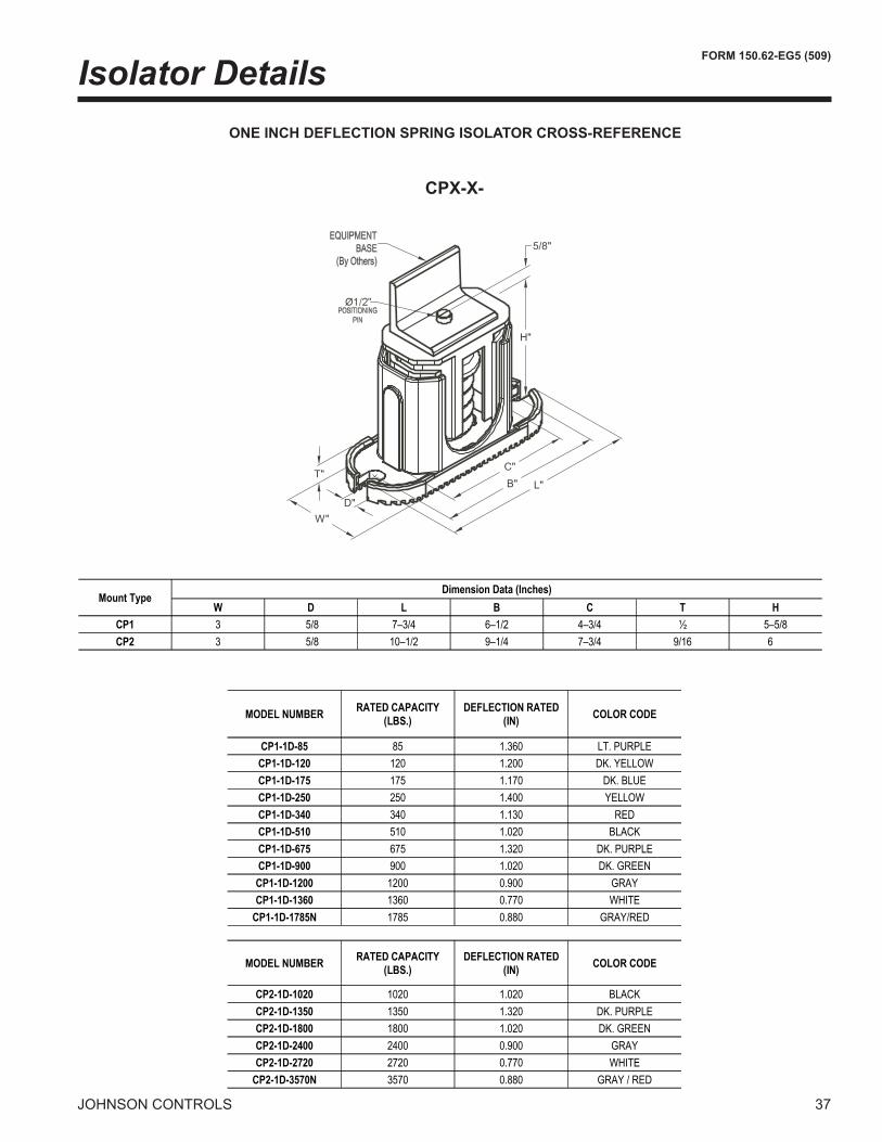
Isolator DetailsONE INCH DEFLECTION SPRING ISOLATOR CROSS-REFERENCE
CPX-X-
����
������
��
��
����
Mount TypeDimension Data (Inches)
W D L B C T H
CP1 3 5/8 7–3/4 6–1/2 4–3/4 ½ 5–5/8
CP2 3 5/8 10–1/2 9–1/4 7–3/4 9/16 6
MODEL NUMBER COLOR CODE
CP1-1D-85 85 1.360 LT. PURPLE
CP1-1D-120 120 1.200 DK. YELLOW
CP1-1D-175 175 1.170 DK. BLUE
CP1-1D-250 250 1.400 YELLOW
CP1-1D-340 340 1.130 RED
CP1-1D-510 510 1.020 BLACK
CP1-1D-675 675 1.320 DK. PURPLE
CP1-1D-900 900 1.020 DK. GREEN
CP1-1D-1200 1200 0.900 GRAY
CP1-1D-1360 1360 0.770 WHITE
CP1-1D-1785N 1785 0.880 GRAY/RED
MODEL NUMBER COLOR CODE
CP2-1D-1020 1020 1.020 BLACK
CP2-1D-1350 1350 1.320 DK. PURPLE
CP2-1D-1800 1800 1.020 DK. GREEN
CP2-1D-2400 2400 0.900 GRAY
CP2-1D-2720 2720 0.770 WHITE
CP2-1D-3570N 3570 0.880 GRAY / RED
RATED CAPACITY
(LBS.)
DEFLECTION RATED
(IN)
RATED CAPACITY
(LBS.)
DEFLECTION RATED
(IN)
�8 jOHNSON CONTROLS
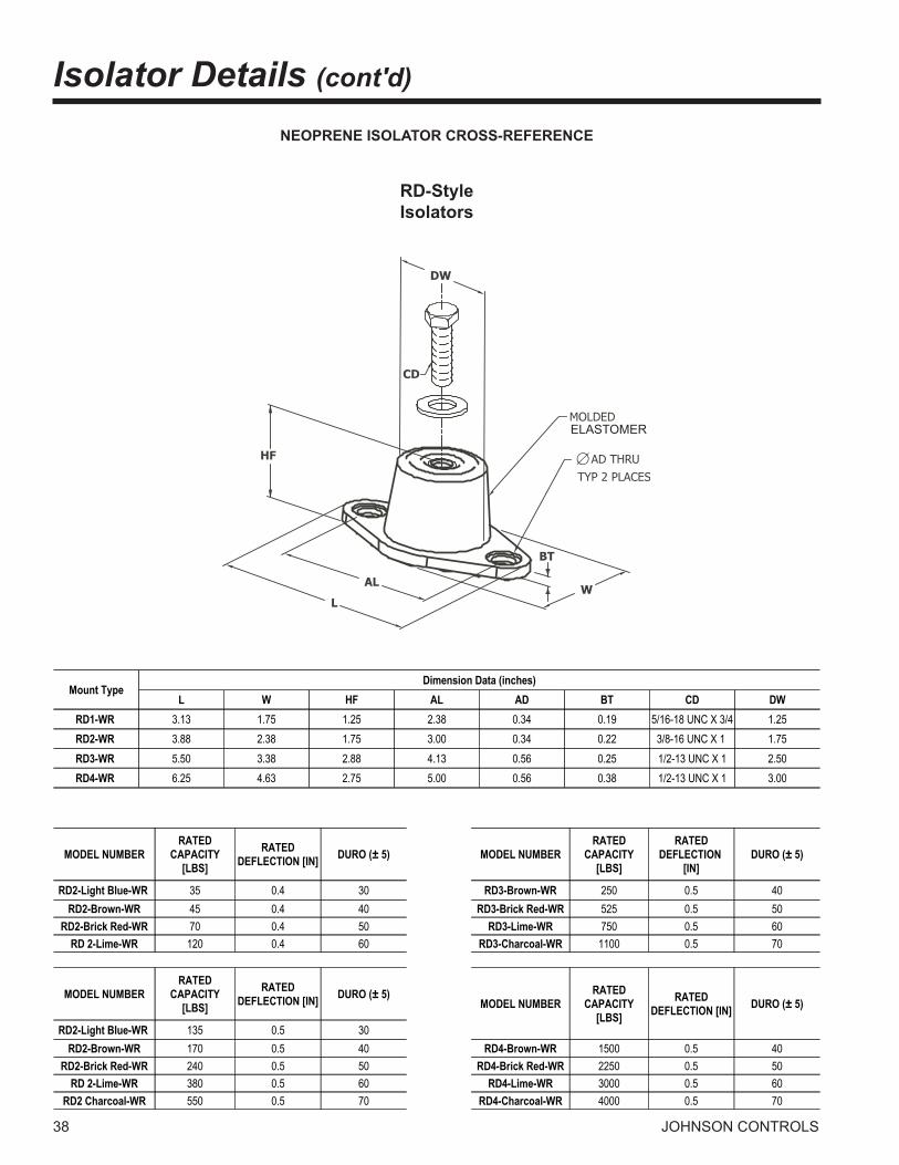
Isolator Details (cont'd)
NEOPRENE ISOLATOR CROSS-REFERENCE
ELASTOMER
RD-Style Isolators
Mount TypeDimension Data (inches)
L W HF AL AD BT CD DW
RD1-WR 3.13 1.75 1.25 2.38 0.34 0.19 5/16-18 UNC X 3/4 1.25
RD2-WR 3.88 2.38 1.75 3.00 0.34 0.22 3/8-16 UNC X 1 1.75
RD3-WR 5.50 3.38 2.88 4.13 0.56 0.25 1/2-13 UNC X 1 2.50
RD4-WR 6.25 4.63 2.75 5.00 0.56 0.38 1/2-13 UNC X 1 3.00
MODEL NUMBER DURO (± 5) MODEL NUMBER DURO (± 5)
RD2-Light Blue-WR 35 0.4 30 RD3-Brown-WR 250 0.5 40
RD2-Brown-WR 45 0.4 40 RD3-Brick Red-WR 525 0.5 50
RD2-Brick Red-WR 70 0.4 50 RD3-Lime-WR 750 0.5 60
RD 2-Lime-WR 120 0.4 60 RD3-Charcoal-WR 1100 0.5 70
MODEL NUMBER DURO (± 5)MODEL NUMBER DURO (± 5)
RD2-Light Blue-WR 135 0.5 30
RD2-Brown-WR 170 0.5 40 RD4-Brown-WR 1500 0.5 40
RD2-Brick Red-WR 240 0.5 50 RD4-Brick Red-WR 2250 0.5 50
RD 2-Lime-WR 380 0.5 60 RD4-Lime-WR 3000 0.5 60
RD2 Charcoal-WR 550 0.5 70 RD4-Charcoal-WR 4000 0.5 70
RATED
CAPACITY
[LBS]
RATED
DEFLECTION [IN]
RATED
CAPACITY
[LBS]
RATED
DEFLECTION
[IN]
RATED
CAPACITY
[LBS]
RATED
DEFLECTION [IN]RATED
CAPACITY
[LBS]
RATED
DEFLECTION [IN]

FORM 150.62-EG5 (509)
�9jOHNSON CONTROLS
TWO INCH DEFLECTION, SEISMIC SPRING ISOLATOR CROSS-REFERENCE
Y2RS
3/4”
7/8”
3/8” GAP
3/4”TYP. (4)
5/8” 2-3/4”
1-1/8”
2-3/4”
8P
4
8
STOP &8-3/8”OPER.HEIGHT
4
4
MODEL Y2RSI-2D SEISMICALLY RESTRAINED VIBRATION ISOLATOR FOR 2" DEFLECTION
SEISMIC MOUNT SIZE RATED LOAD (LBS) SOLID LOAD (LBS) COLOR CODE
Y2RSI-2D-150 150 2.4 62 234 WHITE 34.7
Y2RSI-2D-320 320 2.3 140 490 YELLOW 16.3
Y2RSI-2D-460 460 2.3 200 688 GREEN 11.3
Y2RSI-2D-710 710 2.2 330 1072 DK BROWN 7.3
Y2RSI-2D-870 870 1.9 460 1312 RED 6
Y2RSI-2D-1200N 1200 1.9 638 1818 RED/BLACK 4.3
Y2RSI-2D-1450 1450 1.8 900 2450 TAN 3.6
Y2RSI-2D-1690 1690 1.7 1140 2892 PINK 3.1
Y2RSI-2D-2000N 2000 1.7 1318 3342 PINK/BLACK 2.6
Y2RSI-2D-2640N 2640 1.5 1854 4283 PINK/GRAY 2
Y2RSI-2D-2870N 3080 1.5 2004 4629 PINK/GRAY/ORANGE 1.7
Y2RSI-2D-3280N 3740 1.8 2134 4930 1.4
RATED DEFLECTION
(IN)
SPRING RATE
(LBS/IN)
ALLOWABLE G
RATING HORIZONTAL
PINK/GRAY/DK
BROWN

40 jOHNSON CONTROLS
LEGEND ACR-LINE ACROSS THE LINE START C.B. CIRCUIT BREAKER D.E. DUAL ELEMENT FUSE DISC SW DISCONNECT SWITCH FACT MOUNT CB FACTORY MOUNTED CIRCUIT BREAKER FLA FULL LOAD AMPS HZ HERTZ MAX MAXIMUM MCA MINIMUM CIRCUIT AMPACITY MIN MINIMUM MIN NF MINIMUM NON FUSED RLA RATED LOAD AMPS S.P. WIRE SINGLE POINT WIRING UNIT MTD SERV SW UNIT MOUNTED SERVICE (NON-FUSED DISCONNECT SWITCH) LRA LOCKED ROTOR AMPS
vOLTAGE CODE-17 = �00-�-60-�8 = ��0-�-60-40 = �80-�-60-46 = 460-�-60-58 = 575-�-60
1. Minimum Circuit Ampacity (MCA) is based on 1�5% of the rated load amps for the largest motor plus 100% of the rated load amps for all other loads included in the circuit, per N.E.C. Article 4�0-�4. If the optional Factory Mounted Control Transformer is provided, add the following MCA values to the electrical tables for the system providing power to the transformer: -17, add �.5 amps; -�8, add �.� amps; -40, add 1.5 amps, -46, add 1.� amps; -58, add 1 amps.
�. The minimum recommended disconnect switch is based on 115% of the rated load amps for all loads included in the circuit, per N.E.C. Article 440.
�. Minimum fuse size is based upon 150% of the rated load amps for the largest motor plus 100% of the rated load amps for all other loads included in the circuit to avoid nuisance trips at start-up due to lock rotor amps. It is not rec-ommended in applications where brown outs, frequent starting and stopping of the unit, and/or operation at ambient temperatures in excess of 95ºF (�5ºC) is anticipated.
4. Maximum fuse size is based upon ��5% of the rated load amps for the largest motor plus 100% of the rated load amps for all other loads included in the circuit, per N.E.C. Article 440-��.
5. Circuit breakers must be UL listed and CSA certified and maximum size is based on 225% of the rated load amps for the largest motor plus 100% of the rated load amps for all other loads included in the circuit. Otherwise, HACR-type circuit breakers must be used. Maximum HACR circuit breaker rating is based on ��5% of the rated load amps for the largest motor plus 100% of the rated load amps for all other loads included in the circuit.
6. The “INCOMING WIRE RANGE” is the minimum and maximum wire size that can be accommodated by the unit wir-ing lugs. The (�) preceding the wire range indicates the number of termination points available per phase of the wire range specified. Actual wire size and number of wires per phase must be determined based on the National Electrical Code, using copper connectors only. Field wiring must also comply with local codes.
7. A ground lug is provided for each compressor system to accommodate a field grounding conductor per N.E.C. Table �50-95. A control circuit grounding lug is also supplied.
8. The supplied disconnect is a “Disconnecting Means” as defined in the N.E.C. 100, and is intended for isolating the unit for the available power supply to perform maintenance and troubleshooting. This disconnect is not intended to be a Load Break Device.
9. Field Wiring by others which complies to the National Electrical Code & Local Codes.
NOTES:
Electrical Notes

FORM 150.62-EG5 (509)
41jOHNSON CONTROLS
INTENTIONALLY LEFT BLANK

4� jOHNSON CONTROLS
Electrical Data w/o Pumps
CHILLER MODEL
Volt-age MCA
MIN N/F DS
MIN DUAL ELEM FUSE
MAX DUAL ELEM FUSEMAX CB
SYSTEM # 1 SYSTEM # 2 Lug SizingCOMPR 1 COMPR 2 COMPR 3 FAN COMPR 1 COMPR 2 COMPR 3 FAN
Non-Fuse Disc Sw. Circuit Breaker Terminal Block
RLA LRA RLA LRA RLA LRA QTY FLA LRA RLA LRA RLA LRA RLA LRA QTY FLA LRARating Size Lug Rating Size Lug Lug
0070
200 351 400 400 400 51 300 51 300 51 300 2 7.6 31 51 300 51 300 51 300 2 7.6 31 600 S6-600 S6: (2) 250kcmil - 500kcmil 400 S5-400 S5: (2) 3/0 - 250kcmil (4) 4AWG - 500kcmil230 350 400 400 400 51 300 51 300 51 300 2 7.4 37 51 300 51 300 51 300 2 7.4 37 600 S6-600 S6: (2) 250kcmil - 500kcmil 400 S5-400 S5: (2) 3/0 - 250kcmil (4) 4AWG - 500kcmil380 186 250 200 200 27 139 27 139 27 139 2 4.5 22 27 139 27 139 27 139 2 4.5 22 250 S4-250 S4: 6AWG - 350kcmil 200 S3-225 S3-S4-S5: 4AWG - 300kcmil (2) 4AWG - 500kcmil460 160 200 175 175 23 150 23 150 23 150 2 4.0 19 23 150 23 150 23 150 2 4.0 19 200 S3-225 S3-S4-S5: 4AWG - 300kcmil 175 S3-175 S3-S4-S5: 4AWG - 300kcmil (2) 4AWG - 500kcmil575 136 200 150 150 20 109 20 109 20 109 2 2.9 15 20 109 20 109 20 109 2 2.9 15 200 S3-225 S3-S4-S5: 4AWG - 300kcmil 150 S3-150 S3-S4: 2AWG - 4/0 (2) 4AWG - 500kcmil
0080
200 366 600 400 400 56 425 56 425 56 425 2 7.6 31 51 300 51 300 51 300 2 7.6 31 600 S6-600 S6: (2) 250kcmil - 500kcmil 400 S5-400 S5: (2) 3/0 - 250kcmil (4) 4AWG - 500kcmil230 365 600 400 400 56 425 56 425 56 425 2 7.4 37 51 300 51 300 51 300 2 7.4 37 600 S6-600 S6: (2) 250kcmil - 500kcmil 400 S5-400 S5: (2) 3/0 - 250kcmil (4) 4AWG - 500kcmil380 216 250 225 250 36 239 36 239 36 239 2 4.5 22 27 139 27 139 27 139 2 4.5 22 400 S5-400 S5: (2) 3/0 - 250kcmil 250 S4-250 S4: 6AWG - 350kcmil (2) 4AWG - 500kcmil460 173 200 200 200 27 187 27 187 27 187 2 4.0 19 23 150 23 150 23 150 2 4.0 19 250 S4-250 S4: 6AWG - 350kcmil 200 S3-225 S3-S4-S5: 4AWG - 300kcmil (2) 4AWG - 500kcmil575 148 200 175 175 24 148 24 148 24 148 2 2.9 15 20 109 20 109 20 109 2 2.9 15 200 S3-225 S3-S4-S5: 4AWG - 300kcmil 175 S3-175 S3-S4-S5: 4AWG - 300kcmil (2) 4AWG - 500kcmil
0090
200 391 600 450 500 56 425 56 425 56 425 2 7.6 31 110 599 56 425 2 7.6 31 600 S6-600 S6: (2) 250kcmil - 500kcmil 500 S6-600 S6: (2) 250kcmil - 500kcmil (4) 4AWG - 500kcmil230 390 600 450 450 56 425 56 425 56 425 2 7.4 37 110 599 56 425 2 7.4 37 600 S6-600 S6: (2) 250kcmil - 500kcmil 450 S6-600 S6: (2) 250kcmil - 500kcmil (4) 4AWG - 500kcmil380 249 400 300 300 36 239 36 239 36 239 2 4.5 22 69 358 36 239 2 4.5 22 400 S5-400 S5: (2) 3/0 - 250kcmil 300 S5-400 S5: (2) 3/0 - 250kcmil (2) 4AWG - 500kcmil460 192 250 225 225 27 187 27 187 27 187 2 4.0 19 55 310 27 187 2 4.0 19 250 S4-250 S4: 6AWG - 350kcmil 225 S3-225 S3-S4-S5: 4AWG - 300kcmil (2) 4AWG - 500kcmil575 168 200 200 200 24 148 24 148 24 148 2 2.9 15 49 239 24 148 2 2.9 15 250 S4-250 S4: 6AWG - 350kcmil 200 S3-225 S3-S4-S5: 4AWG - 300kcmil (2) 4AWG - 500kcmil
0091
200 404 600 450 500 110 599 56 425 3 7.6 31 110 599 56 425 3 7.6 31 600 S6-600 S6: (2) 250kcmil - 500kcmil 500 S6-600 S6: (2) 250kcmil - 500kcmil (4) 4AWG - 500kcmil230 403 600 450 500 110 358 56 425 3 7.4 37 110 599 56 425 3 7.4 37 600 S6-600 S6: (2) 250kcmil - 500kcmil 500 S6-600 S6: (2) 250kcmil - 500kcmil (4) 4AWG - 500kcmil380 255 400 300 300 69 310 36 239 3 4.5 22 69 358 36 239 3 4.5 22 400 S5-400 S5: (2) 3/0 - 250kcmil 300 S5-400 S5: (2) 3/0 - 250kcmil (2) 4AWG - 500kcmil460 200 250 225 250 55 239 27 187 3 4.0 19 55 310 27 187 3 4.0 19 250 S4-250 S4: 6AWG - 350kcmil 250 S4-250 S4: 6AWG - 350kcmil (2) 4AWG - 500kcmil575 176 200 200 225 49 310 24 148 3 2.9 15 49 239 24 148 3 2.9 15 250 S4-250 S4: 6AWG - 350kcmil 225 S3-225 S3-S4-S5: 4AWG - 300kcmil (2) 4AWG - 500kcmil
0101
200 460 600 500 500 56 425 56 425 56 425 2 7.6 31 110 599 110 599 4 7.6 31 600 S6-600 S6: (2) 250kcmil - 500kcmil 500 S6-600 S6: (2) 250kcmil - 500kcmil (4) 4AWG - 500kcmil230 458 600 500 500 56 425 56 425 56 425 2 7.4 37 110 599 110 599 4 7.4 37 600 S6-600 S6: (2) 250kcmil - 500kcmil 500 S6-600 S6: (2) 250kcmil - 500kcmil (4) 4AWG - 500kcmil380 291 400 350 350 36 239 36 239 36 239 2 4.5 22 69 358 69 358 4 4.5 22 400 S5-400 S5: (2) 3/0 - 250kcmil 350 S5-400 S5: (2) 3/0 - 250kcmil (2) 4AWG - 500kcmil460 227 250 250 250 27 187 27 187 27 187 2 4.0 19 55 310 55 310 4 4.0 19 400 S5-400 S5: (2) 3/0 - 250kcmil 250 S4-250 S4: 6AWG - 350kcmil (2) 4AWG - 500kcmil575 200 250 225 225 24 148 24 148 24 148 2 2.9 15 49 239 49 239 4 2.9 15 250 S4-250 S4: 6AWG - 350kcmil 225 S3-225 S3-S4-S5: 4AWG - 300kcmil (2) 4AWG - 500kcmil
0115 0120
200 511 600 600 600 110 599 110 599 3 7.6 31 110 599 110 599 3 7.6 31 800 S6-800 S6: (3) 2/0 - 400kcmil 600 S6-600 S6: (2) 250kcmil - 500kcmil (4) 4AWG - 500kcmil230 510 600 600 600 110 599 110 599 3 7.4 37 110 599 110 599 3 7.4 37 800 S6-800 S6: (3) 2/0 - 400kcmil 600 S6-600 S6: (2) 250kcmil - 500kcmil (4) 4AWG - 500kcmil380 321 400 350 350 69 358 69 358 3 4.5 22 69 358 69 358 3 4.5 22 400 S5-400 S5: (2) 3/0 - 250kcmil 350 S5-400 S5: (2) 3/0 - 250kcmil (4) 4AWG - 500kcmil460 255 400 300 300 55 310 55 310 3 4.0 19 55 310 55 310 3 4.0 19 400 S5-400 S5: (2) 3/0 - 250kcmil 300 S5-400 S5: (2) 3/0 - 250kcmil (2) 4AWG - 500kcmil575 227 250 250 250 49 239 49 239 3 2.9 15 49 239 49 239 3 2.9 15 400 S5-400 S5: (2) 3/0 - 250kcmil 250 S4-250 S4: 6AWG - 350kcmil (2) 4AWG - 500kcmil
0135
200 582 800 700 700 110 599 110 599 110 599 4 7.6 31 110 599 56 425 4 7.6 31 800 S6-800 S6: (3) 2/0 - 400kcmil 700 S6-800 S6: (3) 2/0 - 400kcmil (4) 4AWG - 500kcmil230 581 800 700 700 110 599 110 599 110 599 4 7.4 37 110 599 56 425 4 7.4 37 800 S6-800 S6: (3) 2/0 - 400kcmil 700 S6-800 S6: (3) 2/0 - 400kcmil (4) 4AWG - 500kcmil380 366 600 400 400 69 358 69 358 69 358 4 4.5 22 69 358 36 239 4 4.5 22 600 S6-600 S6: (2) 250kcmil - 500kcmil 400 S5-400 S5: (2) 3/0 - 250kcmil (4) 4AWG - 500kcmil460 291 400 350 350 55 310 55 310 55 310 4 4.0 19 55 310 27 187 4 4.0 19 400 S5-400 S5: (2) 3/0 - 250kcmil 350 S5-400 S5: (2) 3/0 - 250kcmil (2) 4AWG - 500kcmil575 257 400 300 300 49 239 49 239 49 239 4 2.9 15 49 239 24 148 4 2.9 15 400 S5-400 S5: (2) 3/0 - 250kcmil 300 S5-400 S5: (2) 3/0 - 250kcmil (2) 4AWG - 500kcmil
0150 0155
200 636 800 700 700 110 599 110 599 110 599 4 7.6 31 110 599 110 599 4 7.6 31 800 S6-800 S6: (3) 2/0 - 400kcmil 700 S6-800 S6: (3) 2/0 - 400kcmil (4) 4AWG - 500kcmil230 635 800 700 700 110 599 110 599 110 599 4 7.4 37 110 599 110 599 4 7.4 37 800 S6-800 S6: (3) 2/0 - 400kcmil 700 S6-800 S6: (3) 2/0 - 400kcmil (4) 4AWG - 500kcmil380 399 600 450 450 69 358 69 358 69 358 4 4.5 22 69 358 69 358 4 4.5 22 600 S6-600 S6: (2) 250kcmil - 500kcmil 450 S6-600 S6: (2) 250kcmil - 500kcmil (4) 4AWG - 500kcmil460 318 400 350 350 55 310 55 310 55 310 4 4.0 19 55 310 55 310 4 4.0 19 400 S5-400 S5: (2) 3/0 - 250kcmil 350 S5-400 S5: (2) 3/0 - 250kcmil (4) 4AWG - 500kcmil575 283 3800 300 300 49 2309 49 2309 49 2309 4 2.9 15 49 2309 49 2309 4 2.9 15 3800 S5-3800 S5: (2) 3/0 - 250kcmil 300 S5-3800 S5: (2) 3/0 - 250kcmil (2) 4AWG - 500kcmil

FORM 150.62-EG5 (509)
4�jOHNSON CONTROLS
CHILLER MODEL
Volt-age MCA
MIN N/F DS
MIN DUAL ELEM FUSE
MAX DUAL ELEM FUSEMAX CB
SYSTEM # 1 SYSTEM # 2 Lug SizingCOMPR 1 COMPR 2 COMPR 3 FAN COMPR 1 COMPR 2 COMPR 3 FAN
Non-Fuse Disc Sw. Circuit Breaker Terminal Block
RLA LRA RLA LRA RLA LRA QTY FLA LRA RLA LRA RLA LRA RLA LRA QTY FLA LRARating Size Lug Rating Size Lug Lug
0070
200 351 400 400 400 51 300 51 300 51 300 2 7.6 31 51 300 51 300 51 300 2 7.6 31 600 S6-600 S6: (2) 250kcmil - 500kcmil 400 S5-400 S5: (2) 3/0 - 250kcmil (4) 4AWG - 500kcmil230 350 400 400 400 51 300 51 300 51 300 2 7.4 37 51 300 51 300 51 300 2 7.4 37 600 S6-600 S6: (2) 250kcmil - 500kcmil 400 S5-400 S5: (2) 3/0 - 250kcmil (4) 4AWG - 500kcmil380 186 250 200 200 27 139 27 139 27 139 2 4.5 22 27 139 27 139 27 139 2 4.5 22 250 S4-250 S4: 6AWG - 350kcmil 200 S3-225 S3-S4-S5: 4AWG - 300kcmil (2) 4AWG - 500kcmil460 160 200 175 175 23 150 23 150 23 150 2 4.0 19 23 150 23 150 23 150 2 4.0 19 200 S3-225 S3-S4-S5: 4AWG - 300kcmil 175 S3-175 S3-S4-S5: 4AWG - 300kcmil (2) 4AWG - 500kcmil575 136 200 150 150 20 109 20 109 20 109 2 2.9 15 20 109 20 109 20 109 2 2.9 15 200 S3-225 S3-S4-S5: 4AWG - 300kcmil 150 S3-150 S3-S4: 2AWG - 4/0 (2) 4AWG - 500kcmil
0080
200 366 600 400 400 56 425 56 425 56 425 2 7.6 31 51 300 51 300 51 300 2 7.6 31 600 S6-600 S6: (2) 250kcmil - 500kcmil 400 S5-400 S5: (2) 3/0 - 250kcmil (4) 4AWG - 500kcmil230 365 600 400 400 56 425 56 425 56 425 2 7.4 37 51 300 51 300 51 300 2 7.4 37 600 S6-600 S6: (2) 250kcmil - 500kcmil 400 S5-400 S5: (2) 3/0 - 250kcmil (4) 4AWG - 500kcmil380 216 250 225 250 36 239 36 239 36 239 2 4.5 22 27 139 27 139 27 139 2 4.5 22 400 S5-400 S5: (2) 3/0 - 250kcmil 250 S4-250 S4: 6AWG - 350kcmil (2) 4AWG - 500kcmil460 173 200 200 200 27 187 27 187 27 187 2 4.0 19 23 150 23 150 23 150 2 4.0 19 250 S4-250 S4: 6AWG - 350kcmil 200 S3-225 S3-S4-S5: 4AWG - 300kcmil (2) 4AWG - 500kcmil575 148 200 175 175 24 148 24 148 24 148 2 2.9 15 20 109 20 109 20 109 2 2.9 15 200 S3-225 S3-S4-S5: 4AWG - 300kcmil 175 S3-175 S3-S4-S5: 4AWG - 300kcmil (2) 4AWG - 500kcmil
0090
200 391 600 450 500 56 425 56 425 56 425 2 7.6 31 110 599 56 425 2 7.6 31 600 S6-600 S6: (2) 250kcmil - 500kcmil 500 S6-600 S6: (2) 250kcmil - 500kcmil (4) 4AWG - 500kcmil230 390 600 450 450 56 425 56 425 56 425 2 7.4 37 110 599 56 425 2 7.4 37 600 S6-600 S6: (2) 250kcmil - 500kcmil 450 S6-600 S6: (2) 250kcmil - 500kcmil (4) 4AWG - 500kcmil380 249 400 300 300 36 239 36 239 36 239 2 4.5 22 69 358 36 239 2 4.5 22 400 S5-400 S5: (2) 3/0 - 250kcmil 300 S5-400 S5: (2) 3/0 - 250kcmil (2) 4AWG - 500kcmil460 192 250 225 225 27 187 27 187 27 187 2 4.0 19 55 310 27 187 2 4.0 19 250 S4-250 S4: 6AWG - 350kcmil 225 S3-225 S3-S4-S5: 4AWG - 300kcmil (2) 4AWG - 500kcmil575 168 200 200 200 24 148 24 148 24 148 2 2.9 15 49 239 24 148 2 2.9 15 250 S4-250 S4: 6AWG - 350kcmil 200 S3-225 S3-S4-S5: 4AWG - 300kcmil (2) 4AWG - 500kcmil
0091
200 404 600 450 500 110 599 56 425 3 7.6 31 110 599 56 425 3 7.6 31 600 S6-600 S6: (2) 250kcmil - 500kcmil 500 S6-600 S6: (2) 250kcmil - 500kcmil (4) 4AWG - 500kcmil230 403 600 450 500 110 358 56 425 3 7.4 37 110 599 56 425 3 7.4 37 600 S6-600 S6: (2) 250kcmil - 500kcmil 500 S6-600 S6: (2) 250kcmil - 500kcmil (4) 4AWG - 500kcmil380 255 400 300 300 69 310 36 239 3 4.5 22 69 358 36 239 3 4.5 22 400 S5-400 S5: (2) 3/0 - 250kcmil 300 S5-400 S5: (2) 3/0 - 250kcmil (2) 4AWG - 500kcmil460 200 250 225 250 55 239 27 187 3 4.0 19 55 310 27 187 3 4.0 19 250 S4-250 S4: 6AWG - 350kcmil 250 S4-250 S4: 6AWG - 350kcmil (2) 4AWG - 500kcmil575 176 200 200 225 49 310 24 148 3 2.9 15 49 239 24 148 3 2.9 15 250 S4-250 S4: 6AWG - 350kcmil 225 S3-225 S3-S4-S5: 4AWG - 300kcmil (2) 4AWG - 500kcmil
0101
200 460 600 500 500 56 425 56 425 56 425 2 7.6 31 110 599 110 599 4 7.6 31 600 S6-600 S6: (2) 250kcmil - 500kcmil 500 S6-600 S6: (2) 250kcmil - 500kcmil (4) 4AWG - 500kcmil230 458 600 500 500 56 425 56 425 56 425 2 7.4 37 110 599 110 599 4 7.4 37 600 S6-600 S6: (2) 250kcmil - 500kcmil 500 S6-600 S6: (2) 250kcmil - 500kcmil (4) 4AWG - 500kcmil380 291 400 350 350 36 239 36 239 36 239 2 4.5 22 69 358 69 358 4 4.5 22 400 S5-400 S5: (2) 3/0 - 250kcmil 350 S5-400 S5: (2) 3/0 - 250kcmil (2) 4AWG - 500kcmil460 227 250 250 250 27 187 27 187 27 187 2 4.0 19 55 310 55 310 4 4.0 19 400 S5-400 S5: (2) 3/0 - 250kcmil 250 S4-250 S4: 6AWG - 350kcmil (2) 4AWG - 500kcmil575 200 250 225 225 24 148 24 148 24 148 2 2.9 15 49 239 49 239 4 2.9 15 250 S4-250 S4: 6AWG - 350kcmil 225 S3-225 S3-S4-S5: 4AWG - 300kcmil (2) 4AWG - 500kcmil
0115 0120
200 511 600 600 600 110 599 110 599 3 7.6 31 110 599 110 599 3 7.6 31 800 S6-800 S6: (3) 2/0 - 400kcmil 600 S6-600 S6: (2) 250kcmil - 500kcmil (4) 4AWG - 500kcmil230 510 600 600 600 110 599 110 599 3 7.4 37 110 599 110 599 3 7.4 37 800 S6-800 S6: (3) 2/0 - 400kcmil 600 S6-600 S6: (2) 250kcmil - 500kcmil (4) 4AWG - 500kcmil380 321 400 350 350 69 358 69 358 3 4.5 22 69 358 69 358 3 4.5 22 400 S5-400 S5: (2) 3/0 - 250kcmil 350 S5-400 S5: (2) 3/0 - 250kcmil (4) 4AWG - 500kcmil460 255 400 300 300 55 310 55 310 3 4.0 19 55 310 55 310 3 4.0 19 400 S5-400 S5: (2) 3/0 - 250kcmil 300 S5-400 S5: (2) 3/0 - 250kcmil (2) 4AWG - 500kcmil575 227 250 250 250 49 239 49 239 3 2.9 15 49 239 49 239 3 2.9 15 400 S5-400 S5: (2) 3/0 - 250kcmil 250 S4-250 S4: 6AWG - 350kcmil (2) 4AWG - 500kcmil
0135
200 582 800 700 700 110 599 110 599 110 599 4 7.6 31 110 599 56 425 4 7.6 31 800 S6-800 S6: (3) 2/0 - 400kcmil 700 S6-800 S6: (3) 2/0 - 400kcmil (4) 4AWG - 500kcmil230 581 800 700 700 110 599 110 599 110 599 4 7.4 37 110 599 56 425 4 7.4 37 800 S6-800 S6: (3) 2/0 - 400kcmil 700 S6-800 S6: (3) 2/0 - 400kcmil (4) 4AWG - 500kcmil380 366 600 400 400 69 358 69 358 69 358 4 4.5 22 69 358 36 239 4 4.5 22 600 S6-600 S6: (2) 250kcmil - 500kcmil 400 S5-400 S5: (2) 3/0 - 250kcmil (4) 4AWG - 500kcmil460 291 400 350 350 55 310 55 310 55 310 4 4.0 19 55 310 27 187 4 4.0 19 400 S5-400 S5: (2) 3/0 - 250kcmil 350 S5-400 S5: (2) 3/0 - 250kcmil (2) 4AWG - 500kcmil575 257 400 300 300 49 239 49 239 49 239 4 2.9 15 49 239 24 148 4 2.9 15 400 S5-400 S5: (2) 3/0 - 250kcmil 300 S5-400 S5: (2) 3/0 - 250kcmil (2) 4AWG - 500kcmil
0150 0155
200 636 800 700 700 110 599 110 599 110 599 4 7.6 31 110 599 110 599 4 7.6 31 800 S6-800 S6: (3) 2/0 - 400kcmil 700 S6-800 S6: (3) 2/0 - 400kcmil (4) 4AWG - 500kcmil230 635 800 700 700 110 599 110 599 110 599 4 7.4 37 110 599 110 599 4 7.4 37 800 S6-800 S6: (3) 2/0 - 400kcmil 700 S6-800 S6: (3) 2/0 - 400kcmil (4) 4AWG - 500kcmil380 399 600 450 450 69 358 69 358 69 358 4 4.5 22 69 358 69 358 4 4.5 22 600 S6-600 S6: (2) 250kcmil - 500kcmil 450 S6-600 S6: (2) 250kcmil - 500kcmil (4) 4AWG - 500kcmil460 318 400 350 350 55 310 55 310 55 310 4 4.0 19 55 310 55 310 4 4.0 19 400 S5-400 S5: (2) 3/0 - 250kcmil 350 S5-400 S5: (2) 3/0 - 250kcmil (4) 4AWG - 500kcmil575 283 3800 300 300 49 2309 49 2309 49 2309 4 2.9 15 49 2309 49 2309 4 2.9 15 3800 S5-3800 S5: (2) 3/0 - 250kcmil 300 S5-3800 S5: (2) 3/0 - 250kcmil (2) 4AWG - 500kcmil

44 jOHNSON CONTROLS
Electrical Data w/ Pumps
CHILLER MODEL
Pump Model Voltage Pump
FLA MCAMIN N/F DS
MIN DUAL ELEM FUSE
MAX DUAL ELEM FUSE
MAX CB
SYSTEM # 1 SYSTEM # 2Non-Fuse Disc Sw.
COMPR 1 COMPR 2 COMPR 3 FAN COMPR 1 COMPR 2 COMPR 3 FAN
RLA LRA RLA LRA RLA LRA QTY FLA LRA RLA LRA RLA LRA RLA LRA QTY FLA LRA Rating Size Lug
0070 A, K
200 15.4 366 600 400 400 51 300 51 300 51 300 2 7.6 31 51 300 51 300 51 300 2 7.6 31 600 S6-600 S6: (2) 250kcmil - 500kcmil230 13.9 364 600 400 400 51 300 51 300 51 300 2 7.4 37 51 300 51 300 51 300 2 7.4 37 250 S4-250 S4: 6AWG - 350kcmil380 8.1 194 250 225 225 27 139 27 139 27 139 2 4.5 22 27 139 27 139 27 139 2 4.5 22 200 S3-225 S3-S4-S5: 4AWG - 300kcmil460 6.95 167 200 175 175 23 150 23 150 23 150 2 4.0 19 23 150 23 150 23 150 2 4.0 19 200 S3-225 S3-S4-S5: 4AWG - 300kcmil575 5.56 142 200 150 150 20 109 20 109 20 109 2 2.9 15 20 109 20 109 20 109 2 2.9 15 600 S6-600 S6: (2) 250kcmil - 500kcmil
0070 B
200 21.4 372 600 400 400 51 300 51 300 51 300 2 7.6 31 51 300 51 300 51 300 2 7.6 31 600 S6-600 S6: (2) 250kcmil - 500kcmil230 20.4 371 600 400 400 51 300 51 300 51 300 2 7.4 37 51 300 51 300 51 300 2 7.4 37 250 S4-250 S4: 6AWG - 350kcmil380 12 198 250 225 225 27 139 27 139 27 139 2 4.5 22 27 139 27 139 27 139 2 4.5 22 200 S3-225 S3-S4-S5: 4AWG - 300kcmil460 10.2 171 200 200 200 23 150 23 150 23 150 2 4.0 19 23 150 23 150 23 150 2 4.0 19 200 S3-225 S3-S4-S5: 4AWG - 300kcmil575 8.2 144 200 150 150 20 109 20 109 20 109 2 2.9 15 20 109 20 109 20 109 2 2.9 15 600 S6-600 S6: (2) 250kcmil - 500kcmil
0070 C
200 32.2 383 600 400 400 51 300 51 300 51 300 2 7.6 31 51 300 51 300 51 300 2 7.6 31 600 S6-600 S6: (2) 250kcmil - 500kcmil230 28.4 379 600 400 400 51 300 51 300 51 300 2 7.4 37 51 300 51 300 51 300 2 7.4 37 250 S4-250 S4: 6AWG - 350kcmil380 15.4 202 250 225 225 27 139 27 139 27 139 2 4.5 22 27 139 27 139 27 139 2 4.5 22 200 S3-225 S3-S4-S5: 4AWG - 300kcmil460 14.2 175 200 200 200 23 150 23 150 23 150 2 4.0 19 23 150 23 150 23 150 2 4.0 19 200 S3-225 S3-S4-S5: 4AWG - 300kcmil575 11.4 147 200 175 150 20 109 20 109 20 109 2 2.9 15 20 109 20 109 20 109 2 2.9 15 600 S6-600 S6: (2) 250kcmil - 500kcmil
0070 D, M, N
200 41.7 393 600 450 450 51 300 51 300 51 300 2 7.6 31 51 300 51 300 51 300 2 7.6 31 600 S6-600 S6: (2) 250kcmil - 500kcmil230 36.3 387 600 400 400 51 300 51 300 51 300 2 7.4 37 51 300 51 300 51 300 2 7.4 37 250 S4-250 S4: 6AWG - 350kcmil380 22.03 208 250 225 225 27 139 27 139 27 139 2 4.5 22 27 139 27 139 27 139 2 4.5 22 200 S3-225 S3-S4-S5: 4AWG - 300kcmil460 18.2 179 200 200 200 23 150 23 150 23 150 2 4.0 19 23 150 23 150 23 150 2 4.0 19 200 S3-225 S3-S4-S5: 4AWG - 300kcmil575 14.5 150 200 175 175 20 109 20 109 20 109 2 2.9 15 20 109 20 109 20 109 2 2.9 15 600 S6-600 S6: (2) 250kcmil - 500kcmil
0070 L
200 27.1 378 600 400 400 51 300 51 300 51 300 2 7.6 31 51 300 51 300 51 300 2 7.6 31 600 S6-600 S6: (2) 250kcmil - 500kcmil230 24.5 375 600 400 400 51 300 51 300 51 300 2 7.4 37 51 300 51 300 51 300 2 7.4 37 250 S4-250 S4: 6AWG - 350kcmil380 14.8 201 250 225 225 27 139 27 139 27 139 2 4.5 22 27 139 27 139 27 139 2 4.5 22 200 S3-225 S3-S4-S5: 4AWG - 300kcmil460 12.3 173 200 200 200 23 150 23 150 23 150 2 4.0 19 23 150 23 150 23 150 2 4.0 19 200 S3-225 S3-S4-S5: 4AWG - 300kcmil575 9.84 146 200 175 175 20 109 20 109 20 109 2 2.9 15 20 109 20 109 20 109 2 2.9 15 600 S6-600 S6: (2) 250kcmil - 500kcmil
0080 A, K
200 15.4 381 600 400 400 56 425 56 425 56 425 2 7.6 31 51 300 51 300 51 300 2 7.6 31 600 S6-600 S6: (2) 250kcmil - 500kcmil230 13.9 379 600 400 400 56 425 56 425 56 425 2 7.4 37 51 300 51 300 51 300 2 7.4 37 400 S5-400 S5: (2) 3/0 - 250kcmil380 8.1 224 250 250 250 36 239 36 239 36 239 2 4.5 22 27 139 27 139 27 139 2 4.5 22 250 S4-250 S4: 6AWG - 350kcmil460 6.95 180 200 200 200 27 187 27 187 27 187 2 4.0 19 23 150 23 150 23 150 2 4.0 19 200 S3-225 S3-S4-S5: 4AWG - 300kcmil575 5.56 154 200 175 175 24 148 24 148 24 148 2 2.9 15 20 109 20 109 20 109 2 2.9 15 600 S6-600 S6: (2) 250kcmil - 500kcmil
0080 B
200 21.4 387 600 450 450 56 425 56 425 56 425 2 7.6 31 51 300 51 300 51 300 2 7.6 31 600 S6-600 S6: (2) 250kcmil - 500kcmil230 20.4 385 600 400 400 56 425 56 425 56 425 2 7.4 37 51 300 51 300 51 300 2 7.4 37 400 S5-400 S5: (2) 3/0 - 250kcmil380 12 228 400 250 250 36 239 36 239 36 239 2 4.5 22 27 139 27 139 27 139 2 4.5 22 250 S4-250 S4: 6AWG - 350kcmil460 10.2 183 250 200 200 27 187 27 187 27 187 2 4.0 19 23 150 23 150 23 150 2 4.0 19 200 S3-225 S3-S4-S5: 4AWG - 300kcmil575 8.2 157 200 175 175 24 148 24 148 24 148 2 2.9 15 20 109 20 109 20 109 2 2.9 15 600 S6-600 S6: (2) 250kcmil - 500kcmil
0080 C
200 32.2 398 600 450 450 56 425 56 425 56 425 2 7.6 31 51 300 51 300 51 300 2 7.6 31 600 S6-600 S6: (2) 250kcmil - 500kcmil230 28.4 393 600 450 450 56 425 56 425 56 425 2 7.4 37 51 300 51 300 51 300 2 7.4 37 400 S5-400 S5: (2) 3/0 - 250kcmil380 15.4 231 400 250 250 36 239 36 239 36 239 2 4.5 22 27 139 27 139 27 139 2 4.5 22 250 S4-250 S4: 6AWG - 350kcmil460 14.2 187 250 200 200 27 187 27 187 27 187 2 4.0 19 23 150 23 150 23 150 2 4.0 19 200 S3-225 S3-S4-S5: 4AWG - 300kcmil575 11.4 160 200 175 175 24 148 24 148 24 148 2 2.9 15 20 109 20 109 20 109 2 2.9 15 600 S6-600 S6: (2) 250kcmil - 500kcmil
0080 D, M, N
200 41.7 407 600 450 450 56 425 56 425 56 425 2 7.6 31 51 300 51 300 51 300 2 7.6 31 600 S6-600 S6: (2) 250kcmil - 500kcmil230 36.3 401 600 450 450 56 425 56 425 56 425 2 7.4 37 51 300 51 300 51 300 2 7.4 37 400 S5-400 S5: (2) 3/0 - 250kcmil380 22.03 238 400 250 250 36 239 36 239 36 239 2 4.5 22 27 139 27 139 27 139 2 4.5 22 250 S4-250 S4: 6AWG - 350kcmil460 18.2 191 250 200 200 27 187 27 187 27 187 2 4.0 19 23 150 23 150 23 150 2 4.0 19 200 S3-225 S3-S4-S5: 4AWG - 300kcmil575 14.5 163 200 175 175 24 148 24 148 24 148 2 2.9 15 20 109 20 109 20 109 2 2.9 15 600 S6-600 S6: (2) 250kcmil - 500kcmil
0080 L
200 27.1 393 600 450 450 56 425 56 425 56 425 2 7.6 31 51 300 51 300 51 300 2 7.6 31 600 S6-600 S6: (2) 250kcmil - 500kcmil230 24.5 389 600 450 450 56 425 56 425 56 425 2 7.4 37 51 300 51 300 51 300 2 7.4 37 400 S5-400 S5: (2) 3/0 - 250kcmil380 14.8 231 400 250 250 36 239 36 239 36 239 2 4.5 22 27 139 27 139 27 139 2 4.5 22 250 S4-250 S4: 6AWG - 350kcmil460 12.3 185 250 200 200 27 187 27 187 27 187 2 4.0 19 23 150 23 150 23 150 2 4.0 19 200 S3-225 S3-S4-S5: 4AWG - 300kcmil575 9.84 158 200 175 175 24 148 24 148 24 148 2 2.9 15 20 109 20 109 20 109 2 2.9 15 600 S6-600 S6: (2) 250kcmil - 500kcmil

FORM 150.62-EG5 (509)
45jOHNSON CONTROLS
CHILLER MODEL
Pump Model Voltage Pump
FLA MCAMIN N/F DS
MIN DUAL ELEM FUSE
MAX DUAL ELEM FUSE
MAX CB
SYSTEM # 1 SYSTEM # 2Non-Fuse Disc Sw.
COMPR 1 COMPR 2 COMPR 3 FAN COMPR 1 COMPR 2 COMPR 3 FAN
RLA LRA RLA LRA RLA LRA QTY FLA LRA RLA LRA RLA LRA RLA LRA QTY FLA LRA Rating Size Lug
0070 A, K
200 15.4 366 600 400 400 51 300 51 300 51 300 2 7.6 31 51 300 51 300 51 300 2 7.6 31 600 S6-600 S6: (2) 250kcmil - 500kcmil230 13.9 364 600 400 400 51 300 51 300 51 300 2 7.4 37 51 300 51 300 51 300 2 7.4 37 250 S4-250 S4: 6AWG - 350kcmil380 8.1 194 250 225 225 27 139 27 139 27 139 2 4.5 22 27 139 27 139 27 139 2 4.5 22 200 S3-225 S3-S4-S5: 4AWG - 300kcmil460 6.95 167 200 175 175 23 150 23 150 23 150 2 4.0 19 23 150 23 150 23 150 2 4.0 19 200 S3-225 S3-S4-S5: 4AWG - 300kcmil575 5.56 142 200 150 150 20 109 20 109 20 109 2 2.9 15 20 109 20 109 20 109 2 2.9 15 600 S6-600 S6: (2) 250kcmil - 500kcmil
0070 B
200 21.4 372 600 400 400 51 300 51 300 51 300 2 7.6 31 51 300 51 300 51 300 2 7.6 31 600 S6-600 S6: (2) 250kcmil - 500kcmil230 20.4 371 600 400 400 51 300 51 300 51 300 2 7.4 37 51 300 51 300 51 300 2 7.4 37 250 S4-250 S4: 6AWG - 350kcmil380 12 198 250 225 225 27 139 27 139 27 139 2 4.5 22 27 139 27 139 27 139 2 4.5 22 200 S3-225 S3-S4-S5: 4AWG - 300kcmil460 10.2 171 200 200 200 23 150 23 150 23 150 2 4.0 19 23 150 23 150 23 150 2 4.0 19 200 S3-225 S3-S4-S5: 4AWG - 300kcmil575 8.2 144 200 150 150 20 109 20 109 20 109 2 2.9 15 20 109 20 109 20 109 2 2.9 15 600 S6-600 S6: (2) 250kcmil - 500kcmil
0070 C
200 32.2 383 600 400 400 51 300 51 300 51 300 2 7.6 31 51 300 51 300 51 300 2 7.6 31 600 S6-600 S6: (2) 250kcmil - 500kcmil230 28.4 379 600 400 400 51 300 51 300 51 300 2 7.4 37 51 300 51 300 51 300 2 7.4 37 250 S4-250 S4: 6AWG - 350kcmil380 15.4 202 250 225 225 27 139 27 139 27 139 2 4.5 22 27 139 27 139 27 139 2 4.5 22 200 S3-225 S3-S4-S5: 4AWG - 300kcmil460 14.2 175 200 200 200 23 150 23 150 23 150 2 4.0 19 23 150 23 150 23 150 2 4.0 19 200 S3-225 S3-S4-S5: 4AWG - 300kcmil575 11.4 147 200 175 150 20 109 20 109 20 109 2 2.9 15 20 109 20 109 20 109 2 2.9 15 600 S6-600 S6: (2) 250kcmil - 500kcmil
0070 D, M, N
200 41.7 393 600 450 450 51 300 51 300 51 300 2 7.6 31 51 300 51 300 51 300 2 7.6 31 600 S6-600 S6: (2) 250kcmil - 500kcmil230 36.3 387 600 400 400 51 300 51 300 51 300 2 7.4 37 51 300 51 300 51 300 2 7.4 37 250 S4-250 S4: 6AWG - 350kcmil380 22.03 208 250 225 225 27 139 27 139 27 139 2 4.5 22 27 139 27 139 27 139 2 4.5 22 200 S3-225 S3-S4-S5: 4AWG - 300kcmil460 18.2 179 200 200 200 23 150 23 150 23 150 2 4.0 19 23 150 23 150 23 150 2 4.0 19 200 S3-225 S3-S4-S5: 4AWG - 300kcmil575 14.5 150 200 175 175 20 109 20 109 20 109 2 2.9 15 20 109 20 109 20 109 2 2.9 15 600 S6-600 S6: (2) 250kcmil - 500kcmil
0070 L
200 27.1 378 600 400 400 51 300 51 300 51 300 2 7.6 31 51 300 51 300 51 300 2 7.6 31 600 S6-600 S6: (2) 250kcmil - 500kcmil230 24.5 375 600 400 400 51 300 51 300 51 300 2 7.4 37 51 300 51 300 51 300 2 7.4 37 250 S4-250 S4: 6AWG - 350kcmil380 14.8 201 250 225 225 27 139 27 139 27 139 2 4.5 22 27 139 27 139 27 139 2 4.5 22 200 S3-225 S3-S4-S5: 4AWG - 300kcmil460 12.3 173 200 200 200 23 150 23 150 23 150 2 4.0 19 23 150 23 150 23 150 2 4.0 19 200 S3-225 S3-S4-S5: 4AWG - 300kcmil575 9.84 146 200 175 175 20 109 20 109 20 109 2 2.9 15 20 109 20 109 20 109 2 2.9 15 600 S6-600 S6: (2) 250kcmil - 500kcmil
0080 A, K
200 15.4 381 600 400 400 56 425 56 425 56 425 2 7.6 31 51 300 51 300 51 300 2 7.6 31 600 S6-600 S6: (2) 250kcmil - 500kcmil230 13.9 379 600 400 400 56 425 56 425 56 425 2 7.4 37 51 300 51 300 51 300 2 7.4 37 400 S5-400 S5: (2) 3/0 - 250kcmil380 8.1 224 250 250 250 36 239 36 239 36 239 2 4.5 22 27 139 27 139 27 139 2 4.5 22 250 S4-250 S4: 6AWG - 350kcmil460 6.95 180 200 200 200 27 187 27 187 27 187 2 4.0 19 23 150 23 150 23 150 2 4.0 19 200 S3-225 S3-S4-S5: 4AWG - 300kcmil575 5.56 154 200 175 175 24 148 24 148 24 148 2 2.9 15 20 109 20 109 20 109 2 2.9 15 600 S6-600 S6: (2) 250kcmil - 500kcmil
0080 B
200 21.4 387 600 450 450 56 425 56 425 56 425 2 7.6 31 51 300 51 300 51 300 2 7.6 31 600 S6-600 S6: (2) 250kcmil - 500kcmil230 20.4 385 600 400 400 56 425 56 425 56 425 2 7.4 37 51 300 51 300 51 300 2 7.4 37 400 S5-400 S5: (2) 3/0 - 250kcmil380 12 228 400 250 250 36 239 36 239 36 239 2 4.5 22 27 139 27 139 27 139 2 4.5 22 250 S4-250 S4: 6AWG - 350kcmil460 10.2 183 250 200 200 27 187 27 187 27 187 2 4.0 19 23 150 23 150 23 150 2 4.0 19 200 S3-225 S3-S4-S5: 4AWG - 300kcmil575 8.2 157 200 175 175 24 148 24 148 24 148 2 2.9 15 20 109 20 109 20 109 2 2.9 15 600 S6-600 S6: (2) 250kcmil - 500kcmil
0080 C
200 32.2 398 600 450 450 56 425 56 425 56 425 2 7.6 31 51 300 51 300 51 300 2 7.6 31 600 S6-600 S6: (2) 250kcmil - 500kcmil230 28.4 393 600 450 450 56 425 56 425 56 425 2 7.4 37 51 300 51 300 51 300 2 7.4 37 400 S5-400 S5: (2) 3/0 - 250kcmil380 15.4 231 400 250 250 36 239 36 239 36 239 2 4.5 22 27 139 27 139 27 139 2 4.5 22 250 S4-250 S4: 6AWG - 350kcmil460 14.2 187 250 200 200 27 187 27 187 27 187 2 4.0 19 23 150 23 150 23 150 2 4.0 19 200 S3-225 S3-S4-S5: 4AWG - 300kcmil575 11.4 160 200 175 175 24 148 24 148 24 148 2 2.9 15 20 109 20 109 20 109 2 2.9 15 600 S6-600 S6: (2) 250kcmil - 500kcmil
0080 D, M, N
200 41.7 407 600 450 450 56 425 56 425 56 425 2 7.6 31 51 300 51 300 51 300 2 7.6 31 600 S6-600 S6: (2) 250kcmil - 500kcmil230 36.3 401 600 450 450 56 425 56 425 56 425 2 7.4 37 51 300 51 300 51 300 2 7.4 37 400 S5-400 S5: (2) 3/0 - 250kcmil380 22.03 238 400 250 250 36 239 36 239 36 239 2 4.5 22 27 139 27 139 27 139 2 4.5 22 250 S4-250 S4: 6AWG - 350kcmil460 18.2 191 250 200 200 27 187 27 187 27 187 2 4.0 19 23 150 23 150 23 150 2 4.0 19 200 S3-225 S3-S4-S5: 4AWG - 300kcmil575 14.5 163 200 175 175 24 148 24 148 24 148 2 2.9 15 20 109 20 109 20 109 2 2.9 15 600 S6-600 S6: (2) 250kcmil - 500kcmil
0080 L
200 27.1 393 600 450 450 56 425 56 425 56 425 2 7.6 31 51 300 51 300 51 300 2 7.6 31 600 S6-600 S6: (2) 250kcmil - 500kcmil230 24.5 389 600 450 450 56 425 56 425 56 425 2 7.4 37 51 300 51 300 51 300 2 7.4 37 400 S5-400 S5: (2) 3/0 - 250kcmil380 14.8 231 400 250 250 36 239 36 239 36 239 2 4.5 22 27 139 27 139 27 139 2 4.5 22 250 S4-250 S4: 6AWG - 350kcmil460 12.3 185 250 200 200 27 187 27 187 27 187 2 4.0 19 23 150 23 150 23 150 2 4.0 19 200 S3-225 S3-S4-S5: 4AWG - 300kcmil575 9.84 158 200 175 175 24 148 24 148 24 148 2 2.9 15 20 109 20 109 20 109 2 2.9 15 600 S6-600 S6: (2) 250kcmil - 500kcmil

46 jOHNSON CONTROLS
Electrical Data w/ Pumps – continued
CHILLER MODEL
Pump Model Voltage Pump
FLA MCAMIN N/F DS
MIN DUAL ELEM FUSE
MAX DUAL ELEM FUSE
MAX CB
SYSTEM # 1 SYSTEM # 2Non-Fuse Disc Sw.
COMPR 1 COMPR 2 COMPR 3 FAN COMPR 1 COMPR 2 COMPR 3 FAN
RLA LRA RLA LRA RLA LRA QTY FLA LRA RLA LRA RLA LRA RLA LRA QTY FLA LRA Rating Size Lug
0090 A, K
200 15.4 406 600 450 500 56 425 56 425 56 425 2 7.6 31 110 599 56 425 2 7.6 31 600 S6-600 S6: (2) 250kcmil - 500kcmil230 13.9 404 600 450 500 56 425 56 425 56 425 2 7.4 37 110 599 56 425 2 7.4 37 400 S5-400 S5: (2) 3/0 - 250kcmil380 8.1 257 400 300 300 36 239 36 239 36 239 2 4.5 22 69 358 36 239 2 4.5 22 250 S4-250 S4: 6AWG - 350kcmil460 7 199 250 225 250 27 187 27 187 27 187 2 4.0 19 55 310 27 187 2 4.0 19 250 S4-250 S4: 6AWG - 350kcmil575 5.6 174 200 200 200 24 148 24 148 24 148 2 2.9 15 49 239 24 148 2 2.9 15 600 S6-600 S6: (2) 250kcmil - 500kcmil
0090 B
200 21.4 412 600 450 500 56 425 56 425 56 425 2 7.6 31 110 599 56 425 2 7.6 31 600 S6-600 S6: (2) 250kcmil - 500kcmil230 20.4 410 600 450 500 56 425 56 425 56 425 2 7.4 37 110 599 56 425 2 7.4 37 400 S5-400 S5: (2) 3/0 - 250kcmil380 12 261 400 300 300 36 239 36 239 36 239 2 4.5 22 69 358 36 239 2 4.5 22 250 S4-250 S4: 6AWG - 350kcmil460 10.2 202 250 225 250 27 187 27 187 27 187 2 4.0 19 55 310 27 187 2 4.0 19 250 S4-250 S4: 6AWG - 350kcmil575 8.2 176 200 200 225 24 148 24 148 24 148 2 2.9 15 49 239 24 148 2 2.9 15 600 S6-600 S6: (2) 250kcmil - 500kcmil
0090 D, M, N
200 41.7 432 600 500 500 56 425 56 425 56 425 2 7.6 31 110 599 56 425 2 7.6 31 600 S6-600 S6: (2) 250kcmil - 500kcmil230 36.3 426 600 500 500 56 425 56 425 56 425 2 7.4 37 110 599 56 425 2 7.4 37 400 S5-400 S5: (2) 3/0 - 250kcmil380 22 271 400 300 300 36 239 36 239 36 239 2 4.5 22 69 358 36 239 2 4.5 22 250 S4-250 S4: 6AWG - 350kcmil460 18.2 210 250 225 250 27 187 27 187 27 187 2 4.0 19 55 310 27 187 2 4.0 19 250 S4-250 S4: 6AWG - 350kcmil575 14.5 183 200 200 225 24 148 24 148 24 148 2 2.9 15 49 239 24 148 2 2.9 15 600 S6-600 S6: (2) 250kcmil - 500kcmil
0090 E
200 54.7 445 600 500 500 56 425 56 425 56 425 2 7.6 31 110 599 56 425 2 7.6 31 600 S6-600 S6: (2) 250kcmil - 500kcmil230 49.5 439 600 500 500 56 425 56 425 56 425 2 7.4 37 110 599 56 425 2 7.4 37 400 S5-400 S5: (2) 3/0 - 250kcmil380 29.1 278 400 300 300 36 239 36 239 36 239 2 4.5 22 69 358 36 239 2 4.5 22 250 S4-250 S4: 6AWG - 350kcmil460 24.8 217 250 250 250 27 187 27 187 27 187 2 4.0 19 55 310 27 187 2 4.0 19 250 S4-250 S4: 6AWG - 350kcmil575 19.8 188 250 225 225 24 148 24 148 24 148 2 2.9 15 49 239 24 148 2 2.9 15 600 S6-600 S6: (2) 250kcmil - 500kcmil
0090 L
200 27.1 418 600 450 500 56 425 56 425 56 425 2 7.6 31 110 599 56 425 2 7.6 31 600 S6-600 S6: (2) 250kcmil - 500kcmil230 24.5 414 600 450 500 56 425 56 425 56 425 2 7.4 37 110 599 56 425 2 7.4 37 400 S5-400 S5: (2) 3/0 - 250kcmil380 14.8 263 400 300 300 36 239 36 239 36 239 2 4.5 22 69 358 36 239 2 4.5 22 250 S4-250 S4: 6AWG - 350kcmil460 12.3 204 250 225 250 27 187 27 187 27 187 2 4.0 19 55 310 27 187 2 4.0 19 250 S4-250 S4: 6AWG - 350kcmil575 9.8 178 200 200 225 24 148 24 148 24 148 2 2.9 15 49 239 24 148 2 2.9 15 600 S6-600 S6: (2) 250kcmil - 500kcmil
0091 A, K
200 15.4 419 600 450 500 110 599 56 425 3 7.6 31 110 599 56 425 3 7.6 31 600 S6-600 S6: (2) 250kcmil - 500kcmil230 13.9 417 600 450 500 110 358 56 425 3 7.4 37 110 599 56 425 3 7.4 37 400 S5-400 S5: (2) 3/0 - 250kcmil380 8.1 263 400 300 300 69 310 36 239 3 4.5 22 69 358 36 239 3 4.5 22 250 S4-250 S4: 6AWG - 350kcmil460 7 207 250 225 250 55 239 27 187 3 4.0 19 55 310 27 187 3 4.0 19 250 S4-250 S4: 6AWG - 350kcmil575 5.6 182 200 200 225 49 310 24 148 3 2.9 15 49 239 24 148 3 2.9 15 600 S6-600 S6: (2) 250kcmil - 500kcmil
0091 B
200 21.4 425 600 500 500 110 599 56 425 3 7.6 31 110 599 56 425 3 7.6 31 600 S6-600 S6: (2) 250kcmil - 500kcmil230 20.4 423 600 500 500 110 358 56 425 3 7.4 37 110 599 56 425 3 7.4 37 400 S5-400 S5: (2) 3/0 - 250kcmil380 12 267 400 300 300 69 310 36 239 3 4.5 22 69 358 36 239 3 4.5 22 250 S4-250 S4: 6AWG - 350kcmil460 10.2 211 250 225 250 55 239 27 187 3 4.0 19 55 310 27 187 3 4.0 19 250 S4-250 S4: 6AWG - 350kcmil575 8.2 184 200 200 225 49 310 24 148 3 2.9 15 49 239 24 148 3 2.9 15 600 S6-600 S6: (2) 250kcmil - 500kcmil
0091 D, M, N
200 41.7 446 600 500 500 110 599 56 425 3 7.6 31 110 599 56 425 3 7.6 31 600 S6-600 S6: (2) 250kcmil - 500kcmil230 36.3 439 600 500 500 110 358 56 239 3 7.4 37 110 599 56 425 3 7.4 37 400 S5-400 S5: (2) 3/0 - 250kcmil380 22 277 400 300 300 69 310 36 187 3 4.5 22 69 358 36 239 3 4.5 22 250 S4-250 S4: 6AWG - 350kcmil460 18.2 219 250 250 250 55 239 27 148 3 4.0 19 55 310 27 187 3 4.0 19 250 S4-250 S4: 6AWG - 350kcmil575 14.5 190 250 225 225 49 310 24 425 3 2.9 15 49 239 24 148 3 2.9 15 600 S6-600 S6: (2) 250kcmil - 500kcmil
0091 E
200 54.7 459 600 500 500 110 599 56 425 3 7.6 31 110 599 56 425 3 7.6 31 600 S6-600 S6: (2) 250kcmil - 500kcmil230 49.5 452 600 500 500 110 358 56 425 3 7.4 37 110 599 56 425 3 7.4 37 400 S5-400 S5: (2) 3/0 - 250kcmil380 29.1 284 400 350 350 69 310 36 239 3 4.5 22 69 358 36 239 3 4.5 22 250 S4-250 S4: 6AWG - 350kcmil460 24.8 225 250 250 250 55 239 27 187 3 4.0 19 55 310 27 187 3 4.0 19 250 S4-250 S4: 6AWG - 350kcmil575 19.8 196 250 225 225 49 310 24 148 3 2.9 15 49 239 24 148 3 2.9 15 600 S6-600 S6: (2) 250kcmil - 500kcmil
0091 L
200 27.1 431 600 500 500 110 599 56 425 3 7.6 31 110 599 56 425 3 7.6 31 600 S6-600 S6: (2) 250kcmil - 500kcmil230 24.5 427 600 500 500 110 358 56 425 3 7.4 37 110 599 56 425 3 7.4 37 400 S5-400 S5: (2) 3/0 - 250kcmil380 14.8 270 400 300 300 69 310 36 239 3 4.5 22 69 358 36 239 3 4.5 22 250 S4-250 S4: 6AWG - 350kcmil460 12.3 213 250 250 250 55 239 27 187 3 4.0 19 55 310 27 187 3 4.0 19 250 S4-250 S4: 6AWG - 350kcmil575 9.8 186 200 200 225 49 310 24 148 3 2.9 15 49 239 24 148 3 2.9 15 600 S6-600 S6: (2) 250kcmil - 500kcmil

FORM 150.62-EG5 (509)
47jOHNSON CONTROLS
CHILLER MODEL
Pump Model Voltage Pump
FLA MCAMIN N/F DS
MIN DUAL ELEM FUSE
MAX DUAL ELEM FUSE
MAX CB
SYSTEM # 1 SYSTEM # 2Non-Fuse Disc Sw.
COMPR 1 COMPR 2 COMPR 3 FAN COMPR 1 COMPR 2 COMPR 3 FAN
RLA LRA RLA LRA RLA LRA QTY FLA LRA RLA LRA RLA LRA RLA LRA QTY FLA LRA Rating Size Lug
0090 A, K
200 15.4 406 600 450 500 56 425 56 425 56 425 2 7.6 31 110 599 56 425 2 7.6 31 600 S6-600 S6: (2) 250kcmil - 500kcmil230 13.9 404 600 450 500 56 425 56 425 56 425 2 7.4 37 110 599 56 425 2 7.4 37 400 S5-400 S5: (2) 3/0 - 250kcmil380 8.1 257 400 300 300 36 239 36 239 36 239 2 4.5 22 69 358 36 239 2 4.5 22 250 S4-250 S4: 6AWG - 350kcmil460 7 199 250 225 250 27 187 27 187 27 187 2 4.0 19 55 310 27 187 2 4.0 19 250 S4-250 S4: 6AWG - 350kcmil575 5.6 174 200 200 200 24 148 24 148 24 148 2 2.9 15 49 239 24 148 2 2.9 15 600 S6-600 S6: (2) 250kcmil - 500kcmil
0090 B
200 21.4 412 600 450 500 56 425 56 425 56 425 2 7.6 31 110 599 56 425 2 7.6 31 600 S6-600 S6: (2) 250kcmil - 500kcmil230 20.4 410 600 450 500 56 425 56 425 56 425 2 7.4 37 110 599 56 425 2 7.4 37 400 S5-400 S5: (2) 3/0 - 250kcmil380 12 261 400 300 300 36 239 36 239 36 239 2 4.5 22 69 358 36 239 2 4.5 22 250 S4-250 S4: 6AWG - 350kcmil460 10.2 202 250 225 250 27 187 27 187 27 187 2 4.0 19 55 310 27 187 2 4.0 19 250 S4-250 S4: 6AWG - 350kcmil575 8.2 176 200 200 225 24 148 24 148 24 148 2 2.9 15 49 239 24 148 2 2.9 15 600 S6-600 S6: (2) 250kcmil - 500kcmil
0090 D, M, N
200 41.7 432 600 500 500 56 425 56 425 56 425 2 7.6 31 110 599 56 425 2 7.6 31 600 S6-600 S6: (2) 250kcmil - 500kcmil230 36.3 426 600 500 500 56 425 56 425 56 425 2 7.4 37 110 599 56 425 2 7.4 37 400 S5-400 S5: (2) 3/0 - 250kcmil380 22 271 400 300 300 36 239 36 239 36 239 2 4.5 22 69 358 36 239 2 4.5 22 250 S4-250 S4: 6AWG - 350kcmil460 18.2 210 250 225 250 27 187 27 187 27 187 2 4.0 19 55 310 27 187 2 4.0 19 250 S4-250 S4: 6AWG - 350kcmil575 14.5 183 200 200 225 24 148 24 148 24 148 2 2.9 15 49 239 24 148 2 2.9 15 600 S6-600 S6: (2) 250kcmil - 500kcmil
0090 E
200 54.7 445 600 500 500 56 425 56 425 56 425 2 7.6 31 110 599 56 425 2 7.6 31 600 S6-600 S6: (2) 250kcmil - 500kcmil230 49.5 439 600 500 500 56 425 56 425 56 425 2 7.4 37 110 599 56 425 2 7.4 37 400 S5-400 S5: (2) 3/0 - 250kcmil380 29.1 278 400 300 300 36 239 36 239 36 239 2 4.5 22 69 358 36 239 2 4.5 22 250 S4-250 S4: 6AWG - 350kcmil460 24.8 217 250 250 250 27 187 27 187 27 187 2 4.0 19 55 310 27 187 2 4.0 19 250 S4-250 S4: 6AWG - 350kcmil575 19.8 188 250 225 225 24 148 24 148 24 148 2 2.9 15 49 239 24 148 2 2.9 15 600 S6-600 S6: (2) 250kcmil - 500kcmil
0090 L
200 27.1 418 600 450 500 56 425 56 425 56 425 2 7.6 31 110 599 56 425 2 7.6 31 600 S6-600 S6: (2) 250kcmil - 500kcmil230 24.5 414 600 450 500 56 425 56 425 56 425 2 7.4 37 110 599 56 425 2 7.4 37 400 S5-400 S5: (2) 3/0 - 250kcmil380 14.8 263 400 300 300 36 239 36 239 36 239 2 4.5 22 69 358 36 239 2 4.5 22 250 S4-250 S4: 6AWG - 350kcmil460 12.3 204 250 225 250 27 187 27 187 27 187 2 4.0 19 55 310 27 187 2 4.0 19 250 S4-250 S4: 6AWG - 350kcmil575 9.8 178 200 200 225 24 148 24 148 24 148 2 2.9 15 49 239 24 148 2 2.9 15 600 S6-600 S6: (2) 250kcmil - 500kcmil
0091 A, K
200 15.4 419 600 450 500 110 599 56 425 3 7.6 31 110 599 56 425 3 7.6 31 600 S6-600 S6: (2) 250kcmil - 500kcmil230 13.9 417 600 450 500 110 358 56 425 3 7.4 37 110 599 56 425 3 7.4 37 400 S5-400 S5: (2) 3/0 - 250kcmil380 8.1 263 400 300 300 69 310 36 239 3 4.5 22 69 358 36 239 3 4.5 22 250 S4-250 S4: 6AWG - 350kcmil460 7 207 250 225 250 55 239 27 187 3 4.0 19 55 310 27 187 3 4.0 19 250 S4-250 S4: 6AWG - 350kcmil575 5.6 182 200 200 225 49 310 24 148 3 2.9 15 49 239 24 148 3 2.9 15 600 S6-600 S6: (2) 250kcmil - 500kcmil
0091 B
200 21.4 425 600 500 500 110 599 56 425 3 7.6 31 110 599 56 425 3 7.6 31 600 S6-600 S6: (2) 250kcmil - 500kcmil230 20.4 423 600 500 500 110 358 56 425 3 7.4 37 110 599 56 425 3 7.4 37 400 S5-400 S5: (2) 3/0 - 250kcmil380 12 267 400 300 300 69 310 36 239 3 4.5 22 69 358 36 239 3 4.5 22 250 S4-250 S4: 6AWG - 350kcmil460 10.2 211 250 225 250 55 239 27 187 3 4.0 19 55 310 27 187 3 4.0 19 250 S4-250 S4: 6AWG - 350kcmil575 8.2 184 200 200 225 49 310 24 148 3 2.9 15 49 239 24 148 3 2.9 15 600 S6-600 S6: (2) 250kcmil - 500kcmil
0091 D, M, N
200 41.7 446 600 500 500 110 599 56 425 3 7.6 31 110 599 56 425 3 7.6 31 600 S6-600 S6: (2) 250kcmil - 500kcmil230 36.3 439 600 500 500 110 358 56 239 3 7.4 37 110 599 56 425 3 7.4 37 400 S5-400 S5: (2) 3/0 - 250kcmil380 22 277 400 300 300 69 310 36 187 3 4.5 22 69 358 36 239 3 4.5 22 250 S4-250 S4: 6AWG - 350kcmil460 18.2 219 250 250 250 55 239 27 148 3 4.0 19 55 310 27 187 3 4.0 19 250 S4-250 S4: 6AWG - 350kcmil575 14.5 190 250 225 225 49 310 24 425 3 2.9 15 49 239 24 148 3 2.9 15 600 S6-600 S6: (2) 250kcmil - 500kcmil
0091 E
200 54.7 459 600 500 500 110 599 56 425 3 7.6 31 110 599 56 425 3 7.6 31 600 S6-600 S6: (2) 250kcmil - 500kcmil230 49.5 452 600 500 500 110 358 56 425 3 7.4 37 110 599 56 425 3 7.4 37 400 S5-400 S5: (2) 3/0 - 250kcmil380 29.1 284 400 350 350 69 310 36 239 3 4.5 22 69 358 36 239 3 4.5 22 250 S4-250 S4: 6AWG - 350kcmil460 24.8 225 250 250 250 55 239 27 187 3 4.0 19 55 310 27 187 3 4.0 19 250 S4-250 S4: 6AWG - 350kcmil575 19.8 196 250 225 225 49 310 24 148 3 2.9 15 49 239 24 148 3 2.9 15 600 S6-600 S6: (2) 250kcmil - 500kcmil
0091 L
200 27.1 431 600 500 500 110 599 56 425 3 7.6 31 110 599 56 425 3 7.6 31 600 S6-600 S6: (2) 250kcmil - 500kcmil230 24.5 427 600 500 500 110 358 56 425 3 7.4 37 110 599 56 425 3 7.4 37 400 S5-400 S5: (2) 3/0 - 250kcmil380 14.8 270 400 300 300 69 310 36 239 3 4.5 22 69 358 36 239 3 4.5 22 250 S4-250 S4: 6AWG - 350kcmil460 12.3 213 250 250 250 55 239 27 187 3 4.0 19 55 310 27 187 3 4.0 19 250 S4-250 S4: 6AWG - 350kcmil575 9.8 186 200 200 225 49 310 24 148 3 2.9 15 49 239 24 148 3 2.9 15 600 S6-600 S6: (2) 250kcmil - 500kcmil

48 jOHNSON CONTROLS
Electrical Data w/ Pumps – continued
CHILLER MODEL
Pump Model Voltage Pump
FLA MCAMIN N/F DS
MIN DUAL ELEM FUSE
MAX DUAL ELEM FUSE
MAX CB
SYSTEM # 1 SYSTEM # 2Non-Fuse Disc Sw.
COMPR 1 COMPR 2 COMPR 3 FAN COMPR 1 COMPR 2 COMPR 3 FAN
RLA LRA RLA LRA RLA LRA QTY FLA LRA RLA LRA RLA LRA RLA LRA QTY FLA LRA Rating Size Lug
0101 B, F
200 21.4 481 600 600 600 56 425 56 425 56 425 2 7.6 31 110 599 110 599 4 7.6 31 600 S6-600 S6: (2) 250kcmil - 500kcmil230 20.4 479 600 600 600 56 425 56 425 56 425 2 7.4 37 110 599 110 599 4 7.4 37 400 S5-400 S5: (2) 3/0 - 250kcmil380 12 303 400 350 350 36 239 36 239 36 239 2 4.5 22 69 358 69 358 4 4.5 22 400 S5-400 S5: (2) 3/0 - 250kcmil460 10.2 238 400 300 300 27 187 27 187 27 187 2 4.0 19 55 310 55 310 4 4.0 19 250 S4-250 S4: 6AWG - 350kcmil575 8.2 208 250 225 250 24 148 24 148 24 148 2 2.9 15 49 239 49 239 4 2.9 15 600 S6-600 S6: (2) 250kcmil - 500kcmil
0101 D, O
200 41.7 501 600 600 600 56 425 56 425 56 425 2 7.6 31 110 599 110 599 4 7.6 31 600 S6-600 S6: (2) 250kcmil - 500kcmil230 36.3 495 600 600 600 56 425 56 425 56 425 2 7.4 37 110 599 110 599 4 7.4 37 400 S5-400 S5: (2) 3/0 - 250kcmil380 22 313 400 350 350 36 239 36 239 36 239 2 4.5 22 69 358 69 358 4 4.5 22 400 S5-400 S5: (2) 3/0 - 250kcmil460 18.2 246 400 300 300 27 187 27 187 27 187 2 4.0 19 55 310 55 310 4 4.0 19 250 S4-250 S4: 6AWG - 350kcmil575 14.5 214 250 250 250 24 148 24 148 24 148 2 2.9 15 49 239 49 239 4 2.9 15 600 S6-600 S6: (2) 250kcmil - 500kcmil
0101 E, P
200 54.7 514 600 600 600 56 425 56 425 56 425 2 7.6 31 110 599 110 599 4 7.6 31 600 S6-600 S6: (2) 250kcmil - 500kcmil230 49.5 508 600 600 600 56 425 56 425 56 425 2 7.4 37 110 599 110 599 4 7.4 37 400 S5-400 S5: (2) 3/0 - 250kcmil380 29.1 320 400 350 350 36 239 36 239 36 239 2 4.5 22 69 358 69 358 4 4.5 22 400 S5-400 S5: (2) 3/0 - 250kcmil460 24.8 252 400 300 300 27 187 27 187 27 187 2 4.0 19 55 310 55 310 4 4.0 19 250 S4-250 S4: 6AWG - 350kcmil575 19.8 219 250 250 250 24 148 24 148 24 148 2 2.9 15 49 239 49 239 4 2.9 15 600 S6-600 S6: (2) 250kcmil - 500kcmil
0101 K
200 15.4 475 600 600 600 56 425 56 425 56 425 2 7.6 31 110 599 110 599 4 7.6 31 600 S6-600 S6: (2) 250kcmil - 500kcmil230 13.9 472 600 500 500 56 425 56 425 56 425 2 7.4 37 110 599 110 599 4 7.4 37 400 S5-400 S5: (2) 3/0 - 250kcmil380 8.1 299 400 350 350 36 239 36 239 36 239 2 4.5 22 69 358 69 358 4 4.5 22 400 S5-400 S5: (2) 3/0 - 250kcmil460 7 234 400 250 250 27 187 27 187 27 187 2 4.0 19 55 310 55 310 4 4.0 19 250 S4-250 S4: 6AWG - 350kcmil575 5.6 205 250 225 250 24 148 24 148 24 148 2 2.9 15 49 239 49 239 4 2.9 15 600 S6-600 S6: (2) 250kcmil - 500kcmil
0101 L
200 27.1 487 600 600 600 56 425 56 425 56 425 2 7.6 31 110 599 110 599 4 7.6 31 600 S6-600 S6: (2) 250kcmil - 500kcmil230 24.5 483 600 600 600 56 425 56 425 56 425 2 7.4 37 110 599 110 599 4 7.4 37 400 S5-400 S5: (2) 3/0 - 250kcmil380 14.8 306 400 350 350 36 239 36 239 36 239 2 4.5 22 69 358 69 358 4 4.5 22 400 S5-400 S5: (2) 3/0 - 250kcmil460 12.3 240 400 300 300 27 187 27 187 27 187 2 4.0 19 55 310 55 310 4 4.0 19 250 S4-250 S4: 6AWG - 350kcmil575 9.8 209 250 225 250 24 148 24 148 24 148 2 2.9 15 49 239 49 239 4 2.9 15 800 S6-800 S6: (3) 2/0 - 400kcmil
0115 0120 F
200 21.4 532 600 600 600 110 599 110 599 3 7.6 31 110 599 110 599 3 7.6 31 800 S6-800 S6: (3) 2/0 - 400kcmil230 20.4 530 600 600 600 110 599 110 599 3 7.4 37 110 599 110 599 3 7.4 37 400 S5-400 S5: (2) 3/0 - 250kcmil380 12 333 400 400 400 69 358 69 358 3 4.5 22 69 358 69 358 3 4.5 22 400 S5-400 S5: (2) 3/0 - 250kcmil460 10.2 265 400 300 300 55 310 55 310 3 4.0 19 55 310 55 310 3 4.0 19 400 S5-400 S5: (2) 3/0 - 250kcmil575 8.2 235 400 250 250 49 239 49 239 3 2.9 15 49 239 49 239 3 2.9 15 800 S6-800 S6: (3) 2/0 - 400kcmil
0115 0120 C
200 32.2 543 600 600 600 110 599 110 599 3 7.6 31 110 599 110 599 3 7.6 31 800 S6-800 S6: (3) 2/0 - 400kcmil230 28.4 538 600 600 600 110 599 110 599 3 7.4 37 110 599 110 599 3 7.4 37 400 S5-400 S5: (2) 3/0 - 250kcmil380 15.4 336 400 400 400 69 358 69 358 3 4.5 22 69 358 69 358 3 4.5 22 400 S5-400 S5: (2) 3/0 - 250kcmil460 14.2 269 400 300 300 55 310 55 310 3 4.0 19 55 310 55 310 3 4.0 19 400 S5-400 S5: (2) 3/0 - 250kcmil575 11.4 238 400 300 300 49 239 49 239 3 2.9 15 49 239 49 239 3 2.9 15 800 S6-800 S6: (3) 2/0 - 400kcmil
0115 0120* D, M*, O
200 41.7 552 800 600 600 110 599 110 599 3 7.6 31 110 599 110 599 3 7.6 31 800 S6-800 S6: (3) 2/0 - 400kcmil230 36.3 546 600 600 600 110 599 110 599 3 7.4 37 110 599 110 599 3 7.4 37 400 S5-400 S5: (2) 3/0 - 250kcmil380 22 343 400 400 400 69 358 69 358 3 4.5 22 69 358 69 358 3 4.5 22 400 S5-400 S5: (2) 3/0 - 250kcmil460 18.2 273 400 300 300 55 310 55 310 3 4.0 19 55 310 55 310 3 4.0 19 400 S5-400 S5: (2) 3/0 - 250kcmil575 14.5 241 400 300 300 49 239 49 239 3 2.9 15 49 239 49 239 3 2.9 15 800 S6-800 S6: (3) 2/0 - 400kcmil
0115 0120 E, P
200 54.7 565 800 600 600 110 599 110 599 3 7.6 31 110 599 110 599 3 7.6 31 800 S6-800 S6: (3) 2/0 - 400kcmil230 49.5 559 800 600 600 110 599 110 599 3 7.4 37 110 599 110 599 3 7.4 37 400 S5-400 S5: (2) 3/0 - 250kcmil380 29.1 350 400 400 400 69 358 69 358 3 4.5 22 69 358 69 358 3 4.5 22 400 S5-400 S5: (2) 3/0 - 250kcmil460 24.8 280 400 300 300 55 310 55 310 3 4.0 19 55 310 55 310 3 4.0 19 400 S5-400 S5: (2) 3/0 - 250kcmil575 19.8 247 400 300 300 49 239 49 239 3 2.9 15 49 239 49 239 3 2.9 15 800 S6-800 S6: (3) 2/0 - 400kcmil
0115 0120 K
200 15.4 526 600 600 600 110 599 110 599 3 7.6 31 110 599 110 599 3 7.6 31 800 S6-800 S6: (3) 2/0 - 400kcmil230 13.9 523 600 600 600 110 599 110 599 3 7.4 37 110 599 110 599 3 7.4 37 400 S5-400 S5: (2) 3/0 - 250kcmil380 8.1 329 400 350 350 69 358 69 358 3 4.5 22 69 358 69 358 3 4.5 22 400 S5-400 S5: (2) 3/0 - 250kcmil460 7 262 400 300 300 55 310 55 310 3 4.0 19 55 310 55 310 3 4.0 19 400 S5-400 S5: (2) 3/0 - 250kcmil575 5.6 232 400 250 250 49 239 49 239 3 2.9 15 49 239 49 239 3 2.9 15 800 S6-800 S6: (3) 2/0 - 400kcmil
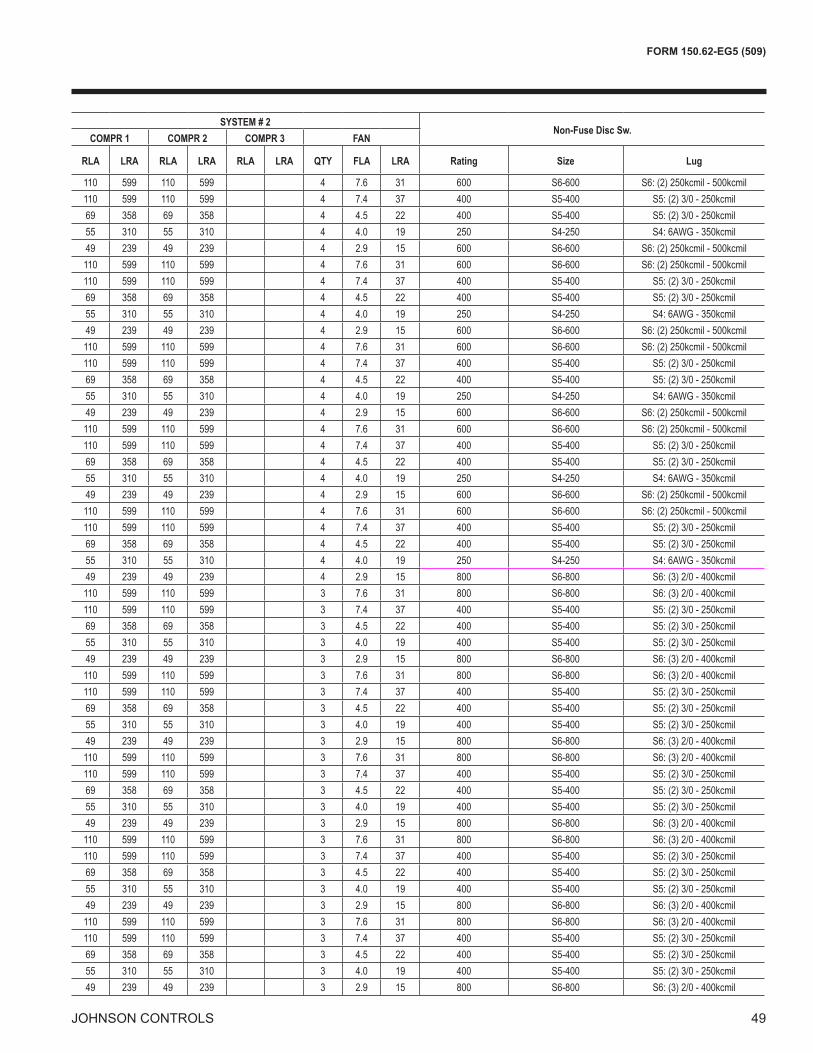
FORM 150.62-EG5 (509)
49jOHNSON CONTROLS
CHILLER MODEL
Pump Model Voltage Pump
FLA MCAMIN N/F DS
MIN DUAL ELEM FUSE
MAX DUAL ELEM FUSE
MAX CB
SYSTEM # 1 SYSTEM # 2Non-Fuse Disc Sw.
COMPR 1 COMPR 2 COMPR 3 FAN COMPR 1 COMPR 2 COMPR 3 FAN
RLA LRA RLA LRA RLA LRA QTY FLA LRA RLA LRA RLA LRA RLA LRA QTY FLA LRA Rating Size Lug
0101 B, F
200 21.4 481 600 600 600 56 425 56 425 56 425 2 7.6 31 110 599 110 599 4 7.6 31 600 S6-600 S6: (2) 250kcmil - 500kcmil230 20.4 479 600 600 600 56 425 56 425 56 425 2 7.4 37 110 599 110 599 4 7.4 37 400 S5-400 S5: (2) 3/0 - 250kcmil380 12 303 400 350 350 36 239 36 239 36 239 2 4.5 22 69 358 69 358 4 4.5 22 400 S5-400 S5: (2) 3/0 - 250kcmil460 10.2 238 400 300 300 27 187 27 187 27 187 2 4.0 19 55 310 55 310 4 4.0 19 250 S4-250 S4: 6AWG - 350kcmil575 8.2 208 250 225 250 24 148 24 148 24 148 2 2.9 15 49 239 49 239 4 2.9 15 600 S6-600 S6: (2) 250kcmil - 500kcmil
0101 D, O
200 41.7 501 600 600 600 56 425 56 425 56 425 2 7.6 31 110 599 110 599 4 7.6 31 600 S6-600 S6: (2) 250kcmil - 500kcmil230 36.3 495 600 600 600 56 425 56 425 56 425 2 7.4 37 110 599 110 599 4 7.4 37 400 S5-400 S5: (2) 3/0 - 250kcmil380 22 313 400 350 350 36 239 36 239 36 239 2 4.5 22 69 358 69 358 4 4.5 22 400 S5-400 S5: (2) 3/0 - 250kcmil460 18.2 246 400 300 300 27 187 27 187 27 187 2 4.0 19 55 310 55 310 4 4.0 19 250 S4-250 S4: 6AWG - 350kcmil575 14.5 214 250 250 250 24 148 24 148 24 148 2 2.9 15 49 239 49 239 4 2.9 15 600 S6-600 S6: (2) 250kcmil - 500kcmil
0101 E, P
200 54.7 514 600 600 600 56 425 56 425 56 425 2 7.6 31 110 599 110 599 4 7.6 31 600 S6-600 S6: (2) 250kcmil - 500kcmil230 49.5 508 600 600 600 56 425 56 425 56 425 2 7.4 37 110 599 110 599 4 7.4 37 400 S5-400 S5: (2) 3/0 - 250kcmil380 29.1 320 400 350 350 36 239 36 239 36 239 2 4.5 22 69 358 69 358 4 4.5 22 400 S5-400 S5: (2) 3/0 - 250kcmil460 24.8 252 400 300 300 27 187 27 187 27 187 2 4.0 19 55 310 55 310 4 4.0 19 250 S4-250 S4: 6AWG - 350kcmil575 19.8 219 250 250 250 24 148 24 148 24 148 2 2.9 15 49 239 49 239 4 2.9 15 600 S6-600 S6: (2) 250kcmil - 500kcmil
0101 K
200 15.4 475 600 600 600 56 425 56 425 56 425 2 7.6 31 110 599 110 599 4 7.6 31 600 S6-600 S6: (2) 250kcmil - 500kcmil230 13.9 472 600 500 500 56 425 56 425 56 425 2 7.4 37 110 599 110 599 4 7.4 37 400 S5-400 S5: (2) 3/0 - 250kcmil380 8.1 299 400 350 350 36 239 36 239 36 239 2 4.5 22 69 358 69 358 4 4.5 22 400 S5-400 S5: (2) 3/0 - 250kcmil460 7 234 400 250 250 27 187 27 187 27 187 2 4.0 19 55 310 55 310 4 4.0 19 250 S4-250 S4: 6AWG - 350kcmil575 5.6 205 250 225 250 24 148 24 148 24 148 2 2.9 15 49 239 49 239 4 2.9 15 600 S6-600 S6: (2) 250kcmil - 500kcmil
0101 L
200 27.1 487 600 600 600 56 425 56 425 56 425 2 7.6 31 110 599 110 599 4 7.6 31 600 S6-600 S6: (2) 250kcmil - 500kcmil230 24.5 483 600 600 600 56 425 56 425 56 425 2 7.4 37 110 599 110 599 4 7.4 37 400 S5-400 S5: (2) 3/0 - 250kcmil380 14.8 306 400 350 350 36 239 36 239 36 239 2 4.5 22 69 358 69 358 4 4.5 22 400 S5-400 S5: (2) 3/0 - 250kcmil460 12.3 240 400 300 300 27 187 27 187 27 187 2 4.0 19 55 310 55 310 4 4.0 19 250 S4-250 S4: 6AWG - 350kcmil575 9.8 209 250 225 250 24 148 24 148 24 148 2 2.9 15 49 239 49 239 4 2.9 15 800 S6-800 S6: (3) 2/0 - 400kcmil
0115 0120 F
200 21.4 532 600 600 600 110 599 110 599 3 7.6 31 110 599 110 599 3 7.6 31 800 S6-800 S6: (3) 2/0 - 400kcmil230 20.4 530 600 600 600 110 599 110 599 3 7.4 37 110 599 110 599 3 7.4 37 400 S5-400 S5: (2) 3/0 - 250kcmil380 12 333 400 400 400 69 358 69 358 3 4.5 22 69 358 69 358 3 4.5 22 400 S5-400 S5: (2) 3/0 - 250kcmil460 10.2 265 400 300 300 55 310 55 310 3 4.0 19 55 310 55 310 3 4.0 19 400 S5-400 S5: (2) 3/0 - 250kcmil575 8.2 235 400 250 250 49 239 49 239 3 2.9 15 49 239 49 239 3 2.9 15 800 S6-800 S6: (3) 2/0 - 400kcmil
0115 0120 C
200 32.2 543 600 600 600 110 599 110 599 3 7.6 31 110 599 110 599 3 7.6 31 800 S6-800 S6: (3) 2/0 - 400kcmil230 28.4 538 600 600 600 110 599 110 599 3 7.4 37 110 599 110 599 3 7.4 37 400 S5-400 S5: (2) 3/0 - 250kcmil380 15.4 336 400 400 400 69 358 69 358 3 4.5 22 69 358 69 358 3 4.5 22 400 S5-400 S5: (2) 3/0 - 250kcmil460 14.2 269 400 300 300 55 310 55 310 3 4.0 19 55 310 55 310 3 4.0 19 400 S5-400 S5: (2) 3/0 - 250kcmil575 11.4 238 400 300 300 49 239 49 239 3 2.9 15 49 239 49 239 3 2.9 15 800 S6-800 S6: (3) 2/0 - 400kcmil
0115 0120* D, M*, O
200 41.7 552 800 600 600 110 599 110 599 3 7.6 31 110 599 110 599 3 7.6 31 800 S6-800 S6: (3) 2/0 - 400kcmil230 36.3 546 600 600 600 110 599 110 599 3 7.4 37 110 599 110 599 3 7.4 37 400 S5-400 S5: (2) 3/0 - 250kcmil380 22 343 400 400 400 69 358 69 358 3 4.5 22 69 358 69 358 3 4.5 22 400 S5-400 S5: (2) 3/0 - 250kcmil460 18.2 273 400 300 300 55 310 55 310 3 4.0 19 55 310 55 310 3 4.0 19 400 S5-400 S5: (2) 3/0 - 250kcmil575 14.5 241 400 300 300 49 239 49 239 3 2.9 15 49 239 49 239 3 2.9 15 800 S6-800 S6: (3) 2/0 - 400kcmil
0115 0120 E, P
200 54.7 565 800 600 600 110 599 110 599 3 7.6 31 110 599 110 599 3 7.6 31 800 S6-800 S6: (3) 2/0 - 400kcmil230 49.5 559 800 600 600 110 599 110 599 3 7.4 37 110 599 110 599 3 7.4 37 400 S5-400 S5: (2) 3/0 - 250kcmil380 29.1 350 400 400 400 69 358 69 358 3 4.5 22 69 358 69 358 3 4.5 22 400 S5-400 S5: (2) 3/0 - 250kcmil460 24.8 280 400 300 300 55 310 55 310 3 4.0 19 55 310 55 310 3 4.0 19 400 S5-400 S5: (2) 3/0 - 250kcmil575 19.8 247 400 300 300 49 239 49 239 3 2.9 15 49 239 49 239 3 2.9 15 800 S6-800 S6: (3) 2/0 - 400kcmil
0115 0120 K
200 15.4 526 600 600 600 110 599 110 599 3 7.6 31 110 599 110 599 3 7.6 31 800 S6-800 S6: (3) 2/0 - 400kcmil230 13.9 523 600 600 600 110 599 110 599 3 7.4 37 110 599 110 599 3 7.4 37 400 S5-400 S5: (2) 3/0 - 250kcmil380 8.1 329 400 350 350 69 358 69 358 3 4.5 22 69 358 69 358 3 4.5 22 400 S5-400 S5: (2) 3/0 - 250kcmil460 7 262 400 300 300 55 310 55 310 3 4.0 19 55 310 55 310 3 4.0 19 400 S5-400 S5: (2) 3/0 - 250kcmil575 5.6 232 400 250 250 49 239 49 239 3 2.9 15 49 239 49 239 3 2.9 15 800 S6-800 S6: (3) 2/0 - 400kcmil

50 jOHNSON CONTROLS
Electrical Data w/ Pumps – continued
CHILLER MODEL
Pump Model Voltage Pump
FLA MCAMIN N/F DS
MIN DUAL ELEM FUSE
MAX DUAL ELEM FUSE
MAX CB
SYSTEM # 1 SYSTEM # 2Non-Fuse Disc Sw.
COMPR 1 COMPR 2 COMPR 3 FAN COMPR 1 COMPR 2 COMPR 3 FAN
RLA LRA RLA LRA RLA LRA QTY FLA LRA RLA LRA RLA LRA RLA LRA QTY FLA LRA Rating Size Lug
0115 L
200 27.1 538 600 600 600 110 599 110 599 3 7.6 31 110 599 110 599 3 7.6 31 800 S6-800 S6: (3) 2/0 - 400kcmil230 24.5 534 600 600 600 110 599 110 599 3 7.4 37 110 599 110 599 3 7.4 37 400 S5-400 S5: (2) 3/0 - 250kcmil380 14.8 336 400 400 400 69 358 69 358 3 4.5 22 69 358 69 358 3 4.5 22 400 S5-400 S5: (2) 3/0 - 250kcmil460 12.3 268 400 300 300 55 310 55 310 3 4.0 19 55 310 55 310 3 4.0 19 400 S5-400 S5: (2) 3/0 - 250kcmil575 9.8 237 400 250 250 49 239 49 239 3 2.9 15 49 239 49 239 3 2.9 15 800 S6-800 S6: (3) 2/0 - 400kcmil
0135 F
200 21.4 604 800 700 700 110 599 110 599 110 599 4 7.6 31 110 599 56 425 4 7.6 31 800 S6-800 S6: (3) 2/0 - 400kcmil230 20.4 601 800 700 700 110 599 110 599 110 599 4 7.4 37 110 599 56 425 4 7.4 37 600 S6-600 S6: (2) 250kcmil - 500kcmil380 12 378 600 400 400 69 358 69 358 69 358 4 4.5 22 69 358 36 239 4 4.5 22 400 S5-400 S5: (2) 3/0 - 250kcmil460 10.2 301 400 350 350 55 310 55 310 55 310 4 4.0 19 55 310 27 187 4 4.0 19 400 S5-400 S5: (2) 3/0 - 250kcmil575 8.2 265 400 300 300 49 239 49 239 49 239 4 2.9 15 49 239 24 148 4 2.9 15 800 S6-800 S6: (3) 2/0 - 400kcmil
0135 C
200 32.2 615 800 700 700 110 599 110 599 110 599 4 7.6 31 110 599 56 425 4 7.6 31 800 S6-800 S6: (3) 2/0 - 400kcmil230 28.4 609 800 700 700 110 599 110 599 110 599 4 7.4 37 110 599 56 425 4 7.4 37 600 S6-600 S6: (2) 250kcmil - 500kcmil380 15.4 382 600 400 450 69 358 69 358 69 358 4 4.5 22 69 358 36 239 4 4.5 22 400 S5-400 S5: (2) 3/0 - 250kcmil460 14.2 305 400 350 350 55 310 55 310 55 310 4 4.0 19 55 310 27 187 4 4.0 19 400 S5-400 S5: (2) 3/0 - 250kcmil575 11.4 268 400 300 300 49 239 49 239 49 239 4 2.9 15 49 239 24 148 4 2.9 15 800 S6-800 S6: (3) 2/0 - 400kcmil
0135 D, M, O
200 41.7 624 800 700 700 110 599 110 599 110 599 4 7.6 31 110 599 56 425 4 7.6 31 800 S6-800 S6: (3) 2/0 - 400kcmil230 36.3 617 800 700 700 110 599 110 599 110 599 4 7.4 37 110 599 56 425 4 7.4 37 600 S6-600 S6: (2) 250kcmil - 500kcmil380 22 388 600 450 450 69 358 69 358 69 358 4 4.5 22 69 358 36 239 4 4.5 22 400 S5-400 S5: (2) 3/0 - 250kcmil460 18.2 309 400 350 350 55 310 55 310 55 310 4 4.0 19 55 310 27 187 4 4.0 19 400 S5-400 S5: (2) 3/0 - 250kcmil575 14.5 271 400 300 300 49 239 49 239 49 239 4 2.9 15 49 239 24 148 4 2.9 15 800 S6-800 S6: (3) 2/0 - 400kcmil
0135 E, R
200 54.7 637 800 700 700 110 599 110 599 110 599 4 7.6 31 110 599 56 425 4 7.6 31 800 S6-800 S6: (3) 2/0 - 400kcmil230 49.5 630 800 700 700 110 599 110 599 110 599 4 7.4 37 110 599 56 425 4 7.4 37 600 S6-600 S6: (2) 250kcmil - 500kcmil380 29.1 395 600 450 450 69 358 69 358 69 358 4 4.5 22 69 358 36 239 4 4.5 22 400 S5-400 S5: (2) 3/0 - 250kcmil460 24.8 315 400 350 350 55 310 55 310 55 310 4 4.0 19 55 310 27 187 4 4.0 19 400 S5-400 S5: (2) 3/0 - 250kcmil575 19.8 277 400 300 300 49 239 49 239 49 239 4 2.9 15 49 239 24 148 4 2.9 15 800 S6-800 S6: (3) 2/0 - 400kcmil
0135 K
200 15.4 598 800 700 700 110 599 110 599 110 599 4 7.6 31 110 599 56 425 4 7.6 31 800 S6-800 S6: (3) 2/0 - 400kcmil230 13.9 595 800 700 700 110 599 110 599 110 599 4 7.4 37 110 599 56 425 4 7.4 37 600 S6-600 S6: (2) 250kcmil - 500kcmil380 8.1 374 600 400 400 69 358 69 358 69 358 4 4.5 22 69 358 36 239 4 4.5 22 400 S5-400 S5: (2) 3/0 - 250kcmil460 7 297 400 350 350 55 310 55 310 55 310 4 4.0 19 55 310 27 187 4 4.0 19 400 S5-400 S5: (2) 3/0 - 250kcmil575 5.6 262 400 300 300 49 239 49 239 49 239 4 2.9 15 49 239 24 148 4 2.9 15 800 S6-800 S6: (3) 2/0 - 400kcmil
0150 0155 G
200 32.2 668 800 700 700 110 599 110 599 110 599 4 7.6 31 110 599 110 599 4 7.6 31 800 S6-800 S6: (3) 2/0 - 400kcmil230 28.4 663 800 700 700 110 599 110 599 110 599 4 7.4 37 110 599 110 599 4 7.4 37 600 S6-600 S6: (2) 250kcmil - 500kcmil380 15.4 414 600 450 450 69 358 69 358 69 358 4 4.5 22 69 358 69 358 4 4.5 22 400 S5-400 S5: (2) 3/0 - 250kcmil460 14.2 332 400 350 350 55 310 55 310 55 310 4 4.0 19 55 310 55 310 4 4.0 19 400 S5-400 S5: (2) 3/0 - 250kcmil575 11.4 294 400 350 350 49 239 49 239 49 239 4 2.9 15 49 239 49 239 4 2.9 15 800 S6-800 S6: (3) 2/0 - 400kcmil
0150 0155 H, L
200 27.1 663 800 700 700 110 599 110 599 110 599 4 7.6 31 110 599 110 599 4 7.6 31 800 S6-800 S6: (3) 2/0 - 400kcmil230 24.5 659 800 700 700 110 599 110 599 110 599 4 7.4 37 110 599 110 599 4 7.4 37 600 S6-600 S6: (2) 250kcmil - 500kcmil380 14.8 414 600 450 450 69 358 69 358 69 358 4 4.5 22 69 358 69 358 4 4.5 22 400 S5-400 S5: (2) 3/0 - 250kcmil460 12.3 330 400 350 350 55 310 55 310 55 310 4 4.0 19 55 310 55 310 4 4.0 19 400 S5-400 S5: (2) 3/0 - 250kcmil575 9.8 292 400 350 350 49 239 49 239 49 239 4 2.9 15 49 239 49 239 4 2.9 15 800 S6-800 S6: (3) 2/0 - 400kcmil
0150 0155 I, M
200 41.7 678 800 800 800 110 599 110 599 110 599 4 7.6 31 110 599 110 599 4 7.6 31 800 S6-800 S6: (3) 2/0 - 400kcmil230 36.3 671 800 700 700 110 599 110 599 110 599 4 7.4 37 110 599 110 599 4 7.4 37 600 S6-600 S6: (2) 250kcmil - 500kcmil380 22 421 600 450 450 69 358 69 358 69 358 4 4.5 22 69 358 69 358 4 4.5 22 400 S5-400 S5: (2) 3/0 - 250kcmil460 18.2 336 400 350 350 55 310 55 310 55 310 4 4.0 19 55 310 55 310 4 4.0 19 400 S5-400 S5: (2) 3/0 - 250kcmil575 14.5 297 400 350 350 49 239 49 239 49 239 4 2.9 15 49 239 49 239 4 2.9 15 800 S6-800 S6: (3) 2/0 - 400kcmil
0150 0155 J, R
200 54.7 691 800 800 800 110 599 110 599 110 599 4 7.6 31 110 599 110 599 4 7.6 31 800 S6-800 S6: (3) 2/0 - 400kcmil230 49.5 684 800 800 800 110 599 110 599 110 599 4 7.4 37 110 599 110 599 4 7.4 37 600 S6-600 S6: (2) 250kcmil - 500kcmil380 29.1 428 600 450 450 69 358 69 358 69 358 4 4.5 22 69 358 69 358 4 4.5 22 400 S5-400 S5: (2) 3/0 - 250kcmil460 24.8 343 400 400 400 55 310 55 310 55 310 4 4.0 19 55 310 55 310 4 4.0 19 400 S5-400 S5: (2) 3/0 - 250kcmil575 19.8 302 400 350 350 49 239 49 239 49 239 4 2.9 15 49 239 49 239 4 2.9 15 1000 S7-1000 S7-1200: (4) 4/0 - 500kcmil

FORM 150.62-EG5 (509)
51jOHNSON CONTROLS
CHILLER MODEL
Pump Model Voltage Pump
FLA MCAMIN N/F DS
MIN DUAL ELEM FUSE
MAX DUAL ELEM FUSE
MAX CB
SYSTEM # 1 SYSTEM # 2Non-Fuse Disc Sw.
COMPR 1 COMPR 2 COMPR 3 FAN COMPR 1 COMPR 2 COMPR 3 FAN
RLA LRA RLA LRA RLA LRA QTY FLA LRA RLA LRA RLA LRA RLA LRA QTY FLA LRA Rating Size Lug
0115 L
200 27.1 538 600 600 600 110 599 110 599 3 7.6 31 110 599 110 599 3 7.6 31 800 S6-800 S6: (3) 2/0 - 400kcmil230 24.5 534 600 600 600 110 599 110 599 3 7.4 37 110 599 110 599 3 7.4 37 400 S5-400 S5: (2) 3/0 - 250kcmil380 14.8 336 400 400 400 69 358 69 358 3 4.5 22 69 358 69 358 3 4.5 22 400 S5-400 S5: (2) 3/0 - 250kcmil460 12.3 268 400 300 300 55 310 55 310 3 4.0 19 55 310 55 310 3 4.0 19 400 S5-400 S5: (2) 3/0 - 250kcmil575 9.8 237 400 250 250 49 239 49 239 3 2.9 15 49 239 49 239 3 2.9 15 800 S6-800 S6: (3) 2/0 - 400kcmil
0135 F
200 21.4 604 800 700 700 110 599 110 599 110 599 4 7.6 31 110 599 56 425 4 7.6 31 800 S6-800 S6: (3) 2/0 - 400kcmil230 20.4 601 800 700 700 110 599 110 599 110 599 4 7.4 37 110 599 56 425 4 7.4 37 600 S6-600 S6: (2) 250kcmil - 500kcmil380 12 378 600 400 400 69 358 69 358 69 358 4 4.5 22 69 358 36 239 4 4.5 22 400 S5-400 S5: (2) 3/0 - 250kcmil460 10.2 301 400 350 350 55 310 55 310 55 310 4 4.0 19 55 310 27 187 4 4.0 19 400 S5-400 S5: (2) 3/0 - 250kcmil575 8.2 265 400 300 300 49 239 49 239 49 239 4 2.9 15 49 239 24 148 4 2.9 15 800 S6-800 S6: (3) 2/0 - 400kcmil
0135 C
200 32.2 615 800 700 700 110 599 110 599 110 599 4 7.6 31 110 599 56 425 4 7.6 31 800 S6-800 S6: (3) 2/0 - 400kcmil230 28.4 609 800 700 700 110 599 110 599 110 599 4 7.4 37 110 599 56 425 4 7.4 37 600 S6-600 S6: (2) 250kcmil - 500kcmil380 15.4 382 600 400 450 69 358 69 358 69 358 4 4.5 22 69 358 36 239 4 4.5 22 400 S5-400 S5: (2) 3/0 - 250kcmil460 14.2 305 400 350 350 55 310 55 310 55 310 4 4.0 19 55 310 27 187 4 4.0 19 400 S5-400 S5: (2) 3/0 - 250kcmil575 11.4 268 400 300 300 49 239 49 239 49 239 4 2.9 15 49 239 24 148 4 2.9 15 800 S6-800 S6: (3) 2/0 - 400kcmil
0135 D, M, O
200 41.7 624 800 700 700 110 599 110 599 110 599 4 7.6 31 110 599 56 425 4 7.6 31 800 S6-800 S6: (3) 2/0 - 400kcmil230 36.3 617 800 700 700 110 599 110 599 110 599 4 7.4 37 110 599 56 425 4 7.4 37 600 S6-600 S6: (2) 250kcmil - 500kcmil380 22 388 600 450 450 69 358 69 358 69 358 4 4.5 22 69 358 36 239 4 4.5 22 400 S5-400 S5: (2) 3/0 - 250kcmil460 18.2 309 400 350 350 55 310 55 310 55 310 4 4.0 19 55 310 27 187 4 4.0 19 400 S5-400 S5: (2) 3/0 - 250kcmil575 14.5 271 400 300 300 49 239 49 239 49 239 4 2.9 15 49 239 24 148 4 2.9 15 800 S6-800 S6: (3) 2/0 - 400kcmil
0135 E, R
200 54.7 637 800 700 700 110 599 110 599 110 599 4 7.6 31 110 599 56 425 4 7.6 31 800 S6-800 S6: (3) 2/0 - 400kcmil230 49.5 630 800 700 700 110 599 110 599 110 599 4 7.4 37 110 599 56 425 4 7.4 37 600 S6-600 S6: (2) 250kcmil - 500kcmil380 29.1 395 600 450 450 69 358 69 358 69 358 4 4.5 22 69 358 36 239 4 4.5 22 400 S5-400 S5: (2) 3/0 - 250kcmil460 24.8 315 400 350 350 55 310 55 310 55 310 4 4.0 19 55 310 27 187 4 4.0 19 400 S5-400 S5: (2) 3/0 - 250kcmil575 19.8 277 400 300 300 49 239 49 239 49 239 4 2.9 15 49 239 24 148 4 2.9 15 800 S6-800 S6: (3) 2/0 - 400kcmil
0135 K
200 15.4 598 800 700 700 110 599 110 599 110 599 4 7.6 31 110 599 56 425 4 7.6 31 800 S6-800 S6: (3) 2/0 - 400kcmil230 13.9 595 800 700 700 110 599 110 599 110 599 4 7.4 37 110 599 56 425 4 7.4 37 600 S6-600 S6: (2) 250kcmil - 500kcmil380 8.1 374 600 400 400 69 358 69 358 69 358 4 4.5 22 69 358 36 239 4 4.5 22 400 S5-400 S5: (2) 3/0 - 250kcmil460 7 297 400 350 350 55 310 55 310 55 310 4 4.0 19 55 310 27 187 4 4.0 19 400 S5-400 S5: (2) 3/0 - 250kcmil575 5.6 262 400 300 300 49 239 49 239 49 239 4 2.9 15 49 239 24 148 4 2.9 15 800 S6-800 S6: (3) 2/0 - 400kcmil
0150 0155 G
200 32.2 668 800 700 700 110 599 110 599 110 599 4 7.6 31 110 599 110 599 4 7.6 31 800 S6-800 S6: (3) 2/0 - 400kcmil230 28.4 663 800 700 700 110 599 110 599 110 599 4 7.4 37 110 599 110 599 4 7.4 37 600 S6-600 S6: (2) 250kcmil - 500kcmil380 15.4 414 600 450 450 69 358 69 358 69 358 4 4.5 22 69 358 69 358 4 4.5 22 400 S5-400 S5: (2) 3/0 - 250kcmil460 14.2 332 400 350 350 55 310 55 310 55 310 4 4.0 19 55 310 55 310 4 4.0 19 400 S5-400 S5: (2) 3/0 - 250kcmil575 11.4 294 400 350 350 49 239 49 239 49 239 4 2.9 15 49 239 49 239 4 2.9 15 800 S6-800 S6: (3) 2/0 - 400kcmil
0150 0155 H, L
200 27.1 663 800 700 700 110 599 110 599 110 599 4 7.6 31 110 599 110 599 4 7.6 31 800 S6-800 S6: (3) 2/0 - 400kcmil230 24.5 659 800 700 700 110 599 110 599 110 599 4 7.4 37 110 599 110 599 4 7.4 37 600 S6-600 S6: (2) 250kcmil - 500kcmil380 14.8 414 600 450 450 69 358 69 358 69 358 4 4.5 22 69 358 69 358 4 4.5 22 400 S5-400 S5: (2) 3/0 - 250kcmil460 12.3 330 400 350 350 55 310 55 310 55 310 4 4.0 19 55 310 55 310 4 4.0 19 400 S5-400 S5: (2) 3/0 - 250kcmil575 9.8 292 400 350 350 49 239 49 239 49 239 4 2.9 15 49 239 49 239 4 2.9 15 800 S6-800 S6: (3) 2/0 - 400kcmil
0150 0155 I, M
200 41.7 678 800 800 800 110 599 110 599 110 599 4 7.6 31 110 599 110 599 4 7.6 31 800 S6-800 S6: (3) 2/0 - 400kcmil230 36.3 671 800 700 700 110 599 110 599 110 599 4 7.4 37 110 599 110 599 4 7.4 37 600 S6-600 S6: (2) 250kcmil - 500kcmil380 22 421 600 450 450 69 358 69 358 69 358 4 4.5 22 69 358 69 358 4 4.5 22 400 S5-400 S5: (2) 3/0 - 250kcmil460 18.2 336 400 350 350 55 310 55 310 55 310 4 4.0 19 55 310 55 310 4 4.0 19 400 S5-400 S5: (2) 3/0 - 250kcmil575 14.5 297 400 350 350 49 239 49 239 49 239 4 2.9 15 49 239 49 239 4 2.9 15 800 S6-800 S6: (3) 2/0 - 400kcmil
0150 0155 J, R
200 54.7 691 800 800 800 110 599 110 599 110 599 4 7.6 31 110 599 110 599 4 7.6 31 800 S6-800 S6: (3) 2/0 - 400kcmil230 49.5 684 800 800 800 110 599 110 599 110 599 4 7.4 37 110 599 110 599 4 7.4 37 600 S6-600 S6: (2) 250kcmil - 500kcmil380 29.1 428 600 450 450 69 358 69 358 69 358 4 4.5 22 69 358 69 358 4 4.5 22 400 S5-400 S5: (2) 3/0 - 250kcmil460 24.8 343 400 400 400 55 310 55 310 55 310 4 4.0 19 55 310 55 310 4 4.0 19 400 S5-400 S5: (2) 3/0 - 250kcmil575 19.8 302 400 350 350 49 239 49 239 49 239 4 2.9 15 49 239 49 239 4 2.9 15 1000 S7-1000 S7-1200: (4) 4/0 - 500kcmil

5� jOHNSON CONTROLS
Wiring Diagram

FORM 150.62-EG5 (509)
5�jOHNSON CONTROLS
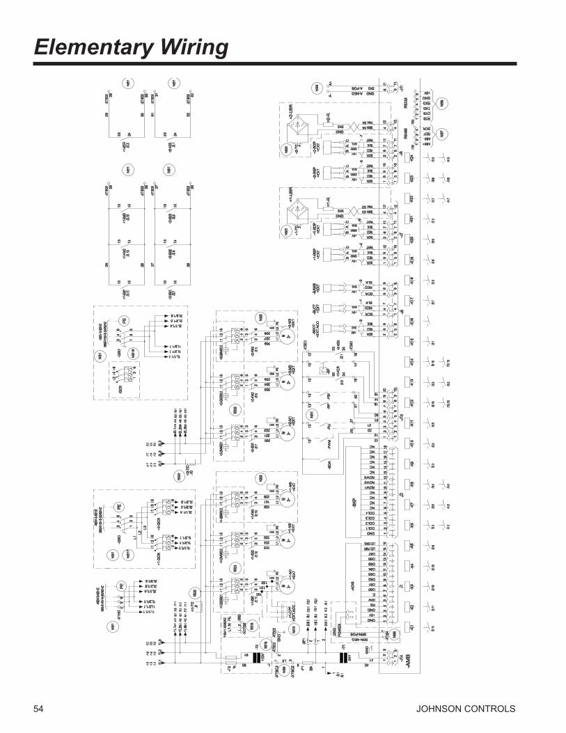
54 jOHNSON CONTROLS
/2.1
/5.1
/3.6
/13.1
/9.2
/4.6
/3.6
/13.1
/9.2
/4.6
/3.6
/13.1
/9.2
/4.6
/1.2
/1.6
/1.3
/1.2
/1.6
/1.3
/1.2
/1.7
/1.3
/1.2
/1.7
/1.4
/1.2
/1.7
/1.4
/1.2
/1.7
/1.4
/3.1
/11.1
/7.2
/5.1
/4.2
/3.1
/11.1
/7.2
/5.1
/4.2
/3.1
/11.1
/7.2
/5.1
/4.2
/5.1
/4.2
/3.2
/2.1
/12.1
/10.1
/8.1
/6.1
/12.1
/10.1
/8.1
/6.1
NB
1N
B1
NB
1N
B1
RS
485
RS
232
485+485-REFSCR
RTSCTSTXDRXDGND+5V
NB10
NB
2
PE
PE
NB
2
NB
7N
B8
-AM
B
NB
6
GN
DP
OW
ER
NB
1
+5V
SIG
+5V
+5V
SIG
SIG
GND
GND
+5V
SIG
+5V
SIG
GNDSIG
+5V
+5V
SIG
SIG
GND
GND
NB
5
GNDSIG
NB
1N
B1
NB
17
GNDSIG
PE
NB
1
NB
16
NB
9
115V
-1-5
0/60
HZ PE
NL1
460V
-3-6
0HZ
380/
415V
-3-5
0/60
HZ
460V
-3-6
0HZ
380/
415V
-3-5
0/60
HZ46
0V-3
-60H
Z38
0/41
5V-3
-50/
60HZ
NB18
NB18
NB20
NB20
NB23
NB23
NB20
NB20
.9.1
0
/2.11
/2.1
0/2
.10
/2.7
/2.6
/2.5
/2.2 /2.1
/2.1
/2.2
/2.11
/2.1
0/2
.10
/2.6
/2.5
/2.7
/2.11
/2.11
/2.10
/2.10
/2.9
/3.2
/3.3
/3.4
/2.3
/2.2
/2.2
/5.3
/6.10
/2.1
/2.7
/2.6
/2.6
/2.5
/8.10
/3.7
/3.8
/3.9
/2.5
/5.2
/10.10
/4.3
/4.3
/4.4
/4.7
/4.8
/4.9
/12.10
.4.2
COL2COL1GND
NC
NCNC
ROW3
NCNC
NC
ROW2ROW1NCNCNCNCCOL4COL3
118
1716
1510
1413
1211
98
7
J2
65
43
2
-SK
P
J1
1615
1413
1211
106
54
32
19
8
LED PWRDB7DB6DB5DB4DB3DB2DB1DB0ER/WRSGND+5VGND
7
LED GND
M 3~M 3~
M 3~M 3~
24V
110V
M 3~M 3~
20A?A
12
104
38
65
9
12
34
56
98
10
SCR
REDBLK
12
14
7
BA
CB
AC
15
910
26
711
REDBLKWHT
SCR
REDBLKWHT
SCR
71
59
102
67
111
48
52
12
3
12
3
1
BA
CB
AC
51
910
26
711
REDBLKWHT
SCR
REDBLKWHT
SCR
15
910
27
116
BLKREDSCR
25
8
12
7 7
PEL3
L2L1
PEL3
L2L1
PEL3
L2L1
PEL3
L2L1
P2 S2
P1 S1
P2 S2
P1 S1
116
116
32
1
L
56
34
12
PEL3
L2L1
21
21
1
PEL3
L2L1
-+
33SCR
21 6
996
BLKRED
65
43
21
65
43
21
5
412
412
412
412
PNK
PNK
BRN
BRN
21
21
L1o
L1i
LGN
D
1413
1413
1413
1413
1413
1413
2423 2423
3433
3433
65
43
21
65
43
21
65
43
21
65
43
21
65
43
21
65
43
21
2 1
L2o
L2i
L1o
L1i
UV
W
65
43
21
65
43
21
65
43
21
65
43
21
65
43
21
65
43
21
25 26 27 28
12
34
12
34
56
1313
1313
1313
13
A+
A-
2
2
5150
1918
14
GN
D
29 30 31 32
2120
S2 S1
S2 S1
11
11
11
56
34
12
56
34
12
-K1
-K2
-K3
-K4
-K5
-J13
+EX
T-B
LCT
+EX
T=1
-BS
P+E
XT
=1-B
DP
-1-4
-6
-J7
-J6
-K6
-K7
-K8
-K9
-K10
-K13
-K11
-K12
-K15
-K17
-K18
-K19
-K20
-K16
-K14
-K22
-K23
-K24
-K21
-J14
+EX
T=2
-BS
P+E
XT
=2-B
DP
-5-7
-J9
-SF
-3
+EX
T.A
CC
-BE
CT
-AD
IS
+EX
T=1
-M1
+EX
T=1
-M2
+EX
T=2
-M1
+EX
T=2
-M2
-T1
-T2
-J11
+EX
T.A
CC
=1-C
PF
-XTB
C2
1
-QS
D
+EX
T=2
-M3
-SO
A-R
U-R
P-P
WM
+EX
T=1
-M3
-XTB
4
2L1
2L2
2L3
-2
+EX
T-B
AM
B
=1-Q
CB
=2-Q
CB
1L1
1L1/1.1
1L1/1.1
1L1/1.1
1L2
1L3
2L1
2L2
2L3
1L2/1.11L3/1.1
2L1/1.42L2/1.52L3/1.5
1L2/1.11L3/1.1
2L1/1.42L2/1.52L3/1.5
1L2/1.11L3/1.1
2L1/1.42L2/1.52L3/1.5
1L1
1L2
1L3
-XTB
C2
=1-R
=2-R
=1-U
BR
=2-U
BR
=1-T
C=2
-TC
-F1
-XC
TB2 2
=1-K
M1
=1-K
M2
=1-K
M3
=2-K
M1
=2-K
M2
=2-K
M3
=1-K
CR
=2-K
CR
=2-K
CR=1
-KCR
=1-K
M1
=1-K
M2
=1-K
M3
=2-K
M2
=2-K
M3
=2-K
M1
-XP1
2 1
-F3
-XTB
C
=1-Q
MMSC
1=1
-QMM
SC2
=1-Q
MMSC
3=2
-QMM
SC2
=2-Q
MMSC
3=2
-QMM
SC1
-XTB
C2
-XTB
C2
-XTB
C2
-XTB
C2
-TB1
-TB3
-XTB
C1
-XTB
C2
-XTB
C1
-XTB
C2
-XTB
C2
-XTB
C2
-XTB
C2
-XTB
C2
=2-T
C=1
-TC
-QC
B-Q
SD
-FS
I
28272625
103104105
106107108
102101
100
200201202
203204205
206207208
GN
D
50
A-NEGA-POS
4041
LLK
5352
5554
5
51
181419
1312
BRN-POSBRN-NEG
90
91
L1L2
L3
29 30 31 32
2120
21
GND
GND
GND
GND
GND
GND
Elementary Wiring

FORM 150.62-EG5 (509)
55jOHNSON CONTROLS
/3.5/4.5
/3.9/4.9
/5.3
/10.9/6.9
NB
3
NB
2
-AM
B
NB
3
NB11
NB
2
NB
1
NB
19N
B2
NB
2
NB
2
NB
11N
B11
NB
11N
B11
NB
11N
B11
NB
4
/1.9/1.5
/1.7/1.8
/1.6/1.8
.2
/1.1/1.2
/1.2/1.3
.1
/1.7/1.8
/1.3/1.4
.10.11
.10.7
.6.5
.4.8 .8
.4.3.7
/1.10.7/1.6
.1.1
.1
/1.10.11/1.6
.9 /1.2/1.2/1.2
/1.8.9 /1.3/1.3/1.3
/1.8.7 /1.4/1.4/1.4
/1.9
.2.2
.2
.4 /1.7/1.7/1.7
/1.9.5 /1.5/1.5/1.5
/1.8.5 /1.6/1.6/1.6
/1.8
3
1
P>
3
1
P>
3
1
P>
3
1
P>
2E
1
2E
1
2E
1
>> >
>>>
15A
S2
S1
S2
S1
S2
S1
S2
S1
S2
S1
S2
S1
4443
3433 13
2423
14
4443
3433 13
2423
14
2221
2
13
65 1
43
14
2221
2
13
65 1
43
14
2221
2
13
65 1
43
14
2221
2
13
65 1
43
14
2221
2
13
65 1
43
14
2221
2
13
65 1
43
14
2 1
2 1
1
3 1
3
1
3 1
3
2 1
2 1
2 1
2 1
2 112
41
1
4
21
76
32
17
65
43
21
76
54
32
1
2 1
1
4
14 13
14 13
22 21
22 21
22 21
22 21
22 21
22 21
A2 A1
A2 A1
A2 A1
A2 A1
A2 A1
A2 A1
A2 A1
A2 A1
M2
M1
M2
M1
M2
M1
M2
M1
M2
M1
M2
M1
L1o
L1i
131231
2324
235135
133
132 139
233
232 239
134234
22
22
22
120125
124126
123
2
225224
226
140
220
2
11
11
T2 T1
T2 T1
T2 T1
T2 T1
T2 T1
T2 T1
PE
2 1
11
PE
2 1
+EXT=2-ECH1
+EX
T=2-ECH2
+EX
T=1-FH
P2
+EX
T=1-FH
P1
+EX
T=2-FH
P2
+EX
T=2-FH
P1
+EX
T=2-ECH3
+EX
T=1-ECH2
+EX
T=1-ECH1
+EX
T=1-ECH3
1/1.12/1.1
+EX
T=2-YLLSV
+EX
T=1-YLLSV
-XTB9-XTB8
-XTB10-XTB7
XY
+EX
T=1-YHGSV
V
-K21-K10
-K15-K20
-K13-K19
=1-KCR
-K1-K2
-K3-K5
=2-KCR
-K17-K18
-K4-K9
=1-KM2
=1-KM1
=1-KM3
=2-KM1
=2-KM2
=2-KM3
=2-KM3
=2-KM2
=1-KM1
=1-KM2
=2-KM1
=1-KM3
=2-KCR=1-KCR
+EXT=2-BM
P2+EXT
=1-BMP2
+EXT=1-BM
P1+EXT
=2-BMP1
+EXT=2-BM
P3+EXT
=1-BMP3
-F2
=1-XTBF=2-XTBF
-XTBC2-XTBC2
=2-XTBF=1-XTBF
=1-XTBF
=1-XTBF
=1-XTBF
=2-XTBF
=2-XTBF
=2-XTBF
=1-XTBF=2-XTBF
=1-XTBF=1-XTBF
=2-XTBF=2-XTBF
=2-XTBF-XTBC2
=1-XTBF=1-XTBF
=1-XTBF=1-XTBF
-XTBC2
-XTBC2
=2-XTBF=2-XTBF
=2-XTBF
-XTBC2
=2-XTBF
=1-XTBF
=1-XTBF=1-XTBF
=2-XTBF=2-XTBF
+EX
T=2-BM
P3+E
XT
=2-BMP2
+EX
T=2-BM
P1+E
XT
=1-BMP3
+EX
T=1-BM
P2+E
XT
=1-BMP1
+EXT-EEH
+EXT-EPH
235 234 233 232239
231
24
23
135 133 132139
131
140 136
226
225 225
224
125
GND
118
2
1
119
121
123
120
134
124
122
221
222
GND
219
126
218
220
GND
GND
GND

56 jOHNSON CONTROLS
=1-M
F1
=1-M
F2
=1-M
F1
=1-M
F2
=1-M
F1
=1-M
F1=1
-MF2
=1-M
F3=1
-MF4
=1-M
F1=1
-MF2
=1-M
F3=1
-MF4
=2-M
F1=2
-MF2
=2-M
F3=2
-MF4
=2-M
F5
=2-M
F1=2
-MF1
=2-M
F2
=2-M
F1=2
-MF2
=2-M
F3=2
-MF4
=2-M
F1=2
-MF2
=2-M
F3=2
-MF4
=1-M
F5
=2-M
F3=2
-MF2
=1-M
F3=1
-MF2
=1-M
F1=1
-MF2
=1-M
F3=1
-MF4
=1M
F5
=1-M
F1
=1-M
F2=2
-MF1
=2-M
F2
=2-M
F3
=2-M
F1
=1-M
F1=1
-MF2
=2-M
F1=2
-MF2
=2-M
F3=2
-MF4
=1-M
F4=1
-MF5
=2-M
F3=2
-MF2
=1-M
F3
=1-M
F6
YLA
A01
00S
EY
LAA
0101
HE
YLA
A00
91H
EY
LAA
0115
SE
YLA
A01
20S
E
YLA
A01
25H
EY
LAA
0135
SE
YLA
A01
50S
EY
LAA
0155
SE
YLA
A01
41H
E
YLA
A01
75H
EY
LAA
0156
HE
YLA
A00
70S
EY
LAA
0071
HE
YLA
A00
80S
EY
LAA
0090
SE
NB
12N
B21
NB
22 NB
22
NB
12
NB
13
NB
14
NB
15
NB
15
NB
12N
B14
NB
15
NB
25
NB
26
NB
21N
B14
NB
27
NB
27
GN
D
150
151
152
T3T1 T2
GN
D
153
154
155
T3T1 T2
GN
D
T3T1 T2
156
157
158
GN
D
250
251
252
T3T1 T2
GN
D
253
254
255
T3T1 T2
GN
D
T3T1 T2
256
257
258
GN
D
150
151
152
T3T1 T2
GN
D
T3T1 T2
153
154
155
GN
D
153A
154A
155A
T3T1 T2
GN
D
T3T1 T2
156
157
158
GN
D
T3T1 T2
156A
156B 15
7A15
7B 158A
158B
GN
D
250
251
252
T3T1 T2
GN
D
T3T1 T2
253
254
255
GN
D
253A
254A
255A
T3T1 T2
GN
D
T3T1 T2
256
257
258
GN
D
T3T1 T2
256A
257A
258A
GN
D
156B
157B
158B
T3T1 T2
503A
505A
502
501
500
GN
D
504A
1
52
64
3
GND
505A
504A
500
501
502
503A
509A
511A
508
507
506
GN
D
510A
1
52
64
3
GND
511A
510A
506
507
508
509A
515A
517A
514
513
512
GN
D
516A
1
52
64
3
GND
517A
516A
512
513
514
515A
521A
523A
520
519
518
GN
D
522A
1
52
64
3
GND
523A
522A
518
519
520
521A
527A
529A
526
525
524
GN
D
528A
1
52
64
3
GND
529A
528A
524
525
526
527A
563A
565A
562
561
560
GN
D
564A
1
52
64
3
GND
565A
564A
560
561
562
563A
533A
535A
532
531
530
GN
D
534A
1
52
64
3
GND
535A
534A
530
531
532
533A
539A
541A
538
537
536
GN
D
540A
1
52
64
3
GND
541A
540A
536
537
538
539A
545A
547A
544
543
542
GN
D
546A
1
52
64
3
GND
547A
546A
542
543
544
545A
551A
553A
550
549
548
GN
D
552A
1
52
64
3
GND
553A
552A
548
549
550
551A
557A
559A
556
555
554
GN
D
558A
1
52
64
3
GND
559A
558A
554
555
556
557A
GN
D
156A
157A
158A
T3T1 T2
GN
D
256A
257A
258A
T3T1 T2
PE
U1V1
W1
W2
U2V2
PE
U1V1
W1
W2
U2V2
PE
U1V1
W1
W2
U2V2
PE
U1V1
W1
W2
U2V2
PE
U1V1
W1
W2
U2V2
PE
U1V1
W1
W2
U2V2
PE
U1V1
W1
W2
U2V2
PE
U1V1
W1
W2
U2V2
PE
U1V1
W1
W2
U2V2
PE
U1V1
W1
W2
U2V2
PE
U1V1
W1
W2
U2V2
=1-M
F1+E
XT
=1-M
F2+E
XT
=1-M
F3+E
XT
=2-M
F1+E
XT
=2-M
F2+E
XT
=2-M
F3+E
XT
=1-M
F1+E
XT
=1-M
F2+E
XT
=1-M
F3+E
XT
=1-M
F4+E
XT
=1-M
F5+E
XT
=2-M
F1+E
XT
=2-M
F2+E
XT
=2-M
F3+E
XT
=2-M
F4+E
XT
=2-M
F5+E
XT
=1-M
F6+E
XT
=1-M
F1+E
XT
=1-M
F1+E
XT
=1-M
F2+E
XT
=1-M
F2+E
XT
=1-M
F3+E
XT
=1-M
F3+E
XT
=1-M
F4+E
XT
=1-M
F4+E
XT
=1-M
F5+E
XT
=1-M
F5+E
XT
=1-M
F6+E
XT
=1-M
F6+E
XT
=2-M
F1+E
XT
=2-M
F1+E
XT
=2-M
F2+E
XT
=2-M
F2+E
XT
=2-M
F3+E
XT
=2-M
F3+E
XT
=2-M
F4+E
XT
=2-M
F4+E
XT
=2-M
F5+E
XT
=2-M
F5+E
XT
=1-M
F4+E
XT
=2-M
F4+E
XT
Condenser Fan Mapping and Sequencing

FORM 150.62-EG5 (509)
57jOHNSON CONTROLS
-BE
CT
-BLC
T
=1-Y
LLS
V
=1-B
SP
=2-B
SP
=1-Z
CPR1
=1-Z
CPR2
=1-Z
CPR3
=2-Z
CPR1
=2-Z
CPR3
=2-Y
LLS
V
=2-F
HP
1
=2-F
HP
2=1
-FH
P1
=1-F
HP
2
=2-Z
CPR2
=2-B
DP
=2-B
HP
NB
2N
B2
NB11
NB11
NB11
NB11
NB11
NB11
NB
3
NB
3
NB
19
139
131A
132
139A
239A
231A
232
239A
GN
D
208
207
206
220
GN
D
E
2AH
2AG
120
GN
D
E
GN
D
205
204
203
GN
D
105
104
103
GN
D
202
201
200
GN
D
108
107
106
124A 2A
J 2
125A
22A
K
126A
22A
N
224A 2A
L 2
225A
22A
M
226A 2A
P 2
GN
D
102
101
100 13
3
1AA2
132A
S2
S1
134
1AB2
133A
S2
S1
135A1A
E
134A
S2
S1
2
233
1AL2
232A
S2
S1
234
1AM2
233A
S2
S1
235A1A
F2
234A
S2
S1
GN
D30
130
230
0G
ND
304
305
303
140A GN
D
2AQ
140B GN
D
2AR
23
1
23
1
23
1
23
1
PE
L3
L2
L1
4
23
1
4
23
1
PE
L3
L2
L1
PE
L3
L2
L1
PE
L3
L2
L1
PE
L3
L2
L1
21
21
21
21
21
21
PE
L3
L2
L1 M1
M2
T1T2
M1
M2
T1T2
M1
M2
T1T2
M1
M2
T1T2
M1
M2
T1T2
M1
M2
T1T2
EW
1V
1U
1
V2
U2
W2
EW
1V
1U
1
V2
U2
W2
PE
21
PE
21
=1-F
HP
1+E
XT
=1-F
HP
2+E
XT
=2-F
HP
1+E
XT
=2-F
HP
2+E
XT
=2-M
3+E
XT
=2-Y
LLS
V+E
XT
=1-Y
LLS
V+E
XT
=2-M
2+E
XT
=1-M
2+E
XT
=2-M
1+E
XT
=1-M
3+E
XT
=1-E
CH
1+E
XT
=1-E
CH
2+E
XT
=1-E
CH
3+E
XT
=2-E
CH
1+E
XT
=2-E
CH
2+E
XT
=2-E
CH
3+E
XT
=1-M
1+E
XT
=1-B
MP1
+EXT
=1-B
MP2
+EXT
=1-B
MP3
+EXT
=2-B
MP1
+EXT
=2-B
MP2
+EXT
=2-B
MP3
+EXT
-MP1
+PUM
P
-MP2
+PUM
P
-EE
H+E
XT
-EP
H+E
XT
Compressor Wiring

58 jOHNSON CONTROLS
NB
16N
B17
NB
19
1L1
1L2
1L3
2L1
2L2
2L3
2L1
2L2
2L3
2L1
2L2
NB
2
2L1
1L1
2L1
2L1
2L2
1L2
2L2
2L2
2L3
1L3
2L3
1L1
1L2
1L3
NB
2
2L1
2L2
2L3
2L1
2L2
1L1
1L2
1L3
2L3
2L3
2L3
NB
2N
B2
PE
PE
PE
/CB
=O+P
UMP
1L3
1L3
1L2
1L1
L1 L1L2 L2
L3 L3
2L2
2L1
L1L2
L3 2L3
1L3
1L1
1L1
1L2
1L2
24
302
301
300
2 233
305
304
303
2
-QM
MSP
1
TEST
1L2
1L2
1L1
1L1
1L3
1L3
-QM
MSP
2
TEST
1L2
1L2
1L1
1L1
1L3
1L3
-QMMSP1
J11/
QPA1
:RED
J11/
QPA1
:BLK
-QMMSP2
J11/
QPA2
:RED
J11/
QPA2
:BLK
1L1
1L1
1L3
1L3
1L2
1L2
GND
GND
GND
L3L1
L2
64
2
53
1
64
2
53
1
64
2
53
1
A2
A1
226
42
215
31
A2
A1
226
42
215
31
51
64
2
35
1
64
2
3
44343343
44343343
11
1
64
2
53
1
=1-Q
CB=2
-QCB
-QS
D
-KP
1-K
P2
-XTB
C
=0-G
ND1
=0-G
ND2
=0-G
ND15
+INT
-QS
D
Power Options Connection Diagram

FORM 150.62-EG5 (509)
59jOHNSON CONTROLS
-XTB
F2-X
TBF1
253A
254A
255A
153A
154A
155A
NB
2
NB
14
NB
24
NB
14
NB
2
NB
18N
B12
NB
12
NB
18
156B
157B
158B
NB23
NB
15
NB
27N
B27
NB
23
TEST
1L2
1L2
1L1
1L1
1L3
1L3
TEST
1L2
1L2
1L1
1L1
1L3
1L3
TEST
1L2
1L2
1L1
1L1
1L3
1L3
TEST
2L2
2L2
2L1
2L1
2L3
2L3
TEST
2L2
2L2
2L1
2L1
2L3
2L3
TEST
2L2
2L2
2L1
2L1
2L3
2L3
119
102
101
100
124
26252 2 1 1
121
105
104
103
125
26 2625 252 2 1 1
122
108
107
106
126
26 2625 252 2 1 1
219
202
201
200
224
28272 2 1 1
221
205
204
203
225
28 2827 272 2 1 1
222
208
207
206
226
28 2827 272 2 1 1
1830
135
1329
118
2 2
1 1
1932
235
1331
218
2 2
1 1
125
125A
125
126
126A
126
131
131A
131
135
135A
135
224
224
224A
225
225
225A
226
226
226A
231
231
231A
239
239
239A
232
232
232A
235
235
235A
120
120
120
132
132
132A
139
139
139A
133
133
133A
134
134
134A
233
233
233A
234
234
234A
220
220
220
11A
A1A
B1 1
124
124A
124
22 2
2AK
2AJ
11A
E1 1
22 2
2AM
2AL
22 2
2AP
352
351
350
1L3
1L3
1L2
1L2
1L1
1L1
452
451
450
2L3
2L3
2L2
2L2
2L1
2L1
9190
1L2
1L2
1L1
1L1
127A
152
150
151
352
352
351
351
350
350
2 2
352
351
350
129
2 2
158
158A
156
156A
157
157A
227
252
250
251
452
452
451
451
450
450
2 2
452
451
450
229
2 2
258
258A
256
256A
257
257A
11 1
1AL
1AM
11A
F1 1
22A
H2 2
22A
G2 2
22 2
2AN
128A
155
153
154
2 2
352
352
351
351
350
350
228
255
253
254
2 2
452
452
451
451
450
450
GND
GND
GND
GND
GND
GND
GND
GND
GND
GND
GND
GND
GND
GND
GND
GND
GND
GND
GND
GND
GND
51
64
2
35
1
64
2
35
1
64
2
35
1
64
2
35
1
64
2
35
1
64
2
3
A1
22141321A2
5 643
21
A1
22141321A2
5 643
21
A1
22141321A2
5 643
21
A1
22141321A2
5 643
21
A1
22141321A2
5 643
21
A1
22141321A2
5 643
21
4434
2414
4333
2313
A2
A1
4434
2414
4333
2313
A2
A1
125I
125E
126I
126E
131I
131E
135I
135E
224E
224I
225E
225I
226E
226I
231E
231I
239E
239I
232E
232I
235E
235I
120I
120E
132I
132E
139I
139E
133I
133E
134I
134E
233E
233I
234E
234I
220E
220I
1I1E
124I
124E
2I2E
1I1E
2E2I
2E2I
L3o
L2o
L1o
L3i
L2i
L1i
L3o
L2o
L1o
L3i
L2i
L1i
L2o
L1o
L2i
L1i
1
1422
A2
A1
13
64
2
21
53
1
1422
A2
A1
13
64
2
21
53
1
1422
A2
A1
13
64
2
21
53
1
1422
A2
A1
13
64
2
21
53
1E1I
1E1I
2E2I
2I2E
2I2E
1
1422
A2
A1
13
64
2
21
53
1
1422
A2
A1
13
64
2
21
53
11
11
11
11
11
1
11
11
1
11
11
1
=1-Q
MM
SC1
=1-Q
MM
SC2
=1-Q
MM
SC3
=2-Q
MM
SC1
=2-Q
MM
SC2
=2-Q
MM
SC3
=1-K
M1
=1-K
M2
=1-K
M3
=2-K
M1
=2-K
M2
=2-K
M3
=1-K
CR
=2-K
CR
=1-F
4=2
-F4
-F3
=1-K
F1=1
-KF3
=2-K
F1=2
-KF3
=1-K
F2=2
-KF2
-GND
8-G
ND9
-GND
10-G
ND11
-GND
12-G
ND13
=1-G
ND1
+5_F
ANS
=1-G
ND2
+5_F
ANS
=1-G
ND3
+5_F
ANS
=1-G
ND4
+5_F
ANS
=1-G
ND5
+5_F
ANS
=2-G
ND6
+5_F
ANS
=2-G
ND7
+5_F
ANS
=2-G
ND8
+5_F
ANS
=2-G
ND9
+5_F
ANS
=2-G
ND10
+5_F
ANS
-GND
2-G
ND3
-GND
7-G
ND14
=1-G
ND6
+5_F
ANS
Power Panel

60 jOHNSON CONTROLS
-AMB
NB19
-AMB=0+INT
=0+PUMP
=0+INT
/1.6 /1.5
.2 .3
.2 .3
.4 .5
.2
.2
.2
.3
.3
.3
M3~
M3~
32
43 31
44 32
43 31
44
1211
6
4
2
5
3
1
1211
6
4
2
5
3
1
1
SCR
RED
BLK
1
SCR
RED
BLK
EV1W1U1 EV1W1U1
7 4
6
4 9 14 5 10 15
23
44
43
44
43
6
5
4
3
2
1
6
5
4
3
2
1
A2
A1
A2
A1
6
5
4
3
2
1
6
5
4
3
2
1
24
1 1
1L1/1.11L2/1.11L3/1.1
V/2.4
1/1.1
2/1.1
-MP1 -MP2
-XTB8 -XTB8
-XTB8
-J11
-XTBC2
-K13 -K11
-QMMSP1 -QMMSP2
-KP1 -KP2
-KP1 -KP2
-QMMSP1 -QMMSP2
-QMMSP1 -QMMSP2
-XTBC2
33
23
305
304
303
302
301
300
24
2
1
GN
D
GN
D
1L11L2
1L3
Dual Pump Wiring

FORM 150.62-EG5 (509)
61jOHNSON CONTROLS
-AM
B
NB
12N
B13
NB
22
NB
26
.10
.10
.10
.10
/1.6
.7.10
.5.6.10
.3.4.10
.2.2.10
.7
/7.9
/7.7
/7.4
/7.2
.7.5.3.7.2.6.4.2
.7/7.10
/7.10
/7.10
.6/7.8
/7.8
/7.8
.5/7.8
/7.8
/7.8
.4/7.6
/7.6
/7.6
.3/7.5
/7.5
/7.5
.2/7.3
/7.3
/7.3
.2/7.3
/7.3
/7.3
.7/7.11
/7.11
/7.11
72
8182
71
54
6162
53
2221
43
6
12
5
2221
2
13
651
43
14
2221
2
13
651
43
14
2221
2
13
651
43
14
2221
2
13
651
43
14
2221
2
13
651
43
14
2221
2
13
651
43
14
2221
2
13
651
43
14
2221
2
13
651
43
14
5
65
43
21
5453
22218281
2221
22217271
2221
22216261
2221
22212221
2221
9695
9695
9695
9695
A2A1
A2A1
A2A1
A2A1
A2A1
A2A1
A2A1
A2A1
A2A1-XTB
8
V/2
.4
1/1.
1
2/1.
1
=1-K
FS1
=1-K
FS1
=1-K
FS1
=1-K
FS1
-K12
=1-K
FH4
=1-K
FS1
=1-K
FL3
=1-K
FH3
=1-K
FS1
=1-K
FL2
=1-K
FH2
=1-K
FS1
=1-K
FL1
=1-K
FH1
=1-K
FS1
=1-K
FL4
=1-K
FOL4
=1-K
FOL3
=1-K
FOL2
=1-K
FOL1
=1-K
FL4
=1-K
FH3
=1-K
FL3
=1-K
FH2
=1-K
FL2
=1-K
FH1
=1-K
FL1
=1-K
FH4
=1-K
FS1
57
6058
6564
6867
7069
7472
73
81
71
5956
61 62 63
66
75
21
Wiring

6� jOHNSON CONTROLS
NB
6
NB
6
-XTB
C2
-XTB
C1
NB
19
NB
22
NB
22
NB
19
NB
19
40 GND
41
-XTB
9
231
1 1
-J7
=1-B
DP:S
CR=1
-BSP
:SCR
1-TC
:PNK
52
1-TC
:BRN
53
=1-B
DP:W
HT
=1-B
SP:W
HT
=1-B
SP:B
LK
=1-B
DP:B
LK=1
-BDP
:RED
=1-B
SP:R
ED
-J9
=2-B
DP:S
CR=2
-BSP
:SCR
2-TC
:PNK
54
2-TC
:BRN
55
=2-B
DP:W
HT
=2-B
SP:W
HT
=2-B
SP:B
LK
=2-B
DP:B
LK=2
-BDP
:RED
=2-B
SP:R
ED
-SO
A
13
12
?
+BR
N-P
OS
- BR
N-N
EG
-XP
2BR
N-NE
G
BRN-
POS
-J6
BLCT
:RED
BAMB
:SCR
BLCT
:SCR
BAMB
:RED
BAMB
:BLK
BECT
:SCR
BECT
:RED
BECT
:BLK
BLCT
:BLK
5 1
4041
1 12 2
229
218
228
222
227
219
220
221
218
218
2525
2626
2727
2828
2929
3030
3131
3232
55 LK
LL LK
2 22
2 2AS2 2
22 2 2AR
2AQ
123
123
123
140
140
140B
140A
1313
13 1351
14
1313
13
1313 13
1313 13
1818
18
1313 13
1313 13
1919
19
1313 13
2020
2121
5050
1451
A+A
-PO
S
A-A
-NE
G
GND
140
136
5018
12
2051
1921
1413 13
12
-AM
B
031-02550-
REF
-+
SHLD
J2
2
J12
9 5
11 6
J10
5
9 9
5
7
4
7
4
7
4
1 1 1 1 11
1
1
1
1
1
1
TB5
RXD
TXD
+5V
GND
+5V
SHLD
GND
+CT
SRT
S
TB6
1
1111
J4
J14
J13
J11
J9J8J7J6
J1
TB4
TB3
TB2
PL1
TB1
J15
TB10TB
9
TB8
TB7
J11/Q
PA1:B
LK
J11/Q
PA2:S
CR
J11/Q
PA1:S
CR
J11/Q
PA2:R
ED
J11/Q
PA2:B
LK
J11/Q
PA1:R
ED
A-NE
G
A-PO
S
129
118
128A
122
127A
119
123
120
121
118
118
23 130
81136
24131
33 1 11 1
2323 1
2424 24
GND
321
4321
1211
109
87
65
43
21
1211
109
87
65
43
21
2
1
21
98
7
65
4
32
1
L1o
L1i
S2
S1
P2
P1
10987654321
25E
25I
26E
26I
27E
27I
28E
28I
29E
29I
30E
30I
31E
31I
32E
32I
5E5I
LELI
2E2I
2E2I
2E2I
123E
123I
140E
140I
13E
13I
14E
14I
13E
13I
13E
13I
13E
13I
18E
18I
13E
13I
13E
13I
19E
19I
13E
13I
20E
20I
21E
21I
50E
50I
51E
51I
A+E
A+I
A-E
A-I
GN
DE
GN
DI
L1o
L1i
1211
109
87
65
43
21
15 10 5
1413
1211
98
76
43
21
10987654321 987654321
23E
23I
24E
24I
1
-J14
-AD
IS
-F1
-T1
-XTB
10
-F2
-J13
-J11
-XTB
7
-XTB
8
-GND
1
MicroPanel Connections

FORM 150.62-EG5 (509)
6�jOHNSON CONTROLS
NOITPIRCSEDnoitangiseDNOITPIRCSEDnoitangiseDREKAERBTIUCRICBCQ-YROSSECCACCA
- ADIS DISPLAY BOARD -QMMSC MANUAL MOTOR STARTER COMPRESSORPMUPRETRATSROTOMLAUNAMPSMMQ-DRAOBORCIMBMA-
-QSD SWITCH DISCONNECT- BAMB AMBIENT- BDP DISCHARGE PRESSURE R RESISTOR- BECT ENTERING CHILLED TEMPERATURE RED RED- BLCT LEAVING CHILLED TEMPERATURE RP RUN PERMISSIVE
NOT FITTED ON REMOTE EVAP UNITS RU REMOTE UNLOAD Ist STEP
-BMP MOTOR PROTECTOR COMPRESSOR SCR SCREENHCTIWSWOLFFS-ERUSSERPNOITCUSPSB-
- SKP KEYPAD-CPF CAPACITOR POWER FACTOR - SOA SWITCH OFF AUTO
REMROFSNARTT-RETAEHESACKNARCHCE-
TNERRUCREMROFSNARTCT-RETAEHROTAROPAVEHEE--EPH PUMP HEATER-EXT EXTERNAL TO CONTROL PANEL -UBR BRIGDE RECFIFIER
ETIHWTHWESUFF-- FHP HIGH PRESSURE CUTOUT-FSI FAN SPEED INHIBIT TWO SPEED - XTBC TERMINAL BLOCK CUSTOMER
YROTCAFKCOLBLANIMRETFBTX-YLNONOITPONAF
GND GROUND -YHGSV HOT GAS SOLENOID VALVEG/Y GREEN / YELLOW (INCLUDING COIL SUPPRESSOR)
- YLLSV LIQUID LINE SOLENOID VALVE(INCLUDING COIL SUPPRESSOR)
J PLUG BOARD CONNECTOR FIELD MOUNTED AND WIRED ON REMOTE EVAP UNITS
-K CIRCUIT BOARD RELAY - ZCPR COMPRESSOR-KF FAN CONTACTOR LINE
-KFH FAN CONTACTOR HIGH SPEED(INCLUDING COIL SUPPRESSOR)
-KFL FAN CONTACTOR LOW SPEED NOTE WELL {SEE NOTE}(INCLUDING COIL SUPPRESSOR)
-KFOL FAN OVERLOAD-KFS RELAY FAN SPEED WIRING AND ITEMS SHOWN THUS
SEIROSSECCAKROYDRADNATSERAROTCATNOCROSSERPMOCMK-(INCLUDING COIL SUPPRESSOR)
SUHTNWOHSSMETIDNAGNIRIWYALERLORTNOCRCK-KROYYBDEILPPUSTONERATRAPROTCATNOCPMUPPK-
(INCLUDING COIL SUPPRESSOR)ITEMS THUS ENCLOSED FORM A
- M COMPRESSOR MOTOR COMPONENTS OR SETS OFCOMPONENTS-MF MOTOR FAN-MP MOTOR PUMP
NU NOT USED
PE PROTECTIVE EARTHPWM PULSE WIDTH MODULATION TEMP
RESET or REMOTE UNLOAD 2nd STEP
NB
Notes

64 jOHNSON CONTROLS
a. THIS DRAWING IS BASED ON IEC SYMBOLS.b. FIELD WIRING TO BE IN ACCORDANCE WITH THE RELEVANT ELECTRICAL CODE AS WELL AS ALL OTHER
APPLICABLE CODES AND SPECIFICATIONSc. ALL SOURCES OF SUPPLY SHOWN ON THIS DIAGRAM TO BE TAKEN FROM ONE MAIN ISOLATOR, NOT
SHOWN OR SUPPLIED BY YORK.GREEN AND YELLOW WIRE IS USED FOR EARTH, MULTI-COLOURED CABLE USED FOR LOW VOLTAGE.RED WIRE USED FOR A.C. CONTROL, BLUE WIRE FOR NEUTRAL, BLACK WIRE FOR A.C. AND D.C.POWER. ORANGE WIRE SHOULD BE USED FOR INTERLOCK CONTROL WIRING SUPPLIED BY EXTERNALSOURCE.
e. LEGEND DESIGNATION DEPICTS COMPONENT ABBREVIATIONS. NUMBER PREFIX LOCATED, IFAPPLICABLE, ON SCHEMATIC CIRCUIT, REFERS TO SYSTEM THEREON, E.G.= 1-FHP2 REFERS TO HIGHPRESSURE CUTOUT NO 2 ON SYSTEM NO 1.ALL WIRING TO CONTROL SECTION VOLTAGE FREE CONTACTS REQUIRES A SUPPLY PROVIDED BY THECUSTOMER MAXIMUM VOLTAGE 240 VOLTS. THE CUSTOMER MUST TAKE PARTICULAR CARE WHENDERIVING THE SUPPLIES FOR THE VOLTAGE FREE TERMINALS WITH REGARD TO A COMMON POINT OFISOLATION. THUS, THESE CIRCUITS WHEN USED MUST BE FED VIA THE COMMON POINT OF ISOLATIONTHE VOLTAGE TO THESE CIRCUITS IS REMOVED WHEN THE COMMON POINT OF ISOLATION TO THE UNITIS OPENED. THIS COMMON POINT OF ISOLATION IS NOT SUPPLIED BY YORK. THE YORK VOLTAGEFREE CONTACTS ARE RATED AT 100VA. ALL INDUCTIVE DEVICES {RELAYS} SWITCH BY THE YORK
VOLTAGE FREE CONTACTS MUST HAVE THEIR COIL SUPPRESSED USING STANDARD R/C SUPPRESSORS.
g. CUSTOMER VOLTAGE FREE CONTACTS CONNECTED TO TERMINAL 13 MUST BE RATED AT 30V 5maNO CONTROLS {RELAYS ETC.} SHOULD BE MOUNTED IN ANY SECTION OF THE CONTROL PANEL.ADDITIONALLY, CONTROL WIRING NOT CONNECTED TO THE YORK CONTROL PANEL SHOULD NOT BE RUNTHROUGH THE PANEL.IF THESE PRECAUTIONS ARE NOT FOLLOWED, ELECTRICAL NOISE COULD CAUSE MALFUNCTIONS ORDAMAGE TO THE UNIT AND ITS CONTROLS.
1REFER TO INSTALATION COMMISIONING OPERATION AND MAINTENANCE MANUAL FOR CUSTOMERCONNECTIONS AND CUSTOMER CONNECTION NOTES, NON COMPLIANCE TO THESE INSTRUCTIONS WILLINVALIDATE UNIT WARRANTY.
2WIRING AND COMPONENTS FOR COMPRESSOR 3 ONLY FITTED WHEN UNIT HAS 3 COMPRESSORS ONTHE SYSTEM. 1-BMP3 IS REPLACED BY A LINK ACROSS TERMINALS 134 & 135. 2-BMP3 IS REPLACED BY ALINK ACROSS TERMINALS 234 & 235.
3FHP2 IS ONLY FITTED ON CE YLAA ??? AND ABOVE. WHEN NOT FITTED 1-FHP2 IS REPLACED BY A LINKACROSS TERMINALS 132 & 139. 2-FHP2 IS REPLACED BY A LINK ACROSS TERMINALS 232 & 239
4 FITTED ON UNITS WITH HOT GAS BYPASS OPTION.5 EMS OPTION IS WIRED AS SHOWN6 THIS WIRING MUST BE USED FOR OLD DISPLAY 031-0110-0007 NETWORK CONNECTION POINT8 PRINTER PORT9 REMOTE EMERGENCY STOP CAN BE WIRED BETWEEN TERMINAL L AND 5 AFTER REMOVING LINK
10 POWER FACTOR CORRECTION ACCESSORY. POWER FACTOR CORRECTION FITTED TO EACHCOMPRESSOR CONTACTOR
11NOT FITTED ON COMPRESSORS WITH INTERNAL MOTOR PROTECTION. FOR SYTEM 1 TERMINALS 132 &133, 133 & 134 AND 134 & 135 ARE LINKED. FOR SYTEM 2 TERMINALS 232 & 233, 233 & 234 AND 234 & 235ARE LINKED.
12 ONLY FITTED ON SYSTEMS WITH 3 OR 4 FANS13 ONLY FITTED ON SYSTEMS WITH 4 FANS14 ONLY FITTED ON SYSTEMS WITH 5 FANS15 ONLY FITTED ON SYSTEMS WITH 6 FANS
16 INPUT SWITCH DISCONNECT( STANDARD ON CE UNITS) OR CIRCUIT BREAKER OPTION REPLACESINPUT TERMINAL BLOCK
17 INPUT SWITCH DISCONNECT & SYSTEM CIRCUIT BREAKER OPTION REPLACES INPUT TERMINAL BLOCK
18 115V CONTROL CIRCIUT REQUIRES A 115V SUPPLY UNLESS CONTROL CIRCUIT TRANSFORMER-T2 & -F3 ARE FITTED (STANDARD ON CE UNITS)
19FOR OPTIONAL HYDRO KIT. HEATER -EPH IS FITTED AND WIRED AS SHOWN.ON SINLGE PUMP -KP1, -QMMSP1 & -MP1 ARE FITTED & WIRED AS SHOWN.ON TWO PUMP HYDRO KITS -KP2, -QMMSP2 & -MP2 ARE ALSO FITTED AND WIRED AS SHOWN.
20 CURRENT MEASUREMENT OPTION WIRED AS SHOW21 ONLY FITTED ON SYSTEMS WITH SINGLE SPEED FANS22 ONLY FITTED ON SYSTEMS WITH TWO SPEED FANS23 OPTIONAL COMPRESSOR MANUAL MOTORS STARTERS ( STANDARD ON CE UNITS)24 SEE SHEET 3 OF CONNECTION DIAGRAM FOR POWER INPUT OPTIONS25 ALTERNATE CONNECTIONS SHOWN FOR DIFFERENT TWO SPEED MOTOR TYPES26 ONLY FITTED ON SYSTEMS WITH A MAXIMUM OF 4 FANS
GENERAL
h.
f.
d.
NOTES
Notes – continued

FORM 150.62-EG5 (509)
65jOHNSON CONTROLS
Application DataUNIT LOCATION
The YLAA chillers are designed for outdoor installation. When selecting a site for installation, be guided by the following conditions:
1. For outdoor locations of the unit, select a place having an adequate supply of fresh air for the condenser.
�. Avoid locations beneath windows or between structures where normal operating sounds may be objectionable.
�. Installation sites may be either on a roof, or at ground level. (See FOUNDATION.)
4. The condenser fans are the propeller-type, and are not recommended for use with duct work in the condenser air stream.
5. When it is desirable to surround the unit(s), it is recommended that the screening be able to pass the required chiller CFM without exceeding 0.1" of water external static pressure.
6. Protection against corrosive environments is avail-able by supplying the units with either copper fin, cured phenolic, or epoxy coating on the condenser coils. The phenolic or epoxy coils should be of-fered with any units being installed at the seashore or where salt spray may hit the unit.
In installations where winter operation is intended and snow accumulations are expected, additional height must be provided to ensure normal condenser air flow.
Recommended clearances for units are given in DIMEN-SIONS. When the available space is less, the unit(s) must be equipped with the discharge pressure transducer op-tion to permit high pressure unloading in the event that air recirculation were to occur.
FOUNDATION
The unit should be mounted on a flat and level foundation, ground or roof, capable of supporting the entire operating weight of the equipment. Operating weights are given in the PHYSICAL DATA tables.
ROOF LOCATIONS – Choose a spot with adequate struc-tural strength to safely support the entire weight of the unit and service personnel. Care must be taken not to damage
the roof during installation. If the roof is “bonded”, consult the building contractor or architect for special installation requirements. Roof installations should incorporate the use of spring-type isolators to minimize the transmission of vibration into the building structure.
GROUND LEvEL INSTALLATIONS – It is important that the units be installed on a substantial base that will not settle, causing strain on the liquid lines and resulting in possible leaks. A one-piece concrete slab with footers extending below the frost line is highly recommended. Ad-ditionally, the slab should not be tied to the main building foundation as noises will telegraph.
Mounting holes (5/8" diameter) are provided in the steel channel for bolting the unit to its foundation. See DIMEN-SIONS.
For ground level installations, precautions should be taken to protect the unit from tampering by or injury to unau-thorized persons. Screws on access panels will prevent casual tampering; however, further safety precautions, such as unit enclosure options, a fenced-in enclosure, or locking devices on the panels may be advisable. Check local authorities for safety regulations.
CHILLED LIQUID PIPING
The chilled liquid piping system should be laid out so that the circulating pump discharges into the evaporator. The inlet and outlet evaporator liquid connections are given in DIMENSIONS.
Hand stop valves are recommended for use in all lines to facilitate servicing. Drain connections should be pro-vided at all low points to permit complete drainage of the evaporator and system piping. Additionally, a strainer (40 mesh) is recommended for use on the INLET line to the evaporator.
Pressure gauge connections are recommended for instal-lation in the inlet and outlet water lines. Gauges are not furnished with the unit and are to be furnished by other suppliers.
The chilled liquid lines that are exposed to outdoor ambi-ents should be wrapped with a supplemental heater cable and covered with insulation. As an alternative, ethylene glycol should be added to protect against freeze-up during low ambient periods.
A flow switch is available as an accessory on all units. The flow switch (or its equivalent) must be installed in the leaving water piping of the evaporator and must not be used to start and stop the unit.

66 jOHNSON CONTROLS
Guide SpecificationsPART 1 – GENERAL
1.01 SCOPE
A. The requirements of the General Conditions, Supple-mentary Conditions, Division 1, and Drawings apply to all Work herein.
B. Provide Microprocessor controlled, multiple-scroll compressor, air-cooled, liquid chillers of the scheduled capacities as shown and indicated on the Drawings, including but not limited to:1. Chiller package with ZERO Ozone Depletion Po-
tential Refrigerant R-410A�. Electrical power and control connections�. Chilled water connections4. Factory Start-Up5. Charge of refrigerant and oil (Except for Remote
Evaporator applications).
1.02 QUALITY ASSURANCE
A. Products shall be Designed, Tested, Rated and Certi-fied in accordance with, and installed in compliance with applicable sections of the following Standards and Codes:1. ANSI/ASHRAE Standard 15 – Safety Code for
Mechanical Refrigeration�. ASHRAE 90.1– Energy Efficiency compliance.�. ANSI/NFPA Standard 70 – National Electrical
Code (N.E.C.).4. ASME Boiler & Pressure Vessel Code, Section
VIII, Division 1.5. ARI Standard 550/590 – Positive Displacement
Compressors and Air Cooled Rotary Screw Water-Chilling Packages.
6. Conform to Intertek Testing Services, formerly ETL, for construction of chillers and provide ETL/cETL Listing label.
7. Manufactured in facility registered to ISO 900�.8. OSHA – Occupational Safety and Health Act
B. Factory Test: Chiller shall be pressure-tested, evacu-ated and fully charged with refrigerant and oil, and shall be factory operational run tested with water flowing through the vessel.
C. Chiller manufacturer shall have a factory trained and supported service organization that is within a 50 mile radius of the site.
D. Warranty: Manufacturer shall Warrant all equipment and material of its manufacture against defects in
workmanship and material for a period of one year from date of initial start-up or eighteen (18) months from date of shipment, whichever occurs first.
1.03 DELIvERY AND HANDLING
A. Unit shall be delivered to job site fully assembled and charged with refrigerant and oil by the Manufacturer.
B. Unit shall be stored and handled per Manufacturer’s instructions.
C. Protect the chiller and its accessories from the weather and dirt exposure during shipment.
D. During shipment, provide protective covering over vulnerable components. Fit nozzles and open ends with plastic enclosures.
PART � - PRODUCTS
2.01 CHILLER MATERIALS AND COMPONENTS
A. General: Install and commission, as shown on the schedules and plans, factory assembled, charged, and tested air cooled scroll compressor chiller(s) as specified herein. Chiller shall be designed, selected, and constructed using a refrigerant with Flammability rating of “1”, as defined by ANSI/ASHRAE STANDARD - �4 Number Designation and Safety Classification of Refrigerants. Chiller shall include, but is not limited to: a complete system with a single refrigerant circuit �5 tons (1��kW) and below, and not less than two refrigerant circuits above �5 tons (1��kW), scroll com-pressors, direct expansion type evaporator, air-cooled condenser, refrigerant, lubrication system, intercon-necting wiring, safety and operating controls includ-ing capacity controller, control center, motor starting components, and special features as specified herein or required for safe, automatic operation.
B. Cabinet: External structural members shall be con-structed of heavy gauge, galvanized steel coated with baked on powder paint which, when subject to ASTM B117, 1000 hour, 5% salt spray test, yields minimum ASTM 1654 rating of “6”.
C. Service Isolation valves: Service suction and discharge (ball type) isolation valves are added to unit per sys-tem. This option also includes a system high-pressure relief valve in compliance with ASHRAE15. (Factory-mounted.)
D. Pressure Transducers and Readout Capability 1. Discharge Pressure Transducers: Permits unit to

FORM 150.62-EG5 (509)
67jOHNSON CONTROLS
sense and display discharge pressure. �. Suction Pressure Transducers: Permits unit to
sense and display suction pressure.
2.02 COMPRESSORS
Compressors: Shall be hermetic, scroll-type, including:1. Compliant design for axial and radial sealing2. Refrigerant flow through the compressor with
100% suction cooled motor.�. Large suction side free volume and oil sump to
provide liquid handling capability.4. Compressor crankcase heaters to provide extra
liquid migration protection.5. Annular discharge check valve and reverse vent
assembly to provide low-pressure drop, silent shutdown and reverse rotation protection.
6. Initial Oil charge.7. Oil Level sightglass.8. Vibration isolator mounts for compressors.9. Brazed-type connections for fully hermetic refriger-
ant circuits.10. Compressor Motor overloads capable of moni-
toring compressor motor current. Provides extra protection against compressor reverse rotation, phase-loss and phase imbalance
2.03 REFRIGERANT CIRCUIT COMPONENTS
Each refrigerant circuit shall include: a discharge service ball type isolation valve, high side pressure relief, liquid line shutoff valve with charging port, low side pressure relief device, filter-drier, solenoid valve, sight glass with moisture indicator, thermostatic expansion valves, and flexible, closed-cell foam insulated suction line and suc-tion pressure transducer.
2.04 HEAT EXCHANGERS
A. Evaporator: YLAA 1. Direct expansion type with refrigerant inside high
efficiency copper tubes, chilled liquid forced over the tubes by brass baffles.
�. Constructed, tested, and stamped in accordance with applicable sections of ASME pressure vessel code for minimum 450 psig (�10� kPa)refrigerant side design working pressure and150 PSIG (10�4 kPa) water side design working pressure.
3. Shell covered with 3.4” (19mm), flexible, closed cell insulation, thermal conductivity of 0.�6k ([BTU/HR-Ft� -°F]/in.) maximum. Water nozzles with grooves for mechanical couplings, and insulated by Contractor after pipe installation.
4. Provide vent and drain fittings, and thermostati-cally controlled heaters to protect to -�0°F (�9°C)
ambient in off-cycle.
B. Air Cooled Condenser:1. Coils: Coils: Internally enhanced, seamless cop-
per tubes, mechanically expanded into aluminum alloy fins with full height collars. Subcooling coil an integral part of condenser. Design working pressure shall be650 PSIG (45 bar).
�. Low Sound Fans Shall be dynamically and stati-cally balanced, direct drive, corrosion resistant glass fiber reinforced composite blades molded into a low noise, full-airfoil cross section, provid-ing vertical air discharge and low sound. Each fan in its own compartment to prevent crossflow during fan cycling. Guards of heavy gauge, PVC (polyvinylchloride) coated or galvanized steel.
3. Fan Motors: High efficiency, direct drive, 6 pole, � phase, insulation class “F”, current protected, Totally Enclosed Air-Over (TEAO), rigid mounted, with double sealed, permanently lubricated, ball bearings.
2.05 CONTROLS
A. General: Automatic start, stop, operating, and protec-tion sequences across the range of scheduled condi-tions and transients.
B. Microprocessor Enclosure: Rain and dust tight NEMA �R/1� (IP55) powder painted steel cabinet with hinged, latched, and gasket sealed door.
C. Microprocessor Control Center:1. Automatic control of compressor start/stop, anti-
coincidence and anti-recycle timers, automatic pumpdown shutdown, condenser fans, evapora-tor pump, evaporator heater, unit alarm contacts, and chiller operation from 0°F to 1�5°F (-18°C to 5�°C) ambient. Automatic reset to normal chiller operation after power failure.
�. Remote water temperature reset via up to two steps of demand (load) limiting.
�. Software stored in non-volatile memory, with programmed setpoints retained in lithium battery backed real time clock (RTC) memory for mini-mum 5 years.
4. Forty character liquid crystal display, descriptions in English (or Spanish, French, Italian, or Ger-man), numeric data in English (or Metric) units. Sealed keypad with sections for Setpoints, Dis-play/Print, Entry, Unit Options & clock, and On/Off Switch.
5. Programmable Setpoints (within Manufacturer limits): display language; chilled liquid temperature

68 jOHNSON CONTROLS
setpoint and range, remote reset temperature range, set daily schedule/holiday for start/stop, manual override for servicing, low and high am-bient cutouts, number of compressors, low liquid temperature cutout, low suction pressure cutout, high discharge pressure cutout, anti-recycle timer (compressor start cycle time), and anti-coincident timer (delay compressor starts).
6. Display Data: Return and leaving liquid tempera-tures, low leaving liquid temperature cutout setting, low ambient temperature cutout setting, outdoor air temperature, English or metric data, suction pressure cutout setting, each system suction pressure (optional on YCAL0014-0060 models), discharge pressure (optional), liquid temperature reset via a YORK ISN DDC or Building Automation System (by others) via a 4-�0milliamp or 0-10 VDC input with optional BAS interface, anti-recycle timer status for each compressor, anti-coincident system start timer condition, compressor run sta-tus, no cooling load condition, day, date and time, daily start/stop times, holiday status, automatic or manual system lead/lag control, lead system defi-nition, compressor starts/operating hours (each), status of hot gas valves, evaporator heater and fan operation, run permissive status, number of compressors running, liquid solenoid valve status, load & unload timer status, water pump status.
7. System Safeties: Shall cause individual compres-sor systems to perform auto shut down; manual reset required after the third trip in 90 minutes. Includes: high discharge pressure, low suction pressure, high pressure switch, and motor pro-tector. Compressor motor protector shall protect against damage due to high input current or ther-mal overload of windings.
8. Unit Safeties: Shall be automatic reset and cause compressors to shut down if low ambient, low leaving chilled liquid temperature, under voltage, and flow switch operation. Contractor shall provide flow switch and wiring per chiller manufacturer requirements.
9. Alarm Contacts: Low ambient, low leaving chilled liquid temperature, low voltage, low battery, and (per compressor circuit): high discharge pressure, and low suction pressure.
D. Manufacturer shall provide any controls not listed above, necessary for automatic chiller operation. Me-chanical Contractor shall provide field control wiring necessary to interface sensors to the chiller control system.
2.06 POWER CONNECTION AND DISTRIBUTION
A. Power Panels:1. NEMA �R/1� (IP55) rain/dust tight, powder
painted steel cabinets with hinged, latched, and gasket sealed outer doors. Provide main power connection(s), control power connections, com-pressor and fan motor start contactors, current overloads, and factory wiring.
�. Power supply shall enter unit at a single location, be � phase of scheduled voltage, and connect to individual terminal blocks per compressor. Separate disconnecting means and/or external branch circuit protection (by Contractor) required per applicable local or national codes.
B. Compressor, control and fan motor power wiring shall be located in an enclosed panel or routed through liquid tight conduit.
2.07 ACCESSORIES AND OPTIONS
Some accessories and options supercede standard prod-uct features. Your YORK representative will be pleased to provide assistance.A. Microprocessor controlled, Factory installed Across
the-Line type compressor motor starters as stan-dard.
B. Outdoor Ambient Temperature Control1. Low Ambient Control: Permits unit operation to
0°F ambient. Standard unit controls to �0°F ambi-ent.
�. High Ambient Control: Permits unit operation above 115°F ambient.
C. Power Supply Connections:1. Single Point Power Supply: Single point Terminal
Block for field connection and interconnecting wir-ing to the compressors. Separate external protec-tion must be supplied, by others, in the incoming power wiring, which must comply with the National Electric Code and/or local codes.
�. Single Point or Multiple Point Disconnect: Single or Dual point Non-Fused Disconnect(s) and lock-able external handle (in compliance with Article 440-14 of N.E.C.) can be supplied to isolate the unit power voltage for servicing. Separate exter-nal fusing must be supplied, by others, in the in coming power wiring, which must comply with the National Electric Code and/or local codes.
�. Single Point Circuit Breaker: Single point Terminal Block with Circuit Breaker and lockable exter-
Guide Specifications – continued

FORM 150.62-EG5 (509)
69jOHNSON CONTROLS
nal handle (in compliance with Article 44014 of N.E.C.) can be supplied to isolate power voltage for servicing. Incoming power wiring must com-ply with the National Electric Code and/or local codes.
E. Control Power Transformer: Converts unit power volt-age to 1�0-1-60 (500 VA capacity). Factory-mounting includes primary and secondary wiring between the transformer and the control panel.
F. Condenser Coil Environmental Protection:1. Post-Coated Dipped: Dipped-cured coating on
condenser coils for seashore and other corrosive applications (with the exception of strong alkalis, oxidizers, and wet bromine, chlorine and fluorine in concentrations greater than 100ppm).
H. Protective Chiller Panels (Factory or Field Mounted)1. Louvered Panels (condenser coils only):Painted
steel as per remainder of unit cabinet, over exter-nal condenser coil faces.
�. Wire Panels (full unit): Heavy gauge, welded wire-mesh, coated to resist corrosion, to protect con-denser coils from incidental damage and restrict unauthorized access to internal components.
�. Louvered Panels (full unit): Painted steel as per remainder of unit cabinet, to protect condenser coils from incidental damage, visually screen internal components, and prevent unauthorized access to internal components.
4. Louvered/Wire Panels: Louvered steel panels on external condenser coils painted as per remainder of unit cabinet. Heavy gauge, welded wire-mesh, coated to resist corrosion, around base of machine to restrict unauthorized access.
5. End Louver (Hail Guard): Louvered steel panels on external condenser coil faces located at the ends of the chiller.
I. Flow Switch (Field-mounted): Vapor proof SPDT, NEMA 4X switch ( ___150 PSIG or ___�00 PSIG), -�0°F to �50°F.
j. Differential Pressure Switch: Alternative to an above mentioned flow switch. Pretempco model DPS300A-P40PF-8�58�-5 (�00 psi max. working pressure) SPDT 5 amp 1�5/�50VAC switch, Range � - 40 PSID, deadband 0.5 - 0.8 psi, with 1/4” NPTE Pressure Con-nections.
K. Evaporator options:1. Provide 1-1/�”” evaporator insulation in lieu of
standard �/4”.�. Provide DX Evaporator with �00 PSIG water-side
design working pressure in lieu of standard 150 PSIG.
3. Provide Raised Face Flanges for field installation on evaporator nozzles and field piping:
a. 150 PSIG, welded Flanges. b. �00 PSIG, welded Flanges.
L. Remote Evaporator: Manufacturer shall provide sepa-rately: chiller less evaporator, leaving and return water sensors, and liquid line components (solenoid valves, filter driers, sight glasses, and TXVs), as discrete elements of a complete factory system. Contractor shall be field erect system and provide interconnect-ing refrigerant piping and wiring in accordance with Manufacturer recommendations, and project plans and schedules. Where not otherwise specified, Contractor provided system piping shall be in accordance with applicable sections of ASHRAE Handbook.
M. Hot Gas By-Pass: Permits continuous, stable operation at capacities below the minimum step of unloading to as low as 5% capacity (depending on both the unit & operating conditions) by introducing an artificial load on the evaporator. Hot gas by-pass is installed on only one refrigerant circuit.
N. Microprocessor Membrane Keypad Graphics on in lieu of Standard English:1. French language.�. German language.�. Spanish language.
O. Thermal Storage: Leaving chilled liquid setpoint range for charge cycle from �5°F to �0°F minimum, with automatic reset of the leaving brine temperature up to 40°F above the setpoint.
P. Low Temperature Process Brine: Leaving chilled liquid setpoint range �0°F to 50°F.
Q. Chicago Code Relief Valves to meet Chicago Code requirements.
R. Building Automation System (EMS) Reset Interface: Chiller to accept 4 to �0mA, 0 to 10 VDC, or discrete contact closure input to reset the leaving chilled liquid temperature.
S. OptiView Remote Control Panel (Field-mounted): Graphical interface panel to remotely control and monitor up to 8 different units.

T. Multi-Unit Sequencing Panel (Field-mounted): Sepa-rate Sequencing control center is provided to permit control of up to eight chillers in parallel based on mixed liquid temperature.
U. Sound Reduction (Factory-mounted):1. Ultra Quiet - Low speed, reduced noise fans�. Compressor Acoustic Sound Blankets
V. Vibration Isolation (Field-mounted):1. Neoprene Pad Isolators.2. 1 Inch Deflection Spring Isolators: Level adjust-
able, spring and cage type isolators for mounting under the unit base rails.
3. 2 Inch Deflection Seismic Isolators: Level adjust-able, restrained mounts in rugged welded steel housing with vertical and horizontal limit stops. Housings shall be designed to withstand a mini-mum 1.0g accelerated force in all directions to � inches.
PART 3 – EXECUTION
3.01 INSTALLATION
A. General: Rig and Install in full accordance with Manu-facturers requirements, Project drawings, and Contract documents.
B. Location: Locate chiller as indicated on drawings, in-cluding cleaning and service maintenance clearance per Manufacturer instructions. Adjust and level chiller on support structure.
C. Components: Installing Contractor shall provide and install all auxiliary devices and accessories for fully operational chiller.
D. Electrical: Coordinate electrical requirements and con-nections for all power feeds with Electrical Contractor (Division 16).
E. Controls: Coordinate all control requirements and connections with Controls Contractor.
F. Finish: Installing Contractor shall paint damaged and abraded factory finish with touch-up paint matching factory finish.
150.6�-EG5 (1108) Supersedes: 150.6�-EG5 (808)
�������������������������
����������������������������������� �������������
�����������������������