Series BS Compact Worm Gear - Home - Benzlersradicon/_docs/seriesbs metric eng.pdf · Series BS...
60
Series BS Compact Worm Gear Technical Up to - 4kW / 315 Nm Worm Gearbox CBS-2.00GB1211
Transcript of Series BS Compact Worm Gear - Home - Benzlersradicon/_docs/seriesbs metric eng.pdf · Series BS...

Series BS Compact Worm Gear
TechnicalUp to - 4kW / 315 Nm
Worm GearboxCBS-2.00GB1211

We can create custom engineered transmission solutions of any size and configuration.
Serving an entire spectrum of mechanical drive applications from food, energy, mining and metal; to automotive, aerospace and marine propulsion, we are here to make a positive difference to the supply of drive solutions.
We offer a wide range of repair services and many years experience of repairing demanding and highly critical transmissions in numerous industries.
Series XCone RingPin and bush elastomer coupling
Series XTorque LimiterOverload protection device
Series JShaft mounted helical speed reducers
Series CRight angle drive helical worm geared motors & reducers
Series BDScrewjack wormgear unit
Series GHelical parallel shaft & bevel helical right angle drive gear units
Series XGridDouble flexing steel grid coupling
Series MIn-line helical geared motors & reducers
Series HLarge helical parallel shaft & bevel helical right angle drive units
Roloid Gear PumpLubrication and fluid transportation pump
Series BSWorm gear unit
Series XNyliconGear coupling with nylon sleeve
Series AWorm Gear units and geared motors in single & double reduction types
Series XGearTorsionally rigid,high torque coupling
Series KRight angle helical bevel helical geared motors & reducers
Series FParallel angle helical bevel helical geared motors & reducers
PRODUCTS IN THE RANGE

Total compliance with the ATEX Directive safeguarding the use ofindustrial equipment in potentially explosive atmospheres isassured for users of our geared products.
Certification is available for standard gearboxes and gearedmotors with badging displaying the ATEX zone, name and location of the manufacturer, designation of series or type, serial number, year of manufacture, Ex symbol and equipment group/category.
ATEX directive 94/9/EC (also known as ATEX 95 or ATEX 100A)enforced in all EC member states. Compliance is compulsory for designers, manufacturers or suppliers of electrical and non-electrical equipment for use in potentially explosive atmospheres created by the presence of flammable gases, vapours, mists or dusts.
Ex compliant standard gearboxes can be supplied against Groups2 or 3 for surface industries in designated hazardous locationZones 1 and 2 for gases, vapours and mists; and in Zones 21 and22 for dusts.
ATEXCompliance Assured

i
SERIES BS

ii
SERIES BS
Technical information ___________________________________________________________ 2
Selection of worm gears and worm geared motors ____________________________________ 3
Mounting positions _____________________________________________________________ 8
Worm Geared Motors
Power ratings - Output speeds ___________________________________________________ 9 - 18
Dimensions __________________________________________________________________ 19 - 30
Worm Gears
Power ratings - Output speeds ___________________________________________________ 31 - 37
Dimensions __________________________________________________________________ 38 - 47
GearwithEnvironmentalclassification _____________________________________________ 48 - 49
Mounting ____________________________________________________________________ 51
Questionnaire ________________________________________________________________ 52
CONTENTS

1
SERIES BS
BENZLERS
BENZLERS
BENZLERS
BENZLERS
BENZLERS
BS 40-71
THE PROGRAMME
Single input shaft
BS 40-71
Output shaft
BS 40-71
Feet
BS 40-71
Outputflange
BS 40-71
Double input shaft
BS 40-71
Hollow shaft
BS 40-71
Motoflange
BS 40-71
Feet
BS 40-71
Bolt the gear to a wall or foundation withoutfeetorflange
BS 40-71
Double worm gear
BS 40-71
Single input shaft
BS 40-71
Hollow shaft
BS 40-71
Horizontal
BS 40-71
Outputflange
BS 40-71
Double worm gear

2
SERIES BS
TECHNICAL INFORMATION
Benzler worm gears BS 40-71 have a symmetrical gear-housing manufactured in aluminium. BS 88 and 112 have a gearhousing of cast-iron.
The worm wheel is made of centrifugal cast tinbronze and the worm screw is case-hardened and ground.
All motor connections are according to IEC-standard and for BS 40-112 with elastic coupling. This means the following advantages:
• Thewormscrewismountedwithtwoseparatebearings and are not connected with the motor bearings. This means longer lifetime and a smoother drive..
• Softstartandstopwithelasticcouplingforsize40-112.
• Nooilleakageintothemotor.
• Possibilitytochangemotorwithoutdismountingthe gear..
• AnytypeofmotorwithIEC-flangecanbeused..
The worm geared motor is available for mounting on abase,flangeortorquearmandcanbeinstalledinany position.
The gear can be combined with Benzlers’ remaining range of helical and worm gears to provide very low output speeds. All data given in this catalogue applies toABBstandardmotorsandBenzlersbrakemotors.
Motorflanges
ThemotorflangesuptoIEC-size112aremadeofaluminium and are available in B5 and B14, larger motorflangesaremadeofcast-ironandavailableinB5.Afinishedboreshaftcouplingisalwaysdeliveredtogetherwiththemotorflange.
Feet
Thefeetcanbemountedwithoutmodification.
Output shaft
Single or double output shaft can be mounted into thehollowshaft.Theoutputshaftsarelockedintopositionwithkeysandretainingrings.BS88-112has as standard execution, a single output shaft or a hollow shaft.
Output flange
Anoutputflangecaneasilybemountedontothegear. The BS 40-71 gear casing can also be mounted onto a wall or foundation and bolted through the 4 bolt holes in the gear casing.
Torque arm bracket
The hollow shaft gearboxes can be supplied with torquearmbracketandtorquearm.
Fan
BS 88/112 have fan as an option.
Painting
BS40-71 is normally delivered without painting. BS 40-71 can be delivered according to environmental classificationM2-M3,seepage58-59.
BS88-112 is normally delivered with standardpaint, whichisanalkydpaintinBenzlerbluecolour(RAL5015).

3
SERIES BS
Powerandtorqueratingsforgearsonpage40-47apply to service factor 1.0. Service factor for geared motors can be found after the output speeds. Service factor 1.0 is valid for continous operation 8 hours/daywithoutshocksandwith10-200startsperhour.The inertia of the driven machine is less than 20% of theelectricmotor.Occasionalshockloadsmaynotexceed 1.8 times the gear rating at service factor 1.0.
Definition of sizes
1. Determinethedemandpowerortorque,PeorT2b ratio (i) or output speed (n2).
2. Based on type of load/driven machine, operating hours/day and number of starts/hour, select service factor fb (page 6-7).
3. Calculate T2≥T2b x fb.
4. Choose gear on page 40-47 according to following: T2≥T2b x fbatrequiredratio(i)orspeed (n2). Notetheefficiency. For example BS40 ratio 6,67:1, code A η=86%atn1=1430rpm.
5. Calculate P1=Pe x fb x 1 η ChooseasizelargermotorPm≥P1 For example P1≥0,42kWchoose0,55kW.
6. Choose a worm gear motor on pages 12-24. For example BS40A with a motor size 80A4.
7. Checkthatoccasionalshockloadsdonotexceed1.8 times the gear rating at service factor 1.0. T2max≥T2 x 1,8
8. Checkthatthethrustandoverhungloadsarenotexceeded.
9. Checkthatmaximuminputspeedsandthermalratings are not exceeded.
SELECTION OF GEARS AND GEARMOTORS10. For conditions other than above described, for
instance extreme environments, high inertia systems or other, please contact our application engineers
Formulas:
T2b =Pe x 9550 (Nm) n2
T2≥T2b x fb (Nm)
P1 =Pe x fb x 1 (kW) η
Pm≥P1 (kW)
T2max ≥T2x1,8 (Nm)
Je, red=Je x ( n2 )2 (kgm2)
n1
T2 =Outputtorquerating,Nmpage12-24, 40-47)
T2b =Demandtorque,Nm
T2max =Occasionalmaximumtorque,Nm
P1 =Demandinputpower,kW
Pe =Demandpowerdrivenmachine,kW
Pm =Motorpower
n1 =Inputspeed,rpm
n2 =Outputspeed,rpm
fb =Servicefactor
η =Efficiencyofthegear
Je, red =Reducedinertia,kgm2
Je =Inertiadrivenmachine,kgm2
Jm =Inertiamotor,kgm2
Load classification Description Moment of inertia Example
I Je, red≤0.2xJm
Machineswithuniformloadandnoshocks
Uniform loaded conveyors and elevators. Centrifugal pumpsandfans.Agitatorsandmixersforliquidsandsemiliquidswithoutsolidparticles.
I a Je, red≤Jm
Machineswithsmallshocksandsmallvariations in load
Larger conveyors. Reciprocating pumps with 3 or more cylinders. Agitators and mixers for media with high viscosity and/or solid particles.
II Je, red≤3xJm
Machineswithmoderateshocksandvariableload
Larger conveyors. Reciprocating pumps with 3 or more cylinders. Agitators and mixers for media with high viscosity and/or solid particles
III Je, red≤10xJm
Machineswithveryheavyshocksandlargemasses to be accelerated
Heavy agitators and mixers. Reciprocating pumps with 1 or 2 cylinders. Crushers, mills and presses. Vibrators andshakers

4
SERIES BS
Service factors
Table 1. Service factor fb
Daily operations in hours 4 hours 8 hours 16 hours 24 hours
Starts per hour <10 10-200 >200 <10 10-200 >200 <10 10-200 >200 <10 10-200 >200
Loadclassification
I 0.8 0.9 1.0 0.9 1.0 1.1 1.1 1.2 1.3 1.3 1.4 1.5
Ia 1.1 1.2 1.3 1.1 1.3 1.5 1.3 1.5 1.6 1.4 1.6 1.8
II 1.3 1.4 1.6 1.3 1.6 1.8 1.4 1.7 1.9 1.5 1.8 2.0
III 1.5 1.6 1.8 1.6 1.8 2.0 1.7 1.9 2.1 1.8 2.0 2.2
Table 2. Ambient temperature factor ft
For other ambient temperatures then 20° C, always multiply the thermal rating with the following factors.
°C Celsius -40 -30 -20 -10 +/- 0 10 20 30 40 50
ft 1.80 1.67 1.53 1.40 1.27 1.13 1.00 0.87 0.73 0.60
Table 3. Fan factor ff
Ifthegearboxhasnofanandthemotorisnotdirectlyflangedtothegearbox,multiplythethermal rating with the following factors.
Input speed n1 (rpm) 10 100 300 750 1000 1500 3000
ff 1 0.95 0.74 0.63 0.65 0.69 0.77
Control Points
The forces allowed on the gear shafts are determined by bearing life and strength on gear shafts and housing. Radial forces at no thrust loads.In the power ratings page 12-24 max. allowed radial force on output shaft is given for each output speed. The value is only valid if the force is applied at the centre of the output shaft.If the force is applied at another position the allowed radial force is given by the following:
Radial ForcesBearing life: Fr,x=
a Fr2
(f + x)
Strength on shaft Fr,x=c Fr2
x
Strength on gear housing: Fr,x=d Fr2max
(g + x)
Fr,x =Max.radialforce(N)Fr2 =Radialforceacctopowerratings(N).Fr2max =Upperlimit,forradialforce.Cannotbe
exceeded(N)a,d,f,g=Internalmeasures(mm)x =Distancetoradialforce(mm)c =Halfshaftlength(mm)
Type/Size a c d f g Fr2max(N)
40 90.5 18 101.5 72.5 83.5 2 000 50 96.5 21 110.0 75.5 89.0 2 700 63 107.0 29 122.0 78.0 93.0 4 000 71 127.5 29 142.5 98.5 113.5 5 000 88 152.5 41 181.0 111.5 140.0 10 000 112 175.0 41 210.5 134.0 169.5 15 000
cx
Fr,x
Fr
SELECTION OF GEARS AND GEARMOTORS

5
SERIES BS
Overhung load
Ifasprocket,gearwheelorpulleyismountedonashaft,aloadcheckmustbemade.Theoverhungload in middle of the shaft may not exceed values shown in tables below. For calculation of minimum permissible diameter the following formula should be used.
Dmin=2000 x T2b x fe x fb mm Fr2
T2b = Torquerequired(Nm)
T2b = Pe x 9 550 Nm n2
Pe =PowerkW
n2 =Outputspeed(rpm)
Fr2 =Permissibleoverhungload(N)
fb =Servicefactor(tablespage7)
fe =1.10forsprockets
=1.30forgearwheels
=1.50forpulleys
Dmin =Minimumpermissiblediameter(mm)
Max overhung load in the middle of input shaft (N)
Gear Ratio
Fr1 A B C D E F Fx G H I J K L M BS 40 180 135 100 95 80 70 - 50 45 45 40 30 - -
50 215 190 155 115 100 80 70 65 55 55 40 - - -63 385 305 255 210 165 155 125 115 100 100 75 45 - -71 400 350 285 240 180 150 - 115 100 100 60 45 - -88 925 635 470 405 335 305 - 235 200 200 190 145 100 65112 1375 930 740 580 505 425 - 340 295 295 255 160 125 105
Max thrust load on output shaft (N)Gear
Ratio
A B C D E F Fx G H I J K L M40 2000 2000 2000 2000 2000 2000 - 2000 2000 2000 2000 2000 - -50 2500 2500 2500 2500 2500 2500 2500 2500 2500 2500 2500 - - -63 3500 3500 3500 3500 3500 3500 3500 3500 3500 3500 3500 3500 - -71 4500 4500 4500 4500 4500 4500 - 4500 4500 4500 4500 4500 - - 88 7800 10000 10000 10000 10000 10000 - 10000 10000 - 10000 10000 10000 10000112 10400 14700 15000 15000 15000 15000 - 15000 15000 - 15000 15000 15000 15000
ReversingDynamicselflockingmeansthataforceappliedontheoutput shaft of the gear can not continue to drive the gear when the motor has been stopped.Dynamicselflockingisonlypossibleatveryhighratiosandlowoutputspeeds.NoneofthewormgearsproducedbyBENZLERSisdynamictotallyselflocking.Staticselflockingmeansthataforceappliedontheoutputshaft of the gear can not start a movement.Whendrivingloadswithhighinertiacaremustbetakentoachieveabrakingtimelongenoughtopreventoverloadonthe gear.Whenawormgearisusedinanapplicationwithshortbrakingtimeawormgearthatis“dynamicallyreversible”isnormally the best selection.InformationregardingleadangleforBENZLERSwormgears are given on the following page.
Reversing as a function of the lead angle
γ
≥25° Total reversing
12° - 25° Statically reversible
8° - 12° VariablestaticselflockingQuickreturnincaseofvibrationsDynamically reversible
5° - 8° StaticallyselflockingReturn in case of vibrationsScant dynamic reversing
3°- 5° StaticallyselflockingSlow movement return in case of vibrations. Low dynamic reversing
1°- 3° StaticallyselflockingNoreturnLowdynamicreversingγγ
SELECTION OF GEARS AND GEARMOTORS

6
SERIES BS
Benzlers Worm gear BS, Wormwheel and Wormscrew data
i = Ratioγ = Leadangle
z = Startsofwormshaftm = Module
ηs = Startingefficiencyη = Runningefficiencyn1=1430rpm
i γ z m ηs η
B S 4 0
6.67 A 15.52 3 2.5 60 8610 B 16.70 3 2 62 8515 C 11.31 2 2 53 7920 D 8.53 1 3 47 7524 E 7.13 1 2.5 43 7130 F 5.71 1 2 37 6740 G 4.02 1 1.45 30 5948 H 3.58 1 1.25 27 5660 I 2.86 1 1 23 4970 J 3.03 1 0.9 24 4484 K 2.53 1 0.75 21 36
BS 5 0
8 A 17.82 3 3 63 8810.5 B 15.07 2 3.5 60 87
14 C 12.19 2 2.7 55 8421 D 7.67 1 3.5 44 7724 E 7.07 1 3 39 7432 F 5.71 1 2.4 37 71
37 FX 4.40 1 2 32 6642 G 4.29 1 1.8 31 6554 H 3 34 1 1.4 26 5964 I 2.99 1 1.2 24 5580 J 2.86 1 1 23 49
B S6 3
7.75 A 18.43 4 3 64 9011 B 17.82 3 3 63 8814 C 15.07 2 3.5 60 8718 D 10.20 2 2.7 51 83
24.5 E 9 93 2 2.1 50 8129 F 7.67 1 3 5 44 77
37 FX 4 47 1 2.5 32 7043 G 5 71 1 2.4 37 7151 H 4.76 1 2 33 6757 I 4.29 1 1.8 31 6573 J 3.34 1 1.4 26 59
104 K 2.60 1 1 22 46
i γ z m ηs η
B S 71
7.5 A 18.29 4 3.5 64 929.33 B 19.98 3 4 65 91
12 C 14.04 3 3 58 8816 D 12.34 2 3.5 55 8721 E 10.20 2 2.7 51 8428 F 6.91 1 4 42 7937 G 6.12 1 3 39 7648 H 4.73 1 2.4 33 7163 1 3.55 1 1.8 27 6582 J 2.86 1 1.4 23 58
100 K 2.99 1 1.2 24 54
B S 8 8
7.25 A 21.80 4 4.5 67 9411.75 B 18.43 4 3 64 9115.67 C 14.04 3 3 58 8919.50 D 9.93 2 3.5 50 8723.50 E 9.46 2 3 49 85
29 F 5.71 1 4.5 38 8039 G 5.00 1 3.5 34 7747 H 4.76 1 3 33 7558 J 4.47 1 2.5 32 7271 K 3.37 1 2 26 6782 L 3.55 1 1.8 27 66
106 M 2.86 1 1.4 23 57
B S 112
7 A 22.48 4 6 68 9411.5 B 20.85 4 4 66 9315.3 C 15.95 3 4 61 9119.5 D 11.31 2 4.5 54 88
23 E 10.78 2 4 52 8828 F 5.91 1 6 39 8339 G 5.71 1 4.5 38 8046 H 5.44 1 4 36 7963 J 4.76 1 3 33 7576 K 4.21 1 2.5 31 7195 L 3.37 1 2 26 66
108 M 2 95 1 1.75 24 61
Theefficiencyofthegearhastobeconsideredwhena worm gear or a worm geared motor is chosen. For intermittent duties it is necessary to increase the motor power to be able to compensate for the low ef-ficiencyduringstart.Alsoconsiderthatthehighestefficiencyisreachedafter run-in period and under continuous duty.
All values given in the catalogue are only valid for a gear after running-in period under continuous duty with service factor 1.Ifthegearisdrivenfromtheoutputshaftthebackdrivingefficiencyiscalculatedasfollows:η-=2-1 η
Efficiency
n1, max 40 50 63 71 88 112i<60:1 112i>60:1rpm 6000 5500 5000 4500 4000 3000 3500
SELECTION OF GEARS AND GEARMOTORS

7
SERIES BS
QUESTIONAIRETospecifyadrivepreciselycertaindataareessential.Themostimportantquestionsarelistedinthetablebelow.Ifyoudonothavetherequireddataavailableinthisform,weadviceyoutouseatechnicalhandbookorothersuitabledocumentation.Shouldyouhaveanyquestion,pleasedonothesitatetocontactus,Benzlersspecialistswillbepleasedtoassistyou.
Load designation
Outputpower(kW):Pe at nmax at nmin Motor Enclosure IP
Output speed (RPM): nemax nemin Operatingvoltage motor(V) brake(V) frequency(Hz)
Outputtorque(Nm):Te at nmax at nmin Braketorque(Nm)
Overhungload(N):Fr2e at output shaft at input shaft
Ambient factors Ambient temperature (°C)
Axialthrustload(N):Fa2e at output shaft at input shaft
(away + / towards -) Load cycle / Duty cycle S / % ED
Momentofinertia(kgm2): at output shaft at input shaft
Startingfrequency(1/h)
Unit type and mounting position (see page 11)
Gears and geared motors are described by a code consisting of 10 positions. Positions that aren’t used are left empty. Additional information is written clearly.Example of such information is:Output speed, Motor powerConnectingvoltageformotorandbrake(ifused)TypeofmotoratspecificrequestAll nonstandard executions that are not described in this catalogue.
Example on ordering text: (explanations, see page 11):
Gear Motor1 2 3 4 5 6 7 8 9 10BS 40 A 2,0H, M=115 - 4 80A4 - 180 B5 214 rpm 0,37 kW 220-240/380-420V, 50 Hz
Additional information:

8
SERIES BS
Hollow shaftgearExecution - code 0
Feet and outputshaftExecution - code 1
Only output shaftExecution - code 8
Only feetExecution - code 9
Code 9 onlyfor BS40-71
U O H-A H-B
OV OH OD
UV UH UD
VVEndast
BS 40-71
VHEndast
BS 40-71
VDEndast
BS 40-71HU-A HN-A HD-A
HU-B HN-B HD-B
Outputflangeand shaftExecution - code 2* State M
BS 40-71OH
BS 40-71OV
BS 88-112OH
Outputflangeand hollow shaftExecution - code 3* State M
BS 40-71OH
BS 40-71OV
BS 88-112OH
Double gears(prestep gear isshown on picture)
Execution - code 4
P1 P2 P3
P4 P5 P6
P7 P8
Gear with hollowshaft,torquearmand connectionExecution - code 5
O V
BENZLERS
BENZLERS
BENZLERS
BEN
ZLERS
BEN
ZLER
S
BENZLERS
BENZLERS
BEN
ZLERS
BEN
ZLER
S
BENZLERS
BENZLERS
BEN
ZLERS
BEN
ZLER
S
BENZLERS
BENZLERS
BEN
ZLERS
BEN
ZLER
SBENZLERS
BENZLERS BEN
ZLERS
BEN
ZLER
S
BENZLERS
BENZLERS
BEN
ZLER
S
BENZLERS
BEN
ZLER
S
BENZLERS
1 Gear type BS(Wormgearandwormgearedmotor)2 Gear size Standard sizes 40, 50, 63, 71, 88, 112,
50/40, 63/40, 71/40, 88/50, 112/63 Other combinations and sizes can be achieved. CheckwithBenzlers.3 Ratio code A, B, C....FA, FB, FC (2 letters for double wormgears).4 Mounting position Seepicture*Forexecution-code2and3stateflange size,forexampleM=115,seepage55.5 Gear Accessories VM=distanceringfordifferentpositionofterminalbox EB=brakeongear KEB=coupling/brakeunit(specifytypeandvoltage) F=fanongear(onlyBS88andBS112) DP=doubleinputshaft6 Input design 2=freehighspeedshaft(nomotororflangefor motor) 3=preparedformotor(specifyflangeandshaft
diametres or IEC-standard size) 4=withmotor7 Motor Acc. to IEC (71A, 71B)8 Accessories for the motor B =Brake TB =Thermostatprotection Th =Thermistorprotection FS =Fittedwithforcedcooling TG =Tachogenerator PG =Encoder9 Terminal box position Positions acc picture10 Motorflange B14=Smallflange B5=Largeflange
Motor flange B5Position of terminal box
63 71 80 90 100 112 132 160 180GearBS 40 45* 45* 45* 45*
50 0 0 063 0 0 071 45+ 45+ 45+ 45+88 45 45 45 45 90
112(i<60) 45 45 90 45112(i>60) 45 45 45 90
63 71 80 90 100 112 132 160 180Gear40 45* 45* 45* 45*50 45* 45* 45*63 45* 45* 45* 4571 0+ 0+ 0+ 0+88 0 0 0 0112 0 0 0
Motor sizes Motor sizes
*=Canbechangedto0withdistancering,VM+=Distanceringtobemountedongear
Motor flange B14Position of terminal box
Standard position 0 Position of terminal box
Standard position 45
Mounting Positions
0°180°
270°
90°
135°
45°
225°
315°0°180°
270°
90°
135°
45°
225°
315°
MOUNTING POSITIONS

SERIES BS
9
WORM GEARED MOTORSOutput speed
n2 rpm
Ratio
i
Service factorfbp
Output torque
T2 Nm
Permissable overhung load
Fr2 kN
Size Weight
kg
Dim.page
SERIES BS
0.12 kW
0.69 1960.00 FJ 0.76 524 5.0 BS 71/40 63A-4 19 36 - 390.81 1680.00 Fl 0.86 463 5.01.01 1344.00 FH 0.99 403 5.01.21 1120.00 FG 1.13 354 5.01.62 840.00 FF 1.34 299 5.02.02 672.00 FE 1.57 255 5.02.43 560.00 FD 1.77 226 5.03.24 420.00 FC 2.2 182 5.04.86 280.00 FB 3 133 5.0
2.34 580.00 FD 0.76 234 4.0 BS 63/40 63A-4 16 36 - 393.13 435.00 FC 0.96 189 4.04.69 290.00 FB 1.33 138 4.07.03 193.43 FA 1.96 95 4.0
2.83 480.00 ED 1.3 113 2.7 BS 50/40 63A-4 14 36 - 393.78 360.00 EC 0.99 146 2.75.67 240.00 EB 1.33 108 2.78.50 160.00 EA 1.93 75 2.7
6.44 104.00 K 1.47 73 4.0 BS 63 71 B-8 15 28 - 359.18 73.00 J 3.1 58 4.011.75 57.00 I 3.91 49 4.0
8.94 104.00 K 2.09 50 4.0 BS 63 71-6 13 28 - 35
8.38 80.00 J 1.24 62 2.7 BS 50 71B-8 13 28 - 3510.47 64.00 I 1.99 51 2.7
11.63 80.00 J 1.94 39 2.7 BS 50 71-6 11 28 - 3514.53 64.00 I 3.03 33 2.717.22 54.00 H 3.73 29 2.7
7.98 84.00 K 0.75 48 2.0 BS 40 71B-8 11 28 - 359.57 70.00 J 0.87 54 2.011.17 60.00 I 1.2 46 2.0
11.07 84.00 K 0.83 42 2.0 BS 40 71-6 9 28 - 3513.29 70.00 J 1.22 38 2.015.50 60.00 I 1.66 32 2.0
16.19 84.00 K 1.6 21 2.0 BS 40 63A-4 9 28 - 3519.43 70.00 J 2.36 19 2.022.67 60.00 I 3.21 16 2.028.33 48.00 H 4.15 14 2.034.00 40.00 G 4.84 12 2.045.33 30.00 F 5.97 10 2.056.67 24.00 E 7.07 8 2.068.00 20.00 D 8.18 7 2.090.67 15.00 C 10.53 6 2.0
136.00 10.00 B 14.84 4 2.0203.90 6.67 A 19.52 3 1.7

SERIES BS
10
WORM GEARED MOTORSOutput speed
n2 rpm
Ratio
i
Service factorfbp
Output torque
T2 Nm
Permissable overhung load
Fr2 kN
Size Weight
kg
Dim.page
SERIES BS
0.18 kW
1.22 1120 FG 0.76 529 5.0 BS 71/40 63B-4 19 36 - 391.63 840 FF 0.89 448 5.0 2.04 672 FE 1.04 383 5.0 2.45 560 FD 1.18 339 5.0 3.26 420 FC 1.46 274 5.0 4.89 280 FB 1.98 202 5.0 7.34 186.76 FA 2.91 137 5.0
4.72 290 FB 0.88 209 4.0 BS 63/40 63B-4 16 36 - 397.08 193.43 FA 1.29 144 4.0
5.71 240 EB 0.89 163 2.7 BS 50/40 63B-4 14 36 - 398.56 160 EA 1.27 114 2.7
6.60 106 M 2.35 123 10.0 BS 88 80A-8 51 28 - 35
7.00 100 K 1.4 118 5.0 BS 71 80A-8 21 28 - 358.54 82 J 2.15 100 5.0 11.11 63 I 3.71 83 5.0
6.73 104 K 0.92 117 4.0 BS 63 80A-8 18 28 - 359.59 73 J 1.94 92 4.0
8.85 104 K 1.19 88 4.0 BS 63 71A-6 14 28 - 3512.60 73 J 2.5 69 4.0 16.14 57 I 3.3 58 4.0
8.75 80 J 0.8 96 2.7 BS 50 80A-8 16 28 - 3510.94 64 I 1.28 80 2.7 12.96 54 H 1.67 72 2.7
11.50 80 J 1.1 68 2.7 BS 50 71A-6 12 28 - 3514.38 64 I 1.72 58 2.7 17.04 54 H 2.12 51 2.7 21.90 42 G 2.53 43 2.7 24.86 37 Fx 2.76 38 2.7
11.67 60 I 0.78 72 2.0 BS 40 80A-8 14 28 - 35
15.33 60 I 0.99 54 2.0 BS 40 71A-6 10 28 - 3519.17 48 H 1.37 48 2.0
16.31 84 K 0.81 41 2.0 BS 40 63B-4 9 28 - 3519.57 70 J 1.19 37 2.0 22.83 60 I 1.62 32 2.0 28.54 48 H 2.09 28 2.0 34.25 40 G 2.44 24 2.0 45.67 30 F 3.01 20 2.0 57.08 24 E 3.56 16 2.0 68.50 20 D 4.12 14 2.0 91.33 15 C 5.31 11 2.0
137.00 10 B 7.48 8 2.0
205.40 6.67 A 9.84 5 1.7 BS 40 63B-4 9 28 - 35
184.00 15 C 31.13 1 1.9 BS 40 63K-2 9 28 - 35276.00 10 B 44.16 1 1.6 413.79 6.67 A 56.96 1 1.3
SERIES BS
11
WORM GEARED MOTORSOutput speed
n2 rpm
Ratio
i
Service factorfbp
Output torque
T2 Nm
Permissable overhung load
Fr2 kN
Size Weight
kg
Dim.page
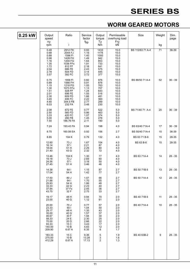
0.25 kW
0.48 2912 FK 0.93 1433 15.0 BS 112/63 71 A-4 71 36-390.68 2044 FJ 1.19 1178 15.0 0.88 1596 Fl 1.40 1000 15.0 0.98 1428 FH 1.49 942 15.0 1.16 1204 FG 1.64 853 15.0 1.35 1036 FFx 1.91 733 15.0 1.72 812 FF 2.18 641 15.0 2.04 686 FE 2.43 575 15.0 2.78 504 FD 3.14 445 15.0 3.57 392 FC 3.72 377 15.0
0.75 1856 Fl 0.82 976 10.0 BS 88/50 71 A-4 52 36 - 390.89 1566 FH 0.91 876 10.0 1.15 1218 FG 1.05 763 10.0 1.30 1073 FFx 1.13 707 10.0 1.51 928 FF 1.24 643 10.0 2.01 696 FE 1.55 516 10.0 2.30 609 FD 1.66 481 10.0 3.45 406 FC 2.22 360 10.0 4.60 304.5 FB 2.77 289 10.0 6.03 232 FA 3.48 230 10.0
2.08 672 FE 0.77 522 5.0 BS 71/40 71 A-4 20 36 - 392.50 560 FD 0.86 463 5.0 3.33 420 FC 1.07 374 5.0 5.00 280 FB 1.45 276 5.0 7.50 186.76 FA 2.11 190 5.0
7.24 193.43 FA 0.94 198 4.0 BS 63/40 71A-4 17 36 - 39
8.75 160.08 EA 0.92 156 2.7 BS 50/40 71A-4 15 36-39
8.85 104 K 0.79 132 4.0 BS 63 71 B-6 15 28-35
12.60 73 J 1.67 104 4.0 BS 63 B-6 15 28-3516.14 57 I 2.21 87 4.0 18.04 51 H 2.29 80 4.0 21.40 43 G 2.32 72 4.0
13.46 104 K 1.30 77 4.0 BS 63 71A-4 14 28 - 3519.18 73 J 2.69 60 4.0 24.56 57 I 3.18 50 4.0 27.45 51 H 3.46 46 4.0
14.38 64 I 1.15 87 2.7 BS 50 71B 6 13 28 - 3517.04 54 H 1.42 77 2.7
17.50 80 J 1.07 66 2.7 BS 50 71A-4 12 28 - 3521.88 64 I 1.70 55 2.7 25.93 54 H 1.86 48 2.7 33.33 42 G 2.23 40 2.7 37.84 37 Fx 2.45 36 2.7 43.75 32 F 2.75 33 2.7
19.17 48 H 0.94 70 2.0 BS 40 71B 6 11 28 - 3523.00 40 G 1.12 61 2.0
20.00 70 J 0.77 57 2.0 BS 40 71A-4 10 28 - 3523.33 60 I 1.04 50 2.0 29.17 48 H 1.35 43 2.0 35.00 40 G 1.57 37 2.0 46.67 30 F 1.94 30 2.0 58.33 24 E 2.30 25 2.0 70.00 20 D 2.66 22 2.0 93.33 15 C 3.43 17 2.0 140.00 10 B 4.83 12 2.0 209.90 6.67 A 6.35 8 1.7
183.33 15 C 9.36 5 1.9 BS 40 63B-2 9 28 - 35275.00 10 B 13.28 3 1.6 412.29 6.67 A 17.13 2 1.3

SERIES BS
12
WORM GEARED MOTORSOutput speed
n2 rpm
Ratio
i
Service factorfbp
Output torque
T2 Nm
Permissable overhung load
Fr2 kN
Size Weight
kg
Dim.page
0.37 kW
0.68 2044 FJ 0.80 1747 15.0 BS 112/63 71B-4 72 36-390.88 1596 Fl 0.94 1483 15.0 0.98 1428 FH 1.00 1398 15.0 1.16 1204 FG 1.10 1267 15.0 1.35 1036 FFx 1.29 1089 15.0 1.72 812 FF 1.47 954 15.0 2.04 686 FE 1.64 856 15.0 2.78 504 FD 2.11 664 15.0
2.78 504 FD 2.11 664 15.0 BS 112/63 71B-4 72 36-393.57 392 FC 2.49 563 15.0 4.55 308 FB 3.08 455 15.0
1.30 1073 FFx 0.76 1050 10.0 BS 88/50 71B-4 53 36-391.51 928 FF 0.84 954 10.0 2.01 696 FE 1.04 766 10.0 2.30 609 FD 1.12 716 10.0 3.45 406 FC 1.49 536 10.0 4.60 304.5 FB 1.86 431 10.0 6.03 232 FA 2.33 344 10.0
5.00 280 FB 0.97 411 5.0 BS 71/40 71B-4 21 36-397.50 186.76 FA 1.41 284 5.0
6.48 108 M 1.92 294 15.0 BS 112 90S-8 71 28-357.37 95 L 2.53 271 15.0
6.60 106 M 1.00 288 10.0 BS 88 90S-8 54.0 28-358.54 82 L 1.74 241 10.0 9.86 71 K 2.38 212 10.0
8.68 106 M 1.30 216 10.0 BS 88 80A-6 50 28-3511.22 82 L 2.27 180 10.0 12.96 71 K 3.15 156 10.0
8.54 82 J 0.95 228 5.0 BS 71 90S-8 24 28-35
9.20 100 K 0.78 207 5.0 BS 71 80A-6 20 28-3511.22 82 J 1.22 172 5.0 14.60 63 I 1.97 143 5.0 19.17 48 H 2.37 118 5.0
9.59 73 J 0.85 210 4.0 BS 63 90S-8 21 28-35
12.60 73 J 1.07 163 4.0 BS 63 80A-6 17 28-35
16.14 57 I 1.41 137 4.0 18.04 51 H 1.46 126 4.0
13.46 104 K 0.77 130 4.0 BS 63 71B-4 15 28-3519.18 73 J 1.60 101 4.0 24.56 57 I 1.88 85 4.0 27.45 51 H 2.05 78 4.0 32.56 43 G 2.34 68 4.0 37.84 37 Fx 2.56 57 4.0 48.28 29 F 3.18 49 4.0 12.96 54 H 0.76 159 2.7 BS 50 90S-8 19 28-35
17.04 54 H 0.90 121 2.7 BS 50 80A-6 15.0 28-35
21.88 64 I 1.04 89 2.7 BS 50 71B-4 13 28-3525.93 54 H 1.14 79 2.7 33.33 42 G 1.37 66 2.7 37.84 37 Fx 1.50 59 2.7 43.75 32 F 1.68 53 2.7 58.33 24 E 2.07 41 2.7 66.67 21 D 2.33 37 2.7
100.00 14 C 3.34 26 2.7

SERIES BS
13
WORM GEARED MOTORSOutput speed
n2 rpm
Ratio
i
Service factorfbp
Output torque
T2 Nm
Permissable overhung load
Fr2 kN
Size Weight
kg
Dim.page
0.55 kW
1.36 1036.00 FFx 0.87 1612 15.0 BS 112/63 80A-4 74 36-391.74 812.00 FF 0.99 1412 15.0 2.06 686.00 FE 1.10 1268 15.0 2.80 504.00 FD 1.42 985 15.0 3.60 392.00 FC 1.67 836 15.0 4.58 308.00 FB 2.07 677 15.0 6.50 217.00 FA 2.73 514 15.0
2.32 609.00 FD 0.75 1060 10.0 BS 88/50 80A-4 55 36-393.47 406.00 FC 1.01 795 10.0 4.63 304.50 FB 1.25 639 10.0 6.08 232.00 FA 1.57 511 10.0
7.55 186.76 FA 0.94 424 5.0 BS 71/40 80A-4 23 36-39
6.48 108.00 M 1.22 461 15.0 BS 112 90L-8 74 28-357.37 95.00 L 1.61 425 15.0 9.21 76.00 K 2.35 366 15.0
8.54 82.00 L 1.13 372 10.0 BS 88 90L-8 57 28-359.86 71.00 K 1.54 327 10.0
8.68 106.00 M 0.82 341 10.0 BS 88 80B-6 51 28-3511.22 82.00 L 1.44 285 10.0 12.96 71.00 K 2.00 246 10.0 15.86 58.00 J 2.59 216 10.0
13.30 106.00 M 1.22 221 10.0 BS 88 80A-4 50 28-3517.20 82.00 L 2.12 184 10.0 19.86 71.00K 2.74 159 10.0 24.31 58.00 J 3.51 139 10.0
11.11 63.00 I 1.07 290 5.0 BS 71 90L-8 27 28-35
11.22 82.00 J 0.78 269 5.0 BS 71 80B-6 21 28-3514.60 63.00 I 1.26 223 5.0 19.17 48.00 H 1.52 185 5.0
17.20 82.00 J 1.14 177 5.0 BS 71 80A 4 20 28-3522.38 63.00 I 1.60 146 5.0 29.38 48.00 H 1.97 119 5.0 38.11 37.00 G 2.47 96 5.0 50.36 28.00 F 2.97 76 5.0 67.14 21.00 E 3.87 59 4.6
16.14 57.00 I 0.91 212 4.0 BS 63 80B-6 18 28-3518.04 51.00 H 0.94 195 4.0 21.40 43.00 G 0.96 173 4.0
19.32 73.00 J 1.00 162 4.0 BS 63 80A-4 17 28-3524.74 57.00 I 1.18 136 4.0 27.65 51.00 H 1.28 125 4.0 32.79 43.00 G 1.46 109 4.0 38.11 37.00 Fx 1.60 92 4.0 48.62 29.00 F 1.99 78 4.0 57.55 24.50 E 2.33 69 4.0 78.33 18.00 D 2.92 51 3.9

SERIES BS
14
WORM GEARED MOTORSOutput speed
n2 rpm
Ratio
i
Service factorfbp
Output torque
T2 Nm
Permissable overhung load
Fr2 kN
Size Weight
kg
Dim.page
0.55 kW
33.57 42 G 0.87 103 2.7 BS 50 80A-4 15 28-3538.11 37 Fx 0.96 92 2.7 44.06 32 F 1.07 84 2.7 58.75 24 E 1.32 65 2.7 67.14 21 D 1.49 59 2.7 100.71 14 C 2.13 41 2.7 134.29 10.5 B 2.74 32 2.7 176.25 8 A 3.40 24 2.4 201.43 14 C 3.82 17 2.5 BS 50 71B-2 13 28-35
58.75 24 E 0.90 65 2.0 BS 40 80A-4 13 28-35
70.50 20 D 1.04 56 2.0 BS 40 80A-4 13 28-3594.00 15 C 1.34 43 2.0 141.00 10 B 1.89 30 2.0 211.39 6.67 A 2.48 20 1.7
188.00 15 C 2.40 18 1.9 BS 40 71B-2 11 28-35282.00 10 B 3.41 13 1.6 422.79 6.67 A 4.40 8 1.3
0.75 kW 2.06 686 FE 0.81 1733 15.0 BS 112/63 80B-4 75 36-392.80 504 FD 1.04 1347 15.0 3.60 392 FC 1.22 1144 15.0 4.58 308 FB 1.51 928 15.0 6.50 217 FA 1.99 705 15.0
4.63 304.5 FB 0.92 874 10.0 BS 88/50 80B-4 56 36-396.08 232 FA 1.14 699 10.0
6.48 108 M 0.87 647 15.0 BS 112 100LA 8 80 28-357.37 95 L 1.15 596 15.0 9.21 76 K 1.67 513 15.0
8.52 108 M 1.10 497 15.0 BS 112 90S-6 71 28-359.68 95 L 1.46 457 15.0 12.11 76 K 2.19 393 15.0 14.60 63 J 2.96 339 15.0
8.54 82 L 0.81 518 10.0 BS 88 100LA-8 62 28-359.86 71 K 1.11 455 10.0
11.22 82 L 1.02 400 10.0 BS 88 90S-6 54 28-3512.96 71 K 1.42 347 10.0 15.66 58 J 1.84 304 10.0
13.30 106 M 0.85 318 10.0 BS 88 80B-4 51 28-3517.20 82 L 1.48 264 10.0 19.86 71 K 1.91 229 10.0 24.31 58 J 2.44 200 10.0 30.00 47 H 3.06 166 10.0 36.15 39 G 3.76 140 10.0
14.58 48 H 0.91 339 5.0 BS 71 100LA-8 31 28-35
19.17 48 H 1.09 259 5.0 BS 71 90S-6 24 28-35
17.20 82 J 0.80 251 5.0 BS 71 80B-4 21 28-3522.38 63 I 1.13 207 5.0 29.38 48 H 1.38 169 5.0 38.11 37 G 1.74 137 5.0 50.36 28 F 2.09 108 5.0 67.14 21 E 2.72 85 4.6 88.13 16 D 3.40 66 4.0

SERIES BS
15
WORM GEARED MOTORSOutput speed
n2 rpm
Ratio
i
Service factorfbp
Output torque
T2 Nm
Permissable overhung load
Fr2 kN
Size Weight
kg
Dim.page
0.75 kW
1.1 kW
24.74 57 I 0.83 193 4.0 BS 63 80B-4 18 28-3527.65 51 H 0.90 177 4.0 32.79 43 G 1.03 155 4.0 38.11 37 Fx 1.13 130 4.0 48.62 29 F 1.40 111 4.0 57.55 24.5 E 1.64 97 4.0 78.33 18 D 2.06 72 3.9 100.71 14 C 2.64 58 3.4 128.18 11 B 3.22 46 3.0
158.33 18 D 3.59 31 3.1 BS 63 80A-2 17 28-3544.06 32 F 0.76 118 2.7 BS 50 80B-4 16 28-35
58.75 24 E 0.94 91 2.7 67.14 21 D 1.06 82 2.7 100.71 14 C 1.51 58 2.7 134.29 10.5 B 1.95 45 2.7 176.25 8 A 2.41 34 2.4
203.57 14 C 2.58 26 2.5 BS 50 80A-2 15 28-35271.43 10.5 B 3.31 20 2.2
94.00 15 C 0.95 61 2.0 BS 40 80B-4 14 28-35141.00 10 B 1.34 43 2.0 211.39 6.67 A 1.76 28 1.7
190.00 15 C 1.62 27 1.9 BS 40 80A-2 13 28-35285.00 10 B 2.30 19 1.6 427.29 6.67 A 2.97 12 1.3
3.60 392 FC 0.83 1683 15.0 BS 112/63 90S-4 78 36-394.58 308 FB 1.03 1366 15.0 6.50 217 FA 1.35 1039 15.0
7.37 95 L 0.76 895 15.0 BS 112 100LB-8 83 28-359.21 76 K 1.11 770 15.0
9.68 95 L 0.96 692 15.0 BS 112 90L-6 74 28-3512.11 76 K 1.45 594 15.0
14.60 63 J 1.96 513 15.0 BS 112 90L-6 74 28-35
13.06 108 M 1.06 495 15.0 BS 112 90S-4 71 28-3514.84 95 L 1.40 454 15.0 18.55 76 K 2.17 383 15.0 22.38 63 J 2.65 330 15.0
12.96 71 K 0.94 522 10.0 BS 88 90L-6 57 28-3515.86 58 J 1.22 458 10.0
17.20 82 L 0.97 404 10.0 BS 88 90S-4 54 28-3519.86 71 K 1.25 350 10.0 24.31 58 J 1.60 306 10.0 30.00 47 H 2.00 254 10.0 36.15 39 G 2.46 213 10.0 48.62 29 F 3.18 165 9.7 60.00 23.5 E 3.39 141 9.0
29.38 48 H 0.91 257 5.0 BS 71 90S 4 24 28-3538.11 37 G 1.14 208 5.0 50.36 28 F 1.38 163 5.0 67.14 21 E 1.79 128 4.6 88.13 16 D 2.24 100 4.0 117.50 12 C 2.84 76 3.5 151.13 9.33 B 3.62 60 3.0
48.62 29 F 0.92 169 4.0 BS 63 90S-4 21 28-3557.55 24.5 E 1.08 148 4.0 78.33 18 D 1.35 110 3.9 100.71 14 C 1.74 88 3.4 128.18 11 B 2.12 70 3.0 181.94 7.75 A 2.68 50 2.6
158.33 18 D 2.22 50 3.1 BS 63 80B-2 18 28-35203.57 14 C 2.86 40 2.7 259.09 11.00 B 3.51 32 2.4

SERIES BS
16
WORM GEARED MOTORSOutput speed
n2 rpm
Ratio
i
Service factorfbp
Output torque
T2 Nm
Permissable overhung load
Fr2 kN
Size Weight
kg
Dim.page
1.1 kW
100.71 14 C 1.00 88 2.7 BS 50 90S-4 19 28-35134.29 10.5 B 1.29 67 2.7 176.25 8 A 1.60 52 2.4
203.57 14 C 1.63 41 2.5 BS 50 80B-2 16 28-35271.43 10.5 B 2.09 31 2.2 356.25 8 A 2.59 24 1.9
285.00 10 B 1.45 30 1.6 BS 40 80B-2 14 28-35427.29 6.67 A 1.87 20 1.3
1.5 kW 4.61 308 FB 0.76 1853 15.0 BS 112/63 90L 4 81 36-396.54 217 FA 0.99 1411 15.0
9.08 76 K 0.79 1080 15.0 BS 112 112M-8 91 28-35
12.37 76 K 1.07 807 15.0 BS 112 100L-6 83 28-3514.92 63 J 1.44 697 15.0
13.15 108 M 0.76 692 15.0 BS 112 90L-4 74 28-3514.95 95 L 1.00 635 15.0 18.68 76 K 1.55 536 15.0 22.54 63 J 1.89 462 15.0 30.87 46 H 2.78 350 15.0 36.41 39 G 3.19 300 15.0
16.21 58 J 0.90 620 10.0 BS 88 100L-6 65 28-35
20.00 71 K 0.90 485 10.0 BS 88 90L-4 57 28-3524.48 58 J 1.15 424 10.0 30.21 47 H 1.44 352 10.0 36.41 39 G 1.77 296 10.0 48.97 29 F 2.30 228 9.7 60.43 23.5 E 2.44 196 9.0 72.82 19.5 D 3.01 165 8.2 90.62 15.67 C 3.56 135 7.4
50.71 28 F 1.00 225 5.0 BS 71 90L-4 27 28-3567.62 21 E 1.30 177 4.6 88.75 16 D 1.62 138 4.0 118.33 12 C 2.05 105 3.5 152.20 9.33 B 2.62 83 3.0 189.33 7.5 A 2.97 68 2.7
238.33 12 C 3.25 49 2.9 BS 71 90S-2 24 28-35
57.96 24.5 E 0.78 204 4.0 BS 63 90L-4 24 28-3578.89 18 D 0.98 152 3.9 101.43 14 C 1.26 122 3.4 129.09 11 B 1.54 97 3.0 183.23 7.75 A 1.94 69 2.6
158.89 18 D 1.55 71 3.1 BS 63 90S-2 21 28-35204.29 14 C 2.00 57 2.7 260.00 11 B 2.46 46 2.4 369.03 7.75 A 3.11 32 2.1
135.24 10.5 B 0.94 93 2.7 BS 50 90L-4 22 28-35177.50 8 A 1.16 71 2.4
204.29 14 C 1.15 57 2.5 BS 50 90S-2 19 28-35272.38 10.5 B 1.48 44 2.2 357.50 8 A 1.83 34 1.9
SERIES BS
17
WORM GEARED MOTORSOutput speed
n2 rpm
Ratio
i
Service factorfbp
Output torque
T2 Nm
Permissable overhung load
Fr2 kN
Size Weight
kg
Dim.page
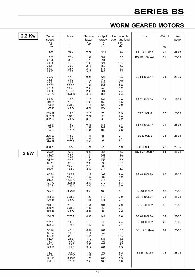
2.2 Kw
14.76 63 J 0.96 1048 15.0 BS 112 112M-6 91 28-35
18.82 76 K 1.04 802 15.0 BS 112 100LA-4 81 28-3522.70 63 J 1.26 691 15.0 31.09 46 H 1.86 524 15.0 36.67 39 G 2.13 450 15.0 51.07 28 F 2.70 331 15.0 62.17 23 E 3.23 288 13.6
30.43 47 H 0.97 523 10.0 BS 88 100LA-4 63 28-3536.67 39 G 1.19 440 10.0 49.31 29 F 1.54 339 9.7 60.85 23.5 E 1.64 291 9.0 73.33 19.5 D 2.03 245 8.2 91.26 15.67 C 2.39 201 7.4 121.70 11.75 B 3.18 154 6.3
89.38 16 D 1.10 204 4.0 BS 71 100LA-4 32 28-35119.17 12 C 1.39 155 3.5 153.27 9.33 B 1.77 123 3.0 190.67 7.5 A 2.01 100 2.7
239.17 12 C 2.13 75 2.9 BS 71 90L-2 27 28-35307.61 9.33 B 2.74 60 2.4 382.67 7.5 A 3.15 48 2.2
102.14 14 C 0.85 181 3.4 BS 63 100LA-4 29 28-35130.00 11 B 1.04 144 3.0 184.52 7.75 A 1.31 102 2.6
205.00 14 C 1.31 88 2.7 BS 63 90L-2 24 28-35260.91 11 B 1.61 70 2.4 370.32 7.75 A 2.04 50 2.1
358.75 8 A 1.21 51 1.9 BS 50 90L-2 22 28-35
3 kW 22.70 63 J 0.91 957 15.0 BS 112 100LB-4 84 28-3531.09 46 H 1.34 726 15.0 36.67 39 G 1.54 623 15.0 51.07 28 F 1.95 458 15.0 62.17 23 E 2.33 398 13.6 73.33 19.5 D 2.70 338 12.8 93.46 15.3 C 3.42 274 11.0
60.85 23.5 E 1.19 402 9.0 BS 88 100LB-4 66 28-3573.33 19.5 D 1.47 337 8.2 91.26 15.67 C 1.74 277 7.4 121.70 11.75 B 2.31 212 6.3 197.24 7.25 A 3.35 134 5.0
245.96 11.75 B 3.58 103 5.1 BS 88 100L-2 63 28-35
153.27 9.33 B 1.29 170 3.0 BS 71 100LB-4 35 28-35190.67 7.5 A 1.46 138 2.7
240.83 12 C 1.54 104 2.9 BS 71 100L-2 32 28-35309.75 9.33 B 1.97 83 2.4 385.33 7.5 A 2.27 66 2.2
184.52 7.75 A 0.95 141 2.6 BS 63 100LB-4 32 28-35
262.73 11 B 1.16 96 2.4 BS 63 100L-2 29 28-35372.90 7.75 A 1.47 69 2.1
30.98 46 H 0.99 981 15.0 BS 112 112M-4 91 28-3536.54 39 G 1.14 842 15.0 50.89 28 F 1.44 619 15.0 61.96 23 E 1.72 538 13.6 73.08 19.5 D 2.00 456 12.8 93.14 15.3 C 2.53 370 11.0 123.91 11.5 B 3.17 281 9.5
73.08 19.5 D 1.09 455 8.2 BS 88 112M-4 73 28-3590.94 15.67 C 1.29 374 7.4 121.28 11.75 B 1.71 286 6.3 196.55 7.25 A 2.49 180 5.0

SERIES BS
18
WORM GEARED MOTORSOutput speed
n2 rpm
Ratio
i
Service factorfbp
Output torque
T2 Nm
Permissable overhung load
Fr2 kN
Size Weight
kg
Dim.page
3 kW
241.70 11.75 B 2.59 142 5.1 BS 88 112M-2 72 28-35
304.39 9.33 B 1.43 114 2.4 BS 71 112M-2 41 28-35378.67 7.5 A 1.65 92 2.2
4 kW 30.98 46 H 0.99 981 15.0 BS 112 112M-4 91 28-3536.54 39 G 1.14 842 15.0 50.89 28 F 1.44 619 15.0 61.96 23 E 1.72 538 13.6 73.08 19.5 D 2.00 456 12.8 93.14 15.3 C 2.53 370 11.0 123.91 11.5 B 3.17 281 9.5
73.08 19.5 D 1.09 455 8.2 BS 88 112M-4 73 28-3590.94 15.67 C 1.29 374 7.4 121.28 11.75 B 1.71 286 6.3 196.55 7.25 A 2.49 180 5.0
241.70 11.75 B 2.59 142 5.1 BS 88 112M-2 72 28-35
304.39 9.33 B 1.43 114 2.4 BS 71 112M-2 41 28-35378.67 7.5 A 1.65 92 2.2
5.5 kW 50.89 28 F 1.04 858 15.0 BS 112 132S-4 107 28-3561.96 23 E 1.24 746 13.6 73.08 19.5 D 1.44 633 12.8 93.14 15.3 C 1.82 513 11.0
123.91 11.5 B 2.29 390 9.5 203.57 7 A 3.36 240 7.6
249.13 11.5 B 3.72 190 7.5 BS 112 132SA-2 109 28-35
121.28 11.75 B 1.24 396 6.3 BS 88 132S-4 90 28-35196.55 7.25 A 1.80 250 5.0
243.83 11.75 B 1.87 197 5.1 BS 88 132SA-2 92 28-35395.17 7.25 A 2.92 123 4.0
7.5 kW 62.17 23 E 0.91 1020 13.6 BS 112 132M-4 117 28-3573.33 19.5 D 1.05 865 12.8 93.46 15.3 C 1.33 701 11.0 124.35 11.5 B 1.67 533 9.5 204.29 7 A 2.46 328 7.6
249.57 11.5 B 2.70 263 7.5 BS 112 132SB-2 109 28-35410.00 7 A 3.75 162 6.2
197.24 7.25 A 1.32 341 5.0 BS 88 132M-4 100 28-35
244.26 11.75 B 1.36 271 5.1 BS 88 132SB-2 92 28-35
7.5 kW 73.33 19.5 D 0.88 1041 12.8 BS 112 132MD-4 129 28-3593.46 15.3 C 1.11 844 11.0 124.35 11.5 B 1.39 641 9.5 204.29 7 A 2.04 394 7.6
256.96 11.5 B 2.30 308 7.5 BS 112 132ME-2 132 28-35422.14 7 A 3.20 190 6.2
251.49 11.75 B 1.16 317 5.1 BS 88 132ME-2 115 28-35407.59 7.25 A 1.81 198 4.0

19
SERIES BS
LMB LM LB
L
øPA
HA
HB
A HD
HC
LC
LA
LC
R(4
)
LD BC
LE
øD2
øDA
HM
øDMB
øDM
LU
Worm geared motors BS40-112 Shaftmounted
Motor- Motor dimensions Gear unit dimensions size B14 B5 BS L LB L LB A BC øDA HA HB HC HD HE HH HJ LA LC øR
40 63 355 112 355 112 71 388 118 388 118 80 420 128 420 128 40 73 58 10 36 140 130 100 40 8.3 90 S 443 138 443 138 90 L 468 138 468 138
50 71 421 140 421 140 80 453 150 463 160 90 S 476 160 476 160 50 78 68 10 38 155 145 124 52 8.3 90 L 501 160 501 160
63 71 443 151 443 151 80 475 161 485 171 90 S 498 171 498 171 63 82 80 10 43 183 173 146 63 10.3 90 L 523 171 523 171 100 561.5 181.5 561.5 181.5
71 80 495 177 505 187 90 S 518 187 518 187 90L 543 187 543 187 71 101.4 92 14 49 209 195 165 68.5 12.3 100 581.5 197.5 581.5 197.5 112 595.5 197.5 595.5 197.5
88 80 (i>55) 577 213 587 223 90 S 600 223 600 223 90 L 625 223 625 223 88 275 203 115 100 664 233.5 664 233.5 112 678 233.5 678 233.5 132 (i<55) 779 266
112 90 S (i>60) 642 244 642 244 90 L (i>60) 667 244 667 244 100 (i>60) 705 254.5 705 254.5 100 718 267 718 267 112 340 252 140 112 (i>60) 720 254.5 720 254.5 112 732 267 732 267 132 821 287 160 956 317
DIMENSIONS
BS 40-71Mounting position O, hollow shaft
Position of terminal box, see page 11 Shaft tolerance, see page 57

20
SERIES BS
øTA
LMB LM LB
L
FL
G K
F
E
øPA
øFD
A
HH
HE
HJ
LU
BA
LE
BB
DL DL
T
øD2
BG
øDM øDMB
Shaft- Fan Motordimensions With dimensions brakemotor BA BB BG E F G K T øTA øD2 LE DL FD FL DM HM LM LU PA-B14 PA-B5 DMB LMB
120 125 183 92 90 140 140 140 210 102 105 160 185 73 20 92 158 152 232 113 120 200 201 72 178 161 245 122 140 200 220 75 178 161 270 122 140 200 220 75 140 150 210 102 105 160 185 73 25 98 158 162 232 113 120 200 201 72 178 172 245 122 140 200 220 75 178 172 270 122 140 200 220 75
140 163 210 102 105 160 185 73 158 175 232 113 120 200 201 72 30 101 178 184 245 122 140 200 220 75 178 184 270 122 140 200 220 75 198 204 298 136 160 250 255 106
158 183 232 113 120 200 201 72 178 192 245 122 140 200 220 75 35 122 178 192 270 122 140 200 220 75 198 212 298 136 160 250 255 106 221 231 312 155 160 250 278 109
158 200 232 113 120 200 201 72 178 209 245 122 140 200 220 75 170 140 8 200 140 70 30 20 14 45 154 45 140 55 178 209 270 122 140 200 220 75 198 229 298 136 160 250 255 106 221 248 312 155 160 250 278 109 248 255 381 165 300 317 135 178 233 245 122 140 200 220 75 178 233 270 122 140 200 220 75 198 253 298 136 160 250 255 106 210 175 18 250 175 87.5 37.5 23 18 55 174 50 140 55 198 253 298 136 160 250 255 106 221 272 312 155 160 250 278 109 221 272 312 155 160 250 278 109 248 279 381 165 300 317 135 310 332 486 210 350 375 170
BS 88-112Mounting position O, hollow shaft
Position of terminal box, see page 11 Shaft tolerance, see page 57
DIMENSIONS
21
SERIES BS
HE
øTA
K G
F
E
HG
HF
LB
L
øPA
LMLMB
øD2
L2 B LU
HM
T
BB
øDM
BA
øDMB
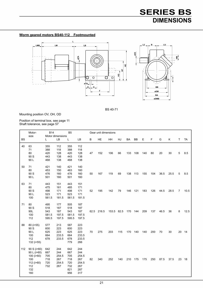
Worm geared motors BS40-112 Footmounted
Motor- B14 B5 Gear unit dimensions size Motor dimensions BS L LB L LB B HE HH HJ BA BB E F G K T TA
40 63 355 112 355 112 71 388 118 388 118 80 420 128 420 128 47 152 106 66 133 108 140 80 20 30 5 8.5 90 S 443 138 443 138 90 L 468 138 468 138
50 71 421 140 421 140 80 453 150 463 160 90 S 476 160 476 160 50 167 119 69 138 113 155 104 36.5 25.5 5 8.5 90 L 501 160 501 160
63 71 443 151 443 151 80 475 161 485 171 90 S 498 171 498 171 52 195 142 79 146 121 183 126 44.5 28.5 7 10.5 90 L 523 171 523 171 100 561.5 181.5 561.5 181.5
71 80 495 177 505 187 90 S 518 187 518 187 90L 543 187 543 187 62.5 216.5 153.5 82.5 170 144 209 137 46.5 36 8 12.5 100 581.5 197.5 581.5 197.5 112 595.5 197.5 595.5 197.5
88 80 (i>55) 577 213 587 223 90 S 600 223 600 223 90 L 625 223 625 223 70 275 203 115 170 140 140 200 70 30 20 14 100 664 233.5 664 233.5 112 678 233.5 678 233.5 132 (i<55) 779 266
112 90 S (i>60) 642 244 642 244 90 L (i>60) 667 244 667 244 100 (i>60) 705 254.5 705 254.5 100 718 267 718 267 82 340 252 140 210 175 175 250 87.5 37.5 23 18 112 (i>60) 720 254.5 720 254.5 112 732 267 732 267 132 821 287 160 956 317
BS 40-71Mounting position OV, OH, OD
Position of terminal box, see page 11 Shaft tolerance, see page 57
DIMENSIONS

22
SERIES BS
LMB LM LB
L
øPA
øFD
HJ
HH
HE
FL
øTA
G K
F
E
øD2
L2 B LU
øDM øDMB
T
BB
BA
Shaft- Fan Motor With dimensions dimensions brakemotor D2 L2 FD FL DM HM LM LU PA-B14 PA-B5 DMB LMB
120 125 183 85 90 140 140 140 210 100 105 160 185 73 20 36 158 152 232 112 120 200 201 72 178 161 245 121 140 200 220 75 178 161 270 121 140 200 220 75
140 135 210 100 105 160 185 73 25 42 158 150 232 112 120 200 201 72 178 171 245 121 140 200 220 75 178 171 270 121 140 200 220 75
140 163 210 100 105 160 185 73 158 175 232 112 120 200 201 72 30 58 178 184 245 121 140 200 220 75 178 184 270 121 140 200 220 75 198 204 298 141 160 250 255 106
158 183 232 112 120 200 201 72 178 192 245 121 140 200 220 75 35 58 178 192 270 121 140 200 220 75 198 212 298 141 160 250 255 106 221 231 312 160 160 250 278 109
158 232 112 120 200 201 72 178 245 121 140 200 220 75 45 82 140 55 178 270 121 140 200 220 75 198 298 136 160 250 255 106 221 312 156 160 250 278 109 248 381 167 300 317 135 178 245 121 140 200 220 75 178 270 121 140 200 220 75 198 298 136 160 250 255 106 55 82 140 55 198 298 136 160 250 255 106 221 312 156 160 250 278 109 221 312 156 160 250 278 109 248 381 167 300 317 135 310 486 210 350 375 170
BS 88-112Mounting position OV, OH, OD
Position of terminal box, see page 11 Shaft tolerance, see page 57
DIMENSIONS

23
SERIES BS
HE
øTA
K G
F
E
HG
HF
LB
L
øPA
LMLMB
øD2
L2 B LU
HM
T
BB
øDM
BA
øDMB
Worm geared motors BS40-112 Footmounted
Motor- Motor dimensions Gear unit dimensions size B14 B5 BS L LB L LB B HE HF HG BA BB E F G K T TA
40 63 355 112 355 112 71 388 117 388 118 80 420 128 420 128 47 152 98 58 133 108 140 80 20 30 5 8.5 90 S 443 138 443 138 90 L 468 138 468 138
50 71 421 140 421 140 80 453 150 463 160 90 S 476 160 476 160 50 167 110 60 138 113 155 104 36.5 25.5 5 8.5 90 L 501 160 501 160
63 71 443 151 443 151 80 475 161 485 171 90 S 498 171 498 171 52 195 128 65 146 121 183 126 44.5 28.5 7 10.5 90 L 523 171 523 171 100 561.5 181.5 561.5 181.5
71 80 495 177 505 187 90 S 518 187 518 187 90L 543 187 543 187 62.5 216.5 141.5 70.5 169.4 143.4 209 137 46.5 36 8 12.5 100 581.5 197.5 581.5 197.5 112 595.5 197.5 595.5 197.5
88 80 (i>55) 577 213 587 223 90 S 600 223 600 223 90 L 625 223 625 223 70 275 160 72 170 140 140 200 70 30 20 14 100 664 233.5 664 233.5 112 678 233.5 678 233.5 132 (i<55) 779 266
112 90 S (i>60) 642 244 642 244 90 L (i>60) 667 244 667 244 100 (i>60) 705 254.5 705 254.5 100 718 267 718 267 82 340 200 88 210 175 175 250 87.5 37.5 23 18 112 (i>60) 720 254.5 720 254.5 112 732 267 732 267 132 821 287 160 956 317
BS 40-71
Mounting position UV, UH, UD
Position of terminal box, see page 11 Shaft tolerance, see page 57
DIMENSIONS

24
SERIES BS
LMB LM LB
øPA
øFD
HG
HF
HE
FL
G KøTA
E
F
L
LU
T
BB
BA
øDM
øDMB
L2 B
øD2
Shaft- Fan Motor With dimensions dimensions brakemotor D2 L2 FD FL DM HM LM LU PA-B14 PA-B5 DMB LMB
120 45 183 85 90 140 140 60 210 100 105 160 185 73 20 36 158 72 232 112 120 200 201 72 178 81 245 121 140 200 220 75 178 81 270 121 140 200 220 75
140 50 210 100 105 160 185 73 25 42 158 62 232 112 120 200 201 72 178 71 245 121 140 200 220 75 178 71 270 121 140 200 220 75
140 37 210 100 105 160 185 73 158 49 232 112 120 200 201 72 30 58 178 58 245 121 140 200 220 75 178 58 270 121 140 200 220 75 198 78 298 141 160 250 255 106
158 41 232 112 120 200 201 72 178 50 245 121 140 200 220 75 35 58 178 50 270 121 140 200 220 75 198 70 298 141 160 250 255 106 221 89 312 160 160 250 278 109
158 232 112 120 200 201 72 178 245 121 140 200 220 75 45 82 140 55 178 270 121 140 200 220 75 198 298 136 160 250 255 106 221 312 156 160 250 278 109 248 381 167 300 317 135 178 245 121 140 200 220 75 178 270 121 140 200 220 75 198 298 136 160 250 255 106 55 82 140 55 198 298 136 160 250 255 106 221 312 156 160 250 278 109 221 312 156 160 250 278 109 248 381 167 300 317 135 310 486 210 350 375 170
BS 88-112
Mounting position UV, UH, UD
Position of terminal box, see page 11 Shaft tolerance, see page 57
DIMENSIONS

25
SERIES BS
LMB LM LB
L
HS
A
øMøSA
øPA
HM
øD2
øN øP
BJTE
TD
L2
LU
BH
øDM
øDMB
Worm geared motors BS40-112 Flangemounted
Motor- Motor dimensions Gear unit dimensions size B14 B5 BS L LB L LB A HS BJ M N P øSA TE TD BH
40 63 355 112 355 112 71 388 117 388 118 100 80 118 80 420 128 420 128 40 46 28 1151) 951 1401) 9 10 3 91.5 90 S 443 138 443 138 130 110 160 90 L 463 138 468 138 165 130 200
50 71 421 140 421 140 100 80 118 80 453 150 463 160 115 95 140 90 S 476 160 476 160 50 48 28 1301) 1101) 1601) 9 10 3.5 99 90 L 501 160 501 160 165 130 200
63 71 443 151 443 151 80 475 161 485 171 130 110 160 90 S 498 171 498 171 63 53 35 1651) 1301) 2001) 11 12 3.5 106 90 L 523 171 523 171 100 561.5 181.5 561.5 181.5
71 80 495 177 505 187 90 S 518 187 518 187 90L 543 187 543 187 71 63 32 165 130 200 11 12 3.5 122.4 100 581.5 197.5 581.5 197.5 112 595.5 197.5 595.5 197.5
88 80 (i>55) 577 213 587 223 90 S 600 223 600 223 90 L 625 223 625 223 88 72 24 215 180 250 14 15 4 105 100 664 233.5 664 233.5 112 678 233.5 678 233.5 132 (i<55) 779 266
112 90 S (i>60) 642 244 642 244 90 L (i>60) 667 244 667 244 100 (i>60) 705 254.5 705 254.5 100 718 267 718 267 112 88 32 265 230 300 14 15 4 125 112 (i>60) 720 254.5 720 254.5 112 732 267 732 267 132 821 287 160 956 317
BS 40-71Mounting position OH
Position of terminal box, see page 11 Shaft tolerance, see page 57
DIMENSIONS

26
SERIES BS
øFD
LMB LM LB
L
øPA
FL
øSA øM
HS
A
BJTE
TD
øD2
øN øP
L2BHBK
LU
øDM øDMB
Shaft- Fan Motor With dimensions dimensions brakemotor D2 L2 FD FL DM HM LM LU PA-B14 PA-B5 DMB LMB
120 125 183 85 90 140 140 140 210 100 105 160 185 73 20 36 158 152 232 112 120 200 201 72 178 161 245 121 140 200 220 75 178 161 270 121 140 200 220 75
140 150 210 100 105 160 185 73 25 42 158 162 232 112 120 200 201 72 178 171 245 121 140 200 220 75 178 171 270 121 140 200 220 75
140 163 210 100 105 160 185 73 158 175 232 112 120 200 201 72 30 58 178 184 245 121 140 200 220 75 178 184 270 121 140 200 220 75 198 204 298 141 160 250 255 106
158 183 232 112 120 200 201 72 178 192 245 121 140 200 220 75 35 58 178 192 270 121 140 200 220 75 198 212 298 141 160 250 255 106 221 231 312 160 160 250 278 109
158 232 112 120 200 201 72 178 245 121 140 200 220 75 45 82 140 55 178 270 121 140 200 220 75 198 298 136 160 250 255 106 221 312 156 160 250 278 109 248 381 167 300 317 135 178 245 121 140 200 220 75 178 270 121 140 200 220 75 198 298 136 160 250 255 106 55 82 140 55 198 298 136 160 250 255 106 221 312 156 160 250 278 109 221 312 156 160 250 278 109 248 381 167 300 317 135 310 486 210 300 375 170
BS 88-112Mounting position OH
Position of terminal box, see page 11 Shaft tolerance, see page 57
DIMENSIONS

27
SERIES BS
R(4
)
LC LC
LA
HDA
LU LN
LK
HB
HA
HM
HC
øDA
øD2
BCLE
LBL
LM
øDM
LD
øPA
Worm geared motors BS 50/40 - BS112/63 Shaftmounted
Motor- Motor dimensions Gear unit dimensions size B14 B5 BS L LK LB L LK LB A BC DA HA HB HC HD HE HH HJ LA LC LN R
50/40 63 355 280 112 355 280 112 71 387 295 118 388 295 118 50 78 68 10 38 155 145 124 52 124 8.3 80 420 307 128 420 307 128
63/40 63 355 302 112 355 302 112 71 387 317 118 388 317 118 63 82 80 10 43 183 173 146 63 135 8.3 80 420 329 128 420 329 128
71/40 63 355 310 112 355 310 112 71 387 325 118 388 325 118 71 101.4 92 14 49 209 195 165 68.5 139 10.3 80 420 337 128 420 337 128
88/50 71 435 412 140 435 412 140 80 467 424 150 477 424 160 88 275 203 115 180 12.3 90 S 490 433 160 490 433 160 90 L 515 433 160 515 433 160
112/63 71 466 453 151 466 453 151 80 498 465 161 508 465 171 112 340 252 140 200 90 S 521 474 171 521 474 171 90 L 546 474 171 546 474 171 100 585 494 181.5 585 494 181.5
BS 50/40 - 71/40
Mounting position O, U -P7
Position of terminal box, see page 11 Shaft tolerance, see page 57
Mounting position OV - P7
DIMENSIONS

28
SERIES BS
LK
LU LN
HM
AH
J
HH
HE
G
øTA
K
F
E
L2 B LB
L
LM
øDM
T
BB
BA
øD2
Shaft- Motor- dimensions dimensions BA BB E F G K T TA D2 L2 DM HM LM LU PA
120 95 183 85 90 138 113 155 104 36.5 25.5 4 8.5 25 42 140 110 210 100 105 158 122 232 112 120
120 108 183 85 90 146 121 183 126 44.5 28.5 5 11 30 58 140 123 210 100 105 158 135 232 112 120
120 116 183 85 90 170 144 209 137 46.5 36 6 12.5 35 58 140 131 210 100 105 158 143 232 112 120
140 138 210 100 105 170 140 200 140 70 30 20 14 45 82 158 150 232 112 120 178 159 245 121 140 178 159 270 121 140
140 149 210 100 105 158 161 232 112 120 210 175 250 175 87.5 37.5 23 18 55 82 178 170 245 121 140 178 170 270 121 140 198 190 298 141 160
BS 88/50 - 112/63
Position of terminal box, see page 11 Shaft tolerance, see page 57
DIMENSIONS

29
SERIES BS
LK
LU LN
HM
AH
J
HH
HE
øTA
G K
F
E
BB
BA
øD2
L2 B LB
L
LM
øDM
TøP
A
OV OH
Worm geared motors BS50/40 - BS 112/63 Footmounted
Motor- Motor dimensions Gear unit dimensions size B14 B5 BS L LK LB L LK LB A B HE HH HJ LN
50/40 63 387 280 112 387 280 112 71 420 295 118 420 295 118 50 50 167 119 69 124 80 452 307 128 452 307 128
63/40 63 405 302 112 405 302 112 71 438 317 118 438 317 118 63 52 195 142 79 135 80 470 329 128 470 329 128
71/40 63 415.5 310 112 415.5 310 112 71 448.5 325 118 448.5 325 118 71 62.5 216.5 153.5 82.5 139 80 480.5 337 128 480.5 337 128
88/50 71 502 412 140 502 412 140 80 536 424 150 536 424 160 88 70 275 203 115 180 90 S 557 433 160 557 433 160 90 L 582 433 160 582 433 160
112/63 71 525 453 151 525 453 151 80 557 465 161 557 465 171 112 82 340 252 140 200 90 S 580 474 171 580 474 171 90 L 605 474 171 605 474 171 100 643.5 494 181.5 643.5 494 181.5
BS 50/40 - 71/40Mounting position OV, OH, OO - P7
Position of terminal box, see page 11 Shaft tolerance, see page 57
Mounting position OV - P7
DIMENSIONS

30
SERIES BSH
M
LU LN
LK
HH
HE
HJ
øTA
G K
F
E
LB LM
L
øD
M
BB
DLDL
LE
BA
BG
øD
2
Shaft- Motor- dimensions dimensions BA BB BG E F G K T TA D2 LE DL DM HM LM LU PA
120 95 183 85 90 25 98 140 110 210 100 105 158 122 232 112 120
120 108 183 85 90 30 101 140 123 210 100 105 158 135 232 112 120
120 116 183 85 90 35 122 140 131 210 100 105 158 143 232 112 120
140 138 210 100 105 170 140 8 200 140 70 30 20 14 45 154 45 158 150 232 112 120 178 159 245 121 140 178 159 270 121 140
140 149 210 100 105 158 161 232 112 120 210 175 18 250 175 87.5 37.5 23 18 55 174 50 178 170 245 121 140 178 170 270 121 140 198 190 298 141 160
BS 88/50 - 112/63
Position of terminal box, see page 11 Shaft tolerance, see page 57
Mounting position OV - P7
DIMENSIONS

31
SERIES BS
Ratioand code
Intput speed
Output speed
Intput power
Output torque Efficiency Thermal rating 1) Overhung
load
i n1 rpm
n2 rpm
P1 kW
T2 Nm
η%
Shaft-mount
kW
Shaft-mount
kW
Fr2 N
1) Gearbox with fan or motor motor with fan, flange mounted on the gearbox.
2860 429 1.9 37 85 .89 1.2 1300 6.67 1430 214 1.3 50 86 1.1 1.3 1700 (20/3) 930 139 .99 59 87 .84 1.0 1900 A 730 109 .87 66 86 .73 .92 2000 2860 286 1.5 43 83 .86 1.1 1600 10 1430 143 1.0 57 85 1.0 1.2 2000 (20/2) 930 93 .78 69 85 .79 .99 2000 B 730 73 .68 76 85 .69 .86 2000
2860 191 1.1 44 78 .65 .87 1900 15 1430 95 .73 58 79 .75 .92 2000 (30/2) 930 62 .56 70 80 .58 .73 2000 C 730 49 .50 77 79 .51 .64 2000
2860 143 .91 44 72 .53 .70 2000 20 1430 72 .58 58 75 .60 .73 2000 (20/1) 930 46 .45 70 75 .47 .58 2000 D 730 36 .40 78 74 .41 .52 2000
2860 119 .80 44 69 .47 .62 2000 24 1430 60 .51 58 71 .53 .65 2000 (24/1) 930 39 .39 70 72 .41 .51 2000 730 30 .35 78 71 .36 .45 2000
2860 95 .69 44 64 .41 .53 2000 30 1430 48 .44 59 67 .45 .54 2000 (30/1) 930 31 .34 70 67 .35 .44 2000 F 730 24 .30 78 66 .31 .39 2000
2860 72 .57 43 56 .34 .44 2000 40 1430 36 .37 58 59 .36 .44 2000 (40/1) 930 23 .28 69 60 .28 .35 2000 G 730 18 .25 76 58 .25 .31 2000
2860 60 .52 44 52 .32 .41 2000 48 1430 30 .32 58 56 .33 .40 2000 (48/1) 930 19 .24 66 56 .26 .33 2000 H 730 15 .21 71 55 .23 .29 2000
2860 48 .45 42 46 .29 .37 2000 60 1430 24 .26 52 49 .29 .35 2000 (60/1) 930 16 .18 54 49 .23 .29 2000 I 730 12 .15 56 47 .21 .26 2000
2860 41 .39 40 43 .29 .36 2000 70 1430 20 .21 44 44 .29 .35 2000 (70/1) 930 13 .14 46 46 .23 .28 2000 J 730 10 .11 47 44 .20 .25 2000
2860 34 .32 31 34 .27 .33 2000 84 1430 17 .16 33 36 .27 .32 2000 (84/1) 930 11 .10 35 38 .21 .26 2000 K 730 8.7 .09 36 37 .19 .23 2000
BS 40 POWER RATINGS

32
SERIES BS
Ratioand code
Intput speed
Output speed
Intput power
Output torque Efficiency Thermal rating 1) Overhung
load
i n1 rpm
n2 rpm
P1 kW
T2 Nm
η%
Shaft-mount
kW
Shaft-mount
kW
Fr2 N
1) Gearbox with fan or motor motor with fan, flange mounted on the gearbox.
8 2860 358 2.6 62 88 1.7 2.2 1900 (24/3) 1430 179 1.7 83 88 1.7 2.1 2400 A 930 116 1.4 99 88 1.3 1.6 2700 730 91 1.2 110 88 1.1 1.4 2700
10.5 2860 272 2.1 65 86 1.4 1.8 2200 (21/2) 1430 136 1.4 87 87 1.4 1.7 2700 B 930 89 1.1 103 85 1.1 1.4 2700 730 70 .97 114 85 .94 1 .2 2700
14 2860 204 1.7 66 82 1.2 1.5 2500 (28/2) 1430 102 1.1 88 84 1.2 1.5 2700 C 930 66 .88 105 83 .91 1.1 2700 730 52 .77 117 83 .78 .97 2700
21 2860 136 1.2 66 76 .86 1.1 2700 (21/1) 1430 68 .80 87 77 .84 1.0 2700 D 930 44 .63 104 76 .64 .80 2700 730 35 .56 116 75 .56 .69 2700
24 2860 119 1.1 63 73 .74 .93 2700 (24/1) 1430 60 .71 85 74 .72 .87 2700 E 930 39 .57 102 72 .55 .69 2700 730 30 .49 112 72 .48 .60 2700
32 2860 89 .92 68 69 .69 .86 2700 (32/1) 1430 45 .59 90 71 .65 .79 2700 F 930 29 .47 108 69 .50 .62 2700 730 23 .41 120 69 .43 .54 2700
37 2860 77 .82 66 65 .59 .73 2700 (37/1) 1430 39 .53 88 66 .56 .67 2700 Fx 930 25 .43 106 64 .43 .53 2700 730 20 .37 116 64 .37 .47 2700 42 2860 68 .76 68 63 .57 .70 2700 (42/1) 1430 34 .49 90 65 .54 .65 2700 G 930 22 .40 109 63 .42 .51 2700 730 17 .34 120 63 .36 .45 2700
54 2860 53 .66 68 57 .49 .61 2700 (54/1) 1430 26 .42 90 59 .46 .55 2700 H 930 17 .34 109 57 .35 .43 2700 730 14 .30 120 57 .31 .38 2700
64 2860 45 .60 69 53 .46 .56 2700 (64/1) 1430 22 .39 93 55 .42 .51 2700 I 930 15 .28 100 53 .33 .40 2700 730 11 .23 102 53 .29 .36 2700
80 2860 36 .50 66 49 .44 .53 2700 (80/1) 1430 18 .27 71 49 .40 .47 2700 J 930 12 .19 75 47 .31 .38 2700
BS 50 POWER RATINGS

33
SERIES BS
Ratioand code
Intput speed
Output speed
Intput power
Output torque Efficiency Thermal rating 1) Overhung
load
i n1 rpm
n2 rpm
P1 kW
T2 Nm
η%
Shaft-mount
kW
Shaft-mount
kW
Fr2 N
1) Gearbox with fan or motor motor with fan, flange mounted on the gearbox.
BS 63 POWER RATINGS
7.75 2860 369 4.3 101 91 2.8 3.5 2100 (31/4) 1430 185 2.9 134 90 2.6 3.2 2600 A 930 120 2.3 162 90 2.0 2.4 2900 730 94 2.0 178 89 1.7 2.1 3200
11 2860 260 3.4 112 89 2.6 3.2 2400 (33/3) 1430 130 2.3 149 88 2.3 2.8 3000 B 930 85 1.8 178 88 1.7 2.1 3400 730 66 1.6 197 88 1.5 1.8 3700
14 2860 204 2.8 115 87 2.2 2.7 2700 (28/2) 1430 102 1.9 154 87 2.0 2.4 3400 C 930 66 1.3 160 86 1.5 1.8 4000 730 52 1.0 160 85 1.2 1.6 4000
18 2860 159 2.2 111 82 1.7 2.1 3100 (36/2) 1430 79 1.5 149 83 1.5 1.8 3900 D 930 52 1.2 178 83 1.1 1.4 4000 730 41 1.0 196 81 .97 1.2 4000
24.5 2860 117 1.8 119 80 1.5 1.9 3500 (49/2) 1430 58 1.2 160 81 1.4 1.6 4000 E 930 38 .81 162 79 1.0 1.3 4000 730 30 .64 162 79 .87 1.1 4000
29 2860 99 1.6 117 77 1.3 1.6 3800 (29/1) 1430 49 1.0 156 77 1.1 1.4 4000 F 930 32 .82 188 77 .86 1.1 4000 730 25 .67 192 75 .74 .92 4000
37 2860 77 1.3 109 69 .92 1.1 4000 (37/1) 1430 39 .85 147 70 .81 .97 4000 Fx 930 25 .67 175 68 .62 .77 4000 730 20 .60 194 67 .54 .67 4000
43 2860 67 1.2 121 70 1.0 1.2 4000 (43/1) 1430 33 .78 160 71 .89 1.1 4000 G 930 22 .53 166 70 .67 .82 4000 730 17 .43 165 68 .57 .71 4000
51 2860 56 1.1 121 67 .89 1.1 4000 (51/1) 1430 28 .69 160 67 .78 .93 4000 H 930 18 .53 184 66 .59 .73 4000 730 14 .42 183 65 .51 .63 4000
57 2860 50 .98 121 64 .83 1.0 4000 (57/1) 1430 25 .64 160 65 .73 .87 4000 I 930 16 .51 193 64 .55 .68 4000 730 13 .41 193 62 .47 .59 4000
73 2860 39 .85 121 58 .72 .87 4000 (73/1) 1430 20 .56 162 59 .61 .74 4000 J 930 13 .40 174 58 .47 .57 4000 730 10 .33 179 56 .41 .51 4000
104 2860 28 .56 92 47 .61 .73 4000 (104/1) 1430 14 .31 100 46 .52 .62 4000 K 930 8.9 .21 105 47 .40 .49 4000 730 7 .17 107 45 .35 .43 4000

34
SERIES BS
Ratioand code
Intput speed
Output speed
Intput power
Output torque Efficiency Thermal rating 1) Overhung
load
i n1 rpm
n2 rpm
P1 kW
T2 Nm
η%
Shaft-mount
kW
Shaft-mount
kW
Fr2 N
1) Gearbox with fan or motor motor with fan, flange mounted on the gearbox.
BS 71 POWER RATINGS
7.5 2860 381 6.5 151 92 3.2 4.4 2200 (30/4) 1430 191 4.3 201 92 3.6 3.8 2700 A 930 124 3.4 242 91 2.4 2.9 3100 730 97 3.0 267 91 2.0 2.5 3300
9.33 2860 307 5.7 163 91 3.4 4.2 2400 (28/3) 1430 153 3.8 218 91 3.1 3.7 3000 B 930 100 3.0 260 90 2.3 2.8 3400 730 78 2.6 288 89 1.9 2.4 3600
12 2860 238 4.5 160 89 2.7 3.3 2900 (36/3) 1430 119 3.0 215 88 2.4 2.9 3500 C 930 78 2.3 255 88 1.8 2.2 4000 730 61 2.0 282 87 1.5 1.9 4300
16 2860 179 3.6 169 87 2.3 2.8 3300 (32/2) 1430 89 2.4 224 87 2.0 2.5 4000 D 930 58 1.9 269 85 1.5 1.9 4600 730 46 1.7 297 85 1.3 1.6 5000
21 2860 136 2.9 173 84 2.0 2.4 3700 (42/2) 1430 68 1.9 230 84 1.7 2.0 4600 E 930 44 1.5 276 83 1.3 1.6 5000 730 35 1.4 305 82 1.1 1.4 5000
28 2860 102 2.2 168 80 1.5 1 .8 4200 (28/1) 1430 51 1.5 225 79 1.3 1.5 5000 F 930 33 1.2 267 77 .97 1.2 5000 730 26 1.0 298 77 .83 1.0 5000
37 2860 77 1.9 178 76 1.3 1.6 4700 (37/1) 1430 39 1.3 238 76 1.1 1.3 5000 G 930 25 1.0 283 74 .84 1.0 5000 730 20 .89 315 73 .72 .89 5000
48 2860 60 1.5 175 71 1.1 1.3 5000 (48/1) 1430 30 1.0 234 71 .93 1.1 5000 H 930 19 .82 281 69 .70 .86 5000 730 15 .72 310 68 .60 .75 5000
63 2860 45 1.3 175 66 .89 1.1 5000 (63/1) 1430 23 .85 234 65 .76 .91 5000 I 930 15 .69 281 63 .58 .71 5000 730 12 .61 310 61 .51 .63 5000
82 2860 35 1.1 178 60 .77 .92 5000 (82/1) 1430 17 .62 201 58 .66 .79 5000 J 930 11 .45 211 56 .50 .61 5000 730 8.9 .37 216 54 .44 .54 5000
100 2860 29 .77 143 56 .76 .91 5000 (100/1) 1430 14 .42 154 54 .64 .77 5000 K 930 9.3 .30 162 49 .49 .60 5000 730 7.3 .25 166 43 .43 .53 5000
35
SERIES BS
Ratioand code
Intput speed
Output speed
Intput power
Output torque Efficiency Thermal rating 1) Overhung
load
i n1 rpm
n2 rpm
P1 kW
T2 Nm
η%
Shaft-mount
kW
Shaft-mount
kW
Fr2 N
1) Gearbox with fan or motor motor with fan, flange mounted on the gearbox.
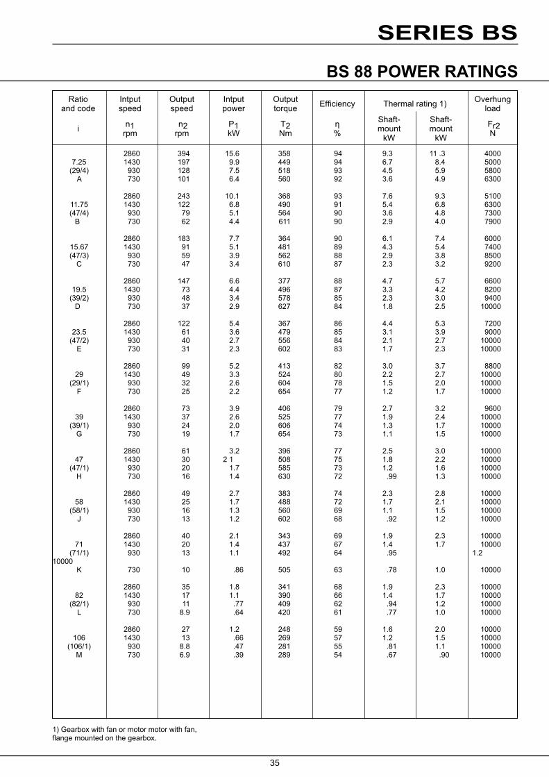
BS 88 POWER RATINGS
2860 394 15.6 358 94 9.3 11 .3 4000 7.25 1430 197 9.9 449 94 6.7 8.4 5000 (29/4) 930 128 7.5 518 93 4.5 5.9 5800 A 730 101 6.4 560 92 3.6 4.9 6300
2860 243 10.1 368 93 7.6 9.3 5100 11.75 1430 122 6.8 490 91 5.4 6.8 6300 (47/4) 930 79 5.1 564 90 3.6 4.8 7300 B 730 62 4.4 611 90 2.9 4.0 7900
2860 183 7.7 364 90 6.1 7.4 6000 15.67 1430 91 5.1 481 89 4.3 5.4 7400 (47/3) 930 59 3.9 562 88 2.9 3.8 8500 C 730 47 3.4 610 87 2.3 3.2 9200
2860 147 6.6 377 88 4.7 5.7 6600 19.5 1430 73 4.4 496 87 3.3 4.2 8200 (39/2) 930 48 3.4 578 85 2.3 3.0 9400 D 730 37 2.9 627 84 1.8 2.5 10000
2860 122 5.4 367 86 4.4 5.3 7200 23.5 1430 61 3.6 479 85 3.1 3.9 9000 (47/2) 930 40 2.7 556 84 2.1 2.7 10000 E 730 31 2.3 602 83 1.7 2.3 10000
2860 99 5.2 413 82 3.0 3.7 8800 29 1430 49 3.3 524 80 2.2 2.7 10000 (29/1) 930 32 2.6 604 78 1.5 2.0 10000 F 730 25 2.2 654 77 1.2 1.7 10000
2860 73 3.9 406 79 2.7 3.2 9600 39 1430 37 2.6 525 77 1.9 2.4 10000 (39/1) 930 24 2.0 606 74 1.3 1.7 10000 G 730 19 1.7 654 73 1.1 1.5 10000
2860 61 3.2 396 77 2.5 3.0 10000 47 1430 30 2 1 508 75 1.8 2.2 10000 (47/1) 930 20 1.7 585 73 1.2 1.6 10000 H 730 16 1.4 630 72 .99 1.3 10000
2860 49 2.7 383 74 2.3 2.8 10000 58 1430 25 1.7 488 72 1.7 2.1 10000 (58/1) 930 16 1.3 560 69 1.1 1.5 10000 J 730 13 1.2 602 68 .92 1.2 10000
2860 40 2.1 343 69 1.9 2.3 10000 71 1430 20 1.4 437 67 1.4 1.7 10000 (71/1) 930 13 1.1 492 64 .95 1.2 10000 K 730 10 .86 505 63 .78 1.0 10000
2860 35 1.8 341 68 1.9 2.3 10000 82 1430 17 1.1 390 66 1.4 1.7 10000 (82/1) 930 11 .77 409 62 .94 1.2 10000 L 730 8.9 .64 420 61 .77 1.0 10000
2860 27 1.2 248 59 1.6 2.0 10000 106 1430 13 .66 269 57 1.2 1.5 10000 (106/1) 930 8.8 .47 281 55 .81 1.1 10000 M 730 6.9 .39 289 54 .67 .90 10000

36
SERIES BS
Ratioand code
Intput speed
Output speed
Intput power
Output torque Efficiency Thermal rating 1) Overhung
load
i n1 rpm
n2 rpm
P1 kW
T2 Nm
η%
Shaft-mount
kW
Shaft-mount
kW
Fr2 N
1) Gearbox with fan or motor motor with fan, flange mounted on the gearbox.
BS 112 POWER RATINGS
7 2860 409 27.3 607 95 20.0 24.1 6200 (28/4) 1430 204 18.3 806 94 13.9 17.2 7600 A 930 133 13.8 929 93 9.3 12.2 8900 730 104 11.7 1006 93 7.4 10.0 9500
11.5 2860 249 19.7 709 93 17.5 21.0 7500 (46/4) 1430 124 12.5 891 93 11.8 14.6 9500 B 930 81 9.4 1026 92 7.8 10.2 10900 730 63 8.1 1111 91 6.2 8.4 11800
15.3 2860 187 14.9 705 92 14.0 16.8 8900 (46/3) 1430 93 10.0 936 91 9.4 11.6 11000 C 930 61 7.6 1078 90 6.3 8.2 12700 730 48 6.5 1167 90 5.0 6.7 13800
19.5 2860 147 11.8 691 89 10.6 12.7 10300 (39/2) 1430 73 7.9 912 88 7.2 9.0 12800 D 930 48 6.0 1064 87 4.8 6.3 14800 730 37 5.2 1155 87 3.8 5.2 15000
23 2860 124 10.3 708 89 10.0 11.9 10900 (46/2) 1430 62 6.8 928 88 6.7 8.3 13600 E 930 40 5.3 1080 86 4.5 5.9 15000 730 32 4.5 1171 85 3.6 4.8 15000
28 2860 102 8.6 679 84 6.5 7.7 12100 (28/1) 1430 51 5.7 893 83 4.5 5.5 15000 F 930 33 4.5 1041 80 3.1 4.0 15000 730 26 3.9 1129 79 2.5 3.3 15000
39 2860 73 6.9 741 82 5.9 7.1 13700 (39/1 ) 1430 37 4.6 960 80 4.1 5.0 15000 G 930 24 3.5 1111 78 2.8 3.6 15000 730 19 3.0 1200 77 2.2 3.0 15000
46 2860 62 6.1 755 81 5.6 6.7 14600 (46/1) 1430 31 4.0 974 79 3.8 4.7 15000 H 930 20 2.1 1124 77 2.6 3.4 15000 730 16 1.8 1212 75 2.1 2.8 15000 63 2860 45 4.2 684 77 4.8 5.8 15000 (63/1) 1430 23 2.7 874 75 3.3 4.1 15000 J 930 15 3.1 1003 73 2.2 2.9 15000 730 12 2.7 1065 71 1.8 2.4 15000
76 2860 38 3.5 654 73 4.4 5.2 15000 (76/1) 1430 19 2.3 831 71 3.0 3.7 15000 K 930 12 1.6 861 69 2.0 2.6 15000 730 9.6 1.3 858 68 1.6 2.2 15000 95 2860 30 2.7 587 69 3.7 4.4 15000 (95/1) 1430 15 1.5 636 66 2.5 3.1 15000 L 930 9.8 1.1 667 63 1.7 2.2 15000 730 7.7 .89 684 62 1.4 1.9 15000
108 2860 26 2.1 484 64 3.4 4.0 15000 (108/1) 1430 13 1.2 524 61 2.3 2.9 15000 M 930 8.6 .83 549 59 1.6 1.7 15000 730 6.8 .69 563 58 1.3 1.7 15000

37
SERIES BS
Ratioand code
Intput speed
Output speed
Intput power
Output torque Efficiency Thermal rating 1) Overhung
load
Code i n1 rpm
n2 rpm
P1 kW
T2 Nm
η%
Shaft-mountkW
Shaft-mountkW
Fr2 N
1) Gearbox with fan or motor motor with fan, flangemountedonthegearbox.
DOUBLE WORM GEARSPOWER RATINGS
BS 50/40 EA 160 1430 8.9 .31 150 45 .30 .38 2700 EB 240 1430 6 .24 150 39 .27 .34 2700 EC 360 1430 4 .20 150 32 .25 .31 2700 ED 480 1430 3 .17 150 28 .23 .30 2700 EE 576 1430 2.5 .16 150 25 .23 .29 2700 EF 720 1430 2 .14 150 22 .22 .28 2700 EG 960 1430 1.5 .13 150 18 .21 .27 2700 EH 1152 1430 1.2 .12 150 16 .21 .27 2700 El 1440 1430 1 .12 150 13 .20 .26 2700 EJ 1680 1430 0.9 .12 150 12 .20 .26 2700 EK 2016 1430 0.7 .11 150 10 .20 .26 2700
BS 63/40 FA 193 1430 7.4 .40 250 48 .44 .56 4000 FB 290 1430 4.9 .31 250 42 .40 .51 4000 FC 435 1430 3.3 .25 250 34 .36 .46 4000 FD 580 1430 2.5 .23 250 29 .35 .44 4000 FE 696 1430 2.1 .21 250 26 .33 .42 4000 FF 870 1430 1.6 .18 250 23 .32 .41 4000 FG 1160 1430 1.2 .17 250 19 .31 .39 4000 FH 1392 1430 1 .16 250 16 .30 .39 4000 Fl 1740 1430 0.8 .15 250 14 .29 .35 4000 FJ 2030 1430 0.7 .15 250 12 .29 .35 4000 FK 2436 1430 0.6 .14 250 11 .27 .32 4000
BS 71/40 FA 187 1430 7.7 .58 400 55 .50 .63 5000 FB 280 1430 5.1 .43 400 50 .44 .56 5000 FC 420 1430 3.4 .33 400 42 .40 .51 5000 FD 560 1430 2.6 .28 400 38 .38 .48 5000 FE 672 1430 2.1 .26 400 34 .37 .47 5000 FF 840 1430 1.7 .23 400 31 .35 .45 5000 FG 1120 1430 1.3 .20 400 26 .34 .43 5000 FH 1344 1430 1.1 .18 400 24 .33 .40 5000 Fl 1680 1430 0.9 .17 400 21 .29 .35 5000 FJ 1960 1430 0.7 .16 400 19 .29 .35 5000 FK 2352 1430 0.6 .15 400 17 .27 .32 5000 BS 88/50 FA 232 1430 6.2 .92 800 56 .61 .89 10000 FB 304 1430 4.7 .75 800 52 .57 .82 10000 FC 406 1430 3.5 .62 800 47 .53 .77 10000 FD 609 1430 2.3 .47 800 41 .48 .69 10000 FE 696 1430 2.1 .45 800 38 .47 .68 10000 FF 928 1430 1.5 .37 800 34 .44 .64 10000 FFX 1073 1430 1.3 .35 800 32 .43 .63 10000 FG 1218 1430 1.2 .32 800 30 .43 .62 10000 FH 1566 1430 0.9 .29 800 26 .42 .55 10000 Fl 1856 1430 0.8 .27 800 24 .41 .51 10000 FJ 2320 1430 0.6 .23 800 22 .40 .47 10000
BS 112/63 FA 217 1430 6.6 1.6 1400 61 1.2 1.7 15000 FB 308 1430 4.6 1.2 1400 56 1.1 1.6 15000 FC 392 1430 3.6 1.0 1400 53 1.0 1.5 15000 FD 504 1430 2.8 .86 1400 48 .95 1.4 15000 FE 686 1430 2.1 .68 1400 44 .89 1.3 15000 FF 812 1430 1.8 .62 1400 41 .85 1.2 15000 FFX 1036 1430 1.4 .56 1400 36 .81 .97 15000 FG 1204 1430 1.2 .49 1400 35 .79 1.1 15000 FH 1428 1430 1.0 .45 1400 32 .77 .93 15000 Fl 1596 1430 0.9 .42 1400 30 .73 .87 15000 FJ 2044 1430 0.7 .37 1400 27 .61 .74 15000 FK 2912 1430 0.5 .31 1400 22 .52 .62 15000
38
SERIES BS
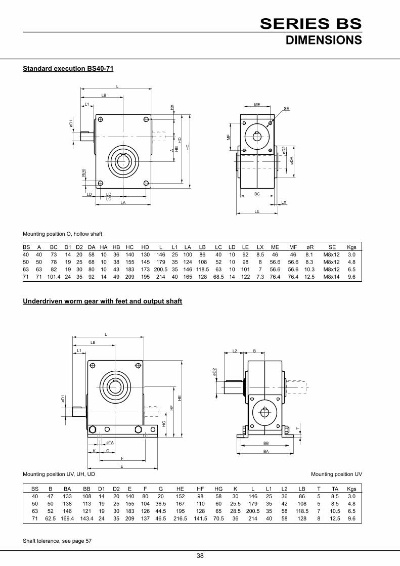
Standard execution BS40-71
BS A BC D1 D2 DA HA HB HC HD L L1 LA LB LC LD LE LX ME MF øR SE Kgs 40 40 73 14 20 58 10 36 140 130 146 25 100 86 40 10 92 8.5 46 46 8.1 M8x12 3.0 50 50 78 19 25 68 10 38 155 145 179 35 124 108 52 10 98 8 56.6 56.6 8.3 M8x12 4.8 63 63 82 19 30 80 10 43 183 173 200.5 35 146 118.5 63 10 101 7 56.6 56.6 10.3 M8x12 6.5 71 71 101.4 24 35 92 14 49 209 195 214 40 165 128 68.5 14 122 7.3 76.4 76.4 12.5 M8x14 9.6
Underdriven worm gear with feet and output shaft
DIMENSIONS
Mounting position O, hollow shaft
Mounting position UV, UH, UD Mounting position UV
Shaft tolerance, see page 57
BS B BA BB D1 D2 E F G HE HF HG K L L1 L2 LB T TA Kgs 40 47 133 108 14 20 140 80 20 152 98 58 30 146 25 36 86 5 8.5 3.0 50 50 138 113 19 25 155 104 36.5 167 110 60 25.5 179 35 42 108 5 8.5 4.8 63 52 146 121 19 30 183 126 44.5 195 128 65 28.5 200.5 35 58 118.5 7 10.5 6.5 71 62.5 169.4 143.4 24 35 209 137 46.5 216.5 141.5 70.5 36 214 40 58 128 8 12.5 9.6
BC
LE
øDA
øD2
SE
MF
A HB
HD
HC
HA
L
LB
L1
øD1
R(4
)
LCLC
LD
LX
ME
LA
øD1
L1
LB
L
F
E
G
øTA BB
BA
T
øD2
L2 B
HG
HF
HE
K

39
SERIES BS
E
F
øTA
GA K
HE
LB
L1
øD1 B
BB
BA
HK
F
E
G K
øTA BB
BA
T
øD2
HH
HE
L1
LB
L
L2 B
HG
øD
1
Overdriven worm gear with feet and output shaft
BS B BA BB D1 D2 E F G HE HH HG K L L1 L2 LB T TA Kgs 40 47 133 108 14 20 140 80 20 152 106 66 30 146 25 36 86 5 8.5 3.0 50 50 138 113 19 25 155 104 36.5 167 119 69 25.5 179 35 42 108 5 8.5 4.8 63 52 146 121 19 30 183 126 44.5 195 142 79 28.5 200.5 35 58 118.5 7 10.5 6.5 71 62.5 169.4 143.4 24 35 209 137 46.5 216.5 153.5 82.5 36 214 40 58 128 8 12.5 9.6
Worm gear with vertical worm screw, feet and output shaft
Mounting position VV, VH, VD Mounting position VV
Shaft tolerance, see page 57
BS B BA BB D1 D2 E F GA HE HK K L1 L2 LB T TA Kgs 40 47 133 108 14 20 140 80 24 62 148 30 25 36 86 5 8.5 3.9 50 50 138 113 19 25 155 104 31.5 74 182 25.5 35 42 108 5 8.5 6.1 63 52 146 121 19 30 183 126 38.5 85 203.5 28.5 35 58 118.5 7 10.5 8.3 71 62.5 169.4 143.4 24 35 209 137 39 90 218 36 40 58 128 8 12.5 12.0
Mounting position OV, OH, OD Mounting position OV
DIMENSIONS

40
SERIES BS
øMA
øNA
øS
øD
2
DA
BC
LE
HA
HB
A
HD
HC
LCLC
LA
LD
R(4
)
øP
A
TM
LB
L
BS40 M90 45
BS71 45
TC
BD
KA GB
BF
BE
B HI
L2H
N
A
L
LB
øD2L1
øD1
LF
LE
øTB
Worm gear with horizontal input shaft and feet
BS A B BD BE BF D1 D2 GB HI HN KA L L1 L2 LB LE LF TB TC X Kgs 40 40 47 40 181 162 14 20 57 131.5 48.5 9.5 146 25 36 86 100 80 9 12 49 4.1 50 50 50 40 196 177 19 25 59 143 51 9.5 179 35 42 108 124 104 9 12 52 6.4 63 63 52 45 233 213 19 30 68 163 53 10 200.5 35 58 118.5 146 126 11 12 54 8.7 71 71 62.5 55 266 241 24 35 79 186.5 66 12.5 214 40 58 128 165 137 12.5 15 64.5 12.7
Standard execution with motorflange
MountingpositionHU,HN,HD.Alsostatepositionofinputshaft Aor B. MountingpositionHU-B
Mounting position O- or U-hollow shaft
Shaft tolerance, see page 57
Size Motor- Flange size type A BC D2 DA HA HB HC HD L LA LB LC LD LE MA NA PA øR S TM Kgs 63 B14 172 112 75 60 92 6 8 3.6 40 71 B14 40 73 20 58 10 36 140 130 178 100 118 40 10 92 85 70 102 8.3 7 9 3.6 80 B14 188 128 100 80 118 7 10 3.6 90 B14 198 138 115 95 140 9 12 3.6 71 B14 211 140 85 70 108 7 10 5.5 50 80 B14 50 78 25 68 10 38 155 145 221 124 150 52 10 98 100 80 118 8.3 7 10 5.7 90 B14 231 160 115 95 140 9 12 5.9 71 B14 233 151 85 70 108 7 10 7.2 63 80 B14 63 82 30 80 10 43 183 173 243 146 161 63 10 101 100 80 118 10.3 7 10 7.4 90 B14 253 171 115 95 140 9 12 7.6 100 B14 263.5 181.5 130 110 160 9 12 7.8 80 B14 263 177 100 80 118 7 10 10.6 71 90 B14 71 104.5 35 92 14 49 209 195 273 165 187 68.5 14 122 115 95 140 12.3 9 12 10.8 100/112 B14 283.5 197.5 130 110 160 9 12 11.0
DIMENSIONS

41
SERIES BS
øP
A
TM
LB
L
F
E
G K
øTA
HJ
HH
HE
øD
2
L2 B
BB
BA
øS
øN
A
øM
A
T
BS71 45°
BS40 M90 45°
øPA
TM
LB
L
HG
HF
HE
øTA
K G
F
E
T
BB
BA
øS
øNA
øMA
øD2
L2 B
BS71 45°BS40 M90 45°
Underdriven worm gear with feet, output shaft and motorflange
Overdriven worm gear with feet, output shaft and motorflange
Mounting position OV
Shaft tolerance, see page 57
Mounting position UV, UH, UD Mounting position UV
Size Motor- Flange size type B BA BB D2 E F G HE HH HJ K L L2 LB MA NA PA S T TA TM 63 B14 172 112 75 60 92 6 8 40 71 B14 47 133 108 20 140 80 20 152 106 66 30 178 36 118 85 70 102 7 5 8.5 9 80 B14 188 128 100 80 118 7 10 90 B14 198 138 115 95 140 9 10 71 B14 211 140 85 70 108 7 10 50 B14 50 138 113 25 155 104 36.5 167 110 60 25.5 221 42 150 100 80 118 7 5 8.5 10 90 B14 231 160 115 95 140 9 12 71 B14 233 151 85 70 108 7 10 63 80 B14 52 146 121 30 183 126 44.5 195 142 79 28.5 243 58 161 100 80 118 7 5 10.5 12 90 B14 253 171 115 95 140 9 12 100 B14 263.5 181.5 130 110 160 9 12 80 B14 263 177 100 80 118 7 10 71 90 B14 62.5 169.4 143.4 35 209 137 46.5 216.5 153.5 82.5 36 273 58 187 115 95 140 9 8 12.5 12
Size Motor- Flange size type B BA BB D2 E F G HE HF HG K L L2 LB MA NA PA TA TM S T 63 B14 172 112 75 60 92 8 6 40 B14 47 133 108 20 140 80 20 152 98 58 30 178 36 118 85 70 102 8.5 9 7 5 80 B14 188 128 100 80 118 10 7 90 B14 198 138 115 95 140 10 9 71 B14 211 140 85 70 108 10 7 50 B14 50 138 113 25 155 104 36.5 167 110 60 25.5 221 42 150 100 80 118 8.5 10 7 5 90 B14 231 160 115 95 140 12 9 71 B14 233 151 85 70 108 10 7 63 80 B14 52 146 121 30 183 126 44.5 195 128 65 28.5 243 58 161 100 80 118 10.5 10 7 7 90 B14 253 171 115 95 140 12 9 100 B14 263.5 181.5 130 110 160 12 9 80 B14 263 177 100 80 118 10 7 71 90 B14 62.5 169.4 143.4 35 209 137 46.5 217 142 71 36 273 58 187 115 95 140 12.5 12 9 8 100/112 B14 283.5 197.5 130 110 160 12 9
DIMENSIONS

42
SERIES BS
BS 40 M71-M80 0°
øNA
øMA
BENZLERS
LB
øPA
TM
øS BS 50-63 0°
B
øMA
øNA
øS(4x)
L2
BB
BA
T
øTA
GA K
F
E
øPA
TM
HL
HR
LB
øD2
BS71 45°
Worm gear with vertical worm screw, feet, output shaft and motorflange
Motorflange type B5
Mounting position VV, VH, VD Mounting position VV
Size Motor- Flange size type B BA BB D2EFGAHRHL K L2 LB MA NA PA S T TA TM Vikt 40 63 B14 174 112 75 60 92 6 8 4.5 71 B14 47 133 108 20 140 80 24 180 62 30 36 118 85 70 102 7 5 8.5 9 4.5 80 B14 190 128 100 80 118 7 10 4.5 90 B14 200 138 115 95 140 9 10 4.5 71 B14 214 140 85 70 108 7 10 6.8 50 80 B14 50 138 113 25 155 104 31.5 224 74 25.5 42 150 100 80 118 7 5 8.5 10 7.0 90 B14 234 160 115 95 140 9 12 7.2 71 B14 236 151 85 70 108 10 9.0 63 80 B14 52 146 121 30 183 126 38.5 246 85 28.5 58 161 100 80 118 7 10.5 10 9.2 90 B14 256 171 115 95 140 9 7 12 9.4 100 B14 266.5 181.5 130 110 160 9 12 9.6 71 80 B14 267 177 100 80 118 7 10 13.0 90 B14 62.5 169.4 143.4 35 209 137 39 277 90 36 58 187 115 95 140 9 8 12.5 12 13.2 100/112 B14 287.5 197.5 130 110 160 9 12 13.4
BS 40 M71-M80 0°
øNA
øMA
BENZLERS
LB
øPA
TM
øS BS 50-63 0°
Size Motorsize LB MA NA PA S TM 63 112 115 95 140 9 9 BS 40 71 118 130 110 160 9 9 80 128 165 130 200 11.5 10 90 138 165 130 200 11.5 10
71 140 130 110 160 9 10 BS 50 80 160 165 130 200 11.5 12 90 160 165 130 200 11.5 12
71 151 130 110 160 9 10 BS 63 80 171 165 130 200 11.5 12 90 171 165 130 200 11.5 12 100 181.5 215 180 250 14 12
80 187 165 130 200 11.5 12 BS 71 90 187 165 130 200 11.5 12 100/112 197.5 215 180 250 14 12
DIMENSIONS

43
SERIES BS
L
LB
FL
ØFD
HJ
HH
HE
øTA
G K
E
F
L1
øD1
L2 B
øD2
BB
BA
T
ME
MF
SE
L
LB
FL
ØFD
HJ
HH
HE
øTA
G K
E
F
L1
øD1
ME SE
MF
BB
LE
BA
DL DL
BG
øD2
T
L
LB
FL
ØFD
HJ
HH
HE
øTA
G K
E
F
L1
øD1
L2 B
øD2
BB
BA
T
ME
MF
SE
L
LB
FL
ØFD
HJ
HH
HE
øTA
G K
E
F
L1
øD1
ME SE
MF
BB
LE
BA
DL DL
BG
øD2
T
BS 88-112 Worm gear with feet and output shaft
BS 88-112 Worm gear with hollow shaft
Mounting position O-hollow shaft Mounting position O-hollow shaft
Shaft tolerance, see page 57
Size Ratio BB BA BG D2 D1 DL E F G HH HJ HE K L L1 LB LE T TA SE ME MF Kgs
BS <55 140 170 8 45 28 45 140 200 70 203 115 275 30 300 42 168 154 20 14 M10x18 95 120 39 88 >55 140 170 8 45 24 45 140 200 70 203 115 275 30 300 42 168 154 20 14 M10x18 95 120 39
BS <60 175 210 18 55 35 50 175 250 87.5 252 140 340 37.5 355 58 202 174 23 18 M10x20 95 120 56 112 >60 175 210 18 55 28 50 175 250 87.5 252 140 340 37.5 339 42 186 174 23 18 M10x20 95 120 56
Size FD FL
BS 88 140 55
BS 112 140 55Mounting position OV, OH, OD Mounting position OV
Size Ratio BB BA B E K F G D2 D1 L2 L1 HH T HJ HE L LB TA SE ME MF Kgs
BS <55 140 170 70 140 30 200 70 45 28 82 42 203 20 115 275 300 168 14 M10x18 95 120 40 88 >55 140 170 70 140 30 200 70 45 24 82 42 203 20 115 275 300 168 14 M10x18 95 120 40
BS <60 175 210 82 175 37.5 250 87.5 55 35 82 58 252 23 140 340 355 202 18 M10x20 95 120 57 112 >60 175 210 82 175 37.5 250 87.5 55 28 82 42 252 23 140 340 339 186 18 M10x20 95 120 57
DIMENSIONS

44
SERIES BS
LF
LE
øD1
A
BL2
HN
BF
BE
GB
BD
øTB
KA
HM
øFD
FL
L
LB
øD2L1
TC
øS
øPA
øNA
øMA
HH
TM
LB
L
LF
LE
øD1
A
BL2
HN
BF
BE
GB
BD
øTB
KA
HM
øFD
FL
L
LB
øD2L1
TC
øS
øPA
øNA
øMA
HH
TM
LB
L
Worm gear BS88-112 with horizontal input shaft and feet
Size Ratio A B BD BF BE D1 D2 L2 L1 FD FL GB HM HN L LB LF LE KA TB TC Kgs Oil(lit) BS <55 88 70 45 335 365 28 45 82 42 140 55 102 252 100 300 168 120 200 15 14 7 40 1.5 88 >55 88 70 45 335 365 24 45 82 42 140 55 102 252 100 300 168 120 200 15 14 7 40 1.5
BS <60 112 82 60 420 460 35 55 82 58 140 55 128 289 125 355 202 135 250 20 18 10 57 1.6 112 >60 112 82 60 420 460 28 55 82 42 140 55 128 289 125 339 186 135 250 20 18 10 57 1.6
BS 88-112 Motorflange
MountingpositionHU,HN,HD.Alsostatepositionofinputshaft Aor B. MountingpositionHU-A
Shaft tolerance, see page 57
Size Motor B14 Flange B5 Flange size HH L LB MA NA PA S TM L LB MA NA PA S TM Vikt i>55 80 203 345 213 100 80H7 118 7 10 355 223 165 130H7 200 11.5 12 41 BS 90 203 355 233 115 95H7 140 9 12 355 223 165 130H7 200 11.5 12 41 88 100/112 203 365 233.5 130 110H7 160 9 12 365 233.5 215 180H7 250 14 12 42 i<55 132 203 398 266 265 230H7 300 14 13 50
i>60 90 252 397 244 115 95H7 140 9 12 397 244 165 130H7 200 11.5 12 58 BS i>60 252 408 254.5 130 110H7 160 9 12 408 254.5 215 180H7 250 14 12 59 112 100/112 252 420 267 130 110H7 160 9 12 420 267 215 180H7 250 14 12 61 132 252 440 287 265 230H7 300 14 13 67
Mounting position OH, OV, OD Mounting position OV
DIMENSIONS

45
SERIES BS
øMøSA
BJ TE TD
øD2
øN øP
L2BH
ØM
ØSA
BH L2TDTE
BJ
ØD
2Ø
NØ
P
Execution with output flange and shaft BS40-112
Shaft tolerance, see page 57
1) Standard execution, othersonrequest
Size BH D2 L2 BJ M N P SA TE TD Vikt
BS 40 91.5 20 36 28 100 80h7 118 7 10 3 4.1 1151 95h71 1401 9 130 110h7 160 9 165 130h7 200 11 BS 50 99 25 42 28 100 80h7 118 7 10 3.5 6.6 115 95h7 140 9 1301 110h71 1601 9 165 130h7 200 11 BS 63 106 30 58 35 130 110h7 160 9 12 3.5 9.3 1651 130h71 2001 11 BS 71 122.4 35 58 32 165 130h7 200 11 12 3.5 13.9 BS 88 105 45 82 24 215 180j6 250 14 15 4 47 BS 112 125 55 82 32 265 230j6 300 14 15 4 69
øMøSA
BJ TE TD
øD2
øN øP
L2BH
ØM
ØSA
BH L2TDTE
BJ
ØD
2Ø
NØ
P
DIMENSIONS

46
SERIES BS
BL TF
BO
20°
20°
øSB
LSLN
HT
AK AS
AT
LS
20°
HT
ØS
BL TF
BO
20°
20°
øSB
LSLN
HT
AK AS
AT
LS
20°
HT
ØS
Execution with torque arm
LS Size AK AS AT BO HT BL LN min/max S SB TF Kgs
BS 40 - - - 9 76 36.5 70 165/245 - 8 4 4.0 BS 50 - - - 9 88 39 85 165/245 . 8 5 5.8 BS63 - - - 11 106 41 103 190/290 - 3/8” 5 7.5 BS71 - - - 11 120 50.7 107.5 190/290 - 3/8” 5 10.7 BS 88 47 18 - - 190 - 460/600 16 - - 40.0 BS 112 60 18 5 - 240 - 480/600 16 - - 57
Torquearmshallbemountedfortension (see arrows).
DIMENSIONS
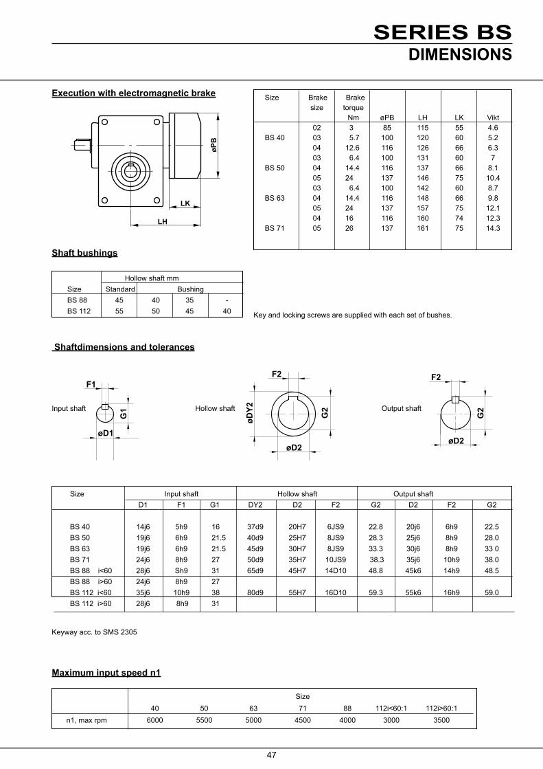
47
SERIES BS
øD1
G1
F1F2
øDY2
øD2
G2
F2
G2
øD2
Execution with electromagnetic brake
Keyway acc. to SMS 2305
Input shaft Hollow shaft Output shaft
Size Input shaft Hollow shaft Output shaft D1 F1 G1 DY2 D2 F2 G2 D2 F2 G2
BS 40 14j6 5h9 16 37d9 20H7 6JS9 22.8 20j6 6h9 22.5 BS 50 19j6 6h9 21.5 40d9 25H7 8JS9 28.3 25j6 8h9 28.0 BS 63 19j6 6h9 21.5 45d9 30H7 8JS9 33.3 30j6 8h9 33 0 BS 71 24j6 8h9 27 50d9 35H7 10JS9 38.3 35j6 10h9 38.0 BS88i<60 28j6 Sh9 31 65d9 45H7 14D10 48.8 45k6 14h9 48.5 BS 88 i>60 24j6 8h9 27 BS112i<60 35j6 10h9 38 80d9 55H7 16D10 59.3 55k6 16h9 59.0 BS 112 i>60 28j6 8h9 31
LH
LKøP
B
Shaft bushings
Size Brake Brake size torque Nm øPB LH LK Vikt 02 3 85 115 55 4.6 BS 40 03 5.7 100 120 60 5.2 04 12.6 116 126 66 6.3 03 6.4 100 131 60 7 BS 50 04 14.4 116 137 66 8.1 05 24 137 146 75 10.4 03 6.4 100 142 60 8.7 BS 63 04 14.4 116 148 66 9.8 05 24 137 157 75 12.1 04 16 116 160 74 12.3 BS 71 05 26 137 161 75 14.3
Hollow shaft mm Size Standard Bushing BS 88 45 40 35 - BS 112 55 50 45 40 Keyandlockingscrewsaresuppliedwitheachsetofbushes.
Shaftdimensions and tolerances
Maximum input speed n1
Size 40 50 63 71 88 112i<60:1 112i>60:1 n1, max rpm 6000 5500 5000 4500 4000 3000 3500
DIMENSIONS

48
SERIES BSWORM GEAR
WITH ENVIRONMENTAL CLASSIFICATION
WithBS(size40-71)classifiedacctoenvironmentalclassweareabletorecommend the gears for installation in ambient conditions where normally onlymaterialsinstainlesssteelareaccepted.Thegearsareclassifiedacctoenviron-mentalclassM2-M3,SwedishstandardstBK-N4.

49
SERIES BS
Advantages:
WORM GEARWITH ENVIRONMENTAL CLASSIFICATION
• Nocorrosion
• Lowweight(aluminium)
• Highrating
• IEC-standard
• Highsurfacefinish • Moderndesign
• Nomaintenance • Easyhandling
• Largenumberofmotoralternatives
Product specification
• coatedgearcase,flangesandfeet
• stainlesssteelboltsingearhousing
• stainlesssteelhollowshaft(SS2346alt.2382)
• stainlesssteeloutputshaft
• surfaceforsealringprotectedbystainlesssteelsleeve(SS 2333)
• Sealringsofviton
• ratingsacctocatalogue
Type of coating
The coating is a recently developed surface coating method for aluminium.
The coating means that the material surface is, by a chemical process, converted into an aluminium oxide, which gives a very hard, ceramic, surface finish.
The oxide layer is then impregnated and coated with plastic.Withheattreatmentaverystrongandresistantconnection between oxide and plastic is created.
Uniquecoatingqualities:
• highresistanceagainstcorrosion
• veryhardandresistantagainstwear
• Iowtendencytobesticky
• hygienic
Application examples
• foodindustry
• paperandcelluloseindustry
• pharmaceuticalindustry
• chemicalindustry
• defenceindustry
• marineandmobileinstallations
• alloutdoorinstallations
Gear BS 40 BS 50 BS 63 BS 71
Cataloguerating,Nm maxmin
7831
12062
19792
315143
Output speed, rpm maxmin
4299
3589
3697
3817
Maxstaticload,Nm 93 150 250 400
Radialforceonoutputshaft,N 2000 2700 4000 5000
Thrustloadonoutputshaft,N 2000 2500 3500 4500

50
SERIES BS
BENZLERS63
Wormed geared motor with planetary variator
BENZLERS
BA
øD øC
Worm gear with shrink fit
APPLICATIONS
BENZLERS
BA
øD øC BENZLERSBS 88
BENZLERSBS 88
Wormed geared motor with v-belt variator
SizeShrinkdisc A B øC øD Nm
BS 40 HSD 30-22 119 46 60 20 155 BS 50 HSD 36-22 128 49 72 25 350 BS 63 HSD 44-22 133 50.5 80 30 440 BS 71 HSD 44-22 154 61 80 35 770
Wormed geared motor with planetary variator

51
SERIES BS
General:
1. The gear should be placed on a flat and solid foundation.
2.Sprocket,pulleyorcouplingonshaftcannotbemounted with force. This will damage the gear.
3. To avoid increasing load on shafts and bearings, the gear and the driven machine should be carefully aligned, even if an elastic coupling is used.
4. Ifsprocketsareusedontheoutputshaftthepreferabledirection of pull should be such that the gear housing willbe pressed towards the foundation.
5.Whensituatedoutdoorsorworkingunderadverseconditions as heat, dust or damp, the gear must be provided with sufficient protection, but the cooling air circulation must not be unduly restricted.
Lubrication
Before delivery BS40-112 are filled with synthetic oil - Mobil SHC 634. This type of lubrication is extra suitable for worm gears.
MOUNTINGHollow shaft gears
1. The gear is normally mounted on a shaft with tolerance js6. The hollow shaft have tolerance H7.
GreasetheshaftwithMolykoteBR2orequivalentbeforethe gear is mounted. The gear shall not be mounted with force.
Thegearshallbelockedagainstaxielmovement.Setscrews in hollow shaft can be used for BS88 and 112.
Maintenance
1. Benzler worm gears are lubricated for life with synthetic oil/grease and are therefore maintenance free.
2.Checkthattherearenoleakage.
Running in
1.The gear should be run under low load conditions during the first 10-30 hours. Then the load should gradually be increased to full load.
2.The length of the running-in period depends on the size of thegearandtheactualworkingconditions.
3.Whenincreasingtheloadthetemperatureofthegearcan exceed the ambient temperature by 60-70° C. Oil- and geartemperatures of 95-100° C are harmless and havenoinfluenceonthefunctionafthegear.Whenthetemperature exceeds 100° C special sealrings must be used.
4. Gears which are not used for a long period should be run for short periods, approximately every third month.
At normal condition the oil/grease never needs to be changed.
Ambient temperature -30°C - +30°C.
3. The worm gears shall under no circumstances be entirely filled with oil or grease.

52
SERIES BS
Advantages:
QUESTIONAIRE
Tospecifyadriveprecisely,certaindataareessential.Themostimportantquestionsarelistedinthetablebelow.Ifyoudonothavetherequireddataavailableinthisform,weadviceyoutouseatechnicalhandbookorothersuitabledocumentation.Shouldyouhaveanyquestion,pleasedonothesitatetocontactus,Benzlersspecialistswillbepleasedtoassistyou.
Load designation
Outputpower(kW):Pe at nmax at nmin Motor Enclosure IP
Output speed (RPM): nemax nemin Operatingvoltage motor(V) brake(V) frequency(Hz)
Outputtorque(Nm):Te at nmax at nmin Braketorque(Nm)
Overhungload(N):Fr2e at output shaft at input shaft
Ambient factors Ambient temperature (°C)
Axialthrustload(N):Fa2e at output shaft at input shaft
(away + / towards -) Load cycle / Duty cycle S / % ED
Momentofinertia(kgm2): at output shaft at input shaft
Startingfrequency(1/h)
Unit type and mounting position (see page 11)
Additional information:

53
SERIES BS
IMPORTANTProduct Safety Information
General - The following information is important in ensuring safety. It must be brought to the attention of personnel involved in the selection ofpowertransmissionequipment,thoseresponsibleforthedesignofthemachineryinwhichitistobeincorporatedandthoseinvolvedinitsinstallation, use and maintenance.Ourequipmentwilloperatesafelyprovideditisselected,installed,usedandmaintainedproperly.Aswithanypowertransmissionequipmentproperprecautionsmustbetakenasindicatedinthefollowingparagraphs,toensuresafety.Potential Hazards - these are not necessarily listed in any order of severity as the degree of danger varies in individual circumstances. It is important therefore that the list is studied in its entirety:-1) Fire/Explosion
(a)Oilmistsandvapouraregeneratedwithingearunits.Itisthereforedangeroustousenakedlightsintheproximityofgearboxopenings,duetotheriskoffireorexplosion.
(b)Intheeventoffireorseriousoverheating(over300oC),certainmaterials(rubber,plastics,etc.)maydecomposeandproducefumes.Careshouldbetakentoavoidexposuretothefumes,andtheremainsofburnedoroverheatedplastic/rubbermaterialsshouldbehandled with rubber gloves.
2) Guards - Rotating shafts and couplings must be guarded to eliminate the possibility of physical contact or entanglement of clothing. It shouldbeofrigidconstructionandfirmlysecured.
3) Noise-Highspeedgearboxesandgearboxdrivenmachinerymayproducenoiselevelswhicharedamagingtothehearingwithprolongedexposure. Ear defenders should be provided for personnel in these circumstances. Reference should be made to the Department of Employment Code of Practice for reducing exposure of employed persons to noise.
4) Lifting-Whereprovided(onlargerunits)onlytheliftingpointsoreyeboltsmustbeusedforliftingoperations(seemaintenancemanualor general arrangement drawing for lifting point positions). Failure to use the lifting points provided may result in personal injury and/or damagetotheproductorsurroundingequipment.Keepclearofraisedequipment.
5) Lubricants and Lubrication(a)Prolongedcontactwithlubricantscanbedetrimentaltotheskin.Themanufacturer’sinstructionmustbefollowedwhenhandling
lubricants.(b)Thelubricationstatusoftheequipmentmustbecheckedbeforecommissioning.Readandcarryoutallinstructionsonthelubricant
plate and in the installation and maintenance literature. Heed all warning tags. Failure to do so could result in mechanical damage and inextremecasesriskofinjurytopersonnel.
6) ElectricalEquipment-Observehazardwarningsonelectricalequipmentandisolatepowerbeforeworkingonthegearboxorassociatedequipment,inordertopreventthemachinerybeingstarted.
7) Installation, Maintenance and Storage(a)Intheeventthatequipmentistobeheldinstorage,foraperiodexceeding6months,priortoinstallationorcommissioning,wemust
beconsultedregardingspecialpreservationrequirements.Unlessotherwiseagreed,equipmentmustbestoredinabuildingprotectedfrom extremes of temperature and humidity to prevent deterioration.
The rotating components (gears and shafts) must be turned a few revolutions once a month (to prevent bearings brinelling).(b)Externalgearboxcomponentsmaybesuppliedwithpreservativematerialsapplied,intheformofa“waxed”tapeoverwraporwaxfilm
preservative. Gloves should be worn when removing these materials. The former can be removed manually, the latter using white spirit as a solvent.
Preservativesappliedtotheinternalpartsofthegearunitsdonotrequireremovalpriortooperation.(c)Installationmustbeperformedinaccordancewiththemanufacturer’sinstructionsandbeundertakenbysuitablyqualifiedpersonnel.(d)Beforeworkingonagearboxorassociatedequipment,ensurethattheloadhasbeenremovedfromthesystemtoeliminatethe
possibilityofanymovementofthemachineryandisolatepowersupply.Wherenecessary,providemechanicalmeanstoensurethemachinerycannotmoveorrotate.Ensureremovalofsuchdevicesafterworkiscomplete.
(e) Ensure the proper maintenance of gearboxes in operation. Use only the correct tools and our approved spare parts for repair and maintenance.ConsulttheMaintenanceManualbeforedismantlingorperformingmaintenancework.
8) Hot Surfaces and Lubricants(a)Duringoperation,gearunitsmaybecomesufficientlyhottocauseskinburns.Caremustbetakentoavoidaccidentalcontact.(b)Afterextendedrunningthelubricantingearunitsandlubricationsystemsmayreachtemperaturessufficienttocauseburns.Allow
equipmenttocoolbeforeservicingorperformingadjustments.9) Selection and Design
(a)Wheregearunitsprovideabackstopfacility,ensurethatback-upsystemsareprovidediffailureofthebackstopdevicewouldendanger personnel or result in damage.
(b)Thedrivinganddrivenequipmentmustbecorrectlyselectedtoensurethatthecompletemachineryinstallationwillperformsatisfactorily, avoiding system critical speeds, system torsional vibration, etc.
(c)Theequipmentmustnotbeoperatedinanenvironmentoratspeeds,powers,torquesorwithexternalloadsbeyondthoseforwhichitwas designed.
(d) As improvements in design are being made continually the contents of this catalogue are not to be regarded as binding in detail, and drawings and capacities are subject to alterations without notice.
Theaboveguidanceisbasedonthecurrentstateofknowledgeandourbestassessmentofthepotentialhazardsintheoperationofthegearunits.AnyfurtherinformationorclarificationrequiredmaybeobtainedbycontactingourApplicationEngineers.
PRODUCT SAFETY

www.benzlers.com
www.radicon.com
AUSTRALIA
Radicon Transmission (Australia) PTY Ltd
AustraliaTel: +61 421 822 315
EUROPE
Benzler TBA BVJachthavenweg 2 NL-5928 NT Venlo
GermanyTel: 0800 350 40 00Fax: 0800 350 40 01
ItalyTel: +39 02 824 3511
Netherlands & the rest of EuropeTel: +31 77 324 59 00Fax: +31 77 324 59 01
INDIA
Elecon. Engineering Company Ltd.Anand Sojitra RoadVallabh Vidyanagar388120 GujaratIndia
Tel: +91 2692 236513
DENMARK
Benzler Transmission A/SDalager 1DK-2605 Brøndby, Denmark
Tel: +45 36 34 03 00Fax: +45 36 77 02 42
FINLAND
Oy Benzler ABVanha Talvitie 3CFI-00580 Helsingfors, Finland
Tel: +358 9 340 1716Fax: +358 10 296 2072
SWEDEN & NORWAY
AB BenzlersPorfyrgatan254 68 HelsingborgSweden
Tel: +46 42 18 68 00Fax: +46 42 21 88 03
THAILAND
Radicon Transmission (Thailand) Ltd700/43 Moo 6Amata Nakorn Industrial EstateTumbol KlongtumruMuang, Chonburi 20000Thailand
Tel: +66 3845 9044Fax: +66 3821 3655
UNITED KINGDOM
Radicon Transmission UK LtdUnit J3Lowfields Business Park, Lowfields Way, EllandWest Yorkshire, HX5 9DA
Tel: +44 1484 465 800 Fax: +44 1484 465 801
USA
Radicon Drive Systems, Inc.2475 Alft Lane ElginChicagoIllinois60124USA
Tel: +1 847 593 9910Fax: +1 847 593 9950
CONTACT US

Benzlers
Denmark +45 36 340300Finland +358 9 3401716Germany +49 800 3504000 Italy +39 02 824 3511Sweden +46 42 186800The Netherlands +31 77 3245900www.benzlers.com
Radicon
Thailand +66 38459044 United Kingdom +44 1484 465800USA +1 847 5939910www.radicon.com


![[3] involuteΣ Worm Gear Design System · [3] involuteΣ Worm Gear Design System Fig. 3.1 involuteΣ Worm Gear Design System 3.1 Introduction The involuteΣ Worm Gear Design System](https://static.fdocuments.in/doc/165x107/5eadff0184c9a55408434a64/3-involute-worm-gear-design-3-involute-worm-gear-design-system-fig-31.jpg)