BINARY INSTRUMENTATION FOR HACKERS GAL DISKIN / INTEL (@GAL_DISKIN) HACK.LU 2011@GAL_DISKIN.
Sensitivity Analysis of Multidisciplinary Rotorcraft Simulations
Li Wang ⇤ Boris Diskin†
National Institute of Aerospace, Hampton, VA, USA
Robert T. Biedron ‡ Eric J. Nielsen §
NASA Langley Research Center, Hampton, VA, USA
Olivier A. Bauchau ¶
University of Maryland, MD, USA
A multidisciplinary sensitivity analysis of rotorcraft simulations involving tightly coupled high-fidelity com-putational fluid dynamics and comprehensive analysis solvers is presented and evaluated. An unstructuredsensitivity-enabled Navier-Stokes solver, FUN3D, and a nonlinear flexible multibody dynamics solver, DY-MORE, are coupled to predict the aerodynamic loads and structural responses of helicopter rotor blades. Adiscretely-consistent adjoint-based sensitivity analysis available in FUN3D provides sensitivities arising fromunsteady turbulent flows and unstructured dynamic overset meshes, while a complex-variable approach is usedto compute DYMORE structural sensitivities with respect to aerodynamic loads. The multidisciplinary sensi-tivity analysis is conducted through integrating the sensitivity components from each discipline of the coupledsystem. Numerical results verify accuracy of the FUN3D/DYMORE system by conducting simulations for abenchmark rotorcraft test model and comparing solutions with established analyses and experimental data.Complex-variable implementation of sensitivity analysis of DYMORE and the coupled FUN3D/DYMORE sys-tem is verified by comparing with real-valued analysis and sensitivities. Correctness of adjoint formulationsfor FUN3D/DYMORE interfaces is verified by comparing adjoint-based and complex-variable sensitivities.Finally, sensitivities of the lift and drag functions obtained by complex-variable FUN3D/DYMORE simula-tions are compared with sensitivities computed by the multidisciplinary sensitivity analysis, which couplesadjoint-based flow and grid sensitivities of FUN3D and FUN3D/DYMORE interfaces with complex-variablesensitivities of DYMORE structural responses.
I. Introduction
High-fidelity analysis methods for rotorcraft aeromechanics have become increasingly important to capture com-plex physics involving transonic flows, vortical wakes, reversed flows, blade vortex interactions (BVI), and largeamplitudes of elastic flapping, lagging and torsion motions. A rotorcraft analysis often requires many disciplines suchas aerodynamics, aeroacoustics, structural dynamics and deformations, flight mechanics, and others to account forcomplex interactions of unsteady fluids with highly flexible rotor blades. Multidisciplinary rotorcraft comprehensiveanalysis (CA) tools1–4 are often used to simulate rotorcraft aeromechanics. These tools are fast and comprehensive,but rely on low-fidelity aerodynamic models, such as lifting line and vortex wake models. The state of the art in high-fidelity rotorcraft analysis is represented by simulations that couple a CA code with a physics-based, first-principlecomputational fluid dynamics (CFD) code.5–7
Gradient-based optimization of rotorcraft simulations has been a focus of intensive studies in the past 30 years.8–10
Most of the studies involving CA tools have been conducted using finite-difference approximations for sensitivities.Finite-difference approaches are effective for computing sensitivity of many objective functions with respect to a fewdesign parameters. The number of simulations required for such computations is proportional to the number of designparameters and may be numbered in hundreds for design and optimization of complex rotorcraft configurations. Finite-difference optimization approach may be acceptable for optimization of non-expensive CA models, but it is not feasible
⇤Senior Research Engineer, AIAA Member, [email protected]†Research Fellow, AIAA Associate Fellow, [email protected]‡Research Scientist, [email protected]§Research Scientist, AIAA Associate Fellow, [email protected]¶Professor, AIAA Senior Member, [email protected]
1 of 14
American Institute of Aeronautics and Astronautics
https://ntrs.nasa.gov/search.jsp?R=20170001229 2018-06-21T10:53:31+00:00Z
for high-fidelity rotorcraft analysis, in which a single large-scale simulation involving a coupled CFD/CA system mayrequire hundreds of thousands of CPU hours of high-performance computing. On the other hand, adjoint formulationsdeveloped in some state of the art CFD solvers enable simultaneous computations of sensitivity of an objective functionto many design parameters.11–14 The computational cost of an adjoint-based analysis approximately equals to the costof a single simulation and does not increase with the number of design parameters. This property makes adjointmethods especially suitable for shape optimization where a single or a few objective functions are used, but thenumber of design parameters is large. Discretely consistent adjoint methods offer an additional advantage that thecomputed numerical sensitivities can be rigorously verified through comparisons with the exact sensitivities computedby a complex-variable approach.15 In contrast with the finite-difference methods employing real-valued perturbations,the complex-variable approach does not suffer from subtractive error cancellation and is capable of producing thetrue sensitivity of the discrete solution with respect to a chosen design parameter. Recently, adjoint-based sensitivityanalyses of model rotorcraft simulations11,16,17 have been demonstrated to guide design and optimization.
In the context of multidisciplinary simulations, the sensitivity analysis and the subsequent gradient-based opti-mization procedures must include sensitivities across all disciplines, thereby leading to a multidisciplinary sensitivityanalysis. While discretely-consistent adjoint-based multidisciplinary sensitivity analysis is the ultimate goal, the im-plementation of a discretely-consistent formulation in a production-level code is a complex task that may require yearsof development effort. Moreover, development of a multidisciplinary adjoint formulation requires detailed expertiseand unlimited access to the source codes in each discipline involved. Modern multidisciplinary applications often cou-ple large legacy codes developed over many years by different groups and organizations. The codes often exchangedata through specialized interfaces without exposing the internal treatment of the discipline solutions. In many cases,the source codes and/or expertise related to a particular discipline are simply not available. Even if the required ex-pertise and source codes are available, the computational time may not be evenly distributed between disciplines. Auseful multidisciplinary sensitivity analysis tool can couple efficient adjoint-based sensitivities computed for “heavier”disciplines such as CFD with sensitivities computed by “black-box” or “grey-box” methods for “lighter” disciplinessuch as CA. The “black-box” methods may involve real or complex-valued finite-difference approaches; the “grey-box” methods may involve automatic differentiation methods.18,19 The sensitivity analysis for each discipline can thenbe integrated within a multidisciplinary sensitivity analysis framework. A theoretical foundation for such integrationshas been presented in the literature.20
The goal of this paper is to present and evaluate a multidisciplinary sensitivity analysis approach for high-fidelityCFD/CA coupled simulations based on a tight coupling methodology. An unstructured, highly-scalable CFD solver,FUN3D,6,21,22 and a nonlinear flexible multibody dynamics CA code, DYMORE,1 are coupled to predict the rotorairloads and structural responses of helicopter rotor blades. For overset meshes, the domain-connectivity informationis established via the software libraries described in Ref. 23. A discretely-consistent adjoint-based sensitivity analysisavailable in FUN3D provides sensitivities arising from unsteady turbulent flows and unstructured dynamic oversetmeshes, while a complex-variable approach is used to compute DYMORE structural sensitivities with respect toaerodynamic loads. In contrast to the analysis procedure, in which DYMORE operates in the serial execution mode,the sensitivity analysis of DYMORE is distributed to all the processors used in the CFD analysis. The computations ofsensitivity of structural responses with respect to different airload components are embarrassingly parallel and can besimultaneously conducted by different processors. The multidisciplinary sensitivity analysis integrates all sensitivitycomponents from the coupled systems.
The material of the paper is presented as follows. Section II highlights the technical approach used in this pa-per. A mathematical formulation for adjoint-based sensitivities of FUN3D coupled with complex-variable sensi-tivities for DYMORE is presented. Section III provides verification studies for the current implementation of theFUN3D/DYMORE (F/D) coupled analysis. The complex-variable analyses for the DYMORE model and the multidis-ciplinary F/D model are verified. The adjoint formulations for F/D interfaces and multidisciplinary sensitivity analysisare examined and verified by comparing with real-valued finite-difference and complex-variable sensitivities. Finally,Section IV summarizes the work and discusses future plans.
II. Technical Approach
In this section, the CFD and CA solvers used in this study are first outlined, followed by a brief descriptionof the CFD/CA coupling interfaces and the loose and tight coupling procedures. A complex-variable approach forcomputing sensitivities is discussed, and a mathematical formulation of the multidisciplinary CFD/CA sensitivity
2 of 14
American Institute of Aeronautics and Astronautics
analysis is given.
A. Flow and Comprehensive Analysis Solvers
Solutions of the Reynolds-averaged Navier-Stokes (RANS) equations are computed with the FUN3D flow solver,6,21,22
developed and supported by NASA Langley Research Center. A standard one-equation Spalart-Allmaras turbulencemodel24 is used for the current simulations. FUN3D is a finite-volume, node-centered, unstructured-grid RANS solver,which is widely used for high-fidelity analysis and adjoint-based design of complex turbulent flows.25,26 FUN3Dsolves the governing flow equations on mixed-element grids; the elements can be tetrahedra, pyramids, prisms, andhexahedra. At median-dual control-volume faces, the inviscid fluxes are computed using an approximate Riemannsolver. In the current study, Roe’s flux difference splitting27 is used. For second-order accuracy, solutions at dualfaces are obtained by a UMUSCL (Unstructured Monotonic Upstream-centered Scheme for Conservation Laws)scheme28,29 with the coefficient set to be k = 0.5 for the meanflow equations and k = 0 for the turbulence model.The viscous fluxes are discretized with a finite-volume formulation, in which the Green-Gauss theorem is used tocompute gradients on the dual faces for tetrahedral meshes; this is equivalent to a Galerkin type approximation. Fornontetrahedral meshes, the Green-Gauss (cell-based) gradients are combined with edge-based gradients to improvethe h-ellipticity of viscous operators. The diffusion term in the turbulence model is handled in the same fashion as themeanflow viscous terms. The vorticity-based source term for the turbulence model is computed using velocity gradi-ents evaluated by the Green-Gauss method on dual volumes. To advance the equations in time, a blended second- andthird-order backward-difference scheme, referred to as BDF2opt , 30 is employed; the scheme is second-order accuratein time, but has a smaller leading error term than the standard second-order backward difference scheme (BDF2). Foroverset meshes, the DiRTlib31 and SUGGAR++23 codes are used to facilitate communications between componentsof the mesh.
The CA code used in this study is DYMORE,1 a nonlinear flexible multibody dynamics analysis code that providesstatic, dynamic, stability, and trim analyses of rotorcraft configurations. DYMORE contains libraries of primitiveelements such as rigid bodies, mechanical joints, elastic springs, dampers, beams, shells and plates. For computationalstructural dynamics analysis, DYMORE uses a high-fidelity finite-element method in the time domain without relyingon a low-fidelity model reduction method. Although DYMORE has not been developed specifically for rotorcraftapplications, it has been widely used in this area due to its capabilities of handling nonlinear flexible systems witharbitrary topologies. The internal aerodynamic model in DYMORE is a low fidelity approximation based on liftingline theory and vortex wake models. To enable sensitivity computations conducted via a complex-variable approach,a complex-variable version of DYMORE has been developed and verified by comparing with real-valued analyses.
B. CFD/CA Coupling Approaches
An F/D interface has been previously developed to enable the exchange of aerodynamic loads and structural deflectionsbetween high-fidelity aero and structural dynamics models.32 In the current work, the interface has been extended tohandle mixed-mode communications between real-mode FUN3D and complex-mode DYMORE as well as to enablemultidisciplinary sensitivity analysis. The new implementation of the F/D system can conduct loose or tight couplingsimulations.
In a loose coupling approach,33 an initial solution from DYMORE, using its internal linear aerodynamics model,provides an initial estimate of the elastic blade deformations for FUN3D. CFD computations start from a freestreamflow; delta airloads between the CFD solution and lifting-line computation in DYMORE are collected along with thetime advancement process for one revolution in the first coupling iteration and 2/Nb revolutions in the subsequentcoupling iterations. Here, Nb denotes the number of rotor blades. The use of one full revolution in the first couplingiteration aims to reduce the transient effects caused by freestream initial conditions. Once the computation of the flowfield is complete, the delta airloads are passed to DYMORE to compute trimmed elastic motions, which are transferredback to FUN3D to generate new blade surface geometries and motions. This process is repeated until a convergedperiodic solution is achieved.
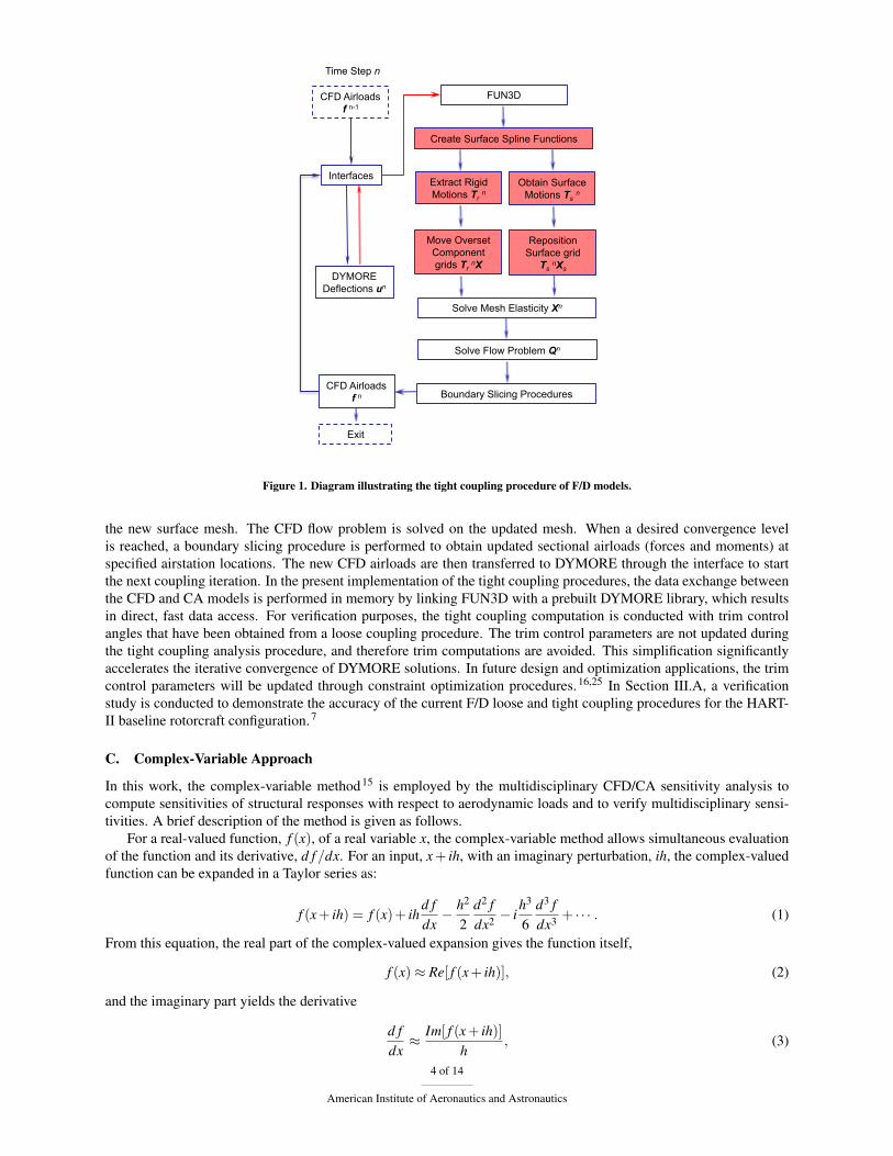
In a tight coupling approach, the CFD and CA models are still executed separately, but the data exchange occursonce per time step. Fig. 1 shows a diagram illustrating the F/D tight coupling procedures, in which FUN3D functionsthat have DYMORE structural solutions as inputs are highlighted in red. At each coupling iteration, DYMOREperforms one time-step advancement with a set of sectional airloads as inputs. The structural solutions describinglinear and angular displacements at the quarter-chord line of rotor blades are sent to FUN3D. High-order surfacespline functions are created, followed by an extraction of average rigid motions from the CA displacements and areposition of the CFD surface grid. The CFD volume grid is rigidly moved and elastically deformed to accommodate
3 of 14
American Institute of Aeronautics and Astronautics
Time Step n
CFD Airloads f n-1
Interfaces
FUN3D
Create Surface Spline Functions
Obtain Surface Motions Ts n
Extract Rigid Motions Tr n
Reposition Surface grid
Ts nXs
Move Overset Component grids Tr nX
Solve Mesh Elasticity Xn
DYMORE Deflections un
Solve Flow Problem Qn
CFD Airloads f n Boundary Slicing Procedures
Exit
Figure 1. Diagram illustrating the tight coupling procedure of F/D models.
the new surface mesh. The CFD flow problem is solved on the updated mesh. When a desired convergence levelis reached, a boundary slicing procedure is performed to obtain updated sectional airloads (forces and moments) atspecified airstation locations. The new CFD airloads are then transferred to DYMORE through the interface to startthe next coupling iteration. In the present implementation of the tight coupling procedures, the data exchange betweenthe CFD and CA models is performed in memory by linking FUN3D with a prebuilt DYMORE library, which resultsin direct, fast data access. For verification purposes, the tight coupling computation is conducted with trim controlangles that have been obtained from a loose coupling procedure. The trim control parameters are not updated duringthe tight coupling analysis procedure, and therefore trim computations are avoided. This simplification significantlyaccelerates the iterative convergence of DYMORE solutions. In future design and optimization applications, the trimcontrol parameters will be updated through constraint optimization procedures.16,25 In Section III.A, a verificationstudy is conducted to demonstrate the accuracy of the current F/D loose and tight coupling procedures for the HART-II baseline rotorcraft configuration.7
C. Complex-Variable Approach
In this work, the complex-variable method15 is employed by the multidisciplinary CFD/CA sensitivity analysis tocompute sensitivities of structural responses with respect to aerodynamic loads and to verify multidisciplinary sensi-tivities. A brief description of the method is given as follows.
For a real-valued function, f (x), of a real variable x, the complex-variable method allows simultaneous evaluationof the function and its derivative, d f /dx. For an input, x+ ih, with an imaginary perturbation, ih, the complex-valuedfunction can be expanded in a Taylor series as:
f (x+ ih) = f (x)+ ihd fdx� h2
2d2 fdx2 � i
h3
6d3 fdx3 + · · · . (1)
From this equation, the real part of the complex-valued expansion gives the function itself,
f (x)⇡ Re[ f (x+ ih)], (2)
and the imaginary part yields the derivative
d fdx⇡ Im[ f (x+ ih)]
h, (3)
4 of 14
American Institute of Aeronautics and Astronautics
with a truncation error O(h2).Unlike a finite-difference method with a real-valued perturbation, the complex-variable approach does not suffer
from subtractive cancellation errors, thereby providing increased accuracy and robustness. Within machine accuracy,derivatives computed by the complex-variable method with perturbation h = 10�50 can be considered as the truederivatives with zero truncation error.
The standard FUN3D software suite allows for complex-mode operation to verify hand-differentiated sensitivities,but a similar capability was not available in DYMORE. For the present study, a complex mode has been developed inDYMORE by replacing all double and float variables declared in the original (i.e., real-valued) DYMORE code withcomplex variables of double precision and redefining operators needed for complex-valued operations. The complexmode of DYMORE enables the evaluation of comprehensive analysis sensitivities via the complex-variable approach.The F/D interface has been extended to operate in the complex mode, supporting the exchange of complex-valuedaerodynamic forces, moments and surface displacements.
D. Sensitivity Analysis
A mathematical formulation for the sensitivities of a tight coupling multidisciplinary CFD/CA analysis is given in thissection. The following notations are used: un is a CA solution vector at a given time level n. The vector is used toupdate the surface position and the average rigid motion of component CFD grids at time level n. Initial CA solution,u0, is given as a solution of a loose coupling formulation and is independent of design parameters. A vector of airloads,fn, is computed by the CFD code at time level n at specified airstations. The fixed baseline volume and surface grids,X and Xs, are generated based on the baseline blade configuration, independent of design parameters, and used tospecify the baseline elasticity matrix, K,
K X = Xs. (4)
The reference component volume and surface grids, X and Xs, account for variations of shape design parameters (usedto perturb the surface geometry), D, and define the reference frame. The reference blade grid X is computed by solvinga mesh elasticity problem
KX = Xs(D). (5)
The overset volume and surface grids, Xn and Xns , reflect the actual positions of all blades at time level n. The initial
grid, X0, corresponding to time level n = 0 is computed by rigidly moving the reference blade grid to the correspondinginitial position for each blade and combining these component grids with a stationary background grid.
X0 = T0r X, (6)
T0r = T0(d(u0), b(u0), q(u0))Tf0 . (7)
Here, d,b, and q are lead-lag, flap, and pitch control angles, respectively; d, b, and q denote quantities averaged over theentire span of a rotor blade; T0(d(u0), b(u0), q(u0)) is an extracted (composite) rigid motion corresponding to averagedCA displacements. As described in Ref. 32, this averaged rigid motion helps keep the elastically-deflected bladecentered within the blade volume mesh, and helps prevent negative volumes during the mesh deformation process,when large flapping motions are present. The transform matrix for the composite rigid motion is obtained by successivemultiplications of the transform matrices corresponding to each rigid motion,
T(d, b, q) = T(d) · T(b) · T(q). (8)
Each rigid motion is represented as a 4⇥4 matrix
T =
2
664
R11R21R310
R12R22R320
R13R23R330
txtytz1
3
775 . (9)
Here, the 3⇥ 3 block matrix R defines a general rotation and the vector t appearing in the fourth column of thetransform matrix defines a translation. The motion Tf0 in Eq. (7) is a rigid motion transforming a blade from its initial
5 of 14
American Institute of Aeronautics and Astronautics
position to the reference frame, in which the CA displacements are defined. The grid equations at times n� 1 includeelastic grid deformations satisfying
KnXn = Tns Xs(D), (10)
Tns = Tn
yTn(d(un),b(un),q(un))Tf0 . (11)
Here, Ts denotes the elastic motions applied to individual surface nodes, and Ty is a rigid motion corresponding to theazimuthal rotation of the blades. The elasticity matrix, Kn, is derived from a rigidly moved reference grid, satisfying:
Kn Tnr X = Tn
r Xs, (12)Tn
r = Tny Tn(d(un), b(un), q(un))Tf0 . (13)
Note that the elasticity matrix at time level n relates to the baseline elasticity matrix as
Kn Tnr = Tn
r K. (14)
The vector Qn is a vector of CFD solutions at time level n. The solution at time n = 0 is specified from a precomputedloose coupling solution, Q, that may depend on CFD design parameters such as angle of attack, Mach number, etc.Given variables that are independent of design parameters, K, u0, and Tf0 , and variables that may depend on designparameters, Q(D), Xs(D), and Ty(D), the following equations for a tight coupling formulation are written in the orderin which the equations are solved:
Reference Grid : G(X, Xs,D) ⌘K X� Xs(D) = 0, (15)
Initial Grid : G0(X0, X,T0r (u0),D) ⌘X0�T0
r X = 0, (16)
Initial Flow : R0(Q0,Q(D)) ⌘Q0�Q(D) = 0, (17)
Initial Load : F0(f0, Q0,X0) =0, (18)
CA : Cn(un,un�1, fn�1,D) =0, (1 n N) (19)
CFD Grid : Gn(Xn, Xs,Tnr (un),Tn
s (un),D) ⌘Tnr K(Tn
r )�1Xn�Tn
s Xs(D) = 0, (1 n N) (20)
CFD Flow : Rn(Qn,Qn�1,Xn,Xn�1,D) =0, (1 n N) (21)Loads : Fn(fn,Qn,Xn) =fn�Sn(Qn,Xn) = 0. (1 n N) (22)
Here, S denotes a boundary slicing function performed in FUN3D for obtaining sectional airloads. For simplicity ofpresentation, the time-dependent equations are assumed to depend on solutions at the current and one preceding timelevel only. In the actual solver, the time derivatives are discretized through second-order backward difference schemesthat use solutions at the current and up to three preceding time levels. The residuals of the CFD equations are in theform of an Arbitrary Eulerian-Lagrangian formulation that is suitable for dynamic deformable grids and accounts forgrid speeds and geometric conservation law. The details of CFD equations on overset grids are provided in Ref. 25.
In the sensitivity analysis framework presented here, the CFD flow and grid equations and the loads equations useadjoint formulations, whereas sensitivities of the surface-grid elastic motion Ts and the extracted rigid motion Tr to theaerodynamic loads fn are computed by the complex-variable method. For a general objective function g(Q,u,X, f,D),the adjoint formulation is derived via the Lagrangian functional formed as
L = g(Q,u,X, f,D)+N
Ân=0
[LLLnR]T Rn +
N
Ân=0
[LLLnG]T Gn +
N
Ân=0
[LLLnF ]T Fn +
⇥LLLG
⇤T G (23)
where Q,u,X, and f represent CFD solutions, CA solutions, grid, and load solutions at all time steps, respectively; LLLR,LLLG, and LLLF are the vectors of the time-dependent adjoint solutions for the flow, grid and loads equations, respectively;LLLG denotes the adjoint solution for the reference grid; and the superscript T represents the transposition operator.Differentiating the Lagrangian with respect to design variables D and equating the coefficients of state variable sensi-tivities to zero34 yields the following adjoint equations:
6 of 14
American Institute of Aeronautics and Astronautics
for n = N,
Load :
∂g∂fN
�+⇥LLLN
F⇤T
∂FN
∂fN
�=0, (24)
Flow :
∂g∂QN
�+⇥LLLN
R⇤T
∂RN
∂QN
�+⇥LLLN
F⇤T
∂FN
∂QN
�=0, (25)
Grid :
∂g∂XN
�+⇥LLLN
G⇤T
∂GN
∂XN
�+⇥LLLN
R⇤T
∂RN
∂XN
�+⇥LLLN
F⇤T
∂FN
∂XN
�=0, (26)
for 1 n < N,
Load :
∂g∂fn
�+[LLLn
F ]T
∂Fn
∂fn
�+
N
Âk=n+1
hLLLk
G
iT "
∂Gk
∂Tkr
#"∂Tk
r
∂fn
#+
∂Gk
∂Tks
�∂Tk
s
∂fn
�!=0, (27)
Flow :
∂g∂Qn
�+[LLLn
R]T
∂Rn
∂Qn
�+⇥LLLn+1
R⇤T
∂Rn+1
∂Qn
�+[LLLn
F ]T
∂Fn
∂Qn
�=0, (28)
Grid :
∂g∂Xn
�+[LLLn
G]T
∂Gn
∂Xn
�+[LLLn
R]T
∂Rn
∂Xn
�+⇥LLLn+1
R⇤T
∂Rn+1
∂Xn
�+[LLLn
F ]T
∂Fn
∂Xn
�=0, (29)
and for n = 0,
Load :
∂g∂f0
�+⇥LLL0
F⇤T
∂F0
∂f0
�+
N
Âk=1
hLLLk
G
iT "
∂Gk
∂Tkr
#"∂Tk
r
∂f0
#+
∂Gk
∂Tks
�∂Tk
s
∂f0
�!=0, (30)
Flow :
∂g∂Q0
�+⇥LLL0
R⇤T
∂R0
∂Q0
�+⇥LLL1
R⇤T
∂R1
∂Q0
�+⇥LLL0
F⇤T
∂F0
∂Q0
�=0, (31)
Grid :
∂g∂X0
�+⇥LLL0
G⇤T
∂G0
∂X0
�+⇥LLL0
R⇤T
∂R0
∂X0
�+⇥LLL1
R⇤T
∂R1
∂X0
�+⇥LLL0
F⇤T
∂F0
∂X0
�=0, (32)
Reference Grid :⇥LLLG
⇤T"
∂G∂X
#+⇥LLL0
G⇤T
∂G0
∂X
�=0. (33)
The adjoint equations are solved in the inverse order in time. In the current implementation, [∂Fn/∂fn] is the iden-tity matrix, thus the load adjoint equation becomes a simple algebraic equation. The summation terms appearing inEqs. (27) and (30) correspond to the sensitivities of rigid motions and surface elastic motions to sectional airload vari-ations, which are computed via imaginary perturbations of individual components of the airloads fn at each time leveln. For each such perturbation, the complex-variable CA solution and the transform matrices, Tk
r and Tks , are computed
for time levels k, n kN. In contrast to the analysis procedure, in which the CA code operates on a single processor,the computations of sensitivities to airload perturbations are distributed to all the processors used in the CFD compu-tation. The total computational time for evaluating the complex-variable sensitivities is proportional to the number ofairstations that control the data exchange between the structural and aerodynamic models, the number of time stepsN, and inversely proportional to the number of processors used in parallel computing. The contributions of struc-tural sensitivities to the CFD flow and grid adjoint solutions are accounted for through the vectors [LLLn
F ]T [∂Fn/∂Qn]and [LLLn
F ]T [∂Fn/∂Xn] in the flow and grid adjoint equations, respectively. Here, [∂Fn/∂Qn] and [∂Fn/∂Xn] representthe sectional airloads sensitivities with respect to the conserved flow variables and grid solutions, respectively. Averification test for the sectional airloads sensitivities is provided in Section III.C. At time level n = 0, the matrices,[∂F0/∂f0], [∂R0/∂Q0], and [∂G0/∂X0], are identity matrices, and the load, flow and grid adjoint equations becomesimple algebraic equations.
The general form of the sensitivity derivatives of the objective function is written as:
dLdD
=
∂g∂D
�+⇥LLL0
R⇤∂G0
∂Q
�∂Q∂D
�+
N
Ân=1
[LLLnR]T
∂Rn
∂D
�+⇥LLL0
G⇤T
∂G0
∂Xs
�dXs
dD
�+
"∂G0
∂T0r
#"∂T0
r
∂D
#!(34)
+N
Ân=1
[LLLnG]T
∂Gn
∂Xs
�dXs
dD
�+
∂Gn
∂Tnr
�"∂Tn
r
∂D
#+
∂Gn
∂Tns
�∂Tn
s
∂D
�!+⇥LLLG
⇤T "
∂G∂Xs
#dXs
dD
�!.
7 of 14
American Institute of Aeronautics and Astronautics
Specifically, the sensitivity with respect to flow design parameters (e.g., angle of attack) is computed as
dLdD
=
∂g∂D
�+⇥LLL0
R⇤∂G0
∂Q
�∂Q∂D
�+
N
Ân=1
[LLLnR]T
∂Rn
∂D
�; (35)
the sensitivity with respect to shape design parameters is computed as
dLdD
=
∂g∂D
�+
N
Ân=1
[LLLnG]T
∂Gn
∂Xs
�dXs
dD
�+⇥LLLG
⇤T"
∂G∂Xs
#dXs
dD
�; (36)
the sensitivity with respect to kinematics design parameters (e.g., rotation rate) is computed as
dLdD
=
∂g∂D
�+⇥LLL0
G⇤T"
∂G0
∂T0r
#"∂T0
r
∂D
#+
N
Ân=1
[LLLnG]T
∂Gn
∂Tnr
�"∂Tn
r
∂D
#+
∂Gn
∂Tns
�∂Tn
s
∂D
�!. (37)
III. Numerical Results
This section provides verification of the current implementation of loose and tight coupling procedures for CFD/CAsystems by comparing the solutions for a test model of the baseline HART-II rotorcraft configuration7,35 with estab-lished benchmark computations and experimental data. The complex-variable analysis is verified by comparisonswith relevant real-valued, finite-difference computations. The adjoint formulation for sectional airloads computationis verified with the complex-variable approach. Sensitivities of the complete multidisciplinary CFD/CA computationsfor lift and drag functions to the angle-of-attack design parameter are presented.
A. HART-II Rotorcraft Analysis
1. CFD/CA Loose Coupling Simulations
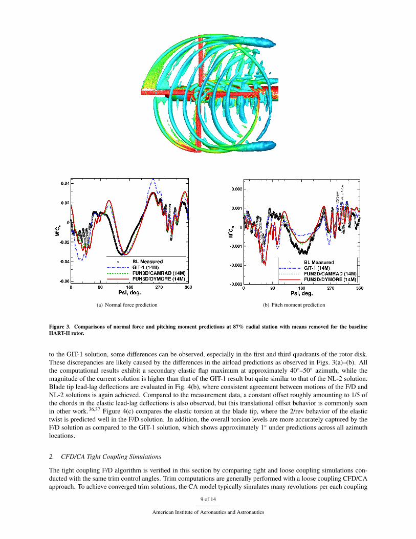
The flow conditions in the HART-II baseline case include a tip Mach number of 0.6387, an advance ratio of 0.151,and a shaft tilt angle of 4.5� (adjusted after the wind tunnel wall correction). This case represents a descending flight,where blade-vortex interactions are significant. Other important variables for the blade geometry and test conditionsare detailed elsewhere.7 Solutions for the HART-II baseline case were obtained with an unstructured mixed-elementmesh containing approximately 14 million nodes and are compared to established solutions of FUN3D/CAMRADII(NL-2)6 and a previous implementation of FUN3D/DYMORE (GIT-1)7 as well as experimental data. In the presentstudy, the BDF2opt temporal scheme is used to advance the flow computation in time with a time step correspondingto the increment of 1� azimuth angle. In ten coupling cycles that involve 5.5 revolutions, the variations in the controlangles and thrust deltas are within 0.01� and 0.1%, respectively. Figure 2 illustrates vortex structures near the HART-II rotor in the baseline case, where the BVI phenomena and the formation of blade tip vortices are clearly observed.Converged solutions of aerodynamic loading and blade tip motions are examined in the following.
Figures 3(a) and (b) demonstrate comparisons of the normal force and pitching moment at the 87% blade radialstation evaluated from the current approach (F/D), NL-2, and GIT-1 solutions, and the measurement data. The mag-nitudes and shapes of the normal force predicted by the current F/D solution are in good agreement with those of theNL-2 solutions. Furthermore, the events of BVI at the advancing side and particularly the retreating side are cap-tured well by the F/D analysis. The under prediction between 5� and 40� and the over prediction between 230� and270� appearing in the GIT-1 solution are not present in the current F/D simulation. The differences observed here arepossibly due to the fact that the present implementation of F/D coupling procedures follows closely with those of theFUN3D/CAMRADII development to date, while the GIT-1 solution was obtained with an earlier version of FUN3D,where differences exist in the global slicing procedures for extracting the blade sectional airloads and the conversionsof elastic motions to the blade surface geometries. A similar comparison is made for the aerodynamic pitching mo-ment, where the solutions of F/D, NL-2 and GIT-1 methods are generally in a good agreement, particularly in theretreating side.
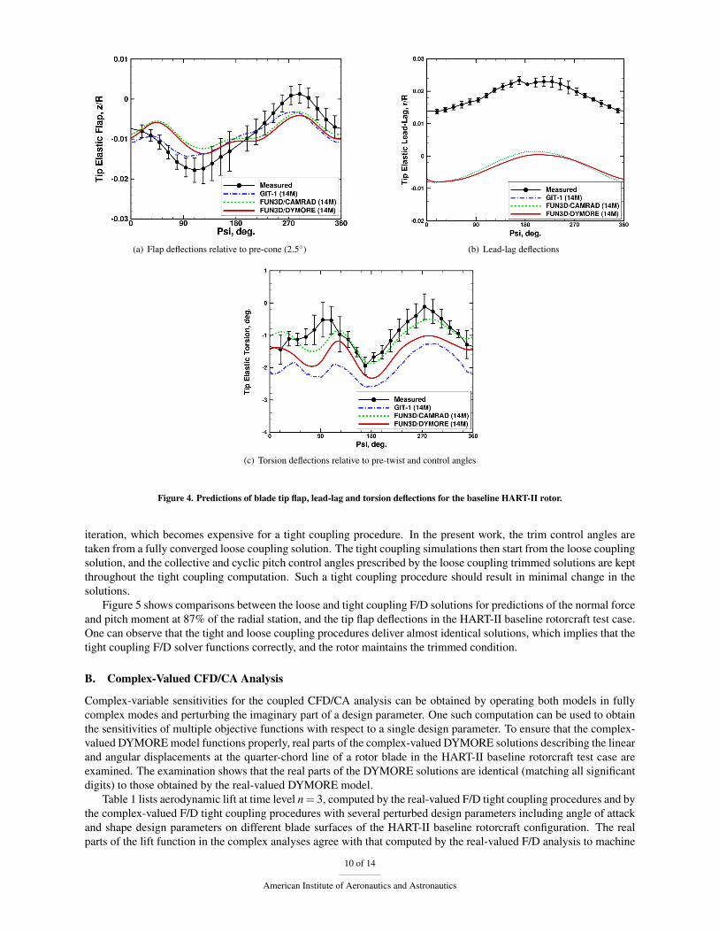
Figure 4 compares the azimuthal variation of elastic motions including flap, lead-lag and torsion deformations atthe blade tip. The flap deflections are obtained by removing the pre-cone angles (2.5�) from the vertical displace-ments, while the elastic torsion is obtained by excluding the pre-twist angles and the pitch control inputs from thetotal geometric pitch angle. As demonstrated in Fig. 4(a), the overall characteristics of the predicted blade tip flapdeflections in the F/D solution agree well with those of the NL-2 solution, both in magnitude and phase. Compared
8 of 14
American Institute of Aeronautics and Astronautics
(a) Normal force prediction (b) Pitch moment prediction
Figure 3. Comparisons of normal force and pitching moment predictions at 87% radial station with means removed for the baselineHART-II rotor.
to the GIT-1 solution, some differences can be observed, especially in the first and third quadrants of the rotor disk.These discrepancies are likely caused by the differences in the airload predictions as observed in Figs. 3(a)–(b). Allthe computational results exhibit a secondary elastic flap maximum at approximately 40�–50� azimuth, while themagnitude of the current solution is higher than that of the GIT-1 result but quite similar to that of the NL-2 solution.Blade tip lead-lag deflections are evaluated in Fig. 4(b), where consistent agreement between motions of the F/D andNL-2 solutions is again achieved. Compared to the measurement data, a constant offset roughly amounting to 1/5 ofthe chords in the elastic lead-lag deflections is also observed, but this translational offset behavior is commonly seenin other work.36,37 Figure 4(c) compares the elastic torsion at the blade tip, where the 2/rev behavior of the elastictwist is predicted well in the F/D solution. In addition, the overall torsion levels are more accurately captured by theF/D solution as compared to the GIT-1 solution, which shows approximately 1� under predictions across all azimuthlocations.
2. CFD/CA Tight Coupling Simulations
The tight coupling F/D algorithm is verified in this section by comparing tight and loose coupling simulations con-ducted with the same trim control angles. Trim computations are generally performed with a loose coupling CFD/CAapproach. To achieve converged trim solutions, the CA model typically simulates many revolutions per each coupling
9 of 14
American Institute of Aeronautics and Astronautics
(a) Flap deflections relative to pre-cone (2.5�) (b) Lead-lag deflections
(c) Torsion deflections relative to pre-twist and control angles
Figure 4. Predictions of blade tip flap, lead-lag and torsion deflections for the baseline HART-II rotor.
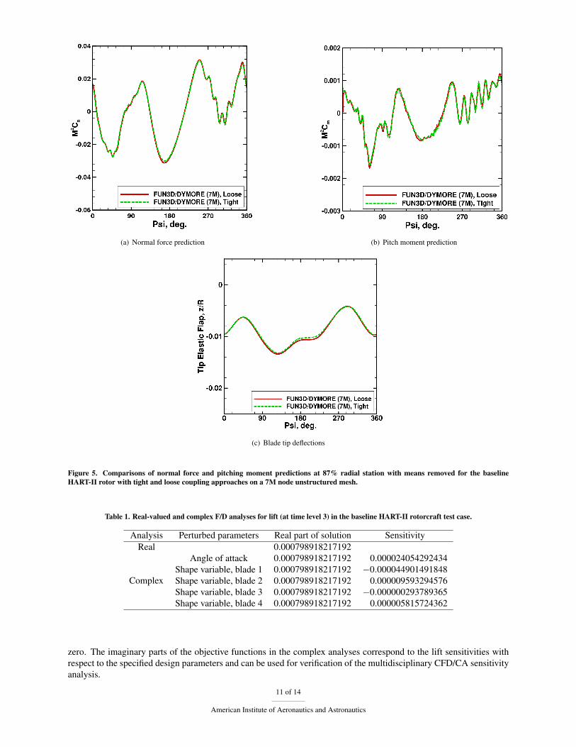
iteration, which becomes expensive for a tight coupling procedure. In the present work, the trim control angles aretaken from a fully converged loose coupling solution. The tight coupling simulations then start from the loose couplingsolution, and the collective and cyclic pitch control angles prescribed by the loose coupling trimmed solutions are keptthroughout the tight coupling computation. Such a tight coupling procedure should result in minimal change in thesolutions.
Figure 5 shows comparisons between the loose and tight coupling F/D solutions for predictions of the normal forceand pitch moment at 87% of the radial station, and the tip flap deflections in the HART-II baseline rotorcraft test case.One can observe that the tight and loose coupling procedures deliver almost identical solutions, which implies that thetight coupling F/D solver functions correctly, and the rotor maintains the trimmed condition.
B. Complex-Valued CFD/CA Analysis
Complex-variable sensitivities for the coupled CFD/CA analysis can be obtained by operating both models in fullycomplex modes and perturbing the imaginary part of a design parameter. One such computation can be used to obtainthe sensitivities of multiple objective functions with respect to a single design parameter. To ensure that the complex-valued DYMORE model functions properly, real parts of the complex-valued DYMORE solutions describing the linearand angular displacements at the quarter-chord line of a rotor blade in the HART-II baseline rotorcraft test case areexamined. The examination shows that the real parts of the DYMORE solutions are identical (matching all significantdigits) to those obtained by the real-valued DYMORE model.
Table 1 lists aerodynamic lift at time level n = 3, computed by the real-valued F/D tight coupling procedures and bythe complex-valued F/D tight coupling procedures with several perturbed design parameters including angle of attackand shape design parameters on different blade surfaces of the HART-II baseline rotorcraft configuration. The realparts of the lift function in the complex analyses agree with that computed by the real-valued F/D analysis to machine
10 of 14
American Institute of Aeronautics and Astronautics
(a) Normal force prediction (b) Pitch moment prediction
(c) Blade tip deflections
Figure 5. Comparisons of normal force and pitching moment predictions at 87% radial station with means removed for the baselineHART-II rotor with tight and loose coupling approaches on a 7M node unstructured mesh.
Table 1. Real-valued and complex F/D analyses for lift (at time level 3) in the baseline HART-II rotorcraft test case.
Analysis Perturbed parameters Real part of solution SensitivityReal 0.000798918217192
Complex
Angle of attack 0.000798918217192 0.000024054292434Shape variable, blade 1 0.000798918217192 �0.000044901491848Shape variable, blade 2 0.000798918217192 0.000009593294576Shape variable, blade 3 0.000798918217192 �0.000000293789365Shape variable, blade 4 0.000798918217192 0.000005815724362
zero. The imaginary parts of the objective functions in the complex analyses correspond to the lift sensitivities withrespect to the specified design parameters and can be used for verification of the multidisciplinary CFD/CA sensitivityanalysis.
11 of 14
American Institute of Aeronautics and Astronautics
Table 2. Comparisons of sectional airloads sensitivities with respect to the grid coordinates (y-component) and conserved flow variables(x-component of momentum) at 70% radial station via direct differentiation and complex-variable approaches.
Method ∂Fx/∂Q ∂Fy/∂Q ∂Fz/∂QAdjoint 0.000041123560446 0.000126949885201 -0.006184933414864
Complex variable 0.000041123560446 0.000126949885201 -0.006184933414864
Methods ∂Fmx/∂Q ∂Fmy/∂Q ∂Fmz/∂QAdjoint -0.000035570041307 -0.000005662910700 -0.000000350458662
Complex variable -0.000035570041307 -0.000005662910700 -0.000000350458662
Methods ∂Fx/∂X ∂Fy/∂X ∂Fz/∂XAdjoint -1.66200987502660 1.97008265283363 0.520855236517486
Complex variable -1.66200987502690 1.97008265283398 0.520855236517574
Methods ∂Fmx/∂X ∂Fmy/∂X ∂Fmz/∂XAdjoint -0.015116700097615 -0.015298667011763 0.007316138436884
Complex variable -0.015116700097618 -0.015298667011765 0.007316138436883
Table 3. Sensitivities of lift and drag to the angle-of-attack design parameter evaluated by the real-valued central difference (CD) meth-ods with perturbation sizes of 10�6 and 10�9, complex-variable approach with perturbation size of 10�50, and the coupled F/D adjointsensitivity analysis approach.
Approach Lift sensitivity Drag sensitivityReal-valued CD, h = 10�6 0.000024054294350 0.000015909433903Real-valued CD, h = 10�9 0.000024047540541 0.000015921931245
Complex variable, h = 10�50 0.000024054292434 0.000015909425336Multidisciplinary adjoint 0.000024054286300 0.000015909424183
C. Coupled CFD/CA Sensitivity Computation
The complex-variable method is employed to compute sensitivities of structural responses with respect to aerodynamicloads and relevant design parameters. All other derivatives required for the evaluation of the adjoint variables andthe final sensitivity are implemented by hand differentiation of the corresponding routines in the CFD/CA system.In this section, a verification test for sectional airloads sensitivities with respect to shape variables and conservedflow variables is performed via the complex-variable approach for the HART-II rotorcraft test example discussed inSection III.A. Table 2 shows comparisons of representative aerodynamic airloads derivatives at 70% radial stationcomputed by the hand differentiation and complex-variable approaches for a given state of viscous flow and gridsolutions. As observed, the hand-differentiated sensitivities agree with complex-variable sensitivities well; at least12-digit agreement is obtained, which is considered as a sufficiently good agreement.25
The sensitivities of aerodynamic lift and drag functions evaluated at time level n = 3 with respect to the angleof attack is computed by the multidisciplinary F/D sensitivity analysis that integrates adjoint-based sensitivities ofFUN3D and F/D interfaces with complex-variable sensitivities of DYMORE (cf. Eq. (35)). Although only the flowadjoint solutions are required in the evaluation of the sensitivity to a flow design parameter, the grid adjoint solutionsmust also be computed due to the coupling. For verification, all the time-dependent problems in both forward andadjoint analyses are converged to machine zero residuals. For demonstration purpose, the first-order backward differ-ence temporal scheme is employed in this example; other higher-order temporal schemes available in FUN3D will betested in the future work.
Table 3 lists the sensitivities of lift and drag at time level n = 3 to the angle-of-attack design parameter computed bythe real-valued finite difference (second-order central difference) methods with perturbation sizes of 10�6 and 10�9,respectively, the complex-variable approach with a perturbation size of 10�50, and the multidisciplinary F/D sensitiv-ity analysis. Compared to the complex-variable sensitivity, the real-valued finite-difference results corresponding tothe perturbation size of 10�6 show good accuracy in the estimations of lift and drag sensitivities, while the accuracydegrades significantly as the smaller perturbation size is selected. This loss of accuracy of the finite-difference deriva-tives with small perturbation size is expected due to subtractive cancellation errors, and highlights the shortcomings ofreal-valued finite differences. The multidisciplinary F/D sensitivities show good agreement with the complex-variableresults; approximately 11 digit match is achieved in both lift and drag sensitivities.
12 of 14
American Institute of Aeronautics and Astronautics
IV. Conclusions
This paper has presented a multidisciplinary sensitivity analysis framework for high-fidelity rotorcraft computa-tions conducted by a tightly coupled multidisciplinary system including a computational fluid dynamics code, FUN3D,and a rotorcraft comprehensive analysis code, DYMORE. The implementation of the current FUN3D/DYMORE(F/D) analysis procedures has been verified by simulating the baseline HART-II test model. The computed solutionsshow a good agreement with established predictions of unsteady aerodynamic airloads and various elastic deflections.Discretely-consistent adjoint formulations have been developed and verified for F/D interfaces. Structure-related sen-sitivities of deforming and rigid motions of component grids are evaluated through a complex-variable approach. Thecomplex-variable method verifies sensitivity derivatives computed with the adjoint-based methods. Complex-variableimplementation of sensitivity analysis of DYMORE and the coupled F/D system is verified by comparing with real-valued analysis and sensitivities. Results show that the blade sectional airload derivatives computed by the adjoint-based and complex-variable methods are in good agreement. Sensitivities of the lift and drag functions obtained bycomplex-variable F/D simulations are compared with sensitivities computed by the multidisciplinary sensitivity anal-ysis, which couples adjoint-based flow and grid sensitivities of FUN3D and F/D interfaces with complex-variablesensitivities of DYMORE structural responses. Future work will be concentrated on the verification of the coupledF/D multidisciplinary sensitivity analysis approach for all types of design parameters and applying it to gradient-basedmultidisciplinary optimization of rotorcraft configurations.
Acknowledgments
The work was supported by the NASA Revolutionary Vertical Lift Technology Project contract NNL15AB93T.The authors would like to thank Dr. Marilyn Smith at Georgia Institute of Technology for providing the initialFUN3D/DYMORE interface routines as well as the DYMORE input deck for the HART-II configuration. The au-thors would also like to acknowledge the support of the HART II partners from the U.S. Army Aero-Flight DynamicsDirectorate (AFDD), German Aerospace Center (DLR), German-Dutch Windtunnel (DNW), and French Aeronauticsand Space Research Center (ONERA).
References1Bauchau, O., Bottasso, C., and Nikishkov, Y., “Modeling Rotorcraft Dynamics with Finite Element Multibody Procedures,” Mathematical
and Computer Modeling, Vol. 33, 2001, pp. 1113–1137.2Johnson, W., Rotorcraft Aeromechanics, Cambridge Aerospace Series, Cambridge University Press, 2013.3Saberi, H., Khoshlahjeh, M., Ormiston, R. A., and Rutkowski, M. J., “Overview of RCAS and Application to Advanced Rotorcraft Prob-
lems,” American Helicopter Society 4th Decennial Specialists Conference on Aeromechanics.4Johnson, W., “A History of Rotorcraft Comprehensive Analyses,” NASA/TP-2012-216012, April 2012, Ames Research Center, Moffett
Field, CA.5Altmikus, A. and Wagner, S., “On the Timewise Accuracy of Staggered Aeroelastic Simulations of Rotary Wings,” AHS Aerodynamics,
Acoustics, and Test and Evaluation Specialist Meeting, San Francisco, CA, 2002.6Biedron, R. T. and Lee-Rausch, E., “Rotor Airloads Prediction Using Unstructured Meshes and Loose CFD/CSD Coupling,” AIAA Paper
2008-7341, June 2008.7Smith, M. J., Lim, J. W., van der Wall, B. G., Baeder, J. D., Biedron, R. T., Boyd Jr., D. D., Jayaraman, B., Jung, S. N., and Min, B.-Y.,
“The HART II International Workshop: An Assessment of the State of the Art in CFD/CSD Prediction,” CEAS Aeronautical Journal, Vol. 4, 2013,pp. 345–372.
8Celi, R., “Recent Applications Of Design Optimization To Rotorcraft - A Survey,” Journal of Aircraft, Vol. 36, 1999, pp. 176–189.9Walsh, J. L., Young, K. C., Tarzanin, F. J., Hirsh, J. E., and Young, D. K., “Optimization Issues with Complex Rotorcraft Comprehensive
Analysis,” AIAA Paper 1998-4889, Sept. 1998.10Murthy, T. S., “Design Sensitivity Analysis of Rotorcraft Airframe Structures for Vibration Reduction,” NASA CP 2457, NASA Langley
Research Center Sensitivity Analysis in Engineering, 1986, pp. 299–318.11Mishra, A., Mani, K., Mavriplis, D., and Sitaraman, J., “Time Dependent Adjoint-based Optimization for Coupled Fluid-Structure Prob-
lems,” Journal Computational Physics, Vol. 292, July 2015, pp. 253–271.12Wang, L., Mavriplis, D. J., and Anderson, W. K., “Adjoint Sensitivity Formulation for Discontinuous Galerkin Discretizations in Unsteady
Inviscid Flow Problems,” AIAA Journal, Vol. 48, No. 12, 2010, pp. 2867–2883.13Wang, L. and Anderson, W. K., “Shape Sensitivity Analysis for the Compressible Navier-Stokes Equations via Discontinuous Galerkin
Methods,” Computers & Fluids, Vol. 69, 2012, pp. 93–107.14Nielsen, E. J. and Diskin, B., “Discrete Adjoint-Based Design for Unsteady Turbulent Flows on Dynamic Overset Unstructured Grids,” AIAA
Journal, Vol. 51, No. 6, 2013, pp. 1355–1373.15Newman III, J. C., Anderson, W. K., and Whitfield, D. L., “Multidisciplinary Sensitivity Derivatives Using Complex Variables,” Computa-
tional Fluid Dynamics Laboratory, NSF Engineering Research Center for Computational Field Simulation, MSSU-COE-ERC-98-08, 1998.16Fabiano, E., Mavriplis, D., and Sitaraman, J., “Adjoint-based Aeroacoustics Design Optimization for Blade Vortex Interaction Noise,” AIAA
Paper 2015–1801, Jan. 2015.
13 of 14
American Institute of Aeronautics and Astronautics
17Fabiano, E. and Mavriplis, D., “Adjoint-based Aeroacoustics Design Optimization of Flexible Rotors in Forward Flight,” AHS Forum 72,West Palm Beach, FL, May 2016.
18Corliss, G., Faure, C., Griewantk, A., Hascoet, L., and Naumann, U., Automatic differentiation of algorithms: from simulation to optimiza-tion, Springer-Verlag, 2002.
19Aubert, P., Cesare, N., and Pironneau, O., “Automatic Differentiation in C++ Using Expression Templates and Application to a Flow ControlProblem,” Computing and Visualization in Science, Vol. 3, 2001, pp. 197–208.
20Martins, J. R. R. A. and Hwang, J. T., “Review and Unification of Methods for Computing Derivatives of Multidisciplinary ComputationalModels,” AIAA Journal, Vol. 51, No. 11, 2013, pp. 2582–2599.
21Anderson, W. K. and Bonhaus, D. L., “An Implicit Upwind Algorithm for Computing Turbulent Flows on Unstructured Grids,” Computers& Fluids, Vol. 23, No. 1, 1994, pp. 1–21.
22Biedron, R. T., Carlson, J.-R., Derlaga, J. M., Gnoffo, P. A., Hammond, D. P., Jones, W. T., Kleb, B., Lee-Rausch, E. M., Nielsen, E. J.,Park, M. A., Rumsey, C. L., Thomas, J. L., and Wood, W. A., “FUN3D Manual: 12.9,” NASA-TM-2016-219012, 2016.
23Noack, R., Bogar, D., Kunz, R., and Carrica, P., “SUGGAR++: An Improved General Overset Grid Assembly Capability,” AIAA Paper2009–3992, June 2009.
24Spalart, P. and Allmaras, S., “A one-equation Turbulence Model for Aerodynamic Flows,” Le Recherche Aerospatiale, Vol. 1, 1994, pp. 5–21.25Nielsen, E. J. and Diskin, B., “Discrete Adjoint-Based Design for Unsteady Turbulent Flows on Dynamic Overset Unstructured Grids,” AIAA
J., Vol. 51, No. 6, 2013, pp. 1355–1373.26Nielsen, E. J., “Adjoint-Based Aerodynamic Design of Complex Aerospace Configurations,” ASME 2016–7573, 2016.27Roe, P. L., “Approximate Riemann Solvers, Parameter Vectors, and Difference Schemes,” Journal Computational Physics, Vol. 43, No. 2,
1981, pp. 357–372.28van Leer, B., “Towards the Ultimate Conservative Difference Scheme, V. A Second Order Sequel to Godunov’s Method,” J. Com. Phys.,
Vol. 32, No. 1, 1979, pp. 101–136.29Burg, C. O. E., “Higher Order Variable Extrapolation For Unstructured Finite Volume RANS Flow Solvers,” AIAA Paper 2005–4999, 2005.30Vatsa, V., Carpenter, M. H., and Lockard, D., “Re-evaluation of An Optimized Second Order Backward Difference (BDF2OPT) Scheme for
Unsteady Flow Applications,” AIAA Paper 2010–0122, Jan. 2010.31Noack, R., “DiRTlib: A Library to Add an Overset Capability to Your Flow Solver,” AIAA Paper 2005–5116, June 2005.32Abras, J. N., Lynch, C. E., and Smith, M. J., “Computational Fluid Dynamics-Computational Structural Dynamics Rotor Coupling Using an
Unstructured Reynolds-Averaged Navier-Stokes Methodology,” Journal of The American Helicopter Society, Vol. 57, No. 012001, 2012, pp. 1–14.33Potsdam, M., Yeo, H., and Johnson, W., “Rotor Airloads Prediction Using Loose Aerodynamic/Structural Coupling,” The American Heli-
copter Society 60th Annual Forum, 2004.34Nielsen, E. J. and Anderson, W. K., “Recent Improvements in Aerodynamic Design Optimization on Unstructured Meshes,” AIAA J., Vol. 40,
No. 6, 2002, pp. 1155–1163.35van der Wall, B. G., “A Comprehensive Rotary-Wing Data Base for Code Validation: The HART II International Workshop,” The Aeronau-
tical Journal, Vol. 115, No. 1164, 2011, pp. 91–102.36Kumar, A., Viswamurthy, S. R., and Ganguli, R., “Correlation of Helicopter Rotor Aeroelastic Response with HART II Wind Tunnel Test,”
34th European Rotorcraft Forum, 2008, Liverpool, UK.37Lim, J.-W., “An Assessment of Rotor Dynamics Correlation for Descending Flight using CSD/CFD Coupled Analysis,” 64th Annual AHS
Forum, 2008, Montreal, Canada.
14 of 14
American Institute of Aeronautics and Astronautics