Seismic performance of hillside fills - eScholarshipescholarship.org/uc/item/3z84d1b6.pdf ·...
16
UC Berkeley UC Berkeley Previously Published Works Title Seismic performance of hillside fills Permalink https://escholarship.org/uc/item/3z84d1b6 Journal Journal of Geotechnical & Geoenvironmental Engineering, 127(11) Authors Stewart, Jonathan P Bray, Jonathan D McMahon, David J et al. Publication Date 2001-01-01 Peer reviewed eScholarship.org Powered by the California Digital Library University of California
Transcript of Seismic performance of hillside fills - eScholarshipescholarship.org/uc/item/3z84d1b6.pdf ·...

UC BerkeleyUC Berkeley Previously Published Works
TitleSeismic performance of hillside fills
Permalinkhttps://escholarship.org/uc/item/3z84d1b6
JournalJournal of Geotechnical & Geoenvironmental Engineering, 127(11)
AuthorsStewart, Jonathan PBray, Jonathan DMcMahon, David Jet al.
Publication Date2001-01-01 Peer reviewed
eScholarship.org Powered by the California Digital LibraryUniversity of California

SEISMIC PERFORMANCE OF HILLSIDE FILLS
By Jonathan P. Stewart,1 Jonathan D. Bray,2 David J. McMahon,3 Members, ASCE,Patrick M. Smith,4 Student Member, ASCE, and Alan L. Kropp,5 Member, ASCE
ABSTRACT: Permanent ground deformations in unsaturated, compacted hillside fills under seismic loadingconditions are discussed, with emphasis given to fill performance during the 1994 Northridge earthquake. Thesemovements represent a significant yet often unrecognized hazard to developed hillside areas, as relatively modestdeformations induced widespread damage totaling hundreds of millions of dollars during the Northridge event.The development of grading standards in the Los Angeles area is reviewed to place the seismic fill deformationproblem in context with other issues that have shaped design and construction practices for hillside fills. Fieldobservational data on fill performance during the Northridge earthquake is presented, and typical ground distresspatterns are found to include cracking near cut/fill contacts, lateral extension and settlement of fill pads, andbulging of fill slope faces. For most sites, the prevalent mechanism of permanent ground deformation responsiblefor the fill movements is contractive volumetric strain accumulation within the unsaturated fill soils during strongearthquake shaking (that is, seismic compression).
INTRODUCTION
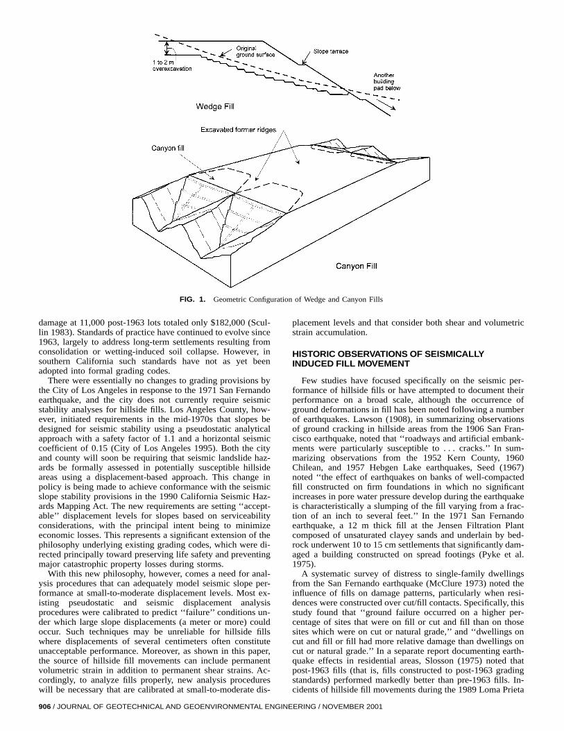
Developments in seismic design and analysis procedures forearth structures have historically been motivated by concernsabout the performance and stability of such critical facilitiesas earth dams and solid-waste landfills. This is to be expected,given the dire consequences associated with failures of suchstructures. This paper is concerned with compacted fills in de-veloped hillside areas, a class of earth structures whose seismicperformance has historically received relatively little attention,yet which are pervasive throughout urban centers in Californiaand elsewhere. These fills are constructed to create level build-ing pads, with geometric configurations similar to the wedgeand canyon fills illustrated in Fig. 1.
In California, the seismic performance of these earth struc-tures is beginning to be recognized as a critical design issue.Such concerns are derived primarily from substantial eco-nomic losses to dwellings, pipelines, and other engineered im-provements that can be traced to ground deformations in fillinduced by the 1994 Northridge earthquake. Such deforma-tions did not typically damage structures to the extent that lifesafety was threatened. However, the economic losses (mostlyborne by insurance carriers) were large as result of homeownerexpectations that damaged houses be returned to their pre-earthquake condition. The repair costs associated with suchwork typically totaled $50,000 to $100,000 per site, but oftenrose to full replacement value.
The principal objectives of this paper are to call attentionto the problem of seismically induced ground deformations incompacted fill soils and to identify the principal ground failuremechanisms responsible for such movements. The paper be-gins by providing a brief overview of grading standards in theLos Angeles area and a discussion of the degree to which thesestandards address seismic performance issues. The significanceand nature of the problem are documented using field perfor-
1Asst. Prof., Civ. and Envir. Engrg. Dept., Univ. of California, LosAngeles, CA 90095.
2Prof., Civ. and Envir. Engrg. Dept., Univ. of California, Berkeley, CA94720.
3Consultant, Berkeley, CA 94706.4Grad. Student, Civ. and Envir. Engrg. Dept., Univ. of California, Los
Angeles, CA.5Prin. Engr., Alan Kropp & Associates, Berkeley, CA 94704.Note. Discussion open until April 1, 2002. To extend the closing date
one month, a written request must be filed with the ASCE Manager ofJournals. The manuscript for this paper was submitted for review andpossible publication on October 24, 2000; revised May 14, 2001. Thispaper is part of the Journal of Geotechnical and GeoenvironmentalEngineering, Vol. 127, No. 11, November, 2001. qASCE, ISSN 1090-0241/01/0011-0905–0919/$8.00 1 $.50 per page. Paper No. 22551.
JOURNAL OF GEOTECHNICAL
mance data, principally from the 1994 Northridge earthquake.Using existing analytical methodologies, mechanisms are iden-tified that appear to explain the magnitude and pattern of de-formations at most sites. This paper is modified from an ASCEgeotechnical special publication paper (Stewart et al. 1995)with significant new field data and entirely new analyses.
SOUTHERN CALIFORNIA GRADING STANDARDS
The evolution of U.S. grading standards has historicallybeen closely linked to the state of practice in Los Angeles,where many hillside areas have been developed since WorldWar II. A number of static stability and settlement problemshave occurred in these developments, prompting the City ofLos Angeles to take a leading role in the drafting and enforce-ment of grading codes.
Before World War II, hillside development in Los Angelesoccurred on a lot-by-lot basis, with most fills limited in sizeand consisting of poorly compacted soils placed with little orno site preparation. A postwar boom in hillside constructionoften involved mass grading for large housing tracts, and al-though the capacity of earth-moving equipment had improved,most fills were still of relatively low quality as no gradingcodes were in effect. Landslide and erosion damage to thesefills during heavy rains in 1951–1952 prompted the City ofLos Angeles to adopt the first grading code for a U.S. munic-ipality that year. The purpose of this and subsequent versionsof the code has been to provide for life safety and to reducethe potential for major economic (property) losses.
The early code required compaction testing of fill soils;maximum fill slope angles of 1.5H:1V (horizontal to vertical);bottom inspection of areas to receive fill (typically to observekey and bench excavations); and installation of subdrains atthe base of fills. The effectiveness of this early code was lim-ited as the code standards were not always complied with, noroutine supervision of construction was required, and profes-sional assessments of geologic hazards (such as landslides)were not required unless specifically asked for by inspectors.Changes to the grading codes were made in response to stormdamages in 1956 and 1962, and in 1963 the code was amendedto require a maximum 2H:1V fill slope angle, geologic andengineering reports addressing slope stability, and routinesupervision of construction by engineering geologists and geo-technical engineers (Scullin 1983; J. Cobarubius, personalcommunication, 1995). In addition, the modified Proctor com-paction standard (ASTM D 1557) was adopted in 1964. Thesecodes have proven effective in controlling the storm damagethey were designed to mitigate; in a major 1969 storm, damageon 37,000 lots developed before 1963 totaled $6 million, while
AND GEOENVIRONMENTAL ENGINEERING / NOVEMBER 2001 / 905
906 / JOURNAL OF GE
FIG. 1. Geometric Configuration of Wedge and Canyon Fills
damage at 11,000 post-1963 lots totaled only $182,000 (Scul-lin 1983). Standards of practice have continued to evolve since1963, largely to address long-term settlements resulting fromconsolidation or wetting-induced soil collapse. However, insouthern California such standards have not as yet beenadopted into formal grading codes.
There were essentially no changes to grading provisions bythe City of Los Angeles in response to the 1971 San Fernandoearthquake, and the city does not currently require seismicstability analyses for hillside fills. Los Angeles County, how-ever, initiated requirements in the mid-1970s that slopes bedesigned for seismic stability using a pseudostatic analyticalapproach with a safety factor of 1.1 and a horizontal seismiccoefficient of 0.15 (City of Los Angeles 1995). Both the cityand county will soon be requiring that seismic landslide haz-ards be formally assessed in potentially susceptible hillsideareas using a displacement-based approach. This change inpolicy is being made to achieve conformance with the seismicslope stability provisions in the 1990 California Seismic Haz-ards Mapping Act. The new requirements are setting ‘‘accept-able’’ displacement levels for slopes based on serviceabilityconsiderations, with the principal intent being to minimizeeconomic losses. This represents a significant extension of thephilosophy underlying existing grading codes, which were di-rected principally toward preserving life safety and preventingmajor catastrophic property losses during storms.
With this new philosophy, however, comes a need for anal-ysis procedures that can adequately model seismic slope per-formance at small-to-moderate displacement levels. Most ex-isting pseudostatic and seismic displacement analysisprocedures were calibrated to predict ‘‘failure’’ conditions un-der which large slope displacements (a meter or more) couldoccur. Such techniques may be unreliable for hillside fillswhere displacements of several centimeters often constituteunacceptable performance. Moreover, as shown in this paper,the source of hillside fill movements can include permanentvolumetric strain in addition to permanent shear strains. Ac-cordingly, to analyze fills properly, new analysis procedureswill be necessary that are calibrated at small-to-moderate dis-
OTECHNICAL AND GEOENVIRONMENTAL ENGIN
placement levels and that consider both shear and volumetricstrain accumulation.
HISTORIC OBSERVATIONS OF SEISMICALLYINDUCED FILL MOVEMENT
Few studies have focused specifically on the seismic per-formance of hillside fills or have attempted to document theirperformance on a broad scale, although the occurrence ofground deformations in fill has been noted following a numberof earthquakes. Lawson (1908), in summarizing observationsof ground cracking in hillside areas from the 1906 San Fran-cisco earthquake, noted that ‘‘roadways and artificial embank-ments were particularly susceptible to . . . cracks.’’ In sum-marizing observations from the 1952 Kern County, 1960Chilean, and 1957 Hebgen Lake earthquakes, Seed (1967)noted ‘‘the effect of earthquakes on banks of well-compactedfill constructed on firm foundations in which no significantincreases in pore water pressure develop during the earthquakeis characteristically a slumping of the fill varying from a frac-tion of an inch to several feet.’’ In the 1971 San Fernandoearthquake, a 12 m thick fill at the Jensen Filtration Plantcomposed of unsaturated clayey sands and underlain by bed-rock underwent 10 to 15 cm settlements that significantly dam-aged a building constructed on spread footings (Pyke et al.1975).
A systematic survey of distress to single-family dwellingsfrom the San Fernando earthquake (McClure 1973) noted theinfluence of fills on damage patterns, particularly when resi-dences were constructed over cut/fill contacts. Specifically, thisstudy found that ‘‘ground failure occurred on a higher per-centage of sites that were on fill or cut and fill than on thosesites which were on cut or natural grade,’’ and ‘‘dwellings oncut and fill or fill had more relative damage than dwellings oncut or natural grade.’’ In a separate report documenting earth-quake effects in residential areas, Slosson (1975) noted thatpost-1963 fills (that is, fills constructed to post-1963 gradingstandards) performed markedly better than pre-1963 fills. In-cidents of hillside fill movements during the 1989 Loma Prieta
EERING / NOVEMBER 2001

earthquake have been reported by several consultants; how-ever, this information has not been compiled, and relativelylittle published information is available.
OBSERVATIONS FROM 1994NORTHRIDGE EARTHQUAKE
The locations of about 250 sites where fill movementscaused significant damage are shown in Fig. 2. The most con-centrated damage occurred on the north flank of the SantaMonica Mountains (for example, Sherman Oaks, Encino, Tar-zana, and Woodland Hills), along the north rim of the SanFernando Valley (Porter Ranch and Granada Hills), and in theSanta Clarita Valley area. Other affected areas included thesouth flank of the Santa Monica Mountains and portions ofSimi Valley. Geotechnical conditions and damage statistics for85 well-documented sites are presented in the Appendix. Thesedata were typically generated by consulting engineers or ge-ologists in response to insurance claims. As such, the dataprovide a somewhat biased sample by which to assess fill per-formance (that is, sites for which no claims were made are notincluded). Moreover, the data from most sites consist of gen-eral descriptions of distress and relative movements across im-provements (such as houses), but typically lack a sound basisfor assessments of absolute movements (that is, there is usuallyno ‘‘fixed’’ reference frame against which to measure totalmovements). Nonetheless, taken collectively, the data providea fairly comprehensive picture of the types of ground defor-mations that occurred in fill and the effect of such deforma-tions on structures.
Sherman Oaks
The hillside areas of Sherman Oaks have a blend of wedgefills dating from before and after the 1963 grading code. Most
JOURNAL OF GEOTECHNICAL
of these fills are less than 6 to 9 m thick and are underlain bybedrock of the Modelo formation (Tertiary-age bedded sand-stones, siltstones, and claystones). Concentrated structural dis-tress and pipe breakage occurred in this area, with approxi-mately 70 to 80 severely damaged (red-tagged) structures and80 to 90 pipe breaks in the water distribution system (Stewartet al. 1996). Some of this damage has been attributed to land-slides, often along bedding planes in the Modelo bedrock (Tan1994). However, permanent fill deformations in the area weremore widespread and appear to have been an important factorin much of the damage.
Overall, 56 documented fill movement sites have been com-piled to date (although many more sites are known to havebeen affected), with ground cracks at most sites having verticaland horizontal offsets of less than 8 cm (although overall struc-ture differential settlements of about 15 to 20 cm occurred inseveral houses). These movements damaged houses, pools,and patios and occurred in fills of both modern and older (pre-1963) construction, with no clear variations in damage inten-sity based on fill age. Several deaths were caused in the areaby the collapse of stilt-supported homes constructed over a fillslope 18 m in height dating from the 1960s. However, thesefailures have been attributed to structural deficiencies and arenot thought to have resulted directly from fill deformations.
Encino, Tarzana, and Woodland Hills
Postwar development of the north flank of the Santa MonicaMountains west of Interstate (I) 405 progressed gradually tothe west through Encino, Tarzana, and Woodland Hills, awayfrom downtown Los Angeles. Most of the fills in Encino datefrom the 1950s to early 1960s and consist of relatively shallow(<6 m thick) wedges with 1.5–2H:1V slope faces over Modelobedrock. The fills in Tarzana and Woodland Hills date pri-
FIG. 2. Locations of Sites Significant Damaged due to Fill Deformations during 1994 Northridge Earthquake (In Total, Several Thousand Sites WereAffected)
AND GEOENVIRONMENTAL ENGINEERING / NOVEMBER 2001 / 907
marily from the late 1950s to early 1960s and 1970s to 1980s,respectively. These fills share similar geometric characteristicswith the Encino fills, although some relatively deep fills (10–15 m) are also present. Damage intensities in these areas, asindexed by red-tagged structures (40) and pipe breaks (about120 to 130), were less severe than in Sherman Oaks (Stewartet al. 1996). Fifty fill movement sites have been documentedto date in this region, many of which occurred in areas ofconcentrated pipe breakage or structural damage. Surprisingly,damages were more pronounced in the relatively modern Tar-zana and Woodland Hills developments than in Encino. Doc-umented fill movements in these areas generally involvedground cracks having about 1 to 8 cm of horizontal or verticaldisplacement. Ground-floor manometer surveys indicatedoverall house differential settlements of up to 13 cm.
Porter Ranch and Granada Hills
Development in the Porter Ranch and Granada Hills areashas primarily occurred since the early 1960s. Fills in theseareas vary from essentially level fills on broad alluvial planesto deep canyon fills. Structural damage and pipe breakage pat-terns in portions of this region were unusually severe; how-ever, the most concentrated of these damages resulted fromground failure in natural soils (Stewart et al. 1996). Fewer than20 incidents of damaging fill deformations have been docu-mented to date in the region. At several sites developed in1963, fill movements involved 10 to 20 cm horizontal andvertical crack offsets in 5 to 9 m thick wedge fills. Movementsin more recent fills were generally smaller, typically involvingground cracks with horizontal and vertical displacements lessthan 5 cm.
Santa Clarita Area
Development in the Santa Clarita Valley has occurred acrossa variety of terrain ranging from alluvial plains to deep can-yons. Based on data compiled to date, portions of Santa Claritahaving significant fill movements included
• West of I-5: This area has primarily been developed sincethe mid-1980s and has many 6 to 12 m thick, single- andmultiple-pad wedge fills with 1.5–2H:1V slope faces. Thefills often directly overlie primarily Tertiary-age Saugusbedrock (sandstone and siltstone). Movements in thesefills resulted in up to 5 cm crack offsets and caused up to5 cm total differential settlements in houses. A 0.9 haschool site on a canyon fill in this area is of particularinterest because seismic deformations were quantified bypre- and post-earthquake surveys. Fill depths range from15 to 30 m, and all fill was compacted at water contentsgreater than the optimum from the modified Proctor stan-dard. The fill materials consist of silty sands (% fines '40–50; PI < 5). The magnitude of surface deformationsin areas where the fill was relatively densely compacted(modified Proctor relative compaction > 95%) were sig-nificantly smaller than the deformations in adjacent areaswith lower levels of compaction (>90%). Using the ob-served settlement data, Stewart and Smith (1998) esti-mated average volumetric strains as 0.05–0.1% in 95%RC fill and 0.5% in 90% RC fill.
• Valencia south of McBean Parkway: This area is locatedon a ridge of uplifted Pleistocene terrace deposits and wasdeveloped primarily from the late 1960s to 1970s. Single-pad wedge fills 5 to 9 m thick had extension cracks upto 10 to 30 cm wide, although 3 to 8 cm crack widthswere more typical.
• Santa Clara River area: Shallow (<3 m thick) wedge fillsin areas near the river overlie liquefiable alluvium.
908 / JOURNAL OF GEOTECHNICAL AND GEOENVIRONMENTAL ENGIN
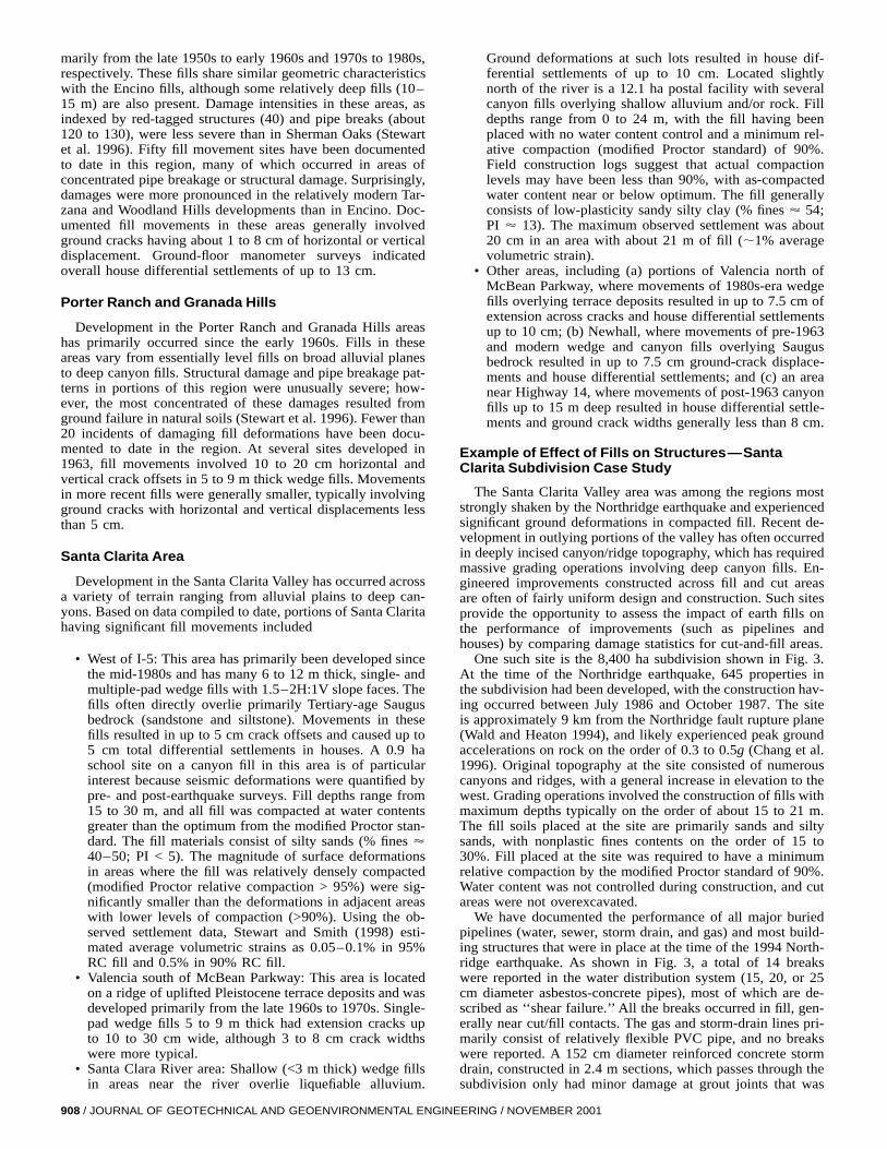
Ground deformations at such lots resulted in house dif-ferential settlements of up to 10 cm. Located slightlynorth of the river is a 12.1 ha postal facility with severalcanyon fills overlying shallow alluvium and/or rock. Filldepths range from 0 to 24 m, with the fill having beenplaced with no water content control and a minimum rel-ative compaction (modified Proctor standard) of 90%.Field construction logs suggest that actual compactionlevels may have been less than 90%, with as-compactedwater content near or below optimum. The fill generallyconsists of low-plasticity sandy silty clay (% fines ' 54;PI ' 13). The maximum observed settlement was about20 cm in an area with about 21 m of fill (;1% averagevolumetric strain).
• Other areas, including (a) portions of Valencia north ofMcBean Parkway, where movements of 1980s-era wedgefills overlying terrace deposits resulted in up to 7.5 cm ofextension across cracks and house differential settlementsup to 10 cm; (b) Newhall, where movements of pre-1963and modern wedge and canyon fills overlying Saugusbedrock resulted in up to 7.5 cm ground-crack displace-ments and house differential settlements; and (c) an areanear Highway 14, where movements of post-1963 canyonfills up to 15 m deep resulted in house differential settle-ments and ground crack widths generally less than 8 cm.
Example of Effect of Fills on Structures—SantaClarita Subdivision Case Study
The Santa Clarita Valley area was among the regions moststrongly shaken by the Northridge earthquake and experiencedsignificant ground deformations in compacted fill. Recent de-velopment in outlying portions of the valley has often occurredin deeply incised canyon/ridge topography, which has requiredmassive grading operations involving deep canyon fills. En-gineered improvements constructed across fill and cut areasare often of fairly uniform design and construction. Such sitesprovide the opportunity to assess the impact of earth fills onthe performance of improvements (such as pipelines andhouses) by comparing damage statistics for cut-and-fill areas.
One such site is the 8,400 ha subdivision shown in Fig. 3.At the time of the Northridge earthquake, 645 properties inthe subdivision had been developed, with the construction hav-ing occurred between July 1986 and October 1987. The siteis approximately 9 km from the Northridge fault rupture plane(Wald and Heaton 1994), and likely experienced peak groundaccelerations on rock on the order of 0.3 to 0.5g (Chang et al.1996). Original topography at the site consisted of numerouscanyons and ridges, with a general increase in elevation to thewest. Grading operations involved the construction of fills withmaximum depths typically on the order of about 15 to 21 m.The fill soils placed at the site are primarily sands and siltysands, with nonplastic fines contents on the order of 15 to30%. Fill placed at the site was required to have a minimumrelative compaction by the modified Proctor standard of 90%.Water content was not controlled during construction, and cutareas were not overexcavated.
We have documented the performance of all major buriedpipelines (water, sewer, storm drain, and gas) and most build-ing structures that were in place at the time of the 1994 North-ridge earthquake. As shown in Fig. 3, a total of 14 breakswere reported in the water distribution system (15, 20, or 25cm diameter asbestos-concrete pipes), most of which are de-scribed as ‘‘shear failure.’’ All the breaks occurred in fill, gen-erally near cut/fill contacts. The gas and storm-drain lines pri-marily consist of relatively flexible PVC pipe, and no breakswere reported. A 152 cm diameter reinforced concrete stormdrain, constructed in 2.4 m sections, which passes through thesubdivision only had minor damage at grout joints that was
EERING / NOVEMBER 2001

JOU
RN
AL
OF
GE
OT
EC
HN
ICA
LA
ND
GE
OE
NV
IRO
NM
EN
TA
LE
NG
INE
ER
ING
/N
OV
EM
BE
R2
00
1/909
ater Pipes and Structures
FIG. 3. Plan View of Santa Clarita Subdivision Showing Fill and Cut Zones and Locations of Damaged W
TABLE 1. Damage Statistics for Subdivision as Function of SiteCondition. Indicated Are Numbers (and Percentages in Parentheses) ofLots within Each Site Category with Different Damage Levels
Sitecondition
Nodamagea
Cosmeticdamageb
Moderatedamagec
Significantdamaged Total
Cut 193 (77%) 49 (20%) 3 (1%) 5 (2%) 250Cut/fill 159 (66%) 60 (25%) 11 (4%) 12 (5%) 242Fill 100 (65%) 39 (25%) 8 (5%) 7 (5%) 154All lots 452 (70%) 148 (23%) 22 (3%) 24 (4%) 646
aNo damage. No observed distress, or no homeowner request for in-spection.
bCosmetic damage. Cracks in walls and ceilings that do not threatenstructural integrity.
cModerate damage. Cosmetic damage 1 damaged roof, chimney,floors, windows, or plumbing, suggesting some ground deformation orintense shaking.
dSignificant damage. Moderate damage 1 cracked foundation and dis-placements observed in soil, suggesting significant ground deformation.
uniformly distributed across the length of the pipe (that is, noconcentration of damage in fill areas). Apparently the strengthand stiffness of this large-diameter RC section was sufficientto resist damage associated with deformations in fill.
Damage to structures was evaluated based on inspection re-ports prepared by Los Angeles County staff within one monthof the earthquake. Inspections were made upon the request ofproperty owners seeking earthquake relief. Specific damageswere documented, such as foundation cracks, wall cracks, andcollapsed chimneys, and monetary losses were estimated.Some properties were not inspected, presumably because oflittle or no earthquake damage. Fig. 3 shows the damage levelat each site based on the four categories in Table 1. Alsoshown in Table 1 is the frequency with which the variousdamage levels were encountered in cut, fill, and cut/fill tran-sition lots. These data indicate that the likelihood of significantdamage (damage category of 2 or 3) on cut/fill or fill lots wasmore than twice that on cut lots.
The reported damage from this subdivision indicates thatthe presence of fill significantly affected the likelihood of dam-age to pipelines and building structures, as all reported pipe-line breaks occurred in fill near cut/fill transitions, and thelikelihood of significant structural damage in fill or cut/fill ar-eas was more than twice that in cut areas.
Summary of Fill Movement Characteristics
The characteristics of the fill movements in the areas dis-cussed above were similar. With the exception of the PorterRanch and Granada Hills area, fills constructed prior to andfollowing the 1963 grading provisions appeared to undergosimilar types and magnitudes of deformations. Although mod-ern fills generally were compacted to higher relative compac-tion levels than pre-1963 fills (and thus would be expected tohave less deformation), they are also significantly deeper (forexample, see slope heights in the Appendix). Thus, the simi-larity of the deformation magnitudes is not surprising. An im-portant finding from the school and post office sites in SantaClarita was that fill deformations appear to be sensitive torelative compaction and as-compacted water content. Charac-teristic fill deformation features are illustrated in Fig. 4 anddiscussed below.
• Cracks near cut/fill contacts: The most commonly ob-served location of ground cracks in building pads was atcut/fill contacts, or above the nearest bench to cut/fill con-tacts. Cut/fill cracks typically had less than 8 cm of lateralextension and 3 cm of localized differential settlement ofthe fill relative to the cut. Damage to structures crossingthese features was often significant (Fig. 5). Where in-
910 / JOURNAL OF GEOTECHNICAL AND GEOENVIRONMENTAL ENGIN
FIG. 6. Trench Log Showing Cracking Pattern near Cut/Fill Contact—Cracking Extends to Depth of about 2 m (Adapted from Seward, Con-fidential Geologic Report, 1994)
FIG. 5. Cracked Floor Slab above Cut/Fill Contact—DisplacementsAre 1.9 cm (V) and 5 cm (H)
FIG. 4. Schematic Showing Typical Damage to Fill Slope
vestigated with trenching or downhole logging (for ex-ample, Fig. 6), these cracks were found to become thinnerwith depth and could only be traced to depths of 1 to 2m. Hence, the cracks did not appear to be surface ex-pressions of shear failures along fill/native soil-rock con-tacts. In addition to this cracking in building pad areas,cracks occurred at contacts between fill slope faces andside canyon walls.
• Lateral extension in fill pad: Evidence of lateral extensionof fill pads was commonly observed in the form of tensilecracking parallel to the top of the slope and the openingof relatively large (>3 cm) separations at cold joints be-tween concrete slabs and footings (Fig. 7) or betweenpools and pool decks. These features typically involvedabout 3 to 10 cm horizontal or vertical offsets, but sig-nificantly wider cracks (<30 cm) occurred at some sites.The setback of tensile cracking from the top of slopetended to increase will fill depth, and most houses con-structed with Uniform Building Code-level setbacks (one-third slope height) were not damaged by this cracking.
• Settlement: Fill-pad settlements increased with fill depth,
EERING / NOVEMBER 2001
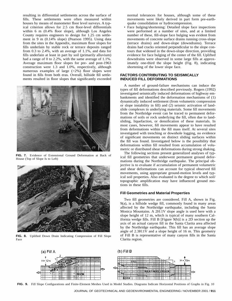
FIG. 8. Uplifted Down Drain Indicating Compression of Fill SlopeFace
FIG. 7. Evidence of Extensional Ground Deformation at Back ofHouse (Top of Slope Is to Left)
resulting in differential settlements across the surface offills. These settlements were often measured withinhouses by means of manometer floor level surveys. A typ-ical criterion allows for 2.5 cm floor-level differentialswithin 6 m (0.4% floor slope), although Los AngelesCounty requires engineers to design for 1.25 cm settle-ment in 9 m (0.14% slope) (Pearson 1995). Using datafrom the sites in the Appendix, maximum floor slopes forfills underlain by stable rock or terrace deposits rangedfrom 0.3 to 2.4%, with an average of 1.1%, and data forfills underlain at least in part by soil (primarily alluvium)had a range of 0 to 2.2%, with the same average of 1.1%.Average maximum floor slopes for pre- and post-1963construction were 1.3 and 1.0%, respectively, althoughnumerous examples of large (>2%) floor slopes werefound in fills from both eras. Overall, hillside fill settle-ments resulted in floor slopes that significantly exceeded
JOURNAL OF GEOTECHNICAL
normal tolerances for houses, although some of thesemovements were likely derived in part form pre-earth-quake consolidation or hydrocompression.
• Face bulging/shortening: Detailed slope face inspectionswere performed at a number of sites, and at a limitednumber of these, fill-slope face bulging was evident frommovements of concrete surface drains running cross-slope(terrace drains) and down-slope (downdrains). Terracedrains had cracks oriented perpendicular to the slope con-tours that widened in the down-slope direction, providingevidence for face bulging of the center of the fill. Uplifteddowndrains were observed in some large fills at approx-imately one-third the slope height (Fig. 8), indicatingshortening of the lower slope face.
FACTORS CONTRIBUTING TO SEISMICALLYINDUCED FILL DEFORMATIONS
A number of ground-failure mechanisms can induce thetypes of fill deformations described previously. Rogers (1992)investigated seismically induced deformations of highway em-bankments and identified the deformation mechanisms of (1)dynamically induced settlement (from volumetric compressionor slope instability in fill) and (2) seismic activation of land-slide complexes in underlying materials. Some fill movementsfrom the Northridge event can be traced to permanent defor-mations of soils or rock underlying the fill, often due to land-sliding, liquefaction, or densification of these materials. Inmost cases, however, fill movements appear to have resultedfrom deformations within the fill mass itself. At several sitesinvestigated with trenching or downhole logging, no evidenceof significant movements on distinct sliding surfaces withinthe fill was found. Investigated below is the possibility thatdeformations within fill resulted from accumulation of volu-metric or distributed shear deformations during strong shaking.
The following sections present generalized analyses of typ-ical fill geometries that underwent permanent ground defor-mations during the Northridge earthquake. The principal ob-jective is to evaluate if accumulation of permanent volumetricand shear deformations can account for typical observed fillmovements, using appropriate ground-motion levels and typ-ical soil properties. Also evaluated is the degree to which soil/topographic amplification may have influenced ground mo-tions in these fills.
Fill Geometries and Material Properties
Two fill geometries are considered. Fill A, shown in Fig.9(a), is a hillside wedge fill, commonly found in many areasaffected by the Northridge earthquake, including the SantaMonica Mountains. A 2H:1V slope angle is used here with aslope height of 12 m, which is typical of many southern Cal-ifornia wedge fills. Fill B [Figure 9(b)] is a 2D section up theaxis of an actual canyon fill in the Santa Clarita area affectedby the Northridge earthquake. This fill has an average slopeangle of 2.3H:1V and a slope height of 16 m. This geometryof Fill B is representative of many canyon fills in the SantaClarita region.
FIG. 9. Fill Slope Configurations and Finite-Element Meshes Used in Model Studies. Diagrams Indicate Horizontal Positions of Graphs in Fig. 10
AND GEOENVIRONMENTAL ENGINEERING / NOVEMBER 2001 / 911

Hillside fills are often underlain by relatively firm bedrockor native soils. For these analyses the material underlying thefill is assumed to be sedimentary bedrock with a surface shearwave velocity of Vs = 600 m/s, increasing to 900 m/s at adepth in rock of 10 m. This is a typical velocity profile basedon data recently compiled by the ROSRINE program (Reso-lution of Site Response Issues from the Northridge Earth-quake) for ‘‘rock’’ sites in Tertiary-age sedimentary bedrockdeposits in southern California.
Shear-strain dependent modulus reduction and materialdamping in the bedrock are modeled using curves for sand atdepths >100 m by EPRI (1993). Separate models for fill ma-terial properties are considered for Fills A and B, due to thedifferent grading standards employed during development ofthe Santa Monica Mountain and Santa Clarita locations. Therelatively modern fills in Santa Clarita (Fill B) are modeled asmoderately to well-compacted sandy materials with relativedensities of Dr ' 45 to 60% and Vs ' 200 to 300 m/s. Theolder fills in the Santa Monica Mountains (Fill A) are modeledas moderately compacted sandy materials with a relative den-sity of Dr ' 45% and Vs ' 150 to 200 m/s. These modelscorrespond roughly to relative compaction levels by the mod-ified Proctor standard of ;85 to 95% (Santa Clarita) and ;85to 90% (Santa Monica Mountains) (Lee and Singh 1971).These compaction levels are reasonably representative of thesoil properties documented in the Appendix. Shear modulusreduction and material damping in the sandy fill are modeledusing curves for sand proposed by Seed et al. (1984). Thesecurves are consistent with recent test results for southern Cal-ifornia soils by Stokoe et al. (1999) and Lanzo et al. (1997).
Ground Motions Considered
Different sets of ground motions are used here to simulateconditions for Fill A, which is representative of conditions inthe Santa Monica Mountains south of the fault rupture plane,and Fill B, which is more representative of conditions in SantaClarita, north of the fault rupture plane. Different ground mo-tions are needed for these two areas as a result of differentrupture directivity effects (for example, Somerville et al.1997), which are forward (large-amplitude pulselike motion)in Santa Clarita, and backward (lower amplitude, but longer
912 / JOURNAL OF GEOTECHNICAL AND GEOENVIRONMENTAL ENGIN
duration) in the Santa Monica Mountains. The motions se-lected for the two areas are listed in Table 2 along with keyengineering parameters describing the selected motions. Itshould be noted that the Newhall motions (Santa Clarita area)were recorded on soil and have been deconvolved with theprogram SHAKE91 (Idriss and Sun 1991) to evaluate appro-priate rock motions. All other stations were located on sedi-mentary rock site conditions or shallow soil overlying rock.The motions for Fills A and B have been scaled to have com-mon peak accelerations of 0.3 and 0.4g, respectively. Theseare typical ground motion levels in the respective areas basedon local recordings (Chang et al. 1996).
Results
Ground Motion Amplification
The analyses were performed using the finite-element pro-gram QUAD496 (Hudson and Idriss 1996), which employs atime domain solution of the equations of motion and equiva-lent linear dynamic soil modeling. The finite-element modelsemployed in the studies are shown in Fig. 9. The models wereextended 300 m in both horizontal directions from the top ofslope to minimize the effects of lateral boundary conditionson the results.
The results of these analyses support the notion of ground-motion amplification in fill. Fig. 10 shows the ground-motionamplification along the surface of the fill relative to cut (bed-rock) areas at spectral periods of T = 0 (peak acceleration); T= 0.3 s; and T = 1.0 s. Amplification in these figures is definedas the spectral acceleration on the fill surface normalized bythe median spectral acceleration of the input motions at thesame period. Amplification in Fill A (which has relatively shal-low depths of fill and a resonant period of Ts < 0.2 s) is mostpronounced at low spectral periods and is negligible at T =1.0 s. The response of Fill B is more nonlinear than that ofFill A, which is due in part to the higher peak accelerationused for scaling the Fill B motions (that is, 0.4g, as comparedto 0.3g for Fill A). The nonlinearity reduces amplification lev-els at small spectral periods (for example, T = 0 and 0.3 s),and shifts the strain-softened resonant period in the deepestpart of the fill to T ' 0.7 to 0.8 s. Accordingly, the most
TABLE 2. Earthquake Motions Used in Finite-Element Analyses
Station Sourcea r (km)b
MHAc
(g)PGVd
(cm/s) Tm(s)e Ncycf
(a) Santa Clarita Site
Newhall FS, deconvolved CSMIP 7.1 0.57 84.2 0.49 10.4Los Angeles Reservoir, abutment LADWP 7.1 0.49 56.1 0.85 3.3Pacoima, Kagel Canyon CSMIP 8.2 0.36 45.6 0.67 6.2Castaic Dam, downstream DWR 19.3 0.21 27.4 0.68 11.6Lake Piru/Santa Felecia Dam LADWP 21.4 0.23 21.9 0.57 6.1Castaic, Old Ridge Route CSMIP 22.6 0.51 48.3 0.62 5.3
(b) Santa Monica Mountains Site
Encino Dam, abutment LADWP 16.8 0.20 18.7 0.43 10.2Beverly Hills, Mullholland Dr. (1) USC 19.6 0.46 60.8 0.69 10.5Beverly Hills, Mullholland Dr. (2) USC 20.8 0.52 35.1 0.33 6.7Los Angeles, Wonderland USC 22.7 0.14 10.1 0.40 8.3Low Franklin No. 2 Dam, base LADWP 23 0.15 10.1 0.38 8.9Los Angeles, Chalon Rd. USC 23.7 0.20 21.2 0.57 10.6Los Angeles, N. Faring St. USC 23.9 0.26 21.7 0.49 7.4
Note: Santa Clarita sites have forward directivity, Santa Monica Mountains backward directivity.aCSMIP = California Strong Motion Instrumentation Program; LADWP = City of Los Angeles, Department of Water and Power (C. Davis, personal
communication, 2000); DWR = California Department of Water Resources; USC = University of Southern California.bClosest distance to fault.cMaximum horizontal acceleration, geometric mean of two components.dPeak ground velocity, geometric mean of two horizontal components.eMean period, geometric mean of two horizontal components (Rathje et al. 1998).fNumber of equivalent cycles at 0.65 3 MHA (Liu et al. 2001).
EERING / NOVEMBER 2001
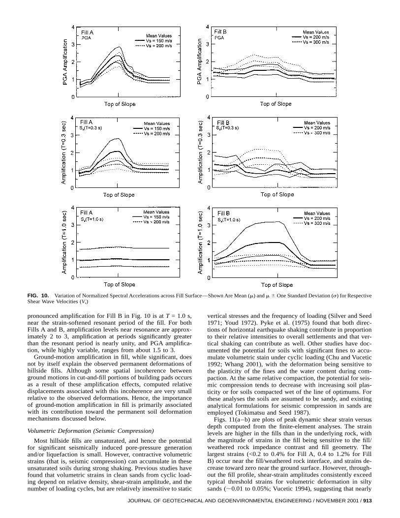
FIG. 10. Variation of Normalized Spectral Accelerations across Fill Surface—Shown Are Mean (m) and m 6 One Standard Deviation (s) for RespectiveShear Wave Velocities (Vs)
pronounced amplification for Fill B in Fig. 10 is at T = 1.0 s,near the strain-softened resonant period of the fill. For bothFills A and B, amplification levels near resonance are approx-imately 2 to 3, amplification at periods significantly greaterthan the resonant period is nearly unity, and PGA amplifica-tion, while highly variable, ranges from about 1.5 to 3.
Ground-motion amplification in fill, while significant, doesnot by itself explain the observed permanent deformations ofhillside fills. Although some spatial incoherence betweenground motions in cut-and-fill portions of building pads occursas a result of these amplification effects, computed relativedisplacements associated with this incoherence are very smallrelative to the observed deformations. Hence, the importanceof ground-motion amplification in fill is primarily associatedwith its contribution toward the permanent soil deformationmechanisms discussed below.
Volumetric Deformation (Seismic Compression)
Most hillside fills are unsaturated, and hence the potentialfor significant seismically induced pore-pressure generationand/or liquefaction is small. However, contractive volumetricstrains (that is, seismic compression) can accumulate in theseunsaturated soils during strong shaking. Previous studies havefound that volumetric strains in clean sands from cyclic load-ing depend on relative density, shear-strain amplitude, and thenumber of loading cycles, but are relatively insensitive to static
JOURNAL OF GEOTECHNICAL
vertical stresses and the frequency of loading (Silver and Seed1971; Youd 1972). Pyke et al. (1975) found that both direc-tions of horizontal earthquake shaking contribute in proportionto their relative intensities to overall settlements and that ver-tical shaking can contribute as well. Other studies have doc-umented the potential for soils with significant fines to accu-mulate volumetric stain under cyclic loading (Chu and Vucetic1992; Whang 2001), with the deformation being sensitive tothe plasticity of the fines and the water content during com-paction. At the same relative compaction, the potential for seis-mic compression tends to decrease with increasing soil plas-ticity or for soils compacted wet of the line of optimums. Forthese analyses the soils are assumed to be sandy, and existinganalytical formulations for seismic compression in sands areemployed (Tokimatsu and Seed 1987).
Figs. 11(a–b) are plots of peak dynamic shear strain versusdepth computed from the finite-element analyses. The strainlevels are higher in the fills than in the underlying rock, withthe magnitude of strains in the fill being sensitive to the fill/weathered rock impedance contrast and fill geometry. Thelargest strains (<0.2 to 0.4% for Fill A, 0.4 to 1.2% for FillB) occur near the fill/weathered rock interface, and strains de-crease toward zero near the ground surface. However, through-out the fill profile, shear-strain amplitudes consistently exceedtypical threshold strains for volumetric deformation in siltysands (;0.01 to 0.05%; Vucetic 1994), suggesting that nearly
AND GEOENVIRONMENTAL ENGINEERING / NOVEMBER 2001 / 913

FIG. 11(a). Profiles of Peak Horizontal Shear Strain with Depth in Fill A and Variation of Computed Settlement across Fill Surface Resulting formSeismic Compression (Using Tokimatsu and Seed 1987 Formulation for Clean Sand)
FIG. 11(b). Profiles of Peak Horizontal Shear Strain with Depth in Fill B and Variation of Computed Settlement across Fill Surface Resulting fromSeismic Compression (Using Tokimatsu and Seed 1987 Formulation for Clean Sand)
the full depth of the fills likely experienced volumetric strains.Volumetric strains computed from these shear strains by theTokimatsu and Seed (1987) procedure were evaluated and in-tegrated to provide the settlement profiles in Figs. 11(a–b). Asexpected, settlements increase with depth of fill, with substan-tial variations observed near cut/fill boundaries (for example,
914 / JOURNAL OF GEOTECHNICAL AND GEOENVIRONMENTAL ENGIN
near the 70 m mark in Fill A). Other key observations fromFigs. 11(a–b) are
1. The estimated settlements, which range from 0.5 to 2.0cm for Fill A and 5 to 20 cm for Fill B (mean values),are generally consistent with field observations, indicat-
EERING / NOVEMBER 2001

FIG. 12. Slip Surfaces Considered for Newmark Displacement Analysis
ing that seismic compression may be able to explainmany observed occurrences of ground deformation incompacted fills.
2. Substantial benefit is gained by increasing the compac-tion level of sandy soils, as indicated by a comparisonof the results for different Dr soils in Fig. 11(b).
Finally, it should be noted that the deformations associatedwith seismic compression occur primarily in the direction ofprincipal stress, which has a lateral component within the fillsection. Hence, the effects of seismic compression are ex-pected to consist of surface settlement and minor lateral ex-tension, which is consistent with field observations of fill padmovements.
Permanent Shear Deformations
Permanent shear deformations within a fill slope generallyoccur in the direction of a driving static shear stress (that is,downslope). As noted previously, field observations indicatedthat shear deformations were generally not localized across adistinct shear failure surface (that is, landsliding). In the ab-sence of landsliding, shear deformations can occur across adistributed zone where seismically induced shear stresses ex-ceed an effective soil yield stress. Engineers typically evaluatethe susceptibility of a slope to deformations across either dis-tinct or distributed yield zones using a Newmark analysis ofa sliding rigid block (Newmark 1965; Franklin and Chang1977) or a simplified procedure for estimating Newmark-typedisplacements that captures the dynamic response of a flexibleslide mass (for example, Makdisi and Seed 1978; Bray et al.1998). Because both calculate sliding of a block along a dis-tinct sliding surface, they do not model the actual deformationprocess and only provide an index of performance.
The potential for distributed shear deformations in Fills Aor B are assessed here using a sliding block analysis, whichrequires time histories of horizontal equivalent acceleration(HEA) for a potential sliding mass (that is, material above anassumed slip surface). The HEA time histories were calculatedusing QUAD496 for the recordings listed in Table 2 and theslip surfaces depicted in Fig. 12. The ranges of maximum hor-
JOURNAL OF GEOTECHNICAL
izontal equivalent acceleration (MHEA/g = kmax) from theseanalyses are indicated in Fig. 12. Also shown on Fig. 12 areranges of yield coefficients (ky) for these surfaces using ma-terial strengths of c = 5 kPa and f = 32 to 38 degrees. Thesingle surface shown for Fill A and Surface 1 for Fill B arethe critical surfaces for static and seismic stability using thesestrength parameters. Seismically induced shear displacementsacross the indicated range of ky were calculated using theseHEA time histories and the Franklin and Chang (1977) pro-cedure. The calculated displacements were <0.01 cm for FillA and for Surfaces 2 to 3 in Fill B, and were <1 cm for Surface1 in Fill B. These small displacements suggest that permanentshear deformations were unlikely to have contributed signifi-cantly to observed deformation patterns across the developedportions of fills having geometries similar to those investigatedhere. In the absence of such shear deformations, observed fillpad movements are most likely explained by seismic com-pression in fill.
CONCLUSIONS
Earthquake-induced deformations of hillside fills representa problem with significant economic ramifications to devel-oped hillside areas in seismically active regions. Duringthe 1994 Northridge earthquake, fill deformations damagedthousands of residences, resulting in economic losses totalinghundreds of millions of dollars. Characteristic fill deformationsfrom the Northridge event consisted of cracking at cut/fill con-tacts and lateral extension and settlement in fill. Localizedhorizontal and vertical crack offsets from these deformationswere typically less than 8 cm. These types of movements,coupled with possible ground-motion amplification in fill,were found to cause significantly greater damage in fill areasthan in cut areas in a large subdivision in Santa Clarita. Datafrom sites with known amounts of fill movement indicate suchdeformations are sensitive to the relative compaction of the filland can occur in clean sands as well as fills with significantfines content.
The pseudostatic seismic landslide analysis procedures usedto design some of these slopes were ‘‘correct’’ to the extent
AND GEOENVIRONMENTAL ENGINEERING / NOVEMBER 2001 / 915

that significant landsliding along well-defined slip surfaceswas generally not observed. However, these analyses, as wellas more sophisticated Newmark-type sliding block analyses,cannot predict the ground deformations and distress patternsobserved at the majority of sites. Rather, the primary cause ofthe observed ground deformations appears to have been seis-mic compression in fill, which has largely been ignored in thedesign of residential fills. The potential for seismic compres-sion can be evaluated using currently available procedures ina three-step approach: (1) calculate dynamic shear strains infill (using either ground response analyses such as QUAD496or SHAKE91 or simplified procedures such as those in Toki-matsu and Seed 1987); (2) evaluate volumetric strains know-ing shear-strain amplitude and equivalent number of uniformstrain cycles [using published results for clean sands (Silver
916 / JOURNAL OF GEOTECHNICAL AND GEOENVIRONMENTAL ENGIN
and Seed 1971) or soils with fines (Whang 2001), or material-specific laboratory testing]; and (3) integrate volumetric strainsto estimate surface displacements. Additional calibrations ofthis simplified approach are warranted.
While standards of practice in California are evolving tomore rationally consider seismic slope instability from shearfailures (largely as a result of the seismic slope stability pro-visions in the 1990 California Seismic Hazards Mapping Act),significant additional progress is needed in the developmentand implementation of robust procedures for evaluating seis-mic compression. It is hoped that the documentation of actualground deformations in hillside areas provided here will in-crease the awareness of this important seismic hazard amongpractitioners and regulators and aid in the development of ef-fective design and mitigation measures.
EERING / NOVEMBER 2001
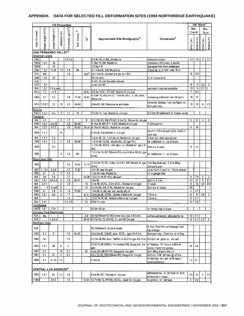
APPENDIX. DATA FOR SELECTED FILL DEFORMATION SITES (1994 NORTHRIDGE EARTHQUAKE)
JOURNAL OF GEOTECHNICAL AND GEOENVIRONMENTAL ENGINEERING / NOVEMBER 2001 / 917

918 / JOU
APPENDIX. CONTINUED
RNAL OF GEOTECHNICAL AND GEOENVIRONMENTAL ENGINEERING / NOVEMBER 2001

ACKNOWLEDGMENTS
The work described herein was funded by the National Science Foun-dation under Grant No. CMS-9416510, the Lifelines Program in the Pa-cific Earthquake Engineering Research Center under Award No. Z-19-2-133-96, and the U.S. Geological Survey, National Earthquake HazardsReduction Program, Award No. 1434-HQ-98-GR-00037. This support isgratefully acknowledged.
REFERENCES
Bray, J. D., Rathje, E. M., Augello, A. J., and Merry, S. M. (1998).‘‘Simplified seismic design procedure for geosynthetic-lined, solid-waste landfills.’’ Geosynthetics Int., 5(1–2), 203–225.
Chang, S. W., Bray, J. D., and Seed, R. B. (1996). ‘‘Engineering impli-cations of ground motions from the Northridge earthquake.’’ Bull. Seis-mological Soc. of Am., 86(1B), S270–S288.
Chu, H.-H., and Vucetic, M. (1992). ‘‘Settlement of compacted clay in acyclic direct sample shear device.’’ Geotech. Testing J., 15(4), 371–379.
City of Los Angeles. (1995). City of Los Angeles Department of Buildingand Safety/SEAOSC Joint Task Force on Evaluating Damage Due tothe Northridge Earthquake. ‘‘Subcommittee No. 12—Soils,’’ FinalRep., February.
Electrical Power Research Institute (EPRI). (1993). ‘‘Guidelines for de-termining design basis ground motions. 1: Method and guidelines forestimating earthquake ground motion in eastern North America.’’ Rep.No. EPRI TR-102293, Palo Alto, Calif.
Franklin, A. G., and Chang, F. K. (1977). ‘‘Earthquake resistance of earthand rockfill dams.’’ Misc. Paper S-71-17, U.S. Army Engineers Water-ways Experiment Station, Vicksburg, Miss.
Hudson, M. B., and Idriss, I. M. (1996). ‘‘QUAD496: A computer pro-gram to evaluate the seismic response of soil structures using finiteelement procedures, incorporating a compliant base, and incorporatingthe segmented equivalent linear procedure.’’ Ctr. for Geotech. Model-ing, University of California, Davis.
Idriss, I. M., and Sun, J. I. (1991). ‘‘User’s manual for SHAKE91: Acomputer program for conducting equivalent linear seismic responseanalyses of horizontally layered soil deposits.’’ Ctr. for Geotech. Mod-eling, University of California, Davis.
Lanzo, G., Vucetic, M., and Doroudian, M. (1997). ‘‘Reduction of shearmodulus at small strains in simple shear.’’ J. Geotech. and Geoenvir.Engrg., ASCE, 123(11), 1035–1042.
Lawson, A. C., ed. (1908). ‘‘Minor geologic effects of the earthquake.’’California earthquake of April 18, 1906, Publ. 87, Vol. 1, Part 2, Car-negie Institution of Washington, D.C., 384–409.
Lee, K. L., and Singh, A. (1971). ‘‘Compaction of granular soils.’’ Proc.,9th Annu. Symp. on Engrg. Geol. and Soils Engrg., Boise, Idaho, 161–174.
Liu, A. H., Stewart, J. P., Abrahamson, N. A., and Moriwaki, Y. (2001).‘‘Equivalent number of uniform stress cycles for soil liquefaction anal-ysis.’’ J. Geotech. and Geoenvir. Engrg., ASCE, 127(12).
Makdisi, F. I., and Seed, H. B. (1978). ‘‘Simplified procedure for esti-mating dam and embankment earthquake-induced deformations.’’ J.Geotech. Engrg., ASCE, 104(7), 849–867.
McClure, F. E. (1973). Performance of single family dwellings in the SanFernando earthquake of February 9, 1971. NOAA, U.S. Dept. of Com-merce, May.
Newmark, N. M. (1965). ‘‘Effects of earthquakes on dams and embank-ments.’’ Geotechnique, London, 15(2), 139–160.
Pearson, D. (1995). ‘‘L.A. County ‘Section 309’ Statement.’’ Geogram,California Geotechnical Engineers Association, Placerville, Calif.
JOURNAL OF GEOTECHNICA
Pyke, R., Chan, C. K., and Seed, H. B. (1975). ‘‘Settlement of sandsunder multidirectional shaking.’’ J. Geotech. Engrg. Div., ASCE,101(4), 379–398.
Rathje, E. M., Abrahamson, N. A., and Bray, J. D. (1998). ‘‘Simplifiedfrequency content estimates of earthquake ground motions.’’ J. Geo-tech. and Geoenv. Engrg., ASCE, 124(2), 150–159.
Rogers, J. D. (1992). ‘‘Seismic response of highway embankments.’’Transp. Res. Rec. 1343, Transportation Research Board, Washington,D.C., 52–62.
Scullin, C. M. (1983). Excavation and grading code administration, in-spection, and enforcement. Prentice-Hall, Englewood Cliffs, N.J.
Seed, H. B. (1967). Soil stability problems caused by earthquakes. SoilMech. and Bituminous Mat. Res. Lab., University of California, Berke-ley, January.
Seed, H. B., Wong, R. T., Idriss, I. M., and Tokimatsu, K. (1984). ‘‘Mod-uli and damping factors for dynamic analyses of cohesionless soils.’’Rep. No. UCB/EERC-84/14, Earthquake Engrg. Res. Ctr., Universityof California, Berkeley.
Silver, M. L., and Seed, H. B. (1971). ‘‘Volume changes in sands duringcyclic loading.’’ J. Soil Mech. and Found. Div., ASCE, 97(9), 1171–1182.
Slosson, J. E. (1975). ‘‘Chapter 19: Effects of the earthquake on residen-tial areas.’’ San Fernando, California, Earthquake of 9 February 1971,Bulletin 196, California Division of Mines and Geology, SacramentoCalif.
Somerville, P. G., Smith, N. F., Graves, R. W., and Abrahamson, N. A.(1997). ‘‘Modification of empirical strong motion attenuation relationsto include the amplitude and duration effects of rupture directivity.’’Seismological Res. Letters, 68(1), 94–127.
Stewart, J. P., Bray, J. D., McMahon, D. J., and Kropp, A. L. (1995).‘‘Seismic performance of hillside fills.’’ Landslides under static anddynamic conditions—Analysis, monitoring, and mitigation, D. K. Kee-fer and C. L. Ho, eds., ASCE, New York, 76–95.
Stewart, J. P., Seed, R. B., and Bray, J. D. (1996). ‘‘Incidents of groundfailure from the Northridge earthquake.’’ Bull. Seismological Soc. ofAm., 86(1B), S300–S318.
Stewart, J. P., and Smith, P. M. (1998). Ground deformations in con-structed ground. Dept. of Civ. Engrg., University of California, LosAngeles.
Stokoe, K. H., Darendeli, M. B., Andrus, R. D., and Brown, L. T. (1999).‘‘Dynamic soil properties: Laboratory, field and correlation studies.’’Earthquake geotechnical engineering, S. Pinto, ed., Vol. 3, Balkema,Rotterdam, The Netherlands, 811–845.
Tan, S. (1994). ‘‘Landslide hazards and effects of the Northridge earth-quake of January 17, 1994, in southern part of the Van Nuys Quadran-gle, Los Angeles County, California.’’ Open File Rep. 95-02, CaliforniaDivision of Mines Geology, January.
Tokimatsu, K., and Seed, H. B. (1987). ‘‘Evaluation of settlements insands due to earthquake shaking.’’ J. Geotech. Engrg., ASCE, 113(8),861–878.
Vucetic, M. (1994). ‘‘Cyclic threshold shear strains in soils.’’ J. Geotech.Engrg., ASCE, 120(12), 2208–2228.
Wald, D. J., and Heaton, T. H. (1994). ‘‘A dislocation model of the 1994Northridge, California, earthquake determined from strong ground mo-tions.’’ Open-File Rep. 94-278, U.S. Geological Survey, Washington,D.C.
Whang, D. (2001). ‘‘Seismic compression of compacted soil.’’ PhD dis-sertation, Univ. of California, Los Angeles.
Youd, T. L. (1972). ‘‘Compaction of sands by repeated shear straining.’’J. Soil Mech. and Found. Div., ASCE, 98(7), 709–725.
L AND GEOENVIRONMENTAL ENGINEERING / NOVEMBER 2001 / 919