Seismic bearing capacity of circular footings: a yield design approach
16
Journal of Mechanics of Materials and Structures SEISMIC BEARING CAPACITY OF CIRCULAR FOOTINGS: A YIELD DESIGN APPROACH Jean Salençon, Charisis Theodorou Chatzigogos and Alain Pecker Volume 4, Nº 2 February 2009 mathematical sciences publishers
Transcript of Seismic bearing capacity of circular footings: a yield design approach

Journal of
Mechanics ofMaterials and Structures
SEISMIC BEARING CAPACITY OF CIRCULAR FOOTINGS:A YIELD DESIGN APPROACH
Jean Salençon, Charisis Theodorou Chatzigogos and Alain Pecker
Volume 4, Nº 2 February 2009
mathematical sciences publishers

JOURNAL OF MECHANICS OF MATERIALS AND STRUCTURESVol. 4, No. 2, 2009
SEISMIC BEARING CAPACITY OF CIRCULAR FOOTINGS:A YIELD DESIGN APPROACH
JEAN SALENÇON, CHARISIS THEODOROU CHATZIGOGOS AND ALAIN PECKER
As developed during the past decades, the yield design theory provides an approach to the stabilityanalysis of civil engineering structures under seismic conditions which has been often used, explicitly orimplicitly. New results related to circular footings resting on a purely cohesive soil, taking into accountthe horizontal inertia forces, are presented in this paper for practical applications to the safety coefficientto be applied to the vertical load when designing seismic foundations.
An outline of yield design theory
Just to clarify the terminology and to fix the notations, a brief outline of the yield design theory [Salencon1983; 1990] is recalled here within the three dimensional continuum mechanics framework. It aims atestimating the extreme loads that can be supported by a structure from the knowledge of its geometry,of the loading process it undergoes and of the strength criteria of its constituent materials, whateverthe physical phenomena they are related to. Since they do not refer to any data about the constitutivelaw of its materials before and at failure, the results obtained are but upper bound estimates for theactual ultimate loads and no information can be obtained regarding the displacements. With the genericnotations � and ∂� for the volume and the boundary of the system, the quasistatic loading mode of thesystem is described through a multiparameter loading vector Q with components Qi and the associateddual kinematic parameters ˆqi defining the virtual kinematic vector ˆq. The principle of virtual rates ofwork [Salencon 2001] thus takes the form: for all σ statically admissible with Q, and all U kinematicallyadmissible with ˆq, ∫
�
σ : d d�+∫6U
n · σ · [[U]] d6U = Q · ˆq, (1)
withσ 7→ Q and U 7→ ˆq linear, (2)
where the symbol “ :” denotes the double contracted product and “·” the dot product. σ stands for theCauchy stress tensor field, and d for the virtual strain rate tensor field derived from the virtual velocityfield U . Since such a field may exhibit velocity jumps [[U]] across velocity jump surfaces 6U which arepart of its definition, the second term in Equation (1) accounts for the corresponding contribution.
The same description is adopted in the case of a dynamic loading treated as a quasistatic phenomenonby incorporating the corresponding given inertia forces within the applied external forces.
Homogeneity is not assumed and the term constituent material will be used generically from now onto describe all the materials constituting the system, including the interfaces between different elements.
Keywords: seismic bearing capacity, circular footings, yield design, external approach, interaction diagrams, Tresca criterion.
427

428 JEAN SALENÇON, CHARISIS THEODOROU CHATZIGOGOS AND ALAIN PECKER
The resistance of the constituent material is defined at any point of the system through a convex strengthcriterion to be satisfied by the stress state.
When trying to determine the loads Q that can be supported by the system under the specified strengthconditions, it is clear that mathematical compatibility at any point of the system between the equilibriumequations and the material resistance conditions is necessary for a load to be supported. Such loadsgenerate the convex domain of the potentially safe loads in the Q vector space. The boundary of Kdefines the extreme loads of the system. Any stress field in equilibrium with a load Q that complieswith the strength criterion is sufficient to prove that Q ∈ K . This is the basis of the internal approach orlower bound approach to the extreme loads. Although the extreme loads are but upper bound estimatesof the actual ultimate loads of the system, it must be emphasized that since they are independent of thematerial behaviour characteristics, other than the strength criteria, and of the loading paths and loadinghistory, they are valid regardless of these data. Thus, after being assessed and through the introductionof convenient safety factors, they provide a reliable theoretical benchmark for practical applications.
The construction of stress fields that satisfy the conditions above often makes the implementation ofthe internal approach difficult. Dualization through the principle of virtual rates of work (see Equations(1) and (2)) leads to an external approach based upon the construction of kinematically admissible virtualvelocity fields. The details of the related reasoning can be found in [Salencon 1990]. The key idea isthat the material resistance may be equivalently defined through the strength criteria on the stress tensor,as indicated above, or through the associated π -functions of the strain rate d: denoting generically by Gthe domain of resistance on σ defined at a point of the system, the corresponding π-function is just thesupport function
π(d)= sup{σ ′ : d | σ ′ ∈ G}, (3)
from which we derive
π(n, [[U]])= sup{n · σ ′ · [[U]] | σ ′ ∈ G}. (4)
The π-functions are called the maximum resisting rate of work densities related to G. From thedefinition of K and through Equations (1) and (2), the fundamental inequality of the external approachis obtained in the form: For every Q ∈ K , and every kinematically admissible virtual velocity field U ,
Q · ˆq ≤∫�
π(d) d�+∫6U
π(n, [[U]]) d6U . (5)
The right side of Equation (5) is called the maximum resisting rate of work in the virtual velocity fieldU :
Prm(U)=∫�
π(d) d�+∫6U
π(n, [[U]]) d6U , (6)
while the left side of (5) is just the rate of work of all the external forces Pe(Q, U). It follows fromEquations (5) and (6) that the construction of any kinematically admissible virtual velocity field yieldsan external approximation of the boundary of K :
K ⊂ {Pe(Q, U)− Prm(U)≤ 0}, for any kinematically admissible U . (7)

SEISMIC BEARING CAPACITY OF CIRCULAR FOOTINGS: A YIELD DESIGN APPROACH 429
QiQi
QjQj
QkQk
QiQi
QjQj
QkQk
Figure 1. Internal and external approaches to the domain of potentially safe loads.
The two approaches are schematically presented in Figure 1. Important points regarding the externalapproach are:
• Tables giving the expressions of the π-functions for usually encountered criteria are available[Salencon 1983; 2002].
• For a given G the values of the π-functions are either finite or infinite depending on the values ofthe arguments d and (n, [[U]]).
• For the approach to be efficient, kinematically admissible virtual velocity fields U must be chosenin order that the values of the π -functions remain finite everywhere in O .
• The third condition has no relationship whatsoever with a constitutive law.
One may wonder how the external approach can be of any use in practical applications for the designof structures since it only provides upper bounds of the extreme loads, the practical significance of whichhas been discussed above. As a matter of fact, this is one reason for the introduction of the model factorin ultimate limit state design codes [Salencon 1994]. Independently of the partial safety factors whichdefine the design loads and design resistances to be introduced in the design procedure of the consideredstructure, derived from the nominal ones, the model factor is imposed on the resisting rate of work as awhole in order to take into account the method for the yield design analysis that is performed (say, byassessing the quality of the considered potential collapse mechanisms).
Seismic bearing capacity of a circular footing on a purely cohesive soil
Problem motivation. The problem under consideration arises from a series of field observations afterseveral major earthquakes within the last twenty-five years, which revealed a particular type of foundationfailure without the presence of liquefaction in the supporting soil layers: large permanent rotations wereobserved at the foundation level together with a zone of detachment at the soil-foundation interface andthe development of a failure mechanism within the soil volume [Mendoza and Auvinet 1988]. The samefailure mechanism was also identified experimentally [Knappett et al. 2006; Zeng and Steedman 1998].
From a theoretical point of view, one initial approach to the problem of the seismic bearing capacityis to work within the classical framework of Terzaghi’s bearing capacity formula, modifying the bearingcapacity factors in order to account for the effect of the inertia forces within the soil volume during theseismic excitation, while applying appropriate correction factors for the load eccentricity and inclination

430 JEAN SALENÇON, CHARISIS THEODOROU CHATZIGOGOS AND ALAIN PECKER
[Fishman et al. 2003; Richards et al. 1993; Sarma and Iossifelis 1990]. A second approach representsthe seismic bearing capacity of the foundation system as an ultimate surface in the space of the loadingparameters of the footing as a function of the intensity of the horizontal inertia forces in the soil volume[Paolucci and Pecker 1997a; 1997b; Pecker and Salencon 1991; Salencon and Pecker 1995a; 1995b].The results so obtained in the case of shallow strip footings were incorporated in the European normsfor earthquake-resistant design of civil engineering structures [Eurocode 1998].
This study aims at extending the analysis to the seismic bearing capacity of a shallow circular footingresting on the surface of a purely cohesive soil layer.
Definition of the seismic bearing capacity problem. A rigid circular footing with radius r resting on apurely cohesive soil half-space is considered (Figure 2). The resistance of the constituent soil is describedby the Tresca criterion with a cohesion c depending linearly on the depth (8), with c0 being the surfacecohesion and α the vertical cohesion gradient:
c = c0 = αz. (8)
In order to assess the importance of the corresponding assumption, two extreme cases are considered,namely, the classical Tresca criterion (9) and the Tresca criterion with zero resistance to tension (10):
f (σ )= |σ1− σ3| − 2c ≤ 0, (9)
f (σ )= sup{|σ1− σ3| − 2c, σ1} ≤ 0, (10)
with σ1 and σ3 being the major and minor principal stresses respectively (tensile stresses positive).The soil-footing interface is also considered to be purely cohesive and its resistance is modelled by
the Tresca criterion with no tensile resistance (zero tension cut-off). This is a deliberate choice in orderto allow for the potential creation of a zone of detachment between the footing and the soil, an essentialcharacteristic of observed seismic bearing capacity failure. The interface cohesion is considered equalto c0.
f (σ, τ )= sup{|τ | − c0, σ } ≤ 0. (11)
The quasistatic loading mode of the system is defined by means of the wrench of external forces actingon the footing due to the weight and to the inertial response of the superstructure (including the footingitself), of the unit weight of the soil, and of the intensity of the inertia forces developing within the soilmass.
Following common practice, this intensity is assumed to be uniform throughout the soil mass withvertical and horizontal components Fv and Fh. The physical validity of this assumption has already beendiscussed by various authors (for example, Pecker and Salencon [1991] suggested that, denoting by d
Figure 2. Circular shallow foundation under seismic loading on a purely cohesive soil.
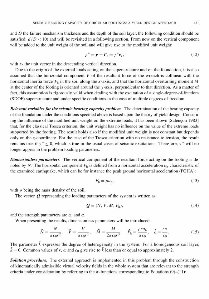
SEISMIC BEARING CAPACITY OF CIRCULAR FOOTINGS: A YIELD DESIGN APPROACH 431
and D the failure mechanism thickness and the depth of the soil layer, the following condition should besatisfied: d/D < 10) and will be revisited in a following section. From now on the vertical componentwill be added to the unit weight of the soil and will give rise to the modified unit weight:
γ ∗ = γ + Fv = γ∗ez, (12)
with ez the unit vector in the descending vertical direction.Due to the origin of the external loads acting on the superstructure and on the foundation, it is also
assumed that the horizontal component V of the resultant force of the wrench is collinear with thehorizontal inertia force Fh in the soil along the x-axis, and that the horizontal overturning moment Mat the center of the footing is oriented around the y-axis, perpendicular to that direction. As a matter offact, this assumption is rigorously valid when dealing with the excitation of a single-degree-of-freedom(SDOF) superstructure and under specific conditions in the case of multiple degrees of freedom.
Relevant variables for the seismic bearing capacity problem. The determination of the bearing capacityof the foundation under the conditions specified above is based upon the theory of yield design. Concern-ing the influence of the modified unit weight on the extreme loads, it has been shown [Salencon 1983]that, for the classical Tresca criterion, the unit weight has no influence on the value of the extreme loadssupported by the footing. The result holds also if the modified unit weight is not constant but dependsonly on the z-coordinate. For the case of the Tresca criterion with no resistance to tension, the resultremains true if γ ∗ ≤ 0, which is true in the usual cases of seismic excitations. Therefore, γ ∗ will nolonger appear in the problem loading parameters.
Dimensionless parameters. The vertical component of the resultant force acting on the footing is de-noted by N . The horizontal component Fh is defined from a horizontal acceleration ah characteristic ofthe examined earthquake, which can be for instance the peak ground horizontal acceleration (PGHA):
Fh = ρah, (13)
with ρ being the mass density of the soil.The vector Q representing the loading parameters of the system is written as
Q = (N , V,M, Fh), (14)
and the strength parameters are c0 and α.When presenting the results, dimensionless parameters will be introduced:
N =N
πc0r2 , V =V
πc0r2 , M =M
2πc0r3 , Fh =ρrah
πc0, k =
rαc0. (15)
The parameter k expresses the degree of heterogeneity in the system. For a homogeneous soil layer,k = 0. Common values of r , α and c0 give rise to k less than or equal to approximately 2.
Solution procedure. The external approach is implemented in this problem through the constructionof kinematically admissible virtual velocity fields in the whole system that are relevant to the strengthcriteria under consideration by referring to the π -functions corresponding to Equations (9)–(11):

432 JEAN SALENÇON, CHARISIS THEODOROU CHATZIGOGOS AND ALAIN PECKER
• Classical Tresca criterion (Equation (9)):
π(d)=+∞ if tr(d) 6= 0,
π(d)= c(|d1| + |d2| + |d3|) if tr(d)= 0,
π(n, [[U]])=+∞ if [[U]] · n 6= 0,
π(n, [[U]])= c|[[U]]| if [[U]] · n= 0.
(16)
• Tresca criterion with zero tension cut-off (Equation (10)):
π(d)=+∞ if tr(d) < 0,
π(d)= c(|d1| + |d2| + |d3| − tr(d)) if tr(d)≥ 0,
π(n, [[U]])=+∞ if [[U]] · n< 0,
π(n, [[U]])= c|[[U]] − [[U]] · n| if [[U]] · n ≥ 0.
(17)
• Tresca criterion for the interface without resistance to tension (Equation (11)):
π(n, [[U]])=+∞ if [[U]] · n< 0,
π(n, [[U]])= c|[[U]] − ([[U]] · n) · n| if [[U]] · n ≥ 0.(18)
It follows obviously that a relevant virtual velocity field for the classical Tresca criterion is also relevantfor the Tresca criterion without tensile strength, but not vice versa. Attention must be paid also toEquation (18) as it shows that a nonzero maximum resisting rate of work is obtained even when adetachment between the footing and the soil is induced by the virtual velocity field.
Since the circular footing is assumed to be perfectly rigid, any kinematically admissible virtual velocityU field must comply with a rigid body motion of the footing as a boundary condition. For the planarvelocity fields that will be considered hereafter, assuming Uy = 0, such a rigid body motion is definedby the virtual rate of rotation ω and the two components UO,x , UO,z of the virtual velocity of the centerO of the footing. Consequently the rate of work of the external forces is written:
Q · ˆq = NUO,z + V UO,x +Mω+ Fh
∫�
U · exd O. (19)
Three classes of kinematically admissible virtual velocity fields U have been examined, which are de-rived from plane strain potential failure mechanisms used to determine the seismic bearing capacity ofstrip footings. Completely described in [Chatzigogos 2007; Chatzigogos et al. 2007], these planar andnonplane strain virtual velocity fields are parallel to Oxz and depend on the three coordinates. They arerelevant to the strength criteria (Equations (9)–(11)) since they are isochoric everywhere in �: tr(d)= 0,[[U]] · n= 0, but for the interface where virtual uplift of the footing with respect to the soil surface mayoccur [[U]] · n ≥ 0. In order to implement the external approach through Equation (7) Prm(U) must becomputed, which implies deriving d from U , a tedious task until it was drastically simplified by Puzrinand Randolph [2003a; 2003b] in a method based upon the use of wisely chosen curvilinear coordinates.

SEISMIC BEARING CAPACITY OF CIRCULAR FOOTINGS: A YIELD DESIGN APPROACH 433
• Translational virtual failure mechanisms were originally proposed in plane strain [Green 1954] forthe indentation by a rigid punch submitted to an inclined load; the extension to a rigid circularfooting was given by Puzrin and Randolph [2003b] by considering that the width of the mechanismin a cross-section by a vertical plane is proportional to the width of the footing in the same cross-section (Figure 3). The footing translates with a virtual velocity U0 which propagates with a constantmagnitude along the streamlines of the mechanism. The shape of each virtual failure mechanismis defined by two angles: 0< δ < π/2, 0< ε < π/2. The mechanisms exhibit three zones withinthe soil mass, presented in Figure 3. Zones 1 and 3 translate rigidly while zone 2 is a region wherenonplane shear strain rate is developed. Contributions to the maximum resisting rate of work forthis class are developed within the volume of zone 2 and along the velocity jump surface in thesoil. These virtual mechanisms involve no rotation of the footing: the upper bound estimates theyprovide through (7) do not involve the moment M .
• Purely rotational virtual failure mechanisms are adapted from the plane strain version studied in[Salencon and Pecker 1995a; 1995b; Sekiguchi and Kobayashi 1997]. The rigid circular footingis considered to rotate rigidly around an axis parallel to Oy and induces rigid rotational failureof the soil below with a virtual angular velocity ω (Figure 4). Each mechanism is defined by thegeometrical parameters κ and λ. For 1 < λ < 2, there is no uplift of the footing with respect tothe soil surface and the maximum resisting rate of work is only produced along the velocity jumpsurface within the soil volume. For 0< λ < 1, uplift of the footing with respect to the soil surfacetakes place in the zone of soil-footing detachment where consequently a fraction of the maximumresisting rate of work is developed.
• Shear-rotational virtual failure mechanisms follow a pattern derived from the plane-strain virtualvelocity field originally proposed by Hansen [1953] for the study of active earth pressures (seeFigure 5).
Figure 3. Translational virtual failure mechanism.

434 JEAN SALENÇON, CHARISIS THEODOROU CHATZIGOGOS AND ALAIN PECKER
Figure 4. Purely rotational virtual failure mechanism.
Rigid body rotation of the footing around an axis of rotation parallel to Oy located within the soil massinduces the development of nonplanar shear strain rate in the zones 2 and 3 within the soil volume. Themechanisms depend on the three geometrical parameters κ , λ, µ and three distinct configurations areobtained depending on the position of the axis of rotation with respect to the footing: without uplift ofthe footing with respect to the soil surface or with a small or large zone of detachment; contributions tothe maximum resisting rate of work are developed within the soil volume in zones 2 and 3, along thevelocity jump surface in the soil mass and on the zone of soil-footing detachment, if any.
Results
Implementing the external approach through Equation (7), the rate of work of the external forces isgiven by (19) and the maximum resisting rate of work Prm(U) is computed through (6) with the relevantexpressions for π(d) and π(n, [[U]]). Looking for optimal upper bounds for the ultimate loads supportedby the system requires the implementation of an optimization procedure over each separate geometricalconfiguration of the three considered classes of virtual mechanisms: in each case, the mathematicalproblem involved reduces to minimizing a nonlinear objective function with respect to the parameters ofthe geometric configuration. The algorithm used for this purpose is described in [Coleman and Li 1996].The following results were obtained.
Figure 5. Shear-rotational virtual failure mechanism.

SEISMIC BEARING CAPACITY OF CIRCULAR FOOTINGS: A YIELD DESIGN APPROACH 435
Figure 6. Plane strain circular rigid body virtual collapse mechanism.
Critical value of Fh. The assumption of uniformly distributed horizontal inertia forces Fh would leadto a pathological conclusion if, in addition to the limitation on the ratio d/D which has already beenintroduced for physical relevance, the virtual failure mechanisms to be taken in consideration were giventhe possibility of infinite extension.
As an illustrative example, the plane strain circular rigid body virtual collapse mechanism presented inFigure 6 can be considered. In the case of a homogeneous soil layer, denoting by L and d its horizontaland vertical extension respectively, the minimization procedure on this class of mechanisms proves theinstability of the system just due to the action of the soil inertia forces if ρah > 8.3c0/L = 2.74c0/d,with the other loading parameters being zero: N = 0, V = 0, M = 0. As a consequence, for any circularfooting with radius r ≤ L/2, the value Fh = 2.64r/L = 0.87d/L would appear as the critical valuefor the considered mechanism. This critical value tends to zero if the extension of the mechanism isunlimited. The value Fh = 0 would therefore appear as the critical value of Fh, a conclusion that isobviously unrealistic! This brings us to the condition that the virtual failure mechanisms implementedin the yield design theory must be physically relevant, apart from the fact that horizontal uniformity ofFh could also be questioned. In other words, pathological circumstances are put aside through realisticconstraints on the minimization procedure on the virtual failure mechanisms.
Table 1 summarizes the calculated values of critical Fh as a function of k for the three classes ofexamined three-dimensional virtual failure mechanisms. As could be anticipated, it shows that the criticalvalue increases with k. The minimum value is obtained for the homogeneous soil (k = 0) through ashear-rotational virtual failure mechanism. For usual values of the other parameters such as r = 4 m,c0 = 20 kPa, ρ = 2× 10³ kg/m3 it corresponds to a very strong earthquake: ah = 5 m/sec2 ∼= 0.5g.
Class of mechanisms Critical value of Fhk = 0 k = 0.5 k = 1 k = 3
Translational 1.32 1.80 2.29 4.05Purely rotational 0.99 1.28 1.54 2.45Shear rotational 0.66 0.90 1.15 2.03
MINIMUM 0.66 0.90 1.15 2.03
Table 1. Critical values of Fh as a function of k.

436 JEAN SALENÇON, CHARISIS THEODOROU CHATZIGOGOS AND ALAIN PECKER
Figure 7. External approach of the ultimate load surface for a homogeneous soil (k = 0)when Fh = 0 (left) and Fh = 0.5 (right).
Presentation of the results. The upper bounds for the ultimate loads supported by the foundation arerepresented as surfaces in the space of the loading parameters (N , V , M) for different values of Fh andk (Figure 7).
Since these surfaces are obtained through the minimization procedure described earlier over threedifferent classes of virtual collapse mechanisms, they are just piecewise regular, each smooth part beingthe result of one class of mechanisms as it will appear in the interaction diagrams (Figures 8–9).
For practical applications the most convenient presentation of the results is by means of sectionsof those surfaces that may be called classically interaction diagrams: these curves represent the upperbounds for the ultimate combinations of the loading parameters and indicate the class of mechanismsfrom which each bound is obtained. In the following, the results refer to the Tresca criterion with azero tension cut-off for the soil strength which seems the most realistic criterion to be considered. Forbrevity’s sake, only some significant results will be reported here; a comprehensive and commentedreport may be found in [Chatzigogos 2007; Chatzigogos et al. 2007].
Interaction diagram (N, V , M = 0, Fh). The diagrams in Figure 8 present the relation between theultimate horizontal and vertical force for k = 0 and k = 1, for three different values of Fh. The maximumvalue for V is 1, corresponding to a translational mechanism of failure by pure sliding along the soil-footing interface when Fh = 0. It is also interesting to note that for Fh > 0 the purely rotational virtualmechanism gives an upper bound that is slightly better than the pure sliding one: although the depth ofthis mechanism is relatively small, so that it is very close to a pure sliding, it incorporates a contributionof Fh to the rate of work of the external forces. This phenomenon is less pronounced for larger valuesof k as revealed by the diagram for k = 1. For practical applications it is worth noting that, both fork = 0 and for k = 1, the effect of Fh remains negligible as long as N 0
max/N > 2.5, where N 0max denotes
the known exact value of the maximal vertical force supported by the footing with Fh = 0 [Salenconand Matar 1982]. As N increases so does the negative effect of a high value of Fh, especially whenN 0
max/N > 2i but it is observed that it is less pronounced for k = 0 than for k = 1: a favourable effect ofthe vertical cohesion gradient.
Interaction diagram (N, V , M = 0, Fh). Figure 10 presents the optimal upper bounds for the ultimatecombinations of M and N obtained with V = 0, for k = 0 and k = 1. Experimental data in the case k = 0,Fh = 0 in [Houlsby and Martin 1993] are plotted for comparison.

SEISMIC BEARING CAPACITY OF CIRCULAR FOOTINGS: A YIELD DESIGN APPROACH 437
0.0
0.2
0.4
0.6
0.8
1.0
0.0 1.0 2.0 3.0 4.0 5.0 6.0 7.0 8.0 9.0Vertical Force N
Ho
rizo
nta
l Fo
rce
V
Translational
P.R. - no uplift
P.R. - with uplift
S.R. - small uplift
Exact values
F h = 0.5
F h = 0.25
F h = 0.0
0.0
0.2
0.4
0.6
0.8
1.0
0.0 1.0 2.0 3.0 4.0 5.0 6.0 7.0 8.0 9.0
Vertical Force N
Ho
riz
on
tal
Fo
rce V
F h = 0.5
F h = 0.25
F h = 0.0
Figure 8. Interaction diagram (N , V , M = 0, Fh) for k = 0 (top) and k = 1 (bottom).Tresca criterion with zero tension cut-off.
It comes out that the upper bounds are satisfactory, from a practical point of view, and that the dif-ference is larger for the larger values of N that correspond to quasiaxisymmetric loading configurations,to which the considered unilateral virtual failure mechanisms are not well suited. For small values ofN , the optimal upper bounds are obtained by mechanisms with a significant zone of detachment of thefooting, which is not the case as N increases. The effect of Fh follows the same behaviour as in Figure 8,which, from a practical point of view, enforces the conclusion from this observation that a factor of safetyagainst permanent loads N 0
max/N > 2.5 can guarantee that the effect of soil inertia forces is negligible,even for very strong earthquakes. Such conclusions are in agreement with observations of real foundationbearing capacity failures, mainly after the Guerrero–Michoacan earthquake (Mexico, 1985) as presentedin [Mendoza and Auvinet 1988].
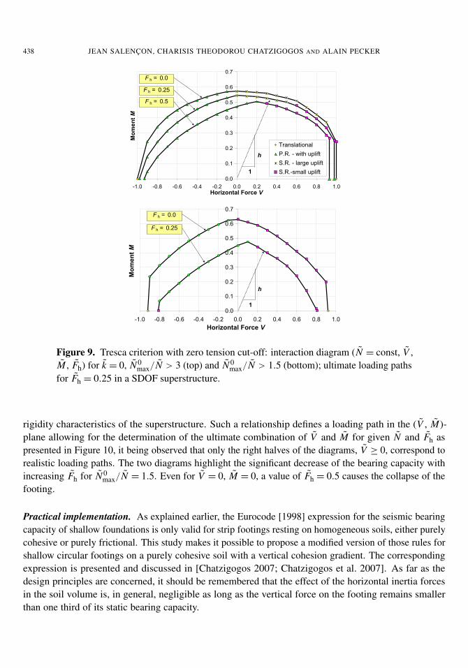
Interaction diagram (N = const, V , M, Fh ). The interaction diagrams between the ultimate values of Vand M for fixed values of the vertical force N are shown in Figure 9 for k= 0 in the two cases N 0
max/N = 3corresponding to a proper foundation design and N 0
max/N = 1.5 corresponding to a nonconservativedesign.
These diagrams can be used for practical applications when a relationship between the resultant mo-ment and the horizontal force (base shear force) on the footing is known from the geometrical and
438 JEAN SALENÇON, CHARISIS THEODOROU CHATZIGOGOS AND ALAIN PECKER
0.0
0.1
0.2
0.3
0.4
0.5
0.6
0.7
-1.0 -0.8 -0.6 -0.4 -0.2 0.0 0.2 0.4 0.6 0.8 1.0Horizontal Force V
Mo
men
t M
Translational
P.R. - with uplift
S.R. - large uplift
S.R.-small uplift
F h = 0.5
F h = 0.25
F h = 0.0
1
h
0.0
0.1
0.2
0.3
0.4
0.5
0.6
0.7
-1.0 -0.8 -0.6 -0.4 -0.2 0.0 0.2 0.4 0.6 0.8 1.0
Horizontal Force V
Mo
men
t M
F h = 0.25
F h = 0.0
1
h
Figure 9. Tresca criterion with zero tension cut-off: interaction diagram (N = const, V ,M , Fh) for k = 0, N 0
max/N > 3 (top) and N 0max/N > 1.5 (bottom); ultimate loading paths
for Fh = 0.25 in a SDOF superstructure.
rigidity characteristics of the superstructure. Such a relationship defines a loading path in the (V , M)-plane allowing for the determination of the ultimate combination of V and M for given N and Fh aspresented in Figure 10, it being observed that only the right halves of the diagrams, V ≥ 0, correspond torealistic loading paths. The two diagrams highlight the significant decrease of the bearing capacity withincreasing Fh for N 0
max/N = 1.5. Even for V = 0, M = 0, a value of Fh = 0.5 causes the collapse of thefooting.
Practical implementation. As explained earlier, the Eurocode [1998] expression for the seismic bearingcapacity of shallow foundations is only valid for strip footings resting on homogeneous soils, either purelycohesive or purely frictional. This study makes it possible to propose a modified version of those rules forshallow circular footings on a purely cohesive soil with a vertical cohesion gradient. The correspondingexpression is presented and discussed in [Chatzigogos 2007; Chatzigogos et al. 2007]. As far as thedesign principles are concerned, it should be remembered that the effect of the horizontal inertia forcesin the soil volume is, in general, negligible as long as the vertical force on the footing remains smallerthan one third of its static bearing capacity.

SEISMIC BEARING CAPACITY OF CIRCULAR FOOTINGS: A YIELD DESIGN APPROACH 439
0.0
0.1
0.2
0.3
0.4
0.5
0.6
0.7
0.8
0.9
0 1 2 3 4 5 6 7 8 9
Vertical Force N
Mo
men
t M
P.R. - no uplift
P.R. - with uplift
S.R.- small uplift
S.R. - large uplift
Exact Values
F h = 0.5
F h = 0.25
F h = 0.0
Experimental results
(Houlsby & Martin, 1992)
0.0
0.1
0.2
0.3
0.4
0.5
0.6
0.7
0.8
0.9
0 1 2 3 4 5 6 7 8 9
Vertical Force N
Mo
men
t M
F h = 0.5
F h = 0.25
F h = 0.0
Figure 10. Interaction diagram (N , V =0, M , Fh) for k=0 (top) and k=1 (bottom), andexperimental results by Houlsby and Martin [1993]. Tresca criterion with zero tensioncut-off.
Conclusion
Seismic actions must now often be taken into account when designing private or industrial buildings orstructures such as bridges, dams, nuclear plants, etc. We have briefly outlined how such a problem canbe thoroughly studied from the theoretical point of view through the yield design approach up to thewriting of new international design codes. For this purpose it is necessary that the rationale of the yielddesign theory be thoroughly understood since most (not to say all) equations that are used in such codesare obtained through the external approach, either explicitly or implicitly. To this extent the yield designtheory is a corner stone of ultimate limit state design (ULSD).
References
[Chatzigogos 2007] C. T. Chatzigogos, Comportement sismique des fondations superficielles: vers la prise en compte d’uncritère de performance dans la conception, Ph.D. thesis, École Polytechnique Palaiseau, Palaiseau, France, 2007, Available athttp://www.imprimerie.polytechnique.fr/Theses/Files/Chatzigogos.pdf.
[Chatzigogos et al. 2007] C. T. Chatzigogos, A. Pecker, and J. Salençon, “Seismic bearing capacity of a circular footing on aheterogeneous cohesive soil”, Soils Found. 47:4 (2007), 783–787.
[Coleman and Li 1996] T. F. Coleman and Y. Li, “An interior trust region approach for nonlinear minimization subject tobounds”, SIAM J. Optim. 6:2 (1996), 418–445.
[Eurocode 1998] “Calcul des structures pour leur résistance aux séismes”, EUROCODE 8, Commission Europénne de Normal-isation, 1998. Partie 5.
[Fishman et al. 2003] K. L. Fishman, R. Richards Jr., and D. Yao, “Inclination factors for seismic bearing capacity”, J. Geotech.Geoenviron. 129:9 (2003), 861–865.

440 JEAN SALENÇON, CHARISIS THEODOROU CHATZIGOGOS AND ALAIN PECKER
[Green 1954] A. P. Green, “The plastic yielding of metal junctions due to combined shear and pressure”, J. Mech. Phys. Solids2:3 (1954), 197–211.
[Hansen 1953] J. B. Hansen, Earth pressure calculation: application of a new theory of rupture to the calculation and designof retaining walls, anchor slabs, free sheet walls, anchored sheet walls, fixed sheet walls, braced walls, double sheet walls andcellular cofferdams, Danish Technical Press — Institution of Danish Civil Engineers, Copenhagen, 1953.
[Houlsby and Martin 1993] G. T. Houlsby and C. M. Martin, “Modelling of the behaviour of foundations of jack-up units onclay”, pp. 339–358 in Predictive soil mechanics, edited by G. T. Houlsby and A. N. Schofield, Thomas Telford, London, 1993.
[Knappett et al. 2006] J. A. Knappett, S. K. Haigh, and S. P. G. Madabhushi, “Mechanisms of failure for shallow foundationsunder earthquake loading”, Soil Dyn. Earthq. Eng. 26:2-4 (2006), 91–102.
[Mendoza and Auvinet 1988] M. J. Mendoza and G. Auvinet, “The Mexico earthquake of September 19, 1985 — behavior ofbuilding foundations in Mexico City”, Earthq. Spect. 4:4 (1988), 835–852.
[Paolucci and Pecker 1997a] R. Paolucci and A. Pecker, “Soil inertia effects on the bearing capacity of rectangular foundationson cohesive soils”, Eng. Struct. 19:8 (1997), 637–643.
[Paolucci and Pecker 1997b] R. Paolucci and A. Pecker, “Seismic bearing capacity of shallow strip foundations on dry soils”,Soils Found. 37:3 (1997), 95–105.
[Pecker and Salençon 1991] A. Pecker and J. Salençon, “Seismic bearing capacity of shallow strip foundations on claysoils”, pp. 287–304 in Proceedings of International Workshop on Seismology and Earthquake Engineering (Mexico City),CENAPRED Mexico City, 1991.
[Puzrin and Randolph 2003a] A. M. Puzrin and M. F. Randolph, “Generalized framework for three-dimensional upper boundlimit analysis in a tresca material”, J. Appl. Mech. (Trans. ASME) 70:1 (2003), 91–100.
[Puzrin and Randolph 2003b] A. M. Puzrin and M. F. Randolph, “New planar velocity fields for upper bound limit analysis”,Int. J. Solids Struct. 40:13-14 (2003), 3603–3619.
[Richards et al. 1993] R. J. Richards, D. G. Elms, and M. Budhu, “Seismic bearing capacity and settlements of foundations”, J.Geotech. Eng. ASCE 119:4 (1993), 662–674.
[Salençon 1983] J. Salençon, Calcul à la rupture et analyse limite, Presses de l’E.N.P.C., Paris, 1983.[Salençon 1990] J. Salençon, “An introduction to the yield design theory and its applications to soil mechanics”, Eur. J. Mech.A Solid. 9:5 (1990), 477–500.
[Salençon 1994] J. Salençon, “Approche théorique du calcul aux états limites ultimes”, pp. 701–722 in Les grands systèmesdes sciences et de la technologie, edited by J.-L. L. J. Horowitz and, Masson, Paris, 1994.
[Salençon 2001] J. Salençon, Handbook of continuum mechanics: general concepts — thermoelasticity, Springer, Berlin, 2001.[Salençon 2002] J. Salençon, De l’élastoplasticité au calcul à la rupture, Éditions de l’École Polytechnique, Palaiseau, 2002.[Salençon and Matar 1982] J. Salençon and M. Matar, “Capacité portante des fondations superficielles circulaires”, J. Mec.Theor. Appl. 1:2 (1982), 237–267.
[Salençon and Pecker 1995a] J. Salençon and A. Pecker, “Ultimate bearing capacity of shallow foundations under inclined andeccentric loads, I: purely cohesive soil”, Eur. J. Mech. A Solid. 14:3 (1995), 349–375.
[Salençon and Pecker 1995b] J. Salençon and A. Pecker, “Ultimate bearing capacity of shallow foundations under inclined andeccentric loads, II: purely cohesive soil without tensile strength”, Eur. J. Mech. A Solid. 14:3 (1995), 377–396.
[Sarma and Iossifelis 1990] S. K. Sarma and I. S. Iossifelis, “Seismic bearing capacity factors of shallow strip footings”,Géotechnique 40 (1990), 265–273.
[Sekiguchi and Kobayashi 1997] H. Sekiguchi and S. Kobayashi, “Limit analysis of bearing capacity for a circular footingsubjected to eccentric loadings”, pp. 1029–1032 in Proceedings of the 14th International Conference on Soil Mechanics andFoundation Engineering - ICSMFE (Hambourg, 1997), vol. 2, Balkema, Rotterdam, 1997.
[Zeng and Steedman 1998] X. Zeng and R. S. Steedman, “Bearing capacity failure of shallow foundations in earthquakes”,Géotechnique 48:2 (1998), 235–256.
Received 11 Jan 2008. Revised 29 Jun 2008. Accepted 29 Jun 2008.
JEAN SALENÇON: [email protected] de Mécanique des Solides, UMR 7649, École Polytechnique, 91128 Palaiseau Cedex, France
CHARISIS THEODOROU CHATZIGOGOS: [email protected] de Mécanique des Solides, UMR 7649, École Polytechnique, 91128 Palaiseau Cedex, France
ALAIN PECKER: [email protected] et Structure, 157 rue des Blains, 92220 Bagneux, France