Thumbnail - download.e-bookshelf.de4.7 Bearing Capacity of Footings with Inclined Loads 280 ... 5.9...
30
Transcript of Thumbnail - download.e-bookshelf.de4.7 Bearing Capacity of Footings with Inclined Loads 280 ... 5.9...

File Attachment
Thumbnailjpg
Shallow Foundations
Shallow FoundationsDiscussions and Problem Solving
Tharwat M BabanBSc (Hons) MS (Berkeley Calif)
University Professor andGeotechnical Consultant
(Retired)
This edition first published 2016copy 2016 by John Wiley amp Sons Ltd
Registered OfficeJohn Wiley amp Sons Ltd The Atrium Southern Gate Chichester West Sussex PO19 8SQ United Kingdom
Editorial Offices9600 Garsington Road Oxford OX4 2DQ United KingdomThe Atrium Southern Gate Chichester West Sussex PO19 8SQ United Kingdom
For details of our global editorial offices for customer services and for information about how to apply forpermission to reuse the copyright material in this book please see our website at wwwwileycom
The right of the author to be identified as the author of this work has been asserted in accordance with the UKCopyright Designs and Patents Act 1988
All rights reserved No part of this publication may be reproduced stored in a retrieval system or transmittedin any form or by any means electronic mechanical photocopying recording or otherwise except aspermitted by the UK Copyright Designs and Patents Act 1988 without the prior permission of the publisher
Designations used by companies to distinguish their products are often claimed as trademarks All brandnames and product names used in this book are trade names service marks trademarks or registeredtrademarks of their respective owners The publisher is not associated with any product or vendor mentionedin this book
Limit of LiabilityDisclaimer of Warranty While the publisher and author(s) have used their best efforts inpreparing this book they make no representations or warranties with respect to the accuracy or completenessof the contents of this book and specifically disclaim any implied warranties of merchantability or fitness for aparticular purpose It is sold on the understanding that the publisher is not engaged in rendering professionalservices and neither the publisher nor the author shall be liable for damages arising herefrom If professional adviceor other expert assistance is required the services of a competent professional should be sought
Library of Congress Cataloging-in-Publication Data applied for
Hardback ISBN 9781119056119
A catalogue record for this book is available from the British Library
Wiley also publishes its books in a variety of electronic formats Some content that appears in print may not beavailable in electronic books
Cover image Courtesy of the Author
Set in 95115pt Minion by SPi Global Pondicherry India
1 2016
To The Baban Family
Contents
Preface xAcknowledgements xiii
1 Site Investigation in Relation to Analysis and Design of Foundations 111 General 112 Site Investigation 2
121 Reconnaissance 2122 Subsurface Exploration 3123 Laboratory Tests 4124 Compiling Information 6125 Final Geotechnical Report 7
Problem Solving 8References 73
2 Shallow Foundations ndash Introductory Chapter 7621 General 7622 Types of Shallow Foundations 7723 Depth of Foundations 8224 Foundation Performance Requirements 84
241 General 84242 Strength Requirements 85243 Serviceability Requirements 86244 Constructibility Requirements 86245 Economy Requirements 87
25 Sulfate and Organic Acid Attack on Concrete 87251 Sulfate Attack 87252 Organic Acid Attack 88
26 Pressures under Foundations 89261 Contact Pressure and Contact Settlement 89262 Contact Pressure under Eccentrically Loaded Spread Footings 92
27 Vertical Stresses in a Soil Mass due to Foundation Loads 95271 General 95272 Vertical Stress Due to a Concentrated Load 95273 Vertical Stress Due to a Line Load 96274 Vertical Stress Due to a Uniformly Loaded Strip Area 97
275 Vertical Stress Due to a Uniformly Loaded Circular Area 97276 Vertical Stress Due to a Uniformly Loaded Rectangular Footing 99277 Newmarkrsquos Chart Method of Determining Vertical Stresses 104278 Pressure Bulbs Method of Determining Vertical Stresses 105279 Average Vertical Stress Due to a Loaded Rectangular Area 1072710 Westergaardrsquos Equations 109
Problem Solving 111References 143
3 Shallow Foundations ndash Settlement 14431 General 14432 Immediate Settlement 14933 Settlement of Foundations on Coarse-grained Soils 155
331 General 155332 Estimation of Settlements from SPT 157333 Estimation of Settlements from CPT 161
34 Settlement of Foundations on Fine-grained Soils 164341 General 164342 Immediate Settlement of Fine-grained Soils 166343 Consolidation Settlement 168344 Estimation of the Rate of Consolidation Settlement 174345 Method of Accelerating the Rate of Consolidation Settlement 175346 Estimation of Settlements over the Construction Period 180347 Secondary Compression 181
35 Settlement of Foundations on Rock 183Problem Solving 187References 262
4 Shallow Foundations ndash Bearing Capacity 26541 General 26542 Basic Definitions 26643 Gross and Net Foundation Pressures 26844 Bearing Capacity Failure Mechanism for Long (Strip or Continuous) Footings 27245 Bearing Capacity Equations 27346 Some Considerations Concerning the Use of Bearing Capacity Equations 27847 Bearing Capacity of Footings with Inclined Loads 28048 Bearing Capacity of Footings with Eccentric Loads 28149 Effect of Water Table on Bearing Capacity 286410 Influence of Soil Compressibility on Bearing Capacity 290411 Effect of Adjacent Footings on Bearing Capacity 291412 Bearing Capacity of Foundations on Slopes 292
4121 General 2924122 Solutions 292
413 Bearing Capacity of Footings on Layered Soils 2964131 General 2964132 Ultimate Bearing Capacity Stronger Soil Underlain by Weaker Soil 2984133 Ultimate Bearing Capacity Weaker Soil Underlain by Stronger Soil 302
414 Safety Factor 304415 Bearing Capacity from Results of In Situ Tests 305416 Uplift Capacity of Shallow Foundations 306417 Some Comments and Considerations Concerning the Geotechnical Design of
Shallow Foundations 310418 Bearing Capacity of Rock 312
viii Contents
Problem Solving 316References 378
5 Shallow Foundations ndash Structural Design 38151 General 38152 Design Loads 38253 Selection of Materials 38254 Structural Action of Vertically and Centrically Loaded Isolated and Continuous
(Strip) Footings 383541 General 383542 Flexure 383543 Shear 388544 Development of Reinforcement 390545 Transfer of Force at Base of Column Wall or Pedestal 390
55 Eccentrically Loaded Spread Footings 39656 Pedestals 39857 Pile Caps 39958 Plain Concrete Spread Footings 40059 Combined Footings 402
591 General 402592 Rectangular Combined Footings 403593 Trapezoidal Combined Footings 404594 Strap (or Cantilever) Footings 405
510 Modulus of Subgrade Reaction 406511 Beams on Elastic Foundations 409512 Mat Foundations 413
5121 General 4135122 Design Procedure for the Conventional (Rigid) Method 4145123 Design Procedure for the Approximate Flexible Method 4175124 Finite Difference Method for the Design of Mat Foundations 4195125 Modulus of Subgrade Reaction and Node Coupling of Soil Effects for Mats 4215126 Finite Element Method for the Design of Mat Foundations 4245127 Finite Grid Method for the Design of Mat Foundations 426
Problem Solving 427References 647
6 Eurocode Standards and the Design of Spread Foundations 64961 General 64962 Basis of Design Irrespective of the Material of Construction 651
621 Introduction 651622 Terms and Definitions 652623 Requirements 655624 Quality Management 657625 Principles of Limit States Design 657
63 Design of Spread Foundations 664631 Introduction 664632 Geotechnical Categories 665633 Limit States 666634 Geotechnical Design 667635 Structural Design 677
Problem Solving 688References 729
Index 730
Contents ix
Preface
This book is intended primarily to introduce civil engineers especially geotechnical engineers and allcivil engineering students reading the specialist subjects of soil mechanics and geotechnical engineer-ing to the fundamental concepts and application of shallow foundation analysis and design Also thefurnished material can be considered as an essential reference work for practising civil engineers con-sulting engineers and government authorities The primary focus of this book is on interfacing struc-tural elements with the underlying soil which is in the authorrsquos opinion where the major focus ofshallow foundation engineering lies
The book is not intended to be a specific text book on soil mechanics or geotechnical engineeringTherefore there is no part of the text alone that could be used as a core syllabus for a certain courseHowever it is the authorrsquos opinion that more than 70 of the book is core material at the advancedundergraduate levels It is expected that civil engineering students will find the text helpful in betterunderstanding the fundamental concepts and their implications for the analysis and design of shallowfoundations The author tried to present the material such that separable topics and subtopics arecovered in separate sections with clear and unambiguous titles and subtitles Thus it would not bedifficult for a university lecturer to draw up a personalised reading schedule appropriate to his orher own course It is hoped that the book can establish itself as an effective reference and a useful textin most of the engineering colleges and technical institutions
Generally the given material is of an advanced level and therefore it is assumed that the reader has agood understanding of basic statics and the mechanics of materials and has studied the basic principlesof soil mechanics lateral earth pressures and reinforced concrete SI units are used throughout all thechapters and therefore the reader also needs to have sufficient background knowledge regarding theuse of these units
The book would be very beneficial to the reader since it provides essential data for the design ofshallow foundations under ordinary circumstances The necessary background concepts and theoriesare generally presented clearly in concise forms of formulas or charts and their applications are high-lighted through solving a relatively large number of realistic problems Moreover the worked problemsare of the types usually faced by civil engineers in practice and therefore the obtained information willbe most valuable
Generally the subject matter is introduced here by first discussing the particular topic and then solv-ing a number of pertinent objective problems that highlight the relevant theories concepts and analysismethods A list of crucial references is given at the end of each chapter Thus each chapter consists ofthree parts discussions problem solving and references
The ldquodiscussionrdquo part is presented in a clear and concise but precise manner keeping in view theavoidance of unnecessary details In some chapters where the topics are of special difficulty full guid-ing explanations are given where the subject of study is simpler less detailed treatment is provided
The ldquoproblem solvingrdquo part gives a relatively comprehensive range of worked out problems toconsolidate an understanding of the principles and illustrate their applications in simple practical situ-ations A total of 180 worked problems have been provided The authorrsquos academic and professionalcareer has proved to him that geotechnical engineers and civil engineering students need to be wellacquainted with the correct and effective use of the theoretical and empirical principles and formulasthey have learned An effective way to lessen the deficiency may be through solving as much as pos-sible a variety of problems of the type or nearly similar to those engineers face in practice For thesereasons the author considers the ldquoproblem solvingrdquo part on which the book is partially based as a vitalportion of the textThe ldquoreferencesrdquo part that comes directly at the end of each chapter enriches the discussions part
with valuable sources of information and increases its reliability Moreover the furnished referenceswill be very beneficial to any ambitious fresh civil engineer or undergraduate student who may wishlater to undertake higher studies in the subjectThe text comprises six chapters The chapters are devoted mostly to the geotechnical and structural
aspects of shallow foundation design A brief overview of each chapter follows
bull Chapter 1 deals with site investigation in relation to the analysis and design of shallow foundationsUnlike the other chapters this chapter requires various topics field tests in particular to be dis-cussed separately Therefore only a general and relatively brief overview of the overall subject mat-ter consistent with the chapter title is given in the main ldquodiscussionrdquo part Discussion individualtopics is given in the ldquoproblem solvingrdquo part directly below the relevant problem statement Solu-tions of 27 problems have been provided These solutions and those of the other five chapters havefully worked out calculations
bull Chapter 2 presents introductory discussions and explanations of various topics pertaining to shal-low foundations their analysis and design It discusses type and depth of shallow foundations per-formance requirements sulfate and organic acid attack on concrete distribution of contactpressures and settlements and vertical stress increase in soils due to foundation loads Solutionsof 21 problems are presented
bull Chapter 3 concerns settlements due to foundation loads The chapter discusses various types ofsettlements of foundations on both coarse- and fine-grained soils methods of settlement estima-tion methods of estimating and accelerating consolidation settlement settlement due to secondarycompression (creep) estimation of settlements over the construction period and settlement of foun-dations on rock Solutions of 56 problems are introduced
bull Chapter 4 deals with the bearing capacity of shallow foundations The chapter discusses most of thesignificant aspects of the subject matter among them bearing capacity failure mechanism bearingcapacity equations bearing capacity of footings with concentric and eccentric vertical loads bearingcapacity of footings with inclined loads effects of water table and other factors on bearing capacityuplift capacity of shallow foundations bearing capacity of foundations on layered soils and onslopes and bearing capacity of rock Solutions of 40 problems are provided
bull Chapter 5 deals with the structural design of different types of shallow foundations Structuraldesign of plain concrete spread footings pedestals pile caps and the foundations of earth-retainingconcrete walls are also included The discussion part of the chapter covers most of the major aspectsof the subject matter such as selection of materials design loads structural action of isolated andcontinuous footings eccentrically loaded footings modulus of subgrade reaction and beams onelastic foundations rigid and flexible design methods and so on Design calculations of 28 typicalproblems are presented in a step by step order All the structural designs conform to the BuildingCode Requirements for Structural Concrete (ACI 318) and Commentary USA
bull Chapter 6 deals with Eurocode Standards in relation to the design of spread foundations The dis-cussion part of the chapter covers certain important topics such as Eurocode background andapplications basis of design and requirements principles of limit states design design approachespartial factors and load combinations geotechnical and structural designs of spread foundationsand so on The problem solving part of the chapter provides design calculations of eight typical
Preface xi
problems as an attempt to introduce the concerned engineer to application of the design rulesstipulated by Eurocodes 2 and 7 (or EN 1992 and 1997) rather than the geotechnical and structuralrelated issuesIt is well known that not all civil engineers are acquainted with all internationally recognised
codes such as the ACI Code and Eurocodes at the same time Therefore this chapter is especiallywritten for those civil engineers specially geotechnical engineers who are unfamiliar with the tech-nical rules and requirements of the Eurocode Standards (Structural Eurocode) The implementationof the Eurocode is extended to all the European Union countries and there are firm steps towardtheir international adoption
It must be clear that despite every care taken to ensure correctness or accuracy some errors mighthave crept in The author will be grateful to the readers for bringing such errors if any to his noticeAlso suggestions for the improvement of the text will be gratefully acknowledged
Tharwat M Baban
xii Preface
Acknowledgements
The author wishes to express his gratitude to those writers and researchers whose findings are quotedand to acknowledge his dependence on those authors whose works provided sources of materialamong them are
Giuseppe Scarpelli Technical University of Marche Region Ancona ItalyTrevor LL Orr Trinity College Dublin IrelandAndrew J Bond Geocentrix Ltd Banstead UKAndrew Harris Kingston University London UKJenny Burridge The Concrete Center London UK
The author is truly grateful to Dr Paul Sayer who was kind enough to suggest the inclusion ofChapter 6The author wishes to thank all the members of his family especially his wife Mrs Sawsan Baban for
their encouragement assistance and patience in preparing the manuscript of this bookFinally the author likes to thank John Wiley and Sons Ltd and their production staff for their
cooperation and assistance in the final development and production of this book
CHAPTER 1
Site Investigation in Relation to Analysisand Design of Foundations
11 General
The stability and safety of a structure depend upon the proper performance of its foundationHence the first step in the successful design of any structure is that of achieving a proper foundationdesignSoil mechanics is the basis of foundation design since all engineered constructions rest on the earth
Before the established principles of soil mechanics can be properly applied it is necessary to have aknowledge of the distribution types and engineering properties of subsurface materials Thereforean adequate site investigation is an essential preliminary to enable a safe and economic design andto avoid any difficulties during construction A careful site investigation can minimise the need foroverdesign and reduce the risks of underdesign A designer who is well equipped with the necessaryreliable information can use a lower factor of safety thereby achieving a more economical design Withenough information available construction troubles can be decreased and therefore constructioncosts are decreased tooA site investigation usually costs a small percentage of total construction costs According to Bowles
(2001) elimination of the site exploration which usually ranges from about 05 to 10 of totalconstruction costs only to find after construction has started that the foundation must be redesignedis certainly a false economy However a geotechnical engineer planning a subsurface explorationprogram for a specific job must keep in mind the relative costs of the exploration versus the total con-struction costs It is understood that there is no hard and fast procedure for an economical planning asite investigation programme Each condition must be weighed with good judgment and relativeeconomyNowadays it is doubtful that any major structures are designed without site exploration being
undertaken Sometimes for small jobs it may be more economical to make the foundation designon conservative values rather than making elaborate borings and tests especially when the conditionof the adjacent structures is an indication that the site is satisfactory However generally design ofstructures without site investigation is not recommended by civil engineersThe cheapest and most common method of subsurface exploration is by drilling boreholes Test pits
are too expensive for general exploration but they may be used for more careful examination if foundto be needed
Shallow Foundations Discussions and Problem Solving First Edition Tharwat M Babancopy 2016 John Wiley amp Sons Ltd Published 2016 by John Wiley amp Sons Ltd
12 Site Investigation
A successful investigation of a site for an important structure will generally falls under the following fiveheadings
(1) Reconnaissance(2) Subsurface exploration(3) Laboratory tests(4) Compiling information(5) Geotechnical report
121 Reconnaissance
Office Reconnaissance This phase of reconnaissance comprises the following duties
bull Review of plans boring logs and construction records of existing structures in the area
bull Study of the preliminary plans and designs of the proposed structure including the approximatemagnitude of the loads to be transmitted to the supporting material
bull Review of other backlogs of information already compiled on the same general area and similarstructures
bull Review of other information pertaining to the site area obtained from such sources as different typesof maps (ie topographic geologic and agricultural maps) photographs records of adjacent bridgeif exists underground utility constructions and well drilling logs
bull Formulation of a boring plan should be made during the latter phases of the office reconnaissanceThis prepared boring plan should be reviewed during the field reconnaissance The objective shouldbe the development of a maximum of subsurface information through the use of a minimum num-ber of boreholes Spacing number and depth of boreholes will be discussed later in conjunction withthe Solution of Problem 14
Field Reconnaissance This phase of reconnaissance should commence with a visit to the site of the pro-posed structure It should always be made by a Soils or Foundation Engineer who will complete theGeotechnical Report Whenever possible it is desirable that this engineer be accompanied by the drilleror the driller foreman Notes on items to be observed are as follows
bull Surface Soils Surface soils are easily revealed through the use of a shovel or post-hole diggers Thesesoils may sometimes be identified as belonging to some particular formation and usually they indi-cate the underlying material
bull Gullies Excavations and Slopes Any cut or hole near the proposed structure site is a subsurfacewindow and for its depth it will provide more information than borehole since it may be examinedin detail
bull Surface and Subsurface Water The presence of either surface or subsurface water is an importantfactor in both preparation of boring plans and foundation design All surface flows should be notedand all opportunities should be taken to observe the groundwater level
bull Study of Existing Structures The existing structures within an area are valuable sources of infor-mation A very close examination of them with regard to their performance type of foundationapparent settlement load location and age will yield a wealth of data
bull Topography To some extent topography is indicative of subsurface conditions In narrow steepstream beds rock is likely to be near the surface with little overlying stream-deposited soil On theother hand wide flat valleys indicate deep soil deposits
2 Shallow Foundations
bull Information required by the Drill Crew The drill crew needs to know how to get to the sitewhere to drill what equipment to take and what difficulties to expect Generally the followingtypes of information are usually needed
bull Information regarding verification of the boring plan which was already prepared during theoffice reconnaissance phase The proposed locations of boreholes should be checked for acces-sibility Desirable deletions additions and relocations should be made as are necessary to bettersuit the crewrsquos capabilities and to add completeness to the subsurface information
bull Type of drilling and equipment needed Notes should be made as to which type of drilling is bestsuited to the site (ie rotary auger etc)
bull Reference points and benchmarks The reconnaissance should determine if reference points andbench marks are in place adjacent to the site and properly referenced on the plans
bull Utilities Underground and overhead utilities located at the site should be accurately shown onthe plans or their locations should be staked on the ground
bull Geophysical Survey The field reconnaissance may require a geophysical survey of the site The useof geophysical methods provides information on the depths to the soil and rock layers the homo-geneity of the layer and the type of soil or rock present This information can be used to supplementthe boring plan
bull Field Reconnaissance Report A concise and informative field reconnaissance report in which alldecisions concerning the boring plan and the drill crew are delineated should be prepared It can befacilitated by the use of a special check list or form
122 Subsurface Exploration
GeneralAfter the reconnaissance has been completed the results should be given to the foreman of thedrill crew in order to carry out the foundation investigation at the site Briefly the subsurface or foun-dation exploration consists of making the borings and collecting the pertinent samples (ie drilling andsampling) performing the required field tests in conjunction with the drilling coring and identifica-tion of materials Each job site must be studied and explored according to its subsurface conditions andthe size and type of the proposed structure The civil engineer or the experienced geologist in charge ofthe exploration task should endeavour to furnish complete data such that a reliable study of practicalfoundation types can be madeBefore the arrival of the drill crew at the exploration site enough survey control should have been
previously carried out with reference to at least one bench mark already established at the site Theborehole locations should be staked in conformity with the boring plan The stakes could indicatethe borehole number and the existing ground surface elevationDrilling It is defined as that process which advances the borehole There are various methods of
drilling or boring namely auger drilling rotary drilling wash boring drilling by continuous samplingpercussion drilling and rock coring Most of these methods are best suited for some particular problemor type of information sought It is doubtful if an organisation (authority responsible for site investi-gation) would adopt any one method for all of its work unless the work was limited to one particulararea The same argument is true with respect to the various types of equipment used in drilling andcoringSampling It is defined as that process wherein samples of the subsurface materials are obtained As
there are various methods of drilling and various equipment types also there are different types ofsampling namely split-barrel or spoon sampling push barrel or thin-walled Shelby tube and station-ary piston type sampling wet barrel or double wall and dry barrel or single wall sampling retractableplug sampling and rock coringSamples The samples obtained during subsurface exploration should always represent the material
encountered that is representative samples These samples are disturbed semi-disturbed or
Site Investigation in Relation to Analysis and Design of Foundations 3
undisturbed Usually disturbed and semi-disturbed samples are used for identification and classifica-tion of the material Undisturbed samples are used for determining the engineering properties such asstrength compressibility permeability and so on density and natural moisture content of the materialDisturbed samples are those in which the material (soil or rock) structure has not been maintained andthey are used in those tests in which structure is not important On the other hand relatively undis-turbed samples have structures maintained enough that they could be used in engineering propertiesdetermination of the material The degree of disturbance depends upon several factors such as type ofmaterials being sampled sampler or core barrel used the drilling equipment methods of transportingand preserving samples and driller skill Extended exposure of the sample material to the atmospherewill change relatively undisturbed sample into an unusable state therefore the methods of obtainingand maintaining samples cannot be overemphasised
Field Tests there are various types of tests performed in the field in conjunction with the drillings inorder to determine soil properties in situ These tests are dynamic penetration tests such as standard(SPT) cone penetration and driven probe and driven casing static cone penetration (CPT) in-place vaneshear plate-load (may not be in conjunction with the drillings) pressuremeter flat-plate dilatometer andother tests made in field laboratories such as classification tests and unconfined strength test Rock qual-ity designation (RQD) test is performed on rock core samples Note Discussion of a particular field testwill be given in the ldquoProblem Solvingrdquo part of this chapter directly below the relevant problem statement
Field Boring Log and Borehole Logging The log is a record which should contain all of the informa-tion obtained from a boring whether or not it may seem important at the time of drilling The process ofrecording the information in a special field log form is ldquologgingrdquo It is important to record the max-imum amount of accurate information This record is the ldquofieldrdquo boring log The importance of goodlogging and field notes cannot be overemphasised and it is most necessary for the logger (whomay be asoil engineer a geologist a trained technician or a trained drill crew foreman) to realise that a good fielddescription must be recorded The field boring log is the major portion of the factual data used in theanalysis of foundation conditions
Groundwater Table The location of the groundwater level is an important factor in foundation ana-lysis and design and emphasis should be placed upon proper determination and reporting of this data
In order to determine the elevation of groundwater it is suggested that at least two boreholes be leftopen for the duration of the subsurface exploration and periodically checked as to water level Thesetwo boreholes should have their final check made no earlier than 24 h after the completion of explor-ation The depth to the water level should be recorded on the boring log each time a reading is madealong with the time lapse since completion of the boring When there is significant difference betweenthe two borings checked or when the logger deems it otherwise necessary the water level in other bore-holes should be checked
Note It is obvious that details of all the various methods and descriptions of the above mentioneddrilling samples and sampling field tests field boring log and borehole logging are too large in bulk forinclusion in the discussions However those interested in further information and details should seevarious standards practice codes and manuals such as AASHTOManual on Subsurface Investigations(1988) ASTM BSI and Eurocode standards
123 Laboratory Tests
Economical foundation design requires the use of the physical properties of the foundation material(soil or rock) The physical properties may be determined by in situ tests load tests and laboratory testsResults of laboratory tests in addition to their use in foundations design are used to predict the foun-dation behavior based on the experience of similar tested materials and their performance in the fieldThe two main reasons for making these laboratory tests are first to verify classification and second todetermine engineering properties An adequate amount of laboratory testing should be conducted tosimulate the most sever design criteria Generally the amount of testing performed will depend on thesubsurface conditions laboratory facilities and type of the proposed structure
4 Shallow Foundations
Laboratory tests for foundations design will generally fall into four categories classification strengthcompressibility and swelling and soil collapsibility Other tests such as permeability and compactiontests may be required especially when the proposed structure is a bridge or a damNote Significance apparatus and procedure of various types of laboratory tests can be found in
geotechnical books and recognised laboratory standard manuals (ASTM AASHTO BSI etc) Thedetailed description of these items is too bulky for inclusion in these discussions The author assumesthat the reader will have access to the latest volumes of the standards just mentioned NeverthelessTable 11 presents a summary list of ASTM and AASHTO tests frequently used for the laboratorytesting of soils
Table 11 ASTM and AASHTO standards for frequently used laboratory testing of soils
Test category Name of test
Test designation
ASTM AASHTO
Visualidentification
Practice for identification of soils (visual-manual procedure) D 2488 mdash
Practice for description of frozen soils (visual-manual procedure) D 4083 mdash
Index properties Test method for determination of water (moisture) content of soil by directheating method
D 4959 T 265
Test method for specific gravity of soils D 854 T 100
Method for particle-size analysis of soils D 422 T 88
Test method for amount of material in soils finer than the no 200 sieve D1140 mdash
Test method for liquid limit plastic limit and plasticity index of soils D 4318 T 89
T 90
Test method for laboratory compaction characteristics of soil using standard effort(600 kNmm3)
D 698 T 99
Test method for laboratory compaction characteristics of soil using modified effort(2700 kNmm3)
D 1557 T 180
Corrosivity Test method for pH of peat material D 2976 mdash
Test method for pH of soils D 2972 mdash
Test method for pH of soil for use in corrosion testing G 51 T 289
Test method for sulfate content D 4230 T 290
Test method for resistivity D 1125 T 288
G 57
Test method for chloride content D 512 T 291
Test method for moisture ash and organic matter of peat and other organic soils D 2974 T194
Test method for classification of soils for engineering purposes D 2487 M 145
D 3282
StrengthProperties
Unconfined compressive strength of cohesive soil D 2166 T 208
Unconsolidated undrained compressive strength of clay and silt soils in triaxialcompression
D 2850 T 296
(Continued )
Site Investigation in Relation to Analysis and Design of Foundations 5
124 Compiling Information
General Having carried the investigation through the steps of reconnaissance subsurface explorationand laboratory testing the next step is obviously the compilation of all the information
Prior to preparing finished (final) logs all samples should be checked by the Engineer in charge Thisshould ideally be performed immediately after the borings are completed and even while the boringprogram is still in progress Significant soil characteristics that may have been omitted from the fieldlogs may be identified and the Engineer thus alerted to a potential foundation problem that mightotherwise have gone undetected
Finished Boring Log It is important to differentiate clearly between the ldquofieldrdquo boring log and theldquofinishedrdquo boring log The field log is a factual record of events during boring operation whereasthe finished log is a graphical representation The field log gives a wide range of information in notesor tabular form The finished log is drawn from the data given in the field log as well as from results ofvisual inspection of samples it represents a graphical picture of subsurface conditions Informationobtained from laboratory test results along with other necessary information are also utilised in itspreparation Also various data such as results of field tests depth location of different samples andgroundwater level are superimposed upon it It is important that the soil or rock in each stratum beclearly described and classified A typical finished boring log is shown in Figure 11
Soil Profile In many cases it may be advantageous to plot a soil profile along various longitudinal ortransverse lines This should be done by plotting the boreholes in their true location but with verticalscale exaggerated connecting the similar strata by lines and shading similar areas by means of an iden-tifying cross-section mark The groundwater level should also be shown on the plot Thus a probablerepresentation of the subsurface conditions between the boreholes can be given although a pocket ormore of different formation may exist between any two adjacent boreholes A representative exampleof an interpreted subsurface profile is shown in Figure 12
Table 11 (Continued)
Test category Name of test
Test designation
ASTM AASHTO
Consolidated undrained triaxial compression test on cohesive soils D 4767 T 297
Direct shear test of soils for unconsolidated drained conditions D 3080 T 236
Modulus and damping of soils by the resonant-columnmethod (small-strain properties) D 4015 mdash
Test method for laboratory miniature vane shear test for saturated fine-grainedclayey soil
D 4648 mdash
Test method for bearing ratio of soils in place D 4429 mdash
StrengthProperties
California bearing ratio (CBR) of laboratory-compacted soils D 1883 mdash
Test method for resilient modulus of soils mdash T 294
Method for resistance R-value and expansion pressure of compacted soils D 2844 T 190
Permeability Test method for permeability of granular soils (constant head) D 2434 T 215
Test method for measurement of hydraulic conductivity of saturated porous materialsusing flexible wall perameters
D 5084 mdash
CompressionProperties
Method for one-dimensional consolidation characteristics of soils (oedometer test) D 2435 T 216
Test method for one-dimensional swell or settlement potential of cohesive soils D 4546 T 258
Test method for measurement of collapse potential of soils D 5333 mdash
6 Shallow Foundations
125 Final Geotechnical Report
After information compiling has been successfully completed a final written Geotechnical Reportshould be prepared and presented to the designer for use in the foundations design Additionally thisreport will furnish the Resident Engineer with data regarding anticipated construction problems aswell as serving to establish a firm basis for the contractor to estimate costs unless the organisationrsquospolicies or regulations restrict the release of such information A good policy may be of releasing suchinformation which should be as accurate as possible provided that it is expressly and formally under-stood that the organisation will not be liable for any damages or losses incurred as a result of relianceupon it in the bidding or in the construction operationsThe Geotechnical Engineer who writes the Report should avoid including extraneous data which are
of no use to the Designer or Resident Engineer Also his recommendations should be brief conciseand where possible definite The Report should include
bull Authorisation of the site investigation and the job contract number and date
bull A description of the investigation scope
bull A description of the proposed structure for which the subsurface exploration has been conducted
Boring Log
Name of the ProjectTwo-story apartment building
Location Johnson amp Olive St March 2 2005Date of Boring
Boring No 3 Type of Hollow-stem auger Ground 608 m
Boring
Soil
description
Elevation
Depth
(m)
Soil
sample
type and
number
Comments
Light brown clay (fill)
Silty sand (SM)
1
2SS-1 9 82
176 LL = 38
LL = 36
PI = 11
204
206
9
Groundwater table
observed after one
week of drilling
12
11
27
SS-2
ST-1
SS-3
SS-4
3
4
5
6
7
8
degGWT
35 m
Light gray clayey
silt (ML)
Sand with some
gravel (SP)
End of boring 8 m
N60wn
()
N60= standard penetration number
wn= natural moisture content
qu= 112 kNm2
LL = liquid limit PI = plasticity index
SS = split-spoon sample ST = Shel by tube sample
qu= unconfined compression strength
Figure 11 A typical finished boring log (from Das 2011)
Site Investigation in Relation to Analysis and Design of Foundations 7
bull A description of the location of the site including any structures nearby drainage conditions thenature of vegetation on the site and surrounding it and any other features unique to the site
bull A description of the geological setting of the site
bull Details of the field exploration including number and depths of boreholes types of borings involvedand so on A general description of the subsurface conditions as determined from soil specimensand rock cores and from results of related field and laboratory tests
bull A description of groundwater conditions
bull Brief description of suitable types of foundations foundations depth and bearing capacity analysis
bull Recommendations and conclusions regarding the type and depth of foundations allowable designbearing pressures for the supporting soil and rock layers and solutions for any anticipated designand construction problems
bull The following presentations (mostly graphical) also need to be attached (as appendices) to the Report
bull A site location map
bull A plan view of the boreholes location with respect to the proposed location of each structure
bull Finished boring logs
bull Summary of the laboratory test results
bull Other special graphical presentations
Problem Solving
Problem 11
A rock stratumwas cored for a length of 100m (ie length of core advance) Total length of the recovered core was075 m Total length of the recovered pieces which are 100 mm or larger was 060 m Determine
(a) The rock recovery ratio (RRR) and the rock quality(b) The rock quality designation (RQD) and the rock quality(c) An approximate value for the reduced field modulus of elasticity (Ef) of the rock if its laboratory modulus
of elasticity (Elab) is 20 000 MPa
Horizontal distance (meters)
0
5
18
11
12
7
5
5
16
25
15
19
22
SiltySAND(SM)
Clay crust Excavation subgrade
Alluvial clayeySILT (ML)
15
HB-5HB-2Boring
SPT-N
HB-4 HB-8 HB-11
1121
15
19
0 10 20 30 40 50 60 70 80
18
13
17
15
11
6
5
6
17
22
24
28
EoceneCLAY (CH)
5
7
3
4
7
27
33
31
10
5
6
7
3
9
12
23
36
13
7
6
4
5
9
14
28
31
10
15
20
25
30
Ele
vation (
mete
rs M
SL)
35
40
45
50
Gray SAND (SP)
Figure 12 A subsurface profile based on boring data showing cross- sectional view (from FHWA 2002)
8 Shallow Foundations
DiscussionGeneral evaluation or classification of rock quality may be determined by calculating rock recovery ratio (RRR)and rock quality designation (RQD) where
RRR =Total length of core recovered
Length of core advance1 1
RQD =ΣLengths of intact pieces of core gt 10mm
Length of core advance1 2
Value of RRR near to 10 usually indicates good-quality rock while in badly fractured or soft rock the RRR valuemay be 05 or less Table 12 presents a general relationship between RQD and in situ rock quality (Deere 1963)An approximate relationship between RQD and ratio of field and laboratory modulus of elasticity (Ef Elab) wasadded to Table 12 (Bowles 2001) This relationship can be used as a guide only
Solution
(a) Equation (11) RRR=0 751 00
= 0 75 Fair rock quality
(b) Equation (12) RQD=0 601 00
= 0 60 Fair rock quality (see Table 12)
(c) RQD = 0 6EfElab
= 0 25 (see Table 12)
Ef = 20000 times 0 25 = 5000MPa
Problem 12
(a) What are the factors on which disturbance of a soil sample depends(b) The cutting edge of a sampling tube has outside diameter Do = 508 mm and inside diameter Di = 476 mm
while the sampling tube has Dot = 5003 mm and Dit = 4850 mm Is the tube sampler well designed
(Continued)
Table 12 Correlation for RQD and in situ rock quality
RQD Rock quality Ef Elab
lt025 Very poor 015
025ndash05 Poor 02
050ndash075 Fair 025
075ndash09 Good 03ndash07
gt09 Excellent 07ndash10
lowastApproximately for fieldlaboratory ratio of compression strengths also
Site Investigation in Relation to Analysis and Design of Foundations 9
DiscussionDisturbance of a soil sample during the sampling process depends onmany factors such as rate of penetration of thesampling tube method of applying the penetrating force (by pushing or driving) the presence of gravel the area ratioAr the inside and outside clearances (see Figure 13) and proper working of the check valve inside the sampler headIn obtaining undisturbed soil samples the sample disturbance can be greatly reduced by pushing the sampler with
a moderate rate of penetration using stainless steel tube with inside protective coating as required by ASTMD 1587frequent cleaning the sampler head so that the check valve works properly and using sampler of Ar lt 10 with itsinside clearance Ci = 05ndash30 and outside clearance Co = 0ndash2 The factors Ar Ci and Co are usually expressed as
Ar =D2ominusD
2i
D2i
times 100 Ci =Dit minusDi
Ditimes 100 Co =
DominusDot
Dottimes 100
Solution(a) The answer is included in the discussion
(b) Ar =D2ominusD
2i
D2i
times 100 =50 82minus47 632
47 632times 100 = 13 75
Ci =Dit minusDi
Ditimes 100 =
48 50minus47 6347 63
times 100 = 1 83
Co =DominusDot
Dottimes 100 =
50 80minus50 0350 03
times 100 = 1 54
The Ar value is not satisfactory because it is greater than 10 however it is close to the limit The Ci and Co
values are both satisfactory because they are less than 3 and 2 respectively Therefore one may judge that thesampler to some extent (approximately) is well designed
Problem 13
A thin-walled tube sampler was pushed into soft clay at the bottom of a borehole a distance of 600 mm When thetube was recovered a measurement down inside the tube indicated a recovered sample length of 585 mm What isthe soil recovery ratio SRR and what (if anything) happened to the sample If Do and the Di (outside and insidediameters) of the sampling tube were 762 and 730 mm respectively what is the probable sample quality
Dot
Dit
Di
Do
Sampling
tube
Cutting
edge
Figure 13 Sampling tube and the inside and outside diameters
10 Shallow Foundations
DiscussionSimilar to the rock recovery ratio there is also soil recovery ratio SRR which can be used in estimating degree ofdisturbance of soil samples where
SRR=Actual length of recovered soil sample
Total length of sampler in soil1 3
A recovery ratio of 1 indicates theoretically that the sample did not become compressed during samplingA recovery ratio less than 1 indicates compressed sample in a disturbed state Also when a recovery ratio is greaterthan 1 the sample is disturbed due to loosening from rearrangement of stone fragments roots removal of over-burden or other factors
Solution
Equation (13) SRR=585600
= 0 98 lt 1 slightly compressed sample
The sample is compressed from friction on the tube and or from pressure of entrapped air above the sample dueto incapable head check valve
Ar =D2ominusD
2i
D2i
times 100 =76 22minus73 02
73 02times 100 = 8 96 lt 10
Ci =Dit minusDi
Ditimes 100 =
73 0minus73 073 0
times 100 = 0 lt 0 5minus3 0
Co =DominusDot
Dottimes 100 =
76 2minus76 276 2
times 100 = 0
These results and that of SRR indicate that the sample is nearly undisturbed
Problem 14
A five story office building is to be built in a deep moderately uniform fine-grained soil deposit The bedrock has adepth of over 75 m The foundation level will be located at a depth of 1 m below ground surface At the foundationlevel the unfactored uniformly distributed load (q) from the building structure is 70 kPa (or 1434 psf ) The build-ing will be 50 m wide and 85 m long Appropriate values for any missing data may be assumed Estimate
(a) The required number spacing and location of exploratory boreholes(b) The required depth of the boreholes
DiscussionA boring plan should include number spacing location and depth of borings in addition to the sampling intervalsThere are many variables involved in formulation a boring plan such as general knowledge of subsurface condi-tions knowledge of proposed structure economy by scheduling an inexcessive number and depth of boreholesand personal experience preference and judgment of the responsible geotechnical engineerBoring spacing Required number and location configuration of borings (or boreholes) is defined by their
spacing Boring spacing depends mainly on the uniformity of soil strata the type of structure and loading con-ditions Erratic subsurface conditions require closely spaced borings whereas uniform conditions require amaximum spacing Structures sensitive to settlements and structures subjected to heavy loads require extensive
(Continued)
Site Investigation in Relation to Analysis and Design of Foundations 11
subsurface knowledge therefore borings should be closely spaced Knowledge of the regional conditions as wellas the type and nature of the proposed structure is the best guide to the necessary boreholes spacingIt is a difficult subject to pinpoint in exact figures the required number of boreholes and their tentative spacing
for the many reasons stated above therefore there are no binding rules on the number and spacing of boreholesFor buildings taller than three stories or 122 m the BOCA (1996) National Building Code requires at least one
boring for every 230m2 of built-over area while others prefer boreholes drilled at or near all the corners and also atimportant locations For buildings a minimum of three borings where the surface is level and the first two boringsindicate regular stratification may be adequate Five borings are generally preferable (four borings at buildingcorners and one at centre) especially if the site is not level On the other hand a single boring may be sufficientfor small and less important building an antenna or industrial process tower base with the hole drilled at centreThere are tables which give suggested spacing of boreholes (Table 13) or required area for each borehole
(Table 14) These tables should be used as general guidelines only
Furthermore the following are two key clauses of BSI publications regarding the spacing of borings
BSI 5930 1999 Code of Practice for Site Investigations ndash Clause 126ldquoAlthough no hard and fast rules can be laid down a relatively close spacing between points of exploration eg
10 m to 30 m are often appropriate for structures For structures small in plan area exploration should be made ata minimum of three points unless other reliable information is available in the immediate vicinityrdquo
BSI EN 1997-2 2007 Ground Investigation and Testing ndash Clause B3ldquoThe following spacing of investigation points should be used as guidance
bull For high-rise and industrial structures a grid pattern with points at 15 m to 40 m distance
bull For large-area structures a grid pattern with points at not more than 60 m distance
bull For linear structures a spacing of 20 m to 200 m
bull For special structures two to six investigation points per foundationrdquo
Table 14 Suggested required area for each borehole
Subsurface conditionsStructure foot print areafor each borehole m2
Poor quality andor erratic 100ndash300
Average 200ndash400
High quality and uniform 300ndash1000
Table 13 Suggested spacing of boreholes
Type of project Boreholes spacing m
One story building 25ndash30
Multistory building 15ndash25
Residential subdivision planning 60ndash100
Highway 150ndash300lowast
Earth dam 25ndash50
Bridgelowastlowast mdash
lowast It is reduced to even 30 m for erratic subsurface conditionslowastlowastMinimum of one borehole at location of each pier or abutment
12 Shallow Foundations
Depth of Borings As it was the case with the required spacing and number of borings and due to nearly thesamemain reasons here also there is no absolute and unique rule to determine the required depth of exploratoryborings Borings should reach depths adequate to explore the nature of the subsurface soils mainly encounteredin the influence stress zones including all strata likely to contribute significantly to settlement There are manyempirical and semi-empirical criteria rules and equations established by individual researchers engineeringagencies and societies to estimate the required minimum depth of borings Some of these are as follows
ASCE Criteria (1972) ldquoUnless bedrock is encountered first borings should be carried to such depth that the netincrease in soil stress σz under the weight of the structure is less than 10 percent of the average load of thestructure q or less than 5 percent of the effective overburden stress σO in the soil at that depth whicheveris the lesser depthrdquo These two criteria are shown in the scheme below
Criterion 1 σz = 010 q find z1Criterion 2 σz = 005 σO find z2Use z1 or z2 whichever is smallerBoring depth = zb = (z1 or z2) + DD = the anticipative foundation depth
Smith (1970) used Criterion 2 in the form σz = M σOin which M is the compressibility criterion equals 10 forfine-grained soils and 20 for course-grained soils Heused the Boussinesq principles of stress distribution todetermine the influence depth z and established a set ofcurves relating the influence depth to the equivalent squaredimension of a uniformly loaded rectangular or circulararea Also he derived equations for estimating minimumdepth of borings for embedded footing systems mats orrafts and pile groupsBaban (1992) established the same relationships using the ASCE criteria andWestergaard principles of stress
distribution with an assumed average value for Poissonrsquos ratio of the base soil equals 03 He found thatfor embedded footing systems mats or rafts and pile groups of width B larger than 20 m Criterion 2 alwayscontrols the minimum boring depth The equations derived by Baban are as followsAccording to the ASCE Criterion 1
Z = 0 5 0 9B2 + 0 9L22+ 122B2L2
1 ∕ 2minus0 4 B2 + L2
1 ∕ 2
1 4
According to the ASCE Criterion 2
tan0 025 π γAz
q=
BL
1 144B2Z2 + 1 144L2Z2 + 1 309Z4 1 ∕ 2 1 5
Zb =Z +D
γA = average effective unit weight of soil within depth Z in lbft3 q is in lbft2 and Z B and L are in feetSowers and Sowers (1970) suggested a rough estimate of minimum boring depth (unless bedrock is encoun-
tered) required for building structures according to number of stories S as follows
For light steel or narrow concrete buildings zb = 3 S0 7 + D 1 6
For heavy steel or wide concrete buildings zb = 6 S0 7 + D 1 7
(Continued)
Base soil
bull
Base level
z
B
q
σ o
σz
Scheme 11
Site Investigation in Relation to Analysis and Design of Foundations 13
Coduto (2001) adapted from Sowers (1979) equations for zb considering both the number of stories and thesubsurface conditions as presented in Table 15
It is noteworthy there is a general rule of thumb often adopted in practice requires minimum boring depthequals 2times the least lateral plan dimensions of the building or 10 m below the lowest building elevation This isbecause the foundation or footing dimensions are seldom known in advance of borings According to Bowles(2001) where 2times width is not practical as say for a one-story warehouse or department store boring depthsof 6 to 15 m may be adequate On the other hand for important (or high-rise) structures that have small plandimensions it is common to extend one or more of the borings to competent (hard) soil or to bedrock regardlessof depthWhen the foundations are taken up to rock it should be insured that large boulders are not mistaken as bedrock
The minimum depth of core boring into the bedrock should be 3 m to establish it as a rock
Solution(a) Try the suggested guidelines as follows
bull According to BSI requirements for large-area structures a grid pattern with boring spacing not more than60 m should be used A spacing range of 10ndash30 m is appropriate
bull According to BOCA minimum of one boring shall be used for every 230 m2 The building area is 50 times 85 =4250 m2 which requires about 20 boreholes (considered relatively large number) This number of bore-holes requires a grid of four rows and five columns with about 165 m vertical and 210 m horizontal centreto centre spacing (considered relatively small spacing) Moreover using 20 boreholes is uneconomical
bull Others may suggest five boreholes but undoubtedly this requires too large a borehole spacing
bull According to Table 13 for multistory buildings borehole spacing of 15ndash25 m is suggested
bull According to Table 14 for uniform subsurface soil condition 300ndash1000 m2 for every borehole issuggestedIf 10 boreholes are used the area per borehole will be 425 m2 considered a reasonable figure These bore-
holes may be distributed in a triangular pattern with three rows in the long direction Each of the two siderows gets three boreholes the middle row gets the remaining four boreholes The boreholes of each row willhave equal spacing Let the centre of the exterior boreholes be located 065 m inside the building area In thisway the centre to centre borehole spacing will be 279 m This borehole spacing is considered adequateHence
Use 10 boreholesThe boreholes will be distributed and spacing as shown in Figure 14
(b) Depth of boreholes Try all the available criteria and established relationships In order to accomplish this it isnecessary to assume reasonable values for certain missing data as follows
bull The ground water table is so deeply located that it would not be reached during subsurface exploration
bull The average effective unit weight of the subsurface soil equals 18 kNm3 (or 1124 pcf )
bull The expected type of support would be shallow foundation such as column footing system mat and raftfoundation rests on soil (not piles)
Table 15 Minimum boring depth for different subsurface conditions
Subsurface conditions Minimum boring depth m
Poor zb = 6 S 07 + D
Average zb = 5 S 07 + D
Good zb = 3 S 07 + D
14 Shallow Foundations
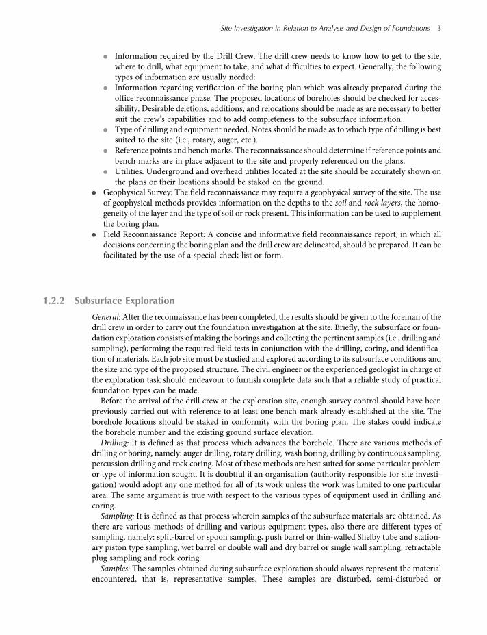
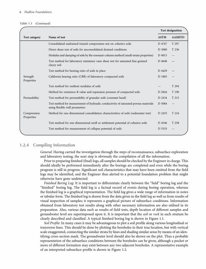