Section M.3 Lubrication - Toyota Textile Machinery
40
MARCH, 2010 Ver. 3.04 M.3 - 1 Section M.3 Lubrication M.3.1 Types of Lubricants and their Properties ........................... M.3-3 [ 1 ] Lubricant Types, Lubricating Points, and Quantity ... M.3-3 [ 2 ] Lubricant Symbols and the Corresponding Products Commercially Available ............................................ M.3-3 [ 3 ] Properties of Lubricants............................................ M.3-4 [ 4 ] Preparation and Lubricant Storage ........................... M.3-4 M.3.2 LUBE Electric Centralized Lubrication System (Optional) . M.3-6 [ 1 ] Outline ...................................................................... M.3-6 [ 2 ] Specifications of Lubrication Pump and Distributing Valves .................................................... M.3-6 [ 3 ] Precautions for Supplying and Storing Grease ........ M.3-8 [ 4 ] Troubleshooting ........................................................ M.3-9 M.3.3 Lubricating Method and Intervals ...................................... M.3-11 [ 1 ] Lubricating Method ................................................... M.3-11 [ 2 ] Lubrication Intervals and Lubricants ......................... M.3-13 [ 3 ] Oil Change................................................................ M.3-35
Transcript of Section M.3 Lubrication - Toyota Textile Machinery
Section M.3Lubrication
MARCH, 2010 Ver. 3.04
M.3.1 Types of Lubricants and their Properties ........................... M.3-3
[ 1 ] Lubricant Types, Lubricating Points, and Quantity ... M.3-3
[ 2 ] Lubricant Symbols and the Corresponding Products Commercially Available ............................................ M.3-3
[ 3 ] Properties of Lubricants............................................ M.3-4
[ 4 ] Preparation and Lubricant Storage........................... M.3-4
M.3.2 LUBE Electric Centralized Lubrication System (Optional) . M.3-6
[ 1 ] Outline ...................................................................... M.3-6
[ 2 ] Specifications of Lubrication Pump and Distributing Valves .................................................... M.3-6
[ 3 ] Precautions for Supplying and Storing Grease ........ M.3-8
[ 4 ] Troubleshooting........................................................ M.3-9
M.3.3 Lubricating Method and Intervals ...................................... M.3-11
[ 1 ] Lubricating Method................................................... M.3-11
[ 2 ] Lubrication Intervals and Lubricants......................... M.3-13
[ 3 ] Oil Change................................................................ M.3-35
M.3 - 1
M. MAINTENANCE • DISASSEMBLY/REASSEMBLY/ADJUSTMENT • LUBRICATION
M.3 Lubrication
Manual lubrication (Standard)
Manual lubrication is the standard for the LWT710. Use grease guns and oilers. Even with the electric centralizedlubrication system, manual lubrication is necessary in some places. The details are described in SubsectionM.3.3 [ 2 ] “Lubrication Intervals and Lubricants”.
Electric centralized lubrication system (Optional)
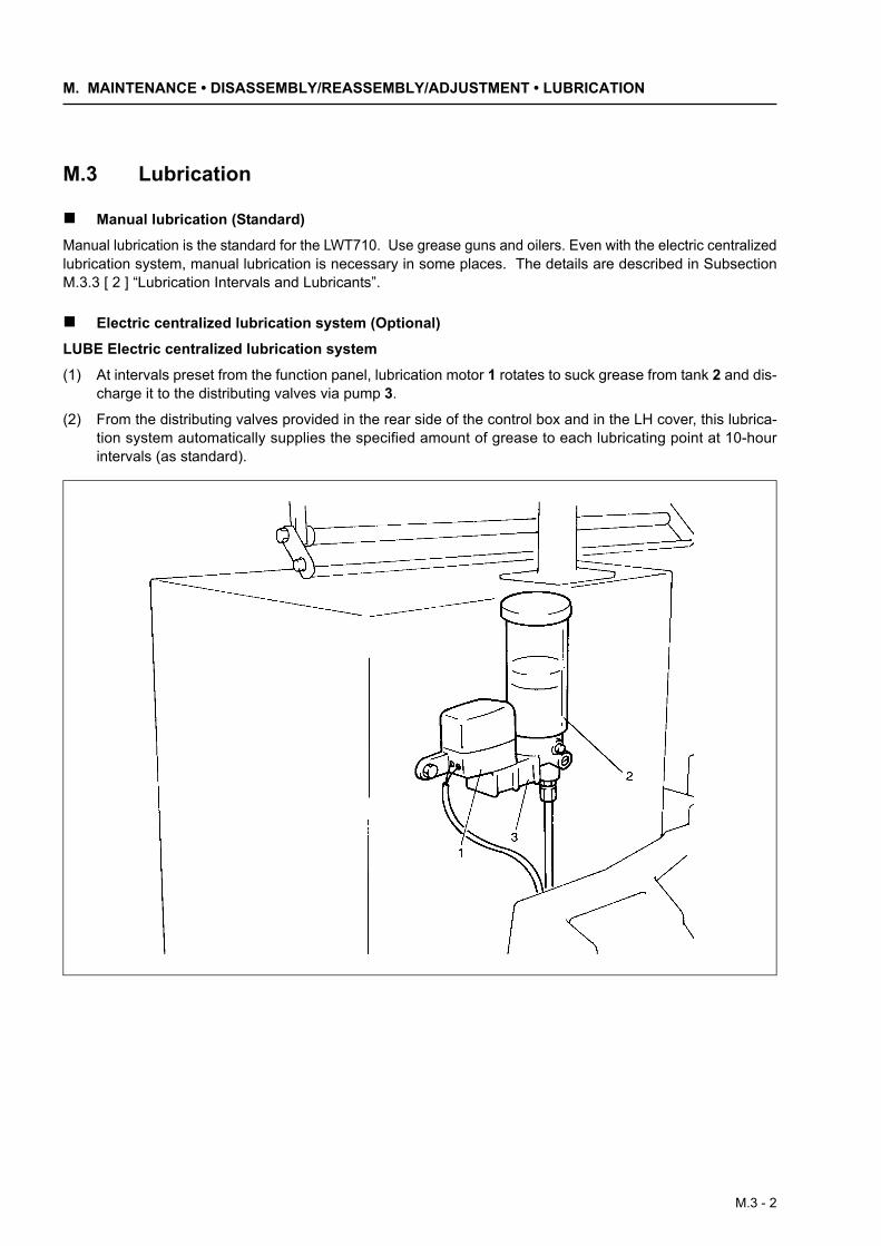
LUBE Electric centralized lubrication system
(1) At intervals preset from the function panel, lubrication motor 1 rotates to suck grease from tank 2 and dis-charge it to the distributing valves via pump 3.
(2) From the distributing valves provided in the rear side of the control box and in the LH cover, this lubrica-tion system automatically supplies the specified amount of grease to each lubricating point at 10-hourintervals (as standard).
M.3 - 2
M.3 Lubrication
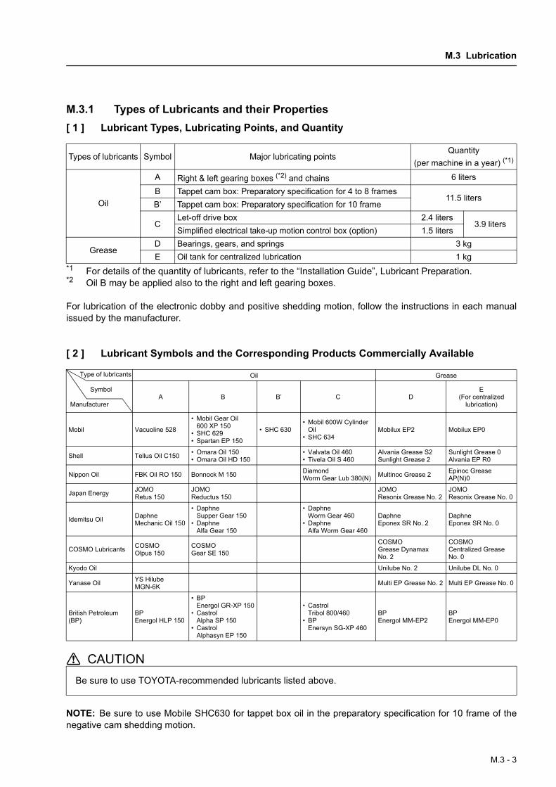
M.3.1 Types of Lubricants and their Properties[ 1 ] Lubricant Types, Lubricating Points, and Quantity
*1 For details of the quantity of lubricants, refer to the “Installation Guide”, Lubricant Preparation.*2 Oil B may be applied also to the right and left gearing boxes.
For lubrication of the electronic dobby and positive shedding motion, follow the instructions in each manualissued by the manufacturer.
[ 2 ] Lubricant Symbols and the Corresponding Products Commercially Available
NOTE: Be sure to use Mobile SHC630 for tappet box oil in the preparatory specification for 10 frame of thenegative cam shedding motion.
Types of lubricants Symbol Major lubricating pointsQuantity
(per machine in a year) (*1)
Oil
A Right & left gearing boxes (*2) and chains 6 liters
B Tappet cam box: Preparatory specification for 4 to 8 frames11.5 liters
B’ Tappet cam box: Preparatory specification for 10 frame
CLet-off drive box 2.4 liters
3.9 litersSimplified electrical take-up motion control box (option) 1.5 liters
GreaseD Bearings, gears, and springs 3 kgE Oil tank for centralized lubrication 1 kg
Oil Grease
A B B’ C DE
(For centralized lubrication)
Mobil Vacuoline 528
• Mobil Gear Oil 600 XP 150
• SHC 629• Spartan EP 150
• SHC 630• Mobil 600W Cylinder
Oil• SHC 634
Mobilux EP2 Mobilux EP0
Shell Tellus Oil C150 • Omara Oil 150• Omara Oil HD 150
• Valvata Oil 460• Tivela Oil S 460
Alvania Grease S2Sunlight Grease 2
Sunlight Grease 0Alvania EP R0
Nippon Oil FBK Oil RO 150 Bonnock M 150 Diamond Worm Gear Lub 380(N) Multinoc Grease 2 Epinoc Grease
AP(N)0
Japan Energy JOMO Retus 150
JOMO Reductus 150
JOMO Resonix Grease No. 2
JOMO Resonix Grease No. 0
Idemitsu Oil Daphne Mechanic Oil 150
• Daphne Supper Gear 150
• Daphne Alfa Gear 150
• Daphne Worm Gear 460
• Daphne Alfa Worm Gear 460
Daphne Eponex SR No. 2
Daphne Eponex SR No. 0
COSMO Lubricants COSMO Olpus 150
COSMO Gear SE 150
COSMO Grease Dynamax No. 2
COSMO Centralized Grease No. 0
Kyodo Oil Unilube No. 2 Unilube DL No. 0
Yanase Oil YS Hilube MGN-6K Multi EP Grease No. 2 Multi EP Grease No. 0
British Petroleum (BP)
BP Energol HLP 150
• BP Energol GR-XP 150
• Castrol Alpha SP 150
• Castrol Alphasyn EP 150
• Castrol Tribol 800/460
• BP Enersyn SG-XP 460
BP Energol MM-EP2
BP Energol MM-EP0
Be sure to use TOYOTA-recommended lubricants listed above.
Type of lubricants
Symbol
Manufacturer
M.3 - 3
M. MAINTENANCE • DISASSEMBLY/REASSEMBLY/ADJUSTMENT • LUBRICATION
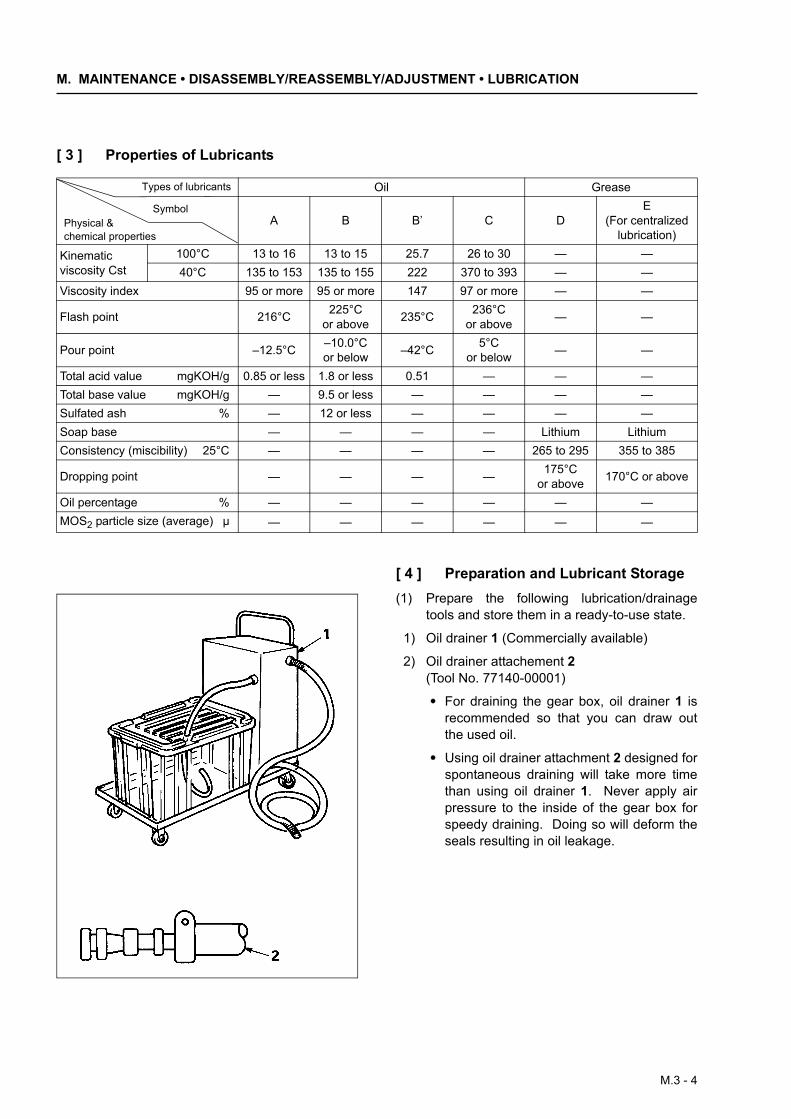
[ 3 ] Properties of Lubricants
[ 4 ] Preparation and Lubricant Storage(1) Prepare the following lubrication/drainage
tools and store them in a ready-to-use state.
1) Oil drainer 1 (Commercially available)
2) Oil drainer attachement 2 (Tool No. 77140-00001)
• For draining the gear box, oil drainer 1 isrecommended so that you can draw outthe used oil.
• Using oil drainer attachment 2 designed forspontaneous draining will take more timethan using oil drainer 1. Never apply airpressure to the inside of the gear box forspeedy draining. Doing so will deform theseals resulting in oil leakage.
Oil Grease
A B B’ C DE
(For centralized lubrication)
Kinematic viscosity Cst
100°C 13 to 16 13 to 15 25.7 26 to 30 — —40°C 135 to 153 135 to 155 222 370 to 393 — —
Viscosity index 95 or more 95 or more 147 97 or more — —
Flash point 216°C 225°C or above 235°C 236°C
or above — —
Pour point –12.5°C –10.0°C or below –42°C 5°C
or below — —
Total acid value mgKOH/g 0.85 or less 1.8 or less 0.51 — — —Total base value mgKOH/g — 9.5 or less — — — —Sulfated ash % — 12 or less — — — —Soap base — — — — Lithium LithiumConsistency (miscibility) 25°C — — — — 265 to 295 355 to 385
Dropping point — — — — 175°C or above 170°C or above
Oil percentage % — — — — — —MOS2 particle size (average) µ — — — — — —
Types of lubricants
SymbolPhysical & chemical properties
M.3 - 4
M.3 Lubrication
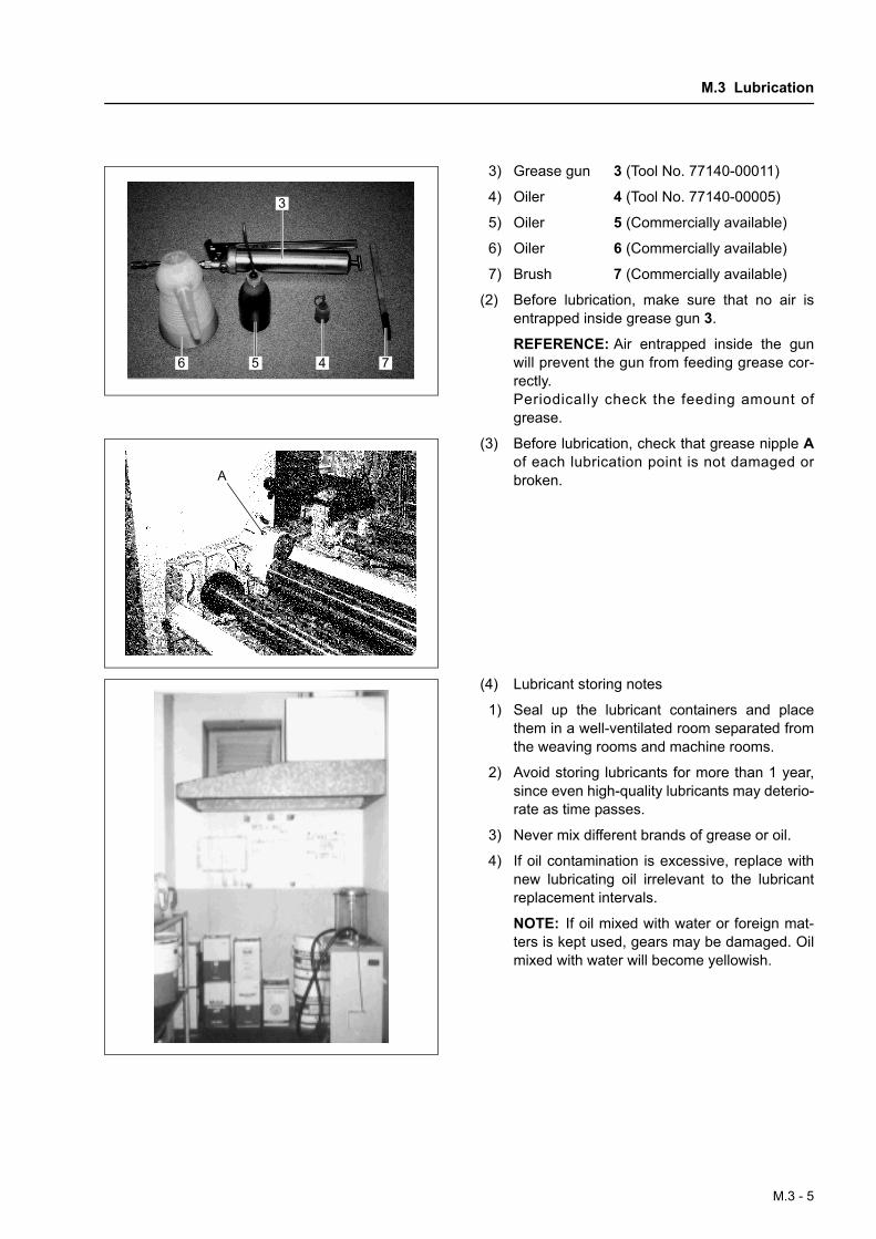
3) Grease gun 3 (Tool No. 77140-00011)
4) Oiler 4 (Tool No. 77140-00005)
5) Oiler 5 (Commercially available)
6) Oiler 6 (Commercially available)
7) Brush 7 (Commercially available)
(2) Before lubrication, make sure that no air isentrapped inside grease gun 3.
REFERENCE: Air entrapped inside the gunwill prevent the gun from feeding grease cor-rectly.Periodically check the feeding amount ofgrease.
(3) Before lubrication, check that grease nipple Aof each lubrication point is not damaged orbroken.
(4) Lubricant storing notes
1) Seal up the lubricant containers and placethem in a well-ventilated room separated fromthe weaving rooms and machine rooms.
2) Avoid storing lubricants for more than 1 year,since even high-quality lubricants may deterio-rate as time passes.
3) Never mix different brands of grease or oil.
4) If oil contamination is excessive, replace withnew lubricating oil irrelevant to the lubricantreplacement intervals.
NOTE: If oil mixed with water or foreign mat-ters is kept used, gears may be damaged. Oilmixed with water will become yellowish.
3
5 4 76
A
M.3 - 5
M. MAINTENANCE • DISASSEMBLY/REASSEMBLY/ADJUSTMENT • LUBRICATION
M.3.2 LUBE Electric Centralized Lubrication System (Optional)
[ 1 ] OutlineThis system is composed of a motor-driven pump(GMS-20-80-TS-4L), piston valves (MG) and pres-sure switch. The pump pressurizes grease to feedit into the pipes. As the in-pipe pressure increases,the piston in each connected valve moves inwardsso as to supply the specified amount of grease tothe lubrication point. The pressure switch detectsthe in-pipe pressure change, signaling the CPU tooptimize the pump.When the pump stops pressurizing grease, the in-pipe pressure automatically decreases so that thepiston moves back to the retracted position. Thisretracting stroke of the piston will take in grease(which will be supplied at the next discharge strokeof the piston) into the valve.The above operation could easily receive a seriousinfluence by dust, fly, and air bubbles if coming intogrease. Those foreign materials will cause pump orvalve problems; in the worst case, they will result ina damaged weaving machine. Always observe theprecautions given in item [ 3 ].
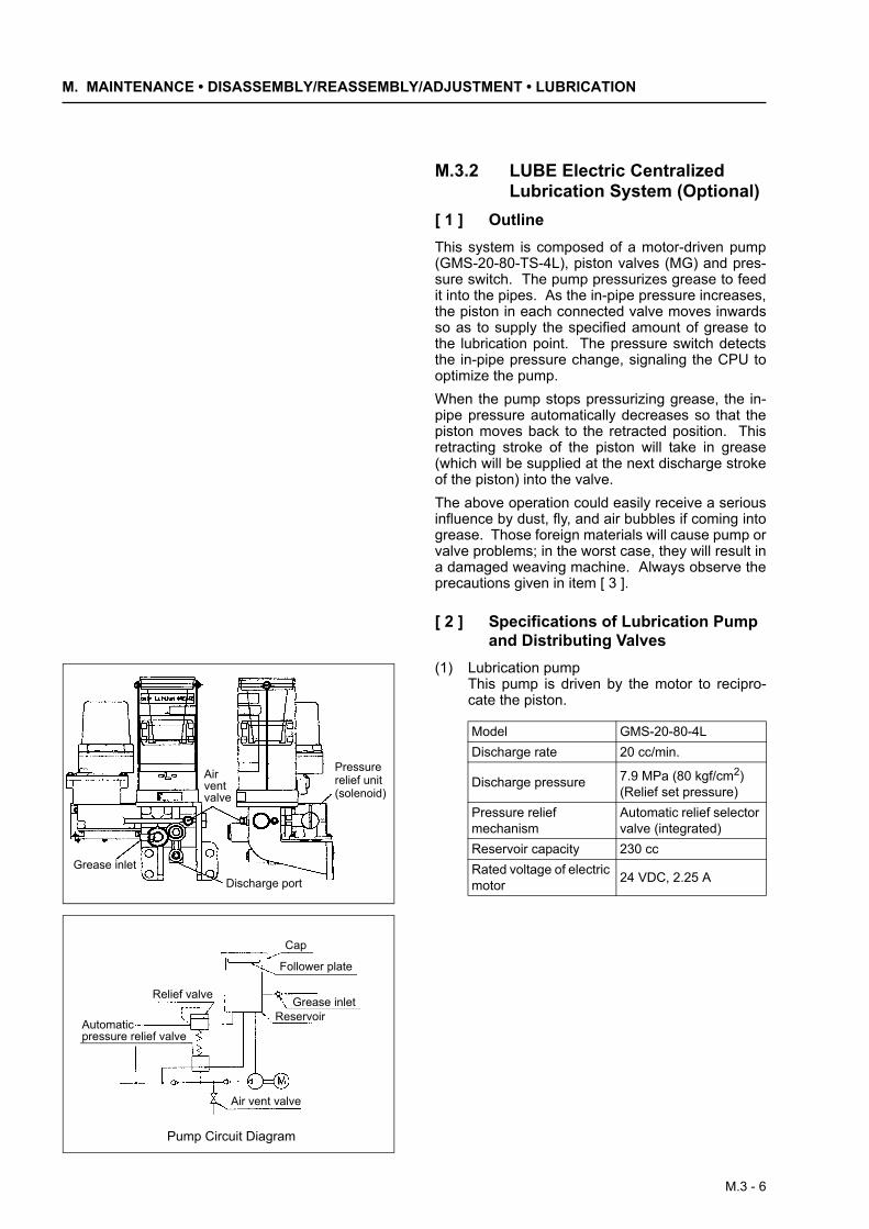
[ 2 ] Specifications of Lubrication Pump and Distributing Valves
(1) Lubrication pumpThis pump is driven by the motor to recipro-cate the piston.
Air vent valve
Grease inletDischarge port
Pressure relief unit (solenoid)
Cap
Follower plate
Grease inletReservoir
Air vent valve
Relief valve
Pump Circuit Diagram
Automaticpressure relief valve
Model GMS-20-80-4LDischarge rate 20 cc/min.
Discharge pressure 7.9 MPa (80 kgf/cm2)(Relief set pressure)
Pressure relief mechanism
Automatic relief selector valve (integrated)
Reservoir capacity 230 ccRated voltage of electric motor 24 VDC, 2.25 A
M.3 - 6
M.3 Lubrication
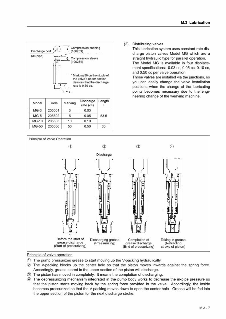
(2) Distributing valvesThis lubrication system uses constant-rate dis-charge piston valves Model MG which are astraight hydraulic type for parallel operation.The Model MG is available in four displace-ment specifications: 0.03 cc, 0.05 cc, 0.10 cc,and 0.50 cc per valve operation.Those valves are installed via the junctions, soyou can easily change the valve installationpositions when the change of the lubricatingpoints becomes necessary due to the engi-neering change of the weaving machine.
Principle of valve operationThe pump pressurizes grease to start moving up the V-packing hydraulically.The V-packing blocks up the center hole so that the piston moves inwards against the spring force.Accordingly, grease stored in the upper section of the piston will discharge.The piston has moved in completely. It means the completion of discharging.The depressurizing mechanism integrated in the pump body works to decrease the in-pipe pressure sothat the piston starts moving back by the spring force provided in the valve. Accordingly, the insidebecomes pressurized so that the V-packing moves down to open the center hole. Grease will be fed intothe upper section of the piston for the next discharge stroke.
Discharge port(ø4 pipe)
Compression bushing(106253)
Compression sleeve(106254)
* Marking 50 on the nipple of the valve’s upper section denotes that the discharge rate is 0.50 cc.
Model Code Marking Discharge rate (cc)
Length L
MG-3 205501 3 0.0353.5MG-5 205502 5 0.05
MG-10 205503 10 0.10MG-50 205506 50 0.50 65
Principle of Valve Operation
↑Discharge
↑Before the start of grease discharge
(Start of pressurizing)
Completion of grease discharge
(End of pressurizing)
Taking in grease (Retracting
stroke of piston)
Discharging grease (Pressurizing)
M.3 - 7
M. MAINTENANCE • DISASSEMBLY/REASSEMBLY/ADJUSTMENT • LUBRICATION
[ 3 ] Precautions for Supplying and Storing Grease
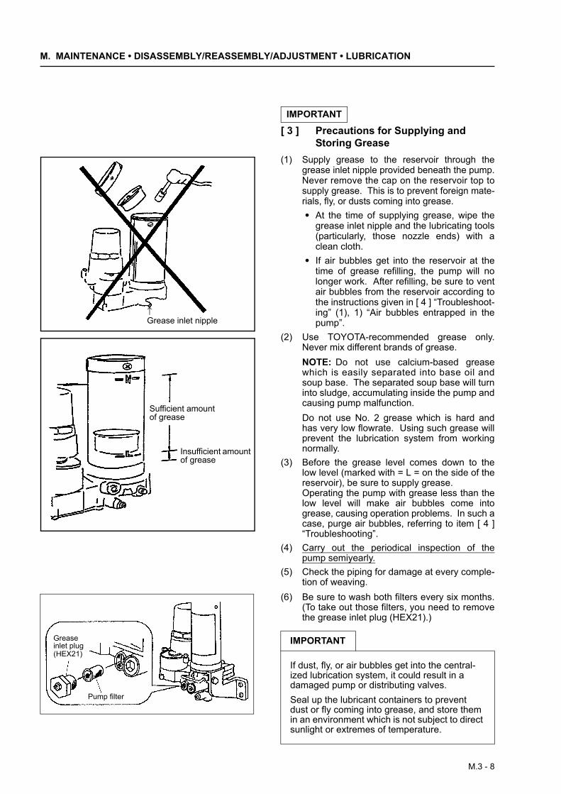
(1) Supply grease to the reservoir through thegrease inlet nipple provided beneath the pump.Never remove the cap on the reservoir top tosupply grease. This is to prevent foreign mate-rials, fly, or dusts coming into grease.• At the time of supplying grease, wipe the
grease inlet nipple and the lubricating tools(particularly, those nozzle ends) with aclean cloth.
• If air bubbles get into the reservoir at thetime of grease refilling, the pump will nolonger work. After refilling, be sure to ventair bubbles from the reservoir according tothe instructions given in [ 4 ] “Troubleshoot-ing” (1), 1) “Air bubbles entrapped in thepump”.
(2) Use TOYOTA-recommended grease only.Never mix different brands of grease.NOTE: Do not use calcium-based greasewhich is easily separated into base oil andsoup base. The separated soup base will turninto sludge, accumulating inside the pump andcausing pump malfunction.Do not use No. 2 grease which is hard andhas very low flowrate. Using such grease willprevent the lubrication system from workingnormally.
(3) Before the grease level comes down to thelow level (marked with = L = on the side of thereservoir), be sure to supply grease.Operating the pump with grease less than thelow level will make air bubbles come intogrease, causing operation problems. In such acase, purge air bubbles, referring to item [ 4 ]“Troubleshooting”.
(4) Carry out the periodical inspection of thepump semiyearly.
(5) Check the piping for damage at every comple-tion of weaving.
(6) Be sure to wash both filters every six months.(To take out those filters, you need to removethe grease inlet plug (HEX21).)
IMPORTANT
↑Grease inlet nipple
Sufficient amount of grease
Insufficient amount of grease
Pump filter
Grease inlet plug(HEX21)
IMPORTANT
If dust, fly, or air bubbles get into the central-ized lubrication system, it could result in a damaged pump or distributing valves.Seal up the lubricant containers to prevent dust or fly coming into grease, and store them in an environment which is not subject to direct sunlight or extremes of temperature.
M.3 - 8
M.3 Lubrication
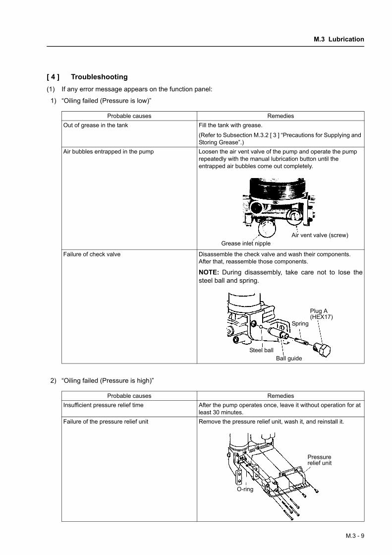
[ 4 ] Troubleshooting(1) If any error message appears on the function panel:
1) “Oiling failed (Pressure is low)”
2) “Oiling failed (Pressure is high)”
Probable causes RemediesOut of grease in the tank Fill the tank with grease.
(Refer to Subsection M.3.2 [ 3 ] “Precautions for Supplying and Storing Grease”.)
Air bubbles entrapped in the pump Loosen the air vent valve of the pump and operate the pump repeatedly with the manual lubrication button until the entrapped air bubbles come out completely.
Failure of check valve Disassemble the check valve and wash their components. After that, reassemble those components.
NOTE: During disassembly, take care not to lose thesteel ball and spring.
Probable causes RemediesInsufficient pressure relief time After the pump operates once, leave it without operation for at
least 30 minutes.Failure of the pressure relief unit Remove the pressure relief unit, wash it, and reinstall it.
Grease inlet nippleAir vent valve (screw)
Plug A(HEX17)
Spring
Ball guideSteel ball
O-ring
Pressure relief unit
M.3 - 9
M. MAINTENANCE • DISASSEMBLY/REASSEMBLY/ADJUSTMENT • LUBRICATION
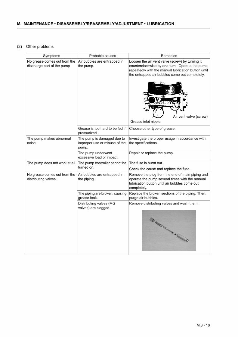
(2) Other problems
Symptoms Probable causes RemediesNo grease comes out from the discharge port of the pump
Air bubbles are entrapped in the pump.
Loosen the air vent valve (screw) by turning it counterclockwise by one turn. Operate the pump repeatedly with the manual lubrication button until the entrapped air bubbles come out completely.
Grease is too hard to be fed if pressurized.
Choose other type of grease.
The pump makes abnormal noise.
The pump is damaged due to improper use or misuse of the pump.
Investigate the proper usage in accordance with the specifications.
The pump underwent excessive load or impact.
Repair or replace the pump.
The pump does not work at all. The pump controller cannot be turned on.
The fuse is burnt out.
Check the cause and replace the fuse.No grease comes out from the distributing valves.
Air bubbles are entrapped in the piping.
Remove the plug from the end of main piping and operate the pump several times with the manual lubrication button until air bubbles come out completely.
The piping are broken, causing grease leak.
Replace the broken sections of the piping. Then, purge air bubbles.
Distributing valves (MG valves) are clogged.
Remove distributing valves and wash them.
Grease inlet nippleAir vent valve (screw)
M.3 - 10
M.3 Lubrication
M.3.3 Lubricating Method and Intervals
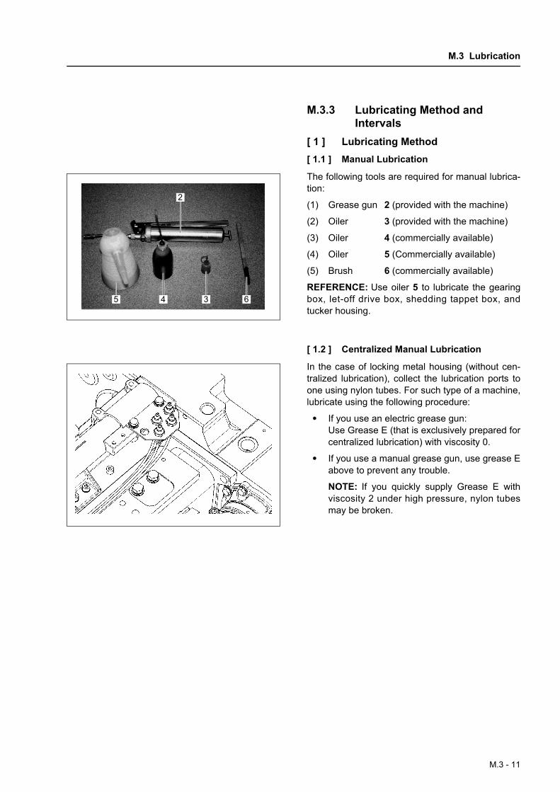
[ 1 ] Lubricating Method[ 1.1 ] Manual Lubrication
The following tools are required for manual lubrica-tion:
(1) Grease gun 2 (provided with the machine)
(2) Oiler 3 (provided with the machine)
(3) Oiler 4 (commercially available)
(4) Oiler 5 (Commercially available)
(5) Brush 6 (commercially available)
REFERENCE: Use oiler 5 to lubricate the gearingbox, let-off drive box, shedding tappet box, andtucker housing.
[ 1.2 ] Centralized Manual Lubrication
In the case of locking metal housing (without cen-tralized lubrication), collect the lubrication ports toone using nylon tubes. For such type of a machine,lubricate using the following procedure:
• If you use an electric grease gun:Use Grease E (that is exclusively prepared forcentralized lubrication) with viscosity 0.
• If you use a manual grease gun, use grease Eabove to prevent any trouble.
NOTE: If you quickly supply Grease E withviscosity 2 under high pressure, nylon tubesmay be broken.
2
4 3 65
M.3 - 11
M. MAINTENANCE • DISASSEMBLY/REASSEMBLY/ADJUSTMENT • LUBRICATION
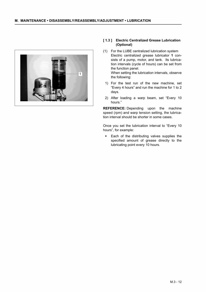
[ 1.3 ] Electric Centralized Grease Lubrication (Optional)
(1) For the LUBE centralized lubrication systemElectric centralized grease lubricator 1 con-sists of a pump, motor, and tank. Its lubrica-tion intervals (cycle of hours) can be set fromthe function panel.When setting the lubrication intervals, observethe following:
1) For the test run of the new machine, set“Every 4 hours” and run the machine for 1 to 2days.
2) After loading a warp beam, set “Every 10hours.”
REFERENCE: Depending upon the machinespeed (rpm) and warp tension setting, the lubrica-tion interval should be shorter in some cases.
Once you set the lubrication interval to “Every 10hours”, for example:
• Each of the distributing valves supplies thespecified amount of grease directly to thelubricating point every 10 hours.
1
M.3 - 12

M.3 Lubrication
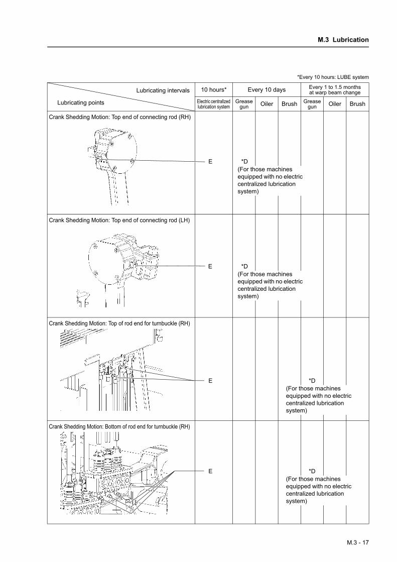
[ 2 ] Lubrication Intervals and LubricantsPiping may be omitted for (E) depending on the specification. Generally use a grease gun for lubrication. *Every 10 hours: LUBE system
10 hours* Every 10 days Every 1 to 1.5 months at warp beam change
Electric centrallzed lubrication system
Grease gun Oiler Brush Grease
gun Oiler Brush
Tappet Cam Shedding Motion: Jack lever shaft (RH, front)
Tappet Cam Shedding Motion: Jack lever shaft (RH, rear)
Tappet Cam Shedding Motion: Jack lever shaft (LH, front)
Tappet Cam Shedding Motion: Jack lever shaft (LH, rear)
Lubricating intervals
Lubricating points
(E) *D(For those machines equipped with no electric centralized lubrication system)
(E) *D(For those machines equipped with no electric centralized lubrication system)
(E) *D(For those machines equipped with no electric centralized lubrication system)
(E) *D(For those machines equipped with no electric centralized lubrication system)
M.3 - 13
M. MAINTENANCE • DISASSEMBLY/REASSEMBLY/ADJUSTMENT • LUBRICATION
*Every 10 hours: LUBE system
10 hours* Every 10 days Every 1 to 1.5 months at warp beam change
Electric centrallzed lubrication system
Grease gun Oiler Brush Grease
gun Oiler Brush
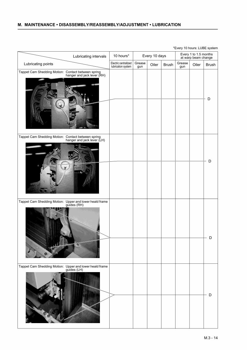
Tappet Cam Shedding Motion: Contact between spring hanger and jack lever (RH)
Tappet Cam Shedding Motion: Contact between spring hanger and jack lever (LH)
Tappet Cam Shedding Motion: Upper and lower heald frame guides (RH)
Tappet Cam Shedding Motion: Upper and lower heald frame guides (LH)
Lubricating intervals
Lubricating points
D
D
D
D
M.3 - 14
M.3 Lubrication
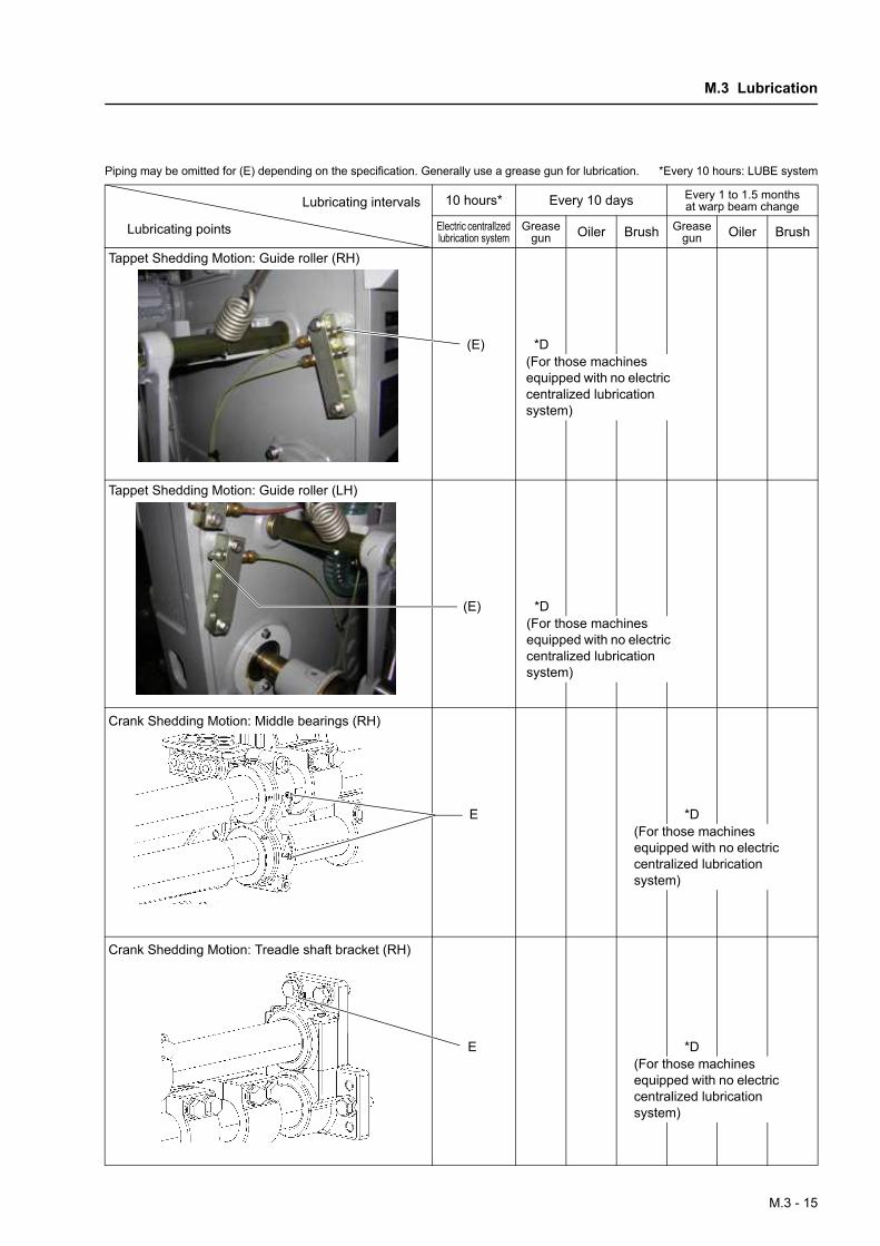
Piping may be omitted for (E) depending on the specification. Generally use a grease gun for lubrication. *Every 10 hours: LUBE system
10 hours* Every 10 days Every 1 to 1.5 months at warp beam change
Electric centrallzed lubrication system
Grease gun Oiler Brush Grease
gun Oiler Brush
Tappet Shedding Motion: Guide roller (RH)
Tappet Shedding Motion: Guide roller (LH)
Crank Shedding Motion: Middle bearings (RH)
Crank Shedding Motion: Treadle shaft bracket (RH)
Lubricating intervals
Lubricating points
(E) *D(For those machines equipped with no electric centralized lubrication system)
(E) *D(For those machines equipped with no electric centralized lubrication system)
E *D(For those machines equipped with no electric centralized lubrication system)
E *D(For those machines equipped with no electric centralized lubrication system)
M.3 - 15

M. MAINTENANCE • DISASSEMBLY/REASSEMBLY/ADJUSTMENT • LUBRICATION
*Every 10 hours: LUBE system
10 hours* Every 10 days Every 1 to 1.5 months at warp beam change
Electric centrallzed lubrication system
Grease gun Oiler Brush Grease
gun Oiler Brush
Crank Shedding Motion: Middle bearings (LH)
Crank Shedding Motion: Treadle shaft bracket (LH)
Crank Shedding Motion: Bottom end of connecting rod (RH)
Crank Shedding Motion: Bottom end of connecting rod (LH)
Lubricating intervals
Lubricating points
E *D(For those machines equipped with no electric centralized lubrication system)
E *D(For those machines equipped with no electric centralized lubrication system)
E *D(For those machines equipped with no electric centralized lubrication system)
E *D(For those machines equipped with no electric centralized lubrication system)
M.3 - 16
M.3 Lubrication
*Every 10 hours: LUBE system
10 hours* Every 10 days Every 1 to 1.5 months at warp beam change
Electric centrallzed lubrication system
Grease gun Oiler Brush Grease
gun Oiler Brush
Crank Shedding Motion: Top end of connecting rod (RH)
Crank Shedding Motion: Top end of connecting rod (LH)
Crank Shedding Motion: Top of rod end for turnbuckle (RH)
Crank Shedding Motion: Bottom of rod end for turnbuckle (RH)
Lubricating intervals
Lubricating points
E *D(For those machines equipped with no electric centralized lubrication system)
E *D(For those machines equipped with no electric centralized lubrication system)
E *D(For those machines equipped with no electric centralized lubrication system)
E *D(For those machines equipped with no electric centralized lubrication system)
M.3 - 17
M. MAINTENANCE • DISASSEMBLY/REASSEMBLY/ADJUSTMENT • LUBRICATION
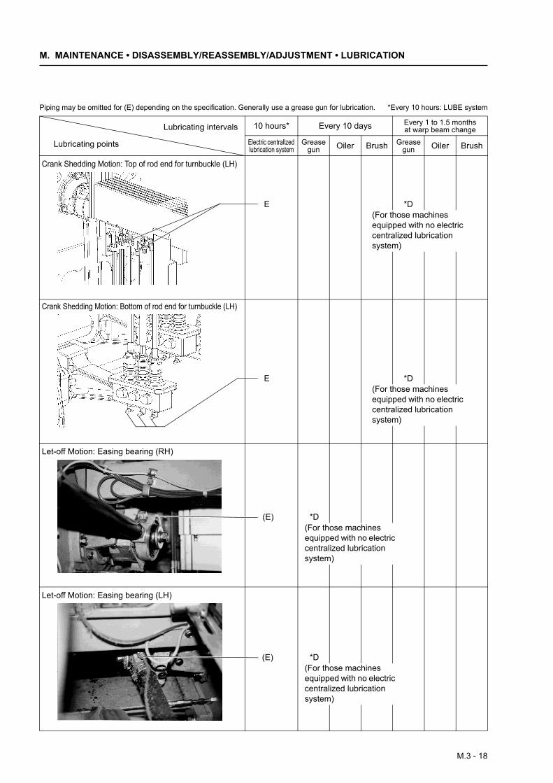
Piping may be omitted for (E) depending on the specification. Generally use a grease gun for lubrication. *Every 10 hours: LUBE system
10 hours* Every 10 days Every 1 to 1.5 months at warp beam change
Electric centrallzed lubrication system
Grease gun Oiler Brush Grease
gun Oiler Brush
Crank Shedding Motion: Top of rod end for turnbuckle (LH)
Crank Shedding Motion: Bottom of rod end for turnbuckle (LH)
Let-off Motion: Easing bearing (RH)
Let-off Motion: Easing bearing (LH)
Lubricating intervals
Lubricating points
E *D(For those machines equipped with no electric centralized lubrication system)
E *D(For those machines equipped with no electric centralized lubrication system)
(E) *D(For those machines equipped with no electric centralized lubrication system)
(E) *D(For those machines equipped with no electric centralized lubrication system)
M.3 - 18
M.3 Lubrication
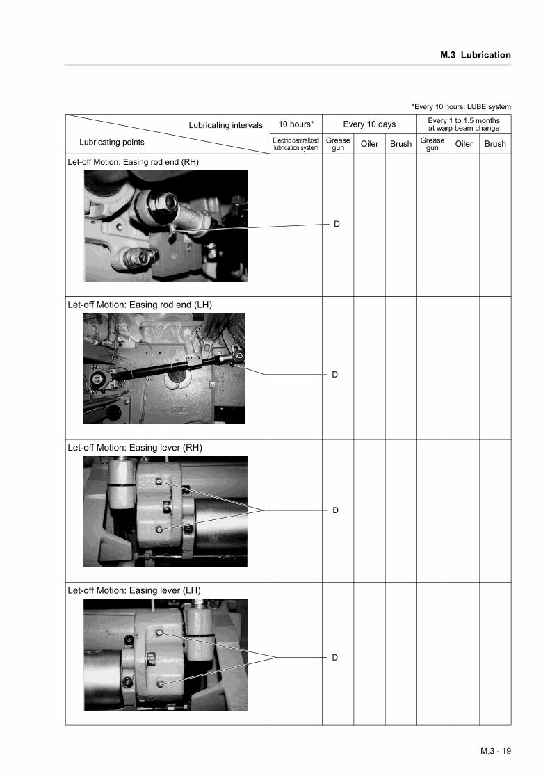
*Every 10 hours: LUBE system
10 hours* Every 10 days Every 1 to 1.5 months at warp beam change
Electric centrallzed lubrication system
Grease gun Oiler Brush Grease
gun Oiler Brush
Let-off Motion: Easing rod end (RH)
Let-off Motion: Easing rod end (LH)
Let-off Motion: Easing lever (RH)
Let-off Motion: Easing lever (LH)
Lubricating intervals
Lubricating points
D
D
D
D
M.3 - 19
M. MAINTENANCE • DISASSEMBLY/REASSEMBLY/ADJUSTMENT • LUBRICATION
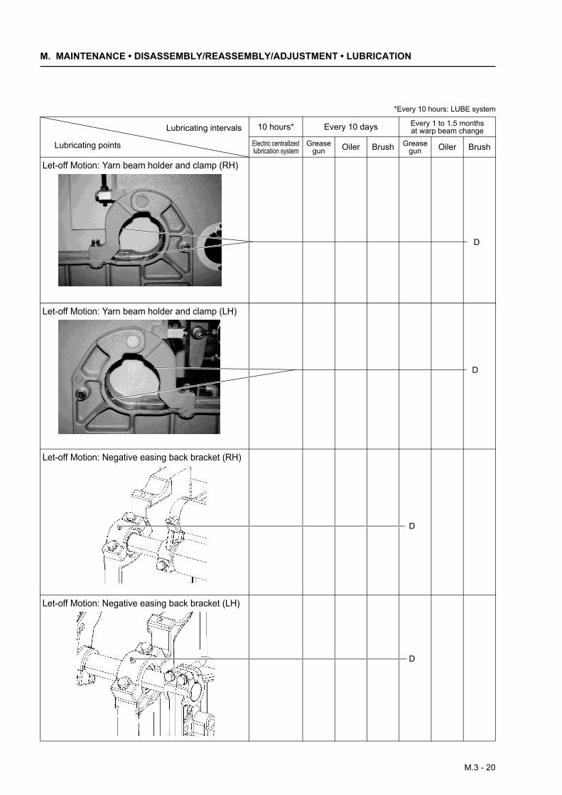
*Every 10 hours: LUBE system
10 hours* Every 10 days Every 1 to 1.5 months at warp beam change
Electric centrallzed lubrication system
Grease gun Oiler Brush Grease
gun Oiler Brush
Let-off Motion: Yarn beam holder and clamp (RH)
Let-off Motion: Yarn beam holder and clamp (LH)
Let-off Motion: Negative easing back bracket (RH)
Let-off Motion: Negative easing back bracket (LH)
Lubricating intervals
Lubricating points
D
D
D
D
M.3 - 20
M.3 Lubrication
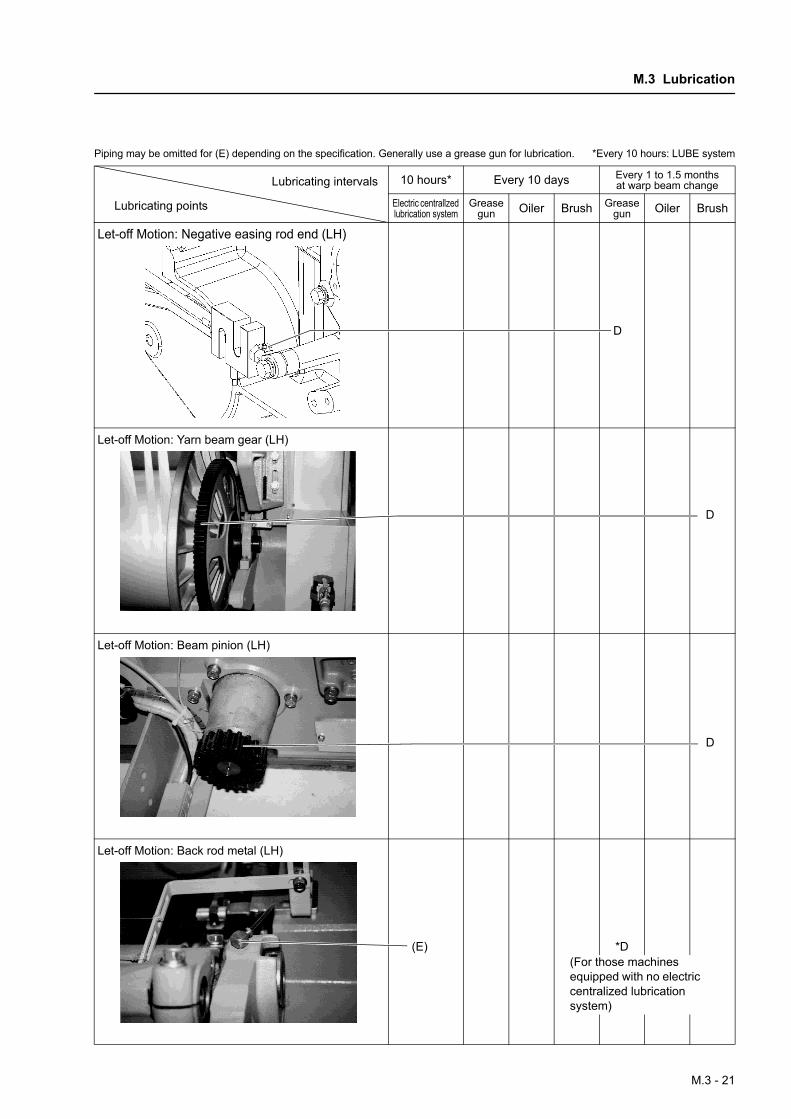
Piping may be omitted for (E) depending on the specification. Generally use a grease gun for lubrication. *Every 10 hours: LUBE system
10 hours* Every 10 days Every 1 to 1.5 months at warp beam change
Electric centrallzed lubrication system
Grease gun Oiler Brush Grease
gun Oiler Brush
Let-off Motion: Negative easing rod end (LH)
Let-off Motion: Yarn beam gear (LH)
Let-off Motion: Beam pinion (LH)
Let-off Motion: Back rod metal (LH)
Lubricating intervals
Lubricating points
D
D
D
(E) *D(For those machines equipped with no electric centralized lubrication system)
M.3 - 21
M. MAINTENANCE • DISASSEMBLY/REASSEMBLY/ADJUSTMENT • LUBRICATION
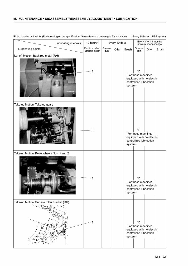
Piping may be omitted for (E) depending on the specification. Generally use a grease gun for lubrication. *Every 10 hours: LUBE system
10 hours* Every 10 days Every 1 to 1.5 months at warp beam change
Electric centrallzed lubrication system
Grease gun Oiler Brush Grease
gun Oiler Brush
Let-off Motion: Back rod metal (RH)
Take-up Motion: Take-up gears
Take-up Motion: Bevel wheels Nos. 1 and 2
Take-up Motion: Surface roller bracket (RH)
Lubricating intervals
Lubricating points
(E) *D(For those machines equipped with no electric centralized lubrication system)
(E) *D(For those machines equipped with no electric centralized lubrication system)
(E) *D(For those machines equipped with no electric centralized lubrication system)
(E) *D(For those machines equipped with no electric centralized lubrication system)
M.3 - 22
M.3 Lubrication
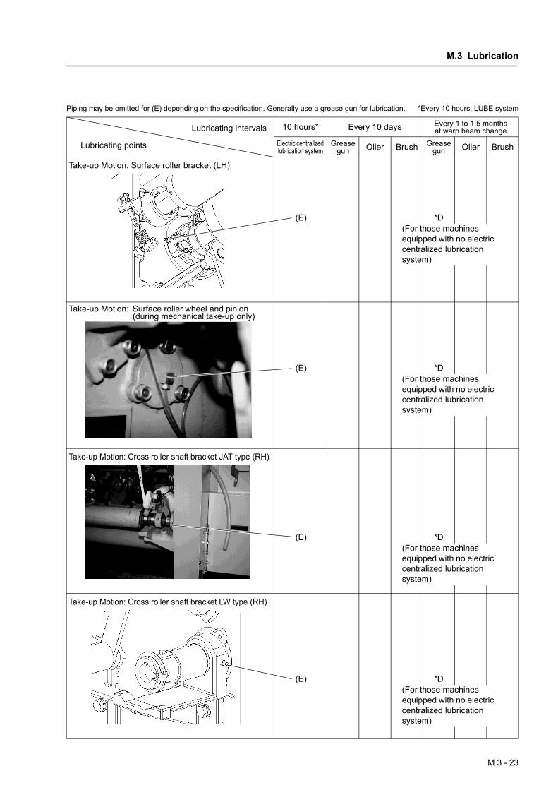
Piping may be omitted for (E) depending on the specification. Generally use a grease gun for lubrication. *Every 10 hours: LUBE system
10 hours* Every 10 days Every 1 to 1.5 months at warp beam change
Electric centrallzed lubrication system
Grease gun Oiler Brush Grease
gun Oiler Brush
Take-up Motion: Surface roller bracket (LH)
Take-up Motion: Surface roller wheel and pinion(during mechanical take-up only)
Take-up Motion: Cross roller shaft bracket JAT type (RH)
Take-up Motion: Cross roller shaft bracket LW type (RH)
Lubricating intervals
Lubricating points
(E) *D(For those machines equipped with no electric centralized lubrication system)
(E) *D(For those machines equipped with no electric centralized lubrication system)
(E) *D(For those machines equipped with no electric centralized lubrication system)
(E) *D(For those machines equipped with no electric centralized lubrication system)
M.3 - 23
M. MAINTENANCE • DISASSEMBLY/REASSEMBLY/ADJUSTMENT • LUBRICATION
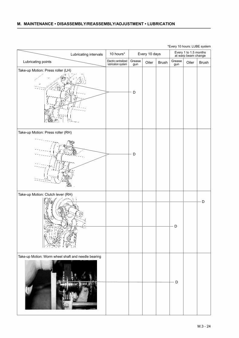
*Every 10 hours: LUBE system
10 hours* Every 10 days Every 1 to 1.5 months at warp beam change
Electric centrallzed lubrication system
Grease gun Oiler Brush Grease
gun Oiler Brush
Take-up Motion: Press roller (LH)
Take-up Motion: Press roller (RH)
Take-up Motion: Clutch lever (RH)
Take-up Motion: Worm wheel shaft and needle bearing
Lubricating intervals
Lubricating points
D
D
D
D
D
M.3 - 24
M.3 Lubrication
*Every 10 hours: LUBE system
10 hours* Every 10 days Every 1 to 1.5 months at warp beam change
Electric centrallzed lubrication system
Grease gun Oiler Brush Grease
gun Oiler Brush
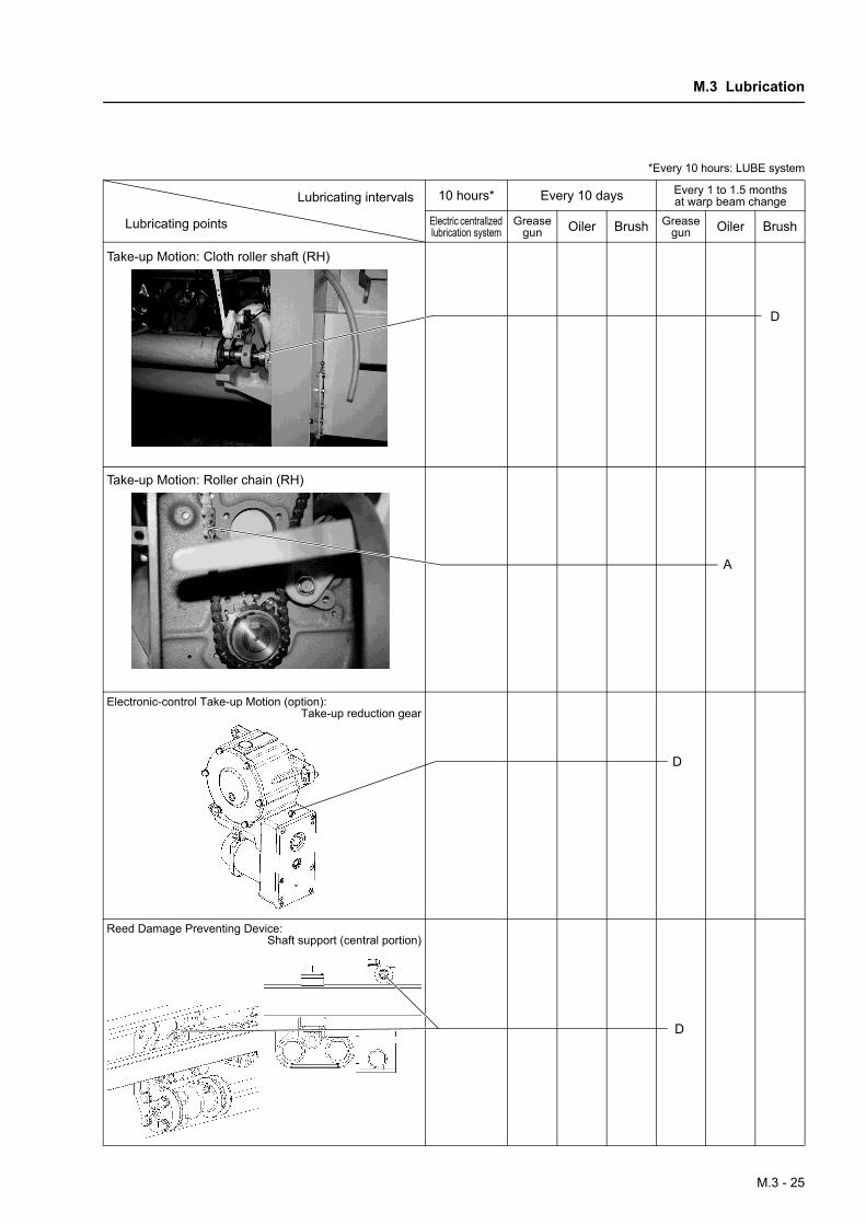
Take-up Motion: Cloth roller shaft (RH)
Take-up Motion: Roller chain (RH)
Electronic-control Take-up Motion (option): Take-up reduction gear
Reed Damage Preventing Device: Shaft support (central portion)
Lubricating intervals
Lubricating points
D
A
D
D
M.3 - 25
M. MAINTENANCE • DISASSEMBLY/REASSEMBLY/ADJUSTMENT • LUBRICATION
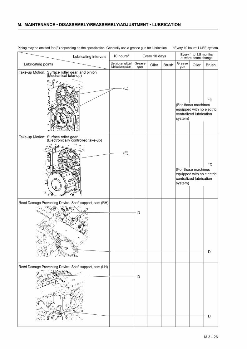
Piping may be omitted for (E) depending on the specification. Generally use a grease gun for lubrication. *Every 10 hours: LUBE system
10 hours* Every 10 days Every 1 to 1.5 months at warp beam change
Electric centrallzed lubrication system
Grease gun Oiler Brush Grease
gun Oiler Brush
Take-up Motion: Surface roller gear, and pinion (Mechanical take-up)
Take-up Motion: Surface roller gear (Electronically controlled take-up)
Reed Damage Preventing Device: Shaft support, cam (RH)
Reed Damage Preventing Device: Shaft support, cam (LH)
Lubricating intervals
Lubricating points
(E)
*D(For those machines equipped with no electric centralized lubrication system)
*D(For those machines equipped with no electric centralized lubrication system)
(E)
D
D
D
D
M.3 - 26
M.3 Lubrication
*Every 10 hours: LUBE system
10 hours* Every 10 days Every 1 to 1.5 months at warp beam change
Electric centrallzed lubrication system
Grease gun Oiler Brush Grease
gun Oiler Brush
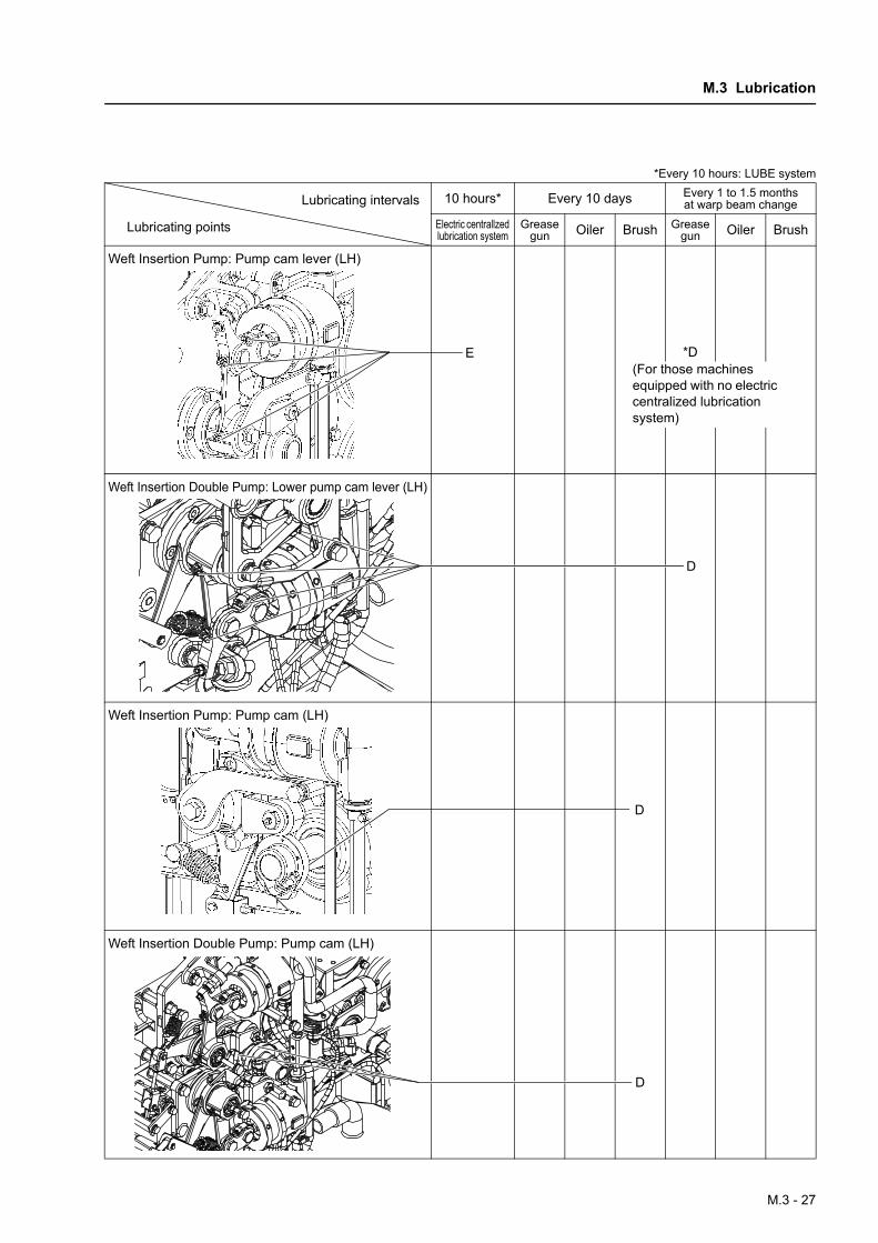
Weft Insertion Pump: Pump cam lever (LH)
Weft Insertion Double Pump: Lower pump cam lever (LH)
Weft Insertion Pump: Pump cam (LH)
Weft Insertion Double Pump: Pump cam (LH)
Lubricating intervals
Lubricating points
*D(For those machines equipped with no electric centralized lubrication system)
E
D
D
D
M.3 - 27
M. MAINTENANCE • DISASSEMBLY/REASSEMBLY/ADJUSTMENT • LUBRICATION
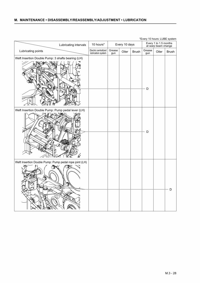
Weft Insertion Double Pump: 3 shafts bearing (LH)
Weft Insertion Double Pump: Pump pedal lever (LH)
Weft Insertion Double Pump: Pump pedal rope joint (LH)
*Every 10 hours: LUBE system
10 hours* Every 10 days Every 1 to 1.5 months at warp beam change
Electric centrallzed lubrication system
Grease gun Oiler Brush Grease
gun Oiler Brush
Lubricating intervals
Lubricating points
D
D
D
M.3 - 28
M.3 Lubrication
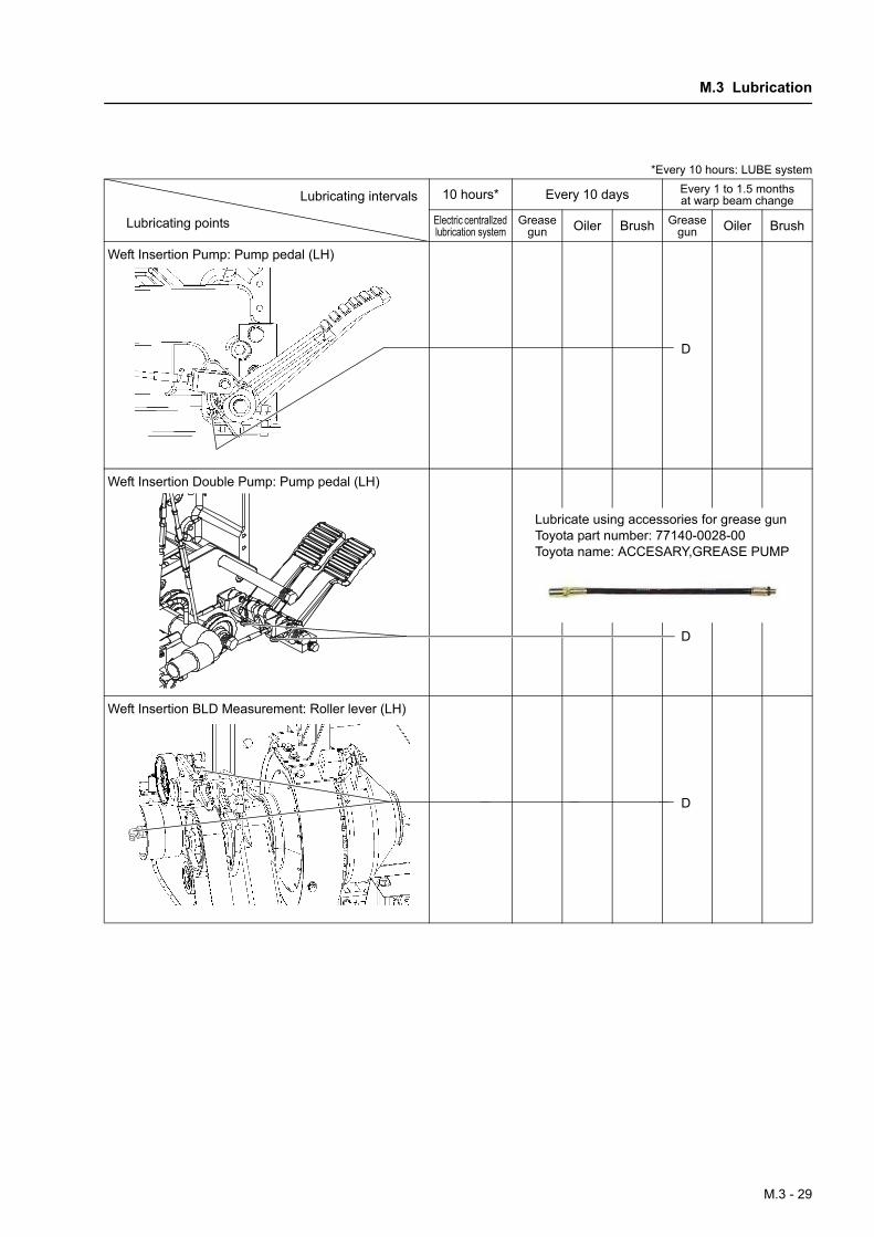
Weft Insertion Pump: Pump pedal (LH)
Weft Insertion Double Pump: Pump pedal (LH)
Weft Insertion BLD Measurement: Roller lever (LH)
*Every 10 hours: LUBE system
10 hours* Every 10 days Every 1 to 1.5 months at warp beam change
Electric centrallzed lubrication system
Grease gun Oiler Brush Grease
gun Oiler Brush
Lubricating intervals
Lubricating points
D
D
Lubricate using accessories for grease gunToyota part number: 77140-0028-00Toyota name: ACCESARY,GREASE PUMP
D
M.3 - 29
M. MAINTENANCE • DISASSEMBLY/REASSEMBLY/ADJUSTMENT • LUBRICATION
*Every 10 hours: LUBE system
10 hours* Every 10 days Every 1 to 1.5 months at warp beam change
Electric centrallzed lubrication system
Grease gun Oiler Brush Grease
gun Oiler Brush
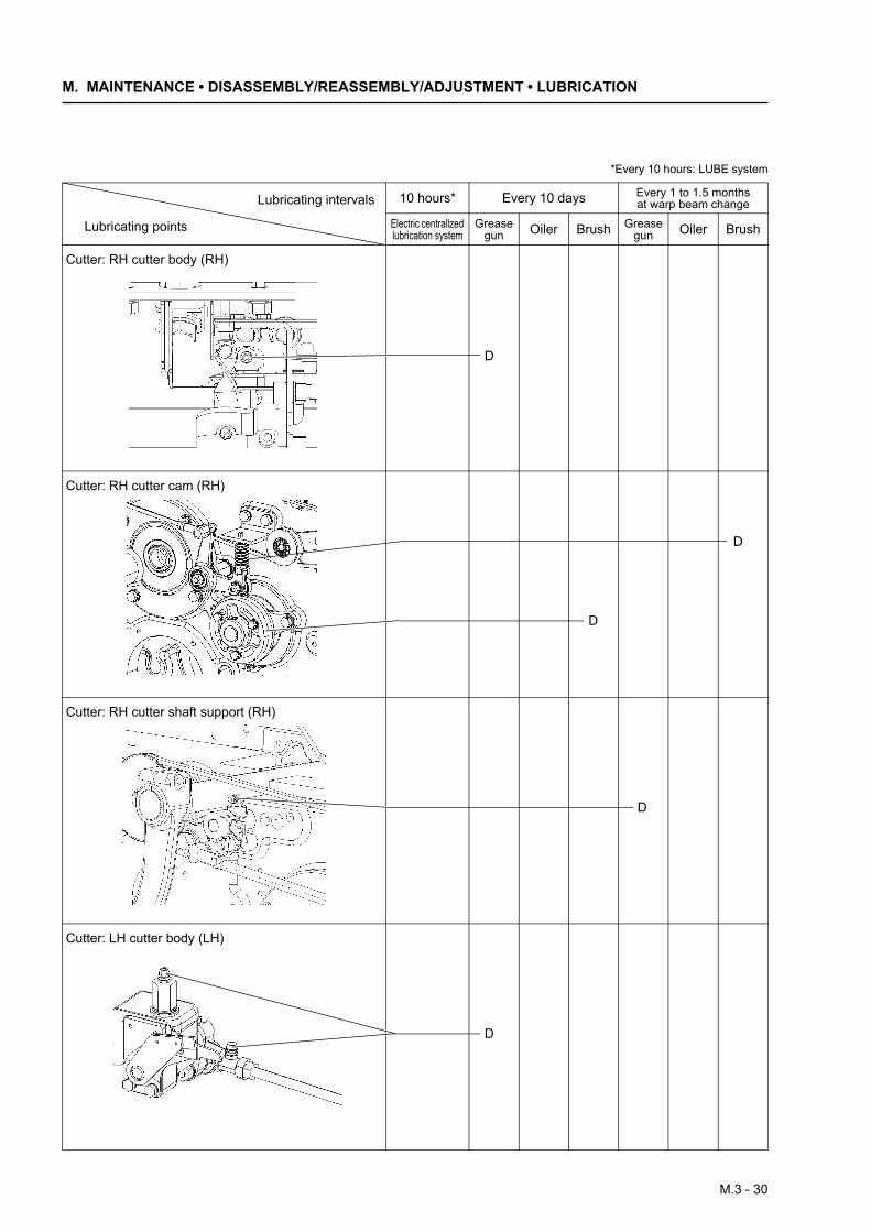
Cutter: RH cutter body (RH)
Cutter: RH cutter cam (RH)
Cutter: RH cutter shaft support (RH)
Cutter: LH cutter body (LH)
Lubricating intervals
Lubricating points
D
D
D
D
D
M.3 - 30
M.3 Lubrication
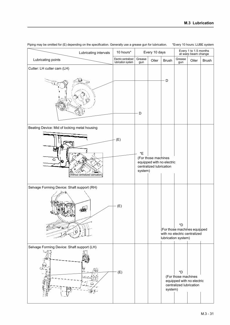
Piping may be omitted for (E) depending on the specification. Generally use a grease gun for lubrication. *Every 10 hours: LUBE system
10 hours* Every 10 days Every 1 to 1.5 months at warp beam change
Electric centrallzed lubrication system
Grease gun Oiler Brush Grease
gun Oiler Brush
Cutter: LH cutter cam (LH)
Beating Device: Mid of locking metal housing
Selvage Forming Device: Shaft support (RH)
Selvage Forming Device: Shaft support (LH)
Lubricating intervals
Lubricating points
D
D
*E(For those machines equipped with no electric centralized lubrication system)
(Without centralized lubrication)
(E)
(E)
*D(For those machines equipped with no electric centralized lubrication system)
(E) *D(For those machines equipped with no electric centralized lubrication system)
M.3 - 31
M. MAINTENANCE • DISASSEMBLY/REASSEMBLY/ADJUSTMENT • LUBRICATION
*Every 10 hours: LUBE system
10 hours* Every 10 days Every 1 to 1.5 months at warp beam change
Electric centrallzed lubrication system
Grease gun Oiler Brush Grease
gun Oiler Brush
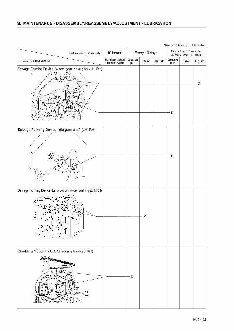
Selvage Forming Device: Wheel gear, drive gear (LH, RH)
Selvage Forming Device: Idle gear shaft (LH, RH)
Selvage Forming Device: Leno bobbin holder bushing (LH, RH)
Shedding Motion by CC: Shedding bracket (RH)
Lubricating intervals
Lubricating points
D
D
D
A
D
M.3 - 32
M.3 Lubrication
*Every 10 hours: LUBE system
10 hours* Every 10 days Every 1 to 1.5 months at warp beam change
Electric centrallzed lubrication system
Grease gun Oiler Brush Grease
gun Oiler Brush
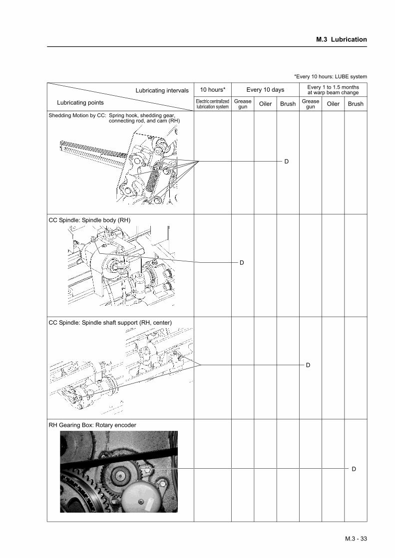
Shedding Motion by CC: Spring hook, shedding gear, connecting rod, and cam (RH)
CC Spindle: Spindle body (RH)
CC Spindle: Spindle shaft support (RH, center)
RH Gearing Box: Rotary encoder
Lubricating intervals
Lubricating points
D
D
D
D
M.3 - 33
M. MAINTENANCE • DISASSEMBLY/REASSEMBLY/ADJUSTMENT • LUBRICATION
*Every 10 hours: LUBE system
10 hours* Every 10 days Every 1 to 1.5 months at warp beam change
Electric centrallzed lubrication system
Grease gun Oiler Brush Grease
gun Oiler Brush
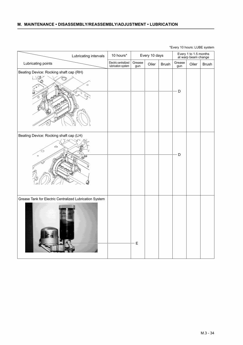
Beating Device: Rocking shaft cap (RH)
Beating Device: Rocking shaft cap (LH)
Grease Tank for Electric Centralized Lubrication System
Lubricating intervals
Lubricating points
D
D
E
M.3 - 34
M.3 Lubrication
[ 3 ] Oil ChangeIf oil contamination is excessive, replace with newlubricating oil irrelevant to the lubricant replacementintervals.
NOTE: If oil mixed with water or foreign matters iskept used, gears may be damaged. Oil mixed withwater will become yellowish.
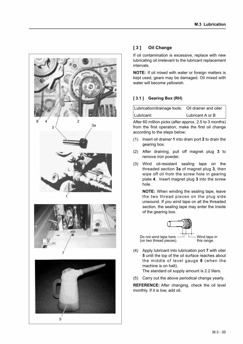
[ 3.1 ] Gearing Box (RH)
After 60 million picks (after approx. 2.5 to 3 months)from the first operation, make the first oil changeaccording to the steps below:
(1) Insert oil drainer 1 into drain port 2 to drain thegearing box.
(2) After draining, pull off magnet plug 3 toremove iron powder.
(3) Wind oil-resistant sealing tape on thethreaded section 3a of magnet plug 3, thenwipe off oil from the screw hole in gearingplate 4. Insert magnet plug 3 into the screwhole.
NOTE: When winding the sealing tape, leavethe two thread pieces on the plug sideunwound. If you wind tape on all the threadedsection, the sealing tape may enter the insideof the gearing box.
(4) Apply lubricant into lubrication port 7 with oiler5 until the top of the oil surface reaches aboutthe middle of level gauge 8 (when themachine is on halt).The standard oil supply amount is 2.2 liters.
(5) Carry out the above periodical change yearly.
REFERENCE: After changing, check the oil levelmonthly. If it is low, add oil.
8 43
23a
1
7
5
Lubrication/drainage tools: Oil drainer and oiler
Lubricant: Lubricant A or B
Do not wind tape here (on two thread pieces).
Wind tape in this range.
M.3 - 35
M. MAINTENANCE • DISASSEMBLY/REASSEMBLY/ADJUSTMENT • LUBRICATION
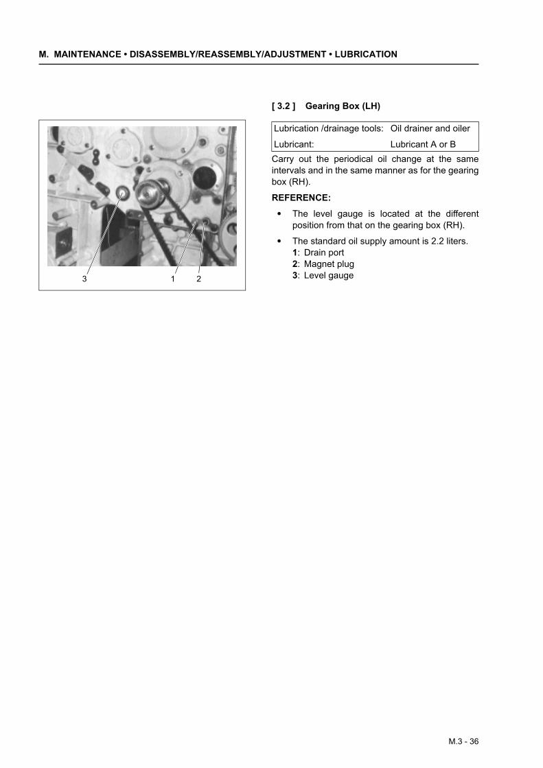
[ 3.2 ] Gearing Box (LH)
Carry out the periodical oil change at the sameintervals and in the same manner as for the gearingbox (RH).
REFERENCE:
• The level gauge is located at the differentposition from that on the gearing box (RH).
• The standard oil supply amount is 2.2 liters.1: Drain port2: Magnet plug3: Level gauge3 21
Lubrication /drainage tools: Oil drainer and oiler
Lubricant: Lubricant A or B
M.3 - 36

M.3 Lubrication
[ 3.3 ] Tappet Box (RH)
Exchange the whole oil at 60 million picks (about2.5 months) after the start of initial operation, andevery 12 months thereafter as described below.
(1) Place the oil tray under tappet box 1 andremove plug 2 for draining.
(2) If any foreign matters exist in the box, removethem thoroughly.
(3) Wrap oil-resistant seal tape (Nichias Corp9082 or equivalent) around the threaded por-tion of plug 2, wipe oil from the mounting holein the tappet box, and install the plug.
NOTE: When wrapping the seal tape, leavetwo threads on the plug side unwrapped.Wrapping the whole threaded area may causeseal tape entrance into the gearbox.
(4) Add the lubricating oil until its surface reachesthe level in the table below.
NOTE:
• Add oil while pouring it onto the tappet camand shaft.
• Check the oil level every month after the startof operation. Add oil if insufficient.
• Always install the tappet box cover 3 on thetappet box for waterproofing. If water entersby mistake, immediately replace the oil.When cleaning the loom, be especially carefulto prevent water entrance into the tappet box.
2 1
Tappet box (sectional view)
(A)
(B)
3
Lubrication/drainage tools: Oiler and oil receiver
Lubricant: Lubricant B
Oil level setting
Use only for spun cam (B) Elbow sleeve height
Use for filament cam (A) Upper level gauge seal
Add oil by pouring it onto the tappet cam and shaft. If there is a selvage cam, also pour oil sufficiently onto the selvage cam.
Do not wind tape here(on two thread pieces).
Wind tape inthis range.
M.3 - 37
M. MAINTENANCE • DISASSEMBLY/REASSEMBLY/ADJUSTMENT • LUBRICATION
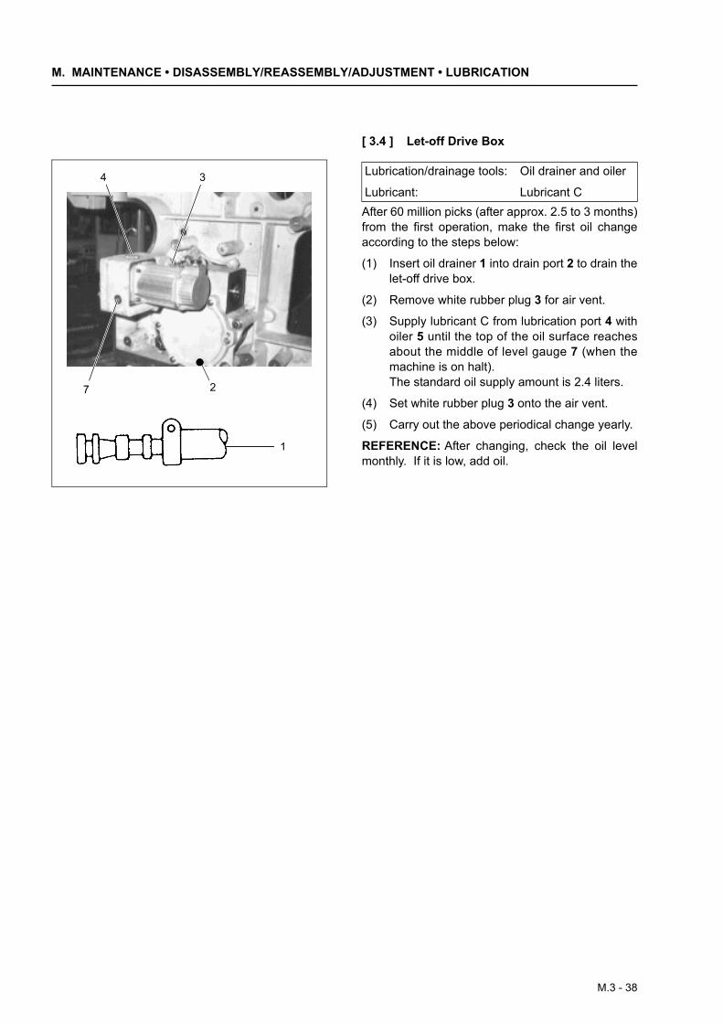
[ 3.4 ] Let-off Drive Box
After 60 million picks (after approx. 2.5 to 3 months)from the first operation, make the first oil changeaccording to the steps below:
(1) Insert oil drainer 1 into drain port 2 to drain thelet-off drive box.
(2) Remove white rubber plug 3 for air vent.
(3) Supply lubricant C from lubrication port 4 withoiler 5 until the top of the oil surface reachesabout the middle of level gauge 7 (when themachine is on halt).The standard oil supply amount is 2.4 liters.
(4) Set white rubber plug 3 onto the air vent.
(5) Carry out the above periodical change yearly.
REFERENCE: After changing, check the oil levelmonthly. If it is low, add oil.
7 2
4 3
1
Lubrication/drainage tools: Oil drainer and oiler
Lubricant: Lubricant C
M.3 - 38
M.3 Lubrication
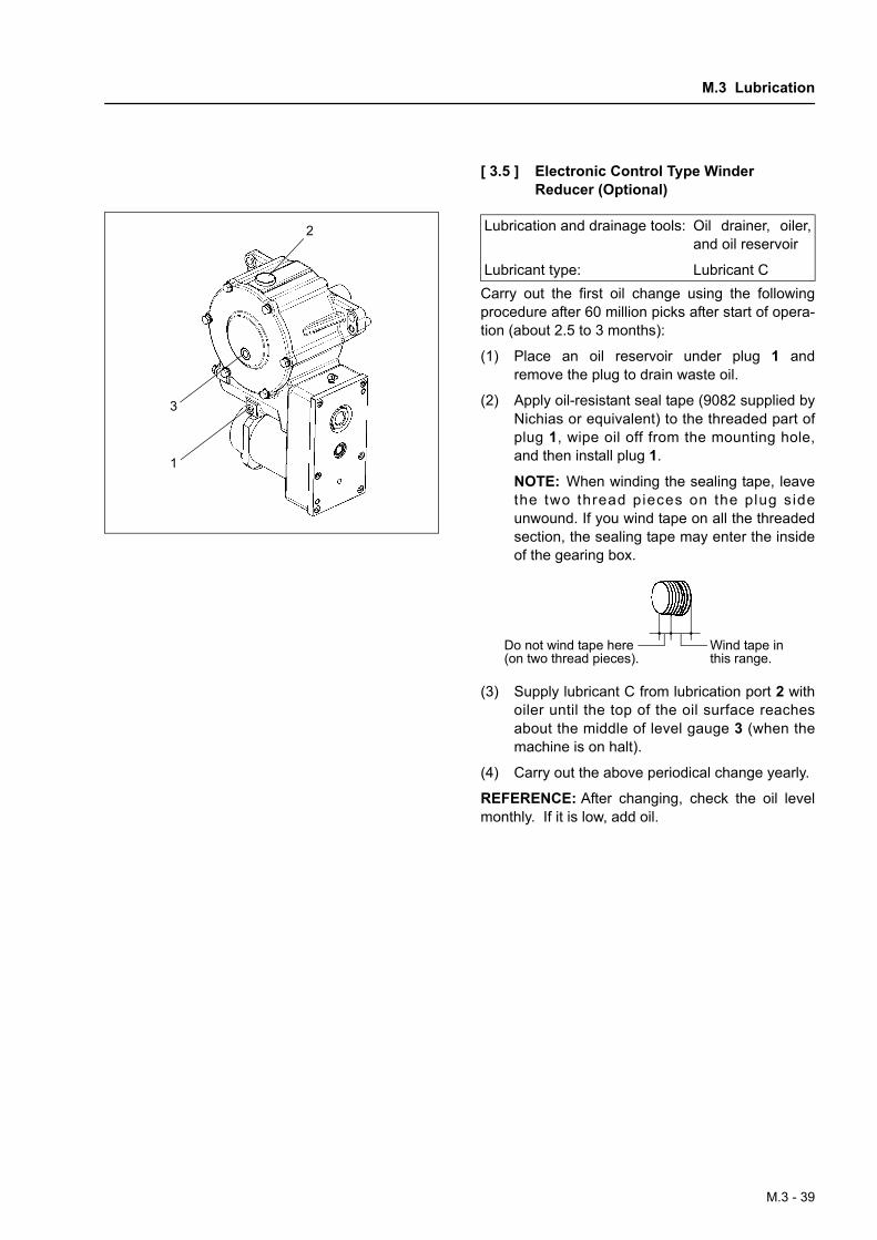
[ 3.5 ] Electronic Control Type Winder Reducer (Optional)
Carry out the first oil change using the followingprocedure after 60 million picks after start of opera-tion (about 2.5 to 3 months):
(1) Place an oil reservoir under plug 1 andremove the plug to drain waste oil.
(2) Apply oil-resistant seal tape (9082 supplied byNichias or equivalent) to the threaded part ofplug 1, wipe oil off from the mounting hole,and then install plug 1.
NOTE: When winding the sealing tape, leavethe two thread pieces on the plug sideunwound. If you wind tape on all the threadedsection, the sealing tape may enter the insideof the gearing box.
(3) Supply lubricant C from lubrication port 2 withoiler until the top of the oil surface reachesabout the middle of level gauge 3 (when themachine is on halt).
(4) Carry out the above periodical change yearly.
REFERENCE: After changing, check the oil levelmonthly. If it is low, add oil.
2
3
1
Lubrication and drainage tools: Oil drainer, oiler,and oil reservoir
Lubricant type: Lubricant C
Do not wind tape here (on two thread pieces).
Wind tape in this range.
M.3 - 39