Section 4 MicroStation Attributes - okladot.state.ok.us€¦ · Section 4 MicroStation Attributes...
19
Section 4 MicroStation Attributes Level Manager o Filters Level Display Levels, Color, Line Style, Line Weight, & Grayscale Scaling Line Styles Color Table/Grayscale Grayscale
Transcript of Section 4 MicroStation Attributes - okladot.state.ok.us€¦ · Section 4 MicroStation Attributes...
Section 4
MicroStation Attributes
Level Manager
o Filters
Level Display
Levels, Color, Line Style, Line Weight, & Grayscale
Scaling Line Styles
Color Table/Grayscale
Grayscale
Level Manager
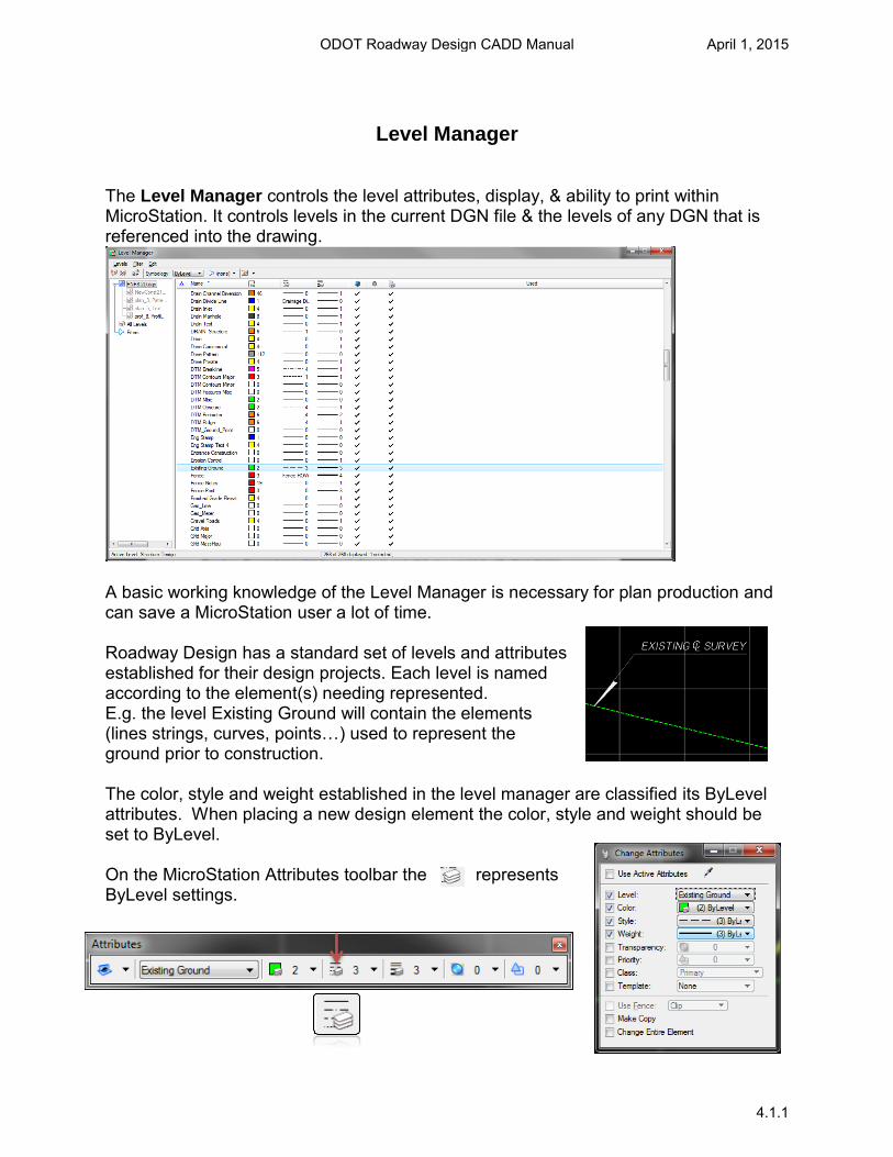
The Level Manager controls the level attributes, display, & ability to print within MicroStation. It controls levels in the current DGN file & the levels of any DGN that is referenced into the drawing.
A basic working knowledge of the Level Manager is necessary for plan production and can save a MicroStation user a lot of time.
Roadway Design has a standard set of levels and attributes established for their design projects. Each level is named according to the element(s) needing represented. E.g. the level Existing Ground will contain the elements (lines strings, curves, points…) used to represent the ground prior to construction.
The color, style and weight established in the level manager are classified its ByLevel attributes. When placing a new design element the color, style and weight should be set to ByLevel.
On the MicroStation Attributes toolbar the represents ByLevel settings.
ODOT Roadway Design CADD Manual April 1, 2015
4.1.1

Level Filters (Currently Under Development)
Filters are a useful way to group associated levels for the purposes of viewing or not viewing as a group. You can have DGN file with several hundred levels. Within these levels could be filters for different plan sheets such as Title Sheet, Typical Sheet, or CrossSection.
For example, a Title Sheet level filter would only displays levels that are used to construct a Title Sheet. Within this filter we can further break down the levels into subcategories such as Notes, Highway Symbols, etc.
Level Filters can be accessed from the Attributes toolbox.
If the Active Level Filter option is not visible on the toolbar, right-click the toolbar and select “Active Level Filter” from the display list to view it.
ODOT Roadway Design CADD Manual April 1, 2015
4.1.2
Level Display
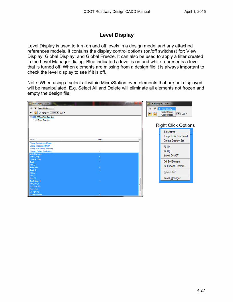
Level Display is used to turn on and off levels in a design model and any attached references models. It contains the display control options (on/off switches) for: View Display, Global Display, and Global Freeze. It can also be used to apply a filter created in the Level Manager dialog. Blue indicated a level is on and white represents a level that is turned off. When elements are missing from a design file it is always important to check the level display to see if it is off. Note: When using a select all within MicroStation even elements that are not displayed will be manipulated. E.g. Select All and Delete will eliminate all elements not frozen and empty the design file.
Right Click Options
ODOT Roadway Design CADD Manual April 1, 2015
4.2.1
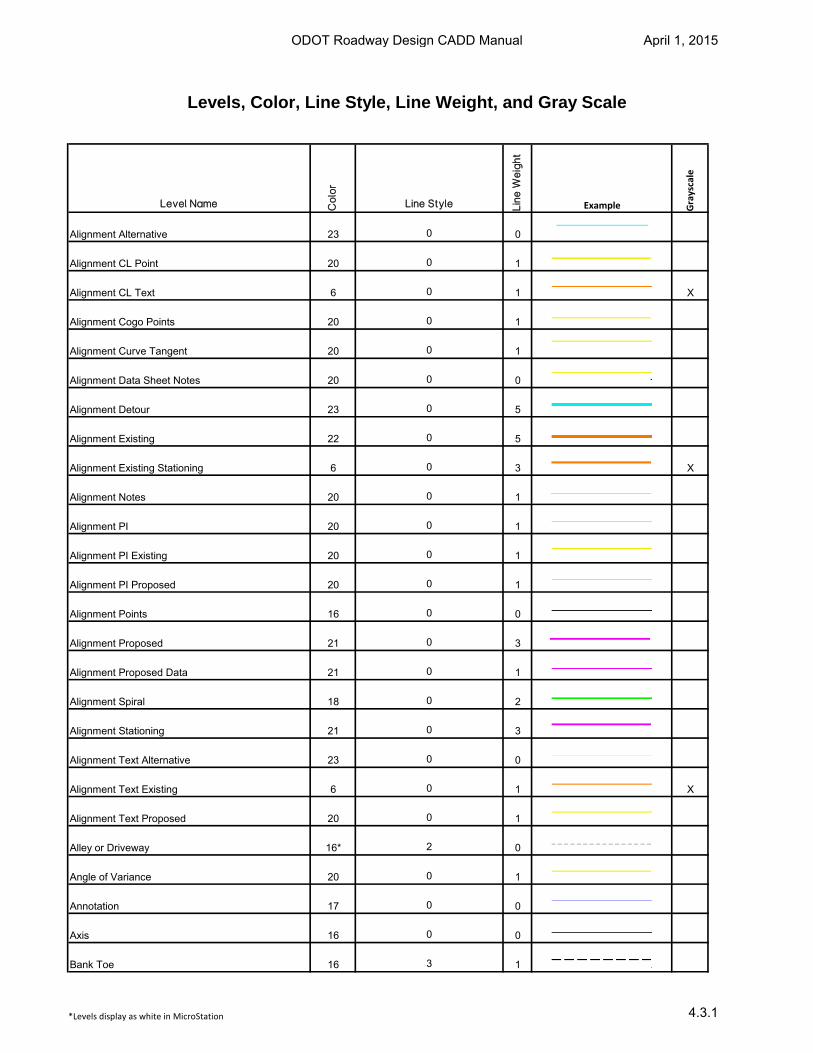
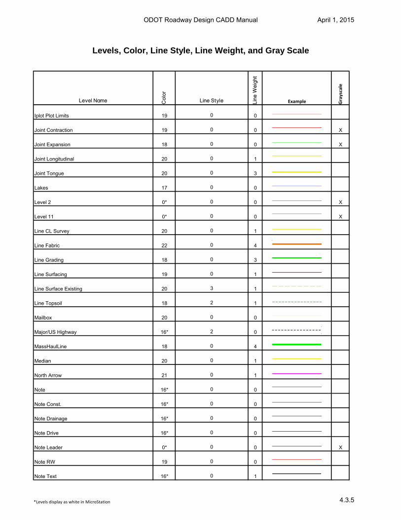
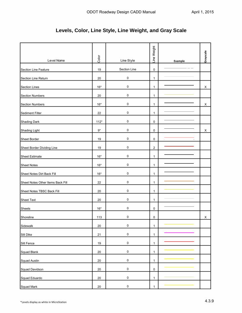
Levels, Color, Line Style, Line Weight, and Gray Scale
Level Name Co
lor
Line Style Lin
e W
eig
ht
Example Grayscale
Alignment Alternative 23 0 0
Alignment CL Point 20 0 1
Alignment CL Text 6 0 1 X
Alignment Cogo Points 20 0 1
Alignment Curve Tangent 20 0 1
Alignment Data Sheet Notes 20 0 0
Alignment Detour 23 0 5
Alignment Existing 22 0 5
Alignment Existing Stationing 6 0 3 X
Alignment Notes 20 0 1
Alignment PI 20 0 1
Alignment PI Existing 20 0 1
Alignment PI Proposed 20 0 1
Alignment Points 16 0 0
Alignment Proposed 21 0 3
Alignment Proposed Data 21 0 1
Alignment Spiral 18 0 2
Alignment Stationing 21 0 3
Alignment Text Alternative 23 0 0
Alignment Text Existing 6 0 1 X
Alignment Text Proposed 20 0 1
Alley or Driveway 16* 2 0
Angle of Variance 20 0 1
Annotation 17 0 0
Axis 16 0 0
Bank Toe 16 3 1
*Levels display as white in MicroStation
ODOT Roadway Design CADD Manual April 1, 2015
4.3.1
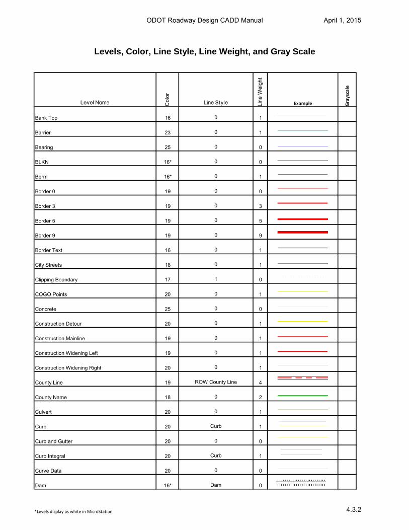
Levels, Color, Line Style, Line Weight, and Gray Scale
Level Name Co
lor
Line Style Lin
e W
eig
ht
Example Grayscale
Bank Top 16 0 1
Barrier 23 0 1
Bearing 25 0 0
BLKN 16* 0 0
Berm 16* 0 1
Border 0 19 0 0
Border 3 19 0 3
Border 5 19 0 5
Border 9 19 0 9
Border Text 16 0 1
City Streets 18 0 1
Clipping Boundary 17 1 0
COGO Points 20 0 1
Concrete 25 0 0
Construction Detour 20 0 1
Construction Mainline 19 0 1
Construction Widening Left 19 0 1
Construction Widening Right 20 0 1
County Line 19 ROW County Line 4
County Name 18 0 2
Culvert 20 0 1
Curb 20 Curb 1
Curb and Gutter 20 0 0
Curb Integral 20 Curb 1
Curve Data 20 0 0
Dam 16* Dam 0
*Levels display as white in MicroStation
ODOT Roadway Design CADD Manual April 1, 2015
4.3.2
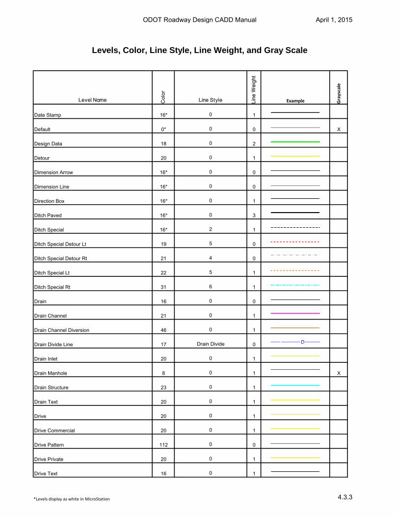
Levels, Color, Line Style, Line Weight, and Gray Scale
Level Name Co
lor
Line Style Lin
e W
eig
ht
Example Grayscale
Date Stamp 16* 0 1
Default 0* 0 0 X
Design Data 18 0 2
Detour 20 0 1
Dimension Arrow 16* 0 0
Dimension Line 16* 0 0
Direction Box 16* 0 1
Ditch Paved 16* 0 3
Ditch Special 16* 2 1
Ditch Special Detour Lt 19 5 0
Ditch Special Detour Rt 21 4 0
Ditch Special Lt 22 5 1
Ditch Special Rt 31 6 1
Drain 16 0 0
Drain Channel 21 0 1
Drain Channel Diversion 46 0 1
Drain Divide Line 17 Drain Divide 0
Drain Inlet 20 0 1
Drain Manhole 8 0 1 X
Drain Structure 23 0 1
Drain Text 20 0 1
Drive 20 0 1
Drive Commercial 20 0 1
Drive Pattern 112 0 0
Drive Private 20 0 1
Drive Text 16 0 1
*Levels display as white in MicroStation
ODOT Roadway Design CADD Manual April 1, 2015
4.3.3
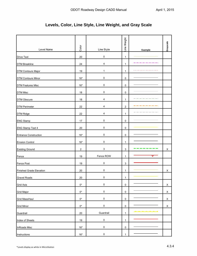
Levels, Color, Line Style, Line Weight, and Gray Scale
Level Name Co
lor
Line Style Lin
e W
eig
ht
Example Grayscale
Drive Text 20 0 1
DTM Breakline 24 4 1
DTM Contours Major 19 1 1
DTM Contours Minor 16* 0 0
DTM Features Misc 16* 0 0
DTM Misc 18 0 0
DTM Obscure 18 4 1
DTM Perimeter 22 4 2
DTM Ridge 22 4 1
ENG Stamp 17 0 0
ENG Stamp Text 4 20 0 0
Entrance Construction 16* 0 0
Erosion Control 16* 0 1
Existing Ground 2 3 3 X
Fence 19 Fence ROW 1
Fence Post 19 0 3
Finished Grade Elevation 20 0 1 X
Gravel Roads 20 0 1
Grid Axis 0* 0 0 X
Grid Major 0* 0 0 X
Grid MassHaul 0* 0 0 X
Grid Minor 0* 0 0 X
Guardrail 20 Guardrail 1
Index of Sheets 19 0 1
InRoads Misc 16* 0 0
Instructions 16* 0 1
*Levels display as white in MicroStation
ODOT Roadway Design CADD Manual April 1, 2015
4.3.4
Levels, Color, Line Style, Line Weight, and Gray Scale
Level Name Co
lor
Line Style Lin
e W
eig
ht
Example Grayscale
Iplot Plot Limits 19 0 0
Joint Contraction 19 0 0 X
Joint Expansion 18 0 0 X
Joint Longitudinal 20 0 1
Joint Tongue 20 0 3
Lakes 17 0 0
Level 2 0* 0 0 X
Level 11 0* 0 0 X
Line CL Survey 20 0 1
Line Fabric 22 0 4
Line Grading 18 0 3
Line Surfacing 19 0 1
Line Surface Existing 20 3 1
Line Topsoil 18 2 1
Mailbox 20 0 0
Major/US Highway 16* 2 0
MassHaulLine 18 0 4
Median 20 0 1
North Arrow 21 0 1
Note 16* 0 0
Note Const. 16* 0 0
Note Drainage 16* 0 0
Note Drive 16* 0 0
Note Leader 0* 0 0 X
Note RW 19 0 0
Note Text 16* 0 1
*Levels display as white in MicroStation
ODOT Roadway Design CADD Manual April 1, 2015
4.3.5
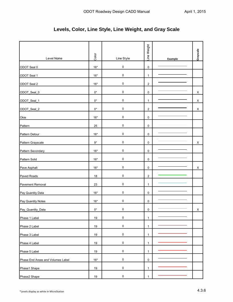
Levels, Color, Line Style, Line Weight, and Gray Scale
Level Name Co
lor
Line Style Lin
e W
eig
ht
Example Grayscale
ODOT Seal 0 16* 0 0
ODOT Seal 1 16* 0 1
ODOT Seal 2 16* 0 2
ODOT_Seal_0 0* 0 0 X
ODOT_Seal_1 0* 0 1 X
ODOT_Seal_2 0* 0 2 X
Okie 16* 0 0
Pattern 25 0 0
Pattern Detour 16* 0 0
Pattern Grayscale 9* 0 0 X
Pattern Secondary 16* 0 0
Pattern Solid 16* 0 0
Pave Asphalt 16* 0 0 X
Paved Roads 18 0 2
Pavement Removal 23 0 1
Pay Quantity Data 16* 0 0
Pay Quantity Notes 16* 0 0
Pay_Quantity_Data 0* 0 0 X
Phase 1 Label 19 0 1
Phase 2 Label 19 0 1
Phase 3 Label 19 0 1
Phase 4 Label 19 0 1
Phase 5 Label 19 0 1
Phase End Areas and Volumes Label 16* 0 0
Phase1 Shape 19 0 1
Phase2 Shape 19 0 1
*Levels display as white in MicroStation
ODOT Roadway Design CADD Manual April 1, 2015
4.3.6
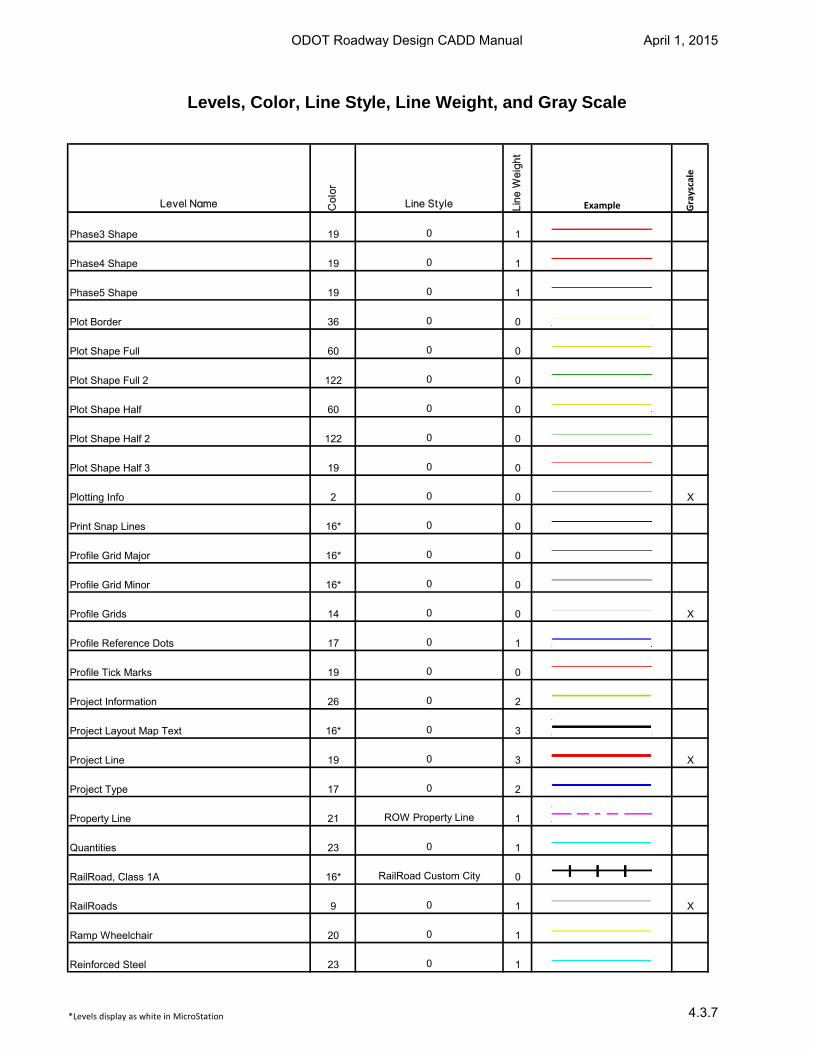
Levels, Color, Line Style, Line Weight, and Gray Scale
Level Name Co
lor
Line Style Lin
e W
eig
ht
Example Grayscale
Phase3 Shape 19 0 1
Phase4 Shape 19 0 1
Phase5 Shape 19 0 1
Plot Border 36 0 0
Plot Shape Full 60 0 0
Plot Shape Full 2 122 0 0
Plot Shape Half 60 0 0
Plot Shape Half 2 122 0 0
Plot Shape Half 3 19 0 0
Plotting Info 2 0 0 X
Print Snap Lines 16* 0 0
Profile Grid Major 16* 0 0
Profile Grid Minor 16* 0 0
Profile Grids 14 0 0 X
Profile Reference Dots 17 0 1
Profile Tick Marks 19 0 0
Project Information 26 0 2
Project Layout Map Text 16* 0 3
Project Line 19 0 3 X
Project Type 17 0 2
Property Line 21 ROW Property Line 1
Quantities 23 0 1
RailRoad, Class 1A 16* RailRoad Custom City 0
RailRoads 9 0 1 X
Ramp Wheelchair 20 0 1
Reinforced Steel 23 0 1
*Levels display as white in MicroStation
ODOT Roadway Design CADD Manual April 1, 2015
4.3.7
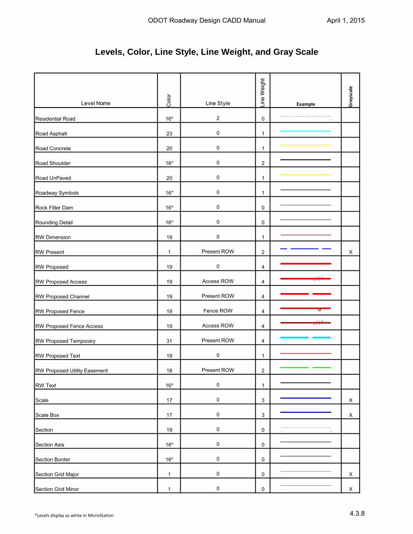
Levels, Color, Line Style, Line Weight, and Gray Scale
Level Name Co
lor
Line Style Lin
e W
eig
ht
Example Grayscale
Residential Road 16* 2 0
Road Asphalt 23 0 1
Road Concrete 20 0 1
Road Shoulder 16* 0 2
Road UnPaved 20 0 1
Roadway Symbols 16* 0 1
Rock Filter Dam 16* 0 0
Rounding Detail 16* 0 0
RW Dimension 19 0 1
RW Present 1 Present ROW 2 X
RW Proposed 19 0 4
RW Proposed Access 19 Access ROW 4
RW Proposed Channel 19 Present ROW 4
RW Proposed Fence 19 Fence ROW 4
RW Proposed Fence Access 19 Access ROW 4
RW Proposed Temporary 31 Present ROW 4
RW Proposed Text 19 0 1
RW Proposed Utility Easement 18 Present ROW 2
RW Text 16* 0 1
Scale 17 0 3 X
Scale Box 17 0 3 X
Section 19 0 0
Section Axis 16* 0 0
Section Border 16* 0 0
Section Grid Major 1 0 0 X
Section Grid Minor 1 0 0 X
*Levels display as white in MicroStation
ODOT Roadway Design CADD Manual April 1, 2015
4.3.8
Levels, Color, Line Style, Line Weight, and Gray Scale
Level Name Co
lor
Line Style Lin
e W
eig
ht
Example Grayscale
Section Line Feature 19 Section Line 0
Section Line Return 20 0 1
Section Lines 16* 0 1 X
Section Numbers 20 0 1
Section Numbers 16* 0 1 X
Sediment Filter 22 0 1
Shading Dark 112* 0 0
Shading Light 9* 0 0 X
Sheet Border 19 0 0
Sheet Border Dividing Line 19 0 2
Sheet Estimate 16* 0 1
Sheet Notes 16* 0 1
Sheet Notes Dirt Back Fill 16* 0 1
Sheet Notes Other Items Back Fill 22 0 1
Sheet Notes TBSC Back Fill 20 0 1
Sheet Text 20 0 1
Sheets 16* 0 0
Shoreline 113 0 0 X
Sidewalk 20 0 1
Silt Dike 21 0 1
Silt Fence 19 0 1
Squad Blank 20 0 1
Squad Austin 20 0 1
Squad Davidson 20 0 0
Squad Eduardo 20 0 1
Squad Mark 20 0 1
*Levels display as white in MicroStation
ODOT Roadway Design CADD Manual April 1, 2015
4.3.9

Levels, Color, Line Style, Line Weight, and Gray Scale
Level Name Co
lor
Line Style Lin
e W
eig
ht
Example Grayscale
Squad Mazloompour 20 0 1
Squad McIntosh 20 0 1
Squad Mohamed 20 0 1
Squad Murphy 20 0 1
Squad Russel 20 0 1
Squad Woods 20 0 1
Stamp Change in Plans 18 0 1
Stamp Final Field Meeting 19 0 1
Stamp for Information and Station Purposes Only 16* 0 0
Stamp Information Only 18 0 1
Stamp PIH 30% 19 0 1
Stamp PIH 75% 19 0 1
Stamp PIH and Utility Meeting 19 0 1
Stamp Prelim Disclaimer 19 0 1
Stamp Prelim Field Review and RW Util 18 0 1
Stamp Preliminary Plans 19 0 1
Stamp Proposed ROW 19 0 1
Stamp Revised Proposed RW 19 0 1 X
Stamp Revised Sheet 19 0 1
Stamp Revision Block 19 0 1
Stamp RW Utility Meeting 19 0 1
Stamp Send Comments 19 0 1
State Highway 19 0 2
State Map 16* 0 3
Stream 17 0 0
Strip Dividing 20 0 1
*Levels display as white in MicroStation
ODOT Roadway Design CADD Manual April 1, 2015
4.3.10
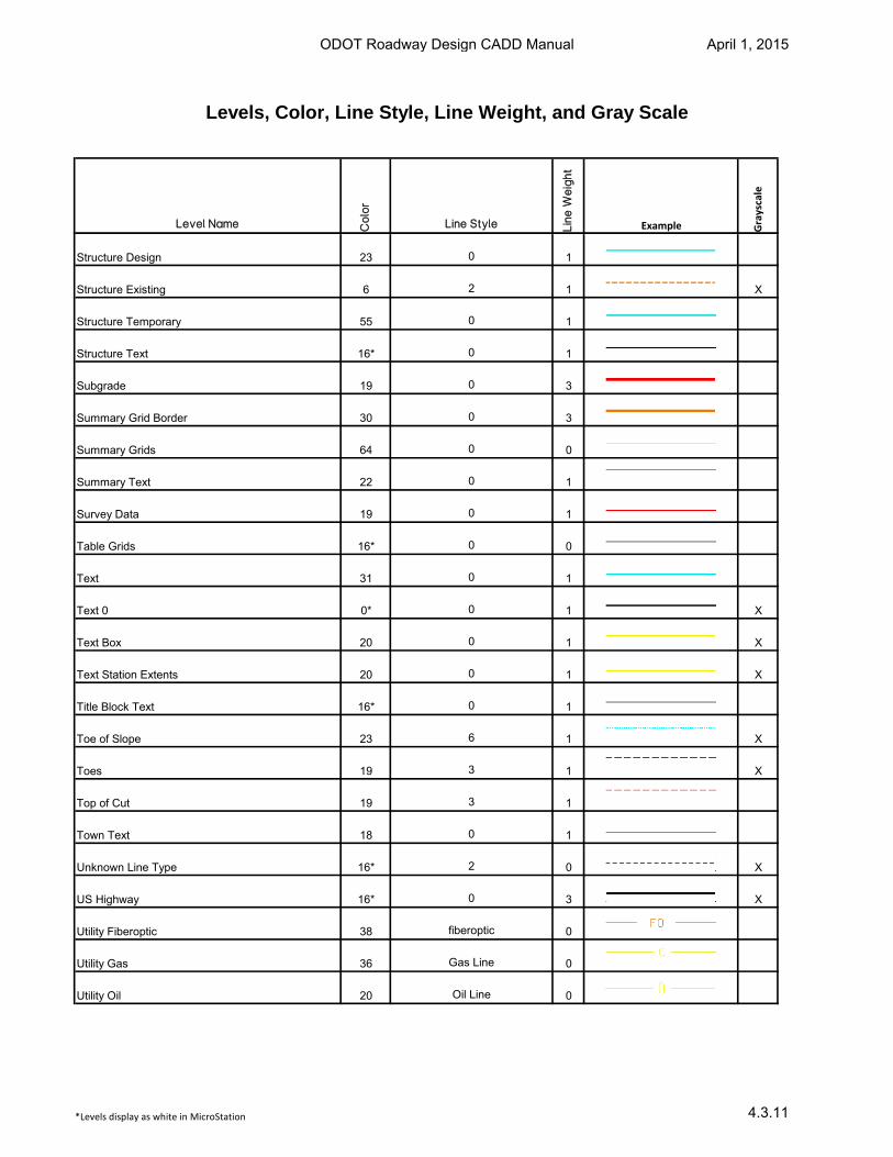
Levels, Color, Line Style, Line Weight, and Gray Scale
Level Name Co
lor
Line Style Lin
e W
eig
ht
Example Grayscale
Structure Design 23 0 1
Structure Existing 6 2 1 X
Structure Temporary 55 0 1
Structure Text 16* 0 1
Subgrade 19 0 3
Summary Grid Border 30 0 3
Summary Grids 64 0 0
Summary Text 22 0 1
Survey Data 19 0 1
Table Grids 16* 0 0
Text 31 0 1
Text 0 0* 0 1 X
Text Box 20 0 1 X
Text Station Extents 20 0 1 X
Title Block Text 16* 0 1
Toe of Slope 23 6 1 X
Toes 19 3 1 X
Top of Cut 19 3 1
Town Text 18 0 1
Unknown Line Type 16* 2 0 X
US Highway 16* 0 3 X
Utility Fiberoptic 38 fiberoptic 0
Utility Gas 36 Gas Line 0
Utility Oil 20 Oil Line 0
*Levels display as white in MicroStation
ODOT Roadway Design CADD Manual April 1, 2015
4.3.11
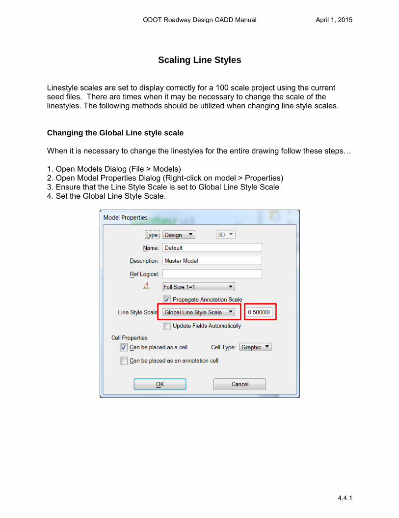
Scaling Line Styles
Linestyle scales are set to display correctly for a 100 scale project using the current seed files. There are times when it may be necessary to change the scale of the linestyles. The following methods should be utilized when changing line style scales.
Changing the Global Line style scale
When it is necessary to change the linestyles for the entire drawing follow these steps…
1. Open Models Dialog (File > Models)2. Open Model Properties Dialog (Right-click on model > Properties)3. Ensure that the Line Style Scale is set to Global Line Style Scale4. Set the Global Line Style Scale.
ODOT Roadway Design CADD Manual April 1, 2015
4.4.1
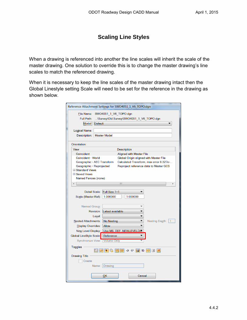
Scaling Line Styles
When a drawing is referenced into another the line scales will inherit the scale of the
master drawing. One solution to override this is to change the master drawing’s line
scales to match the referenced drawing.
When it is necessary to keep the line scales of the master drawing intact then the
Global Linestyle setting Scale will need to be set for the reference in the drawing as
shown below.
ODOT Roadway Design CADD Manual April 1, 2015
4.4.2
Scaling Line Styles
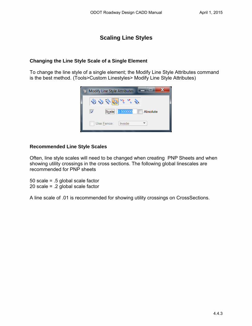
Changing the Line Style Scale of a Single Element
To change the line style of a single element; the Modify Line Style Attributes command is the best method. (Tools>Custom Linestyles> Modify Line Style Attributes)
Recommended Line Style Scales
Often, line style scales will need to be changed when creating PNP Sheets and when showing utility crossings in the cross sections. The following global linescales are recommended for PNP sheets
50 scale = .5 global scale factor 20 scale = .2 global scale factor
A line scale of .01 is recommended for showing utility crossings on CrossSections.
ODOT Roadway Design CADD Manual April 1, 2015
4.4.3
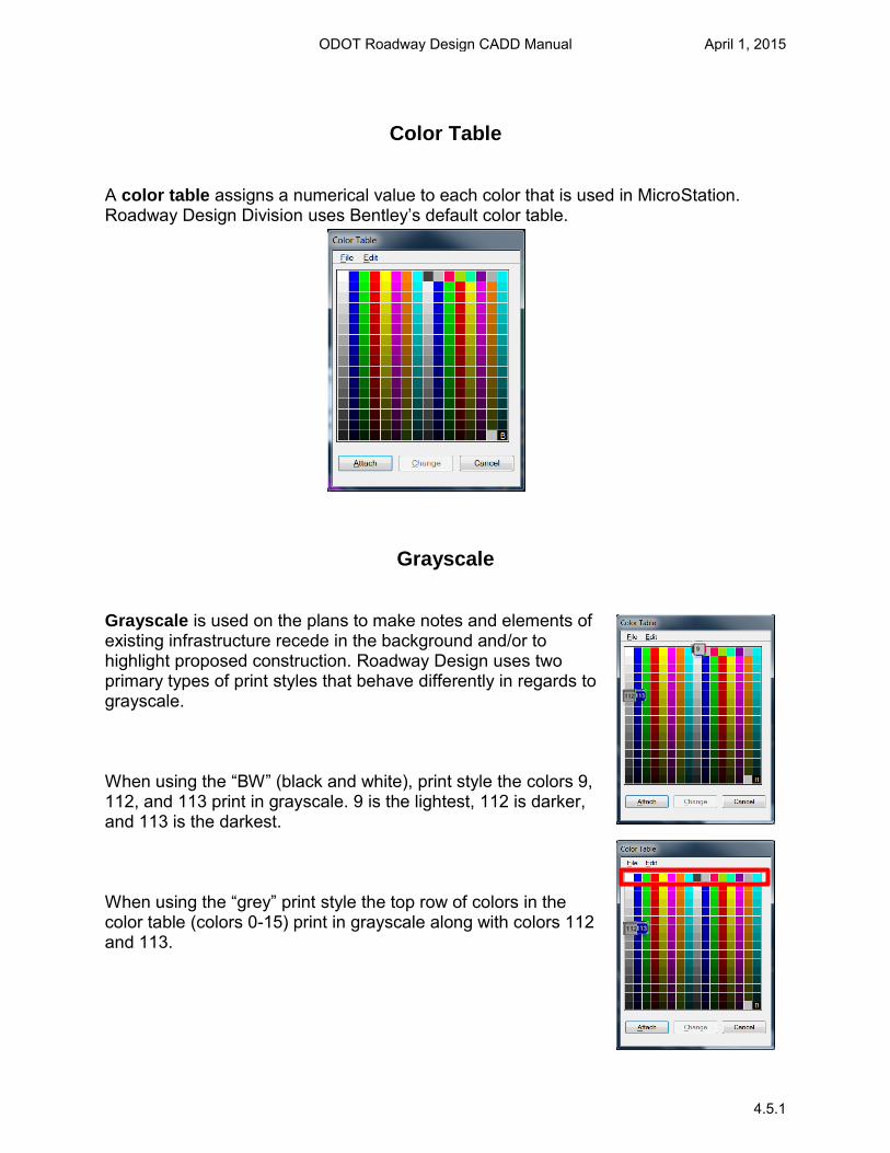
Color Table
A color table assigns a numerical value to each color that is used in MicroStation. Roadway Design Division uses Bentley’s default color table.
Grayscale
Grayscale is used on the plans to make notes and elements of existing infrastructure recede in the background and/or to highlight proposed construction. Roadway Design uses two primary types of print styles that behave differently in regards to grayscale.
When using the “BW” (black and white), print style the colors 9, 112, and 113 print in grayscale. 9 is the lightest, 112 is darker, and 113 is the darkest.
When using the “grey” print style the top row of colors in the color table (colors 0-15) print in grayscale along with colors 112 and 113.
ODOT Roadway Design CADD Manual April 1, 2015
4.5.1