
SECTION 21 13 29.10 FIRE SUPPRESSION PART 1 - GENERAL 1.1 ...
141
Akhiok RPSU Project Section 21 13 29.10 Modular Power Plant Assembly Fire Suppression 21 13 29.10 - 1 SECTION 21 13 29.10 FIRE SUPPRESSION PART 1 - GENERAL 1.1 SCOPE OF WORK A. The work involves design, installation, testing, and certification of an automatic fire suppression system for a power generation module. The module will contain three diesel engine generators as indicated. B. The module will be completely assembled off-site (shop fabricated), not field constructed in the community of Akhiok. All fire suppression system installation, and the initial testing will occur off site and shall include but not be limited to: 1. Design system in accordance with the latest adopted editions of all applicable codes and standards, manufacturer's requirements, these specifications, and the Drawings. 2. Obtain a State of Alaska, Fire Marshal Plan Review Permit. 3. Furnish and install a complete system. 4. Program fire control panel. 5. Acceptance testing and certification of completed system. 6. Preliminary operation training with Authority staff. 7. Preparation for shipping. 8. Operation and Maintenance Manuals including as-built drawings. C. Upon acceptance of shop fabrication installation and testing by the Authority, the module will be shipped to Akhiok, Alaska, for permanent installation and commissioning under a separate on-site contract. All final system testing, certification, commissioning, and training will occur on-site in Akhiok and will include but not be limited to: 1. Filling and charging system. 2. Final acceptance testing and certification of completed system. 3. Minimum four hours operation training with local operators and Authority staff. 1.2 RELATED SECTIONS A. Submittals including CAD drawings. B. Division 1. C. Division 23. D. Division 26.
Transcript of SECTION 21 13 29.10 FIRE SUPPRESSION PART 1 - GENERAL 1.1 ...

Akhiok RPSU Project Section 21 13 29.10 Modular Power Plant Assembly Fire Suppression
21 13 29.10 - 1
SECTION 21 13 29.10
FIRE SUPPRESSION
PART 1 - GENERAL
1.1 SCOPE OF WORK
A. The work involves design, installation, testing, and certification of an automatic fire suppression system for a power generation module. The module will contain three diesel engine generators as indicated.
B. The module will be completely assembled off-site (shop fabricated), not field constructed in the community of Akhiok. All fire suppression system installation, and the initial testing will occur off site and shall include but not be limited to:
1. Design system in accordance with the latest adopted editions of all applicable codes and standards, manufacturer's requirements, these specifications, and the Drawings.
2. Obtain a State of Alaska, Fire Marshal Plan Review Permit.
3. Furnish and install a complete system.
4. Program fire control panel.
5. Acceptance testing and certification of completed system.
6. Preliminary operation training with Authority staff.
7. Preparation for shipping.
8. Operation and Maintenance Manuals including as-built drawings.
C. Upon acceptance of shop fabrication installation and testing by the Authority, the module will be shipped to Akhiok, Alaska, for permanent installation and commissioning under a separate on-site contract. All final system testing, certification, commissioning, and training will occur on-site in Akhiok and will include but not be limited to:
1. Filling and charging system.
2. Final acceptance testing and certification of completed system.
3. Minimum four hours operation training with local operators and Authority staff.
1.2 RELATED SECTIONS
A. Submittals including CAD drawings.
B. Division 1.
C. Division 23.
D. Division 26.

Akhiok RPSU Project Section 21 13 29.10 Modular Power Plant Assembly Fire Suppression
21 13 29.10 - 2
1.3 QUALITY ASSURANCE
A. All equipment shall be new and shall be listed for the intended application. The entire system shall be designed and fabricated in accordance with recognized and acceptable engineering and industry practices.
B. Design shall be prepared by a registered mechanical engineer or technician with minimum NICET Level 3 certification. Designer shall have an appropriate State of Alaska design permit.
C. The Contractor shall be authorized by the fire suppression system manufacturer to furnish and install the specified system. Field installation shall be performed by technicians certified by the manufacturer to install the specified system.
1.4 REFERENCED STANDARDS:
A. National Fire Protection Association (NFPA) 750: Standard on Water Mist Fire Protection Systems.
B. Underwriters Laboratories (UL) UL 864 Control Units for Fire Protective Signaling Systems
C. National Fire Protection Association (NFPA) NFPA 72 National Fire Alarm Code
D. National Electrical Manufacturer's Association (NEMA).
1.5 SUBMITTALS
A. Provide submittals in the manner described herein and in Division 1.
B. Provide submittals for all products and systems described in Division 21 specifications and shown on the Drawings to demonstrate compliance with the requirements of the project. Submittal to include:
1. Manufacturer, model numbers and quantity of each device.
2. Manufacturer and model of control panel, including installed options.
3. Agent piping layout including size and quantity of nozzles.
4. Calculations.
5. Shop drawings shall indicate compliance with all requirements of the specifications and shall contain at a minimum:
a. Floor Plans and Isometrics for agent piping. b. Floor Plans and Diagrams for Wiring complete with circuit designation in
accordance with Wire Schedule on the Drawings (A-B-C-D-E). c. Panel and device installation details. d. Bill of Materials e. Installation notes and system Sequence of Operation.
C. Based upon review comments by the Authority, issue final revised submittal including final construction drawings.
D. Submit a copy of State of Alaska, Fire Marshal Plan Review Permit to the Authority.
E. Prior to testing, certification, and training provide Operation and Maintenance Manuals. Manuals to include system description, manufacturer's catalog information,

Akhiok RPSU Project Section 21 13 29.10 Modular Power Plant Assembly Fire Suppression
21 13 29.10 - 3
programming, instructions, operations and maintenance literature, Material Safety Data Sheets (MSDS) for extinguishing agent, and as-built drawings of completed system. Deliverables to include one bound copy plus 4 CD's with PDF format electronic files of the entire manual.
1.6 SUBSTITUTIONS
A. All substitutions shall be noted on equipment submittals.
1.7 WARRANTY
A. Division 1 - Closeout Requirements: Warranties.
B. Provide a one-year manufacturer's warranty covering all materials and workmanship of all products supplied. Warranty shall commence from the date of system certification.
PART 2 - MATERIALS
2.1 FIRE SUPPRESSION AGENT
A. A high pressure water mist fire suppression system shall be furnished, Marioff Hi-Fog or approved equal. In order for a substitution of the suppression system to be approved it must have at a minimum the following salient features:
1) The system must use water mist as the sole extinguishing agent.
2) The system must use high pressure (2,000 PSI nominal) nitrogen as the sole driving agent without the aid of any pumps.
3) The system shall be a single pipe system utilizing stainless steel tubing not exceeding 1” outside diameter.
4) The complete agent rack including all water and nitrogen storage for one zone of coverage shall not exceed the following dimensions: 4’-6” Long x 1’-4” Wide x 7’-6” High.
2.2 AGENT RACK AND WATER TANK
A. Wall or floor mounted racks shall be provided that contain the agent cylinders, nitrogen cylinder, and piping. Marioff Hi-Fog MAU 150 FS or approved equal.
B. The racks shall be designed for the appropriate seismic code and shall be adequately anchored to the building structure.
2.3 FIRE CONTROL PANEL
A. The Fire Control Panel shall be a Fike Cheetah XI-50 10-071-R1 or approved equal, and shall contain a microprocessor based Central Processing Unit (CPU). The CPU shall communicate with, supervise and control the following types of equipment used to make up the system: intelligent self-calibrating smoke and flame detectors, addressable modules, annunciators, and other system controlled devices.
B. Basic equipment to be included with Fire Control Panel shall be main board with display and keypad, door, hardware, and backbox for panel surface mount installation.
C. System Capacity and General Operation

Akhiok RPSU Project Section 21 13 29.10 Modular Power Plant Assembly Fire Suppression
21 13 29.10 - 4
1. The control panel shall be capable of 50 intelligent/addressable devices.
2. The system shall include two Class B (NFPA Style Y) programmable Notification Appliance Circuits. It shall also include three additional programmable Form-C alarm and trouble relays rated at a minimum of 2.0 amps @ 30 VDC.
3. The system shall support up to 99 programmable EIA-485 driven relays for an overall system capacity of 301 circuits.
4. The Fire Control Panel shall include a full featured operator interface control and annunciation panel that shall include a backlit Liquid Crystal Display, individual, color coded system status LEDs, and an alphanumeric keypad for the field programming and control of the fire system.
5. All programming or editing of the existing program in the system shall be achieved without special equipment, and without interrupting the alarm monitoring functions of the Fire Control Panel.
6. The Fire Control Panel shall provide the following features:
a. Automatic detect test and drift compensation to extend detector accuracy over life (smoke and flame detectors monitored and automatically calibrated)
b. Sensitivity Test, meeting requirements of NFPA 72, Chapter 5.
c. Maintenance Alert to warn of excessive smoke detector dirt or dust accumulation.
d. System Status Reports to display.
e. Positive Alarm Sequence pre-signal, meeting NFPA 72 3-8.3 requirements.
f. Periodic Detector Test, conducted automatically by software.
g. Pre-alarm for advanced fire warning.
h. Cross Zoning with the capability of: counting two detectors in alarm, two software zones in alarm, or one smoke detector and one thermal detector.
i. Walk Test, with check for two detectors set to same address.
j. Adjustable delay and discharge timers.
k. The detector software shall meet NFPA 72, Chapter 7 requirements and be certified by UL as a calibrated sensitivity test instrument.
l. The detector software shall allow manual or automatic sensitivity adjustment.
m. Event history file in nonvolatile memory.
n. Panel to have abort option to manually prevent release of extinguishing agent.
o. Battery back-up in the event of normal AC power failure.
p. Unit to be able to release extinguishing agent in at least two independent hazard zones.

Akhiok RPSU Project Section 21 13 29.10 Modular Power Plant Assembly Fire Suppression
21 13 29.10 - 5
2.4 SECONDARY POWER SOURCE BATTERIES
A. Secondary power shall be provided by 12 volt, gelled electrolyte batteries. The batteries shall be completely maintenance free. Fluid level checks and refilling shall not be required.
B. Batteries shall have sufficient capacity to power the fire system for not less than twenty-four hours standby operation plus 30 minutes of alarm upon a normal AC power failure. Note that this is in excess of minimum NFPA requirements.
2.5 HEAT DETECTOR
A. UL Listed, adjustable temperature heat detector. Fike 60-1039 or approved equal. Set to activate at 135°F for normal temperature and 190°F for high temperature.
2.6 FLAME (OPTICAL) DETECTOR
A. UL Listed, flame detectors shall be multi-spectrum, electro-optical, automatic calibrating, digital fire detectors. Fire Sentry Corporation Model SS4-A2 or approved equal. Install on SM4 swivel mount.
2.7 SMOKE (PHOTOELECTRIC) DETECTOR
A. UL Listed, automatic calibrating type, photoelectric smoke detector. Detector to be addressable and provide analog signal to the control panel which may be used for maintenance of detector. Fike 63-1052 or approved equal.
2.8 ANNUNCIATORS
A. Interior Annunciator (Alarm and Discharge) - UL Listed, Horn/strobe combination, minimum 75 candela. Gentex GEC3-24WR or approved equal.
B. Exterior Annunciator (Alarm) - Weatherproof, UL Listed horn/strobe combination, minimum 75 candela. Gentex WGEC24-75WR or approved equal.
C. Exterior Strobe (Discharge) - Weatherproof, UL Listed strobe, minimum 75 candela. Gentex WGEC24-75WR or approved equal.
2.9 MANUAL PULL STATION
A. Manual pull station(s) shall be UL Listed, addressable, double action, and provide visible indication that station has been operated. Fike 02-3710 or approved equal.
2.11 DEVICE MONITORING MODULES
A. UL Listed modules designed for use with intelligent and addressable equipment as required. Fike Series 55 or approved equal.
2.12 PLACARDS
A. Provide placards in compliance with NFPA as required. Provide additional warning placards as indicated on the plan in accordance with the Placard Schedule.
2.13 RACEWAYS AND CONDUCTORS
A. Route all wiring in separate dedicated raceways for all fire suppression system wiring at no cost to Contractor. All raceways shall be electrical metallic tubing (EMT). All raceways, junction boxes, pull boxes, and cover plates shall be painted red.

Akhiok RPSU Project Section 21 13 29.10 Modular Power Plant Assembly Fire Suppression
21 13 29.10 - 6
B. All conductors shall be soft drawn copper, Type XHHW insulation; 600V and 75C rated; gauge and color as indicated by service in accordance with the following schedule:
120V AC Power - 12 AWG, stranded, color per station service scheme.
24V DC Power, Detection, and Alarm Circuits - 14 AWG, color in accordance with the Wire Schedule.
2.14 NOZZLES
A. In Total Flooding and Local Application zones nozzles shall be open spray head type, Marioff 4S 1MC 8MB 1100 or approved equal.
2.15 PIPING
A. Contractor shall furnish, install, and pressure test agent discharge tubing/piping in accordance with manufacturer's recommendations.
2.16 SUPPORT
A. Contractor shall furnish and install industry standard hangers for agent discharge piping, raceways, panel and all devices.
2.17 FITTINGS, VALVES, CONTROLS, AND DEVICES
A. Contractor shall furnish and install all required fittings, valves, control devices, and accessories as required to provide the types of coverage required for each zone as indicated on the Drawings.
PART 3 - EXECUTION
3.1 DESIGN
A. Design fire suppression system with two zones of coverage as shown on the Drawings.
1. Zone 1 (Generation Room) shall contain agent rack, discharge piping and nozzles. Two flame detectors shall be cross-zoned so that any one detector will set off alarm and shut-down generators. Any second detector will begin a 30 second countdown to agent release. Two high temperature heat detectors shall be cross-zoned in the same sequence as the flame detectors. Exit shall have a manual “Agent Release” pull station which will begin a 30 second countdown to agent release when activated.
2. Zone 2 (Control Room) shall contain the control panel, one smoke detector and one normal temperature heat detector. Either detector will set off alarm and will shut-down generators. Exit shall have a manual “Agent Release” pull station which will begin a 30 second countdown to agent release when activated.
B. Provide annunciators and other devices where specifically indicated on the Drawings.
3.2 INSTALLATION - GENERAL
A. The system shall be installed in accordance with the Contract Documents, the approved submittal, and all manufacturer's requirements.
B. Contractor shall perform all work with skilled craftsmen specializing in said work with all required certifications. Install all materials in a neat, orderly, and secure fashion, as

Akhiok RPSU Project Section 21 13 29.10 Modular Power Plant Assembly Fire Suppression
21 13 29.10 - 7
required by these specifications, manufacturer’s requirements, and commonly recognized standards of good workmanship.
3.3 INSTALLATION – SHOP MODULE ASSEMBLY
A. Upon completion of shop testing, all water shall be drained and/or blown out of the system to prevent freeze damage and the batteries shall be disconnected.
B. The system shall be left with one fully charged nitrogen cylinder installed in the rack plus one fully charged spare nitrogen cylinder shipped loose with the module.
3.4 INSTALLATION – ON SITE
A. As previously specified, the final testing and commissioning will occur on site under a separate contract. The on-site work by others will include but not be limited to:
1. Filling and charging systems.
2. Final acceptance testing and certification of completed systems.
3. Minimum four hours operation training at each site with local operators and Authority staff.
4. Verify that each system has one fully charged nitrogen cylinder installed in the rack plus one fully charged spare nitrogen cylinder.
END OF SECTION

Akhiok RPSU Project Section 23 05 00 Modular Power Plant Assembly Common Work Results for Mechanical
23 05 00 - 1
SECTION 23 05 00
COMMON WORK RESULTS FOR MECHANICAL
PART 1 - GENERAL
1.1 SCOPE OF WORK
A. The work to be included in these and all other mechanical subsections shall consist of providing, installing, adjusting and setting into proper operation complete and workable systems for all items shown on the Drawings, described in the specifications or reasonably implied. This shall include the planning and supervision to coordinate the work with other crafts and to maintain a proper time schedule for delivery of materials and installation of the work.
B. Section includes:
1. General mechanical work.
2. Painting and marking.
3. Valve tags, signs, and placards.
4. Flashing and sealing.
1.2 RELATED SECTIONS
A. Division 1
B. All other Division 23 Specifications
C. Divisions 21 and 26
1.3 PROJECT RECORD DRAWINGS
A. In addition to other requirements of Division 1, mark up a clean set of drawings as the work progresses to show the dimensioned location and routing of all mechanical work which will become permanently concealed. Show routing of work in concealed blind spaces within the building.
B. Provide one set of drawings clearly marked up with all as-built information to the Authority within two weeks of completion.
C. At completion of project, deliver these drawings to the Authority and obtain a written receipt.
1.4 SUBMITTALS
A. Provide submittals for all products and systems described in Division 23 specifications and shown on the Drawings to demonstrate compliance with the requirements of the project. Provide submittals in the manner described herein and in Division 1.
B. Painting and Marking: Submit manufacturers catalog literature for each product required.
C. Valve Tags: Submit manufacturers catalog literature for tags as indicated on the Schedule on Sheet M1.2.

Akhiok RPSU Project Section 23 05 00 Modular Power Plant Assembly Common Work Results for Mechanical
23 05 00 - 2
D. Signs and Placards: Submit manufacturers catalog literature as indicated on the Schedule on Sheet M1.2.
E. Equipment: Submit manufacturers catalog literature for each item indicated on the Mechanical Schedules on Sheet M1.1 under the Division 23 Sections that follow. See specific requirements under each section.
1.5 RECEIVING AND HANDLING
A. See general conditions and the general requirements in Division 1 regarding material handling.
B. Deliver packaged materials to the jobsite in unbroken packaging with manufacturer’s label, and store to facilitate inspection and installation sequence.
C. Protect all materials and equipment during the duration of construction work against contamination and damage. Replace or repair to original manufactured condition any items damaged during construction. Immediately report any items found damaged to the Authority prior to commencing construction.
1.6 ENVIRONMENTAL REQUIREMENTS
A. Division 1 - Material and Equipment: Storage and protection.
1.7 QUALITY ASSURANCE
A. Division 1 - Quality Control
B. Perform all work in accordance with the latest adopted editions of the International Fire Code, the International Building Code, and the International Mechanical Code including State of Alaska amendments. Comply with all applicable State and Federal regulations.
C. Perform work with skilled craftsman specializing in said work. Install all materials in a neat and orderly, and secure fashion as required by specifications and commonly recognized standards of good workmanship.
1.8 SCHEDULE OF WORK
A. The work must be expedited and close coordination will be required in executing the work. The various trades shall perform their portion of the work at such times as directed so as to meet scheduled completion dates, and to avoid delaying any other trade.
B. The Authority will set up completion dates. Each Contractor shall cooperate in establishing these times and locations and shall process his work so as to ensure the proper execution of it.
1.9 SUBSTANTIAL COMPLETION
A. Contact the Authority one week prior to completion of all work to schedule substantial completion inspection. The Authority will generate a punchlist of corrective action items during the inspection. Work will not be considered complete until all corrective action items in the Authority’s punch list have been satisfactorily completed and photographic or other positive documentation has been provided to the Authority.

Akhiok RPSU Project Section 23 05 00 Modular Power Plant Assembly Common Work Results for Mechanical
23 05 00 - 3
1.10 COOPERATION AND CLEANING UP
A. The Contractor for the work under each section of the specifications shall coordinate his work with the work described in all other sections of the specifications, and shall carry on his work in such a manner that none of the work under any section of these specifications shall be handicapped, hindered or delayed at any time.
B. At all times during the progress of the work, the Contractor shall keep the premises clean and free of unnecessary materials and debris. The Contractor shall, on direction at any time from the Authority, clear any designated area or areas of materials and debris. On completion of any portion of the work, the Contractor shall remove from the premises all tools and machinery and all debris occasioned by the work, leaving the premises free of all obstructions and hindrances.
1.11 SPECIAL CONDITIONS
A. Ensure that the appropriate safety measures are implemented and the all workers are aware of the potential hazards from electrical shock, burn, rotating fans, pulleys, belts, hot manifolds, noise, etc. associated with working near power generation and control equipment.
1.12 WARRANTY
A. Division 1 - Closeout Requirements: Warranties.
PART 2 - PRODUCTS
2.1 MATERIALS AND EQUIPMENT
A. Provide all equipment and materials required for a complete system.
B. All equipment and materials supplied under this Contract are new unless specifically indicated as existing. Where additional or replacement items are required, provide like items by the same manufacturer to the maximum extent practical.
C. Install all material and equipment in accordance with manufacturer’s installation instructions and recommendations unless specifically indicated otherwise.
2.2 PAINTING
A. Carbon Steel Pipe - Paint all exposed carbon steel pipe that is not insulated except for engine exhaust. Wire brush and wipe down with solvent. Prime and finish with two coats of direct to metal alkyd enamel, Sherwin Williams DTM or approved equal, color Structural Gray 4031.
B. Paint all steel fabrications and tanks. Sandblast or wire brush to bare metal and wipe down with solvent. Prime and finish with two coats of self-priming epoxy, Sherwin Williams Macropoxy 646 or approved equal, color Structural Gray 4031.
C. Touch-up – finish all cut ends and damaged surfaces of galvanized and zinc plated supports and fasteners with spray on Cold Galvanizing Compound, ZRC or approved equal. Touch up paint on fabricated items to match original.
Akhiok RPSU Project Section 23 05 00 Modular Power Plant Assembly Common Work Results for Mechanical
23 05 00 - 4
2.3 VALVE TAGS
A. Specific Function Valve Tags – For all valves marked with a specific function, provide tags color coded and worded as indicated on the Schedule on Sheet M1.2.
B. Standard Valve Tags – For all valves not marked with a specific function, provide NO/NC tags as indicated on the schedules.
C. Install all tags as noted.
2.4 SIGNS AND PLACARDS
A. Provide decals and sign boards, color coded and worded as indicated on the Schedule on Sheet M1.2. Install as noted.
2.5 PIPE MARKING
A. Install flow arrows on diesel fuel, used oil, cooling, and heat recovery piping. On insulated piping install flow arrows over jackets. Black or white arrows over colored backgrounds, self-adhesive vinyl, Seton arrows on roll or approved equal. Background color scheme to match the Specific Function Valve Tags.
2.6 FLASHING AND SEALING
A. Caps & Coverings: Steel, 16 gauge minimum.
B. For penetration of all interior wall penetrations seal with polyurethane caulking.
C. Note that the drawings indicate removal of piping through exterior walls prior to shipping. Flashing and seal of all piping exterior wall penetrations shall be performed as part of the on site installation under a separate contract.
PART 3 - EXECUTION
3.1 DRAWINGS
A. The mechanical Drawings are generally diagrammatic and do not necessarily show all features of the required work. Provide all equipment and materials required for a complete system. Complete details of the building which affect the mechanical installation may not be shown. For additional details, see other Drawings which may include electrical, architectural, structural, and civil. Coordinate work under this section with that of all related trades.
B. Contractor to field verify all dimensions and conditions prior to start of construction. Immediately contact the Authority for clarification of questionable items or apparent conflicts.
3.2 CUTTING, FITTING, REPAIRING, PATCHING, AND FINISHING
A. Where previously completed building surfaces or other features must be cut, penetrated, or otherwise altered, such work shall be carefully laid out and patched to the original condition. Perform work only with craftsmen skilled in their respective trades.

Akhiok RPSU Project Section 23 05 00 Modular Power Plant Assembly Common Work Results for Mechanical
23 05 00 - 5
B. Do not cut, drill, or notch structural members unless specifically approved by the Authority. Minimize penetrations and disruption of building features.
C. Seal all exterior ceiling and wall penetrations as indicated. Where exterior wall penetrations are accessible from the inside seal both interior and exterior surfaces as indicated.
3.3 EXAMINATION
A. Check materials for damage that may have occurred during shipment. Repair damaged materials as required or replace with new materials.
3.4 INSTALLATION OF EQUIPMENT
A. Check materials for damage that may have occurred during shipment. Repair damaged materials as required or replace with new materials
B. Unless otherwise indicated, support all equipment and install in accordance with manufacturer's recommendations and approved submittals.
C. Maintain manufacturer's recommended minimum clearances for access and maintenance.
D. Where equipment is to be anchored to structure, furnish and locate necessary anchoring and vibration isolation devices.
E. Furnish all structural steel, such as angles, channels, beams, etc. required to support all piping, ductwork, equipment and accessories installed under this Division. Use structural supports suitable for equipment specified or as indicated. In all cases, support design will be based upon data contained in manufacturer's catalog.
F. Openings: Arrange for necessary openings in buildings to allow for admittance and reasonable maintenance or replacement of all apparatus furnished.
3.5 SCOPE OF ISOLATION AND RESTRAINT WORK
A. All vibrating equipment and the interconnecting pipe and ductwork shall be isolated to eliminate the transmission of objectionable noise and vibration from the structure.
B. Mechanical equipment shall be carefully checked upon delivery for proper mechanical performance, which shall include proper noise and vibration operation.
C. All installed rotating equipment with excessive noise and/or vibration, which cannot be corrected in place, shall be replaced at no cost to the Authority.
END OF SECTION

Akhiok RPSU Project Section 23 05 29 Modular Power Plant Assembly Hangers and Supports for Piping and Equipment
23 05 29 - 1
SECTION 23 05 29
HANGERS AND SUPPORTS FOR PIPING AND EQUIPMENT
PART 1 - GENERAL
1.1 SUMMARY
A. Section includes:
1. Pipe hangers and supports.
2. Hanger rods.
3. Formed steel channel.
1.2 RELATED SECTIONS
A. Section 23 05 00 – Common Work Requirements for Mechanical
B. Section 23 21 13 - Hydronic Piping
C. Section 23 11 13 - Fuel and Lube Oil Piping
D. Section 23 35 16.10 - Engine Exhaust and Crank Vent Piping
E. Section 26 05 29 - Hangers and Supports for Electrical Systems
1.3 REFERENCES
A. American Society of Mechanical Engineers:
1. ASME B31.1 - Power Piping.
2. ASME B31.9 - Building Services Piping.
B. ASTM International:
1. ASTM F708 - Standard Practice for Design and Installation of Rigid Pipe Hangers.
C. American Welding Society:
1. AWS D1.1 - Structural Welding Code - Steel.
D. Manufacturers Standardization Society of the Valve and Fittings Industry:
1. MSS SP 58 - Pipe Hangers and Supports - Materials, Design and Manufacturer.
2. MSS SP 69 - Pipe Hangers and Supports - Selection and Application.
3. MSS SP 89 - Pipe Hangers and Supports - Fabrication and Installation Practices.
1.4 SUBMITTALS
A. Provide submittals for all products and systems described herein. Provide in accordance with the requirements of Section 23 05 00 - Common Work Results for Mechanical and Division 1.
B. Product Data: Hangers and Supports: Submit manufacturers catalog data including load capacity. Indicate finish for interior and exterior applications.

Akhiok RPSU Project Section 23 05 29 Modular Power Plant Assembly Hangers and Supports for Piping and Equipment
23 05 29 - 2
C. Design Data: Indicate load carrying capacity of trapeze, multiple pipe, and riser support hangers. Indicate calculations used to determine load carrying capacity of trapeze, multiple pipe, and riser support hangers.
1.5 QUALITY ASSURANCE
A. Division 1 – Quality Control
B. Conform to applicable code for support of coolant and hydronic piping.
C. Perform Work in accordance with State of Alaska Standards.
1.6 QUALIFICATIONS
A. Manufacturer: Company specializing in manufacturing Products specified in this section with minimum three years documented experience.
B. Installer: Company specializing in performing Work of this section.
1.7 DELIVERY, STORAGE, AND HANDLING
A. Accept materials on site in original factory packaging, labeled with manufacturer's identification.
B. Protect from weather and construction traffic, dirt, water, chemical, and damage, by storing in original packaging.
1.8 FIELD MEASUREMENTS
A. Verify field measurements prior to fabrication.
PART 2 - PRODUCTS
2.1 STRUCTURAL STEEL
A. Miscellaneous shapes and plate: ASTM A-36.
B. Rectangular tubing: ASTM A-500 Grade B.
C. Structural Pipe: ASTM A-53 or ASTM A-106B.
D. Paint as indicated.
2.2 PIPE HANGERS AND SUPPORTS
A. Support equipment and raceways on strut, brackets, trapeze hangers, or as detailed. Anvil, B-Line, Grinnell, Unistrut, or approved equal.
2.3 FORMED STEEL CHANNEL
A. Strut: Cold formed mild steel channel strut, pre-galvanized finish and slotted back unless specifically indicated otherwise.
B. Standard Strut: 12 gauge thick steel, 1-5/8” x 1-5/8”, B-line B22-SH-Galv or equal.
C. Double Strut: 12 gauge thick steel, 1-5/8” x 3-1/4”, B-line B22A-SH-Galv or equal.
D. Shallow Strut: 14 gauge thick steel, 1-5/8” x 13/16”, B-line B54-SH-Galv or equal.

Akhiok RPSU Project Section 23 05 29 Modular Power Plant Assembly Hangers and Supports for Piping and Equipment
23 05 29 - 3
E. Where strut is welded to tanks or structures provided plain (unfinished black) solid back strut: 12 gauge thick steel, 1-5/8” x 1-5/8”, B-line B22-PLN or approved equal.
F. On all exterior installations provide hot dip galvanized strut and fittings.
2.4 FITTINGS AND ACCESSORIES
A. Provide fittings, brackets, channel nuts, and accessories designed specifically for use with specified channel strut. Zinc plated carbon steel except for exterior installations provide hot dip galvanized.
B. Pipe Clamps: Two piece pipe clamp designed to support pipe tight to strut, B-line B20##, or approved equal, as indicated on the Pipe/Tubing Strut Clamp Schedule on Sheet M1.1. Zinc plated carbon steel except for exterior installations provide hot dip galvanized.
C. Pipe Straps: Two-hole steel pipe strap. Zinc plated carbon steel except for exterior installations provide hot dip galvanized.
2.5 FASTENERS
A. All bolts, nuts, and washers to be zinc plated carbon steel except as specifically noted otherwise.
B. On exterior installations provide hot dip galvanized or stainless steel bolts, nuts, and washers.
C. On exhaust piping flanges provide plain carbon steel (black) or stainless steel bolts, nuts, and washers. Coat with high temperature anti-seize prior to assembly.
D. Hanger Rods: Continuous threaded rod. Zinc plated carbon steel except for exterior installations provide hot dip galvanized.
2.6 EARTHQUAKE ANCHORAGE
A. Anchor equipment weighing more than 100 pounds to the building structure to resist lateral earthquake forces.
B. Total lateral (earthquake) force shall be 1.00 times the equipment weight acting laterally in any direction through the equipment center of gravity. Provide adequate backing at structural attachment points to accept the forces involved.
C. Provide equipment supported by flexible isolation mounts with earthquake restraining supports positioned as close to equipment as possible without contact in normal operation (earthquake bumpers). The maximum lateral displacement due to the computed earthquake force from above shall not exceed 1.5 inches.
PART 3 - EXECUTION
3.1 EXAMINATION
A. Check materials for damage that may have occurred during shipment. Repair damaged materials as required or replace with new materials.

Akhiok RPSU Project Section 23 05 29 Modular Power Plant Assembly Hangers and Supports for Piping and Equipment
23 05 29 - 4
3.2 PREPARATION
A. Obtain permission from the Authority before drilling or cutting structural members.
3.3 INSTALLATION - PIPE HANGERS AND SUPPORTS
A. Support piping and equipment as shown on Drawings using specified supports and fasteners. If not detailed on Drawings, support from structural members with pipe hangers, clamps or pipe straps specifically intended for the application.
B. Independently support pumps and equipment. Supporting piping from connections to equipment shall not be permitted.
C. Support horizontal piping as scheduled.
D. Install hangers with minimum 1/2 inch space between finished covering and adjacent work.
E. Place hangers within 12 inches of each horizontal elbow or as indicated.
F. Use hangers with 1-1/2 inch minimum vertical adjustment.
G. Where piping is installed in parallel and at same elevation, provide multiple pipe or trapeze hangers.
H. Support riser piping independently of connected horizontal piping.
I. Design hangers for pipe movement without disengagement of supported pipe.
J. Provide clearance in hangers and from structure and other equipment for installation of insulation. Refer to Section 23 07 19.
K. For specific piping and equipment support details reference Drawings.
3.4 SCHEDULES
A. Copper Tube and Steel Pipe Hanger Spacing:
PIPE SIZE Inches
Copper Tube Maximum Hanger Spacing (Ft)
Steel Pipe Maximum Hanger Spacing (Ft)
Copper Tube Hanger Rod Diameter (In)
Steel Pipe Hanger Rod Diameter (In)
1/2 & 3/4 5 7 3/8 3/8
1 & 1-1/4” 6 7 3/8 3/8
1-1/2 8 9 3/8 3/8
2 8 10 3/8 3/8
3 10 10 1/2 1/2
4 12 10 1/2 5/8
END OF SECTION

Akhiok RPSU Project Section 23 07 19 Modular Power Plant Assembly Piping Insulation
23 07 19 - 1
SECTION 23 07 19
PIPING INSULATION
PART 1 - GENERAL
1.1 SUMMARY
A. Section includes:
1. Piping insulation, jackets and accessories.
2. Exhaust piping insulation, jackets and accessories.
1.2 RELATED SECTIONS
A. Section 23 05 00 – Common Work Requirements for Mechanical.
B. Section 23 05 29 - Hangers and Supports for Piping and Equipment.
C. Section 23 21 13 – Hydronic Piping.
D. Section 23 35 16.10 - Engine Exhaust and Crank Vent Piping.
1.3 REFERENCES
A. ASTM International:
1. ASTM B209 - Standard Specification for Aluminum and Aluminum-Alloy Sheet and Plate.
2. ASTM C450 - Standard Practice for Fabrication of Thermal Insulating Fitting Covers for NPS Piping, and Vessel Lagging.
3. ASTM C547 - Standard Specification for Mineral Fiber Pipe Insulation.
4. ASTM C585 - Standard Practice for Inner and Outer Diameters of Rigid Thermal Insulation for Nominal Sizes of Pipe and Tubing (NPS System).
5. ASTM C1136 - Standard Specification for Flexible, Low Permeance Vapor Retarders for Thermal Insulation.
1.4 SUBMITTALS
A. Provide submittals for all products and systems described herein. Provide in accordance with the requirements of Section 23 05 00 - Common Work Results for Mechanical and Division 1.
B. Product Data: Submit product description, thermal characteristics and list of materials and thickness for each service, and location.
C. Manufacturer's Certificate: Certify products meet or exceed specified requirements.
1.5 QUALITY ASSURANCE
A. Division 1 – Quality Control
Akhiok RPSU Project Section 23 07 19 Modular Power Plant Assembly Piping Insulation
23 07 19 - 2
B. Pipe insulation maximum flame spread index of 25 and maximum smoke developed index of 50 in accordance with ASTM E84.
C. Pipe insulation manufactured in accordance with ASTM C585 for inner and outer diameters.
D. Factory fabricated fitting covers manufactured in accordance with ASTM C450.
1.6 QUALIFICATIONS
A. Manufacturer: Company specializing in manufacturing products specified in this section.
B. Applicator: Company specializing in performing work specified in this section.
1.7 DELIVERY, STORAGE, AND HANDLING
A. Accept materials on site in original factory packaging, labeled with manufacturer's identification, including product density and thickness.
B. Protect insulation from weather and construction traffic, dirt, water, chemical, and damage, by storing in original wrapping.
1.8 ENVIRONMENTAL REQUIREMENTS
A. Install insulation only when ambient temperature and humidity conditions are within range recommended by manufacturer.
1.9 FIELD MEASUREMENTS
A. Verify field measurements prior to fabrication.
PART 2 - PRODUCTS
2.1 COOLANT/HEAT RECOVERY PIPE INSULATION
A. TYPE P-1: ASTM C547, 1” preformed rigid fiberglass pipe insulation. Thermal Conductivity: 0.23 at 75 degrees F. Operating Temperature Range: 0 to 850 degrees F. Vapor Barrier Jacket: ASTM C1136, Type I, factory applied reinforced foil kraft with self-sealing adhesive joints. Jacket Temperature Limit: minus 20 to 150 degrees F. Johns-Manville “Micro-Lok” or approved equal.
2.2 EXHAUST PIPE INSULATION
A. TYPE P-2: ASTM C547, 1-1/2” preformed rigid mineral wool fiber insulation made with basalt rock and slag. Thermal Conductivity: 0.25 at 100 degrees F. Maximum Operating Temperature: 1200 degrees F. ROXUL Techton 1200 or approved equal.
B. Wall Penetrations: Where indicated on Drawings install TYPE 1 mineral wool fiber batt insulation. Rockwool Safe-N-Sound or approved equal. Fill entire void with insulation.

Akhiok RPSU Project Section 23 07 19 Modular Power Plant Assembly Piping Insulation
23 07 19 - 3
2.3 PIPE INSULATION JACKETS
A. Aluminum Pipe Jacket: ASTM B209. Exterior grade, 0.016 inch thick sheet, embossed finish.
B. Fittings: Pre-formed aluminum covers. PABCO or approved Equal.
PART 3 - EXECUTION
3.1 EXAMINATION
A. Check materials for damage that may have occurred during shipment. Repair damaged materials as required or replace with new materials.
B. Verify piping has been tested before applying insulation materials.
C. Verify surfaces are clean and dry, with foreign material removed.
D. Verify piping has been painted up to areas to be insulated.
3.2 INSTALLATION - PIPING SYSTEMS
A. Install insulation in accordance with manufacturer’s installation instructions.
B. Install insulation where indicated on Drawings.
C. Cover all piping insulation with aluminum jackets. Join with longitudinal slip joints and minimum 2 inch laps.
END OF SECTION

Akhiok RPSU Project Section 23 09 00 Modular Power Plant Assembly Instrumentation and Control Devices
23 09 00 - 1
SECTION 23 09 00
INSTRUMENTATION AND CONTROL DEVICES
PART 1 GENERAL
1.1 SUMMARY
A. Section includes:
1. Instrumentation Equipment
2. Pressure gauges.
3. Differential Pressure gauges.
4. Thermometers.
5. Thermometer thermowell.
1.2 RELATED SECTIONS
A. Section 23 05 00 – Common Work Requirements for Mechanical.
B. Section 23 21 16 - Hydronic Equipment and Specialties.
C. Division 26 - Electrical
1.3 REFERENCES
A. American Society of Mechanical Engineers:
1. ASME B40.1 - Gauges - Pressure Indicating Dial Type - Elastic Element.
B. ASTM International:
1. ASTM E1 - Standard Specification for ASTM Thermometers.
2. ASTM E77 - Standard Test Method for Inspection and Verification of Thermometers.
1.4 SUBMITTALS
A. Provide submittals for all products and systems described herein. Provide in accordance with the requirements of Section 23 05 00 - Common Work Results for Mechanical and Division 1.
B. Note that related Electrical Instrumentation devices are specified under Division 26 and are not included in this section.
1.5 CLOSEOUT
A. Division 1 - Closeout Requirements
B. Project Record Documents: Record actual locations of control components, including panels, thermostats, and sensors.

Akhiok RPSU Project Section 23 09 00 Modular Power Plant Assembly Instrumentation and Control Devices
23 09 00 - 2
C. Operation and Maintenance Data: Submit inspection period, cleaning methods, recommended cleaning materials, and calibration tolerances.
1.6 QUALIFICATIONS
A. Manufacturer: Company specializing in manufacturing products specified in this section.
B. Installer: Company specializing in performing Work of this section.
1.7 DELIVERY, STORAGE, AND HANDLING
A. Accept controls on site in original factory packaging. Inspect for damage.
1.8 COORDINATION
A. Coordinate installation of control components in work of Division 26.
PART 2 PRODUCTS
2.1 PRESSURE GAUGES
A. Dry type stainless steel case, tube, and socket, 1/4" NPT bottom connection, 2-1/2” dial size. Range as indicated on Drawings.
B. Range 0-15 psi: Trerice Model 700SS-25-02-L-A-080 or approved equal.
C. Range 0-100 psi: Trerice Model 700SS-25-02-L-A-110 or approved equal.
2.2 DIFFERENTIAL PRESSURE GAUGES
A. Diaphragm type, brass body, 1/4" FPT in-line connections, 2-1/2” size basic dial, hermetically sealed SPDT switch with terminal strip.
B. 0-15 PSI Range: Orange Research 1516DGS-1E-2.5B-C-0-15PSID or approved equal.
2.3 THERMOMETERS
A. Digital thermometer, solar powered, LCD display, -50 to +300 F range or dual F/C range, 1% of reading accuracy, variable angle display, 3-1/2” stem length.
B. Weiss DVU35 or approved equal.
C. Provide all thermometers with a 3/4" NPT brass thermowell.
PART 3 EXECUTION
3.1 EXAMINATION
A. Check equipment for damage that may have occurred during shipment. Repair damaged equipment as required or replace with new equipment.
B. Verify location of thermostats and other exposed control sensors with Drawings before installation.
C. Verify building systems to be controlled are ready to operate.

Akhiok RPSU Project Section 23 09 00 Modular Power Plant Assembly Instrumentation and Control Devices
23 09 00 - 3
3.2 INSTALLATION
A. Install instrumentation where indicated on the Drawings in accordance with manufacturer’s installation instructions.
B. Install gauges and thermometers in locations where they are clear of valve handles or other obstructions and where they can be easily read from normal operating level. Install vertical to 45 degrees off vertical.
C. Adjust gages and thermometers to final angle, clean windows and lenses, and calibrate.
D. Isolate hydronic pressure gauges during pressure testing.
E. Install conduit and electrical wiring in accordance with Division 26.
F. After completion of installation, test and calibrate all instrumentation.
END OF SECTION

Akhiok RPSU Project Section 23 11 13 Modular Power Plant Assembly Fuel and Lube Oil Piping
23 11 13 - 1
SECTION 23 11 13
FUEL AND LUBE OIL PIPING
PART 1 - GENERAL
1.1 SUMMARY
A. Scope: This section applies to all diesel fuel and lube oil (oil) piping systems.
B. Section includes:
1. Fuel oil piping.
2. Lube oil (used oil) piping.
3. Unions and flanges.
4. Valves and strainers.
1.2 RELATED SECTIONS
A. Section 23 05 00 – Common Work Requirements for Mechanical.
B. Section 23 05 29 - Hangers and Supports for Piping and Equipment.
C. Section 23 12 13 - Fuel and Lube Oil Equipment and Specialties.
D. Section 26 32 13 – Engine Generators.
1.3 PERFORMANCE REQUIREMENTS
A. Minimum Working-Pressure Rating: Unless otherwise indicated, minimum pressure requirement for fuel and lube oil piping is 150 psig.
1.4 REFERENCES
A. American Society of Mechanical Engineers:
1. ASME B31.1 - Power Piping.
2. ASME B31.9 - Building Services Piping.
3. ASME B16.5 Flanges and Flanged Fittings
4. ASME B16.9 Factory-Made Wrought Steel Butt welding Fittings
5. ASME B16.11 Forged Fittings, Socket-Welding and Threaded
6. ASME Section IX - Boiler and Pressure Vessel Code - Welding and Brazing Qualifications.
B. ASTM International:
1. ASTM A106B – Standard Specification for Seamless Carbon Steel Pipe for High Temperature Services.
2. ASME B16.11 Forged Fittings, Socket-Welding and Threaded
C. Underwriters Laboratories Inc.: UL 142 – Steel Aboveground Tanks for Flammable and Combustible Liquids.

Akhiok RPSU Project Section 23 11 13 Modular Power Plant Assembly Fuel and Lube Oil Piping
23 11 13 - 2
1.5 SYSTEM DESCRIPTION
A. Provide piping of material as specified in PART 2.
B. Provide flanges, unions, or couplings at locations requiring servicing. Use unions, flanges, or couplings downstream of valves and at equipment connections. Do not use direct welded connections to valves, equipment.
C. Provide pipe hangers and supports per Drawings and specifications.
1.6 SUBMITTALS
A. Provide submittals for all products and systems described herein. Provide in accordance with the requirements of Section 23 05 00 - Common Work Results for Mechanical and Division 1.
B. Product Data:
1. Piping: Submit manufacturers catalog information for pipe materials, fittings, and accessories.
2. Valves and Strainers: Submit manufacturer’s catalog information with data and ratings for each service.
C. Welders’ Certificate: Include welders’ certification of compliance in accordance with Quality Assurance below.
1.7 CLOSEOUT
A. Division 1 - Closeout Requirements.
1.8 QUALITY ASSURANCE
A. Division 1 – Quality Control.
B. Perform Work in accordance with ASME B31.9 code for installation of piping systems and ASME Section IX for welding materials and procedures.
C. Perform pipe welding with experienced welder with current API or equivalent certification for pipe welding in all positions.
1.9 QUALIFICATIONS
A. Manufacturer: Company specializing in manufacturing products specified in this section.
B. Installer: Company specializing in performing Work of this section with current certification.
1.10 DELIVERY, STORAGE, AND HANDLING
A. Accept valves on site in shipping containers with labeling in place. Inspect for damage.
B. Protect piping and fittings from soil and debris with temporary end caps and closures. Maintain in place until installation.
1.11 FIELD MEASUREMENTS
A. Verify field measurements prior to fabrication.

Akhiok RPSU Project Section 23 11 13 Modular Power Plant Assembly Fuel and Lube Oil Piping
23 11 13 - 3
PART 2 - PRODUCTS
2.1 GENERAL
A. Materials shall be new unless otherwise specified. All items of the same type shall be of the same manufacturer.
B. Oil pipe shall have welded joints except for threaded connections to equipment and valves as required and shown. Provide flanged joints where indicated on Drawings to allow removal of individual components.
C. Provide butt weld joints for all pipe 1-1/2 inches in diameter and larger and on smaller pipe where specifically indicated on Drawings. Provide socket weld or threaded joints for all piping smaller than 1-1/2 inches in diameter unless indicated otherwise.
D. Vent piping shall be galvanized with threaded joints.
2.2 PIPE
A. Oil Pipe (DFS, DFR, UOR): ASTM A106B seamless black steel pipe, Schedule 80.
B. Vent Pipe: ASTM A53B ERW welded galvanized steel pipe, Schedule 40.
2.3 PIPE FITTINGS
A. Fittings: ASTM A234 seamless carbon steel butt weld fittings for all pipe 1-1/2 inches in diameter and larger and on smaller pipe where specifically indicated on Drawings. Provide socket weld or threaded joints for all piping smaller than 1-1/2 inches in diameter using ASTM 105, forged steel fittings, minimum 3000 lb.
B. Flanges: ASTM A105 forged steel, ANSI 150# raised face unless indicated otherwise. Butt or socket weld as indicated.
C. Flange Gaskets: Spiral wound metallic gaskets, Flexitallic or approved equal. Coat with anti-seize prior to assembly.
D. Flange Bolts: On all exterior piping provide stainless steel bolts, nuts, and washers. Coat with anti-seize prior to assembly.
E. Vent pipe shall have threaded joints with minimum 300# galvanized threaded fittings.
2.4 BALL VALVES
A. Flanged Ball Valves: Reduced port, carbon steel uni-body, ANSI 150# raised face flanged ends, stainless steel ball and trim, TFM seat and PTFE seals for NACE MR0175 service, lockable handle, 150 psig minimum working pressure. PBV C-5410-31-2236-FTNL or approved equal. Note that for a substitute valve to be approved it must be a domestic manufactured high quality industrial valve such as Apollo or Nibco.
B. Threaded Ball Valves: Carbon steel body, threaded ends, stainless steel ball and trim, PTFE seat and Graphite/PTFE seals for NACE MR0175 service, lockable handle, 150 PSIG minimum working pressure. PBV C-5312-38-2236-TL-NC, PBV C-5322-38-2236-TL-NC or approved equal. Note that for a substitute valve to be approved it must be a domestic manufactured high quality industrial valve such as Apollo or Nibco.

Akhiok RPSU Project Section 23 11 13 Modular Power Plant Assembly Fuel and Lube Oil Piping
23 11 13 - 4
2.5 CHECK VALVES
A. Threaded Check Valves: Brass or bronze body, threaded ends, swing check style, 150 psig minimum working pressure. Domestic only. Hammond, Milwaukee, Nibco, or approved equal.
2.6 PRESSURE RELIEF VALVES
A. Threaded Pressure Relief Valves: Bronze body, hard seat, MPT inlet by FPT outlet, size and pressure setting as indicated on the Drawings, Kingston 103SS or approved equal.
2.7 FUSIBLE VALVES
A. Fusible Link Valves: Brass body, FPT ends, 165°F fusible head. Firomatic or approved equal. Size as indicated on Drawings: 1/2” Valve Model #12130, 3/4” Valve Model #12112, 1” Valve Model #12113.
2.8 SOLENOID VALVES
A. Normally Closed Solenoid Valves: Brass body, 1/2" FPT ends, 1/2" NPT conduit connection, 120VAC, stainless steel core, molded epoxy coil enclosure, internal pilot operated, 150 PSI differential opening pressure, liquid tight and full modulation at 0 PSI differential. Asco Catalog No. 8210G94 or approved equal.
B. Normally Open Solenoid Valves: Brass body, 1/2" FPT ends, 1/2" NPT conduit connection, 120VAC, stainless steel core, molded epoxy coil enclosure, internal pilot operated, 150 PSI differential closing pressure, liquid tight and full modulation at 0 PSI differential. Asco Catalog No. 8210G34 or approved equal.
2.9 STRAINERS
A. Type Y pattern, bronze body, screwed ends, gasketed cap, 20 mesh stainless steel screen. 200 psig minimum working pressure, Mueller No. 351 or approved equal.
PART 3 - EXECUTION
3.1 EXAMINATION
A. Check materials for damage that may have occurred during shipment. Repair damaged materials as required or replace with new materials.
3.2 PREPARATION
A. Ream threaded pipe ends and remove burrs. Remove scale and dirt, on inside and outside, before assembly.
B. Thoroughly coat male pipe ends with Teflon tape and Teflon pipe joint compound prior to assembling.
C. Coat flange gaskets and bolts with anti-seize compound prior to assembling joints.
3.3 INSTALLATION - PIPE HANGERS AND SUPPORTS
A. Install pipe hangers and supports in accordance with Drawings and Section 23 05 29.

Akhiok RPSU Project Section 23 11 13 Modular Power Plant Assembly Fuel and Lube Oil Piping
23 11 13 - 5
3.4 INSTALLATION - PIPING
A. Route piping in orderly manner and maintain gradient.
B. Install piping to conserve building space and not interfere with use of space. Group piping whenever practical at common elevations.
C. Install piping to allow for expansion and contraction without stressing pipe, joints, or connected equipment.
D. Install valves with stems upright or horizontal, not inverted. Provide access where valves are not exposed.
E. Protect piping systems from entry of foreign materials by temporary covers, completing sections of the work, and isolating parts of completed system.
F. Prepare and paint pipe, fittings, supports, and accessories not pre-finished in accordance with Section 23 05 00.
G. Install identification on piping systems in accordance with Section 23 05 00.
3.5 FUEL AND LUBE OIL PIPING TESTING AND REPORTING
A. Division 1 – Quality Control
B. Test all oil piping with minimum 125 psig air. Test 100% of welds visually for leaks with each joint soaked in a foaming soapy water solution, and visually inspect each joint for leaks. Isolate and pressure test each run of piping for a minimum of one hour. Provide blind flanges, threaded caps or plugs at each end of the test section as needed. Do not conceal pipe joints before pressure testing is complete. Isolate equipment and components rated for lesser pressures so as not to damage these items.
C. Pressure test piping system again after all equipment is installed at 50 psi for a minimum of one hour, or the maximum rated pressure of the weakest component, whichever is less.
D. Submit written procedures for testing, including test pressures, equipment to be used and items to be tested.
E. Notify the Authority in writing seven (7) days in advance of pressure tests. The Authority shall be present at all testing. Pressure testing performed without the Authority present will be rejected, unless prior written approval is received from the Authority.
F. Cut out or disassemble all leaking joints. Repair and re-test until system proves leak-free. Retesting after the repair of defects shall be performed at no cost to the Authority.
G. Submit certified test results to the Authority for approval. Test certification shall include gauge pressure, air temperature, time, date, witness, and item or system identification.
3.6 SYSTEM STARTUP
A. Prime equipment and piping prior to testing and verify operation as indicated in 23 12 13.
END OF SECTION

Akhiok RPSU Project Section 23 12 13 Modular Power Plant Assembly Fuel and Lube Oil Equipment and Specialties
23 12 13 - 1
SECTION 23 12 13
FUEL AND LUBE OIL EQUIPMENT AND SPECIALTIES
PART 1 – GENERAL
1.1 SUMMARY
A. Scope: This section applies to all fuel and lube oil (oil) piping systems.
B. Section Includes:
1. Fuel and Lube Oil System Equipment.
2. Day Tank, Hopper, and Filter.
3. Hoses.
1.2 RELATED SECTIONS
A. Section 23 05 00 – Common Work Requirements for Mechanical.
B. Section 23 05 29 - Hangers and Supports for Piping and Equipment.
C. Section 23 11 13 - Fuel and Lube Oil Piping
D. Division 26 - Electrical
1.3 SUBMITTALS
A. Provide submittals for all products and systems described herein. Provide in accordance with the requirements of Section 23 05 00 - Common Work Results for Mechanical and Division 1.
B. Product Data:
1. Submit manufacturers catalog literature for each item indicated on the Fuel System Equipment Schedule on Sheet M1.1.
2. Submit manufacturer’s catalog information for hoses, hose fittings, and all other items specified herein.
C. Shop Drawings: Submit shop drawings for fabrication of day tank, hopper, and filter bank. Note that if all items will be fabricated exactly as indicated on the Drawings, the design Drawings can be submitted in lieu of shop drawings.
1.4 CLOSEOUT
A. Division 1 - Closeout Requirements.
B. Operation and Maintenance Data: Submit instructions for calibrating instruments, installation instructions, assembly views, servicing requirements, lubrication instruction, and replacement parts list.

Akhiok RPSU Project Section 23 12 13 Modular Power Plant Assembly Fuel and Lube Oil Equipment and Specialties
23 12 13 - 2
PART 2 – PRODUCTS
2.1 DIESEL FUEL SYSTEM EQUIPMENT
A. Provide pumps, meters, gauges, equipment, and appurtenances as indicated in the Fuel System Equipment Schedule on Sheet M1.1.
B. Day Tank Filter: Provide Day Tank Filter as indicated in the Fuel System Equipment Schedule on Sheet M1.1. Provide wrench and five spare filter elements as indicated.
C. Used Oil Blender Filter Elements: Provide elements of each type as specified below. In addition to elements installed in filter bank assembly, provide two spare elements of each type:
1. Water Blocking: 10 Micron Hydrosorb II Filter Cartridges. Cim-Tek #300342 or approved equal.
2. Particulate: 2 Micron Particulate Filter Cartridges. Cim-Tek #30066 or approved equal.
2.3 HOSES
A. Fuel rated hose, Eaton Weatherhead H569, Aeroquip FC300, or approved equal. Sized as indicated on Drawings. Provide re-useable plated steel straight JIC swivel ends with NPT adapters.
2.3 DAY TANK, HOPPER, AND FILTER BANK
A. Day Tank: Rectangular heavy gauge welded steel tank, capacity and configuration as indicated, manufactured in accordance with UL standard 142 and Drawings. Furnish and install all accessories as indicated.
B. Hopper: Welded steel assembly manufactured as shown on Drawings. Furnish and install all accessories as indicated.
C. Filter Bank: Welded steel assembly manufactured as shown on Drawings. Furnish and install all accessories as indicated.
PART 3 – EXECUTION
3.1 EXAMINATION
A. Check equipment for damage that may have occurred during shipment. Repair damaged equipment as required or replace with new equipment.
3.2 PREPARATION
A. Protect bright finished shafts, bearing housings, and similar items until in service. No rust will be permitted.

Akhiok RPSU Project Section 23 12 13 Modular Power Plant Assembly Fuel and Lube Oil Equipment and Specialties
23 12 13 - 3
3.3 FABRICATED TANKS TESTING AND REPORTING
A. Division 1 – Quality Control.
B. Pressure test all tanks as indicated on the tank fabrication drawings.
C. Submit written procedures for testing, including test pressures, equipment to be used and items to be tested.
D. Notify the Authority in writing seven (7) days in advance of pressure tests. The Authority shall be present at all testing. Pressure testing performed without the Authority present will be rejected, unless prior written approval is received from the Authority.
E. Cut out or disassemble all leaking joints. Repair and re-test until system proves leak-free. Retesting after the repair of defects shall be performed at no cost to the Authority.
F. Submit certified test results to the Authority for approval. Test certification shall include gauge pressure, air temperature, time, date, witness, and item or system identification.
3.4 INSTALLATION
A. Install pumps and associated equipment in accordance with Drawings and manufacturer’s installation instructions.
B. Install fuel oil day tank, hopper, and filter bank as indicated on Drawings.
C. Electrical installation shall be in accordance with Division 26 Specifications.
3.5 SYSTEM STARTUP
A. Prior to starting fuel and oil pumps, prime cavities with lube oil then energize momentarily to verify proper rotation.
B. Fuel Piping: Prime all piping, fill filters with diesel fuel, and bleed off air prior to starting pumps.
C. Verify operation of all day tank and blender controls including timers and level alarms.
END OF SECTION

Akhiok RPSU Project Section 23 21 13 Modular Power Plant Assembly Hydronic Piping
23 21 13 - 1
SECTION 23 21 13
HYDRONIC PIPING
PART 1 - GENERAL
1.1 SUMMARY
A. Scope: This section applies to all hydronic (glycol) piping systems.
B. Section includes:
1. Coolant (engine cooling) piping.
2. Heat recovery piping.
3. Unions and flanges.
4. Valves and strainers.
5. Engine coolant (ethylene glycol).
1.2 RELATED SECTIONS
A. Section 23 05 00 – Common Work Requirements for Mechanical.
B. Section 23 05 29 - Hangers and Supports for Piping and Equipment.
C. Section 23 07 19 - Piping Insulation
D. Section 23 21 16 - Hydronic Specialties.
E. Section 26 32 13 – Engine Generators.
1.3 REFERENCES
A. American Society of Mechanical Engineers:
1. ASME B16.3 - Malleable Iron Threaded Fittings.
2. ASME B16.4 - Gray Iron Threaded Fittings.
3. ASME B16.18 - Cast Copper Alloy Solder Joint Pressure Fittings.
4. ASME B31.1 - Power Piping.
5. ASME B31.9 - Building Services Piping.
6. ASME Section IX - Boiler and Pressure Vessel Code - Welding and Brazing Qualifications.
B. ASTM International:
1. ASTM A53B - Standard Specification for Pipe, Steel, Black and Hot-Dipped.
2. ASTM B88 - Standard Specification for Seamless Copper Water Tube.
C. American Welding Society:
1. AWS A5.8 - Specification for Filler Metals for Brazing and Braze Welding.
Akhiok RPSU Project Section 23 21 13 Modular Power Plant Assembly Hydronic Piping
23 21 13 - 2
2. AWS D1.1 - Structural Welding Code - Steel.
D. Manufacturers Standardization Society of the Valve and Fittings Industry:
1. MSS SP 58 - Pipe Hangers and Supports - Materials, Design and Manufacturer.
2. MSS SP 69 - Pipe Hangers and Supports - Selection and Application.
1.4 SYSTEM DESCRIPTION
A. Where more than one piping system material is specified, provide compatible system components and joints.
B. Provide flanges, unions, and couplings at locations requiring servicing. Use unions, flanges, and couplings downstream of valves and at equipment connections.
C. Provide pipe hangers and supports in accordance with Drawings and specifications.
D. Use ball valves or butterfly valves for shut-off and to isolate equipment where indicated.
E. Use gauge cock isolation valves to isolate instrumentation and small devices where indicated.
F. Use hose end drain valves with cap for drains where indicated.
G. Flexible Connectors: Use flexible connectors and hoses where indicated.
1.5 SUBMITTALS
A. Provide submittals for all products and systems described herein. Provide in accordance with the requirements of Section 23 05 00 - Common Work Results for Mechanical and Division 1.
B. Product Data:
1. Piping: Submit manufacturers catalog information for pipe materials, fittings, and accessories.
2. Valves and strainers: Submit manufacturer’s catalog information with data and ratings for each service.
1.6 CLOSEOUT
A. Division 1 - Closeout Requirements
1.7 QUALITY ASSURANCE
A. Division 1 – Quality Control
B. Perform Work in accordance with ASME B31.1 and ASME B31.9 code for installation of piping systems.
C. Perform Work in accordance with AWS D1.1 for welding hanger and support attachments to building structure.
1.8 QUALIFICATIONS
A. Manufacturer: Company specializing in manufacturing products specified in this section.

Akhiok RPSU Project Section 23 21 13 Modular Power Plant Assembly Hydronic Piping
23 21 13 - 3
B. Fabricator or Installer: Company specializing in performing Work of this section with current certification.
1.9 DELIVERY, STORAGE, AND HANDLING
A. Accept valves on site in shipping containers with labeling in place. Inspect for damage.
B. Provide temporary end caps and closures on piping and fittings. Maintain in place until installation.
C. Protect piping systems from entry of foreign materials by temporary covers, completing sections of the Work, and isolating parts of completed system.
1.10 FIELD MEASUREMENTS
A. Verify field measurements prior to fabrication.
PART 2 - PRODUCTS
2.1 PIPING
A. Provide copper tube mains and branch piping as indicated on Drawings.
1. Copper Tubing: ASTM B88, Type L drawn.
2. Fittings: ASME B16.22 solder wrought copper.
3. Joints: soldered with 95-5 tin-antimony solder or silver solder except on tee drill connections use copper brazing rod.
2.2 UNIONS AND FLANGES
A. Unions:
1. Copper Piping: Bronze unions with solder ends except where specifically indicated as fitting unions provide solder by NPT bronze unions.
B. Flanges:
1. Copper Piping: Provide ANSI 150# companion flanges for transition to steel piping or flanged valves and equipment. Flanges to be two-piece with powder coated steel flange and solder copper tube adapter, Nibco 672 or approved equal.
2. Flange Gaskets: Spiral wound metallic gaskets, Flexitallic or approved equal. Coat with anti-seize compound.
3. Flange Bolts: On all exterior piping provide stainless steel bolts, nuts, and washers. On all interior piping bolts may be black or stainless steel. Coat with anti-seize prior to assembly.
2.3 BUTTERFLY VALVES
A. Lug style ductile or cast iron body, ANSI 150# flange pattern ends, stainless steel stem with bronze bushing, bronze or nylon coated ductile iron disc, EPDM seats, locking handle. Milwaukee ML-233E, Bray Series 31, or approved equal.

Akhiok RPSU Project Section 23 21 13 Modular Power Plant Assembly Hydronic Piping
23 21 13 - 4
2.4 BALL VALVES
A. Threaded or soldered end as indicated and required, bronze body, chrome plated bronze or brass ball, full port, TFE or Viton packing and seat ring, minimum 200 psig WOG rating. Domestic only. Apollo, Hammond, Milwaukee, Nibco, or approved equal.
2.5 CHECK VALVES
A. Threaded or soldered end as indicated and required, bronze body, swing check style, minimum 200 psig WOG rating. Domestic only. Hammond, Milwaukee, Nibco, or approved equal.
2.6 DRAIN VALVES
A. Bronze body, 1/2” or 3/4” size and solder cup or MPT connection to match associated pipe connection, 3/4" male hose end with cap and jack chain. FNW 426D, 426F, 427D, or 427F or approved equal.
2.7 GAUGE COCK ISOLATION VALVE
A. Brass body, MPT by FPT ends, T-handle, Legend Valve item 101-531 (1/4”) or Item 101-532 (3/8”), or approved equal.
B. Install on all pressure gauges, small hose connections, and where indicated on Drawings.
2.8 STRAINERS
A. Type Y pattern, bronze body, solder ends, gasketed cap, 20 mesh stainless steel screen. 200 psig minimum working pressure, Mueller No. 358S or approved equal.
2.9 ENGINE COOLANT (ETHYLENE GLYCOL)
A. Glycol Solution for Engine Cooling Service: The glycol shall be extended life (heavy duty) ethylene glycol, Shell Rotella ELC, Chevron Delo XLC, or approved equal. Note that standard life coolant will not be accepted.
B. The solution shall be premixed to a ratio of 50% ethylene glycol to 50% water. The water shall be treated in accordance with glycol manufacturer’s recommendations. The mixed solution shall be dyed bright pink, no exceptions.
C. The solution shall be packaged in sealed 55 gallon drums and labeled "Ethylene Glycol" with pink lettering.
PART 3 - EXECUTION
3.1 EXAMINATION
A. Check materials for damage that may have occurred during shipment. Repair damaged materials as required or replace with new materials.
3.2 PREPARATION
A. Ream pipe ends and remove burrs. Remove scale and dirt, on inside and outside, before assembly.

Akhiok RPSU Project Section 23 21 13 Modular Power Plant Assembly Hydronic Piping
23 21 13 - 5
B. Keep open ends of pipe free from scale and dirt. Protect open ends with temporary plugs or caps.
C. On copper tube and solder fittings mechanically clean to bright metal and flux prior to assembling.
D. On threaded pipe and fittings thoroughly coat male threads with Teflon tape and Teflon based pipe joint compound prior to assembling.
E. Coat flange gaskets and bolts with anti-seize compound prior to assembling joints.
3.3 INSTALLATION - PIPE HANGERS AND SUPPORTS
A. Install pipe hangers and supports in accordance with Section 23 05 29.
3.4 INSTALLATION - PIPING SYSTEMS
A. Route piping in orderly manner and slope to drain at low points and vent at high points.
B. Install piping to conserve building space and not interfere with use of space. Group piping whenever practical at common elevations.
C. Install piping to allow for expansion and contraction without stressing pipe, joints, or connected equipment.
D. Install valves with stems upright or horizontal, not inverted. Provide access where valves are not exposed.
E. Protect piping systems from entry of foreign materials by temporary covers, completing sections of the work, and isolating parts of completed system.
F. Prepare and paint piping, supports, and accessories not pre-finished in accordance with Section 23 05 00.
G. Insulate piping in accordance with Section 23 07 19.
H. Install identification on piping systems in accordance with Section 23 05 00.
3.5 COOLING SYSTEM SHOP TESTING AND FLUSHING
A. Install conical “witch hat” strainers on inlets to radiators. Orient “witch hat” to collect debris inside cone.
B. Fill the entire system with potable water and hydrostatically test all piping at 100 psig minimum for one hour with no noticeable water leaks or pressure drops except as caused by temperature change. Isolate engines and radiators prior to pressure testing.
C. Flush the entire system with potable water. Run engines briefly with limited load as required to obtain circulation through the entire system. To ensure engines are not damaged, do not run under high load or for extended periods of time with potable water.
D. Drain system completely. Remove “witch hat” strainers.

Akhiok RPSU Project Section 23 21 13 Modular Power Plant Assembly Hydronic Piping
23 21 13 - 6
3.6 COOLING SYSTEM SHOP FILLING AND CHARGING
A. After pressure testing and flushing, fill entire system with ethylene glycol solution. Perform all functional testing of the module required by the Contract Documents. Ensure that engines are operated long enough with adequate load to get thermostats fully open and to circulate glycol through all piping and accessories.
B. Operate control room heating system to ensure it is fully charged with glycol.
C. Verify proper function of all instrumentation and calibrate all devices.
D. All excess glycol solution glycol solution shall be left with the modules in the original drums and sealed for shipping with the module
3.7 HEAT RECOVERY SYSTEM SHOP TESTING AND FLUSHING
A. Install temporary pipe or hose jumper between heat recovery pipe terminations.
B. Hydrostatically test all piping at 100 psig minimum for one hour with no noticeable water leaks or pressure drops except as caused by temperature change.
C. Fill the entire system with potable water and flush thoroughly. Run pumps as required to obtain circulation through the entire system.
D. Operate heat recovery system with engines under load and engine cooling system up to normal temperature. Verify proper function of all instrumentation and calibrate all devices.
E. Upon completion of testing allow system to cool down to ambient temperature. Drain system completely. Blow out with air as required to ensure freeze protection.
3.8 HYDRONIC PIPING SYSTEM TESTING AND REPORTING
A. Division 1 – Quality Control.
B. Hydrostatically test all cooling and heat recovery piping as indicated.
C. Submit written procedures for testing, including test pressures, equipment to be used and items to be tested.
D. Notify the Authority in writing seven (7) days in advance of pressure tests. The Authority shall be present at all testing. Pressure testing performed without the Authority present will be rejected, unless prior written approval is received from the Authority.
E. Cut out or disassemble all leaking joints. Repair and re-test until system proves leak-free. Retesting after the repair of defects shall be performed at no cost to the Authority.
F. Submit certified test results to the Authority for approval. Test certification shall include gauge pressure, air temperature, time, date, witness, and item or system identification.
END OF SECTION

Akhiok RPSU Project Section 23 21 16 Modular Power Plant Assembly Hydronic Equipment and Specialties
23 21 16 - 1
SECTION 23 21 16
HYDRONIC EQUIPMENT AND SPECIALTIES
PART 1 – GENERAL
1.1 SUMMARY
A. Scope: This section applies to all hydronic (glycol) piping systems.
B. Section includes:
1. Engine Cooling System Equipment.
2. Heating Recovery and Plant Heating Equipment.
3. Expansion tank sight gauge and cap.
4. Hoses.
1.2 RELATED SECTIONS
A. Section 23 05 00 – Common Work Requirements for Mechanical.
B. Section 23 05 29 - Hangers and Supports for Piping and Equipment.
C. Section 23 21 13 - Hydronic Piping.
D. Division 26 – Electrical.
1.3 SUBMITTALS
A. Provide submittals for all products and systems described herein. Provide in accordance with the requirements of Section 23 05 00 - Common Work Results for Mechanical and Division 1.
B. Product Data:
1. Submit manufacturers catalog literature including manufacturer's installation instructions for each item indicated on the Cooling System Equipment Schedule and the Heat Recovery & Plant Heating Equipment Schedule on Sheet M1.1.
2. Submit manufacturer’s catalog information for hoses, hose clamps, and all other items specified herein.
C. Shop Drawings: Submit shop drawings for glycol storage and expansion tank fabrication. Note that if all items will be fabricated exactly as indicated on the Drawings, the design Drawings can be submitted in lieu of shop drawings.
1.4 CLOSEOUT
A. Division 1 - Closeout Requirements.
B. Operation and Maintenance Data: Submit instructions for calibrating instruments, installation instructions, assembly views, servicing requirements, lubrication instruction, and replacement parts list.

Akhiok RPSU Project Section 23 21 16 Modular Power Plant Assembly Hydronic Equipment and Specialties
23 21 16 - 2
1.5 QUALIFICATIONS
A. Manufacturer: Company specializing in manufacturing products specified in this section.
B. Installer: Company specializing in performing Work of this section.
1.6 DELIVERY, STORAGE, AND HANDLING
A. Accept material on site in shipping containers with labeling in place. Inspect for damage.
B. Protect systems from entry of foreign materials by temporary covers, caps and closures, completing sections of the work, and isolating parts of completed system until installation.
1.7 ENVIRONMENTAL REQUIREMENTS
A. Division 1 – Material and Equipment: Storage and Protection.
1.8 FIELD MEASUREMENTS
A. Verify field measurements before fabrication.
PART 2 - PRODUCTS
2.1 COOLING SYSTEM EQUIPMENT
A. Provide all equipment and appurtenances as indicated in the Cooling System Equipment Schedule on Sheet M1.1.
2.2 HEAT RECOVERY & PLANT HEATING EQUIPMENT SYSTEM EQUIPMENT
A. Provide all equipment and appurtenances as indicated in the Heat Recovery & Plant Heating Equipment Schedule on Sheet M1.1.
2.3 LIQUID LEVEL SIGHT GAUGE
A. Borosilicate glass tube, aluminum body, Buna n seals, 1/2" MPT connections, 9” centers. Lube Devices G607-09-A-1-4 or approved equal.
2.4 EXPANSION TANK CAP
A. Fabricated fitting, filler neck by 2”MPT with 3/8" hose barb vent, Alaska Rubber Part# IV8017SS2431307 or approved equal. Furnish with 8 PSI pressure cap.
2.5 HOSES
A. Wire reinforced corrugated silicone hose. Parker 6621, Tusil Radflex, or approved equal. Sized as indicated on the Drawings.
B. Install on barbed hose (king) nipples. On hoses larger than 1” install with stainless steel T-bolt clamps, Ideal-Tridon 30051 or approved equal. On hoses 1” and smaller install with lined stainless steel constant torque clamps, Ideal-Tridon 47 or approved equal.
2.6 GLYCOL STORAGE AND EXPANSION TANKS
A. Welded steel assemblies manufactured as shown on Drawings. Furnish and install all accessories as indicated.

Akhiok RPSU Project Section 23 21 16 Modular Power Plant Assembly Hydronic Equipment and Specialties
23 21 16 - 3
PART 3 - EXECUTION
3.1 EXAMINATION
A. Check equipment for damage that may have occurred during shipment. Repair damaged equipment as required or replace with new equipment.
3.2 PREPARATION
A. Protect bright finished shafts, bearing housings, and similar items until in service. No rust will be permitted.
3.3 FABRICATED TANKS TESTING AND REPORTING
A. Division 1 – Quality Control.
B. Pressure test all tanks as indicated on the tank fabrication drawings.
C. Submit written procedures for testing, including test pressures, equipment to be used and items to be tested.
D. Notify the Authority in writing seven (7) days in advance of pressure tests. The Authority shall be present at all testing. Pressure testing performed without the Authority present will be rejected, unless prior written approval is received from the Authority.
E. Cut out or disassemble all leaking joints. Repair and re-test until system proves leak-free. Retesting after the repair of defects shall be performed at no cost to the Authority.
F. Submit certified test results to the Authority for approval. Test certification shall include gauge pressure, air temperature, time, date, witness, and item or system identification.
3.4 INSTALLATION
A. Install equipment and accessories in strict compliance with manufacturer’s instructions.
B. Install piping system and appurtenances as indicated on Drawings.
3.5 CLEANING
A. Clean and flush glycol system before adding glycol solution. See Section 23 21 13 - Hydronic Piping.
END OF SECTION

Akhiok RPSU Project Section 23 31 13 Modular Power Plant Assembly Metal Ducts and Ventilation Equipment
23 31 13 - 1
SECTION 23 31 13
METAL DUCTS AND VENTILATION EQUIPMENT
PART 1 - GENERAL
1.1 SUMMARY
A. Section includes:
1. Duct Materials.
2. Fans.
3. Dampers.
4. Actuators.
5. Filters.
1.2 RELATED SECTIONS
A. Section 23 05 00 – Common Work Requirements for Mechanical.
B. Section 23 05 29 - Hangers and Supports for Piping and Equipment.
C. Division 26 – Electrical.
1.3 REFERENCES
A. ASTM International:
1. ASTM A653 - Standard Specification for Steel Sheet, Zinc-Coated (Galvanized) or Zinc-Iron Alloy-Coated (Galvannealed) by the Hot-Dip Process.
2. ASTM B209 - Standard Specification for Aluminum and Aluminum-Alloy Sheet and Plate.
B. Air Movement and Control Association International, Inc.: AMCA 500 - Test Methods for Louvers, Dampers, and Shutters.
C. National Fire Protection Association: NFPA 90A - Standard for the Installation of Air Conditioning and Ventilating Systems.
D. Sheet Metal and Air Conditioning Contractors: SMACNA - HVAC Duct Construction Standard - Metal and Flexible.
1.4 PERFORMANCE REQUIREMENTS
A. Variation of duct configuration or sizes other than those of equivalent or lower loss coefficient is not permitted except by written permission.
1.5 SUBMITTALS
A. Provide submittals for all products and systems described herein. Provide in accordance with the requirements of Section 23 05 00 - Common Work Results for Mechanical and Division 1.

Akhiok RPSU Project Section 23 31 13 Modular Power Plant Assembly Metal Ducts and Ventilation Equipment
23 31 13 - 2
B. Product Data:
1. Submit data for duct materials and accessories.
2. Submit manufacturers catalog literature for each item indicated on the Ventilation Equipment Schedule on Sheet M1.1.
C. Shop Drawings: Submit shop drawings for fabrication of ductwork. Note that if ductwork will be fabricated exactly as indicated on the Drawings, the design Drawings can be submitted in lieu of shop drawings.
1.6 CLOSEOUT
A. Division 1 - Closeout Requirements.
B. Project Record Documents: Record actual locations of ducts and duct fittings. Record changes in fitting location and type. Show additional fittings used.
1.7 QUALITY ASSURANCE
A. Division 1 – Quality Control
B. Perform Work in accordance with SMACNA - HVAC Duct Construction Standards - Metal and Flexible and International Mechanical Code.
1.8 QUALIFICATIONS
A. Manufacturer: Company specializing in manufacturing products specified in this section.
B. Installer: Company specializing in performing work of this section.
1.9 ENVIRONMENTAL REQUIREMENTS
A. Do not install duct sealant when temperatures are less than those recommended by sealant manufacturers.
B. Maintain temperatures during and after installation of duct sealant.
1.10 FIELD MEASUREMENTS
A. Verify field measurements prior to fabrication as required.
PART 2 - PRODUCTS
2.1 MATERIALS
A. Galvanized Steel: ASTM A653/A653M galvanized steel sheet, lock-forming quality, having zinc coating in conformance with ASTM A90.
B. Aluminum: Type 5052 alloy, minimum 0.090” thick.
C. Fasteners: Rivets, bolts, or sheet metal screws except where indicated as welded.
D. Sealants, Mastics and Tapes: Conform to UL 181A. Provide products bearing appropriate UL 181A markings.

Akhiok RPSU Project Section 23 31 13 Modular Power Plant Assembly Metal Ducts and Ventilation Equipment
23 31 13 - 3
2.2 FABRICATION
A. Fabricate and support rectangular ducts in accordance with SMACNA HVAC Duct Construction Standards - Metal and Flexible and as indicated on the Drawings. Provide duct material, gages, reinforcing, and sealing for operating pressures indicated.
B. Fabricate assemblies from galvanized steel or aluminum as indicated on the Drawings. Galvanized sheet metal assemblies shall have standard mechanical joints sealed airtight. Aluminum assemblies shall have continuous welded joints. Grind weld joints smooth after fabrication.
C. Exterior Hood Fabrications: Fabricate all exterior hoods from minimum 0.090” thick Type 5052 aluminum using welded joints.
D. Provide stainless steel mesh and frames where indicated on the Drawings.
2.3 CONTROL DAMPER
A. Opposed blade low-leakage control damper, galvanized steel constructions, 304 stainless steel bearings and jamb seals, EPDM blades seals, Greenheck VCD-23 or approved equal. See fabrication details on Drawings for sizes.
2.4 ACTUATORS
A. On duct dampers install 120V spring return actuator, Belimo AFBUP or approved equal.
2.5 FILTERS
A. High capacity pleated panel filter, MERV 8 rating. Camfill 30/30 or approved equal. See fabrication details on Drawings for sizes.
PART 3 - EXECUTION
3.1 EXAMINATION
A. Check equipment for damage that may have occurred during shipment. Repair damaged equipment as required or replace with new equipment.
B. Verify sizes of equipment connections before fabricating transitions.
3.2 INSTALLATION
A. Fabricate and install ducts as indicated on Drawings and in accordance with SMACNA HVAC Duct Construction Standards - Metal and Flexible.
B. Verify proper operation of fans and dampers.
C. Provide two complete sets of filters for all intake ducts new in boxes and package with modules for field installation by others.
END OF SECTION

Akhiok RPSU Project Section 23 35 16.10 Modular Power Plant Assembly Engine Exhaust and Crank Vent Piping
23 35 16.10 - 1
SECTION 23 35 16.10
ENGINE EXHAUST AND CRANK VENT PIPING
PART 1 - GENERAL
1.1 SUMMARY
A. Section includes:
1. Engine Exhaust piping
2. Crank Vent piping
3. Mufflers
4. Flanges and Gaskets
5. Crank Vent Hose
1.2 RELATED SECTIONS
A. Section 23 05 00 – Common Work Requirements for Mechanical.
B. Section 23 05 29 - Hangers and Supports for Piping and Equipment.
C. Section 23 07 19 - Piping Insulation.
D. Section 26 32 13 – Engine Generators.
1.3 REFERENCES
A. American Society of Mechanical Engineers:
1. ASME B31.1 - Power Piping.
2. ASME B31.9 - Building Services Piping.
3. ASME Section IX - Boiler and Pressure Vessel Code - Welding and Brazing Qualifications.
B. ASTM International:
1. ASTM A53B - Standard Specification for Pipe, Steel, Black and Hot-Dipped.
C. Underwriters Laboratories Inc.:
1. UL 536 - Flexible Metallic Hose.
1.4 SYSTEM DESCRIPTION
A. Provide piping of material as specified in PART 2.
B. Where more than one piping system material is specified, provide compatible system components and joints.
C. Provide flanges or couplings at locations requiring servicing and where indicated. Do not use direct welded connections to equipment.

Akhiok RPSU Project Section 23 35 16.10 Modular Power Plant Assembly Engine Exhaust and Crank Vent Piping
23 35 16.10 - 2
D. Provide pipe hangers and supports per Drawings and specifications.
E. Flexible Connector: Use at exhaust piping connections to engine as indicated in Drawings.
1.5 SUBMITTALS
A. Provide submittals for all products and systems described herein. Provide in accordance with the requirements of Section 23 05 00 - Common Work Results for Mechanical and Division 1.
B. Product Data:
1. Piping: Submit manufacturers catalog information for pipe and fittings, both carbon steel and stainless steel as indicated.
2. Flanges and Gaskets: Submit manufacturer’s catalog information with data and ratings for each service.
3. Mufflers: Submit manufacturer’s catalog information.
4. Rain Caps: Submit manufacturer’s catalog information.
5. Crank Vent Hose: Submit manufacturer’s catalog information for hose and clamps.
1.6 CLOSEOUT SUBMITTALS
A. Division 1 - Closeout Requirements.
1.7 QUALITY ASSURANCE
A. Division 1 – Quality Control
B. Perform Work in accordance with ASME B31.9 code for installation of piping systems and ASME Section IX for welding materials and procedures.
C. Perform Work in accordance with AWS D1.1 for welding hanger and support attachments to building structure.
D. Perform pipe welding with experienced welder with current API or equivalent certification for pipe welding in all positions.
1.8 QUALIFICATIONS
A. Manufacturer: Company specializing in manufacturing products specified in this section.
B. Fabricator or Installer: Company specializing in performing Work of this section.
1.9 DELIVERY, STORAGE, AND HANDLING
A. Division 1 - Material and Equipment: Transportation and Handling.
B. Accept piping and materials on site in shipping containers with labeling in place. Inspect for damage.
C. Protect piping and fittings from soil and debris with temporary end caps and closures. Maintain in place until installation.
Akhiok RPSU Project Section 23 35 16.10 Modular Power Plant Assembly Engine Exhaust and Crank Vent Piping
23 35 16.10 - 3
1.10 FIELD MEASUREMENTS
A. Verify field measurements prior to fabrication.
PART 2 - PRODUCTS
2.1 PIPING (EXHAUST, CRANK VENT)
A. Interior Exhaust Pipe (riser from engine to muffler): ASTM A53 welded black steel pipe, Schedule 40, with ASTM A235 seamless carbon steel butt weld fittings and ASTM A105 weld flanges. Note that at Contractors option interior piping may be stainless equivalent to exterior.
B. Exterior Exhaust Pipe: ASTM A312 Type 304L welded low carbon stainless steel pipe, Schedule 10, with ASTM A403 Type 304L low carbon stainless steel butt weld fittings and ASTM A182 weld flanges.
C. Interior Crank Vent Pipe: ASTM A106B black steel pipe, Schedule 40, with ASTM A105 socket weld fittings. Note that at Contractors option interior piping may be stainless equivalent to exterior.
D. Exterior Crank Vent Pipe: ASTM A312 Type 304L welded low carbon stainless steel pipe, Schedule 40, with ASTM A403 Type 304L low carbon stainless steel butt weld fittings and ASTM A182 weld flanges.
E. Perform pipe welding with experienced welder with current API or equivalent certification for pipe welding in all positions.
2.2 FLEXIBLE CONNECTORS
A. Exhaust Pipe Flexible Connectors: Furnished with Engine Generator, see Section 26 32 13 – Engine Generators.
2.3 FLANGED JOINTS
A. Flanges: ANSI 150#, configuration as indicated on Drawings.
B. Flange Gaskets: High temperature, full face, Frenzelit Novatec 925F or approved equal.
C. Flange Bolts: Plain carbon steel (black) or stainless steel bolts, nuts, and washers. Coat with high temperature anti-seize prior to assembly.
2.4 MUFFLERS
A. Mufflers to be disc style, bottom center in and side out, ASA 125# flanges, 2” internal acoustical/thermal wrap, high temperature satin black finish. Configure with four mounting tabs at bottom. Mufflers shall be critical grade with minimum 28db reduction at 125Hz. E.M. Products DCK2, G.T. Exhaust Systems H1-5, or approved equal. See Drawings for size.
2.5 RAIN CAPS
A. Exhaust rain caps, hinged type, all stainless steel construction, G.T. Exhaust Systems or approved equal. See Drawings for size
Akhiok RPSU Project Section 23 35 16.10 Modular Power Plant Assembly Engine Exhaust and Crank Vent Piping
23 35 16.10 - 4
2.6 CRANK VENT HOSE
A. Crank Vent Hose: Heavy duty oil resistant PVC suction hose. Tigerflex ORV or approved equal. See design drawings for size.
B. Install on barbed hose (king) nipples. Fasten with lined stainless steel constant torque clamps, Ideal-Tridon 47 or approved equal.
PART 3 - EXECUTION
3.1 EXAMINATION
A. Check materials for damage that may have occurred during shipment. Repair damaged materials as required or replace with new materials.
3.2 PREPARATION
A. Remove scale and dirt, on inside and outside, before assembly.
3.3 INSTALLATION - PIPE HANGERS AND SUPPORTS
A. Install pipe hangers and supports in accordance with Drawings and specifications. Refer to Section 23 05 29.
3.4 INSTALLATION - PIPING
A. Route piping in orderly manner and maintain gradient.
B. Install piping to conserve building space and not interfere with use of space.
C. Install piping to allow for expansion and contraction without stressing pipe, joints, or connected equipment.
D. Protect piping systems from entry of foreign materials by temporary covers, completing sections of the work, and isolating parts of completed system.
E. Prepare and paint crank vent pipe, fittings, supports, and accessories in accordance with Section 23 05 00.
F. Piping Insulation: Insulate interior exhaust piping as indicated on the Drawings.
3.5 INSTALLATION – MUFFLER
A. Install muffler in accordance with manufacturer’s installation instructions and support as indicated on the Drawings.
END OF SECTION

Akhiok RPSU Project Section 26 05 00 Modular Power Plant Assembly Common Work Results for Electrical
26 05 00 - 1
SECTION 26 05 00
COMMON WORK RESULTS FOR ELECTRICAL
PART 1 – GENERAL
1.1 SCOPE OF WORK
A. Provide the labor, materials, equipment and test equipment necessary to furnish, install, and place into operation the power, motor, lighting, control, alarm, and associated electrical systems of this Contract. Connect motors, meters, panels, sensors, switches, and outlets or any other electrical device installed or provided as part of the project. Mark and identify circuits, terminal boards, equipment, enclosures, etc. with identification numbers, wire numbers, nameplates, and warning signs. Test, adjust and calibrate equipment and start-up all electrical equipment and its associated mechanical attachments as necessary to place the project into operation.
B. Provide and install all control equipment and wiring to instruments and devices installed by others.
C. Where the work of several crafts is involved, coordinate all related work to provide each system in complete and in proper operating order.
D. Cooperate with all others involved in the project, with due regard to their work, to promote rapid completion.
E. Local Conditions: The Contractor shall thoroughly familiarize himself with the work as well as the local conditions under which the work is to be performed. Schedule work with regard to seasons, weather, climate conditions, and all other local conditions which may affect the progress and quality of work.
F. See Division 1 of which contain information and requirements that apply to work specified herein.
G. The Contractor shall provide electrical service to, connection and/or intercon-nection of various units of equipment supplied by others. The Contractor shall not be required to set in place or align motors or calibrate devices supplied as an integral part of equipment provided by others.
1.2 RELATED REQUIREMENTS
A. This section applies to all Division 26 work.
B. See Divisions 1, 21, 23, and 26 which contain information and requirements that apply to work specified herein.
Akhiok RPSU Project Section 26 05 00 Modular Power Plant Assembly Common Work Results for Electrical
26 05 00 - 2
1.3 TELEPHONE SERVICE
A. Telephone service is not a part of this project.
1.4 CODES AND STANDARDS
A. Codes: Perform all work in strict accordance with all applicable national, state, and local codes; including, but not limited to the latest legally enacted editions of the following specifically noted requirements:
1. NFPA 70, National Electric Code - NEC;
2. ANSI-C2, National Electrical Safety Code - NESC;
3. International Building Code - IBC; and
4. International Fire Code - IFC.
B. Standards: Reference to the following standards infers that installation, equipment, and materials shall be within the limits for which it was designed, tested, and approved, in conformance with the current publications and standards of the following organizations:
1. American National Standards Institute - ANSI;
2. American Society for Testing and Materials - ASTM;
3. American Society of Heating, Refrigerating and Air Conditioning Consultants - ASHRAE (Standard 90-75);
4. Factory Mutual – FM;
5. Institute of Electrical and Electronics Consultants - IEEE;
6. National Electrical Contractors Association - NECA;
7. National Electrical Manufacturers' Association - NEMA;
8. National Fire Protection Association - NFPA, and
9. Underwriters Laboratory - UL
1.5 SPECIFIC TERMINOLOGY
A. Streamlining: In many instances, the products, reference standards, and other itemized specifications have been listed without verbiage. In these cases, it is implied that the Contractor shall provide the products and perform in accordance with the references listed.
B. The word "Contractor" as used in Division 26 specifications shall mean "Electrical Contractor."

Akhiok RPSU Project Section 26 05 00 Modular Power Plant Assembly Common Work Results for Electrical
26 05 00 - 3
C. The word "General Contractor" as used in Division 26 specifications shall mean the Contractor responsible for the project.
D. "Furnish" means to purchase material as shown and specified, and cart the material to an approved location at the site or elsewhere as noted or agreed to be installed by supporting crafts.
E. "Install" means to set in place and connect, ready for use and in complete and properly operating finished condition, material that has been furnished.
F. "Provide" means furnish all products, labor, sub-contracts, and appurtenances required and install to a complete and properly operating, finished condition.
G. "Rough-in and Connect" means provide an appropriate system connection such as conduit with "J" boxes, wiring, switches, disconnects, etc., and all wiring connections. Equipment furnished is received, uncrated, assembled and set in place under the Division in which it is specified.
H. "Accessible" means arranged so that an appropriately dressed man 6-foot 2 inches tall, weighing 250 pounds, may approach the area in question with the tools and products necessary for the work intended, and may then position himself to properly perform the task to be accomplished, without disassembly or damage to the surrounding installation.
I. "Serviceable" means arranged so that the component or product in question may be properly removed and replaced without disassembly, destruction, or damage to the surrounding installation.
J. "Product" is a generic term which includes materials, equipment, fixtures, and any physical item used on the project.
1.6 DRAWINGS, SPECIFICATIONS & SYMBOLS
A. The Drawings and Specifications are complementary; what is shown on one is as binding as if called for in both. Do not scale the Drawings. Locations of devices, fixtures, and equipment are approximate unless dimensioned.
B. The Drawings are partly diagrammatic and do not show precise routing of conduits or exact location of all products, and may not show in minute detail all features of the installation; however, provide all systems complete and in proper operating order.
C. Drawing symbols used for basic materials, equipment and methods are commonly used by the industry and should be universally understood. Special items are identified by a supplementary list of graphical illustrations, or called for on the Drawings or in the specifications.

Akhiok RPSU Project Section 26 05 00 Modular Power Plant Assembly Common Work Results for Electrical
26 05 00 - 4
1.7 SUBMITTALS, MANUALS AND SHOP DRAWINGS
A. Submittals: Provide submittals for all products and systems described in Division 26 specifications and shown on the Drawings to demonstrate compliance with the requirements of the project. Furnish submittals in the manner described herein, and in Division 1. In addition, include data for review, and organize data, as noted below: In addition, include data for review, and organize data, as noted below:
1. Specific reference and/or drawings reference for which literature is submitted for review with an index, following specification format, and item by item identification.
2. Manufacturer's name and address, and supplier's name, address, and phone number.
3. Catalog designation or model number with rough-in data and dimensions.
4. Operation characteristics.
5. Complete customized listing of characteristics required. Indicate whether item is "As Specified" or "Proposed Substitution." Indicate any deviations on submittal. Mark out all non- applicable items. The terminology "As Specified" used without this customized listing is not acceptable.
6. Wiring diagrams for the specific system.
7. Coordination data to check protective devices.
8. Working construction Drawings (Shop Drawings).
B. Submittal Data:
1. Individual Special Systems (Control Panels, etc.)
2. Transformers.
3. Potential and current transformers.
4. Electrical Utilities material and equipment.
5. Lighting Fixtures, Lamps and Accessories
6. Service, Disconnects.
7. Raceways, Fittings, and Supports.
8. Conductors.
9. Wire and Cable.
10. Wiring Devices.
11. Instrumentation.
Akhiok RPSU Project Section 26 05 00 Modular Power Plant Assembly Common Work Results for Electrical
26 05 00 - 5
12. Additional items that may be listed on the Schedules, Bill of Materials or specified on the drawings.
C. Submittal review is for general design and arrangement only and does not relieve the Contractor from any of the requirements of the Contract Documents. Submittals will not be checked for quantity, dimension, fit or proper technical design of manufactured equipment. Where deviations of substitute product or system performance have not been specifically noted in the submittal by the Contractor, provision of a complete and satisfactory working installation of equal quality to system specified is the sole responsibility of the Contractor.
1.8 TESTS
A. Division 1 - Closeout Requirements.
B. The Contractor shall be responsible for field testing all station service and other electrical systems and equipment shown on the drawings. Testing of the generators and switchgear will be performed by the Authority after substantial completion.
C. The Contractor shall prepare and submit a test plan for review and approval by the Authority.
1. Field testing cannot take place without an approved test plan.
a. The Test Plan shall outline the tests planned for each item of equipment.
b. The Test Procedures shall identify the test equipment to be utilized, the action of each test step and the expected result so that a test technician who has no knowledge of the details of the equipment design shall be able to successfully conduct the test.
2. In the presence of the Authority,
a. Test the equipment and electrical circuits for proper connection, continuity, and absence of undesirable shorts and grounds.
b. Test wire and cable installation, when complete.
c. Check for continuity, visual damage, marking, and proper phase sequence before performing insulation testing.
1) Megger bus work, switches, breakers and circuits phase-to-phase and phase-to-ground disconnecting and reconnecting equipment which cannot be meggered otherwise.

Akhiok RPSU Project Section 26 05 00 Modular Power Plant Assembly Common Work Results for Electrical
26 05 00 - 6
2) The minimum acceptable steady-state value is 50 megohms. Ambient temperature and humidity during testing shall be recorded.
3. Verify operation, calibration, and settings of the meters, relays and indicating devices.
4. Check all auxiliary equipment, i.e., heaters, thermostats, lights, and all illuminated indicating devices and lamps, and all audible alarm devices to verify that they function properly.
5. Take station service equipment test load readings after all loads are connected. Obtain the maximum reading for each phase and neutral with all lighting, appliances, motors (as applicable use largest combination), and other loads connected to the panels in service.
6. Check fuses with an ohmmeter; ring out wiring and busing; check operation of control and safety interlocks.
7. Test motor driven equipment motors before energization. Insulation test shall consist of megohmeter check phase-to-ground, per IEEE Standard 43 or manufacturer's recommendations.
8. Load test each motor of motor driven equipment showing the following:
a. Nameplate ratings (horsepower), (speed), (voltage), (phase), (ampere rating of motor at full load).
b. Measured load in amperes on lines 1-2.
9. Load test pump motors, noting the operating conditions at the time of the test. Motor test data shall show suction and discharge conditions (pressure, temperature, humidity, to where such conditions affect load).
10. Overload heaters shall be checked and the size on each phase shall be noted at this time on the test sheet.
D. Report all test results in writing. Where tests disclose problem areas, retest after the defect has been corrected.
E. Demonstrate that the electrical installation is working by operating all electrical systems and equipment. Simulate control inputs, responses to outputs and alarm conditions and their acknowledgement, artificially where necessary, for complete system tests.
F. Operate the electrical systems until acceptance of the work. Instruct operators in the correct operation of all electrical and control systems under your jurisdiction.
G. Any rework or repair of equipment required during or as a result of the testing shall be done by the Contractor at no additional expense to the Authority.

Akhiok RPSU Project Section 26 05 00 Modular Power Plant Assembly Common Work Results for Electrical
26 05 00 - 7
H. The Contractor shall furnish to the Authority at the time the project is accepted, any special tools, calibration equipment, and testing apparatus specified or furnished by the equipment manufacturer for the proper adjustment and maintenance of the electrical equipment provided.
1.9 CODES AND INSPECTIONS
A. Electrical work shall be installed in accordance with the latest edition of the National Electric Code and local and state codes in legal force in the project area.
1. If the Contractor observes that the Drawings and/or Specifications are at variance with such codes and regulations, he shall promptly notify the Authority in writing.
2. Should the Contractor perform any work in non-compliance with the above-mentioned codes and regulations without such notice to the Authority, the Contractor shall bear all costs arising therefrom.
B. The above codes are referenced to establish minimum requirements and wherever this specification requires higher grades of material or workmanship than required by the codes, this specification shall prevail.
C. All electrical work shall be performed by Alaska licensed Journeyman Electricians or licensed Apprentice Electricians under the direct supervision of a licensed Electrical Administrator.
D. Submit written proof of all Journeyman and Apprentice Electricians' current licenses.
E. Submit certification for tests and inspections required by the electrical inspector having jurisdiction. Certificates of approval that are issued shall be transmitted to the Authority.
F. The Contractor shall pay all costs and fees required by inspecting and other agencies required for his work.
G. Cooperate with the Authority and provide assistance at all times for the inspection of the electrical work performed under this Contract. Remove covers, operate ma-chinery, or perform any reasonable work which, in the opinion of the Authority, will be necessary to determine the completeness, quality, or adequacy of the work.
1.10 COORDINATION
A. Electrical Drawings are partly diagrammatic and it is not the intent to show in detail all features of work or exact physical arrangement of equipment. The location of outlets and equipment are approximate unless dimensioned. The exact locations and routing of conduits shall be governed by structural conditions and

Akhiok RPSU Project Section 26 05 00 Modular Power Plant Assembly Common Work Results for Electrical
26 05 00 - 8
physical interferences and by the location of electrical terminations on equipment. Equipment shall be located and installed so that it will be readily accessible for operation and maintenance.
B. If conduit is placed incorrectly with respect to equipment connections or if equipment connections are relocated without appropriate changes in the electrical work, and the resulting work is not coordinated, the work affected shall be removed and re-installed at the Contractor's expense, even if removal and replacement of structural and/or mechanical parts of the work are necessary.
C. The Contractor shall schedule his work to coordinate through the General Contractor and with all other subcontractors, power and telephone utilities in order to maintain job progress and to avoid conflicts with equipment installation or work done by the various trades.
D. The Contractor is responsible for maintaining required clearspace. Should the Contractor become aware of a clearspace violation or if the installation of electrical equipment as shown produces a clearspace violation, notify the Authority in writing before proceeding with the installation.
1.11 LOCATIONS
A. If hazardous location boundaries exist, they will be shown on the drawings. Locations for seal-off fittings shall be field determined by the Contractor.
B. Wet Locations: Wet locations shall include all areas underground (below grade), in direct contact with the earth, areas subject to saturation with water or other liquids from splashing, surface water, exposed to the weather and unprotected.
1.12 RECORD DRAWINGS
A. Division 1 – Project Record Documents.
B. Reference requirements stated elsewhere in these specifications.
C. In addition to other requirements, mark up a clean set of Drawings as the work progresses, to show the dimensioned location and routing of all electrical work which will become permanently concealed. Show routing or work in permanently concealed blind spaces within the facility. Show complete routing and sizing of any significant revisions to the systems shown.
D. Maintain Record drawings in an up-to-date fashion in conjunction with the actual progress of installation. "Record" progress mark-ups shall be available on-site for examination by the Authority at all times.

Akhiok RPSU Project Section 26 05 00 Modular Power Plant Assembly Common Work Results for Electrical
26 05 00 - 9
E. Prepare wiring diagrams on reproducible media using AutoCAD V.2012 or later for all individual special systems as installed. Identify all components and show all wire and terminal numbers and connections.
F. Prior to substantial completion, deliver these drawings and their electronic files in both .dwg and full size .pdf format to the Authority and obtain a written receipt.
1.13 OPERATING INSTRUCTIONS
A. Prior to final acceptance, instruct operators on the proper operation and maintenance of all electrical systems and equipment under this contract. Make available a qualified technician for each component of the installation for this instruction. Give these operating instructions after the operation and maintenance manuals have been furnished to the Authority.
1.14 OPERATION AND MAINTENANCE MANUALS
A. Provide Operation and Maintenance Manuals in the manner described elsewhere in these specifications. In addition, organize manual and include data and narrative as noted below. Submit in accordance with Division 1.
B. Provide a separate chapter for each section of the electrical specifications with subchapters for each class of equipment or system. Provide a table of contents for each chapter, and each major item in each chapter, to indicate the page number of each. Label all pages to assure correct placement in manual. Identify each piece of equipment with its associated nameplate number, i.e. pump P-1A, etc.
C. Operating Sequence Narrative:
1. In each chapter, describe the procedures necessary for personnel to operate the system and equipment covered in that chapter.
2. Describe procedures for start-up, operation, emergency operation and shutdown of each system. If a particular sequence is required, give step- by-step instructions in that order.
3. Describe all seasonal adjustments which should be accomplished for each system.
4. Provide the above descriptions in typewritten, simple outline, narrative form.
D. Maintenance Instructions:
1. Provide complete information for preventive maintenance for each product, including recommended frequency of performance for each preventive maintenance task.

Akhiok RPSU Project Section 26 05 00 Modular Power Plant Assembly Common Work Results for Electrical
26 05 00 - 10
2. Provide all information of a maintenance nature covering warranty items, etc., which have not been discussed in the manufacturer's literature or the operating sequence narrative.
3. Provide complete informational data for all the spare and replacement parts for each product and system. Properly identify each component by part number and manufacturer.
E. Manufacturers' Brochures: Include manufacturers' descriptive literature covering all products used in each system, together with illustrations, exploded views and renewal parts lists. Highlight all applicable items and instructions, or mark-out non-applicable items. Brochure bearing submittal review stamp are not acceptable.
F. Shop Drawings: Provide a copy of all corrected, approved shop drawings for the project either with the manufacturers' brochures or properly identified in a separate subsection.
1.15 INSTRUCTION OF OPERATING PERSONNEL
A. Provide services of qualified representative of supplier of each item or system listed below to instruct operators in operation and maintenance of item or system.
B. Make instruction when system is complete of number of hours indicated, and performed at time mutually agreeable.
1. Electrical Distribution Equipment: 2 hours
2. Alarm and Control Panels: 2 hours per panel
C. Have approved operating and maintenance data, and parts lists for all equipment on hand at the time of instruction.
1.16 PROJECT COMPLETION AND DEMONSTRATION
A. Division 1 - Closeout Requirements.
B. Tests: During final inspection, conduct operating tests for approval.
C. Demonstrate installation to operate satisfactorily in accordance with requirements of Contract Documents. Should a portion of installation fail to meet requirements of Contract Documents, repair or replace items failing to meet requirements until items can be demonstrated to comply.
D. Have instruments available for measuring, voltage and current values and for demonstration of continuity, ground, or open circuit conditions. Furnish personnel to assist in taking measurements and making tests.

Akhiok RPSU Project Section 26 05 00 Modular Power Plant Assembly Common Work Results for Electrical
26 05 00 - 11
E. In the event that systems are not complete and fully operational at the time of Final Inspection, all costs of any subsequent inspections shall be borne by the Contractor at no additional cost to the Authority.
1.17 CERTIFICATE OF COMPLETION
A. Submit, at time of request for Final Inspection, a completed letter in the following format:
I,_______________(Name), of ______________(Firm), certify that the Electrical Work is complete in accordance with Contract Drawings and Specifications, and authorized change orders (copies of which are attached hereto), and will be ready for Final Inspection as of ________(Date). I further certify that the following Specification requirements have been fulfilled:
1. Megger readings performed, ____ copies of log attached.
2. Operating manuals completed and instructions of operating personnel performed__________(Date). _______________________________(Signed) Alaska Energy Authority
3. Record drawings up-to-date and ready to deliver to the Authority.
4. Emergency systems tested and fully operational.
5. All other tests required by Specifications have been performed.
6. All systems are fully operational. Project is ready for Final Inspection. SIGNED:_____________ DATE:____________________ TITLE:__________________
PART 2 – MATERIALS
Not used.
PART 3 EXECUTION
Not used.
END OF SECTION

Akhiok RPSU Project Section 26 05 02 Modular Power Plant Assembly Basic Electrical Materials and Methods
26 05 02 - 1
SECTION 26 05 02
BASIC ELECTRICAL MATERIALS AND METHODS
PART 1 GENERAL
1.1 SCOPE OF WORK
A. This Section describes specific requirements, products, and methods of execution which are typical throughout the Electrical Work of this Project. Additional requirements for the specific systems will be found in the Division specifying those systems.
1.2 RELATED REQUIREMENTS
A. Division 1
B. Divisions 21 and 23
C. Section 26 05 00 Common Work Results for Electrical
D. All other Division 26 Specifications
1.3 COORDINATION
A. Layout all the work in advance and avoid conflict with other Work in progress. Physical dimensions shall be determined from Civil and Structural Drawings. Verify locations for junction boxes, disconnect switches, stub-ups, etc., for connection to equipment furnished by others, or in other Divisions of this Work.
1.4 SERVICEABILITY OF PRODUCTS
A. Furnish all products to provide the proper orientation of serviceable components to access space provided.
B. Coordinate installation of all products to allow proper service areas for any items requiring periodic maintenance inspection or replacement.
C. Replace or relocate all products incorrectly ordered or installed.
1.5 ACCESSIBILITY OF PRODUCTS
A. Arrange all work to provide access to all serviceable and/or operable products. Layout work to optimize net usable access space within confines of space available. Advise the Authority, in a timely manner, of areas where proper access or required clearspace cannot be maintained. Furnish Layout Drawings to verify this claim, if requested.
B. Provide access doors in ceilings, walls, floors, etc., for access to j-boxes, automatic devices, and all serviceable or operable equipment in concealed spaces.

Akhiok RPSU Project Section 26 05 02 Modular Power Plant Assembly Basic Electrical Materials and Methods
26 05 02 - 2
PART 2 PRODUCTS
2.1 PRODUCTS FURNISHED IN DIVISION 26
A. All products furnished and installed in permanent construction shall be new, full-weight, standard in every way, and in first class condition.
B. All equipment furnished by the Contractor shall be listed by and shall bear the label of Underwriters' Laboratories, Incorporated (UL) or of an independent testing laboratory acceptable to the local Code- enforcement agency having jurisdiction.
C. Products shall be identical with apparatus or equipment which has been in successful operation for at least two years. All products of similar class or service shall be of one manufacturer.
D. Capacities, sizes, and dimensions given are minimum unless otherwise indicated. All systems and products proposed for use on this project shall be subject to review for adequacy and compliance with Contract Documents.
2.2 PRODUCTS FURNISHED IN OTHER DIVISIONS
A. Controls, including conduit, wiring, and control devices required for the operation of systems furnished in other Divisions shall be installed in accordance with Division 26 Specifications.
B. All equipment furnished by the Contractor shall be listed by and shall bear the label of Underwriters' Laboratories, Incorporated (UL) or of an independent testing laboratory acceptable to the local Code-enforcement agency having jurisdiction.
C. All work on the project that falls under the jurisdiction of the electrical trade shall be performed by Licensed Electricians in possession of Alaska State Fitness Cards in conformance with the Electrical Specifications.
D. Provide complete power connections to equipment including but not limited to feeders, connections, disconnects and motor running overcurrent protection. Where starters are provided as part of a packaged product, overcurrent heaters shall be provided.
2.3 IDENTIFICATION
A. Equipment Labels and Nameplates:
1. Provide rigid engraved labels and nameplates of laminated plastic 1/16-inch thick with white letters on a black or gray background. Label for emergency equipment shall be red with white letters. a. Securely attach labels with two screws, minimum, per label, unless
rating of panel is affected, use epoxy.

Akhiok RPSU Project Section 26 05 02 Modular Power Plant Assembly Basic Electrical Materials and Methods
26 05 02 - 3
b. Temporary markings not permitted on equipment. Repaint trims housings, etc., where markings cannot be readily removed. Refinish defaced surfaces.
c. No labeling abbreviations will be permitted without prior approval.
2. Label and Nameplate Locations: a. Provide 1/2-inch minimum height letters on following equipment:
1) Service disconnects (red background).
2) Secondary feeder breakers in distribution equipment. Designation as required by load served.
3) Special equipment housed in cabinets, as designated on Drawings, on outside of door.
b. Provide 1/4-inch minimum height letters on: 1) Disconnects and starters for motors or fixed appliances -
(include item designation and branch feeder circuit number); and
2) Designated electrical equipment.
B. Branch Circuit Panelboard Schedules: Provide neatly typed schedule (odd numbered circuits on left side or top, even on right side or bottom) under plastic jacket or protective cover to protect the schedule from damage or dirt. Securely mount on inside face of panelboard door. Define briefly, but accurately, nature of connected load (i.e., Lighting, interior; receptacles, work bench; etc.) as approved.
C. Empty Conduits: Provide tags with typed description of purpose, and location of opposite end, wired to each end of conduits provided for future equipment.
D. Conduits: Mark all conduits entering or leaving panels with indelible black marker with the circuit numbers of the circuits contained inside.
E. Junction Boxes: Mark the circuit numbers of wiring on all junction boxes with steel covers. Mark with indelible black marker.
F. Conductors:
1. Conductors shall be color coded as indicated on the Electrical Conductor Schedule on Sheet E1.1.
2. Control and alarm circuit conductors
a. Field conductors shall be identified by destination panel and terminal block designations.
b. Internal (Control Panel) numbering system shall be provided by the Contractor. The numbering system shall assign each logical conductor set a unique identification number that will be reflected on the as-built drawings.

Akhiok RPSU Project Section 26 05 02 Modular Power Plant Assembly Basic Electrical Materials and Methods
26 05 02 - 4
PART 3 EXECUTION
3.1 STORAGE AND HANDLING
A. Division 1 – Material and Equipment.
B. All items shall be delivered and stored in original containers, which shall indicate manufacturer's name, the brand, and the identifying number.
C. Items subject to moisture and/or thermal damage shall be stored in a dry, heated place.
D. All items shall be covered and protected against dirt, water, chemical and/or mechanical damage.
3.2 PROTECTION OF PRODUCTS
A. The Contractor shall be held responsible for products to be installed under this Contract.
B. The Contractor will be required to make good, at his own cost, any injury or damage which said products may sustain before Final Acceptance.
3.3 INSTALLATION
A. All products shall be installed by skilled craftsmen. The norms for execution of the work shall be in conformity with NEC Chapter 3 and the NECA "Standards of Installation," which herewith is made part of these Specifications.
B. Provide working space in accordance with NEC 110.26 to permit ready and safe operation and maintenance of equipment.
C. Repair all surfaces and furnish all required products and labor to maintain fire-proof, air-tight and water- proof characteristics of the construction.
D. Installation of all equipment shall be in accordance with manufacturer's instructions.
3.4 SUPPORT SYSTEMS
A. All interior materials used shall be galvanized or zinc plated.
B. All exterior materials used shall be stainless steel. Where support elements are field cut, exposed metal shall be coated with spray-on galvanizing.
C. Support from structure only.
D. Conduits shown to be run at grade shall be supported by wood sleepers as shown on the drawings. Conduits may share fuel piping sleepers if installed such that neither system will require removal during maintenance or replacement.
3.5 MOUNTING HEIGHTS
A. Mounting heights shall be above finished floor (AFF) or above finished grade as noted below, unless otherwise shown or indicated.

Akhiok RPSU Project Section 26 05 02 Modular Power Plant Assembly Basic Electrical Materials and Methods
26 05 02 - 5
1. Lighting Switches, 48 inches to center
2. Receptacles shall be mounted as indicated on the Drawings.
B. Other mounting heights are indicated on the Drawings by detail.
3.6 CUTTING AND PATCHING
A. Where previously completed building surfaces or other features must be cut, penetrated, or otherwise altered, such work shall be carefully laid out and patched to the original condition. Perform work only with craftsmen skilled in their respective trades.
B. Do not cut, drill, or notch structural members unless specifically approved by the Authority. Minimize penetrations and disruption of building features
3.7 FLASHING AND SEALING
A. Seal all interior and exterior ceiling and wall penetrations with polyurethane caulking. Seal both sides of walls where accessible.
3.8 PROTECTIVE FINISHES
A. Take care not to scratch or deface factory finish on electrical apparatus and devices. Repaint all marred or scratched surfaces.
B. Provide hot dip galvanized components for ferrous materials exposed to the weather.
3.9 CLEAN-UP AND COMMISSIONING
A. Throughout the Work, the Contractor shall keep the work area reasonably neat and orderly by periodic clean-ups.
B. As independent parts of the installation are completed, they may be commissioned and utilized during construction.
3.10 WARRANTY
A. Division 1 - Closeout Requirements: Warranties.
B. Unless otherwise specified, the Warranty starts on the date Written Notice is given that the project is complete and all required corrections have been made. Warranty shall certify that all defects in products or workmanship shall be promptly repaired or replaced by the Contractor, to the satisfaction of the Authority, for a period of one year, except when, in the opinion of the Authority such failure is due to neglect or carelessness by the Authority.
3.11 OPERATIONAL INSTRUCTIONS
A. The Contractor shall instruct operators in the operation of the products shown and/or specified.
END OF SECTION

Akhiok RPSU Project Section 26 05 26 Modular Power Plant Assembly Grounding and Bonding for Electrical Systems
26 05 26 - 1
SECTION 26 05 26
GROUNDING AND BONDING FOR ELECTRICAL SYSTEMS
PART 1 GENERAL
1.1 SCOPE OF WORK
A. This section describes general requirements, products, and methods of execution relating to the furnishing and installation of a grounding system complete as required for this project.
1.2 RELATED REQUIREMENTS
A. Section 26 05 00 Common Work Results for Electrical
B. Section 26 05 02 Basic Materials and Methods
1.3 MINIMUM REQUIREMENTS
A. The minimum requirement for the system shall conform to Article 250 of the NEC.
1.4 SUBMITTALS
A. Shop Drawings and Product Data: Provide in accordance with Section 26 05 00 Common Work Results for Electrical and Division 1.
PART 2 PRODUCTS
2.1 GROUND CONNECTIONS
A. Grounding conductor connections to building structure and generator skids shall be made with mechanical lugs or compression lugs as indicated. Drill and tap steel structure and equipment as required for positive bond.
2.2 GROUNDING MATERIAL
A. Equipment Grounding Conductor: Green insulated. Minimum size No. 12 AWG, unless otherwise indicated on the drawings.
B. Ground Grid or Grounding Electrode Conductor: Class B, concentric stranded.
1. Bare Copper conductors: Conform to the following: a. Solid Conductors: ASTM B-3. b. Stranded Conductors: ASTM B-8. c. Tinned Conductors: ASTM B-33.
C. Material: Copper. Aluminum material is not acceptable for use in any location.
Akhiok RPSU Project Section 26 05 26 Modular Power Plant Assembly Grounding and Bonding for Electrical Systems
26 05 26 - 2
PART 3 EXECUTION
3.1 SERVICE AND STRUCTURE GROUND
A. Create a Grounding Electrode System (GES) for this project by connecting the following:
1. Generators, switchgear, and transformers grounded as shown on the Drawings.
2. The neutral conductors grounded only where specifically indicated on the Drawings.
3. Other items or equipment as indicated on the Drawings.
4. Current carrying capacity of the grounding and bonding conductors shall be in conformity with Tables 250.66 and 250.122 of the NEC.
B. All structure bonding shall be in accordance with manufacturer’s recommended practice.
3.2 EQUIPMENT GROUND
A. The raceway system shall be bonded in conformity with NEC requirements to provide a continuous ground path. Where required by code or where called for on the Drawings, an additional grounding conductor shall be sized in conformity with Table 250.122 of the NEC.
B. Provide a separate copper equipment grounding conductor for each feeder and for each branch circuit indicated. Install the grounding conductor in the same raceway with the related phase and neutral conductors, and connect the grounding conductor to pull boxes or outlet boxes at intervals of 100 feet or less. Where paralleled conductors in separate raceways occur, provide a grounding conductor in each raceway. Connect all grounding conductors to bare grounding bars in panel boards, and to ground buses in service equipment to the end that there will be an uninterrupted grounding circuit from the point of a ground fault back to the point of connection of the equipment ground and system neutral. All grounding conductors shall be sized in conformity with Table 250.122 of the NEC.
C. Provide separate grounding conductor securely bonded and effectively grounded to both ends of all non-metallic raceways and all flexible conduit.
D. If non-metallic enclosures are provided, all metal conduits terminating or entering the enclosure shall be bonded together with approved bonding bushings and #6 AWG copper cable.
END OF SECTION

Akhiok RPSU Project Section 26 05 29 Modular Power Plant Assembly Hangers and Supports for Electrical Systems
26 05 29 - 1
SECTION 26 05 29
HANGERS AND SUPPORTS FOR ELECTRICAL SYSTEMS
PART 1 GENERAL
1.1 SCOPE OF WORK
A. Support and align raceways, cabinets, boxes, fixtures, etc., in an approved manner and as specified.
1.2 RELATED REQUIREMENTS
A. Section 26 05 00 Common Work Results for Electrical
B. Section 26 05 02 Basic Materials and Methods
C. Section 26 05 33 Raceway and Boxes for Electrical Systems
1.3 SUBMITTALS
A. Shop Drawings and Product Data: Provide in accordance with Section 26 05 00 Common Work Results for Electrical and Division 1.
PART 2 PRODUCTS
2.1 HANGERS AND SUPPORTS
A. Support equipment and raceways on strut, brackets, trapeze hangers, or as detailed. Anvil, B-Line, Grinnell, Unistrut, or approved equal.
2.2 FORMED STEEL CHANNEL
A. Strut: Cold formed mild steel channel strut, pre-galvanized finish and slotted back unless specifically indicated otherwise.
B. Standard Strut: 12 gauge thick steel, 1-5/8” x 1-5/8”, B-line B22-SH-Galv or approved equal.
C. Double Strut: 12 gauge thick steel, 1-5/8” x 3-1/4”, B-line B22A-SH-Galv or approved equal.
D. Shallow Strut: 14 gauge thick steel, 1-5/8” x 13/16”, B-line B54-SH-Galv or approved equal.
E. On all exterior installations provide hot dip galvanized strut and fittings.
2.3 FITTINGS AND ACCESSORIES
A. Hanger Rods: Continuous threaded rod. Zinc plated carbon steel except for exterior installations provide hot dip galvanized.

Akhiok RPSU Project Section 26 05 29 Modular Power Plant Assembly Hangers and Supports for Electrical Systems
26 05 29 - 2
B. Provide fittings, brackets, channel nuts, and accessories designed specifically for use with specified channel strut. Zinc plated carbon steel except for exterior installations provide hot dip galvanized.
C. Pipe Clamps: Two piece pipe clamp designed to support pipe tight to strut, B-line B20##, or approved equal. Zinc plated carbon steel except for exterior installations provide hot dip galvanized
D. Fasteners: All bolts, nuts, and washers to be zinc plated carbon steel except on exterior installations provide hot dip galvanized or stainless steel.
2.4 EARTHQUAKE ANCHORAGE
A. Anchor equipment weighing more than 100 pounds to the building structure to resist lateral earthquake forces.
B. Total lateral (earthquake) force shall be 1.00 times the equipment weight acting laterally in any direction through the equipment center of gravity. Provide adequate backing at structural attachment points to accept the forces involved.
C. Provide equipment supported by flexible isolation mounts with earthquake restraining supports positioned as close to equipment as possible without contact in normal operation (earthquake bumpers). The maximum lateral displacement due to the computed earthquake force from above shall not exceed 1.5 inches. Floor mounted equipment weighing less than 2000 pounds may have one 6-inch by 6-inch by 3/8-inch by 18-inch steel angle bolted to the floor with four 5/8-inch diameter bolts placed on each of four sides of the equipment.
PART 3 EXECUTION
3.1 INSTALLATION
A. Conduits and equipment shall be mounted using strut or similar supports unless otherwise noted.
B. Do not strap conduits to piping. When run in parallel with piping maintain adequate separation to allow maintenance to take place on either piping or conduit system so that the other does not have to be removed when maintenance is required.
END OF SECTION
Akhiok RPSU Project Section 26 05 33 Modular Power Plant Assembly Raceway and Boxes for Electrical Systems
26 05 33 - 1
SECTION 26 05 33
RACEWAY AND BOXES FOR ELECTRICAL SYSTEMS
PART 1 GENERAL
1.1 SCOPE OF WORK
A. This section describes specific requirements, products, and methods of execution relating to conduit and conduit fittings approved for use on this project. Type, size and installation methods shall be as shown on the Plans, required by Code and specified in these specifications.
1.2 RELATED REQUIREMENTS
A. Section 26 05 00 Common Work Results for Electrical
B. Section 26 05 02 Basic Materials and Methods
C. Section 26 05 26 Grounding and Bonding for Electrical Systems
1.3 QUALITY ASSURANCE
A. Conduit and conduit fittings shall be standard types and sizes as manufactured by a nationally recognized manufacturer of this type of materials and be in conformity with applicable standards and UL listings.
1.4 SUBMITTALS
A. Shop Drawings and Product Data: Provide in accordance with Section 26 05 00 Common Work Results for Electrical and Division 1.
PART 2 PRODUCTS
2.1 GALVANIZED RIGID CONDUIT (GRC)
A. Galvanized rigid conduit shall be mild steel with continuous welded seam, hot-dip galvanized complying with ANSI C80.1 and shall be UL listed.
B. Elbows, bends, and fittings shall be made of full weight materials complying with the above and shall be coated and threaded the same as conduit.
C. Threads for conduit shall be tapered and clean cut. All threads shall be hot dip galvanized after cutting.
D. Conduit shall be 1/2-inch trade size or larger.
2.2 ELECTRICAL METALLIC TUBING (EMT)
A. Steel tubing, galvanized outside and provided with a slick corrosion resistant interior coating; UL listed and labeled according to Standard 797; conforming to ANSI Standard C80.3.

Akhiok RPSU Project Section 26 05 33 Modular Power Plant Assembly Raceway and Boxes for Electrical Systems
26 05 33 - 2
2.3 LIQUIDTIGHT FLEXIBLE METAL CONDUIT
A. Liquidtight flexible conduit shall be manufactured from galvanized steel strip, sealed with a polyvinyl outer jacket and shall be UL listed.
B. Fittings shall be designed for use with liquidtight flexible conduit and shall maintain electrical continuity throughout fittings and conduit.
C. Liquidtight flexible metal conduit shall be 1/2-inch trade size or larger and shall be manufactured by O-Z/Gedney Co., Southwire Co., or approved equal.
2.4 FITTINGS
A. Expansion fittings shall be O.Z. type AX, EX, EXDS, TX, or EXE; Crouse Hinds type XJ; or approved equal.
B. Fittings utilized with rigid steel shall be galvanized steel. Conduit bushings shall be of the insulated type. Where grounding bushings are required, insulated grounding bushings with pressure type lugs shall be provided. Lock rings shall be of the sealing gland type. Provide conduit bushings on all penetrations without hubs.
C. Couplings and Terminations for Electrical Metallic Tubing (EMT): Join lengths of EMT with steel compression type couplings and connectors. The connectors shall have insulated throats or a smooth interior so as not to damage the insulation during pulling operations.
D. Fittings for liquid-tight flexible conduit shall be steel or malleable iron, of a type incorporating a threaded grounding cone, nylon or plastic compression ring, and a tightening gland, providing a low resistance ground connection. All throats shall be insulated.
2.5 WIREWAY
A. Interior Use: UL listed; NEMA 1, enamel finished; hinged covers except where indicated otherwise. Furnish complete with all fittings, couplings, hangers and accessories; Hoffman, B-Line or equivalent.
2.6 FITTINGS
A. Conduit bodies shall be factory made with threaded hub connections and weather tight screw type covers. For all exterior locations provide malleable iron conduit bodies with hot dipped galvanized finish.
B. Fittings utilized with rigid steel shall be galvanized steel. Conduit bushings shall be of the insulated type. Where grounding bushings are required, insulated grounding bushings with pressure type lugs shall be provided. Lock rings shall be of the sealing gland type. Provide conduit bushings on all penetrations without hubs.
C. Couplings and Terminations for Electrical Metallic Tubing (EMT): Join lengths of EMT with steel compression type couplings and connectors. The connectors
Akhiok RPSU Project Section 26 05 33 Modular Power Plant Assembly Raceway and Boxes for Electrical Systems
26 05 33 - 3
shall have insulated throats or a smooth interior so as not to damage the insulation during pulling operations.
D. Fittings for liquid-tight flexible conduit shall be steel or malleable iron, of a type incorporating a threaded grounding cone, nylon or plastic compression ring, and a tightening gland, providing a low resistance ground connection. All throats shall be insulated.
2.7 JUNCTION BOXES AND ENCLOSURES
A. Metallic device/junction boxes for interior use with Electrical Metallic Tubing (EMT) shall be minimum .0625” thick SAE 1008 pressed steel with galvanized finish, 2-1/8” deep welded or drawn construction with 1/2” and 3/4” knockouts. Provide with 1/2” raised face metal covers.
B. For interior electrical junction boxes larger than 4” square provide NEMA 1 steel wall mount screw cover enclosures. Minimum 12-gauge steel with color ANSI 61 gray powder coated finish. Hoffman, B-Line or approved equal. Provide with plated or stainless-steel cover screws.
C. Weatherproof gang boxes for exterior use and where specifically indicated shall be die cast zinc metal with powder coated finish and threaded hubs. Provide with matching weatherproof gasketed covers and mounting hardware.
PART 3 EXECUTION
3.1 CONDUIT USAGE
A. INTERIOR - All interior locations shall be electrical metallic tubing (EMT) except where specifically indicated as wireway.
B. FIRE SUPPRESSION - All raceways for fire suppression shall be equivalent to INTERIOR previously specified except that all raceways, junction boxes, pull boxes, and cover plates shall be painted red.
C. EXTERIOR - All exterior above grade locations shall be galvanized rigid conduit (GRC).
D. Liquidtight flexible metal conduit shall be used in lengths 18 to 24 inches for connections to motors or equipment subject to vibration and where indicated on the Drawings. Longer lengths may be used for equipment connection if grounding conductor is installed through conduit.
3.2 CONDUIT INSTALLATION, GENERAL
A. Conduit field joints shall be cut square and reamed smooth. Threads shall be cleanly cut and joints drawn up tight. Running threads shall not be permitted.
B. After cutting and threading exterior GRC, threads shall be cleaned and degreased and shall receive two coats of cold galvanizing compound.

Akhiok RPSU Project Section 26 05 33 Modular Power Plant Assembly Raceway and Boxes for Electrical Systems
26 05 33 - 4
C. Offsets and bends shall be made carefully, without reducing cross sectional area, and shall not be less than the radius of standard elbows.
D. Convenience outlets, switches, and other devices located on walls shall be serviced from above, unless otherwise indicated.
E. Raceways penetrating vapor barriers or traversing from warm to cold areas shall be sealed (at the penetration point) with a non-hardening duct sealing compound to prevent the accumulation of moisture.
F. All metal conduits shall have insulating bushings and shall have locknuts inside and outside of enclosure box, etc. Conduits smaller than 1-1/4-inch trade size shall be equipped with bushings and shall have locknuts inside and outside of enclosure.
G. All conduit runs shall be grounded in an effective and approved manner at point of origin and shall maintain a continuous ground throughout all runs, cabinets, pull boxes, and fittings from point of service to all outlets.
H. Conduit Supports:
1. Support conduits by wall brackets, pipe straps and strut sections, or trapeze hangers spaced not more than 10 feet on center.
2. Conduits shall be supported from the structural system. Provide additional support as required for junction and pull boxes.
I. All conduit runs shall be completed and cleaned free from foreign matter inside before conductors are drawn in. After installation conduit ends shall be plugged or capped to prevent the entrance of foreign materials.
J. All conduits not used by this Contract shall have a pull wire installed and securely tied off at each end for future conductor installation.
END OF SECTION

Akhiok RPSU Project Section 26 23 00.10 Modular Power Plant Assembly Prime Power Low-Voltage Switchgear
26 23 00.10 - 1
SECTION 26 23 00.10
PRIME POWER LOW-VOLTAGE SWITCHGEAR
PART 1 - GENERAL
1.1 SCOPE
A. The Work included herein shall consist of providing design, drawings, materials, and accessories as specified for paralleling switchgear to be used to parallel diesel generating units for prime power generation in the community of Akhiok as indicated on the project design drawings. The Work included herein shall consist of, but not be limited to, designing, fabricating, and factory testing, and providing complete paralleling switchgear as specified herein.
B. The specifications and project design drawings are complementary. What is shown on one is binding whether or not it is shown or specified in the other. Failure to check both the drawings and specifications will not be grounds for a change order if additional equipment or material is required to be provided by the Fabricator after the Authority reviews the drawings, or deficiencies are identified during testing, either in the Factory or the field.
C. The Fabricator shall provide complete and operational systems as specified herein. Certain components are identified in these specifications to be provided by the Fabricator. However, the components identified shall not be construed to be the complete list of components required for the successful operation of the system as specified. The Fabricator shall provide all components and design required for the complete and successful operation of the system, conforming to all of the requirements specified herein, whether the components are identified or not. The Fabricator shall ensure that all devices are installed and operate within their intended purposes. The Fabricator shall check all catalog numbers indicated and shall coordinate all devices installed.
D. The paralleling switchgear shall be capable of unattended automatic and manual operation as described herein. The switchgear shall be a fully coordinated system that provides the functions and features as specified herein.
E. The automatic control and overall sequencing and starting and stopping of the generators shall be performed by a Programmable Logic Controller (PLC). Failure of the PLC shall not inhibit manual control and operation and paralleling of the individual generator units.
F. Automatic start/stop and demand control shall be accomplished through the Genset Controllers (GC). Each generator shall have an electrically operated circuit breaker to perform the normal on line/off line paralleling functions of the generator load controlled by the GC.
G. The distribution feeder shall have an electrically operated circuit breaker for equipment and conductor protection.
H. Variable frequency drives shall be incorporated into the switchgear for radiator fan control as indicated on the project design drawings and specified herein.

Akhiok RPSU Project Section 26 23 00.10 Modular Power Plant Assembly Prime Power Low-Voltage Switchgear
26 23 00.10 - 2
I. The Fabricator shall fully test the switchgear separately from the generating equipment as specified herein.
1.2 RELATED REQUIREMENTS
A. Section 26 05 00 – Common Work Results for Electrical
B. Section 26 05 02 – Basic Materials and Methods
C. Section 26 23 00.50 – SCADA System for Prime Power Switchgear
D. Section 26 32 13 – Engine Generators
1.3 SUBMITTALS
A. Provide in accordance with Section 26 05 00 Common Work Results for Electrical and Division 1.
B. Provide complete and accurate shop drawings of the equipment including outline drawings and dimensional data which fully describe the height, width, and depth of the equipment; cabinet construction; one-line and three-line diagrams; schematics; wiring diagrams, and other relevant details.
C. Show the dimensioned location of the GC interface screen.
D. The one-line diagram provided with the Fabricator’s submittal shall show all breakers, protective devices, and control devices and shall use standard ANSI symbols.
E. The drawings shall show the switchgear layout, shall show all terminal blocks and all connections between terminal blocks, auxiliary switch contacts, control devices, instrumentation, protection devices, etc. Drawings shall also show all details of enclosure construction. The current revision, issue number, and date shall be indicated on all drawings and other descriptive data.
F. Provide a bill of material for all equipment or material provided as part of the switchgear.
G. Provide manufacturer’s catalog literature for all accessories and equipment. Manufacturer’s literature for all components shall be included in the submittal. Literature shall be limited to only the items furnished and shall not include entire sections of catalogs or data sheets for items not used. Items shall be marked electronically such that it is clear which items is for what purpose.
H. In addition to other submittal requirements, all drawing files shall be provided upon request in AutoCAD 2012 format, complete with all title blocks and external references such that the AutoCAD file provided appears like the PDF file when the proper fonts are used. Special fonts that may be required shall be provided by the Fabricator.
I. Drawings. Provide the following drawings for review.
1. All drawings submitted shall be drawn to accurate scale on sheets not less than 11” x 17"; except for actual pattern or template type drawings, the maximum sheet size shall not exceed 24" x 36". The preferable sheet size is 22” x 34”. Indicate the name of the firm that prepared each shop

Akhiok RPSU Project Section 26 23 00.10 Modular Power Plant Assembly Prime Power Low-Voltage Switchgear
26 23 00.10 - 3
drawing and provide appropriate project identification in the title block. Do not reproduce contract documents or copy standard printed information as the basis of shop drawings.
2. All drawings shall use standard ANSI symbols.
3. Provide drawings showing all details of enclosure construction.
4. Provide internal wiring and connection diagrams for each section of the switchgear, a one-line diagram, and three-line diagrams. The one-line diagram shall show all breakers, protective devices, control devices, and cable sizes for all power conductors.
5. Provide drawings of all AC and DC wiring. Provide a communication connection diagram showing all buses, devices, and expansion block cables.
6. Provide schematics of all controls. Schematics shall be in ladder diagram format and shall show all control devices and external terminal block numbers.
7. Provide drawings showing terminal block layouts and interconnecting wiring. The drawings shall show the physical layout of the terminal blocks with their appropriate designations and all connections between terminal blocks, auxiliary switch contacts, control devices, instrumentation, protection devices, etc.
8. Provide drawings that show nameplate engraving. Provide drawings of control switches showing all terminals with numbers, including terminals not used. Identify the use of the terminals.
9. Provide pertinent information for the PLC. Pertinent information shall include a complete ladder diagram showing all address numbers, rung reference numbers, all preset register values, extensive commentaries describing the purpose of each rung, complete tables or schedules listing all utilized I/O addresses, internal relay addresses, and timer, counter, and register addresses and values, and the date of the latest revision.
10. All shipping splits shall be clearly identified. Wiring harnesses shall be provided between shipping splits for any control wiring required to connect between units. Drawings shall clearly indicate the wiring harness and connections. Terminal blocks shall be provided between the shipping splits for ease in wiring in the field.
J. Provide proposed settings for review for the GC and Feeder Protection Relay (FPR) as specified herein.
1.4 QUALITY ASSURANCE
A. All equipment shall be designed, fabricated, and assembled in accordance with recognized and acceptable engineering and shop practices. Equipment shall not have been in service any time prior to delivery, except as required by testing.
B. The switchgear shall comply with the requirements of the National Electrical Code for Essential Electrical Systems. The switchgear shall be listed as an

Akhiok RPSU Project Section 26 23 00.10 Modular Power Plant Assembly Prime Power Low-Voltage Switchgear
26 23 00.10 - 4
assembly under UL Standard 891 for switchboards or equivalent independent testing laboratory standard recognized by the State of Alaska. A nameplate indicating the listing shall be permanently affixed to each section of the switchgear.
C. The switchgear shall also be assembled and tested in strict accordance with the applicable standards of UL 508A, NEC, ANSI, IEEE and NEMA, for metal enclosed low voltage switchgear.
D. Solid-state circuitry shall meet or exceed the Transient Overvoltage Withstand Test per NEMA ICS1-109 and the Surge Withstand Capability Test (SWC) per IEEE Standard 472 (ANSI C37.90A). In addition, where UL Standards exist for components, devices and/or assemblies, such standards shall apply.
1.5 FABRICATOR QUALIFICATIONS
A. The switchgear shall be designed, assembled, and tested by a qualified fabricator (Fabricator) who is regularly engaged in the business of providing generation switchgear. A list of five prior projects that key staff have worked on may be requested by the Authority after the bid opening and prior to award in order to verify Fabricator qualifications. The list shall include installation date, description of installation, and a reference contact for each installation.
B. At the time of bid submittal, the Fabricator shall have current authorization from a third party listing agency to provide listed switchgear as required by the specifications. Evidence of authorization may be requested by the Authority after the bid opening in order to verify Fabricator qualifications.
1.6 FABRICATOR WARRANTIES
A. The Fabricator shall warrant the work for a period of not less than one-year after energization of the equipment. In the event of equipment or component failure during the warranty period, the Fabricator shall replace such defective equipment or components and bear all associated costs. The Fabricator shall pursue manufacturer's warranties to the extent necessary to obtain replacement equipment and provide proof of action taken upon request. Assist Authority as directed in determining cause of failure.
B. The warranty shall state in clear terms exactly what warranty coverage the seller provides, for each unit and attachments. This shall include the terms, length of coverage, reporting responsibilities, how the warranty applies to accessory equipment, restrictions, locations of local facilities for handling warranty and other repairs (including contact names), and any other available information pertaining to warranty.
C. The Fabricator shall repair or replace any part of the equipment found to be defective.
D. Provide a nametag on each piece of equipment that clearly identifies the party responsible for the warranty. Nametag shall include the name, address, and phone number, and shop order or Fabricator’s serial number.

Akhiok RPSU Project Section 26 23 00.10 Modular Power Plant Assembly Prime Power Low-Voltage Switchgear
26 23 00.10 - 5
1.7 OPERATION AND MAINTENANCE MANUALS
A. Provide operation and maintenance (O&M) manuals for all equipment provided under this contract.
B. The O&M manuals shall be in addition to any instructions or parts list packed with or attached to the equipment when delivered, or any information submitted for review.
C. Include the following information in the O&M manuals:
1. Theory of operation of the switchgear system.
2. Equipment function, normal operating characteristics, and limiting conditions.
3. Assembly, installation, alignment, adjustment, and checking instructions.
4. Operating instructions for start-up, routine and normal operation, regulation and control, shutdown, and emergency conditions.
5. Guide to "troubleshooting."
6. Parts lists, with vendor name and telephone number, and predicted life of parts subject to wear.
7. Complete as-built drawings showing all details of construction.
D. The O&M manuals shall consist of a single CD, or flash drive, with a single Adobe Acrobat PDF file. O&M manuals shall be complete with all revisions and as-built data and shall reflect the actual equipment and material installed. The O&M manual shall be organized as follows:
1. The PDF file shall be provided with book marks that will allow easy navigation within the PDF file. Each chapter shall have its own book mark and the chapter shall be broken down into subsections based on each different item provided in that chapter, or tab. Each item in the chapter, or tab, shall be bookmarked such that each item can be navigated to from the bookmark.
2. The PDF file shall be provided with a Bill of Material that shall be near the front of the file. The Bill of Material shall be organized in such a manner that each item listed is identified with the chapter or subchapter that the item documentation is located.
3. The PDF file shall be organized into chapters or tabs that separate the different components of the switchgear into logical groupings, i.e. theory of operation, warranty, bill of material, breakers, enclosures, battery system, meters, etc. At the beginning of each section, provide a page with the section number.
4. At the end of the PDF file, provide all drawings, inserted horizontally. Provide a chapter tab for the drawings and each drawing shall be individually bookmarked.
E. Email download link for the final O&M file to the Authority.

Akhiok RPSU Project Section 26 23 00.10 Modular Power Plant Assembly Prime Power Low-Voltage Switchgear
26 23 00.10 - 6
PART 2 - PRODUCTS
2.1 GENERAL
A. All equipment and material shall be new. Equipment furnished and installed under this section shall be fabricated and assembled in full conformity with the project design drawings, specifications, engineering data, instructions, and applicable standards.
2.2 ACCEPTABLE MANUFACTURERS OF SWITCHGEAR COMPONENTS
A. Specific parts manufacturer and model have been specified in the following paragraphs not only to meet performance function but also to coordinate and interface with other devices and systems. Approved equal substitutions will be allowed only by Authority's approval. To obtain approval, submittals shall clearly demonstrate how substitute item meets or exceeds specified item quality and performance characteristics and also complies with electrical connections and physical layout requirements.
B. The following products are specified by brand and part number to maintain commonality for programming and service with similar switchgear used in other rural Alaskan communities. Substitutes will not be allowed for the following components:
1. Programmable Logic Controller (PLC): Allen-Bradley.
2. Genset Controller (GC): Woodward.
3. Feeder Protection Relay (FPR): Schweitzer Engineering Laboratories. Inc.
C. Acceptable manufacturers of all components not otherwise indicated shall be: Allen-Bradley, Eaton, General Electric, IDEC, or Square D.
2.3 SWITCHGEAR ENCLOSURE
The following paragraphs describe general fabrication requirements for the switchgear enclosure.
A. Provide a freestanding enclosure that is factory built, wired, and tested by the switchgear fabricator. Hinged front-opening doors shall provide required access to all components. Control wire shall have termination identification of each wire for ease of tracing. Terminal blocks shall be provided for control wires that run between the switchgear and external equipment such as generator sets. Nameplates shall be provided to identify each device or function.
B. The switchgear shall be front access for all control devices.
C. All switchgear sections shall be dead front type NEMA 1A construction and labeled in accordance with UL-891, or equivalent. The enclosure shall be divided into individual sections as indicated on the project design drawings. The maximum dimensions of each section shall be as indicated by the enclosure layout detail on the project design drawings. All sections shall be rear aligned and shall be capable of being rolled, moved or lifted into the installation position and bolted directly to the floor without the addition of floor sills. Each switchgear section

Akhiok RPSU Project Section 26 23 00.10 Modular Power Plant Assembly Prime Power Low-Voltage Switchgear
26 23 00.10 - 7
shall be a completely self-supporting structure. Individual sections shall be bolted together to form the required arrangement.
D. The structure frame shall be die formed 12 gauge steel with reinforcing corner gussets internal and external to the structure members. Alternatively, a 2”x 2”x 3/16” steel angle frame may be used. Bolt-on side, top and rear covers shall be code gauge steel, minimum.
E. Each section shall be provided with an individual door. Doors shall be provided with latches and concealed hinge construction.
Latches shall be one of the following.
1. One three-point single handle operated latch.
2. Multiple single-point latches consisting of captive knurled handle quarter-turn cam fasteners. Doors which are 36 inches or less in height shall have a minimum of two single-point latches; doors which are greater than 36 inches in height shall have three single-point latches.
F. The individual generation sections shall be divided into high and low voltage cubicles using interior barrier panels to ensure isolation of equipment for safety to personnel during service and maintenance or cable pulling. The upper portion of the generator cubicles shall be the low voltage (120V max) controls cubicle. The lower portion of the generator cubicles shall be the high voltage (480V) power cubicle.
G. The control cubicles shall be provided with back and or side pans as required for mounting equipment and wiring. Mounting attachments shall be welded studs or other approved methods. No bolts, screws, or other attachment hardware shall be visible from the exterior.
H. Control cubicles shall have hinged doors. The master cubicle door shall swing so the door front is visible from the control cubicles. Warning labels and source voltage labels shall be provided. The switchboard shall have one cubicle designated as a master cubicle. See the enclosure layout detail on the project design drawings.
I. Power and control cables shall enter from the top of the enclosure as indicated by the enclosure layout detail on the project design drawings. A cable area shall be provided behind the controls cubicle of each engine/generator cubicle to allow power cables to be installed behind the controls. Isolation barriers shall be provided between each cable area such that each cubicle is completely isolated from any adjacent cubicle. Where top cable entry is indicated by the enclosure layout detail on the project design drawings, a removable cover plate shall be installed on top of the cable area large enough to terminate a 3” rigid conduit with locknuts and conduit bushing. The removable cover plate shall cover the entire cable area.
J. Where the main bus is not isolated by barrier plates, it shall be provided with a glastic cover for isolation over the entire length of the bus.
Akhiok RPSU Project Section 26 23 00.10 Modular Power Plant Assembly Prime Power Low-Voltage Switchgear
26 23 00.10 - 8
K. The top of the GC interface screen shall not exceed 60” above the bottom of the switchgear.
2.4 PAINTING
A. Steel and iron surfaces shall be protected by suitable paint or coatings applied in the shop. Surfaces that will be inaccessible after assembly shall be protected for the life of the equipment. Surfaces shall be cleaned and prepared in the shop. All mill scale, oxides, and other coatings shall be removed.
B. All metal enclosure parts shall be phosphatized to ensure that the metal is properly degreased and cleaned.
C. Exposed surfaces shall be finished smooth, thoroughly cleaned and filled as necessary to provide a smooth uniform base for painting and painted with one or more coats of primer and two or more finish coats of alkyd resin machinery enamel or lacquer as required to produce a smooth hard durable finish. The color of the finish coats shall be light gray.
D. Provide a premium painting system throughout the painting process from initial cleaning to final assembly to assure a superior paint finish. All coatings shall be applied using an electro static paint system.
E. Interior shall be light gray, except that back and side pans shall be white.
2.5 CONTROL WIRING
A. All control wiring for the switchgear and boiler control panel shall be minimum 600 volt, copper 16 gauge, strand type SIS wire or equivalent. The Fabricator shall be responsible for sizing the appropriate wire for each component and circuit. Current transformer wiring shall be 12 gauge wire.
B. Only one wire shall be inserted into a lug. Lugs shall be installed with a ratcheting type crimping tool. All wires shall be tagged with wire markers at both ends.
C. All wiring shall terminate on terminal blocks or devices. No more than two wires shall be connected to a termination point. Terminal blocks for control wiring shall be 20 amp, 600 volt. All terminal blocks and exposed relays located in the controls compartment shall be provided with a plastic safety cover. Terminal blocks for DC circuits shall be separated from terminal blocks for 120V AC.
D. Splicing of control or CT wires is not allowed.
E. All control wiring landing on screw terminals shall have solderless terminals, T&B Sta-Kon or approved equal. Solderless terminals for current transformer leads shall be insulated ring-tongue type, all others shall be insulated fork-tongue type. All lugs and solderless terminals shall be tin-plated copper.
F. Current transformer leads shall be wired to shorting type terminal blocks. Shorting pins shall be provided with storage locations for the shorting pins.
G. Terminal blocks shall be clearly labeled and shall match the designation shown on the Fabricator’s drawings. A separate terminal strip shall be provided for interconnection with each generator. The generator terminal strip shall be

Akhiok RPSU Project Section 26 23 00.10 Modular Power Plant Assembly Prime Power Low-Voltage Switchgear
26 23 00.10 - 9
arranged and numbered exactly as shown by the terminal strip detail on the project design drawings.
H. Each end of each wire shall be identified per the marking and numbering shown on the wiring drawings with heat shrink or wrap-around adhesive labels. Each conductor shall have the terminal or device the conductor is terminated to at both ends positively identified at both ends of the conductor.
I. Wiring shall be installed neatly in bundles and wireways. Adhesive backed tywrap bases shall not be used to support bundles. All wiring bases shall be securely attached with metal screws.
2.6 BUS BAR AND GROUNDING
A. The switchgear shall be provided with silver-plated copper main bus bars. The main bus shall be rated 1,000 amperes. If the actual ampacity of the bus installed exceeds this value, the switchgear bus shall be rated 1,000 amperes.
B. The main bus shall be well braced to meet the short circuit ratings of the generators. Minimum bus bracing shall be 30,000 amperes symmetrical, unless indicated otherwise on the project design drawings. The main bus shall be installed on insulators to provide proper clearances between phases and phase to ground.
C. Generator and feeder circuit breakers shall be connected to the common bus bar.
D. An isolated copper neutral bus shall be provided and shall have the same ratings as the main bus. The neutral bus shall have a single removable connection to the ground bus. The connection shall be accessible in the feeder section.
E. The switchgear shall have a bonded copper ground bus minimum size 2” x 1/4", or as required for the bus ampacity.
F. Horizontal bus joints between each section shall be silver-plated copper. Bus joints shall be bolted with high tensile steel bolts with spring loaded Belleville type washers.
G. A-B-C type bus arrangement (left-to-right, top-to-bottom, front-to-back) shall be used throughout to assure convenient and safe testing and maintenance.
H. Termination bars shall be provided on the load side of the feeder breaker and on the line side of the generator breakers for termination of field wiring. Provide holes in the termination bars for field connection of lugs suitable for termination of #4/0 AWG cables, minimum 2 for each phase. Provide additional holes where specifically indicated.
I. The feeder, generator, VFD, and station service circuit breakers shall be connected to the main bus by cables. All cables and connections shall be rated for the full ampacity of the circuit breaker frame.
2.7 SWITCHGEAR DEVICES.
A. Nameplates. All nameplates shall be black with white core type. Nameplates shall have beveled edges and shall be secured with a minimum of two mounting screws. Nameplates shall be provided for each device on the front of the

Akhiok RPSU Project Section 26 23 00.10 Modular Power Plant Assembly Prime Power Low-Voltage Switchgear
26 23 00.10 - 10
switchgear and inside the switchgear. Inside the switchgear compartments, all relays, control switches, lights, etc. to which control or instrument transformer wiring connects, shall be marked by nameplates, with designations corresponding to the same device designations used on the wiring drawings and approved by the Authority. Nameplates inside the switchgear located on the front doors may be attached using adhesive epoxy.
Relays shall have the nameplates installed separate from the relay such that the relay can be removed without affecting the nameplate. All wiring shall be routed such that it does not inhibit the visibility of the nameplate or interfere with the removal of the relay.
B. Overall nameplate. Provide an overall nameplate that provides the following information:
1. Fabricator’s name and address.
2. Fabricator’s type designation (optional).
3. Fabricator’s shop order number.
4. Third party listing identification.
5. Rated maximum voltage.
6. Rated bus ampacity.
7. Rated bus interrupting capacity.
C. Third Party Listing Tag. Provide a tag identifying the third party listing of the equipment. If the enclosure was fabricated by a sub-Fabricator, the enclosure shall be provided with the third party listing tag. The overall assembly shall also be provided with a third party listing identification tag that meets the requirements of the State of Alaska.
D. Selector Switches. Selector switches shall be heavy-duty type. Contacts shall have silver butting or sliding contacts, rated 10 amperes continuous at 120 volts AC. Contact configuration shall be as required for the application. Legends shall be engraved on the switch nameplate.
Unless otherwise specified, all selector switches located on the front of the enclosure shall be Electroswitch Series 24, or approved equal.
E. Annunciator Lights. Annunciator lights shall be panel mount LED cluster type lamps. IDEC Corp. Series SLC40, or approved equal.
F. Control Relays/Time Delays. Relays and timers for control operations or isolation shall be of the plug-in socket base type with dustproof plastic enclosures unless noted otherwise. Relays and timers shall be UL recognized, have 120-volt AC or 24-volt DC coils, depending on the application. Relays shall not have less than double-pole, double-throw contacts. Control circuit relays shall have silver-cadmium oxide contacts rated for 10 amperes at 120 volts AC. Electronic switching duty relays shall have gold-plated or gold alloy contacts suitable for use with low-level signals. Relays utilized for PLC input, alarm input or indicating
Akhiok RPSU Project Section 26 23 00.10 Modular Power Plant Assembly Prime Power Low-Voltage Switchgear
26 23 00.10 - 11
light service shall have contacts rated not less than 3 amperes. All relays and timers shall be provided with indicating lights. IDEC Corp. or approved equal.
G. Relays for use on 24-volt DC circuits shall be provided with different bases than those for use on 120-volt AC circuits to prevent inadvertent swapping of relays.
H. Auxiliary power relays shall be Allen-Bradley series 700, minimum 20A rated, or approved equal.
I. Circuit Breakers.
1. Protective devices shall be resettable circuit breaker type for all AC and DC circuits in the switchgear. Replaceable fuse type devices are not acceptable.
2. Circuit breakers shall be molded case circuit breakers of the amperage, voltage, short circuit capacity, and number of poles required for the application or as indicated on the one-line diagram.
3. Manually operated molded case circuit breakers shall be provided to protect the station service transformer and the branch power circuit to the variable frequency drives. The breakers shall be sized and connected as indicated by the one-line diagram on the project design drawings. The breakers shall be mounted in the face of the switchgear with a protective guard and shall be provided with auxiliary contacts to indicate position. The closed position contact shall be wired to the PLC to provide alarm indication any time the breaker is not closed (either tripped or manually opened).
4. Each Variable Frequency Drive (VFD) shall be protected by a manually operated molded case circuit breaker as indicated on the project design drawings and as specified herein.
5. Generator and feeder circuit breakers shall be provided as specified herein.
J. Current Transformers. Instrument current transformers shall be specifically designed for installation in switchgear. The design shall coordinate the thermal, mechanical, and insulation limits of the current transformers with those of the breakers and bus of the switchgear in which they are to be installed. Current transformers shall be of the wound or window type, with silver-plated primary terminals. Insulation shall be suitable for 600 volt.
1. Current transformers for relay service shall be provided with a minimum C20 accuracy class with a rating factor of 2.0.
2. Current transformers for totalizing and feeder meters shall be metering class with a minimum 0.3% accuracy and with a rating factor of 2.0.
3. Current transformers for the station service meter shall be metering class with a minimum 0.3% accuracy.
4. Current transformers identified as multi-ratio shall be provided in the ratios indicated and shall be provided with the accuracy specified at full distributed windings.

Akhiok RPSU Project Section 26 23 00.10 Modular Power Plant Assembly Prime Power Low-Voltage Switchgear
26 23 00.10 - 12
5. The CT burden shall be suitable for the devices attached without saturating.
K. Potential Transformers. Instrument rated potential transformer shall be provided in the quantity and ratio as indicated on the project design drawings.
1. All potential transformers shall have primary and secondary protection using circuit breakers as specified herein.
2. All potential transformer grounds shall be made directly to switchgear ground bus.
L. Protective Relays. Protective relays shall be provided with indicating lights and time delays as specified.
1. Generator protection shall be provided by use of the GC as specified herein.
2. Distribution feeder protection shall be provided by use of the FPR as specified herein.
3. The Fabricator shall determine complete settings for the FPR and each GC provided as part of the switchgear. Submit proposed settings for review prior to witness testing.
2.8 GENSET CONTROL PACKAGE
A. Genset Control Package (GC). Provide the following components to make up the GC.
1. Genset Control Package (GC): EasYgen 3100XT back mounted controller without display, Woodward part number 8440-2081, no substitutes.
2. EasYgen digital I/O expansion module, 8 inputs, 8 outputs. DIN rail mounting, 24V DC. Woodward part number 8440-2028, no substitutes.
3. GC Interface Screen. Technologic Systems, Inc. catalog number TS-TPC-8900 or approved equal.
4. 800 MHz ARM Cortex-A8 Macrocontroller with 256 MB RAM and 256 MB XNAND drive, RoHS. Technologic Systems, Inc. catalog number TS-4800-258-256XF or approved equal.
5. DB9M-IDC-10 serial ports. Technologic Systems, Inc. catalog number RC-DB9 or approved equal.
B. Additional items, components, or wiring that may be required for a complete and operational system as specified herein.
C. Quantities as required to meet the intent and requirements of the Specifications.
2.9 GENERATOR AND DISTRIBUTION FEEDER CIRCUIT BREAKER
A. Each generator shall be provided with an electrically operated stationary mount type circuit breaker. Circuit breakers shall be the Square D Masterpact NT, General Electric EntelliGuard G, Eaton Magnum DS, or approved equal.

Akhiok RPSU Project Section 26 23 00.10 Modular Power Plant Assembly Prime Power Low-Voltage Switchgear
26 23 00.10 - 13
B. Circuit breakers shall be designed for continuous operation at 100% of the circuit breaker rating. Circuit breakers shall be suitable for power flow in either direction through the breaker.
C. Minimum interrupting rating of breakers shall be 50,000 amperes symmetrical.
D. Breakers shall be provided with a frame size as indicated on the drawings.
E. Circuit breakers do not require a protective trip element as protection will be provided by the GC for the generator breakers and by the FPR for the distribution feeder breaker.
F. The circuit breakers shall be provided with the following features:
1. Three-pole stationary mount.
2. Remote open/close.
3. Shunt trip.
4. 24V DC control voltage.
5. 120V AC spring charging motor for automatic recharging of the breaker stored energy mechanism. The stored energy mechanism shall be capable of an open-close open cycle without recharging.
6. Anti-pumping feature.
7. Manual spring charging mechanism.
8. Mechanical operation counter.
9. Auxiliary switch module.
10. Lockable push button cover.
2.10 PROGRAMMABLE LOGIC CONTROLLER
A. Programmable Logic Controller. Allen-Bradley, CompactLogix 1769, no substitutes. Provide the following:
1. 24V DC power supply. Allen-Bradley 1769-PB4.
2. CPU (1.5 Mb Memory, Ethernet). Allen-Bradley 1769-L33ER.
3. Device Net Scanner. Allen-Bradley 1769-SDN.
4. ModBus TCP/IP Communications Module. Pro-Soft MVI69E-MBTCP.
5. Right End Cap/Terminator. 1769-ECR.
6. Compact Blocks, 24V DC, as required which may include the following:
a. LDX I/O input base module 16 point, universal. Allen-Bradley 1790D-T16BVO.
b. LDX I/O input expansion module 16 point, universal. Allen-Bradley 1790D-T16BVOX.
c. LDX I/O output base module 16 point, sourcing. Allen-Bradley 1790D-T0B16.

Akhiok RPSU Project Section 26 23 00.10 Modular Power Plant Assembly Prime Power Low-Voltage Switchgear
26 23 00.10 - 14
d. LDX I/O output expansion module 16 point, sourcing. Allen-Bradley 1790D-T0B16X.
e. LDX I/O input/output base module 8 point in, 8 point out sourcing. Allen-Bradley 1790-T8BV8B.
f. LDX I/O input/output expansion module 8 point in, 8 point out sourcing. Allen-Bradley 1790-T8BV8BX.
g. LDX I/O output base module 16 point, sourcing. Allen-Bradley 1790-T0B16X.
h. LDX I/O analog input module, 4 channel, 4-20 mA DC. Allen-Bradley 1790D-TN4C0.
i. LDX I/O RTD input module, 4 channel. Allen-Bradley 1760D-T4R0
7. Provide additional items as may be indicated on the project design drawings or required for the proper and complete operation of the system as specified.
B. Cables, connectors, and interface devices required for a complete and operational system shall be provided.
2.11 OPERATOR INTERFACE UNIT
An operator interface unit (OIU) shall be provided and installed on the front of the switchgear enclosure as indicated on the project design drawings. The OIU shall be provided as follows:
A. An integrated touch screen display computer with solid state drives shall be provided for the operator interface and have the following minimum requirements;
1. 15” display with minimum of 1024 x 768 pixel resolution.
2. LCD Color: 16.2M, Pixel Pitch (mm): 0.297 (H) x 0.297 (V).
3. Projected Capacitive Touch.
4. Intel Atom Processor E3845 Quad Core. 2 GB SO-DIMM DDR3L 1066/1333MHz memory, 40 GB SATA Solid State Hard Drive, Compact Flash Drive.
5. 3 USB 2.0 Ports, 1 USB 3.0 port, 10/100M Ethernet Port, serial port.
6. 24V DC power supply.
7. Windows 10 Professional, 64 bit.
8. Passive cooling without fan.
B. Logic Supply CV-115C-P1001, or approved equal.

Akhiok RPSU Project Section 26 23 00.10 Modular Power Plant Assembly Prime Power Low-Voltage Switchgear
26 23 00.10 - 15
2.12 FEEDER PROTECTION RELAY
A. Feeder protection relay (FPR) shall be Schweitzer Engineering Laboratories, Inc. model SEL-751A, no substitutes, with the following protection features. Fabricator shall develop the actual configuration part number to provide a relay that meets all requirements as follows.
1. Under/over frequency.
2. Under/over voltage.
3. Instantaneous overcurrent (phase/neutral).
4. Time overcurrent (phase/neutral).
5. Residual instantaneous overcurrent.
6. Residual time overcurrent.
7. Neutral instantaneous overcurrent.
8. Neutral time overcurrent.
9. Synchronism check.
10. The FPR shall also be provided with the following additional features:
a. EIA-232 Rear, Single 10/100BASE-T Ethernet, Modbus TCP, IEC 61850.
b. 24V DC power supply and input.
c. DI/DO as required to meet the requirements of the specifications.
d. Three-phase voltage and current input. Five amp current.
e. Synchronism check element.
f. Metering to include the following:
Voltage, L-L and L-N. Current; three phase and neutral. Percent voltage imbalance. Apparent power (kVA). Real power (kW). Reactive power (kVAR), positive or negative. Power factor.
g. Other features that might be required to meet the intent of the specifications.
2.13 METERING EQUIPMENT
A. Totalizing (Bus) and Station Service Meters. Class 10 current inputs, 120V AC input, 18-60V DC power supply. Provide with Ethernet communications port, panel mount remote display module, and cable. SHARK 200-60-10-V2-D-INP100S-20mAOS, or approved equal.

Akhiok RPSU Project Section 26 23 00.10 Modular Power Plant Assembly Prime Power Low-Voltage Switchgear
26 23 00.10 - 16
B. Station Service Metering Unit. The station service metering unit shall be identical to the bus meter except without the optional 4-20mA I/O card. SHARK 200-60-10-V2-D-INP100S-X, or approved equal.
C. Provide all cables, connectors, and other devices including CT shorting terminal blocks as required for a complete and operational metering system.
2.14 DATA STORAGE SERVER.
A. An industrial fanless mini PC server shall be installed in the switchgear. The server shall be used for storage of historical and real time data from the PLC and Totalizing and Station Service Meters. The server shall have remote access capabilities via Ethernet for data retrieval, remote monitoring, and programming.
B. The mini PC shall be as follows:
C. Processor: Intel Core i5-8265U 1.6Ghz D. Ram: 16 GB, SO-DIMM DDR4 2666 (non-ECC) E. Hard drive: minimum 512 GB M.2 22x60 SSD F. Auto Power On G. Computer Port & Dust Blocking Kit H. Windows 10 Professional, 64 bit I. DIN Rail Mounting Kit or Mounting as required J. Power Adapter: 120VAC to 12VDC, 5A, 60 W Level VI K. Two Year Standard Warranty L. Onlogic ML100G-51, or approved equal.
M. The Fabricator shall:
1. Install the server in the master section.
2. Furnish and install all cables and interface devices required for a complete and operational system plus any additional devices that may be required to meet the requirements as indicated on the project design drawings and elsewhere in this specification.
3. Install all software required as part of this project on the server.
2.15 SOFTWARE INSTALLATION
A. The Fabricator shall furnish the following software, no substitutes.
1. AB Studio 5000 Mini Edition EN License (PLC programming software).
2. Woodward Toolkit Easygen (GC configuration software).
3. Schweitzer AcSELerator. (FPR software, latest version).
4. SHARK metering software (latest version). Or software for metering equipment provided.
5. Square D (SOMOVE). Or software for VFD provided.
6. Any other devices installed in the switchgear that have custom software.

Akhiok RPSU Project Section 26 23 00.10 Modular Power Plant Assembly Prime Power Low-Voltage Switchgear
26 23 00.10 - 17
B. The original licensed copy of each software package, including the SCADA system, shall be installed on the server. All licenses shall be in the name of the Alaska Energy Authority.
C. Upon completion of testing, copies of files with all final program settings shall be archived on the server.
2.16 REMOTE ACCESS OF EQUIPMENT
A. The server shall be provided with an Ethernet connection, which will allow the server to be accessed via high speed internet. The server will provide the primary means for remote monitoring of the system and data acquisition.
B. The PLC shall be provided with an Ethernet connection which shall allow access via high speed internet. Remote access shall allow a technician in another location to modify and/or view all operational screens and all logic in the PLC.
C. Provide communications connections as indicated on the project design drawings or required for the proper operation and control of the systems.
2.17 SYSTEM PROGRAMMING AND SCADA
A. The Fabricator shall provide all programming for the PLC and GC as required to meet the requirements and intent of the specification.
B. The Fabricator shall prepare a complete tag list of all of the input/output devices including, but not limited to, the PLC, GC, and all external devices. The Tag List shall be in the form of a spreadsheet. If additional I/O or tags are requested by the Authority the Fabricator shall provide that information. The tag list shall be used in the development of the SCADA system. A copy of the final tag list shall be included in the O&M Manual.
C. The Fabricator shall install the SCADA software in the systems and shall use the SCADA system and programming during testing of the switchgear as specified herein.
2.18 CONTROL POWER
A. Control power for the switchgear shall be 24V DC except where specifically noted as 120V AC. All meters and other components requiring auxiliary power to operate shall operate from the 24V DC control power source, unless otherwise specified. All control circuits shall be 24V DC.
B. 24V DC Power – A complete 24V DC power supply with backup shall be provided as part of this switchgear and shall include all items described below plus any other components required for a complete system. The primary source shall be from a 120V AC to 24V DC power converter using 120V AC station service power. The secondary source shall be from a 24V-24V DC battery buffer module using 24V DC power from the engine batteries as described below. The two power supplies shall be coordinated to automatically switch from the 120V AC source to the 24V DC source upon loss of AC power and automatically switch back when the AC power is restored. The system shall provide continuous power without interruption. The 24V DC control power system shall include the following features:

Akhiok RPSU Project Section 26 23 00.10 Modular Power Plant Assembly Prime Power Low-Voltage Switchgear
26 23 00.10 - 18
1. One control power supply shall be installed in the master section. The control power supply shall be 120V AC primary input, 20 amp 24V DC output. Allen-Bradley 1606-XLS480E, or approved equal.
2. One battery buffer module shall be installed in the master section. The converter shall be 22-29V DC input, minimum 15 amp, 24V DC output. The converter shall include capacitors to buffer power during engine crank cycles with a minimum capacity of 15A for 9 seconds. Siemens 6EP1933-2EC51, or approved equal.
3. Each generator battery supply shall enter in the respective cubicle. See the terminal strip detail on the project design drawings. A 20A circuit breaker shall be installed on the 24V DC battery power supply.
4. The 24V outputs from each engine section shall be connected to the 24V input on the battery buffer module in the master section through a power bridge rectifier, minimum 35A, rated, Powersem or approved equal. Provide multiple rectifiers as required for the quantity of inputs.
5. The 24V DC power supply to each switchgear section (engines, master, and feeder/VFD) shall be isolated through a 15A circuit breaker in each respective section.
6. Each major device or meter shall be individually protected by circuit breakers. Clearly mark each circuit breaker for the intended service.
C. 120V AC Circuit Breaker Charging - Power for the distribution feeder circuit breaker spring charging motor(s) shall be derived from a control power transformer connected to the main bus. Power for the generator circuit breaker spring charging motors shall be derived from a control power transformer connected on the generator side of the circuit breaker.
D. 120V AC Control and Utility Power – Provide 2 sets of terminals for connection of incoming 120V AC power, 20A, single phase. One shall be for utility power and one for control power as indicated. The 120V AC system shall include:
1. Utility Power – One circuit shall provide power to all sections of the switchgear for lights and ventilation fans and convenience receptacle as indicated and required for each section.
2. Control Power - One circuit shall provide power to the UPS and to the 120V AC to 24V DC power converter. No other devices shall be connected to this circuit.
3. UPS – The UPS shall be a packaged unit for installation on a standard 19” rack. It shall be complete with a sealed leak-proof maintenance free lead acid battery. It shall be 120V, 60Hz input and 120V, 60Hz, 2200VA output. APC SMX 2200RMLV2U, or approved equal.
4. The UPS shall be installed on the rack in the master section. It shall be connected to provide 120V AC power to the data storage server and to the OIU.

Akhiok RPSU Project Section 26 23 00.10 Modular Power Plant Assembly Prime Power Low-Voltage Switchgear
26 23 00.10 - 19
2.19 GENERAL CONTROL SPECIFICATIONS
A. The generator switchgear shall provide controls to automatically and manually connect and parallel all engine generator sets to the switchgear main bus. The PLC shall control the overall sequencing and starting and stopping of the engine-generators. The GC shall control all functions and features of the individual generator, both manual and automatic. The GC shall start, stop, synchronize, and provide load sharing of the generator. Each GC shall communicate with adjacent Genset Controllers for load sharing information. If the communications bus is disabled, the GC shall be fully capable of operating the individual generator without the aid of the PLC. The GC shall be configured to control the voltage regulator through the voltage regulator auxiliary voltage bias input.
B. The Fabricator shall review all project design drawings and information provided and shall incorporate all engine safety functions into the GC.
C. Automatic Master Control at the generator switchgear shall be PLC based. Automatic start/stop and demand control shall be performed by the PLC. An Operator Interface Unit (OIU) with touch screen shall be provided as the operator’s interface to the PLC. The OIU shall modify demand control parameters and monitor the current demand system status.
D. The generator voltage regulator will be located at the generator. The GC shall be configured to control the voltage regulator through the voltage regulator auxiliary voltage bias input.
2.20 ENGINE FUNCTION MONITORING
A. Through the GC, provide remote monitoring and control based on the following sensors and switches for each engine:
1. J1939 CAN bus from engine ECU. Use for monitoring of engine speed, jacket water temperature, lubricating oil pressure and fuel flow rate.
2. Exhaust Gas Temperature. Sensor shall be 2-wire RTD Type, 100 ohm, provided separately from the switchgear. Provide 4-20mA signal converter, INOR or approved equal.
3. Oil Level Switch. A normally open switch, provided separately from the switchgear, will close when the oil level drops below or rises above a pre-determined level.
4. Air Filter Vacuum Sensor. Sensor shall be 2-wire, 4-20mA, -408” H2O to 0 PSIG range, provided separately from the switchgear. Power supply for the transmitter shall be provided from the GC power supply.
5. Log and maintain run time on the engine. Time shall be expressed in hours and minutes.
6. Through the PLC and the OIU, provide monitoring and display of the temperatures and alarms.
2.21 AMBIENT AIR TEMPERATURE MONITORING
Through the PLC and the OIU, provide monitoring and display of ambient temperatures.
Akhiok RPSU Project Section 26 23 00.10 Modular Power Plant Assembly Prime Power Low-Voltage Switchgear
26 23 00.10 - 20
A. Provide three ambient air temperature sensors, one for outside air temperature, one for inside air temperature, and one for VFD cubicle temperature.
B. Sensors shall be moderate temperature range, 2-wire, platinum RTD, 100 ohms +/- 0.15%, @ 0°C tolerance. Pyrocom RLB73203E10S, or approved equal.
C. Furnish outside air and inside air temperature sensors loose for field installation. Fabricator shall install VFD temperature sensor inside VFD cubicle.
2.22 FUEL SYSTEM MONITORING
A. Through the PLC, provide remote monitoring and control of the following sensors and switches (quantity as indicated):
1. Plant Total Fuel Consumption (one only). A pulser in the day tank supply meter, provided separately from the switchgear, will provide one pulse per each gallon of fuel. The PLC shall calculate the total plant fuel consumption.
2. Plant Fuel Efficiency – At the end of each day tank fill cycle the PLC shall calculate the overall plant fuel efficiency (kW-h/gallon) by dividing the total kW-h generated since the end of the last fill cycle (from bus power meter) by the gallons of fuel pumped into the day tank during the latest fill cycle.
3. Low Fuel Level Alarm (one only). A normally closed contact on the day tank control panel will open when the fuel level in the day tank drops below a preset level.
4. Generator Fuel Consumption. The PLC shall read the instantaneous fuel flow rate (gallons per hour) and the total fuel consumption (gallons) for each engine from the engine ECU via J1939.
2.23 ENGINE COOLANT SYSTEM MONITORING
A. Through the PLC, provide remote monitoring and control of the following sensors and switches (quantity as indicated):
1. Low Coolant Alarm (one only). A normally closed switch in the coolant piping, provided separately from the switchgear, will open when the coolant drops below a preset level.
2. Engine Coolant Level (one only). Sensor shall be 2-wire, 4-20 mA, 0-100% range, provided separately from the switchgear. Power supply for the transmitter shall be provided from the switchgear 24V DC power supply.
3. Engine Coolant Return Temperature (one only). Sensor shall be 2-wire, 4-20 mA, 20-240F range, provided separately from the switchgear. Power supply for the transmitter shall be provided from the switchgear 24V DC power supply.
Akhiok RPSU Project Section 26 23 00.10 Modular Power Plant Assembly Prime Power Low-Voltage Switchgear
26 23 00.10 - 21
2.24 HEAT RECOVERY MONITORING
A. Through the PLC and the OIU, provide monitoring and display of the following inputs:
1. Heat Recovery Supply Temperature. Sensor shall be 2-wire, 4-20 mA, 20-240F range, provided separately from the switchgear. Power supply for the transmitter shall be provided from the switchgear 24V DC power supply.
2. Heat Recovery Return Temperature. Sensor shall be 2-wire platinum RTD, 4-20 mA, 20-240F range, provided separately from the switchgear. Power supply for the transmitter shall be provided from the switchgear 24V DC power supply.
3. Heat Recovery Pressure. Sensor shall be 2-wire, 4-20mA, 0 to 60 PSIG range, provided separately from the switchgear. Power supply for the transmitter shall be provided from the switchgear 24V DC power supply.
4. Heat Recovery Flow Rate. A remote flow meter shall provide a 4-20mA signal with 4mA equal to 0 GPM and 20mA equal to 100 GPM.
B. Through the PLC and the OIU, provide the following alarms and calculations:
1. Heat Recovery No Load Warning. When the heat recovery return temperature is greater than the heat recovery supply temperature for a minimum of 1 hour, an amber lamp “NO LOAD ON HEAT RECOVERY” shall illuminate. When the heat recovery supply temperature is a minimum of 1 degree Fahrenheit greater than the heat recovery return temperature the lamp shall turn off. If either the supply temperature or the return temperature signal is lost, the system shall provide a message on the OIU to read “HEAT RECOVERY SUPPLY TEMPERATURE SIGNAL LOST” or “HEAT RECOVERY RETURN TEMPERATURE SIGNAL LOST”.
2. Heat Recovery Loss of Pressure Alarm. When the heat recovery system pressure drops below 15 PSIG for a minimum of 15 minutes, a red lamp “HEAT RECOVERY LOSS OF PRESSURE” shall illuminate. When the pressure rises above 18 PSIG the lamp shall turn off.
3. Heat Recovery Loss of Flow Alarm. When the heat recovery system flow rate drops below 10 GPM for a minimum of 15 minutes, a red lamp “HEAT RECOVERY LOSS OF FLOW” shall illuminate. When the flow rate rises above 15 GPM the lamp shall turn off.
4. Recovered Heat Output. The PLC shall calculate the instantaneous rate of energy delivered based on the supply temperature, return temperature, and flow rate. A specific heat of 450 BTUH/GPM-F shall be used for the fluid.
5. Total Recovered Heat Delivered. The PLC shall calculate the total energy delivered. The value shall be displayed for every 100,000 BTU of heat delivered with no decimal places.
Akhiok RPSU Project Section 26 23 00.10 Modular Power Plant Assembly Prime Power Low-Voltage Switchgear
26 23 00.10 - 22
6. Engine Coolant Return High Temperature Alarm. When the engine coolant return temperature rises above 190°F for a minimum of 2 minutes, a red lamp “HIGH COOLANT RETURN TEMPERATURE” shall illuminate. Lamp shall remain on until master reset button is pressed.
7. History. The PLC shall maintain a running total of energy delivered.
Note that all heat recovery alarms shall be tied to the dead bus signal to prevent alarm indication when the power system is off-line.
2.25 ENGINE/GENERATOR CONTROL SECTION.
The following components shall be supplied for each generator section to allow automatic or manual operation and control of the generators. Note that some components have been previously specified.
A. Genset Control (GC) as previously specified. The GC shall perform the cranking and disconnecting of the starter using feedback from the magnetic pickup, located on the engine, and shall power the engine speed control module. The engine speed shall be controlled using 0.25-4.75V DC signal connected to the engine ECU. Time delays shall be incorporated in the PLC that shall be able to be adjusted through the OIU as required. Use relays and PLC logic for automatic start/stop. Use discrete outputs on the GC for safety shut downs and annunciation through the PLC via device net blocks. The GC shall also perform automatic paralleling, load sensing, generator breaker control, generator protection, and automatic synchronization.
B. GC Interface Screen as previously specified. The GC Interface Screen shall provide display of engine and generator data from the GC using the SCADA program as specified herein and in the SCADA specification.
C. GC Interface Controls. The GC Interface Controls shall provide manual control over the GC modes and functions. Provide pushbuttons, lighted pushbuttons, and lighted switches as indicated on the project design drawings. Allen Bradley Series 800, Eaton Series 10250, or approved equal. Provide auxiliary contact blocks as required to perform the required functions.
D. Gen Lockout Switch. Key operated RUN/OFF switch mounted in GC Interface Controls, Allen Bradley Series 800, Eaton Series 10250, or approved equal. When in the OFF position the switch shall disable the GC and prevent engine starting. All switches for the entire project shall utilize a common key. Provide two keys for each engine section.
E. Annunciation LED’s, mount near top of cabinet, left to right:
Top Row 1. Engine Running (green). 2. Alarm/Lockout (red). 3. Low Oil Pressure (red). 4. Oil Level (red). 5. High Coolant Temperature (red). 6. Over Speed (red).

Akhiok RPSU Project Section 26 23 00.10 Modular Power Plant Assembly Prime Power Low-Voltage Switchgear
26 23 00.10 - 23
7. Over Crank (red). 8. Running Timeout (red). 9. Battery Charger Failure (red). 10. Air Filter Plugged (red) 11. High Exhaust Temp (red). 12. Spare (red).
Second Row 13. Lead Engine (green). Note that this is only for units with two or more
identical size engines. For single-size engines this will be a spare. 14. Normal Stop (amber). 15. Not in Auto (red). 16. Generator Breaker Trip (red). 17. Fail to Synchronize (red). 18. Over Current (red). 19. Under Voltage (red). 20. Over Voltage (red). 21. Under Frequency (red). 22. Over Frequency (red). 23. Reverse Power (red). 24. Spare (red).
For sections that do not require a specific lamp provide spare lamp with blank nameplate.
Configure the system so that pressing the ALARM RESET button on the GC interface clears all alarms.
F. Potential Transformers, quantity and ratio as indicated on the project design drawings.
G. Control power transformer for spring charging motor, size as indicated on the project design drawings.
H. Current Transformers for relaying, quantity and size as indicated on project design drawings. Provide with shorting terminal blocks.
I. 24V DC 15A circuit breaker for control power.
J. LED panel illumination kit, complete with door switch. Hoffman LED24V15, or approved equal.
K. Terminal Blocks, Relays, Timers, Bases.
L. Generator Circuit Breaker as previously specified.
M. Generator breaker Status Annunciation LEDs (mount immediately above generator breaker control switch):
1. Breaker Closed (red).
2. Breaker Open (green).

Akhiok RPSU Project Section 26 23 00.10 Modular Power Plant Assembly Prime Power Low-Voltage Switchgear
26 23 00.10 - 24
2.26 MASTER SECTION
The load demand system shall be controlled by a programmable logic controller, with operator interface unit, providing operator access to the demand system and shall display the demand system operating status. The following components shall be supplied for the master section. Note that some components may have been previously specified.
A. Totalizing Meter as previously specified.
B. Station Service Meter as previously specified.
C. Operator Interface Unit as previously specified.
D. Master Control Switch, Electroswitch, 24201C or approved equal. Configure for two position operation, AUTO / MAN ISOCH.
E. Emergency Stop Button, maintained pushbutton with guard.
F. Dead bus relay. IDEC RR3BUL-AC120V with SR3B-05 base, or approved equal.
G. PLC as previously specified.
H. Current Transformers for generators, feeders, and totalizing and station service meters, quantity and size as indicated on the project design drawings. Provide with shorting terminal blocks.
I. Potential Transformers, quantity and ratio as indicated on the project design drawings.
J. Terminal Blocks, Relays, Timers, Bases.
K. Control Power Supply, 120V AC / 24V DC as previously specified.
L. Battery Buffer Module as previously specified.
M. UPS/Server Rack – One standard 4-post rack, 19” wide for installation of the UPS and the data storage server.
N. Uninterrupted Power System (UPS) as previously specified.
O. Data Storage Server as previously specified.
P. Net burner, quantity two. Configured to support RS-232, RS-422, and RS-485 with power two pin terminal connector. NetBurner SB800EX-TDD-IR or approved equal with DIN 200 mounting bracket.
Q. One 15-amp circuit breaker for the switchgear AC power to the lights, fans, and receptacle. Power supply shall be from the station service power. Provide terminals for external power connection.
R. Convenience receptacle: 120 volt duplex receptacle, din rail mount, 15 ampere rating, GFI. Phoenix Contact 5600639, or approved equal.
S. LED panel illumination kit, complete with door switch. Hoffman LED24V15, or approved equal.
T. Provide a single RESET push button that manually resets all master section alarms.

Akhiok RPSU Project Section 26 23 00.10 Modular Power Plant Assembly Prime Power Low-Voltage Switchgear
26 23 00.10 - 25
U. Provide a single LAMP TEST push button that tests all annunciation LEDs simultaneously. Note that this includes all master and generator section lamps but does not include VFD lamps.
V. Master annunciation LED’s, mount near top of cabinet, left to right:
Top Row 1. Fire Alarm (red). 2. Emergency Stop (red). 3. Low Coolant Level (red). 4. Fuel Level (red). 5. PLC Failure (red). 6. System Not In Auto (amber). 7. Station Service Breaker Open (red). 8. VFD Main Breaker Open (red). 9. Feeder Breaker Trip (red). 10. Feeder Fail To Close (red).
Second Row 11. Spare (red). 12. Spare (red). 13. Spare (red). 14. No Load On Heat Recovery (amber). 15. Heat Recovery Loss Of Pressure (amber). 16. Heat Recovery Loss Of Flow (amber). 17. High Coolant Return Temp (red). 18. Spare (red). 19. Spare (red). 20. Spare (red).
W. Communications interfaces shall include the following devices and shall be connected as indicated on the project design drawings for the respective community, quantity as indicated.
1. Provide a minimum of 2 each industrial switches, 16 port Ethernet, 10/100 MBPS, 24V DC. N-Tron 116TX or approved equal.
All equipment shall be connected as indicated and shall provide seamless communication between the devices, PLC, and the Ethernet connection.
X. Spare Input/Output
1. Input: Provide a minimum of 2 spare PLC discreet input pairs wired to terminal blocks.
2. Output: Provide a minimum of 2 spare two-pole relays wired to terminal blocks and controlled by PLC.
2.27 DISTRIBUTION FEEDER SECTION
The distribution feeder section of the switchgear shall be located as indicated by the enclosure layout detail on the project design drawings. The following components shall

Akhiok RPSU Project Section 26 23 00.10 Modular Power Plant Assembly Prime Power Low-Voltage Switchgear
26 23 00.10 - 26
be supplied for the feeder section. Note that some components may have been previously specified.
A. Circuit breakers for station service and VFD branch circuits, manually operated, with auxiliary contact, sized as indicated on the project design drawings.
B. Feeder protection relay as previously specified.
C. Feeder Circuit Breaker as previously specified.
D. Feeder breaker manual control switch, open/close spring return to center, Electroswitch or approved equal.
E. Feeder breaker Status LED indicating lights (mount immediately above feeder breaker control switch):
Feeder Breaker Open (green). Feeder Breaker Closed (red).
F. Control power transformer for spring charging motor, size as indicated on the project design drawings.
G. Current Transformers for relaying and metering, quantity and size as indicated on project design drawings. Provide with shorting terminal blocks.
H. 24V DC 15A circuit breaker for control power.
I. LED panel illumination kit, complete with door switch. Hoffman LED24V15, or approved equal.
2.28 VARIABLE FREQUENCY DRIVES
The variable frequency drives (VFD) shall be located above the feeder breaker enclosure as indicated on the project design drawings. Requirements for the VFD’s shall be as follows.
A. Provide the following equipment:
1. Main circuit breaker, manually operated molded case circuit breaker, 15A, 3 pole, Allen Bradley 1489-A3D150, or approved equal. Furnish with auxiliary contacts and shunt trip. Auxiliary contacts shall be provided to indicate position. The closed position contact shall be wired to the PLC to provide alarm indication any time the breaker is not closed (either tripped or manually opened). The shunt trip shall be wired to the overload in the VFD.
2. A three-position selector switch to select between VFD, Bypass, and Off operating modes. The switch shall be rated for occasional switching of motors of the size and voltage indicated, Salzer Part # H216-71322-013V1 or approved equal. Furnish with a minimum of 2 each auxiliary contacts.
3. Nameplate on the door above the indicator lights identifying the VFD for Radiator No. 1, etc.
4. LED indicating lights, left to right.
Top Row a. VFD Mode (green).

Akhiok RPSU Project Section 26 23 00.10 Modular Power Plant Assembly Prime Power Low-Voltage Switchgear
26 23 00.10 - 27
b. VFD Running (green). c. Bypass Mode – (amber).
Second Row d. VFD Fault (red). e. VFD Breaker Open (red). f. Spare (amber).
5. Cooling fan, with filter and grille, sized to keep the VFD operating within its temperature limitations based on a 100 F ambient temperature. When more than one VFD is installed in a common enclosure install a minimum of two fans. Mount fan(s) at top or bottom of enclosure and provide an exhaust grille in the opposite location, on the front of the enclosure. Fan(s) shall run continuously.
6. Provide a single control wiring harness for control from the master section. Provide a single cable connection for VFD power from the bus through the VFD main circuit breaker.
7. LED panel illumination kit, complete with door switch. Hoffman LED24V15, or equal.
8. Terminal blocks shall be installed in a single location near the top of the VFD enclosure for field connection of all external control and power wiring for all VFD’s. Use shielded wiring or separate routing for conductors on the load side of all VFD’s as previously specified.
9. Variable frequency drive: Provide a Square D Altivar ATV320U40N4B, or approved equal, complete with the following features and accessories:
a. UL listed.
b. Sized for continuous operation of 5 hp motor. Where smaller size motors are indicated use the same VFD. Adjust settings for motor provided.
c. Ramp regulation, flying start, and step logic.
d. Built-in PID control using 4-20 mA signal as the control variable.
e. Sensorless vector slip compensation.
f. Motor protection including overload protection, short circuit protection, ground fault protection, and under & over voltage protection.
g. 1:100 speed range.
h. RS-485, ModBus protocol.
i. 4-20 mA analog input.
j. Four assignable logic inputs.
k. Two relay logic outputs.

Akhiok RPSU Project Section 26 23 00.10 Modular Power Plant Assembly Prime Power Low-Voltage Switchgear
26 23 00.10 - 28
l. Remote Graphic Display Terminal, Square D VW3A1101, or approved equal.
m. Remote Graphic Display Mounting Kit, Square D VW3A1102, or approved equal.
n. Modbus TCP/IP Ethernet communications card, Square D VW3A3616, or approved equal.
o. Cables and connectors as required.
10. Contactor for normal run operation. Provide isolation contactor on the load side of the VFD, Allen-Bradley model 100-C23ZJ10, or approved equal, with one normally open auxiliary contact.
11. Adjustable solid-state overload relay, 480-volt, 3-phase, adjustable range. Allen-Bradley model 193, or approved equal, complete with din rail adapter. For motor sizes 2 HP and smaller provide 1.0-5.0A trip range. For motor sizes 3 HP and 5 HP provide 3.2-16A trip range.
B. For radiator control, the 24V DC power supply to drive the temperature sensors shall be provided from the switchgear 24V DC control power.
C. Sequence of Operation - General. Each variable frequency drive shall operate as follows:
1. When the VFD main circuit breaker is closed and the selector switch is in either the “VFD” or “BYPASS” position, power shall be provided to all control devices. Time delay shall be incorporated into the fault alarm such that there is no alarm due to initial powering up of the VFD.
2. When the VFD main circuit breaker is open, the red “VFD Breaker Open” lamp shall illuminate and remote indication shall be provided to the PLC.
3. When the 3-position selector switch is in the "OFF" position, the motor will not operate and power to all control devices will be off.
4. When the 3-position selector switch is in the "Bypass" position, the motor shall operate at full speed and the "Bypass Mode" light shall be on. The VFD will not be in service and the contactor will be open. Provide remote indication that the VFD is in bypass mode from an auxiliary contact as indicated.
5. When the 3-position selector switch is in the "VFD" position, the motor shall operate under control of the VFD and the "VFD Mode" light shall be on. Upon receipt of a run signal the contactor shall close, the motor shall operate, and the “VFD Running” light shall be on.
6. Upon a fault of the VFD the red “VFD Fault” lamp shall illuminate and remote indication shall be provided to the PLC. After a pre-set time delay, 30 seconds, adjustable, a fault alarm shall be indicated on the associated GC. Placing the selector switch in the “OFF” position shall clear the fault alarm indication.
Akhiok RPSU Project Section 26 23 00.10 Modular Power Plant Assembly Prime Power Low-Voltage Switchgear
26 23 00.10 - 29
7. Upon activation of the thermal overload, the VFD main circuit breaker shall trip, the red “VFD Breaker Open” lamp shall illuminate and remote indication shall be provided to the PLC.
D. Sequence of Operation for Radiator. Each variable frequency drive for glycol coolant radiators shall operate as follows:
1. The remote temperature sensor will sense Coolant Return Temperature and send a 4-20mA signal to the VFD where 20F equals 4 mA and 240F equals 20 mA. The operating temperature setpoints shall be adjustable through the OIU and scaled to display in F.
2. When the Coolant Return Temperature reaches the PID Reference Temperature setpoint the motor will start at minimum speed and ramp up to the required speed.
3. Using its internal PID control, the VFD will modulate the fan speed as required to maintain Coolant Return Temperature at the PID Reference Temperature setpoint. As the Coolant Return Temperature rises, the VFD will increase the speed of the fan motor up to 100%. Once the fan reaches the Minimum Speed, the VFD will maintain that speed until the Low Speed Time Out expires.
4. When the Low Speed Time Out expires the motor will stop. The motor will remain off until the Coolant Return Temperature rises to the PID Reference Temperature.
5. The OIU shall be configured to display the fan speed in percentage and to display the PID Reference Temperature and Coolant Return Temperature in F.
6. The operating settings shall be set to the following values and shall be adjustable:
a. 20 = Min PID Feedback (20F)
b. 240 = Max PID Feedback (240F)
c. 9% = rSL
d. 170°F = PID Reference Temperature
e. 0.93 = Proportional Gain
f. 0.3 = Integral Gain
g. 0 = Derivative
h. 6 Hz = Minimum Speed
i. 60 Sec = Low Speed Time Out
j. Ignore = Loss of Phase

Akhiok RPSU Project Section 26 23 00.10 Modular Power Plant Assembly Prime Power Low-Voltage Switchgear
26 23 00.10 - 30
2.29 GENERATION SEQUENCE OF OPERATION.
A. A complete and successfully operating system shall be provided for starting, stopping, and paralleling, both automatically and manually, all generator units. A total of three generator units shall be provided as indicated on the project design drawings. The following paragraphs describe the basic functional requirements of the system. The Fabricator shall be responsible for the detailed design to provide a safe and satisfactorily functioning system.
B. Control system arrangement shall be such that the PLC provides control of the load sensing, automatic start and stop of each unit, and status. Actual synchronization, governor control, generator protection, load share, and voltage compensation shall be provided by devices exterior to the PLC. Failure of the automatic control system shall not prevent the manual operation of the system to start, stop, or synchronize any one, or all, of the generating units.
C. Upon activation of the dead bus relay the feeder breaker shall open. This function shall be independent of the PLC and shall operate in all modes.
D. Automatic Operating Conditions.
1. With the Master Control selector switch in the “Auto” position and each GC in “Auto” mode, the following sequences of operation shall be performed:
a. Dead-Bus Startup: All available generating units will start and come up to rated speed. The first unit to stabilize will close to the dead bus. The remaining units shall auto-synchronize to that unit and close to the bus. After a time delay of 15 seconds, the PLC shall close the feeder breaker and energize the feeder. If available, a minimum of two units shall be running and synchronized prior to energizing the feeder. If only one generator is available for operation, the PLC shall use that unit to energize the feeder.
b. With all units operating and all GC's in “AUTO” mode, the PLC shall monitor load on the bus and determine which unit best fits the demand load. The PLC shall then send a signal to the GC to unload and shut down any unit not needed to meet the load.
c. If the load exceeds a preset percentage of the prime power rating of a unit, as specified herein, the PLC shall send a signal to the GC to automatically start, synchronize, and connect to the bus another unit. The predetermined demand level set points in the PLC shall determine which unit should be placed on line. If that unit is not available, the PLC shall automatically switch to another unit. The PLC shall continue to monitor load and send a command signal to the appropriate GC to start, synchronize, unload, and stop units as required, to match the appropriate unit to the load.
d. Where multiple generators of the same capacity are being utilized provide lead/lag control.
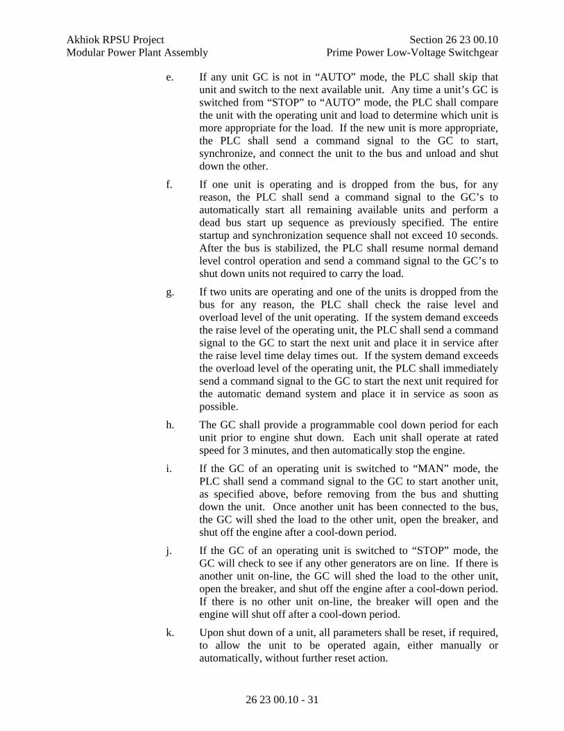
Akhiok RPSU Project Section 26 23 00.10 Modular Power Plant Assembly Prime Power Low-Voltage Switchgear
26 23 00.10 - 31
e. If any unit GC is not in “AUTO” mode, the PLC shall skip that unit and switch to the next available unit. Any time a unit’s GC is switched from “STOP” to “AUTO” mode, the PLC shall compare the unit with the operating unit and load to determine which unit is more appropriate for the load. If the new unit is more appropriate, the PLC shall send a command signal to the GC to start, synchronize, and connect the unit to the bus and unload and shut down the other.
f. If one unit is operating and is dropped from the bus, for any reason, the PLC shall send a command signal to the GC’s to automatically start all remaining available units and perform a dead bus start up sequence as previously specified. The entire startup and synchronization sequence shall not exceed 10 seconds. After the bus is stabilized, the PLC shall resume normal demand level control operation and send a command signal to the GC’s to shut down units not required to carry the load.
g. If two units are operating and one of the units is dropped from the bus for any reason, the PLC shall check the raise level and overload level of the unit operating. If the system demand exceeds the raise level of the operating unit, the PLC shall send a command signal to the GC to start the next unit and place it in service after the raise level time delay times out. If the system demand exceeds the overload level of the operating unit, the PLC shall immediately send a command signal to the GC to start the next unit required for the automatic demand system and place it in service as soon as possible.
h. The GC shall provide a programmable cool down period for each unit prior to engine shut down. Each unit shall operate at rated speed for 3 minutes, and then automatically stop the engine.
i. If the GC of an operating unit is switched to “MAN” mode, the PLC shall send a command signal to the GC to start another unit, as specified above, before removing from the bus and shutting down the unit. Once another unit has been connected to the bus, the GC will shed the load to the other unit, open the breaker, and shut off the engine after a cool-down period.
j. If the GC of an operating unit is switched to “STOP” mode, the GC will check to see if any other generators are on line. If there is another unit on-line, the GC will shed the load to the other unit, open the breaker, and shut off the engine after a cool-down period. If there is no other unit on-line, the breaker will open and the engine will shut off after a cool-down period.
k. Upon shut down of a unit, all parameters shall be reset, if required, to allow the unit to be operated again, either manually or automatically, without further reset action.

Akhiok RPSU Project Section 26 23 00.10 Modular Power Plant Assembly Prime Power Low-Voltage Switchgear
26 23 00.10 - 32
2. If the Master Control Switch is switched from the “AUTO” position to the “MAN ISOCH” position while units are operating in automatic mode, the system shall continue to operate in the present state. If the master selector switch is moved back to the “AUTO” position, the PLC shall revert back to operation in the automatic demand mode.
3. Demand Control: The automatic Demand Control System shall provide 1 level of unit stopping control and 2 levels of starting control. The 2nd level of starting control is considered the “overload level”. Each level shall have a kW and timing preset. The “raise level” and “lower level” shall be used by the demand control system as the point at which the level change timing preset begins. The timing preset is the time that the kW load is above a “raise level” or below a “lower level” set point, before the demand level changes. The Demand Control System shall have multiple demand levels. The highest demand level will command all units to start and go on-line.
Demand Control Generator(s) On Line
On-line kW (Overload)
Level Increase
Level Decrease
Level 1 #2 or #3 65 55 ---
Level 2 #1 100 90 45
Level 3 #1 & #2 or #3 165 145 80
Level 4 All 230 --- 130
Note: Generator #2 and #3 are equal capacity and the operator must select the lead unit using the OIU. If the lead unit faults or fails to start, the Demand Control shall automatically select the other unit.
E. Manual Operating Conditions If the Master Control Switch is in the "MAN ISOCH" position each generator GC shall control the respective generator in isochronous mode. The GC must be placed in MAN mode to start, stop, and control the generator. All functions shall be manually executed through the GC. If multiple generators are placed on line the GC’s shall proportionally share load.
F. Engine and Generation Alarm Conditions and Sequences. Note that these apply to both Auto and Manual operation.
1. Provide the following types of alarm sequences for each condition listed below:
a. Type 1 (Engine Alarm Soft Shutdown):
Upon alarm condition bring another generator on line, unload the first generator, open the circuit breaker, run through a cool down cycle, shut down engine, and illuminate “Alarm/Lockout” light and associated alarm annunciation light. Alarm light shall remain illuminated until the problem is corrected and the GC is manually
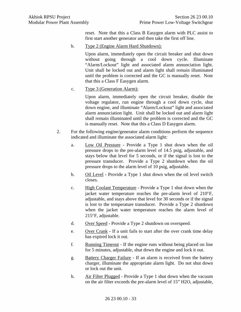
Akhiok RPSU Project Section 26 23 00.10 Modular Power Plant Assembly Prime Power Low-Voltage Switchgear
26 23 00.10 - 33
reset. Note that this a Class B Easygen alarm with PLC assist to first start another generator and then take the first off line.
b. Type 2 (Engine Alarm Hard Shutdown):
Upon alarm, immediately open the circuit breaker and shut down without going through a cool down cycle. Illuminate “Alarm/Lockout” light and associated alarm annunciation light. Unit shall be locked out and alarm light shall remain illuminated until the problem is corrected and the GC is manually reset. Note that this a Class F Easygen alarm.
c. Type 3 (Generation Alarm):
Upon alarm, immediately open the circuit breaker, disable the voltage regulator, run engine through a cool down cycle, shut down engine, and illuminate “Alarm/Lockout” light and associated alarm annunciation light. Unit shall be locked out and alarm light shall remain illuminated until the problem is corrected and the GC is manually reset. Note that this a Class D Easygen alarm.
2. For the following engine/generator alarm conditions perform the sequence indicated and illuminate the associated alarm light:
a. Low Oil Pressure - Provide a Type 1 shut down when the oil pressure drops to the pre-alarm level of 14.5 psig, adjustable, and stays below that level for 5 seconds, or if the signal is lost to the pressure transducer. Provide a Type 2 shutdown when the oil pressure drops to the alarm level of 10 psig, adjustable.
b. Oil Level - Provide a Type 1 shut down when the oil level switch closes.
c. High Coolant Temperature - Provide a Type 1 shut down when the jacket water temperature reaches the pre-alarm level of 210F, adjustable, and stays above that level for 30 seconds or if the signal is lost to the temperature transducer. Provide a Type 2 shutdown when the jacket water temperature reaches the alarm level of 215F, adjustable.
d. Over Speed - Provide a Type 2 shutdown on overspeed.
e. Over Crank - If a unit fails to start after the over crank time delay has expired lock it out.
f. Running Timeout - If the engine runs without being placed on line for 5 minutes, adjustable, shut down the engine and lock it out.
g. Battery Charger Failure - If an alarm is received from the battery charger, illuminate the appropriate alarm light. Do not shut down or lock out the unit.
h. Air Filter Plugged - Provide a Type 1 shut down when the vacuum on the air filter exceeds the pre-alarm level of 15” H2O, adjustable,
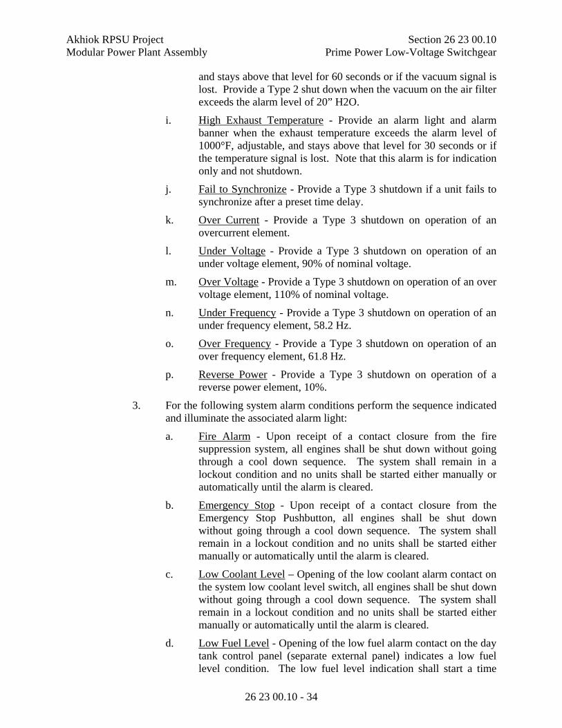
Akhiok RPSU Project Section 26 23 00.10 Modular Power Plant Assembly Prime Power Low-Voltage Switchgear
26 23 00.10 - 34
and stays above that level for 60 seconds or if the vacuum signal is lost. Provide a Type 2 shut down when the vacuum on the air filter exceeds the alarm level of 20” H2O.
i. High Exhaust Temperature - Provide an alarm light and alarm banner when the exhaust temperature exceeds the alarm level of 1000°F, adjustable, and stays above that level for 30 seconds or if the temperature signal is lost. Note that this alarm is for indication only and not shutdown.
j. Fail to Synchronize - Provide a Type 3 shutdown if a unit fails to synchronize after a preset time delay.
k. Over Current - Provide a Type 3 shutdown on operation of an overcurrent element.
l. Under Voltage - Provide a Type 3 shutdown on operation of an under voltage element, 90% of nominal voltage.
m. Over Voltage - Provide a Type 3 shutdown on operation of an over voltage element, 110% of nominal voltage.
n. Under Frequency - Provide a Type 3 shutdown on operation of an under frequency element, 58.2 Hz.
o. Over Frequency - Provide a Type 3 shutdown on operation of an over frequency element, 61.8 Hz.
p. Reverse Power - Provide a Type 3 shutdown on operation of a reverse power element, 10%.
3. For the following system alarm conditions perform the sequence indicated and illuminate the associated alarm light:
a. Fire Alarm - Upon receipt of a contact closure from the fire suppression system, all engines shall be shut down without going through a cool down sequence. The system shall remain in a lockout condition and no units shall be started either manually or automatically until the alarm is cleared.
b. Emergency Stop - Upon receipt of a contact closure from the Emergency Stop Pushbutton, all engines shall be shut down without going through a cool down sequence. The system shall remain in a lockout condition and no units shall be started either manually or automatically until the alarm is cleared.
c. Low Coolant Level – Opening of the low coolant alarm contact on the system low coolant level switch, all engines shall be shut down without going through a cool down sequence. The system shall remain in a lockout condition and no units shall be started either manually or automatically until the alarm is cleared.
d. Low Fuel Level - Opening of the low fuel alarm contact on the day tank control panel (separate external panel) indicates a low fuel level condition. The low fuel level indication shall start a time

Akhiok RPSU Project Section 26 23 00.10 Modular Power Plant Assembly Prime Power Low-Voltage Switchgear
26 23 00.10 - 35
delay relay, 2 hours, adjustable, and illuminate the alarm lamp. If the fuel level has not been corrected by the end of the timed interval all engines shall go through a Type 1 shutdown and the alarm lamp shall remain illuminated. The manual alarm reset button on the front of the switchgear master section will reset the timer relay for another interval and place the engines back in service if timed out. The reset function shall work any time during or after expiration of the timed interval.
e. PLC Failure - Upon failure of the PLC the alarm light shall remain illuminated until the PLC is back in acceptable service.
f. System Not In Auto – When the Master Control Switch (MCS) is changed from Auto to Manual the alarm lamp shall illuminate. The alarm lamp shall remain illuminated until the MCS is switched back to Auto.
g. Station Service Breaker Trip - Operation of any overcurrent element in the station service breaker trip unit shall immediately trip the circuit breaker.
h. Station Service Breaker Open – Any time the station service circuit breaker is open (trip or manually opened) the alarm lamp shall illuminate.
i. VFD Branch Breaker Trip - Operation of any overcurrent element in the VFD branch breaker trip unit shall immediately trip the circuit breaker.
j. VFD Branch Breaker Open – Any time the VFD branch circuit breaker is open (trip or manually opened) the alarm lamp shall illuminate.
k. Feeder Breaker Trip - Operation of the trip contact on the feeder breaker trip unit shall immediately trip the feeder circuit breaker, see Feeder Breaker Sequence below. On systems with more than one feeder breaker provide identical trip function for each.
l. Feeder Breaker Fail to Close – Any time the feeder breaker does not close upon a command to close (after a preset time delay) the alarm lamp shall illuminate. On systems with more than one feeder breaker provide alarm annunciation for each.
2.30 FEEDER BREAKER SEQUENCE OF OPERATION
A. Automatic Operation - When the Master Control selector switch is in the “AUTO” position the feeder breaker shall operate under control of the PLC. The feeder breaker can be opened at any time by rotating the breaker control knob to the OPEN position. The PLC shall then perform a dead bus start sequence (start all available generators) and re-close the breaker(s) after the pre-set time delay.
B. Manual Operation - When the Master Control selector switch is in the “MAN ISOCH” position and the bus is energized, the feeder breaker will operate under
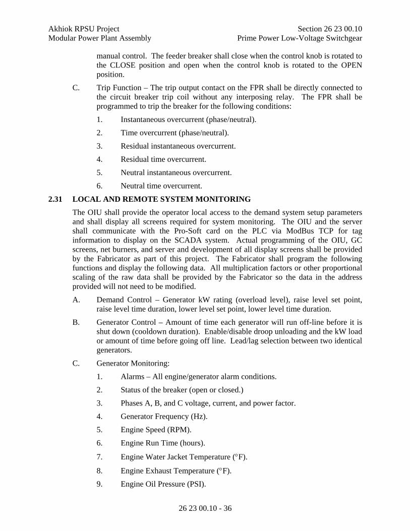
Akhiok RPSU Project Section 26 23 00.10 Modular Power Plant Assembly Prime Power Low-Voltage Switchgear
26 23 00.10 - 36
manual control. The feeder breaker shall close when the control knob is rotated to the CLOSE position and open when the control knob is rotated to the OPEN position.
C. Trip Function – The trip output contact on the FPR shall be directly connected to the circuit breaker trip coil without any interposing relay. The FPR shall be programmed to trip the breaker for the following conditions:
1. Instantaneous overcurrent (phase/neutral).
2. Time overcurrent (phase/neutral).
3. Residual instantaneous overcurrent.
4. Residual time overcurrent.
5. Neutral instantaneous overcurrent.
6. Neutral time overcurrent.
2.31 LOCAL AND REMOTE SYSTEM MONITORING
The OIU shall provide the operator local access to the demand system setup parameters and shall display all screens required for system monitoring. The OIU and the server shall communicate with the Pro-Soft card on the PLC via ModBus TCP for tag information to display on the SCADA system. Actual programming of the OIU, GC screens, net burners, and server and development of all display screens shall be provided by the Fabricator as part of this project. The Fabricator shall program the following functions and display the following data. All multiplication factors or other proportional scaling of the raw data shall be provided by the Fabricator so the data in the address provided will not need to be modified.
A. Demand Control – Generator kW rating (overload level), raise level set point, raise level time duration, lower level set point, lower level time duration.
B. Generator Control – Amount of time each generator will run off-line before it is shut down (cooldown duration). Enable/disable droop unloading and the kW load or amount of time before going off line. Lead/lag selection between two identical generators.
C. Generator Monitoring:
1. Alarms – All engine/generator alarm conditions.
2. Status of the breaker (open or closed.)
3. Phases A, B, and C voltage, current, and power factor.
4. Generator Frequency (Hz).
5. Engine Speed (RPM).
6. Engine Run Time (hours).
7. Engine Water Jacket Temperature (F).
8. Engine Exhaust Temperature (F).
9. Engine Oil Pressure (PSI).

Akhiok RPSU Project Section 26 23 00.10 Modular Power Plant Assembly Prime Power Low-Voltage Switchgear
26 23 00.10 - 37
10. Engine Air Cleaner Vacuum (in-H2O).
11. Engine Fuel Flow Rate (GPH).
12. Engine Total Fuel Use (Gal).
13. Engine CAN Bus – All available data from Engine Control Unit (ECU).
D. Bus Power Monitoring:
1. Phases A, B, and C voltage, current, and power factor for bus.
2. Metering – All available data from totalizing meter.
3. Phases A, B, and C voltage, current, and power factor for station service.
4. Metering – All available data from station service meter.
E. Feeder Circuit Breaker Monitoring:
1. Position indication for the feeder breaker.
2. All available data from the FPR.
F. Device Net Status.
G. Fuel system net burner to pull data from Tank Level Monitor and convert to Modbus TCP. SCADA net burner to pull data from PLC Pro-Soft and convert for use by SCADA and also to log and store alarms.
H. Plant total fuel use.
I. VFD Monitoring – All data available from Ethernet and/or ModBus connection on each of the variable frequency drives, quantity as indicated on the communication diagram on the project design drawings.
J. Engine Coolant Monitoring
1. Low engine coolant level alarm.
2. Engine coolant level (%).
3. Engine coolant return temperature (F).
K. Heat Recovery Monitoring
1. Alarms.
2. Heat recovery supply temperature (F) and return temperature (F).
3. Heat recovery pressure (PSI).
4. Heat recovery flow rate (GPM).
5. Heat output (BTU/hour).
6. Total heat delivered (100,000 BTU).
Akhiok RPSU Project Section 26 23 00.10 Modular Power Plant Assembly Prime Power Low-Voltage Switchgear
26 23 00.10 - 38
PART 3 - EXECUTION
3.1 FACTORY TESTS
A. Prior to shipment, the Low-Voltage Switchgear Fabricator shall perform factory tests at the shop where the switchgear is assembled. Provide certified copies of all manufacturers’ test data and results. Supply sufficient notice to the Authority prior to performing tests. The Authority reserves the right to witness all tests. Test procedures shall conform to ASME, IEEE, and ANSI standards, and NEMA standard practices section on testing, as appropriate and applicable.
B. The Fabricator shall provide all required equipment and measuring and indicating devices required to perform the tests indicated. All devices shall be certified correct or correction data furnished for the device.
C. Tests shall indicate satisfactory operation and attainment of guarantees and specified performance. Fabricator shall not ship equipment without approval by the Authority of the shop test reports.
D. If the Authority elects to witness the testing, prior to actual witness testing by the Authority, the Fabricator shall conduct sufficient tests and provide the test reports to the Authority to ensure that when the witness test is performed, the equipment will operate as specified.
E. At a minimum, provide the following operational tests:
1. Verify that the system performs the sequence of operations as specified. Verify that the equipment performs each task as specified.
2. Verify all protective relay functions for the FPR and GC.
3. Verify that the PLC starts and stops each generator based on the requirements of the demand table specified herein.
4. Verify that each annunciation point operates correctly. For external alarms, simulate the alarm.
5. Disconnect 120-volt AC power to the control power supply in the master unit to verify that the system continues to operate without interruption from the 24V DC source.
6. Test each variable frequency drive unit. Impress a 4-20 mA signal and verify the output of the VFD. Bench test completed unit. Provide a 3-phase motor of the size indicated and verify that the motor operates based on the 4-20 mA input signal.
F. FPR testing. Provide the following testing of the feeder protection relay.
1. After factory assembly and wiring of equipment, conduct functional tests to prove correct wiring and operation of equipment. The tests shall include but not limited to the following:
a. Input 3-phase AC signal voltage to all external terminal blocks where potential transformer connections shall be made. Verify with a voltmeter and phase angle meter that the correct voltage is present at all points indicated.

Akhiok RPSU Project Section 26 23 00.10 Modular Power Plant Assembly Prime Power Low-Voltage Switchgear
26 23 00.10 - 39
b. Input 3-phase AC signal current to all external terminal blocks where current transformer connections shall be made. Verify with an ammeter, current test plug, and phase angle meter, where possible, that the correct current is present at all points indicated. Currents through devices not provided with current test jacks may be verified with a clamp-on ammeter.
c. Operate each control switch and selector switch in all positions to verify that all control circuits operate as shown on the schematic diagrams.
d. Verify proper operation of all blocking, closing, and tripping contacts of the FPR.
e. Simulate remote contacts and switches by jumpers at the appropriate external terminal blocks to verify proper circuit operation.
f. Visually verify that all indicating lights operate properly.
2. The Fabricator shall calibrate and set all relays. Appropriate testing equipment shall be provided to test the relays as specified herein.
3. A report shall be provided in the System Operation & Maintenance Manual for all tests performed.
G. Perform the following tests on the electric boiler SCR panel.
At a minimum, provide the following operational tests:
1. Verify that the system performs the sequence of operations as described above. Verify that the equipment performs each task as specified.
2. Verify that each annunciation point operates correctly. For external alarms, simulate the alarm.
H. Perform the following electrical test and inspections of the switchgear:
The switchgear equipment and circuit breakers shall receive factory production tests as listed below:
1. Equipment.
a. Low frequency dielectric test.
b. Grounding of instrument cases.
c. Control wiring and device functional test.
d. Polarity verification.
e. Sequence test.
f. Low frequency withstand voltage test on major insulation components.
g. Low frequency withstand test on secondary control wiring.

Akhiok RPSU Project Section 26 23 00.10 Modular Power Plant Assembly Prime Power Low-Voltage Switchgear
26 23 00.10 - 40
2. Main Bus: Megger test at 1000 volts each bus to ground and phase-to-phase.
3. Contactors:
a. Coil check test.
b. Clearance and mechanical adjustment.
c. 300 Electrical and mechanical operation test.
d. Conductivity of current path test.
I. Tests that are provided by the manufacturer of the equipment need not be duplicated. However, documentation shall be provided that the test was performed.
J. Perform multiple repetitions of individual operations as required by the Authority to adequately demonstrate satisfactory operation of all functions.
3.2 SCADA SYSTEM TESTING
A. Prior to factory testing of the switchgear, the SCADA system shall be fully functional as specified in Section 26 23 00.50.
B. The switchgear control system shall be fully tested using the SCADA system as specified herein.
C. The OIU shall be fully functional and the switchgear shall be fully tested using the OIU. All alarm and control functions specified shall be available and indicated on the OIU.
D. The GC Screens shall be fully functional and the switchgear shall be fully tested using the GC Screens.
3.3 NOTIFICATION OF WITNESS TESTING
A The Authority shall have the right to inspect, at the factory, all equipment covered by these specifications any time during manufacture and assembly and to be present during any tests made on the equipment.
B The Authority may visit the manufacturing facility for final performance testing. The Fabricator shall make a technician available to the Authority to assist in the inspection and witness test of the switchgear. The technician shall instruct the Authority in all functions of the equipment.
C The Fabricator shall notify the Authority two weeks in advance of the scheduled test date. If the Fabricator ships the equipment without allowing the Authority to witness testing of the equipment, or before the Authority accepts the equipment test, the Authority reserves the right to have a third party test the equipment in Anchorage, Alaska or at the F.O.B. destination. All costs associated with a third party test shall be deducted from the Fabricator’s final payment. If the switchgear fails any test, the Fabricator shall be responsible for correction of all deficiencies, retesting, and proving the switchgear operates as specified and meets the requirements of these specifications with no increase in the contract price.
END OF SECTION

Akhiok RPSU Project Section 26 23 00.50 Modular Power Plant Assembly SCADA System for Prime Power Switchgear
26 23 00.50 - 1
SECTION 26 23 00.50
SCADA SYSTEM FOR PRIME POWER SWITCHGEAR
PART 1 - GENERAL
1.1 SCOPE
A. The Work included herein consists of providing a complete and operational Supervisory Control and Data Acquisition (SCADA) system, as specified herein, for the Utility included under this solicitation. The SCADA system shall be provided by an experienced programmer referred to as Developer herein.
B. The Developer shall develop the SCADA system and programming for the OIU and GC Interface Screens, switchgear data storage server, and remote and local PCs. The SCADA system shall include Supervisory and Trending application software, custom project software file(s), and other software and files required to make a complete and operational system.
C. The Developer shall provide all labor, equipment, incidentals and resources as specified and needed to furnish, install, calibrate, test, start-up and place in satisfactory operation a complete SCADA system for the Akhiok electric utility (Utility), as indicated herein.
D. The Authority and Utility shall maintain ownership and use of all custom project software files and documentation developed to meet the requirements of this solicitation. All SCADA Supervisory and Trending application software licenses provided under this solicitation shall include the legal right for the Authority and Utility to use the software for an indefinite period of time. The Authority and Utility shall have unlimited rights to install and operate the SCADA Supervisory and Trending application software, up to the number of software licenses issued, and to install, operate and modify the custom project files as needed for the benefit of the Utility, without the requirement to commit to on-going maintenance or service agreements.
E. The Developer shall fully test the SCADA system with the Prime Power Low-Voltage Switchgear and the generating equipment as specified herein and in Section 26 23 00.10 - Prime Power Low-Voltage Switchgear.
1.2 RELATED REQUIREMENTS
A. Section 26 05 00 Common Work Results for Electrical
B. Section 26 05 02 Basic Electrical Materials and Methods
C. Section 26 23 00.10 Prime Power Low-Voltage Switchgear
1.3 SUBMITTALS
A. Provide submittals in accordance with Section 26 05 00 Common Work Results for Electrical and Division 1.
Akhiok RPSU Project Section 26 23 00.50 Modular Power Plant Assembly SCADA System for Prime Power Switchgear
26 23 00.50 - 2
B. Submit data sheets and catalog data showing all supplied features, options and configurations of the SCADA Supervisory and Trending application software.
C. Submit screen shots of the proposed OIU and GC Interface Screen custom project file(s) for each Utility. Provide a Tag list and narrative operating description of the project file(s).
1.4 SCADA SYSTEM SOFTWARE
A. All SCADA Supervisory and Trending application software licenses and custom project files, as well as upgrades and maintenance described in the Warranty herein, shall be included in the Developer’s bid price. For the purposes of this solicitation the SCADA Supervisory application software is defined as:
Machine-readable object code used for the supervision, control and monitoring of the programmable logic controller (PLC) and other switchgear and field devices. The Supervisory application software interacts with custom project file(s) that are configured and customized for each Utility to display and control tags from the PLC and devices, as indicated in Section 26 23 00.10 - Prime Power Low-Voltage Switchgear.
For the purposes of this solicitation the SCADA Trending application software is defined as:
Software that provides the functions as described in Paragraph 2.2 - Trending
B. For the SCADA system to function both the Supervisory application software and custom project files shall be installed on a client computer.
C. The Authority and Utility shall be able to upgrade the Supervisory and Trending application software and to edit, modify, change, and manipulate the custom project files to fit their requirements.
D. The Authority shall own outright all other software and files developed under this solicitation by the Developer without license and shall have full rights to the files and programming code and may distribute, modify, or install it on any number of computers that may be owned by the Authority or other utilities the Authority may work with from time-to-time without additional costs or fees.
E. For the purposes of this contract “other software applications and files” shall include but may not be limited to:
Customized screens and parameters developed for use with the Supervisory and Trending application software. (i.e., custom project files)
Any other software and interfaces developed between the Supervisory and Trending application software, custom project files, and other application software and files related to collecting and reporting power plant data via the SCADA system.

Akhiok RPSU Project Section 26 23 00.50 Modular Power Plant Assembly SCADA System for Prime Power Switchgear
26 23 00.50 - 3
1.5 QUALITY ASSURANCE
A. The Developer is responsible for quality assurance and completion of all work identified in these specifications. All work shall be subject to evaluation and inspection by the Authority at all times to assure satisfactory progress, and to verify that work is being performed in accordance with the specifications.
B. The SCADA system shall be furnished by a single Developer who shall assume all responsibility for providing a complete and integrated SCADA system.
1.6 DEVELOPER QUALIFICATIONS
A. The SCADA system shall be the product of a Developer who can demonstrate at least five (5) years of continuous satisfactory experience in designing, implementing, furnishing and installing comparable SCADA systems for remote installations.
B. The Developer shall have a thorough working knowledge of remote, off-grid prime power electric power plant controls and operating practices.
C. A list of five prior projects that key staff have worked on may be requested by the Authority after the bid opening and prior to award in order to verify Developer qualifications. The list shall include installation date, description of installation, and a reference contact for each installation.
1.7 DEVELOPER WARRANTY
A. The Developer shall provide a warranty for the work for a period of not less than one-year after final acceptance of the SCADA system by the Authority. Any deficiencies identified in the programming, software, screen images, trending, or other features or aspects of the SCADA system, identified by either the Authority or the Utility, shall be promptly corrected by the Developer at no additional cost. The Developer shall assist the Authority as directed in determining causes of deficiency or failure.
B. In addition to the specified requirements for SCADA system programming, testing, commissioning, and warranty work, during the one-year warranty period the Developer shall provide an additional twelve (12) hours of programming assistance and technical support to modify the SCADA as requested by the Authority or the Utility. These hours are in addition to any technical requirements specified for programming, start-up and commissioning efforts, and shall be included in the Developer’s bid price. The programming assistance and technical support may be required to be provided at a single event or may be spread out over the year as directed by the Authority or the Utility, and will be performed at the Developer’s office and not at the location of the Utility.
1.8 OPERATION AND MAINTENANCE MANUALS
A. See Section 26 23 00.10 - Prime Power Low-Voltage Switchgear

Akhiok RPSU Project Section 26 23 00.50 Modular Power Plant Assembly SCADA System for Prime Power Switchgear
26 23 00.50 - 4
PART 2 - PRODUCTS
2.1 GENERAL
A. The Developer shall provide a fully functional SCADA system specified herein and to meet the requirements of Section 26 23 00.10 – Prime Power Low-Voltage Switchgear.
B. The SCADA system shall be compatible with the switchgear hardware.
C. The Supervisory system shall not be dependent on the switchgear data server, or any other server, for operation. It shall read information directly from the PLC, switchgear devices, and power plant LAN.
D. The Supervisory and Trending software may be separate and distinct programs.
E. Multiple applications of the SCADA system shall run concurrently. The OIU and GC interface screens, alarms, and monitoring points shall be identical for all SCADA applications, regardless if accessed locally or remotely via the internet. All devices in the power plant, and no less than six (6) additional remote or local devices, shall be authorized to run concurrently.
F. The SCADA system shall function on the power plant LAN without being dependent on connectivity to the internet.
G. The SCADA system shall not require or depend on external activation, internet or hardware.
H. The Supervisory and Trending application software and custom project file(s) shall be relatively small in size and have a simple installation routine. The SCADA system and software installation shall tolerate low throughput and high latency connections. Down to as low as 56kbs and 500ms delay without dropping. Pushing software across low quality communications links makes small files sizes necessary.
I. The SCADA system shall function on Microsoft Windows 7 through Windows 10 Professional.
J. The graphic interface shall be user friendly and have the capability without modification or setup to allow personnel with large fingers to use generic touch screens without a mouse or keyboard.
K. The Supervisory system shall start and stop engines, reset alarms, change demand levels and have a confirm action dialog box for critical functions, as well as maintain separate alarm logs for Type 1 and other alarms (refer to 3.3.H – Alarm History Screens).
L. The Developer shall maintain a secure FTP or web site with custom project files and other files to be readily downloaded and installed.
M. The Developer shall provide comments in the code for ease of future maintenance and changes.

Akhiok RPSU Project Section 26 23 00.50 Modular Power Plant Assembly SCADA System for Prime Power Switchgear
26 23 00.50 - 5
N. The SCADA system installation and setup shall be capable of being performed remotely via low bandwidth internet access.
O. Secure encryption shall be provided.
2.2 TRENDING
A. The Developer shall provide, configure, test and implement a historical database on the switchgear data storage server for historical data archiving, analysis, reporting, trending and system back-up of all data presented by the SCADA system. All historical data shall be fully synchronized and time-stamped, using a single time series (clock), so that historical data from all monitored devices may be compared to a single time series.
B. The SCADA system shall include features for the management of historical data. The SCADA system shall record historical values of analog variables on a periodic basis and values of digital variables on an event basis (change of state). The historical database must be capable of storing a minimum of one (1) year of historical data. All historical data shall be recorded on the switchgear data storage server. Historical files more than one (1) year old shall be automatically deleted.
C. Trending data shall be exportable from the historical database, and the section of the trend to be exported shall be selectable by clicking and dragging the mouse across the trend. Any portion of the historical database shall be exportable. Data shall be exported to CSV or TXT formatted files, or similar file system as approved by the Authority. Exported files shall be of a manageable size compatible with the internet requirements of Paragraph 2.1. Exported trend data shall be readily capable of being printed or plotted to Adobe pdf format or to a designated printer.
D. Refer to Paragraph 3.5, Trending Application Tags, for representative example of historical data to be archived and available for trending.
2.3 SECURITY
A. Password Protection. Provide the following access password protection:
1. Viewing only. In this level of access the viewer will be able to view the SCADA system but will not be able to modify any file or setpoint.
2. Administrator. In this level of access, the viewer will be able to change the demand levels and timers, change the lead generators, remote start and stop engines, and perform other functions as directed by the Authority.
B. The Developer shall provide a description of the SCADA system security encryption and authentication protocol for review and approval.

Akhiok RPSU Project Section 26 23 00.50 Modular Power Plant Assembly SCADA System for Prime Power Switchgear
26 23 00.50 - 6
PART 3 - EXECUTION
3.1 FACTORY TESTS
A. Prior to factory testing of the switchgear, the SCADA system shall be fully functional as specified in Section 26 23 00.10 - Prime Power Low-Voltage Switchgear.
B. The switchgear control system shall be fully tested using the SCADA system as specified herein.
C. The OIU shall be fully functional and the switchgear shall be fully tested using the OIU. All alarm, indication, and control functions specified shall be available and indicated on the OIU.
D. The GC Interface Screens shall be fully functional and the switchgear shall be fully tested using each generator section GC Interface Screen. All alarm, indication, and control functions specified shall be available and indicated on each GC Interface Screen.
E. The Trending application shall be fully functional and tested, and all Trending application functions fully operational, as indicated herein.
3.2 CUSTOMER TRAINING
A. The Developer shall provide a minimum of 8 hours of training for the Authority and Utility personnel. Training shall be provided separately for each Utility.
B. Training shall occur after substantial completion of the project using the actual power plant equipment. Coordinate with the Authority and Utility to ensure that the appropriate individuals are available.
C. During training, make modifications to the SCADA system programming as directed by the Authority to incorporate any system control modifications identified during testing, startup, or commissioning.
D. Training shall be provided using the manuals as specified herein.
3.3 OIU SCREEN IMAGES
The SCADA system screens shall display all data as specified in Section 26 23 00.10 - Prime Power Low-Voltage Switchgear. At a minimum, the Developer shall provide screens similar to the images shown in following paragraphs. The screen images are representative of the minimum data required and desired format. Each screen image shall be provided on the switchgear Operator Interface Unit (OIU), local PC’s connected to the LAN, and available via the remote SCADA system over the internet.
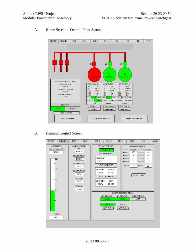
Akhiok RPSU Project Section 26 23 00.50 Modular Power Plant Assembly SCADA System for Prime Power Switchgear
26 23 00.50 - 7
A. Home Screen – Overall Plant Status:
B. Demand Control Screen:

Akhiok RPSU Project Section 26 23 00.50 Modular Power Plant Assembly SCADA System for Prime Power Switchgear
26 23 00.50 - 8
C. Bus Monitoring & Metering Screen:
D. Engine-Generator Screen (1 for each genset, 3 total):
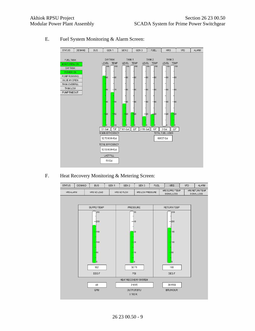
Akhiok RPSU Project Section 26 23 00.50 Modular Power Plant Assembly SCADA System for Prime Power Switchgear
26 23 00.50 - 9
E. Fuel System Monitoring & Alarm Screen:
F. Heat Recovery Monitoring & Metering Screen:

Akhiok RPSU Project Section 26 23 00.50 Modular Power Plant Assembly SCADA System for Prime Power Switchgear
26 23 00.50 - 10
G. Variable Frequency Drive (VFD) Monitoring Screen:
H. Alarm History Screens:
Provide two separate Alarm History Screens, one for Type 1 Soft Shutdown alarms and a second screen for Master Section, Type 2 and Type 3 Alarms. The Type 1 Alarm screen shall use alternating yellow and white lines, as indicated below. The second screen shall use alternating red and white lines.

Akhiok RPSU Project Section 26 23 00.50 Modular Power Plant Assembly SCADA System for Prime Power Switchgear
26 23 00.50 - 11
3.4 GC INTERFACE SCREEN IMAGES
At a minimum, the Developer shall provide the following screen images for each Utility provided under this contract. Each screen image shall be provided on the switchgear generator control panel interface screen. Note: the following Generator and Engine screen images are line graphs with time as the horizontal axis, and shall toggle between the 4-graph display to a single graph full screen display when a graph is touched.
A. Generator Screen:
B. Engine Screen:
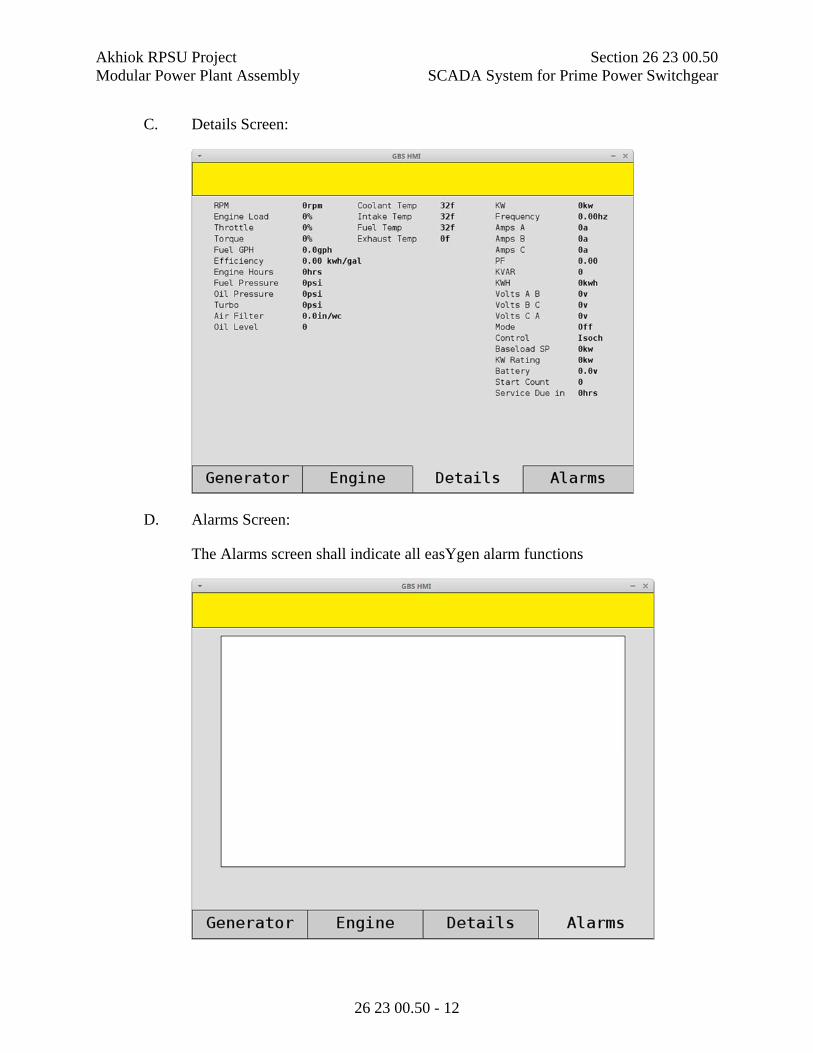
Akhiok RPSU Project Section 26 23 00.50 Modular Power Plant Assembly SCADA System for Prime Power Switchgear
26 23 00.50 - 12
C. Details Screen:
D. Alarms Screen:
The Alarms screen shall indicate all easYgen alarm functions

Akhiok RPSU Project Section 26 23 00.50 Modular Power Plant Assembly SCADA System for Prime Power Switchgear
26 23 00.50 - 13
3.5 TRENDING APPLICATION TAGS
The following Trending Export screens show a representative example of historical data to be archived and available for trending:

Akhiok RPSU Project Section 26 23 00.50 Modular Power Plant Assembly SCADA System for Prime Power Switchgear
26 23 00.50 - 14

Akhiok RPSU Project Section 26 23 00.50 Modular Power Plant Assembly SCADA System for Prime Power Switchgear
26 23 00.50 - 15
END OF SECTION

Akhiok RPSU Project Section 26 32 13 Modular Power Plant Assembly Engine Generators
26 32 13-1
SECTION 26 32 13 ENGINE GENERATORS
PART 1 - GENERAL
1.1 SCOPE
A. The Work included herein shall consist of providing, fabricating, and factory testing complete engine generator units as specified herein.
B. Each unit shall be harmonically balanced and shall be delivered complete and ready for installation.
C. Provide all accessories as specified for all engine generator units plus any additional components listed.
1.2 RELATED REQUIREMENTS
A. Division 23 Mechanical
B. Section 26 05 00 Common Work Results for Electrical
C. Section 26 05 02 Basic Electrical Materials and Methods
D. Section 26 05 33 Raceway and Boxes for Electrical Systems
1.3 SUBMITTALS
A. Provide in accordance with Section 26 05 00 Common Work Results for Electrical and Division 1.
B. Provide complete and accurate drawings of the equipment, including outline drawings and dimensional data which fully describe the height, width, and depth of the equipment; skid construction; schematics; wiring diagrams; and other relevant details.
C. Provide mechanical and electrical performance data including intake and exhaust air flow; charge air cooling requirements (if applicable); heat rejection; engine coolant pump curve at rated speed; fuel flow rate; fuel consumption at 100%, 75%, 50%, and 25% of rated prime power; and other relevant data.
D. Provide manufacturer’s catalog literature for all accessories and equipment.
E. A torsional vibration analysis (TVA) shall be provided for each proposed engine generator combination within 14-days of contract award.
1.4 REGULATORY COMPLIANCE
The Environmental Protection Agency (EPA) has issued New Source Performance Standards (NSPS) regulations governing use of stationary diesel engines in remote areas of Alaska. The following provision of 40 CFR Subpart IIII applies to this solicitation:
A. On November 13, 2019, 40 CFR 60.4216 (c) was revised as follows: Manufacturers, owners, and operators of stationary CI ICE that are located in remote areas of Alaska may choose to meet the applicable emission standards for emergency engines in §§ 60.4202 and 60.4205, and not those for non-emergency engines in §§ 60.4201 and 60.4204, except that for 2014 model year and later nonemergency CI ICE, the owner or operator of any such engine

Akhiok RPSU Project Section 26 32 13 Modular Power Plant Assembly Engine Generators
26 32 13-2
must have that engine certified as meeting at least the Tier 3 PM standards in 40 CFR 89.112 or 40 CFR 1042.101.
In order to comply with EPA emissions requirements and also be compatible with the intended service applications, the diesel engine furnished under this solicitation shall be a new Tier 3 Marine certified engine.
1.5 QUALITY ASSURANCE
A. All equipment shall be designed, fabricated, and assembled in accordance with recognized and acceptable engineering and shop practices. Individual parts shall be manufactured to standard sizes and gauges so that repair parts, furnished at any time, can be installed in the field. Like parts of duplicate units shall be interchangeable. Except where specific allowance is made in this specification for rebuilt or remanufactured engines, Equipment shall not have been in service at any time prior to delivery, except as required by tests.
B. Equipment and components furnished under these specifications shall be in accordance with the requirements of applicable UL, NEC, IEEE, NEMA, and ANSI standards.
1.6 FABRICATOR QUALIFICATIONS
The engine generators shall be furnished, assembled, and tested by a qualified fabricator (Fabricator) who is regularly engaged in the business of providing diesel engine driven generator equipment.
A. The Fabricator must have staff with extensive experience in packaging diesel engine driven electrical generators. A list of five successful installations that key staff have worked on may be requested by the Authority after the bid opening and prior to award in order to verify Fabricator qualifications. The list must include installation date, description of installation, and a reference contact for each installation.
B. The Fabricator must maintain a competent service organization that is available for field service calls. A description of the organization including resumes of key personnel may be requested by the Authority after the bid opening and prior to award in order to verify Fabricator qualifications.
C. The Fabricator must have a fabrication facility with adequate space and appropriate equipment as required to perform the work. The Authority may inspect the Fabricator’s shop after the bid opening and prior to award in order to verify Fabricator qualifications.
1.7 CONTRACTOR WARRANTIES
A. The Contractor shall warrant the work for a period of not less than one-year after energization of the equipment or 18 months after delivery to the F.O.B. point, whichever comes first. In the event of equipment or component failure during the warranty period, the Contractor shall replace such defective equipment or components and bear all associated costs. Costs shall include material, parts, and labor. The Contractor will be allowed to charge for travel and per diem expenses related to warranty service at actual cost plus 10%. The Contractor shall pursue

Akhiok RPSU Project Section 26 32 13 Modular Power Plant Assembly Engine Generators
26 32 13-3
manufacturer's warranties to the extent necessary to obtain replacement equipment and provide proof of action taken upon request. Assist the Authority as directed in determining cause of failure.
B. The warranty shall state in clear terms exactly what warranty coverage the seller provides, for each unit and attachments. This shall include the terms, length of coverage, reporting responsibilities, how the warranty applies to accessory equipment, restrictions, locations of local facilities for handling warranty and other repairs (including contact names), and any other available information pertaining to warranty.
C. Provide a nametag on each piece of equipment that clearly identifies the party responsible for the warranty. Nametag shall include the name, address, and phone number, and shop order or Contractor’s serial number.
1.8 OPERATION AND MAINTENANCE MANUALS.
A. Provide one (1) complete bound set of operation and maintenance (O&M) manuals for each unique engine generator unit. Identification symbols for all replaceable parts and assemblies shall be included. Provide manuals for the following equipment:
1. Engine. 2. Generator. 3. Voltage Regulator. 4. All accessories.
B. For each engine provide all available factory service publications including parts manuals, service manuals, component technical manuals, etc.
C. For all other components of each engine generator unit provide:
1. Equipment function, normal operating characteristics, and limiting conditions.
2. Assembly, installation, alignment, adjustment, and checking instructions. 3. Operating instructions for start-up, routine and normal operation, regulation
and control, shutdown, and emergency conditions. 4. Lubrication and maintenance instructions. 5. Guide to "troubleshooting." 6. Parts list and predicted life of parts subject to wear. 7. Outline, cross section, elevation, and assembly drawings 8. Engineering data including all mechanical and electrical performance
characteristics. 9. Complete AC connection and three-line diagrams. 10. Complete DC schematics including voltage regulator, fuel injector pump,
sensors, switches, fuses, and all other devices.
D. The operation and maintenance manuals shall be in addition to any instructions or parts list packed with or attached to the equipment when delivered, or any information submitted for review.
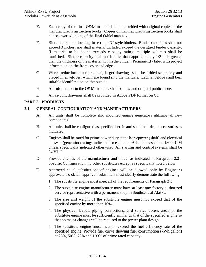
Akhiok RPSU Project Section 26 32 13 Modular Power Plant Assembly Engine Generators
26 32 13-4
E. Each copy of the final O&M manual shall be provided with original copies of the manufacturer’s instruction books. Copies of manufacturer’s instruction books shall not be inserted in any of the final O&M manuals.
F. Bind materials in locking three ring “D” style binders. Binder capacities shall not exceed 3 inches, nor shall material included exceed the designed binder capacity. If material to be bound exceeds capacity rating, multiple volumes shall be furnished. Binder capacity shall not be less than approximately 1/2 inch greater than the thickness of the material within the binder. Permanently label with project information on the front cover and edge.
G. Where reduction is not practical, larger drawings shall be folded separately and placed in envelopes, which are bound into the manuals. Each envelope shall bear suitable identification on the outside.
H. All information in the O&M manuals shall be new and original publications.
I. All as-built drawings shall be provided in Adobe PDF format on CD.
PART 2 - PRODUCTS
2.1 GENERAL CONFIGURATION AND MANUFACTURERS
A. All units shall be complete skid mounted engine generators utilizing all new components.
B. All units shall be configured as specified herein and shall include all accessories as indicated.
C. Engines shall be rated for prime power duty at the horsepower (shaft) and electrical kilowatt (generator) ratings indicated for each unit. All engines shall be 1800 RPM unless specifically indicated otherwise. All starting and control systems shall be 24 VDC.
D. Provide engines of the manufacturer and model as indicated in Paragraph 2.2 - Specific Configuration, no other substitutes except as specifically noted below.
E. Approved equal substitutions of engines will be allowed only by Engineer's approval. To obtain approval, submittals must clearly demonstrate the following:
1. The substitute engine must meet all of the requirements of Paragraph 2.3
2. The substitute engine manufacturer must have at least one factory authorized service representative with a permanent shop in Southcentral Alaska.
3. The size and weight of the substitute engine must not exceed that of the specified engine by more than 10%.
4. The physical layout, piping connections, and service access areas of the substitute engine must be sufficiently similar to that of the specified engine so that no major changes will be required to the power plant design.
5. The substitute engine must meet or exceed the fuel efficiency rate of the specified engine. Provide fuel curve showing fuel consumption (kWh/gallon) at 25%, 50%, 75% and 100% of prime rated capacity.

Akhiok RPSU Project Section 26 32 13 Modular Power Plant Assembly Engine Generators
26 32 13-5
6. The substitute engine must be provided with a single jacket water cooling circuit without a separate aftercooler circuit.
7. The substitute engine must meet or exceed the heat rejection to the jacket water circuit of the specified engine.
8. The engine must not be equipped, or require to be equipped, with any exhaust emissions equipment including Exhaust Gas Recirculation, Diesel Oxidation Catalyst, Diesel Particulate Filter, or Selective Catalytic Reduction.
F. Provide Newage/Stamford generators as indicated in the Specific Configuration requirements that follow or Kato equal, no other substitutes except as specifically noted below. The generator shall be rated for continuous output at the value and temperature rise indicated at 0.8 power factor. The generator shall be 2/3 pitch winding, 3 phase, 277/480 volt, 12 lead reconnectable, with PMG excitation.
G. If a Marathon or other generator of equivalent or greater capacity is provided it shall be modified and upgraded prior to installation. Upon receipt of the generator from the factory it shall be taken to a manufacturer’s authorized warranty service shop and the following tasks shall be performed:
1. Remove rotor assembly, bearing, exciter, diode plate and inspect for defects.
2. If any defects are encountered immediately file a warranty claim with the manufacturer.
3. Electrically test all windings.
4. Encapsulate exciter rotor winding with epoxy.
5. Replace bearing prior to reinstalling exciter. Bearing shall meet the minimum requirements of these specifications.
6. Replace diode plate mounting bolts with grade 8 bolts and use Loctite.
7. Insulate main rotor leads with phase paper. Secure leads with heat shrinkable polyester tape using epoxy on all knots.
8. Spray coat all windings with epoxy.
9. Dynamically balance and re-assemble.
10. Test at rated RPM.
2.2 SPECIFIC CONFIGURATION
Furnish Engine Generators of the capacity and configuration listed below:
No. 1: Engine - 148 hp, 100 ekW prime, John Deere 4045AFM85, Tier 3 Marine. Starting and Control Voltage = 24 VDC (convert as required). Generator - Minimum 125kW continuous at 105°C rise, Newage/Stamford UCI274E or Kato equal.
No. 2: Engine - 148 hp, 100 ekW prime, John Deere 4045AFM85, Tier 3 Marine. Starting and Control Voltage = 24 VDC (convert as required). Generator - Minimum 125kW continuous at 105°C rise, Newage/Stamford UCI274E or Kato equal.

Akhiok RPSU Project Section 26 32 13 Modular Power Plant Assembly Engine Generators
26 32 13-6
No. 3: Engine - 99 hp, 65 ekW prime, John Deere 4045TFM85, Tier 3 Marine. Starting and Control Voltage = 24 VDC (convert as required). Generator - Minimum 90kW continuous at 105°C rise, Newage/Stamford UCI274C or Kato equal.
2.3 ENGINE
A. Provide a skid mounted, 1800 RPM, diesel engine complete with generator/alternator and ready for service. The unit shall be of newest design and of recent manufacture.
B. Marine engines shall be furnished without a charging alternator, heat exchanger, coolant expansion tank, or accessory reduction gear drive. Factory installed components shall be removed as required.
C. The engine shall be a four-cycle, water-cooled, direct injection diesel engine of 4 or 6 cylinder in-line configuration as indicated by model number and shall be provided with a gear driven coolant pump where offered by manufacturer.
D. Cylinder Liners: The engines shall be provided with removable cylinder liners to facilitate field rebuilding.
E. Horsepower: Certified engine power curves and fuel consumption at 25%, 50%, 75%, and 100% loading, shall be submitted showing the manufacturer's approval of the engine rating for engine generator prime power application. Special ratings or "continuous standby" ratings will not be acceptable.
F. Engine Control: All engine control functions will be performed by remote switchgear which will perform all start/stop, speed, paralleling, and load sharing control functions in addition to all engine function monitoring and safety shut downs. Engine manufacturer’s electronic control panels shall not be provided.
G. ECU and Isochronous Governor: Provide an Engine Control Unit (ECU) for interface with the switchgear. Program the ECU for nominal 1800 RPM operation at 2.5 VDC input, variable RPM above and below 2.5 VDC input, and idle operation at input less than or equal to 0.5 VDC.
H. ECU Mounting: When available from the engine manufacturer, provide an ECU mounting panel for installation of the ECU and accessories. Mount in a readily accessible location on the engine or on the generator enclosure. Provide service loops in wiring harnesses as required.
I. Fuel: The engine shall be capable of satisfactory performance on No. 1 or No. 2 Ultra Low Sulphur Diesel (ULSD) Fuel.
J. Fuel System: The engine shall have manufacturer’s engine mounted fuel filters with replaceable elements. Fuel supply and return lines shall be routed to the front of generator skid for field connection to the plant piping. See Drawings for detailed configuration.
K. Lubrication: The engine shall have a gear type lubricating oil pump for supplying oil under pressure to the main bearings, crankshaft bearings, pistons, piston pins, timing gears, camshaft bearings and valve rocker mechanism. Threaded spin-on type, full flow lubricating oil filters shall be provided. The oil drain line shall be
Akhiok RPSU Project Section 26 32 13 Modular Power Plant Assembly Engine Generators
26 32 13-7
connected to the front of generator skid for field connection to the plant piping. See Drawings for detailed configuration.
L. Oil Level: The engine shall have a combination visual oil level site gauge with adjustable high and low level switches, Murphy L129CK1 or approved equal. Mount on rubber isolators and connect to engine with minimum #8 hoses. Carefully route upper vent hose to avoid any low point traps and connect directly into crankcase. Route lower hose to a connection directly on the oil pan. Do not tee lower hose into oil drain line. See Drawings for installation detail.
M. Fuel and Oil Hoses: All hoses for fuel, lube oil, vents, mechanical gauges, etc., shall be Aeroquip type FC300, Eaton Weatherhead H569 or approved equal. Minimum hose size shall be 5/16” (#6). Provide with re-useable JIC swivel type fittings. Push-on or barb type hose connections will not be allowed. Route hoses to avoid wear points and to ensure access to normal service points on the engine. Securely support hoses from engine and skid.
N. Glycol Hoses: All hoses for glycol shall be Teflon hose with stainless steel outer braid, Eaton Weatherhead H243 or approved equal. Provide with re-useable plated steel straight JIC swivel ends with NPT adapters. Route hoses to avoid wear points and to ensure access to normal service points on the engine. Securely support hoses from engine and skid.
O. Wire Loom: All wiring for control and instrumentation shall be routed in plastic loom. Provide tee fittings for all branch connections. Route loom to avoid wear points and to ensure access to normal service points on the engine. Securely support loom from engine and skid.
P. Protective Guards: All moving parts and hot surfaces shall be provided with protective guards in accordance with U.L Standard 2200.
Q. Air Cleaners: The engine shall be provided with a dry-type, replaceable element air cleaner with a metal canister, Donaldson or approved equal. Open disposable type air filters or plastic canisters will not be accepted. Provide visual air restriction indicator, 20” water column limit, manual reset, Donaldson X002251 or approved equal.
R. Starting: The engine shall be equipped with a 24 VDC electric starting system as indicated in Paragraph 2.2 - Specific Configuration. The starting system shall be of sufficient capacity to crank the engine at a speed which will allow full diesel starting. A starter auxiliary relay shall be remote mounted in control wiring junction box, Caterpillar 9X-8124 or approved equal.
S. Control Power: To provide 24VDC power to the control wiring junction box, a 30A circuit breaker with switch shall be mounted on the engine in the vicinity of the starter, Cooper 187-030-F-00 or approved equal.
T. Sensors and Safety Controls: The engine shall be equipped with the following:
1. Exhaust Gas Temperature. High temperature (650°C) 2 wire 100 ohm RTD with 2’ high temperature lead wire, spring strain relief, Deutz DT06-2S-E008 male connector, Deutz DT04-2P-E008 female connector, and

Akhiok RPSU Project Section 26 32 13 Modular Power Plant Assembly Engine Generators
26 32 13-8
compression fitting with 1/4” MPT adapter. Eustis RGB7B203B02X0 with NS44 adapter or approved equal. See note 2 below.
2. Air Filter Vacuum Sensor. 4-20mA, -30”Hg to 0 PSIG, 1/4” MPT. Noshok 100-30V-1-1-2-7 or approved equal.
Note 1. The above listed sensors shall be independent from engine gauges and all other devices and sensors. Where standard factory furnished sensors for the above listed functions are required for operation of the ECU, provide additional duplicate sensors as specified. All sensors shall be installed on the engine and wired to terminal blocks as indicated in the Drawings.
Note 2. Upon completion of shop testing, if exhaust gas temperature sensor is installed in flex remove sensor and tywrap to engine in a secure location for shipping.
U. Safety Controls: The automatic switchgear provided by others shall be equipped with automatic safety controls which will shut down the engine in the event of high jacket water temperature (primary), high lubricating oil temperature, low lubricating oil pressure, high or low lubricating oil level, high air filter restriction, and engine overspeed based on J1939 CANbus and engine mounted sensors. Note that a single low water shut down switch will be installed on the external cooling system.
2.4 EXHAUST FLEX
A. A flexible, continuous, 18 inch long stainless steel exhaust flex connector with welded connections shall be furnished for each engine, Alaska Rubber or approved equal. Provide an appropriate engine mating connection at one end and an ASA 125 lb. flange sized to match silencer at the opposite end. Slotted cuff connections are not acceptable. Provide gasket, bolts, v-clamp, or any other components required for connection to the engine. Provide a 90° elbow where required for the flex to be installed vertically. Note that if the exhaust temperature sensor cannot be installed directly in the outlet connection, a 1/4” FPT stainless steel thread-o-let shall be welded into the flex between the engine connection and the corrugated hose.
2.5 ACCESSORIES
Provide the following accessories for each generating unit (unless otherwise indicated):
A. Spring vibration isolators complete with mounting hardware, four (4) per each unit, sized for the complete engine generator unit weight. Caldyn Type RJ or approved equal.
B. Drip pan, 16-gauge galvanized sheet metal, liquid tight joints, 20” wide by 50” long by 1” high.
C. Provide minimum 800 cold crank amp 12-volt starting batteries, two for each engine. Batteries shall be sealed maintenance free, Optima Red Top NAPA Part Number BAT N993478RED or approved equal. Furnish and install battery racks sized to hold the batteries with hardware to secure the battery for shipping.

Akhiok RPSU Project Section 26 32 13 Modular Power Plant Assembly Engine Generators
26 32 13-9
D. Each engine shall be provided with two each #2/0 AWG arctic flex battery cables, length as required, plus one each #2/0 AWG by 12-inch long jumper. All cables shall include compression type terminal ends shipped loose. One battery cable shall be red for the positive lead and the other shall be black for the negative lead. The jumper shall be black with red heat shrink one end. The battery cables shall be routed and supported as indicated on the Drawings.
2.6 COOLING SYSTEM
A. Engine cooling shall be by remote radiators (provided by others) with coolant circulation driven by the engine coolant pump.
B. Glycol Filter: Provide screw-on canister style filter element with 3/8" NPT connections on head, Wix #24019 head with #24069 element or approved equal. Mount head on steel bracket fixed to front or side of engine. Connect to engine with glycol hoses with 3/8” NPT quarter turn gauge cock isolation valves. Connect inlet to thermostat housing and connect outlet to water pump inlet. On thermostat housing connection provide 3/8” NPT tee fitting with plug for field connection of pre-heat line by others. When filters are provided as part of engine manufacturer’s assembly the standard factory filters may be substituted for the above specified parts; however, equivalent mounting, connections, and isolation valves shall be included.
C. Provide one each low coolant level switches shipped loose, FW Murphy EL150K1 or approved equal.
D. On marine engines provide modifications as follows:
1. John Deere 4045TFM - Remove coolant tank and other accessories that are not required. Install a bent or welded section of 2 inch steel tube routed to the front of the left skid and supported from the skid. See photograph below for representative installation.

Akhiok RPSU Project Section 26 32 13 Modular Power Plant Assembly Engine Generators
26 32 13-10
2. John Deere 4045AFM - Remove coolant tank and other accessories that are not required. Note that the 4045AFM85 engines have small ports in the coolant hose connection fittings that are overly restrictive. To provide adequate flow for prime power application remove the coolant discharge and suction connection fittings. Cut off hose ends and drill or bore out a 2.5 inch hole. Furnish new 2 inch aluminum king nipples, cut off threads, and weld to housings. Reinstall connection fittings with discharge oriented vertically and suction oriented horizontally. Install a bent or welded section of 2 inch steel tube routed to the front of the left skid and supported from the skid. Provide hose barbs on each end and connect to engine suction fitting with short section of silicone hose as required. See photographs below for representative installation.

Akhiok RPSU Project Section 26 32 13 Modular Power Plant Assembly Engine Generators
26 32 13-11
2.7 INSTRUMENT PANEL
A. Provide a J1939 multi-function monitoring panel, Murphy PV101-C or approved equal. The panel shall be mounted on the side of the control wiring junction box. Provide with wiring harness as required for connection to ECU and battery power.
2.8 GENERATOR/ALTERNATOR
A. Generator shall be a single bearing, four pole, synchronous type. Generator shall be directly connected to the engine flywheel housing and driven through a flexible coupling to ensure permanent alignment. The generator shall be rated three phase, 277/480V, 60 Hz, 1800 RPM, brushless, 12 lead reconnectable, and winding pitch of 2/3 design. Windings shall be random wound and lashed at the end turns to provide superior mechanical strength.
B. The rotating assembly shall be dynamically balanced to less than 2 mils peak to peak displacement and shall be designed to have an over speed withstand of 125% of rated speed for 2 minutes in accordance with NEMA MG1-32.
C. Cast iron end brackets with bearing bores machined for an O-Ring to retard bearing outer race rotation and fabricated steel frames shall be used. Bearings shall be pre-lubricated, double shielded, ball type, single row Conrad, C3 fit. Minimum B-10 bearing life shall be 30,000 hours for single bearing units.
D. Generator wiring diagram shall be permanently installed on the inside of the terminal enclosure cover.
E. The insulation system of both the rotor and stator shall be of NEMA Class H materials or better and shall be synthetic and non-hygroscopic. The stator winding and rotor shall be coated with resin plus an epoxy sealant for extra moisture and abrasion resistance. The shaft and exposed metal surfaces and rectifier assembly shall be coated with an epoxy varnish.
F. The generator shall be equipped with a permanent magnet generator (PMG) excitation system. The system shall supply a minimum short circuit support current of 300% of the rating for 10 seconds. The rotating exciter shall use a three-phase full wave rectifier assembly with hermetically sealed silicon diodes protected against abnormal transient conditions by a multi-plate selenium surge protector. The diodes shall be designed for safety factors of 5 times voltage and 1.5 times current.
G. Voltage Regulator: The voltage regulator shall be compatible with the PMG excitation and shall control the output of the brushless AC generator by regulating the current into the exciter field. The regulator shall include an autotuning feature with two PID stability groups. The voltage regulation shall be 0.25% accuracy. Basler DECS-150 5NS1V1N1S or approved equal.
1. The voltage regulator shall be configured for rear mounting and shall be mounted inside of the control wiring junction box as indicated in the Drawings.
2. The voltage regulator shall be connected to the 3 phase voltage sensing, field, and PMG on terminal blocks in the control wiring junction box as indicated in the Drawings.
Akhiok RPSU Project Section 26 32 13 Modular Power Plant Assembly Engine Generators
26 32 13-12
H. Nameplate: On the side of the generator housing, provide a nameplate that provides the following information. The nameplate shall be located in a clearly visible location and shall not be obscured by the terminal enclosure or located such that the nameplate is behind any part of the generator or housing.
1. Rated kW as specified. 2. Full load amps. 3. Rated voltage, phase, and power factor. 4. Rated voltage and current of the field exciter.
I. Each generator shall be provided with a standard sized terminal compartment. The terminal compartment shall be provided with a load connection block to allow easy field termination of the load, neutral, and ground conductors. The generator neutral connection shall not be connected to the mounting skid or the generator frame. The neutral shall be isolated for field grounding at the switchgear or transformer.
J. The generator shall be self-ventilated with a direct drive one-piece, cast aluminum alloy, unidirectional internal fan for high volume, low noise air delivery. Airflow shall be from opposite drive end through generator to drive end. The exciter shall be in the airflow.
K. Replace the standard factory hardware used for attachment of the generator coupling disc to the engine flywheel with Grade 8 hex head bolts. Install heavy gauge washers, tighten and torque bolts in accordance with manufacturer’s specifications, and paint pen mark after final torqueing.
2.9 MOUNTING SKID
A. The engine and generator shall be equipped with a suitable full length base frame (skid) for mounting the engine and generator. The skid shall be constructed from structural steel channel with ends beveled and plated for short term skidding and rolling of unit. No formed or stamped steel base frame designs will be accepted. Provisions shall be made so that the generator can slide back a minimum of 12” to access the rear main seal on the engine without removing the generator end off of the skid or requiring the use of blocking to support it. See the Drawings for skid design and layout.
B. Provisions shall be made in the skid for the mounting of vibration isolators at locations as indicated on the Drawings. Wedge washers shall be welded in place on the skid to provide a flat surface for the vibration isolator lock nuts.
C. Each engine generator shall be placed on the skid at the location indicated on the Drawings.
Akhiok RPSU Project Section 26 32 13 Modular Power Plant Assembly Engine Generators
26 32 13-13
2.10 WIRING INTERFACE WITH REMOTE SWITCHGEAR
A. A control wiring junction box shall be furnished for each generator as follows:
1. The junction box shall be steel, NEMA 4, with hinged door and screw down latches. Hoffman or approved equal. See Drawings for size.
2. The junction box orientation, device layout, terminal block layout, and labeling shall be as indicated on the Drawings.
3. Install the voltage regulator and the instrument panel as previously specified in the junction box as shown on the Drawings.
4. All wiring for control, monitoring, and safety shall be terminated on terminal blocks within the control wiring junction. The terminals shall be IDEC or approved equal, BNH15LW except where indicated 50A provide BNH50W. Terminals shall be mounted on DIN rail with heavy duty end anchors. Each terminal block and all wire terminations shall be individually numbered as indicated.
5. The engine and generator mounted control wiring shall be provided with a maintenance loop of sufficient length to allow the generator to be slid back 12” minimum for maintenance of the engine without disconnecting any control wiring.
B. The DC power supply for the switchgear shall be provided from the engine starting batteries through the engine-mounted circuit breaker. Terminals shall be provided as indicated on the Drawings for supplying 24 VDC to the switchgear. The engine start and run systems shall be 24 VDC. All remote indication will be 24VDC, 4-20mA, or as otherwise indicated. All switches used for remote indication shall be rated for operation at 24 VDC.
2.11 PAINTING
Each unit shall be painted John Deere green including engine, skid, and generator.
2.12 SPARE FILTERS
In addition to the filters installed on the engines, provide the following quantities of replacement filters for each engine plus break in oil. Package spare filters and oil in boxes and label each box with the engine model and the community name.
A. Twelve (12) oil filters.
B. Four (4) fuel filters.
C. Three (3) air filters
D. Four (4) glycol filters.
E. Break in oil identical to oil installed in engine. One (1) gallon for each engine.

Akhiok RPSU Project Section 26 32 13 Modular Power Plant Assembly Engine Generators
26 32 13-14
PART 3 - EXECUTION
3.1 FACTORY TESTS
A. Prior to shipment, the engine generator Fabricator shall perform factory tests on each unit at the shop where the engine generator is assembled. Supply sufficient notice to the Authority prior to performing tests. The Authority reserves the right to witness all tests. Test procedures shall conform to ASME, IEEE, and ANSI standards, and NEMA standard practices section on testing, as appropriate and applicable.
B. The Fabricator shall provide all required mechanical and electrical equipment including but not limited to fuel supply, radiator, and load bank.
C. The Fabricator shall provide all required measuring and indicating devices. All devices shall be certified correct or correction data furnished for the device.
D. Prior to performing the load test, the engine generator Fabricator shall perform the following:
1. Verify that engine is filled with break in oil. The break in oil shall be approved by the engine manufacturer for 100 to 500 hour run time, John Deere Break-In Plus or approved equal.
2. Perform hydrostatic test on water jackets to assure that water seals and water jackets are watertight. Test report shall indicate pressure at which test was made and the results.
3. Connect engine coolant piping to radiator or heat exchanger. Note that all engine coolant circulation must be performed by the engine water pump without the benefit of any external pump or pressurized system.
4. Install thermometer to monitor coolant return temperature entering the engine for comparison against the coolant discharge temperature.
E. Engine Tests: Shop test each engine generator with the associated control wiring junction box permanently connected. Perform customary commercial factory 8 hour load test on each engine generator including, but not limited to, the following:
1. Prior to the 8 hour run, connect the ECU to an analog throttle input and verify that it is correctly responding including idle operation at input less than or equal to 0.5 VDC, 1800 RPM at 2.5 VDC, and variable RPM above and below 2.5 VDC. Note confirmation on the load test.
2. Take a screen shot to document the ECU throttle programming and include with the load test reports for each engine.
3. Place engine in continuous operation without stoppage for a period of not less than eight hours. Operate not less than one hour at each load point (1/2, 3/4, and full load) and 1 hour at 110 percent of rated load. If stoppage becomes necessary during this period, repeat the 8-hour run.
4. Record the following data at the start, at 15-minute intervals, and at the end of each load run: Hz, kW load, fuel consumption, exhaust temperature, intake air temperature, jacket water temperature, coolant return temperature, lube oil temperature, lube oil pressure, manifold (boost) pressure, and crankcase vacuum.

Akhiok RPSU Project Section 26 32 13 Modular Power Plant Assembly Engine Generators
26 32 13-15
F. Tests shall indicate satisfactory operation and attainment of guarantees and specified performance. Provide test reports including certified copies of all Fabricators’ test data and results. Include laboratory analysis for the clean lube oil sample and the sample pulled after the test. Contractor shall not install engine-generators in the power plant without approval by the Authority of the shop test reports.
3.2 SHIPPING
A. Upon completion of testing perform the following steps to prepare for shipping:
1. Pull a sample of the lube oil. Send to a laboratory for analysis. Include the sample of clean lube oil pulled prior to the load test for reference comparison.
2. Remove any dirt from the air cleaner; check all seals and gaskets. Put lubricant on all points given in the lubrication chart of the engine operation guide.
3. Turn the engine at cranking speed with throttle control in full off position and use a sprayer to add a mixture of 50% VCI (volatile corrosion inhibitor) oil and 50% 30 weight oil into the air intake or turbocharger inlet.
4. Continue spraying the mixture of 50% VCI oil and 50% 30-weight engine oil into the air intake or turbocharger inlet to ensure the cylinders and exhaust ports are coated with the oily mixture.
5. Clean the outside of the engine and inspect and ensure that the engine and generator are covered by good quality paint. Correct any deficiencies.
6. Spray a thin amount of 50% VCI oil and 50% 30-weight engine oil on the flywheel, ring gear teeth, and starter pinion. Install the covers to keep the vapors in.
7. Flush the cooling system with extended life 50/50 ethylene glycol mix, Shell Rotella ELC or approved equal. Install covers over the connections. Note that if testing was performed with extended life ethylene glycol solution the engine does not need to be flushed.
8. Install a positive mechanical seal consisting of a fitting plate and gasket on exhaust opening. Then install all covers and/or tape on any other openings. Ensure all covers are air tight and weatherproof. Use waterproof, weather resistant type tape. Do not install tape in such a manner as will damage paint when the tape is removed. Install a mechanical protective device over any protruding items, which may be vulnerable to damage during transportation.
B. After preparing the equipment for shipping, package each engine generator separately as follows:
1. Coil wiring harnesses and secure control wiring junction box to generator.

Akhiok RPSU Project Section 26 32 13 Modular Power Plant Assembly Engine Generators
26 32 13-16
2. Put a waterproof cover over the entire engine generator unit. Make the cover tight, but loose enough to let air circulate around the unit to prevent damage to exposed metal parts from condensation.
3. All other included components (spare parts, loose items, etc.) shall be packaged individually in waterproof wrapping. Each individual component package shall then be packed in a box or crate, and each box/crate wrapped in waterproof wrapping to prevent corrosion to the components during extended periods of outside storage. All boxes or crates shall be palletized onto the minimum number of pallets, as required for the quantity and size of the boxes/crates.
3.3 INSTALLATION AND COMMISSIONING
A. Install the engine generators as indicated on the Drawings.
B. Adjust spring vibration isolators as indicated on the Drawings.
C. Ensure correct fit and alignment of all connections to not cause stress on engine connections or wear on piping, hoses, conduit, wiring, etc.
D. Start each unit in Idle mode and run at idle speed for five minutes minimum then switch to Rated speed. Visually check each engine for noise, vibration, leaks, etc.
E. During functional testing and commissioning, perform final inspection and testing as required to ensure full authorization of factory warranty. John Deere Application review AG25.5 or equivalent.
END OF SECTION


![Turbine suppression[2]](https://static.fdocuments.in/doc/165x107/546d3cafb4af9f662c8b53ba/turbine-suppression2.jpg)