SDH DWDM and Small cells back-hauling
87
SDH/DWDM and Small cells Back-hauling I “wrote”, rather edited a collection of different copies from https://www.google.cm/ c/o: [email protected]
-
Upload
frutashi-bertrand -
Category
Self Improvement
-
view
64 -
download
1
Transcript of SDH DWDM and Small cells back-hauling

SDH/DWDM and Small cells Back-hauling
I “wrote”, rather edited a collection of different copies from https://www.google.cm/
c/o: [email protected]

Acknowledgement
Myself, my mother, my internship coaches @ MTNC,and for a certain “Julia”.

[You have problem with your fiber: what do you do?]
Inspect connector with an inspection pen, clean the connector and re-inspect with the light pen.Test the continuity with a light pen
Test the signal power with a photometer or optical analyzerIdentify where the problems are with a reflectometer
ContentsAcknowledgementContents1. Introduction2. SDH Network
2.1.1. Introduction2.1.2. SDH Network elements2.1.3. SDH Mux Hierarchy2.1.4. Frame structure2.1.5. Network Topology2.1.6. Protection Mechanisms2.1.7. SDH network conclusion
3. DWDM3.1.1. Introduction3.1.2. CWDM and DWDM3.1.3. OTN Frame Structure3.1.4. DWDM Network Topology
4. Backhauling Small Cells in an LTE environment4.1.1. Introduction4.1.2. Challenges with small cell deployment4.1.3. Micro cell deployment4.1.4. Technology and frequency recommendations4.1.5. Solutions for best QoE4.1.6. Market requirements4.1.7. Small cell conclusion
5. ConclusionsReferencesGlossary

1. Introduction
This report contains my activities undertaken that have helped me achieved a number of my stated goals, below.
At the beginning I formulated several learning goals, which I had to achieve: Understanding the functioning and working conditions of a non-governmental organization Gain the experience working in a professional environment. To know if this kind of work is a possibility for my future career. To use my gained skills and knowledge. Study research methodologies (field methods/methods to analyze data). Fieldwork experience and data consolidation. Working with persons from another cultures. Enhance my communication skills. Build a network.
Working as a Project executer, performing duties and activities and analyzing them from different perspectives. Working as a Budget planner, where I have to be able to prepare a realistic and correct (project) budget. And finally I had to set up personal targets to develop and improve my skills.
You will find attached as references, on different sheets, presentations on the following researches I made.– On SDH– On DWDM– On Small cell backhaul deployment
2. SDH Network
1. Introduction
PDH is Plesiochronous Digital Hierarchy and SDH is Synchronous Digital Hierarchy. Both are used in PCM transmission systems. Both use TDM principles for PCM frames.
PDH
In PDH, digital multiplexer's inputs (bit streams) are of same bit rate and are derived from different clocks from different oscillators. Each will differ with a tolerance of few clock periods. Hence it is called Plesiochronous.
Bit Interleaving is used in PDH to combine digital signals. All of the clocks run at the same frequency to a defined precision. These clocks are not
synchronized to each other so the data streams will run at slightly different rates. PDH requires “Bit stuffing” at all levels to cater for the differences in clocks. This makes it
particularly difficult to locate a particular 2Mbit/s stream in the 140Mbit/s trunk unless you fully de-multiplex the 140Mbit/s stream all the way down to 2Mbit/s.
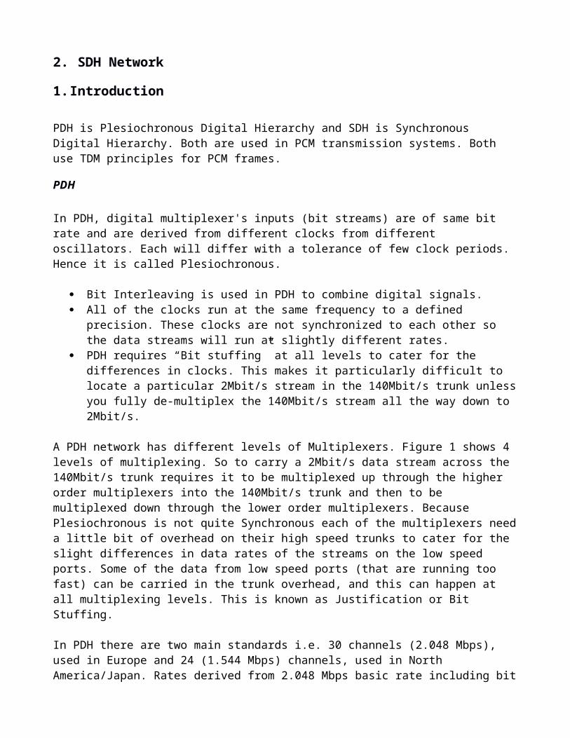
A PDH network has different levels of Multiplexers. Figure 1 shows 4 levels of multiplexing. So to carry a 2Mbit/s data stream across the 140Mbit/s trunk requires it to be multiplexed up through the higher order multiplexers into the 140Mbit/s trunk and then to be multiplexed down through the lower order multiplexers. Because Plesiochronous is not quite Synchronous each of the multiplexers need a little bit of overhead on their high speed trunks to cater for the slight differences in data rates of the streams on the low speed ports. Some of the data from low speed ports (that are running too fast) can be carried in the trunk overhead, and this can happen at all multiplexing levels. This is known as Justification or Bit Stuffing.
In PDH there are two main standards i.e. 30 channels (2.048 Mbps), used in Europe and 24 (1.544 Mbps) channels, used in North America/Japan. Rates derived from 2.048 Mbps basic rate including bit stuffing in 30 channel case are mentioned below. 2.048 x 4 gives 8.448 Mbps (120 channels).8.448 x 4 gives 34.368 Mbps (480 channels).34.368 x 4 gives 139.264 Mbps (1920 channels).139.264 x 4 gives 564.992 Mbps (7680 channels).
Fig 4.1.1: PDH Multiplexing Hierarchy
The limitations of PDH
· PDH is not very flexible As previously explained, it is not easy to identify individual channels in a higher order bit stream. You must demultiplex the high rate channel down through all multiplexing levels to find a particular lower speed channel. This requires an expensive and complex “multiplexer mountain”. · Lack of Performance It is not easy to provide good performance if you can’t monitor the performance in the first place. For PDH there is no international standard for performance monitoring and no agreed management channels. There are some spare overhead bits that are being used for management but they have limited bandwidth and are hard to locate in a 140M stream without de-multiplexing. · Lack of standards Not only does PDH have two totally different multiplexing hierarchies but it is quite weak on standards. For example there are no standards for data rates above 140Mbit/s and no standards for the line side of a “Line Transmission Terminal”.
SDH
SDH Advantages- Reduce costs
Simplified standard interfaces eliminate vendor proprietary interfaces- Integrated network elements
Enhanced operations capabilities.- Survivability
Grants upgradability (modularity).- No bandwidth bottle necks
1.1.1. SDH Network Elements Figure 4.1 shows the elements that make up an SDH network. · Path Terminating Element These are the end point devices where the lower speed channels enter and leave the SDH Network. These are known as “Path Level” devices. · Digital Cross Connect These devices can x-connect at the STM level down to individual E1 streams. So an E1 stream on one STM trunk could be x-connected to another STM trunk. In other words, it permits switching of transmission lines with different bit rates. It can also add/drop lower order signals. · Regenerator It is a device that regenerates the signal. It can also supervise the transmission quality of the line. · Add/Drop Multiplexer The Add/Drop mux adds and drops lower order speed channels into an STM stream.

Fig 4.1.1.1: SDH network elements
Fig 4.1.1.2: Digital Cross-connect (m<n)
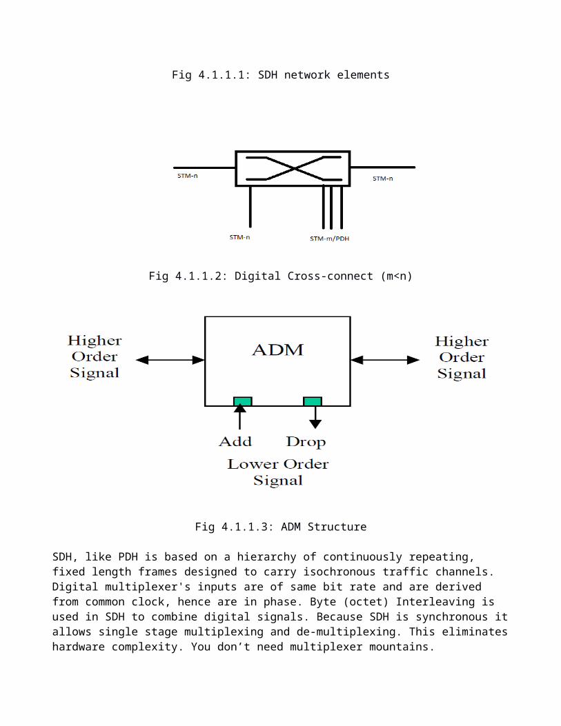
Fig 4.1.1.3: ADM Structure
SDH, like PDH is based on a hierarchy of continuously repeating, fixed length frames designed to carry isochronous traffic channels. Digital multiplexer's inputs are of same bit rate and are derived from common clock, hence are in phase. Byte (octet) Interleaving is used in SDH to combine digital signals. Because SDH is synchronous it allows single stage multiplexing and de-multiplexing. This eliminates hardware complexity. You don’t need multiplexer mountains.
All of the clocks are synchronized to a master reference clock. They may be out of phase with each other but they will run at exactly the same frequency.
Used in STM-1 (155.52Mbps), STM-4 (622.08Mbps), STM-16 (2.5Gbps), STM-64 (10Gbps) transmission systems.
World standard for optical interfaces. Networking is possible at the optical level. Greater flexibility in cross-connecting and demultiplexing of tributaries. More advance network management.
Any PDH rates up to 140 Mbps can be integrated with SDH rates up to 155.52 Mbps.
1.1.2. SDH Multiplexing Hierarchy
In the multiplexing process, payloads are layered into lower-order and higher-order virtual containers, each including a range of overhead functions for management and error monitoring. Transmission is then supported by the attachment of further layers of overheads. This layering of functions in SDH, both for traffic and management, suits the layered concept of a service-based network better than the transmission-oriented PDH standards. STM-1 forms the basis of the SDH frame structure. For example an STM-4 is a frame consisting of 4 x STM-1s.
Fig 4.1.3.1: SDH Multiplexing Hierarchy

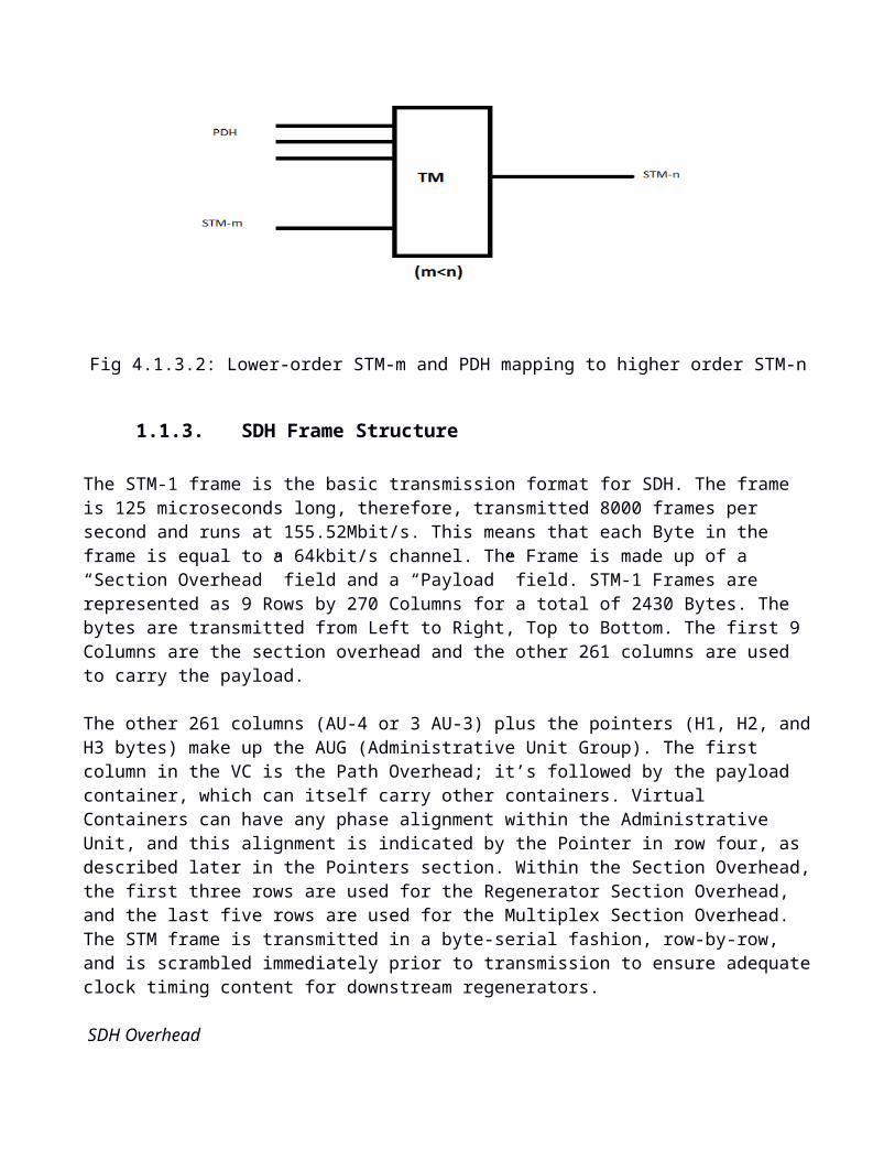
Fig 4.1.3.2: Lower-order STM-m and PDH mapping to higher order STM-n
1.1.3. SDH Frame Structure
The STM-1 frame is the basic transmission format for SDH. The frame is 125 microseconds long, therefore, transmitted 8000 frames per second and runs at 155.52Mbit/s. This means that each Byte in the frame is equal to a 64kbit/s channel. The Frame is made up of a “Section Overhead” field and a “Payload” field. STM-1 Frames are represented as 9 Rows by 270 Columns for a total of 2430 Bytes. The bytes are transmitted from Left to Right, Top to Bottom. The first 9 Columns are the section over-head and the other 261 columns are used to carry the payload.
The other 261 columns (AU-4 or 3 AU-3) plus the pointers (H1, H2, and H3 bytes) make up the AUG (Administrative Unit Group). The first column in the VC is the Path Overhead; it’s followed by the payload container, which can itself carry other containers. Virtual Containers can have any phase alignment within the Administrative Unit, and this alignment is indicated by the Pointer in row four, as described later in the Pointers section. Within the Section Overhead, the first three rows are used for the Regenerator Section Overhead, and the last five rows are used for the Multiplex Section Overhead. The STM frame is transmitted in a byte-serial fashion, row-by-row, and is scrambled immediately prior to transmission to ensure adequate clock timing content for downstream regenerators.
SDH Overhead
· Regenerator SectionThe Regenerator Section Overhead contains information required for the elements located at both ends of a section. This might be between two Regenerators or Line Termination Equipment.
· Multiplex SectionThe multiplex section overhead contains information required between the multiplex section termination equipment at each end of the Multiplex Section. Basically that means between consecutive network elements excluding Regenerators.
· PathThe Path overhead is created and terminated by the Path Terminating Equipment at either end of the link. It is transported in the Virtual Container with the user data.
(a)
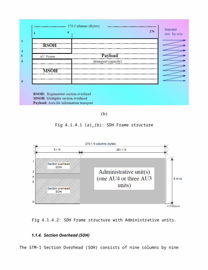
(b)
Fig 4.1.4.1 (a)_(b): SDH Frame structure
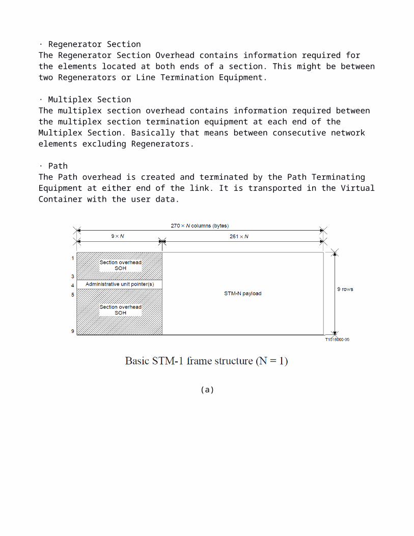
Fig 4.1.4.2: SDH Frame structure with Administrative units.
1.1.4. Section Overhead (SOH)
The STM-1 Section Overhead (SOH) consists of nine columns by nine rows as shown below. It forms the start of the STM-1 frame. The SOH contains control and status messages at the optical fiber level. First three rows are RSOH (Regenerator Section Overhead), Fourth row is AU (Administrative Unit) pointer. Fifth to Ninth rows are MSOH (Multiplexer section overhead).The section overhead (SOH) contains transport-support features such as framing, management-operations channels, and error monitoring, with the first segment containing the frame word for demultiplexer alignment.
Fig 4.1.4.1.1: SDH SOH
Framing octets (A1, A2): These two octets are used to determine start of the (STM-n) SDH frame. They are the first bytes
transmitted. Frame alignment takes place over three STM-1 frames.
Section Path Trace (J0): It is used to allow connected sections to verify whether the connection is still alive and with the right terminations or not. It contains a trace message that is continually transmitted between Regenerator Sections so that they know they are still connected.
Parity (B1): It provides parity checking, calculated over all bytes of the previous STM-1 frame. This parity octet is used by the receiver for bit error rate estimation. As this is of 8 bits, 8 parities are calculated.
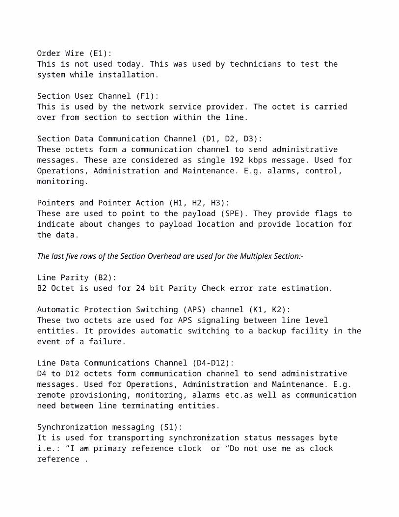
Order Wire (E1): This is not used today. This was used by technicians to test the system while installation.
Section User Channel (F1): This is used by the network service provider. The octet is carried over from section to section within the line.
Section Data Communication Channel (D1, D2, D3): These octets form a communication channel to send administrative messages. These are considered as single 192 kbps message. Used for Operations, Administration and Maintenance. E.g. alarms, control, monitoring.
Pointers and Pointer Action (H1, H2, H3): These are used to point to the payload (SPE). They provide flags to indicate about changes to payload location and provide location for the data.
The last five rows of the Section Overhead are used for the Multiplex Section:-
Line Parity (B2): B2 Octet is used for 24 bit Parity Check error rate estimation.
Automatic Protection Switching (APS) channel (K1, K2): These two octets are used for APS signaling between line level entities. It provides automatic switching to a backup facility in the event of a failure.
Line Data Communications Channel (D4-D12): D4 to D12 octets form communication channel to send administrative messages. Used for Operations, Administration and Maintenance. E.g. remote provisioning, monitoring, alarms etc.as well as communication need between line terminating entities.
Synchronization messaging (S1): It is used for transporting synchronization status messages byte i.e.: “I am primary reference clock” or “Do not use me as clock reference”.
STS-1 REI (M0): This octet sends no. of errors detected by B octets back to the transmitter. This helps in knowing line status as well as receiver status.

STS-N REI (M1): The function is same as listed in M0 above, for remote error indication
OrderWire (E2): The function is same as listed above for E1, a 64kbit/s voice channel between “Multiplex Sections”.
1.1.5. Path Overhead (POH)
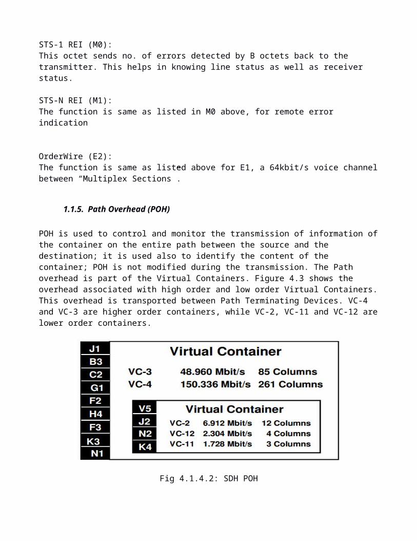
POH is used to control and monitor the transmission of information of the container on the entire path between the source and the destination; it is used also to identify the content of the container; POH is not modified during the transmission. The Path overhead is part of the Virtual Containers. Figure 4.3 shows the overhead associated with high order and low order Virtual Containers. This overhead is transported between Path Terminating Devices. VC-4 and VC-3 are higher order containers, while VC-2, VC-11 and VC-12 are lower order containers.
Fig 4.1.4.2: SDH POH
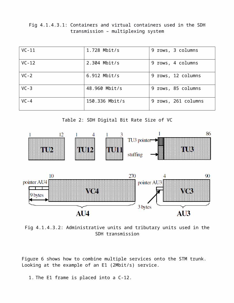
High Order Virtual Containers
Path Trace (J1): It helps two ends to verify the connection status (live or not) and check whether it is connected with right terminations. This byte repetitively transmits a user programmable data string so the receiving path device can see that it is still connected to the intended transmitting path device.
Path BIP-8(B3): It is used by the receiver for BER estimation.
STS Path Signal Label (C2): This indicates type of traffic carried in the payload part of the SDH frame. It specifies the type of mapping in the Virtual Container. For example it tells you if the High Order Virtual Container contains Lower Order Virtual Containers or ATM CELLs etc.
Path Status (G1):
It is used to convey path terminating status/performance back to the transmitter. PTE stands for Path Terminating Equipment.
Path user channel (F2): It is used for user communication similar to F1 octet in transport overhead. It’s used for communications between path elements.
Multi-frame indicator (H4): It provides generalized multi-frame indicator for the payloads.
Growth octets (Z3, Z4): Reserved for future use.
N1 fields: This octet is used to allocate support for tandem connection maintenance and tandem connection data link.
Low Order Virtual Containers
Inferior order containers (C11, C12 and C2) have the POH composed of 4 bytes distributed over 4 successive containers, one container including just a single POH byte.
There is only a single byte of overhead in a low order Virtual Container. This byte is used for the following purposes over a 4 byte multi frame.
V5 Error Checking, Path Status and Signal label (async, byte sync, bit sync)
Access path identifier (J2):To check if the receiver knows he is still connected to the intended transmitter
Connection Monitoring (N2):Used for monitoring the VC.
(APS) Automatic Protection Switching (K4):This is used to provide automatic switching to a backup facility in the event of a failure.
1.2. Virtual Containers
Container C – represents a bloc structure with imposed dimensions which contains data belonging to a tributary and doesn’t contain any control or management information.
There are containers with different dimensions adapted to the data generated by different PDH tribu-taries. The containers transport capacity is chosen larger than the rate of the corresponding PDH tribu-taries an appropriate positive justification is used to manage the rate deviation of the PDH signals from the nominal value.
Containers characteristics to the SDH system:• C4 – 149,76Mbps binary rate;
• C3 – 48,384Mbps binary rate;• C2 – 6,784Mbps binary rate;• C12 – 2,176Mbps binary rate;• C11 – 1,6Mbps binary rate;
• Higher order containers (C3 and C4) have the POH composed of a column of 9 bytes.• Lower order containers (C11, C12 and C2) have the POH composed of 4 bytes distributed over 4 suc-cessive containers, one container including just a single POH byte.
In SDH the actual user data is carried in “Virtual Containers”. The Virtual Containers have a PathOverhead field and they come in a number of different sizes. The Virtual Containers provide a perma-nent nailed up path across the network and there is no Dynamic Bandwidth Allocation.
The pointer is used to find the floating part of the AU or TU, which is called a virtual container (VC). The AU pointer locates a higher-order VC, and the TU pointer locates a lower-order VC. For example, an AU–3 contains a VC–3 plus a pointer, and a TU–2 contains a VC–2 plus a pointer. A VC is the pay-load entity that travels across the network, being created and dismantled at or near the service termina-tion point. PDH traffic signals are mapped into containers of appropriate size for the bandwidth re-quired, using single-bit justification to align the clock rates where necessary. POHs are then added for management purposes, creating a VC, and these overheads are removed later where the VC is disman-tled and the original signal is reconstituted. PDH traffic signals to be mapped into SDH are by defini-tion continuous. Each PDH signal is mapped into its own VC, and several VCs of the same nominal size are then multiplexed by byte interleaving into the SDH payload. This arrangement minimizes the delay experienced by each VC.
Fig 4.1.4.3.1: Containers and virtual containers used in the SDH transmission – multiplexing system
VC-11 1.728 Mbit/s 9 rows, 3 columns
VC-12 2.304 Mbit/s 9 rows, 4 columns
VC-2 6.912 Mbit/s 9 rows, 12 columns
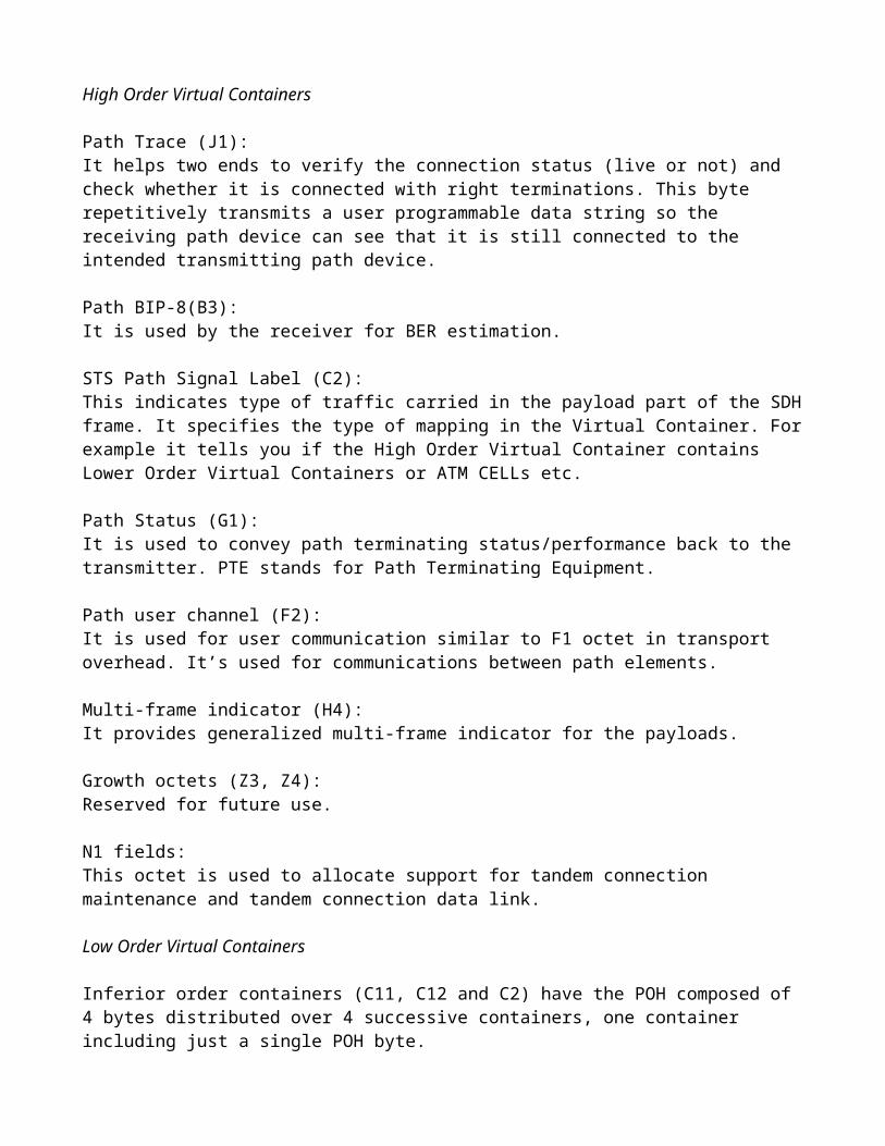
VC-3 48.960 Mbit/s 9 rows, 85 columns
VC-4 150.336 Mbit/s 9 rows, 261 columns
Table 2: SDH Digital Bit Rate Size of VC
Fig 4.1.4.3.2: Administrative units and tributary units used in the SDH transmission
Figure 6 shows how to combine multiple services onto the STM trunk. Looking at the example of an E1 (2Mbit/s) service.
1. The E1 frame is placed into a C-12.2. A Path overhead is added and it becomes a VC-12.3. Multiple VC-12s are assigned Pointers and become a TUG-2. The pointers indicate the location
of the first byte of each of the Virtual Containers.4. Seven of these TUGs can be mapped into a VC-3.5. Multiple (3) VC-3s will be assigned Pointers and placed into an AUG.6. The AUG is then placed in the STM Frame. The Pointers are used to locate individual 2M
streams in the STM Frame.

Fig 4.1.4.3.3: How a VC-12 fits into an STM-1 Frame
1.2.1. Virtual Containers Multiplexing Structure
At the lowest level, containers (C) are input to virtual containers (VC). The purpose of this function is to create a uniform VC payload by using bit-stuffing to bring all inputs to a common bit-rate ready for synchronous multiplexing. Various containers (ranging from VC-11 at 1.728 Mbit/s to VC-4 at 139.264 Mbit/s) are covered by the SDH hierarchy. Next, VCs are aligned into tributary units (TUs), where pointer processing operations are implemented.

These initial functions allow the payload to be multiplexed into TU groups (TUGs). As the figure illus-trates, the xN label indicates the multiplexing integer used to multiplex the TUs to the TUGs. The next step is the multiplexing of the TUGs to higher level VCs, and TUG-2 and TUG-3 are multiplexed into VC-3 and VC-4. These VCs are multiplexed with fixed byte-stuffing to form administration units (AUs) which are finally multiplexed into the AU group (AUG). This payload then is multiplexed into the Synchronous Transport Module (STM).
Mapping - A process used when tributaries are adapted into Virtual Containers (VCs) by adding justification bits and Path Overhead (POH) information.
Aligning - This process takes place when a pointer is included in a Tributary Unit (TU) or an Administrative Unit (AU), to allow the first byte of the Virtual Container to be located.
Multiplexing - This process is used when multiple lower-order path layer signals are adapted into a higher-order path signal, or when the higher-order path signals are adapted into a Multi-plex Section.
Stuffing - SDH has the ability to handle various input tributary rates from PDH. As the tributary signals are multiplexed and aligned, some spare capacity has been designed into the SDH frame to provide enough space for all these various tributary rates. Therefore, at certain points in the multiplexing hierarchy, this space capacity is filled with "fixed stuffing" bits that carry no infor-mation, but are required to fill up the particular frame.
Fig 4.1.4.4.1: Multiplexing Structure of PDH signals into SDH signal
Operations
Managing capacity in the network involves such operations as the following: Protection, for circuit recovery in milliseconds. Restoration, for circuit recovery in seconds or minutes. Provisioning, for the allocation of capacity to preferred routes.
Consolidation or the funneling of traffic from unfilled bearers onto fewer bearers in order to reduce waste of traffic capacity.
Grooming, or the sorting of different traffic types from mixed payloads into separate destinations for each type of traffic.
Fig 4.1.4.4.2: Traffic grooming and consolidation
2. Network Topology
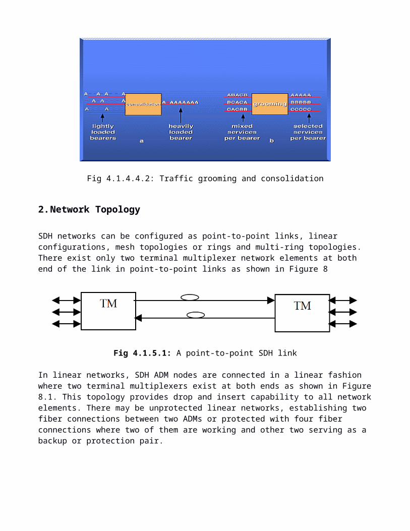
SDH networks can be configured as point-to-point links, linear configurations, mesh topologies or rings and multi-ring topologies. There exist only two terminal multiplexer network elements at both end of the link in point-to-point links as shown in Figure 8
Fig 4.1.5.1: A point-to-point SDH link
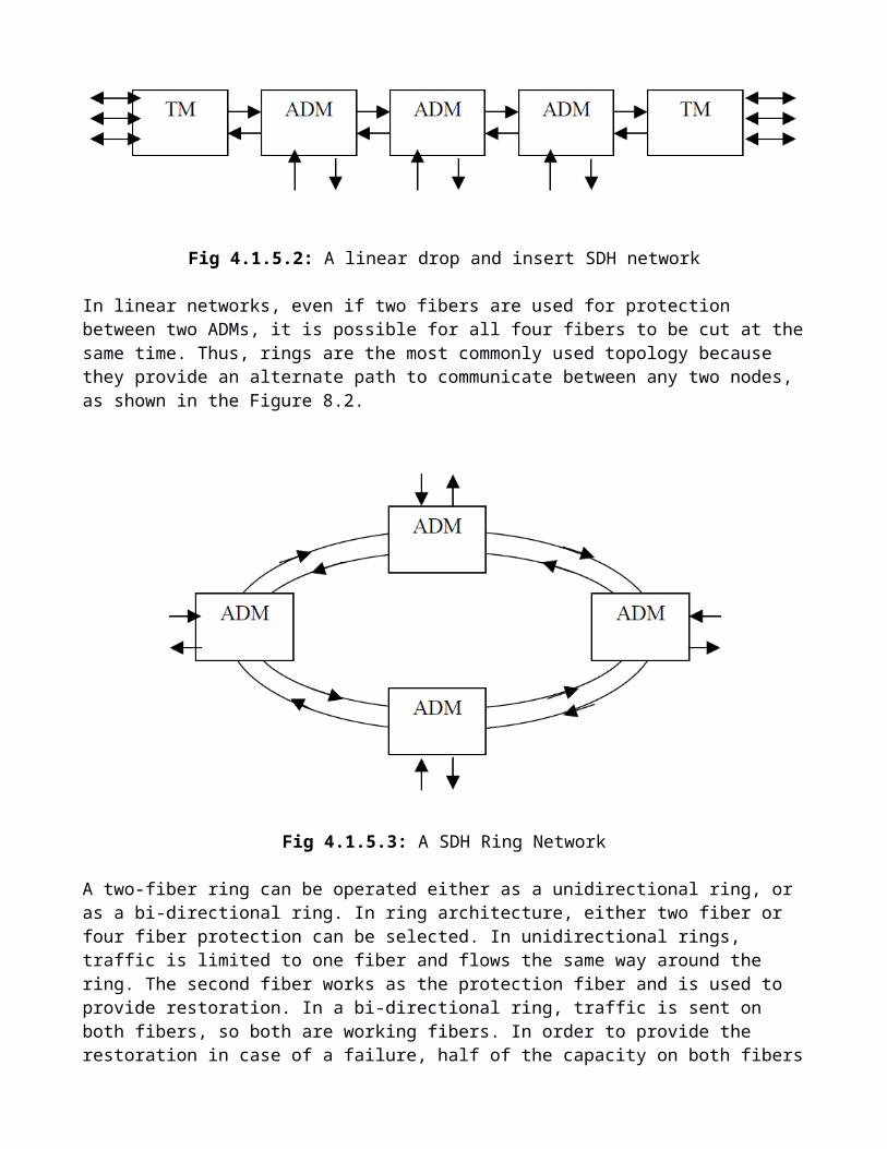
In linear networks, SDH ADM nodes are connected in a linear fashion where two terminal multiplexers exist at both ends as shown in Figure 8.1. This topology provides drop and insert capability to all net-work elements. There may be unprotected linear networks, establishing two fiber connections between two ADMs or protected with four fiber connections where two of them are working and other two serv-ing as a backup or protection pair.
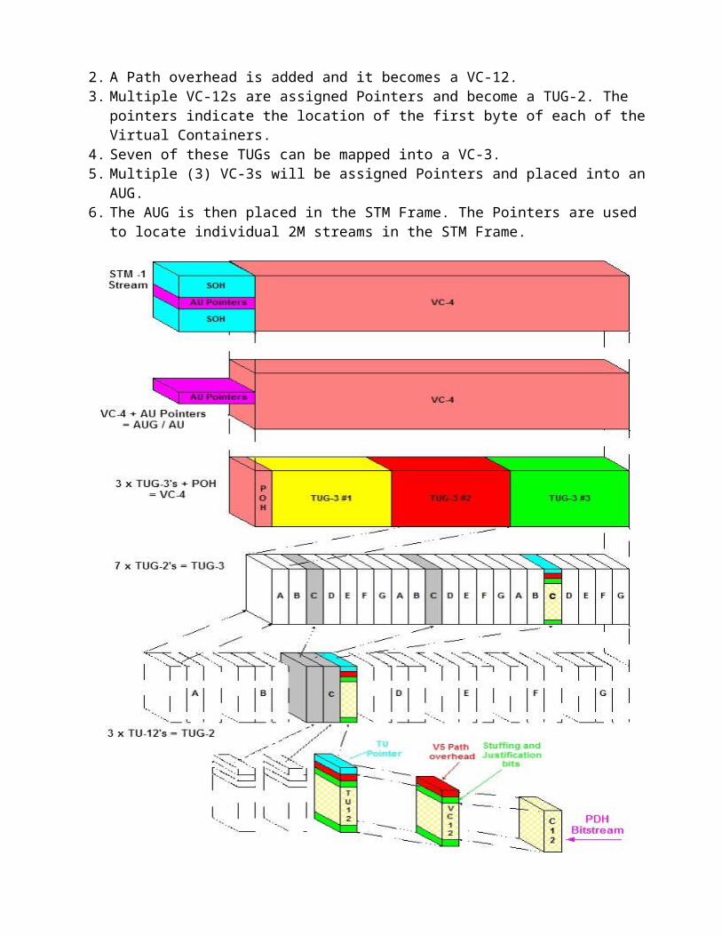
Fig 4.1.5.2: A linear drop and insert SDH network
In linear networks, even if two fibers are used for protection between two ADMs, it is possible for all four fibers to be cut at the same time. Thus, rings are the most commonly used topology because they provide an alternate path to communicate between any two nodes, as shown in the Figure 8.2.
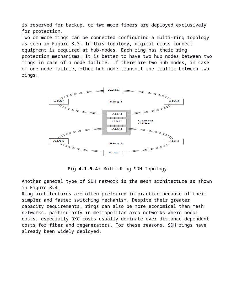
Fig 4.1.5.3: A SDH Ring Network
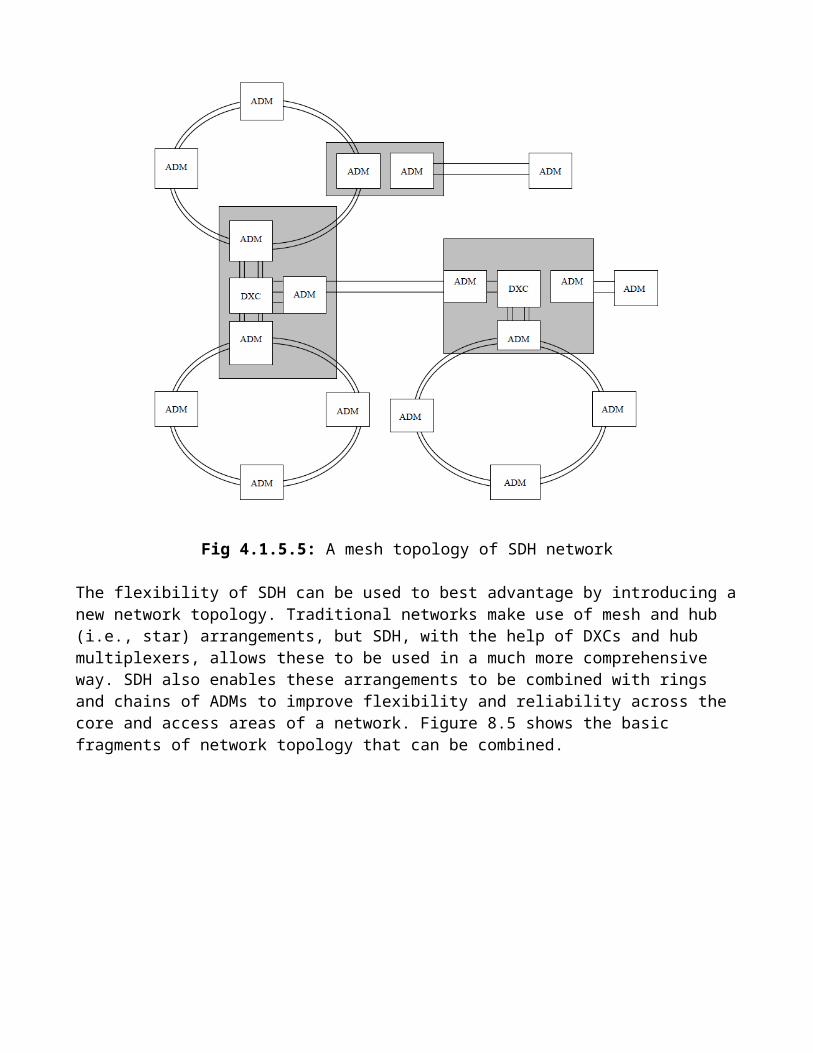
A two-fiber ring can be operated either as a unidirectional ring, or as a bi-directional ring. In ring archi-tecture, either two fiber or four fiber protection can be selected. In unidirectional rings, traffic is limited to one fiber and flows the same way around the ring. The second fiber works as the protection fiber and is used to provide restoration. In a bi-directional ring, traffic is sent on both fibers, so both are working fibers. In order to provide the restoration in case of a failure, half of the capacity on both fibers is re-served for backup, or two more fibers are deployed exclusively for protection.Two or more rings can be connected configuring a multi-ring topology as seen in Figure 8.3. In this topology, digital cross connect equipment is required at hub-nodes. Each ring has their ring protection mechanisms. It is better to have two hub nodes between two rings in case of a node failure. If there are two hub nodes, in case of one node failure, other hub node transmit the traffic between two rings.
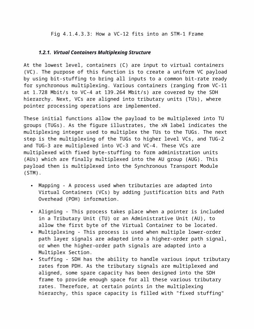
Fig 4.1.5.4: Multi-Ring SDH Topology
Another general type of SDH network is the mesh architecture as shown in Figure 8.4.Ring architectures are often preferred in practice because of their simpler and faster switching mecha-nism. Despite their greater capacity requirements, rings can also be more economical than mesh net-works, particularly in metropolitan area networks where nodal costs, especially DXC costs usually dominate over distance-dependent costs for fiber and regenerators. For these reasons, SDH rings have already been widely deployed.
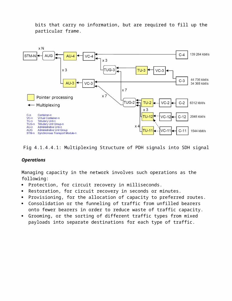
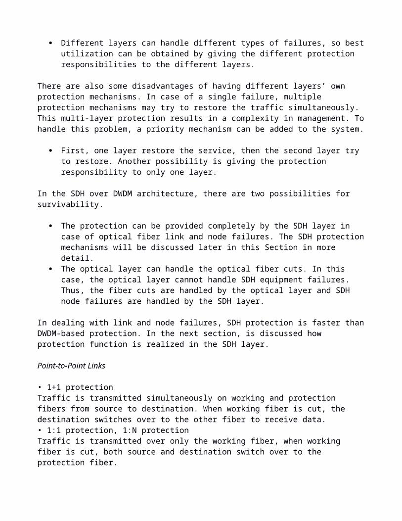
Fig 4.1.5.5: A mesh topology of SDH network
The flexibility of SDH can be used to best advantage by introducing a new network topology. Traditional networks make use of mesh and hub (i.e., star) arrangements, but SDH, with the help of DXCs and hub multiplexers, allows these to be used in a much more comprehensive way. SDH also enables these arrangements to be combined with rings and chains of ADMs to improve flexibility and reliability across the core and access areas of a network. Figure 8.5 shows the basic fragments of network topology that can be combined.
Fig 4.1.5.6: Basic Fragments of Network Topology
3. Protection Mechanism
Survivability
There are two main approaches to achieve survivability: protection, which uses dedicated capacity in the ring and mesh networks to restore the traffic when a failure occurs, and restoration, a dynamic re-routing algorithm for handling the interrupted traffic using paths available in the mesh networks.
Different telecommunications services may use different survivable architectures due to economics and demand distribution and network planners have a great concern of reducing network protection cost while supplying an acceptable level of survivability. The architectures to supply survivable networks are protection and restoration. Protection is pre-assigned capacities between any two nodes in a network in order to recover a failure, used in both ring and mesh networks. Restoration may or may not use any pre-assigned capacity. If no pre-assigned capacity is used, dynamic re-routing algorithms are used to find a transport path to recover an interrupted capacity. This technique is used generally in mesh networks. There are different protection/restoration possibilities having different recovery time, granularity and fault coverage specifications that result in different survivability performance.
We now introduce the term of layered architecture for the discussion of survivability in different network protocols. The functions of the network may be broken up into different layers. Each layer performs different functions and provides a set of services to the higher layer. Today’s network layering structures may be complex, and employ with several sub-layers and multiple protocol stacks. An example can be seen in Figure 2.6. In this example, an IP over ATM over SDH network is represented.
The SDH layer is treated as the data link layer of ATM layer and ATM layer is treated as the data link layer of above IP layer.
Fig: 4.1.6.1: An IP over ATM over SDH network
These layers are called the first-generation networks. The second-generation networks introduces optical layer in the protocol hierarchy. The optical layer has been defined by the ITU. This definition is appropriate to describe DWDM networks. This second generation optical layer provides light paths to the first-generation network layers. A light path is an end-to-end connection across the optical network, and on each link, a wavelength is used to establish the connection. In public and private telecommunications networks, first-generation optical networks, especially SDH networks have been widely deployed. With the advances in DWDM technology, carriers are widely using the SDH over DWDM architecture shown in Figure 2.7.
Fig 4.1.6.2: A SDH layer over optical layer
The SDH layer consists of four sub-layers. The highest layer is the path layer and responsible for end-to-end connections between nodes. The path layer corresponds to the network layer in classical layered hierarchy. The line layer is responsible for multiplexing a set of path-layer connections onto the link between two nodes and for performing the protection switching in case of a line failure. The section layer above the physical layer is present at each regenerator and terminal in the network. The line layer and section layer correspond to the data link layer in classical layered hierarchy. The lowest physical layer is responsible for actual transmission of traffic across the fiber. The physical layer of SDH is replaced by the optical layer. The optical layer also consists of the channel, multiplex and amplifier sections.
A network consists of many layers and the multi-layer model is a complicated structure as a result of different networks working with each other. Each layer in the hierarchy has their own protection mechanisms, independent of other layers. Having different protection mechanisms in different layers have some advantages and also some disadvantages.
The advantages of having separate protection mechanisms in different layers are as follows. If one of the layers does not have any protection mechanisms, other layers can provide the protection in case of a failure.
Different layers can handle different types of failures, so best utilization can be obtained by giving the different protection responsibilities to the different layers.
There are also some disadvantages of having different layers’ own protection mechanisms. In case of a single failure, multiple protection mechanisms may try to restore the traffic simultaneously. This multi-layer protection results in a complexity in management. To handle this problem, a priority mechanism can be added to the system.
First, one layer restore the service, then the second layer try to restore. Another possibility is giving the protection responsibility to only one layer.
In the SDH over DWDM architecture, there are two possibilities for survivability.
The protection can be provided completely by the SDH layer in case of optical fiber link and node failures. The SDH protection mechanisms will be discussed later in this Section in more detail.
The optical layer can handle the optical fiber cuts. In this case, the optical layer cannot handle SDH equipment failures. Thus, the fiber cuts are handled by the optical layer and SDH node failures are handled by the SDH layer.
In dealing with link and node failures, SDH protection is faster than DWDM-based protection. In the next section, is discussed how protection function is realized in the SDH layer.
Point-to-Point Links
• 1+1 protectionTraffic is transmitted simultaneously on working and protection fibers from source to destination. When working fiber is cut, the destination switches over to the other fiber to receive data.• 1:1 protection, 1:N protectionTraffic is transmitted over only the working fiber, when working fiber is cut, both source and destina-tion switch over to the protection fiber.
Comparison of 1+1 and 1:1 protection
• 1+1 protection is faster and requires no signaling protocol, while 1:1 needs protocol• Protection fiber in 1:1 scheme can transmit lower priority traffic under normal operation• 1:1 protection can be extended to share a single protection fiber among many working fibers (1:N)
The ring protection types are as follows;In Europe: 2f-MS-SPRing, 4f-MS-SPRing or 2f-SNCPIn USA: 2f-BLSR, 4f-BLSR or 2f-UPSRWhere, BLSR: Bi-Directional Line-Switched RingsUPSR: Uni-Directional Path-Switched RingsMS-SPRing: Multiplex Section-Shared Protected RingsSNCP: Sub-Network Connection Protection.
In SDH networks, point-to-point connections are widely replaced by ring structures. A ring network is a 2 way connected structure and there are two separate paths between any pairs of nodes. This provides resilience to any single failure. When a failure occurs on a link, the traffic is rerouted over the paths on the reserved capacity of the ring. This protection is called as ring protection. The most popular protec-tion architecture of SDH is self-healing rings in network protection. Since ring networks have several advantages such as fast restoration time, simple operation and cost effective, the usage of ring networks are now very common for survivability design. In this analysis, i only consider single link failures, and the protection is provided by only the SDH layer.
How the traffic is rerouted in case of a failure- Path switching- Span switching- Ring switching
Different protection schemes operate at different layers in the network and at different sub layers within a layer.
Fig 4.1.6.3: switching schemes
SDH rings are also called self-healing rings since they incorporate protection mechanisms that detect failures and reroute traffic onto reserved channels rapidly. In a dedicated protection ring, every normal path has a corresponding protection path and in a shared protection ring, several normal paths may use a single protection path. Although SDH meshed architectures offer more advanced functionalities and ring networks require high capacity and have limited flexibility, ring networks have dominant advan-tages as fast restoration, being economical, practical and easy management. The main advantage of ring protection schemes is fast restoration time since the network switching time is a major factor for the transmission networks. The nodes adjacent to a section or node failure are responsible for the protec-tion switching action. Protection is shared at the Multiplex Section level by dividing the capacity of the SDH frames in half for service and protection channels.
The communication protocol restricts the number of nodes to 16 in a ring in the MS-SPRing mecha-nisms. There are two types of MS-SPRing; 2-fiber and 4-fiber rings that are shown in Fig. 4.1.6.4, Fig. 4.1.6.5 respectively.
Fig 4.1.6.4: Two-fiber MS-SPRing
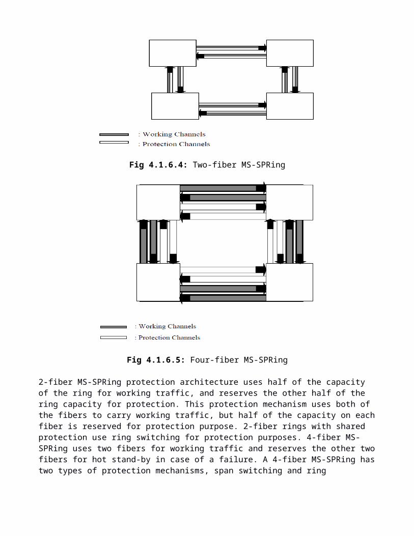
Fig 4.1.6.5: Four-fiber MS-SPRing

2-fiber MS-SPRing protection architecture uses half of the capacity of the ring for working traffic, and reserves the other half of the ring capacity for protection. This protection mechanism uses both of the fibers to carry working traffic, but half of the capacity on each fiber is reserved for protection purpose. 2-fiber rings with shared protection use ring switching for protection purposes. 4-fiber MS-SPRing uses two fibers for working traffic and reserves the other two fibers for hot stand-by in case of a failure. A 4-fiber MS-SPRing has two types of protection mechanisms, span switching and ring switching. 4-fiber rings enable the protection mechanisms of either ring or span switching, but not both of them simulta-neously.
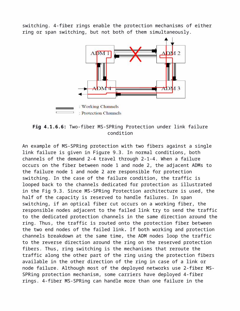
Fig 4.1.6.6: Two-fiber MS-SPRing Protection under link failure condition
An example of MS-SPRing protection with two fibers against a single link failure is given in Figure 9.3. In normal conditions, both channels of the demand 2-4 travel through 2-1-4. When a failure occurs on the fiber between node 1 and node 2, the adjacent ADMs to the failure node 1 and node 2 are re-sponsible for protection switching. In the case of the failure condition, the traffic is looped back to the channels dedicated for protection as illustrated in the Fig 9.3. Since MS-SPRing Protection architecture is used, the half of the capacity is reserved to handle failures. In span switching, if an optical fiber cut occurs on a working fiber, the responsible nodes adjacent to the failed link try to send the traffic to the dedicated protection channels in the same direction around the ring. Thus, the traffic is routed onto the protection fiber between the two end nodes of the failed link. If both working and protection channels breakdown at the same time, the ADM nodes loop the traffic to the reverse direction around the ring on the reserved protection fibers. Thus, ring switching is the mechanisms that reroute the traffic along the other part of the ring using the protection fibers available in the other direction of the ring in case of a link or node failure. Although most of the deployed networks use 2-fiber MS-SPRing protection mech-anism, some carriers have deployed 4-fiber rings. 4-fiber MS-SPRing can handle more than one failure in the network. However, management of 4-fiber ring is more complicated than 2- fiber MS-SPRing because multiple protection mechanisms must be coordinated. In SNCP ring protection architecture, every demand is duplicated at the origin node and routed to both ways around the ring, in which a main path along one side of the ring and a dedicated backup path along the other side of the ring as seen in Fig. 9.4. In the case of a failure, the receiving node selects the protection path through switching estab-lishing 1:1 selection.

Fig 4.1.6.7: SNCP Protection under link failure condition
In MS-SPRing, the bandwidth is bounded with the largest sum of traffic routed over any span, also re-serving 100% extra capacity for protection; whereas in SNCP, the ring bandwidth must be at least the sum of all traffic demands in the ring. If the traffic is more evenly distributed around the ring, MS-SPRing is more capacity efficient than SNCP rings. Furthermore, it is possible to transmit extra low-priority traffic on the protection capacity, whereas this is not supported in SNCP rings since the protec-tion capacity is used for the protection switching operation. The extra traffic transmission possibility is only available on protection channels under normal conditions; in case of a failure the low-priority traf-fic is not considered and will be preempted. There is no limit on the number of nodes in a SNCP ring, and SNCP rings are easy to implement because of their simple protection mechanisms. 2 or 4-fibre MS-SPRing has some advantages over SNCP rings whenever traffic sources and destinations are more evenly distributed around the ring. Furthermore, although it is possible to support extra low-priority traffic on the protection capacity of MS-Spring architecture, it is not possible in a SNCP ring network since the protection capacity is always used for the protection switching operation.
4. SDH Network conclusion
SDH has addressed the weaknesses of PDH. It transmits data in Virtual Containers and uses pointers to locate a low speed channel in a high speed trunk. Carriers like SDH because it provides:-
· A Robust Ring Architecture with Self-Healing Capabilities· Good Provisioning and Management Attributes· Strong International Standards

2.1. WDM
5. Introduction
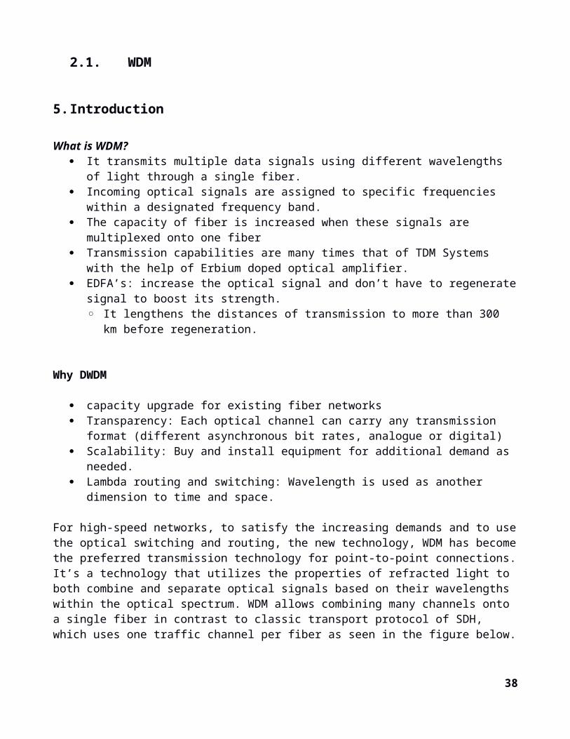
What is WDM? It transmits multiple data signals using different wavelengths of light through a single fiber. Incoming optical signals are assigned to specific frequencies within a designated frequency
band. The capacity of fiber is increased when these signals are multiplexed onto one fiber Transmission capabilities are many times that of TDM Systems with the help of Erbium doped
optical amplifier. EDFA’s: increase the optical signal and don’t have to regenerate signal to boost its strength.
◦ It lengthens the distances of transmission to more than 300 km before regeneration.
Why DWDM
capacity upgrade for existing fiber networks Transparency: Each optical channel can carry any transmission format (different asynchronous
bit rates, analogue or digital) Scalability: Buy and install equipment for additional demand as needed. Lambda routing and switching: Wavelength is used as another dimension to time and space.
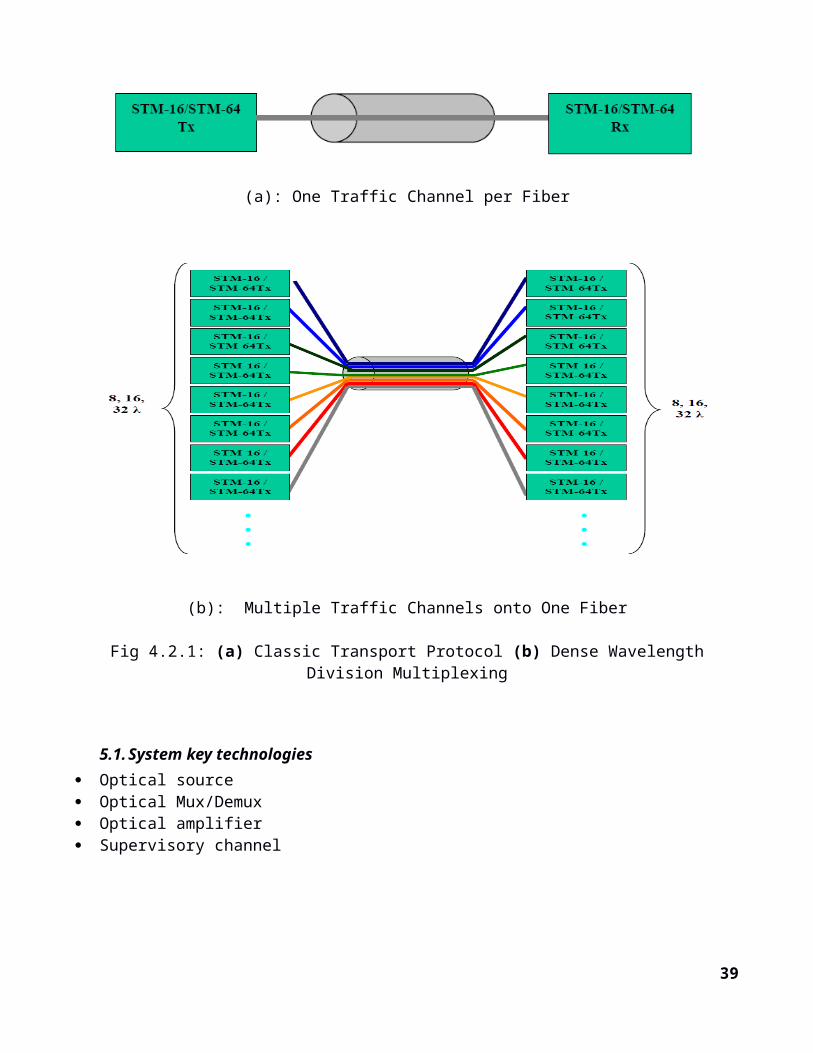
For high-speed networks, to satisfy the increasing demands and to use the optical switching and routing, the new technology, WDM has become the preferred transmission technology for point-to-point connections.It’s a technology that utilizes the properties of refracted light to both combine and separate optical signals based on their wavelengths within the optical spectrum. WDM allows combining many channels onto a single fiber in contrast to classic transport protocol of SDH, which uses one traffic channel per fiber as seen in the figure below.
(a): One Traffic Channel per Fiber
30
(b): Multiple Traffic Channels onto One Fiber
Fig 4.2.1: (a) Classic Transport Protocol (b) Dense Wavelength Division Multiplexing
5.1. System key technologies Optical source Optical Mux/Demux Optical amplifier Supervisory channel
31
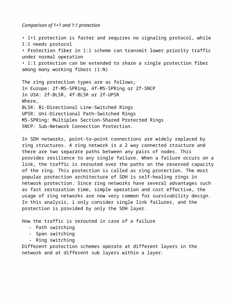
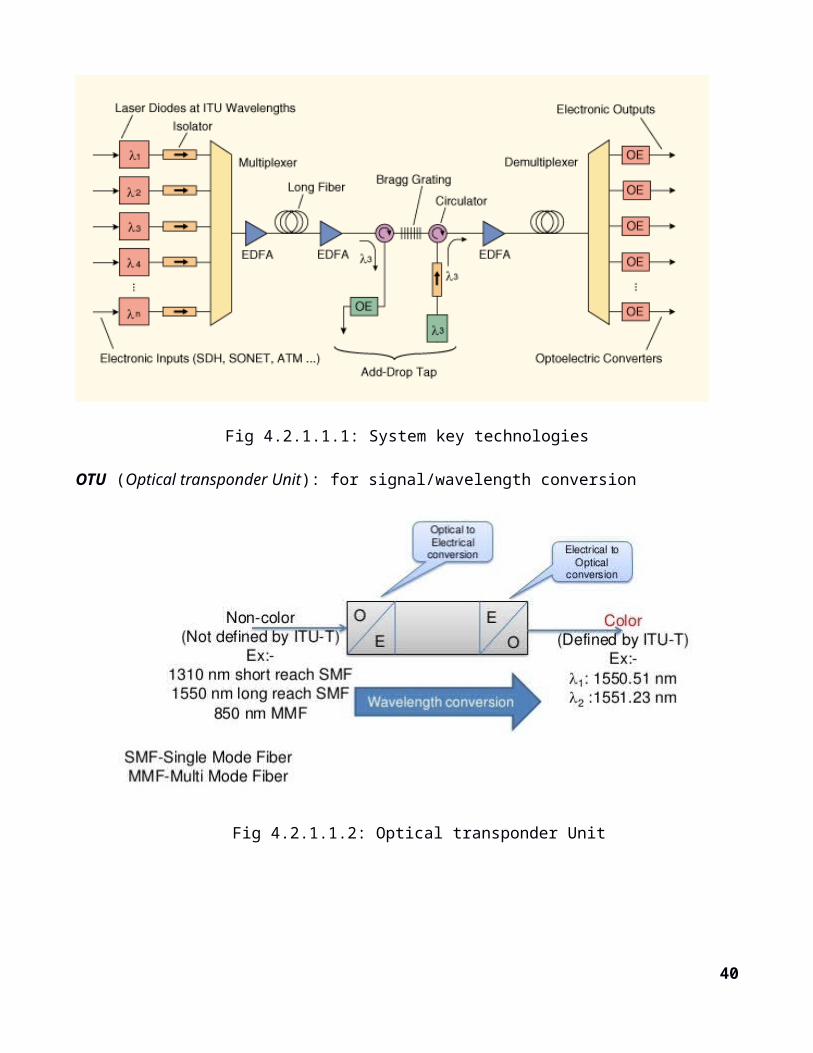
Fig 4.2.1.1.1: System key technologies
OTU (Optical transponder Unit): for signal/wavelength conversion
Fig 4.2.1.1.2: Optical transponder Unit
Fig 4.2.1.1.3: Transponder/Muxponder Unit to Mux/Demux Unit
Optical Multiplexer/Demultiplexer:
TFFThin Film Fiber
32

Number of channels <16AWG
Arrayed wavelength gratingNumber of channels >=16
Supervisory channel
OSC (Optical SC):- Often used in backbone systems- Uses OTN framing, similar to SDH- Costly
ESC (Electrical SC):- Often used in metropolitan systems- OTU is mandatory at every site. OLA sites don’t have OTU; therefore, you can’t manage OLAs
with ESC.
Fiber cable types:
G.652G.653 - Main application in submarine fibers.G.655 - Best for WDM, Expensive.
5.2. WDM Transmission Challenges
AttenuationIt is the extent to which lighting intensity from the source is diminished as it passes through a given length of fiber.Attenuation is caused by: - intrinsic factors primarily scattering and absorption- extrinsic factors, including stress from the manufacturing process, the environment, and physical bending
Rayleigh scattering - is an issue at shorter wavelengths
Attenuation due to absorption- is an issue at longer wavelengths - The intrinsic properties of the material - Impurities in the glass, and any atomic defects in the glass. These impurities absorb the optical energy, causing the light to become dimmer.
DispersionDispersion is the spreading of light pulses as they travel down optical fiber. Dispersion results in distortion of the signal, which limits the bandwidth of the fiber.
Chromatic Dispersion - is linear Chromatic dispersion occurs because different wavelengths propagate at different speeds. Increases as the square of the bit rate.
33
Polarization Mode Dispersion - is nonlinear. Polarization mode dispersion (PMD) is caused by ovality of the fiber shape as a result of the
manufacturing process or from external stressors.
2.1.1.1. WDM Installation
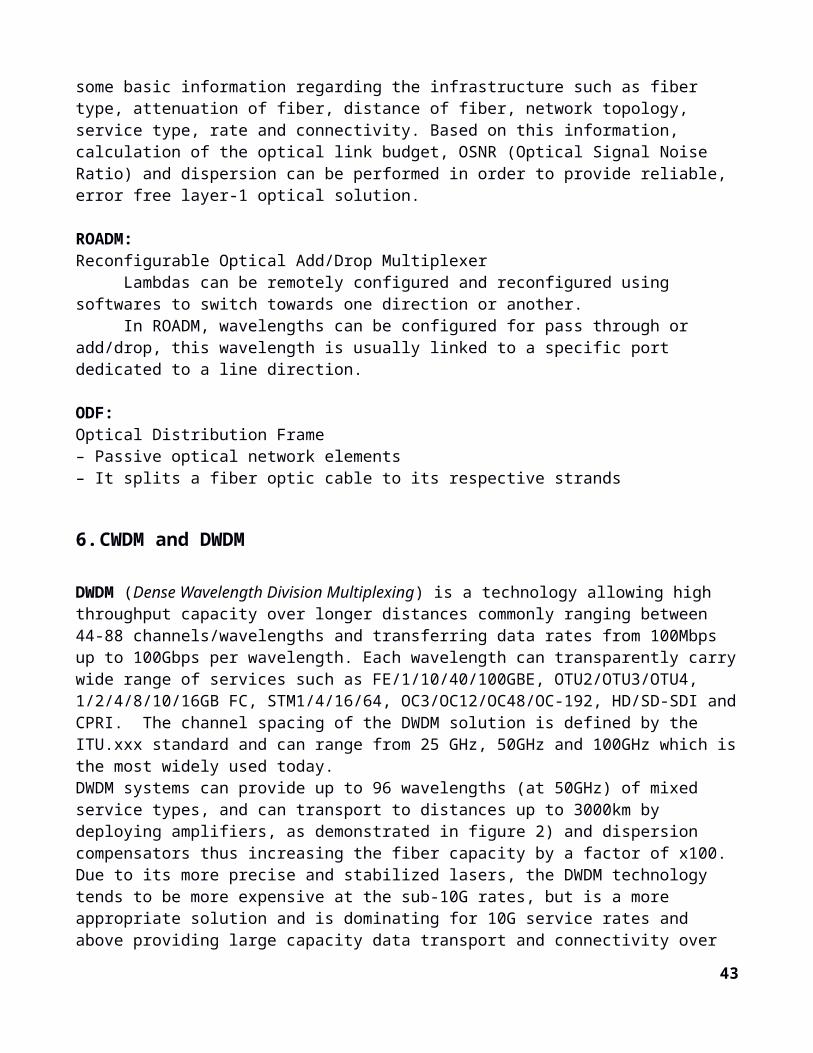
For designing and implementing a WDM network, there is a need to know some basic information regarding the infrastructure such as fiber type, attenuation of fiber, distance of fiber, network topology, service type, rate and connectivity. Based on this information, calculation of the optical link budget, OSNR (Optical Signal Noise Ratio) and dispersion can be performed in order to provide reliable, error free layer-1 optical solution.
ROADM:Reconfigurable Optical Add/Drop Multiplexer
Lambdas can be remotely configured and reconfigured using softwares to switch towards one direction or another.
In ROADM, wavelengths can be configured for pass through or add/drop, this wavelength is usually linked to a specific port dedicated to a line direction.
ODF:Optical Distribution Frame– Passive optical network elements– It splits a fiber optic cable to its respective strands
6. CWDM and DWDM
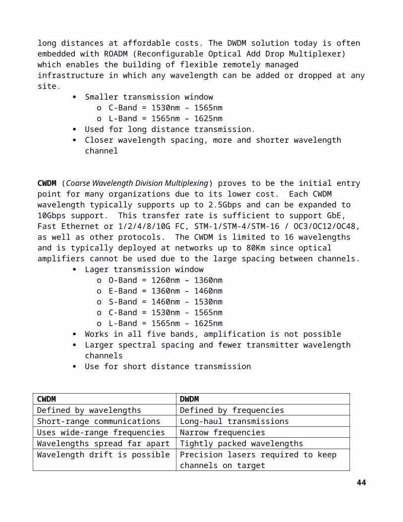
DWDM (Dense Wavelength Division Multiplexing) is a technology allowing high throughput capacity over longer distances commonly ranging between 44-88 channels/wavelengths and transferring data rates from 100Mbps up to 100Gbps per wavelength. Each wavelength can transparently carry wide range of services such as FE/1/10/40/100GBE, OTU2/OTU3/OTU4, 1/2/4/8/10/16GB FC, STM1/4/16/64, OC3/OC12/OC48/OC-192, HD/SD-SDI and CPRI. The channel spacing of the DWDM solution is defined by the ITU.xxx standard and can range from 25 GHz, 50GHz and 100GHz which is the most widely used today. DWDM systems can provide up to 96 wavelengths (at 50GHz) of mixed service types, and can transport to distances up to 3000km by deploying amplifiers, as demonstrated in figure 2) and dispersion compensators thus increasing the fiber capacity by a factor of x100. Due to its more precise and stabilized lasers, the DWDM technology tends to be more expensive at the sub-10G rates, but is a more appropriate solution and is dominating for 10G service rates and above providing large capacity data transport and connectivity over long distances at affordable costs. The DWDM solution today is often embedded with ROADM (Reconfigurable Optical Add Drop Multiplexer) which enables the building of flexible remotely managed infrastructure in which any wavelength can be added or dropped at any site.
Smaller transmission windowo C-Band = 1530nm – 1565nmo L-Band = 1565nm – 1625nm
Used for long distance transmission.
34
Closer wavelength spacing, more and shorter wavelength channel
CWDM (Coarse Wavelength Division Multiplexing) proves to be the initial entry point for many organizations due to its lower cost. Each CWDM wavelength typically supports up to 2.5Gbps and can be expanded to 10Gbps support. This transfer rate is sufficient to support GbE, Fast Ethernet or 1/2/4/8/10G FC, STM-1/STM-4/STM-16 / OC3/OC12/OC48, as well as other protocols. The CWDM is limited to 16 wavelengths and is typically deployed at networks up to 80Km since optical amplifiers cannot be used due to the large spacing between channels.
Lager transmission windowo O-Band = 1260nm – 1360nmo E-Band = 1360nm – 1460nmo S-Band = 1460nm – 1530nmo C-Band = 1530nm – 1565nmo L-Band = 1565nm – 1625nm
Works in all five bands, amplification is not possible Larger spectral spacing and fewer transmitter wavelength channels Use for short distance transmission
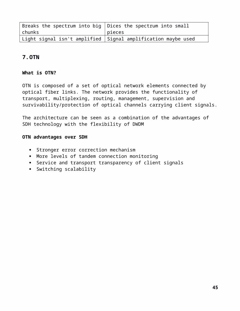
CWDM DWDMDefined by wavelengths Defined by frequenciesShort-range communications Long-haul transmissionsUses wide-range frequencies Narrow frequenciesWavelengths spread far apart Tightly packed wavelengthsWavelength drift is possible Precision lasers required to keep channels on targetBreaks the spectrum into big chunks Dices the spectrum into small piecesLight signal isn't amplified Signal amplification maybe used
7. OTN
What is OTN?
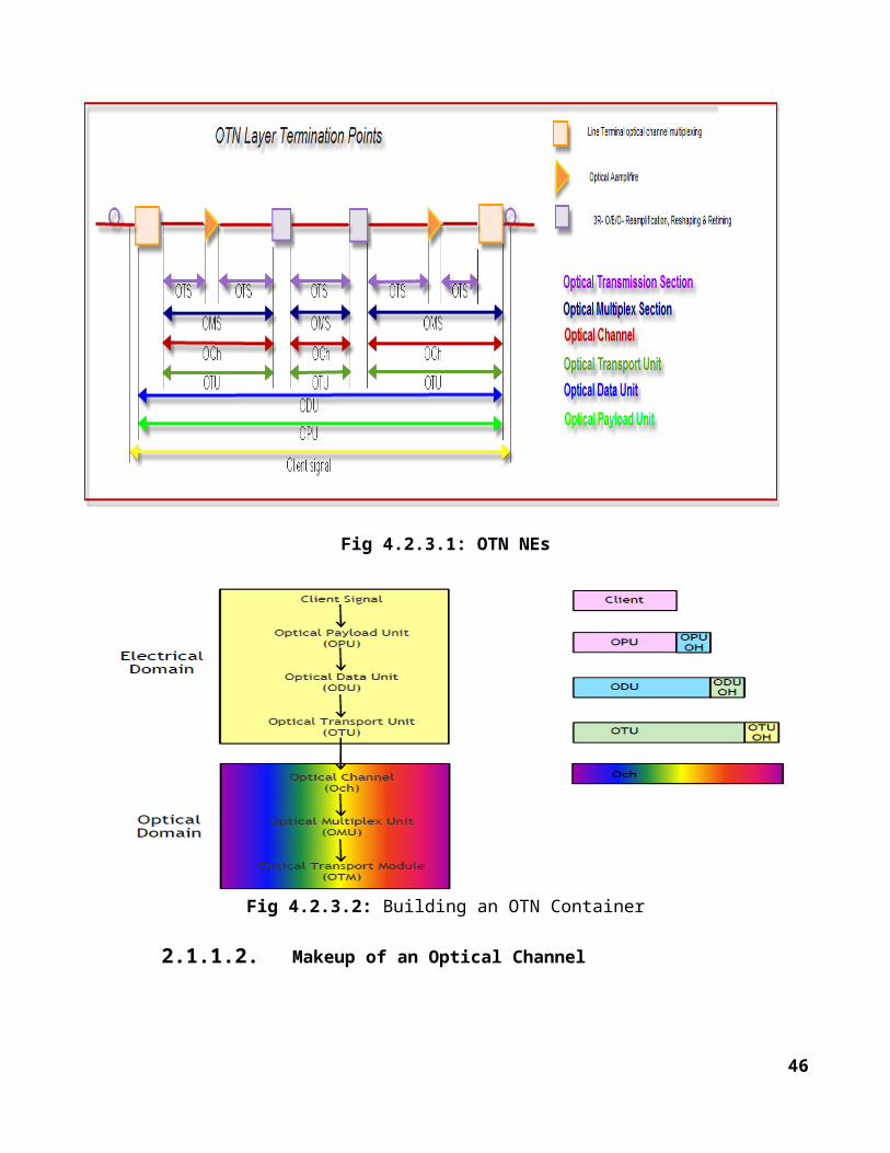
OTN is composed of a set of optical network elements connected by optical fiber links. The network provides the functionality of transport, multiplexing, routing, management, supervision and survivability/protection of optical channels carrying client signals.
The architecture can be seen as a combination of the advantages of SDH technology with the flexibility of DWDM
OTN advantages over SDH
Stronger error correction mechanism More levels of tandem connection monitoring Service and transport transparency of client signals Switching scalability
35
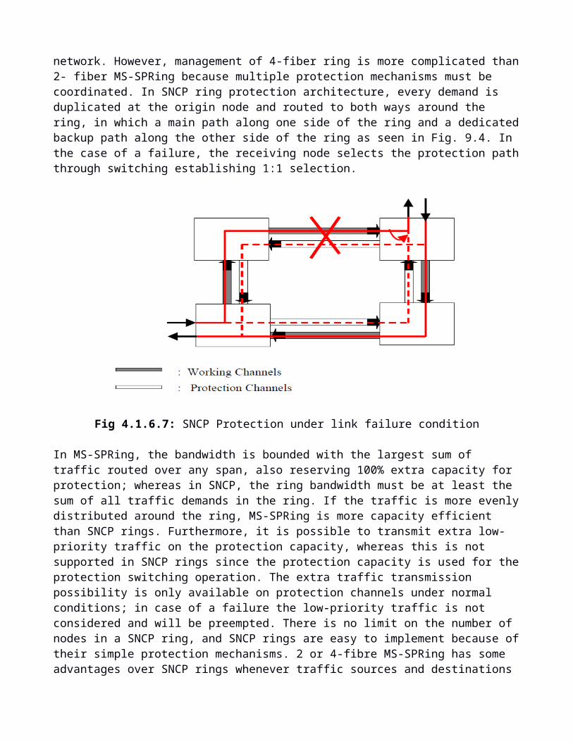
Fig 4.2.3.1: OTN NEs
Fig 4.2.3.2: Building an OTN Container
2.1.1.2. Makeup of an Optical Channel
36
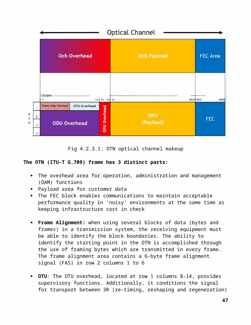
Fig 4.2.3.1: OTN optical channel makeup
The OTN (ITU-T G.709) frame has 3 distinct parts:
The overhead area for operation, administration and management (OAM) functions Payload area for customer data The FEC block enables communications to maintain acceptable performance quality in ‘noisy’
environments at the same time as keeping infrastructure cost in check
Frame Alignment: when using several blocks of data (bytes and frames) in a transmission system, the receiving equipment must be able to identify the block boundaries. The ability to identify the starting point in the OTN is accomplished through the use of framing bytes which are transmitted in every frame. The frame alignment area contains a 6-byte frame alignment signal (FAS) in row 2 columns 1 to 6
OTU: The OTU overhead, located at row 1 columns 8-14, provides supervisory functions. Additionally, it conditions the signal for transport between 3R (re-timing, reshaping and regeneration) points in the OTN. The OTU overhead consists of three bytes for section monitoring (SM), a two-byte general communications channel, and two bytes reserved for future international standardization
ODU: The ODU overhead resides in columns 1-14 of rows 2, 3 and 4 of the OTN frame. The ODU information structure provides tandem connection monitoring (TCM), end-to-end path supervision, and client signal adaptation via the optical channel payload unit (OPU). The ODU also defines six fields for TCM which enables a network operator to monitor the error performance of a signal transiting from its own network ingress and egress points.
37
OPU: The OPU overhead is added to the OPU payload and contains information to support the adaptation of client signals. The OPU overhead is located in rows 1-4 of columns 15 and 16 and is terminated where the OPU is assembled and disassembled.
2.1.1.3. OTN Hierarchy
Fig 4.2.3.2: OTN Data signal Hierarchy
OTN can be implemented as an overlay to an existing network or as a replacement.
HO-OTN networking is used when the client throughput does not need further aggregation within the lambdaLO-OTN networking is used when sub-lambda multiplexing is needed.Switching can be accomplished by means of fast electronic technology and/or slower photonic technology
2.1.1.4. How Does OTN Technology Expand Carrier Applications?
OTN Supports Several Emerging Market Opportunities
Optical Wavelength Services offers customers full end-to-end transparency Protocol-independent transmission of SDH, Ethernet, IP, and/or Lambdas Simplifies end-customer network management Ideal for Carrier’s carrier applications, wholesale bandwidth services, etc.
Differentiated Services New Service Level Agreement (SLA) options
– Via OTN Control-Plane mesh New Integrated multi-domain operations
38
– E.g. Multi-Region Networking to integrate Physical, Transport, and Data layers under a common network management model for customer control
Bandwidth on Demand Services– Fast provisioning via end to end OTN
2.1.1.5. How Does OTN Technology Benefit Today’s Carriers?
OTN Technology Delivers Value Across Many “Domains”
COMMONALITY - via wavelength-based optical transport Payload equivalency for SDH, Ethernet, and/or DWDM transport Common network management platform support Permits ‘endpoint-only’ management by avoiding termination at every midpoint
TRANSPARENCY – across the optical domain Integrates physical and optical layers for seamless networking Promotes integration across disparate networks via common transport framework
EFFICIENCY – for overall cost reduction and network monetization Simplified multiplexing/demultiplexing of sub-rate traffic Reduction in signal overhead requirements relative to payload
EVOLUTION – to emerging technologies Provides simple transition to 40G and 100G transmission speeds Purpose-built for Packet Optical and Wavelength-based transport Integrated, standardized Forward Error Correction (FEC) for extended optical reach Ideal for comprehensive Control-Plane network implementation
8. DWDM Network Topology
A network can be physically structured in the form of either a ring, a mesh, star based or linear bus based on the connection between the various nodes. Although the physical topology of a DWDM system might be that of a ring, the logical traffic distribution topology can be arbitrary. This is done through the use of different wavelengths to interconnect each node. Until the development of EDFAs the passive star configuration was the most popular configuration due to its superior power budget. However, with the advent of EDFAs, the ring network works out much better after overcoming its power budget problems. What makes the ring network better is its superior resilience. The Optical Cross Connect (OXC) helps pass on traffic between each of the rings. A Path-in-Lambda architecture for connecting all-optical networks is under development.
PTP costRing complexityMesh Reliability
8.1.Point-to-Point Topologies
39
As we move down the topologies from PTP-Ring-Mesh, cost, complexity and reliability increases
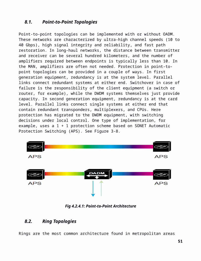
Point-to-point topologies can be implemented with or without OADM. These networks are characterized by ultra-high channel speeds (10 to 40 Gbps), high signal integrity and reliability, and fast path restoration. In long-haul networks, the distance between transmitter and receiver can be several hundred kilometers, and the number of amplifiers required between endpoints is typically less than 10. In the MAN, amplifiers are often not needed. Protection in point-to-point topologies can be provided in a couple of ways. In first generation equipment, redundancy is at the system level. Parallel links connect redundant systems at either end. Switchover in case of failure is the responsibility of the client equipment (a switch or router, for example), while the DWDM systems themselves just provide capacity. In second generation equipment, redundancy is at the card level. Parallel links connect single systems at either end that contain redundant transponders, multiplexers, and CPUs. Here protection has migrated to the DWDM equipment, with switching decisions under local control. One type of implementation, for example, uses a 1 + 1 protection scheme based on SONET Automatic Protection Switching (APS). See Figure 3-8.
Fig 4.2.4.1: Point-to-Point Architecture
8.2.Ring Topologies
Rings are the most common architecture found in metropolitan areas and span a few tens of kilometers. The fiber ring might contain as few as four wavelength channels, and typically fewer nodes than channels. Bit rate is in the range of 622 Mbps to 10 Gbps per channel. Ring configurations can be deployed with one or more DWDM systems, supporting any-to-any traffic, or they can have a hub station and one or more OADM nodes, or satellites (see Figure 3-9). At the hub node traffic originates, is terminated and managed, and connectivity with other networks is established. At the OADM nodes, one or more wavelengths is dropped off and added, while the others pass through transparently (express channels). In this way, ring architectures allow nodes on the ring to provide access to network elements such as routers, switches, or servers by adding or dropping wavelength channels in the optical domain. With increase in number of OADMs, however, the signal is subject to loss and amplification can be required.
40
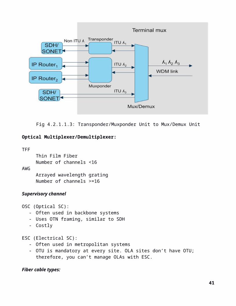
Fig 4.2.4.2.1: DWDM Hub and Satellite Ring Architecture
Candidate networks for DWDM application in the metropolitan area are often already based on SONET ring structures with 1 + 1 fiber protection. Thus protection schemes such as Unidirectional Path Switched Ring (UPSR) or Bidirectional Line Switched Ring (BLSR) can be reused for DWDM implementations. Figure 3-10 shows a UPSR scheme with two fibers. Here, hub and nodes send on two counter-rotating rings, but the same fiber is normally being used by all equipment to receive the signal; hence the name unidirectional. If the working ring should fail, the receiving equipment switches to the other pair. Although this provides full redundancy to the path, no bandwidth reuse is possible, as the redundant fiber must always be ready to carry the working traffic. This scheme is most commonly used in access networks.
41

Fig 4.2.4.2.2: UPSR Protection on a DWDM Ring
Other protection schemes, such as Bidirectional Line Switched Ring (BLSR), allow traffic to travel from the sending to the receiving node by the most direct route. Because of this, BLSR is considered preferable for core SONET networks, especially when implemented with four fibers, which offers complete redundancy.
8.3.Mesh Topologies
Mesh architectures are the future of optical networks. As networks evolve, rings and point-to-point architectures will still have a place, but mesh will be the most robust topology. This development will be enabled by the introduction of configurable optical cross-connects and switches that will in some cases replace and in other cases supplement fixed DWDM devices.From a design standpoint, there is a graceful evolutionary path available from point-to-point to mesh topologies. By beginning with point-to-point links, equipped with OADM nodes at the outset for flexibility, and subsequently interconnecting them, the network can evolve into a mesh without a complete redesign. Additionally, mesh and ring topologies can be joined by point-to-point links (see Figure 3-11).
Fig 4.2.4.3: Mesh, Point-to-Point, and Ring Architectures
DWDM mesh networks, consisting of interconnected all-optical nodes, will require the next generation of protection. Where previous protection schemes relied upon redundancy at the system, card, or fiber level, redundancy will now migrate to the wavelength level. This means, among other things, that a data channel might change wavelengths as it makes its way through the network, due either to routing or to a switch in wavelength because of a fault. The situation is analogous to that of a virtual circuit through an ATM cloud, which can experience changes in its virtual path identifier (VPI)/virtual channel identifier (VCI) values at switching points. In optical networks, this concept is sometimes called a light path. Mesh networks will therefore require a high degree of intelligence to perform the functions of protection and bandwidth management, including fiber and wavelength switching. The benefits in flexibility and efficiency, however, are potentially great. Fiber usage, which can be low in ring
42
solutions because of the requirement for protection fibers on each ring, can be improved in a mesh design. Protection and restoration can be based on shared paths, thereby requiring fewer fiber pairs for the same amount of traffic and not wasting unused wavelengths. Finally, mesh networks will be highly dependent upon software for management. A protocol based on Multiprotocol Label Switching (MPLS) is under development to support routed paths through an all-optical network. In addition, network management will require an as-yet unstandardized channel to carry messages among the network elements.
8.4.Single-Hop Networks vs Multi-hop Networks
Multi-wavelength networks can be also classified as single-hop networks and multi-hop networks. In single-hop networks, the data stream travels from source to destination as a light stream. There is no conversion to electronic form in any of the intermediate nodes. Two examples of single-hop networks are the broadcast-and-select and the wavelength-routed architecture.
Broadcast-and-select networks: It is based on a passive star coupler device connected to several nodes in a star topology. Basically a signal received on one port is split and broadcast to all ports. Networks are simple and have natural multicasting capabilities. Generally used in high speed LANs or MANs. Other elements in this type of network are tunable receivers and fixed transmitters or fixed receivers and tunable transmitters.
Wavelength routed networks: The key element here is the wavelength-selective switching subsystem. There are again two types of wavelength switching. Wavelength path switching involves dynamic signal switching
Network architectures are based on many factors, including types of applications and protocols, distances, usage and access patterns, and legacy network topologies. In the metropolitan market, for example, point-to-point topologies might be used for connecting enterprise locations, ring topologies for connecting inter-office facilities (IOFs) and for residential access, and mesh topologies might be used for inter-POP connections and connections to the long-haul backbone. In effect, the optical layer must be capable of supporting many topologies and, because of unpredictable developments in this area, those topologies must be flexible. Today, the main topologies in deployment are point-to-point and ring. With point-to-point links over DWDM between large enterprise sites, there needs only to be a customer premise device for converting application traffic to specific wavelengths and multiplexing. Carriers with linear-ring topologies can evolve toward full rings based on OADMs. As configurable optical cross-connects and switches become more common, these point-to-point and ring networks will be interconnected into meshes, transforming optical metropolitan networks into fully flexible platforms.
8.5.Ring Topology vs Mesh Topology
A ring topology is preferable owing to many of its capabilities. Unlike a mesh network, the expense of laying out the links is reduced in the ring, because the number of links increases only as a linear progression. The rings also have better resilience and restoration than meshes. The ring topology besides serving as a standby link helps share the load. The working segment (Refer to Fig.2) and the protection segment of the fiber together handle the large data burst of the computer network. This
43
reduces the load on the router and removes the need for buffering
Fig 4.2.4.5: Ring Topology Connecting Nodes A & B
44
2.2. Backhauling Small Cells in an LTE environment
9. Introduction
Heterogeneous Networks
Heterogeneous networks (HetNet) is a term used for modern mobile communications networks. A modern mobile communications network is comprised of a combination of different cell types and dif-ferent access technologies. A typical HetNet uses a combination of legacy systems (e.g. GSM en UMTS) and modern radio access technologies such as LTE, possibly completed with Wi-Fi.
One key challenge in HetNet is seamless micro base station introduction into a live network, as it can have a potentially adverse effect on key performance indicators (KPIs) such as drop rates due to macro-micro base station interference, so coordination is needed here. Micro base station deployment is necessary for macro base station offload in scenarios with numerous hotspots, but deployment re-quirements and costs for the former can be reduced by using solutions for flexible site backhaul and integrated power supply, feeders, and surge protection. With a large number of micro base stations in place, macro-micro base station O&M needs to be both consistent and easy, if costs are to be held in check.
9.1. Small cells
‘Small cells’ is an umbrella term for operator-controlled, low-powered radio access nodes, including those that operate in licensed spectrum and unlicensed carrier-grade Wi-Fi. Small cells typically have a range from 10 meters to several hundred meters.
Types of small cells include femtocells, picocells and microcells – broadly increasing in size from femtocells (the smallest) to microcells (the largest). Any or all of these small cells can be based on ‘femtocell technology’ – i.e. the collection of standards, software, open interfaces, chips and know-how that have powered the growth of femtocells.
Wireless backhaul for small cell is currently a fragmented market with no clear standard that promotes inter-vendor inter-operability. Proprietary solutions range from sub-6 GHz non-line-of-sight (NLOS) to 70 GHz E-Band line-of-sight (LOS). At the lower frequency bands, deployment is easier because of the NLOS multi-path and longer propagation paths. However this comes at the cost of limited bandwidth in congested spectrum that must be shared with access links.
Macro cellular networks, with cell radius 1- 30km Micro cellular networks, with cell radius 200 – 2000m Pico cellular networks, with cell radius 4 – 200m
Offering full compatibility with macro cells, small cells can be used to provide a second layer of coverage in 3G and LTE networks, resulting in higher throughput and data rates for the end- user, while improving performance at the cell’s edge. Small-cell stations use less energy than macro cells and have a far smaller physical footprint, allowing them to be easily hidden from view.
45
The edge link that connects micro cells to the rest of the network may use different technologies: wired (e.g., fiber) or wireless (e.g., LOS or NLOS; on licensed or licensed exempt spectrum; PTP or PMP). Bur it can also use different kind of traffic transport: namely, backhaul or fronthaul.
Fig 4.3.1.1: Small cell in a Macrocell layer
10.Why Small Cells
Driven by in-building wireless coverage requirements and the growing influx of mobile broadband data traffic, a traditional macrocell based cellular network deployment is not deemed to be a sufficient solution to address the coverage and capacity needs of today’s wireless subscribers. As a result, operators have begun to introduce small cells into their networks in order to keep up with demand. Costs are reduced as small cells circumvent the need to deploy cumbersome and expensive new base stations.
Small cells are primarily added to increase capacity in hot spots with high user demand and to fill areas not covered by macro network – both outdoors and indoors. They also improve network performance and service quality by offloading from large macro cells. The result is heterogeneous network with large macro cells in combination with small cells providing increased bit rates per unit area.
One way to expand an existing macro network, while maintaining it as a homogeneous network, is to ‘densify’ by adding more sectors per eNB or deploying more macro eNBs. However, reducing site-to-site distance in the macro network can only be pursued to a certain extent because finding new macro sites becomes increasingly difficult and can be expensive, especially in city centers. An alternative is to introduce small cells through the addition of low-power base station (eNB, HeNBs, RN [remote nodes], or RRH [radio relay heads]) to existing macro eNBs. Site acquisition is easier and cheaper with this equipment which is already correspondingly smaller.
46
A more general way to increase the capacity of a cellular system within the available spectrum is to create a layered/homogeneous network. Such a network has a micro-cell underlay to allow for greater spectrum reuse that provides greater capacity and an overlay of macro-cells that ensure continuity of the coverage between the micro-cells.
11.Backhaul or Fronthaul?Implications for performance
Mobile operators may choose between fronthaul and backhaul to transport traffic from the edge link from the micro cells to the mobile core network.
When using a backhaul architecture, an integrated micro cell (antenna, wireless transceiver, plus baseband) is connected to an aggregation point – i.e., a macro cell or other location that is connected (typically by fiber) to the mobile core. Because the micro cell processes the RAN traffic, the operator can use many solutions for backhaul, including fiber or other wire line technologies, or wireless links. Wireless links may include LOS and NLOS bands; PTP, PMP or mesh topologies; and licensed or license-exempt bands.
Fronthaul enables cloud-RAN (C-RAN) architecture, in which all the baseband units (BBUs) are located remote from the cell site. Fronthaul transports the unprocessed RF signal from the antennas to the remote BBUs. While fronthaul requires a higher bandwidth, lower latency and more accurate synchronization than backhaul, it enables a more efficient use of RAN resources, plus interference and mobility management tools, which can be particularly beneficial in HetNets that include a micro-cell layer.
Today, operators use C-RAN primarily in macro networks, where it increases the efficiency of network traffic management and resource utilization. C-RAN may bring even larger advantages in HetNets with micro cells, because micro and macro baseband colocation improves the efficacy of interference management tools such as CoMP and eICIC that are specifically designed for multilayer networks.
12.Challenges with small cell deployment and configuration
The backhaul for small cells is seen as the biggest challenge for small cell deployments. As the number of cell sites multiply to keep with capacity demand, so can the cost of the operator’s backhaul network. While fiber is widely used for macro-cell backhaul, many operators are suggesting that the high cost of fiber installation and leasing fees will kill the small cell business case. Instead, operators are estimating that 80% of the small cells will be connected with wireless backhaul [2]. This leads to the technological challenge of finding wireless solutions that provide enough spectrum in a cost effective manner, and that can sustain the expected continued growth in capacity.
With cellular phones becoming not just voice, but also data appliances, there is a growing need for operators to provide wide area (3-5mile) coverage that assures high-rate data and voice services in nearly every location. What used to be considered ‘acceptable’ gaps in coverage, are no longer areas that carriers can overlook.
Implementing smaller cell configurations raises new challenges for the mobile operator’s backhaul planning and operations teams. Whereas fixed-line backhaul solutions provide optimal capacity,
47

operators are generally limited by the lack of copper and fiber availability, as well as by the need to deploy base stations on telephone poles, lampposts, and other structures that limit wire line access. In cases like these, operators in need of quick deployments will generally choose wireless solutions in order to backhaul small-cell traffic. This section discusses the series of challenges faced by operators choosing to deploy small cells.
12.1. Bandwidth Provisioning From the backhaul perspective, small-cell backhaul traffic is generally lighter than that of macro cells, but traffic levels are expected to increase. Due to the concentration of users close to the site, the backhaul connection may quickly become the bottleneck. Current rule-of- thumb assumptions for picocell sites range from 50 Mbps to 100 Mbps. In addition, small cells will have to deal with a higher degree of burstiness than macro cells.
12.2. Availability and redundancy Small cells can provide capacity enhancement to an existing macrocell. In case of a malfunction in the small cell, the macrocell would still be able to maintain basic services. When small cells are deployed to enhance capacity within existing coverage, backhaul availability may be more relaxed than for macro cells.
12.3. Aggregation layerIncreased capacity and availability while enabling increased network capacity, small cell architectures increase capacity requirements from the backhaul network and may also require additional aggregation sites. Network operators should consider planning aggregation links of at least 1 Gbps, with scalability to 2 Gbps.
12.4. Small Footprint and Weight Smart integration of small cell sites into existing backhaul access points can help lower operator footprint. ‘Zero footprint’ designs are highly desirable for network operators, as they reduce both installation and site rental costs. Typical small cell sites should be suited for deployment atop street poles and traffic lights, or mountable on rooftops and walls, necessitating a small form factor for the whole cell site solution, including both the access and backhaul solutions. Weather-proofing is also required.
12.5. Backhaul Access Points The location of small cells vis-à-vis their backhaul connection points is an important consideration for operators. Locating the small cells nearer to subscribers makes access to backhaul hubs more difficult. While a high proportion of outdoor cells can be reached with LoS microwave links, many indoor links will require NLoS connections.
12.6. Dense Areas and Spectrum Availability While small-cell use improves capacity and availability, the increased cell density adds complexity to existing backhaul networks, as the proximity of cell sites creates possible interference issues. In
48
addition, spectrum reuse requires special attention as the deployment of small cells increases, as additional frequency pairs are added to the backhaul system.
12.7. Cost-effective Solution Significant cost reduction is required for the small cell backhaul network. Since many small cells are required to provide the coverage of a single macrocell, many new backhaul links must be deployed to carry their traffic. In order to maintain a targeted cost-per-bit, dramatic per-link savings must be accomplished. Operators can benefit here from the lower availability requirements of small cells, thanks to the higher reliability of existing macro cells. Small cell failure will reduce capacity, but will not result in service outages.
12.8. Other Requirements “Green” solutions – offering reduced power consumption. Flexible network architecture – backhauling infrastructure should be easily adaptable to chain,
ring, and point-to-multipoint topologies. Installation and commissioning – new station deployment should be quick and cost effective. Operation, administration and maintenance – similar to that of macrocells Scalability – traffic demand will double every year, but the exact locations of the increases may
not be known in advance. Backhaul solutions need to be scalable and flexible, in order to keep up with rapid traffic growth rates.
Packet based – for 4G and LTE-ready support.
13.Micro cell deployment
13.1. Taxonomy of Backhaul Solutions
Small-cell mobile backhaul transports traffic to an aggregation point in the same way that fiber or wire-less backhaul in the macro-cell layer does. Like in a macrocell, small-cell backhauls span across wired and wired options. The focus of this section is on wireless backhaul solutions. Fiber will make up only a minority of small-cell backhaul links since fiber is expensive both to install and to lease, if it is avail-able at all. Also performance requirements for small-cell backhaul can be met by both fiber and wire-less backhaul. Fiber availability, however, is crucial in small-cell deployments as this provides loca-tions for traffic aggregation points in the wireless backhaul system. The wireless backhaul options can generally be broken into line-of-sight (LOS), where a direct path through the air is required between the transmitter and receiver, and non-line-of-sight (NLOS), where diffraction, transmission and reflections are sufficient for signal propagation from transmitter to receiver.
49
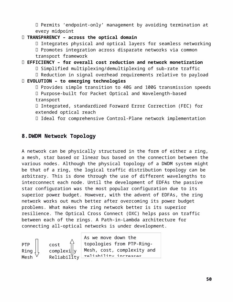
Fig 4.3.3.1: Taxonomy of Backhaul Solutions, with mmH additions in Red
13.2. Network Topology Options
The connectivity between the small cells and the aggregation point could be based on point-to-point, point-to-multipoint, or mesh topologies. Relative to the entire backhaul transport network, tree and branch architectures are typically used, as show in Figure 1-3, but in this paper we focus on the “last mile” connectivity for small cells. In point-to-point (PTP) technologies, there is a dedicated RF channel per link between the hub or aggregation point and the end-point. Also the hub or aggregation point has a dedicated radio and antenna for each PTP link. In point-to-multipoint (PMP) technologies, RF is shared across all PMP links. Also the hub or aggregation point has a shared radio antenna that is used across all PMP links at the aggregation point. As a further option, instead of connecting every single small cell to the macro site, chain, tree or mesh topologies can be used between the small cell sites to provide the required connectivity.
Near-LOS or even NLOS options can be considered when LOS solutions restrict backhaul coverage. There might be cases where specific small cell base stations cannot be directly connected to the macro cell site via a single wireless link because of physical obstructions, but can be reached via another small cell. In these cases more complex topologies like chains and mesh could be used. Such topologies would require the small cell backhaul solutions to support multiple wireless links as well as traffic ag-gregation. Connecting small cell base stations via chains or mesh may be an appropriate topology when they are installed on street furniture, e.g. lamp posts or other places where obstructions are common. In those cases it is sufficient that only one of the small cells is connected to the fiber network (e.g. via macro cell site) and further connectivity is provided among the small cell base stations themselves.
50
13.3. Existing Spectrum and Licensing Options
In this section we describe the spectrum options for small cell backhaul. Operators indicate an increasing focus on the sub 6 GHz and 60 GHz bands as the ones ideally suited to address small cells’ specific requirements in a NLOS and LOS environment, respectively. The prefer-ence for licensed operation in the sub-6 GHz frequencies is intuitive since interference from other net-works would be very difficult to manage, whereas in the 60 GHz band, interference without licensing is still quite manageable. TVWS (< 800MHz): TVWS channels offer good propagation properties, both in range and throughput or around obstacles. TVWS spectrum is unpaired and its channels are 6/7/8 MHz wide depending on the country. In locations where TVWS channel availability is high, TVWS spectrum can provide wire-less backhaul connections between small cells. The main risk with this spectrum is availability of TVWS channels and ability to provide guaranteed QoS requirements of small-cell backhaul.
Fig 4.3.3.3: Small-cell backhaul decision tree.
13.3.1.Fiber and wireless.
Unquestionably, fiber is the best solution for small-cell backhaul, so where it is available and cost ef-fective, it typically wins over wireless solutions. But it is not always available, and when it is, often it is
51
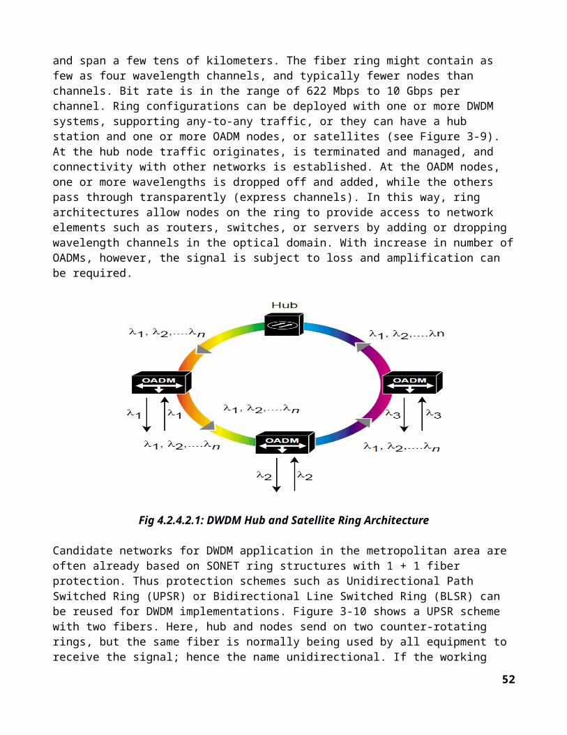
not cost effective, because either the installation costs (mostly due to trenching) or the operating costs (i.e., leasing costs) are too high. In many ways this is an easy decision point, mostly driven by how much an operator is willing to pay.
13.3.2.LOS and NLOS.
If the operator selects wireless backhaul, the choice among technologies becomes more complex, be-cause it depends on a larger number of factors, including spectrum and LOS availability, and capacity requirements (Figure 3). Other things being equal, operators prefer NLOS solutions in licensed spec-trum. But these solutions typically have less capacity and higher latency (especially in true NLOS con-ditions), and this makes them unsuitable for high-capacity small cells or for backhaul links that support multiple cells. In cases where 4G is combined with Wi-Fi or where operators share the backhaul link, capacity requirements grow quickly and operators are likely to select LOS solutions in the busiest loca-tions, with the addition of relays where there is a need to compensate for the lack of direct LOS.
Fig 4.3.3.3.2: LOS or NLOS
13.4. Technology and frequency recommendations.
52
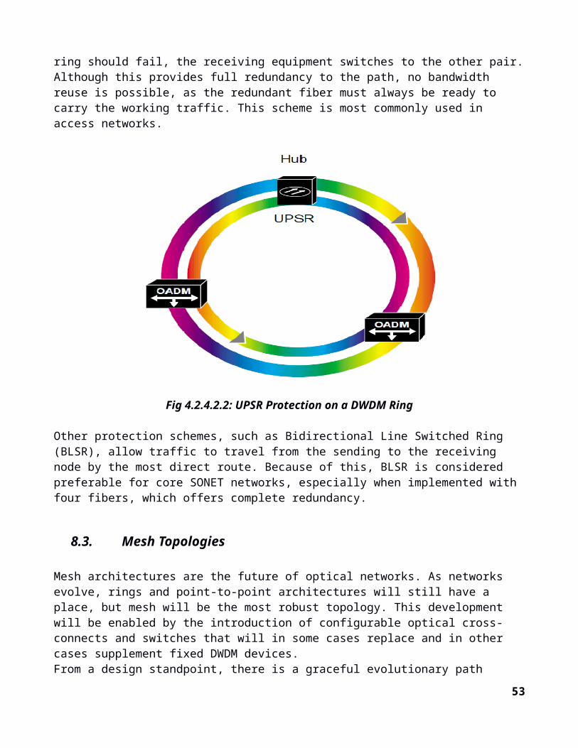
Sub-6 GHz licensed: Sub-6 GHz gives operators the flexibility to reach locations that are not within LOS. PMP architecture is the most common, but PTP can also be used. The downsides that severely re-strict adoption are that available bands in sub-6 GHz spectrum are scarce and expensive, and that they commonly come in narrow channels that have limited capacity, especially when used in a NLOS envi-ronment. The capacity limitations are compounded in a PMP architecture, where available capacity is shared among cells in the PMP network and frequency reuse is limited.
Sub-6 GHz unlicensed: In many areas, especially the dense urban areas that small cells target, interfer-ence in these intensely used bands is already high, thus discouraging further mobile operators from re-lying on these bands for backhaul. However, these bands offer a temporary or fallback solution to oper-ators that do not have access to sub-6 GHz licensed spectrum and have small cells with NLOS.
Microwave PTP/PMP: Microwave is by far the spectrum most commonly used for cellular backhaul but has very strong competition in the small-cell market because it combines some of the disadvantages of other bands without providing a unique benefit. Unlike sub-6 GHz bands, microwave requires LOS, but does not offer benefits of 60 GHz or E-band, such as smaller antennas, more capacity, and lower spectrum costs. Since microwave links can reach more-distant locations, they can be used in rural small-cell deployments or other locations where the small cell is far from the aggregation point. For metropolitan locations, the longer radius can become a liability, because it decreases the ability to reuse spectrum. In some bands and countries, regulatory requirements result in antenna sizes that are too large for small cells.
60 GHz: This is the unlicensed band that has attracted the highest interest among operators and back-haul vendors. The atmospheric and oxygen attenuation that makes the 60 GHz band not well suited to covering long-distance links is beneficial in a small-cell environment, where short range translates into less interference among adjacent links and, hence, greater spectrum reuse. The high frequency also al-lows for smaller antennas, which are a requirement for small-cell installations. However, LOS require-ments make it difficult to integrate the backhaul module within the small cell but relay links may be used to overcome LOS limitations. There are no channelization or antenna design requirements which increases the flexibility of solutions in this band, making it possible to reduce the antenna size and widen the beam width.
E-band (70-80GHz): Licenses in this band are inexpensive, but in most countries it is subject to tight regulations dictating specific antenna designs and channelization, which result in bigger antennas compared to the 60 GHz band. Regulatory changes are expected to remove these constraints in some markets, and will increase the attractiveness of this band for small-cell backhaul. In some countries, including the US, links are licensed and registered in a database, which means interference can be more effectively avoided or managed, thus protecting the operator’s investment in the backhaul equipment.
Another low cost approach for deploying the micro cell over a large area is via remote radio heads (RRH). In such a system, the lower level signal processing (baseband processing) is centralized. Base band data is digitally distributed to the remote radio heads placed at the desired locations, where it is then converted to/from RF and transmitted/received via antennas. As they do not require processing requirements of a normal cell site, remote radio heads are smaller than the typical macro cell deployment.
53
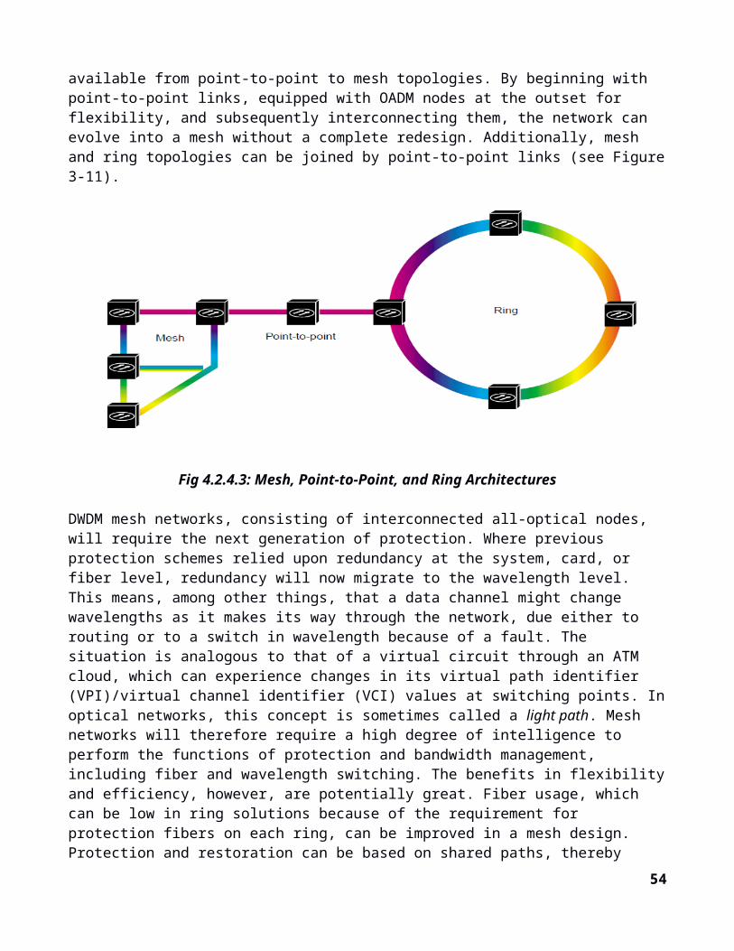
Fig 4.3.4: Technology and frequency recommendations
14.Solutions for best QoE.
One way to enable high QoE is to maintain coordination between radio nodes and layers – ensuring that operators maximize subscriber value (and revenue) per allocated spectrum. To implement this level of coordination, high-performance end-to-end backhaul in terms of speed, delay, and delay variation is recommended. To deliver maximum QoE across networks, operators should aim to build backhaul links with high performance – such as LOS microwave and optical links – building out from the macrocells whenever possible. Where no fixed links are available, wireless is the natural choice, as it enables short time to market and more freedom of site placement. For an even greater degree of freedom, high-per-forming NLOS microwave links may be used.
To support multi-standard radio deployments – where, for example, WCDMA, LTE and Wi-Fi traffic share backhaul – the backhaul solution will need QoS functionality. This functionality then needs to be aligned with the radio solution to give operators control over system performance in the event of back-haul overload or link degradation.
The following table describes the most common locations for placement of small cell stations:
Cell Type Backhaul Access PointsMacro Tower top (or bottom), rooftop
Micro – metro Mostly outdoor, utility pole, wall, roof
Pico / Femto – outdoor Street fixtures, rooftops, walls, overhead cables, utility poles
54
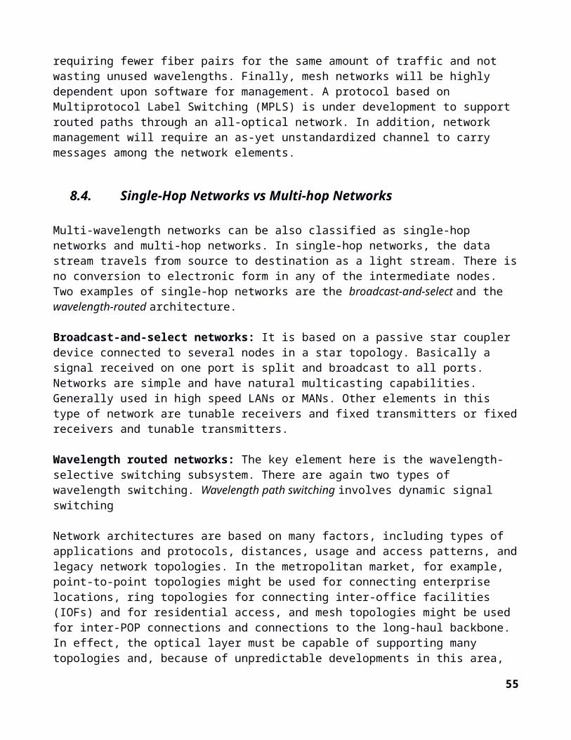
Pico / Femto – indoor Backhaul to the building, then use internal wiring or backhaul direct to the small cells
Femto – enterprise Office, factory, shop, café
Femto – consumer Home
Table 3: Summary of Small Cell locations placement.
The following table provides a brief summary of small cell backhauling requirements:
Backhaul Requirement
Compared to Macrocells
Notes
Cost Cheaper Cost per link should be lower. Cost per bit may be similar.
Capacity Traffic load is lighter but burstier Small cells generate less backhaul traffic than multi-cell/mode/band macrocells, but the traffic is much burstier.
Scalability More scalable Faster growth requires rapid deployment despite shorter lead times.
Latency More delay tolerant Delay sensitivity depends on service level expectations. Femtocells are designed to cope with lower quality connections. Femtocell handover is less important.
Availability “Five Nines” not needed Small cells will form an offload underlay to a higher-availability macrocell.
Size & Weight Smaller and lighter stations Small cells require deployment in locations with limited space availability. Compact backhauling solution is essential.
Access to Backhaul More difficult Small cells are close to users – on the street and indoors, relatively far from backhaul sites. These sites are harder to reach than tower-based macrocells.
Installation & Commissioning Faster, simpler, cheaper Consumer femtocells are plug-and-play. Femtocell backhauling should also work this way.
55
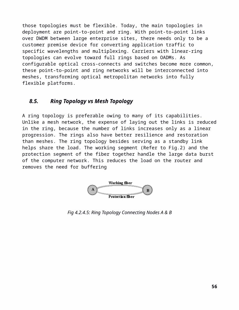
Table 4: Summary of Small Cell Requirements (Source NGMN)
14.1. Overview of Solutions for Small Cell Backhaul
In this section, we introduce small cell backhauling solutions, and show how they meet most aspects of the challenges described above.The following backhaul solutions for small-cell deployments are currently available on the market: Traditional microwave (6-42 GHz) Sub 6 GHz microwave – either point-to-point or point-to-multipoint “Light” licensed millimeter wave (E-band) microwave (70-80 GHz) Unlicensed millimeter wave (60 GHz) Copper wire xDSL Fiber optics Free space optics Cable / DOCSIS
We assume that every technology is best suited for specific scenarios, and that multiple solutions will be used on any given operator network.
Table 3 (below) highlights the capabilities of each of the small-cell backhauling solutions:
mm Wave 60 GHz
E-Band 70-80 GHz
Point-to-Point Sub- 6 GHz
Point-to-MultiPoint Sub- 6 GHz
Main pros Unlicensed, higher capacity, high frequency re-use factor
Inexpensive license, higher capacity
Both LoS and NLoS solutions
Enables high peaks to individual cells without needing to overprovision Easier Installations – CPE only
Main cons Requires LoS, very short links
Requires LoS Licensed sub 6 GHz: Expensive, medium capacity
Unlicensed sub 6 GHz: Medium capacity
Hub and spoke configuration only
Backhaul topology is more limited
Capacity Multi Gbps 1.2 Gbps 200 Mbps Aggregated 200 Mbps Aggregated
Backhaul licensing
Unlicensed Light License Licensed (3.5 GHz) / Unlicensed
Licensed (3.5 GHz) / Unlicensed
Line of Sight LoS only LoS only LoS / NLoS LoS / NLoS
Backhaul network topology
Chain, Ring (PtP) Chain, Ring (PtP)
Chain, ring (PtP) Hub and spoke (PtMP)
56

Installation Type Street poles / rooftop / wall / traffic light...
L2 switching capability
N/A Yes
Terminal power consumption
N/A 20W 15W 20W
Table 5: Wireless Backhaul Alternatives for Small Cells
15.Market Requirements
When considering the total cost of ownership for backhaul systems, numerous publications converge around the position that point to point systems (PTP) do not make financial sense with increasing small cell density. Instead, business case studies are suggesting that point to multipoint (PMP) systems are at a financial advantage. Additionally, these studies commonly point out that fiber is generally more expensive than wireless because of the high cost of laying the fiber. Hence, fiber solutions may not be suitable for the small cell business case, and even if deployed with sufficient density, there may not be sufficient access to it. Existing fiber deployments may not be made available to all small cell operators due to competitive business positions.
From the various references mentioned above, the general consensus is that PMP systems have lower TCO than PTP systems because of the following:
Where licensing is required, spectrum is licensed by region in frequencies typically used by PMP systems whereas spectrum is typically licensed per link in frequencies typically used by PTP systems. Therefore, PMP licensing costs do not increase with growing cell densities.
By the very nature of LOS propagation, PTP systems are more difficult to plan and install, thus driving up deployment cost.
PTP systems require more equipment. For example, when each link is added to the system, a highly directional antenna and transceiver is added to each end of the link regardless of what equipment is already present.
The difference in TCO between NLOS and LOS options for PMP systems is driven by equipment and installation costs. Based on today’s technology being evaluated in these studies, PMP-LOS systems require costly installation to point antennas in the correct direction and generally require installations at both ends of the link. PMP-NLOS systems on the other hand benefit from propagation characteristics making locating sites, positioning and installation easier. Additionally, the cost of PMP-NLOS systems can be nearly 35% less than PMP LOS systems.
15.1. TCO Considerations
Built fiber has the highest CAPEX, as is it expensive to deploy, especially in the high density urban areas where operators plan to install most microcells. But it is cheapest to operate, because no fiber leasing or spectrum license is necessary. Fiber installation will account for about 80% of the CAPEX of the 60GHz backhaul solution.
57
A higher percentage of backhaul TCO in small cells than in macro cells.
Because of the differences in requirements, the percentage of RAN TCO accounted for by small-cell backhaul is approximately twice that accounted for by macro cells (Figure 1). The emergence of cost-effective solutions is going to be crucial to establishing a solid business case for smallcell backhaul. Without cost-effective solutions, it is difficult to see how extensive small-cell deployments can be rolled out, especially at a time when mobile operators face severe financial pressures.
Coexistence of multiple solutions.
Although many operators have a preference for one backhaul technology over others, they agree that no single technology can meet all the backhaul requirements. We have developed a decision tree (Figure 2) that summarizes how different technologies may be deployed. While it is not prescriptive, the graph il-lustrates the complexity of the decision process that the operator has to go through for each small cell.
15.2. Value Proposition
Access to 6 GHz of bandwidth – No License Required: Each channel is ~2GHz. Three channels available in most of the world.
Noise Limited Operation – Better than having a licensed sub-6 GHz band: Highly directional an-tennas, nulling, and atmospheric losses imply low interference.
No New Fiber: Existing fiber PoP density is sufficient. Small cells grow out from existing eNode B lo-cations.
Flexible topology: Directional multi-hop mesh eliminates the need for direct (and longer) links be-tween small-cells and aggregation point/macro-cell. Provides flexibility in topology by using LOS links to immediate small-cell neighbors instead of LOS requirement to the aggregation point.
Scalability: New small-cell nodes can be added with minimal backhaul planning.
Flexible and Auto-configuration: Electrically steerable antennas allow auto discovery and creation of new links and nodes.
Low Cost Sites and Installation: Less than ½ hr installation time on street furniture with minimally trained installer.
Built-in Robustness: Redundancy through mesh, which also provides load balancing and deployment flexibility.
Distributed directional-mesh MAC: A fully distributed scheduled, multi-hop and TDM based direc-tional mesh MAC to ensure fast scheduling and minimal queuing delay.
Full-Duplex: Full-duplex operation achieved by spatial separation of Tx and Rx.
Low-latency: Layer 2 forwarding/routing coupled with joint scheduling and routing allow for a low-la-tency mesh-backhaul.
Low Cost Nodes: Leveraging the consumer electronics market for antennas, radios, and baseband pro-cessing.
58
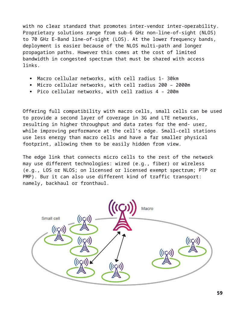
Single baseband and RF processing chain: Avoids multiple baseband and RF processing chains (as used in traditional-mesh) by using electronically steerable antennas and TDM-based MAC to develop a low-cost solution.
Integrated Access Link/Backhaul Hardware: Flexibility to provide integrated backhaul module to be added to small-cell enclosure; enabled by electronically steerable antenna and automatic discovery. Use of beam-steering antennas to support self-configuration (reduced deployment costs)
16.Small cell Conclusion
Small-cell rollout strategies vary across mobile operators, and so do the backhaul strategies, as the ca-pacity, functionality and reliability constraints change. In this context, the mobile operators’ ability to choose from a wide array of solutions is critical to enabling all of them, regardless of their backhaul strategy and requirements, to find the right mix of solutions. Since small cell networks grow over time, self-organizing backhaul networks are needed. With a large amount of mobile data traffic generated in-doors, small cell deployment may rely on fiber and copper when deployed indoors. When indoor, cop-per and fiber become an important part of the solution, but when outdoor, there are a multitude of tech-nologies from E-band, to millimeter wavelengths, to sub 6GHz solutions with LOS and NLOS.
Backhaul availability determines the feasible placements of cells, and impacts installation costs and the time needed for site acquisition and installation. When deploying a new radio site, operators will need a well-defined variety of backhaul options and combinations of complementary technologies to meet the business case. Adopting a holistic perspective when evolving today’s networks to heterogeneous net-works will help operators address network evolution efficiently.
A combination of both sub 6GHz and E-band can be used for downlink and uplink respectively to better utilize the capacity. Overall, the backhaul should not limit the RAN and should have sufficient end-to-end performance to meet to meet the desired user QoE everywhere.
There is no one solution that fixes all, when it comes to small cell deployments. We will have to look into each scenario and selectively on a case by case basis use any or a combination of these technolo-gies to provide the best solution for the network.
Improve existing macro cells – by enhancing macro cells with more spectrum, advance antennae, increased order of diversification on the receiver and/or the transmitter, the baseband processing capacity within and between nodes. Continued evolution of HSPA and LTE technology will drive macro network efficiency through specialized features, such as high-order modulation, high sectorization, and multi-carrier and multi- antenna solutions, as well as using hybrid radio solutions. Increasing capacity and data rates this way does not require new sites.
Densify the macro network – the capacity and data rates achieved by enhancing the macro network alone, will eventually be insufficient to meet demand. The targeted addition of cells strategically located can improve capacity. This approach keeps the total number of sites relatively low, while network performance becomes less sensitive to traffic location. A simply way to densify a network could be a cell-split which enables a site from transitioning to a six-sector from a three sector site. These strategic cells could macro equipment, or even micro equipment.
59
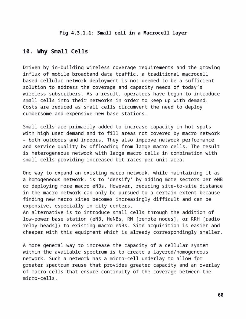
Add small cells – by complementing macro cells with small cells and dedicated indoor solutions, based on the 3GPP standard. This approach can include the use of micro cells, pico cells or low power remote radio units (RRUs), as well as Wi-Fi. It delivers high per user capacity and rate coverage in areas covered by the small cells, with the potential to improve performance in the macro network by offloading traffic generated in hotspots. The degree of the integration that can be achieved throughout the heterogeneous network will determine the overall network performance.
Existing PTP solutions that use mmW have costs that scale per link, rather than per cell, which be-comes prohibitive with interconnected small cells. Existing NLOS PMP solutions operate at lower fre-quencies where spectrum is limited and interference is a challenge. With an mmW PMP backhaul using electrically steerable antennas, we can enable the deployment and cost advantages of sub-6 GHz PMP NLOS backhaul systems while providing higher capacity using millimeter wave frequencies.
Deployment solutions should solve the long term capacity growth problems beginning with backhaul for the small cell, and later introducing mmW access link technology. Backhaul solutions will require up to 1 Gbps data links in small cell clusters. Spacing between these cells will range from 50 to 200 meters. A small cell mesh backhaul using mmW bands will result in a scalable and cost effective solution for long term growth of very high capacity small cells.In conclusion, microcells are a main way to decrease the capacity of cellular networks. Their wide deployment is enabled by their size and ease of installation.
Complexity from a multi-vendor, multi-technology backhaul approach.
Mobile operators will have to deploy multiple backhaul solutions to reach all their small. To do so, they can choose a single vendor that offers multiple solutions and can manage all backhaul with tools provided by the vendor. In most cases, however, we expect operators to use more than one backhaul vendor within the same footprint. Within a metro area, an operator may have fiber plus a NLOS and a LOS wireless solution, each with its own capacity, latency and functionality. Operators gain flexibility from adopting multiple solutions, but they pay a price in managing a backhaul architecture that has grown more complex. Interoperability and partnerships among vendors and their network management tools will also play a prominent role in enabling small-cell deployments and in coordinating transmission within the wider mobile network.
16.1. SUPPORTING THE BUSINESS CASE
Deploying a vast number of new small cells highlights the need for cost-efficient solutions thatSupport the overall business case. The chosen backhaul solution must not be costly to plan for,Install, operate or maintain. It must match the anticipated volume of data traffic that the site willHave to handle, as well as support the network performance required. Developing mobile backhaul options that can serve any site location will maximize return on investment for existing sites and active equipment – this is particularly important for small cells that have limited reach and may serve a small percentage of an operator’s subscriber base. Different sites will pose different challenges. Having the flexibility to choose between dedicated high-performance backhaul and the reuse of existing resources on site will be essential to support short time to market at the right cost. This is easier said than done, and it will be increasingly difficult to achieve without a holistic approach to radio, backhaul and installation services.
60

Consumers are demanding ubiquitous mobile services—especially bandwidth-hungry data services—and there is no doubt that this trend will continue to accelerate. Therefore, service providers are in the process of enhancing their mobile networks to support this massive growth. One of the most challenging tasks in designing such a solution is planning a cost-effective backhaul for those new locations.
Planning the optimal solution must take the following considerations into account:• Small cells will require hundreds of megabits backhaul capacity.• Solution must support the macro cellular quality-of-service (QoS) scheme.• Synchronization (SyncE/iEEE 1588v2) capabilities are essential.• Protected topology must be supported from day one, even though the protection scheme may be enabled later.• Multiple physical UNi are required for:
- Multiple service delivery at the same location- Enabling back-to-back connectivity
• Solution needs to have low power consumption with multiple feeding options.• Solution should enable easy and fast deployment procedures.
As the performance of these backhaul networks is now even more important than before, then perfor-mance monitoring capabilities become important to ensure the Service Level Agreement (SLA) is met. This applies both internally within network operators and also in the wholesale scenario where a third party operator provides all or some of the backhaul connection. Overall, any next generation mobile backhaul solution that is intended to support LTE-A needs provide outstanding transport performance and also maintain or enhance the cost-per-bit economics of the net-work.
61
3. Conclusion
3.1. Experience summary
I acquired knowledge, skills and met new people. Achieved several of my learning goals and performed well in certain tasks that came my way, with high accuracy. I now have insight into professional practices, different facets of working within the industry. I noticed financing, as in many organizations, is an important factor for the progress of projects. It made me define what skills and knowledge I have to improve on.
Project Deployment challenges Operators can’t keep up with the rapid introduction of new technology while continuously
expanding network capacity With high complexity and sheer volume of tasks, operators cannot meet their delivery time, cost
and quality targets.
Limitations of today's planning tools and processes
Lack of end-to-end orchestration across multiple systems and organizational groups. Inability to scale effectively across the network. Lack of agility to handle in-flight project changes Lack of centralized information for network resources – (single source of truth). Lack of integrated technical design
3.2.Recommendations
Recommendations for the company.MTNC is an innovative company well suited for interns. It provides interns with a good platform on improving and developing their skills. I would recommend MTNC to keep hiring interns with different educational background, to help build and improve the company's standards with the experience gained from young and enthusiastic interns.
The presentation of the researches carried out will be available upon request. Backhauling Small cells Fiber System Dense Wave Division Multiplexing (DWDM) Synchronous Digital Network (SDH)
62
References
1. https://www.google.cm/
63
GlossaryADMadd-drop multiplexerANSIAmerican National Standards InstituteATMasynchronous transfer mode; a form of fast short packet switching andmultiplexingAUadministrative unit; a managed entity within the SDH structureBISDNbroadband integrated services digital networkCCITTComité Consultif International de Telegraphique et Telephonique; in English,Consultative Committee on International Telegraphy and Telephony; predecessorof ITU–TSDCCdata communications channel; the main management channel inside SDHDCSdigital cross-connect system; an electronic multiport switch for digital trafficDXCdigital cross-connect; see DCSETSIEuropean Telecommunications Standards InstituteFDDIfiber distributed data interface; a short range 100 Mbps interface used betweenlarge computing nodesIDLCintegrated digital loop carrier; a North American system for connecting anexchange/central office to subscribers over a large area via fiberIPInternet protocol; a component of protocol for many computer links includingthe InternetITU–TSInternational Telecommunications Union–Transmission StandardsLANlocal-area network; a linked group of computersMANmetropolitan-area network; an area network for public broadband trafficNNInetwork node interface; a defined interface between nodes in the public networkPDHplesiochronous digital hierarchy; the widely deployed transmission system whichpredates SDHPOHpath overhead; a group of management communications facilities in SDHSDHsynchronous digital hierarchy
64
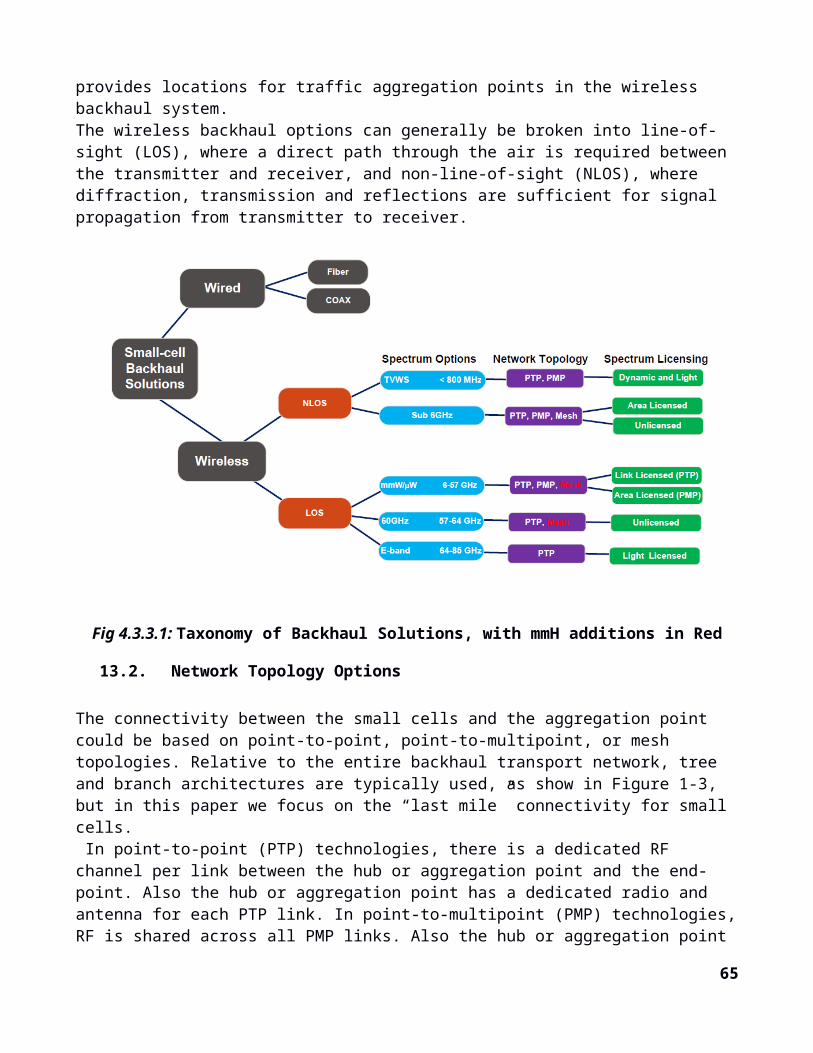
SOHsection overhead; a group of management communications facilities in SDHSONETsynchronous optical network; the North American variant of SDHSTMsynchronous transport module; the basic unit of transmission in SDHTUtributary unit; the basic unit of payload together with its management overheadsand synchronization dataTUGtributary unit group; a managed group of TUUNIuser-network interface; a defined interface between the user and the publicnetworkVCvirtual container; the basic unit of payload together with its managementoverheads
65