SB_27_1199_02 service buletin
69
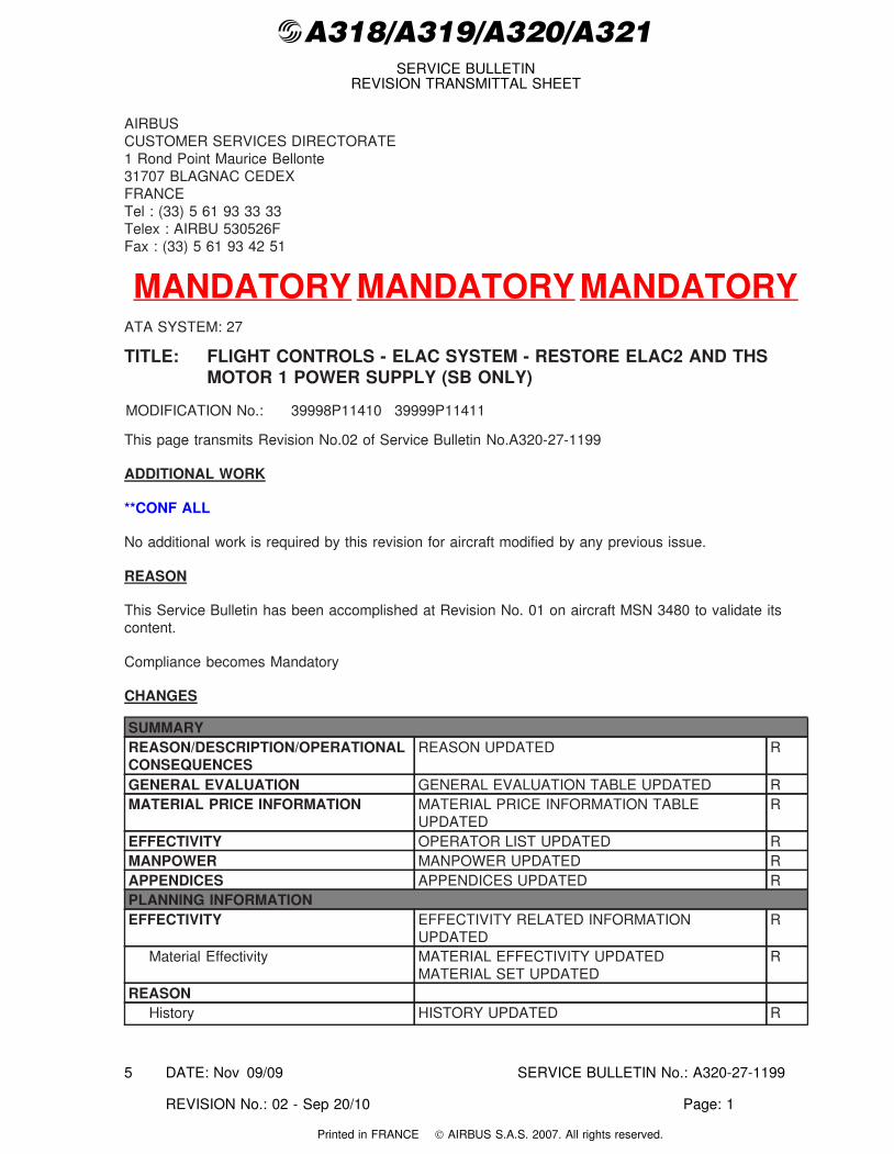
@A318/A319/A320/A321 SERVICE BULLETIN REVISION TRANSMITTAL SHEET AIRBUS CUSTOMER SERVICES DIRECTORATE 1 Rond Point Maurice Bellonte 31707 BLAGNAC CEDEX FRANCE Tel : (33) 5 61 93 33 33 Telex : AIRBU 530526F Fax : (33) 5 61 93 42 51 MANDATORY MANDATORY MANDATORY ATA SYSTEM: 27 TITLE: FLIGHT CONTROLS - ELAC SYSTEM - RESTORE ELAC2 AND THS MOTOR 1 POWER SUPPLY (SB ONLY) MODIFICATION No.: 39998P11410 39999P11411 This page transmits Revision No.02 of Service Bulletin No.A320-27-1199 ADDITIONAL WORK **CONF ALL No additional work is required by this revision for aircraft modified by any previous issue. REASON This Service Bulletin has been accomplished at Revision No. 01 on aircraft MSN 3480 to validate its content. Compliance becomes Mandatory CHANGES SUMMARY REASON/DESCRIPTION/OPERATIONAL CONSEQUENCES REASON UPDATED R GENERAL EVALUATION GENERAL EVALUATION TABLE UPDATED R MATERIAL PRICE INFORMATION MATERIAL PRICE INFORMATION TABLE UPDATED R EFFECTIVITY OPERATOR LIST UPDATED R MANPOWER MANPOWER UPDATED R APPENDICES APPENDICES UPDATED R PLANNING INFORMATION EFFECTIVITY EFFECTIVITY RELATED INFORMATION UPDATED R Material Effectivity MATERIAL EFFECTIVITY UPDATED MATERIAL SET UPDATED R REASON History HISTORY UPDATED R DATE: Nov 09/09 SERVICE BULLETIN No.: A320-27-1199 REVISION No.: 02 - Sep 20/10 Page: 1 5 Printed in FRANCE © AIRBUS S.A.S. 2007. All rights reserved.
-
Upload
kerol-mansor -
Category
Documents
-
view
245 -
download
10
description
aircraft service buletin
Transcript of SB_27_1199_02 service buletin
@A318/A319/A320/A321SERVICE BULLETIN
REVISION TRANSMITTAL SHEET
AIRBUSCUSTOMER SERVICES DIRECTORATE1 Rond Point Maurice Bellonte31707 BLAGNAC CEDEXFRANCETel : (33) 5 61 93 33 33Telex : AIRBU 530526FFax : (33) 5 61 93 42 51
MANDATORY MANDATORY MANDATORYATA SYSTEM: 27
TITLE: FLIGHT CONTROLS - ELAC SYSTEM - RESTORE ELAC2 AND THSMOTOR 1 POWER SUPPLY (SB ONLY)
MODIFICATION No.: 39998P11410 39999P11411
This page transmits Revision No.02 of Service Bulletin No.A320-27-1199
ADDITIONAL WORK
**CONF ALL
No additional work is required by this revision for aircraft modified by any previous issue.
REASON
This Service Bulletin has been accomplished at Revision No. 01 on aircraft MSN 3480 to validate itscontent.
Compliance becomes Mandatory
CHANGES
SUMMARYREASON/DESCRIPTION/OPERATIONALCONSEQUENCES
REASON UPDATED R
GENERAL EVALUATION GENERAL EVALUATION TABLE UPDATED RMATERIAL PRICE INFORMATION MATERIAL PRICE INFORMATION TABLE
UPDATEDR
EFFECTIVITY OPERATOR LIST UPDATED RMANPOWER MANPOWER UPDATED RAPPENDICES APPENDICES UPDATED RPLANNING INFORMATIONEFFECTIVITY EFFECTIVITY RELATED INFORMATION
UPDATEDR
Material Effectivity MATERIAL EFFECTIVITY UPDATEDMATERIAL SET UPDATED
R
REASONHistory HISTORY UPDATED R
DATE: Nov 09/09 SERVICE BULLETIN No.: A320-27-1199
REVISION No.: 02 - Sep 20/10 Page: 1
5
Printed in FRANCE © AIRBUS S.A.S. 2007. All rights reserved.
@A318/A319/A320/A321SERVICE BULLETIN
REVISION TRANSMITTAL SHEET
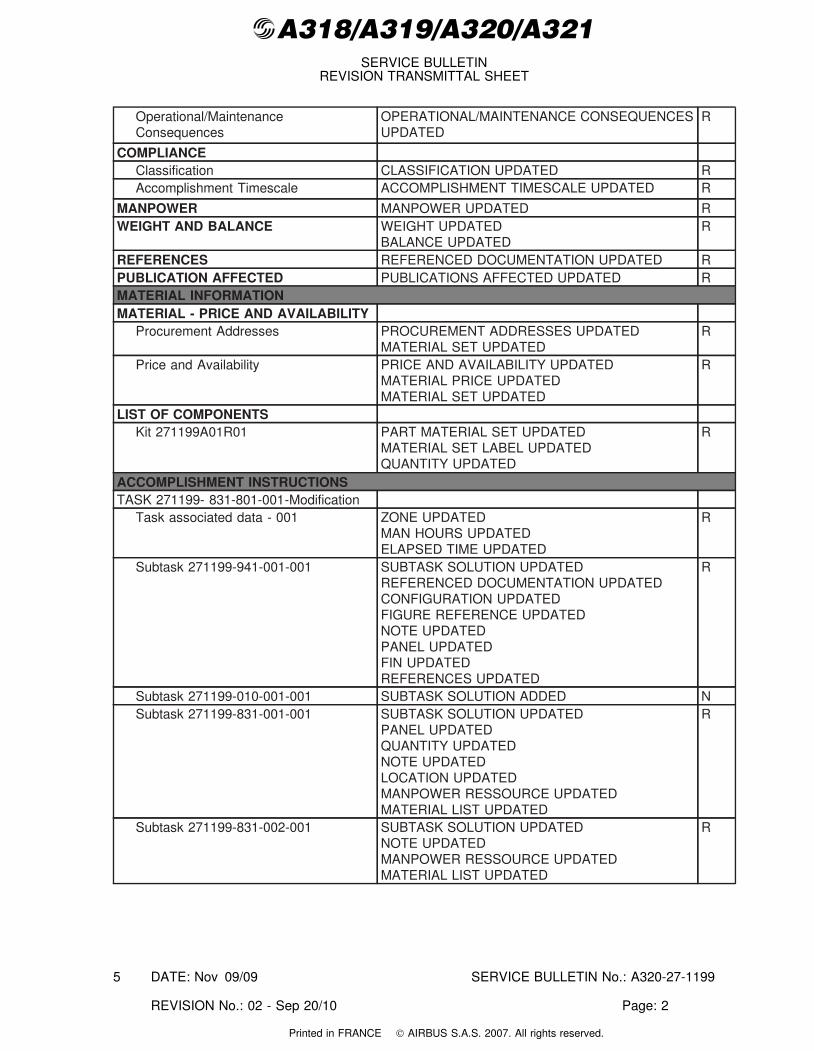
Operational/MaintenanceConsequences
OPERATIONAL/MAINTENANCE CONSEQUENCESUPDATED
R
COMPLIANCEClassification CLASSIFICATION UPDATED RAccomplishment Timescale ACCOMPLISHMENT TIMESCALE UPDATED R
MANPOWER MANPOWER UPDATED RWEIGHT AND BALANCE WEIGHT UPDATED
BALANCE UPDATEDR
REFERENCES REFERENCED DOCUMENTATION UPDATED RPUBLICATION AFFECTED PUBLICATIONS AFFECTED UPDATED RMATERIAL INFORMATIONMATERIAL - PRICE AND AVAILABILITY
Procurement Addresses PROCUREMENT ADDRESSES UPDATEDMATERIAL SET UPDATED
R
Price and Availability PRICE AND AVAILABILITY UPDATEDMATERIAL PRICE UPDATEDMATERIAL SET UPDATED
R
LIST OF COMPONENTSKit 271199A01R01 PART MATERIAL SET UPDATED
MATERIAL SET LABEL UPDATEDQUANTITY UPDATED
R
ACCOMPLISHMENT INSTRUCTIONSTASK 271199- 831-801-001-Modification
Task associated data - 001 ZONE UPDATEDMAN HOURS UPDATEDELAPSED TIME UPDATED
R
Subtask 271199-941-001-001 SUBTASK SOLUTION UPDATEDREFERENCED DOCUMENTATION UPDATEDCONFIGURATION UPDATEDFIGURE REFERENCE UPDATEDNOTE UPDATEDPANEL UPDATEDFIN UPDATEDREFERENCES UPDATED
R
Subtask 271199-010-001-001 SUBTASK SOLUTION ADDED NSubtask 271199-831-001-001 SUBTASK SOLUTION UPDATED
PANEL UPDATEDQUANTITY UPDATEDNOTE UPDATEDLOCATION UPDATEDMANPOWER RESSOURCE UPDATEDMATERIAL LIST UPDATED
R
Subtask 271199-831-002-001 SUBTASK SOLUTION UPDATEDNOTE UPDATEDMANPOWER RESSOURCE UPDATEDMATERIAL LIST UPDATED
R
DATE: Nov 09/09 SERVICE BULLETIN No.: A320-27-1199
REVISION No.: 02 - Sep 20/10 Page: 2
5
Printed in FRANCE © AIRBUS S.A.S. 2007. All rights reserved.
@A318/A319/A320/A321SERVICE BULLETIN
REVISION TRANSMITTAL SHEET
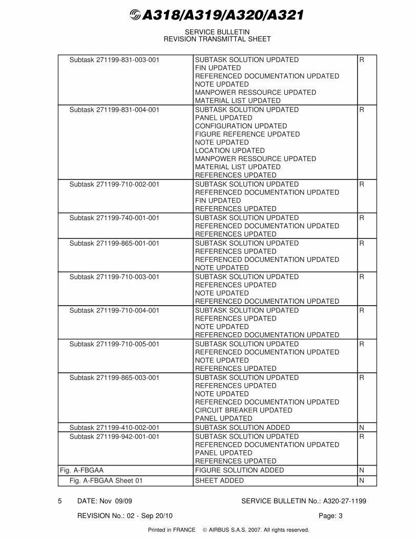
Subtask 271199-831-003-001 SUBTASK SOLUTION UPDATEDFIN UPDATEDREFERENCED DOCUMENTATION UPDATEDNOTE UPDATEDMANPOWER RESSOURCE UPDATEDMATERIAL LIST UPDATED
R
Subtask 271199-831-004-001 SUBTASK SOLUTION UPDATEDPANEL UPDATEDCONFIGURATION UPDATEDFIGURE REFERENCE UPDATEDNOTE UPDATEDLOCATION UPDATEDMANPOWER RESSOURCE UPDATEDMATERIAL LIST UPDATEDREFERENCES UPDATED
R
Subtask 271199-710-002-001 SUBTASK SOLUTION UPDATEDREFERENCED DOCUMENTATION UPDATEDFIN UPDATEDREFERENCES UPDATED
R
Subtask 271199-740-001-001 SUBTASK SOLUTION UPDATEDREFERENCED DOCUMENTATION UPDATEDREFERENCES UPDATED
R
Subtask 271199-865-001-001 SUBTASK SOLUTION UPDATEDREFERENCES UPDATEDREFERENCED DOCUMENTATION UPDATEDNOTE UPDATED
R
Subtask 271199-710-003-001 SUBTASK SOLUTION UPDATEDREFERENCES UPDATEDNOTE UPDATEDREFERENCED DOCUMENTATION UPDATED
R
Subtask 271199-710-004-001 SUBTASK SOLUTION UPDATEDREFERENCES UPDATEDNOTE UPDATEDREFERENCED DOCUMENTATION UPDATED
R
Subtask 271199-710-005-001 SUBTASK SOLUTION UPDATEDREFERENCED DOCUMENTATION UPDATEDNOTE UPDATEDREFERENCES UPDATED
R
Subtask 271199-865-003-001 SUBTASK SOLUTION UPDATEDREFERENCES UPDATEDNOTE UPDATEDREFERENCED DOCUMENTATION UPDATEDCIRCUIT BREAKER UPDATEDPANEL UPDATED
R
Subtask 271199-410-002-001 SUBTASK SOLUTION ADDED NSubtask 271199-942-001-001 SUBTASK SOLUTION UPDATED
REFERENCED DOCUMENTATION UPDATEDPANEL UPDATEDREFERENCES UPDATED
R
Fig. A-FBGAA FIGURE SOLUTION ADDED N
Fig. A-FBGAA Sheet 01 SHEET ADDED N
DATE: Nov 09/09 SERVICE BULLETIN No.: A320-27-1199
REVISION No.: 02 - Sep 20/10 Page: 3
5
Printed in FRANCE © AIRBUS S.A.S. 2007. All rights reserved.
@A318/A319/A320/A321SERVICE BULLETIN
REVISION TRANSMITTAL SHEET
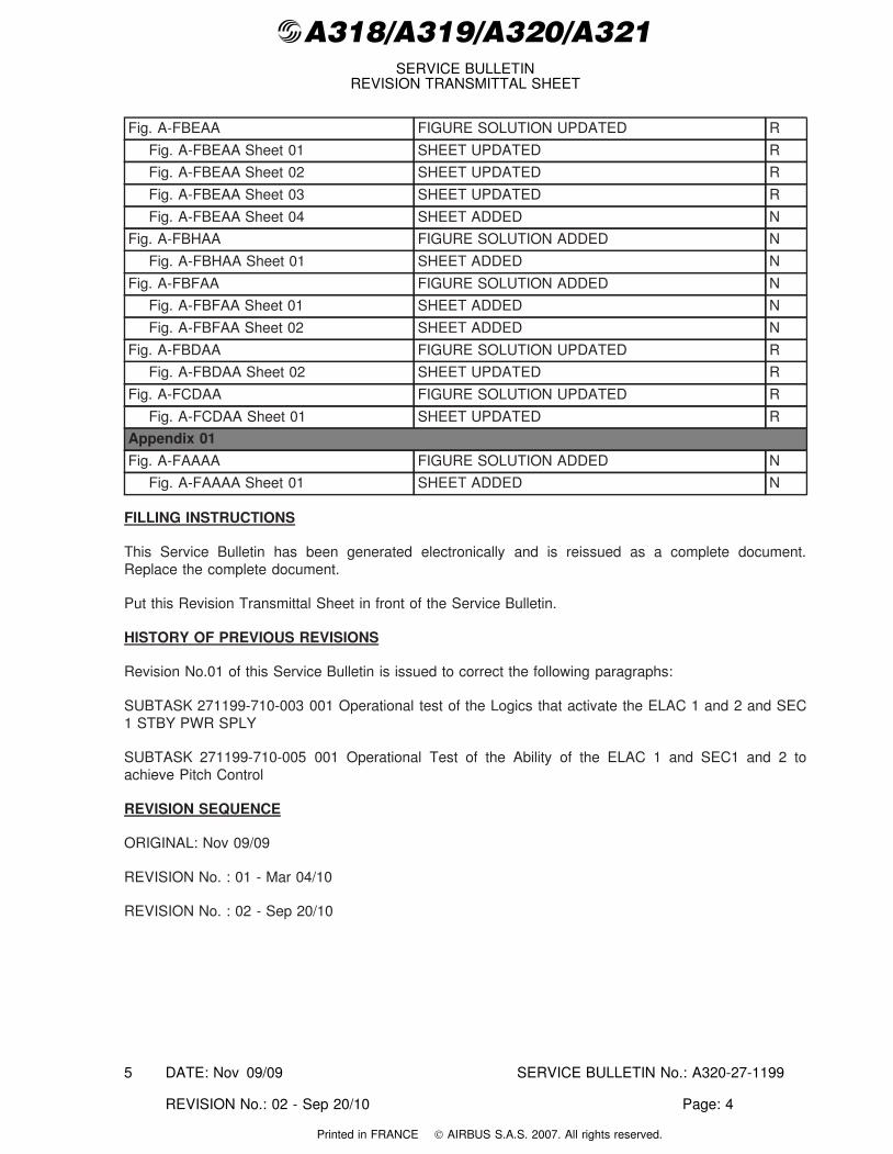
Fig. A-FBEAA FIGURE SOLUTION UPDATED R
Fig. A-FBEAA Sheet 01 SHEET UPDATED R
Fig. A-FBEAA Sheet 02 SHEET UPDATED R
Fig. A-FBEAA Sheet 03 SHEET UPDATED R
Fig. A-FBEAA Sheet 04 SHEET ADDED N
Fig. A-FBHAA FIGURE SOLUTION ADDED N
Fig. A-FBHAA Sheet 01 SHEET ADDED N
Fig. A-FBFAA FIGURE SOLUTION ADDED N
Fig. A-FBFAA Sheet 01 SHEET ADDED N
Fig. A-FBFAA Sheet 02 SHEET ADDED N
Fig. A-FBDAA FIGURE SOLUTION UPDATED R
Fig. A-FBDAA Sheet 02 SHEET UPDATED R
Fig. A-FCDAA FIGURE SOLUTION UPDATED R
Fig. A-FCDAA Sheet 01 SHEET UPDATED R
Appendix 01
Fig. A-FAAAA FIGURE SOLUTION ADDED N
Fig. A-FAAAA Sheet 01 SHEET ADDED N
FILLING INSTRUCTIONS
This Service Bulletin has been generated electronically and is reissued as a complete document.Replace the complete document.
Put this Revision Transmittal Sheet in front of the Service Bulletin.
HISTORY OF PREVIOUS REVISIONS
Revision No.01 of this Service Bulletin is issued to correct the following paragraphs:
SUBTASK 271199-710-003 001 Operational test of the Logics that activate the ELAC 1 and 2 and SEC1 STBY PWR SPLY
SUBTASK 271199-710-005 001 Operational Test of the Ability of the ELAC 1 and SEC1 and 2 toachieve Pitch Control
REVISION SEQUENCE
ORIGINAL: Nov 09/09
REVISION No. : 01 - Mar 04/10
REVISION No. : 02 - Sep 20/10
DATE: Nov 09/09 SERVICE BULLETIN No.: A320-27-1199
REVISION No.: 02 - Sep 20/10 Page: 4
5
Printed in FRANCE © AIRBUS S.A.S. 2007. All rights reserved.
@A318/A319/A320/A321SERVICE BULLETIN
SUMMARY
AIRBUSCUSTOMER SERVICES DIRECTORATE1 Rond Point Maurice Bellonte31707 BLAGNAC CEDEXFRANCETel : (33) 5 61 93 33 33Telex : AIRBU 530526FFax : (33) 5 61 93 42 51
This summary is for information only and is not approved for modification of the aircraft.
MANDATORY MANDATORY MANDATORYATA SYSTEM: 27
TITLE: FLIGHT CONTROLS - ELAC SYSTEM - RESTORE ELAC2 AND THSMOTOR 1 POWER SUPPLY (SB ONLY)
**CONF ALL
MODIFICATIONS
MODIFICATION CLASSIFICATIONMAJOR NoneMINOR 39998P11410 39999P11411
NOTE: As per EASA IR 21, a minor change is one that has no appreciable effect on themass, balance, structural strength, reliability, operational characteristics affecting theairworthiness of the product. All other changes are major changes.
REASON/DESCRIPTION/OPERATIONAL CONSEQUENCES
This Service Bulletin is published for all operators of A320 aircraft.
Under emergency electrical configuration (electrical power achieved by emergency electrical generatorCSMG (Constant Speed Motor Generator) driven by the RAT (Ram Air Turbine)), only ELAC1 andSEC1 are operative among the Flight Control computer.
In the original design of the Single Aisle (SA) A/C family, the RAT was not efficient enough with NLGextended to provide Blue hydraulic pressure and to energize the emergency electrical generator CSMG.
In order to provide better aircraft controllability and redundancy, a set of wiring and relays was installedto energize the ELAC2 and THS Motor 1 through the battery under emergency electrical configurationas soon the NLG is extended. Taking benefit of the enhanced RAT installed later on SA aircraft,the ELAC2 and THS Motor 1 supply logic has been simplified. Logic has been simplified and isno more activated when NLG is extended. This has been introduced by Mod. No. 38310P10576(FLIGHT CONTROLS -ELAC SYSTEM - IMPROVE ELECTRICAL INSTALLATION OF ELAC2 ANDTHS MOTOR 1 POWER SUPPLY) in 2007. This modification aimed at removing temporized relays44CE, 46CE and 64CE (which embed electronic devices that make them more fragile), thus improvingthe ELAC2 and THS Motor 1 supply logic robustness.
DATE: Nov 09/09 SERVICE BULLETIN No.: A320-27-1199
REVISION No.: 02 - Sep 20/10 Page: 1
5
Printed in FRANCE © AIRBUS S.A.S. 2007. All rights reserved.

@A318/A319/A320/A321SERVICE BULLETIN
SUMMARY
However, it has been identified that this modification affects the roll controllability in case of emergencyelectrical configuration combined with a dual G +Y hydraulic loss. In this extremely remote situation, onA320 aircraft, the roll control would be only provided by the left aileron with landing gear extended.
This Service Bulletin recommends to restore the aircraft configuration before the application of the Mod.No. 38310P10576.
This modification will permit, in case of an emergency electrical configuration combined with a dual G+Y hydraulic loss arises on the A320 aircraft, to restore the availability of the right aileron upon landinggear extension.
Accomplishment of this Service Bulletin implies some changes in the procedure given in AMM Task27-96-00-710-018 that is called as per MPD 27-90-00 (400FH or 80DY). Until the AMM is accordinglyupdated (after the SB Reporting Sheet receipt and AMM update processing), Airbus ask operatorsto use the testing procedure embedded in this Service Bulletin at SUBTASK 271199-710-003 001Operational test of the Logics that activate the ELAC 1 and 2 and SEC 1 STBY PWR SPLY .
GENERAL EVALUATION
EVALUATION TABLECOMPLIANCE MANDATORY (1) CANCELS INSPECTION SB NO
POTENTIAL AD YES A/C OPERATION AFFECTED NORELIABILITY AFFECTED NO PAX COMFORT AFFECTED NOCOST SAVING NO ETOPS AFFECTED NOSTRUCTURAL LIFE EXTN NO VENDOR SB INVOLVED NO
NOTE (1): Service Bulletin must be accomplished.
MATERIAL PRICE INFORMATION
MATERIAL PRICE INFORMATION TABLEMATERIAL SET QTY PER
A/CPRICE PERA/C (USD)
MAIN PARTS
Kit 271199A01R01 1 3,370.00 Bundle, relays
EFFECTIVITY
This Service Bulletin is applicable to this (these) operator(s) :
62X AAR ABY ADH AEE AFL AFR AIJ AVA AXM AZA BAW BHPCCA CEB CES CSC CSZ DKH EIN FFT IGO JBU JST KNE KZRLAN LBT LTU MDL PAL RNV SBI TAI TAM VLG VRD WAU WZZ
CONCURRENT REQUIREMENTS
None
REFERENCES / REPERCUSSIONS
TFU NoneOEB NoneAOT NoneSIL None
DATE: Nov 09/09 SERVICE BULLETIN No.: A320-27-1199
REVISION No.: 02 - Sep 20/10 Page: 2
5
Printed in FRANCE © AIRBUS S.A.S. 2007. All rights reserved.
@A318/A319/A320/A321SERVICE BULLETIN
SUMMARY
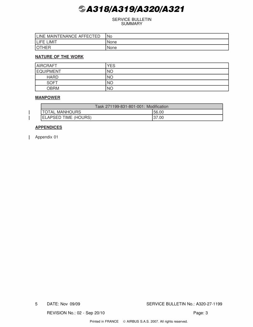
LINE MAINTENANCE AFFECTED NoLIFE LIMIT NoneOTHER None
NATURE OF THE WORK
AIRCRAFT YESEQUIPMENT NO
HARD NOSOFT NOOBRM NO
MANPOWER
Task 271199-831-801-001: ModificationTOTAL MANHOURS 56.00ELAPSED TIME (HOURS) 37.00
APPENDICES
Appendix 01
DATE: Nov 09/09 SERVICE BULLETIN No.: A320-27-1199
REVISION No.: 02 - Sep 20/10 Page: 3
5
Printed in FRANCE © AIRBUS S.A.S. 2007. All rights reserved.
@A318/A319/A320/A321SERVICE BULLETIN
SUMMARY
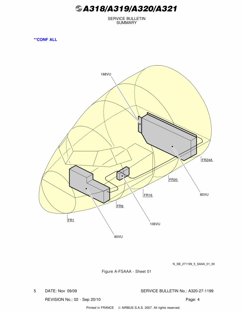
**CONF ALL
FR1
FR9
FR16
FR20
FR24A
80VU
90VU
106VU
188VU
N_SB_271199_5_SAAA_01_00
Figure A-FSAAA - Sheet 01
DATE: Nov 09/09 SERVICE BULLETIN No.: A320-27-1199
REVISION No.: 02 - Sep 20/10 Page: 4
5
Printed in FRANCE © AIRBUS S.A.S. 2007. All rights reserved.
@A318/A319/A320/A321SERVICE BULLETIN
AIRBUSCUSTOMER SERVICES DIRECTORATE1 Rond Point Maurice Bellonte31707 BLAGNAC CEDEXFRANCETel : (33) 5 61 93 33 33Telex : AIRBU 530526FFax : (33) 5 61 93 42 51
MANDATORY MANDATORY MANDATORYATA SYSTEM: 27
TITLE: FLIGHT CONTROLS - ELAC SYSTEM - RESTORE ELAC2 AND THSMOTOR 1 POWER SUPPLY (SB ONLY)
MODIFICATION No.: 39998P11410 39999P11411
This document contains AIRBUS PROPRIETARY INFORMATION and shall at all times remain theproperty of AIRBUS; no intellectual property right or licence is granted by AIRBUS in connection withany information contained in it. It is delivered on the express condition that said document and theinformation contained in it shall be treated as confidential, shall not be used for any purpose other thanthat for which it is hereby delivered. It shall not be disclosed in whole or in part to third parties and shallnot be duplicated in any manner (except for the purposes of performing the tasks described hereunderand provided that any recipient of such document shall comply with the conditions herein), withoutAIRBUS prior written consent.
1. PLANNING INFORMATION
**CONF ALL
A. EFFECTIVITY
NOTE: This modification is applicable by Service Bulletin only.
NOTE: This Service Bulletin has been validated on A320 aircraft MSN3480.
NOTE: This Service Bulletin is only applicable on Aircraft on which Mod.No. 38310P10576 (FLIGHT CONTROLS - ELAC SYSTEM IMPROVEELECTRICAL INSTALLATION OF ELAC2 AND THS MOTOR 1 POWERSUPPLY) is embodied.
(1) Models
320-214 320-216 320-232 320-233
(2) Effectivity by MSN
3391-3392 3394 3396 3398 3400 3402 3404 3408-3410 3412 3414 3416 3418 34203422-3423 3425 3427 3430-3431 3433 3435 3437 3439-3440 3444 3446 3448-34493451 3453 3455-3457 3460-3461 3464-3465 3468 3470 3472-3490 3492 3494-34973499 3501-3503 3505-3506 3508 3510-3511 3514-3517 3519 3521 3524 35263528-3529 3531-3532 3535-3536 3538 3540-3541 3543 3545 3547 3549-35503553-3554
DATE: Nov 09/09 SERVICE BULLETIN No.: A320-27-1199
REVISION No.: 02 - Sep 20/10 Page: 1
5
Printed in FRANCE © AIRBUS S.A.S. 2007. All rights reserved.
@A318/A319/A320/A321SERVICE BULLETIN
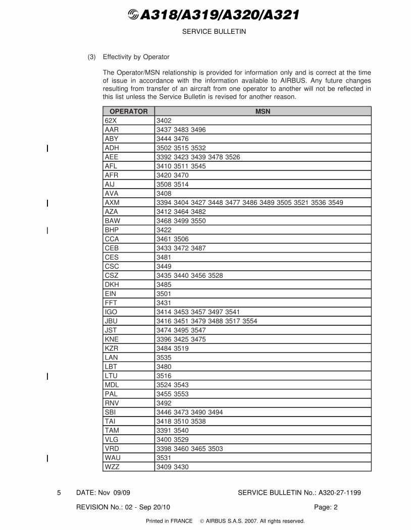
(3) Effectivity by Operator
The Operator/MSN relationship is provided for information only and is correct at the timeof issue in accordance with the information available to AIRBUS. Any future changesresulting from transfer of an aircraft from one operator to another will not be reflected inthis list unless the Service Bulletin is revised for another reason.
OPERATOR MSN62X 3402AAR 3437 3483 3496ABY 3444 3476ADH 3502 3515 3532AEE 3392 3423 3439 3478 3526AFL 3410 3511 3545AFR 3420 3470AIJ 3508 3514AVA 3408AXM 3394 3404 3427 3448 3477 3486 3489 3505 3521 3536 3549AZA 3412 3464 3482BAW 3468 3499 3550BHP 3422CCA 3461 3506CEB 3433 3472 3487CES 3481CSC 3449CSZ 3435 3440 3456 3528DKH 3485EIN 3501FFT 3431IGO 3414 3453 3457 3497 3541JBU 3416 3451 3479 3488 3517 3554JST 3474 3495 3547KNE 3396 3425 3475KZR 3484 3519LAN 3535LBT 3480LTU 3516MDL 3524 3543PAL 3455 3553RNV 3492SBI 3446 3473 3490 3494TAI 3418 3510 3538TAM 3391 3540VLG 3400 3529VRD 3398 3460 3465 3503WAU 3531WZZ 3409 3430
DATE: Nov 09/09 SERVICE BULLETIN No.: A320-27-1199
REVISION No.: 02 - Sep 20/10 Page: 2
5
Printed in FRANCE © AIRBUS S.A.S. 2007. All rights reserved.
@A318/A319/A320/A321SERVICE BULLETIN
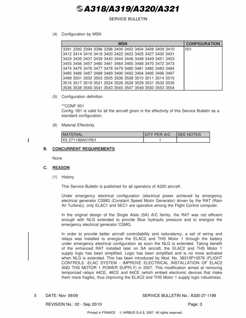
(4) Configuration by MSN
MSN CONFIGURATION3391 3392 3394 3396 3398 3400 3402 3404 3408 3409 34103412 3414 3416 3418 3420 3422 3423 3425 3427 3430 34313433 3435 3437 3439 3440 3444 3446 3448 3449 3451 34533455 3456 3457 3460 3461 3464 3465 3468 3470 3472 34733474 3475 3476 3477 3478 3479 3480 3481 3482 3483 34843485 3486 3487 3488 3489 3490 3492 3494 3495 3496 34973499 3501 3502 3503 3505 3506 3508 3510 3511 3514 35153516 3517 3519 3521 3524 3526 3528 3529 3531 3532 35353536 3538 3540 3541 3543 3545 3547 3549 3550 3553 3554
001
(5) Configuration definition
**CONF 001Config. 001 is valid for all the aircraft given in the effectivity of this Service Bulletin as astandard configuration.
(6) Material Effectivity
MATERIAL QTY PER A/C SEE NOTESKit 271199A01R01 1
B. CONCURRENT REQUIREMENTS
None
C. REASON
(1) History
This Service Bulletin is published for all operators of A320 aircraft.
Under emergency electrical configuration (electrical power achieved by emergencyelectrical generator CSMG (Constant Speed Motor Generator) driven by the RAT (RamAir Turbine)), only ELAC1 and SEC1 are operative among the Flight Control computer.
In the original design of the Single Aisle (SA) A/C family, the RAT was not efficientenough with NLG extended to provide Blue hydraulic pressure and to energize theemergency electrical generator CSMG.
In order to provide better aircraft controllability and redundancy, a set of wiring andrelays was installed to energize the ELAC2 and THS Motor 1 through the batteryunder emergency electrical configuration as soon the NLG is extended. Taking benefitof the enhanced RAT installed later on SA aircraft, the ELAC2 and THS Motor 1supply logic has been simplified. Logic has been simplified and is no more activatedwhen NLG is extended. This has been introduced by Mod. No. 38310P10576 (FLIGHTCONTROLS -ELAC SYSTEM - IMPROVE ELECTRICAL INSTALLATION OF ELAC2AND THS MOTOR 1 POWER SUPPLY) in 2007. This modification aimed at removingtemporized relays 44CE, 46CE and 64CE (which embed electronic devices that makethem more fragile), thus improving the ELAC2 and THS Motor 1 supply logic robustness.
DATE: Nov 09/09 SERVICE BULLETIN No.: A320-27-1199
REVISION No.: 02 - Sep 20/10 Page: 3
5
Printed in FRANCE © AIRBUS S.A.S. 2007. All rights reserved.
@A318/A319/A320/A321SERVICE BULLETIN
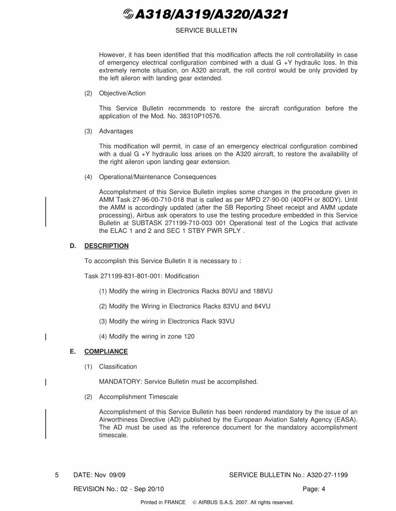
However, it has been identified that this modification affects the roll controllability in caseof emergency electrical configuration combined with a dual G +Y hydraulic loss. In thisextremely remote situation, on A320 aircraft, the roll control would be only provided bythe left aileron with landing gear extended.
(2) Objective/Action
This Service Bulletin recommends to restore the aircraft configuration before theapplication of the Mod. No. 38310P10576.
(3) Advantages
This modification will permit, in case of an emergency electrical configuration combinedwith a dual G +Y hydraulic loss arises on the A320 aircraft, to restore the availability ofthe right aileron upon landing gear extension.
(4) Operational/Maintenance Consequences
Accomplishment of this Service Bulletin implies some changes in the procedure given inAMM Task 27-96-00-710-018 that is called as per MPD 27-90-00 (400FH or 80DY). Untilthe AMM is accordingly updated (after the SB Reporting Sheet receipt and AMM updateprocessing), Airbus ask operators to use the testing procedure embedded in this ServiceBulletin at SUBTASK 271199-710-003 001 Operational test of the Logics that activatethe ELAC 1 and 2 and SEC 1 STBY PWR SPLY .
D. DESCRIPTION
To accomplish this Service Bulletin it is necessary to :
Task 271199-831-801-001: Modification
(1) Modify the wiring in Electronics Racks 80VU and 188VU
(2) Modify the Wiring in Electronics Racks 83VU and 84VU
(3) Modify the wiring in Electronics Rack 93VU
(4) Modify the wiring in zone 120
E. COMPLIANCE
(1) Classification
MANDATORY: Service Bulletin must be accomplished.
(2) Accomplishment Timescale
Accomplishment of this Service Bulletin has been rendered mandatory by the issue of anAirworthiness Directive (AD) published by the European Aviation Safety Agency (EASA).The AD must be used as the reference document for the mandatory accomplishmenttimescale.
DATE: Nov 09/09 SERVICE BULLETIN No.: A320-27-1199
REVISION No.: 02 - Sep 20/10 Page: 4
5
Printed in FRANCE © AIRBUS S.A.S. 2007. All rights reserved.
@A318/A319/A320/A321SERVICE BULLETIN
F. APPROVAL
Approved under EASA Design Organisation Approval No. EASA 21J.031.
If an aircraft listed in the effectivity has a modification or repair embodied that is not ofAIRBUS origin, and which affects the content of this Service Bulletin, the operator isresponsible for obtaining approval by its airworthiness authority for any adaptation necessarybefore incorporation of the Service Bulletin.
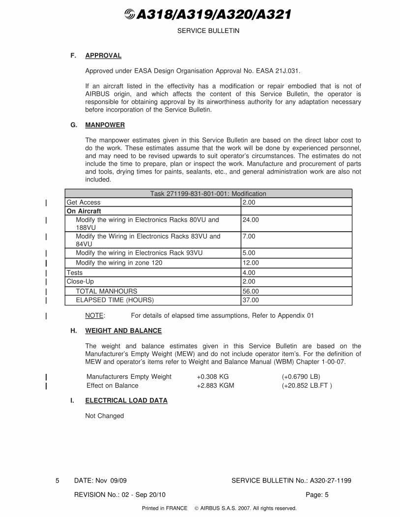
G. MANPOWER
The manpower estimates given in this Service Bulletin are based on the direct labor cost todo the work. These estimates assume that the work will be done by experienced personnel,and may need to be revised upwards to suit operator’s circumstances. The estimates do notinclude the time to prepare, plan or inspect the work. Manufacture and procurement of partsand tools, drying times for paints, sealants, etc., and general administration work are also notincluded.
Task 271199-831-801-001: ModificationGet Access 2.00On Aircraft
Modify the wiring in Electronics Racks 80VU and188VU
24.00
Modify the Wiring in Electronics Racks 83VU and84VU
7.00
Modify the wiring in Electronics Rack 93VU 5.00
Modify the wiring in zone 120 12.00
Tests 4.00Close-Up 2.00
TOTAL MANHOURS 56.00ELAPSED TIME (HOURS) 37.00
NOTE: For details of elapsed time assumptions, Refer to Appendix 01
H. WEIGHT AND BALANCE
The weight and balance estimates given in this Service Bulletin are based on theManufacturer’s Empty Weight (MEW) and do not include operator item’s. For the definition ofMEW and operator’s items refer to Weight and Balance Manual (WBM) Chapter 1-00-07.
Manufacturers Empty Weight +0.308 KG (+0.6790 LB)Effect on Balance +2.883 KGM (+20.852 LB.FT )
I. ELECTRICAL LOAD DATA
Not Changed
DATE: Nov 09/09 SERVICE BULLETIN No.: A320-27-1199
REVISION No.: 02 - Sep 20/10 Page: 5
5
Printed in FRANCE © AIRBUS S.A.S. 2007. All rights reserved.
@A318/A319/A320/A321SERVICE BULLETIN
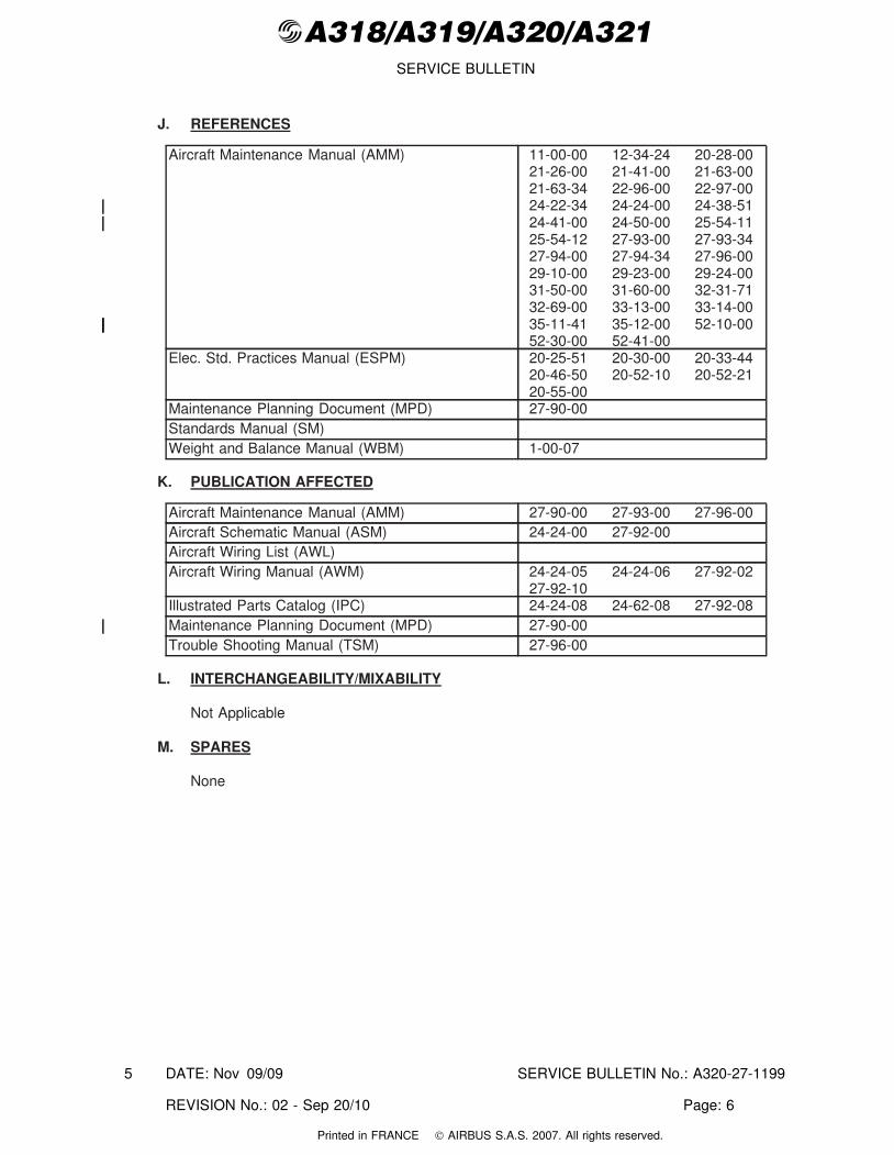
J. REFERENCES
Aircraft Maintenance Manual (AMM) 11-00-00 12-34-24 20-28-0021-26-00 21-41-00 21-63-0021-63-34 22-96-00 22-97-0024-22-34 24-24-00 24-38-5124-41-00 24-50-00 25-54-1125-54-12 27-93-00 27-93-3427-94-00 27-94-34 27-96-0029-10-00 29-23-00 29-24-0031-50-00 31-60-00 32-31-7132-69-00 33-13-00 33-14-0035-11-41 35-12-00 52-10-0052-30-00 52-41-00
Elec. Std. Practices Manual (ESPM) 20-25-51 20-30-00 20-33-4420-46-50 20-52-10 20-52-2120-55-00
Maintenance Planning Document (MPD) 27-90-00Standards Manual (SM)Weight and Balance Manual (WBM) 1-00-07
K. PUBLICATION AFFECTED
Aircraft Maintenance Manual (AMM) 27-90-00 27-93-00 27-96-00Aircraft Schematic Manual (ASM) 24-24-00 27-92-00Aircraft Wiring List (AWL)Aircraft Wiring Manual (AWM) 24-24-05 24-24-06 27-92-02
27-92-10Illustrated Parts Catalog (IPC) 24-24-08 24-62-08 27-92-08Maintenance Planning Document (MPD) 27-90-00Trouble Shooting Manual (TSM) 27-96-00
L. INTERCHANGEABILITY/MIXABILITY
Not Applicable
M. SPARES
None
DATE: Nov 09/09 SERVICE BULLETIN No.: A320-27-1199
REVISION No.: 02 - Sep 20/10 Page: 6
5
Printed in FRANCE © AIRBUS S.A.S. 2007. All rights reserved.
@A318/A319/A320/A321SERVICE BULLETIN
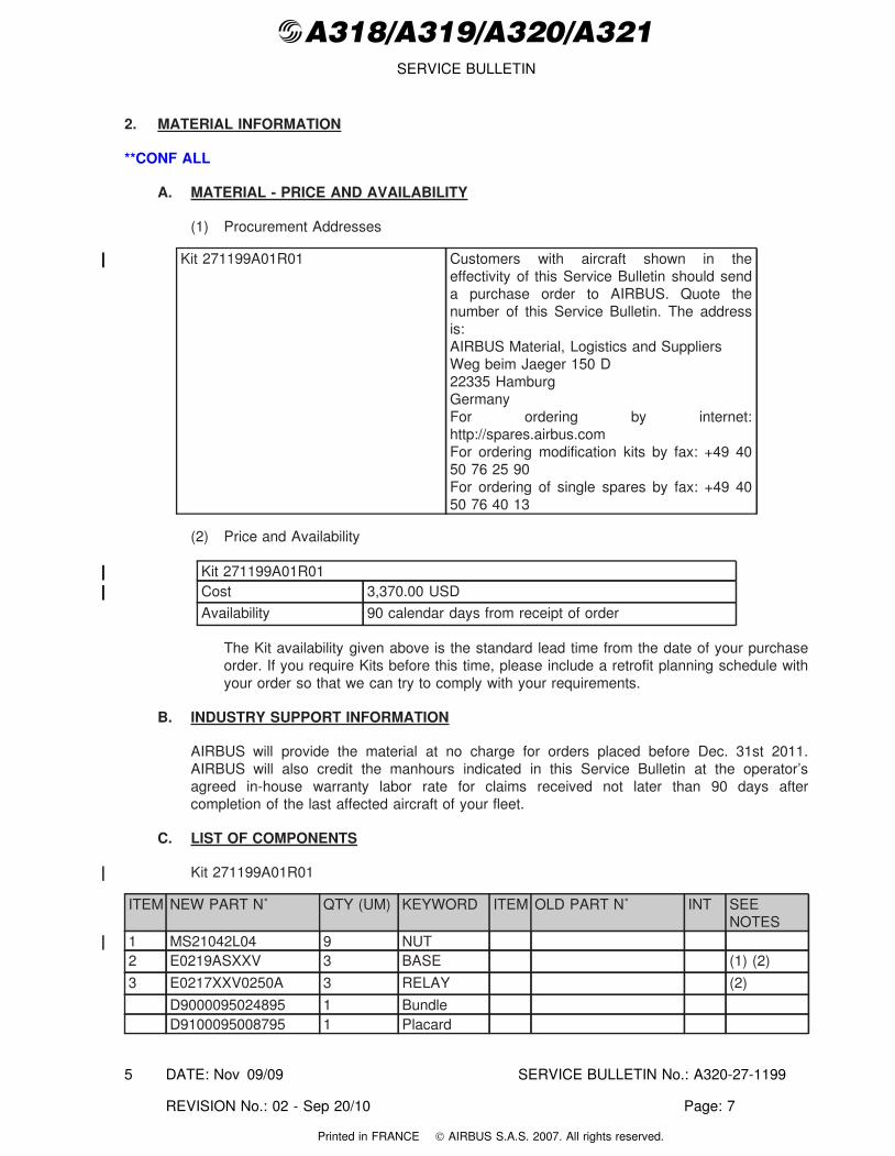
2. MATERIAL INFORMATION
**CONF ALL
A. MATERIAL - PRICE AND AVAILABILITY
(1) Procurement Addresses
Kit 271199A01R01 Customers with aircraft shown in theeffectivity of this Service Bulletin should senda purchase order to AIRBUS. Quote thenumber of this Service Bulletin. The addressis:AIRBUS Material, Logistics and SuppliersWeg beim Jaeger 150 D22335 HamburgGermanyFor ordering by internet:http://spares.airbus.comFor ordering modification kits by fax: +49 4050 76 25 90For ordering of single spares by fax: +49 4050 76 40 13
(2) Price and Availability
Kit 271199A01R01Cost 3,370.00 USD
Availability 90 calendar days from receipt of order
The Kit availability given above is the standard lead time from the date of your purchaseorder. If you require Kits before this time, please include a retrofit planning schedule withyour order so that we can try to comply with your requirements.
B. INDUSTRY SUPPORT INFORMATION
AIRBUS will provide the material at no charge for orders placed before Dec. 31st 2011.AIRBUS will also credit the manhours indicated in this Service Bulletin at the operator’sagreed in-house warranty labor rate for claims received not later than 90 days aftercompletion of the last affected aircraft of your fleet.
C. LIST OF COMPONENTS
Kit 271199A01R01
ITEM NEW PART N˚ QTY (UM) KEYWORD ITEM OLD PART N˚ INT SEENOTES
1 MS21042L04 9 NUT2 E0219ASXXV 3 BASE (1) (2)
3 E0217XXV0250A 3 RELAY (2)
D9000095024895 1 BundleD9100095008795 1 Placard
DATE: Nov 09/09 SERVICE BULLETIN No.: A320-27-1199
REVISION No.: 02 - Sep 20/10 Page: 7
5
Printed in FRANCE © AIRBUS S.A.S. 2007. All rights reserved.
@A318/A319/A320/A321SERVICE BULLETIN
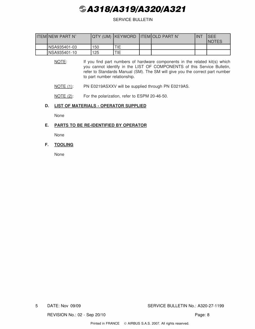
ITEM NEW PART N˚ QTY (UM) KEYWORD ITEM OLD PART N˚ INT SEENOTES
NSA935401-03 150 TIENSA935401-10 125 TIE
NOTE: If you find part numbers of hardware components in the related kit(s) whichyou cannot identify in the LIST OF COMPONENTS of this Service Bulletin,refer to Standards Manual (SM). The SM will give you the correct part numberto part number relationship.
NOTE (1): PN E0219ASXXV will be supplied through PN E0219AS.
NOTE (2): For the polarization, refer to ESPM 20-46-50.
D. LIST OF MATERIALS - OPERATOR SUPPLIED
None
E. PARTS TO BE RE-IDENTIFIED BY OPERATOR
None
F. TOOLING
None
DATE: Nov 09/09 SERVICE BULLETIN No.: A320-27-1199
REVISION No.: 02 - Sep 20/10 Page: 8
5
Printed in FRANCE © AIRBUS S.A.S. 2007. All rights reserved.
@A318/A319/A320/A321SERVICE BULLETIN
3. ACCOMPLISHMENT INSTRUCTIONS
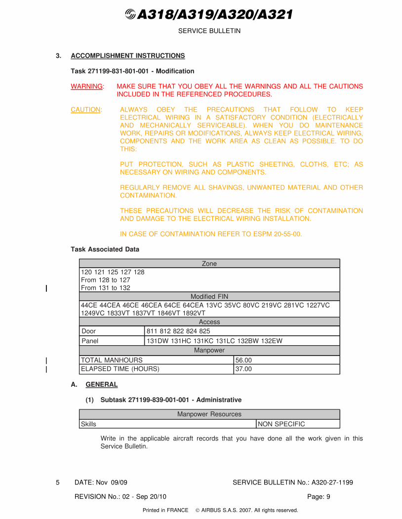
Task 271199-831-801-001 - Modification
WARNING: MAKE SURE THAT YOU OBEY ALL THE WARNINGS AND ALL THE CAUTIONSINCLUDED IN THE REFERENCED PROCEDURES.
CAUTION: ALWAYS OBEY THE PRECAUTIONS THAT FOLLOW TO KEEPELECTRICAL WIRING IN A SATISFACTORY CONDITION (ELECTRICALLYAND MECHANICALLY SERVICEABLE). WHEN YOU DO MAINTENANCEWORK, REPAIRS OR MODIFICATIONS, ALWAYS KEEP ELECTRICAL WIRING,COMPONENTS AND THE WORK AREA AS CLEAN AS POSSIBLE. TO DOTHIS:
PUT PROTECTION, SUCH AS PLASTIC SHEETING, CLOTHS, ETC; ASNECESSARY ON WIRING AND COMPONENTS.
REGULARLY REMOVE ALL SHAVINGS, UNWANTED MATERIAL AND OTHERCONTAMINATION.
THESE PRECAUTIONS WILL DECREASE THE RISK OF CONTAMINATIONAND DAMAGE TO THE ELECTRICAL WIRING INSTALLATION.
IN CASE OF CONTAMINATION REFER TO ESPM 20-55-00.
Task Associated Data
Zone120 121 125 127 128From 128 to 127From 131 to 132
Modified FIN44CE 44CEA 46CE 46CEA 64CE 64CEA 13VC 35VC 80VC 219VC 281VC 1227VC1249VC 1833VT 1837VT 1846VT 1892VT
AccessDoor 811 812 822 824 825
Panel 131DW 131HC 131KC 131LC 132BW 132EWManpower
TOTAL MANHOURS 56.00ELAPSED TIME (HOURS) 37.00
A. GENERAL
(1) Subtask 271199-839-001-001 - Administrative
Manpower Resources
Skills NON SPECIFIC
Write in the applicable aircraft records that you have done all the work given in thisService Bulletin.
DATE: Nov 09/09 SERVICE BULLETIN No.: A320-27-1199
REVISION No.: 02 - Sep 20/10 Page: 9
5
Printed in FRANCE © AIRBUS S.A.S. 2007. All rights reserved.
@A318/A319/A320/A321SERVICE BULLETIN
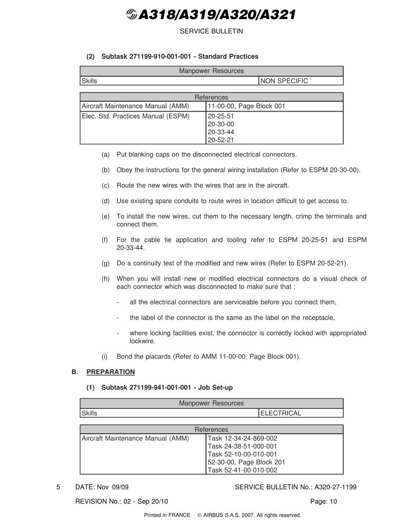
(2) Subtask 271199-910-001-001 - Standard Practices
Manpower Resources
Skills NON SPECIFIC
ReferencesAircraft Maintenance Manual (AMM) 11-00-00, Page Block 001
Elec. Std. Practices Manual (ESPM) 20-25-5120-30-0020-33-4420-52-21
(a) Put blanking caps on the disconnected electrical connectors.
(b) Obey the instructions for the general wiring installation (Refer to ESPM 20-30-00).
(c) Route the new wires with the wires that are in the aircraft.
(d) Use existing spare conduits to route wires in location difficult to get access to.
(e) To install the new wires, cut them to the necessary length, crimp the terminals andconnect them.
(f) For the cable tie application and tooling refer to ESPM 20-25-51 and ESPM20-33-44.
(g) Do a continuity test of the modified and new wires (Refer to ESPM 20-52-21).
(h) When you will install new or modified electrical connectors do a visual check ofeach connector which was disconnected to make sure that :
- all the electrical connectors are serviceable before you connect them,
- the label of the connector is the same as the label on the receptacle,
- where locking facilities exist, the connector is correctly locked with appropriatedlockwire.
(i) Bond the placards (Refer to AMM 11-00-00, Page Block 001).
B. PREPARATION
(1) Subtask 271199-941-001-001 - Job Set-up
Manpower Resources
Skills ELECTRICAL
ReferencesAircraft Maintenance Manual (AMM) Task 12-34-24-869-002
Task 24-38-51-000-001Task 52-10-00-010-00152-30-00, Page Block 201Task 52-41-00-010-002
DATE: Nov 09/09 SERVICE BULLETIN No.: A320-27-1199
REVISION No.: 02 - Sep 20/10 Page: 10
5
Printed in FRANCE © AIRBUS S.A.S. 2007. All rights reserved.
@A318/A319/A320/A321SERVICE BULLETIN
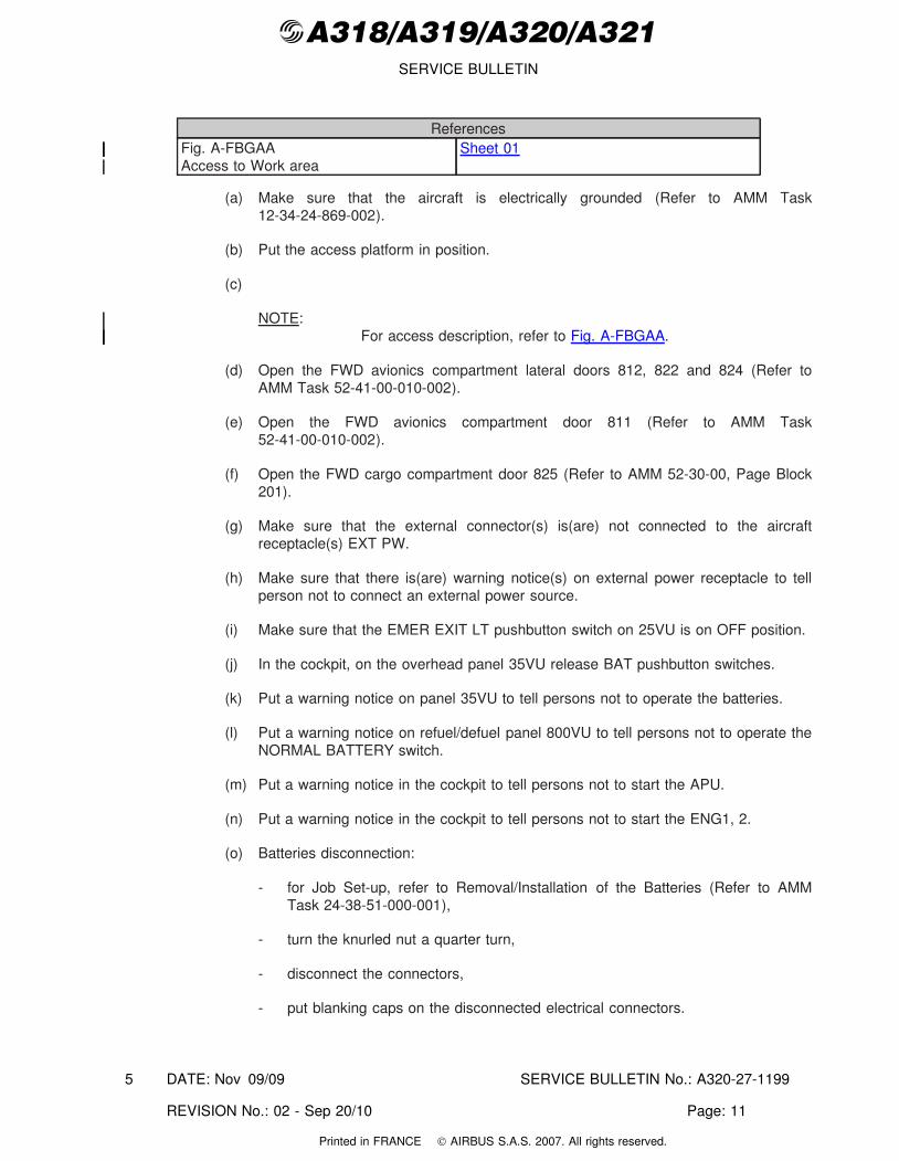
ReferencesFig. A-FBGAAAccess to Work area
Sheet 01
(a) Make sure that the aircraft is electrically grounded (Refer to AMM Task12-34-24-869-002).
(b) Put the access platform in position.
(c)
NOTE:For access description, refer to Fig. A-FBGAA.
(d) Open the FWD avionics compartment lateral doors 812, 822 and 824 (Refer toAMM Task 52-41-00-010-002).
(e) Open the FWD avionics compartment door 811 (Refer to AMM Task52-41-00-010-002).
(f) Open the FWD cargo compartment door 825 (Refer to AMM 52-30-00, Page Block201).
(g) Make sure that the external connector(s) is(are) not connected to the aircraftreceptacle(s) EXT PW.
(h) Make sure that there is(are) warning notice(s) on external power receptacle to tellperson not to connect an external power source.
(i) Make sure that the EMER EXIT LT pushbutton switch on 25VU is on OFF position.
(j) In the cockpit, on the overhead panel 35VU release BAT pushbutton switches.
(k) Put a warning notice on panel 35VU to tell persons not to operate the batteries.
(l) Put a warning notice on refuel/defuel panel 800VU to tell persons not to operate theNORMAL BATTERY switch.
(m) Put a warning notice in the cockpit to tell persons not to start the APU.
(n) Put a warning notice in the cockpit to tell persons not to start the ENG1, 2.
(o) Batteries disconnection:
- for Job Set-up, refer to Removal/Installation of the Batteries (Refer to AMMTask 24-38-51-000-001),
- turn the knurled nut a quarter turn,
- disconnect the connectors,
- put blanking caps on the disconnected electrical connectors.
DATE: Nov 09/09 SERVICE BULLETIN No.: A320-27-1199
REVISION No.: 02 - Sep 20/10 Page: 11
5
Printed in FRANCE © AIRBUS S.A.S. 2007. All rights reserved.
@A318/A319/A320/A321SERVICE BULLETIN
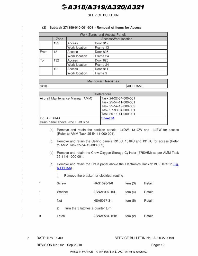
(2) Subtask 271199-010-001-001 - Removal of items for Access
Work Zones and Access PanelsZone Access/Work location
125 Access Door 812Work location Frame 13
From 131 Access Door 825Work location Frame 24
To 132 Access Door 825Work location Frame 24
121 Access Door 811Work location Frame 9
Manpower Resources
Skills AIRFRAME
ReferencesAircraft Maintenance Manual (AMM) Task 24-22-34-000-001
Task 25-54-11-000-001Task 25-54-12-000-002Task 27-93-34-000-001Task 35-11-41-000-001
Fig. A-FBHAADrain panel above 90VU Left side
Sheet 01
(a) Remove and retain the partition panels 131DW, 131CW and 132EW for access(Refer to AMM Task 25-54-11-000-001).
(b) Remove and retain the Ceiling panels 131LC, 131KC and 131HC for access (Referto AMM Task 25-54-12-000-002).
(c) Remove and retain the Crew Oxygen-Storage Cylinder (5750HM) as per AMM Task35-11-41-000-001.
(d) Remove and retain the Drain panel above the Electronics Rack 91VU (Refer to Fig.A-FBHAA).
1 Remove the bracket for electrical routing
1 Screw NAS1096-3-8 Item (3) Retain
1 Washer ASNA2397-10L Item (4) Retain
1 Nut NSA5067-3-1 Item (5) Retain
2 Turn the 3 latches a quarter turn
3 Latch ASNA2584-1201 Item (2) Retain
DATE: Nov 09/09 SERVICE BULLETIN No.: A320-27-1199
REVISION No.: 02 - Sep 20/10 Page: 12
5
Printed in FRANCE © AIRBUS S.A.S. 2007. All rights reserved.
@A318/A319/A320/A321SERVICE BULLETIN
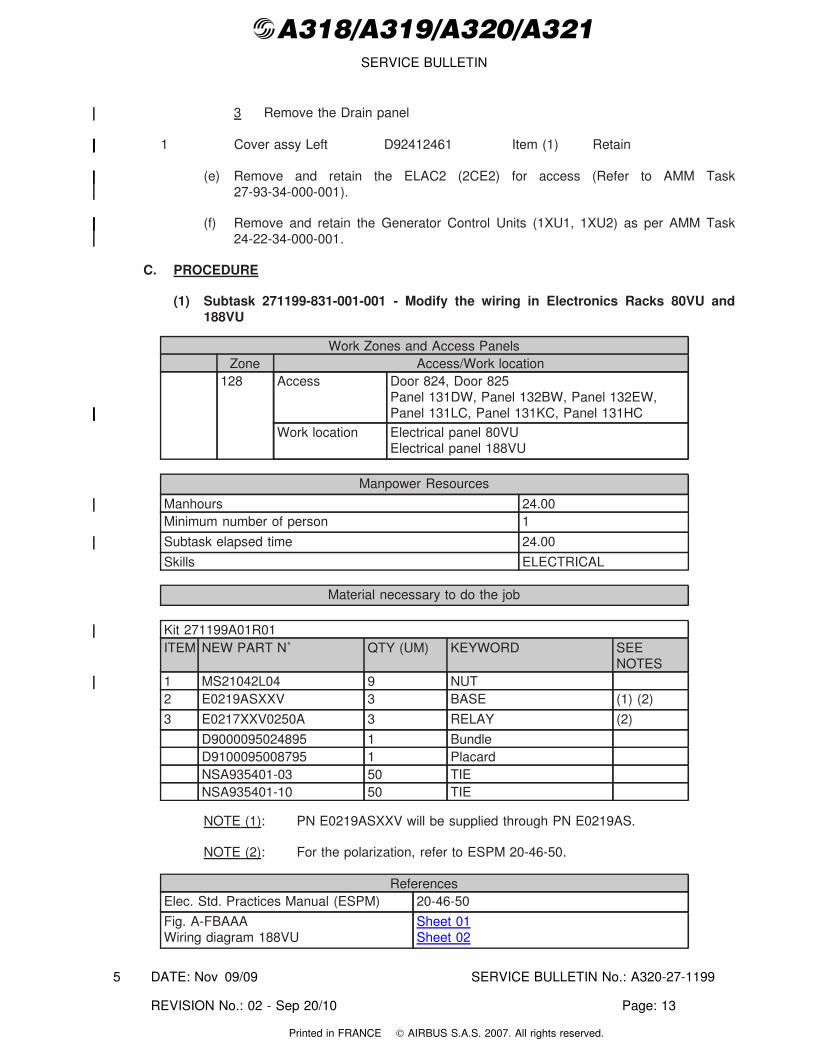
3 Remove the Drain panel
1 Cover assy Left D92412461 Item (1) Retain
(e) Remove and retain the ELAC2 (2CE2) for access (Refer to AMM Task27-93-34-000-001).
(f) Remove and retain the Generator Control Units (1XU1, 1XU2) as per AMM Task24-22-34-000-001.
C. PROCEDURE
(1) Subtask 271199-831-001-001 - Modify the wiring in Electronics Racks 80VU and188VU
Work Zones and Access PanelsZone Access/Work location
128 Access Door 824, Door 825Panel 131DW, Panel 132BW, Panel 132EW,Panel 131LC, Panel 131KC, Panel 131HC
Work location Electrical panel 80VUElectrical panel 188VU
Manpower Resources
Manhours 24.00Minimum number of person 1
Subtask elapsed time 24.00
Skills ELECTRICAL
Material necessary to do the job
Kit 271199A01R01ITEM NEW PART N˚ QTY (UM) KEYWORD SEE
NOTES1 MS21042L04 9 NUT2 E0219ASXXV 3 BASE (1) (2)
3 E0217XXV0250A 3 RELAY (2)
D9000095024895 1 BundleD9100095008795 1 PlacardNSA935401-03 50 TIENSA935401-10 50 TIE
NOTE (1): PN E0219ASXXV will be supplied through PN E0219AS.
NOTE (2): For the polarization, refer to ESPM 20-46-50.
ReferencesElec. Std. Practices Manual (ESPM) 20-46-50
Fig. A-FBAAAWiring diagram 188VU
Sheet 01Sheet 02
DATE: Nov 09/09 SERVICE BULLETIN No.: A320-27-1199
REVISION No.: 02 - Sep 20/10 Page: 13
5
Printed in FRANCE © AIRBUS S.A.S. 2007. All rights reserved.
@A318/A319/A320/A321SERVICE BULLETIN
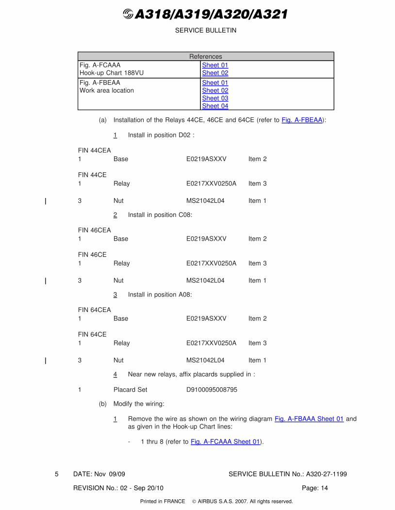
ReferencesFig. A-FCAAAHook-up Chart 188VU
Sheet 01Sheet 02
Fig. A-FBEAAWork area location
Sheet 01Sheet 02Sheet 03Sheet 04
(a) Installation of the Relays 44CE, 46CE and 64CE (refer to Fig. A-FBEAA):
1 Install in position D02 :
FIN 44CEA1 Base E0219ASXXV Item 2
FIN 44CE1 Relay E0217XXV0250A Item 3
3 Nut MS21042L04 Item 1
2 Install in position C08:
FIN 46CEA1 Base E0219ASXXV Item 2
FIN 46CE1 Relay E0217XXV0250A Item 3
3 Nut MS21042L04 Item 1
3 Install in position A08:
FIN 64CEA1 Base E0219ASXXV Item 2
FIN 64CE1 Relay E0217XXV0250A Item 3
3 Nut MS21042L04 Item 1
4 Near new relays, affix placards supplied in :
1 Placard Set D9100095008795
(b) Modify the wiring:
1 Remove the wire as shown on the wiring diagram Fig. A-FBAAA Sheet 01 andas given in the Hook-up Chart lines:
- 1 thru 8 (refer to Fig. A-FCAAA Sheet 01).
DATE: Nov 09/09 SERVICE BULLETIN No.: A320-27-1199
REVISION No.: 02 - Sep 20/10 Page: 14
5
Printed in FRANCE © AIRBUS S.A.S. 2007. All rights reserved.
@A318/A319/A320/A321SERVICE BULLETIN
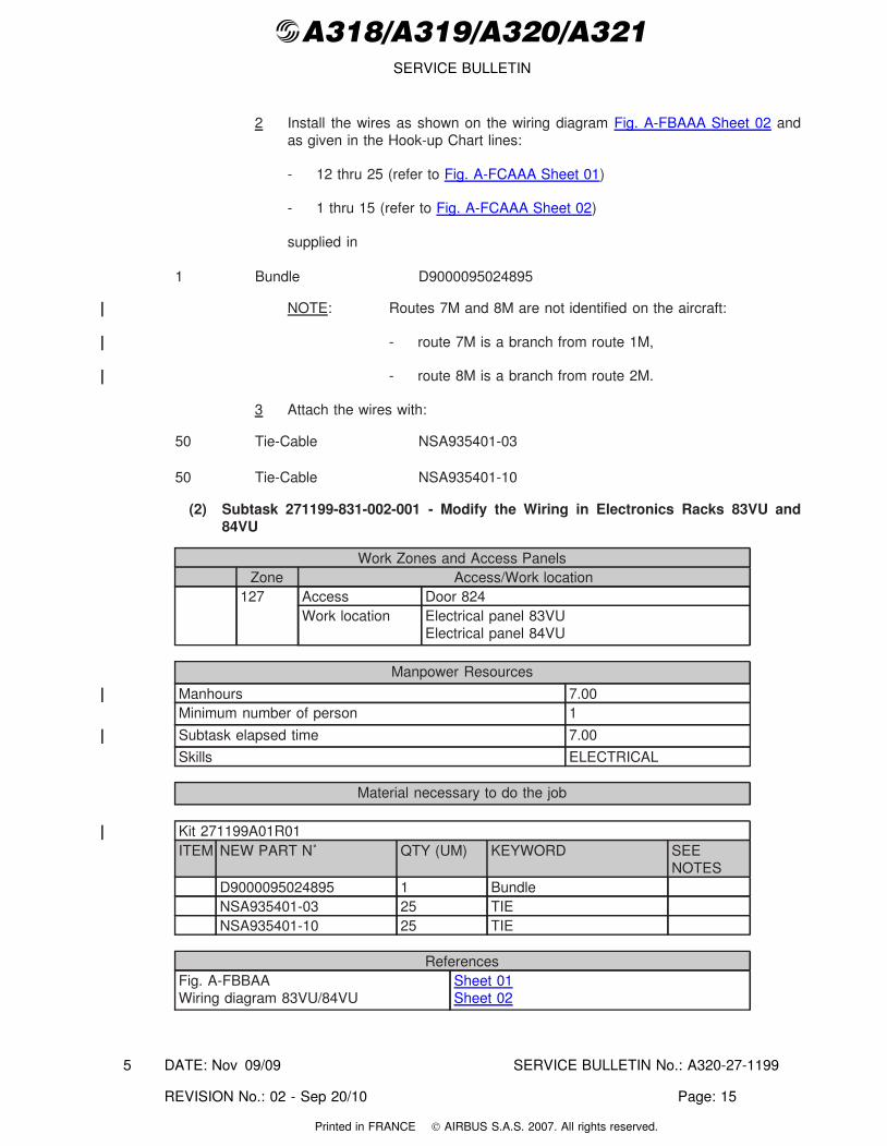
2 Install the wires as shown on the wiring diagram Fig. A-FBAAA Sheet 02 andas given in the Hook-up Chart lines:
- 12 thru 25 (refer to Fig. A-FCAAA Sheet 01)
- 1 thru 15 (refer to Fig. A-FCAAA Sheet 02)
supplied in
1 Bundle D9000095024895
NOTE: Routes 7M and 8M are not identified on the aircraft:
- route 7M is a branch from route 1M,
- route 8M is a branch from route 2M.
3 Attach the wires with:
50 Tie-Cable NSA935401-03
50 Tie-Cable NSA935401-10
(2) Subtask 271199-831-002-001 - Modify the Wiring in Electronics Racks 83VU and84VU
Work Zones and Access PanelsZone Access/Work location
127 Access Door 824Work location Electrical panel 83VU
Electrical panel 84VU
Manpower Resources
Manhours 7.00Minimum number of person 1
Subtask elapsed time 7.00
Skills ELECTRICAL
Material necessary to do the job
Kit 271199A01R01ITEM NEW PART N˚ QTY (UM) KEYWORD SEE
NOTESD9000095024895 1 BundleNSA935401-03 25 TIENSA935401-10 25 TIE
ReferencesFig. A-FBBAAWiring diagram 83VU/84VU
Sheet 01Sheet 02
DATE: Nov 09/09 SERVICE BULLETIN No.: A320-27-1199
REVISION No.: 02 - Sep 20/10 Page: 15
5
Printed in FRANCE © AIRBUS S.A.S. 2007. All rights reserved.
@A318/A319/A320/A321SERVICE BULLETIN
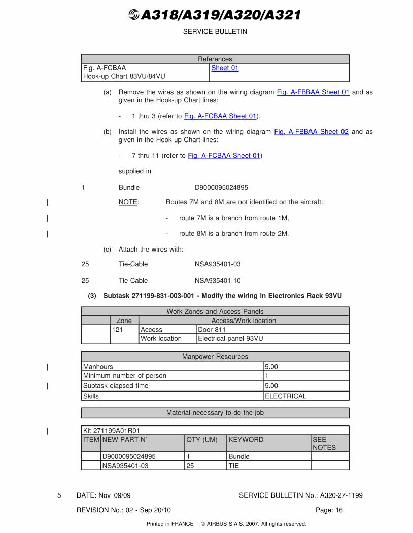
ReferencesFig. A-FCBAAHook-up Chart 83VU/84VU
Sheet 01
(a) Remove the wires as shown on the wiring diagram Fig. A-FBBAA Sheet 01 and asgiven in the Hook-up Chart lines:
- 1 thru 3 (refer to Fig. A-FCBAA Sheet 01).
(b) Install the wires as shown on the wiring diagram Fig. A-FBBAA Sheet 02 and asgiven in the Hook-up Chart lines:
- 7 thru 11 (refer to Fig. A-FCBAA Sheet 01)
supplied in
1 Bundle D9000095024895
NOTE: Routes 7M and 8M are not identified on the aircraft:
- route 7M is a branch from route 1M,
- route 8M is a branch from route 2M.
(c) Attach the wires with:
25 Tie-Cable NSA935401-03
25 Tie-Cable NSA935401-10
(3) Subtask 271199-831-003-001 - Modify the wiring in Electronics Rack 93VU
Work Zones and Access PanelsZone Access/Work location
121 Access Door 811Work location Electrical panel 93VU
Manpower Resources
Manhours 5.00Minimum number of person 1
Subtask elapsed time 5.00
Skills ELECTRICAL
Material necessary to do the job
Kit 271199A01R01ITEM NEW PART N˚ QTY (UM) KEYWORD SEE
NOTESD9000095024895 1 BundleNSA935401-03 25 TIE
DATE: Nov 09/09 SERVICE BULLETIN No.: A320-27-1199
REVISION No.: 02 - Sep 20/10 Page: 16
5
Printed in FRANCE © AIRBUS S.A.S. 2007. All rights reserved.
@A318/A319/A320/A321SERVICE BULLETIN
ReferencesAircraft Maintenance Manual (AMM) Task 20-28-00-912-004
Task 21-63-34-000-001Task 21-63-34-400-001Task 27-94-34-000-001Task 27-94-34-400-001Task 32-31-71-000-001Task 32-31-71-400-001
Fig. A-FBCAAWiring diagram 93VU
Sheet 01
Fig. A-FCCAAHook-up Chart 93VU
Sheet 01
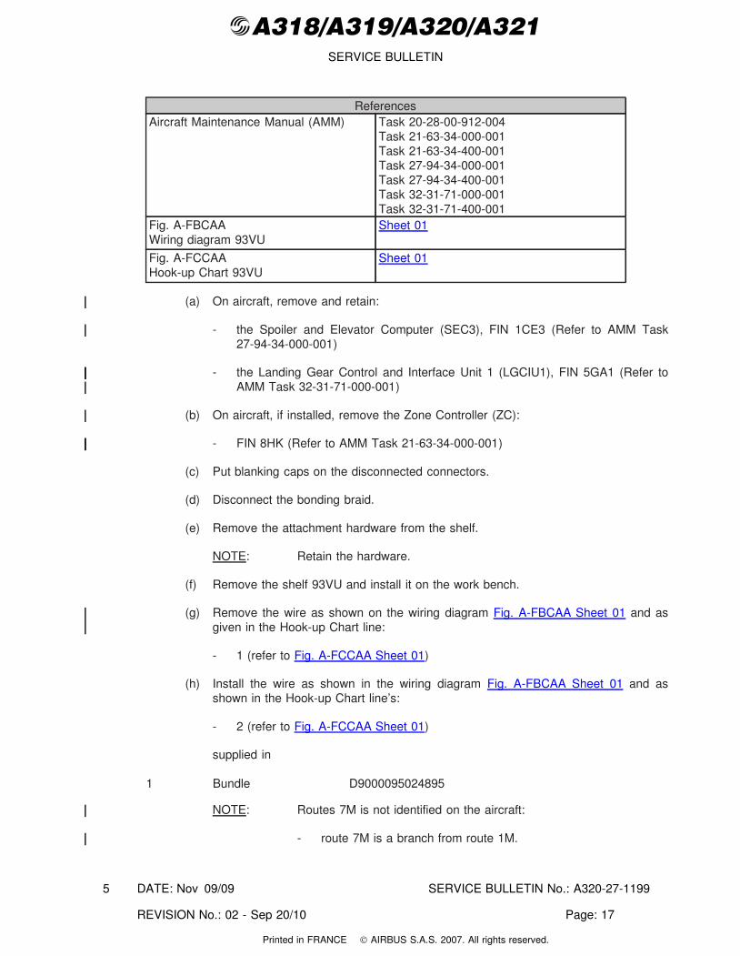
(a) On aircraft, remove and retain:
- the Spoiler and Elevator Computer (SEC3), FIN 1CE3 (Refer to AMM Task27-94-34-000-001)
- the Landing Gear Control and Interface Unit 1 (LGCIU1), FIN 5GA1 (Refer toAMM Task 32-31-71-000-001)
(b) On aircraft, if installed, remove the Zone Controller (ZC):
- FIN 8HK (Refer to AMM Task 21-63-34-000-001)
(c) Put blanking caps on the disconnected connectors.
(d) Disconnect the bonding braid.
(e) Remove the attachment hardware from the shelf.
NOTE: Retain the hardware.
(f) Remove the shelf 93VU and install it on the work bench.
(g) Remove the wire as shown on the wiring diagram Fig. A-FBCAA Sheet 01 and asgiven in the Hook-up Chart line:
- 1 (refer to Fig. A-FCCAA Sheet 01)
(h) Install the wire as shown in the wiring diagram Fig. A-FBCAA Sheet 01 and asshown in the Hook-up Chart line’s:
- 2 (refer to Fig. A-FCCAA Sheet 01)
supplied in
1 Bundle D9000095024895
NOTE: Routes 7M is not identified on the aircraft:
- route 7M is a branch from route 1M.
DATE: Nov 09/09 SERVICE BULLETIN No.: A320-27-1199
REVISION No.: 02 - Sep 20/10 Page: 17
5
Printed in FRANCE © AIRBUS S.A.S. 2007. All rights reserved.
@A318/A319/A320/A321SERVICE BULLETIN
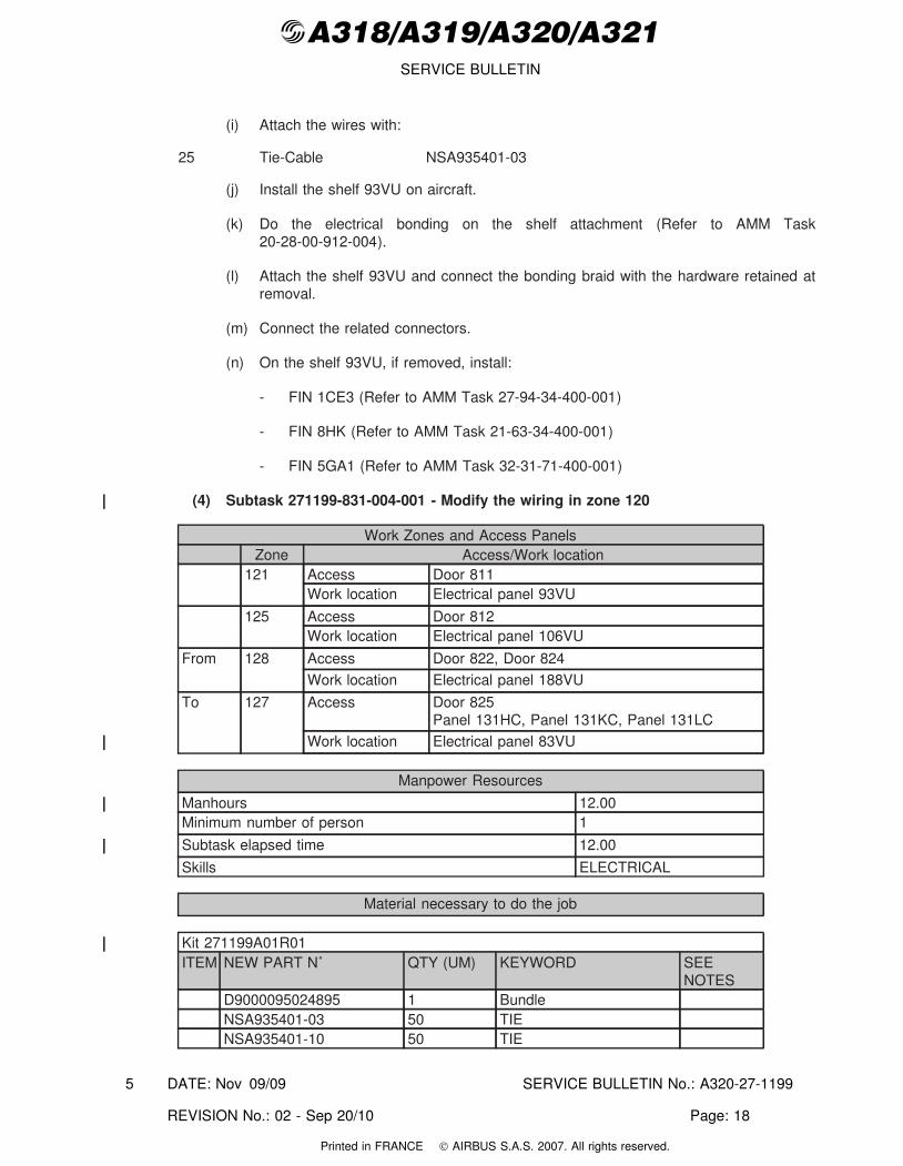
(i) Attach the wires with:
25 Tie-Cable NSA935401-03
(j) Install the shelf 93VU on aircraft.
(k) Do the electrical bonding on the shelf attachment (Refer to AMM Task20-28-00-912-004).
(l) Attach the shelf 93VU and connect the bonding braid with the hardware retained atremoval.
(m) Connect the related connectors.
(n) On the shelf 93VU, if removed, install:
- FIN 1CE3 (Refer to AMM Task 27-94-34-400-001)
- FIN 8HK (Refer to AMM Task 21-63-34-400-001)
- FIN 5GA1 (Refer to AMM Task 32-31-71-400-001)
(4) Subtask 271199-831-004-001 - Modify the wiring in zone 120
Work Zones and Access PanelsZone Access/Work location
121 Access Door 811Work location Electrical panel 93VU
125 Access Door 812Work location Electrical panel 106VU
From 128 Access Door 822, Door 824Work location Electrical panel 188VU
To 127 Access Door 825Panel 131HC, Panel 131KC, Panel 131LC
Work location Electrical panel 83VU
Manpower Resources
Manhours 12.00Minimum number of person 1
Subtask elapsed time 12.00
Skills ELECTRICAL
Material necessary to do the job
Kit 271199A01R01ITEM NEW PART N˚ QTY (UM) KEYWORD SEE
NOTESD9000095024895 1 BundleNSA935401-03 50 TIENSA935401-10 50 TIE
DATE: Nov 09/09 SERVICE BULLETIN No.: A320-27-1199
REVISION No.: 02 - Sep 20/10 Page: 18
5
Printed in FRANCE © AIRBUS S.A.S. 2007. All rights reserved.
@A318/A319/A320/A321SERVICE BULLETIN
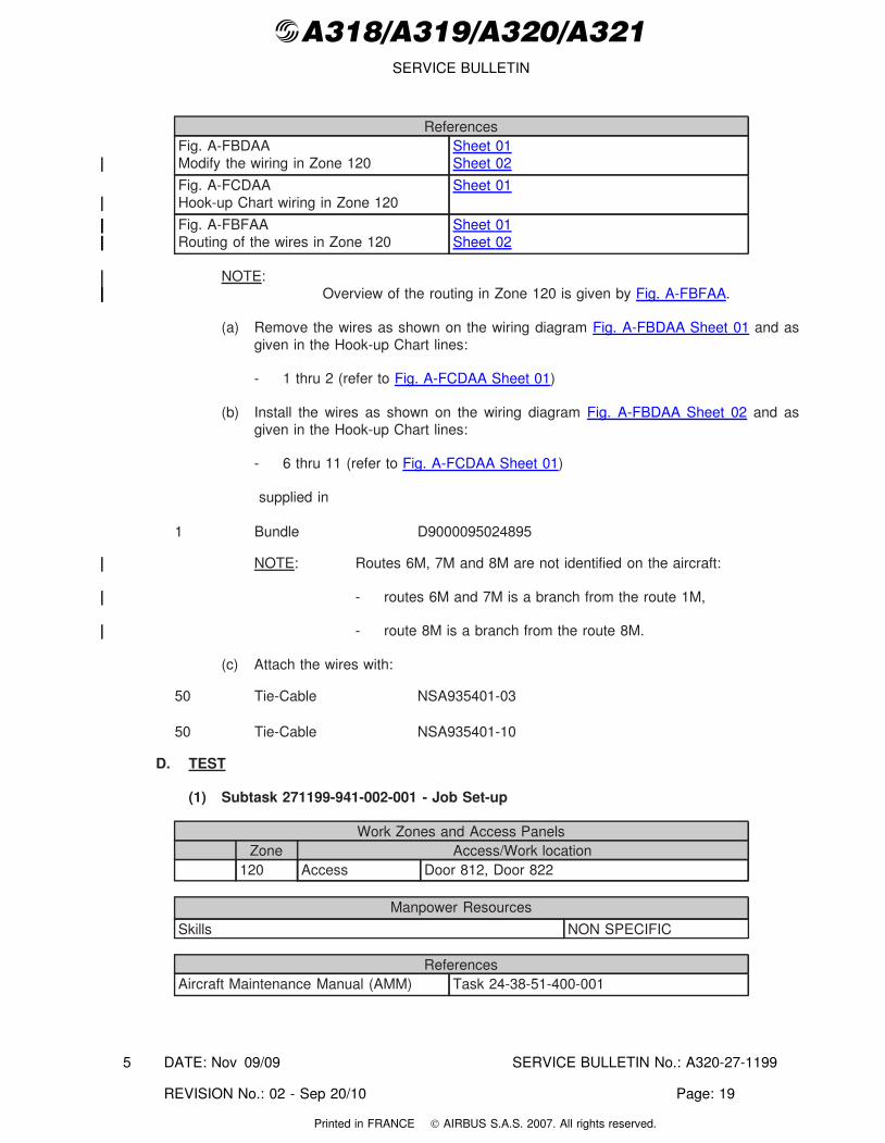
ReferencesFig. A-FBDAAModify the wiring in Zone 120
Sheet 01Sheet 02
Fig. A-FCDAAHook-up Chart wiring in Zone 120
Sheet 01
Fig. A-FBFAARouting of the wires in Zone 120
Sheet 01Sheet 02
NOTE:Overview of the routing in Zone 120 is given by Fig. A-FBFAA.
(a) Remove the wires as shown on the wiring diagram Fig. A-FBDAA Sheet 01 and asgiven in the Hook-up Chart lines:
- 1 thru 2 (refer to Fig. A-FCDAA Sheet 01)
(b) Install the wires as shown on the wiring diagram Fig. A-FBDAA Sheet 02 and asgiven in the Hook-up Chart lines:
- 6 thru 11 (refer to Fig. A-FCDAA Sheet 01)
supplied in
1 Bundle D9000095024895
NOTE: Routes 6M, 7M and 8M are not identified on the aircraft:
- routes 6M and 7M is a branch from the route 1M,
- route 8M is a branch from the route 8M.
(c) Attach the wires with:
50 Tie-Cable NSA935401-03
50 Tie-Cable NSA935401-10
D. TEST
(1) Subtask 271199-941-002-001 - Job Set-up
Work Zones and Access PanelsZone Access/Work location
120 Access Door 812, Door 822
Manpower Resources
Skills NON SPECIFIC
ReferencesAircraft Maintenance Manual (AMM) Task 24-38-51-400-001
DATE: Nov 09/09 SERVICE BULLETIN No.: A320-27-1199
REVISION No.: 02 - Sep 20/10 Page: 19
5
Printed in FRANCE © AIRBUS S.A.S. 2007. All rights reserved.
@A318/A319/A320/A321SERVICE BULLETIN
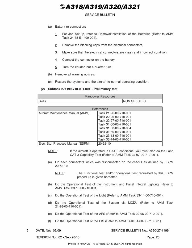
(a) Battery re-connection:
1 For Job Set-up, refer to Removal/Installation of the Batteries (Refer to AMMTask 24-38-51-400-001),
2 Remove the blanking caps from the electrical connectors,
3 Make sure that the electrical connectors are clean and in correct condition,
4 Connect the connector on the battery,
5 Turn the knurled nut a quarter turn.
(b) Remove all warning notices.
(c) Restore the systems and the aircraft to normal operating condition.
(2) Subtask 271199-710-001-001 - Preliminary test
Manpower Resources
Skills NON SPECIFIC
ReferencesAircraft Maintenance Manual (AMM) Task 21-26-00-710-001
Task 22-96-00-710-001Task 22-97-00-710-001Task 31-50-00-710-001Task 31-50-00-710-004Task 31-60-00-710-001Task 33-13-00-710-001Task 33-14-00-710-001
Elec. Std. Practices Manual (ESPM) 20-52-10
NOTE: If the aircraft is operated in CAT 3 conditions, you must also do the LandCAT 3 Capability Test (Refer to AMM Task 22-97-00-710-001).
(a) On each connectors which was disconnected do the checks as defined by ESPM20-52-10.
NOTE: The Functional test and/or operational test requested by this ESPMprocedure is given hereafter.
(b) Do the Operational Test of the Instrument and Panel Integral Lighting (Refer toAMM Task 33-13-00-710-001).
(c) Do the Operational Test of the Light (Refer to AMM Task 33-14-00-710-001).
(d) Do the Operational Test of the System via MCDU (Refer to AMM Task21-26-00-710-001).
(e) Do the Operational Test of the AFS (Refer to AMM Task 22-96-00-710-001).
(f) Do the Operational Test of the EIS (Refer to AMM Task 31-60-00-710-001).
DATE: Nov 09/09 SERVICE BULLETIN No.: A320-27-1199
REVISION No.: 02 - Sep 20/10 Page: 20
5
Printed in FRANCE © AIRBUS S.A.S. 2007. All rights reserved.
@A318/A319/A320/A321SERVICE BULLETIN
(g) Do the Operational Test of the ECAM Control Panel (Refer to AMM Task31-50-00-710-004).
(h) Ground Scanning of the Central Warning System (Refer to AMM Task31-50-00-710-001).
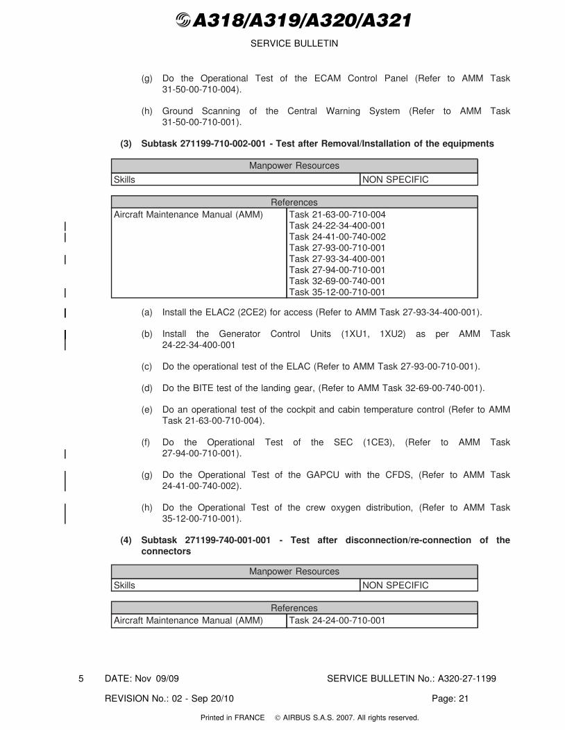
(3) Subtask 271199-710-002-001 - Test after Removal/Installation of the equipments
Manpower Resources
Skills NON SPECIFIC
ReferencesAircraft Maintenance Manual (AMM) Task 21-63-00-710-004
Task 24-22-34-400-001Task 24-41-00-740-002Task 27-93-00-710-001Task 27-93-34-400-001Task 27-94-00-710-001Task 32-69-00-740-001Task 35-12-00-710-001
(a) Install the ELAC2 (2CE2) for access (Refer to AMM Task 27-93-34-400-001).
(b) Install the Generator Control Units (1XU1, 1XU2) as per AMM Task24-22-34-400-001
(c) Do the operational test of the ELAC (Refer to AMM Task 27-93-00-710-001).
(d) Do the BITE test of the landing gear, (Refer to AMM Task 32-69-00-740-001).
(e) Do an operational test of the cockpit and cabin temperature control (Refer to AMMTask 21-63-00-710-004).
(f) Do the Operational Test of the SEC (1CE3), (Refer to AMM Task27-94-00-710-001).
(g) Do the Operational Test of the GAPCU with the CFDS, (Refer to AMM Task24-41-00-740-002).
(h) Do the Operational Test of the crew oxygen distribution, (Refer to AMM Task35-12-00-710-001).
(4) Subtask 271199-740-001-001 - Test after disconnection/re-connection of theconnectors
Manpower Resources
Skills NON SPECIFIC
ReferencesAircraft Maintenance Manual (AMM) Task 24-24-00-710-001
DATE: Nov 09/09 SERVICE BULLETIN No.: A320-27-1199
REVISION No.: 02 - Sep 20/10 Page: 21
5
Printed in FRANCE © AIRBUS S.A.S. 2007. All rights reserved.
@A318/A319/A320/A321SERVICE BULLETIN
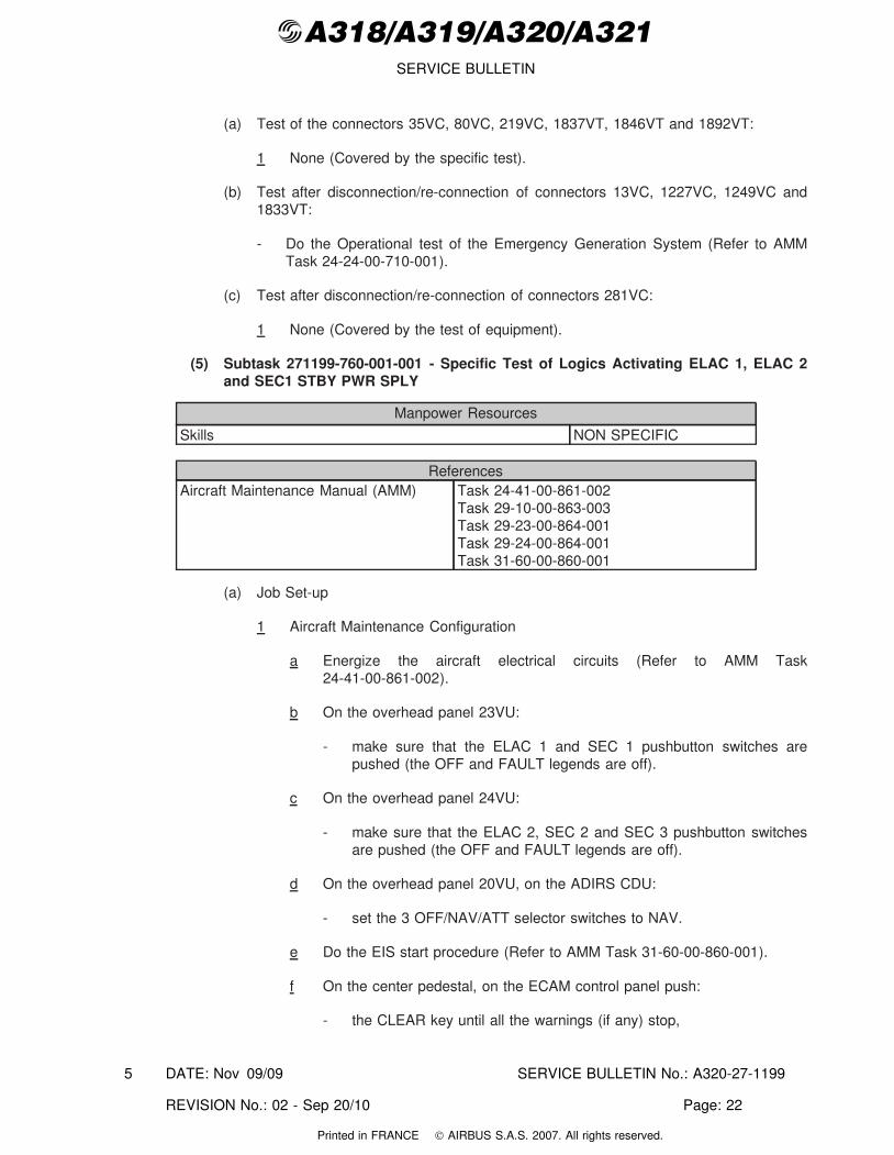
(a) Test of the connectors 35VC, 80VC, 219VC, 1837VT, 1846VT and 1892VT:
1 None (Covered by the specific test).
(b) Test after disconnection/re-connection of connectors 13VC, 1227VC, 1249VC and1833VT:
- Do the Operational test of the Emergency Generation System (Refer to AMMTask 24-24-00-710-001).
(c) Test after disconnection/re-connection of connectors 281VC:
1 None (Covered by the test of equipment).
(5) Subtask 271199-760-001-001 - Specific Test of Logics Activating ELAC 1, ELAC 2and SEC1 STBY PWR SPLY
Manpower Resources
Skills NON SPECIFIC
ReferencesAircraft Maintenance Manual (AMM) Task 24-41-00-861-002
Task 29-10-00-863-003Task 29-23-00-864-001Task 29-24-00-864-001Task 31-60-00-860-001
(a) Job Set-up
1 Aircraft Maintenance Configuration
a Energize the aircraft electrical circuits (Refer to AMM Task24-41-00-861-002).
b On the overhead panel 23VU:
- make sure that the ELAC 1 and SEC 1 pushbutton switches arepushed (the OFF and FAULT legends are off).
c On the overhead panel 24VU:
- make sure that the ELAC 2, SEC 2 and SEC 3 pushbutton switchesare pushed (the OFF and FAULT legends are off).
d On the overhead panel 20VU, on the ADIRS CDU:
- set the 3 OFF/NAV/ATT selector switches to NAV.
e Do the EIS start procedure (Refer to AMM Task 31-60-00-860-001).
f On the center pedestal, on the ECAM control panel push:
- the CLEAR key until all the warnings (if any) stop,
DATE: Nov 09/09 SERVICE BULLETIN No.: A320-27-1199
REVISION No.: 02 - Sep 20/10 Page: 22
5
Printed in FRANCE © AIRBUS S.A.S. 2007. All rights reserved.
@A318/A319/A320/A321SERVICE BULLETIN
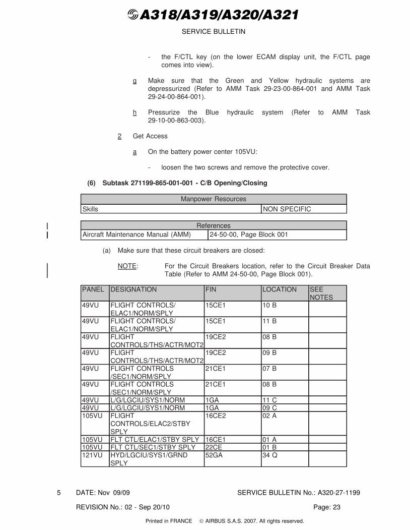
- the F/CTL key (on the lower ECAM display unit, the F/CTL pagecomes into view).
g Make sure that the Green and Yellow hydraulic systems aredepressurized (Refer to AMM Task 29-23-00-864-001 and AMM Task29-24-00-864-001).
h Pressurize the Blue hydraulic system (Refer to AMM Task29-10-00-863-003).
2 Get Access
a On the battery power center 105VU:
- loosen the two screws and remove the protective cover.
(6) Subtask 271199-865-001-001 - C/B Opening/Closing
Manpower Resources
Skills NON SPECIFIC
ReferencesAircraft Maintenance Manual (AMM) 24-50-00, Page Block 001
(a) Make sure that these circuit breakers are closed:
NOTE: For the Circuit Breakers location, refer to the Circuit Breaker DataTable (Refer to AMM 24-50-00, Page Block 001).
PANEL DESIGNATION FIN LOCATION SEENOTES
49VU FLIGHT CONTROLS/ELAC1/NORM/SPLY
15CE1 10 B
49VU FLIGHT CONTROLS/ELAC1/NORM/SPLY
15CE1 11 B
49VU FLIGHTCONTROLS/THS/ACTR/MOT2
19CE2 08 B
49VU FLIGHTCONTROLS/THS/ACTR/MOT2
19CE2 09 B
49VU FLIGHT CONTROLS/SEC1/NORM/SPLY
21CE1 07 B
49VU FLIGHT CONTROLS/SEC1/NORM/SPLY
21CE1 08 B
49VU L/G/LGCIU/SYS1/NORM 1GA 11 C49VU L/G/LGCIU/SYS1/NORM 1GA 09 C105VU FLIGHT
CONTROLS/ELAC2/STBYSPLY
16CE2 02 A
105VU FLT CTL/ELAC1/STBY SPLY 16CE1 01 A105VU FLT CTL/SEC1/STBY SPLY 22CE 01 B121VU HYD/LGCIU/SYS1/GRND
SPLY52GA 34 Q
DATE: Nov 09/09 SERVICE BULLETIN No.: A320-27-1199
REVISION No.: 02 - Sep 20/10 Page: 23
5
Printed in FRANCE © AIRBUS S.A.S. 2007. All rights reserved.
@A318/A319/A320/A321SERVICE BULLETIN
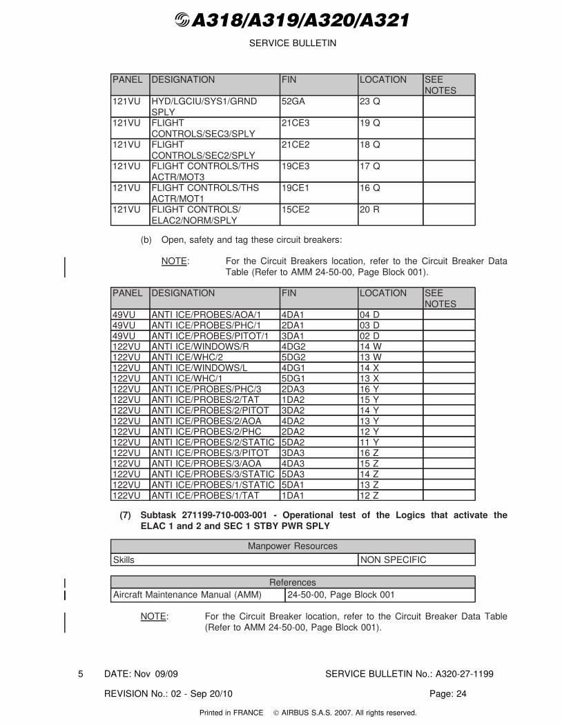
PANEL DESIGNATION FIN LOCATION SEENOTES
121VU HYD/LGCIU/SYS1/GRNDSPLY
52GA 23 Q
121VU FLIGHTCONTROLS/SEC3/SPLY
21CE3 19 Q
121VU FLIGHTCONTROLS/SEC2/SPLY
21CE2 18 Q
121VU FLIGHT CONTROLS/THSACTR/MOT3
19CE3 17 Q
121VU FLIGHT CONTROLS/THSACTR/MOT1
19CE1 16 Q
121VU FLIGHT CONTROLS/ELAC2/NORM/SPLY
15CE2 20 R
(b) Open, safety and tag these circuit breakers:
NOTE: For the Circuit Breakers location, refer to the Circuit Breaker DataTable (Refer to AMM 24-50-00, Page Block 001).
PANEL DESIGNATION FIN LOCATION SEENOTES
49VU ANTI ICE/PROBES/AOA/1 4DA1 04 D49VU ANTI ICE/PROBES/PHC/1 2DA1 03 D49VU ANTI ICE/PROBES/PITOT/1 3DA1 02 D122VU ANTI ICE/WINDOWS/R 4DG2 14 W122VU ANTI ICE/WHC/2 5DG2 13 W122VU ANTI ICE/WINDOWS/L 4DG1 14 X122VU ANTI ICE/WHC/1 5DG1 13 X122VU ANTI ICE/PROBES/PHC/3 2DA3 16 Y122VU ANTI ICE/PROBES/2/TAT 1DA2 15 Y122VU ANTI ICE/PROBES/2/PITOT 3DA2 14 Y122VU ANTI ICE/PROBES/2/AOA 4DA2 13 Y122VU ANTI ICE/PROBES/2/PHC 2DA2 12 Y122VU ANTI ICE/PROBES/2/STATIC 5DA2 11 Y122VU ANTI ICE/PROBES/3/PITOT 3DA3 16 Z122VU ANTI ICE/PROBES/3/AOA 4DA3 15 Z122VU ANTI ICE/PROBES/3/STATIC 5DA3 14 Z122VU ANTI ICE/PROBES/1/STATIC 5DA1 13 Z122VU ANTI ICE/PROBES/1/TAT 1DA1 12 Z
(7) Subtask 271199-710-003-001 - Operational test of the Logics that activate theELAC 1 and 2 and SEC 1 STBY PWR SPLY
Manpower Resources
Skills NON SPECIFIC
ReferencesAircraft Maintenance Manual (AMM) 24-50-00, Page Block 001
NOTE: For the Circuit Breaker location, refer to the Circuit Breaker Data Table(Refer to AMM 24-50-00, Page Block 001).
DATE: Nov 09/09 SERVICE BULLETIN No.: A320-27-1199
REVISION No.: 02 - Sep 20/10 Page: 24
5
Printed in FRANCE © AIRBUS S.A.S. 2007. All rights reserved.
@A318/A319/A320/A321SERVICE BULLETIN
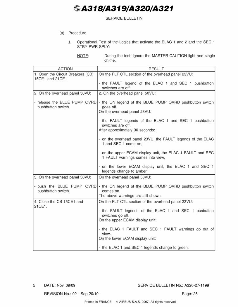
(a) Procedure
1 Operational Test of the Logics that activate the ELAC 1 and 2 and the SEC 1STBY PWR SPLY:
NOTE: During the test, ignore the MASTER CAUTION light and singlechime.
ACTION RESULT1. Open the Circuit Breakers (CB)15CE1 and 21CE1.
On the FLT CTL section of the overhead panel 23VU:
- the FAULT legend of the ELAC 1 and SEC 1 pushbuttonswitches are off.
2. On the overhead panel 50VU:
- release the BLUE PUMP OVRDpushbutton switch.
2. On the overhead panel 50VU:
- the ON legend of the BLUE PUMP OVRD pushbutton switchgoes off.
On the overhead panel 23VU:
- the FAULT legends of the ELAC 1 and SEC 1 pushbuttonswitches are off.
After approximately 30 seconds:
- on the overhead panel 23VU, the FAULT legends of the ELAC1 and SEC 1 come on,
- on the upper ECAM display unit, the ELAC 1 FAULT and SEC1 FAULT warnings comes into view,
- on the lower ECAM display unit, the ELAC 1 and SEC 1legends change to amber.
3. On the overhead panel 50VU:
- push the BLUE PUMP OVRDpushbutton switch.
On the overhead panel 50VU:
- the ON legend of the BLUE PUMP OVRD pushbutton switchcomes on.
The above warnings are still shown.
4. Close the CB 15CE1 and21CE1.
On the FLT CTL section of the overhead panel 23VU:
- the FAULT legends of the ELAC 1 and SEC 1 pusbuttonswitches go off.
On the upper ECAM display unit:
- the ELAC 1 FAULT and SEC 1 FAULT warnings go out ofview.
On the lower ECAM display unit:
- the ELAC 1 and SEC 1 legends change to green.
DATE: Nov 09/09 SERVICE BULLETIN No.: A320-27-1199
REVISION No.: 02 - Sep 20/10 Page: 25
5
Printed in FRANCE © AIRBUS S.A.S. 2007. All rights reserved.
@A318/A319/A320/A321SERVICE BULLETIN
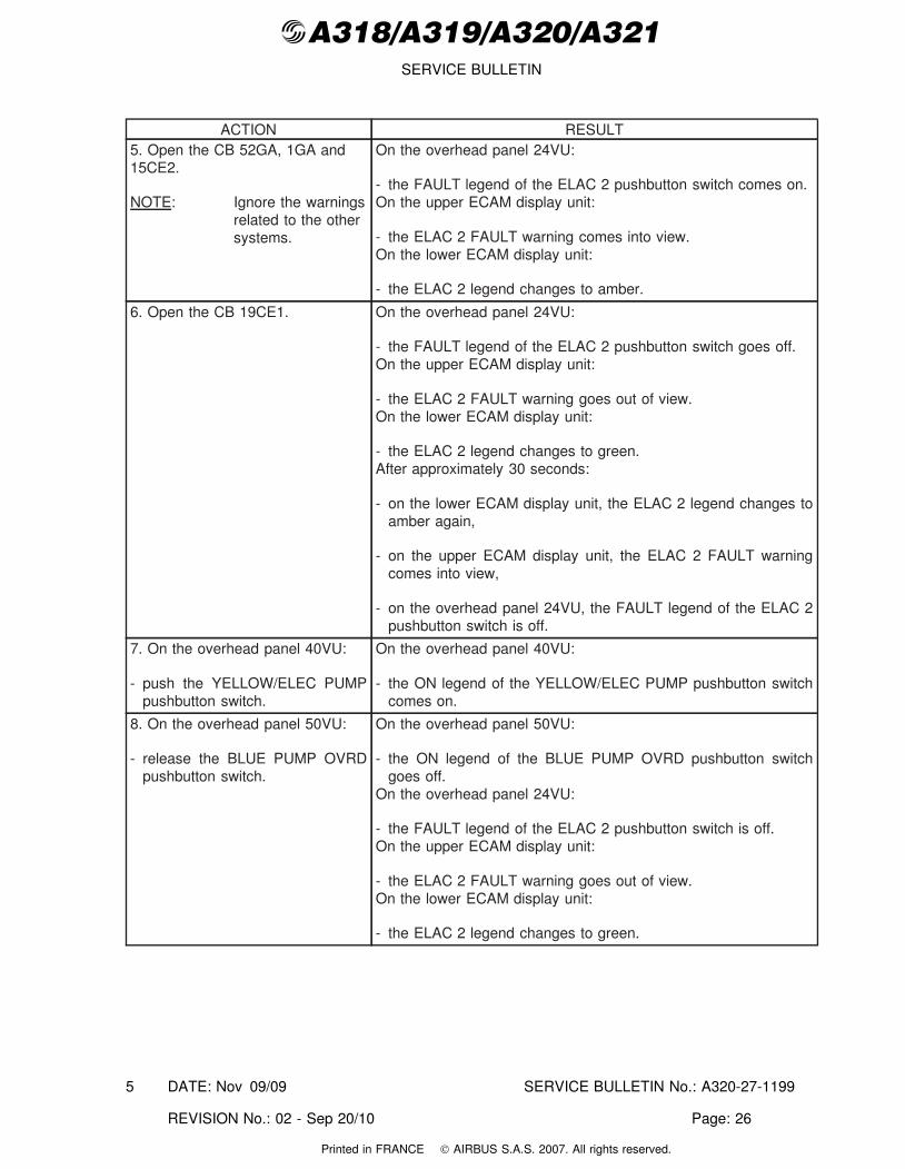
ACTION RESULT5. Open the CB 52GA, 1GA and15CE2.
NOTE: Ignore the warningsrelated to the othersystems.
On the overhead panel 24VU:
- the FAULT legend of the ELAC 2 pushbutton switch comes on.On the upper ECAM display unit:
- the ELAC 2 FAULT warning comes into view.On the lower ECAM display unit:
- the ELAC 2 legend changes to amber.
6. Open the CB 19CE1. On the overhead panel 24VU:
- the FAULT legend of the ELAC 2 pushbutton switch goes off.On the upper ECAM display unit:
- the ELAC 2 FAULT warning goes out of view.On the lower ECAM display unit:
- the ELAC 2 legend changes to green.After approximately 30 seconds:
- on the lower ECAM display unit, the ELAC 2 legend changes toamber again,
- on the upper ECAM display unit, the ELAC 2 FAULT warningcomes into view,
- on the overhead panel 24VU, the FAULT legend of the ELAC 2pushbutton switch is off.
7. On the overhead panel 40VU:
- push the YELLOW/ELEC PUMPpushbutton switch.
On the overhead panel 40VU:
- the ON legend of the YELLOW/ELEC PUMP pushbutton switchcomes on.
8. On the overhead panel 50VU:
- release the BLUE PUMP OVRDpushbutton switch.
On the overhead panel 50VU:
- the ON legend of the BLUE PUMP OVRD pushbutton switchgoes off.
On the overhead panel 24VU:
- the FAULT legend of the ELAC 2 pushbutton switch is off.On the upper ECAM display unit:
- the ELAC 2 FAULT warning goes out of view.On the lower ECAM display unit:
- the ELAC 2 legend changes to green.
DATE: Nov 09/09 SERVICE BULLETIN No.: A320-27-1199
REVISION No.: 02 - Sep 20/10 Page: 26
5
Printed in FRANCE © AIRBUS S.A.S. 2007. All rights reserved.

@A318/A319/A320/A321SERVICE BULLETIN
ACTION RESULT9. On the overhead panel 50VU:
- push the BLUE PUMP OVRDpushbutton switch.
On the overhead panel 50VU:
- the ON legend of the BLUE PUMP OVRD pushbutton switchcomes on.
On the upper ECAM display unit:
- the ELAC 2 FAULT warning comes into view.On the lower ECAM display unit:
- the ELAC 2 legend changes to amber.On the overhead panel 24VU:
- the FAULT legend of the ELAC 2 pushbutton switch is off.
10. On the overhead panel 40VU:
- release the YELLOW/ELECPUMP pushbutton switch.
10. On the overhead panel 40VU:
- the ON legend of the YELLOW/ELEC PUMP pushbutton switchgoes off.
11. Close the CB 1GA, 52GA. On the lower ECAM display unit:
- the ELAC 2 legend changes to green,On the upper ECAM display unit:
- the ELAC 2 FAULT warning goes out of view.
12. Open the CB 1GA and 52GA. On the lower ECAM display unit:
- the ELAC 2 legend is green.On the upper ECAM display unit:
- there is no ELAC 2 FAULT warning.On the overhead panel 24VU:
- the FAULT legend on the ELAC 2 pushbutton switch is off.
13. Close the circuit breakers 1GAand 52GA.
On the lower ECAM display unit:
- the ELAC 2 legend is green.On the upper ECAM display unit:
- there is no ELAC 2 FAULT warning.On the overhead panel 24VU:
- the FAULT legend on the ELAC 2 pushbutton switch is off.
14. Go to next paragraph.
(8) Subtask 271199-710-004-001 - Operational Test of the Sidestick Priority Function
Manpower Resources
Skills NON SPECIFIC
ReferencesAircraft Maintenance Manual (AMM) 24-50-00, Page Block 001
DATE: Nov 09/09 SERVICE BULLETIN No.: A320-27-1199
REVISION No.: 02 - Sep 20/10 Page: 27
5
Printed in FRANCE © AIRBUS S.A.S. 2007. All rights reserved.
@A318/A319/A320/A321SERVICE BULLETIN
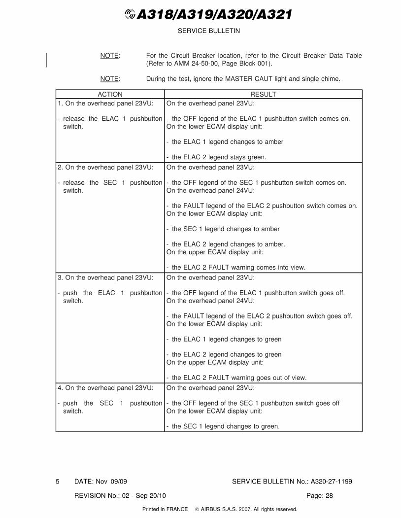
NOTE: For the Circuit Breaker location, refer to the Circuit Breaker Data Table(Refer to AMM 24-50-00, Page Block 001).
NOTE: During the test, ignore the MASTER CAUT light and single chime.
ACTION RESULT1. On the overhead panel 23VU:
- release the ELAC 1 pushbuttonswitch.
On the overhead panel 23VU:
- the OFF legend of the ELAC 1 pushbutton switch comes on.On the lower ECAM display unit:
- the ELAC 1 legend changes to amber
- the ELAC 2 legend stays green.
2. On the overhead panel 23VU:
- release the SEC 1 pushbuttonswitch.
On the overhead panel 23VU:
- the OFF legend of the SEC 1 pushbutton switch comes on.On the overhead panel 24VU:
- the FAULT legend of the ELAC 2 pushbutton switch comes on.On the lower ECAM display unit:
- the SEC 1 legend changes to amber
- the ELAC 2 legend changes to amber.On the upper ECAM display unit:
- the ELAC 2 FAULT warning comes into view.
3. On the overhead panel 23VU:
- push the ELAC 1 pushbuttonswitch.
On the overhead panel 23VU:
- the OFF legend of the ELAC 1 pushbutton switch goes off.On the overhead panel 24VU:
- the FAULT legend of the ELAC 2 pushbutton switch goes off.On the lower ECAM display unit:
- the ELAC 1 legend changes to green
- the ELAC 2 legend changes to greenOn the upper ECAM display unit:
- the ELAC 2 FAULT warning goes out of view.
4. On the overhead panel 23VU:
- push the SEC 1 pushbuttonswitch.
On the overhead panel 23VU:
- the OFF legend of the SEC 1 pushbutton switch goes offOn the lower ECAM display unit:
- the SEC 1 legend changes to green.
DATE: Nov 09/09 SERVICE BULLETIN No.: A320-27-1199
REVISION No.: 02 - Sep 20/10 Page: 28
5
Printed in FRANCE © AIRBUS S.A.S. 2007. All rights reserved.
@A318/A319/A320/A321SERVICE BULLETIN
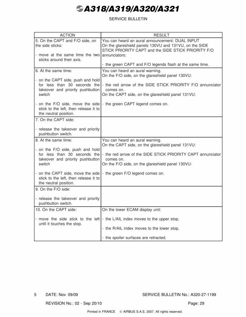
ACTION RESULT5. On the CAPT and F/O side, onthe side sticks:
- move at the same time the twosticks around their axis.
You can heard an aural announcement: DUAL INPUTOn the glareshield panels 130VU and 131VU, on the SIDESTICK PRIORITY CAPT and the SIDE STICK PRIORITY F/Oannunciators:
- the green CAPT and F/O legends flash at the same time.
6. At the same time:
- on the CAPT side, push and holdfor less than 30 seconds thetakeover and priority pushbuttonswitch
- on the F/O side, move the sidestick to the left, then release it tothe neutral position.
You can heard an aural warning.On the F/O side, on the glareshield panel 130VU:
- the red arrow of the SIDE STICK PRIORITY F/O annunciatorcomes on.
On the CAPT side, on the glareshield panel 131VU:
- the green CAPT legend comes on.
7. On the CAPT side:
- release the takeover and prioritypushbutton switch.
8. At the same time:
- on the F/O side, push and holdfor less than 30 seconds thetakeover and priority pushbuttonswitch
- on the CAPT side, move the sidestick to the left, then release it tothe neutral position.
You can heard an aural warning.On the CAPT side, on the glareshield panel 131VU:
- the red arrow of the SIDE STICK PRIORITY CAPT annunciatorcomes on.
On the F/O side, on the glareshield panel 130VU:
- the green F/O legend comes on.
9. On the F/O side:
- release the takeover and prioritypushbutton switch.
10. On the CAPT side:
- move the side stick to the leftuntil it touches the stop.
On the lower ECAM display unit:
- the L/AIL index moves to the upper stop,
- the R/AIL index moves to the lower stop,
- the spoiler surfaces are retracted.
DATE: Nov 09/09 SERVICE BULLETIN No.: A320-27-1199
REVISION No.: 02 - Sep 20/10 Page: 29
5
Printed in FRANCE © AIRBUS S.A.S. 2007. All rights reserved.
@A318/A319/A320/A321SERVICE BULLETIN
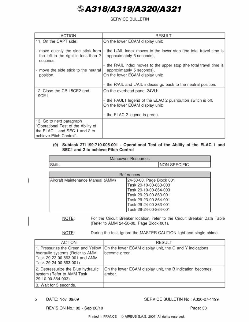
ACTION RESULT11. On the CAPT side:
- move quickly the side stick fromthe left to the right in less than 2seconds,
- move the side stick to the neutralposition.
On the lower ECAM display unit:
- the L/AIL index moves to the lower stop (the total travel time isapproximately 5 seconds),
- the R/AIL index moves to the upper stop (the total travel time isapproximately 5 seconds),
On the lower ECAM display unit:
- the R/AIL and L/AIL indexes go back to the neutral position.
12. Close the CB 15CE2 and19CE1
On the overhead panel 24VU:
- the FAULT legend of the ELAC 2 pushbutton switch is off.On the lower ECAM display unit:
- the ELAC 2 legend is green.
13. Go to next paragraph"Operational Test of the Ability ofthe ELAC 1 and SEC 1 and 2 toachieve Pitch Control".
(9) Subtask 271199-710-005-001 - Operational Test of the Ability of the ELAC 1 andSEC1 and 2 to achieve Pitch Control
Manpower Resources
Skills NON SPECIFIC
ReferencesAircraft Maintenance Manual (AMM) 24-50-00, Page Block 001
Task 29-10-00-863-003Task 29-10-00-864-003Task 29-23-00-863-001Task 29-23-00-864-001Task 29-24-00-863-001Task 29-24-00-864-001
NOTE: For the Circuit Breaker location, refer to the Circuit Breaker Data Table(Refer to AMM 24-50-00, Page Block 001).
NOTE: During the test, ignore the MASTER CAUTION light and single chime.
ACTION RESULT1. Pressurize the Green and Yellowhydraulic systems (Refer to AMMTask 29-23-00-863-001 and AMMTask 29-24-00-863-001)
On the lower ECAM display unit, the G and Y indicationsbecome green.
2. Depressurize the Blue hydraulicsystem (Refer to AMM Task29-10-00-864-003).
On the lower ECAM display unit, the B indication becomesamber.
3. Wait for 5 seconds.
DATE: Nov 09/09 SERVICE BULLETIN No.: A320-27-1199
REVISION No.: 02 - Sep 20/10 Page: 30
5
Printed in FRANCE © AIRBUS S.A.S. 2007. All rights reserved.
@A318/A319/A320/A321SERVICE BULLETIN
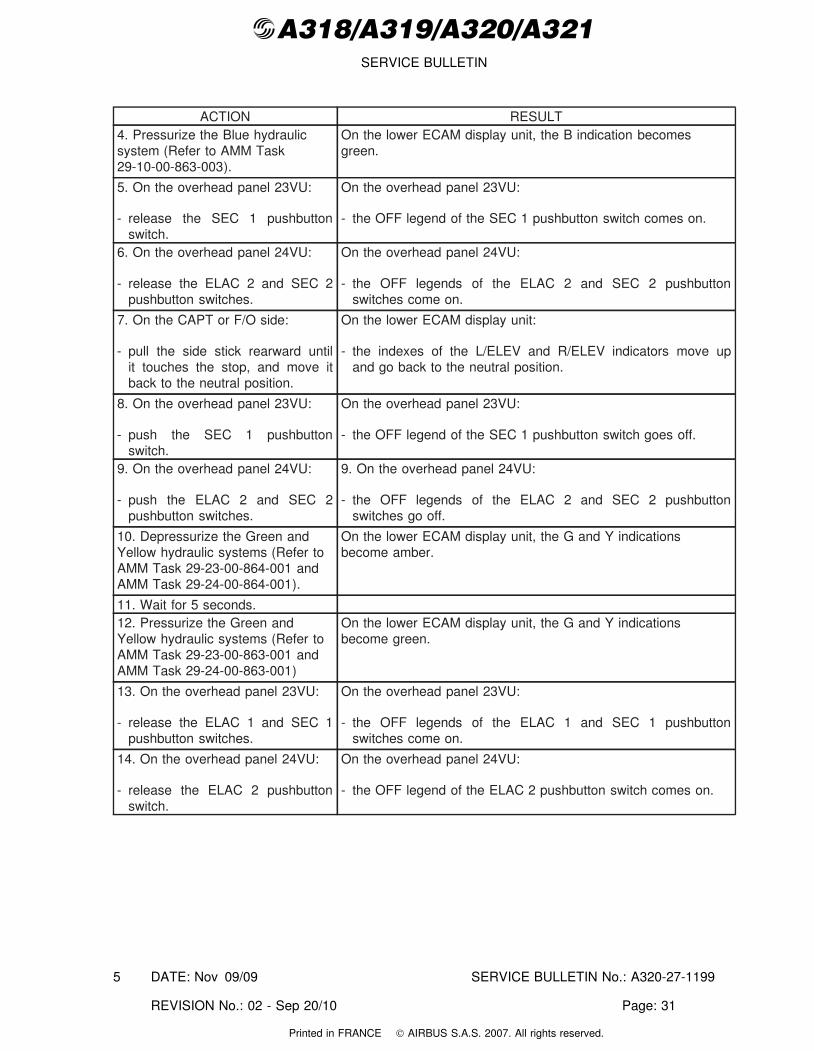
ACTION RESULT4. Pressurize the Blue hydraulicsystem (Refer to AMM Task29-10-00-863-003).
On the lower ECAM display unit, the B indication becomesgreen.
5. On the overhead panel 23VU:
- release the SEC 1 pushbuttonswitch.
On the overhead panel 23VU:
- the OFF legend of the SEC 1 pushbutton switch comes on.
6. On the overhead panel 24VU:
- release the ELAC 2 and SEC 2pushbutton switches.
On the overhead panel 24VU:
- the OFF legends of the ELAC 2 and SEC 2 pushbuttonswitches come on.
7. On the CAPT or F/O side:
- pull the side stick rearward untilit touches the stop, and move itback to the neutral position.
On the lower ECAM display unit:
- the indexes of the L/ELEV and R/ELEV indicators move upand go back to the neutral position.
8. On the overhead panel 23VU:
- push the SEC 1 pushbuttonswitch.
On the overhead panel 23VU:
- the OFF legend of the SEC 1 pushbutton switch goes off.
9. On the overhead panel 24VU:
- push the ELAC 2 and SEC 2pushbutton switches.
9. On the overhead panel 24VU:
- the OFF legends of the ELAC 2 and SEC 2 pushbuttonswitches go off.
10. Depressurize the Green andYellow hydraulic systems (Refer toAMM Task 29-23-00-864-001 andAMM Task 29-24-00-864-001).
On the lower ECAM display unit, the G and Y indicationsbecome amber.
11. Wait for 5 seconds.12. Pressurize the Green andYellow hydraulic systems (Refer toAMM Task 29-23-00-863-001 andAMM Task 29-24-00-863-001)
On the lower ECAM display unit, the G and Y indicationsbecome green.
13. On the overhead panel 23VU:
- release the ELAC 1 and SEC 1pushbutton switches.
On the overhead panel 23VU:
- the OFF legends of the ELAC 1 and SEC 1 pushbuttonswitches come on.
14. On the overhead panel 24VU:
- release the ELAC 2 pushbuttonswitch.
On the overhead panel 24VU:
- the OFF legend of the ELAC 2 pushbutton switch comes on.
DATE: Nov 09/09 SERVICE BULLETIN No.: A320-27-1199
REVISION No.: 02 - Sep 20/10 Page: 31
5
Printed in FRANCE © AIRBUS S.A.S. 2007. All rights reserved.
@A318/A319/A320/A321SERVICE BULLETIN
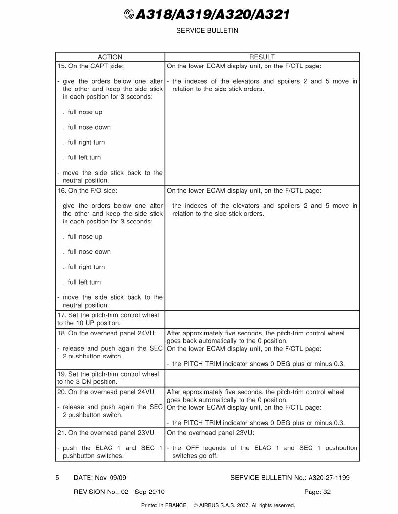
ACTION RESULT15. On the CAPT side:
- give the orders below one afterthe other and keep the side stickin each position for 3 seconds:
. full nose up
. full nose down
. full right turn
. full left turn
- move the side stick back to theneutral position.
On the lower ECAM display unit, on the F/CTL page:
- the indexes of the elevators and spoilers 2 and 5 move inrelation to the side stick orders.
16. On the F/O side:
- give the orders below one afterthe other and keep the side stickin each position for 3 seconds:
. full nose up
. full nose down
. full right turn
. full left turn
- move the side stick back to theneutral position.
On the lower ECAM display unit, on the F/CTL page:
- the indexes of the elevators and spoilers 2 and 5 move inrelation to the side stick orders.
17. Set the pitch-trim control wheelto the 10 UP position.
18. On the overhead panel 24VU:
- release and push again the SEC2 pushbutton switch.
After approximately five seconds, the pitch-trim control wheelgoes back automatically to the 0 position.On the lower ECAM display unit, on the F/CTL page:
- the PITCH TRIM indicator shows 0 DEG plus or minus 0.3.
19. Set the pitch-trim control wheelto the 3 DN position.
20. On the overhead panel 24VU:
- release and push again the SEC2 pushbutton switch.
After approximately five seconds, the pitch-trim control wheelgoes back automatically to the 0 position.On the lower ECAM display unit, on the F/CTL page:
- the PITCH TRIM indicator shows 0 DEG plus or minus 0.3.
21. On the overhead panel 23VU:
- push the ELAC 1 and SEC 1pushbutton switches.
On the overhead panel 23VU:
- the OFF legends of the ELAC 1 and SEC 1 pushbuttonswitches go off.
DATE: Nov 09/09 SERVICE BULLETIN No.: A320-27-1199
REVISION No.: 02 - Sep 20/10 Page: 32
5
Printed in FRANCE © AIRBUS S.A.S. 2007. All rights reserved.
@A318/A319/A320/A321SERVICE BULLETIN
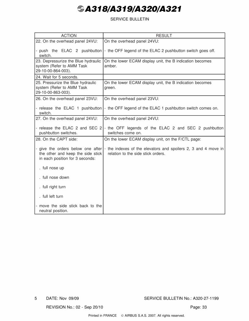
ACTION RESULT22. On the overhead panel 24VU:
- push the ELAC 2 pushbuttonswitch.
On the overhead panel 24VU:
- the OFF legend of the ELAC 2 pushbutton switch goes off.
23. Depressurize the Blue hydraulicsystem (Refer to AMM Task29-10-00-864-003).
On the lower ECAM display unit, the B indication becomesamber.
24. Wait for 5 seconds.25. Pressurize the Blue hydraulicsystem (Refer to AMM Task29-10-00-863-003).
On the lower ECAM display unit, the B indication becomesgreen.
26. On the overhead panel 23VU:
- release the ELAC 1 pushbuttonswitch.
On the overhead panel 23VU:
- the OFF legend of the ELAC 1 pushbutton switch comes on.
27. On the overhead panel 24VU:
- release the ELAC 2 and SEC 2pushbutton switches.
On the overhead panel 24VU:
- the OFF legends of the ELAC 2 and SEC 2 pushbuttonswitches come on.
28. On the CAPT side:
- give the orders below one afterthe other and keep the side stickin each position for 3 seconds:
. full nose up
. full nose down
. full right turn
. full left turn
- move the side stick back to theneutral position.
On the lower ECAM display unit, on the F/CTL page:
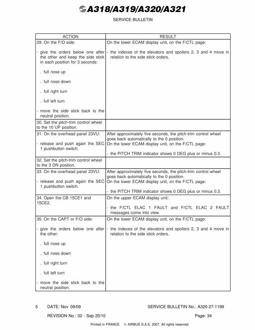
- the indexes of the elevators and spoilers 2, 3 and 4 move inrelation to the side stick orders.
DATE: Nov 09/09 SERVICE BULLETIN No.: A320-27-1199
REVISION No.: 02 - Sep 20/10 Page: 33
5
Printed in FRANCE © AIRBUS S.A.S. 2007. All rights reserved.
@A318/A319/A320/A321SERVICE BULLETIN
ACTION RESULT29. On the F/O side:
- give the orders below one afterthe other and keep the side stickin each position for 3 seconds:
. full nose up
. full nose down
. full right turn
. full left turn
- move the side stick back to theneutral position.
On the lower ECAM display unit, on the F/CTL page:
- the indexes of the elevators and spoilers 2, 3 and 4 move inrelation to the side stick orders.
30. Set the pitch-trim control wheelto the 10 UP position.
31. On the overhead panel 23VU:
- release and push again the SEC1 pushbutton switch.
After approximately five seconds, the pitch-trim control wheelgoes back automatically to the 0 position.On the lower ECAM display unit, on the F/CTL page:
- the PITCH TRIM indicator shows 0 DEG plus or minus 0.3.
32. Set the pitch-trim control wheelto the 3 DN position.
33. On the overhead panel 23VU:
- release and push again the SEC1 pushbutton switch.
After approximately five seconds, the pitch-trim control wheelgoes back automatically to the 0 position.On the lower ECAM display unit, on the F/CTL page:
- the PITCH TRIM indicator shows 0 DEG plus or minus 0.3.
34. Open the CB 15CE1 and15CE2.
On the upper ECAM display unit:
- the F/CTL ELAC 1 FAULT and F/CTL ELAC 2 FAULTmessages come into view.
35. On the CAPT or F/O side:
- give the orders below one afterthe other:
. full nose up
. full nose down
. full right turn
. full left turn
- move the side stick back to theneutral position.
On the lower ECAM display unit, on the F/CTL page:
- the indexes of the elevators and spoilers 2, 3 and 4 move inrelation to the side stick orders.
DATE: Nov 09/09 SERVICE BULLETIN No.: A320-27-1199
REVISION No.: 02 - Sep 20/10 Page: 34
5
Printed in FRANCE © AIRBUS S.A.S. 2007. All rights reserved.
@A318/A319/A320/A321SERVICE BULLETIN
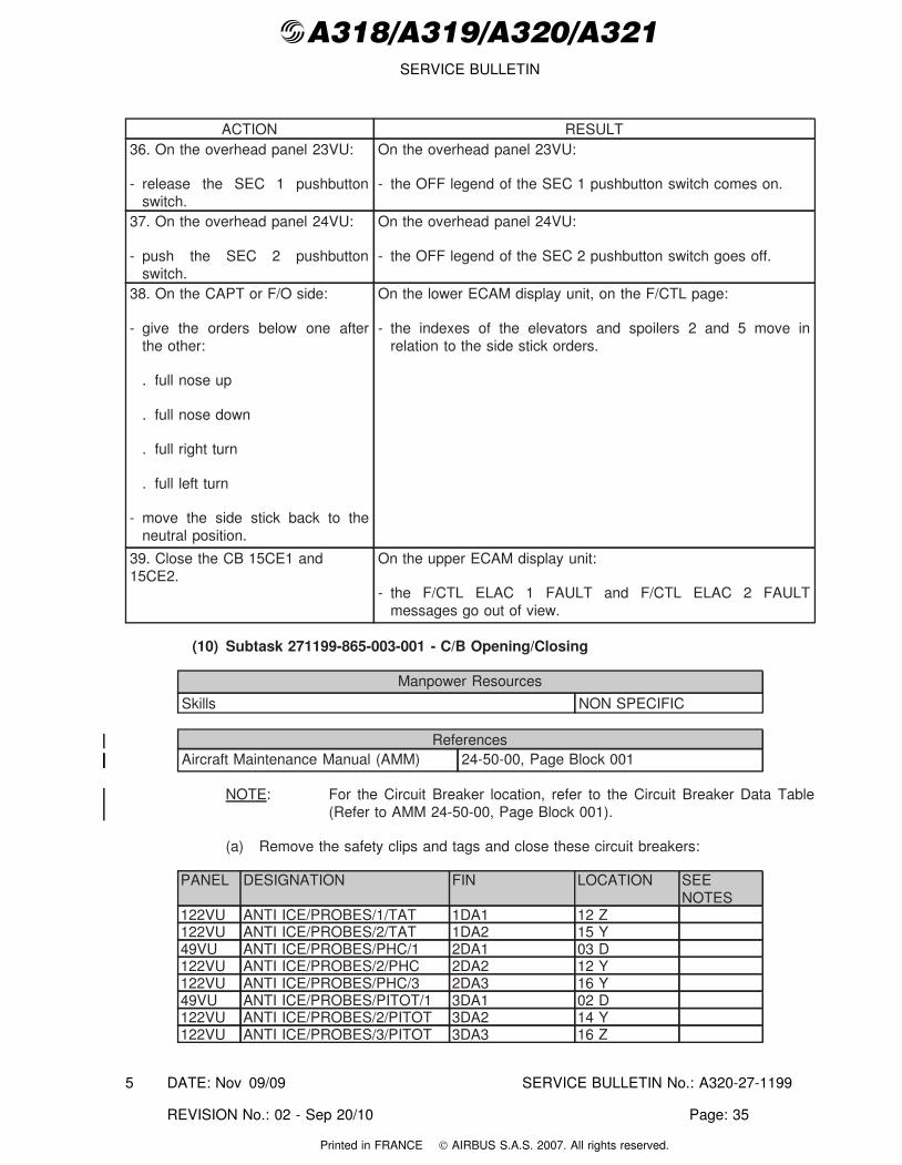
ACTION RESULT36. On the overhead panel 23VU:
- release the SEC 1 pushbuttonswitch.
On the overhead panel 23VU:
- the OFF legend of the SEC 1 pushbutton switch comes on.
37. On the overhead panel 24VU:
- push the SEC 2 pushbuttonswitch.
On the overhead panel 24VU:
- the OFF legend of the SEC 2 pushbutton switch goes off.
38. On the CAPT or F/O side:
- give the orders below one afterthe other:
. full nose up
. full nose down
. full right turn
. full left turn
- move the side stick back to theneutral position.
On the lower ECAM display unit, on the F/CTL page:
- the indexes of the elevators and spoilers 2 and 5 move inrelation to the side stick orders.
39. Close the CB 15CE1 and15CE2.
On the upper ECAM display unit:
- the F/CTL ELAC 1 FAULT and F/CTL ELAC 2 FAULTmessages go out of view.
(10) Subtask 271199-865-003-001 - C/B Opening/Closing
Manpower Resources
Skills NON SPECIFIC
ReferencesAircraft Maintenance Manual (AMM) 24-50-00, Page Block 001
NOTE: For the Circuit Breaker location, refer to the Circuit Breaker Data Table(Refer to AMM 24-50-00, Page Block 001).
(a) Remove the safety clips and tags and close these circuit breakers:
PANEL DESIGNATION FIN LOCATION SEENOTES
122VU ANTI ICE/PROBES/1/TAT 1DA1 12 Z122VU ANTI ICE/PROBES/2/TAT 1DA2 15 Y49VU ANTI ICE/PROBES/PHC/1 2DA1 03 D122VU ANTI ICE/PROBES/2/PHC 2DA2 12 Y122VU ANTI ICE/PROBES/PHC/3 2DA3 16 Y49VU ANTI ICE/PROBES/PITOT/1 3DA1 02 D122VU ANTI ICE/PROBES/2/PITOT 3DA2 14 Y122VU ANTI ICE/PROBES/3/PITOT 3DA3 16 Z
DATE: Nov 09/09 SERVICE BULLETIN No.: A320-27-1199
REVISION No.: 02 - Sep 20/10 Page: 35
5
Printed in FRANCE © AIRBUS S.A.S. 2007. All rights reserved.
@A318/A319/A320/A321SERVICE BULLETIN
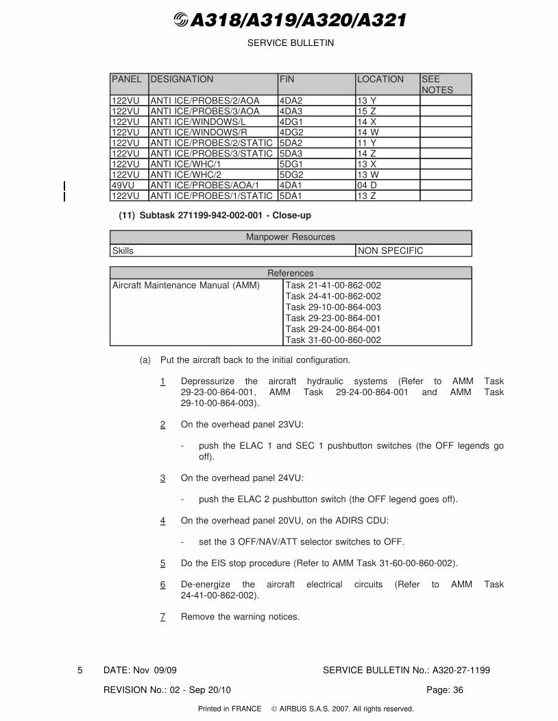
PANEL DESIGNATION FIN LOCATION SEENOTES
122VU ANTI ICE/PROBES/2/AOA 4DA2 13 Y122VU ANTI ICE/PROBES/3/AOA 4DA3 15 Z122VU ANTI ICE/WINDOWS/L 4DG1 14 X122VU ANTI ICE/WINDOWS/R 4DG2 14 W122VU ANTI ICE/PROBES/2/STATIC 5DA2 11 Y122VU ANTI ICE/PROBES/3/STATIC 5DA3 14 Z122VU ANTI ICE/WHC/1 5DG1 13 X122VU ANTI ICE/WHC/2 5DG2 13 W49VU ANTI ICE/PROBES/AOA/1 4DA1 04 D122VU ANTI ICE/PROBES/1/STATIC 5DA1 13 Z
(11) Subtask 271199-942-002-001 - Close-up
Manpower Resources
Skills NON SPECIFIC
ReferencesAircraft Maintenance Manual (AMM) Task 21-41-00-862-002
Task 24-41-00-862-002Task 29-10-00-864-003Task 29-23-00-864-001Task 29-24-00-864-001Task 31-60-00-860-002
(a) Put the aircraft back to the initial configuration.
1 Depressurize the aircraft hydraulic systems (Refer to AMM Task29-23-00-864-001, AMM Task 29-24-00-864-001 and AMM Task29-10-00-864-003).
2 On the overhead panel 23VU:
- push the ELAC 1 and SEC 1 pushbutton switches (the OFF legends gooff).
3 On the overhead panel 24VU:
- push the ELAC 2 pushbutton switch (the OFF legend goes off).
4 On the overhead panel 20VU, on the ADIRS CDU:
- set the 3 OFF/NAV/ATT selector switches to OFF.
5 Do the EIS stop procedure (Refer to AMM Task 31-60-00-860-002).
6 De-energize the aircraft electrical circuits (Refer to AMM Task24-41-00-862-002).
7 Remove the warning notices.
DATE: Nov 09/09 SERVICE BULLETIN No.: A320-27-1199
REVISION No.: 02 - Sep 20/10 Page: 36
5
Printed in FRANCE © AIRBUS S.A.S. 2007. All rights reserved.
@A318/A319/A320/A321SERVICE BULLETIN
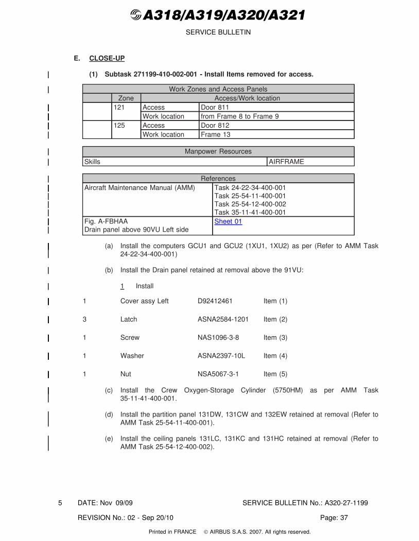
E. CLOSE-UP
(1) Subtask 271199-410-002-001 - Install Items removed for access.
Work Zones and Access PanelsZone Access/Work location
121 Access Door 811Work location from Frame 8 to Frame 9
125 Access Door 812Work location Frame 13
Manpower Resources
Skills AIRFRAME
ReferencesAircraft Maintenance Manual (AMM) Task 24-22-34-400-001
Task 25-54-11-400-001Task 25-54-12-400-002Task 35-11-41-400-001
Fig. A-FBHAADrain panel above 90VU Left side
Sheet 01
(a) Install the computers GCU1 and GCU2 (1XU1, 1XU2) as per (Refer to AMM Task24-22-34-400-001)
(b) Install the Drain panel retained at removal above the 91VU:
1 Install
1 Cover assy Left D92412461 Item (1)
3 Latch ASNA2584-1201 Item (2)
1 Screw NAS1096-3-8 Item (3)
1 Washer ASNA2397-10L Item (4)
1 Nut NSA5067-3-1 Item (5)
(c) Install the Crew Oxygen-Storage Cylinder (5750HM) as per AMM Task35-11-41-400-001.
(d) Install the partition panel 131DW, 131CW and 132EW retained at removal (Refer toAMM Task 25-54-11-400-001).
(e) Install the ceiling panels 131LC, 131KC and 131HC retained at removal (Refer toAMM Task 25-54-12-400-002).
DATE: Nov 09/09 SERVICE BULLETIN No.: A320-27-1199
REVISION No.: 02 - Sep 20/10 Page: 37
5
Printed in FRANCE © AIRBUS S.A.S. 2007. All rights reserved.
@A318/A319/A320/A321SERVICE BULLETIN
(2) Subtask 271199-942-001-001 - Close-up
Manpower Resources
Skills NON SPECIFIC
ReferencesAircraft Maintenance Manual (AMM) Task 52-10-00-410-001
52-30-00, Page Block 201Task 52-41-00-410-002
(a) Make sure that the work areas are clean and clear of tools and other items ofequipment.
(b) On the battery power center 105VU, install the protective cover and tighten the twoscrews.
(c) Close the FWD cargo compartment door 825 (Refer to AMM 52-30-00, Page Block201).
(d) Close the FWD avionics compartment lateral doors 812, 822 and 824 (Refer toAMM Task 52-41-00-410-002).
(e) Close the FWD avionics compartment door 811 (Refer to AMM Task52-41-00-410-002).
(f) Close the passenger/crew doors (Refer to AMM Task 52-10-00-410-001).
(g) Remove the access platform.
DATE: Nov 09/09 SERVICE BULLETIN No.: A320-27-1199
REVISION No.: 02 - Sep 20/10 Page: 38
5
Printed in FRANCE © AIRBUS S.A.S. 2007. All rights reserved.
@A318/A319/A320/A321SERVICE BULLETIN
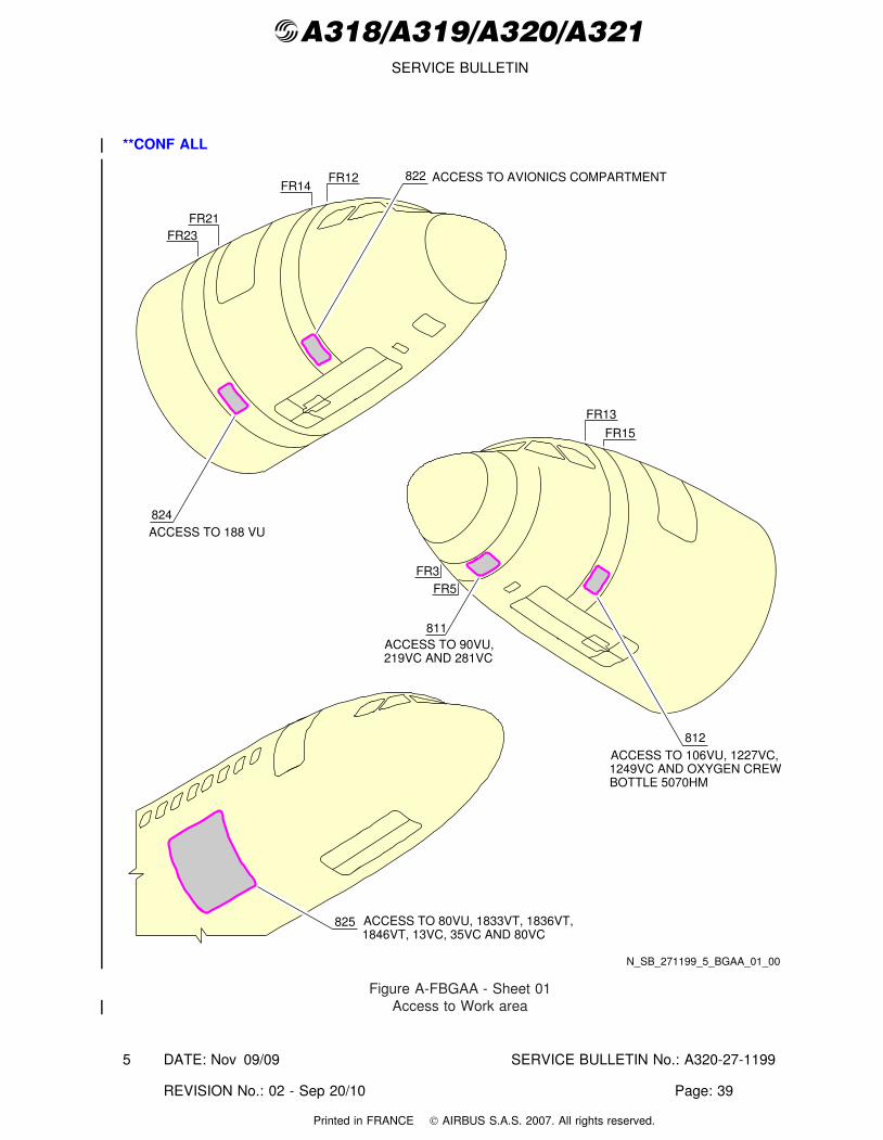
**CONF ALL
N_SB_271199_5_BGAA_01_00
FR23FR21
FR3FR5
FR15
FR13
FR14FR12
824ACCESS TO 188 VU
ACCESS TO AVIONICS COMPARTMENT
ACCESS TO 106VU, 1227VC,1249VC AND OXYGEN CREWBOTTLE 5070HM
825 ACCESS TO 80VU, 1833VT, 1836VT,1846VT, 13VC, 35VC AND 80VC
811ACCESS TO 90VU,219VC AND 281VC
822
812
Figure A-FBGAA - Sheet 01Access to Work area
DATE: Nov 09/09 SERVICE BULLETIN No.: A320-27-1199
REVISION No.: 02 - Sep 20/10 Page: 39
5
Printed in FRANCE © AIRBUS S.A.S. 2007. All rights reserved.
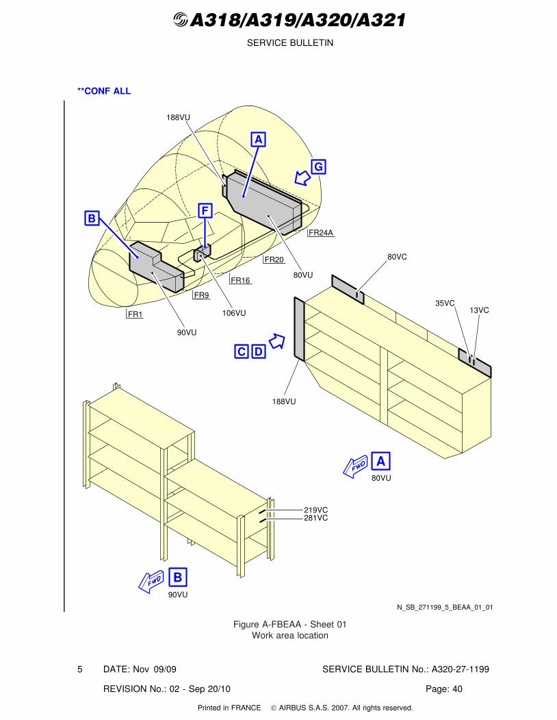
@A318/A319/A320/A321SERVICE BULLETIN
**CONF ALL
80VU
90VU
80VC
35VC
219VC
188VU
B
C D
A
N_SB_271199_5_BEAA_01_01
188VU
80VU
106VU
90VU
FR1
FR20
FR16
FR9
FR24A
A
BF
G
13VC
281VC
Figure A-FBEAA - Sheet 01Work area location
DATE: Nov 09/09 SERVICE BULLETIN No.: A320-27-1199
REVISION No.: 02 - Sep 20/10 Page: 40
5
Printed in FRANCE © AIRBUS S.A.S. 2007. All rights reserved.
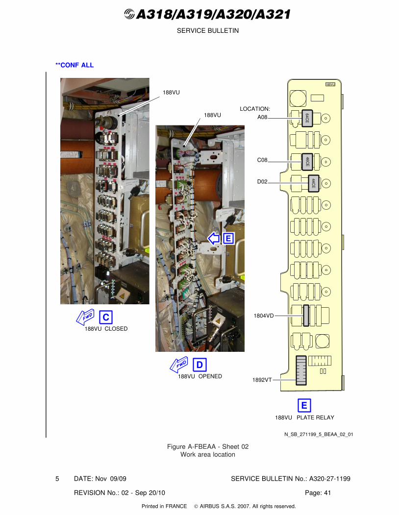
@A318/A319/A320/A321SERVICE BULLETIN
**CONF ALL
PLATE RELAY188VU
LOCATION:
A08
C08
D02
188VU
64CE
46CE
44CE
188VU
188VU
C
D
E
188VU CLOSED
OPENED188VU
N_SB_271199_5_BEAA_02_01
E
1804VD
1892VT
Figure A-FBEAA - Sheet 02Work area location
DATE: Nov 09/09 SERVICE BULLETIN No.: A320-27-1199
REVISION No.: 02 - Sep 20/10 Page: 41
5
Printed in FRANCE © AIRBUS S.A.S. 2007. All rights reserved.
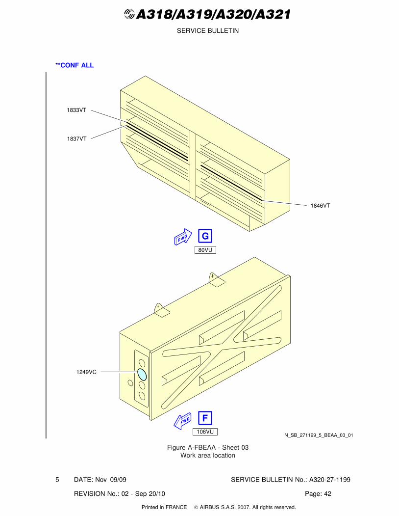
@A318/A319/A320/A321SERVICE BULLETIN
**CONF ALL
N_SB_271199_5_BEAA_03_01
80VU
106VU
1249VC
1833VT
1837VT
1846VT
G
F
Figure A-FBEAA - Sheet 03Work area location
DATE: Nov 09/09 SERVICE BULLETIN No.: A320-27-1199
REVISION No.: 02 - Sep 20/10 Page: 42
5
Printed in FRANCE © AIRBUS S.A.S. 2007. All rights reserved.
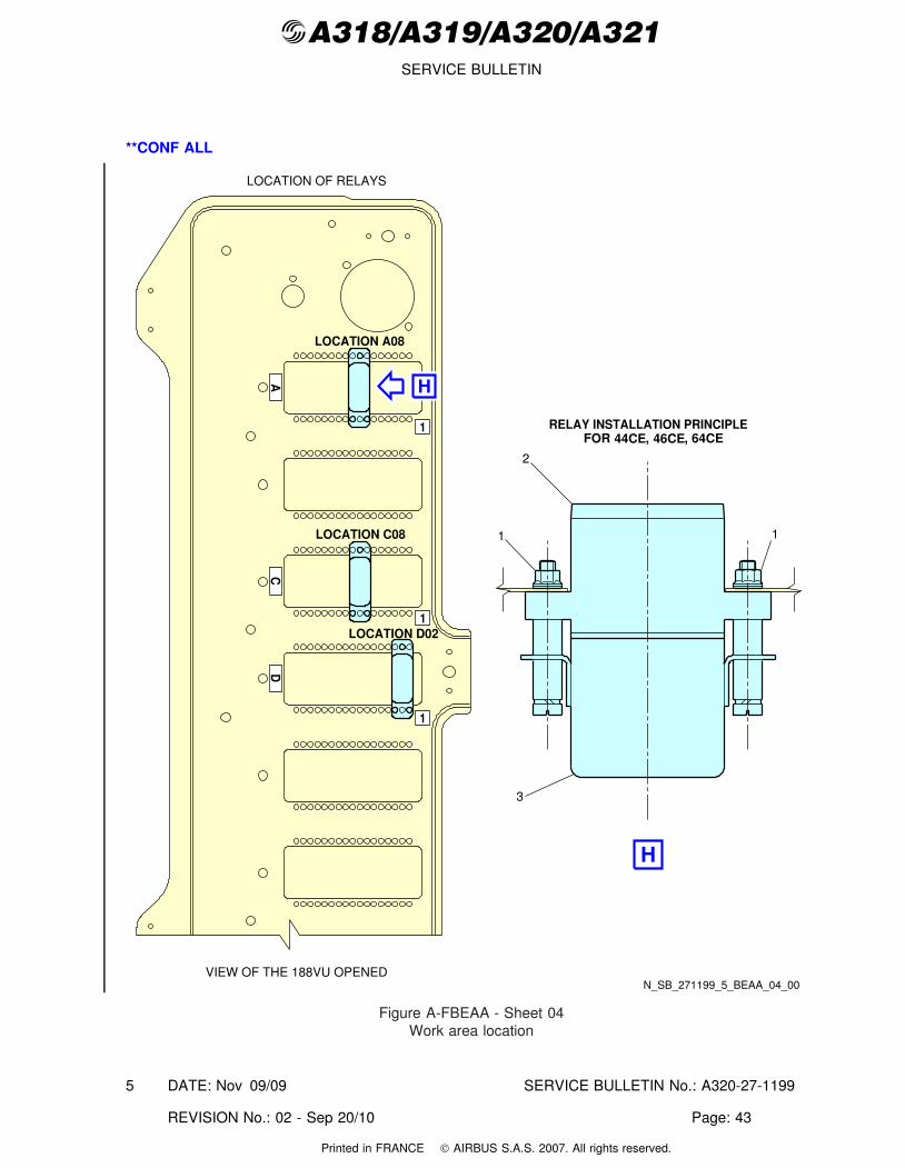
@A318/A319/A320/A321SERVICE BULLETIN
**CONF ALL
RELAY INSTALLATION PRINCIPLE44CE 46CE 64CEFOR , ,
LOCATION OF RELAYS
N_SB_271199_5_BEAA_04_00VIEW OF THE 188VU OPENED
DC
A
1
1
1
LOCATION A08
LOCATION C08
LOCATION D02
1
2
1
3
H
H
Figure A-FBEAA - Sheet 04Work area location
DATE: Nov 09/09 SERVICE BULLETIN No.: A320-27-1199
REVISION No.: 02 - Sep 20/10 Page: 43
5
Printed in FRANCE © AIRBUS S.A.S. 2007. All rights reserved.
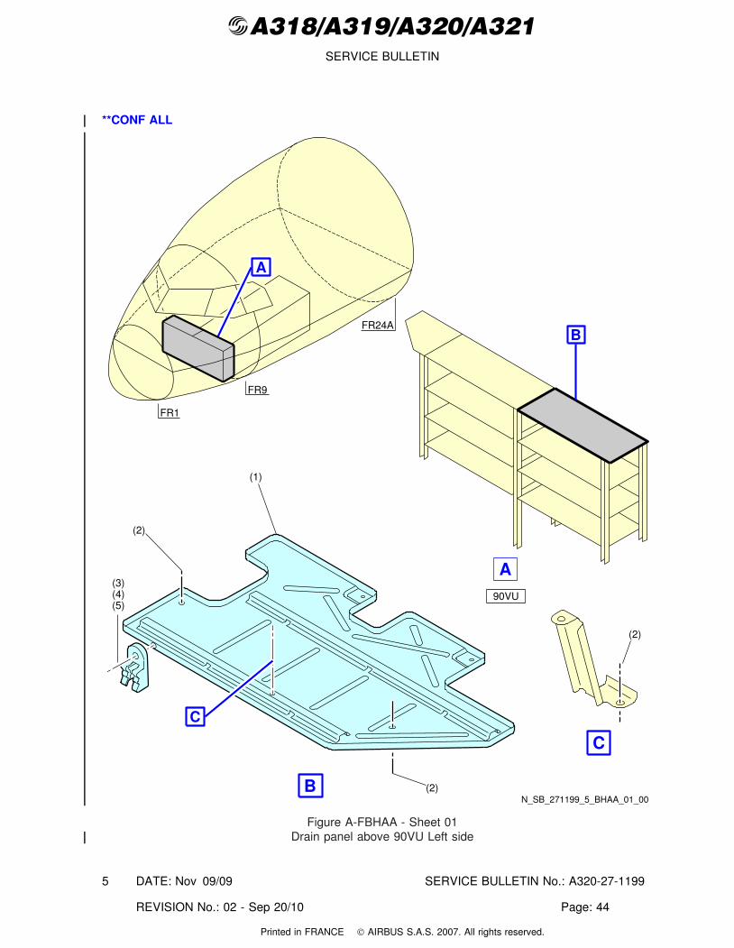
@A318/A319/A320/A321SERVICE BULLETIN
**CONF ALL
FR9
FR1
N_SB_271199_5_BHAA_01_00
A
FR24A
90VU
B
A(3)(4)(5)
(1)
(2)
(2)B
C
(2)
C
Figure A-FBHAA - Sheet 01Drain panel above 90VU Left side
DATE: Nov 09/09 SERVICE BULLETIN No.: A320-27-1199
REVISION No.: 02 - Sep 20/10 Page: 44
5
Printed in FRANCE © AIRBUS S.A.S. 2007. All rights reserved.
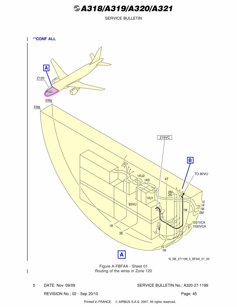
@A318/A319/A320/A321SERVICE BULLETIN
**CONF ALL
N_SB_271199_5_BFAA_01_00
93VU
1XU1
1XU21XS 4T
2M2S
1M
1E1P
1M2M
1031VCA1033VCA1R
3E
1M1S
Z120
A
FR8
FR9
219VC
A
B
TO 80VU
Figure A-FBFAA - Sheet 01Routing of the wires in Zone 120
DATE: Nov 09/09 SERVICE BULLETIN No.: A320-27-1199
REVISION No.: 02 - Sep 20/10 Page: 45
5
Printed in FRANCE © AIRBUS S.A.S. 2007. All rights reserved.
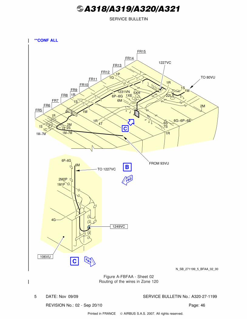
@A318/A319/A320/A321SERVICE BULLETIN
**CONF ALL
6P−6G6M
2M2P
1M1P
4G
1S1C
1M−7M
1S 2S2M
1R
1G1P
1R
1S1M1231VN
6P−6G6M
1XE
2M
22LS5XH1R
1S
1M
1R4T
6G−6P−6E6S7S
1R
1249VC
N_SB_271199_5_BFAA_02_00
FR15
FR14
FR12
FR13
FR11
FR10
FR9
FR8
FR7FR6
FR5
1M−7M
B
C
106VU
C
FROM 93VU
TO 80VU
TO 1227VC
1227VC
Figure A-FBFAA - Sheet 02Routing of the wires in Zone 120
DATE: Nov 09/09 SERVICE BULLETIN No.: A320-27-1199
REVISION No.: 02 - Sep 20/10 Page: 46
5
Printed in FRANCE © AIRBUS S.A.S. 2007. All rights reserved.
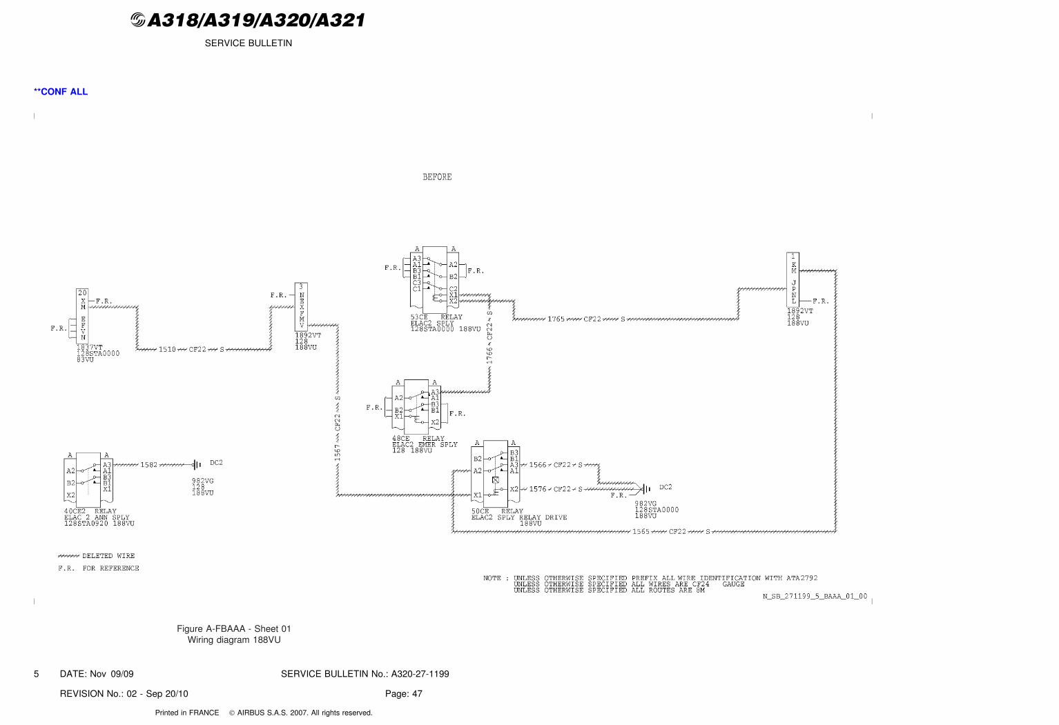
@A318/A319/A320/A321SERVICE BULLETIN
**CONF ALL
Figure A-FBAAA - Sheet 01Wiring diagram 188VU
DATE: Nov 09/09 SERVICE BULLETIN No.: A320-27-1199
REVISION No.: 02 - Sep 20/10 Page: 47
5
Printed in FRANCE © AIRBUS S.A.S. 2007. All rights reserved.
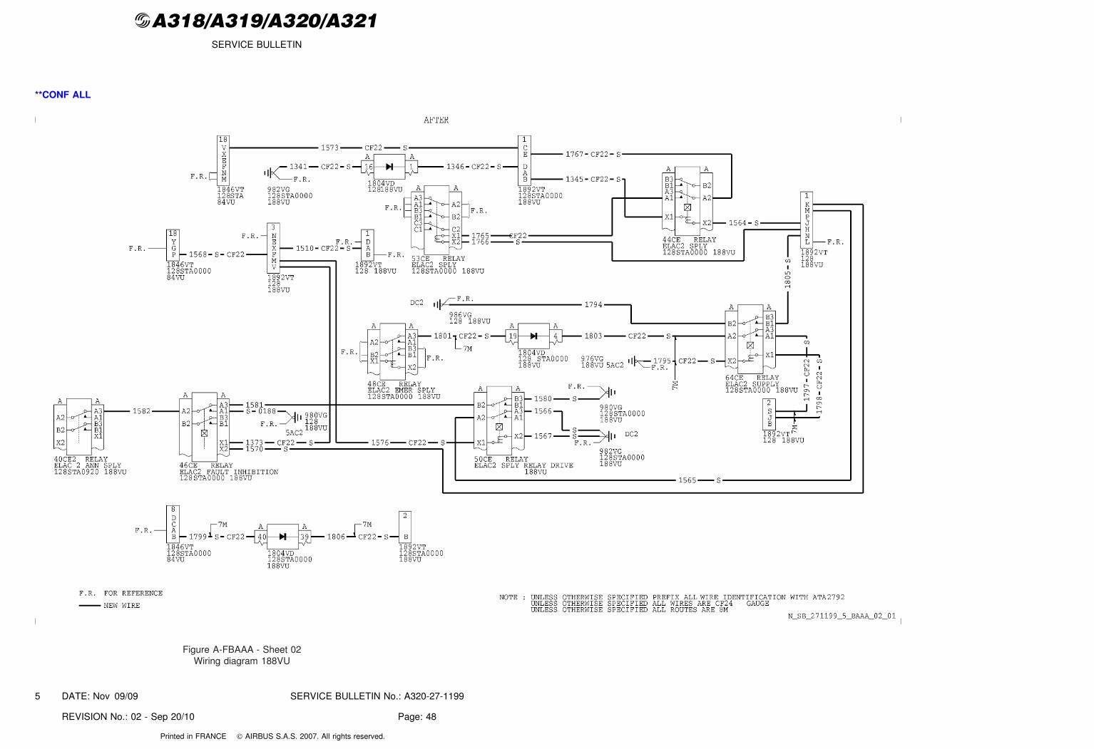
@A318/A319/A320/A321SERVICE BULLETIN
**CONF ALL
Figure A-FBAAA - Sheet 02Wiring diagram 188VU
DATE: Nov 09/09 SERVICE BULLETIN No.: A320-27-1199
REVISION No.: 02 - Sep 20/10 Page: 48
5
Printed in FRANCE © AIRBUS S.A.S. 2007. All rights reserved.
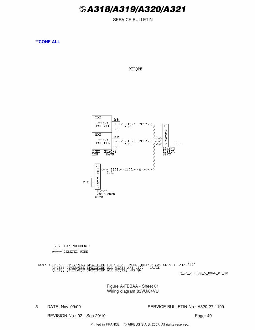
@A318/A319/A320/A321SERVICE BULLETIN
**CONF ALL
Figure A-FBBAA - Sheet 01Wiring diagram 83VU/84VU
DATE: Nov 09/09 SERVICE BULLETIN No.: A320-27-1199
REVISION No.: 02 - Sep 20/10 Page: 49
5
Printed in FRANCE © AIRBUS S.A.S. 2007. All rights reserved.
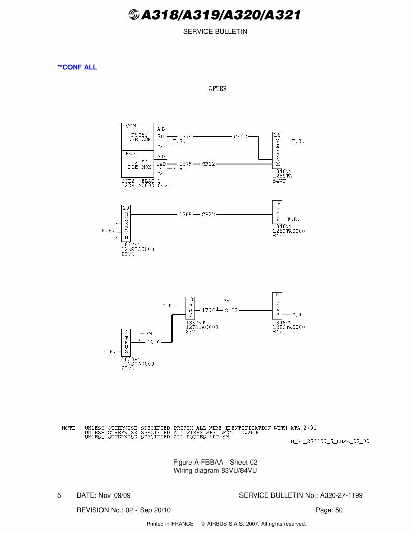
@A318/A319/A320/A321SERVICE BULLETIN
**CONF ALL
Figure A-FBBAA - Sheet 02Wiring diagram 83VU/84VU
DATE: Nov 09/09 SERVICE BULLETIN No.: A320-27-1199
REVISION No.: 02 - Sep 20/10 Page: 50
5
Printed in FRANCE © AIRBUS S.A.S. 2007. All rights reserved.
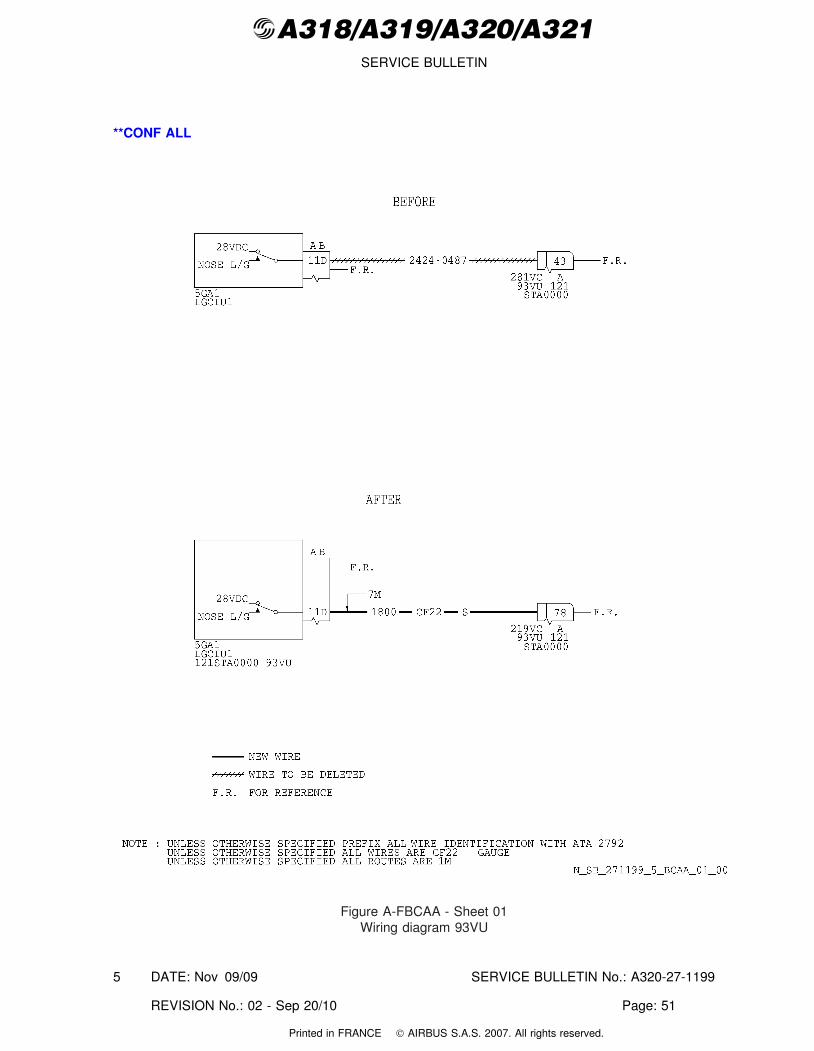
@A318/A319/A320/A321SERVICE BULLETIN
**CONF ALL
Figure A-FBCAA - Sheet 01Wiring diagram 93VU
DATE: Nov 09/09 SERVICE BULLETIN No.: A320-27-1199
REVISION No.: 02 - Sep 20/10 Page: 51
5
Printed in FRANCE © AIRBUS S.A.S. 2007. All rights reserved.
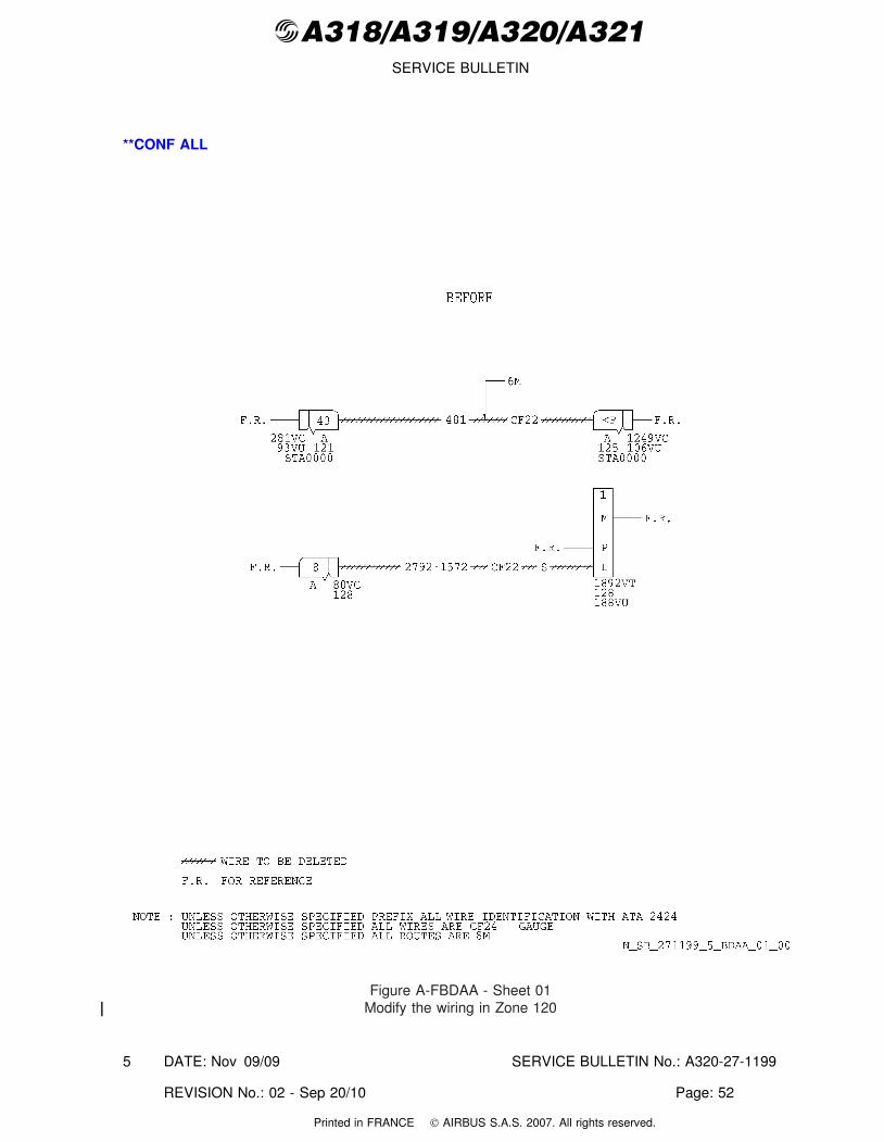
@A318/A319/A320/A321SERVICE BULLETIN
**CONF ALL
Figure A-FBDAA - Sheet 01Modify the wiring in Zone 120
DATE: Nov 09/09 SERVICE BULLETIN No.: A320-27-1199
REVISION No.: 02 - Sep 20/10 Page: 52
5
Printed in FRANCE © AIRBUS S.A.S. 2007. All rights reserved.
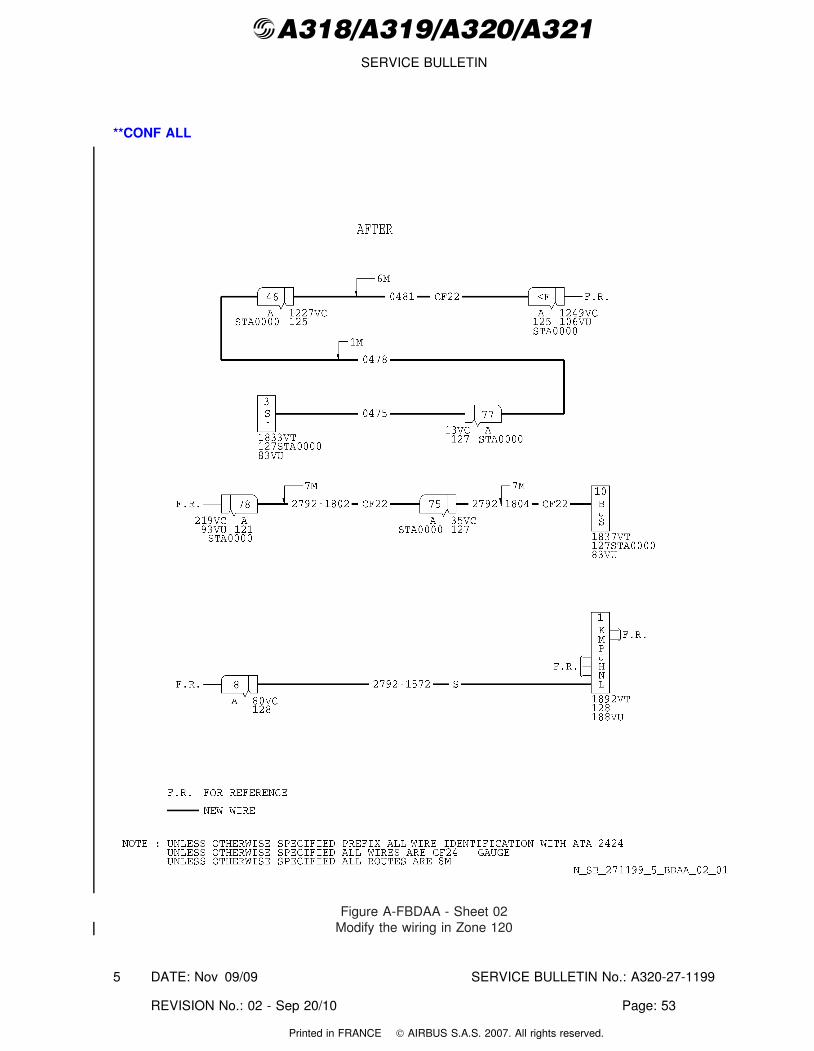
@A318/A319/A320/A321SERVICE BULLETIN
**CONF ALL
Figure A-FBDAA - Sheet 02Modify the wiring in Zone 120
DATE: Nov 09/09 SERVICE BULLETIN No.: A320-27-1199
REVISION No.: 02 - Sep 20/10 Page: 53
5
Printed in FRANCE © AIRBUS S.A.S. 2007. All rights reserved.
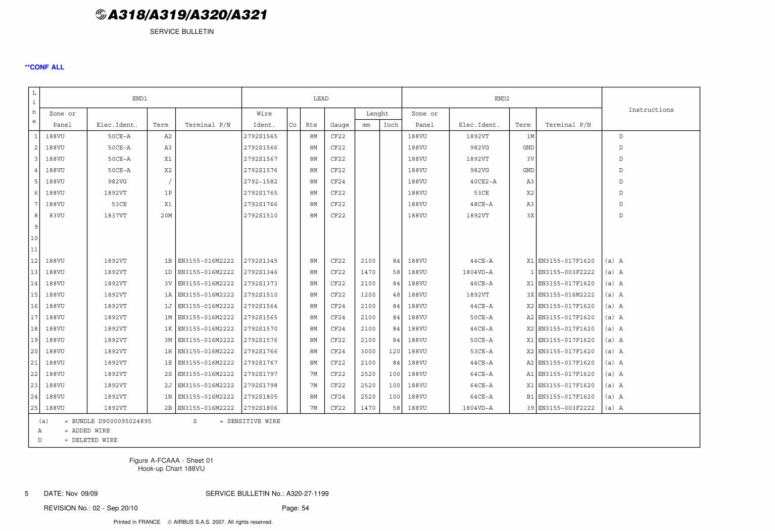
@A318/A319/A320/A321SERVICE BULLETIN
**CONF ALL
END1 LEAD END2
InstructionsZone or
Panel Elec.Ident. Term Terminal P/N
Wire
Ident. Co Rte Gauge
Lenght
mm Inch
Zone or
Panel Elec.Ident. Term Terminal P/N
L
i
n
e
1 188VU 50CE−A A2 2792S1565 8M CF22 188VU 1892VT 1M D
2 188VU 50CE−A A3 2792S1566 8M CF22 188VU 982VG GND D
3 188VU 50CE−A X1 2792S1567 8M CF22 188VU 1892VT 3V D
4 188VU 50CE−A X2 2792S1576 8M CF22 188VU 982VG GND D
5 188VU 982VG / 2792−1582 8M CF24 188VU 40CE2−A A3 D
6 188VU 1892VT 1P 2792S1765 8M CF22 188VU 53CE X2 D
7 188VU 53CE X1 2792S1766 8M CF22 188VU 48CE−A A3 D
8 83VU 1837VT 20M 2792S1510 8M CF22 188VU 1892VT 3X D
9
10
11
12 188VU 1892VT 1B EN3155−016M2222 2792S1345 8M CF22 2100 84 188VU 44CE−A X1 EN3155−017F1620 (a) A
13 188VU 1892VT 1D EN3155−016M2222 2792S1346 8M CF22 1470 58 188VU 1804VD−A 1 EN3155−003F2222 (a) A
14 188VU 1892VT 3V EN3155−016M2222 2792S1373 8M CF22 2100 84 188VU 46CE−A X1 EN3155−017F1620 (a) A
15 188VU 1892VT 1A EN3155−016M2222 2792S1510 8M CF22 1200 48 188VU 1892VT 3X EN3155−016M2222 (a) A
16 188VU 1892VT 1J EN3155−016M2222 2792S1564 8M CF24 2100 84 188VU 44CE−A X2 EN3155−017F1620 (a) A
17 188VU 1892VT 1M EN3155−016M2222 2792S1565 8M CF24 2100 84 188VU 50CE−A A2 EN3155−017F1620 (a) A
18 188VU 1892VT 1K EN3155−016M2222 2792S1570 8M CF24 2100 84 188VU 46CE−A X2 EN3155−017F1620 (a) A
19 188VU 1892VT 3M EN3155−016M2222 2792S1576 8M CF22 2100 84 188VU 50CE−A X1 EN3155−017F1620 (a) A
20 188VU 1892VT 1H EN3155−016M2222 2792S1766 8M CF24 3000 120 188VU 53CE−A X2 EN3155−017F1620 (a) A
21 188VU 1892VT 1E EN3155−016M2222 2792S1767 8M CF22 2100 84 188VU 44CE−A A2 EN3155−017F1620 (a) A
22 188VU 1892VT 2S EN3155−016M2222 2792S1797 7M CF22 2520 100 188VU 64CE−A A1 EN3155−017F1620 (a) A
23 188VU 1892VT 2J EN3155−016M2222 2792S1798 7M CF22 2520 100 188VU 64CE−A X1 EN3155−017F1620 (a) A
24 188VU 1892VT 1N EN3155−016M2222 2792S1805 8M CF24 2520 100 188VU 64CE−A B1 EN3155−017F1620 (a) A
25 188VU 1892VT 2B EN3155−016M2222 2792S1806 7M CF22 1470 58 188VU 1804VD−A 39 EN3155−003F2222 (a) A
(a) = BUNDLE D9000095024895 S = SENSITIVE WIRE
A = ADDED WIRE
D = DELETED WIRE
Figure A-FCAAA - Sheet 01Hook-up Chart 188VU
DATE: Nov 09/09 SERVICE BULLETIN No.: A320-27-1199
REVISION No.: 02 - Sep 20/10 Page: 54
5
Printed in FRANCE © AIRBUS S.A.S. 2007. All rights reserved.
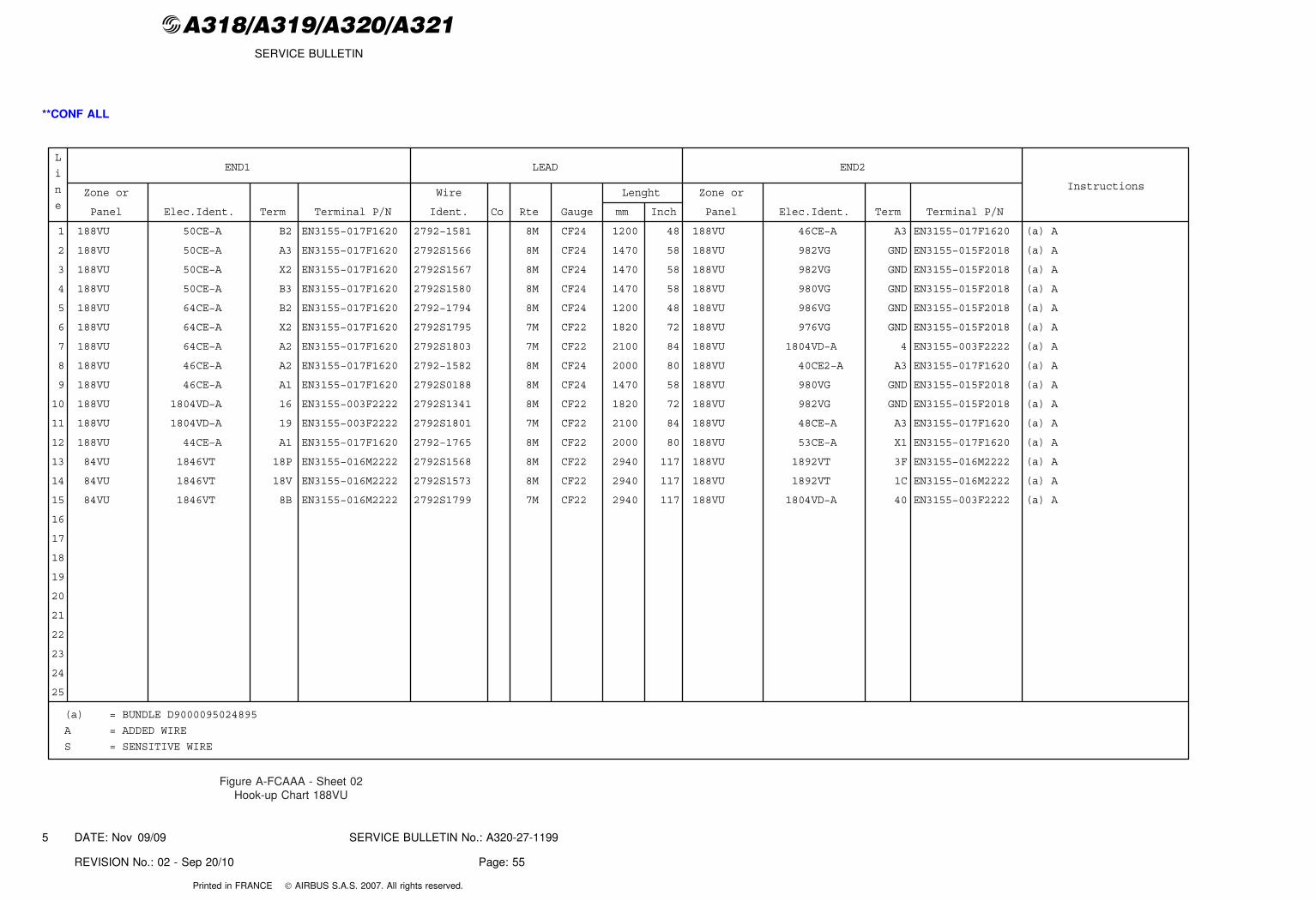
@A318/A319/A320/A321SERVICE BULLETIN
**CONF ALL
END1 LEAD END2
InstructionsZone or
Panel Elec.Ident. Term Terminal P/N
Wire
Ident. Co Rte Gauge
Lenght
mm Inch
Zone or
Panel Elec.Ident. Term Terminal P/N
L
i
n
e
1 188VU 50CE−A B2 EN3155−017F1620 2792−1581 8M CF24 1200 48 188VU 46CE−A A3 EN3155−017F1620 (a) A
2 188VU 50CE−A A3 EN3155−017F1620 2792S1566 8M CF24 1470 58 188VU 982VG GND EN3155−015F2018 (a) A
3 188VU 50CE−A X2 EN3155−017F1620 2792S1567 8M CF24 1470 58 188VU 982VG GND EN3155−015F2018 (a) A
4 188VU 50CE−A B3 EN3155−017F1620 2792S1580 8M CF24 1470 58 188VU 980VG GND EN3155−015F2018 (a) A
5 188VU 64CE−A B2 EN3155−017F1620 2792−1794 8M CF24 1200 48 188VU 986VG GND EN3155−015F2018 (a) A
6 188VU 64CE−A X2 EN3155−017F1620 2792S1795 7M CF22 1820 72 188VU 976VG GND EN3155−015F2018 (a) A
7 188VU 64CE−A A2 EN3155−017F1620 2792S1803 7M CF22 2100 84 188VU 1804VD−A 4 EN3155−003F2222 (a) A
8 188VU 46CE−A A2 EN3155−017F1620 2792−1582 8M CF24 2000 80 188VU 40CE2−A A3 EN3155−017F1620 (a) A
9 188VU 46CE−A A1 EN3155−017F1620 2792S0188 8M CF24 1470 58 188VU 980VG GND EN3155−015F2018 (a) A
10 188VU 1804VD−A 16 EN3155−003F2222 2792S1341 8M CF22 1820 72 188VU 982VG GND EN3155−015F2018 (a) A
11 188VU 1804VD−A 19 EN3155−003F2222 2792S1801 7M CF22 2100 84 188VU 48CE−A A3 EN3155−017F1620 (a) A
12 188VU 44CE−A A1 EN3155−017F1620 2792−1765 8M CF22 2000 80 188VU 53CE−A X1 EN3155−017F1620 (a) A
13 84VU 1846VT 18P EN3155−016M2222 2792S1568 8M CF22 2940 117 188VU 1892VT 3F EN3155−016M2222 (a) A
14 84VU 1846VT 18V EN3155−016M2222 2792S1573 8M CF22 2940 117 188VU 1892VT 1C EN3155−016M2222 (a) A
15 84VU 1846VT 8B EN3155−016M2222 2792S1799 7M CF22 2940 117 188VU 1804VD−A 40 EN3155−003F2222 (a) A
16
17
18
19
20
21
22
23
24
25
(a) = BUNDLE D9000095024895
A = ADDED WIRE
S = SENSITIVE WIRE
Figure A-FCAAA - Sheet 02Hook-up Chart 188VU
DATE: Nov 09/09 SERVICE BULLETIN No.: A320-27-1199
REVISION No.: 02 - Sep 20/10 Page: 55
5
Printed in FRANCE © AIRBUS S.A.S. 2007. All rights reserved.
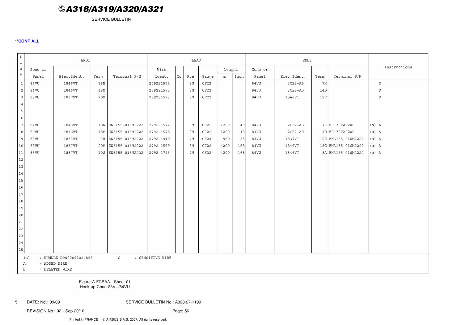
@A318/A319/A320/A321SERVICE BULLETIN
**CONF ALL
END1 LEAD END2
InstructionsZone or
Panel Elec.Ident. Term Terminal P/N
Wire
Ident. Co Rte Gauge
Lenght
mm Inch
Zone or
Panel Elec.Ident. Term Terminal P/N
L
i
n
e
1 84VU 1846VT 18N 2792S1574 8M CF22 84VU 2CE2−AB 7H D
2 84VU 1846VT 18M 2792S1575 8M CF22 84VU 2CE2−AD 14D D
3 83VU 1837VT 20X 2792S1573 8M CF22 84VU 1846VT 18V D
4
5
6
7 84VU 1846VT 18N EN3155−016M2222 2792−1574 8M CF22 1200 48 84VU 2CE2−AB 7H E0170FA2200 (a) A
8 84VU 1846VT 18M EN3155−016M2222 2792−1575 8M CF22 1200 48 84VU 2CE2−AD 14D E0170FA2200 (a) A
9 83VU 1833VT 3R EN3155−016M2222 2792−1910 7M CF24 950 38 83VU 1837VT 10S EN3155−016M2222 (a) A
10 83VU 1837VT 20M EN3155−016M2222 2792−1569 8M CF22 4200 168 84VU 1846VT 18G EN3155−016M2222 (a) A
11 83VU 1837VT 10J EN3155−016M2222 2792−1796 7M CF22 4200 168 84VU 1846VT 8A EN3155−016M2222 (a) A
12
13
14
15
16
17
18
19
20
21
22
23
24
25
(a) = BUNDLE D9000095024895 S = SENSITIVE WIRE
A = ADDED WIRE
D = DELETED WIRE
Figure A-FCBAA - Sheet 01Hook-up Chart 83VU/84VU
DATE: Nov 09/09 SERVICE BULLETIN No.: A320-27-1199
REVISION No.: 02 - Sep 20/10 Page: 56
5
Printed in FRANCE © AIRBUS S.A.S. 2007. All rights reserved.
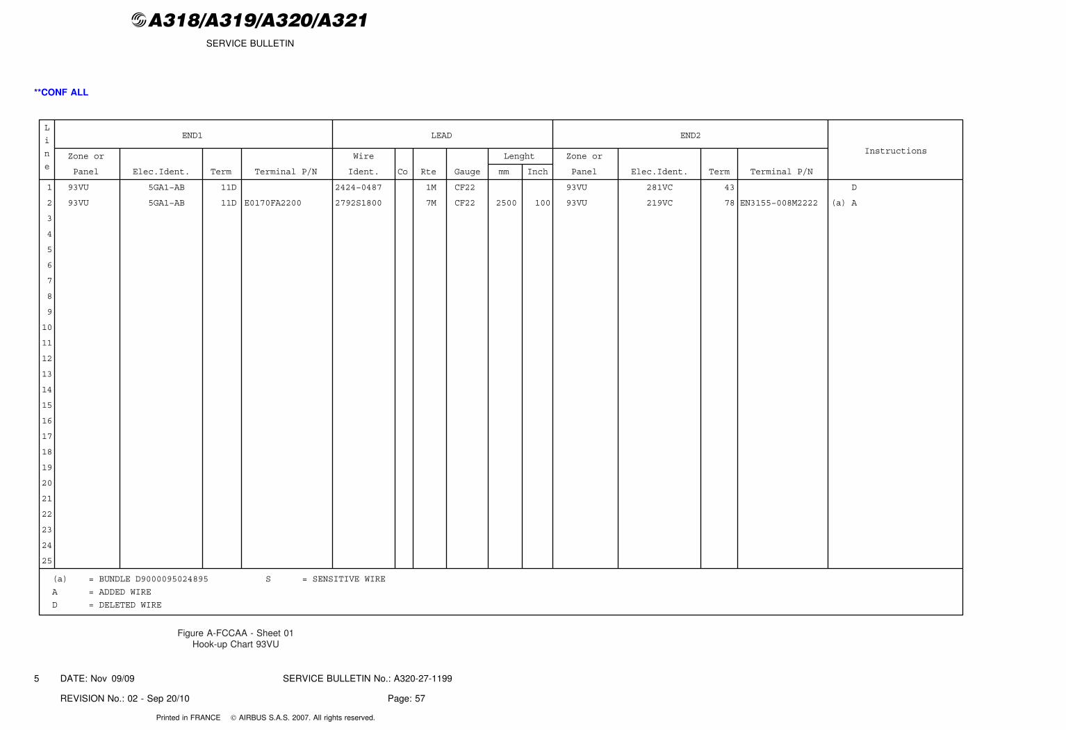
@A318/A319/A320/A321SERVICE BULLETIN
**CONF ALL
END1 LEAD END2
InstructionsZone or
Panel Elec.Ident. Term Terminal P/N
Wire
Ident. Co Rte Gauge
Lenght
mm Inch
Zone or
Panel Elec.Ident. Term Terminal P/N
L
i
n
e
1 93VU 5GA1−AB 11D 2424−0487 1M CF22 93VU 281VC 43 D
2 93VU 5GA1−AB 11D E0170FA2200 2792S1800 7M CF22 2500 100 93VU 219VC 78 EN3155−008M2222 (a) A
3
4
5
6
7
8
9
10
11
12
13
14
15
16
17
18
19
20
21
22
23
24
25
(a) = BUNDLE D9000095024895 S = SENSITIVE WIRE
A = ADDED WIRE
D = DELETED WIRE
Figure A-FCCAA - Sheet 01Hook-up Chart 93VU
DATE: Nov 09/09 SERVICE BULLETIN No.: A320-27-1199
REVISION No.: 02 - Sep 20/10 Page: 57
5
Printed in FRANCE © AIRBUS S.A.S. 2007. All rights reserved.
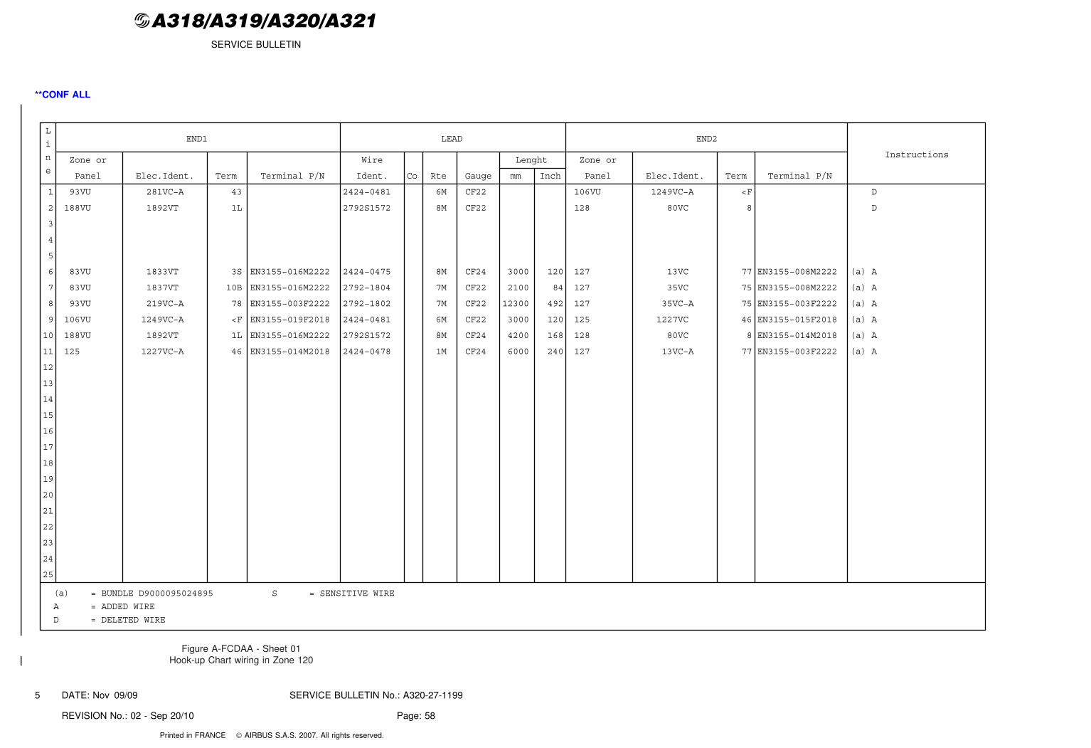
@A318/A319/A320/A321SERVICE BULLETIN
**CONF ALL
END1 LEAD END2
InstructionsZone or
Panel Elec.Ident. Term Terminal P/N
Wire
Ident. Co Rte Gauge
Lenght
mm Inch
Zone or
Panel Elec.Ident. Term Terminal P/N
L
i
n
e
1 93VU 281VC−A 43 2424−0481 6M CF22 106VU 1249VC−A <F D
2 188VU 1892VT 1L 2792S1572 8M CF22 128 80VC 8 D
3
4
5
6 83VU 1833VT 3S EN3155−016M2222 2424−0475 8M CF24 3000 120 127 13VC 77 EN3155−008M2222 (a) A
7 83VU 1837VT 10B EN3155−016M2222 2792−1804 7M CF22 2100 84 127 35VC 75 EN3155−008M2222 (a) A
8 93VU 219VC−A 78 EN3155−003F2222 2792−1802 7M CF22 12300 492 127 35VC−A 75 EN3155−003F2222 (a) A
9 106VU 1249VC−A <F EN3155−019F2018 2424−0481 6M CF22 3000 120 125 1227VC 46 EN3155−015F2018 (a) A
10 188VU 1892VT 1L EN3155−016M2222 2792S1572 8M CF24 4200 168 128 80VC 8 EN3155−014M2018 (a) A
11 125 1227VC−A 46 EN3155−014M2018 2424−0478 1M CF24 6000 240 127 13VC−A 77 EN3155−003F2222 (a) A
12
13
14
15
16
17
18
19
20
21
22
23
24
25
(a) = BUNDLE D9000095024895 S = SENSITIVE WIRE
A = ADDED WIRE
D = DELETED WIRE
Figure A-FCDAA - Sheet 01Hook-up Chart wiring in Zone 120
DATE: Nov 09/09 SERVICE BULLETIN No.: A320-27-1199
REVISION No.: 02 - Sep 20/10 Page: 58
5
Printed in FRANCE © AIRBUS S.A.S. 2007. All rights reserved.
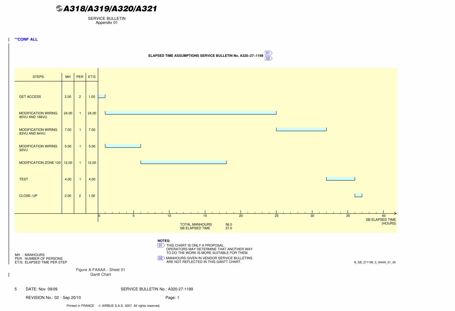
@A318/A319/A320/A321SERVICE BULLETIN
Appendix 01
**CONF ALL
ELAPSED TIME ASSUMPTIONS SERVICE BULLETIN No. A320−27−1199
SB ELAPSED TIME(HOURS)
GET ACCESS
MH ET/S
TOTAL MANHOURSSB ELAPSED TIME
56.037.0
STEPS
2.00 1.00
5 10 15 20 25 30 35 400
MODIFICATION WIRING 24.00 24.00
MODIFICATION WIRING 7.00 7.00
MODIFICATION WIRING 5.00 5.00
TEST 4.00 4.00
CLOSE−UP 2.00 1.00
MH
ET/S:PER
MANHOURS
ELAPSED TIME PER STEPNUMBER OF PERSONS
01
02
THIS CHART IS ONLY A PROPOSAL.OPERATORS MAY DETERMINE THAT ANOTHER WAYTO DO THE WORK IS MORE SUITABLE FOR THEM.
MANHOURS GIVEN IN VENDOR SERVICE BULLETINSARE NOT REFLECTED IN THIS GANTT CHART.
01
02
NOTES:
PER
2
1
1
1
1
2
MODIFICATION ZONE 120 12.00 12.001
::
N_SB_271199_5_AAAA_01_00
80VU AND 188VU
83VU AND 84VU
93VU
Figure A-FAAAA - Sheet 01Gantt Chart
DATE: Nov 09/09 SERVICE BULLETIN No.: A320-27-1199
REVISION No.: 02 - Sep 20/10 Page: 1
5
Printed in FRANCE © AIRBUS S.A.S. 2007. All rights reserved.
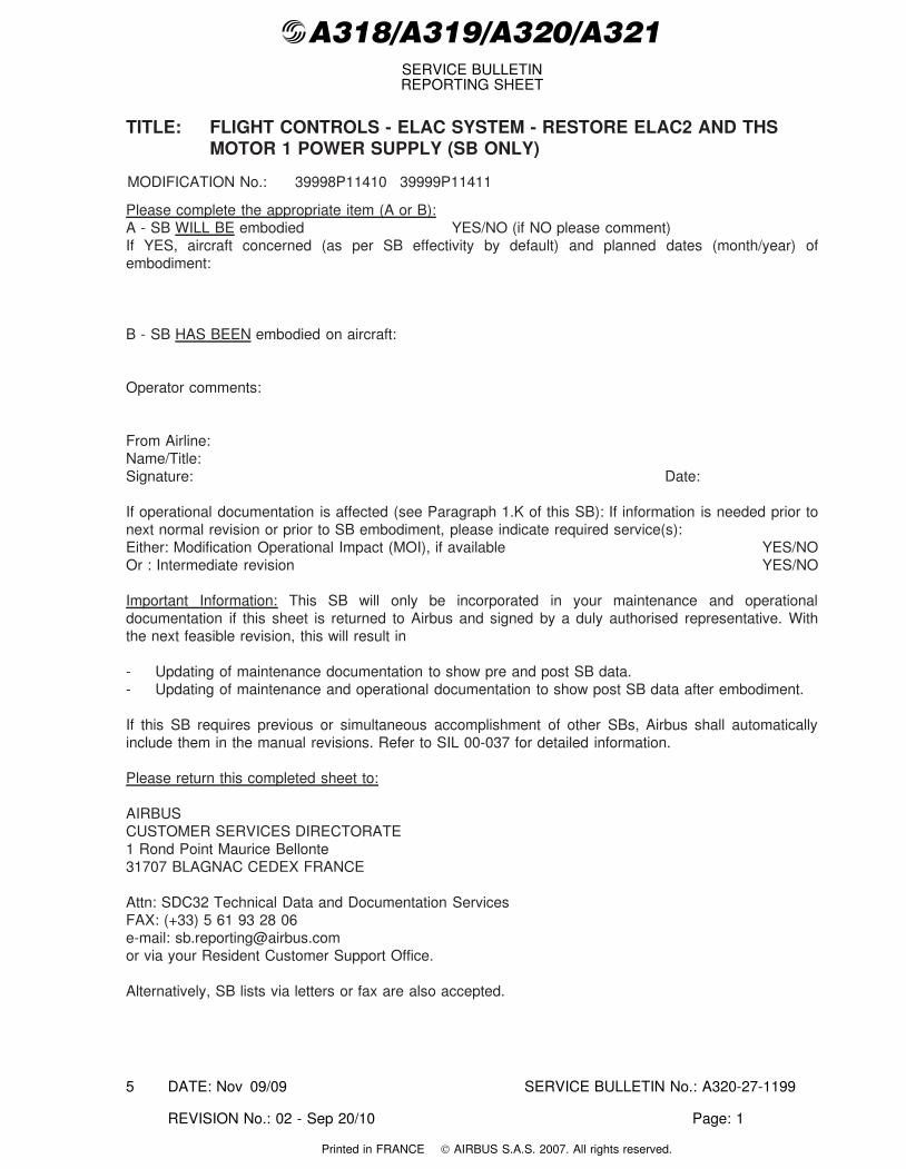
@A318/A319/A320/A321SERVICE BULLETINREPORTING SHEET
TITLE: FLIGHT CONTROLS - ELAC SYSTEM - RESTORE ELAC2 AND THSMOTOR 1 POWER SUPPLY (SB ONLY)
MODIFICATION No.: 39998P11410 39999P11411
Please complete the appropriate item (A or B):A - SB WILL BE embodied YES/NO (if NO please comment)If YES, aircraft concerned (as per SB effectivity by default) and planned dates (month/year) ofembodiment:
B - SB HAS BEEN embodied on aircraft:
Operator comments:
From Airline:Name/Title:Signature: Date:
If operational documentation is affected (see Paragraph 1.K of this SB): If information is needed prior tonext normal revision or prior to SB embodiment, please indicate required service(s):Either: Modification Operational Impact (MOI), if available YES/NOOr : Intermediate revision YES/NO
Important Information: This SB will only be incorporated in your maintenance and operationaldocumentation if this sheet is returned to Airbus and signed by a duly authorised representative. Withthe next feasible revision, this will result in
- Updating of maintenance documentation to show pre and post SB data.- Updating of maintenance and operational documentation to show post SB data after embodiment.
If this SB requires previous or simultaneous accomplishment of other SBs, Airbus shall automaticallyinclude them in the manual revisions. Refer to SIL 00-037 for detailed information.
Please return this completed sheet to:
AIRBUSCUSTOMER SERVICES DIRECTORATE1 Rond Point Maurice Bellonte31707 BLAGNAC CEDEX FRANCE
Attn: SDC32 Technical Data and Documentation ServicesFAX: (+33) 5 61 93 28 06e-mail: [email protected] via your Resident Customer Support Office.
Alternatively, SB lists via letters or fax are also accepted.
DATE: Nov 09/09 SERVICE BULLETIN No.: A320-27-1199
REVISION No.: 02 - Sep 20/10 Page: 1
5
Printed in FRANCE © AIRBUS S.A.S. 2007. All rights reserved.
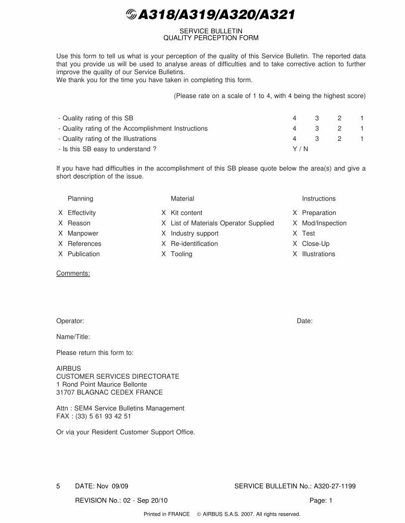
@A318/A319/A320/A321SERVICE BULLETIN
QUALITY PERCEPTION FORM
Use this form to tell us what is your perception of the quality of this Service Bulletin. The reported datathat you provide us will be used to analyse areas of difficulties and to take corrective action to furtherimprove the quality of our Service Bulletins.We thank you for the time you have taken in completing this form.
(Please rate on a scale of 1 to 4, with 4 being the highest score)
- Quality rating of this SB 4 3 2 1
- Quality rating of the Accomplishment Instructions 4 3 2 1
- Quality rating of the Illustrations 4 3 2 1
- Is this SB easy to understand ? Y / N
If you have had difficulties in the accomplishment of this SB please quote below the area(s) and give ashort description of the issue.
Planning Material Instructions
X Effectivity X Kit content X Preparation
X Reason X List of Materials Operator Supplied X Mod/Inspection
X Manpower X Industry support X Test
X References X Re-identification X Close-Up
X Publication X Tooling X Illustrations
Comments:
Operator: Date:
Name/Title:
Please return this form to:
AIRBUSCUSTOMER SERVICES DIRECTORATE1 Rond Point Maurice Bellonte31707 BLAGNAC CEDEX FRANCE
Attn : SEM4 Service Bulletins ManagementFAX : (33) 5 61 93 42 51
Or via your Resident Customer Support Office.
DATE: Nov 09/09 SERVICE BULLETIN No.: A320-27-1199
REVISION No.: 02 - Sep 20/10 Page: 1
5
Printed in FRANCE © AIRBUS S.A.S. 2007. All rights reserved.