Satellite Communications
57
Satellite Communication Col John Keesee
-
Upload
heritage336 -
Category
Documents
-
view
34 -
download
3
Transcript of Satellite Communications

Satellite Communication
Col John Keesee

Satellite Communications Architecture
• Identify Requirements• Specify Architectures• Determine Link Data Rates• Design & Size each link• Document your rationale

Definition
• Uplinks• Downlinks• Crosslinks• Relays• TT & C
Uplink Downlink
Intersatellitelinks
Relay satellite
Relay satellite
Relay satellite
Sensor satellite
Sensor satellite
Crossover orIntersatellitelinks
Mission data
Launchphase TT&C
TT&C
Satellite
Ground station
TT&C Tracking, Telemetry and Control
The communications architecture consists of satellites and ground stations interconnectedwith communications links. (Adapted from SMAD.)

Architectures:Defined by Satellite-Ground Geometry
• Store & Forward• Geostationary• Molniya• Geostationary/
Crosslink• LEO/ Crosslink
Adapted from SMAD.
Architectures:Defined by Function
• System Function– Tracking Telemetry & Command– Data Collection– Data Relay
• Satellite Design– Onboard Processing– Autonomous Satellite Control– Network Management

Communications Architecture: Selection Criteria
• Orbit• RF Spectrum• Data Rate• Duty Factor• Link Availability• Link Access Time• Threat
Advantages of Digital Communication
• Less distortion and interference • Easy to regenerate • Low error rates• Multiple streams can be easily multiplexed
into a single stream• Security• Drift free, miniature, low power hardware
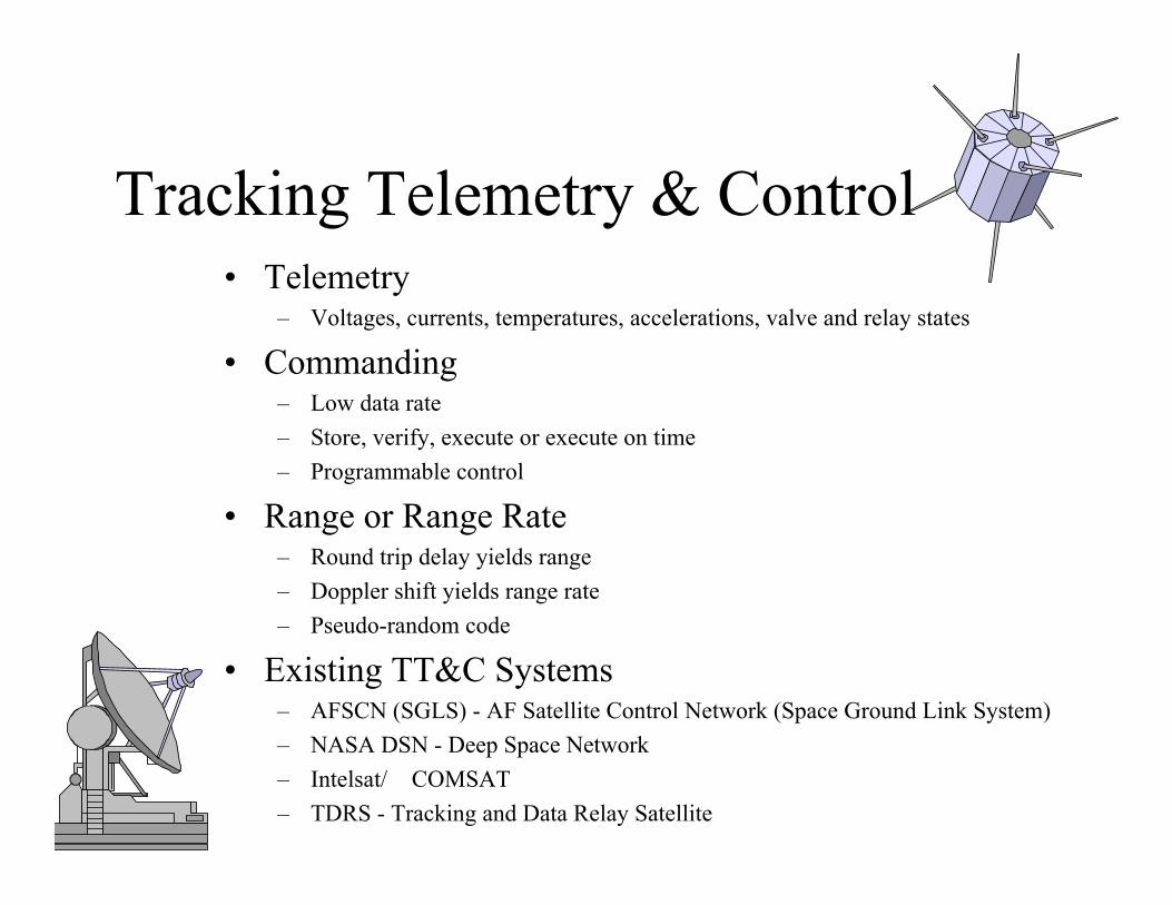
Tracking Telemetry & Control• Telemetry
– Voltages, currents, temperatures, accelerations, valve and relay states
• Commanding– Low data rate– Store, verify, execute or execute on time– Programmable control
• Range or Range Rate– Round trip delay yields range– Doppler shift yields range rate– Pseudo-random code
• Existing TT&C Systems– AFSCN (SGLS) - AF Satellite Control Network (Space Ground Link System)– NASA DSN - Deep Space Network– Intelsat/ �COMSAT– TDRS - Tracking and Data Relay Satellite

Data Collection Mission
cycledutySecondSamples
samplePixels
pixelBitsimagerDR
bYVn
XSwpushbroomDR
_/)(
)(
Adapted from SMAD.

Variable Definitions Chart 9
Variable Definition Units
DR Data Rate Bits/second
SW Swath Width Meters
X Across track pixel dimension
Meters
Vn Ground track velocity Meters/second
Y Along track pixeldimension
Meters
b Bits/pixel Bits
Reducing the Data Rate
• Increase the Duty Cycle• Collect only above-threshold data• Amplitude changes only• Data compression

Link Design Process
1. Define Requirements for each link2. Design Each Link
– Select frequency– Select modulation & coding– Apply antenna size & beam width constraints– Estimate atmospheric, rain attenuation– Estimate received noise, interference power– Calculate required antenna gain & transmitter power
3. Size the Payload– Payload antenna configuration, size & mass– Estimate transmitter mass & power– Estimate payload mass & power

Link Equation
Eb
No
P Ll Gt Ls La Gr
k Ts R
Energy/bit to noise-density ratio

Variable Definitions Chart 12
Variable Definition Units Units dBEb Energy per bit Watt-seconds dBNo Noise spectral
densityWatts/hertz dB
P Transmitter power
Watts dBW
Ll Line loss dB
Gt Transmitterantenna gain
db
Ls Space loss DB

Variable DefinitionsChart 12 continued
Variable Definition Units Units (dB)La Transmission
path lossdB
Gr Receiver gain dBk Boltzmann
constantJ/K dBW/(Hz-K)
Ts System noisetemperature
K
R Data rate Bits/second
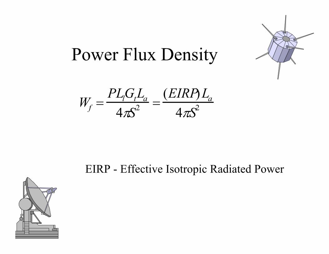
Power Flux Density
WfPLlGtLa
4 S2(EIRP)La
4 S2
EIRP - Effective Isotropic Radiated Power

Variable Definitionsfor Chart 16
Variable Definition Units Units (dB)Wf Power flux
densityW/m2
S Path length MEIRP Effective
IsentropicRadiatedPower
W DBW
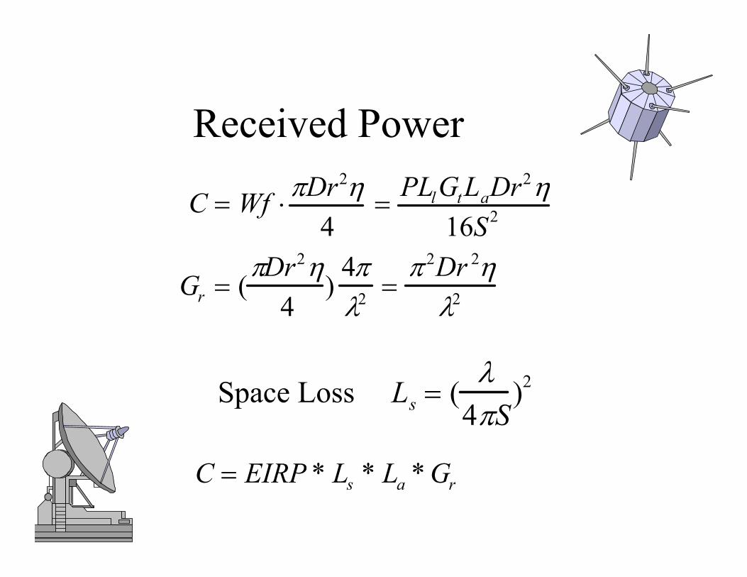
Received Power
C Wf Dr2
4PLlGtLaDr2
16S2
Gr (Dr2
4)
42
2Dr 2
2
Space Loss Ls (4 S
)2
C EIRP * Ls * La * Gr
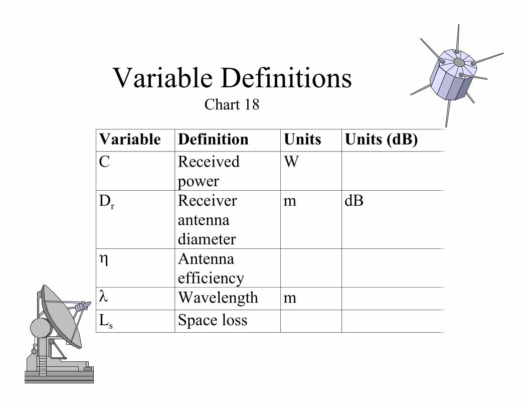
Variable DefinitionsChart 18
Variable Definition Units Units (dB)C Received
powerW
Dr Receiverantennadiameter
m dB
AntennaefficiencyWavelength m
Ls Space loss
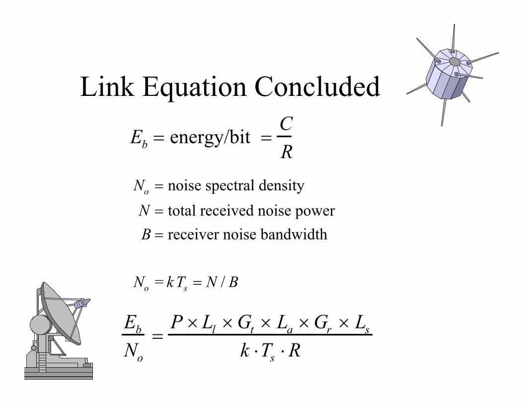
Link Equation ConcludedEb energy/bit
CR
No noise spectral densityN total received noise powerB receiver noise bandwidth
No = k Ts N / B
Eb
No
P Ll Gt La Gr Ls
k Ts R

Link Equation in dB
Eb
No
P Ll Gt Ls La Gr 228 .6 10 log Ts 10 log R
EIRP Ls La Gr 228 .6 10 log Ts 10 log R
CNo
EIRP Ls LaGr
Ts
228.6
CN
EIRP Ls LaGr
Ts
228.6 10log B
RIPEb
No
Gr
Ts
228.6 10log R (Received isentropic power)

Gain in dB
Gr
2 Dr2
2 fc
G 20log 20log D 20 log f 10log20log c (dB)
159.59 20log D 20log f 10log (dB)

Beamwidth
[degrees]f [GHz]D [m]
21f D
G 27,0002
L 12(e / )2 (dB)
Antenna gain
Offset beam loss
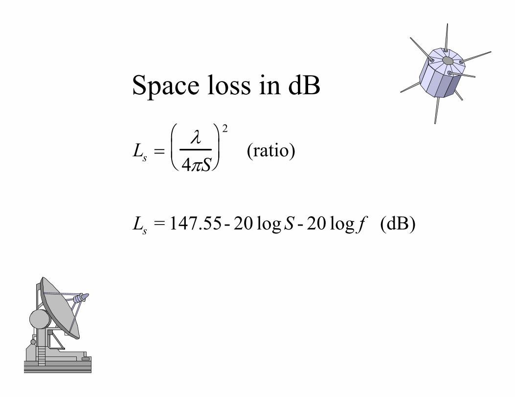
Space loss in dB
Ls 4 S
2
(ratio)
Ls = 147.55- 20 log S - 20 log f (dB)

System Noise Temperature- External to Antenna• Galactic noise• Clouds, rain in path• Solar noise (in mainbeam or sidelobe)• Earth (290K)• Man-made noise• Nearby objects• Satellite structure(See SMAD Fig 13-7)

System Noise Temperature- Internal to System
• Transmission lines and filtersF is a figure of merit for a receiver
Tr (1 L)T
L Po
Pi
• Low noise amplifierTr F 1 290K
Ts Tant To1 Lr
Lr
ToF 1
Lr

Variable DefinitionsChart 21
Variable Definition UnitsTr Receiver noise
temperatureK
L Power ratioT Component temperature KPo Output power WPI Input power WF Noise figureTo Reference temperature
(usually 290 K)K

Modulation
• Modulation modifies an RF Carrier signal so that it contains input signal information– Amplitude– Frequency– Phase– Polarization

Modulation Techniques
• BPSK - Binary Phase Shift Keying• QPSK - Quadriphased Phase Shift Keying• FSK - Frequency Shift Keying• MFSK - Multiple FSK• DPSK - Differential Shift Keying

Bit Error Rate
• Primary Figure of Merit for Digital Link Performance
• Energy/bit (Eb) must exceed the noise spectral density (No) to achieve a required BER

Coding
• Forward Error Correction sends additional data to help detect and correct errors.– Reduces the Eb/No requirement– Reduces required transmitter power– Reduces antenna size– Increases margin– Increases data rate and bandwidth
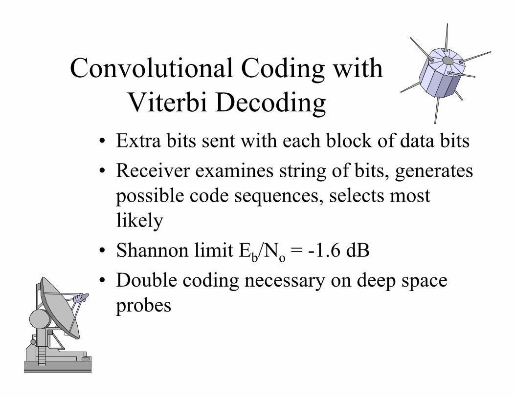
Convolutional Coding with Viterbi Decoding
• Extra bits sent with each block of data bits• Receiver examines string of bits, generates
possible code sequences, selects most likely
• Shannon limit Eb/No = -1.6 dB• Double coding necessary on deep space
probes
Attenuation
• Atmosphere absorbs some frequencies• Divide zenith attenuation by
sin(elevation angle)• Oxygen absorption at 60 GHz• Scintillation disrupts below 200 MHz
Rain and Cloud Attenuation
• Crane model for world’s climatic data• Important above 10 GHz• Worst for elevation angles < 20 degrees• Rain reduces availability

Rain and Cloud Attenuation
Adapted from SMAD.

Com’l.K
MILSTARUplink
ACTSUplink
DSCSDownlink500 MHz
GBSUplink
ACTSDownlink
Commercial SATCOM ServicesCommercial SATCOM Services
Government / Military SATCOM ServicesGovernment / Military SATCOM Services
VHF UHF L S X K V
VHF EHF
AF / FLTSATCOMUFO
MilitaryUHFBand
GovernmentS-Band (SGLS)
USGovernment
X-Band
1GHz 8GHz 18GHz 40GHz
75GHz
DSCSUplink
500 MHz
Military EHF (44/20)
inmarsat, odyssey,iridium, globalstar
odyssey,inmarsat,globalstar
INTELSAT,inmarsat INTELSAT
TELEDESIC,COMERCIAL,iridium,odyssey(gateway links)
SPACEWAY, CYBERSTAR, ASTROLINKTELEDESICiridium, odyssey (gateway links)
Com’l.L Com’l.
S
Com’l.C
Com’l.Ku
Com’l.Ka
3GHz
30GHz
UHF
C Ku
SHF
300MHz
SATCOM Frequencies UsageALL CAPS = Fixed Satellite Service (FSS)small case = Mobile Satellite Service (MSS)/Personal Comm Services (PCS)
1.61 1.622.4 2.5
4 6 12 14 17.3 20.2
225 Mhz 400 Mhz
1.761-1.842
2.200-2.290
7.25 7.75
7.9 8.4
7 8
19.2 20.2
29 30
20.2
MILSTAR,GBS
Downlink
21.2 30 31
43 45SATCOM users aresecondary in UHF:subject to interferencefrom terrestrial users Heavy orbital/terrestrial
congestion: much coordinationwith terrestrial users needed
1 GHz
1 GHz
1 GHz 1 GHz
2 GHz
27.5 30800 Mhz 900
“regular” cellular(Land Mobile Radio)
Freq at Risk: Int’l &US Commercialencroachment
GPSL2:
1227.6 MhzL1:
1575.42
12GHz
Ka

9090
010EAST WEST
LONGITUDELONGITUDE 20
30
40
50
60
70
80
10
20
30
40
50
60
70
80
10
20
30
40
50
60
70
80
100
110
120
130
140
150
160
170180
100
110
120
130
140
150
160
170
DEGREES DEGREES
0
0
10
20
30
40
50
60
70
80
NORTHERN HEMISPHERE
LEGEND
LOCATIONS OF CURRENT & PROPOSED GEOSTATIONARY SATELLITESWITH 17.3-GHz THRU 20.2-GHz DOWNLINKS
= SKYSAT (PROPOSED)PROPERTY OF:JOINT SPECTRUM CENTERREVISED 6-27-96
= SAMSAT (PROPOSED)
= EUROSKYWAY(PROPOSED)
= SOUTH AFRICASAT (PROPOSED)= ARTEMIS (PROPOSED)
= ASTROLINK (PROPOSED)= EDRSS (PROPOSED) = MORNINGSTAR (PROPOSED)
= ORION (PROPOSED)
= PANAMSAT (PROPOSED)
= SARIT (PROPOSED)
= INFOSAT (PROPOSED)
=HISPASAT (PROPOSED)
= GALAXY/SPACEWAY (PROPOSED)
= GE STAR (PROPOSED)
= MALTASAT (PROPOSED)
= KASTAR (PROPOSED)
= MILLENIUM (PROPOSED)
= INTELSAT-KA (PROPOSED)= RADIOSAT (PROPOSED)
= EASTSAT (PROPOSED)
(PROPOSED)= CANSAT
= DACOMSAT (PROPOSED)
= CYBERSTAR (PROPOSED)
= ECHOSTAR (PROPOSED)
= DIAMONDSAT (PROPOSED)
= USASAT (PROPOSED)
= TOR (OPERATIONAL/PROPOSED)
= USABSS (OPERATIONAL/PROPOSED)
= TONGASAT (PROPOSED)
= VISIONSTAR (PROPOSED)
= VOICESPAN (PROPOSED)
(PROPOSED)= VIDEOSAT= DFS (OPERATIONAL/PROPOSED)
= BSB (PROPOSED)
= EUTELSAT (OPERATIONAL/PROPOSED)
= AFRISAT (PROPOSED)
= LUX\KA (PROPOSED)
(PROPOSED)= USCSID
= ACTS (PROPOSED)
=ITALSAT (PROPOSED)
= N STAR (PROPOSED)
= PAKSAT (PROPOSED)
= MEGASAT (PROPOSED)
= SUPERBIRD (PROPOSED)
= DRTS (PROPOSED)
= ASIASAT (PROPOSED)
= CHINASAT (PROPOSED)
= ARABSAT (PROPOSED)
= KYPROS (PROPOSED)
= TURKSAT (PROPOSED)
=THIACOM (PROPOSED)
= YAMAL (PROPOSED)

Frequency Selection Drivers
• Spectrum availability and FCC allocation• Relay/Ground Station frequency• Antenna size• Atmospheric/Rain attenuation• Noise temperature• Modulation and coding

Communication Payload Antennas
• Parabolic• Helix• Horn• Phased Arrays
– Multiple beams– Hopping beams

Milstar Satellite Layout• Weight: 10,000 lb• Length: 51 ft (across payload)
116 ft (across solar arrays)• Array Power: 5,000 W• Orbit Altitude: 22,500 miles geosynchronous• Launch Vehicle: Titan IV/Centaur upper stage
Z+
+X
NSB #2
SHF
THRUSTERS
+X WINGPAYLOAD(LDR)
+X WING CROSSLINKANTENNASHF
AGILE
RCVUHF
EHFAGILE
WSB
XMTUHF
ECEHF
EC
NSB #1
SPACECRAFT BUS
REACTION WHEELASSEMBLIES (SCS)
HORIZONSENSORS
PROPELLANTTANKS
FLEXIBLE SUBSTRATESOLAR ARRAY PANELS
Z-
X-
THRUSTERS
-X WING CROSSLINKANTENNA
-X WING PAYLOAD
MDR NULLINGANTENNAS
CROSSLINKMDR DUCAANTENNAS
(MDR*, CROSSLINK)

UPLINK:5 AGILES, 2 NARROW SPOTS,1 WIDE SPOT, 1 EARTH COVERAGEDOWNLINK:SINGLE DOWNLINK TIME-SHARED BY:1 AGILE, 2 NARROW SPOTS,1 WIDE SPOT, 1 EARTH COVERAGE
UPLINK:2 NULLING SPOTS6 DISTRIBUTED USER COVERAGE
(DUCs)DOWNLINK:SINGLE DOWNLINK TIME-SHARED BY:2 SPOTS AND 6 DUCs
(Image removed due to copyright considerations.)
(Image removed due to copyright considerations.)
Multiple Access Strategies
• FDMA - Frequency Division Multiple Access
• TDMA - Time Division Multiple Access• CDMA - Code Division Multiple Access
– Phase Modulation plus pseudo-random noise
Antijam Techniques
• Spread Spectrum• Narrow beamwidths• On board processing• Nulling antennas

Special Topics
• Data security through encryption• Spatial, time and satellite diversity• Frequency hopping• Interleaving

Why Compress Data
• Need to send more data than bandwidth accommodates– Digital image files in particular are very large
• Bandwidth is limited by the link equation and international regulation
• Concept inseparable from data encoding

Early Development -- Huffmancodes
• Assign different number of bits to each possible symbol to minimize total number of bits– Example: Encode letters of alphabet– 26 symbols, each with equal chance of occurring => 5bits/symbol
(25 = 32 = lowest power of 2 above 26)– If R occurs 50% of time, use fewer bits to encode R.

Compression Algorithms
• Lossless compression– Ensures data recovered is exactly same as original data– Used for executable code, numeric data -- cannot tolerate
mistakes
• Lossy compression– Does not promise that data received is the same as data sent– Removes information that cannot later be restored– Used for still images, video, audio - Data contains more info than
human can perceive– Data may already contain errors/imperfections– Better compression ratios than Lossless (order of magnitude)
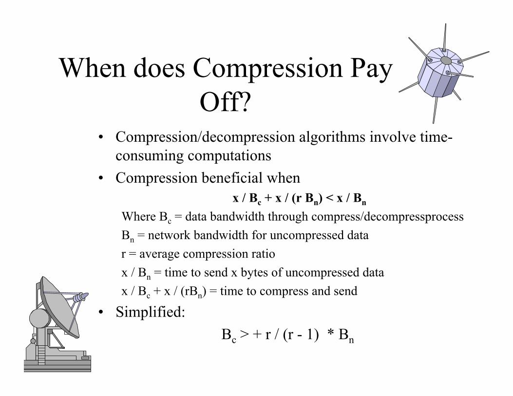
When does Compression Pay Off?
• Compression/decompression algorithms involve time-consuming computations
• Compression beneficial when x / Bc + x / (r Bn) < x / Bn
Where Bc = data bandwidth through compress/decompressprocessBn = network bandwidth for uncompressed datar = average compression ratiox / Bn = time to send x bytes of uncompressed datax / Bc + x / (rBn) = time to compress and send
• Simplified:Bc > + r / (r - 1) * Bn
Lossless Compression Algorithms
• Run Length Encoding• Differential Pulse Code Modulation -
DPCM• Dictionary-Based Methods
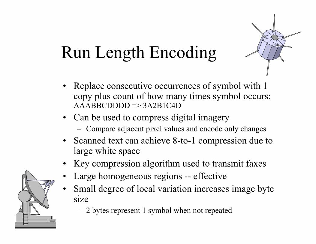
Run Length Encoding
• Replace consecutive occurrences of symbol with 1 copy plus count of how many times symbol occurs: AAABBCDDDD => 3A2B1C4D
• Can be used to compress digital imagery– Compare adjacent pixel values and encode only changes
• Scanned text can achieve 8-to-1 compression due to large white space
• Key compression algorithm used to transmit faxes• Large homogeneous regions -- effective• Small degree of local variation increases image byte
size– 2 bytes represent 1 symbol when not repeated

Differential Pulse Code Modulation - DPCM
• Represent differences between data – Output reference symbol– For each symbol in data, output difference between it and
reference symbol: AAABBCDDDD -> A0001123333
• When differences are small, encode with fewer bits (2 bits vs 8 bits)
• Takes advantage of fact that adjacent pixels are similar -1.5-to-1
• Delta encoding encodes symbol as difference from previous one: AAABBCDDDD -> A001011000.
• Works well when adjacent pixels are similar• Can combine delta encoding and RLE

Dictionary-Based Methods
• Lempel-Ziv (LZ) most well known, used by Unix compress command– Build dictionary of expected data strings– Replace strings with index to dictionary
• Example: "compression" (77-bits of 7-bit ASCII) has index 4978 (15 bits) in /usr/share/dict/words -- 5-to-1compression ratio
• How is the dictionary built?– A priori, static, tailored to data– Adaptively define based on contents of data. However,
dictionary must be sent with data for proper decompression

Graphical Interchange Format (GIF)
• Variation of LZ algorithm used for digital images– Reduce 24-bit color to 8-bit-color– Store colors in table which can be indexed by an 8-bit number– Value for each pixel replaced by appropriate index– Run LZ over result and create dictionary by identifying common
sequences of pixels
• If picture contains << 256 colors, can achieve 10-to-1 compression
• If picture contains > 256 colors, Lossy! (e.g., natural scenes)
Image Compression
• JPEG (Joint Photographic Experts Group) defines an algorithm and a format– Apply discrete cosine transform (DCT) to 8 x 8 block (transform
into spatial frequency domain). Lossless.– Low frequency = gross features; high frequency = detail– Quantize result, losing least significant info. Lossy– Encode result - RLE applied to coefficients. Lossless.

Color Images
• Three components used to represent each pixel - 3D– RGB - red, green, blue– YUV - luminance (Y) and two chrominance (U and V)
• To compress, each component is processed independently• Three components used to represent each pixel - 3D• JPEG can also compress multi-spectral images• Compress 24-bit color images by 30-to-1 ratio
– 24 bits -> 8 bits (GIF) gives 3-to-1– 3D JPEG compression gives 10-to-1

Video Compression
Moving Picture Experts Group (MPEG)Succession of still images displayed at video rate– Each frame compressed using DCT technique (JPEG) – Interframe redundancy
• Typically, can achieve 90-to-1 ratio; 150-to-1 possible• Involves expensive computation, typically done offline.

References
• Wertz, James R. and Wiley J.Larson, Space Mission Analysis and Design, Microcosm Press, El Segundo CA 1999, pg 533-586
• Morgan and Gordon, Communication Satellite Handbook, 1989
• Peterson and Davie, on reserve in Barker Library• http://www-isl.stanford.edu/people/gray/fundcom.pdf
![Satellite communications[1]](https://static.fdocuments.in/doc/165x107/588ae6481a28abab6c8b6391/satellite-communications1.jpg)