SAF Spectrum Comapct for Customers Mar2014 · PDF fileAttaching the flange Setting the...
54
Spectrum Compact Designed with field engineers in mind
Transcript of SAF Spectrum Comapct for Customers Mar2014 · PDF fileAttaching the flange Setting the...
Spectrum CompactDesigned with field engineers in mind

SAF Tehnika JSC
A designer, producer and distributor of digital
microwave data transmission equipment for
digital voice and data communication.
� Founded in 1999 with 15+ years of
experience in microwave field,
� Full-Cycle R&D and Production,
� Listed on NASDAQ OMX Riga since 2004,
� HQ & Manufacturing - Riga, Latvia (Europe),
� Quality assurance – ISO 2001, CE,
� Delivered over 100K radios.
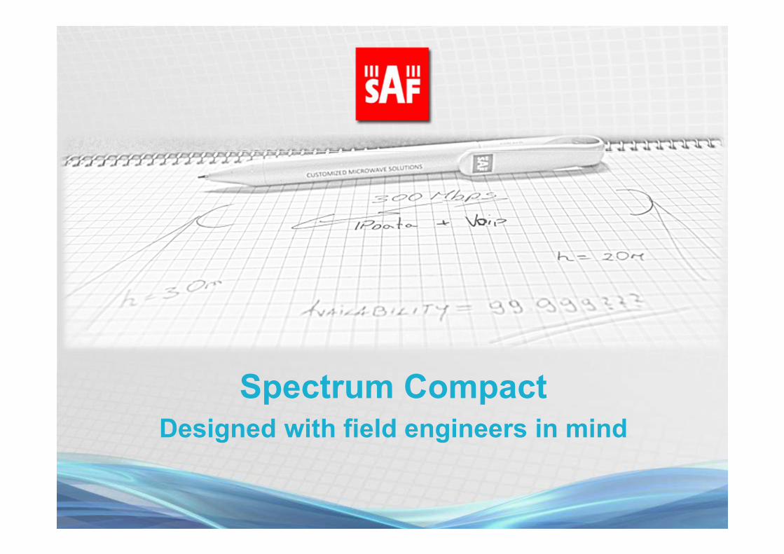
SAF worldwide presence
• Local offices
EUROPE HQ
DENVER, USA
BRISBANE AUSTRALIA
BOGOTA, COLOMBIA
GURGAON, INDIA
JAKARTA, INDONESIA
KUALA LUMPUR, MALAYSIALAGOS, NIGERIA
RIYADH, SAUDI
ARABIA
BRASIL

Regional sales FY 12/13

Remarkable achievements
149.2 km link over water
providing 8E1 throughput with
99,99% annual availability
Radio link transmitting data from 25km height
in Stratosphere to 149km ground station
Largest MW network in Lagos, Nigeria.
More than 200 SAF links deployed in area of approx. 25x32km

Spectrum Compact

Market of Spectrum Analyzers above 6 GHz
• Spectrum analyzers in higher than 6.x GHz frequencies
are produced by few companies.
• Products are mostly of 2 categories:
For Laboratory use
(30k – 100K USD)Portable; typically 5cm thick; 3-5kg
(20k – 30K USD)
Roots of the Spectrum Compact
• SAF is a MW Radio manufacturer with 15+ years
experience, thus having deep technical knowledge in
both – MW transmitter and receiver;
• Spectrum Compact was initially designed for
interference detection in markets with limited MW
Regulatory supervision;
• From our extensive experience in MW field, we knew
what functionality engineers needed in the field to
install, maintain and troubleshoot MW radio links;

SAF designed a
product, containing
only the most
essential and the
most frequently
required functionality
in the field.
We provide the
simplicity and ease of
use!
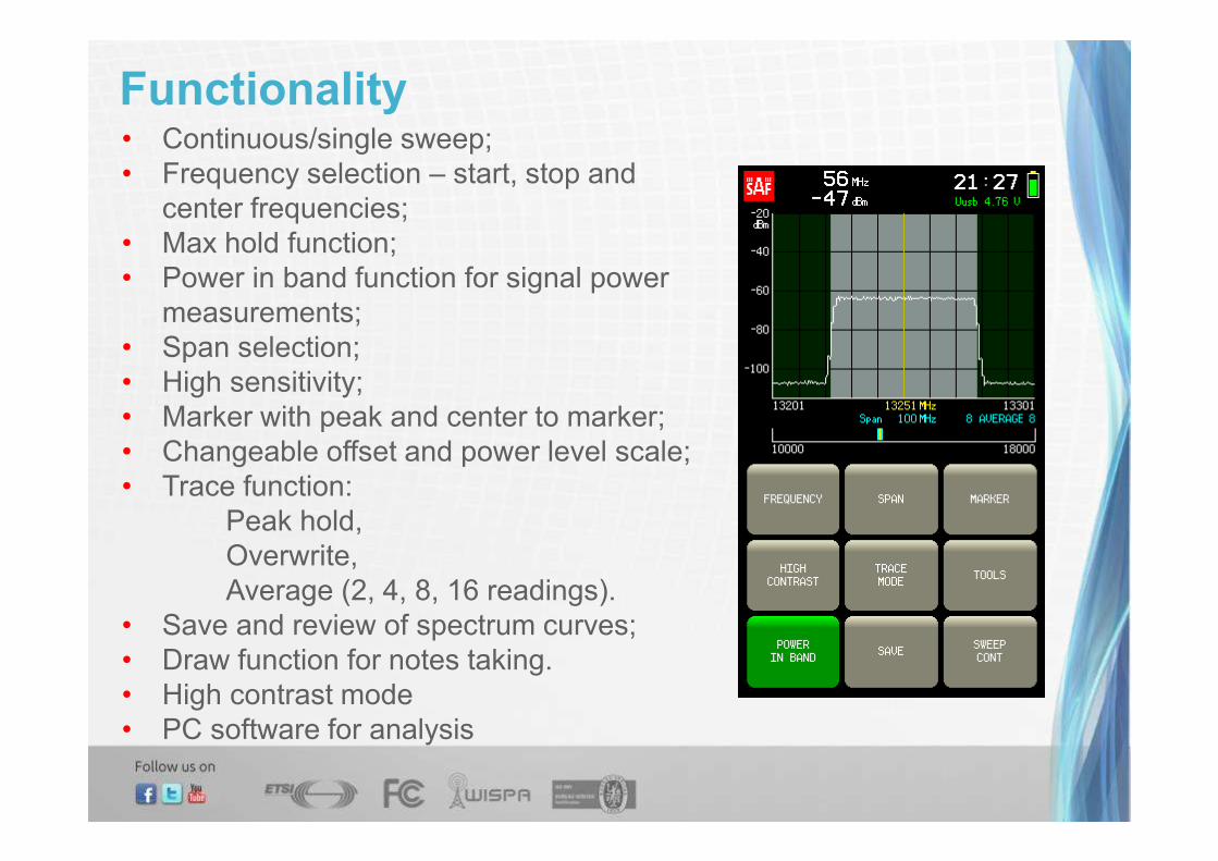
Functionality• Continuous/single sweep;
• Frequency selection – start, stop and
center frequencies;
• Max hold function;
• Power in band function for signal power
measurements;
• Span selection;
• High sensitivity;
• Marker with peak and center to marker;
• Changeable offset and power level scale;
• Trace function:
Peak hold,
Overwrite,
Average (2, 4, 8, 16 readings).
• Save and review of spectrum curves;
• Draw function for notes taking.
• High contrast mode
• PC software for analysis
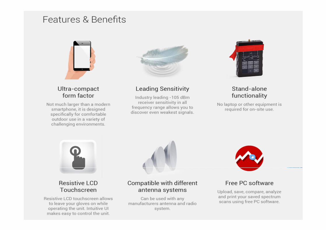

Spectrum Compact main features
• Set of 4 units, designed for ease of handling on the tower:
– 5.925 – 12.000 GHz
– 10.000 – 18.000 GHz
– 17.000 – 24.300 GHz
– 24.000 – 40.000 GHz
• Form factor:
– dimensions and weight of a unit:
(128 x 81 x 24 mm / 0,3 kg)
• Ease of use:
– intuitive GUI; instant ON/Off; built in DC blocker; USB
chargeable; resistive touchscreen,
– Specially designed for MW field engineers.
Units can be shared by
several teams.
Pay for what you use!

Spectrum Compact – typical on-site kit
Waveguide adapters to SMA
• Works as low gain antenna,
• Thumb screws for quick attachment to
antenna.
• Six different frequency range adapters
available.
Rugged RF cable
• SMA-SMA for frequencies from DC to
26,5 GHz or 2,92mm from DC to 50 GHz
• Excellent shielding effectiveness

Spectrum Compact Positioning
Spectrum Compact is a field spectrum analyzer –
a unique instrument designed for field
engineers.
The Spectrum Compact has the form factor of a
multi-meter and comes at only a fraction of a
portable Spectrum Analyzer's price.

Form factor of multi-meter,
functionality of
spectrum analyzer.
Multi-meter
Spectrum Compact
Hand-held Spectrum Analyzer
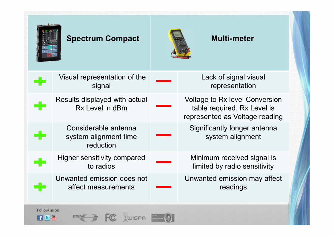
Spectrum Compact Multi-meter
Visual representation of the
signal
Lack of signal visual
representation
Results displayed with actual
Rx Level in dBm
Voltage to Rx level Conversion
table required. Rx Level is
represented as Voltage reading
Considerable antenna
system alignment time
reduction
Significantly longer antenna
system alignment
Higher sensitivity compared
to radios
Minimum received signal is
limited by radio sensitivity
Unwanted emission does not
affect measurements
Unwanted emission may affect
readings

Spectrum scan Adjacent channel interference Out-of-band interference
Co-channel interferenceIn-band interference Power in Band
Examples of the signal visual representation

High contrast mode Damaged transmitter 7 MHz channel
Reference Mask
Examples of the signal visual representation
Multipath Misconfigured Radio

Spectrum Compact vs Portable Spectrum Analyzers
Manufacturer Model Frequency RangeWeight
(kg)
Dimensions
(mm)
SAF Tehnika
Spectrum
Compact 5.9GHz – 40.0 GHz 0,3 x 4 128 x 81 x 24
Anritsu
Site Master
S820D 2 MHz - 20 GHz 2,3 254 x 178 x 61
Anritsu
Spectrum
Master 9 kHz – 43 GHz 3,8 315 x 211 x 77
Rhode & Schwarz HSF 20 9 kHz - 20 GHz 3,0 194 x 300 x 69
Tektronix SA2500 10 kHz - 6.2 GHz 5,5 230 x 330 x 120
Agilent Field Fox 5 kHz - 26.5 GHz 3,0 292 x 188 x 72
BK Precision 2658A 50 kHz - 8.5 GHz 1,8 162 x 70 x 260
Pendulum Path Align-R 1.8 GHz – 23.5GHz 3,2 89 x 213 x 333
Aaronia (Spectran) HF-60100 1 MHz – 9.4 GHz 0,430 250 x 86 x 27
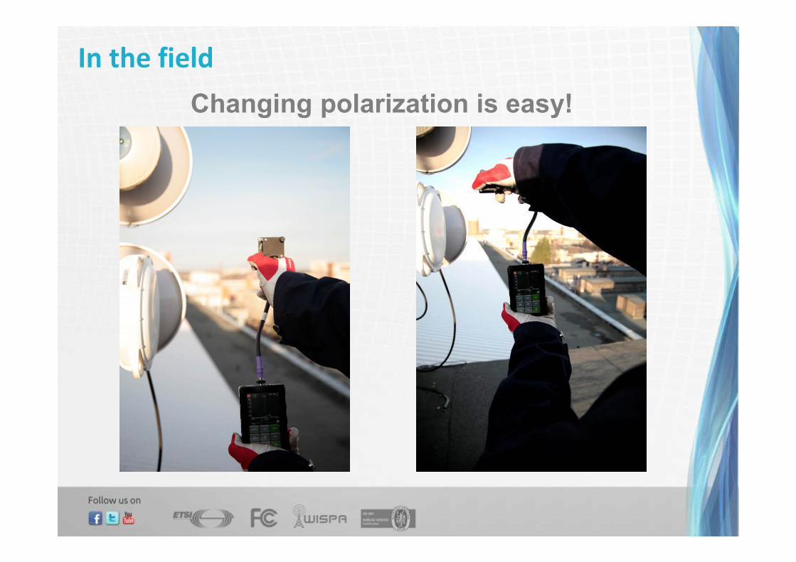
In the field
Changing polarization is easy!

In the field
Using hand-held
Horn antennas
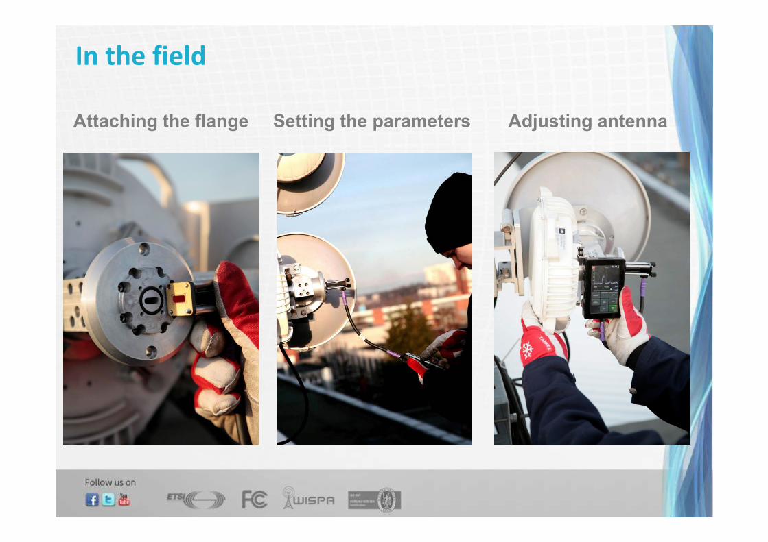
In the field
Attaching the flange Setting the parameters Adjusting antenna
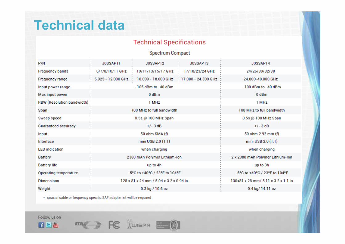
Technical data

Using Spectrum Compact readings
• In all stages of link life-cycle
Site survey,
Radio link installation,
Site acceptance,
Troubleshooting.
• Applications
Seeking for free channels,
Interference detection,
Verification of the radio configuration,
Antenna adjustment,
Cross-polarization adjustment,
Received signal power comparative measurements,
Investigation of the radio operation,
Investigation of the radio connection to the antenna,
Replacement of already installed antennas,
Saving the spectrum curves.
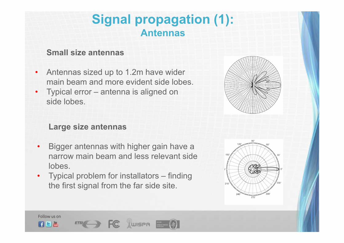
Signal propagation (1):Antennas
Small size antennas
• Antennas sized up to 1.2m have wider
main beam and more evident side lobes.
• Typical error – antenna is aligned on
side lobes.
Large size antennas
• Bigger antennas with higher gain have a
narrow main beam and less relevant side
lobes.
• Typical problem for installators – finding
the first signal from the far side site.
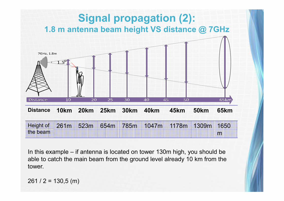
Distance 10km 20km 25km 30km 40km 45km 50km 65km
Height of
the beam261m 523m 654m 785m 1047m 1178m 1309m 1650
m
Signal propagation (2):1.8 m antenna beam height VS distance @ 7GHz
In this example – if antenna is located on tower 130m high, you should be
able to catch the main beam from the ground level already 10 km from the
tower.
261 / 2 = 130,5 (m)
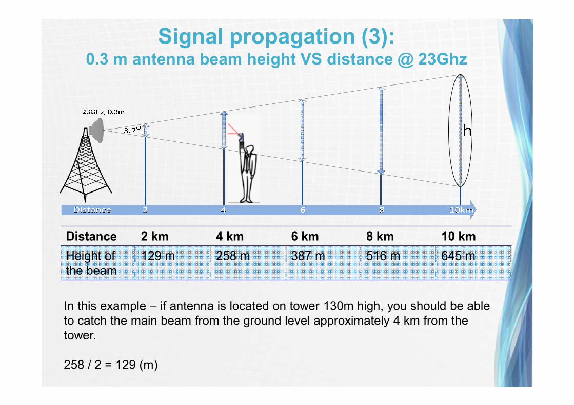
Distance 2 km 4 km 6 km 8 km 10 km
Height of
the beam
129 m 258 m 387 m 516 m 645 m
Signal propagation (3):0.3 m antenna beam height VS distance @ 23Ghz
In this example – if antenna is located on tower 130m high, you should be able
to catch the main beam from the ground level approximately 4 km from the
tower.
258 / 2 = 129 (m)
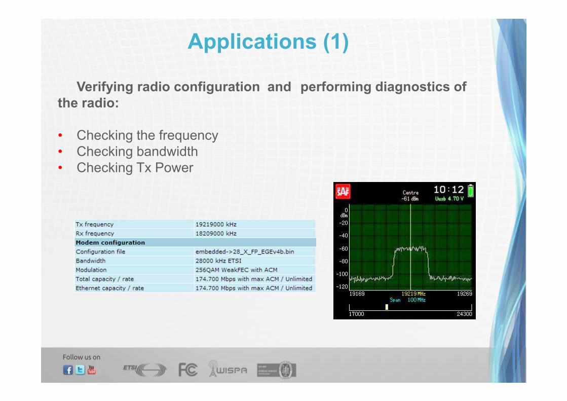
Applications (1)
Verifying radio configuration and performing diagnostics of
the radio:
• Checking the frequency
• Checking bandwidth
• Checking Tx Power

Case study (1)
Frequency readings from ground level
Phase: Troubleshooting Location: From the ground level
Problem:
The link did synchronize, but never worked in highest modulation. The Rx level
was according to calculations.
Description:
Installation was done by third party installers and client did not have direct
access to the site.
Solution:
Client did the frequency readings with
the Spectrum Compact, using Power
In Band function.
The received signal did not perfectly
match in the marked area, thus client
found that installers misconfigured one
of the radios by setting 5MHz off the
center of the channel.

Applications (2)
Seeking for free channels
• Useful in license-free bands e.g. 17GHz and 24Ghz radios
• Useful functionality in countries with weak or no spectrum
Regulatory supervision.
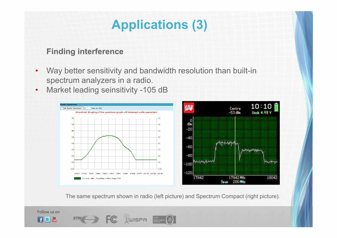
Applications (3)
Finding interference
• Way better sensitivity and bandwidth resolution than built-in
spectrum analyzers in a radio.
• Market leading seinsitivity -105 dB
The same spectrum shown in radio (left picture) and Spectrum Compact (right picture).
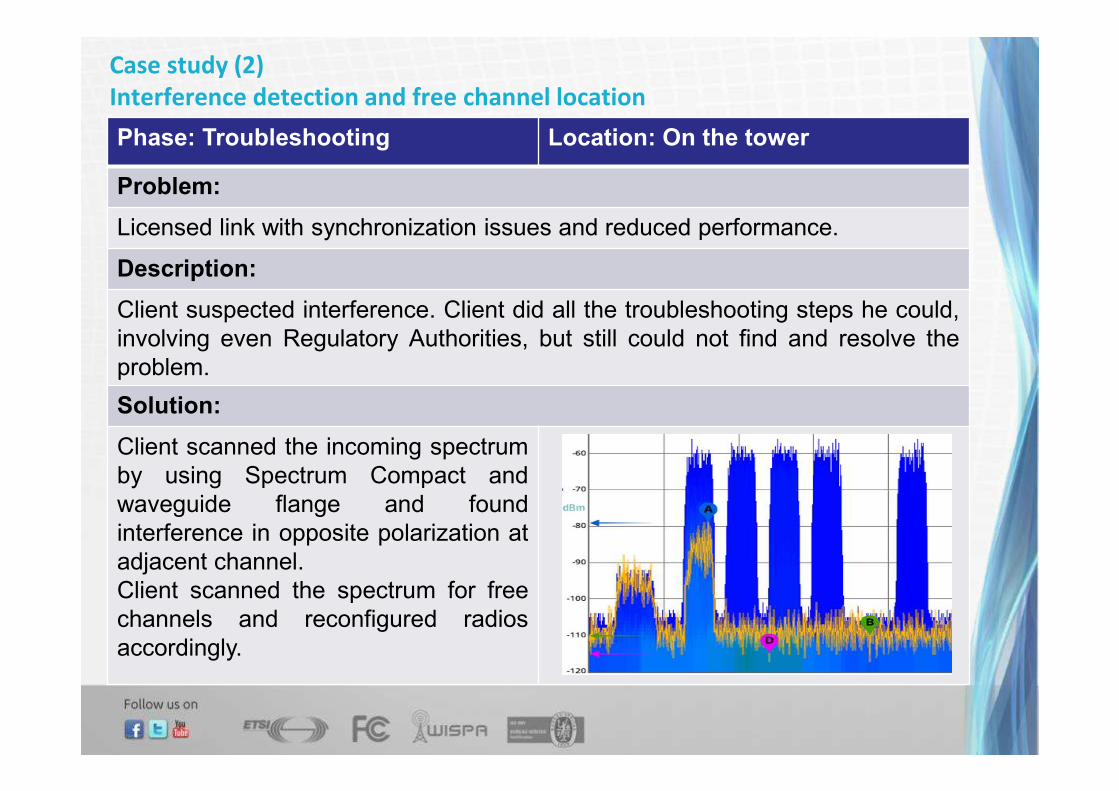
Case study (2)
Interference detection and free channel location
Phase: Troubleshooting Location: On the tower
Problem:
Licensed link with synchronization issues and reduced performance.
Description:
Client suspected interference. Client did all the troubleshooting steps he could,
involving even Regulatory Authorities, but still could not find and resolve the
problem.
Solution:
Client scanned the incoming spectrum
by using Spectrum Compact and
waveguide flange and found
interference in opposite polarization at
adjacent channel.
Client scanned the spectrum for free
channels and reconfigured radios
accordingly.
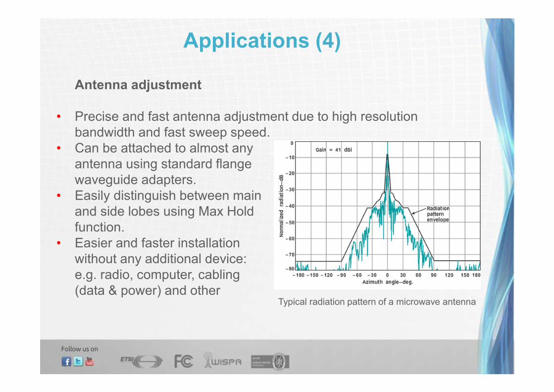
Applications (4)
Antenna adjustment
• Precise and fast antenna adjustment due to high resolution
bandwidth and fast sweep speed.
• Can be attached to almost any
antenna using standard flange
waveguide adapters.
• Easily distinguish between main
and side lobes using Max Hold
function.
• Easier and faster installation
without any additional device:
e.g. radio, computer, cabling
(data & power) and otherTypical radiation pattern of a microwave antenna

Case study (3)
Antenna alignment (1)
Phase: Installation Location: On the tower
Problem:
After 2.4m antenna installation, installers tried to align antenna for next 2 days.
Having no success, the new route for MW link was considered.
Description:
Installers during the alignment process could not find any incoming signal with
radio and RSSI readings.
Solution:
By attaching the Spectrum Compact to
the antenna and sweeping it, client
found incoming signal @ -100dBm
level.
After final alignment client reached the
desired signal level.

Case study (3)
Antenna alignment (2)
Phase: Troubleshooting Location: From the ground and On
the tower
Problem:
After installation link was 30dBm off the target.
Description:
Installer’s crew spent 3 days on the antenna alignment without any success.
Solution:
First, the near-end radio Tx signal quality was
checked from the ground level. Then on the
tower, by pointing waveguide flange to the
other side of the link, Spectrum Compact
received stronger Rx signal than in receiving
radio. That was an indication that antenna is
misaligned.
Using the Spectrum Compact, antenna
alignment was done in less than 10 minutes.

Applications (5)
Cross-polarization adjustment (Dual polarized Antenna adjustment)
• Dual polarized antenna installation requires precise angling to
achieve the best attenuation between vertical and horizontal signals.
In this case Spectrum Compact is very usefull.
• For correct XPIC functionality it is very important to align polarization
for antennas and ensure the highest cross-polarisation attenuation.
Radiation pattern for two polarizations
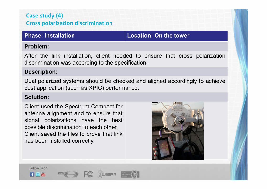
Case study (4)
Cross polarization discrimination
Phase: Installation Location: On the tower
Problem:
After the link installation, client needed to ensure that cross polarization
discrimination was according to the specification.
Description:
Dual polarized systems should be checked and aligned accordingly to achieve
best application (such as XPIC) performance.
Solution:
Client used the Spectrum Compact for
antenna alignment and to ensure that
signal polarizations have the best
possible discrimination to each other.
Client saved the files to prove that link
has been installed correctly.

Applications (6)
Received signal power comparative measurements
• Usable in Near LOS situations.
• Verify whether usable signal will be received at desired
antenna location
• Helps to determine potential installation positions on the tower
with the best received signal level

Applications (7)Replacement of already installed antennas
• Helps to replace old antenna with new one at short notice with
little link downtime
1. Install new antenna2. Do the alignment with SC unit
3. Hot swap radio to new antenna

Applications (8)
Investigation of the radio operation and radio connection to antenna
• Verify polarization of the signal
• Verify transmitted frequency
• Verify antenna and radio proper inteconnection
• Find out absolute radiated power level from antenna by using
values taken from Spectrum Compact and doing additional
calculations
Vertical Polarization Horizontal Polarization
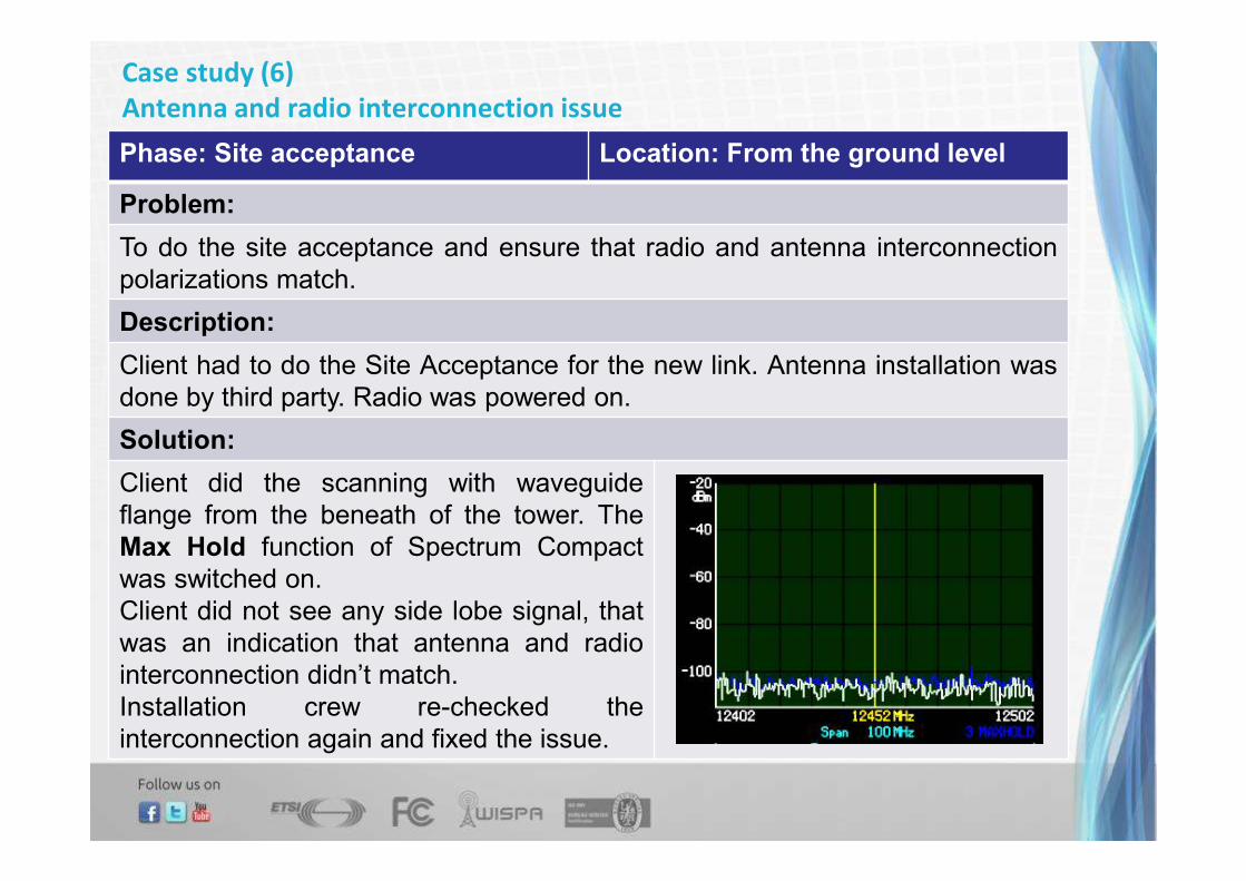
Case study (6)
Antenna and radio interconnection issue
Phase: Site acceptance Location: From the ground level
Problem:
To do the site acceptance and ensure that radio and antenna interconnection
polarizations match.
Description:
Client had to do the Site Acceptance for the new link. Antenna installation was
done by third party. Radio was powered on.
Solution:
Client did the scanning with waveguide
flange from the beneath of the tower. The
Max Hold function of Spectrum Compact
was switched on.
Client did not see any side lobe signal, that
was an indication that antenna and radio
interconnection didn’t match.
Installation crew re-checked the
interconnection again and fixed the issue.

Applications (9)Saving spectrum curves
• Save Spectrum curve for – analysis, installation report, later
comparison, troubleshooting.
• PC software – Spectrum Manager for advanced processing of
spectrum curves.
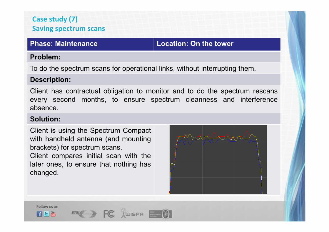
Case study (7)
Saving spectrum scans
Phase: Maintenance Location: On the tower
Problem:
To do the spectrum scans for operational links, without interrupting them.
Description:
Client has contractual obligation to monitor and to do the spectrum rescans
every second months, to ensure spectrum cleanness and interference
absence.
Solution:
Client is using the Spectrum Compact
with handheld antenna (and mounting
brackets) for spectrum scans.
Client compares initial scan with the
later ones, to ensure that nothing has
changed.
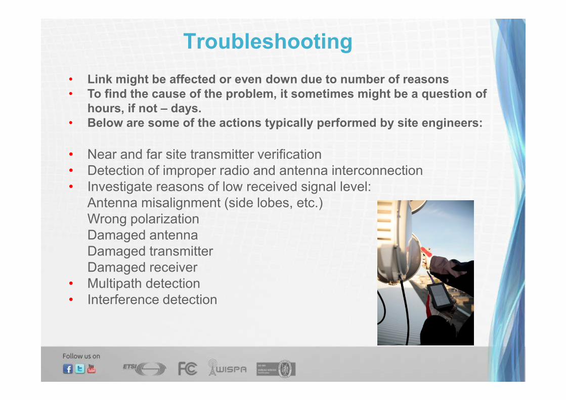
Troubleshooting
• Link might be affected or even down due to number of reasons
• To find the cause of the problem, it sometimes might be a question of
hours, if not – days.
• Below are some of the actions typically performed by site engineers:
• Near and far site transmitter verification
• Detection of improper radio and antenna interconnection
• Investigate reasons of low received signal level:
Antenna misalignment (side lobes, etc.)
Wrong polarization
Damaged antenna
Damaged transmitter
Damaged receiver
• Multipath detection
• Interference detection
Check Spectrum Compact on the Web
• Product homepage:http://saftehnika.com/en/spectrumanalyzer
• Official video:
http://www.youtube.com/watch?v=2GoNP974B4k
• In action:
https://www.youtube.com/channel/UCZu_pMdB
7wml7epWPrumPqQ

Accessories
Rugged RF cable, 30 cm
• SAM-SMA cable for frequencies from DC to 26,5 GHz
or 2,92 mm cable for frequencies from DC to 50 GHz.
• Excellent shielding effectiveness
Waveguide adapters to SMA
• Specially modified waveguide adapters with
thumb screws. No screwdriver is needed.
• Six adapters – each in different frequency range.

Accessories
USB charger
• Universal USB charger fitting different
types of AC sockets.
• 1.0 A Output.
• Good quality USB cables.
Lanyard
• Security lanyard for attaching the
unit to the hand or to the antenna

Accessories
Belt Bag
• Leather bag, for one Spectrum
Compact unit, SMA cable and
one waveguide adapter.
• Bag can be attached to the climbers belt.
Packaging
• Standard SAF cardboard packaging with an additional colorful
layer on the outside.

Additional accessories
Small antenna
• Small size portable antenna.
• Four frequency ranges:
06 – 10 GHz
11 – 15 GHz
17 – 24 GHz
26 – 40 GHz
Attenuators
• Coaxial attenuators for readings directly from
the radio.

Additional accessories
Protective case
• Watertight and shockproof case
with a soft padding inside.
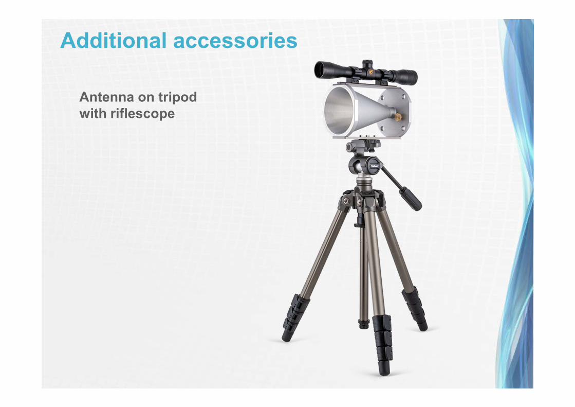
Additional accessories
Antenna on tripod
with riflescope
Additional accessories
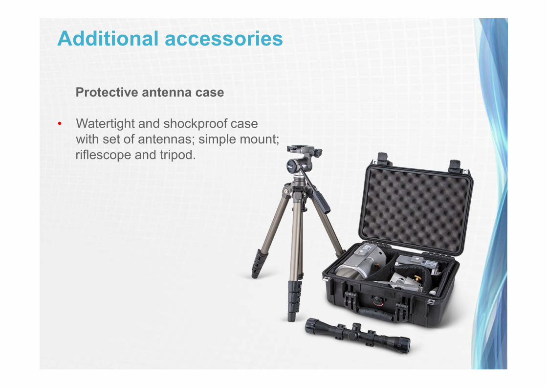
Protective antenna case
• Watertight and shockproof case
with set of antennas; simple mount;
riflescope and tripod.

Thank you!
SAF Tehnika JSC
24a, Ganibu dambis, Riga, Latvia
e-mail: [email protected]
www.saftehnika.com


![REBLE610-ODU XPIC ASI-IP-SDH linkDataSheets~REBLE-610-ODU_[EN].pdf · REBLE610-ODU XPIC ASI-IP-SDH link R2 2K15 The REBLE610-ODU is the split version of REBLE610 Elber full indoor](https://static.fdocuments.in/doc/165x107/5b3b58527f8b9a1a678e92aa/reble610-odu-xpic-asi-ip-sdh-datasheetsreble-610-oduenpdf-reble610-odu.jpg)