S E Dimensioning, N testing and application of metal oxide ... surge arrestor.pdf · testing and...
18
Dimensioning, testing and application of metal oxide surge arresters in railway facilities O V E R V O L T A G E P R O T E C T I O N
Transcript of S E Dimensioning, N testing and application of metal oxide ... surge arrestor.pdf · testing and...
Dimensioning,testing and application
of metal oxide surge arrestersin railway facilities
APPL
ICAT
ION
GUID
ELIN
ESO
V E
RVO
LTA
G E
P R
O T
E C
T I
O N
The overvoltage protection of the electrical energy supply installations ofrailway facilities holds increasing importance nowadays. This is not onlythe railways which are supplied with a. c. voltage but also increasingly bythe d. c. voltage railways.The standard-gauge railway is electrified with 3 kV d. c. voltage on over70 000 km rails (that means about 38 % of the total length of the rails ofthe electrical railways) and with 1,5 kV d. c. voltage on more than 20 000km (about 11%). That means that about half of the world-wide railwaylength of the long-distance traffic is operated with direct-current. The length of the electrified rails by the outer sub-urban service, including local trains, which operate with a d. c. voltage under 1000 V, is about 25 000 km. Thesefigures show the extent of the d. c. voltage systems by railways and also the importance of an optimal overvolta-ge protection which is adjusted to the specific demands of the d. c. voltage railways.
The application and dimensioning of metal oxide surge arresters (MO-surge arresters) in alternating current net-works with 50 Hz and 16 2/3 Hz of the railway supply is not very different from the one of the general energy sup-ply. On the other hand the dimensioning and the load of the MO-surge arresters in direct-current railway facilitieshave not been extensively dealt with until now. Moreover the modern MO-surge arresters without spark-gaps andwith silicon insulation make it possible to develop solutions for special applications.
Mr. Bernhard Richter, responsible for engineering and application of the overvoltage protective devices in the surgearrester division of ABB High Voltage Technologies Ltd, gladly presents in precise and clear form the technical basesof the MO-surge arresters and their application in railway facilities. Mr. Richter is an active member in differentworking groups of IEC SC 37 A and TC 81, and his activity field includes mainly the development, testing and theapplication of the surge arresters.
We hope, that you as a reader will find a lot of useful information in this booklet. We welcome amendments, sug-gestions and qualified hints, which may help us to cover all the demands of the customers.
ABB High Voltage Technologies Ltd
Wettingen, June 2000
First published: June 2000
All rights reserved.No part of this booklet may be reproduced or translated in any manner without the express written consent of ABB High Voltage Technologies Ltd.
© ABB High Voltage Technologies LtdDivision Surge Arresters, Wettingen / Switzerland
Foreword
1
2
Contents
1 Introduction
2 Surge arrester technology
2.1 MO-arresters and spark-gap arresters
2.2 Metal oxide resistors as arrester elements
3 Railway arresters of ABB
3.1 Construction of the arrester
3.2 Insulation made of silicone rubber
3.3 Technical data of the arresters
4 Operating conditions
4.1 Network short circuit power
4.2 Elevated ambient temperature
4.3 Mechanical stability
4.4 Pollution and cleaning
4.5 Flying sparks
4.6 Altitude adjustment for arrester housing
5 Tests
5.1 Definitions
5.2 Type tests
5.3 Routine- and acceptance tests
5.4 Special tests
6 Supply voltages of railway networks
6.1 Parameters of the most important voltage systems
6.2 Frequencies of the a. c. systems
6.3 Nominal voltages of d. c. railway systems
7 Overvoltage protection of the a. c. railway networks
7.1 Overvoltage protection of overhead lines and locomotives
8 Overvoltage protection of d. c. railway networks
8.1 Protection concept for d. c. tractive units
8.2 Dimensioning of the surge arresters
9 Conclusions
Bibliography
3
1 Introduction
Overvoltages in electrical supply networks result from the effects oflightning strokes and switching actions and therefore cannot beavoided. They endanger the electrical equipment, and due to econo-mical reasons, their insulation capability cannot be designed for allpossible cases. Therefore a more economical and safer on-line net-work calls for extensive protection of the electrical equipment againstunacceptable overvoltage loads. On principle this applies to all net-works of the energy supply.
We will not present here the different kinds of overvoltage and thepossibilities of reducing them. For general information you may usethe APPLICATION GUIDELINES: Dimensioning, testing and applicationof metal oxide surge arresters in medium voltage networks [1].
We want only to mention here that lightning strokes are the most dan-gerous threat for railway networks. That is why it is necessary toreduce the overvoltage to a safe value through appropriate protection.MO-surge arresters without spark-gaps give outstanding protection inthis situation.
2 Surge arrester technology
The so-called “conventional” surge arresters were almost exclusivelyinstalled in networks of the electrical energy supply up to the middleof the eighth decade of the last century. They consisted of an activepart (a series connection of SiC-resistors and plate spark-gaps)which was inserted in a porcelain housing.
In the last years there were two fundamental improvements in thesurge arrester technology. First, the series connection of SiC-resistorsand the plate spark-gaps were replaced by the metal oxid resistors(MO-resistors) [2] without plate spark-gaps, secondly the porcelainhousing was replaced by others made of polymer material, in case ofABB surge arresters the material is silicon.
2.1 MO-surge arresters and spark-gap arresters
A fundamental advantage of the MO-arresters is that, due to theirextremely non-linear characteristic of the MO-resistors, they do notneed any spark-gaps [3]. The current starts to flow through the arres-ter when the voltage is considerable lower than with spark-gap arres-ters, and therefore it is possible to limit the voltage much earlier. Thisaffords better protection and longer protection distance of the MO-arrester. Furthermore, an overvoltage by-pass cannot occur as withspark-gap arresters.
If the outside insulation of the arrester is very polluted, the potentialdistribution can shift along the active part, and this can cause unwan-ted spark-over in the spark-gap arresters, which in the end may des-troy the arrester. MO-arresters without spark-gaps have a fundamen-tally higher pollution resistance. This fact is especially important forhigher system voltages, because the longer an arrester is the moreimportant is a uniform potential distribution along the active part.
If more spark-gap arresters are connected in parallel usually only onearrester switches on during an overvoltage, thus reducing the over-voltage to a value below that of the sparking voltage of the otherparallel arresters. Therefore it is not possible to distribute the energyof the surge among more spark-gap arresters which are connected inparallel.
With MO-arresters without spark-gaps all the parallel MO-columnsconduct current at the same time, distributing the energy so that theenergy capacity as a limiting parameter disappears. The MO-arrestersdo not conduct any follow current like the spark-gap arresters, andtherefore they can be used both with 50 Hz and with 16 2/3 Hz. In thespark-gap arresters the follow current flows three times longer with16 2/3 Hz than with 50 Hz, which overloads the spark-gap arrester,(with constant voltage). In the past, spark-gap arresters, which wereused in networks of 16 2/3 Hz, had an inconvenient higher voltage thanthe arresters of 50 Hz, and implicitly a worse protection level.
This is the reason why MO-arresters can be used without any problemeven in direct current networks; because there is no necessity ofextinguishing a d. c. arc.
2.2 Metal oxide resistors as arrester elements
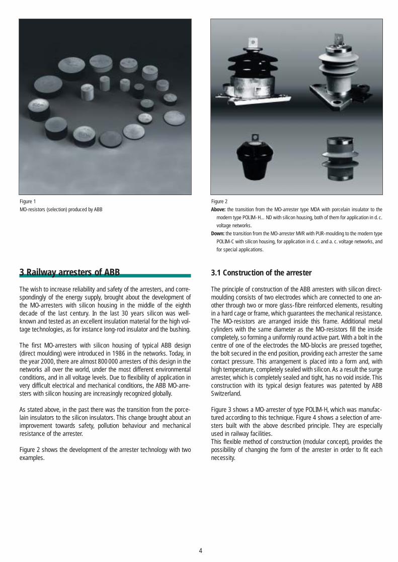
The MO-resistors make up the active part of the MO-arrester. TheMO-resistors are compressed and sintered in the form of roundblocks out of different metal oxides in powder form. The diameters ofthe MO-resistors of ABB High Voltage Technologies Ltd., made for allthe networks of the electrical energy supply and for special applica-tions, lie between 38 mm and 108 mm. The height of the blocks istypically between 1mm and 46 mm. The diameter of the MO-resistorsdecides the carrying capacity of the current, the height of theMO-resistors (or resistor stack) decides the voltage in continuousoperation, and the volume of the blocks the energy capacity.
The diameter of the MO-resistors correlate with the line dischargeclasses corresponding to IEC 60099-4, as shown in Table 1 [4]. As theIEC specification 60099-4 is only for a. c. systems higher than 3 kVrated, the tests and demands which are mentioned here, are for lowersystem voltages and especially for d. c. voltage networks only partlyapplicable. The standard IEC 61643-1 deals with surge protectivedevices (spd) for the electrical energy supply of a. c. voltage networksrated up to 1000 V and d. c. voltage networks rated up to 1500 V [5].Demands and testing for the overvoltage protection equipment forthe d. c. voltage applications are still under consideration.
Table 1
Correlation of the typical MO-resistors with the line discharge classes acc. to
IEC 60099-4.
The given energy relates to the operating duty test, and is the energy injected in the
arrester before the prove of the thermal stability of the arrester under applied con-
tinuous operating voltage.
The contact areas of the MO-resistors are metallized up to the edgeof the block with soft aluminium, the surface of the housing is withglass passivated, resulting in complete coverage of MO-material ofABB High Voltage Technologies MO-resistors. Figure 1 shows a selec-tion of MO-resistors.
Line discharge class 1 2 3 4 5acc. to IEC 60099-4
Diameter of MO-blocks in mm
38 / 42 47 62 75 96 / 108
Rectangular wave, 2 ms, in A 250 / 350 550 1000 1350 2000
Energy absorbtion in kJ / kVUc 3,6 / 3,5 5,5 9,0 13,3 19,8
4
3 Railway arresters of ABB
The wish to increase reliability and safety of the arresters, and corre-spondingly of the energy supply, brought about the development ofthe MO-arresters with silicon housing in the middle of the eighthdecade of the last century. In the last 30 years silicon was well-known and tested as an excellent insulation material for the high vol-tage technologies, as for instance long-rod insulator and the bushing.
The first MO-arresters with silicon housing of typical ABB design(direct moulding) were introduced in 1986 in the networks. Today, inthe year 2000, there are almost 800 000 arresters of this design in thenetworks all over the world, under the most different environmentalconditions, and in all voltage levels. Due to flexibility of application invery difficult electrical and mechanical conditions, the ABB MO-arre-sters with silicon housing are increasingly recognized globally.
As stated above, in the past there was the transition from the porce-lain insulators to the silicon insulators. This change brought about animprovement towards safety, pollution behaviour and mechanicalresistance of the arrester.
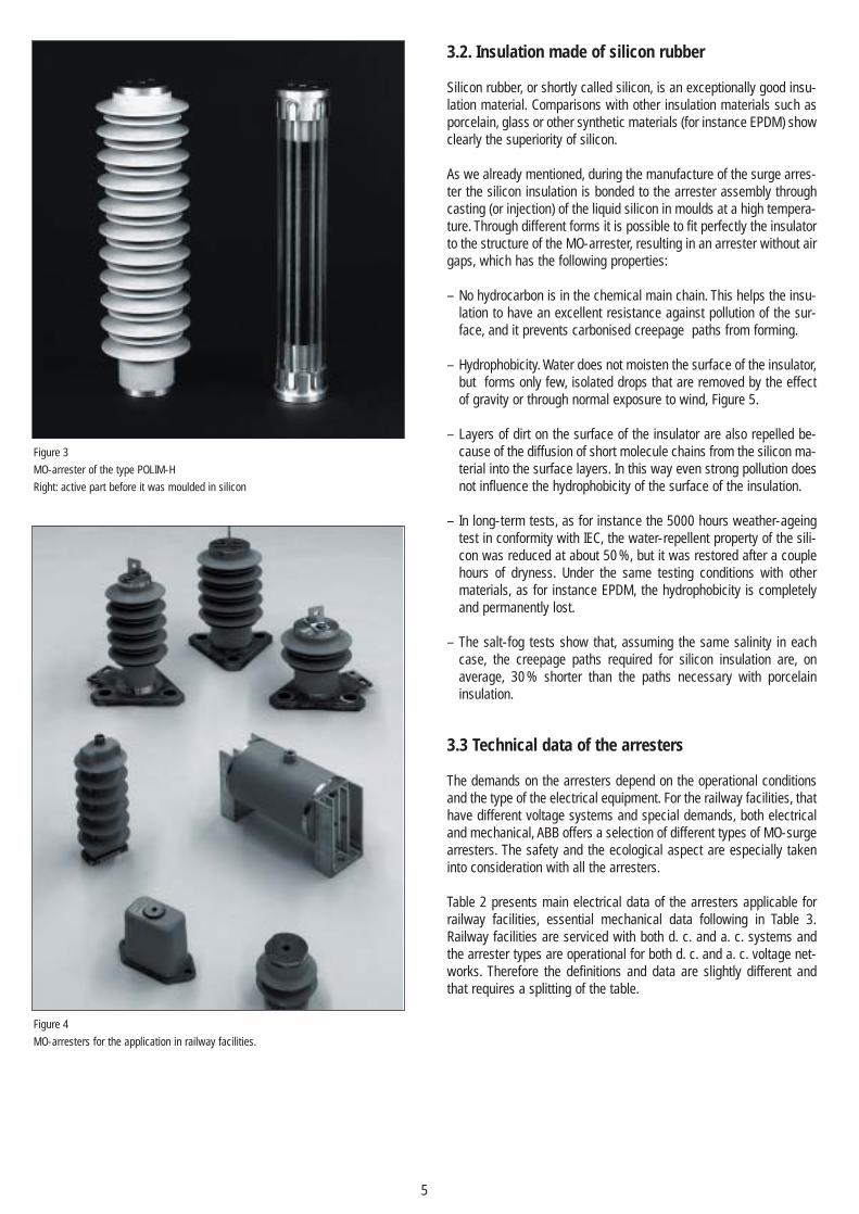
Figure 2 shows the development of the arrester technology with twoexamples.
3.1 Construction of the arrester
The principle of construction of the ABB arresters with silicon direct-moulding consists of two electrodes which are connected to one an-other through two or more glass-fibre reinforced elements, resultingin a hard cage or frame, which guarantees the mechanical resistance.The MO-resistors are arranged inside this frame. Additional metalcylinders with the same diameter as the MO-resistors fill the insidecompletely, so forming a uniformly round active part. With a bolt in thecentre of one of the electrodes the MO-blocks are pressed together,the bolt secured in the end position, providing each arrester the samecontact pressure. This arrangement is placed into a form and, withhigh temperature, completely sealed with silicon. As a result the surgearrester, which is completely sealed and tight, has no void inside. Thisconstruction with its typical design features was patented by ABBSwitzerland.
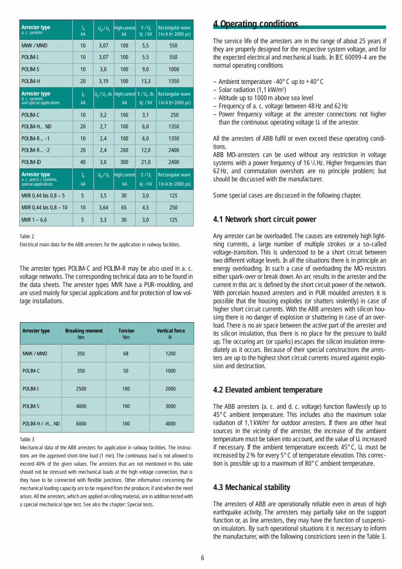
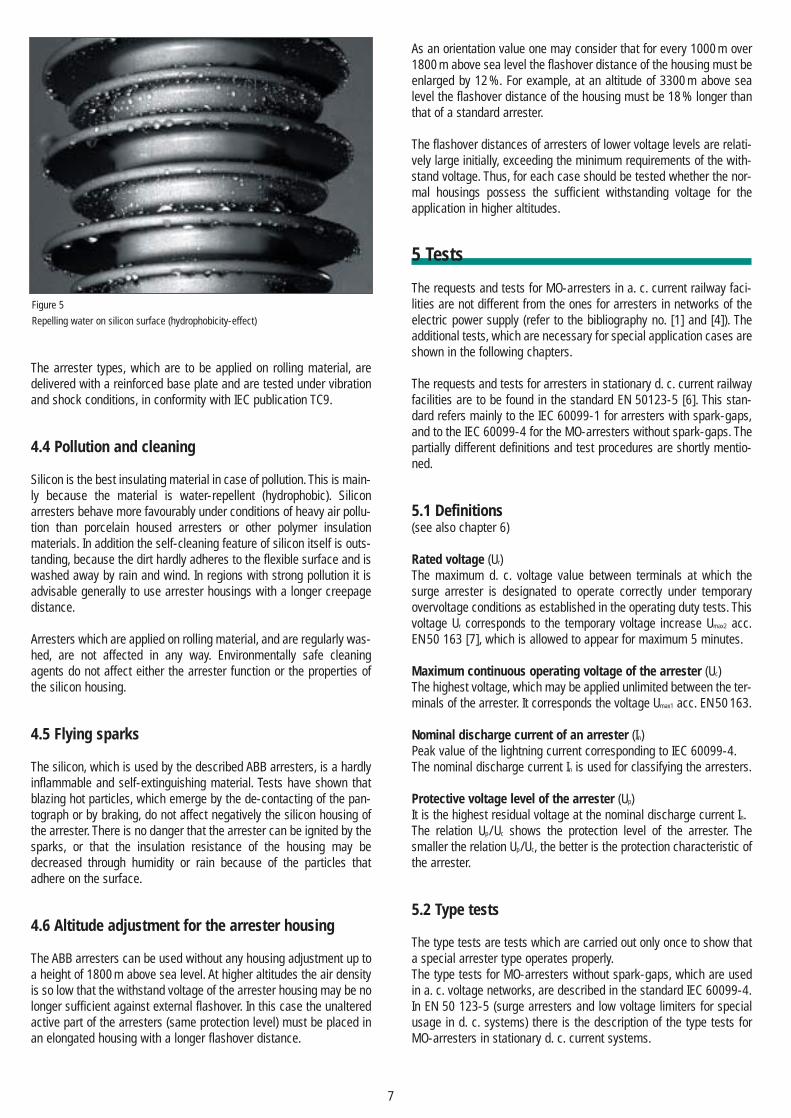
Figure 3 shows a MO-arrester of type POLIM-H, which was manufac-tured according to this technique. Figure 4 shows a selection of arre-sters built with the above described principle. They are especiallyused in railway facilities.This flexible method of construction (modular concept), provides thepossibility of changing the form of the arrester in order to fit eachnecessity.
Figure 1
MO-resistors (selection) produced by ABB
Figure 2
Above: the transition from the MO-arrester type MDA with porcelain insulator to the
modern type POLIM-H…ND with silicon housing, both of them for application in d. c.
voltage networks.
Down: the transition from the MO-arrester MVR with PUR-moulding to the modern type
POLIM-C with silicon housing, for application in d. c. and a. c. voltage networks, and
for special applications.
5
3.2. Insulation made of silicon rubber
Silicon rubber, or shortly called silicon, is an exceptionally good insu-lation material. Comparisons with other insulation materials such asporcelain, glass or other synthetic materials (for instance EPDM) showclearly the superiority of silicon.
As we already mentioned, during the manufacture of the surge arres-ter the silicon insulation is bonded to the arrester assembly throughcasting (or injection) of the liquid silicon in moulds at a high tempera-ture. Through different forms it is possible to fit perfectly the insulatorto the structure of the MO-arrester, resulting in an arrester without airgaps, which has the following properties:
– No hydrocarbon is in the chemical main chain. This helps the insu-lation to have an excellent resistance against pollution of the sur-face, and it prevents carbonised creepage paths from forming.
– Hydrophobicity. Water does not moisten the surface of the insulator,but forms only few, isolated drops that are removed by the effectof gravity or through normal exposure to wind, Figure 5.
– Layers of dirt on the surface of the insulator are also repelled be-cause of the diffusion of short molecule chains from the silicon ma-terial into the surface layers. In this way even strong pollution doesnot influence the hydrophobicity of the surface of the insulation.
– In long-term tests, as for instance the 5000 hours weather-ageingtest in conformity with IEC, the water-repellent property of the sili-con was reduced at about 50 %, but it was restored after a couplehours of dryness. Under the same testing conditions with othermaterials, as for instance EPDM, the hydrophobicity is completelyand permanently lost.
– The salt-fog tests show that, assuming the same salinity in eachcase, the creepage paths required for silicon insulation are, onaverage, 30 % shorter than the paths necessary with porcelaininsulation.
3.3 Technical data of the arresters
The demands on the arresters depend on the operational conditionsand the type of the electrical equipment. For the railway facilities, thathave different voltage systems and special demands, both electricaland mechanical, ABB offers a selection of different types of MO-surgearresters. The safety and the ecological aspect are especially takeninto consideration with all the arresters.
Table 2 presents main electrical data of the arresters applicable forrailway facilities, essential mechanical data following in Table 3.Railway facilities are serviced with both d. c. and a. c. systems andthe arrester types are operational for both d. c. and a. c. voltage net-works. Therefore the definitions and data are slightly different andthat requires a splitting of the table.
Figure 3
MO-arrester of the type POLIM-H
Right: active part before it was moulded in silicon
Figure 4
MO-arresters for the application in railway facilities.
6
4 Operating conditions
The service life of the arresters are in the range of about 25 years ifthey are properly designed for the respective system voltage, and forthe expected electrical and mechanical loads. In IEC 60099-4 are thenormal operating conditions
– Ambient temperature -40° C up to +40° C– Solar radiation (1,1 kW/m2)– Altitude up to 1000 m above sea level– Frequency of a. c. voltage between 48 Hz and 62 Hz– Power frequency voltage at the arrester connections not higher
than the continuous operating voltage Uc of the arrester.
All the arresters of ABB fulfil or even exceed these operating condi-tions.ABB MO-arresters can be used without any restriction in voltagesystems with a power frequency of 16 2/3 Hz. Higher frequencies than62 Hz, and commutation overshots are no principle problem; butshould be discussed with the manufacturer.
Some special cases are discussed in the following chapter.
4.1 Network short circuit power
Any arrester can be overloaded. The causes are extremely high light-ning currents, a large number of multiple strokes or a so-calledvoltage-transition. This is understood to be a short circuit betweentwo different voltage levels. In all the situations there is in principle anenergy overloading. In such a case of overloading the MO-resistorseither spark-over or break down. An arc results in the arrester and thecurrent in this arc is defined by the short circuit power of the network.With porcelain housed arresters and in PUR moulded arresters it ispossible that the housing explodes (or shatters violently) in case ofhigher short circuit currents. With the ABB arresters with silicon hou-sing there is no danger of explosion or shattering in case of an over-load. There is no air space between the active part of the arrester andits silicon insulation, thus there is no place for the pressure to buildup. The occuring arc (or sparks) escapes the silicon insulation imme-diately as it occurs. Because of their special constructions the arres-ters are up to the highest short circuit currents insured against explo-sion and destruction.
4.2 Elevated ambient temperature
The ABB arresters (a. c. and d. c. voltage) function flawlessly up to45° C ambient temperature. This includes also the maximum solarradiation of 1,1 kW/m2 for outdoor arresters. If there are other heatsources in the vicinity of the arrester, the increase of the ambienttemperature must be taken into account, and the value of Uc increasedif necessary. If the ambient temperature exceeds 45° C, Uc must beincreased by 2 % for every 5° C of temperature elevation. This correc-tion is possible up to a maximum of 80° C ambient temperature.
4.3 Mechanical stability
The arresters of ABB are operationally reliable even in areas of highearthquake activity. The arresters may partially take on the supportfunction or, as line arresters, they may have the function of suspensi-on insulators. By such operational situations it is necessary to informthe manufacturer, with the following constrictions seen in the Table 3.
Arrester typea. c. systems
MWK / MWD
POLIM-I
POLIM-S
POLIM-H
Arrester typed. c. systemsand special applications
POLIM-C
POLIM-H…ND
POLIM-R…-1
POLIM-R…-2
POLIM-ID
Arrester typea. c. and d. c systems,special applications
MVR 0,44 bis 0,8 – 5
MVR 0,44 bis 0,8 – 10
MVR 1 – 6,6
InkA
10
10
10
20
In
kA
10
20
10
20
40
In
kA
5
10
5
Up / Uc
3,07
3,07
3,0
3,19
Up / Uc, dc
3,2
2,7
2,4
2,4
3,0
Up / Uc
3,5
3,64
3,3
High current kA
100
100
100
100
kA
100
100
100
200
300
kA
30
65
High current
High current
30
E / UckJ / kV
5,5
5,5
9,0
13,3
E / Uc, dc
kJ / kV
3,1
6,0
6,0
12,0
21,0
E / Uc
kJ / kV
3,0
4,5
3,0
Rectangular waveI in A (t=2000 µs)
550
550
1000
1350
Rectangular wave
I in A (t=2000 µs)
250
1350
1350
2400
2400
Rectangular wave
I in A (t=2000 µs)
125
250
125
Arrester type Breaking moment Torsion Vertical forceNm Nm N
MWK / MWD 350 68 1200
POLIM-C 350 50 1000
POLIM-I 2500 100 2000
POLIM-S 4000 100 3000
POLIM-H / -H…ND 6000 100 4000
Table 2
Electrical main data for the ABB arresters for the application in railway facilities.
Table 3
Mechanical data of the ABB arresters for application in railway facilities. The instruc-
tions are the approved short-time load (1 min). The continuous load is not allowed to
exceed 40% of the given values. The arresters that are not mentioned in this table
should not be stressed with mechanical loads at the high voltage connection, that is
they have to be connected with flexible junctions. Other information concerning the
mechanical loading capacity are to be required from the producer, if and when the need
arises. All the arresters, which are applied on rolling material, are in addition tested with
a special mechanical type test. See also the chapter: Special tests.
The arrester types POLIM-C and POLIM-R may be also used in a. c.voltage networks. The corresponding technical data are to be found inthe data sheets. The arrester types MVR have a PUR-moulding, andare used mainly for special applications and for protection of low vol-tage installations.
7
The arrester types, which are to be applied on rolling material, aredelivered with a reinforced base plate and are tested under vibrationand shock conditions, in conformity with IEC publication TC9.
4.4 Pollution and cleaning
Silicon is the best insulating material in case of pollution. This is main-ly because the material is water-repellent (hydrophobic). Siliconarresters behave more favourably under conditions of heavy air pollu-tion than porcelain housed arresters or other polymer insulationmaterials. In addition the self-cleaning feature of silicon itself is outs-tanding, because the dirt hardly adheres to the flexible surface and iswashed away by rain and wind. In regions with strong pollution it isadvisable generally to use arrester housings with a longer creepagedistance.
Arresters which are applied on rolling material, and are regularly was-hed, are not affected in any way. Environmentally safe cleaningagents do not affect either the arrester function or the properties ofthe silicon housing.
4.5 Flying sparks
The silicon, which is used by the described ABB arresters, is a hardlyinflammable and self-extinguishing material. Tests have shown thatblazing hot particles, which emerge by the de-contacting of the pan-tograph or by braking, do not affect negatively the silicon housing ofthe arrester. There is no danger that the arrester can be ignited by thesparks, or that the insulation resistance of the housing may bedecreased through humidity or rain because of the particles thatadhere on the surface.
4.6 Altitude adjustment for the arrester housing
The ABB arresters can be used without any housing adjustment up toa height of 1800 m above sea level. At higher altitudes the air densityis so low that the withstand voltage of the arrester housing may be nolonger sufficient against external flashover. In this case the unalteredactive part of the arresters (same protection level) must be placed inan elongated housing with a longer flashover distance.
As an orientation value one may consider that for every 1000 m over1800 m above sea level the flashover distance of the housing must beenlarged by 12 %. For example, at an altitude of 3300 m above sealevel the flashover distance of the housing must be 18 % longer thanthat of a standard arrester.
The flashover distances of arresters of lower voltage levels are relati-vely large initially, exceeding the minimum requirements of the with-stand voltage. Thus, for each case should be tested whether the nor-mal housings possess the sufficient withstanding voltage for theapplication in higher altitudes.
5 Tests
The requests and tests for MO-arresters in a. c. current railway faci-lities are not different from the ones for arresters in networks of theelectric power supply (refer to the bibliography no. [1] and [4]). Theadditional tests, which are necessary for special application cases areshown in the following chapters.
The requests and tests for arresters in stationary d. c. current railwayfacilities are to be found in the standard EN 50123-5 [6]. This stan-dard refers mainly to the IEC 60099-1 for arresters with spark-gaps,and to the IEC 60099-4 for the MO-arresters without spark-gaps. Thepartially different definitions and test procedures are shortly mentio-ned.
5.1 Definitions(see also chapter 6)
Rated voltage (Ur)The maximum d. c. voltage value between terminals at which thesurge arrester is designated to operate correctly under temporaryovervoltage conditions as established in the operating duty tests. Thisvoltage Ur corresponds to the temporary voltage increase Umax2 acc.EN 50 163 [7], which is allowed to appear for maximum 5 minutes.
Maximum continuous operating voltage of the arrester (Uc)The highest voltage, which may be applied unlimited between the ter-minals of the arrester. It corresponds the voltage Umax1 acc. EN 50 163.
Nominal discharge current of an arrester (In)Peak value of the lightning current corresponding to IEC 60099-4.The nominal discharge current In is used for classifying the arresters.
Protective voltage level of the arrester (Up)It is the highest residual voltage at the nominal discharge current In.The relation Up/Uc shows the protection level of the arrester. The smaller the relation Up/Uc, the better is the protection characteristic ofthe arrester.
5.2 Type tests
The type tests are tests which are carried out only once to show thata special arrester type operates properly.The type tests for MO-arresters without spark-gaps, which are usedin a. c. voltage networks, are described in the standard IEC 60099-4.In EN 50 123-5 (surge arresters and low voltage limiters for specialusage in d. c. systems) there is the description of the type tests forMO-arresters in stationary d. c. current systems.
Figure 5
Repelling water on silicon surface (hydrophobicity-effect)
8
The following type tests are to be carried out:– testing of the insulation withstand voltage of the housing– testing of the residual voltage
with steep current impulsewith lightning current impulsewith switching current impulse
– testing with rectangular current waves– operating duty test – d. c. voltage versus time characteristic– tightness test – pressure relieve / overload test
The tests are similar to the ones for the MO-arresters, which are usedin alternating current networks. Only the procedure of the operatingduty test is different from the one of the MO-arresters in alternatingcurrent networks. This is why we describe here minutely only the ope-rating duty test and the ageing test for the MO-resistors applied ind. c. voltage systems.
Operating duty test – measuring of the residual voltage at In– conditioning (4 groups of 5 applications of In, superimposed on 1,2 Uc)– high current impulse 4/10 µs– heating up to 60° C (in oven)– high current impulse 4/10 µs– rated voltage Ur for 300 s– continuous voltage Uc for 1800 s– measuring of the residual voltage at In– visual inspection
In EN 50 123-5 is pointed out that in case there are not sufficientdirect current sources for this test, it is possible to carry out the testwith a. c. voltage, by arrangement between the manufacturer and thecustomer. The described procedure of the operating duty test is theone for high current impulse test. The operating duty test with swit-ching surge current is still under consideration.
The experience shows that, corresponding to IEC 60099-4, the MO-arresters tested with a. c. voltage, which have the requested dimen-sioning, can be used without any problems in d. c. voltage networks,because the demands and the testing procedure are almost similar.
Accelerated ageing testThis test has to show that the power losses of the arrester in the net-work under applied continuous operating voltage does not increasewith time. In order to demonstrate this, the power losses are mea-sured in a time accelerated ageing test under increased load. It isdecisively important that this test should be carried out with d. c.voltage. It is known that MO-material, which has a long-time stabilitywith the alternating voltage load, is not necessarily long-time stablewith direct voltage load. The ageing tests which are carried out witha. c. voltage are not transferable to the application in d. c. voltage networks.
All ABB MO-resistors, which are installed in arresters for d. c. voltagenetworks, fulfil the most strict demands towards the long-time sta-bility under d. c. voltage load.
5.3 Routine- and acceptance tests
The routine tests are carried out corresponding to IEC 60099-4, andthey are not different to the tests for arresters which are used in a. c.voltage networks of the general electrical energy supply.Acceptance tests are in principle to be agreed upon by the manufac-turer and the customer.
5.4 Special tests
The existing standards, which were mentioned earlier, are valid for thearresters with porcelain housing and are therefore only partially appli-cable for modern construction with polymer housing. Working grouppaper IEC TC 37/199/CDV discusses tests for MO-arresters with poly-mer housing. The demands and procedure for tightness, pollution andoverload tests are still under consideration in the relevant workinggroups of IEC. Therefore special tests were carried out by ABBSwitzerland in order to prove the behaviour of the MO-arrester withsilicon housing under extreme conditions.
Weather-ageing testPollution and ageing tests under extreme weather conditions, whichare carried out on complete arresters, with partially cyclical load andtest duration between 1000 h and 5000 h, give realistic informationabout the behaviour of the arrester in the network. In the IEC workinggroup paper TC 37/199/CDV [8] two procedures are recommended.Procedure A is a test lasting 1000 h with constant salt fog from 1 to10 kg/m3 salt content under applied continuous operating voltage Uc.Procedure B is a test lasting 5000 h in all with changing stress of UVrays (solar radiation), rain, dry heat, steam and salt fog under appliedcontinuous operating voltage Uc.
Figure 6 shows the cyclical stress during the test.The ABB arresters with silicon housing have easily passed the verydemanding test of procedure B.
Figure 6
The cycle of the weather-ageing test after procedure B corresponding TC 37/199/CDV.
Humidity
0 2 4 6 8 10 12 14 16 18 20 22 24
Heat
Rain
Salt fog 7kg / m3
Solar-radiation
not active
Hours
active
Voltage Uc
Test with high air humidityThis long-time test was carried out at the Technical University ofTampere in Finland as a research project. The test time was longerthan two years. During all this time the tested arresters were in a cli-matic chamber under a temperature of 30° C up to 35° C, a relativeair humidity of 95 % up to 100 %, and with a. c. voltage applied.Additional, each month the arresters were set under rain. During thewhole time of the test no changes appeared in the electrical charac-teristics and no signs of possible penetration of humidity were detec-ted. The MO-arresters with the described silicon direct moulding aretight even under such extreme environmental conditions. As a com-parison, tests were done with other constructions and they showedthat only the arresters with the silicon direct moulding were capableto withstand such stresses. Especially the arresters that, due to theconstruction, have inclusions of air could not withstand this extremehumidity stress. The results of the tests are published in [9] and [10].
Deep temperature testIn order to test the behaviour of the arresters at extreme deep tempe-ratures a deep temperature test was carried out. The MO-arresterswith silicon housing were cooled down to - 60° C under applied a. c.voltage in a climatic chamber. The cycle of the test in the climaticchamber is seen in Figure 7. The electrical characteristics of thearrester were measured before and after the temperature test in thechamber. No changes were noticed. The mechanical behaviour of thesilicon, as well as the chemical bond of the different materials amongone another were of special interest during this temperature testunder extreme conditions. The silicon maintains its flexibility even inthese deep temperatures, and no chemical or mechanical changeswere observed.
In an additional experiment, MO-arresters with silicon housing weresubmerged in water and tested with a temperature cycle between+ 60° C and - 40° C. Figure 8 shows the test cycle. Even repeatedfreezing and heating (up to 60° C in water) of the arrester did notinfluence either the electrical or the mechanical behaviour of thearrester.
On the basis of these very positive results it is possible to guaranteethe employment of ABB direct moulding MO-arresters without anyproblems up to - 60° C.
UV radiation testIn regions with a strong solar radiation it is important to know thebehaviour of polymer materials under UV radiation stress. The ener-gy of the radiation can crack the surface of the insulator made of asynthetic material, and as a result the insulator may erode and final-ly fail. The silicon behaves very positively under such conditions; thiswas tested during long-time tests in out-of-door test-fields, as forinstance in Tunisia and South Africa. In addition, tests with UV radia-tion stress were carried out in the lab, for more than 1000 hourscorrespondingly to the relevant standards.
UV radiation represents no problem for the silicon, quite the opposite,the UV radiation has a supporting influence by the restoration of thehydrophobicity of the surface of the silicon following a long period ofpollution.
Sparking Through the jumping of the pantographs and during braking it is pos-sible that hot rubbed-off particles may arise; they may be sprayed onthe silicon insulation of the arrester which is close by (overhead lineor the locomotive). In order to test whether such a sparking may havea negative influence on the silicon insulation, the arrester was expo-sed to an enforced sparking stress. The surface of the arrester wassprayed with sparks from different distances and for various periodsof time, with the help of a grinding wheel and iron rails. After that thewithstand voltage of the insulation was measured under rain. The testresults showed no change in the insulating behaviour. There were noburning prints to be found on the surface of the silicon. Because sili-con is a material which is very difficult to ignite and is also self-extin-guishing, there is no danger that the arrester with silicon housingcould be damaged through sparking.The cold metal particles which were found on the surface of the sili-con after the experiment could be removed without any problem.
120
100
80
60
40
20
0
-40
-60
-20
-80
Tem
pera
ture
Time
coolant water
2 hours
˚C
60
40
20
0
-20
-40
-60
Tem
pera
ture
Time
5,5 days
1,5 days
2 days
2 days
1 day
3 days
1 day
End oftest cycle, voltage off.
9
Figure 7
Deep temperature test. Duration of test was 16 days. During the test in the climatic
chamber a voltage of 12,1 kV (phase – earth voltage in 20 kV network) was applied to
the arrester.
Figure 8
Freezing test. The tested arresters were completely submerged in water. The water was
cooled within 10 min. from 60° C to - 40° C, a very quick and complete freezing took
place. In all there were 300 cycles, each of them having a duration of two hours.
Overload testsIn [8] there are described different methods of testing the pressurerelief system of the MO-arrester or the overload behaviour of the MO-arresters without pressure relief system. Because of the direct moul-ding, ABB arresters do not have any pressure relief system in the con-ventional meaning. If an arc arises along the active part of the arres-ter because of an overload of the active part, the arc burns instantlythrough the silicon housing, and in this way no pressure can be buildup inside the arrester. Explosion is out of question. All ABB arresterswith direct moulding were tested with the overvoltage method with-out a fuse wire, and showed that they were safe in their failure beha-viour. The arresters are safe from explosion and destruction. Thearresters were tested with short circuit current of up to 65 kA, 200 ms,depending on their type. Figure 9 shows a POLIM-H 24 after an over-load test with 25 kA short circuit current.
Vibration and shock testMO-arresters on rolling material are exposed to special mechanicalstress. That is why the arresters POLIM-I, POLIM-S, POLIM-H andPOLIM-H…ND are delivered with a reinforced base plate for theappliance on locomotives. The arresters with these base plates werevibration and shock tested according to IEC publication of TC 9 “ran-dom vibration and shock testing of equipment for use on railwayvehicles”. No mechanical resonance step-up appear. Because of theirvery robust mechanical construction, the ABB arresters with directmoulding are especially suitable for the appliance under the most dif-ficult mechanical conditions.
6 Supply voltages of railway networks
The supply voltages for the railway networks are given in theEuropean Standard EN 50163 [7]. In the following chapter the defini-tions and voltage values, which are important for the surge arresterand the overvoltage protection, are given and shortly explained .
Voltage UThe potential at the trains current collector (pantograph), measuredbetween the supply conductor and the return conductor.
Nominal voltage Un
The designated value for a system.
Highest permanent voltage Umax1
The maximum value of the voltage likely to be present indefinitely.
Highest non-permanent voltage Umax2
The maximum value of the voltage likely to be present for maximum5 min.
OvervoltageA transient rise of voltage lasting less than 2 s.
Long-term overvoltageA transient rise of voltage, lasting typically more than 20 ms, due tolow impedance phenomena (e.g. a rise in substation primary voltage).
Medium-term overvoltage A transient rise of voltage, lasting typically less than 20 ms, due tocurrent transfer following switching (e.g. the opening of a circuit breaker).
Short-term overvoltageA transient rise of voltage, lasting less than 20 µs (e.g. lightning strokes).
6.1 Parameters of the most important voltage systems
Figure 10 shows schematically the highest values of voltages whicharise in the networks as a function of time.
1 µs 1 ms
U max3
U max1 U max1
U max2
Lightning- andswitching overvoltages
Overvoltages due to voltagedeviations in the system
Maximum valueof voltage U
Duration (log scale)
20 µs 20 ms 2 s1 s
5 min1000 s
10
Figure 9
POLIM-H-arrester for 24 kV continuous operating voltage after an overload test with
25 kA, 200 ms.
Figure 10
Electrificationsystem
Nominal voltage
Highestpermanent
voltage
Highest non-permanent
voltageU n U max1 U max2 U max3V V V V
d. c 600 720 770(mean values) 750 900 950 1269
1500 1800 1950 25383000 3600 3900 5075
a. c 15 000 17 250 18 000 24 311(r. m. s. values) 25 000 27 500 29 000 38 746
Umax3 is a calculated overvoltage at t = 20 ms.
Table 4
The values for Umax2 can become 800 V in the 600 V-system, and 1000 V in the
750 V-system, in case of regenerative braking.
6.2 Frequencies of the a. c. systems
The nominal value of the frequency in the 15 kV-network is 16 2/3 Hz.It lies in the range of 16 1/6 Hz up to 17 Hz.The nominal value of the frequency in 25 kV-network is 50 Hz. It liesin the rage of 49 Hz up to 51 Hz.
6.3 Nominal voltages of d. c. railway systems
In addition to the preferential voltages 750 V, 1500 V and 3000 V,which are given (and standardised) in Table 4, there are some othervoltages in the direct current systems which are in use. These vol-tages and their application areas are shown in Table 5.
In the suburban service (street-car, trolley bus) the nominal voltage isbelow 1000 V, because of potential danger that may be caused by atoo high voltage.
Figure 11 shows the example of the measured voltage U at the cur-rent collector of a modern suburban vehicle during the undisturbedoperation. The voltage curve at the current collector is influenced notonly from the power demands of the respective vehicle, but also fromthe demands of other vehicles which are in the network, and fromtheir position to the supplying substation. The illustrated short-timevoltage peaks appear for instance, when passing a neutral section ofcontact line, jumping of the current collector, switching, or at thebeginning of the braking process, and they are provoked by the unitsof power control of the vehicle. Figure 12 shows in another examplethe voltage U at the current collector during a test ride.
The power switches which are used in direct current networks pro-duce switching overvoltage. These depend on the type of breaker, andon the magnitude of the d. c. voltage. Table 6 shows typical breakers,and the switching overvoltage that appear, and also the total times ofthe disconnecting.
Type of train Nominal Voltage
Mine railway (underground) 220 V and 500 VMine railway 1,2 kV, 1,5 kV, 2,4 kV and 3 kVTramline, trolley-bus 600 V and 750 VUnderground railway 750 V, 1,2 kV and 1,5 kVSuburban railway 750 V to 3 kVLong distance railway 1,5 kV and 3 kV
Type of breakerTotal disconnecting
timeSwitching- overvoltage
ms U / Un
Plunger type > 10 2…3
Magnetical blown > 8 1,5…2,1
Thyristor breaker < 1 < 2with vacuum chamber
Umax3
U(t)
t
Umax2
Umax1
Un
Umin1
Umin2
Range of voltagedeviations
Range ofvoltagevariations
Only for a. c. railways
Spee
d
km/h
s
Voltage at current collectorCurrentPowerSpeed
A, V
Curr
ent /
vol
tage
800
600
400
200
0
-200
-400
-600
-8000 5 10 15 20 25 30
-0
10
20
30
40
50
Zeit
11
Table 5
Figure 11
Voltage U at the current collector of a traction vehicle during 15 min.
Figure 12
Characteristic curves of a trial ride, metropolitan railway vehicle, the acceleration from
0 to 45km/h with maximal tractive power, afterwards braking with current regeneration.
Table 6
Disconnecting times and switching overvoltage of the d. c. breakers in railway net-
works.
Due to the relatively low voltages of the d. c. railways flow rather highcurrents if we take into consideration the high power which is neces-sary for these application fields (round about 100…500 kW). Theacceleration current with the modern street-cars reaches values up to1700 A.
A special problem with the operation of the d. c. railways is the elec-tric drainage. With the d. c. railways the current which is necessaryfor transmitting the electrical power to the tractive vehicle flows backthrough the rails. Because of the relatively low transition resistancebetween the rail and the ground a part of the reverse current leavesthe rail and goes into the ground, and afterwards it comes back fromthe ground to the substation. If there are metal installations in the ground close to the railway, as for instance pipes or cable coverings,the reverse current flows through these installations, too. At the pointwhere the current flows out of the metal there appears an electro-chemical corrosion: the ground has the function of an electrolyte. Forexample, in case of a permanent flowing current of only one ampereduring a period of a year, 9.1 kg iron, 10.4 kg copper and 33.4 kg leadare leached out.
In order to diminish these negative influences, which become morepowerful with the increase of transmission power of the d. c. railways,one tries to increase the insulation between the rail and the ground.This brings another problem, the contact voltage at the rail increasesand can be life threatening. Especially when overvoltages go over therails, an overvoltage protection with MO-arresters for diminishingthese contact voltages should be taken into consideration.
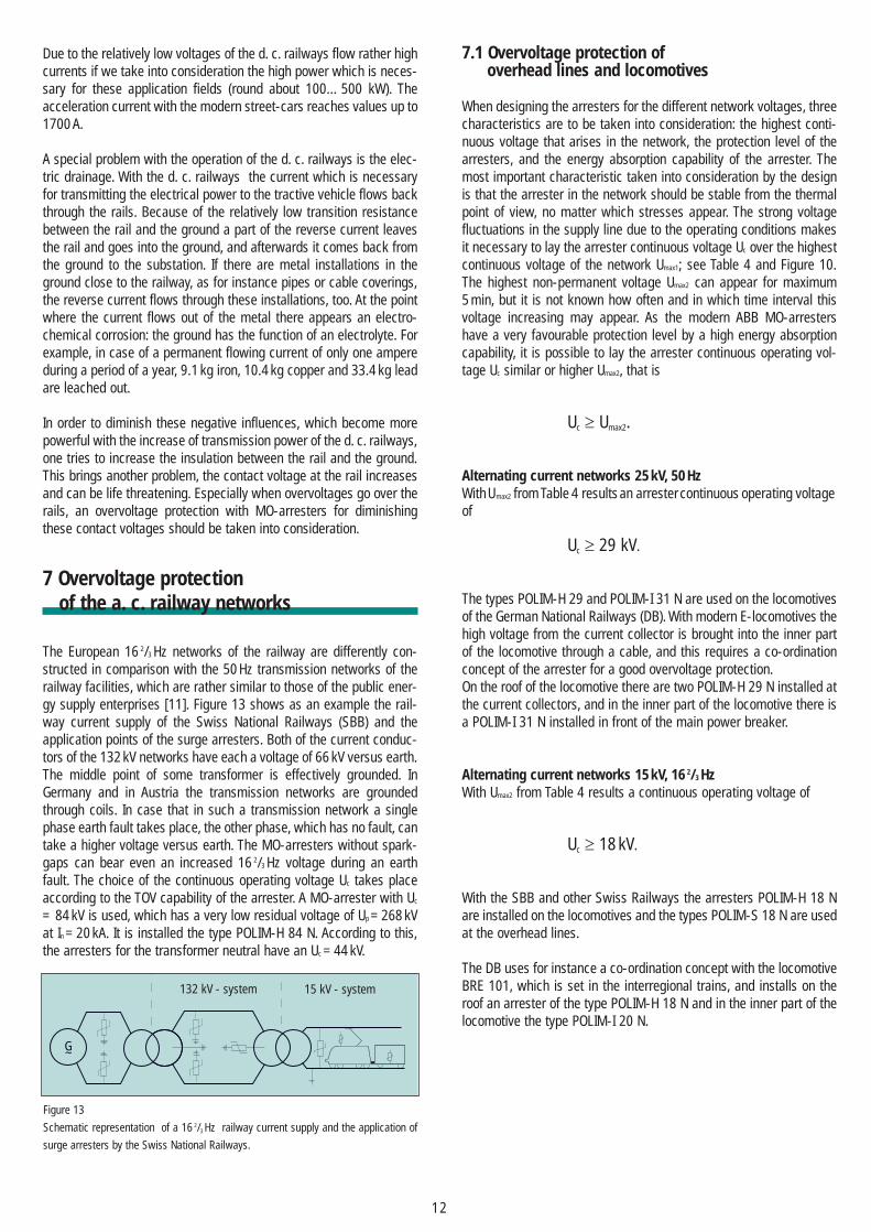
7 Overvoltage protectionof the a. c. railway networks
The European 16 2/3 Hz networks of the railway are differently con-structed in comparison with the 50 Hz transmission networks of therailway facilities, which are rather similar to those of the public ener-gy supply enterprises [11]. Figure 13 shows as an example the rail-way current supply of the Swiss National Railways (SBB) and theapplication points of the surge arresters. Both of the current conduc-tors of the 132 kV networks have each a voltage of 66 kV versus earth.The middle point of some transformer is effectively grounded. InGermany and in Austria the transmission networks are groundedthrough coils. In case that in such a transmission network a singlephase earth fault takes place, the other phase, which has no fault, cantake a higher voltage versus earth. The MO-arresters without spark-gaps can bear even an increased 16 2/3 Hz voltage during an earthfault. The choice of the continuous operating voltage Uc takes placeaccording to the TOV capability of the arrester. A MO-arrester with Uc
= 84 kV is used, which has a very low residual voltage of Up = 268 kVat In = 20 kA. It is installed the type POLIM-H 84 N. According to this,the arresters for the transformer neutral have an Uc = 44 kV.
7.1 Overvoltage protection of overhead lines and locomotives
When designing the arresters for the different network voltages, threecharacteristics are to be taken into consideration: the highest conti-nuous voltage that arises in the network, the protection level of thearresters, and the energy absorption capability of the arrester. Themost important characteristic taken into consideration by the designis that the arrester in the network should be stable from the thermalpoint of view, no matter which stresses appear. The strong voltagefluctuations in the supply line due to the operating conditions makesit necessary to lay the arrester continuous voltage Uc over the highestcontinuous voltage of the network Umax1; see Table 4 and Figure 10.The highest non-permanent voltage Umax2 can appear for maximum5 min, but it is not known how often and in which time interval thisvoltage increasing may appear. As the modern ABB MO-arrestershave a very favourable protection level by a high energy absorptioncapability, it is possible to lay the arrester continuous operating vol-tage Uc similar or higher Umax2, that is
Uc ≥ Umax2.
Alternating current networks 25 kV, 50 HzWithUmax2 from Table 4 resultsan arrestercontinuous operating voltageof
Uc ≥ 29 kV.
The types POLIM-H 29 and POLIM-I 31 N are used on the locomotivesof the German National Railways (DB). With modern E-locomotives thehigh voltage from the current collector is brought into the inner partof the locomotive through a cable, and this requires a co-ordinationconcept of the arrester for a good overvoltage protection.On the roof of the locomotive there are two POLIM-H 29 N installed atthe current collectors, and in the inner part of the locomotive there isa POLIM-I 31 N installed in front of the main power breaker.
Alternating current networks 15 kV, 16 2/3 HzWith Umax2 from Table 4 results a continuous operating voltage of
Uc ≥ 18 kV.
With the SBB and other Swiss Railways the arresters POLIM-H 18 Nare installed on the locomotives and the types POLIM-S 18 N are usedat the overhead lines.
The DB uses for instance a co-ordination concept with the locomotiveBRE 101, which is set in the interregional trains, and installs on theroof an arrester of the type POLIM-H 18 N and in the inner part of thelocomotive the type POLIM-I 20 N.
12
G
132 kV - system 15 kV - system
Figure 13
Schematic representation of a 16 2/3 Hz railway current supply and the application of
surge arresters by the Swiss National Railways.
8 Overvoltage protection of d. c. railway networks
The protection of the electrical railways has the task, in case thatfaults appear, to
– prevent damages at the installation or try to reduce them as muchas possible
– assure the availability of the railway energy supply as much as pos-sible
– prevent or reduce the endangering of life through direct or indirectinfluence of the fault voltages.
Therefore all the stresses which are unacceptable, but however ap-pear in the railway network, are to be removed quickly, totally andselectively. The unacceptable stresses in the network of electrical rail-ways are all types of short circuits, and operational currents, whichlead to an unacceptable warming of the conductor (overhead line orconductor rail).
Short circuits in the supply line installations of the direct current rail-ways appear rather often when compared with the general energysupply of a country. With standard-gauge railways an average of threeshort circuits occur per year per kilometer track, with higher occurances for suburban service lines. The main causes for the shortcircuits are:
– the ride of the traction vehicle in section of the supply line which aregrounded,
– insulation flash-over,– violence (e.g. objects or animals on the supply line, storm, lightning
stroke, vandalism),– damages at the current collector, traction vehicle or in the supply
line installation.
In addition to the usual protective measures in direct current railwayenergy supply for the MV-installations, transformers, power converter,and also for the overhead line and the traction vehicle of the railway,the overvoltage protection is increasingly important.
The reasons for this development are:
– the increased usage of electronic control and information systems,– the increased degree of mashing in the system of the railway ener-
gy supply,– the relative small resistance to jamming of the electronic instal-
lations.
The protection against step-voltages need to be considered more andmore.
In [12] one can read:“The experiences that we made with the application of surge arre-sters are mainly negative experiences when not using protectionmeasures against overvoltages”. The cited publication of HamburgerHochbahn AG states that damages which appear through overvoltageduring a thunder storm or breaker operations have an increasednegative economic effect due to the breaking down of the electronicand data transmission installations.
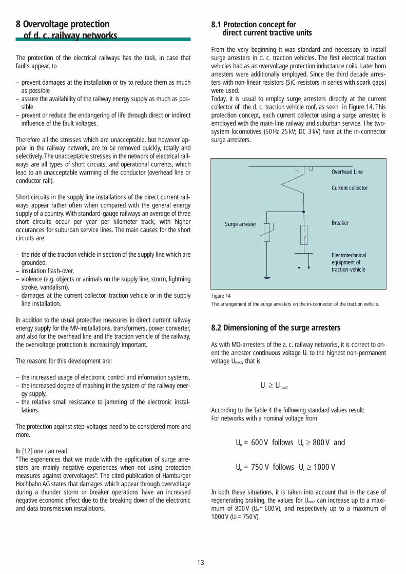
8.1 Protection concept for direct current tractive units
From the very beginning it was standard and necessary to installsurge arresters in d. c. traction vehicles. The first electrical tractionvehicles had as an overvoltage protection inductance coils. Later hornarresters were additionally employed. Since the third decade arres-ters with non-linear resistors (SiC-resistors in series with spark gaps)were used.Today, it is usual to employ surge arresters directly at the currentcollector of the d. c. traction vehicle roof, as seen in Figure 14. Thisprotection concept, each current collector using a surge arrester, isemployed with the main-line railway and suburban service. The two-system locomotives (50 Hz 25 kV; DC 3 kV) have at the in-connectorsurge arresters.
8.2 Dimensioning of the surge arresters
As with MO-arresters of the a. c. railway networks, it is correct to ori-ent the arrester continuous voltage Uc to the highest non-permanentvoltage Umax2, that is
Uc ≥ Umax2
According to the Table 4 the following standard values result:For networks with a nominal voltage from
Un = 600 V follows Uc ≥ 800 V and
Un = 750 V follows Uc ≥ 1000 V
In both these situations, it is taken into account that in the case ofregenerating braking, the values for Umax2 can increase up to a maxi-mum of 800 V (Un = 600 V), and respectively up to a maximum of1000 V (Un = 750 V).
13
Surge arrester
Electrotechnicalequipment oftraction-vehicle
Overhead Line
Current collector
Breaker
Figure 14
The arrangement of the surge arresters on the in-connector of the traction vehicle.
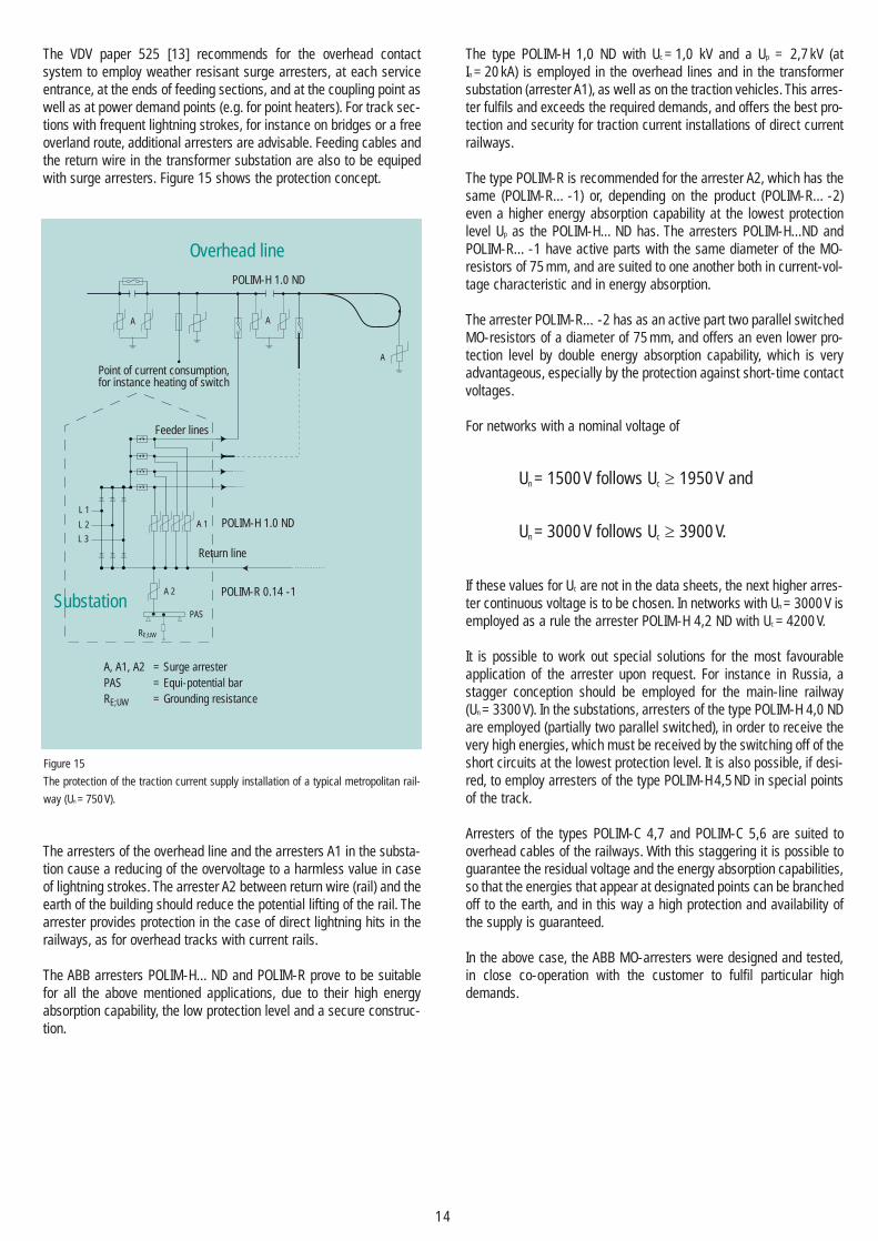
The VDV paper 525 [13] recommends for the overhead contactsystem to employ weather resisant surge arresters, at each serviceentrance, at the ends of feeding sections, and at the coupling point aswell as at power demand points (e.g. for point heaters). For track sec-tions with frequent lightning strokes, for instance on bridges or a freeoverland route, additional arresters are advisable. Feeding cables andthe return wire in the transformer substation are also to be equipedwith surge arresters. Figure 15 shows the protection concept.
The arresters of the overhead line and the arresters A1 in the substa-tion cause a reducing of the overvoltage to a harmless value in caseof lightning strokes. The arrester A2 between return wire (rail) and theearth of the building should reduce the potential lifting of the rail. Thearrester provides protection in the case of direct lightning hits in therailways, as for overhead tracks with current rails.
The ABB arresters POLIM-H…ND and POLIM-R prove to be suitablefor all the above mentioned applications, due to their high energyabsorption capability, the low protection level and a secure construc-tion.
The type POLIM-H 1,0 ND with Uc = 1,0 kV and a Up = 2,7 kV (atIn = 20 kA) is employed in the overhead lines and in the transformersubstation (arrester A1), as well as on the traction vehicles. This arres-ter fulfils and exceeds the required demands, and offers the best pro-tection and security for traction current installations of direct currentrailways.
The type POLIM-R is recommended for the arrester A2, which has thesame (POLIM-R…-1) or, depending on the product (POLIM-R…-2)even a higher energy absorption capability at the lowest protectionlevel Up as the POLIM-H…ND has. The arresters POLIM-H...ND andPOLIM-R…-1 have active parts with the same diameter of the MO-resistors of 75 mm, and are suited to one another both in current-vol-tage characteristic and in energy absorption.
The arrester POLIM-R…-2 has as an active part two parallel switchedMO-resistors of a diameter of 75 mm, and offers an even lower pro-tection level by double energy absorption capability, which is veryadvantageous, especially by the protection against short-time contactvoltages.
For networks with a nominal voltage of
Un = 1500 V follows Uc ≥ 1950 V and
Un = 3000 V follows Uc ≥ 3900 V.
If these values for Uc are not in the data sheets, the next higher arres-ter continuous voltage is to be chosen. In networks with Un = 3000 V isemployed as a rule the arrester POLIM-H 4,2 ND with Uc = 4200 V.
It is possible to work out special solutions for the most favourableapplication of the arrester upon request. For instance in Russia, astagger conception should be employed for the main-line railway(Un = 3300 V). In the substations, arresters of the type POLIM-H 4,0 NDare employed (partially two parallel switched), in order to receive thevery high energies, which must be received by the switching off of theshort circuits at the lowest protection level. It is also possible, if desi-red, to employ arresters of the type POLIM-H 4,5 ND in special pointsof the track.
Arresters of the types POLIM-C 4,7 and POLIM-C 5,6 are suited tooverhead cables of the railways. With this staggering it is possible toguarantee the residual voltage and the energy absorption capabilities,so that the energies that appear at designated points can be branchedoff to the earth, and in this way a high protection and availability ofthe supply is guaranteed.
In the above case, the ABB MO-arresters were designed and tested,in close co-operation with the customer to fulfil particular highdemands.
14
POLIM-H 1.0 ND
Overhead line
Point of current consumption, for instance heating of switch
A A
A
A 1
A 2
PAS
RE;UW
L 1
L 2
L 3
POLIM-H 1.0 ND
POLIM-R 0.14 -1
Feeder lines
Return line
A, A1, A2 = Surge arresterPAS = Equi-potential barRE;UW = Grounding resistance
Substation
Figure 15
The protection of the traction current supply installation of a typical metropolitan rail-
way (Un = 750 V).
15
9 Conclusions
Lightning overvoltage and switching overvoltage are a risk for instal-lations and equipment in the electrical railways. MO-arresters assurea reliable protection against unacceptable overvoltage stress. TheABB arresters with the direct moulding of the silicon housing on theactive part are particularly suitable for the application in railways,especially on the traction vehicles, because of their high security in alloperation cases.During many discussions with the users of surge arresters it was noti-ced that a thorough information and co-operation is welcomed.Especially with the electrical railways is this very important becausethere are particular demands to be fulfilled, and with the modern MO-arresters with silicon housing without spark-gaps new applicationpossibilities may appear. Many individual cases by different railwaynetworks can be solved in this way.An optimal protection concept, taking into consideration the mostfavourable solution from the economical and technical point of view,increases the security and the availability of the electrical facilities ofthe railway current supply.We offer gladly information and calculations to the protection againstovervoltage, which exceed the standard values given above.
Bibliography
[1] Aplication Guidelines Overvoltage ProtectionDimensioning, testing and application of metal oxide surge arresters in medium voltage networks,3 rd revised edition July 1999. ABB High Voltage Technologies Ltd. Wettingen/Switzerland.
[2] F. Greuter et al.: The metal-oxide resistor – at the heart of modern surge arresters; ABB Technik1/89
[3] W.Schmidt: Metalloxid – ein fast idealer Überspannungsableiter; Bulletin SEV/VSE 7/1998, S. 13...20
[4] IEC 60099-4 Edition 1.1 1998-08; Surge arresters – Part 4: Metal-oxide surge arresters withoutgaps for a. c. systems
[5] IEC 61643-1 First Edition 1998-02; Surge protective devices connected to low-voltage power distri-bution systems – Part 1: Performance requirements and testing methods
[6] EN 50123-5; Railway applications-Fixed installations, Part 5: Surge arresters and low-voltage limi-ters for specific use in D. C. systems
[7] EN 50163; Railway applications – Supply voltages of traction systems
[8] IEC TC 37/199/CDV; Amendment 2 to IEC 60099-4, Part 4: metal-oxide surge arresters without gapsfor a. c. systems
[9] K. Lahti, B. Richter, K. Kannus, K. Nousiainen; Seal Integrity Tests on Metal Oxide Surge Arresterswith Polymeric Housings, ISH Montreal 1997
[10] K. Lahti, B. Richter, K. Kannus, K. Nousiainen; Internal Degradation of Polymer Housed Metal OxideSurge Arresters in Very Humid Ambient Conditions, ISH London 1999.
[11] A. Mayer; Überspannungsschutz von Wechselstrom-Bahnnetzen und Bahnfahrzeugen, ABB Technik3/1994
[12] R. Mäkel; Erfahrungen der Verkehrsbetriebe beim Einsatz von Überspannungsableitern, Berichte undInformationen 2/98, Hochschule für Technik und Wirtschaft Dresden (FH).
[13] VDV Schrift 525: Schutz der Fahrstromversorgungsanlagen von Gleichstrombahnen bei Blitzschlag,Entwurf September 1999.
16

CH
HO
S /
AR
364
0 E
ABB Switzerland LtdHigh Voltage TechnologySurge ArrestersJurastrasse 45CH-5430 Wettingen 1
Phone: +41 (0)58 585 29 11Telefax: +41 (0)58 585 55 70
[email protected]/arrestersonline
Creation ZHPrinted in Switzerland 2002-03
LOPO