METAL-OXIDE SURGE ARRESTER PROTECTION OF . com DISTRIBUTION … · · 2014-03-24METAL-OXIDE SURGE...
24
© Copyright 2004 • Hubbell/ Ohio Brass Printed in U.S.A. EU1136-H NOTE: Because Hubbell has a policy of continuous product improvement, we reserve the right to change design and specifications without notice. Customer Service • 210 N. Allen St. • Centralia, MO 65240 • Phone 573-682-5521 • Fax 573-682-8714 METAL-OXIDE SURGE ARRESTER PROTECTION OF DISTRIBUTION SYSTEMS ® ® POWER SYSTEMS, INC. www . ElectricalPartManuals . com
Transcript of METAL-OXIDE SURGE ARRESTER PROTECTION OF . com DISTRIBUTION … · · 2014-03-24METAL-OXIDE SURGE...
© Copyright 2004 • Hubbell/ Ohio Brass Printed in U.S.A. EU1136-HNOTE: Because Hubbell has a policy of continuous product improvement, we reserve the right to change design and specifications without notice.Customer Service • 210 N. Allen St. • Centralia, MO 65240 • Phone 573-682-5521 • Fax 573-682-8714
METAL-OXIDE SURGE ARRESTERPROTECTION
OFDISTRIBUTION SYSTEMS
®®
POWER SYSTEMS, INC.
www . El
ectric
alPar
tMan
uals
. com
2
METAL-OXIDE SURGE ARRESTERPROTECTION OF DISTRIBUTION SYSTEMS
Abstract - Distribution systems traditionally have been protected with silicon-carbide distributionarresters. Even though large protective margins for overhead equipment and adequate marginsfor underground equipment appears to exist, a significant number of equipment failures do occur.
This paper compares the protection of overhead and underground distribution equipment withsilicon-carbide, polymer-housed normal-duty and heavy-duty metal-oxide distribution, and poly-mer-housed metal-oxide riser-pole arresters. Protective margins are calculated using traditionalrate of rise and also considerably higher rate of rise of arrester discharge current. These calcula-tions show that metal-oxide arresters provide substantially improved protection over silicon-carbide distribution arresters for both overhead and underground distribution systems. This holdstrue even for normal-duty MOV arresters compared to heavy-duty silicon-carbide arresters.
INTRODUCTION
The distribution class surge arrester is the most common type of protective device used onpower systems today. Its application typically is limited to systems rated 34.5-kV and lower. Theprimary function of the distribution surge arrester is to protect the insulation of distribution classoil-filled transformers. Other typical applications include the protection of rotating machines anddry-type transformers.
Until recently, the design of the distribution arrester was predicated on the use of a simple multi-gap connected in series with silicon-carbide valve elements. Under continuous energization,system phase-ground voltage was maintained across the series gap element. The size of themulti-gap was maintained approximately proportional to the system voltage to which the arresterwas attached. The gap element sparked over to limit system overvoltages and provided thereseal function after the arrester conducted a half cycle of follow current. The magnitude of thesystem follow current was limited by the silicon-carbide valve elements connected in series withthe multi-gap.
The protection provided to insulation adjacent to the gapped silicon-carbide distribution arresteris a function of both the sparkover characteristic of the arrester gap structure and the dischargevoltage characteristic of the silicon-carbide valve elements.
The intent of this paper is to examine the improved protection provided for distribution systeminsulation by polymer-housed metal-oxide surge arresters. The advantages of the metal-oxidedesign are discussed. In addition, both overhead and underground applications are examined,and comparisons are made between gapped silicon-carbide and gapless metal-oxide arresterprotection.
www . El
ectric
alPar
tMan
uals
. com
3
THE METAL-OXIDE ALTERNATIVE
Three types of Ohio Brass polymer-housed metal-oxide arresters are available for application ondistribution systems. They may be used on overhead lines to improve existing protective mar-gins, or on riser-poles adjacent to underground distribution circuits that cannot be adequatelyprotected by conventional silicon-carbide arresters.
One type is a gapless heavy-duty distribution class surge arrester, the DynaVar Type PDV-100,constructed with 40-mm diameter metal-oxide discs. The PDV-100 has lower protective charac-teristics than the DA-IV heavy-duty gapped silicon-carbide distribution arresters. Because of theexcellent energy-absorbing capability of the metal-oxide material, the PDV-100 arrester units aresmaller than equivalent sizes of the DA-IV. The size differential is most evident on the large-sizeunits, such as the 22-kV MCOV PDV-100 arrester, which is approximately 75 percent of the sizeof the 27-kV duty cycle rated DA-IV equivalent.
The normal-duty polymer-housed MOV arrester, PDV-65, is constructed with 32-mm diametermetal-oxide discs.
Due to the superior protective characteristics of the PDV-65 it is compared throughout the rest ofthe paper to the silicon-carbide DA-IV arrester.
The polymer-housed metal-oxide riser-pole arrester, DynaVar Type PVR, in the study is as-sembled with larger-diameter 48-mm metal-oxide discs. It has the protective characteristics anddurability of an intermediate class arrester. The PVR's protective characteristics are better thanthose of both conventional silicon-carbide and metal-oxide distribution arresters.
A major difference between the normal-duty and heavy-duty arrester designs are the protectivecharacteristics these arresters possess. The heavy-duty distribution arrester offers better protec-tion than normal-duty distribution arresters.
In addition to the protective characteristics there is also a difference in the durability of the heavy-duty and normal-duty arrester designs. Significant among these is the high-current short-durationstrength of these designs. The heavy-duty distribution class arrester has a 100-kA high-currentdischarge capability while the normal-duty arrester only has 65-kA current discharge capability.
www . El
ectric
alPar
tMan
uals
. com
4
METAL-OXIDE ARRESTER APPLICATION
Figure 1 lists several distribution-system voltages and identifies the smallest standard metal-oxide arrester sizes available for application on each system, depending on the grounding effec-tiveness. Note that for an effectively grounded neutral system, the arrester with a maximumcontinuous operating voltage (MCOV) greater than or equal to the maximum line-to neutralvoltage is the recommended application. For noneffectively grounded systems where high volt-ages of longer duration can occur on unfaulted phase arresters, larger arrester sizes are re-quired. For this condition, the arrester's overvoltage capability is utilized. The 11 percent overvolt-age capability (1.11 times MCOV for 2000 hours) and 23 percent overvoltage capability (1.23times MCOV for 30 minutes) of the metal-oxide designs allow minimization of arrester protectivelevels while still maintaining arrester thermal stability during noneffectively grounded system faultconditions.
The above holds true for both the heavy-duty and normal-duty designs.
ADVANTAGES OF METAL-OXIDE ARRESTERSOVER CONVENTIONAL SILICON-CARBIDE
DISTRIBUTION CLASS ARRESTERS
The advantages of the polymer-housed metal-oxide varistor (MOV) arrester designs over theconventional silicon-carbide distribution arrester are described below.
Improved Temporary-Overvoltage Capability
When subjected to temporary power-frequency overvoltages, the high-exponent metal-oxidearrester conducts significantly less current than a comparably rated silicon-carbide distributionclass arrester. If the silicon-carbide arrester is subjected to an overvoltage condition and simulta-neously is forced to spark over, the integrity of the arrester is dependent on the ability of themulti-gap design to successfully interrupt the high power follow currents associated with theovervoltage condition. If the arrester is not able to reseal against the overvoltage condition,failure occurs within a few cycles.
In contrast, at every voltage level, the high-exponent MOV design conducts significantly lesscurrent than does the silicon-carbide equivalent. Even though the MOV arrester might begin toheat up due to the increased flow of current through the arrester, in most cases the current levelsare low enough that thermal stability is maintained when normal system voltage levels are re-turned.
www . El
ectric
alPar
tMan
uals
. com
5
Improved Surge-Duty Capability
The high-exponent characteristics of the MOSA design allow the arrester to conduct less thanone ampere of follow current after an impulse discharge when energized at equivalent ratedvoltage. In contrast, the silicon-carbide arrester conducts over 100 amperes of follow currentwhen forced to spark over with rated voltage applied. Therefore, the MOV arrester is not subjectto restriking failure that the silicon-carbide arrester may experience at normal operating voltages.
In addition, the MOV arrester has much better multiple-surge-withstand capability than a compa-rably rated silicon-carbide arrester. The MOV arrester is more suitable than the distribution classsilicon-carbide arrester for withstanding the duty associated with high-energy capacitor bank orcable applications.
Improved Contamination Performance
This advantage is most prevalent on higher ratings where the silicon-carbide distribution classarrester is most vulnerable to the influences of contamination, which can cause substantial re-duction in sparkover. The gapless MOV arrester is immune to internal problems from externalcontamination.
Simpler Design with Fewer Parts
An examination of cutaway sections reveals the simpler internal construction of the PDV-100 andPVR designs compared to the DA-IV (Figure 2). The design of the normal-duty polymer is similarexcept for smaller block and housing diameters.
Resistance to Leaking and Safe Failure Mode
The major cause of arrester failure is moisture ingress. The Ohio Brass polymer-housed arrestermakes it nearly impossible for moisture to enter the unit so failures due to leaking are eliminated.
In the extremely unlikely event of an arrester failure due to system conditions the polymer-housed PDV-100 and PVR arresters incorporate fault current withstand capabilities ranging from20-kA for 10 cycles to 500 amps for 90 cycles for the PVR and 120 cycles for the PDV-1 00arresters.
The polymer housed PDV-65 arrester has fault current withstand capabilities from 1 0-kA for 10cycles to 500 amps for 120 cycles.
Improved Protective Characteristics
The remainder of this paper is concerned with the protective characteristics of polymer-housedmetal-oxide arresters compared with equivalently sized silicon-carbide arresters. Specific over-head and underground applications are examined, comparing the standard arrester characteris-tics and examining the advantages of metal-oxide over silicon-carbide designs.
www . El
ectric
alPar
tMan
uals
. com
6
Comparison of Protective Characteristics
Figure 3 compares the standard catalog protective characteristics of the DA-IV silicon-carbidedistribution arrester, the PDV-100 heavy duty arrester, the PDV-65 normal-duty arrester, and thePVR riser-pole arrester. In addition to front-of-wave sparkover for the gapped DA-IV design, 0.5-microsecond 10-kA IR also is included in this protective characteristics comparison. Three typicaldistribution system voltages are examined: 13.2, 24.9 and 34.5-kV.
Notice the normal-duty MOV PDV-65 arrester gives equal or superior protection when comparedto the heavy-duty DA-IV unit in nearly all cases.
For insulation-coordination purposes, the arrester front-of-wave characteristic historically iscompared with the transformer's chopped-wave strength. Similarly, the BIL protective margin isderived from the transformer BIL strength and the higher of either the 1.2/50 impulse sparkoveror the 8/20 discharge voltage, typically for 10- or 20-kA surges. For this study, the 10-kA dis-charge voltage level is used.
For the 13.2-kV system the 8.4-kV normal-duty PDV-65 arrester front-of-wave and impulse levelsare 8 percent and 20 percent lower, respectively than the levels of the 10-kV DA-IV arrester.
The 8.4-kV heavy-duty, PDV-100 arrester's front-of-wave and impulse protective levels are 20percent and 30 percent lower, respectively, than those of the 10-kV DA-IV arrester. Even betterinsulation protection is provided by the 8.4-kV PVR arrester with 40 percent lower protectivelevels than the 10-kV DA-IV arrester. These arrester sizes are equally applicable to 13.8-kVsystems.
For the 24.9-kV system, the 15.3-kV MOV normal-duty PDV-65 arrester provides 12 percentlower front-of-wave and 1 percent lower impulse protection than the equivalent 18-kV heavy-dutysilicon-carbide DA-IV.
The 15.3-kV MOV PDV-100 arrester provides 22 percent lower front-of-wave and 10 percentlower impulse protection than the equivalently sized 18-kV DA-IV silicon-carbide arrester. The15.3-kV MOV PVR arrester provides 41 percent lower front 28 percent lower impulse protectivelevels than the 18-kV DA-IV silicon-carbide arrester.
For the 34.5-kV system, the 22-kV PDV-65 and PDV-100 MOSA and 22-kV PVR riser polearresters provide protective-level reductions similar to those described for the 24.9-kV system.
www . El
ectric
alPar
tMan
uals
. com
7
OVERHEAD DISTRIBUTION PROTECTION
First, let's examine the application of arresters to overhead distribution systems. Figure 4 lists acomparison of three distribution system voltages, their applicable BIL levels, and the correspond-ing arresters used on each system. For example, the 24.9-kV system typically is designed foreither 125 or 150kV BIL and is protected by 1 8-kV conventionally rated silicon-carbide arrestersor by 15.3-kV MCOV metal-oxide arresters.
The important point to note is that, as the system voltage increases, the size of the arrester usedon that system increases proportionately. For example, the 24.9-kV system is 1.9 times largerthan the 13.2-kV system, and the size of the corresponding arrester increases 1.8 times. How-ever, depending on the specific applications, the BIL levels typically do not increase proportion-ately as the system voltage increases. Therefore, as the system voltage increases, the protectivemargins offered by the surge arresters typically decrease.
Before looking at specific examples, we should point out that the minimum acceptable protectivemargin on distribution chopped-wave and BIL insulation strength is typically 20 percent. In theanalysis that follows, calculated protective margins for overhead lines of 100 percent are quitecommon. In spite of many nominal protective margins exceeding 100 percent, an estimated100,000 transformers fail each year due to insulation failure at an estimated cost to the industryof $35 million.
The question arises, "Why are so many transformers failing?"
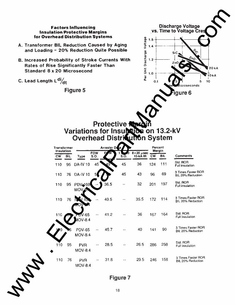
Figure 5 lists some factors that can influence the effective protective margin that exists on anoverhead distribution transformer.
First, studies have shown that the BIL of a transformer can be lowered by aging and loadingeffects. A 20 percent reduction in the BIL strength is quite possible, reducing the effective BILprotective margin.
Second, an area of concern is the expected rate of rise of a lightning discharge. The calculatedmargin for BIL assumes an 8/20 lightning discharge. Lightning studies indicate that stroke cur-rents significantly faster than the assumed 8/20 waveshape are very probable. In fact, one studyreveals that over half of the recorded strokes had rates of rise approximately three times fasterthan expected. In addition, 15 percent of the recorded strokes had recorded times to crest of onemicrosecond or less (7, 8).
Third, a factor affecting protective margins is the lead length voltage drop, L di/dt. The rule ofthumb is to assume a lead voltage of 1.6-kV per foot of lead length, which is added to the ar-rester discharge voltage. This assumes a lead inductance of 0.4 microhenries per foot and alinear rate of rise for the current wave of 4-kA per microsecond. Although this is conservative fora standard 1 0-kA 8/20 wave, higher lead voltages could result for faster current rates of rise andhigher current magnitudes (1, 5).
www . El
ectric
alPar
tMan
uals
. com
8
Figure 6 illustrates one advantage of the metal-oxide arrester over a conventional silicon-carbidedesign. When subjected to faster-than-normal rates of rise of current, the metal-oxide designexhibits a slower rate of discharge voltage turnup. For these curves, the 8/20 discharge voltagelevels for both a metal-oxide and a silicon-carbide disc have been normalized at the 10-kA, 8/20discharge current level. For a three-times-faster rate of rise of current, the silicon-carbide dis-charge voltage level increases approximately 20 percent while the metal-oxide voltage levelincreases only 10 percent. This effect is used in the upcoming examination of protective marginsfor 13.2, 24.9, and 34.5-kV systems.
Figures 7 through 11 have been developed to allow an examination of calculated protectivemargins and how these margins are affected by faster rates of current rise, BIL reduction due toaging and overloading, and variations in arrester protective characteristics as a function of therate of rise of the current discharges. Note that in all the calculations the effect of lead lengthvoltage drop, L di/dt, has been neglected. As mentioned before, lead drop can be significant,particularly if faster rate-of-rise discharges are considered.
Figure 7 examines the protective margin variations for a 13.2-kV overhead distribution systemwith 95-kV BIL and 110-kV chopped-wave insulation levels. The first two conditions show protec-tive margins afforded by a 10-kV silicon-carbide DA-IV arrester.
Condition 1 assumes full insulation strength and standard voltage and current rates of rise. Thisyields excellent chopped-wave and BIL protective margins of 124 percent and 111 percent,respectively.
Condition 2 assumes both a 20 percent BIL reduction and a three-times-faster rate of rise.Chopped-wave and BIL margins are reduced to 96 percent and 69 percent, respectively, withoutany consideration for lead length voltage drop.
Conditions 3 and 4 examine an 8.4-kV MCOV heavy-duty PDV-100 MOV arrester applicationand correspond to Conditions 1 and 2, respectively, for the 10-kV DA-IV silicon-carbide arrester.
The full insulation and standard rate of rise in Condition 3 yield margins around 200 percent. Thethree-times-faster rate of current rise in Condition 4 results in a 10 percent increase in the 10-kAdischarge voltage level of the metal-oxide distribution arrester, compared to 15 to 20 percentincrease for the silicon-carbide design. For Condition 4, which also includes a 20 percent BILreduction, the chopped-wave and BIL margins are 172 percent and 114 percent respectively.
Conditions 5 and 6 relate to the normal-duty PDV-65 MOV arrester. They show the PDV-65 MOVarrester gives superior protection under the same circumstances applied to the heavy-duty DA-IVarrester. The margins for the PDV-65 MOV are 141 and 90 respectively under the most severeconditions shown.
www . El
ectric
alPar
tMan
uals
. com
9
Conditions 7 and 8 of Figure 7 examine the protection afforded by the 8.4-kV MCOV PVR metal-oxide riser pole arrester under conditions similar to those described for the 8.4-kV MCOV PDV-100 heavy-duty MOV arrester. Under standard conditions, the 8.4-kV PVR arrester provides 286percent margin for chopped-wave and 258 percent for BIL. Assuming the three-times-faster rateof rise and 20 percent BIL reduction, the 8.4-kV PVR arrester still provides 246 percent and 158per-wave and BIL margins, respectively.
For the 13.2-kV system, the 10-kV DA-IV, the 8.4-kV PDV-65 and the PDV-100 metal-oxidearresters provide more than adequate protective margins, even when the effects of insulationaging and faster rates of rise are included. However, for higher-voltage distribution systems, theeffects of aging and faster rates of rise can produce much lower protective margins. The im-proved short-time characteristics of the metal-oxide arresters can be utilized to maintain ad-equate margins. Also, lead length effects will influence protective margins.
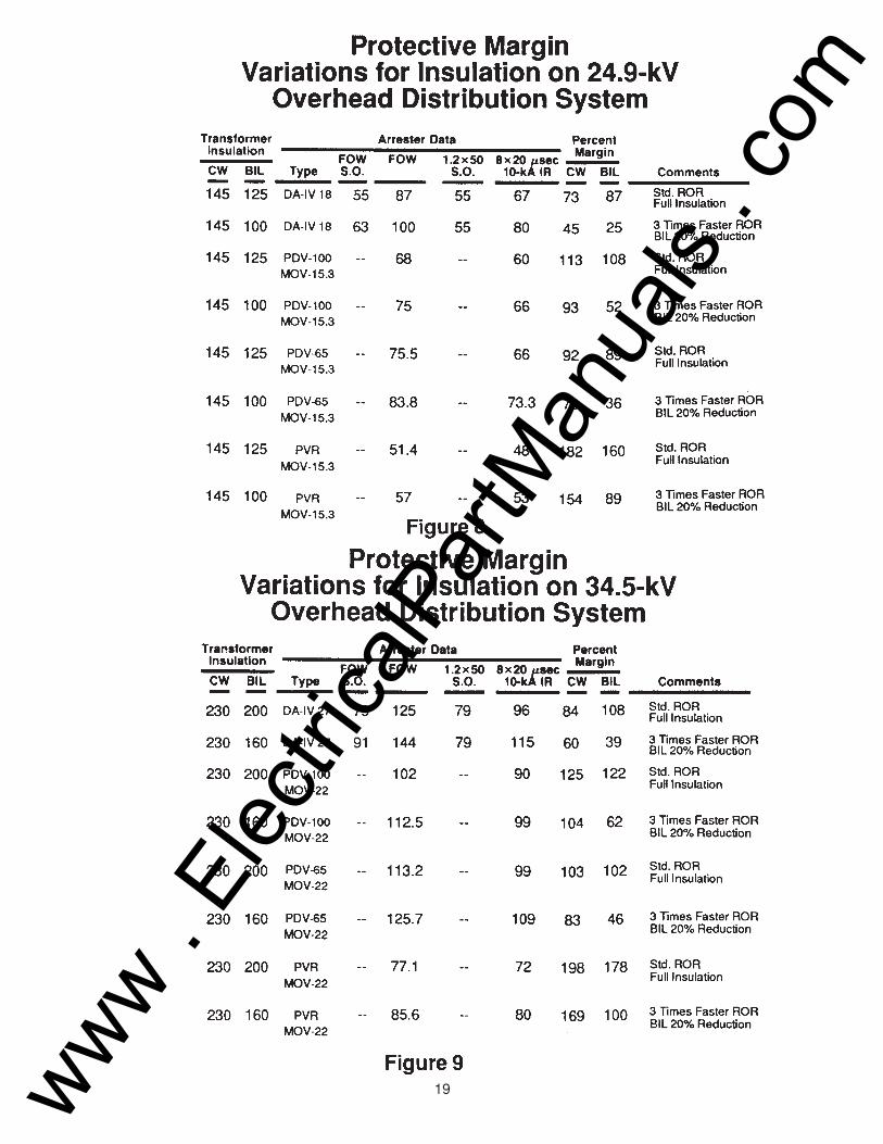
Figure 8 examines protective margin variations for a 24.9-kV overhead distribution system with125-kV BIL and 145-kV chopped-wave insulation strength. Comparison of Condition 1 (full BILinsulation and standard rate of rise) with Condition 2 (20 percent BIL reduction and three times-faster rate of rise) reveals that the 18-kV rated, DA-IV arrester's protective margin is reduced to amarginal condition, neglecting line lead drop.
In comparison, the 15.3-kV MCOV PDV-100 distribution arrester provides 93 percent chopped-wave and 52 percent BIL margins under the above worst-case conditions. Even the PDV-65arrester gives 73 percent chopped-wave and 36 percent BIL margins under the worst case condi-tions. As expected, even better protection is provided by the 15.3-kV MCOV PVR arrester.
Figure 9 examines the protective margin variations for a 34.5-kV overhead distribution systemwith 200-kV BIL and 230-kV chopped-wave insulation levels. The first two conditions are similarto those discussed for Figures 7 and 8. This time, protection is provided by a 27-kV DA-IV sili-con-carbide arrester. Note that the BIL protective margin is reduced from 108 percent to 39percent as a result of a 20 percent reduction in BIL strength and the effects of a three-times-faster rate of rise.
The improved protective characteristics of the 22-kV MCOV PDV-65, PDV-100 and PVR arrest-ers show greater protective margins under the worst case conditions.
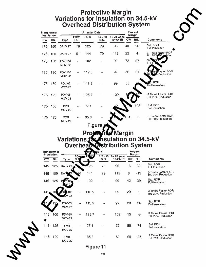
Figure 10 examines the 34.5-kV system with lower insulation levels of 150-kV for BIL and 175-kVfor chopped wave. For the same 27-kV silicon-carbide DA-IV arrester, the BIL protective marginis reduced from 56 percent to 4 percent as a result of insulation aging and faster rate-of-riseeffects.
Advantage can be taken of the 22-kV MCOV PDV-100 and PVR arresters short-time characteris-tics. For these arresters the BIL protective margin decreases from 67 percent to 21 percent and108 percent to 50 percent, respectively. The PDV-65 MOV arrester BIL protective margins in thiscase reduces from 52 percent to 10 percent. For this insulation level, adequate protection can befurnished by PDV-100 and PVR metal-oxide designs.
www . El
ectric
alPar
tMan
uals
. com
10
Figure 11 shows the 34.5-kV system with even lower insulation levels of 1 25-kV for BIL and 145-kV for chopped-wave. The BIL protective margin when using a heavy-duty DA-IV arrester forstandard conditions is only 30 percent. Including the effects of either the reduced insulation dueto aging or faster rates of voltage rise causes the BIL margin to reduce below the minimum 20percent level. Even the 22-kV PDV-100 arrester provides only a one percent protective marginunder the worst scenario.
However, the 22-kV PVR arrester has a 74 percent BIL margin for standard conditions. Theeffects of aging and faster rates of rise still show this arrester to have an adequate BIL margin of25 percent.
UNDERGROUND DISTRIBUTION PROTECTION
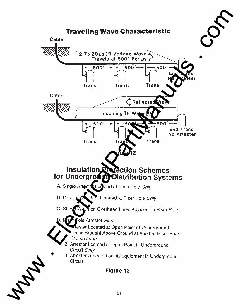
Another important arrester application is protection of underground distribution circuits and theequipment connected to these circuits. Cable circuits traditionally are protected with arresters atthe riser-pole to prevent lightning surges from damaging the cable terminator, the cable, or theconnected equipment. Either silicon-carbide or metal-oxide arresters of proper voltage ratingeasily protect the terminator and the cable insulation but introduce a traveling-wave voltage in thecable. The traveling-wave traverses the cable at a velocity of about 500 feet per microsecond,and it reflects positively if the far end of the cable presents a high impedance, such as a trans-former or an open switch. If arrester protection is not applied at the open point, the positivereflection produces a nearly doubled voltage that can endanger the cable and connected equip-ment (Figure 12).
For a gapless metal-oxide arrester, the traveling wave magnitude is a function of the arrester'sdischarge voltage characteristics. The arrester's values for 0.5-microsecond 1 0-kA dischargevoltage and 8/20 10-kA discharge voltage are doubled when calculating the protective marginswith protection at the riser pole only.
With a gapped silicon-carbide arrester at the riser pole, the arrester's values for front-of-wavesparkover and 8/20 10-kA discharge voltage are doubled when calculating protective margins.
Some insulation protective methods for underground distribution circuit protection are summa-rized in Figure 13. For 13.2 and 1 3.8-kV underground systems, a single arrester located at theriser pole normally provides adequate protective margin to cable-connected equipment (2). Forhigher-voltage systems, protection only at the riser pole may not be adequate.
The addition of an overhead shield wire extending half a mile from the riser pole location sub-stantially reduces the probability of direct lightning strokes on the phase conductors near the riserpole. This reduces the expected discharge-current magnitudes in the riser-pole arrester. In addi-tion, the rate of rise of voltage surges at the riser pole is reduced because of the elimination ofclose-in strokes. Discharge currents can be limited to 5-kA by proper shielding of the overheadconductor adjacent to the riser pole.
www . El
ectric
alPar
tMan
uals
. com
11
For higher-voltage distribution circuits, an arrester only at the riser pole may not provide ad-equate protection for connected underground equipment of normally used BIL (3). Therefore,adequate protection can be obtained only by providing additional arrester protection in the under-ground circuit. This can be avoided only if there is no reflection point, such as on a system usingclosed-loop protection where both ends of the loop are protected by arresters and the loop isnever broken.
A common protection method for high-voltage distribution systems is to locate one arrester at theriser pole and another arrester at the reflection point, which could be the end transformer or anopen tie point. With this method, the maximum voltage developed in the underground cable is acombination of the characteristics of both arresters, and it is higher than the maximum voltage ateither end of the cable.
The best protection method for cable-connected equipment is to locate one arrester at the riserpole and another arrester at each piece of equipment. This alternative normally is not necessaryunless each equipment location becomes an open reflection point in the underground circuit.
We will explore the protective margins available for different types of arresters used only at theriser pole, and for 34.5-kV systems with arresters at the riser pole and at the reflection point inthe cable circuit. With silicon-carbide arresters at the reflection point, the voltage must rise tosparkover for the arrester to operate. Therefore, this becomes the maximum voltage at the reflec-tion point. The traveling-wave voltage produced by the riser-pole arrester and the surge imped-ance of the cable limit the discharge current in the arrester at the reflection point to values lessthan 5-kA unless the cable is very short. Therefore, for a silicon-carbide arrester the dischargevoltage is less than the sparkover. For a metal-oxide arrester, however, the elimination of the gapmakes the protection dependent only on the discharge voltage.
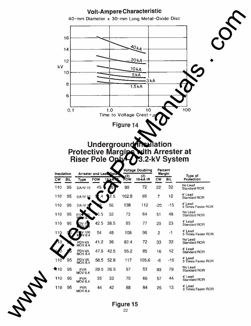
Figure 14 shows the discharge voltage as a function of time to voltage crest for discharge cur-rents from 1.5-kA through 40-kA for a typical 40-mm diameter metal-oxide distribution arresterdisc. This is a more detailed presentation of the phenomenon shown in Figure 6. The dischargevoltages for the various currents shown at a time of about 6 microseconds to voltage crest wouldbe the values published for discharge voltage for an 8/20 current wave. The equivalent front-of-wave protective level normally published is the value for a 10-kA wave fast enough to produce adischarge voltage cresting in 0.5 microseconds. Since the arrester at the reflection point carriesdischarge current less than 5-kA, for calculating the margin of protection for the equipment at theopen end of the cable reasonable discharge voltages would be those at 5-kA for 34.5-kV sys-tems and at 3-kA or less for 24.9 and 13.2-kV systems.
www . El
ectric
alPar
tMan
uals
. com
12
Figures 15 through 17 contain analyses of protective margins obtainable with silicon-carbidedistribution arresters, metal-oxide riser-pole arresters, and metal-oxide distribution arresters for 13.2-kV (or 13.8-kV) systems with 95-kV BIL, 24.9-kV systems with 125-kV BIL, and 34.5-kVsystems with 150-kV BIL. In each case, the traditional calculation is done comparing front-of-wave sparkover or 0.5-microsecond discharge voltage with chopped-wave withstand and stan-dard rate of voltage rise using 10-kA IR and no arrester lead drop with BIL, assuming doubling atthe reflection point. The second analysis in each case assumes a 4-foot lead with a voltage dropof 1.6-kV per foot, as suggested in the ANSI application guide (1). This lead drop may be slightlyhigh for 10-kA waves with standard rate of rise. The third analysis assumes a three-times-fasterrate of rise, as discussed previously for overhead protection, and again a 4-foot lead. In thiscase, a lead drop of 3.2-kV per foot is used because of the steeper rate of rise of current (5).
The arrester lead drop often is neglected in overhead protection calculations because marginsare high. It is dangerous, however, to neglect this effect when protecting cable-connected equip-ment because the margins are much tighter. The analyses show that lead length effects can bevery important and that efforts should be made to keep line and ground leads in series with thearrester as short as possible.
Figure 15 shows that the adequate margin calculated for a standard DA-IV silicon-carbide distri-bution arrester, while assuming standard rate of rise and no lead length, disappears when asteeper rate of rise and some lead are assumed. The PVR arrester has comfortable margins inessentially all cases. Since the recommendation of a 20 percent margin in the normal calculationis made partly because of contingencies such as lead length and high rate of rise, the full marginprobably is not needed for the assumed lead length and steep rise, because some attenuation ofthe traveling wave in the cable occurs.
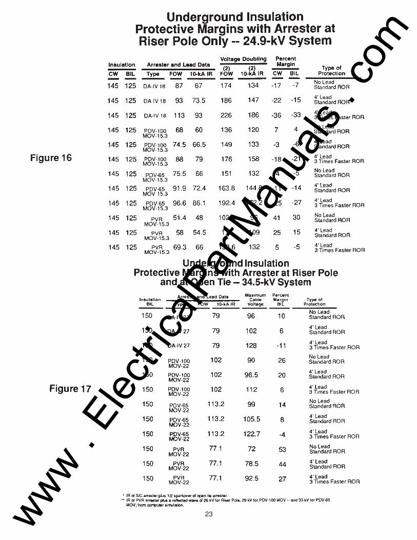
Figure 16 shows that for a 24.9-kV system, the DA-IV arrester does not provide adequate mar-gins for protecting 125-kV BIL cable-connected equipment. Similarly, the PDV-65 and PDV-100arresters with 15.3-kV MCOV give very small protective margins (or negative margins in the caseof the PDV-65 arrester), even if no lead length and standard rate of rise are assumed. The PVRarrester with 15.3-kV MCOV shows adequate margins if lead length is kept very short.
Figure 17 examines the protection of cable-connected equipment with an arrester at the riserpole and also at the open tie point or end transformer. Adequate protection cannot be obtainedwith an arrester only at the riser pole for 150-kV BIL.
www . El
ectric
alPar
tMan
uals
. com
13
With an arrester at the riser pole and at the open tie, the voltage at the open-tie transformer isthe protective level of the arrester at that point. In the case of the silicon-carbide arrester, theprotective level is the front-of-wave sparkover because the discharge current is low enough thatthe discharge voltage is less than sparkover unless the cable is very short. The voltage at inter-mediate points in the cable is the discharge voltage of the riser-pole arrester plus the reflectedwave, equal to one-half the sparkover of the open-tie arrester. This analysis shows that with thesilicon-carbide distribution arrester, adequate protection is not easily obtained even with arrestersat both ends of the cable, particularly if significant lead length and higher rate of rise of currentthrough the riser-pole arrester are assumed.
Similar analyses are shown for the metal-oxide riser-pole and distribution arresters. In this case,the arrester at the open tie also creates a reflected wave that adds to the incoming travelingwave of discharge voltage from the riser-pole arrester. The value of this reflected wave is noteasily calculated. The values used in Figure 17 are based on a computer simulation (6). Thisanalysis shows that PDV-100 and PVR metal-oxide arresters can provide adequate margins forequipment connected throughout the cable length with arresters at the riser pole and the opentie, even if substantial lead length and faster rate of current rise through the riser-pole arresterare assumed.
As can be seen from the above examples it is imperative that the line and ground leads of thearrester be kept as short as possible. There are methods in which the line and ground leads canbe virtually eliminated from the protective margin calculations. First we need to understand whatconstitutes line and ground leads.
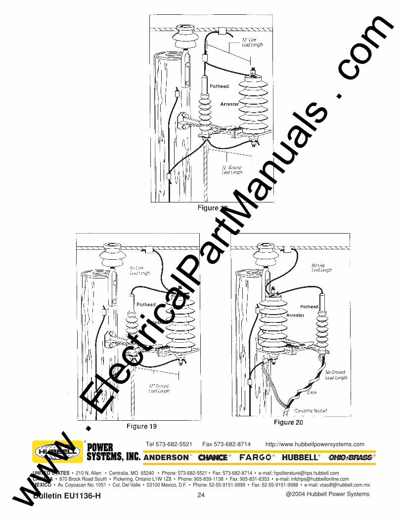
Figure 18 shows a riser-pole configuration with 12 inches each of line and ground lead. For theline and ground lead to add to the discharge voltage of the arrester it must meet both of thefollowing criteria: the lead must be electrically in parallel with the equipment being protected andit must carry full arrester discharge current. As can be seen in Figure 18 the lightning dischargecurrent path will be through the 12 inch line and ground leads and these are in parallel with theequipment being protected.
Figure 19 shows a configuration to eliminate line lead from the protective margin calculations. Inthis case the lead from the overhead conductor is attached first to the line terminal of the arresterthen to the cable terminator. In this case the lead from the overhead conductor to the arrester isnot electrically in parallel with the equipment being protected and so does not add to the dis-charge voltage the equipment sees. No change has been made in the ground lead in this situa-tion so this 12 inches of ground lead does still add to the discharge voltage of the arrester.
www . El
ectric
alPar
tMan
uals
. com
14
Figure 20 shows an arrangement eliminating both the line and ground leads from the calculationsin this case the concentric neutral from the cable is attached directly to the ground lead of thearrester. In this case the discharge voltage which will be seen by the cable termination is only thedischarge voltage of the arrester itself.
CONCLUSIONS
The protective margins arresters provide distribution equipment have been examined for stan-dard conditions and also with higher rates of rise, and in some cases with reduced BlLs fromaging of transformers. This analysis shows that Ohio Brass' polymer housed metal-oxide arrest-ers provide substantially better protection than silicon-carbide distribution arresters for overheadand underground distribution equipment. The advantage is emphasized when higher rates ofcurrent rise than the standard 8/20 discharge current wave are assumed.
www . El
ectric
alPar
tMan
uals
. com
15
REFERENCES
(1) American National Standards Institute, “Guide for the application of valve-type surge arrest-ers for alternating-current systems,” C62.2-1981.
(2) IEEE Committee Report, “Surge protection of cable-connected distribution equipment onunderground systems,” IEEE Transactions on Power Apparatus and Systems, vol. PAS-89,pp. 263-267, February 1970.
(3) IEEE Committee Report, “Surge protection of cable-connected equipment on higher voltagedistribution systems,” IEEE Transactions on Power Apparatus and Systems, vol. PAS-100,pp. 154-157, January 1981.
(4) E. C. Sakshaug, “Influence of rate-of-rise on distribution arrester protective characteristics,”IEEE Transactions on Power Apparatus and Systems, vol. PAS-98, pp. 519-526, March/April 1979.
(5) S. S. Kershaw, Jr., and C. R. Clinkenbeard, “Discharge voltage of arrester connecting leadwires,” IEEE Transactions on Power Apparatus and Systems, vol. PAS-93, pp. 226-232,1974.
(6) S. L. Smith, J. J. Burke, and E. C. Sakshaug, “The application of gapless arresters on under-ground distribution systems,” presented at IEEE Conference on Overhead and UndergroundTransmission and Distribution, Atlanta, GA, April 1979.
(7) N. Hylten - Cavallius and A. Stromberg, “Amplitude, time to half-value, and steepness oflightning currents,” ASEA Journal, vol. 29,1956.
(8) M. Darveniza, “Research into lightning protection of distribution systems,” IEEE Transactionson Power Apparatus and Systems, vol. PAS-103, pp. 673-681, January/May 1984.
www . El
ectric
alPar
tMan
uals
. com

16www . El
ectric
alPar
tMan
uals
. com

17www . El
ectric
alPar
tMan
uals
. com
18www . El
ectric
alPar
tMan
uals
. com
19www . El
ectric
alPar
tMan
uals
. com
20www . El
ectric
alPar
tMan
uals
. com
21www . El
ectric
alPar
tMan
uals
. com
22www . El
ectric
alPar
tMan
uals
. com
23www . El
ectric
alPar
tMan
uals
. com
24
®
POWER SYSTEMS, INC.
UNITED STATES • 210 N. Allen • Centralia, MO 65240 • Phone: 573-682-5521 • Fax: 573-682-8714 • e-mail: [email protected] • 870 Brock Road South • Pickering, Ontario L1W 1Z8 • Phone: 905-839-1138 • Fax: 905-831-6353 • e-mail: [email protected] • Av. Coyoacan No. 1051 • Col. Del Valle • 03100 Mexico, D.F. • Phone: 52-55-9151-9999 • Fax: 52-55-9151-9988 • e-mail: [email protected]
®®® ®™
Tel 573-682-5521 Fax 573-682-8714 http://www.hubbellpowersystems.com
Bulletin EU1136-H @2004 Hubbell Power Systemswww . El
ectric
alPar
tMan
uals
. com