RT-Link: A Time-Synchronized Link Protocol for …agr/resources/publications/rt_link_TR05...RT-Link:...
13
RT-Link: A Time-Synchronized Link Protocol for Energy Constrained Multi-hop Wireless Networks Anthony Rowe, Rahul Mangharam, Raj Rajkumar Electrical and Computer Engineering Department, Carnegie Mellon University, Pittsburgh Technical Report CMU-ECE-TR05-08 Abstract Multi-hop wireless networks of embedded nodes facilitate applications in industrial control, surveillance and inventory tracking. Our focus is on low-cost large-scale deployments where nodes need to be battery-powered with predictable network lifetimes and applications require bounded end-to- end delay. An effective approach to such energy-constrained networks is to operate at low duty cycles and maximize the shutdown interval between packet exchanges. The pri- mary challenge is in coordinating transmissions so they are collision-free while minimizing the duration the nodes are active. RT-Link is a time-synchronized link protocol for fixed and mobile embedded radios. We identify three key observa- tions in the design and deployment of RT-Link: (a) RT-Link offers predictable network lifetime with bounded end-to-end delay. (b) Achieving global time synchronization is both eco- nomical and convenient for indoor and outdoor deployments. (c) Due to interference between nodes, our experiments con- firm that nodes with the same schedule must be spaced by a minimum of 3 hops. Furthermore, to minimize end-to-end de- lay, it is more important to order time slots than to minimize the number of time slots. RT-Link has been deployed on net- works with more than 30 custom embedded nodes and uses the IEEE 802.14.5 physical layer. It outperforms energy- efficient protocols such as B-MAC and S-MAC in throughput, energy consumption and end-to-end delay. 1. Introduction Networks of embedded wireless nodes provide a versatile platform for applications in industrial control, surveillance and inventory tracking. The purpose of such networks is to gather data and deliver it across one or more hops to at least one gateway. The principal requirements are low-cost battery powered radios, minimal configuration on set up with simple and scalable energy-efficient protocols for predictable net- work lifetime and bounded end-to-end message delay. The following deployment scenarios motivate the need for net- works of embedded nodes with such requirements: • Industrial Control Networks: In chemical and automo- bile plants, remote control of machinery and access to performance data requires reliable real-time communi- cation. In such environments, it is necessary that nodes do not require infrastructure for data and power as such provisioning may be both impractical and expensive. • Surveillance and Monitoring Networks: Networks of embedded cameras for monitoring motion and intrusion require bounded end-to-end delay to the gateway and deterministic peak throughput for intermittent transfer of captured images. • Inventory Tracking and Reporting: Networks to classify and locate assets need to be scalable and must operate in a variety of multi-hop wireless topologies. An effective approach to energy-efficient service for applica- tions with periodic and aperiodic flows is to operate all nodes at low duty cycles so as to maximize the shutdown intervals between packet exchanges. The two fundamental challenges in delivering delay-bounded service in such networks are (a) coordinating transmissions so that all active nodes commu- nicate in a tightly synchronized manner and (b) ensuring all transmissions are collision-free. Time synchronization is im- portant because it tightly packs the activity of all nodes so that they may maximize a common sleep interval between activities. Furthermore, it provides guarantees on timeliness, throughput and network lifetime for end-to-end communica- tion. Such assurances are only possible when the link is re- liable and collision-free. It is therefore the responsibility of the link layer protocol to provide exclusive and interference- free access to the shared wireless channel and a mechanism to coordinate sleep intervals of all nodes. The focus of this paper is on RT-Link, a time-synchronized link layer proto- col for collision-free and energy-efficient real-time service over multi-hop wireless networks. RT-Link facilitates dy- namic admission of both fixed and mobile nodes into a tightly synchronized regime. It schedules nodes in time slots such that concurrent transmitters do not interfere with each other and the activity of all nodes are coordinated to maximize the sleep duration. Finally, RT-Link maintains contention-free operation by employing an online and automatic link conflict detection and resolution scheme. Such a scheme is useful
Transcript of RT-Link: A Time-Synchronized Link Protocol for …agr/resources/publications/rt_link_TR05...RT-Link:...
RT-Link: A Time-Synchronized Link Protocol for Energy ConstrainedMulti-hop Wireless Networks
Anthony Rowe, Rahul Mangharam, Raj RajkumarElectrical and Computer Engineering Department, Carnegie Mellon University, Pittsburgh
Technical Report CMU-ECE-TR05-08
Abstract
Multi-hop wireless networks of embedded nodes facilitateapplications in industrial control, surveillance and inventorytracking. Our focus is on low-cost large-scale deploymentswhere nodes need to be battery-powered with predictablenetwork lifetimes and applications require bounded end-to-end delay. An effective approach to such energy-constrainednetworks is to operate at low duty cycles and maximizethe shutdown interval between packet exchanges. The pri-mary challenge is in coordinating transmissions so they arecollision-free while minimizing the duration the nodes areactive. RT-Link is a time-synchronized link protocol for fixedand mobile embedded radios. We identify three key observa-tions in the design and deployment of RT-Link: (a) RT-Linkoffers predictable network lifetime with bounded end-to-enddelay. (b) Achieving global time synchronization is both eco-nomical and convenient for indoor and outdoor deployments.(c) Due to interference between nodes, our experiments con-firm that nodes with the same schedule must be spaced by aminimum of 3 hops. Furthermore, to minimize end-to-end de-lay, it is more important to order time slots than to minimizethe number of time slots. RT-Link has been deployed on net-works with more than 30 custom embedded nodes and usesthe IEEE 802.14.5 physical layer. It outperforms energy-efficient protocols such as B-MAC and S-MAC in throughput,energy consumption and end-to-end delay.
1. Introduction
Networks of embedded wireless nodes provide a versatileplatform for applications in industrial control, surveillanceand inventory tracking. The purpose of such networks is togather data and deliver it across one or more hops to at leastone gateway. The principal requirements are low-cost batterypowered radios, minimal configuration on set up with simpleand scalable energy-efficient protocols for predictable net-work lifetime and bounded end-to-end message delay. Thefollowing deployment scenarios motivate the need for net-works of embedded nodes with such requirements:
• Industrial Control Networks: In chemical and automo-
bile plants, remote control of machinery and access toperformance data requires reliable real-time communi-cation. In such environments, it is necessary that nodesdo not require infrastructure for data and power as suchprovisioning may be both impractical and expensive.
• Surveillance and Monitoring Networks: Networks ofembedded cameras for monitoring motion and intrusionrequire bounded end-to-end delay to the gateway anddeterministic peak throughput for intermittent transferof captured images.
• Inventory Tracking and Reporting: Networks to classifyand locate assets need to be scalable and must operatein a variety of multi-hop wireless topologies.
An effective approach to energy-efficient service for applica-tions with periodic and aperiodic flows is to operate all nodesat low duty cycles so as to maximize the shutdown intervalsbetween packet exchanges. The two fundamental challengesin delivering delay-bounded service in such networks are (a)coordinating transmissions so that all active nodes commu-nicate in a tightly synchronized manner and (b) ensuring alltransmissions are collision-free. Time synchronization is im-portant because it tightly packs the activity of all nodes sothat they may maximize a common sleep interval betweenactivities. Furthermore, it provides guarantees on timeliness,throughput and network lifetime for end-to-end communica-tion. Such assurances are only possible when the link is re-liable and collision-free. It is therefore the responsibility ofthe link layer protocol to provide exclusive and interference-free access to the shared wireless channel and a mechanismto coordinate sleep intervals of all nodes. The focus of thispaper is on RT-Link, a time-synchronized link layer proto-col for collision-free and energy-efficient real-time serviceover multi-hop wireless networks. RT-Link facilitates dy-namic admission of both fixed and mobile nodes into a tightlysynchronized regime. It schedules nodes in time slots suchthat concurrent transmitters do not interfere with each otherand the activity of all nodes are coordinated to maximize thesleep duration. Finally, RT-Link maintains contention-freeoperation by employing an online and automatic link conflictdetection and resolution scheme. Such a scheme is useful
Carnegie Mellon University Department of Electrical and Computer Engineering Technical Report August 2005
when topology or environment changes cause interference tonodes between concurrent transmitters. RT-Link has beenimplemented as a link layer protocol in low-cost and low-power embedded nodes developed by us. Each node includesa short-range 2.4GHz IEEE 802.15.4 [1] physical layer forradio communication. Through the design and deploymentof RT-Link, we identify the following four observations:
1. RT-Link offers predictable network lifetime withbounded end-to-end delay for packets between the gate-way and every node.
2. Provision of global time synchronization for embed-ded multi-hop wireless networks is both economical andconvenient. We achieve this by employing an Ampli-tude Modulation (AM) based carrier-current method in-doors and with atomic clock receivers for the outdoors.
3. Our experiments show that due to interference acrossthe shared channel, nodes with the same schedule (i.e.concurrent transmitters) must be spaced by a minimum3-hop distance.
4. In high throughput networks, the scheduling objectiveis to maximize the number of concurrent transmitters[2]. In contrast, in energy-efficient sensor networks, theordering of the time slots is more important than thenumber of time slots.
The paper is organized as follows: we address related work inthe next section followed by a description of the RT-Link pro-tocol in Section 3. We study the timeliness, robustness andefficiency of the protocol in Section 4. Section 5 providesan overview of our implementation platform and deploymentexperiences. This is followed by a comparative evaluation ofRT-Link in Section 6 and our concluding remarks.
2. Related Work
Several MAC protocols have been proposed for low-power and distributed operation for single and multi-hopwireless mesh networks. Such protocols may be catego-rized by their use of time synchronization as asynchronous,loosely synchronous and fully synchronized protocols. Ingeneral, with a greater degree of synchronization betweennodes, packet delivery is more energy-efficient due to theminimization of idle listening when there is no communica-tion, better collision avoidance and elimination of overhear-ing of neighbor conversations. We briefly review key low-power link protocols based on their support for low-powerlisten, multi-hop operation with hidden terminal avoidance,scalability with node degree and offered load.
2.1. Asynchronous Link Protocols
The Berkeley MAC (B-MAC) [3] protocol performs thebest in terms of energy conservation and simplicity in de-sign. B-MAC supports Low Power Listening (LPL) whereeach node periodically wakes up after a sample interval and
checks the channel for activity for a short duration of 2.5ms.If the channel is found to be active, the node stays awaketo receive the payload following an extended preamble. Us-ing this scheme, nodes may efficiently check for neighboractivity. The major drawback of B-MAC is that the trans-mitter must remain active for the duration of the samplinginterval for each sent packet. For example, if receiver nodesperiodically wake up every 800ms, then a transmitter wouldneed to continuously transmit for 800ms to be detected bya neighbor. This coupling of the receiver’s sampling inter-val and the duration of the transmitter’s preamble severelyrestricts the scalability of B-MAC when operating in densenetworks and across multiple hops. B-MAC does not inher-ently support collision avoidance due to the hidden terminalproblem and the use of RTS-CTS handshaking is expensiveand inefficient. In a multi-hop network, it is necessary to usetopology-aware packet scheduling for collision avoidance.Furthermore, upon wake up, B-MAC employs Carrier SenseMultiple Access (CSMA) and is prone to wasting energy andadding non-deterministic latency due to packet collisions.
2.2. Loosely Synchronous Link Protocols
Protocols such as T-MAC [4], WiseMAC [5], and S-MAC[6] employ local sleep-wake schedules between node pairsto coordinate packet exchanges while reducing idle opera-tion. All three schemes exchange synchronizing packets toinform their neighbors of the interval until their next ac-tivity and use CSMA prior to transmissions. Both T-MACand WiseMAC use LPL to minimize energy consumptionduring channel sampling. WiseMAC, however, is designedfor point-to-multipoint communication and does not cater tomulti-hop networks. S-MAC is similar to but simpler thanT-MAC, but does not implement LPL. Both schemes do notscale well because all the neighbors of a node cannot heareach other and this forces the node to set multiple wake upschedules for different groups of neighbors. Furthermore, theuse of CSMA degrades performance severely with increasingnode degree and traffic.
2.3. Fully Synchronized Link Protocols
With the provision of global time synchronization,TDMA protocols such as TRAMA [7] are able to commu-nicate between node pairs in dedicated time slots. TRAMAsupports both scheduled slots and CSMA-based contentionslots for node admission and network management. RT-Link has similar support for contention slots but employsSlotted-ALOHA [8] rather than CSMA as it is more en-ergy efficient with LPL. While TRAMA outlines a sched-ule exchange protocol, it does not explicitly specify a nodescheduling scheme. The authors do not address an energy-efficient and practical time synchronization scheme. RT-Link has been inspired by systems such as [9, 10] whichused dual-radio solutions for low power wake-up. Howeverneither system has been used for time synchronized opera-tion. RT-Link employs tight global time synchronization to
2
Carnegie Mellon University Department of Electrical and Computer Engineering Technical Report August 2005
establish a common wake-up instance and duration for allnodes. The procedure after wake up is time synchronizedinto scheduled transmission slots and thereby eliminates anycollisions in the network. To the best of our knowledge,RT-Link presents the first deployment of globally synchro-nized low-power sensor networks with energy-efficient andeconomical time synchronization
3. RT-Link Protocol Design
RT-Link is a Time Division Multiple Access (TDMA)based link layer protocol designed for networks that requirepredictability in throughput, latency and energy consump-tion. All packet exchanges occur in well-defined time slots.Global time synchronization is provided to all fixed nodesby a robust and low-cost out-of-band channel. We describein detail the RT-Link protocol and its operation modes.
3.1. Protocol Overview
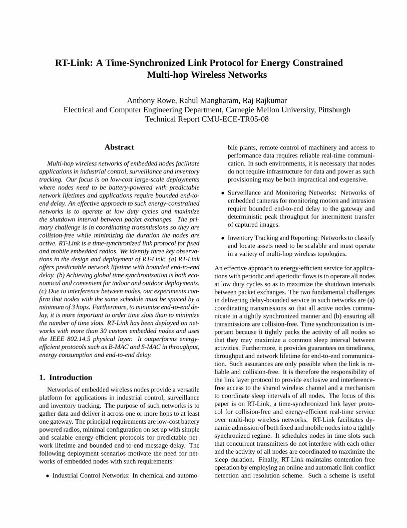
Each fixed (i.e. stationary) node has two radios which op-erate on separate channels. A low-power receiver (e.g. AM,FM, atomic clock) to detect a periodic synchronization pulseand an RF transceiver for data communication after the syncpulse is received. As shown in Figure 1, a periodic synchro-nization pulse is detected first and is followed by a finelyslotted data communication period. This period is defined asa frame and the interval between time sync pulses is definedas a cycle. The sync pulse serves as an indicator of the be-ginning of the first frame. After a frame is complete, eachnode schedules a timer to wake up just before the expectedtime of the next sync pulse and promptly switches to sleepmode. One or more frames may be scheduled within a cy-cle. Each frame is divided into two regimes of time synchro-nized operation: (a) a series of Scheduled Slots (SS) withinwhich nodes are assigned specific transmit and receive timeslots and (b) a series of Unscheduled or Contention Slots(CS) where nodes, which are not assigned slots in the SS,select a transmit slot at random. Nodes operating in SS areprovided timeliness guarantees as they are granted exclusiveaccess of the shared channel and hence enjoy the privilegeof interference-free and hence collision-free communication.Fixed nodes that have not yet been assigned a time slot in SScontinue to operate in CS and are subject to a finite probabil-ity of packet collision. We assume all nodes are aware of thefixed number of slots within the SS and CS. The methods forassigning collision-free time slots are described in Section 4.
3.2. Node Types and Packet Types
RT-Link supports both fixed and mobile nodes. Only fixednodes have a sync pulse receiver in addition to the RF datatransceiver and are able to operate within SS. Fixed nodesmaintain time synchronization by the global sync pulse andmay be assigned specific transmit and receive time slots inthe interval following the sync pulse. On the other hand, mo-bile nodes are not assigned specific scheduled time slots astheir neighbors may change frequently and therefore operate
Time-sync CycleSync Pulse Frame
Scheduled Slots Contention Slots
Figure 1. RT-Link time slot allocation with out-of-band
synchronization pulses
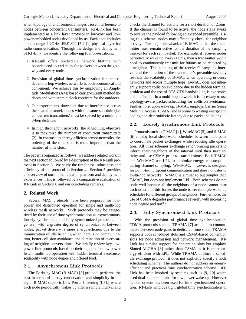
solely in CS. Mobile nodes obtain time synchronization bylistening to neighbors operating in SS. Upon detecting onesuch packet, the mobile node is informed of the current slotnumber and determines the start of the CS. It then randomlyselects a transmit slot in the CS. Only nodes operating in theSS are permitted to route data to and from the gateway. Mo-bile nodes, typically broadcast data to the gateway via oneor more fixed nodes. We now describe the six packet typesshown in Figure 2 required for basic network operation.
1. RT-Link Packet HeaderEvery packet includes the common link layer header.The common header, as shown in Figure 2(a), contains16-bit Medium Access Control (MAC) addresses of thesource, destination and current forwarding node. Asfixed nodes operate either in the SS or CS, each packetis tagged explicitly with the transmit slot number. Forexample, in our network deployment, a cycle contains32 slots including 24 (i.e. slots 0 to 23) slots within theSS and 8 slots within the CS. As guaranteed service isprovided only to nodes assigned explicit slots within theSS, only these nodes are entitled to receive an acknowl-edgement. The receiver operating within SS implicitlyacknowledges all packets received by setting a bit maskmapping the slots within which the packets were re-ceived. This provides an efficient mechanism to identifyand acknowledge transmitters operating within the SS.Mobile nodes and nodes operating within the CS, onlytransmit broadcast packets destined for the gateway andare hence never acknowledged.
2. HELLO PacketThe HELLO broadcast packet, as shown in Figure 2(b),advertises a node’s list of neighbors. This packet servesas a keep-alive packet to inform neighbors of one’s con-tinued presence and also informs the gateway of thenetwork topology. A node is considered a neighbor aslong as at least one HELLO message is received from itwithin the past k (e.g. 5) cycles.
3. SCHEDULE PacketWhen the gateway receives multiple HELLO packetsfrom a node and is satisfied about the stability of a
3
Carnegie Mellon University Department of Electrical and Computer Engineering Technical Report August 2005
a) Packet Header
c) Schedule Packet
b) Hello Packet
Magic Src MAC
1 1 1 11
DST MAC
1
TypePriority
Last Hop Slot #
Implicit ACK Mask TTL Retry # Pkts
1 2 2 2 1
114 1 1 1
12 SCHEDHeader Offset# Segs4
TX Mask RX Mask2
TX0 MAC Chan TXn MAC Chan. . .
4
1 2 1
Header 1 HELLO1 1 1
Src MAC2
# Segs1
Neighbor MAC2
. . .
d) Data Packet
Header 3-10 DATA1 1 1
Application Defined Data2
Size1
e) Route Packet
f) Error Packet
Header 12 ERROR1 1 1
Action1
Header 11 ROUTE1 1 1
Target MAC2
# Segs1
Dst MAC2
Next Hop2
. . .
Figure 2. Six packet types required for basic operation.
node’s neighborhood, it sends a unicast SCHEDULEpacket Figure 2(c) to the node with its unique slot num-bers. A node may be assigned one or more slots de-pending on a higher-level attribute such as applicationbandwidth requirements. The gateway executes a nodecoloring algorithm to determine the schedule for allknown nodes in the network such that concurrently ac-tive nodes do not interfere with each other. The nodescheduling algorithm is a network layer service and isout of the scope of this paper. However, in section 4 and5 we provide insights and describe a basic algorithm forleaf to gateway tree data collection.
A node’s schedule is described by transmit and receivebit-masks. A node is active in only those slots set ineach mask. The radio is turned off in all other slots.This enables a node to avoid listening to neighboringnodes through which no common flow is routed. In ourimplementation, we use 32-bit masks for transmit andreceive schedules.
4. DATA, ROUTE and ERROR PacketsThe DATA packet (Figure 2(d)) can contain a maximumof 100 bytes of data as the maximum size of an IEEE802.15.4 packet is 128 bytes. DATA packets supportpacket aggregation and forward aggregated data withthe sender’s address. The ROUTE packet Figure 2(e) issent to a node via unicast from the gateway to explicitly
set routes. We only provide primitive support for sourcerouting as the focus is on link communication. The ER-ROR packet (Figure 2(f)) is sent to neighbors when aconflict, due to overlapping time slots among neighbors,is detected. A node experiencing the conflict informs itsneighbors and the gateway of the error and may chooseto relinquish its slots. A node relinquishing a slot needsto restart the association procedure (described below) torequest one or more scheduled slots from the gateway.The ERROR packet informs the gateway of a schedul-ing conflict. Each packet is assigned a priority, whichmay be based on the last-hop address or packet type.When more packets have accumulated at a node thanits available buffer space, packets are dropped in the as-cending order of their priority. Packet priorities are use-ful in aggregation and the highest priority among theaggregated packets is assigned to the entire forwardedpacket.
3.3. Network Operation Procedures
Given the general slot structure, we now describe the rulesa node follows upon association, scheduled operation, duringslot assignment conflicts and disassociation.
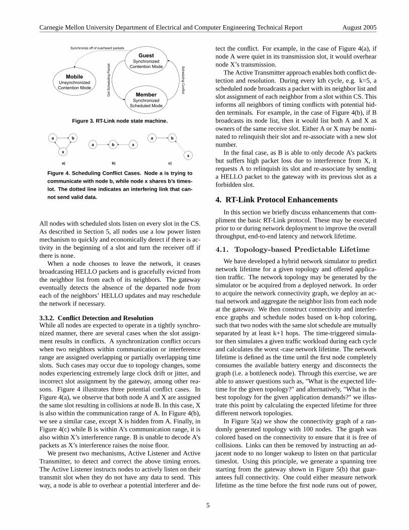
3.3.1. Network Association and DisassociationRT-Link operates on a simple 3-state state machine as shownin Figure 3. In general, nodes operating in the CS are con-sidered Guests, while nodes with scheduled slots are consid-ered Members of the network. A fixed node that is currentlya Guest becomes a Member once it is assigned one or moreslots in the SS. On the other hand, mobile nodes are neverassigned a scheduled slot and are considered Guests for thelifetime of their operation.
When a fixed node is powered on, it is first initialized asa Guest and operates in the CS. It initially keeps its syncradio receiver on until it receives a sync pulse. Followingthis, it waits for a set number of slots (spanning the SS) andthen randomly selects a slot among the CS to send a HELLOmessage with its node ID. This message is then forwardedvia flooding to the gateway and the node is eventually sched-uled a slot in the SS. In a bootstrapping manner, Guest nodescloser to the gateway should be scheduled first in order to al-low faster delivery of scheduling packets further away fromthe gateway.
During normal operation, Members and Guest wake upbefore the expected instance of the sync pulse and operate inthe SS and CS. On the other hand, when a mobile node needsto transmit, it first stays on until it overhears a neighbor op-erate in its SS. The mobile node achieves synchronization byobserving the Member’s slot number and computes the timeuntil the start of the CS. It then randomly selects a slot inthe CS and transmits. The mobile node remains silent untila Member is identified. During normal operation, all nodestransmit on their assigned slots within the SS, and turn ontheir receiver during the receive slots from each neighbor.
4
Carnegie Mellon University Department of Electrical and Computer Engineering Technical Report August 2005
GuestSynchronized
Contention Mode
MemberSynchronized
Scheduled Mode
MobileUnsynchronizedContention Mode
Scheduling Conflict
Got
Sch
edul
ing
Pac
ket
Synchronize off of overheard packets
Figure 3. RT-Link node state machine.
ba
x
ba xba
x
a) b) c)
Figure 4. Scheduling Conflict Cases. Node a is trying to
communicate with node b, while node x shares b’s times-
lot. The dotted line indicates an interfering link that can-
not send valid data.
All nodes with scheduled slots listen on every slot in the CS.As described in Section 5, all nodes use a low power listenmechanism to quickly and economically detect if there is ac-tivity in the beginning of a slot and turn the receiver off ifthere is none.
When a node chooses to leave the network, it ceasesbroadcasting HELLO packets and is gracefully evicted fromthe neighbor list from each of its neighbors. The gatewayeventually detects the absence of the departed node fromeach of the neighbors’ HELLO updates and may reschedulethe network if necessary.
3.3.2. Conflict Detection and ResolutionWhile all nodes are expected to operate in a tightly synchro-nized manner, there are several cases when the slot assign-ment results in conflicts. A synchronization conflict occurswhen two neighbors within communication or interferencerange are assigned overlapping or partially overlapping timeslots. Such cases may occur due to topology changes, somenodes experiencing extremely large clock drift or jitter, andincorrect slot assignment by the gateway, among other rea-sons. Figure 4 illustrates three potential conflict cases. InFigure 4(a), we observe that both node A and X are assignedthe same slot resulting in collisions at node B. In this case, Xis also within the communication range of A. In Figure 4(b),we see a similar case, except X is hidden from A. Finally, inFigure 4(c) while B is within A’s communication range, it isalso within X’s interference range. B is unable to decode A’spackets as X’s interference raises the noise floor.
We present two mechanisms, Active Listener and ActiveTransmitter, to detect and correct the above timing errors.The Active Listener instructs nodes to actively listen on theirtransmit slot when they do not have any data to send. Thisway, a node is able to overhear a potential interferer and de-
tect the conflict. For example, in the case of Figure 4(a), ifnode A were quiet in its transmission slot, it would overhearnode X’s transmission.
The Active Transmitter approach enables both conflict de-tection and resolution. During every kth cycle, e.g. k=5, ascheduled node broadcasts a packet with its neighbor list andslot assignment of each neighbor from a slot within CS. Thisinforms all neighbors of timing conflicts with potential hid-den terminals. For example, in the case of Figure 4(b), if Bbroadcasts its node list, then it would list both A and X asowners of the same receive slot. Either A or X may be nomi-nated to relinquish their slot and re-associate with a new slotnumber.
In the final case, as B is able to only decode A’s packetsbut suffers high packet loss due to interference from X, itrequests A to relinquish its slot and re-associate by sendinga HELLO packet to the gateway with its previous slot as aforbidden slot.
4. RT-Link Protocol Enhancements
In this section we briefly discuss enhancements that com-pliment the basic RT-Link protocol. These may be executedprior to or during network deployment to improve the overallthroughput, end-to-end latency and network lifetime.
4.1. Topology-based Predictable Lifetime
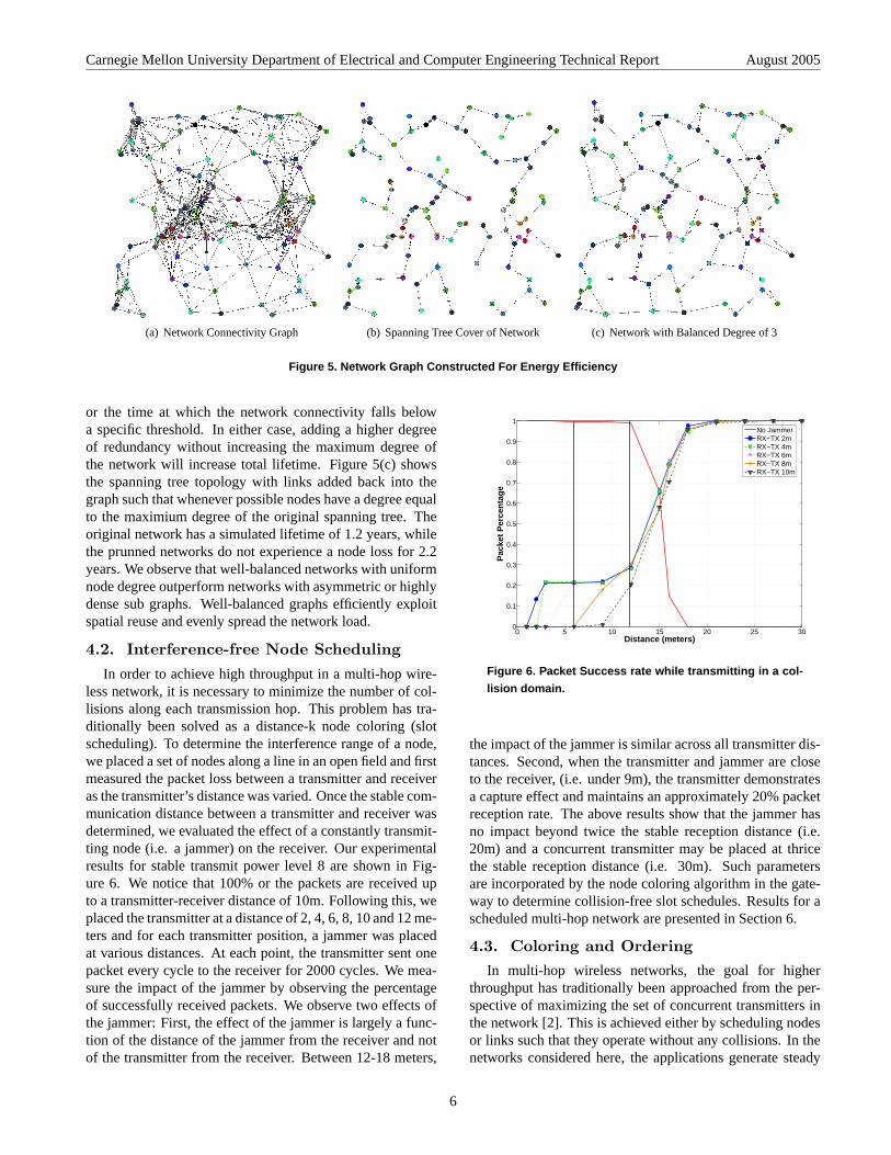
We have developed a hybrid network simulator to predictnetwork lifetime for a given topology and offered applica-tion traffic. The network topology may be generated by thesimulator or be acquired from a deployed network. In orderto acquire the network connectivity graph, we deploy an ac-tual network and aggregate the neighbor lists from each nodeat the gateway. We then construct connectivity and interfer-ence graphs and schedule nodes based on k-hop coloring,such that two nodes with the same slot schedule are mutuallyseparated by at least k+1 hops. The time-triggered simula-tor then simulates a given traffic workload during each cycleand calculates the worst -case network lifetime. The networklifetime is defined as the time until the first node completelyconsumes the available battery energy and disconnects thegraph (i.e. a bottleneck node). Through this exercise, we areable to answer questions such as, "What is the expected life-time for the given topology?" and alternatively, "What is thebest topology for the given application demands?" we illus-trate this point by calculating the expected lifetime for threedifferent network topologies.
In Figure 5(a) we show the connectivity graph of a ran-domly generated topology with 100 nodes. The graph wascolored based on the connectivity to ensure that it is free ofcollisions. Links can then be removed by instructing an ad-jacent node to no longer wakeup to listen on that particulartimeslot. Using this principle, we generate a spanning treestarting from the gateway shown in Figure 5(b) that guar-antees full connectivity. One could either measure networklifetime as the time before the first node runs out of power,
5
Carnegie Mellon University Department of Electrical and Computer Engineering Technical Report August 2005
connect
(a) Network Connectivity Graph
spanning
(b) Spanning Tree Cover of Network
d3
(c) Network with Balanced Degree of 3
Figure 5. Network Graph Constructed For Energy Efficiency
or the time at which the network connectivity falls belowa specific threshold. In either case, adding a higher degreeof redundancy without increasing the maximum degree ofthe network will increase total lifetime. Figure 5(c) showsthe spanning tree topology with links added back into thegraph such that whenever possible nodes have a degree equalto the maximium degree of the original spanning tree. Theoriginal network has a simulated lifetime of 1.2 years, whilethe prunned networks do not experience a node loss for 2.2years. We observe that well-balanced networks with uniformnode degree outperform networks with asymmetric or highlydense sub graphs. Well-balanced graphs efficiently exploitspatial reuse and evenly spread the network load.
4.2. Interference-free Node Scheduling
In order to achieve high throughput in a multi-hop wire-less network, it is necessary to minimize the number of col-lisions along each transmission hop. This problem has tra-ditionally been solved as a distance-k node coloring (slotscheduling). To determine the interference range of a node,we placed a set of nodes along a line in an open field and firstmeasured the packet loss between a transmitter and receiveras the transmitter’s distance was varied. Once the stable com-munication distance between a transmitter and receiver wasdetermined, we evaluated the effect of a constantly transmit-ting node (i.e. a jammer) on the receiver. Our experimentalresults for stable transmit power level 8 are shown in Fig-ure 6. We notice that 100% or the packets are received upto a transmitter-receiver distance of 10m. Following this, weplaced the transmitter at a distance of 2, 4, 6, 8, 10 and 12 me-ters and for each transmitter position, a jammer was placedat various distances. At each point, the transmitter sent onepacket every cycle to the receiver for 2000 cycles. We mea-sure the impact of the jammer by observing the percentageof successfully received packets. We observe two effects ofthe jammer: First, the effect of the jammer is largely a func-tion of the distance of the jammer from the receiver and notof the transmitter from the receiver. Between 12-18 meters,
0 5 10 15 20 25 300
0.1
0.2
0.3
0.4
0.5
0.6
0.7
0.8
0.9
1
Distance (meters)
Pac
ket
Per
cen
tag
e
No JammerRX−TX 2mRX−TX 4mRX−TX 6mRX−TX 8mRX−TX 10m
Figure 6. Packet Success rate while transmitting in a col-
lision domain.
the impact of the jammer is similar across all transmitter dis-tances. Second, when the transmitter and jammer are closeto the receiver, (i.e. under 9m), the transmitter demonstratesa capture effect and maintains an approximately 20% packetreception rate. The above results show that the jammer hasno impact beyond twice the stable reception distance (i.e.20m) and a concurrent transmitter may be placed at thricethe stable reception distance (i.e. 30m). Such parametersare incorporated by the node coloring algorithm in the gate-way to determine collision-free slot schedules. Results for ascheduled multi-hop network are presented in Section 6.
4.3. Coloring and OrderingIn multi-hop wireless networks, the goal for higher
throughput has traditionally been approached from the per-spective of maximizing the set of concurrent transmitters inthe network [2]. This is achieved either by scheduling nodesor links such that they operate without any collisions. In thenetworks considered here, the applications generate steady
6
Carnegie Mellon University Department of Electrical and Computer Engineering Technical Report August 2005
or low data rate flows but require low end-to-end delay.
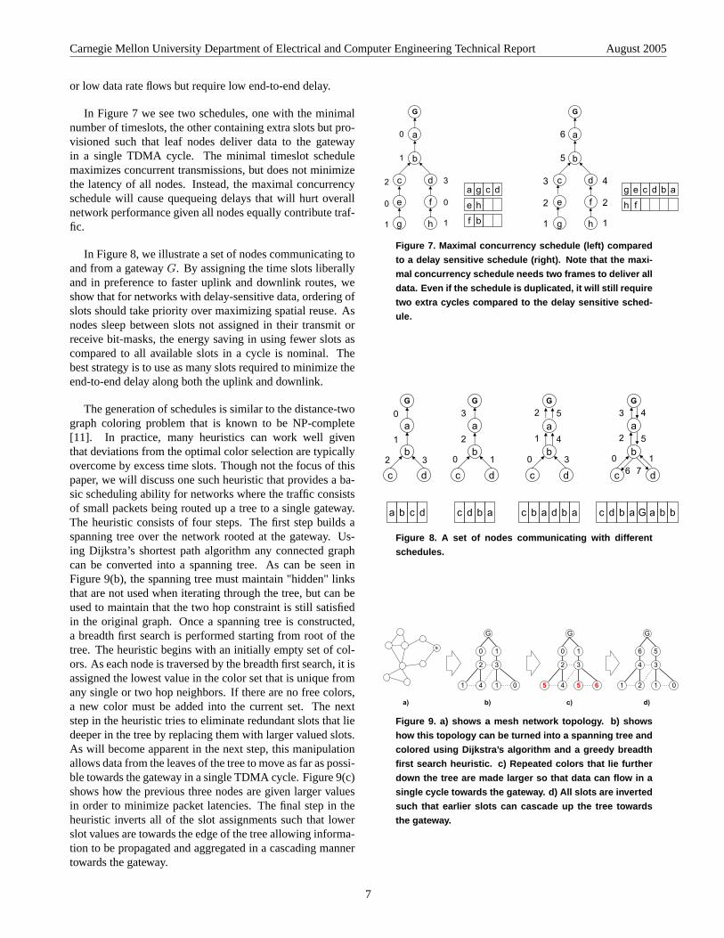
In Figure 7 we see two schedules, one with the minimalnumber of timeslots, the other containing extra slots but pro-visioned such that leaf nodes deliver data to the gatewayin a single TDMA cycle. The minimal timeslot schedulemaximizes concurrent transmissions, but does not minimizethe latency of all nodes. Instead, the maximal concurrencyschedule will cause quequeing delays that will hurt overallnetwork performance given all nodes equally contribute traf-fic.
In Figure 8, we illustrate a set of nodes communicating toand from a gatewayG. By assigning the time slots liberallyand in preference to faster uplink and downlink routes, weshow that for networks with delay-sensitive data, ordering ofslots should take priority over maximizing spatial reuse. Asnodes sleep between slots not assigned in their transmit orreceive bit-masks, the energy saving in using fewer slots ascompared to all available slots in a cycle is nominal. Thebest strategy is to use as many slots required to minimize theend-to-end delay along both the uplink and downlink.
The generation of schedules is similar to the distance-twograph coloring problem that is known to be NP-complete[11]. In practice, many heuristics can work well giventhat deviations from the optimal color selection are typicallyovercome by excess time slots. Though not the focus of thispaper, we will discuss one such heuristic that provides a ba-sic scheduling ability for networks where the traffic consistsof small packets being routed up a tree to a single gateway.The heuristic consists of four steps. The first step builds aspanning tree over the network rooted at the gateway. Us-ing Dijkstra’s shortest path algorithm any connected graphcan be converted into a spanning tree. As can be seen inFigure 9(b), the spanning tree must maintain "hidden" linksthat are not used when iterating through the tree, but can beused to maintain that the two hop constraint is still satisfiedin the original graph. Once a spanning tree is constructed,a breadth first search is performed starting from root of thetree. The heuristic begins with an initially empty set of col-ors. As each node is traversed by the breadth first search, it isassigned the lowest value in the color set that is unique fromany single or two hop neighbors. If there are no free colors,a new color must be added into the current set. The nextstep in the heuristic tries to eliminate redundant slots that liedeeper in the tree by replacing them with larger valued slots.As will become apparent in the next step, this manipulationallows data from the leaves of the tree to move as far as possi-ble towards the gateway in a single TDMA cycle. Figure 9(c)shows how the previous three nodes are given larger valuesin order to minimize packet latencies. The final step in theheuristic inverts all of the slot assignments such that lowerslot values are towards the edge of the tree allowing informa-tion to be propagated and aggregated in a cascading mannertowards the gateway.
a
b
G
c d
0
1
2 3
e f
g h
0 0
11
a
b
G
c d
6
5
3 4
e f
g h
2 2
11
a g c d
e h
f b
g e c d b a
h f
Left graph shows maximal concurrency that needs two frames to deliver all data. Even if you duplicate the schedule, you will require 2 extra cycles compared to the left graph.
Figure 7. Maximal concurrency schedule (left) compared
to a delay sensitive schedule (right). Note that the maxi-
mal concurrency schedule needs two frames to deliver all
data. Even if the schedule is duplicated, it will still require
two extra cycles compared to the delay sensitive sched-
ule.
a
b
G
c d
a
G
c d
a
G
c d
a
b
G
c d
0
1
2 3
3
2
0 1bb
2
1
0 3
4
5 3
2
0 1
5
4
6 7
a b c d c d b a c b a d b a c d b a G a b b
Figure 8. A set of nodes communicating with different
schedules.
G
1 4
2 3
1 0
10
G
a) b) c) d)
5 4
2 3
5 6
10
G
1 2
4 3
1 0
56
G
Figure 9. a) shows a mesh network topology. b) shows
how this topology can be turned into a spanning tree and
colored using Dijkstra’s algorithm and a greedy breadth
first search heuristic. c) Repeated colors that lie further
down the tree are made larger so that data can flow in a
single cycle towards the gateway. d) All slots are inverted
such that earlier slots can cascade up the tree towards
the gateway.
7
Carnegie Mellon University Department of Electrical and Computer Engineering Technical Report August 2005
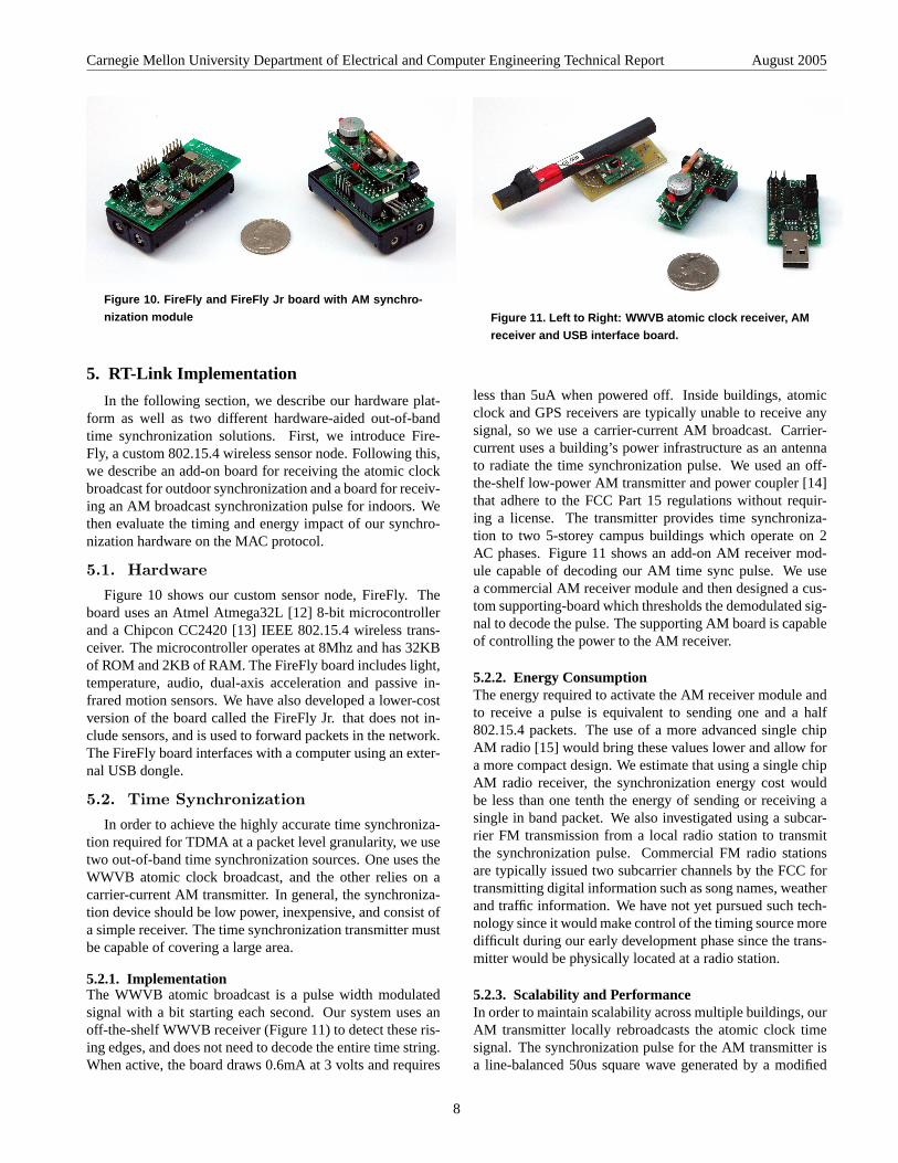
Figure 10. FireFly and FireFly Jr board with AM synchro-
nization module
5. RT-Link Implementation
In the following section, we describe our hardware plat-form as well as two different hardware-aided out-of-bandtime synchronization solutions. First, we introduce Fire-Fly, a custom 802.15.4 wireless sensor node. Following this,we describe an add-on board for receiving the atomic clockbroadcast for outdoor synchronization and a board for receiv-ing an AM broadcast synchronization pulse for indoors. Wethen evaluate the timing and energy impact of our synchro-nization hardware on the MAC protocol.
5.1. Hardware
Figure 10 shows our custom sensor node, FireFly. Theboard uses an Atmel Atmega32L [12] 8-bit microcontrollerand a Chipcon CC2420 [13] IEEE 802.15.4 wireless trans-ceiver. The microcontroller operates at 8Mhz and has 32KBof ROM and 2KB of RAM. The FireFly board includes light,temperature, audio, dual-axis acceleration and passive in-frared motion sensors. We have also developed a lower-costversion of the board called the FireFly Jr. that does not in-clude sensors, and is used to forward packets in the network.The FireFly board interfaces with a computer using an exter-nal USB dongle.
5.2. Time Synchronization
In order to achieve the highly accurate time synchroniza-tion required for TDMA at a packet level granularity, we usetwo out-of-band time synchronization sources. One uses theWWVB atomic clock broadcast, and the other relies on acarrier-current AM transmitter. In general, the synchroniza-tion device should be low power, inexpensive, and consist ofa simple receiver. The time synchronization transmitter mustbe capable of covering a large area.
5.2.1. ImplementationThe WWVB atomic broadcast is a pulse width modulatedsignal with a bit starting each second. Our system uses anoff-the-shelf WWVB receiver (Figure 11) to detect these ris-ing edges, and does not need to decode the entire time string.When active, the board draws 0.6mA at 3 volts and requires
Figure 11. Left to Right: WWVB atomic clock receiver, AM
receiver and USB interface board.
less than 5uA when powered off. Inside buildings, atomicclock and GPS receivers are typically unable to receive anysignal, so we use a carrier-current AM broadcast. Carrier-current uses a building’s power infrastructure as an antennato radiate the time synchronization pulse. We used an off-the-shelf low-power AM transmitter and power coupler [14]that adhere to the FCC Part 15 regulations without requir-ing a license. The transmitter provides time synchroniza-tion to two 5-storey campus buildings which operate on 2AC phases. Figure 11 shows an add-on AM receiver mod-ule capable of decoding our AM time sync pulse. We usea commercial AM receiver module and then designed a cus-tom supporting-board which thresholds the demodulated sig-nal to decode the pulse. The supporting AM board is capableof controlling the power to the AM receiver.
5.2.2. Energy ConsumptionThe energy required to activate the AM receiver module andto receive a pulse is equivalent to sending one and a half802.15.4 packets. The use of a more advanced single chipAM radio [15] would bring these values lower and allow fora more compact design. We estimate that using a single chipAM radio receiver, the synchronization energy cost wouldbe less than one tenth the energy of sending or receiving asingle in band packet. We also investigated using a subcar-rier FM transmission from a local radio station to transmitthe synchronization pulse. Commercial FM radio stationsare typically issued two subcarrier channels by the FCC fortransmitting digital information such as song names, weatherand traffic information. We have not yet pursued such tech-nology since it would make control of the timing source moredifficult during our early development phase since the trans-mitter would be physically located at a radio station.
5.2.3. Scalability and PerformanceIn order to maintain scalability across multiple buildings, ourAM transmitter locally rebroadcasts the atomic clock timesignal. The synchronization pulse for the AM transmitter isa line-balanced 50us square wave generated by a modified
8
Carnegie Mellon University Department of Electrical and Computer Engineering Technical Report August 2005
0 50 100 150 200 2500
1.5
2.9
4.4
5.9
7.3
8.8
10.3
11.7
13.2
Time (microseconds)
Per
cen
tag
e o
f S
ync
Pu
lses
node 0node 1node 2node 3node 4
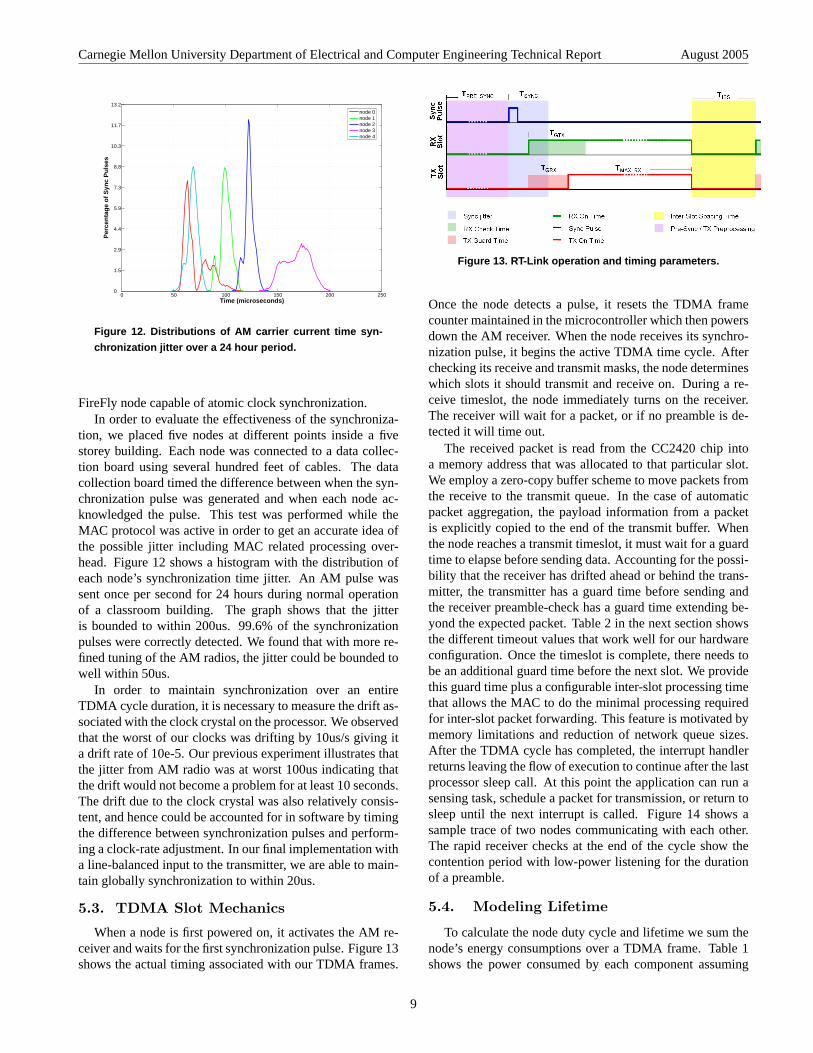
Figure 12. Distributions of AM carrier current time syn-
chronization jitter over a 24 hour period.
FireFly node capable of atomic clock synchronization.In order to evaluate the effectiveness of the synchroniza-
tion, we placed five nodes at different points inside a fivestorey building. Each node was connected to a data collec-tion board using several hundred feet of cables. The datacollection board timed the difference between when the syn-chronization pulse was generated and when each node ac-knowledged the pulse. This test was performed while theMAC protocol was active in order to get an accurate idea ofthe possible jitter including MAC related processing over-head. Figure 12 shows a histogram with the distribution ofeach node’s synchronization time jitter. An AM pulse wassent once per second for 24 hours during normal operationof a classroom building. The graph shows that the jitteris bounded to within 200us. 99.6% of the synchronizationpulses were correctly detected. We found that with more re-fined tuning of the AM radios, the jitter could be bounded towell within 50us.
In order to maintain synchronization over an entireTDMA cycle duration, it is necessary to measure the drift as-sociated with the clock crystal on the processor. We observedthat the worst of our clocks was drifting by 10us/s giving ita drift rate of 10e-5. Our previous experiment illustrates thatthe jitter from AM radio was at worst 100us indicating thatthe drift would not become a problem for at least 10 seconds.The drift due to the clock crystal was also relatively consis-tent, and hence could be accounted for in software by timingthe difference between synchronization pulses and perform-ing a clock-rate adjustment. In our final implementation witha line-balanced input to the transmitter, we are able to main-tain globally synchronization to within 20us.
5.3. TDMA Slot Mechanics
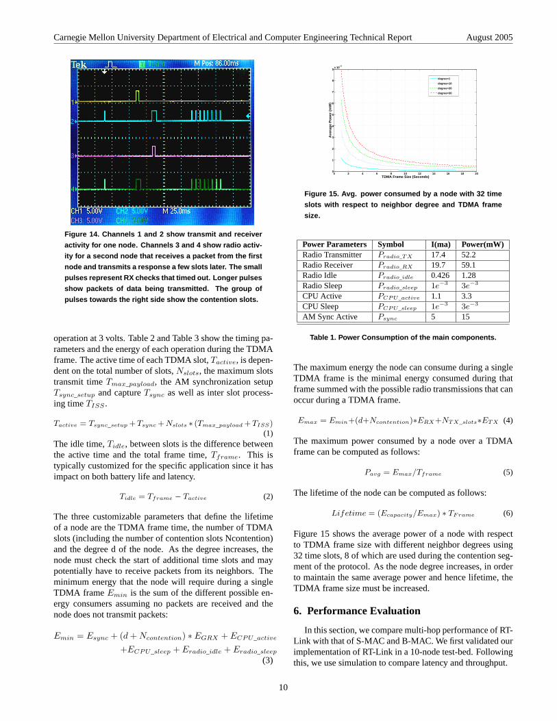
When a node is first powered on, it activates the AM re-ceiver and waits for the first synchronization pulse. Figure 13shows the actual timing associated with our TDMA frames.
Figure 13. RT-Link operation and timing parameters.
Once the node detects a pulse, it resets the TDMA framecounter maintained in the microcontroller which then powersdown the AM receiver. When the node receives its synchro-nization pulse, it begins the active TDMA time cycle. Afterchecking its receive and transmit masks, the node determineswhich slots it should transmit and receive on. During a re-ceive timeslot, the node immediately turns on the receiver.The receiver will wait for a packet, or if no preamble is de-tected it will time out.
The received packet is read from the CC2420 chip intoa memory address that was allocated to that particular slot.We employ a zero-copy buffer scheme to move packets fromthe receive to the transmit queue. In the case of automaticpacket aggregation, the payload information from a packetis explicitly copied to the end of the transmit buffer. Whenthe node reaches a transmit timeslot, it must wait for a guardtime to elapse before sending data. Accounting for the possi-bility that the receiver has drifted ahead or behind the trans-mitter, the transmitter has a guard time before sending andthe receiver preamble-check has a guard time extending be-yond the expected packet. Table 2 in the next section showsthe different timeout values that work well for our hardwareconfiguration. Once the timeslot is complete, there needs tobe an additional guard time before the next slot. We providethis guard time plus a configurable inter-slot processing timethat allows the MAC to do the minimal processing requiredfor inter-slot packet forwarding. This feature is motivated bymemory limitations and reduction of network queue sizes.After the TDMA cycle has completed, the interrupt handlerreturns leaving the flow of execution to continue after the lastprocessor sleep call. At this point the application can run asensing task, schedule a packet for transmission, or return tosleep until the next interrupt is called. Figure 14 shows asample trace of two nodes communicating with each other.The rapid receiver checks at the end of the cycle show thecontention period with low-power listening for the durationof a preamble.
5.4. Modeling Lifetime
To calculate the node duty cycle and lifetime we sum thenode’s energy consumptions over a TDMA frame. Table 1shows the power consumed by each component assuming
9
Carnegie Mellon University Department of Electrical and Computer Engineering Technical Report August 2005
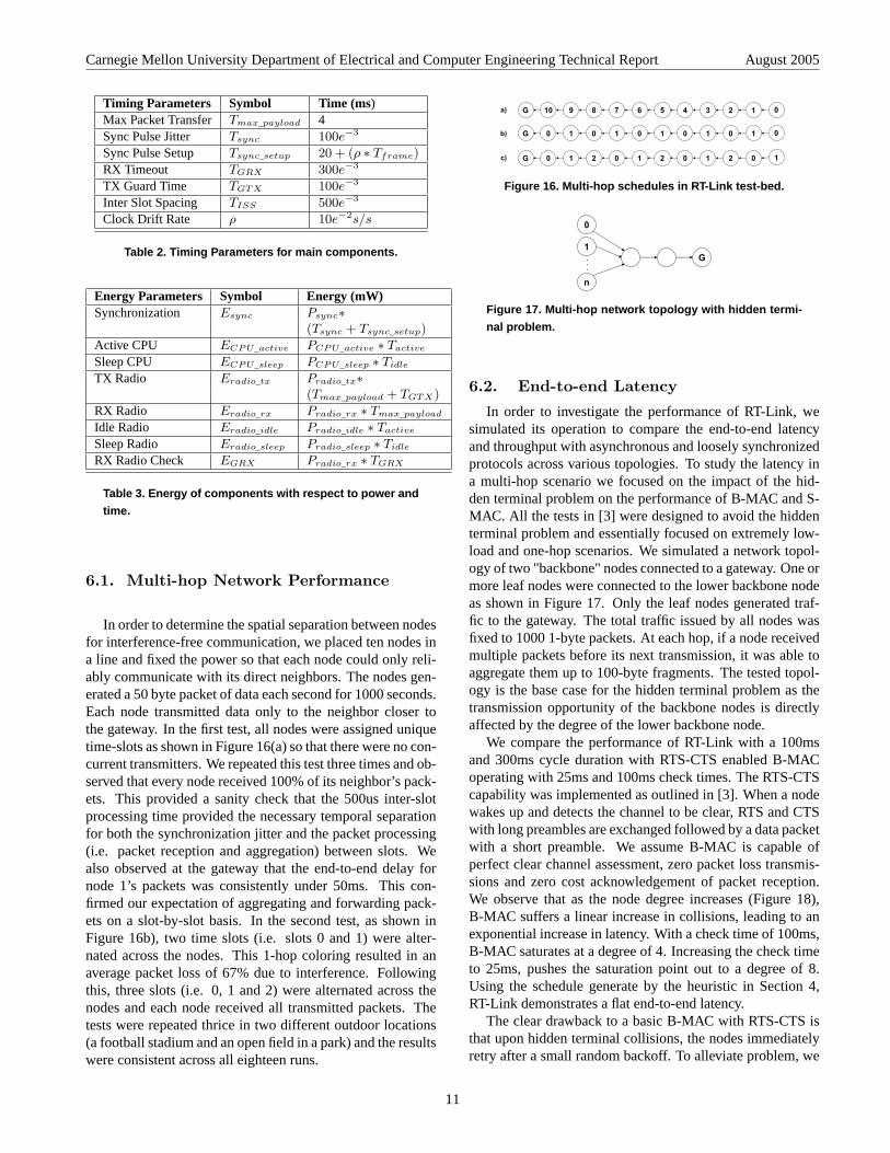
Figure 14. Channels 1 and 2 show transmit and receiver
activity for one node. Channels 3 and 4 show radio activ-
ity for a second node that receives a packet from the first
node and transmits a response a few slots later. The small
pulses represent RX checks that timed out. Longer pulses
show packets of data being transmitted. The group of
pulses towards the right side show the contention slots.
operation at 3 volts. Table 2 and Table 3 show the timing pa-rameters and the energy of each operation during the TDMAframe. The active time of each TDMA slot,Tactive, is depen-dent on the total number of slots,Nslots, the maximum slotstransmit timeTmax_payload, the AM synchronization setupTsync_setup and captureTsync as well as inter slot process-ing timeTISS .
Tactive = Tsync_setup +Tsync +Nslots ∗ (Tmax_payload +TISS)(1)
The idle time,Tidle, between slots is the difference betweenthe active time and the total frame time,Tframe. This istypically customized for the specific application since it hasimpact on both battery life and latency.
Tidle = Tframe − Tactive (2)
The three customizable parameters that define the lifetimeof a node are the TDMA frame time, the number of TDMAslots (including the number of contention slots Ncontention)and the degree d of the node. As the degree increases, thenode must check the start of additional time slots and maypotentially have to receive packets from its neighbors. Theminimum energy that the node will require during a singleTDMA frame Emin is the sum of the different possible en-ergy consumers assuming no packets are received and thenode does not transmit packets:
Emin = Esync + (d + Ncontention) ∗ EGRX + ECPU_active
+ECPU_sleep + Eradio_idle + Eradio_sleep
(3)
0 2 4 6 8 10 12 14 16 18 200
1
2
3
4
5
6
7
8
9x 10
−3
TDMA Frame Size (Seconds)
Ave
rag
e P
ow
er (
mW
)
degree=1
degree=10
degree=20
degree=30
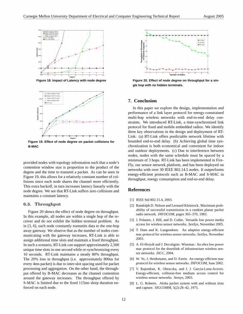
Figure 15. Avg. power consumed by a node with 32 time
slots with respect to neighbor degree and TDMA frame
size.
Power Parameters Symbol I(ma) Power(mW)Radio Transmitter Pradio_TX 17.4 52.2Radio Receiver Pradio_RX 19.7 59.1Radio Idle Pradio_idle 0.426 1.28Radio Sleep Pradio_sleep 1e−3 3e−3
CPU Active PCPU_active 1.1 3.3CPU Sleep PCPU_sleep 1e−3 3e−3
AM Sync Active Psync 5 15
Table 1. Power Consumption of the main components.
The maximum energy the node can consume during a singleTDMA frame is the minimal energy consumed during thatframe summed with the possible radio transmissions that canoccur during a TDMA frame.
Emax = Emin+(d+Ncontention)∗ERX+NTX_slots∗ETX (4)
The maximum power consumed by a node over a TDMAframe can be computed as follows:
Pavg = Emax/Tframe (5)
The lifetime of the node can be computed as follows:
Lifetime = (Ecapacity/Emax) ∗ TFrame (6)
Figure 15 shows the average power of a node with respectto TDMA frame size with different neighbor degrees using32 time slots, 8 of which are used during the contention seg-ment of the protocol. As the node degree increases, in orderto maintain the same average power and hence lifetime, theTDMA frame size must be increased.
6. Performance Evaluation
In this section, we compare multi-hop performance of RT-Link with that of S-MAC and B-MAC. We first validated ourimplementation of RT-Link in a 10-node test-bed. Followingthis, we use simulation to compare latency and throughput.
10
Carnegie Mellon University Department of Electrical and Computer Engineering Technical Report August 2005
Timing Parameters Symbol Time (ms)Max Packet Transfer Tmax_payload 4Sync Pulse Jitter Tsync 100e−3
Sync Pulse Setup Tsync_setup 20 + (ρ ∗ Tframe)
RX Timeout TGRX 300e−3
TX Guard Time TGTX 100e−3
Inter Slot Spacing TISS 500e−3
Clock Drift Rate ρ 10e−2s/s
Table 2. Timing Parameters for main components.
Energy Parameters Symbol Energy (mW)Synchronization Esync Psync∗
(Tsync + Tsync_setup)
Active CPU ECPU_active PCPU_active ∗ Tactive
Sleep CPU ECPU_sleep PCPU_sleep ∗ Tidle
TX Radio Eradio_tx Pradio_tx∗(Tmax_payload + TGTX)
RX Radio Eradio_rx Pradio_rx ∗ Tmax_payload
Idle Radio Eradio_idle Pradio_idle ∗ Tactive
Sleep Radio Eradio_sleep Pradio_sleep ∗ Tidle
RX Radio Check EGRX Pradio_rx ∗ TGRX
Table 3. Energy of components with respect to power and
time.
6.1. Multi-hop Network Performance
In order to determine the spatial separation between nodesfor interference-free communication, we placed ten nodes ina line and fixed the power so that each node could only reli-ably communicate with its direct neighbors. The nodes gen-erated a 50 byte packet of data each second for 1000 seconds.Each node transmitted data only to the neighbor closer tothe gateway. In the first test, all nodes were assigned uniquetime-slots as shown in Figure 16(a) so that there were no con-current transmitters. We repeated this test three times and ob-served that every node received 100% of its neighbor’s pack-ets. This provided a sanity check that the 500us inter-slotprocessing time provided the necessary temporal separationfor both the synchronization jitter and the packet processing(i.e. packet reception and aggregation) between slots. Wealso observed at the gateway that the end-to-end delay fornode 1’s packets was consistently under 50ms. This con-firmed our expectation of aggregating and forwarding pack-ets on a slot-by-slot basis. In the second test, as shown inFigure 16b), two time slots (i.e. slots 0 and 1) were alter-nated across the nodes. This 1-hop coloring resulted in anaverage packet loss of 67% due to interference. Followingthis, three slots (i.e. 0, 1 and 2) were alternated across thenodes and each node received all transmitted packets. Thetests were repeated thrice in two different outdoor locations(a football stadium and an open field in a park) and the resultswere consistent across all eighteen runs.
10G 9a)
b)
c)
8 7 6 5 4 3 2 1 0
0G 1 0 1 0 1 0 1 0 1 0
0G 1 2 0 1 2 0 1 2 0 1
Figure 16. Multi-hop schedules in RT-Link test-bed.
G
0
n
1...
Figure 17. Multi-hop network topology with hidden termi-
nal problem.
6.2. End-to-end Latency
In order to investigate the performance of RT-Link, wesimulated its operation to compare the end-to-end latencyand throughput with asynchronous and loosely synchronizedprotocols across various topologies. To study the latency ina multi-hop scenario we focused on the impact of the hid-den terminal problem on the performance of B-MAC and S-MAC. All the tests in [3] were designed to avoid the hiddenterminal problem and essentially focused on extremely low-load and one-hop scenarios. We simulated a network topol-ogy of two "backbone" nodes connected to a gateway. One ormore leaf nodes were connected to the lower backbone nodeas shown in Figure 17. Only the leaf nodes generated traf-fic to the gateway. The total traffic issued by all nodes wasfixed to 1000 1-byte packets. At each hop, if a node receivedmultiple packets before its next transmission, it was able toaggregate them up to 100-byte fragments. The tested topol-ogy is the base case for the hidden terminal problem as thetransmission opportunity of the backbone nodes is directlyaffected by the degree of the lower backbone node.
We compare the performance of RT-Link with a 100msand 300ms cycle duration with RTS-CTS enabled B-MACoperating with 25ms and 100ms check times. The RTS-CTScapability was implemented as outlined in [3]. When a nodewakes up and detects the channel to be clear, RTS and CTSwith long preambles are exchanged followed by a data packetwith a short preamble. We assume B-MAC is capable ofperfect clear channel assessment, zero packet loss transmis-sions and zero cost acknowledgement of packet reception.We observe that as the node degree increases (Figure 18),B-MAC suffers a linear increase in collisions, leading to anexponential increase in latency. With a check time of 100ms,B-MAC saturates at a degree of 4. Increasing the check timeto 25ms, pushes the saturation point out to a degree of 8.Using the schedule generate by the heuristic in Section 4,RT-Link demonstrates a flat end-to-end latency.
The clear drawback to a basic B-MAC with RTS-CTS isthat upon hidden terminal collisions, the nodes immediatelyretry after a small random backoff. To alleviate problem, we
11
Carnegie Mellon University Department of Electrical and Computer Engineering Technical Report August 2005
1 2 3 4 5 6 7 8 9 100
1000
2000
3000
4000
5000
6000
7000
Degree
Lat
ency
(m
s)
BMAC Adaptive 100msBMAC RTS/CTS 100msBMAC RTS/CTS 25msBMAC Adaptive 25msRT−Link 300msRT−Link 1000ms
Figure 18. Impact of Latency with node degree
1 2 3 4 5 6 7 8 9 100
2000
4000
6000
8000
10000
12000
Degree
Pac
ket
Co
llisi
on
s
BMAC Adaptive 100ms
BMAC RTS/CTS 100ms
BMAC RTS/CTS 25ms
BMAC Adaptive 25ms
RT−Link
Figure 19. Effect of node degree on packet collisions for
B-MAC
provided nodes with topology information such that a node’scontention window size is proportion to the product of thedegree and the time to transmit a packet. As can be seen inFigure 19, this allows for a relatively constant number of col-lisions since each node shares the channel more efficiently.This extra backoff, in turn increases latency linearly with thenode degree. We see that RT-Link suffers zero collisions andmaintains a constant latency.
6.3. Throughput
Figure 20 shows the effect of node degree on throughput.In this example, all nodes are within a single hop of the re-ceiver and do not exhibit the hidden terminal problem. Asin [3, 6], each node constantly transmits data to the one-hopaway gateway. We observe that as the number of nodes com-municating with the gateway increases, RT-Link is able toassign additional time slots and maintain a fixed throughput.In such a scenario, RT-Link can support approximately 2,500unique time slots in one second while re-synchronizing every10 seconds. RT-Link maintains a steady 80% throughput.The 20% loss in throughput (i.e. approximately 800us forevery 4ms packet) is due to inter-slot spacing used for packetprocessing and aggregation. On the other hand, the through-put offered by B-MAC decreases as the channel contentionaround the gateway increases. The throughput offered byS-MAC is limited due to the fixed 115ms sleep duration en-forced on each node.
2 4 6 8 10 12 14 16 18 200.1
0.2
0.3
0.4
0.5
0.6
0.7
0.8
0.9
Number of Nodes
Th
rou
gh
pu
t in
Per
cen
tag
e o
f C
han
nel
Cap
acit
y
S−MAC
B−MAC
RT-Link
Figure 20. Effect of node degree on throughput for a sin-
gle hop with no hidden terminals.
7. Conclusion
In this paper we explore the design, implementation andperformance of a link layer protocol for energy-constrainedmulti-hop wireless networks with end-to-end delay con-straints. We introduced RT-Link, a time-synchronized linkprotocol for fixed and mobile embedded radios. We identifythree key observations in the design and deployment of RT-Link: (a) RT-Link offers predictable network lifetime withbounded end-to-end delay. (b) Achieving global time syn-chronization is both economical and convenient for indoorand outdoor deployments. (c) Due to interference betweennodes, nodes with the same schedule must be spaced by aminimum of 3 hops. RT-Link has been implemented in Fire-Fly, our sensor network platform, and has been deployed onnetworks with over 30 IEEE 802.14.5 nodes. It outperformsenergy-efficient protocols such as B-MAC and S-MAC inthroughput, energy consumption and end-to-end delay.
References
[1] IEEE Std 802.15.4, 2003.
[2] Randolph D. Nelson and Leonard Kleinrock. Maximum prob-ability of successful transmission in a random planar packetradio network.INFOCOM, pages 365–370, 1983.
[3] J. Polastre, J. Hill, and D. Culler. Versatile low power mediaaccess for wireless sensor networks.SenSys, November 2005.
[4] T. Dam and K. Langendoen. An adaptive energy-efficientmac protocol for wireless sensor networks.SenSys, November2003.
[5] A. El-Hoiydi and J. Decotignie. Wisemac: An ultra low powermac protocol for the downlink of infrastructure wireless sen-sor networks.ISCC, 2004.
[6] W. Ye, J. Heidemann, and D. Estrin. An energy-efficient macprotocol for wireless sensor networks.INFOCOM, June 2002.
[7] V. Rajendran, K. Obraczka, and J. J. Garcia-Luna-Aceves.Energy-efficient, collision-free medium access control forwireless sensor networks.Sensys, 2003.
[8] L. G. Roberts. Aloha packet system with and without slotsand capture.SIGCOMM, 5(2):28–42, 1975.
12
Carnegie Mellon University Department of Electrical and Computer Engineering Technical Report August 2005
[9] C. Schurgers, V. Tsiatsis, S. Ganeriwal, and M. Srivastava.Topology management for sensor networks: Exploiting la-tency and density.MobiHoc, 2002.
[10] C. Guo, L. C. Zhong, and J. Rabaey. Low power distributedmac for ad hoc sensor radio networks.Globecom, 2001.
[11] Hari Balakrishnan et al. The distance-2 matching problemand its relationship to the mac-layer capacity of ad hoc wire-less networks. IEEE Journal on Selected Areas in Comm.,22(6):1069–1079, August 2004.
[12] Atmel corporation, atmega32 data sheet, March 2005.
[13] Chipcon inc., chipcon cc2420 data sheet, October 2003.
[14] Radio systems 30w tr-6000 am transmitter data sheet, March2001.
[15] Tea5551t 1-chip am radio philips semiconductors, October1990.
13