RSK-N, RSK-E Technical Wall shoes...
14
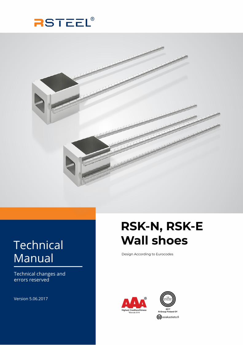
THE STRONGEST IN FINLAND Technical Manual Technical changes and errors reserved Design According to Eurocodes Version 5.06.2017 RSK-N, RSK-E Wall shoes
Transcript of RSK-N, RSK-E Technical Wall shoes...
THESTRONGESTIN FINLAND
TechnicalManualTechnical changes and errors reserved
Design According to Eurocodes
Version 5.06.2017
RSK-N, RSK-E Wall shoes
2 www.repo.eu Technical Manual - RSK-N, RSK-E Wall shoes v5.06.2017
1. DESIGN APPROACH 4
2. DIMENSIONS AND MATERIALS 5
3. FABRICATION 6
3.1 Fabrication Method 6
3.2 Quality Control 6
3.3 Shoe Markings 6
4. RESISTANCES 6
5. USER INSTRUCTIONS 7
5.1 Limits of Use 7
5.2 Design Guidance 7
5.3 Reinforcement Instructions 8
6. INSTALLATION 11
6.1 Installation of the precast wall element 12
Table of Content
3Technical Manual - RSK-N, RSK-E Wall shoes v5.06.2017www.repo.eu
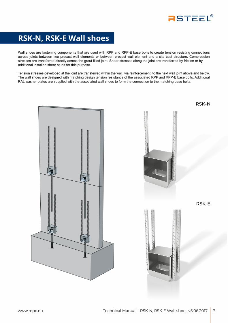
Wall shoes are fastening components that are used with RPP and RPP-E base bolts to create tension resisting connections across joints between two precast wall elements or between precast wall element and a site cast structure. Compression stresses are transferred directly across the grout filled joint. Shear stresses along the joint are transferred by friction or by additional installed shear studs for this purpose.
Tension stresses developed at the joint are transferred within the wall, via reinforcement, to the next wall joint above and below. The wall shoes are designed with matching design tension resistance of the associated RPP and RPP-E base bolts. Additional RAL washer plates are supplied with the associated wall shoes to form the connection to the matching base bolts.
RSK-N, RSK-E Wall shoes
RSK-N
RSK-E

4 www.repo.eu Technical Manual - RSK-N, RSK-E Wall shoes v5.06.2017
1. Design Approach RSK-N, RSK-E Wall shoes User Guide
1. DESIGN APPROACH Wall shoes are fastening components that are used with RPP and RPP-E base bolts to create tension resisting connections across joints between two precast wall elements or between precast wall element and a site cast structure. Compression stresses are transferred directly across the grout filled joint. Shear stresses along the joint are transferred by friction or by additional installed shear studs for this purpose.
Tension stresses developed at the joint are transferred within the wall, via reinforcement, to the next wall joint above and below. The wall shoes are designed with matching design tension resistance of the associated RPP and RPP-E base bolts. Additional RAL washer plates are supplied with the associated wall shoes to form the connection to the matching base bolts.
www.repo.eu3
Version 01/2017Technical changes and errors reserved
5Technical Manual - RSK-N, RSK-E Wall shoes v5.06.2017www.repo.eu
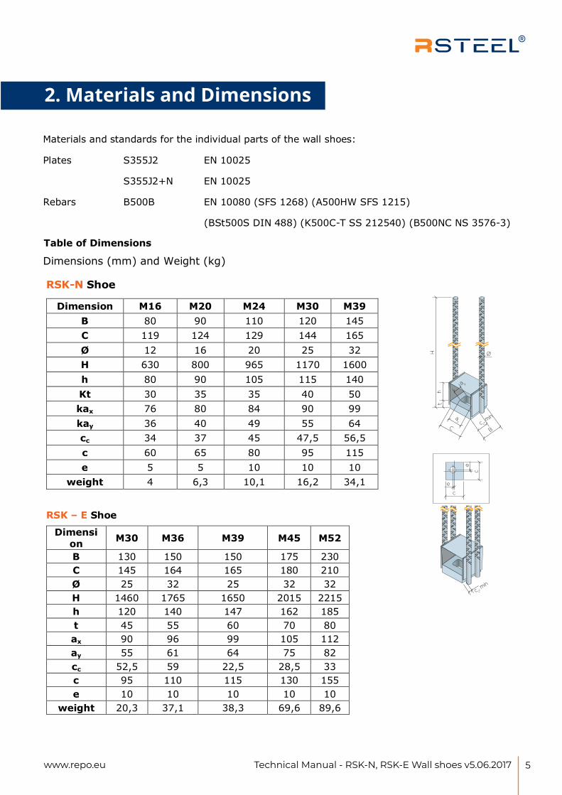
2. Materials and Dimensions2.Materials and standards for the individual parts of the wall shoes:
Plates S355J2 EN 10025
S355J2+N EN 10025
Rebars B500B EN 10080 (SFS 1268) (A500HW SFS 1215)
(BSt500S DIN 488) (K500C-T SS 212540) (B500NC NS 3576-3)
Table of Dimensions
Dimensions (mm) and Weight (kg)
Dimension M16 M20 M24 M30 M39 B 80 90 110 120 145 C 119 124 129 144 165 Ø 12 16 20 25 32 H 630 800 965 1170 1600 h 80 90 105 115 140 Kt 30 35 35 40 50 kax 76 80 84 90 99 kay 36 40 49 55 64 cc 34 37 45 47,5 56,5c 60 65 80 95 115 e 5 5 10 10 10
weight 4 6,3 10,1 16,2 34,1
Dimension M30 M36 M39 M45 M52
B 130 150 150 175 230 C 145 164 165 180 210 Ø 25 32 25 32 32 H 1460 1765 1650 2015 2215 h 120 140 147 162 185 t 45 55 60 70 80 ax 90 96 99 105 112 ay 55 61 64 75 82 cc 52,5 59 22,5 28,5 33 c 95 110 115 130 155 e 10 10 10 10 10
weight 20,3 37,1 38,3 69,6 89,6
MATERIALS AND DIMENSIONS
e
c
e
c
Bc c
, min
c c, m
in
C
ax
a y
th
H O
www.repo.eu4
Version 01/2017Technical changes and errors reserved
RSK-N Shoe
RSK – E Shoe
6 www.repo.eu Technical Manual - RSK-N, RSK-E Wall shoes v5.06.2017
4. Resistances
3. FABRICATION
Execution Standard EN 1090-2
Plates Flame cut, laser or plasma cut and mechanically cut
Rebars Mechanically cut
Welding Hand or robot MAG-welded, class C (EN ISO 5817)
In accordance with EXC 2
Surface Treatment Untreated unless agreed otherwise.
NOTE. The product shall be produced clean and dry. Light surface rusting may be present at delivery of the product. The product is to be stored in dry conditions. The product may be installed with light surface rusting, and in accordance with general requirements for reinforcement bars.
Fabrication and quality control in accordance with SFS-EN 1090-2. R-Group Oy internal quality control in accordance with ISO 9001 and ISO 14001. External quality control provided to R-Group Finland Oy: Inspecta Sertifiointi OY
R-GROUP Oy's product identifier and date
Inspecta Sertifiointi Oy's check markings
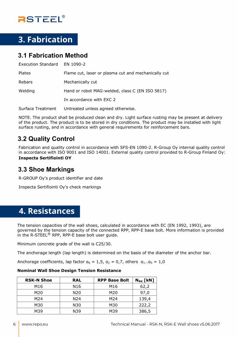
4. RESISTANCES The tension capacities of the wall shoes, calculated in accordance with EC (EN 1992, 1993), are governed by the tension capacity of the connected RPP, RPP-E base bolt. More information is provided in the R-STEEL® RPP, RPP-E base bolt user guide.
Minimum concrete grade of the wall is C25/30.
The anchorage length (lap length) is determined on the basis of the diameter of the anchor bar.
Anchorage coefficients, lap factor 6 = 1,5, 2 = 0,7, others 1 5 = 1,0
Nominal Wall Shoe Design Tension Resistance
RSK-N Shoe RAL RPP Base Bolt NRd [kN]M16 N16 M16 62,2M20 N20 M20 97,0M24 N24 M24 139,4 M30 N30 M30 222,2 M39 N39 M39 386,5
www.repo.eu5
Version 01/2017Technical changes and errors reserved
3.1 Fabrication Method
3.2 Quality Control
3.3 Shoe Markings
3. FABRICATION
Execution Standard EN 1090-2
Plates Flame cut, laser or plasma cut and mechanically cut
Rebars Mechanically cut
Welding Hand or robot MAG-welded, class C (EN ISO 5817)
In accordance with EXC 2
Surface Treatment Untreated unless agreed otherwise.
NOTE. The product shall be produced clean and dry. Light surface rusting may be present at delivery of the product. The product is to be stored in dry conditions. The product may be installed with light surface rusting, and in accordance with general requirements for reinforcement bars.
Fabrication and quality control in accordance with SFS-EN 1090-2. R-Group Oy internal quality control in accordance with ISO 9001 and ISO 14001. External quality control provided to R-Group Finland Oy: Inspecta Sertifiointi OY
R-GROUP Oy's product identifier and date
Inspecta Sertifiointi Oy's check markings
4. RESISTANCES The tension capacities of the wall shoes, calculated in accordance with EC (EN 1992, 1993), are governed by the tension capacity of the connected RPP, RPP-E base bolt. More information is provided in the R-STEEL® RPP, RPP-E base bolt user guide.
Minimum concrete grade of the wall is C25/30.
The anchorage length (lap length) is determined on the basis of the diameter of the anchor bar.
Anchorage coefficients, lap factor 6 = 1,5, 2 = 0,7, others 1 5 = 1,0
Nominal Wall Shoe Design Tension Resistance
RSK-N Shoe RAL RPP Base Bolt NRd [kN]M16 N16 M16 62,2M20 N20 M20 97,0M24 N24 M24 139,4 M30 N30 M30 222,2 M39 N39 M39 386,5
www.repo.eu5
Version 01/2017Technical changes and errors reserved
3.1 Fabrication Method
3.2 Quality Control
3.3 Shoe Markings
3. Fabrication
7Technical Manual - RSK-N, RSK-E Wall shoes v5.06.2017www.repo.eu
5. User Instructions
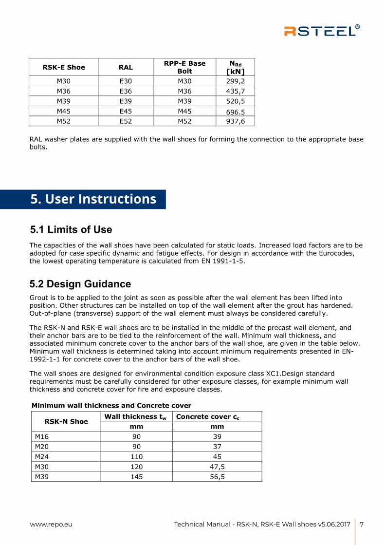
RSK-E Shoe RAL RPP-E Base Bolt
NRd[kN]
M30 E30 M30 299,2 M36 E36 M36 435,7 M39 E39 M39 520,5 M45 E45 M45 696.5 M52 E52 M52 937,6
RAL washer plates are supplied with the wall shoes for forming the connection to the appropriate base bolts.
5. USER INSTRUCTIONS
The capacities of the wall shoes have been calculated for static loads. Increased load factors are to be adopted for case specific dynamic and fatigue effects. For design in accordance with the Eurocodes, the lowest operating temperature is calculated from EN 1991-1-5.
Grout is to be applied to the joint as soon as possible after the wall element has been lifted into position. Other structures can be installed on top of the wall element after the grout has hardened. Out-of-plane (transverse) support of the wall element must always be considered carefully.
The RSK-N and RSK-E wall shoes are to be installed in the middle of the precast wall element, and their anchor bars are to be tied to the reinforcement of the wall. Minimum wall thickness, and associated minimum concrete cover to the anchor bars of the wall shoe, are given in the table below. Minimum wall thickness is determined taking into account minimum requirements presented in EN-1992-1-1 for concrete cover to the anchor bars of the wall shoe.
The wall shoes are designed for environmental condition exposure class XC1.Design standard requirements must be carefully considered for other exposure classes, for example minimum wall thickness and concrete cover for fire and exposure classes.
Minimum wall thickness and Concrete cover
RSK-N Shoe Wall thickness tw Concrete cover cc
mm mmM16 90 39 M20 90 37 M24 110 45 M30 120 47,5M39 145 56,5
www.repo.eu6
Version 01/2017Technical changes and errors reserved
5.1 Limits of Use
5.2 Design Guidance
8 www.repo.eu Technical Manual - RSK-N, RSK-E Wall shoes v5.06.2017
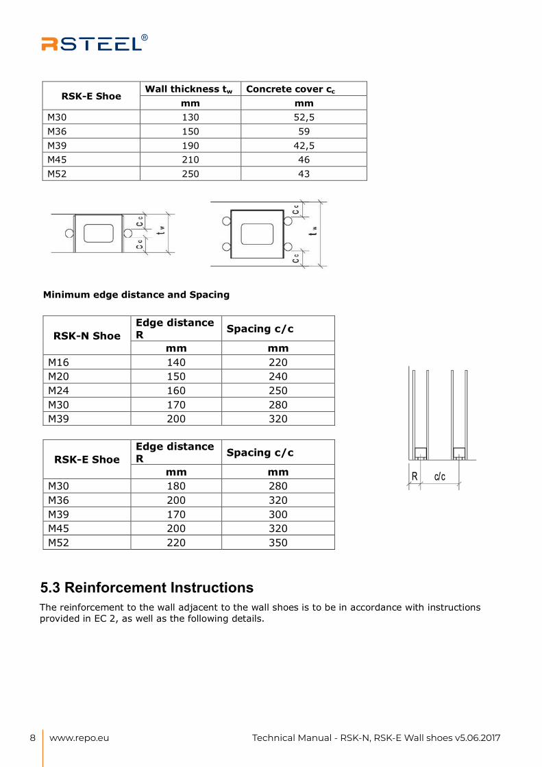
RSK-E Shoe Wall thickness tw Concrete cover cc
mm mmM30 130 52,5M36 150 59 M39 190 42,5M45 210 46 M52 250 43
Minimum edge distance and Spacing
RSK-N Shoe Edge distance R Spacing c/c
mm mm M16 140 220M20 150 240M24 160 250M30 170 280M39 200 320
RSK-E Shoe Edge distance R Spacing c/c
mm mm M30 180 280M36 200 320M39 170 300M45 200 320M52 220 350
The reinforcement to the wall adjacent to the wall shoes is to be in accordance with instructions provided in EC 2, as well as the following details.
www.repo.eu7
Version 01/2017Technical changes and errors reserved
5.3 Reinforcement Instructions

9Technical Manual - RSK-N, RSK-E Wall shoes v5.06.2017www.repo.eu
Additional Reinforcement for the RSK shoe:
www.repo.eu8
Version 01/2017Technical changes and errors reserved
Additional Reinforcement for the RSK shoe:
www.repo.eu8
Version 01/2017Technical changes and errors reserved
10 www.repo.eu Technical Manual - RSK-N, RSK-E Wall shoes v5.06.2017
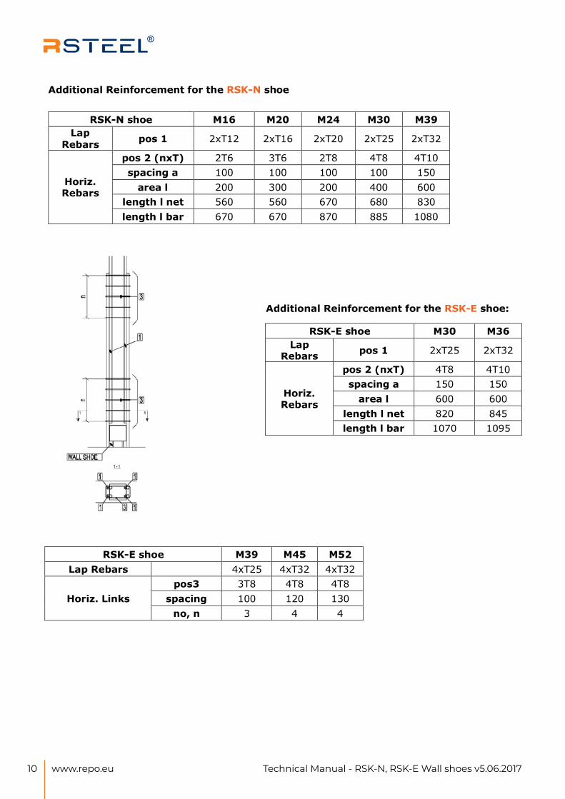
Additional Reinforcement for the RSK-N shoe
RSK-N shoe M16 M20 M24 M30 M39 Lap
Rebars pos 1 2xT12 2xT16 2xT20 2xT25 2xT32
Horiz.Rebars
pos 2 (nxT) 2T6 3T6 2T8 4T8 4T10 spacing a 100 100 100 100 150
area l 200 300 200 400 600 length l net 560 560 670 680 830 length l bar 670 670 870 885 1080
Additional Reinforcement for the RSK-E shoe:
RSK-E shoe M30 M36 Lap
Rebars pos 1 2xT25 2xT32
Horiz.Rebars
pos 2 (nxT) 4T8 4T10 spacing a 150 150
area l 600 600 length l net 820 845 length l bar 1070 1095
RSK-E shoe M39 M45 M52 Lap Rebars 4xT25 4xT32 4xT32
Horiz. Links pos3 3T8 4T8 4T8
spacing 100 120 130 no, n 3 4 4
www.repo.eu9
Version 01/2017Technical changes and errors reserved
11Technical Manual - RSK-N, RSK-E Wall shoes v5.06.2017www.repo.eu
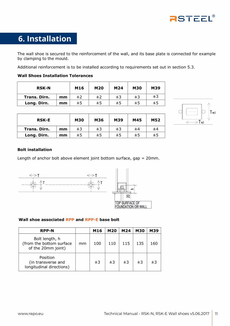
6. INSTALLATIONThe wall shoe is secured to the reinforcement of the wall, and its base plate is connected for example by clamping to the mould.
Additional reinforcement is to be installed according to requirements set out in section 5.3.
Wall Shoes Installation Tolerances
RSK-N M16 M20 M24 M30 M39
Trans. Dirn. mm ±2 ±2 ±3 ±3 ±3Long. Dirn. mm ±5 ±5 ±5 ±5 ±5
RSK-E M30 M36 M39 M45 M52
Trans. Dirn. mm ±3 ±3 ±3 ±4 ±4 Long. Dirn. mm ±5 ±5 ±5 ±5 ±5
Bolt installation
Length of anchor bolt above element joint bottom surface, gap = 20mm.
Wall shoe associated RPP and RPP-E base bolt
RPP-N M16 M20 M24 M30 M39
Bolt length, h (from the bottom surface
of the 20mm joint) mm 100 110 115 135 160
Position (in transverse and
longitudinal directions) ±3 ±3 ±3 ±3 ±3
www.repo.eu10
Version 01/2017Technical changes and errors reserved
6. Installation

12 www.repo.eu Technical Manual - RSK-N, RSK-E Wall shoes v5.06.2017
RPP-E M30 M36 M39 M45 M52
Bolt length, h (from the bottom surface
of the 20mm joint) mm 145 165 185 195 220
Position (in transverse and
longitudinal directions) ±3 ±4 ±4 ±4 ±5
Base bolt position tolerance is in accordance with the user guide for the RPP and RPP-E base bolts.
Checklist prior to casting of the wall element:
The correct shoe size and type has been installed in the mould
The positioning of the shoe is correct
Adequate tieing of the shoe into the reinforcement cage, and adequately clamped to the end plate of the mould
Casting boxes are in position
Checklist after casting of the wall element:
Shoe position is correct, and has not moved or rotated
Grouting pipe is open (if used)
Casting boxes are removed
Ensure that the shoe voids are clean i.e. no concrete or cement
The precast wall element is installed at the correct level by using packer plates. The wall element is to be temporarily support during erection, and its level and inclination checked. Before the nuts are tightened, the position of the RAL washer plate inside the wall shoe must be checked. Nuts are to be firmly tightened, for example using an impact wrench. Following tightening of the nuts, lifting connections can be disconnected and removed. Erection must follow the erection scheme that is approved by the responsible engineer.
Space required for tightening the nut with an impact wrench is verified in accordance with DIN 7444.
Once the wall element is set at the correct level and inclination, and the nuts are tightened, the base is to be grouted in accordance with the manufacturer's guidance. The grout must be of a non-shrinkage type and with strength greater than the weakest of the concrete structures that are connected together with the bolt and shoe assembly.
www.repo.eu11
Version 01/2017Technical changes and errors reserved
6.1 Installation of the precast wall element
13Technical Manual - RSK-N, RSK-E Wall shoes v5.06.2017www.repo.eu
RPP-E M30 M36 M39 M45 M52
Bolt length, h (from the bottom surface
of the 20mm joint) mm 145 165 185 195 220
Position (in transverse and
longitudinal directions) ±3 ±4 ±4 ±4 ±5
Base bolt position tolerance is in accordance with the user guide for the RPP and RPP-E base bolts.
Checklist prior to casting of the wall element:
The correct shoe size and type has been installed in the mould
The positioning of the shoe is correct
Adequate tieing of the shoe into the reinforcement cage, and adequately clamped to the end plate of the mould
Casting boxes are in position
Checklist after casting of the wall element:
Shoe position is correct, and has not moved or rotated
Grouting pipe is open (if used)
Casting boxes are removed
Ensure that the shoe voids are clean i.e. no concrete or cement
The precast wall element is installed at the correct level by using packer plates. The wall element is to be temporarily support during erection, and its level and inclination checked. Before the nuts are tightened, the position of the RAL washer plate inside the wall shoe must be checked. Nuts are to be firmly tightened, for example using an impact wrench. Following tightening of the nuts, lifting connections can be disconnected and removed. Erection must follow the erection scheme that is approved by the responsible engineer.
Space required for tightening the nut with an impact wrench is verified in accordance with DIN 7444.
Once the wall element is set at the correct level and inclination, and the nuts are tightened, the base is to be grouted in accordance with the manufacturer's guidance. The grout must be of a non-shrinkage type and with strength greater than the weakest of the concrete structures that are connected together with the bolt and shoe assembly.
www.repo.eu11
Version 01/2017Technical changes and errors reserved
6.1 Installation of the precast wall element
Notes
CREATE A NOTE
AboutR-Group is a leading provider of steel connections for precast and cast-in- situ construction around the globe.
With over three decades of our participation in huge projects, we don’t compromise on quality or customer satisfaction and we create connections for a lifetime.
Our customer-oriented service, excellent and reliable network of suppliers plus our extensive product portfolio ensure that we are able to offer professional and flexible solutions for any kind of projects.
In our operations we comply with the ISO 9001 and 14001 stan-dards
R-Group Finland OyHead Office: Katajanokankatu 6B 12, 00160 Helsinki FinlandTel : +358 (0)20 722 9420 VAT No. : FI- 2025044-5
www.repo.eu
linkedin/rsteel
R-Group Baltic OÜLõõtsa 2B11415 TALLINNMob. : +372 578 396 76
OOO R-Group18A Bolshoj pr. V.O.199034, St.Petersburg Russia Tel : +358 (0)20 722 9420 +372 578 396 76
R-Group Gulf FZE PO Box 14755Ras Al Khaymah U.A.ETel : +971 505119223 +91 840 894 45 78
© 2018 R-Group Finland OY. All rights reserved.This manual may not be reproduced in wholeor in part without the prior written approval ofR-Group Finland OY
R-Group