RPT Manual 1.12
45
The University of Reading Department of Computer Science Technical Report number RUCS/2002/TR/11/001/A Reading People Tracker Version 1.12 Reference Manual Tugdual Le Bouffant 1 Nils T Siebel 1 Stephen Cook 2 Steve Maybank 1 1 Computational Vision Group 2 Applied Software Engineering Research Group Department of Computer Science The University of Reading November 2002 1 Funding provided by the European Union, grant ADVISOR (IST-1999-11287). 2 Funding provided by the EPSRC, grant DESEL (GR/N01859).
Transcript of RPT Manual 1.12

8/8/2019 RPT Manual 1.12
http://slidepdf.com/reader/full/rpt-manual-112 1/45
The University of ReadingDepartment of Computer Science
Technical Report number RUCS/2002/TR/11/001/A
Reading People TrackerVersion 1.12
Reference Manual
Tugdual Le Bouffant1Nils T Siebel1
Stephen Cook2
Steve Maybank1
1Computational Vision Group2Applied Software Engineering Research Group
Department of Computer ScienceThe University of Reading
November 2002
1 Funding provided by the European Union, grant ADVISOR (IST-1999-11287).2 Funding provided by the EPSRC, grant DESEL (GR/N01859).

8/8/2019 RPT Manual 1.12
http://slidepdf.com/reader/full/rpt-manual-112 2/45
Tugdual Le Bouffant 1 , Nils T Siebel1, ∗, †, Stephen Cook 2 , Steve Maybank 1
Reading People Tracker version 1.12Reference Manual
AbstractThe Reading People Tracker has been maintained at the Department’sComputational Vision Group for the past 3 years. During this time,it has undergone major changes. The software has been completelyrestructured, adapted for multiple cameras and multiple trackers percamera, and integrated into the automated surveillance system ADVISOR.Part of this process has been the creation of extensive documentationfrom the source code, of which this manual is the most important part.The manual is mostly written for programmers and covers a range of issues, from architectural descriptions up to detailed documentation onthe software process now to be followed for all maintenance work on thetracker.
Keywords. Software Process Documentation, Design Patterns, Soft-ware Architecture, Reference Manual, People Tracking.
1 Computational Vision Group, 2 Applied Software Engineering Research GroupDepartment of Computer Science, The University of Reading∗Correspondence to: Nils T Siebel, Computational Vision Group, Department of Computer Science, The University of Reading, PO Box 225, Whiteknights, ReadingRG6 6AY, United Kingdom.†E-Mail: [email protected]
2

8/8/2019 RPT Manual 1.12
http://slidepdf.com/reader/full/rpt-manual-112 3/45
Contents
Contents 4
1 Introduction 61.1 History . . . . . . . . . . . . . . . . . . . . . . . . . . . . . . . . . . . 61.2 The Need to Redesign the Code . . . . . . . . . . . . . . . . . . . . . 61.3 Contributions . . . . . . . . . . . . . . . . . . . . . . . . . . . . . . . 8
2 System Architecture: Overview 92.1 Static Organisation . . . . . . . . . . . . . . . . . . . . . . . . . . . . 9
2.1.1 Domain Model . . . . . . . . . . . . . . . . . . . . . . . . . . 92.1.2 Class Diagram . . . . . . . . . . . . . . . . . . . . . . . . . . . 10
2.2 Dynamic Organisation . . . . . . . . . . . . . . . . . . . . . . . . . . 10
2.2.1 Use Case Figure 2: Standalone . . . . . . . . . . . . . . . . . 102.2.2 Use Case Figure 3: ADVISOR . . . . . . . . . . . . . . . . . . 122.2.3 Robustness Diagram . . . . . . . . . . . . . . . . . . . . . . . 142.2.4 Sequence Diagram . . . . . . . . . . . . . . . . . . . . . . . . 15
3 Design Patterns 153.1 Requirements for the People Tracker . . . . . . . . . . . . . . . . . . 153.2 The way to use Classes . . . . . . . . . . . . . . . . . . . . . . . . . . 16
3.2.1 Architectural Pattern . . . . . . . . . . . . . . . . . . . . . . . 163.2.2 Idioms and Rules . . . . . . . . . . . . . . . . . . . . . . . . . 17
3.3 Patterns Implementation . . . . . . . . . . . . . . . . . . . . . . . . . 223.3.1 Inputs . . . . . . . . . . . . . . . . . . . . . . . . . . . . . . . 223.3.2 ReadingPeopleTracker . . . . . . . . . . . . . . . . . . . . . . 243.3.3 PeopleTracker . . . . . . . . . . . . . . . . . . . . . . . . . . . 253.3.4 Camera . . . . . . . . . . . . . . . . . . . . . . . . . . . . . . 263.3.5 Tracking . . . . . . . . . . . . . . . . . . . . . . . . . . . . . . 283.3.6 Results . . . . . . . . . . . . . . . . . . . . . . . . . . . . . . . 29
4 How to Create or Design and Implement... 304.1 A New Shape Model . . . . . . . . . . . . . . . . . . . . . . . . . . . 304.2 A New ImageSource . . . . . . . . . . . . . . . . . . . . . . . . . . . 31
4.3 A New Tracker or Detector Module . . . . . . . . . . . . . . . . . . . 314.3.1 Inputs and Results . . . . . . . . . . . . . . . . . . . . . . . . 314.3.2 Frame Processing . . . . . . . . . . . . . . . . . . . . . . . . . 324.3.3 Detection . . . . . . . . . . . . . . . . . . . . . . . . . . . . . 324.3.4 Tracking . . . . . . . . . . . . . . . . . . . . . . . . . . . . . . 334.3.5 Base Tracker . . . . . . . . . . . . . . . . . . . . . . . . . . . 33
4.4 Actual Conguration And Algorithm Of The Tracking Task . . . . . 33
5 Conguration Files Organisation 34
6 Libraries Description 35
4

8/8/2019 RPT Manual 1.12
http://slidepdf.com/reader/full/rpt-manual-112 4/45
7 Reverse engineering of the RPT code using Rational Rose’s C++Analyser Module 407.1 Rational Rose C++ Analyser . . . . . . . . . . . . . . . . . . . . . . . 407.2 Error Messages . . . . . . . . . . . . . . . . . . . . . . . . . . . . . . 43
References 46
5

8/8/2019 RPT Manual 1.12
http://slidepdf.com/reader/full/rpt-manual-112 5/45
1 Introduction
This document gives an overview of the Reading People Tracker in the Computa-tional Vision Group, Department of Computer Science, at the University of Reading.The aim of this documentation is to provide information in order to help future de-velopment of the People Tracker. Most of the material presented in this section andsection 2 was taken from [1].
1.1 History
The original People Tracker was written by Adam Baumberg at the University of Leeds in 1993–1995 using C++ running under IRIX on an sgi computer. It was aresearch and development system within the VIEWS project and a proof of conceptfor a PhD thesis [2]. The main focus during development was on functionality and
experimental features which represented the state-of-the-art in people tracking atthat time. Only a few software design techniques were deployed during the initialcode development. The only documentation generated was a short manual on howto write a program using the People Tracking module.
In 1995–1998 the People Tracker was used in a collaboration between the Uni-versities of Leeds and Reading in the IMV project. The software was changed atthe University of Reading to inter-operate with a vehicle tracker which ran on aSun / Solaris platform [3]. Only little functionality was changed and added duringthis time and no new documentation was created.
Starting in 2000, the People Tracker has been changed for its use within the
ADVISORsystem shown in Figure 8. This new application required a number of major changes on different levels.
1.2 The Need to Redesign the Code
The planned use of the People Tracker within the ADVISORSystem carried manyrequirements that could not be met by the original implementation. Most of thenew requirements arose from the fact that the People Tracker would now have to bepart of an integrated system, while earlier it was standalone. The use of the PeopleTracker within the ADVISORsystem also meant moving it “from the lab to the realworld” which necessitated many changes. Figure 8 shows how the People Trackingmodule is connected to the other components of the ADVISORsystem.
The new requirements for the People Tracker were:
• The People Tracker has to be fully integrated within the ADVISORsystem.
• It has to run multiple trackers, for video input from multiple cameras (originalsoftware: one tracker, one camera input).
• The ADVISORsystem requires the People Tracker to operate in realtime. Previ-ously, the People Tracker read video images from hard disk which meant therewere no realtime requirements.
6

8/8/2019 RPT Manual 1.12
http://slidepdf.com/reader/full/rpt-manual-112 6/45
• Within ADVISOR, the People Tracker has to run autonomously once it has beenset up, without requiring input from an operator and without the possibilityto write any message to screen or display any image.
• The software has to be ported from sgi to a standard PC running GNU/Linuxto make economical system integration feasible.
The status of the existing People Tracker was evaluated in relation to the new require-ments. It was observed that the system had signicant deciencies which hinderedthe implementation of the required new functionality:
• The heavy use of global variables and functions meant that multiple camerascould not be used.
• Except a few pages of operating manual, no other documentation was avail-able. As a result, changing the software to add functionality, etc. requireddisproportionate amount of effort.
• There were very little comments in the source code which made it difficult toread and understand.
• The names of some of the classes and methods were misleading.
In the years 2000 and 2001, the People Tracker was reverse-engineered and re-engineered. The aim of the reverse engineering/re-engineering step was:
• to understand the program and the design,
• to nd and correct design aws and
• to recover all the software engineering artefacts like the requirements and thedesign documents.
From the source code, the class diagram was obtained by using the tool Rational Rose2000e [4]. The analysis of the class diagram revealed that many class names did notreect the inheritance hierarchy, a number of classes were found to be redundant,and many classes had duplicated functionality. The following correctional steps wereperformed:
• Redundant classes were removed.
• Global variables and functions were eliminated and their functionality dis-tributed into both existing and new classes. Exceptions were global helperfunctions like min() , max() etc which were extracted and moved into one C++module.
• Many refactoring techniques [ 5] were applied, such as:
7

8/8/2019 RPT Manual 1.12
http://slidepdf.com/reader/full/rpt-manual-112 7/45
– Filtering out functionality duplicated in similar classes and moving it intonewly created base classes.
– Re-distribution of functionality between classes and logical modules.
– Re-distribution of functionality between methods.• Consistent renaming of le names to reect classes dened in them.
• Meaningful names were given to classes and methods.
• The previous version of the code contained many class implementations in theheader les; they were moved to the implementation ( .cc ) les.
• Assertions [6, chap. 6] were introduced at strategic points in the existing codeand in all of the new code.
• From both static analysis and dynamic analysis [7], a requirement documentand the UML artefacts like the Use Case, component, and package level se-quence diagrams [8] were obtained. The UML diagrams have been shown inFigures 3 through 7 respectively.
In the nal step, the remaining part of the required new functionality was incorpo-rated into the re-engineered People Tracker. This includes the addition of separateprocessing threads for each video input, addressing the synchronisation and tim-ing requirements etc. A newly created master scheduler manages all processing,in order to guarantee realtime performance with multiple video inputs. This ver-
sion of the People Tracker incorporates most of the functionality needed for its usewithin ADVISORand improvements to the people tracking algorithms which makeit appropriate for the application [ 9]. The module has been validated against testdata. Currently, the nal stage of system integration is being undertaken, and thisdocument, together with a User Manual to be written, completes the documentation.
1.3 Contributions
The following people have contributed to the Reading People Tracker up to thecurrent version 1.12 of the software (dated Mar 11 2002).
1. Design / Coding
• Adam Baumberg (AMB), The University of Leeds.• Nils T Siebel (NTS), The University of Reading.• Tony Heap (AJH), The University of Leeds.• Tom Grove (TDG), The University of Reading.
2. Coding
• Daniel Ponsa Mussarra (DPM), Universidad Aut´ onoma de Barcelona.
8

8/8/2019 RPT Manual 1.12
http://slidepdf.com/reader/full/rpt-manual-112 8/45
• Philip Elliott (PTE), The University of Reading.• Remi Belin (RB), Universite de Toulon et du Var.• Tugdual Le Bouffant (TLB), The University of Reading.
3. Documentation
• Tugdual Le Bouffant (TLB), The University of Reading• Nils T Siebel (NTS), The University of Reading• Daniel Rodrıguez Garcıa (DRG), The University of Reading• Stephen Cook, The University of Reading
2 System Architecture: Overview
2.1 Static Organisation
The static organisation describes the organisation of the different parts of the codesuch as libraries and the links between them. This organisation is important tounderstand the code architecture and the use of each library in the program.
2.1.1 Domain Model
The domain model, shown in Figure 1, is the representation of the libraries usedand developed for the Reading People Tracker program. The yellow blocks representthe parts which are libraries of our own source code. The other parts are standardlibraries and include les. This diagram shows the relationship between each library,the arrows means that the library pointed is used by the the one which point: PCAlibrary will use some function from the the matrix library.
• PCA: Principal Component Analysis and shape modelling, used by the ActiveShape Tracker. PCA is used to generate the space of pedestrian outlines fromtraining examples.
• matrix: library of tools for matrix calculations.
• data: set of standard data features (skeleton, proles, human features, etc).• utils: this library is the variable conguration manager.
• tracking: this library contains all the tracker, detector and camera classes.
• imgsrc: this library deals with images format and sources.
• xml: this library deals with XML les.
9

8/8/2019 RPT Manual 1.12
http://slidepdf.com/reader/full/rpt-manual-112 9/45
Figure 1: Software Packages of the People Tracker
2.1.2 Class Diagram2.2 Dynamic Organisation
This section describes the dynamic organisation of the Reading People Tracker in 3subsections:
• Use Case Model: deals with the actions performed by the system under theactors’ interactions. Who are the users of the system (the actors), and whatare they trying to do?
• Robustness Diagram: denes the types of object from the use case model.What object are needed for each use case?
• Sequence Diagram: represents the object ow. How do the objects collaboratewithin each use case?
2.2.1 Use Case Figure 2: Standalone
Use Case Diagram
This use case shows the action sequence that actors:
• Video Database and
10

8/8/2019 RPT Manual 1.12
http://slidepdf.com/reader/full/rpt-manual-112 10/45
• Developer,
perform with the system in Standalone mode to achieve a particular goal which isthe result of the Track New People Position use case.
Figure 2: Use Cases for the People Tracker (in Standalone/Development Mode)
High Level Use Case
Use Case: Decompress JPEG Image.Actor: Video Database, Internal Motion Detection, Track New People Position.
Description: JPEG images are decompressed form the database of images whichwill be used by the Motion Detection module and the Track New People Positionmodule. This will be replicated per each video sequence from each cameras.
Use Case: Internal Motion Detector.Actor: JPEG image decompressed, Track New People Position.Description: The motion detection is done using the difference of the image withpeople moving and the background image, this will be used by the Track New Peo-ple Position module to track the motion detected. This will be replicated per camera.
Use Case: Determine Tracking Parameters.Actor: Developer, Track New People Position.Description: The developer enters some variable conguration needed by the systemto run, this will congure the variables for the Track New People Position module.This is replicated per cameras and per tracker used.
Use Case: Predict Old People Position.Actor: Track New People Position.Description: On each frame processing a prediction is done on the next position of a person tracked, this prediction is then checked and validate if correct. This willbe replicate per camera.
11

8/8/2019 RPT Manual 1.12
http://slidepdf.com/reader/full/rpt-manual-112 11/45
Use Case: Track New People Position.Actors: Decompress JPEG Image, Internal Motion Detector, Predict Old ObjectPosition, Determine Tracking Parameters and Generate Tracking Result.Description: This the Central task of the system, it generates the result of thetracking of a new person’s position. Non replicated.
Use Case: Fuse Data from Cameras.Actor: Generate Tracking Result.Description: This use case shows that all the result of each cameras are fused andsent to the Generate Tracking Results module. Non replicated.
Use Case: Generate Tracking output.Actors: Track New People Position, Output Tracking Results to Screen and FuseData from Cameras.Description: Generates the Tracking result form all the cameras. Non replicated.
Use Case: Output Tracking Result to Screen.Actor: Generate Tracking Result, Developer.Description: This use case will use the result generated by the tacking to displaythe result on screen to the Developer. Non replicated.
2.2.2 Use Case Figure 3: ADVISOR
Use Case Diagramthis use case is a sequence of actions that the following actors perform with thePeople Tracking subsystem of ADVISOR:
• the Video Capture Module (from Thales),
• the External Motion Detection Module (from INRIA) and
• the Behaviour Analysis Module (to INRIA),
The goal is to Track New People Position with Video and Motion Detection as inputs
and the result as output sent to the Behaviour Analysis.
12

8/8/2019 RPT Manual 1.12
http://slidepdf.com/reader/full/rpt-manual-112 12/45
Figure 3: Use Cases for the People Tracker (as a Subsystem of ADVISOR)
High Level Use Case
Use Case: Decode Motion Detection DataActor: External Motion Detection Module, Track New People Position.Description: Decode the XML data into data usable in the PeopleTracker program.Replicated per camera.
Use Case: Predict Old People Position.Actor: Track New People Position.Description: On each frame processing a prediction is done on the next position of
a people tracked, this prediction is then checked and validate if correct. This will bereplicate per camera.
Use Case: Track New People Position.Actors: Video Capture Module, Predict Old People Position and Decode MotionDetection Data.Description: This the Central task of the system, it generates the result of thetracking of a new people position. This will be replicated per camera.
Use Case: Fuse Data from Cameras.
Actor: Generate Tracking Results.Description: This use case shows that all the result of each cameras are fused andsent to the Generate Tracking Result module. Non replicated.
Use Case: Generate Tracking output.Actors: Track New People Position, Encode Tracking Results into XML and FuseData from Cameras outputs.Description: This use case generate the Tracking result form all the cameras.Replicated per camera.
Use Case: Encode Tracking Result into XML
13

8/8/2019 RPT Manual 1.12
http://slidepdf.com/reader/full/rpt-manual-112 13/45
Actor: Behaviour Analysis Module, Generate Tracking ResultsDescription: Result generated are encode into XML format to be transported viaEthernet to an other module which will use these result to perform the behaviouranalysis.
2.2.3 Robustness Diagram
The Robustness Analysis involves analysing each of the use cases and identifying aset of objects that will participate in the use case, then classifying those into threetypes of objects:
• Boundary object, which actors use in communicating with the system.
• Entity object, which represent a result and which will be used for externaltasks.
• Control objects, which is the action performed by the system.
Figure 4: Standalone Robustness Diagram
Figure 5: ADVISORRobustness Diagram
14

8/8/2019 RPT Manual 1.12
http://slidepdf.com/reader/full/rpt-manual-112 14/45
2.2.4 Sequence Diagram
This diagram is also named interaction diagram. It shows the ow of requests be-tween objects. Interaction modelling is the phase in which the threads that weave
objects together are built. At this stage it is possible to see how the system performsuseful behaviour. The sequence diagrams for the People Tracker have been shown inFigures 6 and 7.
Figure 6: Standalone Sequence Diagram (at a Higher Level)
3 Design Patterns
Design patterns systematically describe names, motivate, and explain a general de-sign that addresses a recurring design problem in all object-oriented systems. Theydescribe the problem, the solution, when to apply the solution, and its consequences.They also give implementation hints and examples. The solution is a general ar-rangement of objects and classes that solve the problem in a particular context.
3.1 Requirements for the People Tracker
The People Tracker has to support two modes of operation:
• Standalone mode see gure 2 section 2.2.1,
• Subsystem of ADVISORsee gure 3 section 2.2.2.
15

8/8/2019 RPT Manual 1.12
http://slidepdf.com/reader/full/rpt-manual-112 15/45
Figure 7: ADVISORSequence Diagram (at a Higher Level)
This two mode of operation are controlled at compile time using preprocessor#defines . The ADVISORmode is enabled if and only if THALES_WRAPPERis dened.Image output is disabled if NO_DISPLAYis dened, and it has to be dene in ADVISORmode.
3.2 The way to use Classes
Design patterns are divided in 2 categories: Architectural pattern, Idioms and Rules.
3.2.1 Architectural Pattern
An architectural pattern expresses a fundamental structural organisation schema forsoftware systems. It provides a set of predened subsystems, species their respon-sibilities, and includes rules and guidelines for organising the relationships betweenthem [10, p. 12].
Conceptual / Logical Architecture
People Tracking is one the six subsystem of ADVISOR. The Reading People Trackermodule has to communicate with two others, receiving information and generate theresult to be sent to an other module.
• Input: The video capture and motion detection subsystems are done by respec-tively Thales and INRIA. These subsystems send to the People Tracker XMLles containing the images:
1. Motion image (foreground with blob)
16

8/8/2019 RPT Manual 1.12
http://slidepdf.com/reader/full/rpt-manual-112 16/45
2. Video image3. Background image
• Output: the result of the People Tracking is sent to the behaviour analysissubsystem done by INRIA. The result sent by People Tracker is an XML lecontaining the information on tracked people.
Figure 8: The ADVISORSystem with its 6 Subsystems
Physical Architecture
Figure 8 shows the overall system layout, with individual subsystems for tracking,
detection and analysis of events, storage and human-computer interface. Each of these subsystems is implemented to run in realtime on off-the-shelf PC hardware,with the ability to process input from a number of cameras simultaneously. Theconnections between the different subsystems are realised by Ethernet. As we havealready seen, this subsystem has one input and one output.
3.2.2 Idioms and Rules
An idiom is a low-level pattern specic to a programming language. An idiom de-scribes how to implement particular aspects of components or the relationships be-tween them using the features of the given language [ 10, p 14].
Several idioms are used in our code. Some of which are very important. Theyare listed and they have to be followed for any change of the source code. Some of them are directly linked to the programming language rules [ 11].
Naming Conventions
• Class names and their associated les have to be written as uppercase forthe rst letter of each component, e.g. ActiveShapeTracker . Underscores ’ ’are not used in class names. Two different lename extensions are used forC++ les header declaration ( .h ) and implementation denition ( .cc ). Thefollowing examples demonstrate the way to name things:
17

8/8/2019 RPT Manual 1.12
http://slidepdf.com/reader/full/rpt-manual-112 17/45
– ClassName
– associated les ClassName.h for the class declaration and ClassName.ccfor its implementation.
– method_name() (within a class)– a_local_variable (global variables are forbidden)
– get_a_variable() , “Accessor”
– set_a_variable() , “Modier”
• All comments are to be written in plain British English.
• Use the C++-style // for comments, not the C-style /* */ .
• Standard use of 8 character tabulation.
• All main() programs and test cases have to be situated in the progs/ subdi-rectory.
Include Files
• Use the directive #include "filename.h" for user-prepared include les(i.e. those which are part of our own code).
• Use the directive #include <filename.h> for include les from system li-braries.
• Every include le must contain a mechanism that prevents multiple inclusions of the le. The dened “guard denition” has to be written in uppercaseletters, it has to begin and nish with 2 underscores, and each term has tobe separated by one underscore. For example, at beginning of the include lecalled | ActiveShapeTracker.h— you will see
#ifndef __ACTIVE_SHAPE_TRACKER_H__#define __ACTIVE_SHAPE_TRACKER_H__
This exact format has to be adopted.
Functions and Variables
• Global variables and functions must be avoided; they almost always violate theprinciple of encapsulation. Instead use static member functions of classes, e.g.there is a PeopleTracker::create_new_id() static member function to createa new, globally unique id from any thread.
18

8/8/2019 RPT Manual 1.12
http://slidepdf.com/reader/full/rpt-manual-112 18/45
• Minimal use of #define macros, use inline functions instead. The normal rea-son for declaring a function inline is to improve performance. Small functions,such as access functions, which return the value of a member of the class andso-called forwarding functions which invoke another function should normallybe inline .
• The difference between int &a (or int *a ) and int& a is that the rst oneseems to associate the &or (or *, for that matter) with the type, and the secondone with the variable. From the compiler point of view there is no differencebetween them. Associating the & or * with the type name reects the desireof some programmers for C++ to contain a separate pointer type. However,neither the & nor the * is distributive over a list of variables. See for exampleint *a,b; Here b is declared as an integer (not a pointer to an integer), onlya is a pointer to an integer.
For these reasons, never write int& a , only int &a .
• Assertions, using the assert(expression) macro (dened by the ISO C in-clude le <assert.h> ), should be used in order to nd programming errorsat an early stage. Assertions are generally used to help verify that a pro-gram is operating correctly, with expression being devised in such a way thatit evaluates to true only when there is no error in the program. For exam-ple, the constructor to the Image class has a parameter for the image width.assert (the_width > 0); is used to make sure that the given width is valid,because if it is not, something else has gone wrong in the past. Instead of
trying to continue, the error should be found. This is done with the help of the mentioned assertion. See [6, chap. 6] for further reading.
• The inline function:
– Access functions are to be inline ,
– Forwarding functions are to be inline ,
The normal reason for declaring a function inline is to improve the perfor-mance of your program. Correct use of inline functions may also lead toreduced size of code.
• A virtual function is a member function that is declared within a base classand redened by a derived class. In essence, virtual function implement the“one interface, multiple methods” philosophy that underlies polymorphism.The virtual function within the base class denes the form of the interface tothat function.
• The use of unsigned type: the unsigned type is used to avoid inconsistency anerror generation. It is widely use in the matrix library (e.g., you cannot specifya negative number of columns for a matrix calculation). Always use unsignedfor variables which cannot reasonably have negative values.
19

8/8/2019 RPT Manual 1.12
http://slidepdf.com/reader/full/rpt-manual-112 19/45
• The use of const : this identier has to be used when you want to keep the valueof a variable. It makes it impossible to overwrite its value. A member functionthat does not affect the state of the an object is to be declared const . Alltrackers or detectors have to be derived from BaseTracker using pure virtualmethods.
• All types used by more than one class have to be dened intracker_defines_type_and_helpers , for instance: the image source type.
Classes
• Denitions of classes that are only accessed via pointers (*) or references (&)shall not be included as include les. Instead, use forward declarations, forexample, in ActiveShapeTracker.h one can nd:
class Image;class ActiveModel;...
in ActiveShapeTracker.cc these forward declared classes are dened by in-cluding the respective header les:
#include "Image.h"#include "ActiveModel.h"
...
• Use base classes where useful and possible. A base class is a class from whichno object is created; it is only used as a base class for the derivation of otherclasses. For example see BaseTracker class
• public, protected, private sections of a class are to be declared in thatorder. By placing the public section rst, everything that is of interest to auser is gathered in the beginning of the class denition. The protected sectionmay be of interest to designers when considering inheriting from the class. The
private section contains details that should have the least general interest.– public members of a class are member data and functions which are
everywhere accessible by specifying an instance of the class and the name.– protected members are variables or functions which are accessible by
specifying the name within member functions of derived classes.– private members are variables or functions which are only accessible
inside the class.
• A friend function has access to all private and protected members of theclass for which it is a friend.
20
8/8/2019 RPT Manual 1.12
http://slidepdf.com/reader/full/rpt-manual-112 20/45
Use and Update the Source Code
The Reading People Tracker source code is shared between several developers. Toaccess the source code it is necessary to use CVS (Concurrent Version System) which
permits to a group of people to work at the same time on the same code. There is aMaster Repository of the Source code you can use it in three ways:
• CVS checkout source_name : this command creates a source/ directory inthe current one containing a personal version of the source code.
• CVS update source_name : this command gives the updated source code .
• CVS commit source_name : this command applies the changes made in thecode to the Master Repository of the Source code.
These command lines are entered in a shell.When changes in the source code are committed an explanation of the changesmust be put in the CHANGESle in the source directory.
Example Source Code
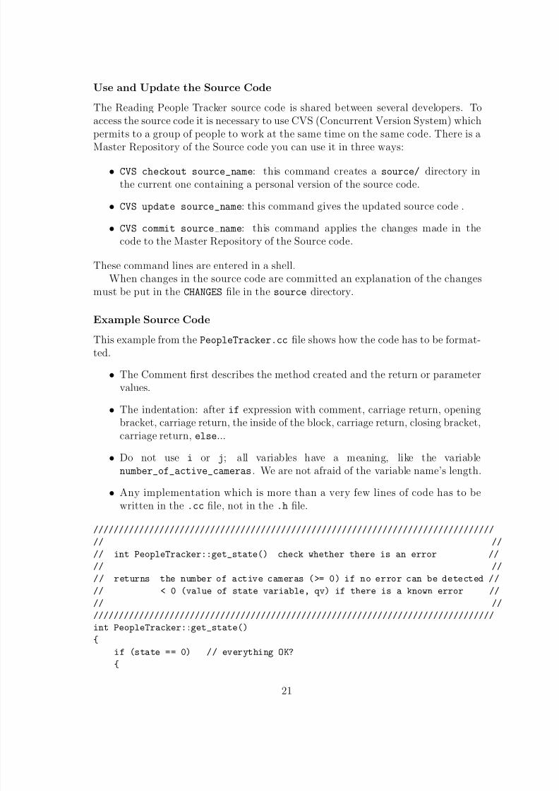
This example from the PeopleTracker.cc le shows how the code has to be format-ted.
• The Comment rst describes the method created and the return or parametervalues.
• The indentation: after if expression with comment, carriage return, openingbracket, carriage return, the inside of the block, carriage return, closing bracket,carriage return, else ...
• Do not use i or j ; all variables have a meaning, like the variablenumber_of_active_cameras . We are not afraid of the variable name’s length.
• Any implementation which is more than a very few lines of code has to bewritten in the .cc le, not in the .h le.
///////////////////////////////////////////////////////////////////////////////// //// int PeopleTracker::get_state() check whether there is an error //// //// returns the number of active cameras (>= 0) if no error can be detected //// < 0 (value of state variable, qv) if there is a known error //// /////////////////////////////////////////////////////////////////////////////////int PeopleTracker::get_state(){
if (state == 0) // everything OK?{
21

8/8/2019 RPT Manual 1.12
http://slidepdf.com/reader/full/rpt-manual-112 21/45
// count number of active cameras (ie. existing and enabled ‘Camera’s)unsigned int number_of_active_cameras = 0;unsigned int index;
for (index = 0; index < number_of_cameras; index++)if ((cameras[index] != NULL) && (cameras[index]->camera_enabled))
number_of_active_cameras++;
return number_of_active_cameras;}else{
assert (state < 0); // (state != 0) means error and this should be < 0return state; // this will hold an error value < 0
}}
3.3 Patterns Implementation
In this subsection we are dealing with the patterns and their implementation inthe Reading People Tracker. The system patterns are extracted from the DynamicOrganisation 2.2 and the main classes described are those from the tracking library.The patterns extracted are:
• The way the Inputs are treated: the Inputs class,
• The Tracking task: the ReadingPeopleTracker main class and thePeopleTracker, Camera, Tracking classes,
• The Results produced: the Results class.
We can easily understand that the most important part here is the tracking pattern,for this reason we will not present details about the fused results and output; theyare:
• in Standalone mode: User Interface,
•
in ADVISORmode: usage of XML standard Library.
3.3.1 Inputs
The Inputs class, shown in Figure 9, sets up video input, external motion input andcamera calibration. This class collect all input to given frame and returns actual andnew frame id.
1. CONSTRUCTOR:Inputs::Inputs(ConfigurationManager *configuration_manager) Cre-ates new conguration manger, Input conguration.
22

8/8/2019 RPT Manual 1.12
http://slidepdf.com/reader/full/rpt-manual-112 22/45
Configuration Manager
Inputs
Pnm Source
Calibration JPEG Source
Buffered Slave Image Source
Figure 9: Inputs diagram
2. DESTRUCTOR:Inputs::~Inputs() delete old sources.
3. Setup Inputs:void Inputs::setup_inputs()
• Setup video input,• Setup input for external motion detector:
– Motion image,– XML regions,– Background images.
• Setup camera Calibration.
4. Setup Buffered Slave:bool Inputs::setup_image_source_input(...) returns whether some validinput has been set up for the specied lename.
• Check for special lename “slave”. Use buffered slave input but fed froma le source. In order to do that, we determine and create le source rst,to get the image dimensions. Then we open the slave source.
• Open input_source which reads images from hard disk. The followingimage formats are recognised: JPEG, PPM, PGM (PNM formats may be
‘compress’ed or ‘gzip’ed).• Create slave source if we need it. Open slave source to be fed from
\input_source . This feed contains the image dimensions necessary toinstantiate the BufferedSlaveImageSource class.
5. Setup Buffer and XML Files:bool Inputs::setup_xml_region_source_input(...) Set up buffered slaveand le input XML region source as specied by the lename returns whethersome valid input has been set up.
23

8/8/2019 RPT Manual 1.12
http://slidepdf.com/reader/full/rpt-manual-112 23/45
• Check for special lename “slave”. Use buffered slave input which is fedwith input by Thales’ Wrapper. Get the image dimensions.
• Create a NumberedFileSource which reads XML data from hard disk.
Set up le source for the slave. This is a NumberedFileSource .6. Proceed Inputs:
frame_id_t Inputs::proceed_to_frame(...) First proceed thevideo_image_source to the next frame id with an id > = the givenone. Proceed all inputs to frame given frame_id_t next_frame_id , if possible and return actual new frame id. Then we use video_image_sourceas the denitive source for the frame id, proceeding other inputs to it. Therationale here is that if there is no video image for a given frame, no othersource needs to provide data for that frame.
• Get next video image, check for frame number wraparound, wrap aroundinput sources, e.g.. frame_id 999999 → 000000 within ADVISOR.• Choose latest background image: if input from slave, until buffer is empty.
3.3.2 ReadingPeopleTracker
The main() program for the Reading People Tracker. The diagram below shows theow of actions performed in the tracking task. When the ReadingPeopleTracker islaunched, it instantiates a PeopleTracker object which will starts the camera treat-ment threads.
1. The program starts PeopleTracker class:PeopleTracker *people_tracker = new PeopleTracker(config_filename)setup new PeopleTracker class,
2. Then The PeopleTracker adds cameras:people_tracker->add_cameras(number_of_cameras, camera_names) addcameras to the PeopleTracker,
3. Finally the PeopleTracker starts a processing thread:pthread_t people_tracker_thread = people_tracker->start_thread()starts a processing thread in PeopleTracker.
24

8/8/2019 RPT Manual 1.12
http://slidepdf.com/reader/full/rpt-manual-112 24/45
Camera 1 Camera 2
Create new objects
PeopleTrackerCamera
PeopleTracker
ReadingPeopleTracker
thread
thread
1 thread in Main starts
Camera 3
1 thread in PT starts
n thread for n Cameras starts
Figure 10: Objects creation and Threads sequence diagram
3.3.3 PeopleTracker
The PeopleTracker class handles and schedules trackers and outputs tracking re-sults. It instantiates Camera objects which in turn hold everything associated withthe respective camera: Inputs, Calibration, the actual Tracking class which generatesand stores results, a Conguration class etc. The PeopleTracker lets each Cameraclass start a thread. These wait for the PeopleTracker to supply the input (images,XML motion data). After tracking, they signal us that they have new results. The
PeopleTracker then extracts the results from the Camera and fuses data from allcameras in order to write the person/object tracks out in XML format.
INPUTS (XML)
ConfigurationManager
Camera
CalibrationInputs
Video ImagesBackground Images
Motion Images
Blob Data
PeopleTracker
OUTPUTS XML
Figure 11: PeopleTracker diagram
• CONSTRUCTOR:PeopleTracker::PeopleTracker(char *toplevel_config_filename)toplevel_config_filename is the base for all conguration le names.Other conguration les are generated by appending camera number (e.g.,LUL-conf1 -> LUL-conf1-01 for the rst camera) and initials of tracking
25

8/8/2019 RPT Manual 1.12
http://slidepdf.com/reader/full/rpt-manual-112 25/45
modules (e.g., LUL-conf1-01-RT for the RegionTracker of the rst camera).The constructor sets a state variable to the number of active cameras if thereis no error during set-up. Otherwise the state is set to a value < 0. Useget_state() to query this state.
• Setup conguration manager:configuration_manager = new ConfigurationManager
• Add new cameras:int PeopleTracker::add_cameras(unsigned int num_cameras,char *camera_names[]) Add a set of num_cameras cameras to the set of cam-eras known to the tracker. This will create a thread within each Camera,waiting for the arrival of data to be processed. The method returns < 0 onerror, otherwise number of new cameras added Within the ADVISORsystem,this will only be called once. However, the method handles the possibility toadd cameras at any time by calling it again.
• Start a thread for processing data:pthread_t PeopleTracker::start_thread() start a thread whichdoes all processing as data arrives and returns thread id.void *PeopleTracker::do_processing(void *unused) for each frame,wait until all cameras have new tracking data available then merge it andwrite it out in XML.
• Get the actual state of each cameras:
int PeopleTracker::get_state() check whether there is an error returnsthe number of active cameras ( > = 0) if no error can be detected < 0 (value of state variable, q.v.) if there is a known error.
• Write the results in XML format:unsigned char *PeopleTracker::write_results_in_XML_to_buffer(...)write out tracking results in XML to a given buffer (memory region) up tomaximum given length (give the buffer size) if no or NULL buffer is given it willbe allocated. returns a pointer to the rst char in the buffer with XML data.void PeopleTracker::write_results_in_XML_to_stream(ostream &out)write out tracking results in XML to a given ostream.
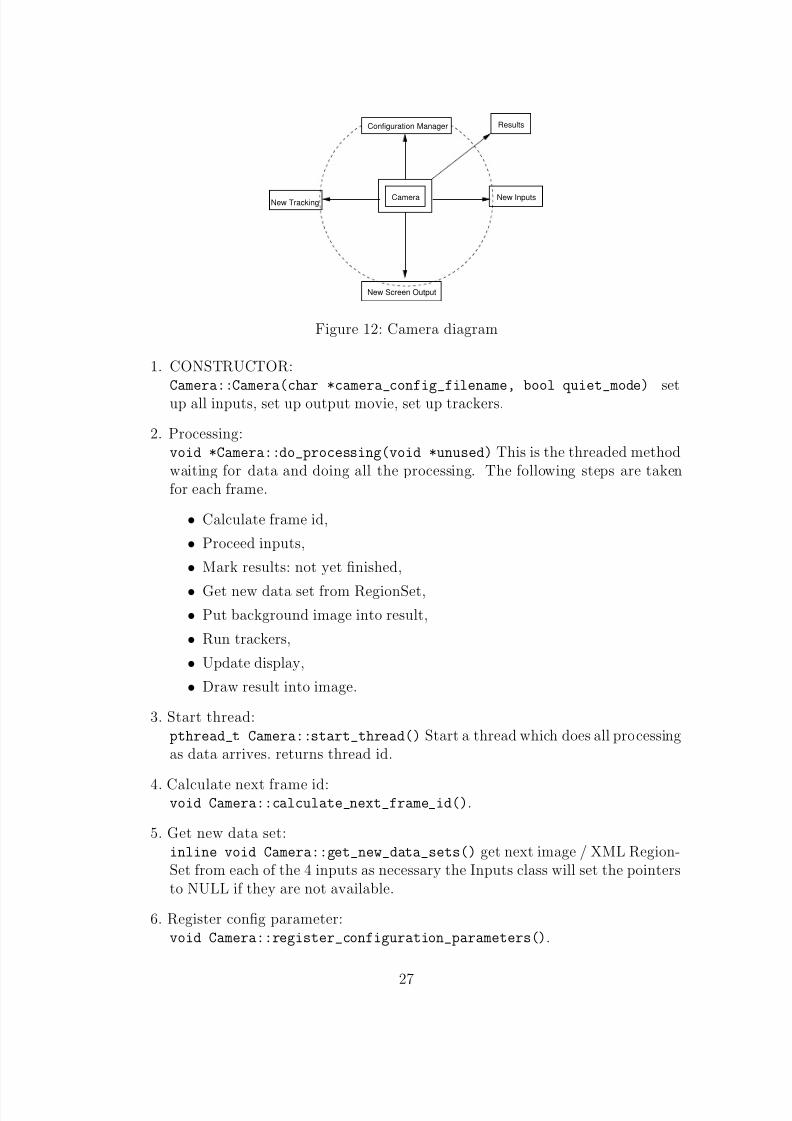
3.3.4 Camera
The Camera object holds everything associated with a camera: Inputs, Calibration,the actual Tracking class which generates and stores results, a CongurationMan-ager class etc. The PeopleTracker class can start a thread for each Camera classinstantiated and waits for input to be fed by the parent. Results from Tracking aregenerated by the thread and the availability of new Results is signalled.
26
8/8/2019 RPT Manual 1.12
http://slidepdf.com/reader/full/rpt-manual-112 26/45
Camera
Results
New Screen Output
Configuration Manager
New TrackingNew Inputs
Figure 12: Camera diagram
1. CONSTRUCTOR:Camera::Camera(char *camera_config_filename, bool quiet_mode) setup all inputs, set up output movie, set up trackers.
2. Processing:void *Camera::do_processing(void *unused) This is the threaded methodwaiting for data and doing all the processing. The following steps are takenfor each frame.
• Calculate frame id,• Proceed inputs,
• Mark results: not yet nished,• Get new data set from RegionSet,• Put background image into result,• Run trackers,• Update display,• Draw result into image.
3. Start thread:pthread_t Camera::start_thread() Start a thread which does all processing
as data arrives. returns thread id.4. Calculate next frame id:
void Camera::calculate_next_frame_id() .
5. Get new data set:inline void Camera::get_new_data_sets() get next image / XML Region-Set from each of the 4 inputs as necessary the Inputs class will set the pointersto NULL if they are not available.
6. Register cong parameter:void Camera::register_configuration_parameters() .
27

8/8/2019 RPT Manual 1.12
http://slidepdf.com/reader/full/rpt-manual-112 27/45
3.3.5 Tracking
The Tracking class is the nucleus of the tracking task. From this class are launchedall the different trackers and detectors. The trackers enabled in the the tracking
Conguration File are created: generation of a new conguration le for each trackerand start running them.
Region Tracker
Skeleton Tracker
Motion Detection
Active Shape Tracker
Occlusion ImageTracking
Configuration Manager
Human Feature Tracker
Figure 13: Tracking diagram
1. CONSTRUCTOR:Tracking::Tracking(ConfigurationManager *configuration_manager)
• The class checks which tracker is going to be used,• Then it initialise all variables in the conguration manager.
2. DESTRUCTOR:Tracking::~Tracking() deletes old congurations.
3. Setup trackers:void Tracking::setup_trackers(Inputs *inputs,unsigned char *camera_configuration_filename_base) generates trackerconguration le names by using the camera conguration le name and ap-pending a suffix, e.g. “-MD” for the Motion Detector module (generally, up-percase initials of modules)
• Setup le conguration,• Setup new tracker object.
4. Run trackers:void Tracking::run_trackers(Inputs *inputs, Results *results)
• Processing: Tracker → process frame,• Post processing: Tracker → process frame, this is a check against other
measurements again and clean up.
28

8/8/2019 RPT Manual 1.12
http://slidepdf.com/reader/full/rpt-manual-112 28/45
3.3.6 Results
The Results class is used as Storage class for tracking results. The results fromtracking will be added by the individual trackers This class is an Accessor and Mod-
ier to all the tracking results:inline TrackedObjectSet *get_tracked_objects()
{return tracked_objects;
}inline void set_tracked_objects(TrackedObjectSet *new_tracked_objects)
{tracked_objects = new_tracked_objects;
}inline Image *get_motion_image()
{return motion_image;
}inline void set_motion_image(Image *new_image)
{ motion_image = new_image;
}inline Image *get_background_image()
{return background_image;
}inline void set_background_image(Image *new_image)
{background_image = new_image;
}inline Image *get_difference_image()
{return difference_image;
}inline void set_difference_image(Image *new_image)
{difference_image = new_image;
}inline Image *get_thresholded_difference_image()
{return thresholded_difference_image;
}inline void set_thresholded_difference_image(Image *new_image)
{thresholded_difference_image = new_image;
}inline Image *get_filtered_difference_image()
{return filtered_difference_image;
29
8/8/2019 RPT Manual 1.12
http://slidepdf.com/reader/full/rpt-manual-112 29/45
}inline void set_filtered_difference_image(Image *new_image)
{filtered_difference_image = new_image;
}
4 How to Create or Design and Implement...
A new module for the PeopleTracker should be carefully designed using RationalRose to draw the diagrams needed. Then implement the new module using the ClassDiagram and localise the changes required by the new module, following the rulesgiven in section 3.2.2. This section deals with the design aspect of creating a newImage Source, a new Tracker and a new Detector modules.
4.1 A New Shape Model
To build a new linear shape model for people tracking. The model provided wasoptimised using a technique published in [ 12]. The basic components are segmentedtraining images and the tracker classes. Basically the idea is to build the initialmodel and then use the tracker to t the deformable model to the original segmentedtraining images. A new linear model is generated with this new training data andthe process repeated. The models obtained are more compact (i.e. fewer shapeparameters are required).
It required a short sequence of steps for the implementation 1 .
1. Generate training images - segmented binary images with a single trainingshape in each,
2. Extract training shapes as B-splines ,
3. Align splines (using process_sequence ),
4. Build PCA shape model (using process_squence ) and output to current modelle,
5. Add small amount of noise to shape model (use PCAclass::add_noise ),
6. Run the tracker with current model on segmented training images. We considereach training image as a sub-sequence of “n” identical images. The tracker isrun on each sub-sequence so that the nal shape has had a chance to convergeonto the precise training image shape.
7. Output all the “tracked” training shapes (as B-splines ).
8. goto 3.1 The given algorithm was kindly provided by Adam Baumberg in a personal communication on
Wed Jun 5 2002
30

8/8/2019 RPT Manual 1.12
http://slidepdf.com/reader/full/rpt-manual-112 30/45
Step 5 is needed to ensure the t to the training shapes does not degrade over time.However for a large training set and a couple of iterations it is not critical. Thereused to be a short program called add noise.cc that did this, however, this programis not a part of the current distribution.
4.2 A New ImageSource
This section provides the standard approach for creating a new image source. Therules given in section 3.2.2 have to be followed.
All image input should be through an ImageSource class. The basic structure of an Image Source class is as follow:
• The Constructor initialises or opens the input and makes sure that imagescan be read. The variable concerning the source type are also set up. Calling
the Constructor has to return valid values concerning the image settings: e.g.the image dimensions (xdim, ydim), and if it is a grey scale image, frame time(in ms) and frame id.
• The Image *current points to the current image if there is one.
• The get_current method dened in ImageSource class, gets the current imageor frame.
• The get_next method gets the next image or frame. If it is the rst imagethe method returns the rst image and get_current may not be called. Theget_next method will modify the value of the current pointer.
• The get_xdim() and get_ydim() have to be implemented as const and haveto return unsigned int representing the image dimensions.
For Example for the actual state of the code: JPEGSource and PNMSource derivedfrom ImageSource class.
4.3 A New Tracker or Detector Module
This section provides the standard approach for creating a new tracker or detector.First of all, it is important to understand the Inputs and Outputs or Results expectedand used or generated by these modules. Then we will look more precisely at thebasic methods which have to be used for the frame processing.
4.3.1 Inputs and Results
Inputs
The Inputs to ReadingPeopleTracker are:
• external for the ADVISORsubsystem see section 3.2.1
• internal for Standalone: they are les stored in the hard drive (video images),
31

8/8/2019 RPT Manual 1.12
http://slidepdf.com/reader/full/rpt-manual-112 31/45
• Calibration inputs if there are some.
Results
All data are exchanged via a central class Results . The results are the outputs of the ReadingPeopleTracker . This results contain:
• Images: motion image, background image, difference image and threshold im-age.
• TrackedObjectSet:
– Can contain invisible (not detected) hypotheses or predictions– Tracking result/output:
∗ only Prole,∗ only older result,∗ only visible.
– Observation class: for each region or prole detected is associated an newObservation object which will date the frames of the region or prole.
For Example:class Profile → class ProfileSet : Observation ,class Region → class RegionSet : Observation ,class NewX→ class NewXSet : Observation .
4.3.2 Frame ProcessingEach tracker or detector use two methods to do the frame processing.
• process_frame(Inputs *inputs, Results *results,unsigned int max_objects) : use inputs and current/previous results to ob-
tain and store new results. This method call three other ones:
– predict_old_objects(Results *previous_results) ,– track_old_objects(Inputs *inputs, Results *results) ,– detect_new_objects(Inputs *inputs, Results *results) .
• post_process_frame(Inputs *inputs, Results *results) : clean uptracks etc in results.
4.3.3 Detection
• Measurements: each picture is compared to the original or updated back-ground.
• No “memory”: blob is simply detected (just detected) at the instant t.
For these reasons there is no need for a post_process_frame() , as there is nothingto clean.
32

8/8/2019 RPT Manual 1.12
http://slidepdf.com/reader/full/rpt-manual-112 32/45
4.3.4 Tracking
The tracking module includes the detection module.
•
Over the time: the aim is to follow one or many blobs, used of track_old_objects()
• Measurements: the measurements are done in a loop which predicts the positionof an object for the next frame. The previous results are stored in current . Itis checked if the prediction was right.
– yourself (AST):,
– other modules (RT).
4.3.5 Base Tracker
The BaseTracker class is the base class for the detection and tracking modules. Themethods used in the tracker or detector are declared in BaseTracker.h as publicand as virtual .
4.4 Actual Conguration And Algorithm Of The TrackingTask
The actual tracking is done via 4 modules:
• MotionDetector,
• RegionTracker,
• ActiveShapeTracker,
• HeadDetector.
Figure 14 shows the organisation of the tracking and detection modules and howthese modules interact with each other from the input to the output. The videoinput is taken by the MotionDetector module. This module applies some lteringto the image and obtains detected regions:
• Median Filtering on the background image,
• Background Subtraction with the image with moving people.
• After ltering and thresholding the Motion Image is obtained,
• The moving blobs are extracted.
The detected regions are used as input for the RegionTracker module:
• The rst task here is the splitting and merging regions,
33

8/8/2019 RPT Manual 1.12
http://slidepdf.com/reader/full/rpt-manual-112 33/45
DetectedHead Positions
head detection
Head Detector
TrackingOutput
Video image
RegionsPredicted
RegionsStatic
UnmatchedPred. Regions
Pred. RegionsStill Unmatched
Tracked RegionsRevised
Identified andNew Regions
RegionsProcessed
filtering by age
prediction and
matching
prediction
matching
moving again
Region splitting and merging
Region Tracker
removal if
Background Image
Difference Image
Motion Image
RegionsDetected
filtering and differencing
extracting moving blobs
filtering and thresholding
me[di]an filtering
Motion Detector
incorporation
HypothesisedProfiles Profiles
Predicted
RevisedTracked Profiles
New ProfilesIdentified and
Pred. ProfilesUnmatched
shape fitting
mean shape
prediction and
filtering by age
or mean shapeoutline tracing
for edgeslocal search
matching andremoving doubles
prediction
Active Shape Tracker
Figure 14: Tracking Algorithm (taken from [13])
• Then the program tries to match these region with the human features data.
• When a static region is detected, the program adds the region to the back-ground image.
The HeadDetector module takes its input from the identied region fromRegionTracker module. The Image difference obtained in the MotionDetector isuse as input in ActiveShapeTracker module. The region identied result fromRegionTracker module is used by HeadDetector and ActiveShapeTracker mod-ules. Then the HeadDetector module provides information about the mean proleto ActiveShapeTracker module:
• First the module make some hypothesis on the prole of the region detected
using data from RT and HD,• Then the module try to t a shape onto this region,
• When the new prole is identify the output conrm the others on the Trackingoutput.
5 Conguration Files Organisation
The diagram below shows the architecture organisation of the Conguration les.The Top Level Conguration le contains informations about the cameras enabled
34

8/8/2019 RPT Manual 1.12
http://slidepdf.com/reader/full/rpt-manual-112 34/45
and their conguration le names. For example the name of the top level congu-ration le is TLC-00 and this le contains the name of the camera(s) congurationle(s) TLC-00.PTLF0n.C0n (n is the camera number 1 to 4). Each camera congura-tion le contains information on the trackers used and their conguration le namesfor example the Region tracker le name will be TLC-00.PTLF0n.C0n-RT .
REGION TRACKER
MOTION DETECTOR
HUMAN FEATURE TRACKER
CAMERA
ACTIVE SHAPE TRACKER
SKELETON TRACKER
CAMERA file name TLC−00−PTLF0n.C0nRT file name TLC−00−PTLF0n.C0n−RT
MD file name TLC−00−PTLF0n.C0n−MD
HFT file name TLC−00−PTLF0n.C0n−HFT
AST file name TLC−00−PTLF0n.C0n−AST
ST file name TLC−00−PTLF0n.C0n−ST
TOP LEVEL CONFIGURATION FILE
CAMERA_n_NAME PTLF0n.C0nTLC file name TLC−00
Figure 15: Conguration File Organisation diagram
6 Libraries DescriptionThis subsection deals with the 7 libraries and the most prominent classes of the Read-ing People Tracker. It contains information about class denitions and descriptionof their behaviour.
• The PCA library :
– PCAclass.cc : denes the PCAclass which is a class for carrying out Prin-cipal Component Analysis on arbitrary data.
– MeanProfile.cc : denes the MeanProfile which is a class for calculating
an updated mean prole.– HMetric.cc : dene the HMetric class.– ProfileSequence.cc : dene the ProfileSequence which is a class which
allows a number of manipulations to ProfileSet stored in le. Only usedby the process sequence program to generate and manipulate PCA models.
• The matrix library :
– KalmanFilter.cc : denes the DynamicKalmanOneD ,DynamicKalmanTwoD , StaticKalmanOneD and StaticKalmanTwoDand the VibrationFilter classes.
35
8/8/2019 RPT Manual 1.12
http://slidepdf.com/reader/full/rpt-manual-112 35/45
– NagMatrix.cc : denes the NagMatrix which is a class for manipulating(2D) matrices (uses either NAG or BLAS/LAPACK library).
– NagVector.cc : denes the NagVector which is a class for manipulating
realno n-vectors.• The utils library :
– ConfigurationManager.cc (formerly GlobalsManager.cc): denesConfigurationManager plus help classes for String and handy variablesconguration (derived from a base class ConfigurationVariable ).
– NumberedFiles.cc : denes NumbreredFiles which is a helper (base)class to read or write numbered les. Derive a class from this one. Giverst lename (e.g., video017.jpg) as parameter to this base class’s con-structor.
– Profiling.cc : denes Profiling class which do some very basic routinesfor timing events.
• The data library :
– BoundaryPoints.cc : denes BoundaryPoints class which ordered set of points on the boundary of an object.
– HumanFeatureSet.cc : denes HumanFeatureSet class which provides alist of tracked objects with detected human features such as head positionsetc.
– HumanFeatures.cc : denes HumanFeatures class which provides somedenitions and structures for human features such as head positions etc.
– Observation.cc : denes Observation class which is a base storage classfor an observation: a Region, Prole etc.
– PointVector.cc : denes PointVector which is a class for manipulatinga N point vector.
– Profile.cc : denes Profile which is a record class for storing the Proledata of an object.
– ProfileSet.cc : denes ProfileSet which is a class consisting of a listof Proles.
– Region.cc : denes Region class which is a Region is a rectangular subimage and will in general contain one connected blob.
– RegionSet.cc : denes RegionSet class which contains functions forRegionSet class (declared in Region.h).
– Skeleton.cc : denes Skeleton class which provides some denitions andstructures for a human “skeleton”.
– SkeletonSet.cc : denes SkeletonSet class which provides a list of tracked objects with detected Skeleton.
36

8/8/2019 RPT Manual 1.12
http://slidepdf.com/reader/full/rpt-manual-112 36/45
– SplineMatrix.cc : denes SplineMatrix class with methods to converta Region Boundary to spline form.
– SplineWeights.cc : denes SplineWeights class.
• The imgsrc library :
– BufferedSlaveImageSource.cc : denes BufferedSlaveImageSourceclass, an ImageSource which waits for external images usingpthread_cond_wait .
– Grey8Image.cc : denes Grey8Image.cc image class for 8-bit grey levelimages.
– GreyMap.cc : denes GammaCorrectMap class.
– HSV32Image.cc (most of this was copied from RGB32Image.cc): denes
HSV32Image class, HSV image class derived from RGB32Image class.– Image.cc : denes Image class.
– ImagePyramid.cc : denes ImagePyramid class.
– ImageSource.cc : denes ImageSource class.– JPEGSource.cc (structure copied from MpegStream.cc by Adam Baum-
berg) (based on our new (JPEG) MovieStore and IJG’s example.c): de-nes JPEGSource class which reads individual, numbered JPEG les asan ImageSource. This code is written with full colour images in mind(24/32-bit).
– Kernel.cc : denes Kernel class for image processing.– MedianFilterSource.cc : denes MedianFilterSource class for a
median-ltered background image median lter (over time) to extractbackground dened as a PipeSource.
– MovieStore.cc (structure copied from moviestore.cc.amb by AdamBaumberg): denes MovieStore class which stores a sequence of imagesin a number of formats (future). Currently, only individual JPEG im-ages can be written. This code is written with full colour images in mind(24/32-bit).
– MultiBackgroundSource.h : denes MultiBackgroundSource classwhich is a background generation class which lets you incorporate staticobjects into the background and remove them when they start movingagain. Written with cars (ie unidentied, large ‘Region’s) in mind. Thisle is not directly included. We are included by PipeSource.h.
– PipeSource.h : denes PipeSource class.– PipeSourceFilters.h : denes BlendSource , BlurSource ,
ColourFilterSource , ConcatSource , ConvolveSource ,ConstantSource , DifferenceSource , FMedSource ,GammaCorrectSource , HSV32Source , HalfBlurSource , MaximumSource ,
37

8/8/2019 RPT Manual 1.12
http://slidepdf.com/reader/full/rpt-manual-112 37/45
MinimumSource , MiddleSource , NoisySource , NeighbourSource ,RepeatSource , RotateSource , ResampleSource , VFlipSource ,ThresholdSource , ThresholdedDifferenceSource , SobelEdgeSource ,SobelSource , SubImageSource , SimpleDiffSource , SkipSource classes.This le is not directly included. We are included by PipeSource.h.
– PnmSource.cc : denes PnmSource class which is an utility function toread a PNM le header; returns 5 for P5 etc, 0 for error. NOTE: does notopen or close le. Leaves le pointer at rst data byte.
– PnmStream.h : denes PnmStream which passes a Unix command that willgenerate a stream of PNM images to stdout OR simply an input streamcontaining PNM images. This class connects to the stream to gener-ate images accessed using the get_next() function note the get_next()method is implemented in PgmSource.cc .
– RGB32Image.cc : denes RGB32Image class which 24-bit (plus al-pha) colour image class derived from generic. Image class inImage.h/Image.cc .
– XanimStream.h : denes XanimStream class.
• The tracking library :
– ActiveModel.cc : denes ActiveModel class.
– ActiveShapeTracker.cc : denes ActiveShapeTracker class which is ahigh level people tracker without ground plane info.
– BaseTracker.cc : denes BaseTracker class.– Calibration.cc : denes Calibration class which reads a calibration
(4x3 projection) matrix from le and provides methods to use this cali-bration data for image measurements. The matrix le must be in NAGformat, image addressing mode is expected to be IA_TOP_TO_BOTTOM, andusing the unit [cm] for world coordinates.
– Camera.cc : denes Camera class which holds everything connected witha camera. A Camera object holds everything associated with a cam-era: Inputs, Calibration, the actual Tracking class which generates and
stores results, a CameraConguration class etc. The Camera class startsa thread for each Camera class and waits for input to be fed by the parent.Results from Tracking, are generated and the availability of new Resultsis signalled.
– CameraConfiguration.h : denes CameraConfiguration class.
– EdgeDetector.cc : denes NormForeColourDetect class which uses acombination of *normalised *colour subtraction and inside normalisedcolour (from previous frames), ColouredForegroundEdgeDetector classwhich use a combination of colour image subtraction and in-side colour (from previous frames), ColouredEdgeDetector class,
38

8/8/2019 RPT Manual 1.12
http://slidepdf.com/reader/full/rpt-manual-112 38/45
ForegroundEdgeDetector class, MovingEdgeDetector class which islooking at spatial and temporal derivative but do not assume back-ground image is available, SimpleEdgeDetector class, SobelDetectorclass, GenericEdgeDetector class.
– HumanFeatureTracker.cc (structure copied from ActiveShape-Tracker.cc): denes HumanFeatureTracker class which is a trackerclass which tracks human features such as head etc.
– Inputs.cc : denes Inputs class.– MotionDetector.cc : denes MotionDetector class which support for
external motion image source. Concept for creation of motion image,colour ltering techniques, pre-calculated difference image, dilation formotion image.
– OcclusionHandler.h : denes OcclusionHandler base class to handleocclusion.
– OcclusionImage.cc : denes OcclusionImage class.– PeopleTracker.cc : denes PeopleTracker class handles and schedules
trackers and outputs tracking results.– RegionTracker.cc : denes RegionTracker class which tracks regions
from frame to frame.– ScreenOutput.cc
– SkeletonTracker.cc (structure copied from HumanFeatureTracker.h ):
denesSkeletonTracker
class which tracks a humans “skeleton”.– TrackedObject.cc : storage class for tracked objects (person, group, car,other) holding all data from all trackers.
– TrackedObjectSet.cc : denes TrackedObjectSet class which lists tohold ‘TrackedObject’s.
– Tracking.cc
• The XML library :
– BufferedSlaveXMLRegionSource.cc : in this le we dene theBufferedSlaveXMLRegionSource class which denes an interface toXML Region data as dened by the XML Schema namespacehttp://www.cvg.cs.reading.ac.uk/ADVISOR (the current name). Aninstance of this class will read and buffer XML data given throughhandle_new_blob_data(...) until it is queried by get_next() .
get_next() will parse the XML data, return a RegionSet and deletethe XML buffer.
– XMLRegionHandler.cc : denes XMLRegionHandler class which denes aninterface to XML Region data as dened by the XML Schema namespacehttp://www.cvg.cs.reading.ac.uk/ADVISOR (the current name). Sim-ilar in design to our ImageSource classes, some methods are pure virtual
39

8/8/2019 RPT Manual 1.12
http://slidepdf.com/reader/full/rpt-manual-112 39/45
and the class should therefore not be instantiated directly. The XMLRe-gionHandler class is derived from the XML SAX2 DefaultHandler classwhich is designed to ignore all requests. We only redene the methodsthat we need such that there is little overhead.
– XMLRegionSource.cc (abstract): this class denes an interface toXML Region data as dened by the XML Schema namespace“http://www.cvg.cs.reading.ac.uk/ADVISOR” (the current name). Sim-ilar in design to our ImageSource classes, some methods are pure virtualand the class should therefore not be instantiated directly. The XMLRe-gionSource class uses the XMLRegionHandler class to extract data fromthe XML structures.
7 Reverse engineering of the RPT code using Ra-tional Rose’s C++ Analyser Module
This section explains how to do the analyse of the RPT code in order to obtainthe class diagram structure. The rst stage of the analysis is to use Rational RoseC++Analyser and launch the analysis tool. When this analysis is successful the projectis exported under the Rational Rose Professional C++ Edition which will generateclass diagrams of the code.
7.1 Rational Rose C++ Analyser
Open a new project, then add all the source les (*.cc) and the libraries les (*.h,*.hpp). Include all the libraries, not only the one created for the software (ie:#include<standard_library.h> and #include ‘‘personal_library’’ ). Finallydene some variables used by the libraries. If tick have been added to the (R) infront of the libraries path the les will be analysed ( the analyser will generate lotsof mistakes if the standard libraries are analysed).
Environment Conguration: By default the C++ Analyser is congured as FileName Case Sensitivity set to “insensitive”. So, in order to be able to make theanalysis correctly the parameter must be changed to “sensitive”.
40

8/8/2019 RPT Manual 1.12
http://slidepdf.com/reader/full/rpt-manual-112 40/45
Figure 16: File Name Case Sensitivity conguration Edit/Preferences...
The next step is to set the map path of the les locations in order to indicateto the C++ Analyser where the les to be analysed are situated on the harddrive.
Figure 17: Map path data conguration Edit/Path Map...
41

8/8/2019 RPT Manual 1.12
http://slidepdf.com/reader/full/rpt-manual-112 41/45
Figure 18: Map path user data conguration Edit/Path Map...
Create a new project: when the analyser is congured properly create a newproject File/New. Add to this project all the les to analyse.
Include all les (source code and libraries): this step is an important one, addto the project all the les to be analysed, this includes all the libraries(#include <...> and #include "..." ).
Figure 19: Open and include data sources Edit/File List...
Dene variables: as the program uses some global variables, you have to denethem in the analyser.
42

8/8/2019 RPT Manual 1.12
http://slidepdf.com/reader/full/rpt-manual-112 42/45
Figure 20: Global variables denition Edit/Dened Symbols...
launch the analysis process: when you have included all the les and dening allvariables you can run the analyse: Action/Analyse
Export to Rational Rose
7.2 Error Messages
If you obtain error messages like:
• Cannot include <library.h> or ‘‘library.h’’ : you probably forget to in-clude this le in the project le,
• Cannot nd anything named: you probably haven’t included all the libraries.
• The inclusion of this library introduces a circular dependency: declare the leas Type 2 and go to Edit then Type 2 Contexts and edit it including the lewhich generates the error.
43

8/8/2019 RPT Manual 1.12
http://slidepdf.com/reader/full/rpt-manual-112 43/45
Figure 21: Edition of the type2 inclusions Edit/Type 2 Contexts...
44

8/8/2019 RPT Manual 1.12
http://slidepdf.com/reader/full/rpt-manual-112 44/45
References
[1] M. Satpathy, N. T. Siebel, and D. Rodrıguez, “Maintenance of ob ject orientedsystems through re-engineering: A case study,” in Proceedings of the IEEE Inter-national Conference on Software Maintenance (ICSM 2002), Montreal, Canada ,pp. 540–549, October 2002.
[2] A. M. Baumberg, Learning Deformable Models for Tracking Human Motion .PhD thesis, School of Computer Studies, University of Leeds, Leeds, UK, Octo-ber 1995. ftp://ftp.comp.leeds.ac.uk/comp/doc/theses/baumberg.ps.gz .
[3] P. Remagnino, A. M. Baumberg, T. Grove, T. Tan, D. Hogg, K. Baker, andA. Worrall, “An integrated traffic and pedestrian model-based vision system,”in Proceedings of the Eighth British Machine Vision Conference (BMVC97)(A. Clark, ed.), pp. 380–389, BMVA Press, 1997.
[4] Rational Software Corporation, Cupertino, USA, Rational Rose 2000e , 2000.
[5] S. Demeyer, S. Ducasse, and O. Nierstrasz, “Finding refactorings via changemetrics,” in Proceedings of the 2000 ACM SIGPLAN Conference on Object-Oriented Programming, Systems, Languages and Applications (OOPSLA 2000) ,pp. 166–177, October 2000.
[6] D. Gries, The Science of Programming . New York, USA: Springer-Verlag, 1981.
[7] T. Richner and S. Ducasse, “Recovering high-level views of object-oriented ap-
plications from static and dynamic information,” in Proceedings of the 1999 International Conference of Software Maintenance (ICSM ’99) , pp. 13–22, Au-gust 1999.
[8] J. Rumbaugh, I. Jacobson, and G. Booch, The Unied Modeling Language Ref-erence Manual . Reading, USA: Addison-Wesley, 1999.
[9] N. T. Siebel and S. Maybank, “Fusion of multiple tracking algorithms for robustpeople tracking,” in Proceedings of the 7th European Conference on Computer Vision (ECCV 2002), K obenhavn, Denmark (A. Heyden, G. Sparr, M. Nielsen,and P. Johansen, eds.), vol. IV, pp. 373–387, May 2002.
[10] F. Buschmann, R. Meunier, H. Rohnert, P. Sommerlad, and M. Stal, Pattern-Oriented Software Architecture . Wiley, 2000.
[11] M. Henricson and E. Nyquist, Programming in C++ Rules and Recommenda-tions . Ellemtel Telecomminucation System Laboratories, Alvsjo, Sweden, 1992.
[12] A. M. Baumberg and D. Hogg, “An adaptive eigenshapemodel,” in Proceedings of the Sixth British Machine Vi-sion Conference (BMVC95) , vol. 1, pp. 87–96, 1995.http://www.scs.leeds.ac.uk/vision/proj/amb/Postscript/bmvc2.ps.Z .
45

8/8/2019 RPT Manual 1.12
http://slidepdf.com/reader/full/rpt-manual-112 45/45
[13] N. T. Siebel, Designing and Implementing People Tracking Applications for Au-tomated Visual Surveillance . PhD thesis, Department of Computer Science, TheUniversity of Reading, Reading, UK, January 2003. To appear.