RPL: WME 0500S, Magnitude Magnetic Bearing Centrifugal...
69
Replacement Parts List No. 0700017600 Revision AF 11/2017 Daikin Daikin McQuay McQuay Magnitude TM Magnetic Bearing Centrifugal Chiller WME 0500 To find your Daikin Applied parts distributor, call 1-800-377-2787 or visit www.DaikinApplied.com
-
Upload
trinhthuan -
Category
Documents
-
view
238 -
download
2
Transcript of RPL: WME 0500S, Magnitude Magnetic Bearing Centrifugal...

Replacement Parts List No. 0700017600 Revision AF 11/2017
DaikinDaikin McQuay
McQuay
MagnitudeTM Magnetic Bearing
Centrifugal ChillerWME0500
To find your Daikin Applied parts distributor, call 1-800-377-2787 or visit www.DaikinApplied.com

WME0500S- Water Cooled Chiller Rev. AF 11/17 RPL 7000176 / Page 2
ContentsParts List Revision History ............................................................................................................................. 3Unit Nomenclature Model Number Nomenclature ........................................................................................................................ 4 Serial Number Nomenclature ......................................................................................................................... 4 Model Number- Complete ........................................................................................................................ 5- 10 Electrical Legend ............................................................................................................................................11Controls Main Control Box ...................................................................................................................................... 12 VFD Enclosure .......................................................................................................................................... 13 VFD Chassis ........................................................................................................................................ 14, 15 Compressor Wiring Harness ...................................................................................................................... 15
VFD Power Supply Plate .................................................................................................................... 16, 17 OITS- Operator Interface Touch Screen Panel and Rapid Restore ........................................................... 18Control Sensors 087 Impeller Units Sensor Location Diagrams .......................................................................................... 19 092 Impeller Units Sensor Location Diagrams .......................................................................................... 20 Components .............................................................................................................................................. 21Compressor Motor/Bearing Assemblies ........................................................................................................................ 22 Motor/Bearing Assembly Components ...................................................................................................... 23 087 Impeller- (Compressor Revision/Code 07= AAA) Impeller Assembly .............................................................................................................................. 24 Impeller Seal & Compressor Fittings ............................................................................................ 25, 26
Discharge Housing & High Speed Shaft Seal .................................................................................... 27 Inlet Assembly .............................................................................................................................. 28, 29 092 Impeller- (Compressor Revision/Code 07= AAB) Impeller Assembly .............................................................................................................................. 30 Impeller Seal & Compressor Fittings ............................................................................................ 31, 32 Discharge Housing & High Speed Shaft Seal .................................................................................... 33 Inlet Assembly .............................................................................................................................. 34, 35Unit Assembly Relief & Shutoff Valves ........................................................................................................................ 36, 37 Discharge Piping Stack ....................................................................................................................... 38, 39 Hot Gas Bypass 092 Impeller .............................................................................................................. 40, 41 Suction Piping ..................................................................................................................................... 42, 43 Liquid Injection .......................................................................................................................................... 44 Rotor Cooling 087 Impeller ................................................................................................................. 45, 46 Rotor Cooling 092 Impeller ................................................................................................................. 47- 49 Stator Cooling 087 Impeller ................................................................................................................ 50, 51 Stator Cooling 092 Impeller ................................................................................................................ 52, 53 VFD Cooling .............................................................................................................................................. 54 Liquid Line ........................................................................................................................................... 55, 56Condenser Diagrams ................................................................................................................................................... 57 26" Condenser Heads, Head Gaskets & Hardware ............................................................................ 58, 59 30" Condenser Heads, Head Gaskets & Hardware ............................................................................ 60, 61 Tube Counts, Tubes, Sight Glass, Shut Off Valve & Gasket, Charge Valve & Cap .................................. 62Evaporator Diagrams ................................................................................................................................................... 63 30" Evaporator Heads, Head Gaskets & Hardware ............................................................................ 64, 65 36" Evaporator Heads, Head Gaskets & Hardware ............................................................................ 66, 67 Tube Counts, Tubes, Sight Glass, Charge Valve & Cap ........................................................................... 68
Critical Parts List ....................................................................................................................................... CPL1

WME0500S- Water Cooled Chiller Rev. AF 11/17 RPL 7000176 / Page 3
Revision Date Description Revisions A thru Z and AA thru AB have been archived. AC 09/2015 Page 14: Added Bubble Ref. 16. Page 15: Added Backup Battery for VFD Controller and Ref. 16 Wire Harness/Cable Kit and Footnote #2. Page 21: Updated p/n for S07 & S13 Sensors, was 071568601. Updated p/n for S11, was 071568511. Page 23: Changed Ref. 8 to 8A. Added p/n and Bubble for Ref. 8B. Removed Footnote 3. Page 32: Added footnote #4 to Ref. 505. Page 53: Corrected p/n for Ref. 026 Coil-Sol Valve, was 331796054. Pages 57 & 62: Added Bub. Ref. 252 (Screw) and 253 (Gasket). Page 68: Corrected p/n for Ref. 331, was 073249901. CPL1: Added Critical Parts List. AD 05/2016 Page 5: Corrected Code 9 Evap Tube Count for Mixed Diameter Tubes. Page 6: Corrected Code 17 Cond Tube Count for Mixed Diameter Tubes. Page 23: Added components for Compressor Controller Module. AE 10/2017 Pages 5-10: Updated Code Index. Page 17: Added Amp descriptions to Ref. 20, 21, 22 Fuses. Page 41: Corrected qty for Ref. 020 Expansion Valve, qty was 4. Page 57: Corrected diagram for Condenser Water Box Head option. Page 62: Corrected description and qtys for Ref. 330 Condenser Charge Valves. Page 63: Corrected diagram for Evaporator Water Box Head option. Page 68: Corrected description and qtys for Ref. 330 Evaporator Charge Valves. AF 11/2017 Page 21: Updated info for Transducers to include part #s for units built before & after Sept. 2017. CPL1: Updated info for Transducers to include part #s for units built before & after Sept. 2017.
Parts List Revision History
Daikin Applied, 13600 Industrial Park Blvd., P.O. Box 1551, Minneapolis, MN 55440 (763) 553-5330
WME0500S- Water Cooled Chiller Rev. AF 11/17 RPL 7000176 / Page 4
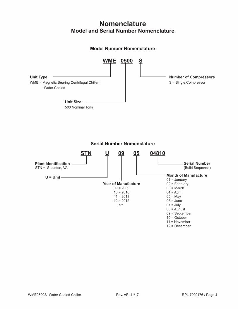
NomenclatureModel and Serial Number Nomenclature
STN U 09 05 04810
Plant IdentificationSTN = Staunton, VA
Serial Number (Build Sequence)
U = Unit
Model Number Nomenclature
Year of Manufacture09 = 200910 = 201011 = 201112 = 2012
etc.
Month of Manufacture01 = January02 = February03 = March04 = April05 = May06 = June 07 = July08 = August09 = September10 = October11 = November12 = December
Serial Number Nomenclature
WME 0500 S
Unit Size: 500 Nominal Tons
Number of CompressorsS = Single Compressor
Unit Type:WME = Magnetic Bearing Centrifugal Chiller, Water Cooled

WME0500S- Water Cooled Chiller Rev. AF 11/17 RPL 7000176 / Page 5
Code: WME 0500S S M2 S S AAB E3012 BE 2RA C4 0440 CC Y A C3012 BLYY Code No.: 1 2 3 4 5 6 7 8 9 10 11 12 13 14 15 16 17
NomenclatureModel Number- Complete
2RA C4 1050 CC Y A A 134 082 E1 YY EAYYYY YYYYYYYY YYYY 18 19 20 21 22 23 24 25 26 27 28 29 30 31
H2 B 1 4 A Y Y Y 1 B A 0150 U Y Y Y Y Y Y Y 0 A VFDM 32 33 34 35 36 37 38 39 40 41 42 43 44 45 46 47 48 48 49 50 51 52 53
1. Model Type WME= Magnetic Bearing Centrifugal Chiller, Water Cooled
2. Unit Size / Number of Compressors First 4 Digits= Unit Size in Nominal Tons 0500= 500 Ton Fifth Digit= Number of Compressors S= Single Compressor
3. Refrigerant Circuiting S= Single Circuit
4. Motor Code M2= 3 Winding, 3PH, 440- 575V; M3= 1 Winding, 6PH, 380- 575V
5. Voltage Code U= 380/60; A= 440/60; R= 460/60; S= 480/60; D= 575/60; F 380/50; G= 400/50; K= 415/50
6. Sound Reduction Package S= Sound Reduction Package
7. Compressor Revision Level AAA= Compressor Revision Level (087 Impeller); AAB= Compressor Revision Level (092 Impeller) 8. Evaporator Shell Size E3012= Evaporator, 30" Diameter/12' Long; E3612= Evaporator, 36" Diameter/12' Long
9. Evaporator Tube Count / Tube Type First Digit= Tube Count; 3/4" Diameter Tube 30" Diameter: B= 300; C=262; X=Special 36" Diameter: B= 488; C= 414; D= 352; X= Special First Digit= Tube Count; 1" Diameter Tube 30" Diameter: E= 178; F= 149; X= Special 36" Diameter: E= 271; F= 243; G= 209; X= Special First Digit= Tube Count; Mixed Diameter Tube 30" Diameter: J= 155(3/4" tubes)+90(1" tubes); K= 127(3/4" tubes)+81(1" tubes); X= Special 36" Diameter: J= 244(3/4" tubes)+136(1" tubes); K= 215(3/4" tubes)+108(1" tubes); M= 179(3/4" tubes)+95(1" tubes); X= Special Second Digit= Tube Type E= Turbo EHP .025 Wall, 3/4"; F= Turbo EHP .028 Wall, 3/4"; Q= Turbo EHP .035 Wall, 3/4"; T= TC SS 28FPI .028 Wall, 3/4"; Z= TC Titanium 32FPI .028 Wall, 3/4"; G= CU Turbo .025 Wall, 1"; D= CU Turbo .028 Wall, 1"; H= CU Turbo .035 Wall, 1"; U= CU Turbo .025 Wall, B5 3/4"; V= CU Turbo .028 Wall, B5 3/4"; 1= 90/10 CuNi .028 Wall, 3/4"; 4= 90/10 CuNi .035 Wall, 3/4"; X= Special
400 S YYYY Y YY S AA ST 0000 0000 YY YY YY N1 UM C2 54 55 56 57 58 59 60 61 62 63 64 65 66 67 68 69
05S YY YY 0000 0000 Y 70 71 72 73 74 75

WME0500S- Water Cooled Chiller Rev. AF 11/17 RPL 7000176 / Page 6
NomenclatureModel Number- Complete, Continued
10. Evaporator Head / Waterbox Description First Digit= Number of Water Passes 1= 1 Pass; 2= 2 Pass; 3= 3 Pass; X= Special Second Digit= Inlet Nozzle Location L= Left; R= Right Third Digit= Nozzle Configuration A= Dished Head Victaulic; B= Dished Head Flanged; C= Waterbox Top Victaulic; E= Waterbox Top Flanged; G= Waterbox Rear Victaulic; H= Waterbox Rear Flanged; X= Special
11. Evaporator Design Pressures C1= Refrigerant Side Pressure: 200 PSIG; Waterside Pressure: 150 PSIG ASME C4= Refrigerant Side Pressure: 200 PSIG; Waterside Pressure: 150 PSIG Non-ASME C5= Refrigerant Side Pressure: 200 PSIG; Waterside Pressure: 300 PSIG Non-ASME C8= Refrigerant Side Pressure: 200 PSIG; Waterside Pressure: 250 PSIG Non-ASME C9= Refrigerant Side Pressure: 200 PSIG; Waterside Pressure: 300 PSIG ASME XX= Special
12. Evaporator Leaving Water Temperature Code is listed in tenths of °F. (Example: 0440= 44.0 °F)
13. Evaporator Tube Sheet & Head Material First Digit= Tube Sheet Material C= Carbon Steel E= Enecon (Ceramalloy) N= Monel Clad S= Stainless Steel Clad T= Titanium Clad Steel X= Special Second Digit= Head Material C= Carbon Steel D= Devcon E= Enecon (Ceramalloy) X= Special
14. Tube Cleaning System Y= None
15. Evaporator Revision Level A= Revision A; B= Revision B
16. Condenser Shell Diameter & Length C2612= Condenser, 26" Diameter/12' Long C3012= Condenser, 30" Diameter/12' Long C3612= Condenser, 36" Diameter/12' Long
17. Condenser Tube Type & Count First Digit= Tube Count; 3/4" Diameter Tube 30" Diameter: B= 584; C=526; D= 476; X=Special 36" Diameter: B= 911; C= 775; D= 670; X= Special First Digit= Tube Count; 1" Diameter Tube 26" Diameter: E= 268; F= 232; X= Special 30" Diameter: E= 339; F= 295; G= 265; X= Special 36" Diameter: E= 534; F= 480; G= 417; X= Special First Digit= Tube Count; Mixed Diameter Tube 26" Diameter: E= 268; F= 232; X= Special 30" Diameter: E= 339; F= 295; G= 265; X= Special 36" Diameter: E= 534; F= 480; G= 417; X= Special Second Digit= Tube Type L= Turbo CSL .025 Wall, 3/4"; N= Turbo CSL .028 Wall, 3/4"; P= Turbo CSL .035 Wall, 3/4"; T= TC SS 28FPI .028 Wall, 3/4"; Z= TC Titanium 32FPI .028 Wall, 3/4"; 1= 90-10 CU-NI .028 Wall, 3/4"; 4= 90-10 CU-N .035 Wall, 3/4"; A= CU Turbo .025 Wall, 1"; B= CU Turbo .028 Wall, 1"; C= CU Turbo .035 Wall, 1"; X= Special Digits 3 & 4 YY= None; XX= Special

WME0500S- Water Cooled Chiller Rev. AF 11/17 RPL 7000176 / Page 7
NomenclatureModel Number- Complete, Continued
18. Condenser Head / Waterbox Description First Digit= Number of Water Passes 1= 1 Pass; 2= 2 Pass; 3= 3 Pass; X= Special Second Digit= Inlet Nozzle Location L= Left; R= Right Third Digit= Nozzle Configuration A= Dished Head Victaulic; B= Dished Head Flanged; D= Waterbox Top Victaulic; F= Waterbox Top Flanged; G= Waterbox Front Victaulic; H= Waterbox Front Flanged; X= Special
19. Condenser Design Pressures D1= Ref Side Pr: 225 PSIG; Waterside Pr: 150 PSIG ASME D4= Ref Side Pr: 225 PSIG; Waterside Pr: 150 PSIG Non-ASME D5= Ref Side Pr: 225 PSIG; Waterside Pr: 300 PSIG Non-ASME D8= Ref Side Pr: 225 PSIG; Waterside Pr: 250 PSIG Non-ASME D9= Ref Side Pr: 225 PSIG; Waterside Pr: 300 PSIG ASME XX= Special
20. Maximum Condenser Leaving Water Temperature Code is listed in tenths of °F. (Example: 1050= 105.0 °F)
21. Condenser Tube Sheet & Head Material First Digit= Tube Sheet Material C= Carbon Steel E= Enecon (Ceramalloy) N= Monel Clad S= Stainless Steel Clad T= Titanium Clad Steel X= Special Second Digit= Head Material C= Carbon Steel D= Devcon E= Enecon (Ceramalloy) X= Special
22. Condenser Tube Cleaning System Y= None
23. Condenser Model Revision A= Revision A; B= Revision B
24. Pressure Vessel Code A= ASME; C= PED; P= Chinese; 1= British Columbia; 2= Alberta; 3= Saskatchewan; 4= Manitoba; 5= Ontario; 6= Quebec; 7= New Brunswick; 8= Nova Scotia; 9= Prince Edward Island; 0= Newfoundland; U= Yukon; F= Nunavut; W= NW Territories
25. Refrigerant Type 134= R134A Refrigerant
26. Refrigerant Weight Total Refrigerant weight (lbs.) divided by 10 rounded to the next whole number. (Example: 815/10= 81.5, Round up to 082)
27. Electronic Expansion Valve Circuit #1 E1= Electronic Valve Size 1
28. Electronic Expansion Valve Circuit #2 YY= None
29. MicroTech Controls EAYYYY= MicroTech-E, Rev. A
30. BAS Card BMSTPEYY= BACnet; LYYYYYYY= LONmark; MBYYYYYY= Modbus; YYYYYYYY= None

WME0500S- Water Cooled Chiller Rev. AF 11/17 RPL 7000176 / Page 8
NomenclatureModel Number- Complete, Continued
31. Controls Options YYYY= None RRYY= Rapid Restore
32. Insulation First Digit= Condenser & Evaporator Shell Insulation H= ¾" Closed Cell Foam Insulation 3= 1½" Closed Cell Foam Insulation Y= None X= Special Second Digit= Condenser & Evaporator Head Insulation 1= Return Head(s) Only 2= Return & Connection Heads Y= None X= Special
33. Water Flow Indication B= Evaporator & Condenser Flow Control; X= Special
34. Paint 1= Standard Paint; X= Special
35. Packaging 2= Open Export Crate; 3= Totally Enclosed Export Crate; 4= Shipping Bag with Standard Wood Skid; 6= Shipping Bag with Totally Enclosed Export Crate; 7= Shipping Bag with Open Export Crate; X= Special
36. Refrigerant Tag A= Full Factory Charge; B= Holding Charge R134a; N= Holding Charge, Nitrogen; X= Special
37. Special Features M= Stock Modification; Y= None; X= Special
38. Not a WME Code Item Y= None
39. Knockdown Option 1= Compressor & VFD removed, run tested, Nitrogen holding charge; 2= Full Knockdown option, Nitrogen holding charge; 3= Refrigerant in Compressor, Full Factory charge; Y= None; X= Special
40. Testing Y= None 1= Run test only 2, 9, A, B, C, D, E, F, G, H, J, Q, S= Various Witness Tests 3, 4, 5, 6, 7, K, L, M, N, P, R, T= Various Certified Performance Tests 8= Non certified Sound Test X= Special
41. Approval Listing A= AHRI only; B= AHRI/ETL/CETL; C= PED; E= ETL/CETL; N= ARI/OSP-IBC; O= AHRI/ETL/CETL/OSP-IBC; P= ETL/CETL/OSP-IBC; Q= OSP-IBC; X= Special; Y= None
42. Unit Model Revision A= Revision A
43. Refrigeration Tons 0000= Data Calculated from Selection Program (Example: 0150= 150 Tons)
44. Startup U= Domestic Startup; 7= Canadian Startup; Y= Export, No Startup

WME0500S- Water Cooled Chiller Rev. AF 11/17 RPL 7000176 / Page 9
NomenclatureModel Number- Complete, Continued
45. First Year Warranty Y= Entire Unit Parts + Labor (Standard); C= Entire Unit Parts + Compressor Labor Only; P= Entire Unit Parts Only (Export standard); F= Entire Unit Parts + Labor (Standard) + 5 year Compressor Parts
46. Extended Warranty (These Codes apply to Parts and/or Labor for the complete unit.) C= Extended 1 year parts; D= Extended 1 year parts + Labor; E= Extended 2 year parts; F= Extended 2 year parts + Labor; G= Extended 3 year parts; H= Extended 3 year parts + Labor; J= Extended 4 year parts; K= Extended 4 year parts + Labor; 1= Extended 5 year parts; 2= Extended 5 year parts + Labor; 3= Extended 6 year parts; 4= Extended 6 year parts + Labor; 5= Extended 7 year parts; 6= Extended 7 year parts + Labor; 7= Extended 8 year parts; 8= Extended 8 year parts + Labor; 9= Extended 9 year parts; T= Extended 9 year parts + Labor
(These Codes apply to the Compressor & Drive Train Only.) L= Extended 1 year parts; M= Extended 1 year parts + Labor; N= Extended 2 year parts; O= Extended 2 year parts + Labor; P= Extended 3 year parts; Q= Extended 3 year parts + Labor; R= Extended 4 year parts; S= Extended 4 year parts + Labor; U= Extended 5 year parts; V= Extended 5 year parts + Labor; W= Extended 9 year parts; Z= Extended 9 year parts + Labor; Y= None; X= Special
47. Order Type B= BOM only; C= Compressor Kit; M= Modification; R= Retrofit Kit; Y= Standard
48- 50. Not WME Code Items Y= None
51. Refrigerant Warranty 0= None; 1= One Year; 2= Two Years; 3= Three Years; 4= Four Years; 5= Five Years; 6= Six Years; 7= Seven Years; 8= Eight Years; 9= Nune Years; T= Ten Years
52. Delayed Warranty Start A= No Additional Months; B= Two Additional Months; C= Four Additional Months; D= Six Additional Months; E= Eight Additional Months; F= Ten Additional Months; G= Twelve Additional Months
53. VFD Type VFDM= VFD Magnetic Bearing Chiller
54. VFD Size 400= 400A VFD Max Output Amps, 6 Phase; 500= 500A VFD Max Output Amps, 3 Phase
55. Power Assembly S= Single Power Assembly, 3 Phase; D= Dual Power Assembly, 6 Phase
56. Transformer Type 40SD= 400A AutoTransformer - 3 Phase; 60SU= 600A AutoTransformer - 3 Phase; 50SD= 500A Stepdown AutoTransformer - 6 Phase; 73ST= 730A AutoTransformer - 6 Phase; 73SU= 730A Stepup AutoTransformer - 6 Phase; YYYY= None
57. Power Meter M= Power Meter 7350; Y= None; X= Special
58. Not a WME Code Item YY= None
59. Input Voltage, Compressor Motor / Electrical Power (Code 59 MUST= Code 05) U= 380/60; A= 440/60; R= 460/60; S= 480/60; D= 575/60; F 380/50; G= 400/50; K= 415/50
60. Manufacturing Location of VFD AA= Made in the USA; AB= Made in Europe
61. Short Circuit Current Rating (SCCR) LL= Short Circuit Current Rating 25KA (use with 575V); ST= Short Circuit Current Rating 35KA; MH= Short Circuit Current Rating 50KA (use with 575V); HH= Short Circuit Current Rating 65KA VH= Short Circuit Current Rating 100KA; XX= Special

WME0500S- Water Cooled Chiller Rev. AF 11/17 RPL 7000176 / Page 10
NomenclatureModel Number- Complete, Continued
62. VFD input RLA Compressor 1 0000= Data Calculated from Selection Program
63. VFD input RLA Compressor 2 0000= Data Calculated from Selection Program (always 0000 unless Code 03= D)
64. EMI Filter E1= Filter 1 - 400A Input Current; E2= Filter 2 - 600A Input Current; XX= Special; YY= None
65. Harmonic Filter H1= 300HP; H2= 350HP; H3= 400HP; YY= None
66. Equipment Ground Fault Detection GF= Ground Fault Detection Relay; YY= None
67. Cabinet Type N1= Nema 1
68. Cabinet Mounting UM= Unit Mounted
69. Cabinet Size C1= Large Cabinet with Transformer (2 Fan) C2= Small Cabinet w/o Transformer C3= Large Cabinet w/o Transformer C4= Large Cabinet with Transformer (3 Fan)
70. Circuit Breaker Rating 04V= 380V - 480V / 400A, 100KA Breaker; 05S= 380V - 480V / 500A, 35KA Breaker; 05H= 380V - 480V / 500A, 65KA Breaker; 06S= 380V - 480V / 600A, 35KA Breaker; 06H= 380V - 480V / 600A, 65KA Breaker; 06V= 380V - 480V / 600A, 100KA Breaker; 08S= 380V - 480V / 800A, 35KA Breaker; 08H= 380V - 480V / 800A, 65KA Breaker; 08V= 380V - 480V / 800A, 100KA Breaker; 04L= 575V - 400A, 25KA Breaker; 04M= 575V - 400A, 50KA Breaker; 06L= 575V - 600A, 25KA Breaker; 06M= 575V - 600A, 50KA Breaker
71. Not a WME Code Item YY= None
72. Not a WME Code Item YY= None
73. VFD Output RLA / Overload Setting Compressor 1 0000= Data Calculated from Selection Program
74. VFD Output RLA / Overload Setting Compressor 2 0000= Data Calculated from Selection Program (always 0000 unless Code 03= D)
75. Starter Special Y= None; X= Special

WME0500S- Water Cooled Chiller Rev. AF 11/17 RPL 7000176 / Page 11
Electrical Legend
Sch. Sym. Description Location BAS Communication Card Main Control Box CB1 Circuit Breaker- TX2 Primary VFD Power Supply Plate CB2- 4 Circuit Breaker- Fans VFD Power Supply Plate CB4 Circuit Breaker- MCB Trip, Power Meter, ELR, Solenoid VFD Power Supply Plate CFT1- CFT2 Cooling Fan Control VFD Power Supply Plate CT1- 6 Current Transducers VFD Chassis CPU Main Control Board Main Control Box D1 Diode VFD Chassis ES Switch- Ethernet Main Control Box ELR Relay- Earth Leakage VFD Power Supply Plate EMC EMC Filter VFD Enclosure EXV1 Electronic Expansion Valve #1 Liquid Line EXV2 Electronic Expansion Valve #2 Liquid Line F1- F2 Fuse- Controls Transformer, 2A 600VAC VFD Power Supply Plate F3- F5 Fuse- IPS, 6A 600VAC VFD Power Supply Plate F6- F7 Fuse- 150VDC to DC Power Supply, 10A 600VAC VFD Power Supply Plate F8- F10 Fuse- Power Meter, 10A 600VAC VFD Power Supply Plate INPUT I/O Board Main Control Box IPS Intermediate Power Supply VFD Enclosure L1- 3 Chopper Chokes/Inductors VFD Chassis LCD LCD Touch Screen Monitor (OITS) Evaporator LR Line Reactor VFD Enclosure MCB Main Circuit Breaker VFD Enclosure P1- P14 DC Power Distribution Terminals VFD Power Supply Plate PM Power and Current Meter VFD Power Supply Plate PS2- PS4 Power Supply- VFD VFD Power Supply Plate PS5 Power Supply- Chiller I/O VFD Power Supply Plate PS6 Power Supply- Compressor I/O VFD Power Supply Plate PS7- PS8 Power Supply- Magnetic Bearings VFD Power Supply Plate Q1- 3 Chopper/IGBT Driver VFD Chassis Q4- 6 Steering Bridge IGBT VFD Chassis R1- 4 Resistors VFD Chassis S01 Sensor- Evaporator Entering Water Temperature Evaporator Inlet S02 Sensor- Evaporator Leaving Water Temperature Evaporator Outlet S04 Switch- Evaporator Entering Flow Evaporator Inlet S05 Sensor- Condenser Entering Water Temperature Condenser Inlet S06 Sensor- Condenser Leaving Water Temperature Condenser Outlet S07 Sensor- Condenser Refrigerant Pressure Condenser S08 Switch- Condenser Entering Flow Condenser Inlet S09 Sensor- Liquid Line Temperature Liquid Line S10 Sensor- Compressor Suction Temperature Compressor S11 Sensor- Compressor Suction Pressure Compressor S12 Sensor- Compressor Discharge Temperature Compressor Discharge Housing S13 Sensor- Compressor Discharge Pressure Compressor Discharge Housing S14 Sensor- Motor Gap Temperature Compressor S15 Switch- High Pressure Discharge Piping SW1 Switch- Compressor #1 Main Control Box SW3 Switch- Remote Start/Stop Remote Mounting SW4 Switch- Mode Remote Mounting SW5 Switch- Unit Enable Main Control Box TDM1- 3 Diode/Thyristor Module VFD Chassis TS1 Thermal Switch VFD Chassis TH1, 2 Thermistors VFD Chassis TX2 Transformer- 480/240/120 VAC, 500A VFD Power Supply Plate VFD1 VFD Chassis Assembly VFD Enclosure
WME0500S- Water Cooled Chiller Rev. AF 11/17 RPL 7000176 / Page 12
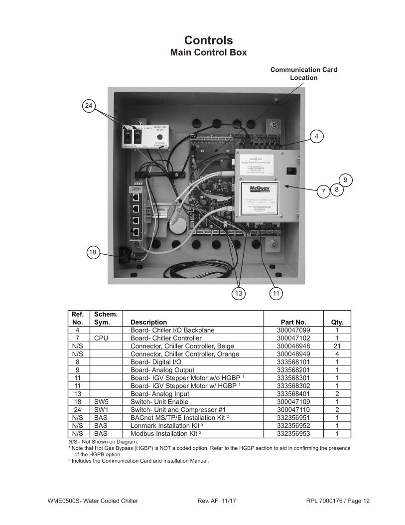
ControlsMain Control Box
13 11
24
18
4
7
98
Communication CardLocation
Ref. Schem. No. Sym. Description Part No. Qty. 4 Board- Chiller I/O Backplane 300047099 1 7 CPU Board- Chiller Controller 300047102 1 N/S Connector, Chiller Controller, Beige 300048948 21 N/S Connector, Chiller Controller, Orange 300048949 4 8 Board- Digital I/O 333568101 1 9 Board- Analog Output 333568201 1 11 Board- IGV Stepper Motor w/o HGBP 1 333568301 1 11 Board- IGV Stepper Motor w/ HGBP 1 333568302 1 13 Board- Analog Input 333568401 2 18 SW5 Switch- Unit Enable 300047109 1 24 SW1 Switch- Unit and Compressor #1 300047110 2 N/S BAS BACnet MS/TP/E Installation Kit 2 332356951 1 N/S BAS Lonmark Installation Kit 2 332356952 1 N/S BAS Modbus Installation Kit 2 332356953 1N/S= Not Shown on Diagram.1 Note that Hot Gas Bypass (HGBP) is NOT a coded option. Refer to the HGBP section to aid in confirming the presence
of the HGPB option.2 Includes the Communication Card and Installation Manual.

WME0500S- Water Cooled Chiller Rev. AF 11/17 RPL 7000176 / Page 13
Ref. Schem. No. Sym. Description Part No. Qty. 1 Fan 120 VAC 600 CFM 300047091 2 3 VFD1 VFD Chassis Assembly- Phases 1- 3 1 300047093 1 4 Fuse 20A/1000VAC 300047094 2 5A Valve- Solenoid 331796001 2 5B Valve- Coil 120/60, 10 watt 331796051 2 5C Repair Kit- Solenoid Valve 300052079 2 6 LR Line Reactor 3PH 300047096 2 7 IPS Intermediate Power Supply 300047097 1 8 MCB CBKR Molded Case 25KAIC 600V 400A 300048927 1 CBKR Molded Case 25KAIC 600V 600A 300048929 1 CBKR Molded Case 35KAIC 480V 500A 300047098 1 CBKR Molded Case 35KAIC 600V 500A 300047071 1 CBKR Molded Case 35KAIC 600V 600A 300047100 1 CBKR Molded Case 35KAIC 600V 800A 300048924 1 CBKR Molded Case 50KAIC 600V 400A 300048928 1 CBKR Molded Case 50KAIC 600V 600A 300048930 1 CBKR Molded Case 65KAIC 600V 500A 300047088 1 CBKR Molded Case 65KAIC 600V 600A 300047108 1 CBKR Molded Case 65KAIC 600V 800A 300048925 1 CBKR Molded Case 100KAIC 480V 400A 300047069 1 CBKR Molded Case 100KAIC 480V 600A 300048923 1 CBKR Molded Case 100KAIC 480V 800A 300048926 1 10 Surge Suppressor 480V 300047076 1 11 VFD1 VFD Chassis Assembly- Phases 4- 6 1, 2 300048873 1
Controls VFD Enclosure
1
3
4
5A
6
7
8
10
11
13
1 Refer to VFD Chassis Assembly detail on the following pages.2 This chassis is present ONLY when Code 04= M3.
5C 5B

WME0500S- Water Cooled Chiller Rev. AF 11/17 RPL 7000176 / Page 14
Controls VFD Chassis- Diagrams
1
5 6
2
8
1011
3
4
7
9
12 13 1314
15
15
16

WME0500S- Water Cooled Chiller Rev. AF 11/17 RPL 7000176 / Page 15
Controls VFD Chassis- Components & Compressor Wiring Harness
Ref. Schem. No. Sym. Description Part No. Qty. 1
1 Fuse 600A, 700V 300047092 3 2 VFD Controller Assembly 300048932 1 Backup Battery for VFD Controller 334295801 1 3 Voltage Transducer Interface Board 300048950 1 4 Link Capacitor 1200uF, 700V 300048939 3 5 Connector Interface 300048934 1 6 Q4- 6 Steering Bridge IGBT Assy. 300048937 3 7 Q1- 3 Chopper IGBT Assy. 300048936 3 8 TDM1- 3 Diode Thyristor Module 300049088 3 9 Fuse 20A, 800V 300048941 2 10 CT1- 3 Current Transducer 300048942 3 11 CT4- 6 Current Transducer 300048943 3 12 TS1 Thermal Switch 300048945 1 13 TH1, 2 Thermistor 300048944 2 14 R3, 4 Resistor 2K2, 75W 300049089 2 15 R1, 2 Resistor 150R, 250W 300048938 2 16 Wire Harness/Cable Kit 2 300055446 1 N/S L1- 3 Chopper Chokes/Inductors 300048952 3 N/S Thyristor Driver Board 300048933 1 N/S Snubber Board 300048935 1 N/S Snubber Capacitors 1uF, 1200V 300048940 6 N/S D1 Diode 300048951 1N/S= Not Shown on Diagram. 1 Quantity PER Chassis Assembly with the exception of chassis 300048873. VFD Chassis Assembly 300048873 has no
Controller (Ref. #2).2 Kit contains ribbon cables and harnesses. Connections include: Q1-J10; Q2-J11; Q3-J12; Q4-J7; Q5-J8; Q6-J9; J1-J6;
and J1-J14.
Compressor Wiring Harness
VFD Chassis- Components
2 The Wiring Harnesses are available as complete assemblies only.
Compressor Wiring Harness 331795501 2(12/11 & Earlier)
Compressor Wiring Harness 331795502 2(1/12 & Later)

WME0500S- Water Cooled Chiller Rev. AF 11/17 RPL 7000176 / Page 16
ControlsVFD Power Supply Plate- Diagram
19
20
11
18
17
222
21
14
16
14
15
13
5
9
6
37
48
1312

WME0500S- Water Cooled Chiller Rev. AF 11/17 RPL 7000176 / Page 17
ControlsVFD Power Supply Plate- Components
Ref. Schem. No. Sym. Description Part No. Qty. 2 Plate- Partition Gray 300047073 17 3 Terminal Block Gray 300047074 36 4 Terminal Block- Ground Green-Yellow 300047075 9 5 Bracket- End, Snap on 300047190 7 6 ELR Relay- Earth Leakage 300047078 1 7 CB1 Circuit Breaker- Primary 8A 300047079 1 8 CB2- 4 Circuit Breaker- 2 Fans & MCB trip 2A 300047080 3 9 Switch- Fan Failure 331578601 2 11 DC power supply +15 VDC 100 watts 300047081 1 12 DC power supply 15 VDC 25 watts 300047082 1 13 DC power supply +24 VDC 77 watts 300047083 2 14 DC power supply +24 VDC 100 watts 300047084 2 15 DC power supply +12 VDC 72 watts 300047085 1 16 DC Distribution Board 300047086 1 17 PM Monitor- Voltage, Power and Current 300047087 1 18 TX2 Transformer 480/240/120V 500VA 349939804 1 19 F1- 10 Fuse holder 300047088 7 20 F1-2, F8-10 Fuse 2A 300047089 2 21 F3- 5 Fuse 6A 300047090 3 22 F6-7 Fuse 10A 300046902 2

WME0500S- Water Cooled Chiller Rev. AF 11/17 RPL 7000176 / Page 18
ControlsOITS- Operator Interface Touch Screen and Rapid Restore
1 These parts are included with the LCD Support Arm Assembly. The mounting hardware (screws, washers and nuts) are also included and are not available separately.
2 In 9/2010 the color of the LCD Touchscreen and LCD support arm was changed from Beige to Black. Form, fit, and function are identical and parts can be substituted for each other.
15
Swivel Pins 1
Swivel Bracket 1
18
Main Control Box
16
20
Ref.No. Description Part No. Qty.
15 Monitor- 15" LCD Touchscreen 2
9/2010 and Before, Beige 330276501 1 10/2010 and Later, Black 330276502 1 16 LCD Support Arm Assembly 2 9/2010 and Before, Beige 330815401 1 10/2010 and Later, Black 330815411 1 18 OITS/Unit Control Box Support Block 330406501 2
20 Rapid Restore Kit (includes mounting brackets and hardware) 331585160 1

WME0500S- Water Cooled Chiller Rev. AF 11/17 RPL 7000176 / Page 19
Control Sensors087 (Rev. AAA) Impeller Units Sensor Location Diagrams
Top View
Front View
End View
Evaporator
Condenser
S09
S14
S15
S07
S12
S10 S11
In Out
In
Out
S08S05
S06
S04
S01
S02
S13
WME0500S- Water Cooled Chiller Rev. AF 11/17 RPL 7000176 / Page 20
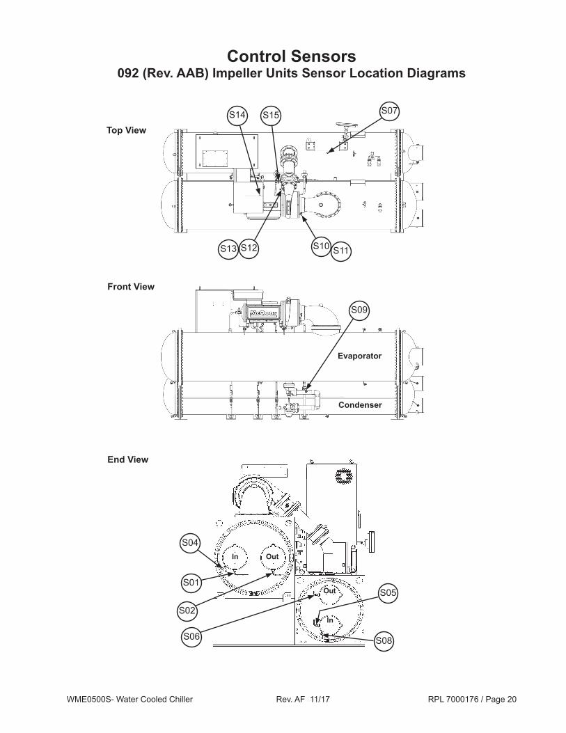
Control Sensors092 (Rev. AAB) Impeller Units Sensor Location Diagrams
In Out
In
Out
Top View
Front View
End View
Evaporator
Condenser
S09
S14 S15 S07
S10 S11
S08
S05
S06
S04
S01
S02
S12S13
WME0500S- Water Cooled Chiller Rev. AF 11/17 RPL 7000176 / Page 21
Ref. Description Part Qty. No. Number S01 Sensor- Evaporator Entering Water Temperature 073007203 1 S02 Sensor- Evaporator Leaving Water Temperature 073007203 1 S04 Switch- Evaporator Entering Flow 331796201 1 N/S Cable- Evaporator Entering Flow Switch (5 Meter Lg.) 330571402 1 S05 Sensor- Condenser Entering Water Temperature 073007203 1 S06 Sensor- Condenser Leaving Water Temperature 073007203 1 S08 Switch- Condenser Entering Flow 331796201 1 N/S Cable- Condenser Entering Flow Switch (5 Meter Lg.) 330571402 1 S09 Sensor- Liquid Line Temperature 073007203 1 S10 Sensor- Compressor Suction Temperature 331795201 1, 2 1 S12 Sensor- Compressor Discharge Temperature 331795201 1, 2 1 S14 Sensor- Motor Gap Temperature 331795205 2 1 S15 Switch- High Pressure 074796301 1
Control SensorsComponents
N/S= Not Shown on Diagram.1 Early production units used sensor 331795205. This sensor is 6.0" OAL. P/N 331795201 is 4.38" OAL. Confirm which sensor is required
before ordering.2 The Cable for this Sensor is part of the Compressor Wiring Harness and is NOT available separately. Refer to the Compressor Wiring
Harness section for harness p/ns.
Ref. Description Part Qty. No. Number Transducers for units built through August 2017 * S11 Transducer- Low Pressure 071568521 1
S07, S13 Transducer- High Pressure 071568621 2
N/S Cable for Transducers, 10 ft. (includes Boot) 074667501 3 N/S Cable for Transducers, 16 ft. (includes Boot) 074667502 3 N/S Cable for Transducers, 20 ft. (includes Boot) 074667503 3 N/S Cable for Transducers, 25 ft. (includes Boot) 074667504 3
N/S Boot for Transducer Cable (black) 071583301 3
Transducers for units built beginning September 2017 * S11 Transducer- Low Pressure 333992031 1
S07, S13 Transducer- High Pressure 333992032 2
N/S Cable for Transducers, 10 ft. (includes Boot) 910217971 3 N/S Cable for Transducers, 16 ft. (includes Boot) 910217972 3 N/S Cable for Transducers, 20 ft. (includes Boot) 910217973 3 N/S Cable for Transducers, 25 ft. (includes Boot) 910217974 3
N/S Boot for Transducer Cable (blue) 335657201 3
N/S = Not Shown on diagram* For units built in August 2017, check the color of the Transducer Cable Boot. If Boot is black, use the parts above for “through August 2017”. If Boot is blue, use the parts above for “beginning September 2017”.
WME0500S- Water Cooled Chiller Rev. AF 11/17 RPL 7000176 / Page 22
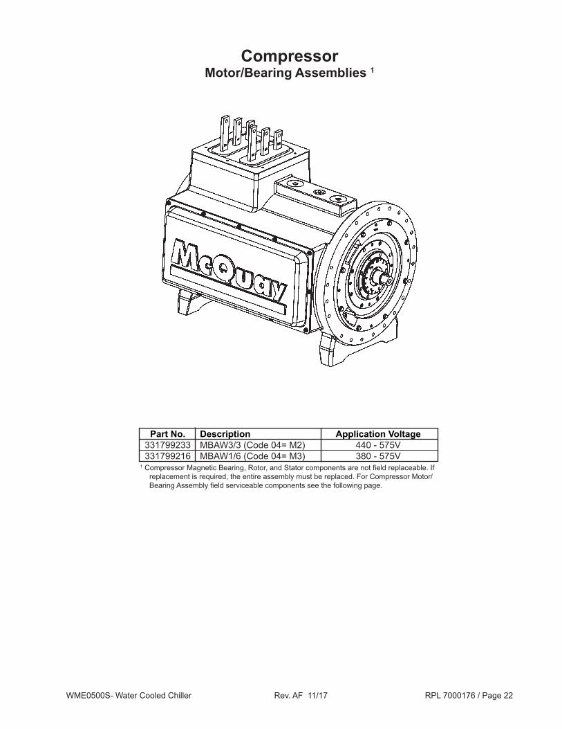
Compressor Motor/Bearing Assemblies 1
Part No. Description Application Voltage 331799233 MBAW3/3 (Code 04= M2) 440 - 575V 331799216 MBAW1/6 (Code 04= M3) 380 - 575V 1 Compressor Magnetic Bearing, Rotor, and Stator components are not field replaceable. If
replacement is required, the entire assembly must be replaced. For Compressor Motor/Bearing Assembly field serviceable components see the following page.
WME0500S- Water Cooled Chiller Rev. AF 11/17 RPL 7000176 / Page 23
Front View Bottom View
Back View
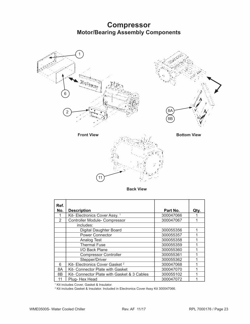
CompressorMotor/Bearing Assembly Components
8A2
1
6
11
Ref. No. Description Part No. Qty. 1 Kit- Electronics Cover Assy. 1 300047066 1 2 Controller Module- Compressor 300047067 1 includes: Digital Daughter Board 300055356 1 Power Connector 300055357 1 Analog Test 300055358 1 Thermal Fuse 300055359 1 I/O Back Plane 300055360 1 Compressor Controller 300055361 1 Stepper/Driver 300055362 1 6 Kit- Electronics Cover Gasket 2 300047068 1 8A Kit- Connector Plate with Gasket 300047070 1 8B Kit- Connector Plate with Gasket & 3 Cables 300055102 1 11 Plug- Hex Head 300047072 11 Kit includes Cover, Gasket & Insulator.2 Kit includes Gasket & Insulator. Included in Electronics Cover Assy Kit 300047066.
8B

WME0500S- Water Cooled Chiller Rev. AF 11/17 RPL 7000176 / Page 24
Compressor087 Impeller- (Compressor Revision/Code 07= AAA)
Impeller Assembly
Ref. No. Description Part No. Qty. 402 Impeller Assembly 1 331347201 1 410 Volute Insert 331350904 1 411 Pin- Volute, Roll .094 x .50" 735038039 3 412 Pin- Volute, Dowel .312 x 1.125" 735038026 1 413 O-Ring 2 070194999 1
402
410
413
412
411
1 Available as an assembly only.2 Included in Compressor O-Ring Kit p/n 300049072.

WME0500S- Water Cooled Chiller Rev. AF 11/17 RPL 7000176 / Page 25
Compressor087 Impeller- (Compressor Revision/Code 07= AAA)
Impeller Seal & Compressor Fittings- Diagrams
602
502504
503
505
506507
508
603 604
605
606
607
WME0500S- Water Cooled Chiller Rev. AF 11/17 RPL 7000176 / Page 26
Compressor087 Impeller- (Compressor Revision/Code 07= AAA)Impeller Seal & Compressor Fittings- Components
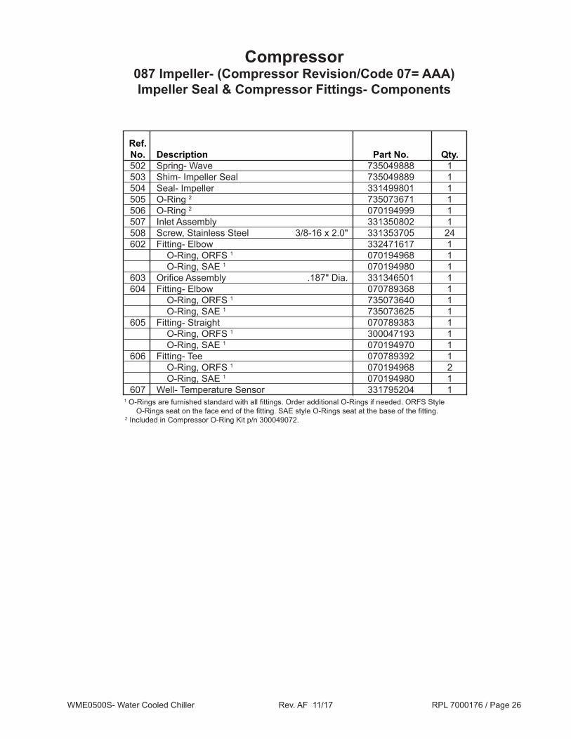
Ref. No. Description Part No. Qty. 502 Spring- Wave 735049888 1 503 Shim- Impeller Seal 735049889 1 504 Seal- Impeller 331499801 1 505 O-Ring 2 735073671 1 506 O-Ring 2 070194999 1 507 Inlet Assembly 331350802 1 508 Screw, Stainless Steel 3/8-16 x 2.0" 331353705 24 602 Fitting- Elbow 332471617 1 O-Ring, ORFS 1 070194968 1 O-Ring, SAE 1 070194980 1 603 Orifice Assembly .187" Dia. 331346501 1 604 Fitting- Elbow 070789368 1 O-Ring, ORFS 1 735073640 1 O-Ring, SAE 1 735073625 1 605 Fitting- Straight 070789383 1 O-Ring, ORFS 1 300047193 1 O-Ring, SAE 1 070194970 1 606 Fitting- Tee 070789392 1 O-Ring, ORFS 1 070194968 2 O-Ring, SAE 1 070194980 1 607 Well- Temperature Sensor 331795204 11 O-Rings are furnished standard with all fittings. Order additional O-Rings if needed. ORFS Style
O-Rings seat on the face end of the fitting. SAE style O-Rings seat at the base of the fitting.2 Included in Compressor O-Ring Kit p/n 300049072.

WME0500S- Water Cooled Chiller Rev. AF 11/17 RPL 7000176 / Page 27
Compressor087 Impeller- (Compressor Revision/Code 07= AAA)
Discharge Housing & High Speed Shaft Seal
Ref. No. Description Part No. Qty. 302 Discharge Housing 331351004 1 303 O-Ring 1 070194978 1 304 Screw, Stainless Steel #.38-16 x 2.0" 331353705 12 305 Screw, Stainless Steel #.38-16 x 3.0" 331353706 6 306 Ring- Liquid Injection 331353401 1 307 Screw #10 x .50" 735034921 12 311 Pin .50 x .09" 735038039 1 312 Seal- High Speed Shaft 1.5" 331351101 1 313 Shim- High Speed Shaft Seal 331347501 1 314 Spring- Wave, High Speed Shaft 735049886 1 315 Retainer- High Speed Shaft Seal 331353301 1 509 Valve- Access 070229306 1
302
303
304
305
509
306
307
307
311
312314
313
315
1 Included in Compressor O-Ring Kit p/n 300049072.
WME0500S- Water Cooled Chiller Rev. AF 11/17 RPL 7000176 / Page 28
Compressor087 Impeller- (Compressor Revision/Code 07= AAA)
Inlet Assembly- Diagrams
221
219
220
201
201
202
203
205
204
206
208
209210
211
212213
218
219
207

WME0500S- Water Cooled Chiller Rev. AF 11/17 RPL 7000176 / Page 29
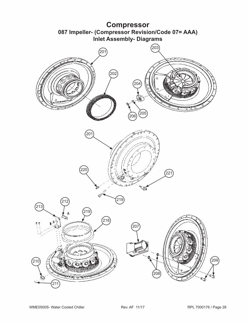
Compressor087 Impeller- (Compressor Revision/Code 07= AAA)
Inlet Assembly- Components
Ref. Description Part Qty. No. Number 201 Inlet Housing 331351202 1 202 Gear- Face 331352301 1 203 Inlet Vane 331352601 11 204 Gear- Spur 331352401 11 205 Key- Spur Gear .188 x .50" 735023804 11 206 Ring- Retaining Spur Gear 735049890 11 207 IGV Actuator Assembly, Complete 331350801 1 208 O-Ring 1 070194996 2 209 Screw- Stainless Steel .50-13 x 1.50" 331353704 2 210 Plug- Sensor Magnet 331353501 1 211 Magnet 331353802 1 212 Sensor 331352831 1 213 Bracket- Sensor 331352701 1 218 Ring- Vane Stop 331352901 1 219 Well- Temperature Sensor 331795202 1 220 Valve- Acess 070229306 1 221 Connector- Male 8 Pole 331795401 11 Included in Compressor O-Ring Kit p/n 300049072.

WME0500S- Water Cooled Chiller Rev. AF 11/17 RPL 7000176 / Page 30
Compressor092 Impeller- (Compressor Revision/Code 07= AAB)
Impeller Assembly
Ref. No. Description Part No. Qty. 402 Washer- Impeller 735043467 1 403- 406 Kit- Shim Washers, Impeller 1 300049084 1 407 Impeller Assembly 2 331347202 1 415 Volute Insert 331498002 1 416 Pin- Volute Insert .50 x .09" 735038039 1 417 O-Ring 3 330198639 1 418 Ring- Retaining 735049893 1
402 403
405
404
406
415
416
418
417
407
1 The shim combination is unique to each compressor. The kit contains quantities of four shim sizes.2 Available as an assembly only.3 Included in Compressor O-Ring Kit p/n 300049071.

WME0500S- Water Cooled Chiller Rev. AF 11/17 RPL 7000176 / Page 31
Compressor092 Impeller- (Compressor Revision/Code 07= AAB)
Impeller Seal & Compressor Fittings- Diagrams
506
609
608
607606
605
602
505
504
503
502
604
603
WME0500S- Water Cooled Chiller Rev. AF 11/17 RPL 7000176 / Page 32
Compressor092 Impeller- (Compressor Revision/Code 07= AAB) Impeller Seal & Compressor Fittings- Components
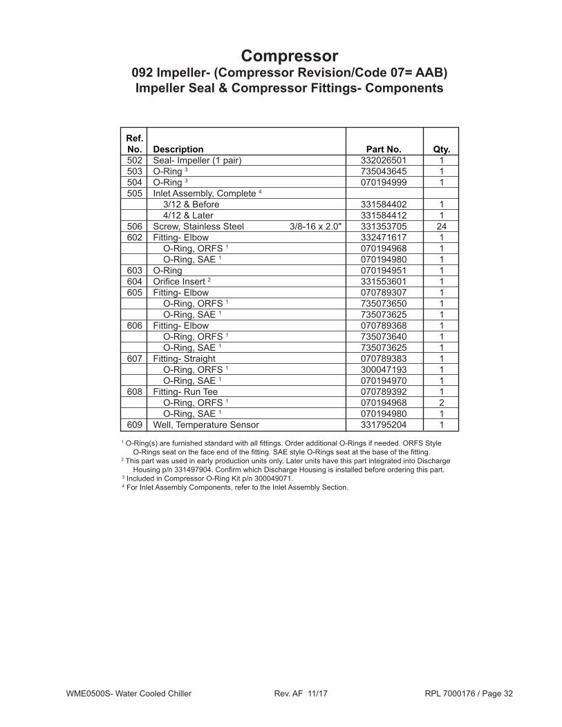
Ref. No. Description Part No. Qty. 502 Seal- Impeller (1 pair) 332026501 1 503 O-Ring 3 735043645 1 504 O-Ring 3 070194999 1 505 Inlet Assembly, Complete 4 3/12 & Before 331584402 1 4/12 & Later 331584412 1 506 Screw, Stainless Steel 3/8-16 x 2.0" 331353705 24 602 Fitting- Elbow 332471617 1 O-Ring, ORFS 1 070194968 1 O-Ring, SAE 1 070194980 1 603 O-Ring 070194951 1 604 Orifice Insert 2 331553601 1 605 Fitting- Elbow 070789307 1 O-Ring, ORFS 1 735073650 1 O-Ring, SAE 1 735073625 1 606 Fitting- Elbow 070789368 1 O-Ring, ORFS 1 735073640 1 O-Ring, SAE 1 735073625 1 607 Fitting- Straight 070789383 1 O-Ring, ORFS 1 300047193 1 O-Ring, SAE 1 070194970 1 608 Fitting- Run Tee 070789392 1 O-Ring, ORFS 1 070194968 2 O-Ring, SAE 1 070194980 1 609 Well, Temperature Sensor 331795204 1
1 O-Ring(s) are furnished standard with all fittings. Order additional O-Rings if needed. ORFS Style O-Rings seat on the face end of the fitting. SAE style O-Rings seat at the base of the fitting.
2 This part was used in early production units only. Later units have this part integrated into Discharge Housing p/n 331497904. Confirm which Discharge Housing is installed before ordering this part.
3 Included in Compressor O-Ring Kit p/n 300049071.4 For Inlet Assembly Components, refer to the Inlet Assembly Section.

WME0500S- Water Cooled Chiller Rev. AF 11/17 RPL 7000176 / Page 33
Compressor092 Impeller- (Compressor Revision/Code 07= AAB)
Discharge Housing & High Speed Shaft Seal
Ref. No. Description Part No. Qty. 302 Discharge Housing 331497902 1 1 Discharge Housing 331497904 1 303 O-Ring 2 070194978 1 304 Screw, Stainless Steel #.38-16 x 2.0" 331353705 12 305 Screw, Stainless Steel #.38-16 x 3.0" 331353706 6 306 Ring- Liquid Injection 331583901 1 307 Screw #10 x .50" 735034921 12 311 Pin .50 x .09" 735038039 1 312 Seal- High Speed Shaft 1.5" 331351101 1 313 Shim- High Speed Shaft Seal 331347501 1 314 Spring- Wave, High Speed Shaft 735049886 1 315 Retainer- High Speed Shaft Seal 331353301 1 316 Pin- Locator 331584501 1 508 Valve- Access 070229306 1
302
303
304
305
508
306
307
307
311
312314
313
315
316
1 This part was used in early production units only. This housing uses a separate Orifice Insert p/n 331553601. Later units use Discharge Housing p/n 331497904 which has the Orifice integrated into the housing. Confirm which Discharge Housing is installed before ordering this part.
2 Included in Compressor O-Ring Kit p/n 300049071.

WME0500S- Water Cooled Chiller Rev. AF 11/17 RPL 7000176 / Page 34
Compressor092 Impeller- (Compressor Revision/Code 07= AAB)
Inlet Assembly- Diagrams
221
222
220
201
201
202
203
205
204
206
208
209210
211
212213
218
219
207

WME0500S- Water Cooled Chiller Rev. AF 11/17 RPL 7000176 / Page 35
Compressor092 Impeller- (Compressor Revision/Code 07= AAB)
Inlet Assembly- Components
Ref. Description Part Qty. No. Number 201 Inlet Housing 331583702 1 202 Gear- Face 2 3/12 & Before 331352301 1 4/12 & Later 331438301 1 203 Inlet Vane 331352602 11 204 Gear- Spur 2
3/12 & Before 331352402 11 4/12 & Later 331438202 11 205 Pin- Spur Gear .313 x .58" 735038065 11 206 Ring- Retaining Spur Gear 735049890 11 207 IGV Actuator Assembly, Complete 331584401 1 208 O-Ring 1 070194996 2 209 Screw- Stainless Steel .50-13 x 1.50" 331353704 2 210 Plug- Sensor Magnet 2
3/12 & Before 331353501 1 4/12 & Later 331438401 1 211 Magnet 331353802 1 212 Sensor 331352831 1 213 Bracket- Sensor 331352701 1 218 Ring- Vane Stop 2 3/12 & Before 331352901 1 4/12 & Later 331438101 1 219 Ring- Retaining Vane Stop 735049892 1 220 Valve- Acess 070229306 1 221 Connector- Male 8 Pole 331795401 1 222 Well- Temperature Sensor 331795202 11 Included in Compressor O-Ring Kit p/n 300049071.2 Old and new parts are NOT interchangeable. If original parts are NOT available, ALL footnote #2 noted
parts must be replaced.
WME0500S- Water Cooled Chiller Rev. AF 11/17 RPL 7000176 / Page 36
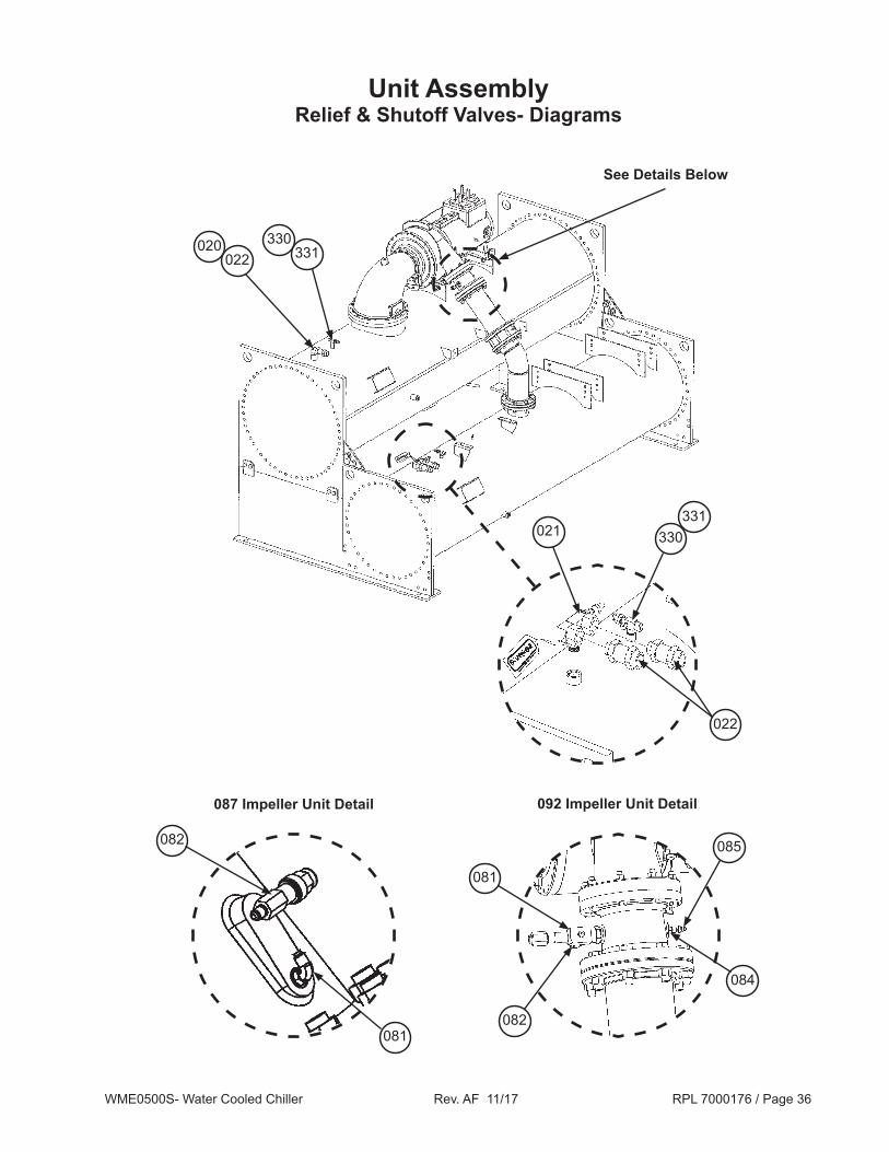
Unit AssemblyRelief & Shutoff Valves- Diagrams
See Details Below
087 Impeller Unit Detail 092 Impeller Unit Detail
022020
022
021
331330
331330
081
082
081
082
084
085

WME0500S- Water Cooled Chiller Rev. AF 11/17 RPL 7000176 / Page 37
Unit AssemblyRelief & Shutoff Valves- Components
Ref. No. Description Part No. Qty. 020 Fitting- 90 Degree Street Elbow, 087 Impeller 735031239 1 020 Fitting- 90 Degree Elbow, 092 Impeller 332471635 1 O-Ring 1 070194963 1 021 Valve- Shut Off 3 735039964 1 O-Ring, SAE 1 070194980 1 022 Valve- Relief 200# 735045817 3 081 Fitting- 90 Degree Elbow 087 Impeller 735043923 1 O-Ring 1 735073623 1 081 Valve- Angle 092 Impeller 332471751 1 082 Valve- Shut Off 087 Impeller 735039947 1 082 Cap- Tube End 092 Impeller 070789347 1 084 Fitting 735043930 1 O-Ring 1 070194948 1 085 Fitting- Swivel 735043954 1 330 Valve- Shut Off 2 2
331 Cap- Shut Off Valve 2 2
1 O-Ring(s) are furnished standard with all fittings. Order additional O-Rings if needed. ORFS Style O-Rings seat on the face end of the fitting. SAE style O-Rings seat at the base of the fitting.
2 Refer to the Condenser and Evaporator sections for p/ns and quantities.3 The original valve design used on units built 1/11 and before used a straight valve and a 90 Degree elbow fitting.
This valve arrangement was replaced starting 2/11 with a 90 degree valve that does not require an elbow fitting. When replacing an original design valve, the elbow fitting is removed, and then the listed 90 degree valve is a direct replacement.

WME0500S- Water Cooled Chiller Rev. AF 11/17 RPL 7000176 / Page 38
Unit AssemblyDischarge Piping Stack- Diagrams
087 Impeller Unit DetailShell Stack 36/30 1
092 Impeller Unit DetailShell Stack 30/26 & 36/30 1
125
126
126
125
126
126
128 129
135
132
129 134
126022 138
022 128135
132
022 138
1 Shell Stack is the combined values of the diameter of the Evaporator and the Condenser Vessels. Eg.: 36/30 indicates that the unit has a 36" diameter Evaporator and a 30" diameter Condenser.
126
126

WME0500S- Water Cooled Chiller Rev. AF 11/17 RPL 7000176 / Page 39
Unit AssemblyDischarge Piping Stack- Components
Ref. No. Description Part No. Qty. 125 Valve- Check 10.0" 332507003 1 126 Gasket 070199039 3 128 Screw .88 x 7.0" 735034167 12 129 Nut 735029609 24 132 Elbow- 90 Degree 10.0" 735031364 1 134 Screw .88 x 3.5" 735034165 12 135 Nozzle- Discharge 331587802 1
087 Impeller Unit Detail- Shell Stack 36/30
092 Impeller Unit Detail- Shell Stack 30/26 & 36/30
Ref. No. Description Part No. Qty. 022 Nut 735029626 24 125 Valve- Check 6.0" Until 03/11 332507004 1 03/11 & Later 332630204 1 126 Gasket 070199039 4 128 Screw .75 x 6.0" 735033972 8 132 Elbow- 90 Degree 6.0" 073222107 1 135 Nozzle- Discharge 331583802 1 138 Bolt 3/4-10 x 3.25" 735033966 16
WME0500S- Water Cooled Chiller Rev. AF 11/17 RPL 7000176 / Page 40
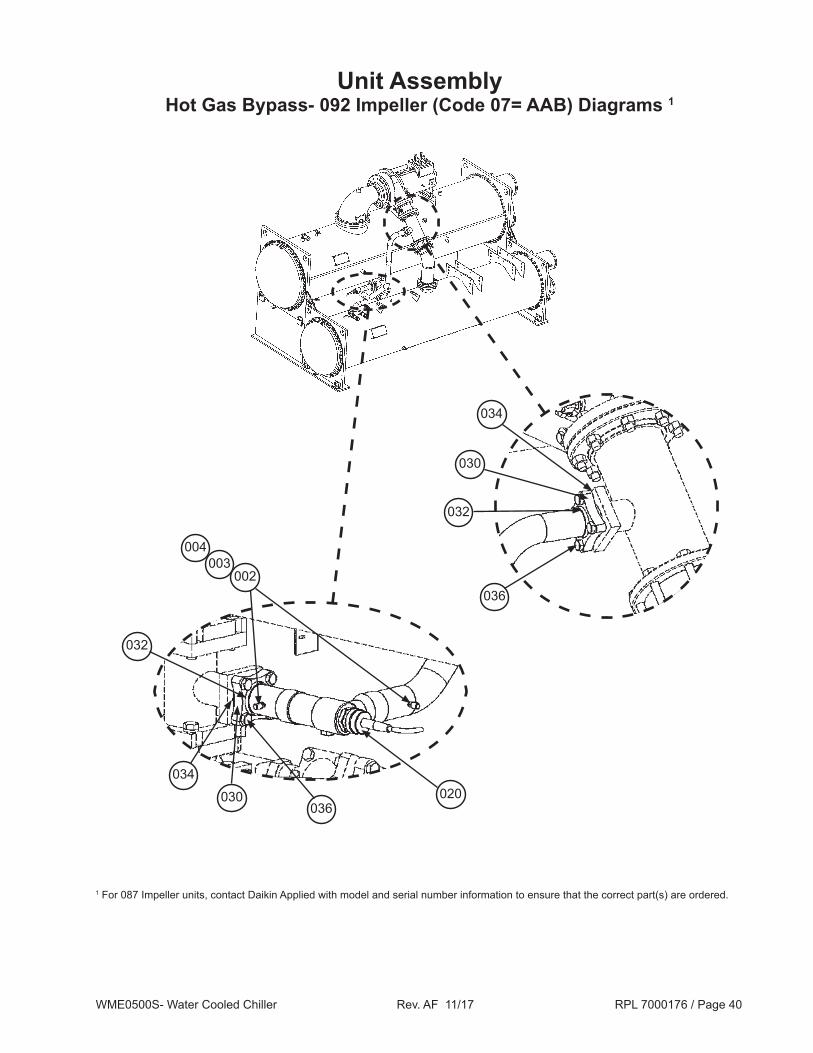
Unit AssemblyHot Gas Bypass- 092 Impeller (Code 07= AAB) Diagrams 1
1 For 087 Impeller units, contact Daikin Applied with model and serial number information to ensure that the correct part(s) are ordered.
002003
004
034
032
030
020030
034
032
036
036

WME0500S- Water Cooled Chiller Rev. AF 11/17 RPL 7000176 / Page 41
Unit AssemblyHot Gas Bypass- 092 Impeller (Code 07= AAB) Components 1
Ref. No. Description Part No. Qty. 002 Core- Schrader Valve 026541100 2 003 Valve- Schrader 071100801 2 004 Cap- Schrader Valve 032943500 2 020 Valve- Expansion 250T 330386205 1 Motor- Expansion Valve 330386209 1 Sight Glass- Expansion Valve 300043182 1 030 Kit- Flange 2 735016403 2 032 Adapter 735049702 2 034 Gasket- Flange 2 070199112 2 036 Screw- Flange 2 .62 x 2.50" 735033864 8
1 For 087 Impeller units, contact Daikin Applied with model and serial number information to ensure that the correct part(s) are ordered.
Hot Gas Bypass- 092 Impeller (Code 07= AAB) Components
Hot Gas Bypass- 092 Impeller (Code 07= AAB) Kits
Ref. No. Description Part No. Qty. N/S Kit, Hot Gas Bypass 3
Shell Stack 30/26 333378001 1 Shell Stack 36/30 333378003 1N/S= Not shown on diagram.3 The Hot Gas Bypass Kit is designed to ADD Hot Gas Bypass capability to a unit. Common
replacement parts for these kits are listed in the above table. Note that Hot Gas Bypass is NOT a coded option. Visual inspection of the unit is required to confirm the presence of the Hot Gas Bypass option.
2 The Flange Kit does NOT contain a gasket. If a gasket is required, order Gasket- Flange Ref # 034 p/n 070199112. Also, DO NOT use the screws that come with this Flange Kit. If screws are required, order 4pc. of Screw- Flange Ref # 036 p/n 735033864.

WME0500S- Water Cooled Chiller Rev. AF 11/17 RPL 7000176 / Page 42
Unit AssemblySuction Piping- 087 Impeller (Code 07= AAA)
Ref. No. Description Part No. Qty. 084 Screw .37 x 2.0" 735036512 18 085 Screw- Stainless Steel .38 -16 x 1.75" 331353707 20 086 O-Ring 1 070194992 1 087 O-Ring 1 350233017 1 088 Elbow- Suction 90 Degree 331352002 1 136 O-Ring 735073645 1
136085088
085
084
087
086
1 Included in Compressor O-Ring Kit p/n 300049071.

WME0500S- Water Cooled Chiller Rev. AF 11/17 RPL 7000176 / Page 43
Ref. No. Description Part No. Qty. 084 Screw .37 x 2.0" 735036512 18 085 Screw- Stainless Steel .38 -16 x 1.75" 331353707 12 086 Elbow- Suction 90 Degree 331352002 1 087 O-Ring 1 070194992 1 088 O-Ring 1 350233017 1 092 Screw .50 x 3.0" 735033852 8 093 Washer 040500310 8 094 Nut 735029625 8 136 O-Ring 735073620 1
Unit AssemblySuction Piping- 092 Impeller (Code 07= AAB)
088
086
087085
084
136
094
092 093
1 Included in Compressor O-Ring Kit p/n 300049071.

WME0500S- Water Cooled Chiller Rev. AF 11/17 RPL 7000176 / Page 44
Unit AssemblyLiquid Injection
Ref. No. Description Part No. Qty. 002 Core- Schrader Valve 026541100 1 003 Valve- Schrader 071100801 1 004 Cap- Schrader Valve 032943500 1 021 Fitting- ORFS to Braze Sleeve 070789351 1 O-Ring 1 070194968 1 022 Nut- Braze Sleeve 070789354 1 027 Valve- Solenoid 1.375" 331796004 1 N/S Coil- Solenoid Valve 24VDC 331796054 1 029 Strainer 735030536 1 031 Valve- Ball 1.375" 330286006 1
027
029
031
002 003
004
022021
1 O-Ring(s) are furnished standard with each fitting. Order additional O-Rings if needed. ORFS Style O-Rings seat on the face end of the fitting. SAE style O-Rings seat at the base of the fitting.
WME0500S- Water Cooled Chiller Rev. AF 11/17 RPL 7000176 / Page 45
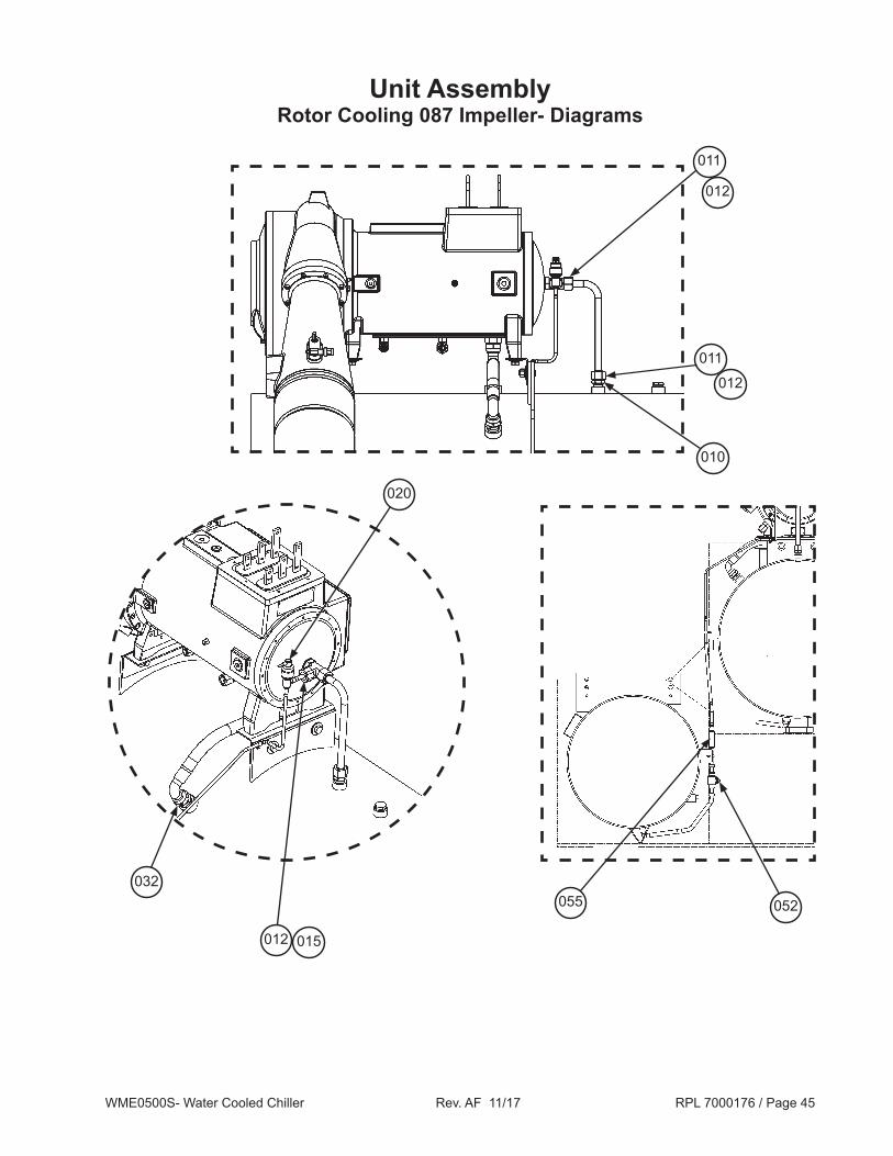
Unit AssemblyRotor Cooling 087 Impeller- Diagrams
010
011
012
011
012
012 015
020
032
052055

WME0500S- Water Cooled Chiller Rev. AF 11/17 RPL 7000176 / Page 46
Unit AssemblyRotor Cooling 087 Impeller- Components
Ref. Description Part Qty. No. Number 010 Fitting- MP to ORFS 070789381 1 O-Ring 1 070194968 1 011 Fitting- ORFS to Braze Sleeve 070789351 2 O-Ring 1 070194968 2 012 Nut- Braze Sleeve 070789354 3 015 Fitting- ORFS to Reducer Sleeve 070789391 1 O-Ring 1 070194968 1 020 Valve- Solenoid 331796003 1 032 Fitting- MP to ORFS 070789382 1 O-Ring 1 300047193 1 052 Valve- Ball .875" 330286004 1 055 Strainer 735030501 11 O-Ring(s) are furnished standard with each fitting. Order additional O-Rings if needed. ORFS Style
O-Rings seat on the face end of the fitting. SAE style O-Rings seat at the base of the fitting.

WME0500S- Water Cooled Chiller Rev. AF 11/17 RPL 7000176 / Page 47
Unit AssemblyRotor Cooling 092 Impeller- Diagrams
010
011
012
011
012
012 015
020
032

WME0500S- Water Cooled Chiller Rev. AF 11/17 RPL 7000176 / Page 48
Unit AssemblyRotor Cooling 092 Impeller- Diagrams, Continued
002 003
004
052 055
064
062060
063

WME0500S- Water Cooled Chiller Rev. AF 11/17 RPL 7000176 / Page 49
Ref. Description Part Qty. No. Number 002 Core- Schrader Valve 026541100 1 003 Valve- Schrader 071100801 1 004 Cap- Schrader Valve 032943500 1 010 Fitting- ORFS to SAE 070789350 1 O-Ring, ORFS 1 070194968 1 O-Ring, SAE 1 070194980 1 011 Fitting- ORFS to Braze Sleeve 070789351 2 O-Ring 1 070194968 2 012 Nut- Braze Sleeve 070789354 3 015 Fitting- Reducer Sleeve 070789391 1 O-Ring 1 070194968 1 020 Valve- Solenoid 331796003 1 032 Fitting- MP to ORFS 070789383 1 O-Ring, ORFS 1 300047193 1 O-Ring, SAE 1 070194970 1 052 Valve- Ball .875" 330286004 1 055 Strainer 735030501 1 060 Valve- Ball .375" 330286001 1 062 Fitting- Nut 070789310 1 O-Ring, ORFS 1 735073650 1 063 Fitting- ORFS Braze Sleeve 332471636 1 O-Ring, ORFS 1 735073640 1 064 Fitting- ORFS Braze Socket 332471619 1 O-Ring, ORFS 1 735073640 1
Unit AssemblyRotor Cooling 092 Impeller- Components
1 O-Ring(s) are furnished standard with each fitting. Order additional O-Rings if needed. ORFS Style O-Rings seat on the face end of the fitting. SAE style O-Rings seat at the base of the fitting.

WME0500S- Water Cooled Chiller Rev. AF 11/17 RPL 7000176 / Page 50
Unit AssemblyStator Cooling 087 Impeller- Diagrams
Stator Cooling Return Section Piping Detail
Stator Cooling Supply Section Piping Detail
028
026
022
023
020
045
046
045
052
046
030
036
002 003
004045
046
002 003
004
029

WME0500S- Water Cooled Chiller Rev. AF 11/17 RPL 7000176 / Page 51
Unit AssemblyStator Cooling 087 Impeller- Components
Ref. Description Part Qty. No. Number 002 Core- Schrader Valve 026541100 2 003 Valve- Schrader 071100801 2 004 Cap- Schrader Valve 032943500 2 020 Fitting- Male Elbow to SAE 070789356 1 O-Ring, SAE 1 070194980 1 022 Fitting- ORFS to Braze Sleeve 070789351 1 O-Ring 1 070194968 1 023 Nut- Braze Sleeve 070789354 1 026 Valve- Solenoid 331796002 1 028 Fitting- Sleeve ORFS 070789361 1 O-Ring, ORFS 1 735073640 1 029 Fitting- Nut 070789360 1 030 Filter Drier 735028828 1 036 Valve- Ball .625" 330286003 1 045 Fitting- ORFS to Braze Sleeve 070789316 3 O-Ring, ORFS 1 735073650 3 046 Fitting- Nut ORFS 070789310 3 O-Ring, ORFS 1 735073650 3 052 Valve- Ball .875" 330286004 11 O-Ring(s) are furnished standard with each fitting. Order additional O-Rings if needed. ORFS Style
O-Rings seat on the face end of the fitting. SAE style O-Rings seat at the base of the fitting.

WME0500S- Water Cooled Chiller Rev. AF 11/17 RPL 7000176 / Page 52
Unit AssemblyStator Cooling 092 Impeller- Diagrams
Stator Cooling Return Section Piping Detail
Stator Cooling Supply Section Piping Detail
028
026
022
023
020
045
046
045
052
046
030
036
002 003
004045
046
002 003
004
029
WME0500S- Water Cooled Chiller Rev. AF 11/17 RPL 7000176 / Page 53
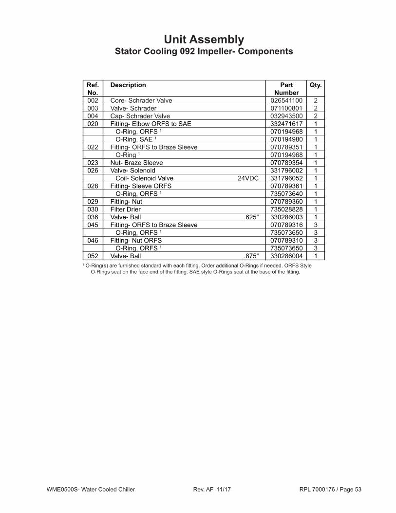
Unit AssemblyStator Cooling 092 Impeller- Components
Ref. Description Part Qty. No. Number 002 Core- Schrader Valve 026541100 2 003 Valve- Schrader 071100801 2 004 Cap- Schrader Valve 032943500 2 020 Fitting- Elbow ORFS to SAE 332471617 1 O-Ring, ORFS 1 070194968 1 O-Ring, SAE 1 070194980 1 022 Fitting- ORFS to Braze Sleeve 070789351 1 O-Ring 1 070194968 1 023 Nut- Braze Sleeve 070789354 1 026 Valve- Solenoid 331796002 1 Coil- Solenoid Valve 24VDC 331796052 1 028 Fitting- Sleeve ORFS 070789361 1 O-Ring, ORFS 1 735073640 1 029 Fitting- Nut 070789360 1 030 Filter Drier 735028828 1 036 Valve- Ball .625" 330286003 1 045 Fitting- ORFS to Braze Sleeve 070789316 3 O-Ring, ORFS 1 735073650 3 046 Fitting- Nut ORFS 070789310 3 O-Ring, ORFS 1 735073650 3 052 Valve- Ball .875" 330286004 11 O-Ring(s) are furnished standard with each fitting. Order additional O-Rings if needed. ORFS Style
O-Rings seat on the face end of the fitting. SAE style O-Rings seat at the base of the fitting.

WME0500S- Water Cooled Chiller Rev. AF 11/17 RPL 7000176 / Page 54
Unit AssemblyVFD Cooling
021 022
002 003
004
018
012
021 022 012
Ref. Description Part Qty. No. Number 002 Core- Schrader Valve 026541100 1 003 Valve- Schrader 071100801 1 004 Cap- Schrader Valve 032943500 1 012 Valve- Ball .875" 330286004 2 018 Strainer 735030501 1 021 Fitting- ORFS to Braze Sleeve 070789351 2 O-Ring 1 070194968 2 022 Nut- Braze Sleeve 070789354 21 O-Ring(s) are furnished standard with each fitting. Order additional O-Rings if needed. ORFS Style
O-Rings seat on the face end of the fitting. SAE style O-Rings seat at the base of the fitting.

WME0500S- Water Cooled Chiller Rev. AF 11/17 RPL 7000176 / Page 55
Unit AssemblyLiquid Line- Diagrams
See Detail Below
140A
100
101
020 022
024021 023
080 082 081
140C
140B
060A060B
060E060D060C
251 253252

WME0500S- Water Cooled Chiller Rev. AF 11/17 RPL 7000176 / Page 56
Unit AssemblyLiquid Line- Components
Ref. Description Part Qty. No. Number 020 Coupling- Adapter 070760902 1 021 Flange 071992101 1 022 Gasket 735073402 1 023 Screw .75 x 3.5" 735033967 4 024 Strainer 070977801 1 060A Saddle- Sight Glass 330743304 1 060B Cap- Sight Glass 330508701 1 060C Valve- Schrader 071100801 1 060D Core- Schrader Valve 026541100 1 060E Cap- Schrader Valve 032943500 1 080 Flange 070761402 1 081 Screw .625 x 2.50" 735033864 4 082 O-Ring 735043674 1 100 O-Ring 735073633 1 101 Screw .75 x 2.50" 735033877 4 140A Expansion Valve- Body 650Ton 331861602 1 140B Expansion Valve- Actuator 330386209 2 140C Expansion Valve- Sight Glass .875" 015997817 2 251 Valve- Shut Off 3.0" 735039807 1 252 Screw .625 x 5.5" 735033958 4 253 Gasket- Shut Off Valve 070199104 1

WME0500S- Water Cooled Chiller Rev. AF 11/17 RPL 7000176 / Page 57
CondenserDiagrams
351 352350 355
331330
331330
331330
351 352
26" & 30" Condenser 092 ImpellerRear View
30" Condenser 087 ImpellerRear View
350 355 353 354
353 354
353 354353 354
(Located on the Front Sideof the Condenser)
110A
110A
Water Box Head Option
251
251
366
352
252253
252253
WME0500S- Water Cooled Chiller Rev. AF 11/17 RPL 7000176 / Page 58
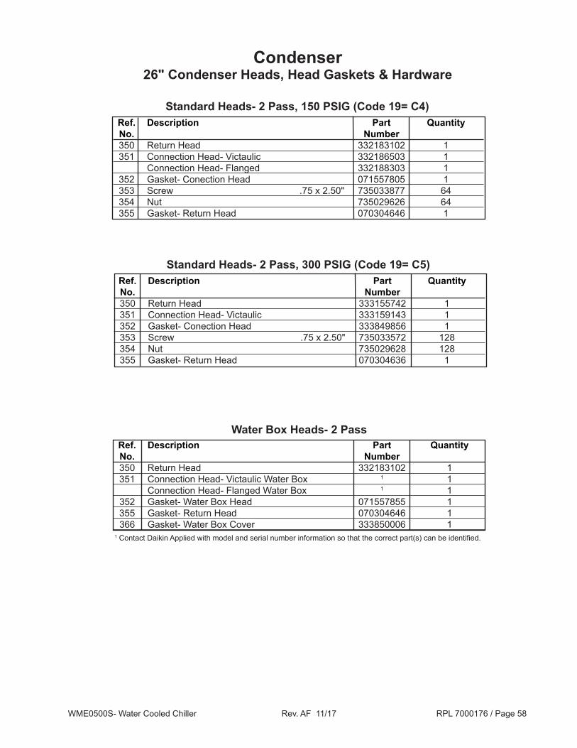
Ref. Description Part Quantity No. Number 350 Return Head 332183102 1 351 Connection Head- Victaulic 332186503 1 Connection Head- Flanged 332188303 1 352 Gasket- Conection Head 071557805 1 353 Screw .75 x 2.50" 735033877 64 354 Nut 735029626 64 355 Gasket- Return Head 070304646 1
Condenser26" Condenser Heads, Head Gaskets & Hardware
Standard Heads- 2 Pass, 150 PSIG (Code 19= C4)
Water Box Heads- 2 Pass Ref. Description Part Quantity No. Number 350 Return Head 332183102 1 351 Connection Head- Victaulic Water Box 1 1 Connection Head- Flanged Water Box 1 1 352 Gasket- Water Box Head 071557855 1 355 Gasket- Return Head 070304646 1 366 Gasket- Water Box Cover 333850006 11 Contact Daikin Applied with model and serial number information so that the correct part(s) can be identified.
Ref. Description Part Quantity No. Number 350 Return Head 333155742 1 351 Connection Head- Victaulic 333159143 1 352 Gasket- Conection Head 333849856 1 353 Screw .75 x 2.50" 735033572 128 354 Nut 735029628 128 355 Gasket- Return Head 070304636 1
Standard Heads- 2 Pass, 300 PSIG (Code 19= C5)

WME0500S- Water Cooled Chiller Rev. AF 11/17 RPL 7000176 / Page 59
Condenser26" Condenser Heads, Head Gaskets & Hardware, Continued
Ref. Description Part Quantity No. Number 351 Connection Head- Victaulic Water Inlet 331156904 1 Connection Head- Victaulic Water Outlet 331156905 1 Connection Head- Flanged Water Inlet 331158704 1 Connection Head- Flanged Water Outlet 331158705 1 352 Gasket- Head 071557805 2 353 Screw .75 x 2.50" 735033877 64 354 Nut 735029626 64
Standard Heads- 3 Pass
Water Box Heads- 3 Pass Ref. Description Part Quantity No. Number 351 Connection Head- Victaulic Water Inlet 1 2 Connection Head- Victaulic Water Outlet 1 2 Connection Head- Flanged Water Inlet 1 2 Connection Head- Flanged Water Outlet 1 2 352 Gasket- Water Box Head 071557855 2 355 Gasket- Return Head 070304646 2 366 Gasket- Water Box Cover 333850006 21 Contact Daikin Applied with model and serial number information so that the correct part(s) can be identified.

WME0500S- Water Cooled Chiller Rev. AF 11/17 RPL 7000176 / Page 60
Condenser30" Condenser Heads, Head Gaskets & Hardware
Ref. Description Part Quantity No. Number 350 Return Head 332183302 1 351 Connection Head- Victaulic 332186703 1 Connection Head- Flanged 332188503 1 352 Gasket- Conection Head 071557806 1 353 Screw .75 x 3.00" 735033878 80 354 Nut 735029626 80 355 Gasket- Return Head 070304621 1
Standard Heads- 2 Pass
Water Box Heads- 2 Pass Ref. Description Part Quantity No. Number 350 Return Head 332183302 1 351 Connection Head- Victaulic Water Box 1 1 Connection Head- Flanged Water Box 1 1 352 Gasket- Water Box Head 071557871 1 355 Gasket- Return Head 070304621 1 366 Gasket- Water Box Cover 333850007 11 Contact Daikin Applied with model and serial number information so that the correct part(s) can be identified.

WME0500S- Water Cooled Chiller Rev. AF 11/17 RPL 7000176 / Page 61
Condenser30" Condenser Heads, Head Gaskets & Hardware, Continued
Ref. Description Part Quantity No. Number 351 Connection Head- Victaulic Water Inlet 331157104 1 Connection Head- Victaulic Water Outlet 331157105 1 Connection Head- Flanged Water Inlet 331158904 1 Connection Head- Flanged Water Outlet 331158905 1 352 Gasket- Head 071557806 2 353 Screw .75 x 3.00" 735033878 80 354 Nut 735029626 80
Standard Heads- 3 Pass
Water Box Heads- 3 Pass Ref. Description Part Quantity No. Number 351 Connection Head- Victaulic Water Box 1 2 Connection Head- Flanged Water Box 1 2 352 Gasket- Water Box Head 071557871 2 355 Gasket- Return Head 070304621 2 366 Gasket- Water Box Cover 333850007 21 Contact Daikin Applied with model and serial number information so that the correct part(s) can be identified.

WME0500S- Water Cooled Chiller Rev. AF 11/17 RPL 7000176 / Page 62
Code 17 Wall Type & Part (2nd digit) Thickness Material Number L .025 Turbo CSL, Cu 330441408 N .028 Turbo CSL, Cu 330441425 P .035 Turbo CSL, Cu 073238577
Tube Table 1
CondenserTube Counts, Tubes, Sight Glass, Shut Off Valve & Gasket,
Charge Valve & Cap
Ref. Description Part Qty. No. Number 110A Sight Glass 1.0" MPT 350229501 1 251 Valve- Shut Off (King Valve) 3.0" 735039807 1 252 Screw .625 x 5.5" 735033958 4 253 Gasket- Shut Off Valve 070199104 1 330 Valve- Charge (Code 7= AAA, 087 Impeller) 735039929 1 Valve- Charge (Code 7= AAB, 092 Impeller) 332480201 2 331 Cap- Charge Valve 073243901 1 or 2
Sight Glass, Shut Off Valve & Gasket, Charge Valve & Cap
Tube CountsFor Tube counts see the Nomenclature Model Number- Complete section.
1 For Tubes not listed, contact Daikin Applied with model and serial number information so that the correct tube(s) can be identified.

WME0500S- Water Cooled Chiller Rev. AF 11/17 RPL 7000176 / Page 63
EvaporatorDiagrams
331330
26" & 30" Evaporator 092 ImpellerRear View
30" Evaporator 087 ImpellerRear View
(Located on the Front Sideof the Evaporator)
110A
331330
331330
331330
350 355353 354
350 355353 354
110A
353 354
353 354
352351
352351
Water Box Head Option
366
352351

WME0500S- Water Cooled Chiller Rev. AF 11/17 RPL 7000176 / Page 64
Evaporator30" Evaporator Heads, Head Gaskets & Hardware
Ref. Description Part Quantity No. Number 350 Return Head 332183302 1 351 Connection Head- Victaulic 332183303 1 Connection Head- Flanged 332184903 1 352 Gasket- Conection Head 071557806 1 353 Screw .75 x 3.00" 735033878 80 354 Nut 735029626 80 355 Gasket- Return Head 070304621 1
Standard Heads- 2 Pass
Water Box Heads- 2 Pass Ref. Description Part Quantity No. Number 350 Return Head 332183302 1 351 Connection Head- Victaulic Water Box 1 1 Connection Head- Flanged Water Box 1 1 352 Gasket- Water Box Head 350296771 1 355 Gasket- Return Head 070304621 1 366 Gasket- Water Box Cover 333850007 11 Contact Daikin Applied with model and serial number information so that the correct part(s) can be identified.

WME0500S- Water Cooled Chiller Rev. AF 11/17 RPL 7000176 / Page 65
Evaporator30" Evaporator Heads, Head Gaskets & Hardware, Continued
Ref. Description Part Quantity No. Number 351 Connection Head- Victaulic 331153704 2 Connection Head- Flanged 331155304 2 352 Gasket- Head 071557806 2 353 Screw .75 x 3.00" 735033878 80 354 Nut 735029626 80
Standard Heads- 3 Pass
Water Box Heads- 3 Pass Ref. Description Part Quantity No. Number 351 Connection Head- Victaulic 1 2 Connection Head- Flanged 1 2 352 Gasket- Water Box Head 350296771 2 366 Gasket- Water Box Cover 333850007 21 Contact Daikin Applied with model and serial number information so that the correct part(s) can be identified.
WME0500S- Water Cooled Chiller Rev. AF 11/17 RPL 7000176 / Page 66
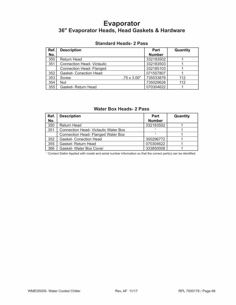
Evaporator36" Evaporator Heads, Head Gaskets & Hardware
Ref. Description Part Quantity No. Number 350 Return Head 332183502 1 351 Connection Head- Victaulic 332183503 1 Connection Head- Flanged 332185103 1 352 Gasket- Conection Head 071557807 1 353 Screw .75 x 3.00" 735033878 112 354 Nut 735029626 112 355 Gasket- Return Head 070304622 1
Standard Heads- 2 Pass
Water Box Heads- 2 Pass Ref. Description Part Quantity No. Number 350 Return Head 332183502 1 351 Connection Head- Victaulic Water Box 1 1 Connection Head- Flanged Water Box 1 1 352 Gasket- Conection Head 350296772 1 355 Gasket- Return Head 070304622 1 366 Gasket- Water Box Cover 333850008 11 Contact Daikin Applied with model and serial number information so that the correct part(s) can be identified.

WME0500S- Water Cooled Chiller Rev. AF 11/17 RPL 7000176 / Page 67
Evaporator36" Evaporator Heads, Head Gaskets & Hardware, Continued
Ref. Description Part Quantity No. Number 351 Connection Head- Victaulic 331153904 2 Connection Head- Flanged 331155504 2 352 Gasket- Head 071557807 2 353 Screw .75 x 3.00" 735033878 112 354 Nut 735029626 112
Standard Heads- 3 Pass
Water Box Heads- 3 Pass Ref. Description Part Quantity No. Number 351 Connection Head- Victaulic 1 2 Connection Head- Flanged 1 2 352 Gasket- Water Box Head 350296772 2 366 Gasket- Water Box Cover 333850008 21 Contact Daikin Applied with model and serial number information so that the correct part(s) can be identified.

WME0500S- Water Cooled Chiller Rev. AF 11/17 RPL 7000176 / Page 68
EvaporatorTubes, Tube Counts, Sight Glass, Charge Valve & Cap
Ref. Description Part Qty. No. Number 110A Sight Glass 1.0" MPT 350229501 1 330 Valve- Charge (Code 7= AAA, 087 Impeller) 735039929 2 Valve- Charge (Code 7= AAB, 092 Impeller) 332480201 2 331 Cap- Charge Valve 073243901 2
Sight Glass, Charge Valve & Cap
Code 09 Wall Type & Part (2nd digit) Thickness Material Number E .025 Turbo EHP, Cu 073238590 F .028 Turbo EHP, Cu 330441418 Q .035 Turbo EHP, Cu 330441414
Tube Table 1
Tube CountsFor Tube counts see the Nomenclature Model Number- Complete section.
1 For Tubes not listed, contact Daikin Applied with model and serial number information so that the correct tube(s) can be identified.

Critical Daikin Applied OEM PartsAre What Your HVAC Unit Needs!
Daikin MagnitudeTM Centrifugal ChillerDaikin McQuay MagnitudeTM Centrifugal Chiller
McQuay MagnitudeTM Centrifugal ChillerWME0500
Critical Components UNIT SIZE Voltage Part Number
Sensors S01 - Evap Entering Water Temp 0500 ALL 073007203 S02 - Evap Leaving Water Temp 0500 ALL 073007203S05 - Cond Entering Water Temp 0500 ALL 073007203S06 - Cond Leaving Water Temp 0500 ALL 073007203S07, S13 - High Pressure Transducer (thru Aug. 2017) 0500 ALL 071568621S07, S13 - High Pressure Transducer (beginning Sept. 2017) 0500 ALL 333992032S09 - Liquid Line Temp 0500 ALL 073007203
S10 - Compr Suction Temp, 4.38" length * 0500 ALL 331795201 S10 - Compr Suction Temp, 6.0" length * 0500 ALL 331795205 S11 - Low Pressure Transducer (thru Aug. 2017) 0500 ALL 071568521 S11 - Low Pressure Transducer (beginning Sept. 2017) 0500 ALL 333992031S12 - Compr Discharge Temp, 4.38" length * 0500 ALL 331795201S12 - Compr Discharge Temp, 6.0" length * 0500 ALL 331795205S14 - Motor Gap Temp 0500 ALL 331795205
*6.0" used in early production units. Confirm size before ordering.
Switches S04 - Switch, Evap Entering Flow 0500 ALL 331796201
S08 - Switch, Cond Entering Flow 0500 ALL 331796201 S15 - Switch, High Pressure 0500 ALL 074796301 VFD Controls Wire Harness/Cable Kit 0500 ALL 300055446 Fuse, 20A/1000VAC 0500 ALL 300047094 Fuse, 600A/700V 0500 ALL 300047092 Fuse, 20A/800V 0500 ALL 300048941 Fuse, Power Supply Plate F1-2, F8-10 0500 ALL 300047089 Fuse, Power Supply Plate F3-5 0500 ALL 300047090 Fuse, Power Supply Plate F6-7 0500 ALL 300046902
Compressor O-Ring Kit Compressor O-Ring Kit 0500 ALL 300049071
7000176 Rev. AE 11/2017 CPL Page 1 of 1
Call Your Local Daikin Applied Parts Distributor For All Your Parts Needs.To Locate A Distributor, Go To www.DaikinApplied.com or Call 1-800-37PARTS