
McQuay WME - Magnitude Magnetic Bearing Centrifugal · PDF fileCatalog 604-3 Magnitude™...
42
Catalog 604-3 Magnitude™ Magnetic Bearing Centrifugal Chiller Model WME 400 to 700 tons (1400 to 2461 kW) 3/60/460 HFC-134a
Transcript of McQuay WME - Magnitude Magnetic Bearing Centrifugal · PDF fileCatalog 604-3 Magnitude™...
Catalog 604-3
Magnitude™ Magnetic Bearing Centrifugal ChillerModel WME400 to 700 tons (1400 to 2461 kW)3/60/460HFC-134a
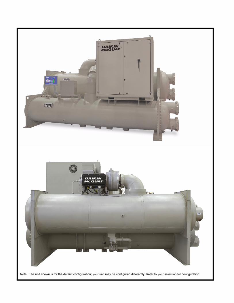
Note: The unit shown is for the default configuration; your unit may be configured differently. Refer to your selection for configuration.
Contents
Features and Benefits . . . . . . . . . . . . . . . . . . . . . . . 4Technology That Just Makes Sense . . . . . . . . 4The Compressor Technology . . . . . . . . . . . . . 5Oil-Free Design Benefits . . . . . . . . . . . . . . . . . 5Unit Control Features. . . . . . . . . . . . . . . . . . . . 6IPLV/NPLV Defined . . . . . . . . . . . . . . . . . . . . . 6Quality Standards . . . . . . . . . . . . . . . . . . . . . . 7
Chiller Identification. . . . . . . . . . . . . . . . . . . . . . . . . 8Electrical Data . . . . . . . . . . . . . . . . . . . . . . . . . . . . 10
Electrical Notes . . . . . . . . . . . . . . . . . . . . . . . 10Field Wiring Diagram . . . . . . . . . . . . . . . . . . . . . . . 11Dimension Drawings . . . . . . . . . . . . . . . . . . . . . . . 12
Drawing Notes . . . . . . . . . . . . . . . . . . . . . . . . 12Standard Head Connection Dimensions . . . . 23
Marine Water Box Dimensions . . . . . . . . . . . 24Optional External Harmonic Filter Dimensions 25
Physical Data & Weights. . . . . . . . . . . . . . . . . . . . 27Lifting and Mounting Weights . . . . . . . . . . . . 27Physical Data - Evaporator . . . . . . . . . . . . . . 28Physical Data - Condenser . . . . . . . . . . . . . . 28
Refrigeration Diagram. . . . . . . . . . . . . . . . . . . . . . 29Application Considerations . . . . . . . . . . . . . . . . . 30
Location Requirements . . . . . . . . . . . . . . . . . 30Optimum Water Temperatures and Flow . . . 30Condenser Water Temperature. . . . . . . . . . . 31Retrofit Knockdown . . . . . . . . . . . . . . . . . . . . 32
Options and Accessories . . . . . . . . . . . . . . . . . . . 33Engineering Guide Specifications . . . . . . . . . . . . 35
Document: CAT 604-3Original Issue: October 2009Revision Issue: July 2012Replaces: May 2012Software Version: MST Centrifugal Chiller v. 08.0
©2012 McQuay International. Illustrations and data cover the Daikin McQuay product at the time of publication and we reserve the right to make changes in design and construction at anytime without notice. ™® The following are trademarks or registered trademarks of their respective companies: BACnet from ASHRAE; LONMARK, LonTalk, LONWORKS, and the LONMARK logo are managed, granted and used by LONMARK International under a license granted by Echelon Corporation; Modbus from Schneider Electric; MicroTech E, Open Choices from McQuay International; LEED from the U.S. Green Building Council.
Manufactured in an ISO-certified facility
Features and Benefits
Features and BenefitsTechnology That Just Makes Sense
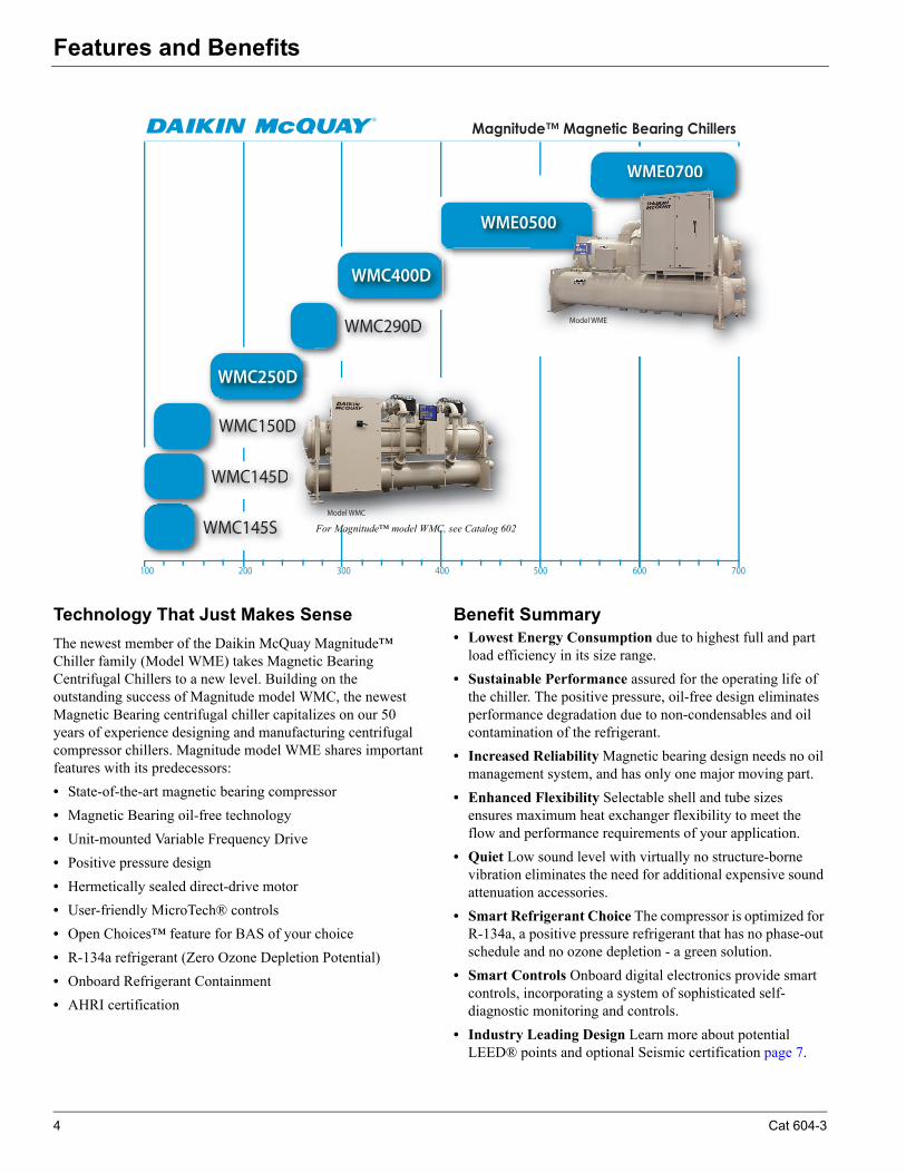
The newest member of the Daikin McQuay Magnitude™ Chiller family (Model WME) takes Magnetic Bearing Centrifugal Chillers to a new level. Building on the outstanding success of Magnitude model WMC, the newest Magnetic Bearing centrifugal chiller capitalizes on our 50 years of experience designing and manufacturing centrifugal compressor chillers. Magnitude model WME shares important features with its predecessors:
• State-of-the-art magnetic bearing compressor
• Magnetic Bearing oil-free technology
• Unit-mounted Variable Frequency Drive
• Positive pressure design
• Hermetically sealed direct-drive motor
• User-friendly MicroTech® controls
• Open Choices™ feature for BAS of your choice
• R-134a refrigerant (Zero Ozone Depletion Potential)
• Onboard Refrigerant Containment
• AHRI certification
Benefit Summary• Lowest Energy Consumption due to highest full and part
load efficiency in its size range.
• Sustainable Performance assured for the operating life of the chiller. The positive pressure, oil-free design eliminates performance degradation due to non-condensables and oil contamination of the refrigerant.
• Increased Reliability Magnetic bearing design needs no oil management system, and has only one major moving part.
• Enhanced Flexibility Selectable shell and tube sizes ensures maximum heat exchanger flexibility to meet the flow and performance requirements of your application.
• Quiet Low sound level with virtually no structure-borne vibration eliminates the need for additional expensive sound attenuation accessories.
• Smart Refrigerant Choice The compressor is optimized for R-134a, a positive pressure refrigerant that has no phase-out schedule and no ozone depletion - a green solution.
• Smart Controls Onboard digital electronics provide smart controls, incorporating a system of sophisticated self-diagnostic monitoring and controls.
• Industry Leading Design Learn more about potential LEED® points and optional Seismic certification page 7.
100 200 300 400 500 600 700
Magnitude™ Magnetic Bearing Chillers
WME0700
WMC145S
WMC400D
WMC290D
WMC250D
WMC150D
WMC145D
WME0500
D
D
D
Model WMC
WME0700
500
Model WME
For Magnitude™ model WMC, see Catalog 602
4 Cat 604-3
Features and Benefits
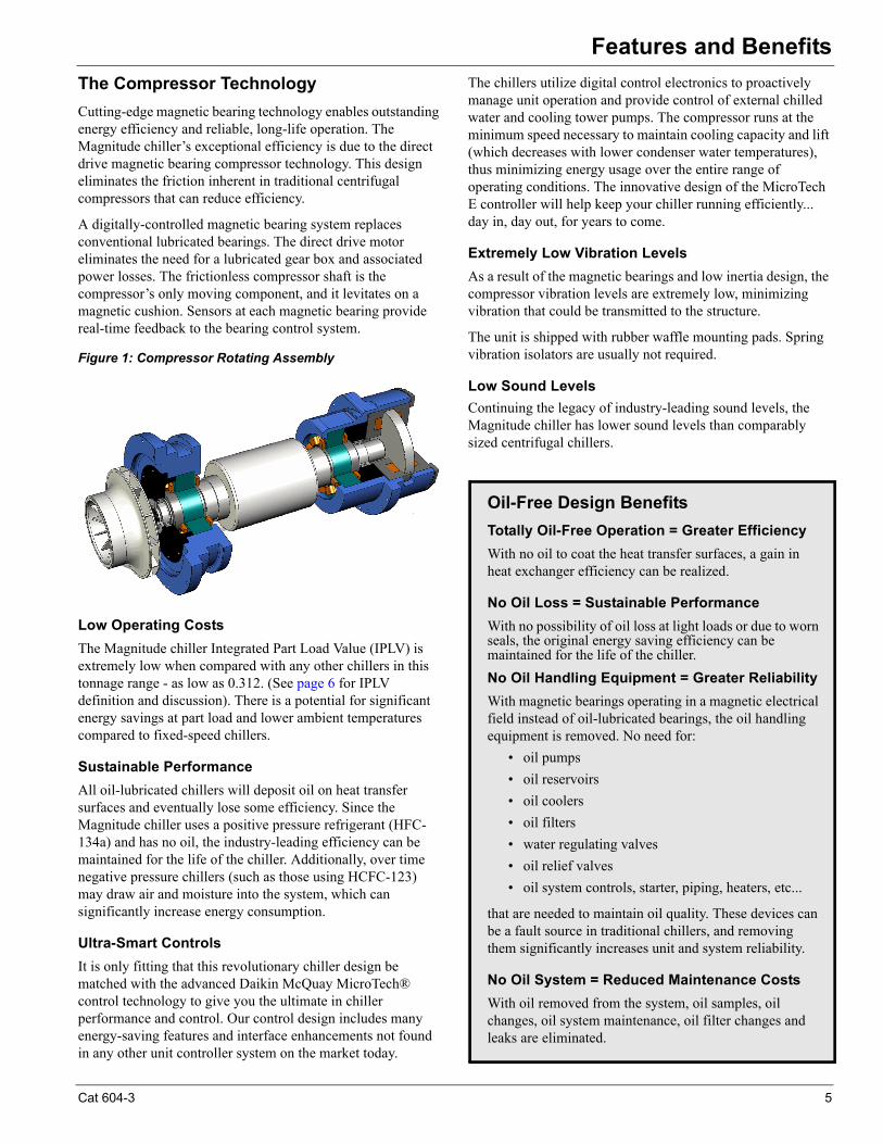
The Compressor Technology
Cutting-edge magnetic bearing technology enables outstanding energy efficiency and reliable, long-life operation. The Magnitude chiller’s exceptional efficiency is due to the direct drive magnetic bearing compressor technology. This design eliminates the friction inherent in traditional centrifugal compressors that can reduce efficiency.
A digitally-controlled magnetic bearing system replaces conventional lubricated bearings. The direct drive motor eliminates the need for a lubricated gear box and associated power losses. The frictionless compressor shaft is the compressor’s only moving component, and it levitates on a magnetic cushion. Sensors at each magnetic bearing provide real-time feedback to the bearing control system.
Figure 1: Compressor Rotating Assembly
Low Operating Costs
The Magnitude chiller Integrated Part Load Value (IPLV) is extremely low when compared with any other chillers in this tonnage range - as low as 0.312. (See page 6 for IPLV definition and discussion). There is a potential for significant energy savings at part load and lower ambient temperatures compared to fixed-speed chillers.
Sustainable Performance
All oil-lubricated chillers will deposit oil on heat transfer surfaces and eventually lose some efficiency. Since the Magnitude chiller uses a positive pressure refrigerant (HFC-134a) and has no oil, the industry-leading efficiency can be maintained for the life of the chiller. Additionally, over time negative pressure chillers (such as those using HCFC-123) may draw air and moisture into the system, which can significantly increase energy consumption.
Ultra-Smart Controls
It is only fitting that this revolutionary chiller design be matched with the advanced Daikin McQuay MicroTech® control technology to give you the ultimate in chiller performance and control. Our control design includes many energy-saving features and interface enhancements not found in any other unit controller system on the market today.
The chillers utilize digital control electronics to proactively manage unit operation and provide control of external chilled water and cooling tower pumps. The compressor runs at the minimum speed necessary to maintain cooling capacity and lift (which decreases with lower condenser water temperatures), thus minimizing energy usage over the entire range of operating conditions. The innovative design of the MicroTech E controller will help keep your chiller running efficiently... day in, day out, for years to come.
Extremely Low Vibration Levels
As a result of the magnetic bearings and low inertia design, the compressor vibration levels are extremely low, minimizing vibration that could be transmitted to the structure.
The unit is shipped with rubber waffle mounting pads. Spring vibration isolators are usually not required.
Low Sound Levels
Continuing the legacy of industry-leading sound levels, the Magnitude chiller has lower sound levels than comparably sized centrifugal chillers.
Oil-Free Design Benefits
Totally Oil-Free Operation = Greater Efficiency
With no oil to coat the heat transfer surfaces, a gain in heat exchanger efficiency can be realized.
No Oil Loss = Sustainable Performance
With no possibility of oil loss at light loads or due to worn seals, the original energy saving efficiency can be maintained for the life of the chiller.
No Oil Handling Equipment = Greater Reliability
With magnetic bearings operating in a magnetic electrical field instead of oil-lubricated bearings, the oil handling equipment is removed. No need for:
• oil pumps
• oil reservoirs
• oil coolers
• oil filters
• water regulating valves
• oil relief valves
• oil system controls, starter, piping, heaters, etc...
that are needed to maintain oil quality. These devices can be a fault source in traditional chillers, and removing them significantly increases unit and system reliability.
No Oil System = Reduced Maintenance Costs
With oil removed from the system, oil samples, oil changes, oil system maintenance, oil filter changes and leaks are eliminated.
Cat 604-3 5
Features and Benefits
Open Choices™ BAS Flexibility
The exclusive Open Choices feature provides seamless integration and comprehensive monitoring, control, and two-way data exchange using industry standard protocols LonTalk®, BACnet™ or Modbus™. Open Choices offers simple and inexpensive flexibility to use the Building Automation System of your choice without an expensive gateway panel. Open Choice Benefits include:
• Easy to integrate into your BAS of choice
• Factory- or field-installed communications module
• Integrated control logic for factory options
• Easy-to-use local user interface
• Comprehensive data exchange
Compliance with ASHRAE Std. 90.1
According to ASHRAE, chillers usually spend 99% of their operating hours at part load conditions and most of this time at less than 60% of design capacity. Thus, the part load efficiency of chillers is all-important.
ASHRAE Standard 90.1 was developed to assist owners and designers make informed choices on a buildings design, systems and equipment selection. Magnitude chillers can significantly exceed ASHRAE 90.1 minimum efficiency requirements.
Integrated Variable Frequency Drives
A Variable Frequency Drive (VFD) modulates compressor speed in response to load and evaporator/condenser pressure. VFD technology significantly reduces power input at part load operation and at lower than design ambient temperatures.
The VFD can dramatically reduce annual energy costs when there are long periods of part load operation and/or low compressor lift (lower condenser water temperatures). The attributes of VFD drives produce one of the industry's most efficient single-compressor chillers based on the all-important IPLV value. See IPLV/NPLV Defined inset for details on the AHRI IPLV efficiency rating.
An additional benefit of a VFD is improved power factors. The power factor will be 95% at 500 tons (AHRI conditions) with the M3 low harmonic option, and 91% for the M2 standard VFD (at 500 tons), which may help reduce power costs.
The use of a VFD on centrifugal chillers also provides an excellent method of reducing motor starting inrush-even better than “solid state” starters. Starting current can be closely controlled since both the frequency and voltage are regulated. This can be an important benefit to a building's electrical distribution system. Low inrush current at startup is also ideal for operation with backup or emergency power systems and can reduce the size of backup generators.
Optional Harmonic Filter
An optional factory-mounted and wired or field mounted and wired, passive harmonic filter is available for the WME 500. Although the harmonic characteristics of the standard VFD drive are acceptable in the vast majority of applications, this filter is a cost effective option for those applications that require reduced harmonics. Under most application conditions, it is guaranteed to meet the IEEE Standard 519 for harmonic levels.
Onboard Refrigerant Containment System
Pumpout systems are required on many jobs to collect and contain the refrigerant charge when access to internal chiller components is required for service. Magnitude condensers are designed to hold the entire unit refrigerant charge (<90% full and at 90°F (32°C) ambient temperature). When service is required, the refrigerant charge can be pumped down into the condenser by compressor operation and use of a refrigerant transfer unit. Elimination of the cost and space requirements of an external storage tank is a significant Daikin McQuay advantage.
Unit Control FeaturesThe Magnitude chiller control system consists of three major components: the unit control panel and the operator interface panel and the VFD power panel. The touch screen panel is on an adjustable arm so that it can be positioned comfortably for the operator. The control panel contains a USB port for downloading the unit's fault history, major parameter trends, and unit operating manual that is stored in memory.
IPLV/NPLV Defined
Part load performance can be presented in terms of Integrated Part Load Value (IPLV), which is based on AHRI standard rating conditions (listed above), or Non-Standard Part Load Values (NPLV), which is based on specified or job site conditions. IPLV and NPLV are based on the following weighting equation from AHRI 550/590:
Using kW/ton, where:A = kW/ton (or COP) at 100%B = kW/ton (or COP) at 75%C = kW/ton (or COP) at 50%D = kW/ton (or COP) at 25%
Weighting
The percent of annual ton-hours of operation near the four rated load points are as follows:
• 1% of operating ton-hours in the bin range 93~100% load (represented by the rating at 100% load)
• 42% of operating ton-hours in the bin range 62~92% load (represented by the rating at 75% load)
• 45% of operating ton-hours in the bin range 37~61% load (represented by the rating at 50% load)
• 12% of operating ton-hours in the bin range 0~36% load (represented by the rating at 25% load)
DCBA
IPLVorNPLV12.0
+45.0
+42.0
+01.0
1=
6 Cat 604-3
Features and Benefits
By constantly monitoring chiller status and real time data, the MicroTech E controller will automatically take proactive measures to relieve abnormal conditions or shut the unit down if a fault occurs. For example, if a problem occurs in the cooling tower and discharge pressure starts to rise, the controller will automatically hold the load point and activate an alarm signal. A further rise in pressure will initiate compressor unloading in an effort to stay online. If the pressure continues to rise, the unit will shut off as a safety feature.
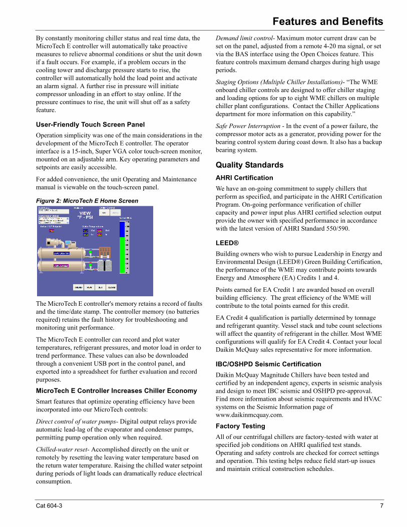
User-Friendly Touch Screen Panel
Operation simplicity was one of the main considerations in the development of the MicroTech E controller. The operator interface is a 15-inch, Super VGA color touch-screen monitor, mounted on an adjustable arm. Key operating parameters and setpoints are easily accessible.
For added convenience, the unit Operating and Maintenance manual is viewable on the touch-screen panel.
Figure 2: MicroTech E Home Screen
The MicroTech E controller's memory retains a record of faults and the time/date stamp. The controller memory (no batteries required) retains the fault history for troubleshooting and monitoring unit performance.
The MicroTech E controller can record and plot water temperatures, refrigerant pressures, and motor load in order to trend performance. These values can also be downloaded through a convenient USB port in the control panel, and exported into a spreadsheet for further evaluation and record purposes.
MicroTech E Controller Increases Chiller Economy
Smart features that optimize operating efficiency have been incorporated into our MicroTech controls:
Direct control of water pumps- Digital output relays provide automatic lead-lag of the evaporator and condenser pumps, permitting pump operation only when required.
Chilled-water reset- Accomplished directly on the unit or remotely by resetting the leaving water temperature based on the return water temperature. Raising the chilled water setpoint during periods of light loads can dramatically reduce electrical consumption.
Demand limit control- Maximum motor current draw can be set on the panel, adjusted from a remote 4-20 ma signal, or set via the BAS interface using the Open Choices feature. This feature controls maximum demand charges during high usage periods.
Staging Options (Multiple Chiller Installations)- “The WME onboard chiller controls are designed to offer chiller staging and loading options for up to eight WME chillers on multiple chiller plant configurations. Contact the Chiller Applications department for more information on this capability.”
Safe Power Interruption - In the event of a power failure, the compressor motor acts as a generator, providing power for the bearing control system during coast down. It also has a backup bearing system.
Quality Standards
AHRI Certification
We have an on-going commitment to supply chillers that perform as specified, and participate in the AHRI Certification Program. On-going performance verification of chiller capacity and power input plus AHRI certified selection output provide the owner with specified performance in accordance with the latest version of AHRI Standard 550/590.
LEED®
Building owners who wish to pursue Leadership in Energy and Environmental Design (LEED®) Green Building Certification, the performance of the WME may contribute points towards Energy and Atmosphere (EA) Credits 1 and 4.
Points earned for EA Credit 1 are awarded based on overall building efficiency. The great efficiency of the WME will contribute to the total points earned for this credit.
EA Credit 4 qualification is partially determined by tonnage and refrigerant quantity. Vessel stack and tube count selections will affect the quantity of refrigerant in the chiller. Most WME configurations will qualify for EA Credit 4. Contact your local Daikin McQuay sales representative for more information.
IBC/OSHPD Seismic Certification
Daikin McQuay Magnitude Chillers have been tested and certified by an independent agency, experts in seismic analysis and design to meet IBC seismic and OSHPD pre-approval. Find more information about seismic requirements and HVAC systems on the Seismic Information page of www.daikinmcquay.com.
Factory Testing
All of our centrifugal chillers are factory-tested with water at specified job conditions on AHRI qualified test stands. Operating and safety controls are checked for correct settings and operation. This testing helps reduce field start-up issues and maintain critical construction schedules.
Cat 604-3 7
Chiller Identification
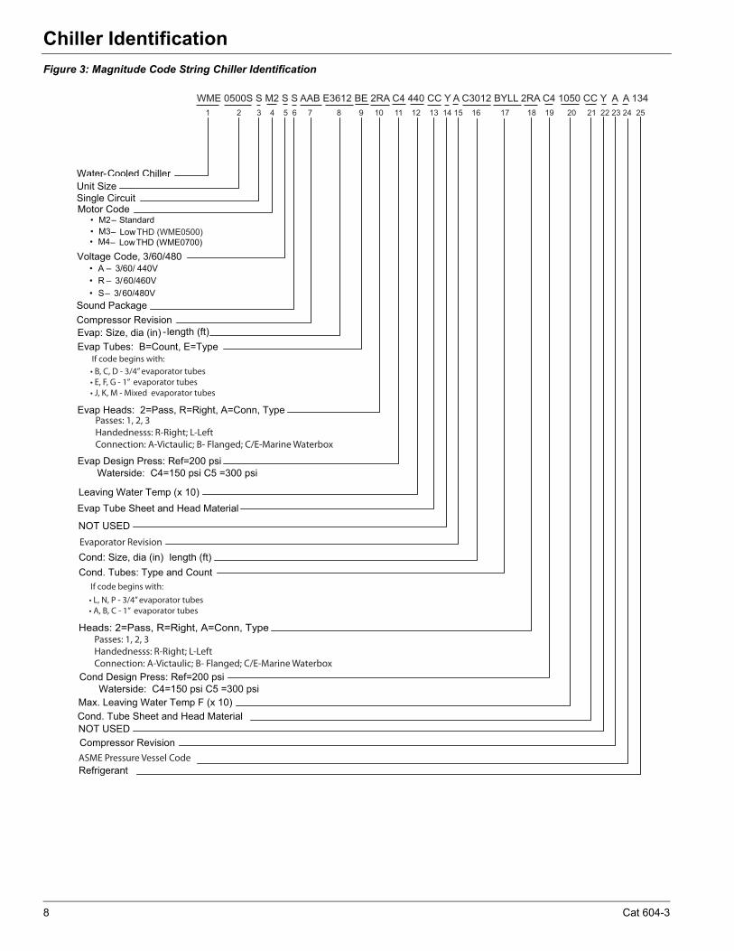
Chiller IdentificationFigure 3: Magnitude Code String Chiller Identification
Water-Cooled Chiller Unit Size Single Circuit Motor Code
� M2 – Standard � M3 – Low THD (WME0500)
Voltage Code, 3/60/480 � A – 3/60/ 440V
� R – 3/60/460V � S – 3/60/480V
Sound Package
Evap: Size, dia (in) -length (ft) Evap Tubes: B=Count, E=Type
Evap Heads: 2=Pass, R=Right, A=Conn, Type
Evap Design Press: Ref=200 psi Waterside: C4=150 psi C5 =300 psi
Leaving Water Temp (x 10)
NOT USED
Cond: Size, dia (in) length (ft)Cond. Tubes: Type and Count
Heads: 2=Pass, R=Right, A=Conn, Type
Evap Tube Sheet and Head Material
Refrigerant
Compressor Revision
WME 0500S S M2 S S AAB E3612 BE 2RA C4 440 CC Y A C3012 BYLL 2RA C4 1050 CC Y A A 134 1 2 3 4 5 6 7 8 9 10 11 12 13 14 15 16 17 18 19 20 21 22 23 24 25
Passes: 1, 2, 3Handednesss: R-Right; L-LeftConnection: A-Victaulic; B- Flanged; C/E-Marine Waterbox
Evaporator Revision
Passes: 1, 2, 3Handednesss: R-Right; L-LeftConnection: A-Victaulic; B- Flanged; C/E-Marine Waterbox
Cond Design Press: Ref=200 psi Waterside: C4=150 psi C5 =300 psiMax. Leaving Water Temp F (x 10)Cond. Tube Sheet and Head MaterialNOT USEDCompressor Revision ASME Pressure Vessel Code
� M4 – Low THD (WME0700)
If code begins with:
If code begins with:
8 Cat 604-3
Chiller Identification
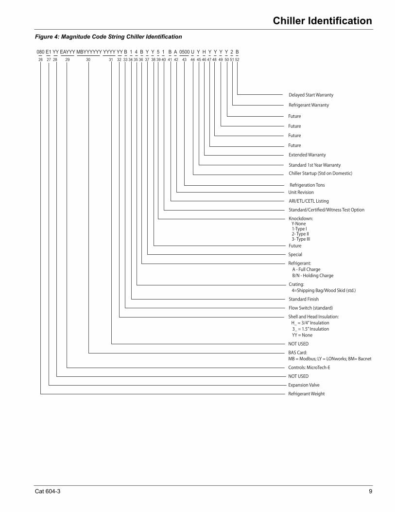
Figure 4: Magnitude Code String Chiller Identification
080 E1 YY EAYYY MBYYYYYY YYYY YY B 1 4 B Y Y 5 1 B A 0500 U Y H Y Y Y Y 2 B 26 27 28 29 30 31 32 33 34 35 36 37 38 39 40 41 42 43 44 45 46 47 48 49 50 51 52
Refrigerant Weight
Expansion Valve
NOT USED
Controls: MicroTech-E
BAS Card: MB = Modbus; LY = LONworks; BM= Bacnet
NOT USED
Shell and Head Insulation: H_ = 3/4” Insulation 3_ = 1.5” Insulation YY = None
Flow Switch (standard)
Standard Finish
Crating: 4=Shipping Bag/Wood Skid (std.)
Refrigerant: A - Full Charge B/N - Holding Charge
Special
Future
Knockdown: Y-None 1-Type I 2- Type II 3- Type III
Standard/Certified/Witness Test Option
ARI/ETL/CETL Listing
Unit Revision
Chiller Startup (Std on Domestic)
Extended Warranty
Refrigeration Tons
Standard 1st Year Warranty
Future
Future
Future
Future
Refrigerant Warranty
Delayed Start Warranty
Cat 604-3 9
Electrical Data
Electrical DataElectrical Notes1 Units are available for 460 or 440 to 480 VAC at 60 Hz.
2 Wiring, fuse and wire size must be in accordance with the National Electric Code (NEC).
3 Important: Voltage unbalance not to exceed 2%.
Power Wiring
Use only copper supply wires with ampacity based on 75°C conductor rating. Connections to terminals must be made with copper lugs and copper wire.
Lug size range is: (3) 3/0 AWG - 500 kc mil.
Power Factor Correction Capacitors
Do not use power factor correction capacitors with(WME chillers. Doing so can cause harmful electrical resonance in the system. Correction capacitors are not necessary since VFDs inherently maintain high power factors
Short Circuit Current Ratings
The standard short circuit rating is 35kA for 460 V. Optional high short circuit current ratings are available for 65kA, and 100kA with a matching circuit breaker.
The optional circuit breaker must be sized to meet these ratings.
3-Phase vs. 6-phase Motors
WME 500 motors are designated as M2 or M3.
• "M2 motors are standard 3-phase and the VFD performs similar to a 6-pulse drive.
• "M3 motors are 6-phase (connected to a 3-phase power supply) and the VFD performs similar to a 12-pulse drive. They provide increased protection against harmonic distortion, but are not required on most applications.
WME 700 motors are 6-phase and designated as M4. The VFD performs similar to a 12-pulse drive.
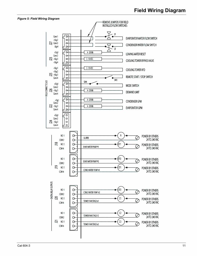
Notes for field wiring diagram
1 All line-side wiring must be in accordance with the NEC and be made with copper wire and copper lugs only.
2 A customer furnished 24 to 240 Vac power for alarm relay coil may be connected at J18. Maximum rating of the alarm relay coil is 25 VA.
3 Remote on/off control of unit can be accomplished by connecting a set of isolated dry contacts at J25.
4 If field supplied pressure differential flow switches are used, they must be installed across the vessel and not the pump. They must provide isolated dry contacts at J27.
5 An optional customer supplied 25 VA maximum coil rated, chilled water pump relay (one or two) may be wired as shown. This option will cycle the chilled water pump in response to chiller demand.
6 The condenser water pump must cycle with the unit. A customer supplied 25 VA maximum coil rated, condenser water pump relay (one or two) must be wired as shown. Units used in a free-cooling application must have condenser water above 50°F before starting.
7 Optional customer supplied 25 VA maximum coil rated cooling tower fan relays may be wired as shown. This option will cycle the cooling tower fans as prescribed by the tower control set points.
8 External 4-20mA signals can be wired to J23 for leaving (chilled) water reset and to J26 for demand limit.
10 Cat 604-3
Field Wiring Diagram
Field Wiring DiagramFigure 5: Field Wiring Diagram
Cat 604-3 11
Dimension Drawings
Dimension DrawingsDrawing Notes1 All dimensions are in inches [millimeters] unless noted
otherwise.
2 Final connections must allow for 0.5 inch +/- (12.7mm) manufacturing tolerances.
3 1.00-inch FPT [25.4 mm] evaporator and condenser relief valves must be piped per ANSI / ASHRAE 15. Number of relief valves is 1 per evaporator and 2 per condenser.
4 .375 inch [9 mm] suction nozzle relief valve must be piped per ANSI / ASHRAE 15.
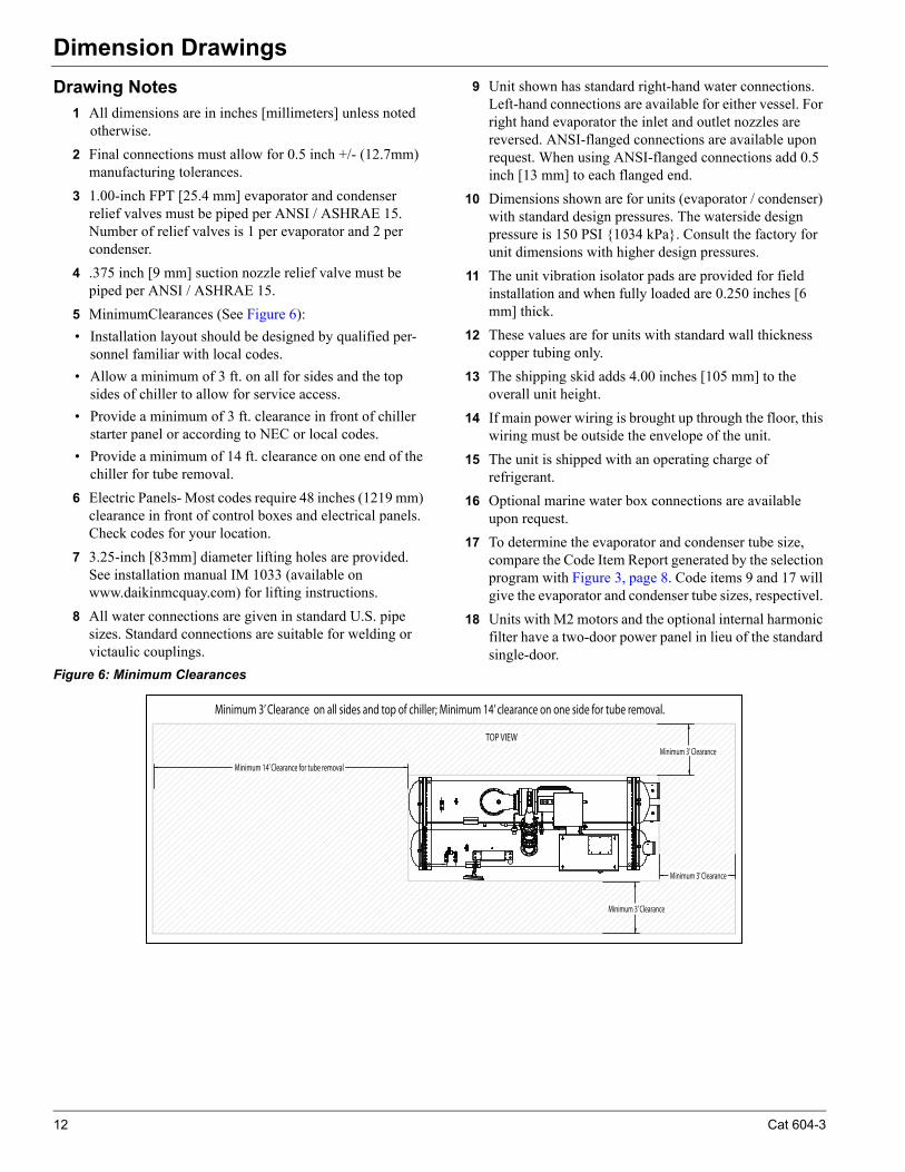
5 MinimumClearances (See Figure 6):
• Installation layout should be designed by qualified per-sonnel familiar with local codes.
• Allow a minimum of 3 ft. on all for sides and the top sides of chiller to allow for service access.
• Provide a minimum of 3 ft. clearance in front of chiller starter panel or according to NEC or local codes.
• Provide a minimum of 14 ft. clearance on one end of the chiller for tube removal.
6 Electric Panels- Most codes require 48 inches (1219 mm) clearance in front of control boxes and electrical panels. Check codes for your location.
7 3.25-inch [83mm] diameter lifting holes are provided. See installation manual IM 1033 (available on www.daikinmcquay.com) for lifting instructions.
8 All water connections are given in standard U.S. pipe sizes. Standard connections are suitable for welding or victaulic couplings.
9 Unit shown has standard right-hand water connections. Left-hand connections are available for either vessel. For right hand evaporator the inlet and outlet nozzles are reversed. ANSI-flanged connections are available upon request. When using ANSI-flanged connections add 0.5 inch [13 mm] to each flanged end.
10 Dimensions shown are for units (evaporator / condenser) with standard design pressures. The waterside design pressure is 150 PSI {1034 kPa}. Consult the factory for unit dimensions with higher design pressures.
11 The unit vibration isolator pads are provided for field installation and when fully loaded are 0.250 inches [6 mm] thick.
12 These values are for units with standard wall thickness copper tubing only.
13 The shipping skid adds 4.00 inches [105 mm] to the overall unit height.
14 If main power wiring is brought up through the floor, this wiring must be outside the envelope of the unit.
15 The unit is shipped with an operating charge of refrigerant.
16 Optional marine water box connections are available upon request.
17 To determine the evaporator and condenser tube size, compare the Code Item Report generated by the selection program with Figure 3, page 8. Code items 9 and 17 will give the evaporator and condenser tube sizes, respectivel.
18 Units with M2 motors and the optional internal harmonic filter have a two-door power panel in lieu of the standard single-door.
Figure 6: Minimum Clearances
Minimum 14’ Clearance for tube removal
TOP VIEWMinimum 3’ Clearance
Minimum 3’ Clearance on all sides and top of chiller; Minimum 14’ clearance on one side for tube removal.
Minimum 3’ Clearance
Minimum 3’ Clearance
12 Cat 604-3
Dimension Drawings
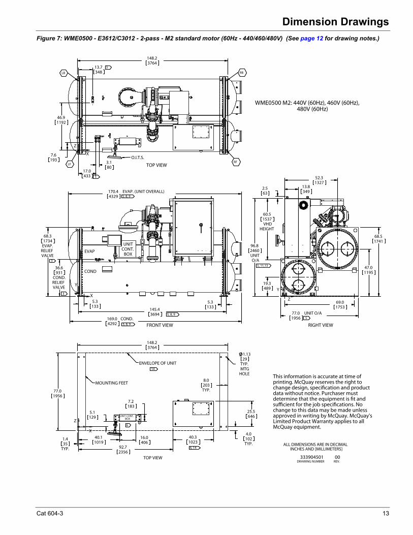
Figure 7: WME0500 - E3612/C3012 - 2-pass - M2 standard motor (60Hz - 440/460/480V) (See page 12 for drawing notes.)
5.3133
145.43694
5.3133
170.4 EVAP. (UNIT OVERALL)4329
169.0 COND.4292
36.6
COND.RELIEFVALVE
931
68.3
EVAP.RELIEFVALVE
1734
3
3
5, 8, 9
5, 8, 9
5, 8, 9
FRONT VIEW
X
Y
COND
EVAP
UNITCONT.
BOX
6
60.5
VHDHEIGHT
1537
19.3489
47.01195
69.01753
77.0 UNIT O/A1956
96.8
UNITO/A
2460
13.8349
52.31327
68.51741
2.563
5
5, 11,13
RIGHT VIEW
Z
Y
17.0433
3.180
7.6193
46.91192
13.7348
148.23764
3
3
TOP VIEW
O.I.T.S.
X
Z
LB
LF RF
RB
148.23764
16.0406
7.2183
40.31023
1.4
TYP.35
40.11019
92.72356
4.0
TYP.102
25.5646
8.0
TYP.203
1.13
TYP.MTG
HOLE
29
77.01956
5.1129 UNIT CONT.
BOX
6, 14
ENVELOPE OF UNIT
14
MOUNTING FEET
X
Z
TOP VIEW
ALL DIMENSIONS ARE IN DECIMALINCHES AND [MILLIMETERS]
333904501DRAWING NUMBER
00REV.
This information is accurate at time of printing. McQuay reserves the right to change design, specification and product data without notice. Purchaser must determine that the equipment is fit and sufficient for the job specifications. No change to this data may be made unless approved in writing by McQuay. McQuay's Limited Product Warranty applies to all McQuay equipment.
WME0500 M2: 440V (60Hz), 460V (60Hz), 480V (60Hz)
Cat 604-3 13
Dimension Drawings
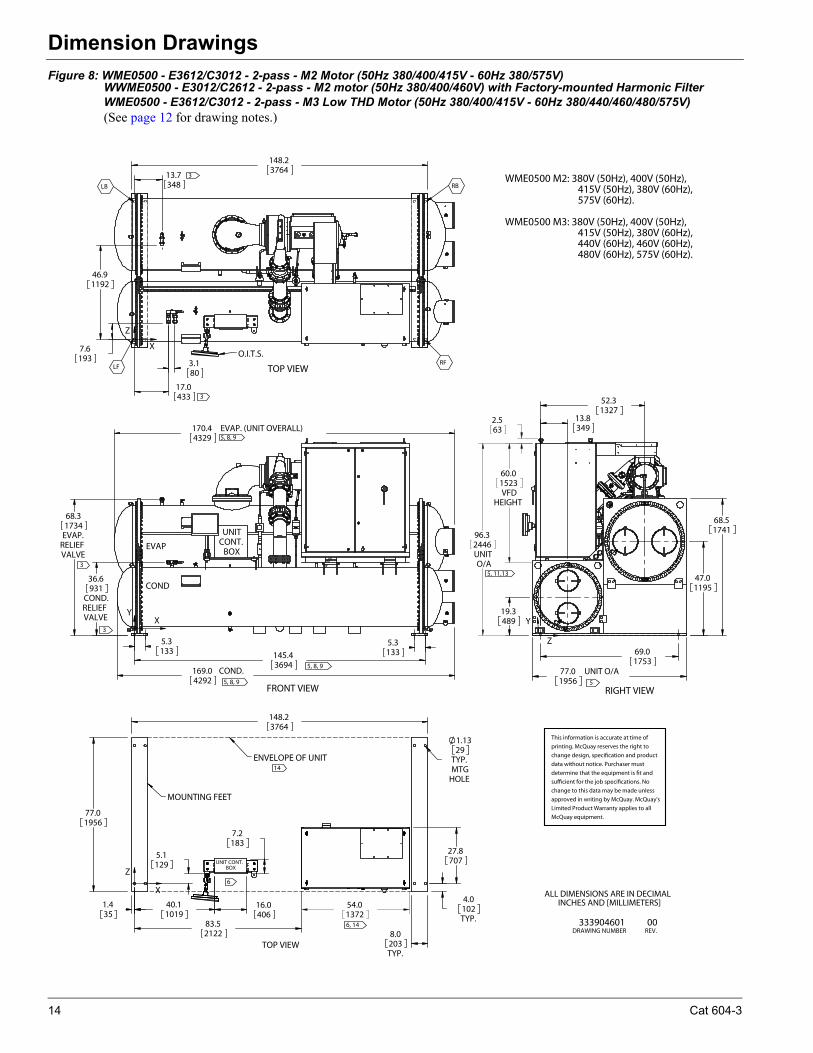
Figure 8: WME0500 - E3612/C3012 - 2-pass - M2 Motor (50Hz 380/400/415V - 60Hz 380/575V) WWME0500 - E3012/C2612 - 2-pass - M2 motor (50Hz 380/400/460V) with Factory-mounted Harmonic FilterWME0500 - E3612/C3012 - 2-pass - M3 Low THD Motor (50Hz 380/400/415V - 60Hz 380/440/460/480/575V) (See page 12 for drawing notes.)
5.3133
145.43694
5.3133
170.4 EVAP. (UNIT OVERALL)4329
169.0 COND.4292
36.6
COND.RELIEFVALVE
931
68.3
EVAP.RELIEFVALVE
1734
3
3
5, 8, 9
5, 8, 9
5, 8, 9
FRONT VIEW
XY
COND
EVAP
UNITCONT.
BOX
19.3489
47.01195
69.01753
77.0 UNIT O/A1956
13.8349
52.31327
68.51741
2.563
60.0
VFDHEIGHT
1523
96.3
UNITO/A
2446
5
5, 11,13
RIGHT VIEW
Z
Y
17.0433
3.180
7.6193
46.91192
13.7348
148.23764
3
3
TOP VIEW
O.I.T.S.
X
Z
LB
LF RF
RB
148.23764
16.0406
7.2183
1.435
40.11019
83.52122
4.0
TYP.102
27.8707
8.0
TYP.203
1.13
TYP.MTG
HOLE
29
77.01956
5.1129
54.01372
UNIT CONT.BOX
6, 14
ENVELOPE OF UNIT 14
MOUNTING FEET
X
Z
TOP VIEW
6
333904601DRAWING NUMBER
00REV.
ALL DIMENSIONS ARE IN DECIMALINCHES AND [MILLIMETERS]
WME0500 M2: 380V (50Hz), 400V (50Hz), 415V (50Hz), 380V (60Hz), 575V (60Hz).
WME0500 M3: 380V (50Hz), 400V (50Hz), 415V (50Hz), 380V (60Hz), 440V (60Hz), 460V (60Hz), 480V (60Hz), 575V (60Hz).
This information is accurate at time of
printing. McQuay reserves the right to
change design, specification and product
data without notice. Purchaser must
determine that the equipment is fit and
sufficient for the job specifications. No
change to this data may be made unless
approved in writing by McQuay. McQuay's
Limited Product Warranty applies to all
McQuay equipment.
14 Cat 604-3
Dimension Drawings
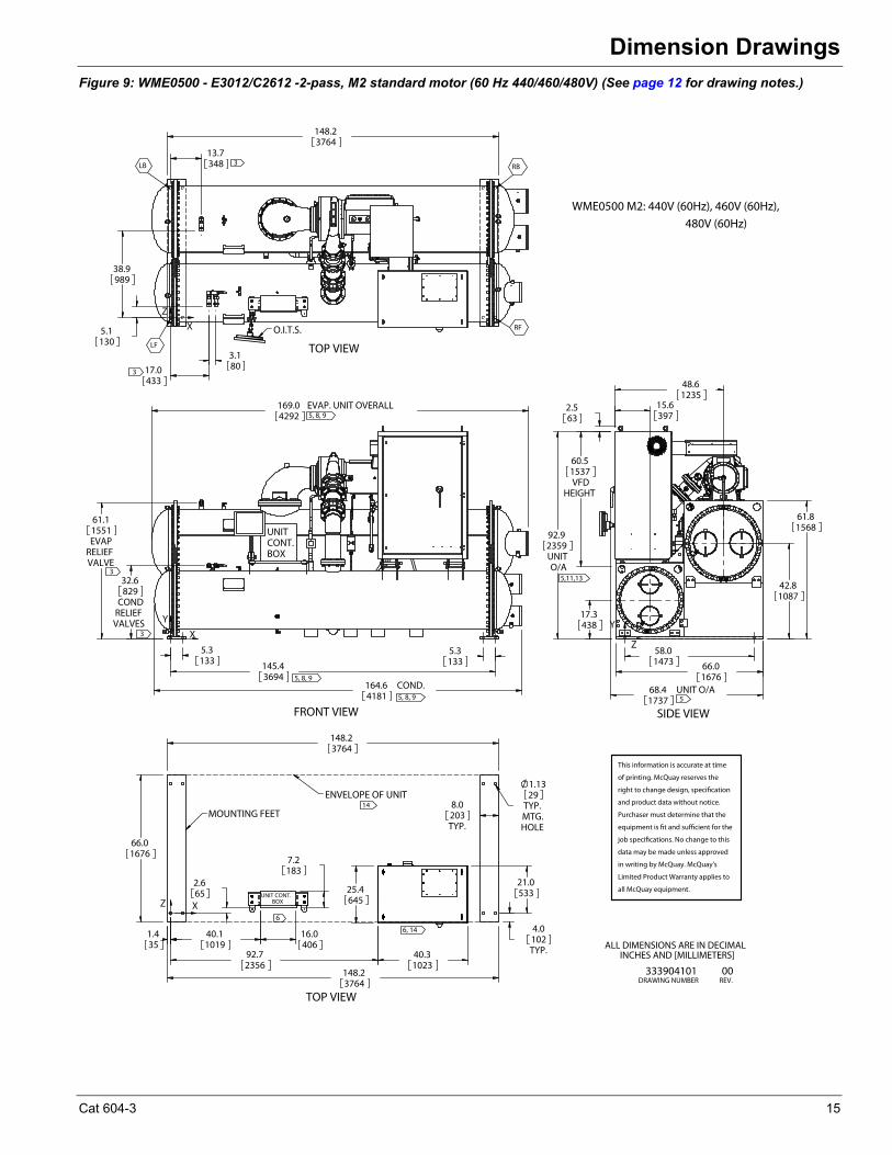
Figure 9: WME0500 - E3012/C2612 -2-pass, M2 standard motor (60 Hz 440/460/480V) (See page 12 for drawing notes.)
32.6
CONDRELIEFVALVES
829
61.1
EVAPRELIEFVALVE
1551
5.3133
164.6 COND.4181
145.43694
5.3133
169.0 EVAP. UNIT OVERALL4292
5, 8, 9
5, 8, 9
3
3
5, 8, 9
Y
X
FRONT VIEW
UNITCONT.BOX
58.01473
68.4 UNIT O/A1737
42.81087
92.9
UNITO/A
2359
48.61235
15.6397
61.81568
66.01676
17.3438
60.5
VFDHEIGHT
1537
2.563
5,11,13
5
Z
Y
SIDE VIEW
148.23764
13.7348
38.9989
5.1130
17.0433
3.180
3
3
X
Z
TOP VIEW
O.I.T.S.
LB
LF
RF
RB
66.01676
1.435
40.11019
16.0406
7.2183
4.0
TYP.102
8.0
TYP.203
148.23764
1.13
TYP.MTG.HOLE
29
21.0533
92.72356
40.31023
25.4645
2.665
148.23764
XZ
TOP VIEW
UNIT CONT.BOX
ENVELOPE OF UNIT
MOUNTING FEET
6
6, 14
14
ALL DIMENSIONS ARE IN DECIMALINCHES AND [MILLIMETERS]
333904101DRAWING NUMBER
00REV.
WME0500 M2: 440V (60Hz), 460V (60Hz),
480V (60Hz)
This information is accurate at time
of printing. McQuay reserves the
right to change design, specification
and product data without notice.
Purchaser must determine that the
equipment is fit and sufficient for the
job specifications. No change to this
data may be made unless approved
in writing by McQuay. McQuay's
Limited Product Warranty applies to
all McQuay equipment.
Cat 604-3 15
Dimension Drawings
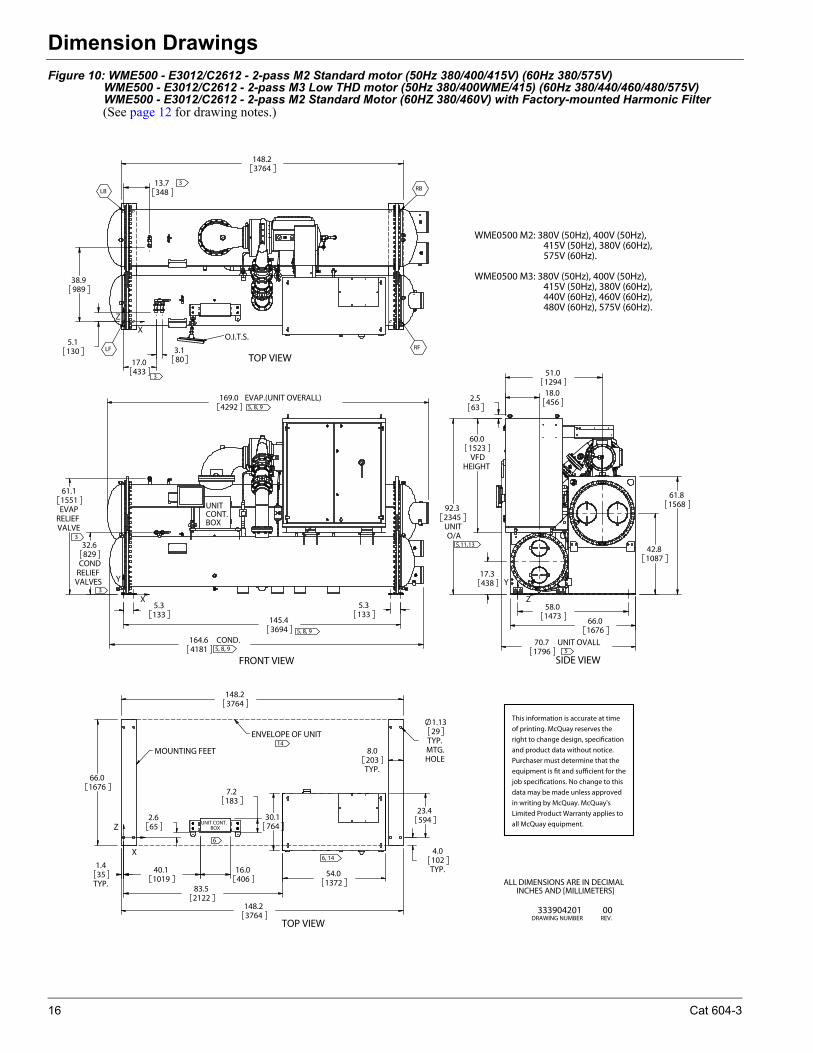
Figure 10: WME500 - E3012/C2612 - 2-pass M2 Standard motor (50Hz 380/400/415V) (60Hz 380/575V) WME500 - E3012/C2612 - 2-pass M3 Low THD motor (50Hz 380/400WME/415) (60Hz 380/440/460/480/575V) WME500 - E3012/C2612 - 2-pass M2 Standard Motor (60HZ 380/460V) with Factory-mounted Harmonic Filter(See page 12 for drawing notes.)
32.6
CONDRELIEFVALVES
829
61.1
EVAPRELIEFVALVE
1551
5.3133
164.6 COND.4181
145.43694
5.3133
169.0 EVAP.(UNIT OVERALL)4292
5, 8, 9
5, 8, 9
3
3
5, 8, 9
FRONT VIEW
Y
X
UNITCONT.BOX
58.01473
70.7 UNIT OVALL1796
42.81087
61.81568
66.01676
17.3438
60.0
VFDHEIGHT
1523
51.01294
18.0456
92.3
UNITO/A
2345
2.563
5,11,13
5
SIDE VIEW
Y
Z
148.23764
13.7348
38.9989
5.1130
17.0433
3.180
3
3
TOP VIEW
LB
LF RF
RB
O.I.T.S.
X
Z
66.01676
1.4
TYP.35
40.11019
16.0406
7.2183
30.1764
83.52122
54.01372
4.0
TYP.102
23.4594
8.0
TYP.203
148.23764
2.665
148.23764
1.13
TYP.MTG.HOLE
29
TOP VIEW
ENVELOPE OF UNIT
MOUNTING FEET
UNIT CONT.BOX
X
Z
14
6, 14
6
ALL DIMENSIONS ARE IN DECIMALINCHES AND [MILLIMETERS]
333904201DRAWING NUMBER
00REV.
This information is accurate at time
of printing. McQuay reserves the
right to change design, specification
and product data without notice.
Purchaser must determine that the
equipment is fit and sufficient for the
job specifications. No change to this
data may be made unless approved
in writing by McQuay. McQuay's
Limited Product Warranty applies to
all McQuay equipment.
WME0500 M2: 380V (50Hz), 400V (50Hz), 415V (50Hz), 380V (60Hz), 575V (60Hz).
WME0500 M3: 380V (50Hz), 400V (50Hz), 415V (50Hz), 380V (60Hz), 440V (60Hz), 460V (60Hz), 480V (60Hz), 575V (60Hz).
16 Cat 604-3
Dimension Drawings
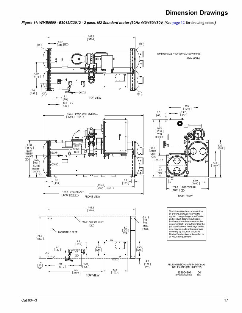
Figure 11: WME0500 - E3012/C3012 - 2 pass, M2 Standard motor (60Hz 440/460/480V, (See page 12 for drawing notes.)
5.3133
145.43694
169.0 CONDENSER4292
36.6
CONDRELIEFVALVE
931
61.8
EVAPRELIEFVALVE
1570
5.3133
169.0 EVAP. UNIT OVERALL4292
3
3
5, 8, 9
5, 8, 9
5, 8, 9
FRONT VIEW
X
Y
COND
EVAP
UNITCONT.
BOX
63.01600
71.0 UNIT OVERALL1803
49.21249
13.7347
43.61107
62.51589
19.3489
96.8
UNITO/A
2460
60.5
VFDHEIGHT
1537
2.563
5
5,11,13
RIGHT VIEW
Z
Y
7.6193
43.91116
17.0433
3.180
13.7348
148.23764
3
3
RB
RF LF
LR
TOP VIEW
O.I.T.S.
X
Z
71.01803
148.23764
8.0
TYP.203
1.4
TYP.35
40.11019
16.0406
7.2183
5.1
129
4.0
TYP.102
92.72356
40.31023
25.5646
1.13
TYP.MTG.HOLE
29
25.4645UNIT CONT.
BOX
6, 14
ENVELOPE OF UNIT 14
MOUNTING FEET
X
Z
TOP VIEW
6
ALL DIMENSIONS ARE IN DECIMALINCHES AND [MILLIMETERS]
333904301DRAWING NUMBER
00REV.
This information is accurate at time of printing. McQuay reserves the right to change design, specification and product data without notice. Purchaser must determine that the equipment is fit and sufficient for the job specifications. No change to this data may be made unless approved in writing by McQuay. McQuay's Limited Product Warranty applies to all McQuay equipment.
WME0500 M2: 440V (60Hz), 460V (60Hz),
480V (60Hz)
Cat 604-3 17
Dimension Drawings
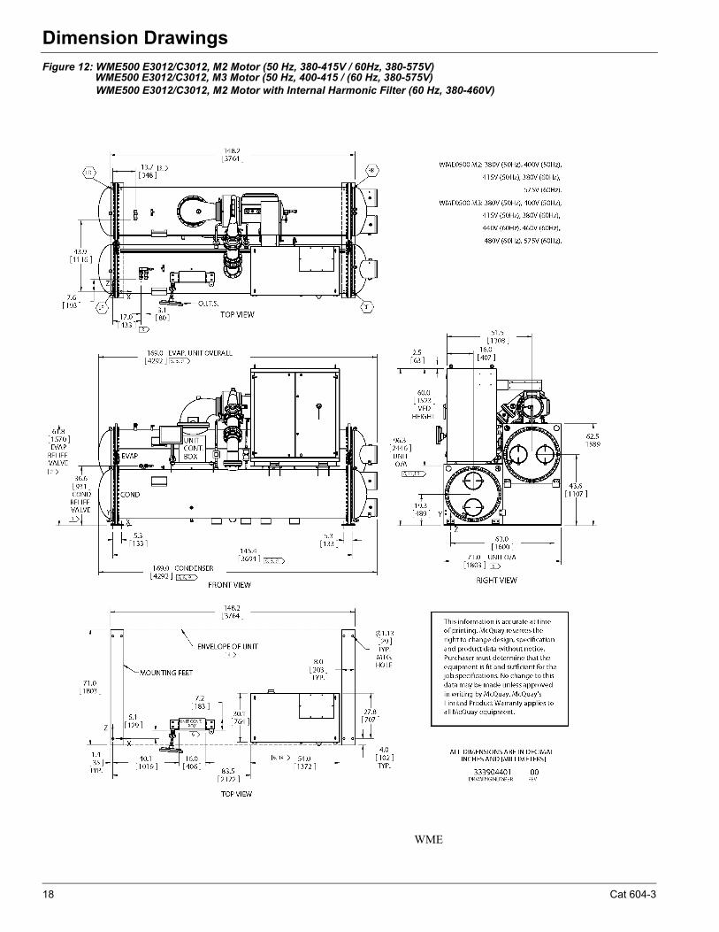
Figure 12: WME500 E3012/C3012, M2 Motor (50 Hz, 380-415V / 60Hz, 380-575V)WME500 E3012/C3012, M3 Motor (50 Hz, 400-415 / (60 Hz, 380-575V)WME500 E3012/C3012, M2 Motor with Internal Harmonic Filter (60 Hz, 380-460V)
WME
18 Cat 604-3
Dimension Drawings
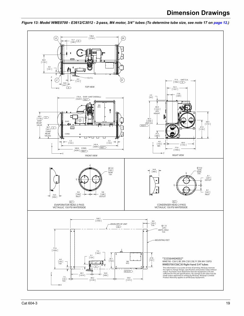
Figure 13: Model WME0700 - E3612/C3012 - 2-pass, M4 motor, 3/4” tubes (To determine tube size, see note 17 on page 12.)
170.4 EVAP. (UNIT OVERALL)4329
68.3
EVAPRELIEFVALVE
1736
36.7
CONDRELIEFVALVES
931
169.0 COND.4292
5.3133
145.43694
5.3133
FRONT VIEW
UNITCONTR.
BOX
COND.
EVAP.
M4VFD
3
4,6,7
4,6,7
X
Y
4,6,7
3
69.01753
77.01956
19.3489
96.3
UNIT O.A.2446
60.0
VFDHEIGHT
1523
13.83492.5
63
52.31327
47.01195
68.51741
77.3 UNIT O.A.1962
4.0
REF.102
RIGHT VIEW
4
Y
Z
4,9,11
148.23764
16.8427
6.2157
46.91192
4.0101
13.7348
TOP VIEW
Z
LFO.I.T.S.
RF
RBLB
3
3X
WME700 - E3612 BE 2RA C3012 BLYY 2RA M4 150PSI*333564404002*
8.1
OUTLET207
8.1
INLET207
10.0[254]NOM.TYP.CL
CL
16.0406
77.01956
148.23764 8.0
TYP.203
1.13
MNTG. HOLETYP.
29
27.8707
1.4
TYP.35
5.1129
7.2183
30.1764
84.22139
54.01372
40.11019
16.0406
4.0
TYP.102
MOUNTING FEET
ENVELOPE OF UNIT
12
X
Z
4
4,12,13
UNIT CONTR.BOX
M4VFD
9.8
INLET248
9.8
OUTLET248
12.0
NOM.TYP.
305
CL
CL
16.0406
6,7
CONDENSER HEAD 2-PASSVICTAULIC 150 PSI WATERSIDE
6,7
EVAPORATOR HEAD 2-PASS VICTAULIC 150 PSI WATERSIDE
This information is accurate at time of printing. McQuay reservesthe right to change design, specification and product data withoutnotice. Purchaser must determine that the equipment is fit andsufficient for the job specifications. No change to this data may bemade unless approved in writing by McQuay. McQuay's LimitedProduct Warranty applies to all McQuay equipment.
WME0700 E36C30 Right-hand 3/4” tubes
Cat 604-3 19
Dimension Drawings
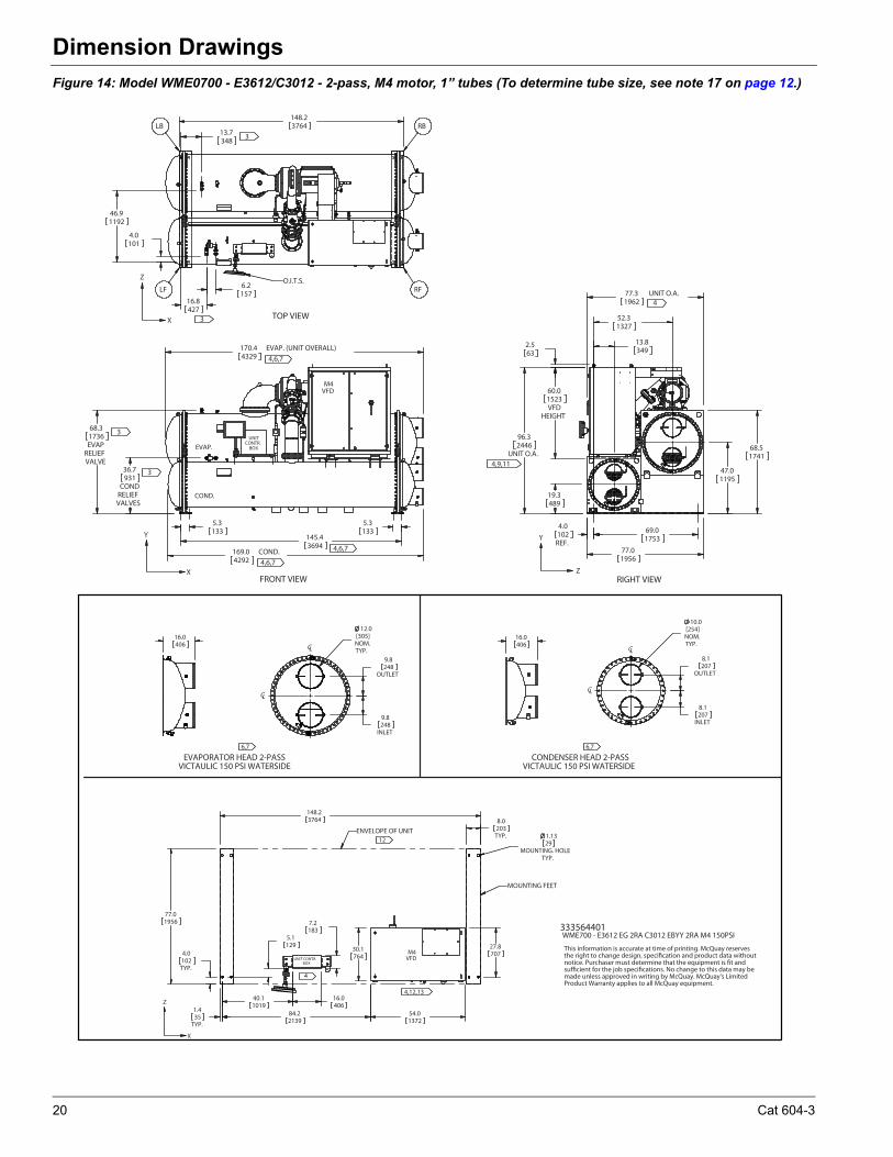
Figure 14: Model WME0700 - E3612/C3012 - 2-pass, M4 motor, 1” tubes (To determine tube size, see note 17 on page 12.)
170.4 EVAP. (UNIT OVERALL)4329
68.3
EVAPRELIEFVALVE
1736
36.7
CONDRELIEFVALVES
931
169.0 COND.4292
5.3133
145.43694
5.3133
FRONT VIEW
4,6,7
UNITCONTR.
BOX
COND.
EVAP.
M4VFD
3
3
4,6,7
4,6,7
X
Y69.01753
77.01956
19.3489
96.3
UNIT O.A.2446
60.0
VFDHEIGHT
1523
47.01195
52.31327
13.8349
2.563
4.0
REF.102
77.3 UNIT O.A.1962
68.51741
RIGHT VIEW
4
Y
Z
4,9,11
148.23764
16.8427
6.2157
46.91192
4.0101
13.7348
TOP VIEW
Z
LFO.I.T.S.
RF
RBLB
3
3X
333564401WME700 - E3612 EG 2RA C3012 EBYY 2RA M4 150PSI
8.1
OUTLET207
8.1
INLET207
TYP.
10.0[254]NOM.
CL
CL
16.0406
77.01956
148.23764 8.0
TYP.203
1.13
MOUNTING. HOLETYP.
29
27.8707
1.4
TYP.35
5.1129
7.2183
30.1764
84.22139
54.01372
40.11019
16.0406
4.0
TYP.102
ENVELOPE OF UNIT
12
X
Z
4
4,12,13
UNIT CONTR.BOX
M4VFD
TYP.
12.0[305]NOM.
9.8
OUTLET248
9.8
INLET248
CL
CL
16.0406
6,7
CONDENSER HEAD 2-PASSVICTAULIC 150 PSI WATERSIDE
6,7
EVAPORATOR HEAD 2-PASS VICTAULIC 150 PSI WATERSIDE
This information is accurate at time of printing. McQuay reservesthe right to change design, specification and product data withoutnotice. Purchaser must determine that the equipment is fit andsufficient for the job specifications. No change to this data may bemade unless approved in writing by McQuay. McQuay's LimitedProduct Warranty applies to all McQuay equipment.
MOUNTING FEET
20 Cat 604-3
Dimension Drawings
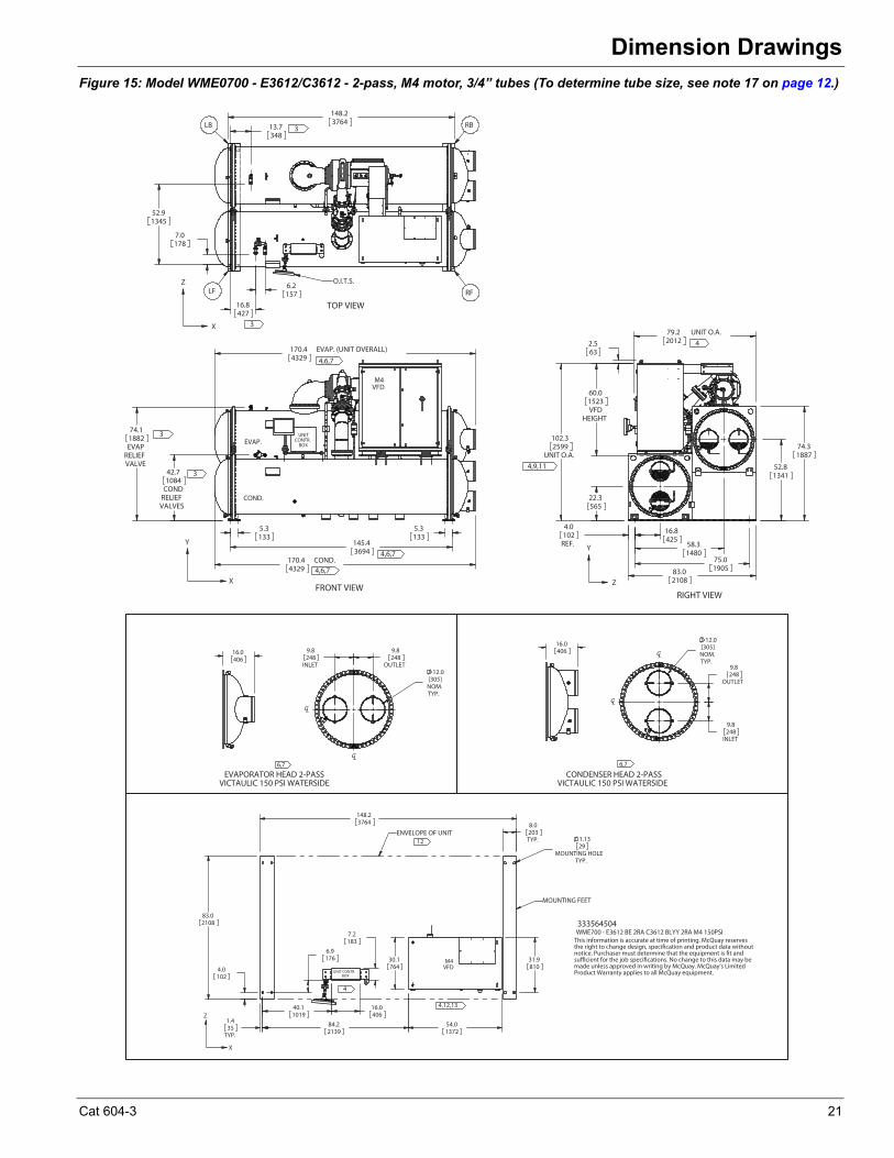
Figure 15: Model WME0700 - E3612/C3612 - 2-pass, M4 motor, 3/4” tubes (To determine tube size, see note 17 on page 12.)
74.1
EVAPRELIEFVALVE
1882
42.7
CONDRELIEFVALVES
1084
170.4 COND.4329
5.3133
5.3133
145.43694
170.4 EVAP. (UNIT OVERALL)4329
FRONT VIEW
UNITCONTR.
BOX
COND.
EVAP.
M4VFD
3
4,6,7
4,6,7
4,6,7
3
22.3565
102.3
UNIT O.A.2599
60.0
VFDHEIGHT
1523
74.31887
16.8425
2.563
79.2 UNIT O.A.2012
4.0
REF.102
75.0190583.0
2108
52.81341
58.31480
RIGHT VIEW
4
4,9,11
6.2157
13.7348
148.23764
16.8427
7.0178
52.91345
TOP VIEW
LF
O.I.T.S.
RF
RBLB3
3
Z
X
X
YY
Z
333564504WME700 - E3612 BE 2RA C3612 BLYY 2RA M4 150PSI
148.23764
6.9176
7.2183
30.1764
84.22139
54.01372
40.11019
16.0406
1.13
MOUNTING HOLETYP.
29
31.9810
8.0
TYP.203
1.4
TYP.35
83.02108
4.0102
ENVELOPE OF UNIT
12
4
4,12,13
UNIT CONTR.BOX
M4VFD
TYP.
12.0[305]NOM.
9.8
OUTLET248
9.8
INLET248
CL
CL
16.0406
TYP.
12.0[305]NOM.
9.8
INLET248
9.8
OUTLET248
CL
CL
16.0406
6,7
CONDENSER HEAD 2-PASSVICTAULIC 150 PSI WATERSIDE
6,7
EVAPORATOR HEAD 2-PASS VICTAULIC 150 PSI WATERSIDE
This information is accurate at time of printing. McQuay reservesthe right to change design, specification and product data withoutnotice. Purchaser must determine that the equipment is fit andsufficient for the job specifications. No change to this data may bemade unless approved in writing by McQuay. McQuay's LimitedProduct Warranty applies to all McQuay equipment.
MOUNTING FEET
Z
X
Cat 604-3 21
Dimension Drawings
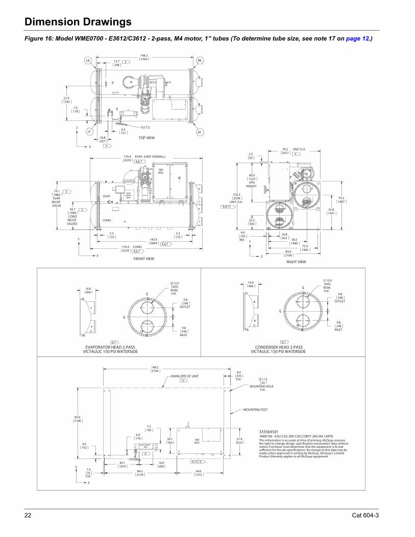
Figure 16: Model WME0700 - E3612/C3612 - 2-pass, M4 motor, 1” tubes (To determine tube size, see note 17 on page 12.)
170.4 EVAP. (UNIT OVERALL)4329
74.1
EVAPRELIEFVALVE
1882
42.7
CONDRELIEFVALVES
1084
170.4 COND.4329
5.3133
5.3133
145.43694
FRONT VIEW
4,6,7
UNITCONTR.
BOX
COND.
EVAP.
M4VFD
3
3
4,6,7
4,6,7
22.3565
102.3
UNIT O.A.2599
60.0
VFDHEIGHT
1523
52.81341
74.31887
58.31480
16.8425
2.563
79.2 UNIT O.A.2012
4.0
REF.102
75.01905
83.02108
RIGHT VIEW
4
4,9,11
6.2157
13.7348
148.23764
16.8427
7.0178
52.91345
TOP VIEW
LF
O.I.T.S.
RF
RBLB3
3
Z
X
X
YY
Z
333564501WME700 - E3612 EG 2RA C3612 EBYY 2RA M4 150PSI
148.23764
6.9176
7.2183
30.1764
84.22139
54.01372
40.11019
16.0406
1.13
MOUNTING HOLETYP.
29
31.9810
8.0
TYP.203
1.4
TYP.35
83.02108
4.0102
ENVELOPE OF UNIT
12
4
4,12,13
UNIT CONTR.BOX
M4VFD
9.8
OUTLET248
9.8
INLET248
TYP.
12.0[305]NOM.
CL
CL
16.0406 TYP.
12.0[305]NOM.
9.8
OUTLET248
9.8
INLET248
CL
CL
16.0406
6,7
CONDENSER HEAD 2-PASSVICTAULIC 150 PSI WATERSIDE
6,7
EVAPORATOR HEAD 2-PASS VICTAULIC 150 PSI WATERSIDE
This information is accurate at time of printing. McQuay reservesthe right to change design, specification and product data withoutnotice. Purchaser must determine that the equipment is fit andsufficient for the job specifications. No change to this data may bemade unless approved in writing by McQuay. McQuay's LimitedProduct Warranty applies to all McQuay equipment.
MOUNTING FEET
Z
X
22 Cat 604-3
Dimension Drawings
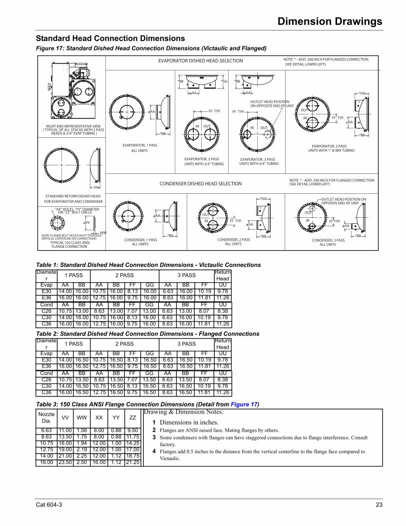
Standard Head Connection DimensionsFigure 17: Standard Dished Head Connection Dimensions (Victaulic and Flanged)
Table 2: Standard Dished Head Connection Dimensions - Flanged Connections
Table 3: 150 Class ANSI Flange Connection Dimensions (Detail from Figure 17)
Table 1: Standard Dished Head Connection Dimensions - Victaulic Connections Diamete
r1 PASS 2 PASS 3 PASS
Return Head
Evap AA BB AA BB FF GG AA BB FF UUE30 14.00 16.00 10.75 16.00 8.13 16.00 6.63 16.00 10.19 9.78E36 16.00 16.00 12.75 16.00 9.75 16.00 8.63 16.00 11.81 11.26
Cond AA BB AA BB FF GG AA BB FF UUC26 10.75 13.00 8.63 13.00 7.07 13.00 6.63 13.00 8.07 8.38C30 14.00 16.00 10.75 16.00 8.13 16.00 6.63 16.00 10.19 9.78C36 16.00 16.00 12.75 16.00 9.75 16.00 8.63 16.00 11.81 11.26
Diameter
1 PASS 2 PASS 3 PASSReturn Head
Evap AA BB AA BB FF GG AA BB FF UUE30 14.00 16.50 10.75 16.50 8.13 16.50 6.63 16.50 10.19 9.78E36 16.00 16.50 12.75 16.50 9.75 16.50 8.63 16.50 11.81 11.26
Cond AA BB AA BB FF GG AA BB FF UUC26 10.75 13.50 8.63 13.50 7.07 13.50 6.63 13.50 8.07 8.38C30 14.00 16.50 10.75 16.50 8.13 16.50 6.63 16.50 10.19 9.78C36 16.00 16.50 12.75 16.50 9.75 16.50 8.63 16.50 11.81 11.26
NozzleDia.
VV WW XX YY ZZDrawing & Dimension Notes:
1 Dimensions in inches.2 Flanges are ANSI raised face. Mating flanges by others.3 Some condensers with flanges can have staggered connections due to flange interference. Consult
factory.4 Flanges add 0.5 inches to the distance from the vertical centerline to the flange face compared to
Victaulic.
6.63 11.00 1.56 8.00 0.88 9.508.63 13.50 1.75 8.00 0.88 11.75
10.75 16.00 1.94 12.00 1.00 14.2512.75 19.00 2.19 12.00 1.00 17.0014.00 21.00 2.25 12.00 1.12 18.7516.00 23.50 2.50 16.00 1.12 21.25
ON "ZZ" BOLT CIRCLE"XX" HOLES, "YY" DIAMETER
TYPICAL 150 CLASS ANSIFLANGE CONNECTION
NOTE: FLANGE BOLT HOLES MUST STRADDLEVERTICAL CENTERLINE ON CONNECTIONS
WW
VV
EVAPORATOR, 1 PASSALL UNITS
AA
*BB
FF TYP.
EVAPORATOR, 2 PASSUNITS WITH 3/4" TUBING
OUTIN
*BB *GG
AA
FF TYP.
EVAPORATOR, 3 PASSUNITS WITH 3/4" TUBING
OUTIN
OUTLET HEAD POSITIONON OPPOSITE END OF UNIT
*BB
AA
CONDENSER, 1 PASSALL UNITS
AA
*BB
FF TYP.
CONDENSER, 2 PASSALL UNITS
OUT
INAA
*BB
*GG
FF TYP.
CONDENSER, 3 PASSALL UNITS
IN
OUT
OUTLET HEAD POSITION ONOPPOSITE END OF UNIT
AA
*BB
STANDARD RETURN DISHED HEADFOR EVAPORATOR AND CONDENSER
UU
FF TYP.
EVAPORATOR, 2 PASSUNITS WITH 1" & MIX TUBING
IN
OUT
AA
*BB
*GG
EVAPORATOR DISHED HEAD SELECTION NOTE: * - ADD .500 INCH FOR FLANGED CONNECTION
(SEE DETAIL LOWER LEFT)
NOTE: * - ADD .500 INCH FOR FLANGED CONNECTION(SEE DETAIL LOWER LEFT)
RIGHT END REPRESENTATIVE VIEW( TYPICAL OF ALL STACKS WITH 2 PASS
HEADS & 3/4" EVAP TUBING )
CONDENSER DISHED HEAD SELECTION
Cat 604-3 23
Dimension Drawings
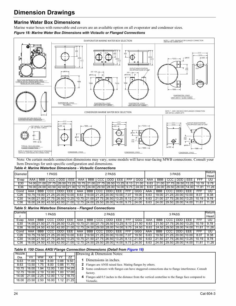
Marine Water Box DimensionsMarine water boxes with removable end covers are an available option on all evaporator and condenser sizes. Figure 18: Marine Water Box Dimensions with Victaulic or Flanged Connections
Table 5: Marine Waterbox Dimensions - Flanged Connections
Table 6: 150 Class ANSI Flange Connection Dimensions (Detail from Figure 18)
Table 4: Marine Waterbox Dimensions - Victaulic Connections
Diameter 1 PASS 2 PASS 3 PASSReturn Head
Evap AAA BBB CCC DDD EEE AAA BBB CCC DDD EEE FFF GGG AAA BBB CCC DDD EEE FFF UUE30 14.00 21.00 27.75 26.50 13.25 10.75 21.00 27.75 26.50 13.25 8.13 21.00 6.63 21.00 27.75 26.50 13.25 10.19 9.78E36 16.00 24.00 43.50 42.00 21.00 12.75 24.00 29.50 28.00 14.00 9.75 24.00 8.63 24.00 29.50 28.00 14.00 11.81 11.26
Cond AAA BBB CCC DDD EEE AAA BBB CCC DDD EEE FFF GGG AAA BBB CCC DDD EEE FFF UUC26 10.75 19.00 21.25 20.00 10.00 8.63 19.00 21.25 20.00 10.00 7.07 19.00 6.63 19.00 21.25 20.00 10.00 8.07 8.38C30 14.00 21.00 27.75 26.50 13.25 10.75 21.00 27.75 26.50 13.25 8.13 21.00 6.63 21.00 27.75 26.50 13.25 10.19 9.78C36 16.00 24.00 43.50 42.00 21.00 12.75 24.00 29.50 28.00 14.00 9.75 24.00 8.63 24.00 29.50 28.00 14.00 11.81 11.26
Diameter
1 PASS 2 PASS 3 PASSReturn Head
Evap AAA BBB CCC DDD EEE AAA BBB CCC DDD EEE FFF GGG AAA BBB CCC DDD EEE FFF UUE30 14.00 21.50 27.75 26.50 13.25 10.75 21.50 27.75 26.50 13.25 8.13 21.50 6.63 21.50 27.75 26.50 13.25 10.19 9.78E36 16.00 24.50 43.50 42.00 21.00 12.75 24.50 29.50 28.00 14.00 9.75 24.50 8.63 24.50 29.50 28.00 14.00 11.81 11.26
Cond AAA BBB CCC DDD EEE AAA BBB CCC DDD EEE FFF GGG AAA BBB CCC DDD EEE FFF UUC26 10.75 19.50 21.25 20.00 10.00 8.63 19.50 21.25 20.00 10.00 7.07 19.50 6.63 19.50 21.25 20.00 10.00 8.07 8.38C30 14.00 21.50 27.75 26.50 13.25 10.75 21.50 27.75 26.50 13.25 8.13 21.50 6.63 21.50 27.75 26.50 13.25 10.19 9.78C36 16.00 24.50 43.50 42.00 21.00 12.75 24.50 29.50 28.00 14.00 9.75 24.50 8.63 24.50 29.50 28.00 14.00 11.81 11.26
NozzleDia.
Drawing & Dimension Notes:
1 Dimensions in inches.2 Flanges are ANSI raised face. Mating flanges by others.3 Some condensers with flanges can have staggered connections due to flange interference. Consult
factory.4 Flanges add 0.5 inches to the distance from the vertical centerline to the flange face compared to
Victaulic.
VV WW XX YY ZZ6.63 11.00 1.56 8.00 0.88 9.508.63 13.50 1.75 8.00 0.88 11.75
10.75 16.00 1.94 12.00 1.00 14.2512.75 19.00 2.19 12.00 1.00 17.0014.00 21.00 2.25 12.00 1.12 18.75
16.00 23.50 2.50 16.00 1.12 21.25
ON "ZZ" BOLT CIRCLE"XX" HOLES, "YY" DIAMETER
TYPICAL 150 CLASS ANSIFLANGE CONNECTION
NOTE: FLANGE BOLT HOLES MUST STRADDLEVERTICAL CENTERLINE ON CONNECTIONS
WW
VV
STANDARD RETURN HEAD FOREVAPORATOR AND CONDENSER
UU
*BBB
AAA
EVAPORATOR, 1 PASSALL UNITS
*BBB *GGG
FFF TYP.
AAA
EVAPORATOR, 2 PASSUNITS WITH 3/4" TUBING
AAA
*BBB
FFF
EVAPORATOR, 3 PASSUNITS WITH 3/4" TUBING
OUTLET HEAD POSITIONON OPPOSITE END OF UNIT
EEE
DDD
CCCDDD
EEE
CCC
OUTIN EEE
DDDCCC
IN
TYP.FFF
AAA*GGG
*BBB
EVAPORATOR, 2 PASSUNITS WITH 1" & MIX TUBING
EEE
DDD
CCC
OUT
IN
*BBB
AAA
CONDENSER, 1 PASS
*GGG
*BBB
TYP.FFF
AAA
CONDENSER, 2 PASS
AAA
TYP.FFF
*BBB
CONDENSER, 3 PASS
OUTLET HEAD POSITIONON OPPOSITE END OF UNIT
EEE
DDD
CCC
EEEDDDCCC
IN
OUT
EEE
DDDCCC
IN
NOTE: * - ADD .500 INCH FOR FLANGED CONNECTION(SEE DETAIL LOWER LEFT)EVAPORATOR MARINE WATER BOX SELECTION
CONDENSER MARINE WATER BOX SELECTION NOTE: * - ADD .500 INCH FOR FLANGED CONNECTION(SEE DETAIL LOWER LEFT)
RIGHT END REPRESENTATIVE VIEW( TYPICAL OF ALL STACKS WITH 2 PASS
HEADS & 3/4" EVAP TUBES )
Note: On certain models connection dimensions may vary; some models will have rear-facing MWB connections. Consult yourItem Drawings for unit-specific configuration and dimensions.
24 Cat 604-3
Dimension Drawings
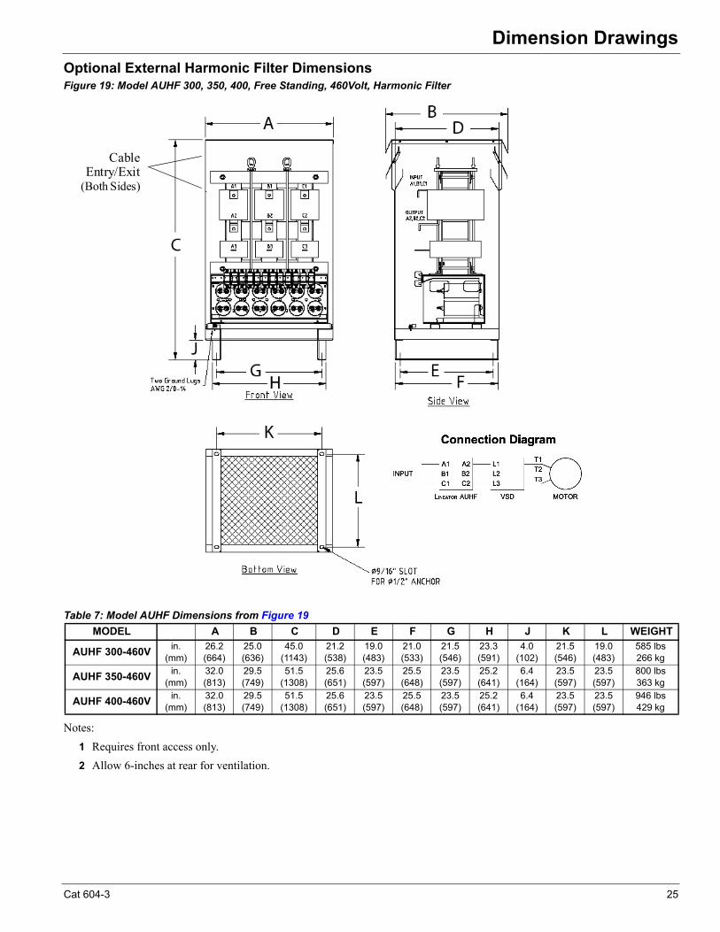
Optional External Harmonic Filter Dimensions Figure 19: Model AUHF 300, 350, 400, Free Standing, 460Volt, Harmonic Filter
Table 7: Model AUHF Dimensions from Figure 19
Notes:
1 Requires front access only.
2 Allow 6-inches at rear for ventilation.
MODEL A B C D E F G H J K L WEIGHT
AUHF 300-460Vin.
(mm)26.2(664)
25.0(636)
45.0(1143)
21.2(538)
19.0(483)
21.0(533)
21.5(546)
23.3(591)
4.0(102)
21.5(546)
19.0(483)
585 lbs266 kg
AUHF 350-460Vin.
(mm)32.0(813)
29.5(749)
51.5(1308)
25.6(651)
23.5(597)
25.5(648)
23.5(597)
25.2(641)
6.4(164)
23.5(597)
23.5(597)
800 lbs363 kg
AUHF 400-460Vin.
(mm)32.0(813)
29.5(749)
51.5(1308)
25.6(651)
23.5(597)
25.5(648)
23.5(597)
25.2(641)
6.4(164)
23.5(597)
23.5(597)
946 lbs429 kg
Cable Entry/Exit
(Both Sides)
Cat 604-3 25
Dimension Drawings
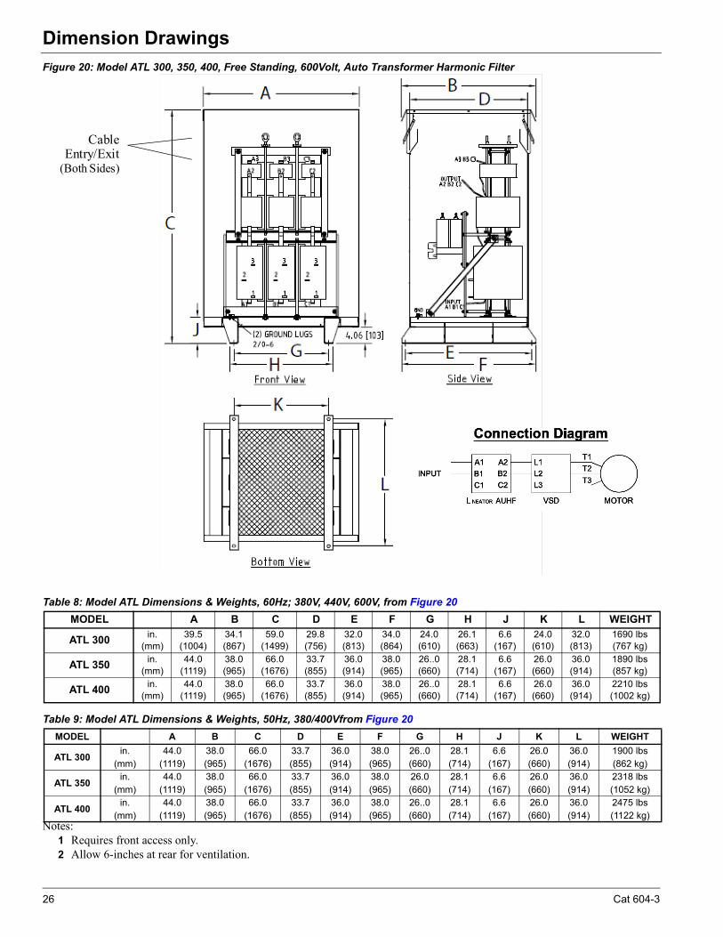
Figure 20: Model ATL 300, 350, 400, Free Standing, 600Volt, Auto Transformer Harmonic Filter
Table 8: Model ATL Dimensions & Weights, 60Hz; 380V, 440V, 600V, from Figure 20
Table 9: Model ATL Dimensions & Weights, 50Hz, 380/400Vfrom Figure 20
Notes:1 Requires front access only.2 Allow 6-inches at rear for ventilation.
MODEL A B C D E F G H J K L WEIGHT
ATL 300in.
(mm)39.5
(1004)34.1(867)
59.0(1499)
29.8(756)
32.0(813)
34.0(864)
24.0(610)
26.1(663)
6.6(167)
24.0(610)
32.0(813)
1690 lbs(767 kg)
ATL 350in.
(mm)44.0
(1119)38.0(965)
66.0(1676)
33.7(855)
36.0(914)
38.0(965)
26..0(660)
28.1(714)
6.6(167)
26.0(660)
36.0(914)
1890 lbs(857 kg)
ATL 400in.
(mm)44.0
(1119)38.0(965)
66.0(1676)
33.7(855)
36.0(914)
38.0(965)
26..0(660)
28.1(714)
6.6(167)
26.0(660)
36.0(914)
2210 lbs(1002 kg)
MODEL A B C D E F G H J K L WEIGHT
ATL 300in.
(mm)44.0
(1119)38.0(965)
66.0(1676)
33.7(855)
36.0(914)
38.0(965)
26..0(660)
28.1(714)
6.6(167)
26.0(660)
36.0(914)
1900 lbs(862 kg)
ATL 350in.
(mm)44.0
(1119)38.0(965)
66.0(1676)
33.7(855)
36.0(914)
38.0(965)
26.0(660)
28.1(714)
6.6(167)
26.0(660)
36.0(914)
2318 lbs(1052 kg)
ATL 400in.
(mm)44.0
(1119)38.0(965)
66.0(1676)
33.7(855)
36.0(914)
38.0(965)
26..0(660)
28.1(714)
6.6(167)
26.0(660)
36.0(914)
2475 lbs(1122 kg)
Cable Entry/Exit
(Both Sides)
26 Cat 604-3
Physical Data & Weights
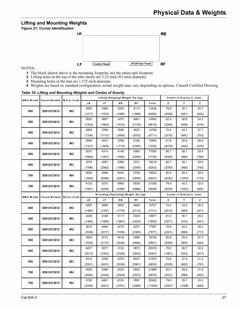
Physical Data & WeightsLifting and Mounting WeightsFigure 21: Corner Identification
NOTES: 1 The block shown above is the mounting footprint, not the entire unit footprint.2 Lifting holes in the top of the tube sheets are 3.25-inch (83 mm) diameter. 3 Mounting holes in the feet are 1.125-inch diameter. 4 Weights are based on standard configuration; actual weight may vary depending on options. Consult Certified Drawing
Table 10: Lifting and Mounting Weights and Centes of Gravity
LB LF R B R F T o ta l X Y Z
2682 3380 3263 4113 13438 79.8 35.1 25.7
(1217) (1533) (1480) (1866) (6095) (2028) (891) (652)
2652 3667 3472 4801 14592 82.5 36.6 24.3
(1203) (1663) (1575) (2178) (6619) (2094) (929) (618)
2953 3769 3546 4527 14795 79.4 34.7 27.7
(1339) (1710) (1609) (2053) (6711) (2016) (881) (703)
2948 4031 3789 5182 15950 81.8 36.4 26.6
(1337) (1829) (1719) (2350) (7235) (2078) (924) (676)
3537 4314 4149 5060 17060 80.7 38.1 29.9
(1604) (1957) (1882) (2295) (7738) (2050) (969) (760)
3519 4591 4385 5721 18216 80.7 38.1 29.9
(1596) (2082) (1989) (2595) (8263) (2050) (969) (760)
3635 4598 4543 5746 18522 80.8 39.4 30.5
(1649) (2086) (2061) (2606) (8401) (2052) (1000) (774)
4102 5370 4995 6539 21006 79.9 40.2 32.5
(1861) (2436) (2266) (2966) (9528) (2028) (1022) (825)
LB LF R B R F T o ta l X Y Z
3263 3896 3902 4660 15721 79.2 34.8 26.4
(1480) (1767) (1770) (2114) (7131) (2012) (883) (671)
3228 4189 4117 5343 16877 81.5 36.1 25.2
(1464) (1900) (1867) (2424) (7655) (2071) (916) (641)
3612 4446 4272 5257 17587 78.8 34.2 28.2
(1638) (2017) (1938) (2385) (7977) (2001) (868) (717)
3604 4712 4518 5908 18742 80.9 35.6 27.3
(1635) (2137) (2049) (2680) (8501) (2055) (905) (693)
4437 5077 5132 5872 20518 78.0 36.7 32.2
(2013) (2303) (2328) (2663) (9307) (1981) (933) (817)
4412 5359 5374 6527 21672 79.9 37.9 31.2
(2001) (2431) (2438) (2961) (9830) (2028) (962) (791)
4529 5366 5532 6553 21980 80.0 38.9 31.6
(2054) (2434) (2509) (2972) (9970) (2031) (989) (802)
5150 6461 6130 7691 25432 79.0 39.7 33.3
(2336) (2931) (2781) (3489) (11536) (2007) (1008) (845)
700 E3612/C3012 M4
700 E3612/C3612 M4
500 E3612/C3012 M2
500 E3612/C3012 M3
500 E3012/C3012 M2
500 E3012/C3012 M3
500 E3012/C2612 M3
WM E M o del Vessel M o dels M o to r C o deM o unt ing (Operat ing) Weight , lbs (kg) C enter o f Grav ity in. (mm)
500 E3012/C2612 M2
700 E3612/C3012 M4
700 E3612/C3612 M4
500 E3612/C3012 M3
500 E3612/C3012 M2
500 E3012/C3012 M2
500 E3012/C3012 M3
500 E3012/C2612 M3
WM E M o del Vessel M o dels M o to r C o deLif t ing (Shipping) Weight , lbs (kg) C enter o f Grav ity in. (mm)
500 E3012/C2612 M2
Cat 604-3 27
Physical Data & Weights
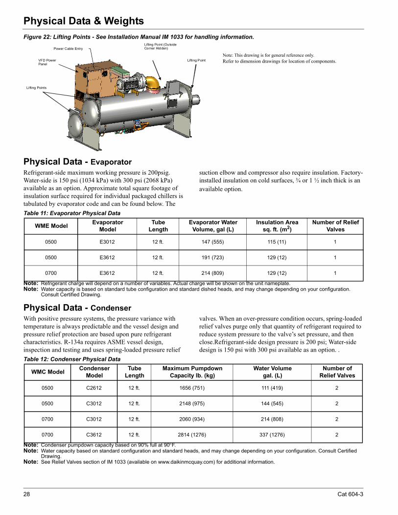
Figure 22: Lifting Points - See Installation Manual IM 1033 for handling information.
Physical Data - Evaporator Refrigerant-side maximum working pressure is 200psig. Water-side is 150 psi (1034 kPa) with 300 psi (2068 kPa) available as an option. Approximate total square footage of insulation surface required for individual packaged chillers is tabulated by evaporator code and can be found below. The
suction elbow and compressor also require insulation. Factory-installed insulation on cold surfaces, ¾ or 1 ½ inch thick is an available option.
Note: Refrigerant charge will depend on a number of variables. Actual charge will be shown on the unit nameplate.Note: Water capacity is based on standard tube configuration and standard dished heads, and may change depending on your configuration.
Consult Certified Drawing.
Physical Data - CondenserWith positive pressure systems, the pressure variance with temperature is always predictable and the vessel design and pressure relief protection are based upon pure refrigerant characteristics. R-134a requires ASME vessel design, inspection and testing and uses spring-loaded pressure relief
valves. When an over-pressure condition occurs, spring-loaded relief valves purge only that quantity of refrigerant required to reduce system pressure to the valve’s set pressure, and then close.Refrigerant-side design pressure is 200 psi; Water-side design is 150 psi with 300 psi available as an option. .
Note: Condenser pumpdown capacity based on 90% full at 90F.Note: Water capacity based on standard configuration and standard heads, and may change depending on your configuration. Consult Certified
Drawing. Note: See Relief Valves section of IM 1033 (available on www.daikinmcquay.com) for additional information.
Li fting Points
Lifting Point
Lifting Point (Outside Corner Hidden)
VFD Power Panel
Power Cable Entry
Note: This drawing is for general reference only.Refer to dimension drawings for location of components.
Table 11: Evaporator Physical Data
WME ModelEvaporator
ModelTube
LengthEvaporator Water
Volume, gal (L)Insulation Area
sq. ft. (m2)Number of Relief
Valves
0500 E3012 12 ft. 147 (555) 115 (11) 1
0500 E3612 12 ft. 191 (723) 129 (12) 1
0700 E3612 12 ft. 214 (809) 129 (12) 1
Table 12: Condenser Physical Data
WMC ModelCondenser
ModelTube
LengthMaximum Pumpdown
Capacity lb. (kg)Water Volume
gal. (L)Number of
Relief Valves
0500 C2612 12 ft. 1656 (751) 111 (419) 2
0500 C3012 12 ft. 2148 (975) 144 (545) 2
0700 C3012 12 ft. 2060 (934) 214 (808) 2
0700 C3612 12 ft. 2814 (1276) 337 (1276) 2
28 Cat 604-3
Refrigeration Diagram
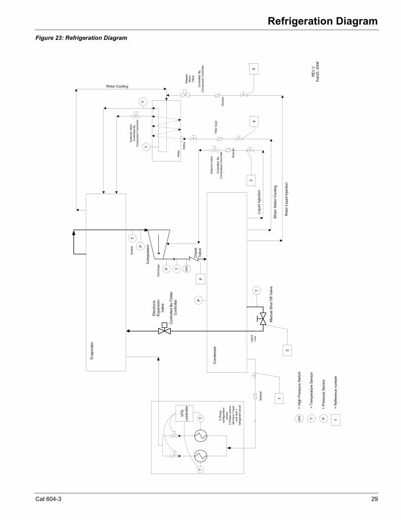
Refrigeration DiagramFigure 23: Refrigeration Diagram
Liqu
id In
ject
ion
Mot
or S
tato
r Coo
ling
Rotor Cooling
Ste
pper
Mot
orVa
lve
Con
trolle
d B
y C
ompr
esso
r Con
trolle
r
Rot
or L
iqui
d In
ject
ion
Ele
ctro
nic
Exp
ansi
on
Val
ve
Con
trolle
d B
y C
hille
r C
ontro
ller
Che
ckV
alve
Man
ual S
hut O
ff V
alve
TVFD
co
ntro
ller
T
Filte
r Dry
er
Stra
iner
Stra
iner
Sole
noid
Val
veC
ontro
lled
By
Com
pres
sor C
ontro
ller
Sole
noid
Val
ve
Con
trolle
d B
y C
ompr
esso
r Con
trolle
r
Stra
iner
T
P
T HPS
T
Suct
ion
Dis
char
ge
Mot
or
Eva
pora
tor
Con
dens
er
Com
pres
sor
RE
V 2
Feb2
0, 2
008
Liqu
idLi
ne
T=
Tem
pera
ture
Sen
sor
P=
Pre
ssur
e S
enso
r
1
2
54
3
1=
Ref
eren
ce n
umbe
r
P
P
TT
HP
S=
Hig
h P
ress
ure
Switc
h
6
Orif
ice
6 Ph
ase
conf
igur
atio
n sh
own.
3
Phas
e ve
rsio
n w
ill ha
ve 1
hea
t si
nk a
nd 1
re
frige
rant
circ
uit
Cat 604-3 29
Application Considerations
Application ConsiderationsLocation Requirements
Daikin McQuay Magnitude units are designed only for indoor, weather-protected, non-freezing area consistent with the NEMA 1 rating on the chiller, controls, and electrical panels. Equipment room temperature for operating and standby conditions is 40°F to 104°F (4.4°C to 40°C).
Optimum Water Temperatures and Flow
A key to improving energy efficiency for any chiller is minimizing the compressor pressure lift. Reducing the lift reduces the compressor work and its energy consumption per unit of output. The chiller typically consumes more energy than any other component in the chiller system. Therefore, the optimum plant design must take into account all of the interactions between chiller, pumps, and tower.
Higher Leaving Chilled Water Temperatures
Warmer leaving chilled water temperatures will raise the compressor's suction pressure and decrease the lift, improving efficiency. Using 45°F (7°C) leaving water instead of 42°F (5.5°C) will significantly reduce chiller energy consumption.
Evaporator Temperature Drop
The industry standard has been a 10°F (5.5°C) temperature drop in the evaporator. Increasing the drop to 12°F or 14°F (6.6°C or 7.7°C)will improve the evaporator heat transfer, raise the suction pressure, and improve chiller efficiency. Chilled water pump energy will also be reduced.
Reduced Evaporator Fluid Flow
Several popular chiller plant control practices including Variable Primary Flow systems advocate reducing the evaporator fluid flow rate as the chiller capacity is reduced. This practice can significantly reduce the evaporator pumping power while having little effect on chiller energy consumption. The Magnitude chiller can operate effectively in variable evaporator flow systems as long as the minimum and maximum tube velocities are taken into consideration when selecting the chiller. See section Variable Fluid Flow Rates and Tube Velocities‚ page 32.
If it is decided to vary the evaporator water flow rate the rate of change should not exceed 50% per minute and should not exceed the minimum or maximum velocity limits.
Condenser Entering Water Temperature
As a general rule, a 1°F (0.5°C) drop in condenser entering water temperature will reduce chiller energy consumption by two percent. Cooler water lowers the condensing pressure and reduces compressor work. One or two degrees can make a
noticeable difference. The incremental cost of a larger tower can be small and provide a good return on investment.
Condenser Water Temperature Rise
The industry standard of 3 gpm/ton or about a 9.5°F (5.3°C) delta-T seems to work well for most applications.
Reduced Condenser Fluid Flow
Several popular chiller plant control practices also advocate reducing the condenser fluid flow rate as the chiller load is reduced. This practice can significantly reduce the condenser pumping power, but it may also have the unintended consequence of significantly increasing compressor power since the leaving condenser water temperature is directly related to compressor lift and power. The higher compressor power will typically be larger than the condenser pumping power reduction and will result in a net increase in chiller plant energy consumption. Therefore, before this strategy is applied for energy saving purposes it should be extensively modeled or used in an adaptive chiller plant control system which will take into account all of the interdependent variables affecting chiller plant energy. If it is decided to use variable condenser fluid flow, the Magnitude chiller can operate effectively as long as the minimum and maximum tube velocities are taken into consideration when selecting the chiller.
Chilled Water Temperature
The maximum temperature of water entering the chiller on standby must not exceed 105°F (46.1°C). Maximum temperature entering on start-up must not exceed 90°F (32°C). Minimum chilled water leaving temperature without antifreeze is approximately 38°F (3.3°C).
Piping
Piping must be adequately supported to remove weight and strain on the chiller's fittings and connections. Be sure piping is adequately insulated for job conditions. Install a cleanable 20-mesh water strainer upstream of the evaporator and condenser. Install enough shutoff valves to permit draining water from the evaporator or condenser without draining the complete system.
Note: This product is equipped with a shell and tube evaporator with carbon steel shell and copper tubes. The water or other fluid used in these evaporators must be clean and non-corrosive to the materials used in the evaporator. Non-compatible fluids can void the equipment warranty. If the compatibility of the fluid with the evaporator is in question, a professional water quality consultant should administer the proper testing and evaluate compatibility.
30 Cat 604-3
Application Considerations
Condenser Water Temperature
When the ambient wet bulb temperature is lower than design, the entering condenser water temperature of Magnitude WME chillers can be lowered to improve chiller performance.
Chillers can start with entering condenser water temperatures as low as 40°F (4.4°C). For short periods of time during startup, the entering condenser water temperature can even be lower than the leaving chilled water temperature.
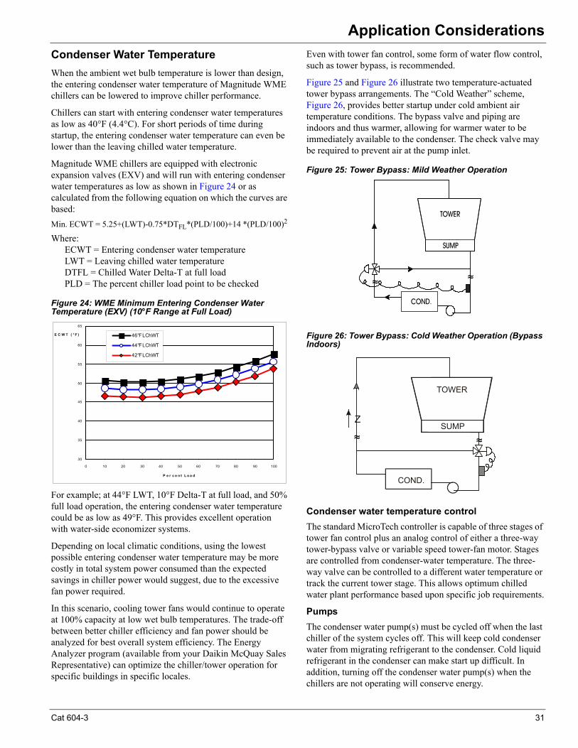
Magnitude WME chillers are equipped with electronic expansion valves (EXV) and will run with entering condenser water temperatures as low as shown in Figure 24 or as calculated from the following equation on which the curves are based:
Min. ECWT = 5.25+(LWT)-0.75*DTFL*(PLD/100)+14 *(PLD/100)2
Where:ECWT = Entering condenser water temperatureLWT = Leaving chilled water temperatureDTFL = Chilled Water Delta-T at full loadPLD = The percent chiller load point to be checked
Figure 24: WME Minimum Entering Condenser Water Temperature (EXV) (10°F Range at Full Load)
For example; at 44°F LWT, 10°F Delta-T at full load, and 50% full load operation, the entering condenser water temperature could be as low as 49°F. This provides excellent operation with water-side economizer systems.
Depending on local climatic conditions, using the lowest possible entering condenser water temperature may be more costly in total system power consumed than the expected savings in chiller power would suggest, due to the excessive fan power required.
In this scenario, cooling tower fans would continue to operate at 100% capacity at low wet bulb temperatures. The trade-off between better chiller efficiency and fan power should be analyzed for best overall system efficiency. The Energy Analyzer program (available from your Daikin McQuay Sales Representative) can optimize the chiller/tower operation for specific buildings in specific locales.
Even with tower fan control, some form of water flow control, such as tower bypass, is recommended.
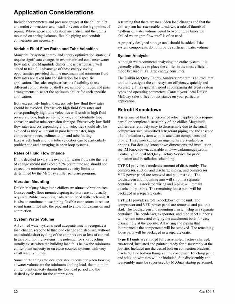
Figure 25 and Figure 26 illustrate two temperature-actuated tower bypass arrangements. The “Cold Weather” scheme, Figure 26, provides better startup under cold ambient air temperature conditions. The bypass valve and piping are indoors and thus warmer, allowing for warmer water to be immediately available to the condenser. The check valve may be required to prevent air at the pump inlet.
Figure 25: Tower Bypass: Mild Weather Operation
Figure 26: Tower Bypass: Cold Weather Operation (Bypass Indoors)
Condenser water temperature control
The standard MicroTech controller is capable of three stages of tower fan control plus an analog control of either a three-way tower-bypass valve or variable speed tower-fan motor. Stages are controlled from condenser-water temperature. The three-way valve can be controlled to a different water temperature or track the current tower stage. This allows optimum chilled water plant performance based upon specific job requirements.
Pumps
The condenser water pump(s) must be cycled off when the last chiller of the system cycles off. This will keep cold condenser water from migrating refrigerant to the condenser. Cold liquid refrigerant in the condenser can make start up difficult. In addition, turning off the condenser water pump(s) when the chillers are not operating will conserve energy.
30
35
40
45
50
55
60
65
0 10 20 30 40 50 60 70 80 90 100
P e r c e n t L o a d
E C W T ( ° F ) 46°F LChWT
44°F LChWT
42°F LChWT
�
�
� �
Cat 604-3 31
Application Considerations
Include thermometers and pressure gauges at the chiller inlet and outlet connections and install air vents at the high points of piping. Where noise and vibration are critical and the unit is mounted on spring isolators, flexible piping and conduit connections are necessary.
Variable Fluid Flow Rates and Tube Velocities
Many chiller system control and energy optimization strategies require significant changes in evaporator and condenser water flow rates. The Magnitude chiller line is particularly well suited to take full advantage of these energy saving opportunities provided that the maximum and minimum fluid flow rates are taken into consideration for a specific application. The sales engineer has the flexibility to use different combinations of shell size, number of tubes, and pass arrangements to select the optimum chiller for each specific application.
Both excessively high and excessively low fluid flow rates should be avoided. Excessively high fluid flow rates and correspondingly high tube velocities will result in high fluid pressure drops, high pumping power, and potentially tube corrosion and/or tube corrosion damage. Excessively low fluid flow rates and correspondingly low velocities should also be avoided as they will result in poor heat transfer, high compressor power, sedimentation and tube fouling. Excessively high and low tube velocities can be particularly problematic and damaging in open loop systems.
Rates of Fluid Flow Change
If it is decided to vary the evaporator water flow rate the rate of change should not exceed 50% per minute and should not exceed the minimum or maximum velocity limits as determined by the McQuay chiller software program.
Vibration Mounting
Daikin McQuay Magnitude chillers are almost vibration-free. Consequently, floor mounted spring isolators are not usually required. Rubber mounting pads are shipped with each unit. It is wise to continue to use piping flexible connectors to reduce sound transmitted into the pipe and to allow for expansion and contraction.
System Water Volume
All chilled water systems need adequate time to recognize a load change, respond to that load change and stabilize, without undesirable short cycling of the compressors or loss of control. In air conditioning systems, the potential for short cycling usually exists when the building load falls below the minimum chiller plant capacity or on close-coupled systems with very small water volumes.
Some of the things the designer should consider when looking at water volume are the minimum cooling load, the minimum chiller plant capacity during the low load period and the desired cycle time for the compressors.
Assuming that there are no sudden load changes and that the chiller plant has reasonable turndown, a rule of thumb of “gallons of water volume equal to two to three times the chilled water gpm flow rate” is often used.
A properly designed storage tank should be added if the system components do not provide sufficient water volume.
System Analysis
Although we recommend analyzing the entire system, it is generally effective to place the chiller in the most efficient mode because it is a large energy consumer.
The Daikin McQuay Energy Analyzer program is an excellent tool to investigate the entire system efficiency, quickly and accurately. It is especially good at comparing different system types and operating parameters. Contact your local Daikin McQuay sales office for assistance on your particular application.
Retrofit Knockdown
It is estimated that fifty percent of retrofit applications require partial or complete disassembly of the chiller. Magnitude chillers are relatively easy to disassemble due to the small compressor size, simplified refrigerant piping and the absence of a lubrication system with its attendant components and piping. Three knockdown arrangements are available as options. For detailed knockdown dimensions and installation, see IM Knockdown, available at www.daikinmcquay.com. Contact your local McQuay Factory Service for price quotation and installation scheduling.
TYPE I provides a moderate amount of disassembly. The compressor, suction and discharge piping, and compressor VFD power panel are removed and put on a skid. The touchscreen and mounting arm will ship in a separate container. All associated wiring and piping will remain attached if possible. The remaining loose parts will be packaged in a separate crate.
TYPE II provides a total knockdown of the unit. The compressor and VFD power panel are removed and put on a skid. The touchscreen and mounting arm will ship in a separate container. The condenser, evaporator, and tube sheet supports will remain connected only by the attachment bolts for easy disassembly at the job site. All wiring and piping that interconnects the components will be removed. The remaining loose parts will be packaged in a separate crate.
Type III units are shipped fully assembled, factory charged, run-tested, insulated and painted; ready for disassembly at the job site. Included are the vessel bolt-on connection brackets, discharge line bolt-on flanges at the condenser. Touch-up paint and stick-on wire ties will be included. Site disassembly and reassembly must be supervised by McQuay startup personnel.
32 Cat 604-3
Options and Accessories
Options and AccessoriesUnit Options
Export packaging
Can be either open or closed crate and with optional shipping bag. A wooden skid and a shrink-wrapped bag covering the entire unit and protecting it from possible dirt and grime accumulation during transit are standard.
Pumpout Unit, with or without storage vessel
Available in a variety of sizes, single-phase or three-phase, with and without tanks. Contact your Daikin McQuay sales office for details.
Extended warranties
Extended 1, 2, 3, or 4 year warranties for parts only or for parts and labor are available for the compressor/motor only, the entire unit, or the entire unit including refrigerant.
Spring vibration Isolators
Spring isolators for use in special situations requiring extremely low vibration and sound levels.
Witness performance test
The specified full and/or part load tests, as ordered, are performed in the presence of the customer under the supervision of a factory engineer and include compilation of the test data onto an easy-to-read spreadsheet. Tests are run to AHRI tolerances of capacity and power. Travel and local expenses are not included.
Certified performance test
The specified full and/or part load run tests, as ordered, are performed under the supervision of a factorry engineer; data is compiled, certified and transmitted to the customer. Tests are run to AHRI tolerances of capacity and power
Refrigerant charge
Holding charge of Nitrogen or R-134a. Shipping with a full charge of R-134a is standard.
Knockdown shipment
Several options for a knockdown shipment to facilitate unit placement. See page 32 for details.
Vessel Options
Marine water boxes
Provides tube access for inspection, cleaning, and removal without dismantling water piping.
Flanges (Victaulic connections are standard)
ANSI raised face flanges on either the evaporator or condenser. Mating flanges are by others.
Water side vessel construction of 300 psi (150 psi is standard)
For high pressure water systems, typically high-rise building construction.
Epoxy coating
Evaporator and condenser tube sheets,heads and marine boxes can be epoxy coated for corrossion protection.
Single insulation - evaporator shell / heads / suction piping
0.75-inch insulation on cold surfaces. Insulation, either optional factory-installed or field-installed is required on all installations.
Double insulation - evaporator shell / heads / suction piping
1.5-inch insulation on cold surfaces (0.75-inch on suction piping) for low fluid temperatures and/or high humidity .
Tube size, wall thickness and material
A wide range of tube options are available to accommodate most flow rates and fluids. Standard wall thickness is 0.025 in., optional 0.028 in. or 0.035 in.
Controls Options
BAS interface module
Factory-installed on the unit controller for the applicable protocol being used (Can also be retrofit):
• BACnet MS/TP
• BACnet IP
• BACnet Ethernet
• LonWorks
• Modbus RTU
Electrical Options
High short circuit current rating
35kA, 65 kA and 100kA (at 460V) panel rating available with a matching circuit breaker.
Low Harmonic VFD Option
The Low THD option (M3) model VFD has been tested to meet SEMI F47-0706 standard for voltage sag immunity. This is a standard from the semi-conductor industry that specifies various scenarios regarding voltage sag intensity (percent of voltage remaining during sag) and duration (in cycles or seconds). The chiller will remain on-line during a voltage sag that meets the criteria in this testing protocol.
EMI filter
Factory-installed option. Radio interference filter.
Ground fault protection
Protects equipment from arcing ground fault damage from line-to-ground fault currents less than those required for conductor protection.
Input power meter
Allows display of phase amps and volts on the operator interface screen.
Special Order Options
The following special order options are available; requiring factory pricing, additional engineering and possible dimension changes or extended delivery:
Special Order Options:
1 Non-standard location of nozzle connections on heads (compact water boxes) or marine water boxes
Cat 604-3 33
Options and Accessories
2 Special corrosion inhibiting coatings on any "wetted surface" including tubesheets, heads (compact water boxes), marine water boxes, or nozzles
3 Clad tube sheets
4 Sacrificial anodes in heads (compact water boxes) or marine water boxes
5 Eddy current testing and report used to verify baseline tube condition
6 Special NEMA enclosures
7 Davits or hinges for marine water box covers or heads (compact water boxes)
8 Accelerometer and vibration monitoring pickup mounting )
9 Spacer rings on heads to accommodate automatic tube
10 Brush cleaning systems (installed by others)
11 Field Mounted Harmonic Filter, WME 500, Free-standing, passive harmonic filter Model AUHF for 460 volt service and Model ATL, which includes an autotransformer for 600 volts.
12 Factory-Mounted Harmonic Filter, WME 500, mounted and wired, passive harmonic filter for 460V duty.
13 Refrigerant monitor, for remote mounting including accessories such as 4-20ma signal, strobe light, audible horn, air pick-up filter.
34 Cat 604-3
Engineering Guide Specifications
Engineering Guide SpecificationsSECTION 15XXX: MAGNETIC BEARING CENTRIFUGAL CHILLERS
PART 1 - GENERAL
1.1 SUMMARY
A Section includes design, performance criteria, refrigerants, controls, and installation requirements for water-cooled centrifugal chillers.
1.2 REFERENCES
A Comply with the following codes and standards:
• AHRI 550/590
• AHRI 575
• NEC
• ANSI/ASHRAE 15
• OSHA as adopted by the State
• ETL
• ASME Section VIII
1.3 SUBMITTALS
A Submittals shall include the following:
1 Dimensioned plan and elevation view, including required clearances, and location of all field piping and electrical connections.
2 Summaries of all auxiliary utility requirements such as: electricity, water, air, etc. Summary shall indicate quality and quantity of each required utility.
3 Diagram of control system indicating points for field interface and field connection. Diagram shall fully depict field and factory wiring.
4 Manufacturer's certified performance data at full load plus IPLV or NPLV.
5 Installation and Operating Manuals.
1.4 QUALITY ASSURANCE
A Regulatory Requirements: Comply with the codes and standards in Section 1.2.
B Chiller manufacturer plant shall be ISO Certified.
C The chiller shall be tested to job conditions on an AHRI qualified test stand at the manufacturer's plant.
1.5 DELIVERY AND HANDLING
A Chillers shall be delivered to the job site completely assembled and charged with refrigerant R-134a and be shipped on skids with a weather resistant cover. -- OR --
A (Type I Knockdown, WME only) The compressor, suction and discharge piping, VFD power panel and touchscreen shall be removed and shipped separately. All wiring and piping shall remain attached where possible. The remaining loose parts shall be packaged in a separate crate. The unit is
to be run-tested at the factory and shipped with a helium holding charge, evaporator insulated and a kit for compressor insulation. Contractor shall leak test, evacuate and charge with refrigerant after reassembly.--OR--
A (Type II Knockdown, WME only) The compressor, VFD power panel, wiring and interconnecting piping shall be removed and shipped separately. The unit shall be run-tested at the factory. The compressor and vessels shall ship with a helium holding charge, the evaporator insulated and a kit for compressor insulation included. Contractor shall leak test, evacuate and charge with refrigerant after reassembly.--OR--
A (Type III Knockdown, WME only) The units shall be shipped fully assembled, factory charged, run-tested, insulated and painted; ready for disassembly at the job site. The unit shall have vessel bolt-on connection brackets, discharge line bolt-on flanges at the condenser, touch-up paint and stick-on wire ties. Site disassembly and reassembly must be factory supervised. Contractor shall leak test, evacuate and charge with refrigerant after reassembly.--OR--
A (Type IV Knockdown WMC only) The compressor and VFD power panel shall be removed at the factory and shipped on skids. The stripped vessel stack shall be shipped as a single piece. Discharge piping, liquid line and the compressor cooling lines shall be removed and crated. All associated wiring and piping possible will remain on the vessel stack. The unit shall be shipped with a holding charge of helium. Contractor shall leak test, evacuate and charge with refrigerant after reassembly -- OR --
A (Type V Knockdown, WMC only) The unit shall be delivered to the job site completely assembled and charged with refrigerant (pumped down into condenser) and ready for field knockdown, as determined by the installing contractor. Contractor shall leak test, evacuate and charge with refrigerant after reassembly
B Comply with the manufacturer's instructions for rigging and transporting units. Leave protective covers in place until installation.
1.6 WARRANTY
A The chiller manufacturer's warranty shall cover parts and labor costs for the repair or replacement of defects in material or workmanship for a period of one year from equipment startup or 18 months from shipment, whichever occurs first.-- OR --
A The chiller manufacturer's warranty shall cover parts and labor costs for the repair or replacement of defects in material or workmanship, and include refrigerant for the
Cat 604-3 35
Engineering Guide Specifications
entire unit, for a period of one year from equipment startup or 18 months from shipment, whichever occurs first. OR,
B The chiller manufacturer's warranty shall cover parts and labor costs for the repair or replacement of defects in material or workmanship, and include refrigerant for the entire unit, for a period of one year from equipment startup or 18 months from shipment, whichever occurs first, and also include an additional extended warranty for (one OR two OR three OR four) years on (the entire unit) OR (on entire unit including refrigerant coverage) OR (compressor and drive train only).
1.7 MAINTENANCE
A Maintenance of the chillers in accordance with manufacturer’s recommendations as published in the installation and maintenance manuals, shall be the responsibility of the owner.
PART 2 - PRODUCTS
2.1 ACCEPTABLE MANUFACTURERS
A Basis of Design - Daikin McQuay Magnitude Model WMC/WME, including the standard product features and all special features required per the plans and specifications.
B Equal Products - Equipment manufactured by [ENTER MANUFACTURER NAME HERE] may be acceptable as an equal. Naming these products as equal does not imply that their standard construction or configuration is acceptable or meets the specifications. Equipment proposed “as equal”, must meet the specifications including all architectural, mechanical, electrical, and structural details, all scheduled performance and the job design, plans and specifications.
2.2 UNIT DESCRIPTION
A Provide and install as shown on the plans a factory assembled, charged, and run-tested water-cooled packaged centrifugal chiller. Chillers shall have no more than two oil-free, magnetic bearing, semi-hermetic centrifugal compressors (no exceptions). Each compressor shall have an integrated variable-frequency drive operating in concert with inlet guide vanes for optimized full and part load efficiency. On two-compressor units, the evaporator and condenser refrigerant sides and the expansion valve shall be common and the chiller shall be capable of running on one compressor with the other compressor or any of its auxiliaries inoperable or removed.
Each chiller shall be factory run-tested on an AHRI quali-fied test stand with water at job conditions (excluding gly-col applications). Operating controls shall be adjusted and checked. The refrigerant charge shall be adjusted for opti-mum operation and recorded on the unit nameplate. Units operating with 50-Hz power shall be tested with a 50-Hz
power supply. Any deviation in performance or operation shall be remedied prior to shipment and the init retested if necessary to confirm repairs or adjustments.
2.3 DESIGN REQUIREMENTS
A General: Provide a complete water-cooled, semi-hermetic oil-free centrifugal compressor water chiller as specified herein. The unit shall be provided according to standards indicated in Section 1.2. In general, unit shall consist of one or two magnetic bearing, completely oil-free centrifugal compressors, refrigerant, condenser and evaporator, and control systems including integrated variable frequency drive, operating controls and equipment protection controls. Chillers shall be charged with refrigerant HFC-134a. If manufacturer offers a chiller using any HCFC refrigerant, manufacturer shall provide, in writing, documentation signed by an officer of the company assuring refrigerant availability and price schedule for a 20-year period.
B The entire chiller system, including all pressure vessels, shall remain above atmospheric pressure during all operating conditions and during shut down to ensure that non-condensables and moisture do not contaminate the refrigerant and chiller system. If any portion of the chiller system is below atmospheric pressure during either operation or shut down, the manufacturer shall include, at no charge:
1 A 20-year purge maintenance agreement that provides parts, labor, and all preventative maintenance required by the manufacturer’s operating and maintenance instructions.
2 A complete purge system capable of removing non-condensables and moisture during operation and shut-down.
3 The manufacturer shall also include at no charge for a period of 20 years an annual oil and refrigerant analysis report to identify chiller contamination due to vacuum leaks. If the analysis identifies water, acid, or other contaminant levels higher than specified by the manufacturer, the oil and/or refrigerant must be replaced or returned to the manufacturer’s original specification at no cost to the owner.
4 The manufacturer shall include a factory-installed and wired system that will enable service personnel to readily elevate the vessel pressure during shutdown to facilitate leak testing.
C Performance: Refer to chiller performance rating.
D Acoustics: Sound pressure for the unit shall not exceed the following specified levels. Provide the necessary acoustic treatment to chiller as required. Sound data shall be measured in dB according to AHRI Standard 575 and shall
36 Cat 604-3
Engineering Guide Specifications
include overall dBA. Data shall be the highest levels recorded at all load points.
2.4 CHILLER COMPONENTS
A Compressors:
1 The unit shall utilize magnetic bearing, oil-free, semi-hermetic centrifugal compressors. The compressor drive train shall be capable of coming to a controlled, safe stop in the event of a power failure.
2 The motor shall be of the semi-hermetic type, of sufficient size to efficiently fulfill compressor horsepower requirements. It shall be liquid refrigerant cooled with internal thermal sensing devices in the stator windings. The motor shall be compatible with variable frequency drive operation.
a If the compressor design requires a shaft seal to contain the refrigerant, the manufacturer shall supply a 20 year parts and labor warranty on the shaft seal and a lifetime refrigerant replacement warranty if a seal failure leads to refrigerant loss, or the chiller manufacturer shall assume all costs to supply and install a self contained air conditioning system in the mechanical space sized to handle the maximum heat output the open drive motor. The energy required to operate this air conditioning system shall be added to the chiller power at all rating points for energy evaluation purposes.
3 The chiller shall be equipped with an integrated Variable Frequency Drive (VFD) to automatically regulate compressor speed in response to cooling load and the compressor pressure lift requirement. Movable inlet guide vanes and variable compressor speed, shall provide unloading. The chiller controls shall coordinate compressor speed and guide vane position to optimize chiller efficiency.
4 Each compressor circuit shall be equipped with a line reactor to help protect against incoming power surges and help reduce harmonic distortion.
5 [OPTION} WME 500, each compressor shall be equipped with a factory-mounted and wired 460Vpassive harmonic filter. It shalll be guaranteed to meet the IEEE Standard 519 for harmonic levels for this application.,
[OPTION} WME 500, each compressor shall be supplied with a 460V/575V passive harmonic filter for field-mounting and wiring . It shalll be guaranteed to meet the IEEE Standard 519 for Isc/IL harmonic levels for this application
6 Evaporator and Condenser:
1 The evaporator and condenser shall be separate vessels of the shell-and-tube type, designed, constructed, tested
and stamped according to the requirements of the ASME Code, Section VIII. The tubes shall be individually replaceable and secured to the intermediate supports without rolling.
2 The evaporator shall be flooded type with [0.025 in.] OR [0.028 in.] OR [0.035 in.] wall, copper tubes rolled into carbon steel tubesheets. The water side shall be designed for a minimum of [150 psi] OR [250 psi] OR [350 psi]. The evaporator shall have [dished heads] OR [ marine water boxes with removable covers] and shall be [carbon steel] OR [epoxy-coated steel]]. Water connections shall be [grooved suitable for Victaulic couplings] OR [flanged connections]. The evaporator shall have [right-hand] OR [left-hand] connections when looking at the unit control panel.
3 The condenser shall have [0.025 in.] OR [0.028 in.] OR [0.035 in.] wall copper tubes rolled into carbon steel. Water connections shall be [grooved suitable for Victaulic couplings] OR [flanged]. The water side shall be designed for a minimum of [150 psi] OR [250 psi] OR [350 psi]. The condenser shall have [dished heads with valved drain and vent connections] OR [marine water boxes with removable covers and vent and drain connections]. The condenser shall have [right-hand] OR [left-hand] connections when looking at the unit control panel.
4 Provide sufficient isolation valves and condenser volume to hold the full unit refrigerant charge in the condenser during servicing or provide a separate pumpout system and storage tank sufficient to hold the charge of the largest unit being furnished.
5 An electronic expansion valve shall control refrigerant flow to the evaporator. Fixed orifice devices or float controls with hot gas bypass are not acceptable because of inefficient control at low load conditions. The liquid line shall have moisture indicating sight glass.
6 Re-seating type spring loaded pressure relief valves according to ASHRAE-15 safety code shall be furnished. The evaporator shall be provided with single or multiple valves. The condenser shall be provided with dual relief valves equipped with a transfer valve so one relief valve can be removed for testing or replacement without loss of refrigerant or removal of refrigerant from the condenser. Rupture disks are not acceptable.
7 The evaporator, [return water head] OR [return and connection water heads], suction line, and any other component or part of a component subject to condensing moisture shall be insulated with UL recognized 3/4 inch OR 1 ½ inch closed cell insulation. All joints and seams shall be carefully sealed to form a vapor barrier.The discharge line shall be factory insulated.
8 Provide factory-mounted and wired, thermal-dispersion water flow switches on each vessel to prevent unit operation with no or low water flow.
Octave Band OveralldBA63 125 250 500 1000 2000 4000 8000
Cat 604-3 37
Engineering Guide Specifications
B Vibrations
1 Provide neoprene waffle-type vibration isolators for each corner of the unit.
C Unit shall be bagged and mounted on skids for shipment.
D Power Connections
• Power connection shall be single point to a factory-mounted disconnect switch OR shall be multipoint to each compressor power panel on two-compressor units.
E Chiller Control
1 The unit shall have a microprocessor-based control system consisting of a 15-inch VGA touch-screen operator interface and a unit controller.
2 The touch-screen shall display the unit operating parameters, accept setpoint changes (multi-level password protected) and be capable of resetting faults and alarms. The following parameters shall be displayed on the home screen and also as trend curves on the trend screen:
• Entering and leaving chilled water temperatures
• Entering and leaving condenser water temperatures
• Evaporator saturated refrigerant pressure
• Condenser saturated refrigerant pressure
• Percent of 100% speed (per compressor)
• % of rated load amps for entire unit
3 In addition to the trended items above, all other important real-time operating parameters shall also be shown on the touch-screen. These items shall be displayed on a chiller graphic showing each component. At a minimum, the following critical areas must be monitored:
• Compressor actual speed, maximum speed, percent speed
• Evaporator water in and out temperatures, refrigerant pressure and temperature
• Condenser water in and out temperatures, refrigerant pressure and temperature
• Liquid line temperature
• Chilled water setpoint
• Compressor and unit state and input and output digital and analog values
4 A fault history shall be displayed using an easy to decipher, color coded set of messages that are date and time stamped. The alarm history shall be downloadable from the unit's USB port. An operating and maintenance manual specific for the unit shall be viewable on the screen.
5 All setpoints shall be viewable and changeable (multi-level password protected) on the touch screen and include setpoint description and range of set values.
6 Automatic corrective action to reduce unnecessary cycling shall be accomplished through preemptive control of low evaporator or high discharge pressure conditions to keep the unit operating through abnormal transient conditions.
7 The chiller shall be capable of cycling and loading up to seven other similar chillers through a local network and also provide automatic control of: evaporator and condenser pumps (primary and standby), up to 3 stages of cooling tower fan cycling control and a tower modulating bypass valve or cooling tower fan variable frequency drive.
8 Optionally, the factory mounted controller(s) shall support operation on a BACnet®, Modbus® or LONWORKS® network via one of the data link / physical layers listed below as specified by the successful Building Automation System (BAS) supplier.
• Modbus
• BACnet MS/TP master (Clause 9)
• BACnet IP, (Annex J)
• BACnet ISO 8802-3, (Ethernet)
• LonTalk® FTT-10A. The unit controller shall be LON-MARK ® certified.
9 The information communicated between the BAS and the factory mounted unit controllers shall include the reading and writing of data to allow unit monitoring, control and alarm notification as specified in the unit sequence of operation and the unit points list.
10 For chillers communicating over a LONMARK network, the corresponding LONMARK eXternal Interface File (XIF) shall be provided with the chiller submittal data.
11 All communication from the chiller unit controller as specified in the points list shall be via standard BACnet objects. Proprietary BACnet objects shall not be allowed. BACnet communications shall conform to the BACnet protocol (ANSI/ASHRAE135-2001). A BACnet Protocol Implementation Conformance Statement (PICS) shall be provided along with the unit submittal.
2.5. OPTIONAL ITEMS
A The following optional items shall be furnished:
1 [Open crate] OR [Open crate with bag] OR [totally enclosed export crate] OR [totally enclosed export crate with bag]
2 Pumpout unit, with or without storage vessel
3 Refrigerant monitor
4 IBC Certification: The chiller shall be certified to the following codes and standards; 2009 IBC, 2010 CBC, ICC-ES AC-156, ASCE 7-05. The chiller must be mounted to a rigid base and may use r neoprene pads.
5 OSHPD Certification: The chiller shall be OSHPD Pre-Approved per OSP-0116-10 and be so labeled. The
38 Cat 604-3
Engineering Guide Specifications
chiller shall meet a minimum seismic design spectral response acceleration of 1.60 SDS. The chiller must be mounted to a rigid base and may use neoprene waffle vibration pads.
6 Certified performance test in accordance with procedures and to the tolerances contained in AHRI Standard 550/590.
-- OR --
6 Witness performance test in accordance with procedures and to the tolerances contained in AHRI Standard 550/590.
PART 3 - EXECUTION
3.1 INSTALLATION
A installing contractor to:
1 Install per manufacturer's requirements, shop drawings, and contract documents.
2 Adjust chiller alignment on foundations, or subbases as called for on drawings.
3 Arrange piping to allow for dismantling to permit head removal and tube cleaning.
4 Coordinate electrical installation with electrical contractor.
5 Coordinate controls with control contractor.
6 Provide all material required for a fully operational and functional chiller.
3.2 START-UP
A Factory Start-Up Services: Provide for as long a time as is necessary to ensure proper operation of the unit, but in no case for less than two full working days. During the period of start-up, the start-up technician shall instruct the owner's representative in proper care and operation of the unit.
Cat 604-3 39
Engineering Guide Specifications
40 Cat 604-3

© 2012 McQuay International • www.daikinmcquay.com • 800-432-1342 07/12
McQuay Training and Development
Now that you have made an investment in modern, efficient Daikin McQuay equipment, its care should be a high priority. For training information on all Daikin McQuay HVAC products, please visit www.daikinmcquay.com and click on training, or call 540-248-9646 to speak with the Training Department.
Warranty
All Daikin McQuay equipment is sold pursuant to its standard terms and conditions of sale, including Limited Product Warranty. Consult your local Daikin McQuay Representative for warranty details. Refer to Form 933-43285Y. To find your local Daikin McQuay Representative, go to www.daikinmcquay.com.
This document contains the most current product information as of this printing. For the most up-to-date product information, please go to www.daikinmcquay.com.


![1110Wilms [Reptilia] 15Nov - WME News](https://static.fdocuments.in/doc/165x107/61fb31cd2e268c58cd5b46c7/1110wilms-reptilia-15nov-wme-news.jpg)