19PV Magnetic Bearing Oil-free Centrifugal Liquid Chiller
18
19PV Magnetic Bearing Oil-free Centrifugal Liquid Chiller Cooling capacity: 100~350RT
Transcript of 19PV Magnetic Bearing Oil-free Centrifugal Liquid Chiller

19PVMagnetic Bearing Oil-freeCentrifugal Liquid ChillerCooling capacity: 100~350RT

In 1998, Time magazine named Dr. Carrier one of its 20 most influential builders and titans of the 20thcentury.
Carrier is a leading global
provider of innovative HVAC,
refrigeration, fire, security and
building automation technolo-
gies. Supported by the iconic
Carrier name, the company’s
portfolio includes industry-
leading brands such as Carrier,
Kidde, Edwards, LenelS2 and
Automated Logic. Carrier ’s
businesses enable modern life,
delivering efficiency, safety,
security, comfort, productivity
and sustainability across a wide
range of residential, commercial
and industrial applications.

2
Nomenclature
19PV BOE 3 8TE 3B N 2
All data over 200Tons (50Hz) and all data (60Hz) in this catalogue is certificated in accordance with AHRIStandard 550/590 and 551/591 as represented in the selection software (E-Cat).Certified units may be found in the AHRI Directory at www.ahridirectory.org
http://www.ahridirectory.org
Input power code1: 380V-3Ph-50Hz 2: 400V-3Ph-50Hz3: 380V-3Ph-60Hz 4: 460V-3Ph-60Hz
Economizer ConfigurationE- With Economizer N- Without EconomizerCondenser water pass, 3- three passesCondenser tube typeCondenser frame & bundle sizeH2, H3, K2, K3, L2, OD, QD, TEEvaporator water pass, 3- three passesEvaporator tube typeEvaporator frame & bundle sizeH2, H3, K2, K3, L2, OC, OD, OECarrier magnetic bearing oil-free centrifugal with VFD
Compressor frame code
Operating Range
CoolingEvaporator Minimum MaximumEntering temperature at start-up - 32℃Leaving temperature during operation 3.3℃ * 20℃Entering/leaving temperature difference at full load 2.8℃ 11.1℃Condenser Minimum MaximumEntering temperature at start-up 8℃ -Leaving temperature during operation 15℃ 45℃Entering/leaving temperature difference at full load 2.8℃ 11.1℃
Notes:1. * If the leaving water temperature is below 3.3℃ , a frost protection solution must be used.2. Within 3 minutes after the start up of the unit, the unit should function inside the operational envelop, a bypass valve should be installed between the condenser water inlet and outlet pipe,
if condenser outlet temperature is between 8℃ and 15℃ .3. During storage and transport of the unit the minimum and maximum permissible temperatures are -20℃ and 60℃ . These temperatures should be taken into consideration for transport by
container.
40
30
20
10
0
5 10 15 20 25 30 35 40
(8,8)
(8,30)(32,32)
(31,21)
Evaporator entering water temp ℃
Start-up Range
Con
dens
er e
nter
ing
wat
er te
mp
℃
(3.3,40)
(10,45) (20,45)
(20,30)
(3.3,15)
50
45
40
35
30
25
20
15
10
0 5 10 15 20 25
Evaporator leaving water temp ℃
Operation Range
Con
dens
er le
avin
g w
ater
tem
p ℃

3
General features
Quietness
With its excellent acoustic performance down to 73dBA at a distance of 1.0 meter, 19PV is an ideal choice for sound sensitive environment. The factory-mounted acoustic treatments of 19PV compressor help to save the expenditure on sound treatments necessary for noisy conventional compressor.- The cast aluminum casing and high strength thermoplastic electronic enclosure effectively
insulate the compressor which reduces the noise generated within.- The compressor's rotating parts are completely levitated by electromagnetic force which results in
reduced friction and vibration, and hence lower operational sound.- GreenspeedTM variable speed control adaptively turns down impeller speed at part load for better
acoustic performance.- 19PV chillers meet 18001 standard recommended by Occupational Health and Safety Advisory
Services (OHSAS).
The latest generation AquaEdge 19PV magnetic bearing variable speed oil free centrifugal chillers are the perfect solution for commercial and industrial applications in the Office, Hotel, Healthcare, Shopping mall, Collective housing, Industry, Data center and Metro line station where installers, consultants and building owners require maximum quality and optimal performances, especially at part load.They are designed to meet current and future requirements in terms of energy efficiency, operation cost ,versatility and compactness. The 19PV uses the most reliable technologies available today which guarantees compliance with the demanding requirements for high energy efficiency and CO2 reduction to comply with the various applicable Asian directives and regulations.- Exclusive magnetic bearing two stages compressors - Low-noise and less vibration through magnetic levitation- Oil-free- Extremely efficient mechanically cleanable flooded evaporators- Environment stewardship refrigerant HFC-134a- Electrical power and remote control cabinet- 380/400V-3Ph-50Hz and 380/460V-3Ph-60Hz general power
supply (±10%)- Advanced Carrier SmartView® control system- EMC/EMI filter meets IEC61800 C3 standard- Circuit breaker interlock with high pressure switchThe 19PV is for air conditioning cooling application, as standard the unit can provide an evaporator leaving water temperature down to 3.3℃ .
Stability
- Equipped with magnetic bearings radially and axially, the cutting-edge 19PV compressor can levitate the shaft, avoiding metal-to-metal contact thus eliminating the mechanical frictions and abrasions.
- The 19PV compressor with unparalleled robustness eliminates the oil related failures that would happen to conventional oil-lubricated compressor, calling for maintenance workload and cost.
- The built-in capacitor in compressor reserves electric energy and provides continuous power supply to retain the shaft levitated. The motor will become akin to a generator and slows down the shaft till it stops when unexpected power failure occurs.
- The Greenspeed intelligence ensures a negligible start-up current (<2amps) to minimize the shock to power grid.
- The electronic paddle-free flow switch can self-adapt smartly to the actual cooler size and fluid type.
- The distinct feedforward EXV control logic designed for high speed centrifugal compressor enables precise response to the changing load demand.
- The auto-adaptive control and sophisticated electronics guarantees moment-to-moment match with precision between chiller capacity and building load that varies over time.
- 19PV chillers can handle sudden and large load variations up to 30% change in water flow rate per minute while maintaining leaving chilled water temperature with in close tolerance of ±1℃ .
- In case of power outages, the 19PV can intelligently restart the compressor in a short period of time once the power recovers, and its cooling capacity can be rapidly recovered to the demanded cooling load.

4
High efficiency
The 19PV is specifically designed for high performance both at full load and at part load, exceptional IPLV values set new benchmark for low energy consumption utilizing magnetic bearings, two stage centrifugal compression, variable speed permanent magnet motor and intelligent electronic controls.- High speed direct-driven motor and shaft reduces the mechanical loss by 75% by eliminating the
gear system- The permanent-magnet synchronous motor powered by pulse-width modulation outperforms
conventional motors with respect to efficiency, and therefore leads to distinguished chiller efficiency at full load and part load.
- The adoption of oil-free system boosts the operational efficiency by eliminating the inevitable oil contamination in the refrigerant and heat exchanger.
- Flooded multi-pipe evaporator and condenser for increased heat exchange efficiency.
- High performance copper tube bundle with internal and external grooves along with enhanced fins improves chiller efficiency by reducing the heat transfer resistance.
- The single refrigerant circuit design optimizes the heat exchange process, particularly at part load.
- Electronic expansion device permits operation at a lower condensing pressure and improves utilization of the evaporator heat exchange surface.
Part Load Efficiency (AHRI IP)
Load25% 50% 75% 100%
CO
P (k
W/k
W)
16.0
14.0
12.0
10.0
8.0
6.0
4.0
19PV magnetic bearingConventional chiller
Easy and fast installation
Compact design- The compact chiller design of 19PV offers ease of installation at site.- With a width of 1.1-1.3m, the units can pass through standard door openings and only require
minimum floor space in the plant room.Simplified electrical connections- Main circuit breaker with high trip capacity.- Transformer supply to the integrated control circuit (400/24 V).Simplified water connections- Victaulic pipe connections on the evaporator and condenser.- Labeled entering and leaving water pipes. - Flexible heat exchanger entry and exit connections at factory.- Additional heat exchanger passes for special requirements.Fast commissioning- Comprehensive system operation test at factory prior to the shipment.- Quick-test function for step-by-step verification of the instruments, expansion devices and com-
pressors.
Lower operational cost
19PV chillers deliver high efficiency of up to 6.3 COP and 11.2 IPLV under AHRI rating conditions. - The operational cost decreases by 30-50% there bye significantly reducing the Carbon foot print.- Oil related maintenance, costs and down time are completely eliminated since compressors are
oil free.
Notes:The analysis based on the assumption of a office building requires 350RT chiller, total operation hours are 2880 each year from 8am to 8pm, the electricity bill is $0.164/kWh.
Accumulated operation cost
Year1 4 72 5 83 6 9 10
Ope
ratio
n co
st (U
S $
X 10
K) 60
50
40
30
20
10
0
19PV magnetic bearingConventional chiller

5
19PV chiller employs Carrier’s most advanced Carrier SmartView® controller that delivers distinct capabilities of
controlling and monitoring the chiller operations.
Equipped with a 10.4 inch high-resolution touch screen, Carrier SmartView® controller offers more user-friendly interface
with intuitive graphical operational data in real time, adapts precisely the chiller capacity to building load and provides
comprehensive protection.
Carrier SmartView® Control System - Intelligent Colored Touch Screen
Carrier SmartView® controller offers password protection to avoid any unauthorized operation.
When chiller starts, the controller will activate pre-start process to check parameters such as pressure, temperature,
motor status, water flow etc.
In addition to the function of monitoring the main operational parameters, trending function provide the visual dynamic
parameter curves. The intelligent and dynamic algorithm ensures optimal, effective and reliable chiller operation.
The control system provides following comprehensive protection, which guarantees steady chiller operation:
- Overcurrent.
- Discharge temperature overheat.
- Motor temperature overheat.
- Evaporator and condenser anti-freeze.
- Low discharge superheat.
Reliable Start - up and Operation
Carrier SmartView® control panel supports CCN, BACnet IP, Modbus TCP/IP and Modubs RTU protocols, with which chiller can seamlessly connect with the Building Automation System or the i-VuTM/WebCTRL control network. Moreover, LonWorks, J-Bus and BACnet MSTP is also supported with optional gateway.An industrial Internet intelligent protocol module WIFI dongle housed in electrical cabinet has the function of conversion and transmission of data and can connect the field chiller controllers through the wireless network. Chiller operational data can be transmitted to the remote server (Smart Service by Carrier) via wireless network, 4G, etc., so as to monitor chiller data and fault alarm.Carrier Smart Service (optional) based on “Big Data Processing” provides value added customer service such as online data management and analysis, daily and key performance reports, prognostics and preventative maintenance and graphic data trend. The enhanced data management and analysis will help achieve continuous optimization of the chiller and system operation.Carrier Smart Service changes how equipment is serviced and maintained. Carrier service technicians now utilize mobile devices with remote access to put real-time chiller data and service history in the palm of their hands. With advance notification of problems, technicians arrive at the jobsite more informed, which leads to faster problem resolution and reduced mean time to repair.
Intelligent Remote Connection and Control
Carrier SmartView® control system has more than 100 failure diagnostic function. Users can easily access chiller
operation parameters via touch screen. If control system detects failure the alarm will be initiated and related code will
be recorded in alarm menu. The alarm records, up to 50, can be automatically saved by control system. Carrier service
technician can read and delete alarm records by Carrier service/PCDCT tools.
The control system can automatically send out email alarm to customer or service technician.
Effective Failure Diagnostic
Remote connection
Building Management SystemCarrier chiller (with WiFi dongle)
Carrier Smart ServiceCa
Control system main page operation and primary parameters monitored:- Main page button- Menu page button- Log in/Language button- Start-up/Stop page button- Alarm menu button- Setting point- Chiller load percentage- Condensing water pump status- Chilled water pump status- Condenser water inlet/outlet temperature- Evaporator water inlet/outlet temperature
Customer can easily read following primary information of chiller, components status and access to other interfaces from this page:- Temperature/Pressure page- Input/Output parameter page- Water system parameter page- Operation time- Mode
Main Page

6
19PV chiller employs Carrier’s most advanced Carrier SmartView® controller that delivers distinct capabilities of
controlling and monitoring the chiller operations.
Equipped with a 10.4 inch high-resolution touch screen, Carrier SmartView® controller offers more user-friendly interface
with intuitive graphical operational data in real time, adapts precisely the chiller capacity to building load and provides
comprehensive protection.
Carrier SmartView® Control System - Intelligent Colored Touch Screen
Carrier SmartView® controller offers password protection to avoid any unauthorized operation.
When chiller starts, the controller will activate pre-start process to check parameters such as pressure, temperature,
motor status, water flow etc.
In addition to the function of monitoring the main operational parameters, trending function provide the visual dynamic
parameter curves. The intelligent and dynamic algorithm ensures optimal, effective and reliable chiller operation.
The control system provides following comprehensive protection, which guarantees steady chiller operation:
- Overcurrent.
- Discharge temperature overheat.
- Motor temperature overheat.
- Evaporator and condenser anti-freeze.
- Low discharge superheat.
Reliable Start - up and Operation
Carrier SmartView® control panel supports CCN, BACnet IP, Modbus TCP/IP and Modubs RTU protocols, with which chiller can seamlessly connect with the Building Automation System or the i-VuTM/WebCTRL control network. Moreover, LonWorks, J-Bus and BACnet MSTP is also supported with optional gateway.An industrial Internet intelligent protocol module WIFI dongle housed in electrical cabinet has the function of conversion and transmission of data and can connect the field chiller controllers through the wireless network. Chiller operational data can be transmitted to the remote server (Smart Service by Carrier) via wireless network, 4G, etc., so as to monitor chiller data and fault alarm.Carrier Smart Service (optional) based on “Big Data Processing” provides value added customer service such as online data management and analysis, daily and key performance reports, prognostics and preventative maintenance and graphic data trend. The enhanced data management and analysis will help achieve continuous optimization of the chiller and system operation.Carrier Smart Service changes how equipment is serviced and maintained. Carrier service technicians now utilize mobile devices with remote access to put real-time chiller data and service history in the palm of their hands. With advance notification of problems, technicians arrive at the jobsite more informed, which leads to faster problem resolution and reduced mean time to repair.
Intelligent Remote Connection and Control
Carrier SmartView® control system has more than 100 failure diagnostic function. Users can easily access chiller
operation parameters via touch screen. If control system detects failure the alarm will be initiated and related code will
be recorded in alarm menu. The alarm records, up to 50, can be automatically saved by control system. Carrier service
technician can read and delete alarm records by Carrier service/PCDCT tools.
The control system can automatically send out email alarm to customer or service technician.
Effective Failure Diagnostic
Remote connection
Building Management SystemCarrier chiller (with WiFi dongle)
Carrier Smart ServiceCa
Control system main page operation and primary parameters monitored:- Main page button- Menu page button- Log in/Language button- Start-up/Stop page button- Alarm menu button- Setting point- Chiller load percentage- Condensing water pump status- Chilled water pump status- Condenser water inlet/outlet temperature- Evaporator water inlet/outlet temperature
Customer can easily read following primary information of chiller, components status and access to other interfaces from this page:- Temperature/Pressure page- Input/Output parameter page- Water system parameter page- Operation time- Mode
Main Page

7
Performance data
Notes:1. Based on AHRI IP condition: Evaporator chilled water outlet temperature 6.67℃ , chilled water inlet temperature 12.22℃ , fouling factor=0.0176m2K/kW. Condenser cooling water inlet water temperature 29.44℃ , cooling water outlet temperature 34.61℃ , fouling factor=0.044m2K/kW.2. Above performance is based on 3 passes and GB pressure vessel heat exchanger design, water side pressure is 1.0MPa, for the requirements of 2 passes or ASME pressure vessel etc.
design,please contact Carrier local agencies.3. Above performance is based on the E-Cat selection, the power supply is 400V-3Ph-50Hz, the physical performance data of 380V-3Ph-60Hz chiller is same as above.4. Carrier will select specific models using E-Cat on different requests for tonnage and efficiency, for details or customized selections,please contact Carrier local agencies.5. * The shipment weight is only base unit and wooden crating, excluding refrigerant and water inside.
Model
19PV
19PVH2B3H2C3N32 19PVK2B3K2C3N42 19PVL2B3L2C3N42 19PVOCB3ODB3N62 19PVODB3QDB3N82 19PVOEB3TEB3N82
Capacity
kW 351.7 527.5 703.4 879.2 1055 1231
USRT 100 150 200 250 300 350
COP @ AHRI kW/kW 6.337 6.281 5.953 6.185 6.247 6.178
IPLV @ AHRI kW/kW 10.61 10.28 11.00 11.31 10.92 11.17
Evaporator
Flow rate L/s 15.12 22.68 30.23 37.79 45.35 52.91
Water Pressure drop kPa 37.8 47.5 48.7 38.9 47.3 55.1
Water connection DN 125 150 150 200 200 200
Condenser
Flow rate L/s 18.81 28.33 37.86 47.20 56.56 66.01
Water Pressure drop kPa 37.4 50.6 50.4 45.8 49.8 47.9
Water connection DN 125 150 150 200 200 200
Compressor
Magnetic bearing oil-free centrifugal
No. 1 1 1 2 2 2
Input power kW 55.49 83.99 118.2 142.2 168.9 199.2
Refrigerant HFC-134a
Refrigerant Charge kg 215 235 260 430 450 470
Shipping weight* kg 2391 2659 3142 4799 5062 5584
Operation weight kg 2432 2793 3394 5065 5421 6089
Dimension
Length mm 3132 3142 3192 4117 4136 4176
Width mm 1157 1210 1210 1268 1291 1322
Height mm 1826 1934 2060 2186 2239 2295

8
Options & accessories
Electrical parameters
Models 19PVH2B3H2C3N32 19PVK2B3K2C3N42 19PVL2B3L2C3N42 19PVOCB3ODB3N62 19PVODB3QDB3N82 19PVOEB3TEB3N82
Rated Voltage V-ph-Hz 400-3-50
Voltage Range V 360~440
Control circuit 24 V per internal transformateur
Power Factor A 0.88 0.90 0.91 0.90 0.90 0.91
Maximum current draw A 170.0 196.0 196.0 340.0 392.0 392.0
Nominal current draw A 91.50 134.2 186.4 229.5 270.1 315.9
Electrical parameters (400V-3Ph-50Hz)
Notes: 1. Nominal current draw obtained at AHRI IP condition: evaporator temperature entry/leave water = 12.22℃ /6.67℃ , condenser temperature entry/leave water = 29.44℃ /34.61℃ .2. Maximum current draw obtained at operation with maximum unit power input.3. Carrier will select specific models using E-Cat on different requests for tonnage and efficiency, for details or customized selections,please contact Carrier local agencies.
Models 19PVH2B3H2C3N33 19PVK2B3K2C3N43 19PVL2B3L2C3N43 19PVOCB3ODB3N63 19PVODB3QDB3N83 19PVOEB3TEB3N83
Rated Voltage V-ph-Hz 380-3-60
Voltage Range V 342~418
Control circuit 24 V per internal transformateur
Power Factor A 0.88 0.90 0.91 0.90 0.90 0.91
Maximum current draw A 170.0 206.0 206.0 340.0 412.0 412.0
Nominal current draw A 96.31 141.3 196.2 241.6 284.3 332.5
Electrical parameters (380V-3Ph-60Hz)
Options Description Advantages
Condenser insulation 19mm thermal insulation on condenser Condenser protection
Service valve set Compressor suction line isolation valve Easy maintenance
16 bar heat exchangersReinforced h.x. for extension of the maximum water-side service pressure to 16 bar (standard 10 bar)
Covers applications with a high water column(high buildings)
21 bar heat exchangersReinforced h.x. for extension of the maximum water-side service pressure to 21 bar (standard 10 bar)
Covers applications with a high water column(high buildings)
Marine water box (MWB)Water box makes the water connection pipe perpendicular to the heat exchanger
Saving the water pipe installation space and easily cleaning the heat exchanger tube
5% Total Harmonic Current DistortionUnit mounted active harmotic filter with lower 5 %THD offering
Reduce Harmonic,cleaning power source
Control for low condenser temperature systemsOutput signal (0-10 V) to control the condenser water inlet valve
Used for applications with cold water at the condenser inlet (well water). In this case the valve controls the water entering temperature to maintain an acceptable condensing pressure
ASME Heat exchangers design per ASME VIIIHeat exchanger design meet requirements ofAmerican Society of Mechanical Engineers and different market/customer demands
Australia codea. ASME heat exchanger pressure vessel code b. Electrical design per Australia requirement
Meets Australia government pressure vessel code AS 1210 and AS 4343
Flanged evaporator water connection kit Victaulic piping connections with flanged joints Easy installation
Flanged condenser water connection kit Victaulic piping connections with flanged joints Easy installation
Master/slave operation
Unit equipped with supplementary water outlet temperature sensor kit to be field-installed allowing master/slave operation of two units connected in parallel
Master/slave control to optimize performance of two units in one plant
9
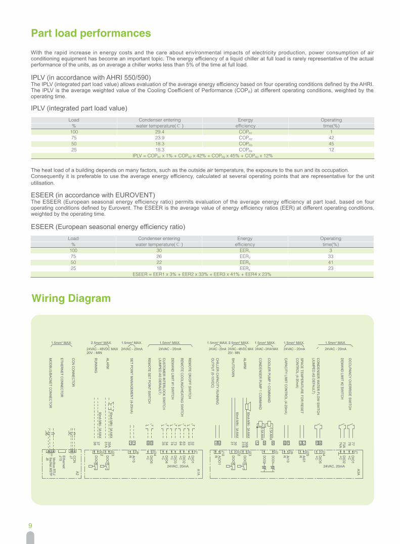
Part load performancesWith the rapid increase in energy costs and the care about environmental impacts of electricity production, power consumption of air conditioning equipment has become an important topic. The energy efficiency of a liquid chiller at full load is rarely representative of the actual performance of the units, as on average a chiller works less than 5% of the time at full load.
IPLV (in accordance with AHRI 550/590)The IPLV (integrated part load value) allows evaluation of the average energy efficiency based on four operating conditions defined by the AHRI. The IPLV is the average weighted value of the Cooling Coefficient of Performance (COPR) at different operating conditions, weighted by the operating time.
Load Condenser entering Energy Operating% water temperature(℃ ) efficiency time(%)
100 29.4 COPR1 175 23.9 COPR2 4250 18.3 COPR3 4525 18.3 COPR4 12
IPLV = COPR1 x 1% + COPR2 x 42% + COPR3 x 45% + COPR4 x 12%
Load Condenser entering Energy Operating% water temperature(℃ ) efficiency time(%)
100 30 EER1 375 26 EER2 3350 22 EER3 4125 18 EER4 23
ESEER = EER1 x 3% + EER2 x 33% + EER3 x 41% + EER4 x 23%
Wiring Diagram
The heat load of a building depends on many factors, such as the outside air temperature, the exposure to the sun and its occupation.Consequently it is preferable to use the average energy efficiency, calculated at several operating points that are representative for the unit utilisation.
ESEER (in accordance with EUROVENT)The ESEER (European seasonal energy efficiency ratio) permits evaluation of the average energy efficiency at part load, based on four operating conditions defined by Eurovent. The ESEER is the average value of energy efficiency ratios (EER) at different operating conditions, weighted by the operating time.
ESEER (European seasonal energy efficiency ratio)
IPLV (integrated part load value)

10
Chiller dimension
Model A B C D E F G H I J K P W S R19PVH**3H**3- 3132 1157 1826 2756 1406 863 621 275 297 250 274 958 1119 DN125 DN12519PVK**3K**3- 3142 1210 1934 2756 1406 868 674 304 318 282 296 1160 1210 DN150 DN15019PVL**3L**3- 3192 1210 2060 2756 1406 893 673 327 388 280 311 1160 1210 DN150 DN150
Water inlet condenser
E
W P
250
3020
1000
22
1
1
1 700
500
689
100
600
AD
F
R
Water inlet cooler
Connection guideSee detail A
S
Water outlet condenser
C HI
JK
GB
R
Water outlet cooler
S
120
Sealing gasketChiller pipe
Victaulic coupling
Coupling pipe(Welded with thecustomer pipe)
Model A B C D E F G H I J K P W S R19PVO**3O**3- 4117 1268 2186 3660 2300 908 725 390 400 340 322 1178 1258 DN200 DN20019PVO**3Q**3- 4136 1291 2239 3660 2300 917 725 390 398 400 318 1178 1258 DN200 DN20019PVO**3T**3- 4176 1322 2295 3660 2300 937 725 390 446 360 363 1178 1258 DN200 DN200
Notes:1. Tolerances on nozzle locations and overall dimensions are ±25mm.2. ①Required clearances for maintenance, ②Recommended space for tube removal(clearance 3020/3290 and 1000 can be either on the right or the left side).3. The water pipe connector is the Victaulic coupling,the Victaulic and the pipe are supplied with the chiller,the pipe length is 120mm.4. Above chiller dimension is based on 3 passes and GB pressure vessel heat exchanger design,for the requirements of 2 passes or ASME pressure vessel etc. design,please contact Carrier
local agencies.
120
Sealing gasket Victaulic coupling
Coupling pipe(Welded with thecustomer pipe)
Chiller pipe
Water inlet condenser
R
Water inlet cooler
Connection guideSee detail A
S
E250
100
600
AD
F
Water outlet condenser
R
Water outlet cooler
S
C
HI
JK
GB
W P
3920
1000
22
1
1 700
500
689

11
Chiller Basement
Model A(mm) B(mm) C(mm) P(mm) Q(mm) R(mm) S(mm)
19PVH**3H**3- 1406 863 3132 958 75 1157 80
19PVK**3K**3- 1406 868 3142 1160 75 1210 25
19PVL**3L**3- 1406 893 3192 1160 75 1210 25
19PVO**3O**3- 2300 908 4117 1178 100 1268 40
19PVO**3Q**3- 2300 917 4136 1178 100 1291 40
19PVO**3T**3- 2300 937 4176 1178 100 1322 40
Filters are required to be installed in water entering side, and water quality analysis periodically implement. Water quality should be maintained within the limits indicated in below table.
Recommendations on heat exchange fluids
Water Characteristics Quality Limitation
NH3 <2 ppm
NH4+ <2 ppm
Cl2 <1 ppm
Cl- < 300 ppm
H2S* <0.05 ppm
SO42- < 70 ppm
CO2† <5 ppm
Fe2+/Fe3+ <0.2 ppm
O2 < 5 ppm
Water Characteristics Quality Limitation
NO3 <100 ppm
Si < 0.1 ppm
Al <0.2 ppm
Mn <0.1 ppm
Hardness 71.2<…<151.3mg/l CaCO3
Resistance >3000ohm.cm
Conductivity 200<…<600µS/cm
Ph 7.5<…<9
Chiller outline dimension,more space needed when buliding chiller base
Electric cabinet side
Section diagram for fixing bolts
300
1
00
350
Square hole 100x100to be reserverd for fixing bolts
+2’+2 4’+
4 +
3 +3’+
BA
C
P
Q
S
R
Notes:1. 4 bolts used to fix chiller, bolt size M20×300.2. User can select 1, 2, 3, 4 or 1', 2', 3', 4' as a group to fix bolts.
12
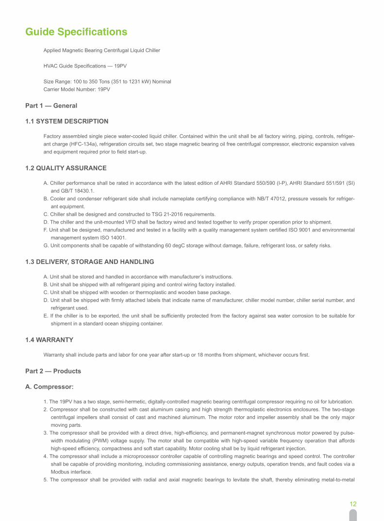
Guide SpecificationsApplied Magnetic Bearing Centrifugal Liquid Chiller
HVAC Guide Specifications — 19PV
Size Range: 100 to 350 Tons (351 to 1231 kW) NominalCarrier Model Number: 19PV
Part 1 — General
1.1 SYSTEM DESCRIPTION
Factory assembled single piece water-cooled liquid chiller. Contained within the unit shall be all factory wiring, piping, controls, refriger-ant charge (HFC-134a), refrigeration circuits set, two stage magnetic bearing oil free centrifugal compressor, electronic expansion valves and equipment required prior to field start-up.
1.2 QUALITY ASSURANCE
A. Chiller performance shall be rated in accordance with the latest edition of AHRI Standard 550/590 (I-P), AHRI Standard 551/591 (SI) and GB/T 18430.1.
B. Cooler and condenser refrigerant side shall include nameplate certifying compliance with NB/T 47012, pressure vessels for refriger-ant equipment.
C. Chiller shall be designed and constructed to TSG 21-2016 requirements. D. The chiller and the unit-mounted VFD shall be factory wired and tested together to verify proper operation prior to shipment. F. Unit shall be designed, manufactured and tested in a facility with a quality management system certified ISO 9001 and environmental
management system ISO 14001. G. Unit components shall be capable of withstanding 60 degC storage without damage, failure, refrigerant loss, or safety risks.
1.3 DELIVERY, STORAGE AND HANDLING
A. Unit shall be stored and handled in accordance with manufacturer’s instructions. B. Unit shall be shipped with all refrigerant piping and control wiring factory installed. C. Unit shall be shipped with wooden or thermoplastic and wooden base package. D. Unit shall be shipped with firmly attached labels that indicate name of manufacturer, chiller model number, chiller serial number, and
refrigerant used. E. If the chiller is to be exported, the unit shall be sufficiently protected from the factory against sea water corrosion to be suitable for
shipment in a standard ocean shipping container.
1.4 WARRANTY
Warranty shall include parts and labor for one year after start-up or 18 months from shipment, whichever occurs first.
Part 2 — Products
A. Compressor:
1. The 19PV has a two stage, semi-hermetic, digitally-controlled magnetic bearing centrifugal compressor requiring no oil for lubrication. 2. Compressor shall be constructed with cast aluminum casing and high strength thermoplastic electronics enclosures. The two-stage
centrifugal impellers shall consist of cast and machined aluminum. The motor rotor and impeller assembly shall be the only major moving parts.
3. The compressor shall be provided with a direct drive, high-efficiency, and permanent-magnet synchronous motor powered by pulse-width modulating (PWM) voltage supply. The motor shall be compatible with high-speed variable frequency operation that affords high-speed efficiency, compactness and soft start capability. Motor cooling shall be by liquid refrigerant injection.
4. The compressor shall include a microprocessor controller capable of controlling magnetic bearings and speed control. The controller shall be capable of providing monitoring, including commissioning assistance, energy outputs, operation trends, and fault codes via a Modbus interface.
5. The compressor shall be provided with radial and axial magnetic bearings to levitate the shaft, thereby eliminating metal-to-metal

13
contact, and thus eliminating friction and the need for oil. The magnetic bearing system shall consist of front, rear, and axial bearings. Both the front and the rear bearings are to levitate the shaft at X and Y directions, and the axial at Z direction. Each bearing position shall be sensed by position sensors to provide real-time repositioning of the rotor shaft, controlled by onboard digital electronics.
6. The compressors shall be serviceable for most of its parts in field. 7. The compressor shall have a Variable Frequency Drive (VFD) for linear capacity modulation, high part-load efficiency and reduced
in-rush starting current. It shall include an Insulated Gate Bipolar Transistor (IGBT) type inverter that converts the DC voltage to an adjustable three-phase AC voltage. Signals from the compressor controller shall determine the inverter output frequency, voltage and phase, thereby regulating the motor speed. In case of power failure, the compressor shall be capable of allowing for a normal de-levitation and shutdown.
8. Compressor speed shall be reduced as condensing temperature and/or heat load reduces, optimizing energy performance through the entire range of capacity. Capacity modulates infinitely as motor speed is varied across the range. Inlet Guide Vanes (IGVs) shall be built-in to further trim the compressor capacity in conjunction with the variable-speed control to optimize compressor performance at low loads.
B. Cooler and Condenser:
1. Unit shall be equipped with a single cooler and condenser. 2. Cooler and condenser shall be manufactured, tested and stamped in accordance with the NB/T 47012 or ASME Pressure vessel code
VIII. 3. The maximum refrigerant-side working pressure will be 1600kPa, and the maximum waterside pressure will be 1000kPa (1600kPa,
2068kPa as options). 4. The cooler and condenser shall be mechanically cleanable, shell-and-tube type with removable heads. Cooler shell shall be insulated
with 19mm (38mm as optional) closed-cell foam and factory fitted. 5. Tubing shall be copper, high-efficiency type, with integral internal and external enhancement unless otherwise noted. Tubes shall be
nominal 19.0mm OD or 25.4mm OD with nominal wall thickness of 0.635mm measured at the root of the fin at the enhanced areas. 6. The cooler and condenser shall have a drain and vent in each head. 7. The cooler and condenser tubesheet shall be aluminum coating on water side for better anti-corrosion effect. 8. Two reseating type pressure relief valves shall be installed on each cooler and condenser. 9. The cooler shall incorporate an active refrigerant level control system to ensure optimum heat transfer performance under all load
conditions. 10. Cooler and condenser shall have water inlet & outlet connection with victaulic couplings to avoid vibrations transmission and accept
small misalignment (water connection kit on demand). 11. Cooler shall be fitted with electronic auto setting water flow switch. Paddle switches or differential pressure switches shall not be ac-
ceptable.
C. Refrigerant Flow Control:
To improve part load efficiency, liquid refrigerant shall be metered from the condenser to the cooler using electronic expansion valve to maintain the proper liquid level of refrigerant in the heat exchangers under both full and part load operating conditions.
D. Controls, Safeties, and Diagnostics:
D.1 Controls:
a. The chiller shall be provided with a factory installed and wired microprocessor control center. The control center shall include a 10.4” colorful touch screen, two basic SIOBs and optional AUX board per system requirements. The microprocessor can be configured for either English or SI units.
b. All chiller and compressor monitoring shall be displayed at the chiller Carrier SmartView® touch screen.
c. The controls shall make use of non-volatile memory.
d. The chiller control system shall have the ability to interface and communicate directly to the building control system. Native BACnet and Modbus protocol are supported.
e. The default standard display screen shall simultaneously indicate the following minimum information:
Guide Specifications

14
Guide Specifications 1) Date and time of day 2) Synoptic screen access button 3) Main Menu access button 4) User Login screen access button 5) Alarm menu access button 6) Setpoint 7) Discharge pressure 8) Sub Cooling pressure 9) Main Suction Pressure 10) Entering chilled water temperature 11) Leaving chilled water temperature 12) Compressor Suction temperature 13) Entering condenser water temperature 14) Leaving condenser water temperature 15) Discharge Gas temperature 16) Sub cooling temperature 17) Compressor Status
f. Schedule Function:The chiller controls shall be configurable for manual or automatic start-up and shutdown. In automatic operation mode, the controls shall be capable of automatically starting and stopping the chiller according to a stored user programmable occupancy schedule. The controls shall include built-in provisions for accepting:1) 365-day occupancy schedules.2) Minimum of 8 separate occupied/unoccupied periods per day.3) Daylight savings start/end.4) 16 user-defined holidays.5) Means of configuring occupancy timed override.6) Chiller start-up and shutdown via remote contact closure.
g. Service Function:The controls shall provide a password protected service function which allows authorized individuals to view an alarm history file which shall contain the last 20 alarm/alert messages with time and date stamp. These messages shall be displayed in text form, not codes.
h. Network Window Function:Each chiller control panel shall be capable of viewing multiple point values and statuses from other like controls connected on a common network, including controller maintenance data. The operator shall be able to alter the remote controller’s set points or time schedule and to force point values or statuses for those points that are operator forcible. The control panel shall also have access to the alarm history file of all like controllers connected on the network.
i. Pump Control:Upon request to start the compressor, the control system shall start the chilled water pump, condenser water pumps and verify that flows have been established.
j. Chilled Water Reset:The control center shall allow reset of the chilled water temperature set point based on any one of the following criteria:1) Chilled water reset based on an external 4 to 20 mA signal.2) Chilled water reset based on a remote temperature sensor (such as outdoor air).3) Chilled water reset based on water temperature rise across the evaporator.
D.2 Safeties:
a. Unit shall automatically shut down when any of the following conditions occur: (Each of these protective limits shall require manual reset and cause an alarm message to be displayed on the control panel screen, informing the operator of the shutdown cause.)
1) Transducer Failure 2) Low evaporator refrigerant temperature 3) Cabinet Thermostat Failure

15
4) High compressor discharge temperature 5) Sub cooling Failure 6) High Superheat Failure 7) Low Superheat Failure 8) High Pressure Switch Failure 9) Loss of cooler water flow 10) Loss of condenser water flow 11) Starter fault
b. Compressor shall automatically shut down when any of the following conditions occur: (Each of these protective limits shall cause an alarm message to be displayed on the control panel screen, informing the operator of the shutdown cause.)
1) Compressor related transducer failure 2) High motor temperature (Inverter, SCR, BMCC, Cavity temperature etc.) 3) Over motor current 4) Low Suction pressure. 5) High Discharge Pressure
c. Internal built-in safeties shall protect the chiller from loss of water flow. Flow switch option is supplied by chiller manufacturer. Differen-tial pressure switches shall not be allowed to be the only form of freeze protection.
D.3 Diagnostics and Service:
A self-diagnostic controls test shall be an integral part of the control system to allow quick identification of malfunctioning components. Once the controls test has been initiated, all pressure and temperature sensors shall be checked to ensure they are within normal op-erating range. A chilled pump test shall energize the chilled water pump, and the control system shall confirm that water flow have been established and require operator confirmation before proceeding. Perform the condenser water pump test in this way, too.
In addition to the automated controls test, the controls shall provide a manual test which permits selection and testing of individual con-trol components and inputs. A thermistor test and transducer test shall display on the Carrier SmartView® touch screen the actual read-ing of each transducer and each thermistor installed on the chiller. All out-of-range sensors shall be identified.
D.4 Multiple Chiller Control:
The chiller controls shall be supplied with two chiller lead/lag system. The control system shall automatically start and stop a lag or sec-ond chiller on a two-chiller system.
E. Electrical
1. Power connection shall be single point to a factory-mounted MCCB. 2. Each compressor equips an EMC/EMI filter which can minimize the harmonics in the high frequency domain (typically above 1 kHz).
It is for IEC61800-3 Category C3 compliance. 3. Each compressor equips a 4% impendence line reactor between the motor drive power circuits and the AC line power. The line reac-
tors provide additional circuit impedance that improves power factor, reduces line current harmonics, and dampens the transient volt-ages on the power line.
F. Start-up:
1. The chiller manufacturer shall provide a factory-trained representative, employed by the chiller manufacturer, to perform the start-up procedures as outlined in the Installation, Operation and Maintenance manual provided by the chiller manufacturer.
2. Manufacturer shall supply the following literature:
a. Installation, operation and maintenance instructions. b. Field wiring diagrams. c. One complete set of pressure vessel assemble-built drawings.
Guide Specifications
16
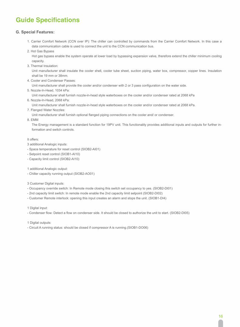
G. Special Features:
1. Carrier Comfort Network (CCN over IP): The chiller can controlled by commands from the Carrier Comfort Network. In this case a data communication cable is used to connect the unit to the CCN communication bus.
2. Hot Gas BypassHot gas bypass enable the system operate at lower load by bypassing expansion valve, therefore extend the chiller minimum cooling capacity.
3. Thermal Insulation:Unit manufacturer shall insulate the cooler shell, cooler tube sheet, suction piping, water box, compressor, copper lines. Insulation shall be 19 mm or 38mm.
4. Cooler and Condenser Passes:Unit manufacturer shall provide the cooler and/or condenser with 2 or 3 pass configuration on the water side.
5. Nozzle-In-Head, 1034 kPa:Unit manufacturer shall furnish nozzle-in-head style waterboxes on the cooler and/or condenser rated at 2068 kPa
6. Nozzle-In-Head, 2068 kPa:Unit manufacturer shall furnish nozzle-in-head style waterboxes on the cooler and/or condenser rated at 2068 kPa.
7. Flanged Water Nozzles:Unit manufacturer shall furnish optional flanged piping connections on the cooler and/ or condenser.
8. EMMThe Energy management is a standard function for 19PV unit. This functionality provides additional inputs and outputs for further in-formation and switch controls.
It offers: 3 additional Analogic inputs: - Space temperature for reset control (SIOB2-AI01) - Setpoint reset control (SIOB1-AI10) - Capacity limit control (SIOB2-AI10)
1 additional Analogic output: - Chiller capacity running output (SIOB2-AO01)
3 Customer Digital inputs: - Occupancy override switch: In Remote mode closing this switch set occupancy to yes. (SIOB2-DI01) - 2nd capacity limit switch: In remote mode enable the 2nd capacity limit setpoint (SIOB2-DI02) - Customer Remote interlock: opening this input creates an alarm and stops the unit. (SIOB1-DI4)
1 Digital input: - Condenser flow: Detect a flow on condenser side. It should be closed to authorize the unit to start. (SIOB2-DI05)
1 Digital outputs: - Circuit A running status: should be closed if compressor A is running.(SIOB1-DO06)
Guide Specifications

The Manufacturer reserves the right to change any produt specifications without prior notices CAT_19PV_E_202101-04
Effective date:
Version:
Supersede:
Jan, 2021
CAT_19PV_E_202008-03