Router Manual
244
Router Manual Version: 2380 Copyright 2007-2010 ImageStream Internet Solutions, Inc., All rights Reserved.
-
Upload
satish-gaikwad -
Category
Documents
-
view
128 -
download
5
Transcript of Router Manual
Router ManualVersion: 2380
Copyright 2007-2010 ImageStream Internet Solutions, Inc., All rights Reserved.

Table of ContentsRouter Manual....................................................................................................................................................1
General Information................................................................................................................................1 Audience...........................................................................................................................................1 Accuracy...........................................................................................................................................1 Warranty...........................................................................................................................................2 Sales and Technical Notes................................................................................................................2 Additional References......................................................................................................................2 FCC Class A Limits.........................................................................................................................4 Canadian Department of Communications Class A Limits.............................................................4 FCC Part 68 Rule Disclosure...........................................................................................................4 Training Courses..............................................................................................................................5 Mailing Lists.....................................................................................................................................5 Document Conventions....................................................................................................................6 Trademarks.......................................................................................................................................6
Introduction and Preparing For Installation............................................................................................6 Introduction......................................................................................................................................6 Unpacking the Router.......................................................................................................................6 Router Software................................................................................................................................7 Pre-Configuration Planning............................................................................................................10 Pre-Installation Information...........................................................................................................10 Basic Configuration Tips................................................................................................................11
How the ImageStream Router Works...................................................................................................12 Summary........................................................................................................................................12 Booting the ImageStream Router...................................................................................................12 ImageStream Router Initialization.................................................................................................13 Router Security and User Management..........................................................................................13 Logging In for the First Time.........................................................................................................14 LAN/WAN Port Status...................................................................................................................14
Configuring Global Setting : The AAA and Global Configuration Menus..........................................15 Setting the Administrative Password.............................................................................................16 Configuring the Router for TACACS+ Server Authentication......................................................17 Disabling Remote AAA Configurations........................................................................................18 Global Configurations....................................................................................................................18 Configuring the User-Configurable Startup Script........................................................................23 Configuring the Default Terminal Type.........................................................................................23 Configuring the Default Text Editor..............................................................................................24 Setting the System Time.................................................................................................................24 Setting the System Time Manually................................................................................................24
Configuring a LAN Interface................................................................................................................25 Understanding the Network Interface Configuration File..............................................................26 Default LAN Interface Configuration............................................................................................27 Customizing the Configuration......................................................................................................27
Advanced Ethernet Configuration........................................................................................................33 Configuring the Virtual Router Redundancy Protocol (VRRP).....................................................33 How Does ImageStream Implement VRRP?.................................................................................34 How to Configure VRRP...............................................................................................................34 Configuring Virtual LAN (VLANS)..............................................................................................36
Configuring a Synchronous Serial WAN Interface..............................................................................37 WAN Port Uses..............................................................................................................................37
i
Table of ContentsRouter Manual
Understanding the Network Interface Configuration File..............................................................39 Configuring a Synchronous Serial WAN Interfacee......................................................................39 Default Serial WAN Interface Configuration................................................................................40 Customizing the Configuration......................................................................................................40
Configuring an Integrated CSU/DSU WAN Interface.........................................................................44 WAN Port Uses..............................................................................................................................45 Understanding the Network Interface Configuration File..............................................................45 Configuring an Integrated CSU/DSU WAN Interface...................................................................45 Default Integrated CSU/DSU WAN Card Configuration..............................................................46 Customizing the Configuration......................................................................................................46 Scaling the connection speed calculation.......................................................................................48 Setting Integrated T1 CSU/DSU Parameters.................................................................................49 Setting Integrated E1 CSU/DSU Parameters.................................................................................52 Setting Integrated DS3/E3 CSU/DSU Parameters.........................................................................55 Configuring Other Serial Interface Parameters..............................................................................56
Configuring an ATM Interface.............................................................................................................58 WAN Port Uses..............................................................................................................................58 Understanding the Network Interface Configuration File..............................................................58 Configuring an ATM Master Interface..........................................................................................58 Default ATM WAN Card Configuration.......................................................................................59 Customizing the Configuration......................................................................................................59 Setting ATM DS3/E3 Master Interface Parameters.......................................................................62 Setting ATM OC-3/OC-12 Master Interface Parameters...............................................................65 Configuring an ATM Subinterface.................................................................................................66
Configuring a Frame-Relay Interface...................................................................................................69 WAN Port Uses..............................................................................................................................69 Understanding the Network Interface Configuration File..............................................................69 Configuring a Frame Relay Master Interface.................................................................................69 Default Frame Relay Interface Configuration................................................................................70 Customizing the Configuration......................................................................................................70 Setting Frame Relay Master Interface Parameters.........................................................................73 Configuring a Frame Relay Subinterface.......................................................................................74 Enabling FRF.12 end-to-end fragmentation on a subinterface......................................................76
Configuring an ISDN BRI Interface.....................................................................................................78 WAN Port Uses..............................................................................................................................78 Understanding the Network Interface Configuration File..............................................................78 Configuring an ISDN BRI Interface..............................................................................................78 Default ISDN BRI Interface Configuration...................................................................................79 Customizing the Configuration......................................................................................................79 Configuring ISDN BRI Switch Settings........................................................................................82 Configuring ISDN BRI Interface Characteristics..........................................................................83 Configuring ISDN BRI for Dial-On-Demand and Dial-Backup....................................................85
Configuring an ADSL Interface............................................................................................................88 Advanced Configuration Examples......................................................................................................88
Virtual router example emulating four ADSL routers using PPPoA and Ethernet VLANs..........88 Troubleshooting..............................................................................................................................91
Configuring DHCP Services.................................................................................................................93 Introduction....................................................................................................................................93
ii
Table of ContentsRouter Manual
Configuring an Interface as a DHCP Client...................................................................................94 Configuring DHCP Relay Services................................................................................................94 Configuring the Router as a DHCP Server....................................................................................97 Troubleshooting..............................................................................................................................98
Configuring Bonder for Load Balancing and Aggregation..................................................................99 Configuring Load Balancing and Aggregation Using Bonder.....................................................100 Valid Interfaces for the Bond Command.....................................................................................101
Configuring Multilink PPP for Load Balancing and Aggregation.....................................................102 Introduction..................................................................................................................................102 Configuring Load Balancing and Aggregation using Multilink PPP...........................................103 Valid Interfaces for the Multilink device.....................................................................................105
Configuring Multilink Frame for Load Balancing and Aggregation..................................................105 Configuring Bridging..........................................................................................................................105 Configuring IP Tunnels......................................................................................................................106
Understanding Tunnel Devices....................................................................................................107 Configuring a Simple SSL Tunnel using OPENVPN..................................................................107 Configuring a Dynamically Addressed SSL Tunnel using OPENVPN.......................................110 Configuring CIPE (Crypto IP Encapsulation) Tunnels................................................................111 Configuring GRE Tunnels............................................................................................................114
Configuring L2TP for LNS.................................................................................................................116 Configuring L2TP for LAC................................................................................................................117
Client configuration......................................................................................................................117 Server configuration.....................................................................................................................118 Troubleshooting............................................................................................................................118
Configuring OSPF..............................................................................................................................119 Overview.............................................................................................................................................120 Tools...................................................................................................................................................120 Examples.............................................................................................................................................120 Documentation and Futher reading.....................................................................................................120 Configuring BGP................................................................................................................................120 Overview.............................................................................................................................................120 Examples.............................................................................................................................................120 Documentation and Futher reading.....................................................................................................120 Configuring Rate Limiting Within SAND..........................................................................................121
Understanding and Configuring Rate Limiting using Rate-Limit................................................122 Valid Interfaces for the Rate-Limit Command.............................................................................123
Configuring Services: Quality of Service Menu.................................................................................123 Quality of Service Menu..............................................................................................................123 Configuring Quality of Service using Service, Policy and Interface definitions.........................125 Configuring Quality of Service using BWINIT/BWADD Filter Method....................................128 Initializing an Interface using BWINIT.......................................................................................129 Adding Limits to Initialized Devices using BWADD..................................................................130 Grouping Hosts and Networks.....................................................................................................131 Configuring Quality of Service using BWINIT/BWADD Classify Method...............................131 Classifying Traffic using iptables CLASSIFY.............................................................................134 Configuring Quality of Service using Differentiated Services (DIFFSERV)..............................136 Enabling QoS at Boot-time..........................................................................................................137 Disabling QoS at Boot-time.........................................................................................................137
iii
Table of ContentsRouter Manual
Instating QoS Rules......................................................................................................................137 Clearing QoS Rules......................................................................................................................138 Restoring Factory Default QoS Configuration.............................................................................138 Returning to the Firewall/QOS Configuration Menu...................................................................138
Configuring Services: Dialout PPP Menu..........................................................................................139 Enabling Dialout PPP at Boot-time..............................................................................................141 Disabling Dialout PPP at Boot-time.............................................................................................141 Start Dialout PPP..........................................................................................................................141 Stop Dialout PPP..........................................................................................................................142 Viewing Dialer Messages.............................................................................................................142 Returning to the Service Configuration Menu.............................................................................142
Configuring Services: Firewall Menu.................................................................................................143 Configuring Firewalls and Packet Filtering using IPTABLES....................................................144 Enabling firewall Rules at Boot-time...........................................................................................145 Disabling Firewall Rules at Boot-time.........................................................................................145 Instating Firewall Rules................................................................................................................146 Clearing Firewall Rules................................................................................................................146 Restoring the Factory Default Firewall Configuration.................................................................146 Returning to the Firewall and QOS Menu....................................................................................147
Configuring Services: IPSec VPN Menu............................................................................................147 IPSEC VPN Pre-Configuration Information................................................................................149 Using the Built-in Automated Script to Configure a VPN Tunnel..............................................150 Auto Configuring a VPN Tunnel on a Remote ImageStream Router..........................................152 Selecting manual configuration for a VPN tunnel.......................................................................154 Managing the IPSec Service.........................................................................................................155 Enabling IPSec at Boot-time........................................................................................................155 Disabling IPSec at Boot-time.......................................................................................................155 Starting the IPSec Service............................................................................................................156 Stopping the IPSec Service..........................................................................................................156 Returning to the Service Configuration Menu.............................................................................156
Configuring Services: Network Interfaces Menu...............................................................................157 Configuring Services: Serial Console (SCONSOLE) Menu..............................................................157
Configuring the Serial Console for Use with a Terminal or Terminal Program..........................158 Configuring the Serial Console for Use with a Modem...............................................................159 Enabling the Serial Console at Boot-time....................................................................................160 Disabling the Serial Console at Boot-time...................................................................................160 Starting the Serial Console Service..............................................................................................160 Stopping the Serial Console Service............................................................................................161 Returning to the Service Configuration Menu.............................................................................161
Configuring Services: SNMP Menu...................................................................................................161 SNMP Menu.................................................................................................................................161 Configuring the SNMP Service....................................................................................................163 Configuring the SNMP Community String..................................................................................163 Enabling Trap Generation............................................................................................................164 Enabling SNMP at Boot-time.......................................................................................................165 Disabling SNMP at Boot-time.....................................................................................................166 Starting the SNMP Service...........................................................................................................166 Stopping the SNMP Service.........................................................................................................166
iv
Table of ContentsRouter Manual
Returning to the Service Configuration Menu.............................................................................167 SNMP Configuration and Usage Examples.................................................................................167 SNMP MIBs.................................................................................................................................167 Basic MIB2 MIBs........................................................................................................................167 ImageStream MIBs.......................................................................................................................167
Configuring Service: SSH Menu........................................................................................................167 Configuring the SSH Service.......................................................................................................169 Enabling SSH at Boot-time..........................................................................................................171 Disabling SSH at Boot-time.........................................................................................................171 Starting the SSH Service..............................................................................................................171 Stopping the SSH Service............................................................................................................172 Returning to the Service Configuration Menu.............................................................................172 Disabling the Telnet Service........................................................................................................172
Configuring_CALEA_Intercepts........................................................................................................173 Detailed command syntax:...........................................................................................................173 Complete 2 client example:..........................................................................................................174
Backup/Restore Menu: Managing Configurations.............................................................................176 Introduction..................................................................................................................................176 Using the Backup Menu...............................................................................................................177 Backing Up Configurations to a Floppy Disk..............................................................................177 Backing Up Configurations to a Remote Machine using FTP.....................................................178 Backing Up Configurations to a Remote Machine using SCP.....................................................178 Backing Up Configurations to the Flash Device..........................................................................179 Backing Up Configurations to a File............................................................................................179 Backing Up Configurations through a Terminal Program using ZMODEM...............................180 Returning to the Backup/Restore Menu.......................................................................................181 Using the Restore Menu...............................................................................................................181 Returning to the Backup/Restore Menu.......................................................................................185
Using the Interface Statistics (STATS) Program................................................................................186 Understanding the Summary Screen............................................................................................186 Understanding the Detail Screen for Ethernet Devices................................................................188 Understanding the Detail Screen for Other Devices....................................................................191 Understanding the CSU/DSU Detail Screen for Other Devices..................................................193 Viewing Traffic............................................................................................................................195 Returning to the Main Menu........................................................................................................196
Add-on Packages................................................................................................................................196 Overview.............................................................................................................................................196 Setup...................................................................................................................................................196 Available add-on Packages.................................................................................................................197 Troubleshooting..................................................................................................................................197
Introduction..................................................................................................................................197 Troubleshooting with the Interface Statistics Detail Screen........................................................197 Serial Lines: Line Status Conditions............................................................................................197 Serial Lines: Increasing Output Drops on Serial Link.................................................................200 Serial Lines: Increasing Input Fifo Buffer Drops on Serial Link.................................................201 Serial Lines: Increasing Non-Fifo Input Drops on Serial Link....................................................202 SERIAL LINES: INPUT ERRORS OF OVER 1% OF TOTAL INTERFACE TRAFFIC........203 Serial Lines: Troubleshooting Serial Line Input Errors...............................................................204
v
Table of ContentsRouter Manual
Serial Lines: Increasing Carrier Transition Count on Serial Link................................................206 Troubleshooting Clocking Problems............................................................................................207 Troubleshooting T1/E1 CSU/DSU Problems...............................................................................210 Troubleshooting Ethernet Problems.............................................................................................213 Troubleshooting Service Specific Problems................................................................................214 Failsafe Mode...............................................................................................................................216 Troubleshooting Questions - Getting Technical Support.............................................................217 Contact Information.....................................................................................................................217
Router Memory Requirements............................................................................................................218 4.2 Distributions...........................................................................................................................218 4.4 Distributions...........................................................................................................................218
RADIUS Supported Attributes...........................................................................................................218 Authentication requests accept the following attributes:.............................................................218 Authentication requests send the folowing attributes:.................................................................218 Accounting requests send the following attributes:.....................................................................218
Supported RFCs..................................................................................................................................219 Product Return Procedures.................................................................................................................219
Factory Repair..............................................................................................................................219 Re-packing Guidelines For Equipment Return............................................................................220 Specific Packing Guidelines.........................................................................................................220
Helpful Tools......................................................................................................................................220 Netmask Conversion Table..........................................................................................................221 RJ48 Loopback Plug for testing DDS, T1 and E1 CSU/DSU's...................................................221 T1 Line Basics..............................................................................................................................222 Packet flow inside the Linux Kernel............................................................................................223
Basic Networking................................................................................................................................223 Introduction..................................................................................................................................223 Domain Name Server (DNS).......................................................................................................224 Network Addressing.....................................................................................................................224 IP Addressing...............................................................................................................................224 IP Address Classes.......................................................................................................................224 Reserved IP Addresses.................................................................................................................226 Private IP Networks......................................................................................................................226 Netmasks......................................................................................................................................227 Understanding the Network Interface Configuration File (wan.conf).........................................228 Understanding WAN's..................................................................................................................229
Glossary..............................................................................................................................................231
vi
Router Manual
General Information
ImageStream Internet Solutions, Inc.
7900 East 8th Road Plymouth, Indiana 46563 USA
800.813.5123574.935.8484
The information contained in this manual is proprietary in nature, and may not be duplicated, in wholeor in part, for any purpose, without prior written consent of ImageStream. Receipt of this manual isconsidered acceptance of these conditions.
Audience
This guide is designed for qualified system administrators, network managers, and persons with aworking knowledge of networking and routing. The examples in this manual assume the use of thePico text editor. Appendix A, "Networking Concepts," only provides an overview of network addressconventions, and should not be used as a substitute for careful study of these principles. Refer to"Additional References" in this preface for appropriate Requests for Comments (RFC's) and othersuggested reading.
Accuracy
All information presented in this manual is based on the latest product information available at thetime of printing. ImageStream has carefully reviewed the accuracy of this manual, but cannot be heldliable for omissions or errors that may appear. ImageStream reserves the right to revise thispublication and to make changes in its contents without obligation of notifying any persons of suchrevision changes.
Router Manual 1
Warranty
ImageStream Internet Solutions, Inc. warrants that at the time of shipment the router product and itsinstalled components shall be free from defect in material and workmanship. ImageStream InternetSolutions, Inc. warrants that the router will meet the product's standard specifications at the time ofshipment. This warranty excludes damage resulting from mishandling, tampering, improperinstallation and misuse by the purchaser.
ImageStream Internet Solutions, Inc. warrants the router for a period of 1 year from the invoice date.For warranty claims, contact your place of purchase, or ImageStream Internet Solutions, Inc.immediately upon the discovery of such defect. If the Router or its installed components are found tobe defective, ImageStream Internet Solutions, Inc. will repair or replace the router at ImageStream'sdiscretion. To view ImageStream's Limited Warranty and Software License please visithttp://www.imagestream.com/Revolution/LegalText.html
In no event shall ImageStream Internet Solutions, Inc., be liable for direct, indirect, incidental orconsequential damages in connection with, or arising from, the furnishing, performance, or use of therouter. Purchaser may have other rights that vary from state to state.
Sales and Technical Notes
ImageStream's on-line resources provide the latest information on software driver upgrades,frequently asked questions and other issues. These services are available 24 hours a day, 7 days aweek via the World Wide Web at http://support.imagestream.com.
The ImageStream Support Team is available 24 hours a day, 7 days a week. For phone support pleasecall 574.935.8484. The ImageStream fax number is 574.935.8488. For email support please send mailto [email protected].
Additional References
Consult the following RFC's and books for more information about the topics covered in this manual.
RFC's
To find an RFC online, visit the website of the Internet Engineering Task Force (IETF) athttp://www.ietf.org/.RFC 768, User Datagram ProtocolRFC 791, Internet ProtocolRFC 792, Internet Control Message ProtocolRFC 793, Transmission Control ProtocolRFC 854, Telnet Protocol SpecificationRFC 950, Internet Standard Subnetting Procedure RFC 1058, Routing Information ProtocolRFC 1112, Host Extensions for IP MulticastingRFC 1144, Compressing TCP/IP Headers for Low-Speed Serial Links RFC 1157, A Simple NetworkManagement Protocol (SNMP)RFC 1166, Internet NumbersRFC 1212, Concise MIB Definitions
Router Manual
2 Warranty
RFC 1213, Management Information Base for Network Management of TCP/IP-based Internets:MIB-IIRFC 1256, ICMP Router Discovery Messages RFC 1321, The MD5 Message-Digest AlgorithmRFC 1331, The Point-to-Point Protocol (PPP) for the Transmission of Multiprotocol Datagrams overPoint-to-Point LinksRFC 1332, The PPP Internet Protocol Control Protocol (IPCP) RFC 1334, PPP AuthenticationProtocolsRFC 1349, Type of Service in the Internet Protocol SuiteRFC 1413, Identification ProtocolRFC 1483, Multiprotocol Encapsulation over ATM Adaption Layer 5RFC 1490, Multiprotocol Interconnect Over Frame RelayRFC 1542, Clarifications and Extensions for the Bootstrap ProtocolRFC 1552, The PPP Internet Packet Exchange Control Protocol (IPXCP)RFC 1587, The OSPF NSSA OptionRFC 1597, Address Allocations for Private InternetsRFC 1627, Network 10 Considered Harmful (Some Practices Shouldn't be Codified)RFC 1634, Novell IPX Over Various WAN Media (IPXWAN)RFC 1661, The Point-to-Point Protocol (PPP)RFC 1700, Assigned NumbersRFC 1723, RIP Version 2RFC 1771, A Border Gateway Protocol 4 (BGP-4)RFC 1812, Requirements for IP Version 4 RoutersRFC 1814, Unique Addresses are GoodRFC 1818, Best Current PracticesRFC 1824, Requirements for IP Version 4 RoutersRFC 1825, Security Architecture for the Internet ProtocolRFC 1826, IP Authentication HeaderRFC 1827, IP Encapsulating PayloadRFC 1828, IP Authentication Using Keyed MD5RFC 1829, The ESP DES-CBC TransformRFC 1851, The ESP Triple DES TransformRFC 1877, PPP IPCP Extensions for Name Server AddressesRFC 1878, Variable Length Subnet Table for IPv4RFC 1918, Address Allocation for Private InternetsRFC 1962, The PPP Compression Control Protocol (CCP)RFC 1965, Autonomous System Confederations for BGPRFC 1966, BGP Route Reflection, An Alternative to Full Mesh IBGPRFC 1974, PPP Stac LZS Compression ProtocolRFC 1990, The PPP Multilink Protocol (MP)RFC 1994, PPP Challenge Handshake Authentication Protocol (CHAP)RFC 1997, BGP Communities AttributeRFC 2003, IP Encapsulation within IPRFC 2104, HMAC: Keyed-Hashing for Message AuthenticationRFC 2125, The PPP Bandwidth Allocation Protocol (BAP), The PPP Bandwidth Allocation ControlProtocol (BACP)RFC 2131, Dynamic Host Configuration ProtocolRFC 2132, DHCP Options and BOOTP Vendor ExtensionsRFC 2138, Remote Authentication Dial In User Service (RADIUS) RFC 2139, RADIUS Accounting
Router Manual
Additional References 3

RFC 2153, PPP Vendor ExtensionsRFC 2328, OSPF Version 2RFC 2364, PPP over AAL5RFC 2400, Internet Official Protocol StandardsRFC 2403, The Use of HMAC-MD5-96 within ESP and AHRFC 2404, The Use of HMAC-SHA-1-96 within ESP and AHRFC 2405, The ESP DES-CBC Cipher Algorithm with Explicit IV RFC 2451, The ESP CBC-ModeCipher AlgorithmRFC 2453, RIP Version 2RFC 2663, IP Network Address Translator (NAT) Terminology and Considerations
FCC Class A Limits
Warning: Changes or modifications to this unit not expressly approved by the party responsible forcompliance could void the user's authority to operate the equipment.
Note: This equipment has been tested and found to comply with the limits for a Class A digital devicepursuant to Part 15 of the FCC Rules. These limits are designed to provide reasonable protectionagainst harmful interference when the equipment is operated in a commercial environment. Thisequipment generates, uses, and can radiate radio frequency energy and, if not installed and used inaccordance with the instruction manual, may cause harmful interference to radio communications.Operation of the equipment in a residential area is likely to cause harmful interference in which casethe user will be required to correct the interference at his own expense.
Shielded cables must be used with this unit to ensure compliance with FCC Class A limits.
Canadian Department of Communications Class A Limits
This digital apparatus does not exceed the Class A limits for radio noise emissions from digitalapparatus set out in the Radio Interference Regulations of the Canadian Department ofCommunications.
Le present appareil numerique n'emet pas de bruits radioelectriques depassant les limites applicablesaux appareils numeriqqes de la class A prescrites dans le Reglement sur le brouillage radioelectriqueedicte par le ministere des Communications du Canada.
FCC Part 68 Rule Disclosure
The following information is required by FCC Part 68 Rules which informs the user of his/her rightsand obligations in connecting this equipment to the network and in ordering service. This equipmentcomplies with Part 68 of FCC Rules. Please note the following:
1. When you order T1 service in North America, the telephone company will need to know thefollowing:
a. The Facility Interface Code:
04DU-B (1.544 MB D4 framing format)◊
Router Manual
4 FCC Class A Limits

04DU9-C (1.544 MB ESF framing format)◊ b. The Service Order Code:
6.0F◊
Note: A signal power affidavit may be required to guarantee encoded analog contentand billing protection unless this unit is used in combination with an XD type deviceor no encoded analog signals and billing information will be transmitted.
c. The USOC Jack Required:
RJ48C◊ In addition, if requested, please inform the telephone company the make, model andFCC Registration Number, which can be found on the label.
2. Your telephone company may make changes to its facilities, equipment, operations or proceduresthat could affect the proper functioning of your equipment. If they do, you will be notified in advanceto give you and opportunity to maintain uninterrupted telephone service.
3. If your telephone equipment causes harm to the telephone network, the telephone company maydiscontinue your service temporarily. If possible, they will notify you in advance, but if advancenotice is not practical, you will be notified as soon as possible. You will be informed of your right tofile a complaint with the FCC.
4. If you experience trouble with telephone equipment, please contact us for information on obtainingservice or repairs. Only ImageStream or our authorized agents should perform repairs.
5. You are required to notify the telephone company when this unit is disconnected from the network.
Training Courses
ImageStream offers hands-on, technical training courses on ImageStream products and theirapplications. For more information, visit the ImageStream Web site athttp://www.imagestream.com/Training.html.
Mailing Lists
ImageStream maintains the following Internet mailing lists for ImageStream router users:
isis-announce - a general announcements list that carries announcements from ImageStreamregarding product releases, news releases and general company information. To subscribe,send email to [email protected] with subscribe isis-announce in the body of themessage.
◊
isis-support - a general discussion list that carries announcements from the isis-announce list,as well as software version release announcements and product releases. To subscribe, sendemail to [email protected] with subscribe isis-support in the body of themessage.
◊
Router Manual
FCC Part 68 Rule Disclosure 5
Document Conventions
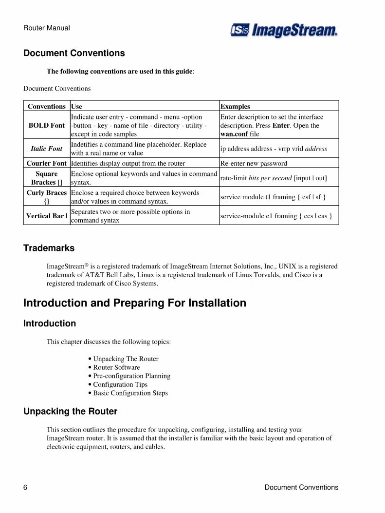
The following conventions are used in this guide:
Document Conventions
Conventions Use Examples
BOLD FontIndicate user entry - command - menu -option-button - key - name of file - directory - utility -except in code samples
Enter description to set the interfacedescription. Press Enter. Open thewan.conf file
Italic Font Indetifies a command line placeholder. Replacewith a real name or value ip address address - vrrp vrid address
Courier Font Identifies display output from the router Re-enter new passwordSquare
Brackes []Enclose optional keywords and values in commandsyntax. rate-limit bits per second [input | out]
Curly Braces{}
Enclose a required choice between keywordsand/or values in command syntax. service module t1 framing { esf | sf }
Vertical Bar | Separates two or more possible options incommand syntax service-module e1 framing { ccs | cas }
Trademarks
ImageStream® is a registered trademark of ImageStream Internet Solutions, Inc., UNIX is a registeredtrademark of AT&T Bell Labs, Linux is a registered trademark of Linus Torvalds, and Cisco is aregistered trademark of Cisco Systems.
Introduction and Preparing For Installation
Introduction
This chapter discusses the following topics:
Unpacking The Router• Router Software• Pre-configuration Planning• Configuration Tips• Basic Configuration Steps•
Unpacking the Router
This section outlines the procedure for unpacking, configuring, installing and testing yourImageStream router. It is assumed that the installer is familiar with the basic layout and operation ofelectronic equipment, routers, and cables.
Router Manual
6 Document Conventions

Though an ImageStream router is shipped in a sturdy cardboard box with foam padding, it may stillbe damaged in shipping. We suggest that each box and its contents be examined for visual damage. Ifyour shipment arrives damaged, incomplete, or incorrect, contact ImageStream Internet Solutions,Inc. immediately.
The following items are typically shipped in a router box. However, the packing list should bereviewed to verify the completeness of the shipment:
Base router chassis
Router chassis• Power cable(s)• Quick start guide• Terms and Conditions of Sale and Warranty Notice•
Cards without integrated CSU/DSUs
WAN card with RS232, EIA-530 or V.35 interface options• RS232, RS449, EIA530 or V.35 Adapter Cable (if ordered)•
Cards with integrated CSU/DSUs
WAN card with CSU and RS232, EIA-530 or V.35 interface options(if any)
•
RS232, RS449, EIA530 or V.35 Adapter Cable (if ordered)• RJ48 Loop Back Plug (if ordered)•
The Ethernet (100BaseTX/10BaseT), Token Ring, serial and console ports contain safety extra-lowvoltage (SELV) circuits. T1, 56 Kbps (DDS), BRI and PRI circuits are telephone-network voltage(TNV) circuits. Avoid connecting SELV circuits to TNV circuit equipment, such as WAN cards withintegrated CSU/DSUs, as this can cause damage to the equipment.
Router Software
All ImageStream routers are shipped with the ImageStream Linux router software distribution. Thiswiki contains detailed information on the configuration and application of the software. ImageStreamLinux contains the following standard embedded packages:
Base-binaries - Includes all basic Linux binary utilities and devices. This package includescommand line utilities such as vi, pico and rm as well as the tty login devices and process IDstorage directories.
Base-libraries - Includes all shared libraries required by Enterprise Linux. This packageincludes curses libraries, terminal information and basic cryptography libraries.
Base-networking - Includes all basic Linux networking utilities and libraries. This packageincludes command line utilities such as iptables, telnet, and ping and their associated libraries.
Router Manual
Unpacking the Router 7
Failsafe-Configuration - This package and associated directory contains basic informationrequired to boot the router. Basic entries in the /etc configuration directory and startup scriptsare included in the package. Coupled with the Failsafe directory stored in the router'snonvolatile (Flash) RAM, this package can be used to boot the router with a simple defaultconfiguration in the event of problems with the main configuration or if the router passwordis lost.
OpenSSH - This package contains the command line utilities and libraries for the opensource secure shell (SSH) program. This package is used to support secure connections to therouter over a network connection.
OpenSSL - This package contains the libraries for the open source secure socket layer (SSL)libraries. This package is used to support SSH, SNMP, SSL (OpenVPN) VPNs and othersecure connections to the router over a network connection.
Pluggable-Auth-Module - This package contains the libraries for open source PAMsoftware. This package supports login authentication over various methods, includingTACACS+, RADIUS, and UNIX password files through a single authentication mechanism.
QOS-routing - This package contains the command line utilities for quality of service andbandwidth shaping management. Additionally, the default QoS and bandwidth shapingconfiguration files are stored in this package.
VRRP - This package contains VRRPd, ImageStream's open source implementation of theVirtual Router Redundancy Protocol as specified in rfc2338. VRRPd is interoperable withother RFC-based VRRP implementations, including Cisco and Juniper, and is included as astandard feature on ImageStream routers.
adsl - This package contains software to support ImageStream's ADSL, ADSL2, andADSL2+ interfaces used in conjunction with ImageStream routers.
bridge - This package enables Enterprise Linux's bridging support for WAN, LAN, Tunneland other standard devices.
crond - This package contains the cron scheduler daemon. cron enables users to scheduleevents on the router, and supports the router's network time protocol (NTP) synchronization.
dialout-ppp - This package contains support for ImageStream's analog modems used foroutbound connectivity.
ebtables - This package contains the command line utilities and libraries that support theLinux ebtables software for filtering and access control on bridged (layer 2) network devices.
gated - This package contains ImageStream's version of NextHop Technologies GateD. Thisprogram is used to support dynamic routing protocols such as BGP, OSPF, ISIS and RIP.
IPSec-OpenSWan - This package contains the open source IPSec cryptography andencryption service, OpenSWan. This set of utilities and libraries support IPSec VPN's with
Router Manual
8 Router Software
high encryption.
iptables - This package contains the command line utilities and libraries that support theLinux iptables software for filtering and access control on routed (layer 3) network devices.
isdn - This package contains support for ImageStream's ISDN terminal adapters used foroutbound connectivity.
kernel-modules - This package contains Linux kernel modules for the Enterprise Linuxkernel used with the distribution version on the router. Special IP routing and policy routingmodules, as well as Ethernet chipset and hardware health monitoring modules are included inthis package.
Net-SNMP - This package contains the SNMP management package for the router. Allcommand line utilities and supported MIB's are contained in this package.
nprobe - This package contains the command line utilities, libraries and scripts required tosupport the embedded NetFlow probe included with ImageStream routers.
pppd - This package contains the command line utilities, libraries and scripts required tosupport PPP authentication and encapsulation over Ethernet, ATM and other devicescommonly used with broadband aggregation.
router-utils - This package contains Enterprise Linux's menuing system and otherrouter-specific utilities. All of the utilities required to start and stop various router services areincluded in this package.
SAND - This package contains ImageStream's Inetics™ driver component system forImageStream routers. Inetics provides the framework and support for all WAN cards used inconjunction with ImageStream routers.
sconsole - This package contains the programs and libraries required to provide a serialconsole connection to the router and support for both modem and dumb terminal/direct serialcable connections to the router.
sensors - This package contains the utilities and libraries for hardware health monitoring. Thesensors package supports monitoring of CPU temperatures, CPU fans and speeds, chassis fansand speeds and other hardware monitors supported by ImageStream router hardware.
cipe - This package contains the software that supports the Crypto IP Encapsulation (CIPE)VPN protocol available on ImageStream routers and standard Linux systems.
OpenVPN - This package contains the software that supports the SSL VPN protocolavailable on ImageStream routers and supported by most common operating systems.
Quagga - This package contains the open source Quagga routing daemons. These programsare used to support dynamic routing protocols such as BGP, OSPF and RIP. This unsupportedpackage is provided for administrators familiar with Quagga, Zebra or Cisco-like command
Router Manual
Router Software 9
line interfaces.
udhcpd - This package contains the embedded DHCP client, DHCP server and DHCP relayclient included with Enterprise Linux.
Pre-Configuration Planning
Before the ImageStream router can be used to connect wide area networks (WANs), you must installthe hardware using the instructions in the installation guide for your system. This configuration guideis designed to introduce the most common configuration options available for ImageStream products.Review this material before you configure your router and, if possible, answer the followingquestions:
What general configuration do you want to implement?◊ Will you be using internal or external CSU/DSU's with your high-speedlines?
◊
Will your high-speed lines use ATM, Frame Relay, HDLC, PPP or ISDNencapsulation?
◊
Do you need dial-on-demand for ISDN backup connections?◊ Do you need to bond multiple circuits or virtual circuits together?◊ Do you want packet filtering or firewalling for Internet or other connections?◊ Have you obtained a sufficient number of network addresses, or do you wantto use the network address translation (NAT) software?
◊
Do you need to bridge multiple segments together?◊ Do you want to enable Simple Network Management Protocol (SNMP) fornetwork monitoring?
◊
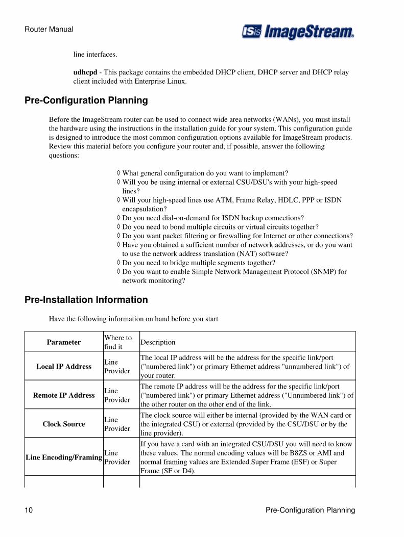
Pre-Installation Information
Have the following information on hand before you start
Parameter Where tofind it Description
Local IP Address LineProvider
The local IP address will be the address for the specific link/port("numbered link") or primary Ethernet address "unnumbered link") ofyour router.
Remote IP Address LineProvider
The remote IP address will be the address for the specific link/port("numbered link") or primary Ethernet address ("Unnumbered link") ofthe other router on the other end of the link.
Clock Source LineProvider
The clock source will either be internal (provided by the WAN card orthe integrated CSU) or external (provided by the CSU/DSU or by theline provider).
Line Encoding/Framing LineProvider
If you have a card with an integrated CSU/DSU you will need to knowthese values. The normal encoding values will be B8ZS or AMI andnormal framing values are Extended Super Frame (ESF) or SuperFrame (SF or D4).
Router Manual
10 Pre-Configuration Planning

DLCI Number (FrameRelay Only)
LineProvider
Used to establish virutal circuits across frame relay nertworks toremote router.
Basic Configuration Tips
The exact configuration steps you follow depend upon the hardware you are installing and yournetwork configuration. However, the following general configuration steps are the same for allImageStream products:
1. Install the ImageStream hardware as described in the Quick Start Guide shipped with yourrouter. Additional information on configuring the router password, IP address and other basicinformation is below.
2. Boot the system and log in with the administrative password. You can configure theImageStream router from a keyboard and monitor (on supported systems), a terminal attachedto the console port, by an administrative telnet or ssh session, or by a network connection.
3. Configure the global settings. Global settings are described in Chapter 4, "ConfiguringGlobal Settings: the AAA and Global Configuration Menus."
4. Configure the Ethernet or Token Ring settings. Ethernet and Token Ring settings aredescribed in Chapter 5, "Configuring a LAN Interface."
5. Configure the synchronous serial WAN port(s), if available. Synchronous serial WANinterface settings are described in Chapter 7, "Configuring a Synchronous WAN Interface."
6. Configure the integrated CSU/DSU connection(s), if available. OC-12, OC-3, ATM DS3,ATM E3, T1, and E1 connection configuration is described in Chapter 8, "Configuring anIntegrated CSU/DSU WAN Interface." ISDN BRI connection configuration is covered inChapter 11, "Configuring an ISDN BRI Interface."
7. Configure the ATM connection(s), if available. ATM OC-12, OC-3, DS3, E3, T1, and E1connection configuration is described in Chapter 9, "Configuring an ATM Interface."
8. Configure the Frame Relay connection(s), if available. Frame Relay DS3, E3, T1, and E1connection configuration is described in Chapter 10, "Configuring a Frame Relay Interface."
9. Configure ISDN BRI connection(s), if available. Basic Rate ISDN connectionconfiguration is described in Chapter 11, "Configuring an ISDN BRI Interface."
10. Configure iptables, if you are using it. iptables is Linux's open source traffic filtering andfirewalling mechanism for networks. iptables configuration is described in Chapter 20,"Configuring Services: Firewall Menu."
11. Configure Differentiated Services/Quality of Service, if you are using it. ImageStreamuses the IETF-standard DiffServ implementation for bandwidth/rate limiting and quality ofservice for networks. Configuration of these tools is described in Chapter 13, "Configuring
Router Manual
Pre-Installation Information 11
Bonder For Load Balancing And Aggregation," Chapter 17, "Configuring Rate LimitingWithin SAND" and in Chapter 18, "Configuring Services: Quality of Service Menu."
12. Configure RIP, if you are using this protocol. RIP is described in the GateD ConfigurationManual.
13. Configure OSPF, if you are using this protocol. OSPF is described in the GateDConfiguration Manual.
14. Configure ISIS, if you are using this protocol. ISIS is described in the GateDConfiguration Manual.
15. Configure BGP, if you are using this protocol. BGP is described in the GateDConfiguration Manual.
16. Configure other router services, if necessary. Additional router services such as SNMP,SSH, serial console.
17. Troubleshoot your configuration, if necessary, and back it up. See the Chapter 28,"Troubleshooting" for instructions. Once you have correctly configured all the settingsnecessary for your circumstances, your ImageStream router is ready to providecommunication service and routing for your network.
How the ImageStream Router Works
Summary
This chapter summarizes ImageStream router operation and capabilities so you can choose how toconfigure your system. Consult the glossary or Command Reference for definitions of unfamiliarterms.
This chapter discusses the following topics:
Booting the ImageStream Router◊ ImageStream Router Initialization◊ Router Security and User Management◊ LAN/WAN Port Status◊
See the Command Reference for more detailed command descriptions and instructions.
Booting the ImageStream Router
When you start up the ImageStream router, it carries out the following functions during the bootingprocess:
1. Self-diagnostics are performed. The results are displayed to the integrated video or theconsole port, depending on the product you are installing.
Router Manual
12 Basic Configuration Tips
2. A selection dialog is displayed that allows the router to be booted into its standardoperating mode, failsafe, or the memory test module.
3. If no boot option is chosen, Enterprise Linux will load in normal operating mode.
4. The user configuration is loaded from nonvolatile flash memory.
ImageStream Router Initialization
Once the ImageStream router has successfully booted, it does the following:
1. Ethernet chipset support is loaded.
2. The syslog utility starts.
3. The klog utility starts.
4. Services enabled on boot are started.
5. Ethernet interfaces are started.
6. Inetics-enabled ports are started.
7. iptables commands are executed, if enabled.
8. QoS commands are executed, if enabled
9. User-defined commands in rc.local are executed.
10. Continuous dial-out connections are started.
11. Broadcasting and listening for routing packets are initiated on routed interfaces. Therouter listens for TCP connections on any ports configured as network devices.
12. The router listens for activity on TCP and UDP ports, such as for administrative
13. Telnet sessions on TCP port 23, ssh sessions on TCP port 22, and SNMP requests on UDPport 161.
14. The ImageStream router is now ready to begin providing service.
Router Security and User Management
ImageStream Linux provides security through a "shadowed" password file. When an administrativeuser attempts to authenticate at the login prompt or via telnet, the router refers to the entry in theshadowed password file that corresponds to the user. If the password entered by the user does notmatch, the router denies access with an "Invalid Login" message. If an administrative user attempts toauthenticate via secure shell (ssh), the router performs the authentication procedure under a special
Router Manual
Booting the ImageStream Router 13
secure user process and refers to the entry in the shadowed password file that corresponds to the user.If the password entered by the user does not match, the router denies access with an "Invalid Login"message.
Access is denied with the message "Unable to connect to remote host: Connection refused," if the hostis down or otherwise not responding to the login request. If an access filter is configured on the portand the login host for the user is not permitted by the filter, the router refuses service with an "Unableto connect to remote host: Connection refused" message.
Logging In for the First Time
The first step in the installation is to Login to the router either by; console using a keyboard andmonitor, a direct serial connection, or by connecting over your network using telnet or ssh. The routeris shipped with a factory default IP address of 10.10.199.199 with a netmask of 255.0.0.0.
ImageStream routers are configured using a standard menu-based interface. The first time you log into your router, you may want to browse the various menus to familiarize yourself with the menunavigation. The factory default login is root with no administrator password. Type root at the Loginprompt and press Enter. Press Enter at the Password prompt when accessing the router for the firsttime.
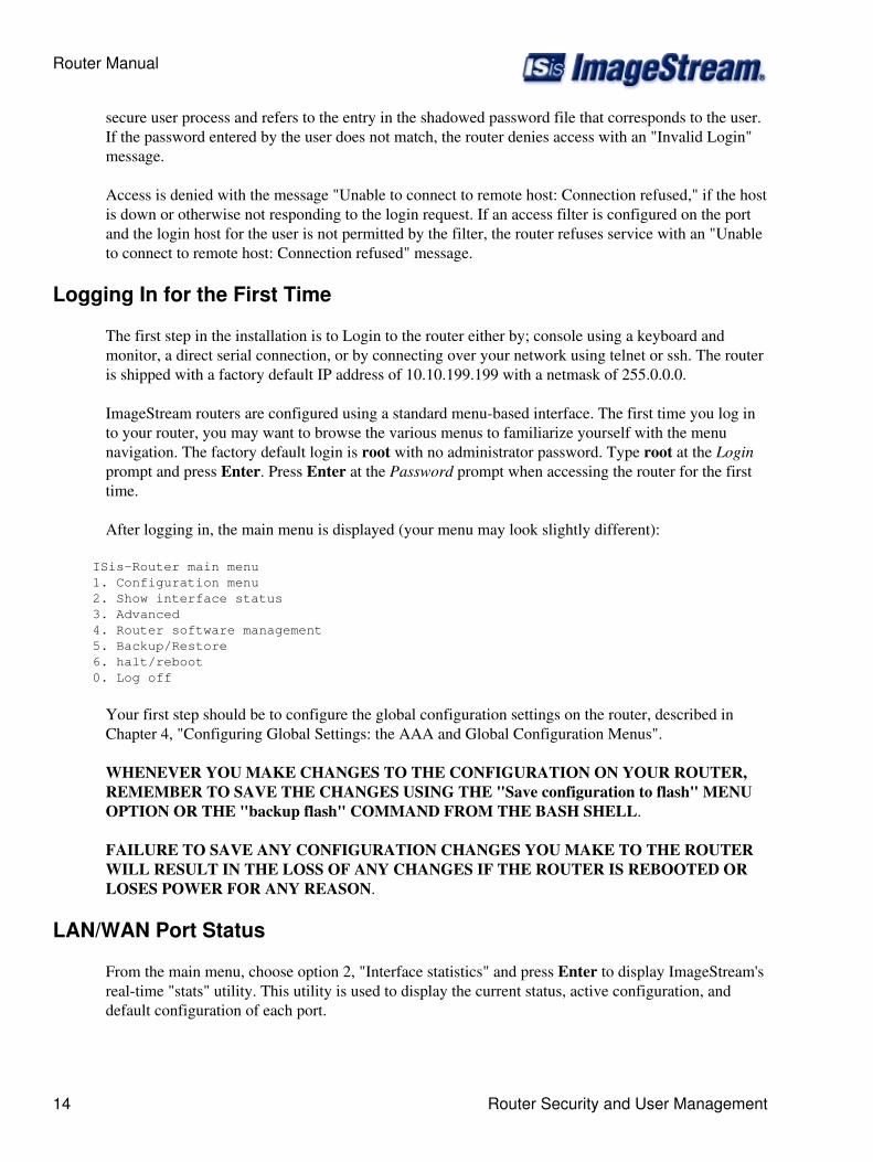
After logging in, the main menu is displayed (your menu may look slightly different):
ISis-Router main menu 1. Configuration menu 2. Show interface status 3. Advanced 4. Router software management 5. Backup/Restore 6. halt/reboot 0. Log off
Your first step should be to configure the global configuration settings on the router, described inChapter 4, "Configuring Global Settings: the AAA and Global Configuration Menus".
WHENEVER YOU MAKE CHANGES TO THE CONFIGURATION ON YOUR ROUTER,REMEMBER TO SAVE THE CHANGES USING THE "Save configuration to flash" MENUOPTION OR THE "backup flash" COMMAND FROM THE BASH SHELL.
FAILURE TO SAVE ANY CONFIGURATION CHANGES YOU MAKE TO THE ROUTERWILL RESULT IN THE LOSS OF ANY CHANGES IF THE ROUTER IS REBOOTED ORLOSES POWER FOR ANY REASON.
LAN/WAN Port Status
From the main menu, choose option 2, "Interface statistics" and press Enter to display ImageStream'sreal-time "stats" utility. This utility is used to display the current status, active configuration, anddefault configuration of each port.
Router Manual
14 Router Security and User Management

See Chapter 27, "Understanding The Interface Statistics (stats) Program" for more information aboutthis utility.
Configuring Global Setting : The AAA and GlobalConfiguration Menus
This chapter describes how to configure settings that the ImageStream router uses across all of itsports and interfaces.
This chapter discusses the following topics:
Setting the Administrative Password◊ Configuring the Router for TACACS+ Server Authentication◊ Setting the Hostname◊ Configuring Name Resolution◊ Configuring Local Event Logging◊ Configuring Remote Event Logging◊ Configuring Advanced Event Logging◊ Configuring the User-Configurable Startup Script◊ Configuring the Default Terminal Type◊ Configuring the Default Text Editor◊ Setting the System Time◊
After logging in, the main menu is displayed (your menu may look slightly different):
ISis-Router main menu 1. Configuration menu 2. Show interface status 3. Advanced 4. Router software management 5. Backup/Restore 6. halt/reboot 0. Log off
Your first steps should be to configure the Global Configuration Settings on the router. Select menuoption 1, Configuration menu, and press Enter to configure the router. The Configuration menushould appear (your menu may look slightly different):
Configuration menu 1. AAA (Password) Configuration 2. Global configuration 3. Network interface configuration 4. Firewall and QOS configuration 5. Service configuration 6. Dynamic routing configuration 7. Save configuration to flash 0. ISis-Router main menu
Next, select menu option 1, AAA (Password) Configuration, and press Enter to configure the routersLogin and Password settings. The AAA (Password) Configuration menu will be displayed(again, your
Router Manual
LAN/WAN Port Status 15
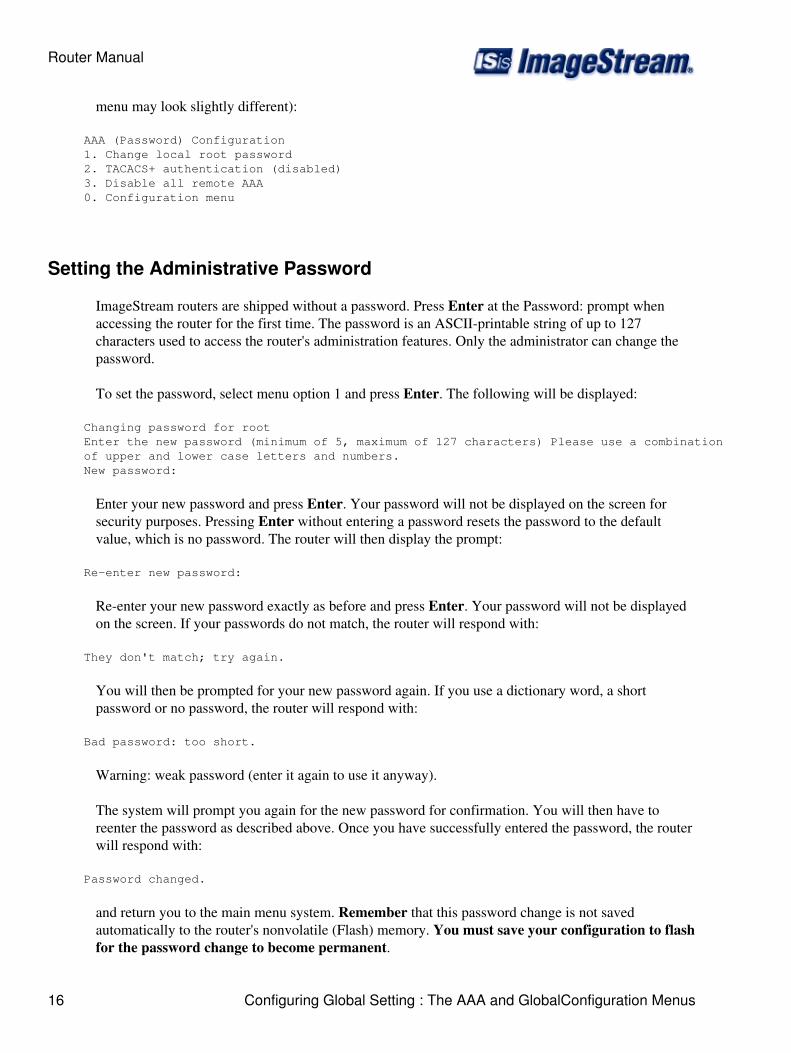
menu may look slightly different):
AAA (Password) Configuration 1. Change local root password 2. TACACS+ authentication (disabled) 3. Disable all remote AAA 0. Configuration menu
Setting the Administrative Password
ImageStream routers are shipped without a password. Press Enter at the Password: prompt whenaccessing the router for the first time. The password is an ASCII-printable string of up to 127characters used to access the router's administration features. Only the administrator can change thepassword.
To set the password, select menu option 1 and press Enter. The following will be displayed:
Changing password for root Enter the new password (minimum of 5, maximum of 127 characters) Please use a combination of upper and lower case letters and numbers. New password:
Enter your new password and press Enter. Your password will not be displayed on the screen forsecurity purposes. Pressing Enter without entering a password resets the password to the defaultvalue, which is no password. The router will then display the prompt:
Re-enter new password:
Re-enter your new password exactly as before and press Enter. Your password will not be displayedon the screen. If your passwords do not match, the router will respond with:
They don't match; try again.
You will then be prompted for your new password again. If you use a dictionary word, a shortpassword or no password, the router will respond with:
Bad password: too short.
Warning: weak password (enter it again to use it anyway).
The system will prompt you again for the new password for confirmation. You will then have toreenter the password as described above. Once you have successfully entered the password, the routerwill respond with:
Password changed.
and return you to the main menu system. Remember that this password change is not savedautomatically to the router's nonvolatile (Flash) memory. You must save your configuration to flashfor the password change to become permanent.
Router Manual
16 Configuring Global Setting : The AAA and GlobalConfiguration Menus
Configuring the Router for TACACS+ Server Authentication
ImageStream routers support centralized user authentication and login shell selection using aTerminal Access Controller Access Control System (TACACS+) server/database. When enabled, therouter will contact the TACACS+ server to authenticate users that attempt to log in to the router. Ifthe TACACS+ server does not have an entry for the user ID, or if the router cannot contact theTACACS+ server, then the router will check the local password file. Although the local password filecontains only the root administrative user, it is possible to create multiple levels of access to the routerwhen using a TACACS+ server for authentication.
You should only configure TACACS+ authentication if you have a valid TACACS+ server availableon your network. If you are unsure, do not configure this option.
To configure TACACS+ authentication select menu option 2, TACACS+ authentication (disabled),and press Enter. The following will be displayed:
Remember that you must configure your TACACS+ server. The router will use the local password as a fallback.
Enter the hostname or IP address of the primary TACACS+ server or leave blank to disable TACACS+ for AAA:
Enter the IP address or the fully qualified domain name (FQDN) for your primary TACACS+ serverand press Enter. For example, if your TACACS+ server is located at tacacs.imagestream.com, youwould enter tacacs.imagestream.com at the prompt. If you are attempting to clear a previousTACACS+ server configuration, then press Enter at the prompt without entering any information.
After entering the primary server, the router will display:
You may configure up to 3 additional TACACS+ servers.
Do you have additional TACACS+ servers to configure (y/N)?:
Note: If you have backup TACACS+ servers, follow the on-screen prompts to fill in the IP address orFully Qualified Domain Name (FQDN) of the backup server(s). After you have entered yourTACACS+ servers, the router will display:
Enter the encryption secret (all servers must use a common secret) or leave blank to disable encryption:
Note: If your TACACS+ server uses an encryption key, enter it here. The key must be the same for allservers. The router will not prompt you for alternate keys. If your TACACS+ server does not useencryption, then leave the entry blank and press Enter at the prompt. You will be prompted toconfirm that encryption should be disabled.
When you have entered the encryption secret information, the router will display:
Now rebuilding AAA configurations (/etc/pam.conf)...done.
and return you to the main menu system. Remember that this remote AAA change is not savedautomatically to the router's nonvolatile (Flash) memory. You must save your configuration to flashfor the hostname change to become permanent.
Router Manual
Configuring the Router for TACACS+ Server Authentication 17
Disabling Remote AAA Configurations
To disable any remote AAA configurations, select menu option 3, Disable all remote AAA, and pressEnter to reset the router to its original default AAA configuration (local password file only).
Global Configurations
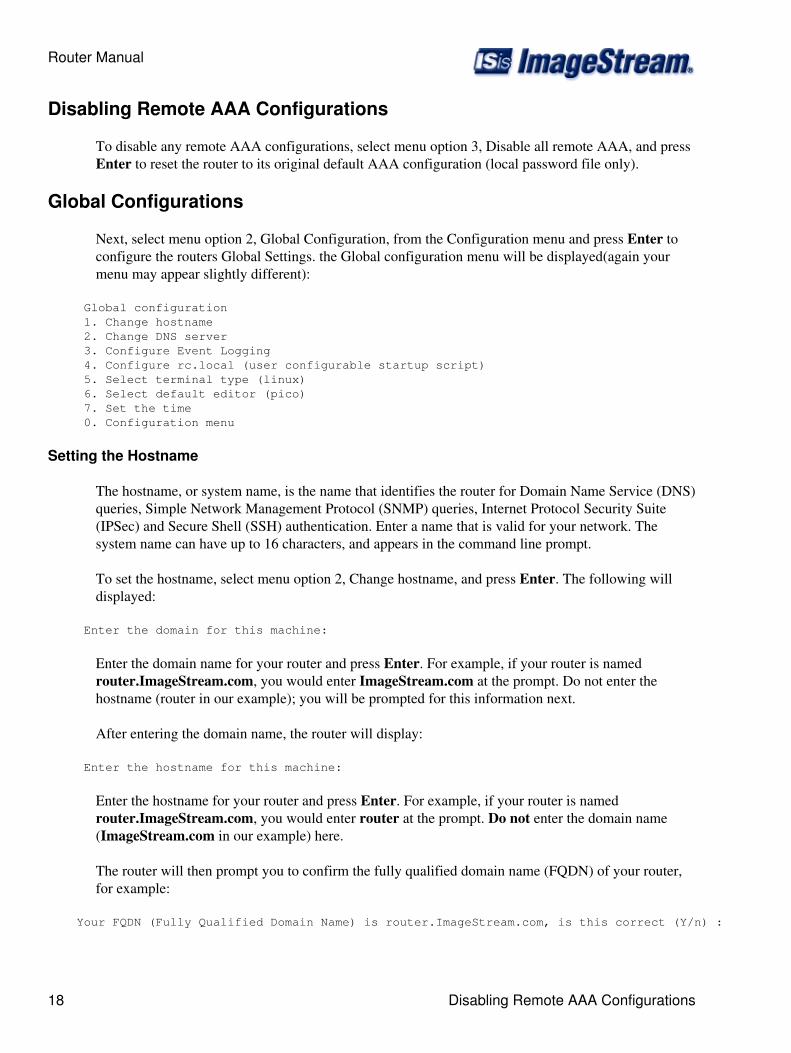
Next, select menu option 2, Global Configuration, from the Configuration menu and press Enter toconfigure the routers Global Settings. the Global configuration menu will be displayed(again yourmenu may appear slightly different):
Global configuration 1. Change hostname 2. Change DNS server 3. Configure Event Logging 4. Configure rc.local (user configurable startup script) 5. Select terminal type (linux) 6. Select default editor (pico) 7. Set the time 0. Configuration menu
Setting the Hostname
The hostname, or system name, is the name that identifies the router for Domain Name Service (DNS)queries, Simple Network Management Protocol (SNMP) queries, Internet Protocol Security Suite(IPSec) and Secure Shell (SSH) authentication. Enter a name that is valid for your network. Thesystem name can have up to 16 characters, and appears in the command line prompt.
To set the hostname, select menu option 2, Change hostname, and press Enter. The following willdisplayed:
Enter the domain for this machine:
Enter the domain name for your router and press Enter. For example, if your router is namedrouter.ImageStream.com, you would enter ImageStream.com at the prompt. Do not enter thehostname (router in our example); you will be prompted for this information next.
After entering the domain name, the router will display:
Enter the hostname for this machine:
Enter the hostname for your router and press Enter. For example, if your router is namedrouter.ImageStream.com, you would enter router at the prompt. Do not enter the domain name(ImageStream.com in our example) here.
The router will then prompt you to confirm the fully qualified domain name (FQDN) of your router,for example:
Your FQDN (Fully Qualified Domain Name) is router.ImageStream.com, is this correct (Y/n) :
Router Manual
18 Disabling Remote AAA Configurations

Press Y or y if the entry displayed is correct. Press N or n if the entry displayed is incorrect. PressingN or n will erase your entries and the router will prompt you again for the domain name andhostname. If you pressed Y or y, the router will display the hostname you have entered, for example:
Hostname changed to router.ImageStream.com.
and return you to the Global configuration menu system. Remember that this hostname change is notsaved automatically to the router's nonvolatile (Flash) memory. You must save your configurationto flash for the hostname change to become permanent.
Configuring Name Resolution
The ImageStream router can work with a Domain Name Server (DNS). Chapter 31, BasicNetworking, describes this name service. If you do not set a valid domain name resolution server, youwill not be able to use the automatic software update feature on your router.
To set the DNS server, select menu option 2, Change DNS server, and press Enter. The followingwill be displayed:
Enter the domain for this machine:
Enter the domain name for your router and press Enter. For example, if your router is namedrouter.ImageStream.com, you would enter ImageStream.com at the prompt. Do not enter thehostname (router in our example). This domain name does not necessarily have to be the samedomain as the router's domain name. This value will be the first domain searched to resolve names.For example, if you enter the command telnet router from the command line, the DNS resolver onthe router will search ImageStream.com if that value is entered in response to the question above.
Once you have entered the domain name, you will be prompted for the IP address of the domain nameserver for your network:
Enter the nameserver IP address for this router:
Enter the IP address of the nameserver for your router and press Enter. For example, if yournameserver is located at the IP address 192.168.100.1, you would enter 192.168.100.1 at the prompt.The router will display:
Now writing the /etc/resolv.conf file...done.
and return you to the Global configuration menu system. If you need to add additional search domainsor name servers, you can do this from the command line. Enter the command /etc/editor/etc/resolv.conf. This will open the standard Linux resolv.conf file in your default text editor. This isan advanced option, and you should only edit this file if you are familiar with the resolv.conf fileunder Linux. Remember that any changes to the DNS server are not saved automatically to therouter's nonvolatile (Flash) memory. You must save your configuration to flash for the changes tobecome permanent.
Router Manual
Global Configurations 19

Configuring Local Event Logging
The ImageStream router can log messages to a local file, to the console or to remote devices orlogging servers via the standard syslog facility. By default, system messages are logged only to a localfile on the router.
Select menu option 3, Configure Event Logging, from the Global Configuration menu and pressEnter to configure the router's global settings. The Configuration Event Logging menu will bedisplayed(again, your menu may look slightly different):
Configure Event Logging 1. Configure remote event logging 2. Enable local event logging 3. Configure advanced event logging 0. Global configuration
To configure local event logging, select menu option 3 and press Enter. The following will bedisplayed:
Enabling local logging will create an automatically rotated system logfile accessible from the router's Advanced menu or in the file '/var/log/syslog'.
Would you like to enable local system logging? Press 'Y' or 'y' to enable system logging or press Enter to disable system logging and remove old logs (y/N).
Follow the on-screen prompts to enable or disable local system logging. The logfile created by therouter will not fill the router's virtual file system. By default, the system will log to /var/log/syslog,with 1 backup file. Files will rotate every 24 hours or after 250KB of log information, whichevercomes first. For debugging purposes, ImageStream recommends that you leave local system loggingenabled by pressing Y at the prompt.
The router will display the following:
Enabling console logging will send all messages to both remote and console root logins.
Woulds you like to enable console logging? Press 'Y' or 'y' to enable logging or press Enter to disable console logging (y/N).
Note: Enabling console logging will print all system messages on your screen when you are logged inas the root user. For some users, the number of messages generated may make it difficult to use therouter, so this option is disabled by default. If the appearance of messages on your console does notaffect your use of the router, ImageStream recommends enabling this option. Follow the on-screenprompts to enable or disable console logging. The router will display the following:
Now writing the /etc/syslog.conf file...done.
and return you to the menu system. Remember that this change is not saved automatically to therouter's nonvolatile (Flash) memory. You must save your configuration to flash for the change tobecome permanent.
Router Manual
20 Global Configurations
Configuring Remote Event Logging
The ImageStream router can log messages to a local file, to the console or to remote devices orlogging servers via the standard syslog facility. By default, system messages are logged only to a localfile on the router.
To configure the routers global settings select menu option 3, Configure Event Logging, from theGlobal Configuration menu and press Enter. The Configure Event Logging menu will bedisplayed(again, your menu may look slightly different):
Configure Event Logging 1. Configure remote event logging 2. Enable local event logging 3. Configure advanced event logging 0. Global configuration
To set up a remote logging server, select menu option 1 and Enter. The router will display thefollowing:
Remember that you must configure your remote syslog server to accept syslog data from remote systems. Most syslog implementations use '-r' to enable this function. Consult your server documentation or man pages.
Enter name or IP address of machine to log to, or leave blank to disable remote logging:
Enter either the IP address or FQDN of the remote logging machine and press Enter. For example, ifthe remote logging machine is server.imagestream.com and its IP address is 192.168.100.1, youwould enter either of those values at the prompt. If you leave the entry blank, remote logging will bedisabled. The router will display:
Now writing the /etc/syslog.conf file...done.
and return you to the Configuration Event menu system. Remember that this change is not savedautomatically to the router's nonvolatile (Flash) memory. You must save your configuration to flashfor the change to become permanent.
Press menu option 0 to return to the Global configuration menu.
Configuring Advanced Event Logging
For users familiar with the UNIX syslog facility, the Event Logging menu includes an advancedconfiguration option. This configuration file allows you to configure advanced logging parameters forlocal and remote logging. The default configuration file includes two types of examples: remotelogging using a "local" facility and local logging using log rotation.
Select menu option 3, Configure Event Logging, from the Global Configuration menu to configurethe router's global settings. The Configuration Event Logging menu will be displayed(again, yourmenu may look slightly different):
Configure Event Logging 1. Configure remote event logging 2. Enable local event logging
Router Manual
Global Configurations 21

3. Configure advanced event logging 0. Global configuration
To configure the Remote Event Logging, select menu option 3 and press Enter. The router willdisplay the syslog.conf.local file. The following example shows the use of a local facility for logseparation on a remote server:
local0.* @server.imagestream.com
The command above directs the router to send all local0 messages to the machine at the FQDNserver.imagestream.com. The remote logging server can be configured to send any local0 messages toa separate data file for easier analysis. Any local facility from 0 to 7 is valid. The local facilities canbe used to create separate log files directly on the router as well.
The next example shows the use of ImageStream's log rotation options:
*.* /var/log/syslog rotate,size=250k,age=24,files=1
The entries in the syslog.conf.local file follow the format:
<facilities to log> <output file/destination> <logging options>
Each section should be separated by a space or a tab. The logging options are separated by a comma.You may not use a tab or a space in the output file/destination. The available logging options are:
rotate - Signals the syslog daemon to automatically rotate log files. If you do not provide anyother options, then syslog will rotate the log file after it reaches 1 MB in size and willmaintain 5 spare/backup files.
sizek - Specified in "k", this option tells the syslog daemon the size at which files should berotated.
age - Specified in hours, this option tells the syslog daemon how often to automatically rotatefiles. For example, age=24 signals syslog to rotate the file every 24 hours regardless of size.
files - This option tells the syslog daemon how many spare/backup files to maintain. Forexample, files=2 creates 2 spare/backup files (syslog.1 and syslog.2) in addition to the mainlog file.
After saving the file and exiting, the router will display:
Now writing the /etc/syslog.conf file...done.
and return you to the Configure Event menu system. Remember that this change is not savedautomatically to the router's nonvolatile (Flash) memory. You must save your configuration to flashfor the change to become permanent.
Press menu option 3 and press Enter to return to the Global Configuration menu.
Router Manual
22 Global Configurations
Configuring the User-Configurable Startup Script
The ImageStream Router supports the use of user-defined commands or scripts on startup. To enableany user scripts or issue special commands, choose option 4 from the Global configuration menu andpress Enter: The Global configuration menu will be displayed(again, your display may appearslightly different).
Global configuration 1. Change hostname 2. Change DNS server 3. Configure Event Logging 4. Configure rc.local (user configurable startup script) 5. Select terminal type (linux) 6. Select default editor (pico) 7. Set the time 0. Configuration menu
This will open the rc.local file in your default text editor. This is an advanced option, and you shouldonly edit this file if you are familiar with the rc.local file under Linux. Remember that any changesto the rc.local file are not saved automatically to the router?s nonvolatile (Flash) memory. You mustsave your configuration to flash for the changes to become permanent.
Configuring the Default Terminal Type
The ImageStream Router supports thirteen common terminal types for use in displaying the router'smenu and command line system to the connected display. The default value of vt100 should work formost users. This is an advanced option, and you should only change this setting if you are familiarwith terminal types and need support for a different type.
To set the default terminal type, select menu option 6 and press Enter. The following menu will bedisplayed:
Set your terminal type (vt100) 1. vt100 (default) 2. vt102 3. vt220 4. linux (linux systems only) 5. Other (May cause software to be inoperable) 0. Global configuration
To select the vt100 terminal type or the corresponding number to a different terminal type, select themenu option that matches your terminal type. Assuming you chose option 1 the following would bedisplayed:
vt100 selected as the default terminal type.
And return you to the above menu. Remember that any change in the terminal type is not savedautomatically to the router's nonvolatile (Flash) memory. You must save your configuration to flashfor the hostname change to become permanent.
Router Manual
Configuring the User-Configurable Startup Script 23
To return to the Global configuration menu, select menu option 0 and press Enter the Globalconfiguration menu will be displayed.
Configuring the Default Text Editor
The ImageStream Router supports two common text editors for use in configuring the system, vi andpico. Both text editors are available from the command line. The menu system defaults to pico. Thepico editor is recommended for most users. If you are an advanced administrator familiar with vi, thenselect this option as your default.
To set the default text editor, select menu option 6 and press Enter. The following menu will bedisplayed:
Select default editor (pico) 1. Pico 2. vi (for advanced users) 0. Global configuration
Select either menu option 1 or 2 to choose the editor of your choice and press Enter. The router willdisplay (assuming Pico is selected) the following:
pico selected as the default editor.
Then return you to the above menu. Remember that any change in the default editor is not savedautomatically to the router's nonvolatile (Flash) memory. You must save your configuration to flashfor the hostname change to become permanent.
To return to the Global configuration menu, select menu option 0 and press Enter. The Globalconfiguration menu will be displayed.
Setting the System Time
The ImageStream Router you receive has a system clock. This clock is used to calculate deviceuptimes and downtimes, log system messages via syslog and maintain modification times on files.The system clock can be synchronized with a server running the Network Time Protocol (NTP).
To set the system time, select menu option 7 and press Enter. The router will display the current timeand prompt you if you want to synchronize the system time with a network time server.
Setting the System Time Manually
To set the system time manually, press N and Enter. The router will display the following:
Please enter the date in this format (MMDDhhmmCCYY):
Enter the date in the specified format. For example, if the date is September 10, 2002 at 7:10 a.m.,enter:
Router Manual
24 Configuring the Default Terminal Type

091007102002
The router will then prompt you to confirm the date and time that you entered, for example:
You have entered 09-10-2002 07:10, is this correct (Y/n) :
Press 'Y' or 'y' if the entry displayed is correct. Press 'N' or 'n' if the entry displayed is incorrect.Pressing 'N' or 'n' will erase your entries and the router will prompt you again for the system time. Ifyou press 'Y' or 'y', the router will ask for the local time zone:
Please enter the time zone abbreviation ('UTC' for Coordinated Universal Time) :
Enter the correct abbreviation for the time zone you want to use with the router. For example, CentralEuropean Summer Time is entered as CEST. Next, the router will ask for the time offset from UTC:
Please enter the UTC offset for your time zone ('-8' for Pacific Standard Time) :
Enter a + or a - and the number of hours between your local time zone and UTC. The router will thenprompt you to confirm the time zone and offset. Once you confirm the time zone and offset, the routerwill display the time:
Tue Sep 10 07:10:00 PST 2002
Then return you to the above menu. The system time will be automatically changed on the router andsaved to the router's nonvolatile (Flash) memory.
To return to the Configuration menu, select menu option 0 and press Enter. The Configuration menuwill be displayed.
Configuring a LAN Interface
This chapter describes how to configure the ImageStream router Ethernet and Token Ring interfaces,Ethernet VLAN subinterfaces and VRRP, and includes the following topics:
Understanding the Network Interface Configuration File◊ Default LAN Interface Configuration◊ Customizing the Configuration◊ Configuring Additional Ethernet Devices◊ Configuring Token Ring Interfaces◊
Before configuring the Ethernet or Token Ring interface, you must make the appropriate cablingconnection for your needs. Refer to the hardware installation guide for your ImageStream product forinformation on making the LAN connection. See the Command Reference for more detailedcommand descriptions and instructions.
Configuration menu 1. AAA (Password) Configuration 2. Global configuration 3. Network interface configuration 4. Firewall and QOS configuration
Router Manual
Setting the System Time Manually 25
5. Service configuration 6. Dynamic routing configuration 7. Save configuration to flash 0. ISis-Router main menu
Next, select the "Network interface configuration" option by pressing 3 and Enter. This will open theImageStream router?s primary configuration file, wan.conf in the default editor. The wan.conf file isalso accessible from the command line in the /usr/local/sand directory.
Understanding the Network Interface Configuration File
wan.conf is the primary configuration file used by ImageStream's Inetics? driver componentarchitecture. Inetics handles configuration and management of all LAN and WAN devices onImageStream routers. For more information on ImageStream's Inetics technology, visit theImageStream Web site at http://www.imagestream.com. See the Command Reference for moredetailed command descriptions and instructions.
The default wan.conf file is:
! version 2.00 ! interface Ethernet0 ip address 10.10.199.199 255.0.0.0!interface Serial0 shutdown description Port 0 encapsulation hdlc ip address 192.168.10.1 255.255.255.252!# Set the default route via Serial0 using the device #ip route add 0.0.0.0/0 dev Serial0 # Set the default route via Serial0 using an IP #ip route add default via 192.168.10.2 ! end
The values in the default file are explained below.
version 2.00 - Denotes the version number of the configuration file and driver set. This value is set byImageStream and should not be changed or modified.
interface Ethernet0 - Denotes the start of the configuration section for the first Ethernet device inyour system. All commands that follow this line until the next ! mark will be applied to Ethernet0.
ip address 10.10.199.199 255.0.0.0 - Specifies the IP address and netmask for Ethernet0.
!, end - Signifies the end of a configuration section or the end of the wan.conf file. You must includea "!" to delimit each section of the configuration file and an "end" statement at the end of the file.
Router Manual
26 Configuring a LAN Interface

interface Serial0 - Denotes the start of the configuration section for the first Serial port in yoursystem. All commands that follow this line until the next ! mark will be applied to Serial0.
shutdown - Instructs the router not to start this port when Inetics is started or reloaded.
description Port 0 - Sets a description for this device. The description is optional used for reportingpurposes in other utilities. Setting a value here does not affect the operation of the port.
encapsulation hdlc - Specifies the Cisco HDLC protocol for this serial port.
ip address 192.168.10.1 255.255.255.252 - Specifies the IP address and netmask for Serial0.
# Set the default route via Serial0 using the device - A comment inserted in the configuration file.Lines that begin with # or ! are ignored by Inetics when starting or reloading configurations.
#ip route add 0.0.0.0/0 dev Serial0 - A route statement setting the default route to the Serial0 device.This syntax can not be used to route via Ethernet interfaces properly. Note that this command iscommented out, so it will be ignored by Inetics.
#ip route add default via 192.168.10.2 - A route statement setting the default route to the IP addressof 192.168.10.2. Note that this command is commented out, so it will be ignored by Inetics. Thiscommand also uses the alternate default route designator of default instead of the numeric 0.0.0.0/0.The designators are equivalent.
Default LAN Interface Configuration
The default values of the 10/100 Mbps Ethernet and Gigabit Ethernet on-board and expansion cardsare as follows:
On-board Ethernet ports are always the first device(s) in the router. A router with oneon-board Ethernet port and one expansion port will use Ethernet0 for the onboard port andEthernet1 for the expansion port.
◊
All 10/100 Mbps Ethernet and Gigabit Ethernet ports are enabled. No port description isconfigured for any port.
◊
All 10/100 Mbps Ethernet ports are set to autonegotiate speed and duplex. All GigabitEthernet ports are set to full duplex autonegotiation.
◊
VLAN's are not configured.◊ Bridging is not configured.◊ VRRP is not configured.◊
Remember that default settings are not necessarily shown in the configuration file.
Customizing the Configuration
To customize the Ethernet port configurations, complete the following sections. The ordering of thecommands is done by convention, but a specific order is not required. Likewise, all configurations areindented to make configurations easy to read, but indentation is not required. In general, ImageStreamfollows this ordering convention:
Router Manual
Understanding the Network Interface Configuration File 27
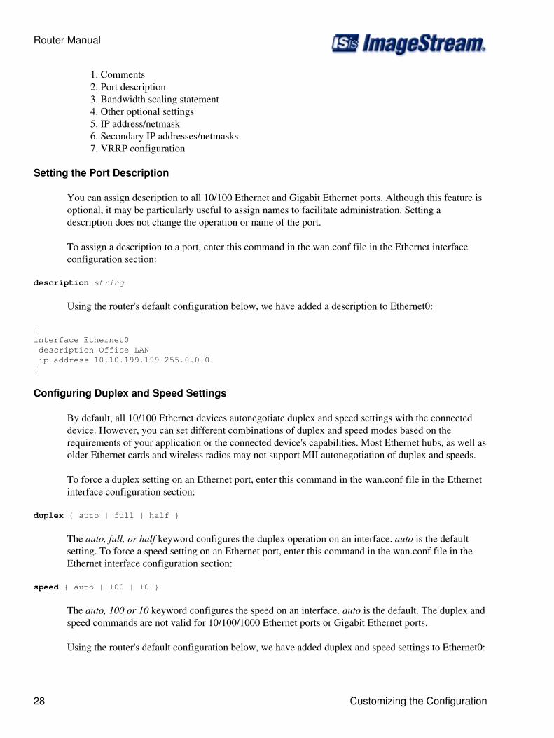
Comments1. Port description2. Bandwidth scaling statement3. Other optional settings4. IP address/netmask5. Secondary IP addresses/netmasks6. VRRP configuration7.
Setting the Port Description
You can assign description to all 10/100 Ethernet and Gigabit Ethernet ports. Although this feature isoptional, it may be particularly useful to assign names to facilitate administration. Setting adescription does not change the operation or name of the port.
To assign a description to a port, enter this command in the wan.conf file in the Ethernet interfaceconfiguration section:
description string
Using the router's default configuration below, we have added a description to Ethernet0:
! interface Ethernet0 description Office LAN ip address 10.10.199.199 255.0.0.0!
Configuring Duplex and Speed Settings
By default, all 10/100 Ethernet devices autonegotiate duplex and speed settings with the connecteddevice. However, you can set different combinations of duplex and speed modes based on therequirements of your application or the connected device's capabilities. Most Ethernet hubs, as well asolder Ethernet cards and wireless radios may not support MII autonegotiation of duplex and speeds.
To force a duplex setting on an Ethernet port, enter this command in the wan.conf file in the Ethernetinterface configuration section:
duplex { auto | full | half }
The auto, full, or half keyword configures the duplex operation on an interface. auto is the defaultsetting. To force a speed setting on an Ethernet port, enter this command in the wan.conf file in theEthernet interface configuration section:
speed { auto | 100 | 10 }
The auto, 100 or 10 keyword configures the speed on an interface. auto is the default. The duplex andspeed commands are not valid for 10/100/1000 Ethernet ports or Gigabit Ethernet ports.
Using the router's default configuration below, we have added duplex and speed settings to Ethernet0:
Router Manual
28 Customizing the Configuration

! interface Ethernet0 description Office LAN duplex auto speed auto ip address 10.10.199.199 255.0.0.0 !
The table below describes the relationship between different combinations of the duplex and speedmodes. The specified duplex command configured with the specified speed command produces theresulting action on the Ethernet port.
Relationship Between duplex and speed Commands
duplex Command speed Command Resulting Action by Ethernet Portduplex auto speed auto Autonegotiates both speed and duplex modes
duplex half or full speed auto Autonegotiates both speed and duplex modesduplex auto speed 10 Forces 10 Mbps and Autonegotiates duplex modeduplex auto speed 100 Forces 100 Mbps and Autonegotiates duplex modeduplex half speed 10 Forces 10 Mbps and half duplexduplex full speed 10 Forces 10 Mbps and full duplexduplex half speed 100 Forces 100 Mbps and half duplexduplex full speed 100 Forces 100 Mbps and full duplex
Setting the IP Address and Netmask
During the initial installation process, you will set the IP address and netmask for the Ethernetinterface. To change the IP address and netmask of the Ethernet interface from the default, modify theip address command. The syntax of this command is
ip address ipaddress netmask
Set the IP address to the address to be used by the router on your network. If you have divided yournetwork into subnets, enter the subnet mask that identifies how your network addresses are dividedbetween the network portion and the host portion.
Using the default configuration above, we have set the Ethernet0 IP address to 10.10.10.1 with a ClassC netmask (/24, or 255.255.255.0). You will need to substitute your address and netmask for yournetwork.
! interface Ethernet0 description Office LAN duplex auto speed auto ip address 10.10.10.1 255.255.255.0!
Router Manual
Customizing the Configuration 29
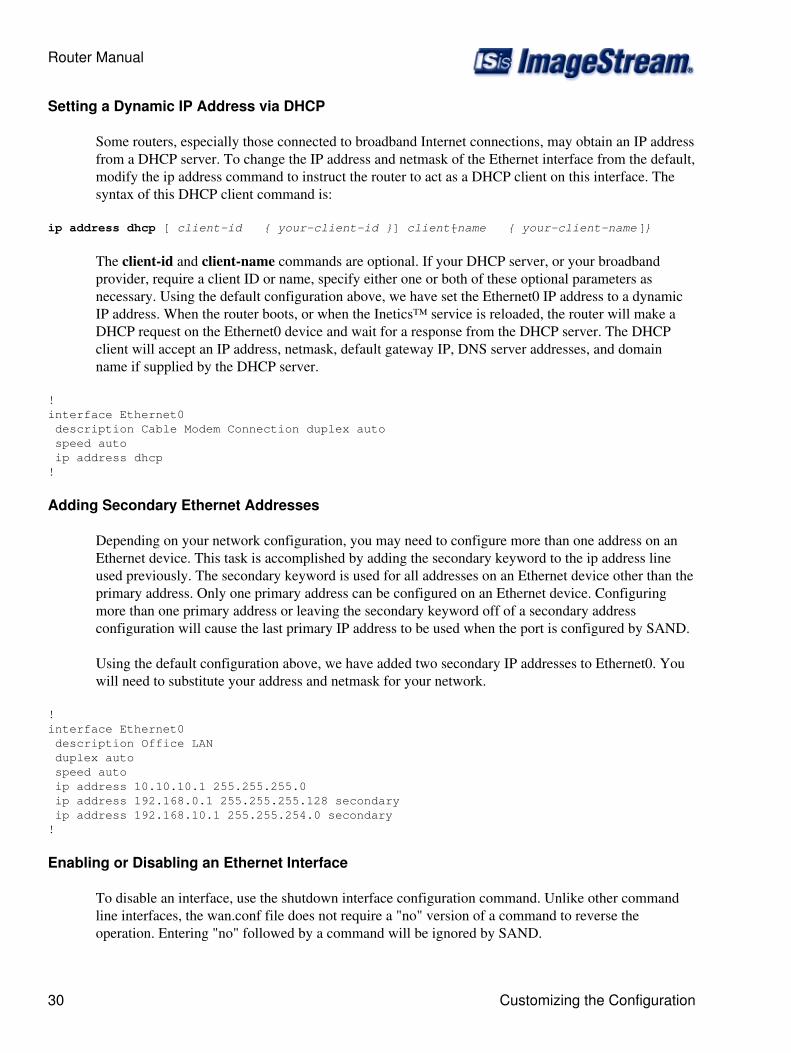
Setting a Dynamic IP Address via DHCP
Some routers, especially those connected to broadband Internet connections, may obtain an IP addressfrom a DHCP server. To change the IP address and netmask of the Ethernet interface from the default,modify the ip address command to instruct the router to act as a DHCP client on this interface. Thesyntax of this DHCP client command is:
ip address dhcp [ client-id { your-client-id }] [ client-name { your-client-name }]
The client-id and client-name commands are optional. If your DHCP server, or your broadbandprovider, require a client ID or name, specify either one or both of these optional parameters asnecessary. Using the default configuration above, we have set the Ethernet0 IP address to a dynamicIP address. When the router boots, or when the Inetics™ service is reloaded, the router will make aDHCP request on the Ethernet0 device and wait for a response from the DHCP server. The DHCPclient will accept an IP address, netmask, default gateway IP, DNS server addresses, and domainname if supplied by the DHCP server.
! interface Ethernet0 description Cable Modem Connection duplex auto speed auto ip address dhcp!
Adding Secondary Ethernet Addresses
Depending on your network configuration, you may need to configure more than one address on anEthernet device. This task is accomplished by adding the secondary keyword to the ip address lineused previously. The secondary keyword is used for all addresses on an Ethernet device other than theprimary address. Only one primary address can be configured on an Ethernet device. Configuringmore than one primary address or leaving the secondary keyword off of a secondary addressconfiguration will cause the last primary IP address to be used when the port is configured by SAND.
Using the default configuration above, we have added two secondary IP addresses to Ethernet0. Youwill need to substitute your address and netmask for your network.
! interface Ethernet0 description Office LAN duplex auto speed auto ip address 10.10.10.1 255.255.255.0 ip address 192.168.0.1 255.255.255.128 secondary ip address 192.168.10.1 255.255.254.0 secondary !
Enabling or Disabling an Ethernet Interface
To disable an interface, use the shutdown interface configuration command. Unlike other commandline interfaces, the wan.conf file does not require a "no" version of a command to reverse theoperation. Entering "no" followed by a command will be ignored by SAND.
Router Manual
30 Customizing the Configuration
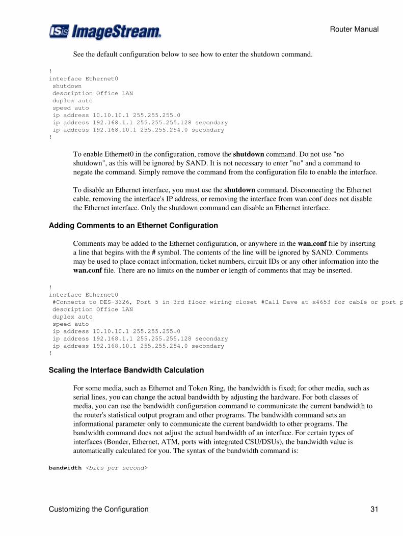
See the default configuration below to see how to enter the shutdown command.
!interface Ethernet0 shutdown description Office LAN duplex auto speed auto ip address 10.10.10.1 255.255.255.0 ip address 192.168.1.1 255.255.255.128 secondary ip address 192.168.10.1 255.255.254.0 secondary !
To enable Ethernet0 in the configuration, remove the shutdown command. Do not use "noshutdown", as this will be ignored by SAND. It is not necessary to enter "no" and a command tonegate the command. Simply remove the command from the configuration file to enable the interface.
To disable an Ethernet interface, you must use the shutdown command. Disconnecting the Ethernetcable, removing the interface's IP address, or removing the interface from wan.conf does not disablethe Ethernet interface. Only the shutdown command can disable an Ethernet interface.
Adding Comments to an Ethernet Configuration
Comments may be added to the Ethernet configuration, or anywhere in the wan.conf file by insertinga line that begins with the # symbol. The contents of the line will be ignored by SAND. Commentsmay be used to place contact information, ticket numbers, circuit IDs or any other information into thewan.conf file. There are no limits on the number or length of comments that may be inserted.
! interface Ethernet0 #Connects to DES-3326, Port 5 in 3rd floor wiring closet #Call Dave at x4653 for cable or port problems description Office LAN duplex auto speed auto ip address 10.10.10.1 255.255.255.0 ip address 192.168.1.1 255.255.255.128 secondary ip address 192.168.10.1 255.255.254.0 secondary !
Scaling the Interface Bandwidth Calculation
For some media, such as Ethernet and Token Ring, the bandwidth is fixed; for other media, such asserial lines, you can change the actual bandwidth by adjusting the hardware. For both classes ofmedia, you can use the bandwidth configuration command to communicate the current bandwidth tothe router's statistical output program and other programs. The bandwidth command sets aninformational parameter only to communicate the current bandwidth to other programs. Thebandwidth command does not adjust the actual bandwidth of an interface. For certain types ofinterfaces (Bonder, Ethernet, ATM, ports with integrated CSU/DSUs), the bandwidth value isautomatically calculated for you. The syntax of the bandwidth command is:
bandwidth <bits per second>
Router Manual
Customizing the Configuration 31

Using the default example from above, you can see how we have added a bandwidth of 5 Mbps to the"Connection to co-lo" interface, Ethernet1:
! interface Ethernet0 #Connects to DES-3326, Port 5 in 3rd floor wiring closet #Call Dave at x4653 for cable or port problems description Office LAN duplex auto speed auto ip address 10.10.10.1 255.255.255.0 ip address 192.168.1.1 255.255.255.128 secondary ip address 192.168.10.1 255.255.254.0 secondary ! interface Ethernet1 #NOC phone: 800-555-1212 - Our account #58935 description Connection to co-lo bandwidth 5000000 ip address 63.67.72.155 255.255.255.0 !
Configuring Additional Ethernet Devices
If your router is equipped with multiple Ethernet devices, you can add additional interfaceconfigurations to the wan.conf file. Although the order of the devices in the file does not matter,ImageStream by convention keeps the interfaces in order.
Additional Ethernet devices are configured in the same manner as the on-board Ethernet0 device. Addan additional interface command for each additional Ethernet port, separating each section with a !symbol. The syntax of the interface command is:
interface DeviceName
Using the default example above you can see how we added a second Ethernet port at Ethernet1.
! interface Ethernet0 #Connects to DES-3326, Port 5 in 3rd floor wiring closet #Call Dave at x4653 for cable or port problems description Office LAN duplex auto speed auto ip address 10.10.10.1 255.255.255.0 ip address 192.168.1.1 255.255.255.128 secondary ip address 192.168.10.1 255.255.254.0 secondary ! interface Ethernet1 #NOC phone: 800-555-1212 - Our account #58935 description Connection to co-lo bandwidth 5000000 ip address 63.67.72.155 255.255.255.0!interface Ethernet2 description public servers ip address 20.215.25.1 255.255.254.0!
Router Manual
32 Customizing the Configuration
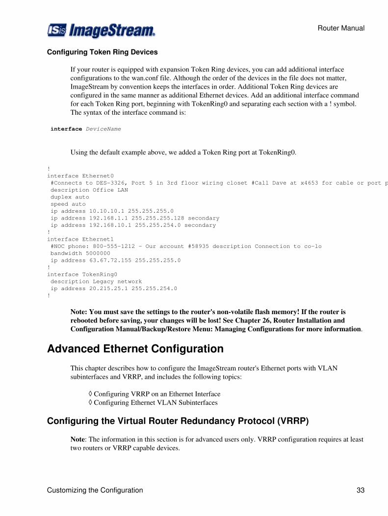
Configuring Token Ring Devices
If your router is equipped with expansion Token Ring devices, you can add additional interfaceconfigurations to the wan.conf file. Although the order of the devices in the file does not matter,ImageStream by convention keeps the interfaces in order. Additional Token Ring devices areconfigured in the same manner as additional Ethernet devices. Add an additional interface commandfor each Token Ring port, beginning with TokenRing0 and separating each section with a ! symbol.The syntax of the interface command is:
interface DeviceName
Using the default example above, we added a Token Ring port at TokenRing0.
! interface Ethernet0 #Connects to DES-3326, Port 5 in 3rd floor wiring closet #Call Dave at x4653 for cable or port problems description Office LAN duplex auto speed auto ip address 10.10.10.1 255.255.255.0 ip address 192.168.1.1 255.255.255.128 secondary ip address 192.168.10.1 255.255.254.0 secondary ! interface Ethernet1 #NOC phone: 800-555-1212 - Our account #58935 description Connection to co-lo bandwidth 5000000 ip address 63.67.72.155 255.255.255.0!interface TokenRing0 description Legacy network ip address 20.215.25.1 255.255.254.0!
Note: You must save the settings to the router's non-volatile flash memory! If the router isrebooted before saving, your changes will be lost! See Chapter 26, Router Installation andConfiguration Manual/Backup/Restore Menu: Managing Configurations for more information.
Advanced Ethernet Configuration
This chapter describes how to configure the ImageStream router's Ethernet ports with VLANsubinterfaces and VRRP, and includes the following topics:
Configuring VRRP on an Ethernet Interface◊ Configuring Ethernet VLAN Subinterfaces◊
Configuring the Virtual Router Redundancy Protocol (VRRP)
Note: The information in this section is for advanced users only. VRRP configuration requires at leasttwo routers or VRRP capable devices.
Router Manual
Customizing the Configuration 33
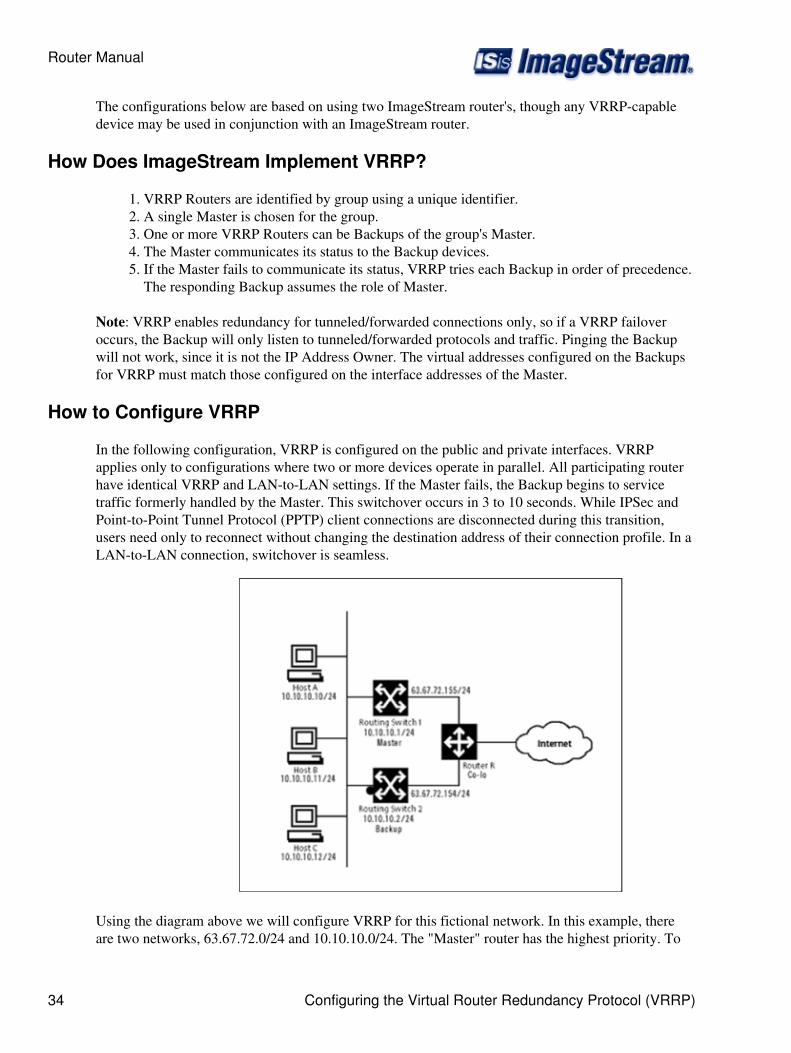
The configurations below are based on using two ImageStream router's, though any VRRP-capabledevice may be used in conjunction with an ImageStream router.
How Does ImageStream Implement VRRP?
VRRP Routers are identified by group using a unique identifier.1. A single Master is chosen for the group.2. One or more VRRP Routers can be Backups of the group's Master.3. The Master communicates its status to the Backup devices.4. If the Master fails to communicate its status, VRRP tries each Backup in order of precedence.The responding Backup assumes the role of Master.
5.
Note: VRRP enables redundancy for tunneled/forwarded connections only, so if a VRRP failoveroccurs, the Backup will only listen to tunneled/forwarded protocols and traffic. Pinging the Backupwill not work, since it is not the IP Address Owner. The virtual addresses configured on the Backupsfor VRRP must match those configured on the interface addresses of the Master.
How to Configure VRRP
In the following configuration, VRRP is configured on the public and private interfaces. VRRPapplies only to configurations where two or more devices operate in parallel. All participating routerhave identical VRRP and LAN-to-LAN settings. If the Master fails, the Backup begins to servicetraffic formerly handled by the Master. This switchover occurs in 3 to 10 seconds. While IPSec andPoint-to-Point Tunnel Protocol (PPTP) client connections are disconnected during this transition,users need only to reconnect without changing the destination address of their connection profile. In aLAN-to-LAN connection, switchover is seamless.
Using the diagram above we will configure VRRP for this fictional network. In this example, thereare two networks, 63.67.72.0/24 and 10.10.10.0/24. The "Master" router has the highest priority. To
Router Manual
34 Configuring the Virtual Router Redundancy Protocol (VRRP)
keep things simple, assume that all of the network segments use the same physical topology.Customers with dynamic routing environments (using BGP, OSPF or RIP) should not use virtualaddresses from a VRRP ID in the dynamic routing configuration.
"Master" router configuration:
! interface Ethernet0 #Connects to DES-3326, Port 5 in 3rd floor wiring closet #Call Dave at x4653 for cable or port problems description Office LAN ip address 10.10.10.1 255.255.255.0 ip address 192.168.1.1 255.255.255.128 secondary ip address 192.168.10.1 255.255.254.0 secondary vrrp 1 ip 10.10.10.3 vrrp 1 ip 63.67.72.155 secondary vrrp 1 priority 200 vrrp 1 authentication isis!interface Ethernet1 #NOC phone: 800-555-1212 - Our account #58935 description Connection to co-lo ip address 63.67.72.155 255.255.255.0!
"Backup" router configuration:
! interface Ethernet0 description Office LAN ip address 10.10.10.2 255.255.255.0 vrrp 1 ip 10.10.10.3 vrrp 1 ip 63.67.72.155 secondary vrrp 1 priority 100 vrrp 1 authentication isis!interface Ethernet1 description Connection to co-lo ip address 63.67.72.154 255.255.255.0 !
The VRRP configuration is identical for the two routers, except for the priority. The "Master" routerhas its priority set to 200, which will place the second router into a backup mode. There are no limitson the number of Virtual Routers that can be configured using VRRP. There are no limits on thenumber of Virtual Routers of which a particular VRRP Router can be a member.
The values in the configuration sample above are explained below. For a complete list of VRRPcommands see the Command Reference.
vrrp 1 ip 10.10.10.3 - Sets a primary IP address for the virtual router. This address is used by the"Master", and can be taken over by the Backup in the event of the Master VRRP Router's failure. The1 in the configuration indicates that this virtual router will use a Virtual Router Identification (VRID)of 1.
Router Manual
How to Configure VRRP 35

vrrp 1 ip 63.67.72.155 secondary - Sets a secondary IP address for the virtual router. This address isused by the "Master", and can be taken over by the Backup in the event of the "Master" VRRPRouter's failure. The secondary keyword is used for all addresses on a Virtual Router other than theprimary address. Only one primary address can be configured on a Virtual Router. Configuring morethan one primary address or leaving the secondary keyword off of a secondary address configurationwill cause the last primary IP address to be used when the Virtual Router is configured by SAND.
vrrp 1 priority { 100 | 200 } - Set the VRRP Router's priority in the group. A value of 100 is thedefault priority, though any number from 0 (lowest) to 254 (highest) may be used for a VRRP Routerthat is not the IP address owner.
vrrp 1 authentication isis - Requires the members of the group to use simple text passwordauthentication and to use the password isis. The password may be any string of up to 8 characters.Passwords of longer than 8 characters will be truncated.
Configuring Virtual LAN (VLANS)
A VLAN is an administratively configured LAN or broadcast domain. Instead of moving devicesbetween different physical LAN's, network administrators can configure a Ethernet port on anImageStream router or an 802.1Q-compliant Ethernet switch to belong to a different VLAN. Theability to move end stations to different broadcast domains by setting membership profiles for eachport on centrally managed devices is one of the main advantages of 802.1Q VLAN's.
Ethernet VLAN subinterfaces are configured in the same manner as the on-board Ethernet0 device.Add an additional interface command for each Ethernet VLAN port, separating each section with a !symbol. The syntax of the interface command for VLAN devices is:
interface DeviceName.VLANid
In the default example below, we have added a VLAN subinterface on Ethernet0 at VLAN ID 10.Valid VLAN ids are 1 through 4094.
! interface Ethernet0 #Connects to DES-3326, Port 5 in 3rd floor wiring closet #Call Dave at x4653 for cable or port problems description Office LAN ip address 10.10.10.1 255.255.255.0 ip address 192.168.1.1 255.255.255.128 secondary ip address 192.168.10.1 255.255.254.0 secondary ! interface Ethernet0.10 description Customer servers VLAN ip address 63.67.72.155 255.255.255.0 !
If you want your Ethernet device to transmit and receive only on a VLAN and not transmit or receiveuntagged frames, set the primary device's IP address to all zeros or omit the ip address line from theconfiguration. The example below shows Ethernet0 and with two VLAN subinterfaces and no IPaddress configured on Ethernet0:
!
Router Manual
36 Configuring Virtual LAN (VLANS)
interface Ethernet0 #Connects to DES-3326, Port 5 in 3rd floor wiring closet #Call Dave at x4653 for cable or port problems description Office LAN # Not required - adding ip address of 0.0.0.0 is optional here # ip address 0.0.0.0 255.255.255.255 ! interface Ethernet0.10 description Customer servers VLAN #10 ip address 63.67.72.155 255.255.255.0 ! interface Ethernet0.11 description Office servers VLAN #11 ip address 12.45.22.1 255.255.255.0 !
VLAN devices appear as regular devices within the ImageStream router. All Ethernet configurationoptions, including VRRP configurations, firewall and Quality of Service, are valid for VLAN devices.
Configuring a Synchronous Serial WAN Interface
This chapter describes how to configure the ImageStream router serial WAN interfaces withoutintegrated CSU/DSUs and includes the following topics:
WAN Port Uses◊ Understanding the Network Interface Configuration File◊ Configuring a Synchronous Serial WAN Internface◊ Default Serial WAN Interface Configuration◊ Customizing the Configuration◊ Configuring Additional Serial Devices◊
Before configuring the WAN interface, you must make the appropriate cabling connection for yourneeds. Refer to the hardware installation guide for your ImageStream product for information onmaking the WAN connection. See the Command Reference for more detailed command descriptionsand instructions.
WAN Port Uses
WAN ports are used for high-speed dedicated connections between two local area networks (LAN's).Once a connection is established between two sites, a wide area network (WAN) is achieved. WANconnections can be achieved through the use of dedicated leased lines such as T1, E1 or higherbandwidth lines, SONET/SDH connections, ATM connections, Frame Relay connections, or ISDNlines. Connection rates can range from 9600bps to 2.048Mbps (E1) to 2.488Gbps (OC-48).ImageStream routers support these connection types using one or more serial ports with or withoutintegrated CSU/DSU's.
All WAN port connections are very similar and are represented in the diagram below.
Router Manual
Configuring a Synchronous Serial WAN Interface 37
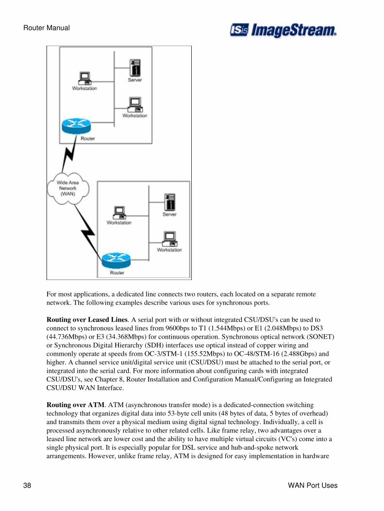
For most applications, a dedicated line connects two routers, each located on a separate remotenetwork. The following examples describe various uses for synchronous ports.
Routing over Leased Lines. A serial port with or without integrated CSU/DSU's can be used toconnect to synchronous leased lines from 9600bps to T1 (1.544Mbps) or E1 (2.048Mbps) to DS3(44.736Mbps) or E3 (34.368Mbps) for continuous operation. Synchronous optical network (SONET)or Synchronous Digital Hierarchy (SDH) interfaces use optical instead of copper wiring andcommonly operate at speeds from OC-3/STM-1 (155.52Mbps) to OC-48/STM-16 (2.488Gbps) andhigher. A channel service unit/digital service unit (CSU/DSU) must be attached to the serial port, orintegrated into the serial card. For more information about configuring cards with integratedCSU/DSU's, see Chapter 8, Router Installation and Configuration Manual/Configuring an IntegratedCSU/DSU WAN Interface.
Routing over ATM. ATM (asynchronous transfer mode) is a dedicated-connection switchingtechnology that organizes digital data into 53-byte cell units (48 bytes of data, 5 bytes of overhead)and transmits them over a physical medium using digital signal technology. Individually, a cell isprocessed asynchronously relative to other related cells. Like frame relay, two advantages over aleased line network are lower cost and the ability to have multiple virtual circuits (VC's) come into asingle physical port. It is especially popular for DSL service and hub-and-spoke networkarrangements. However, unlike frame relay, ATM is designed for easy implementation in hardware
Router Manual
38 WAN Port Uses
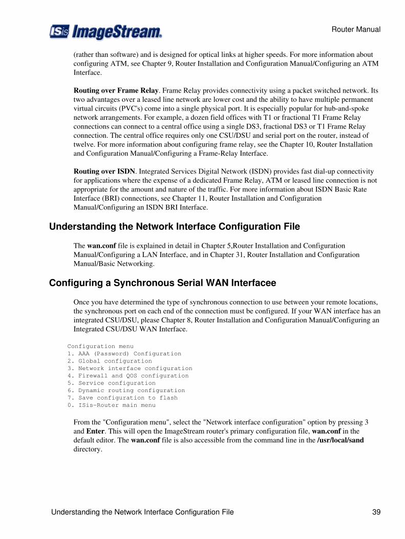
(rather than software) and is designed for optical links at higher speeds. For more information aboutconfiguring ATM, see Chapter 9, Router Installation and Configuration Manual/Configuring an ATMInterface.
Routing over Frame Relay. Frame Relay provides connectivity using a packet switched network. Itstwo advantages over a leased line network are lower cost and the ability to have multiple permanentvirtual circuits (PVC's) come into a single physical port. It is especially popular for hub-and-spokenetwork arrangements. For example, a dozen field offices with T1 or fractional T1 Frame Relayconnections can connect to a central office using a single DS3, fractional DS3 or T1 Frame Relayconnection. The central office requires only one CSU/DSU and serial port on the router, instead oftwelve. For more information about configuring frame relay, see the Chapter 10, Router Installationand Configuration Manual/Configuring a Frame-Relay Interface.
Routing over ISDN. Integrated Services Digital Network (ISDN) provides fast dial-up connectivityfor applications where the expense of a dedicated Frame Relay, ATM or leased line connection is notappropriate for the amount and nature of the traffic. For more information about ISDN Basic RateInterface (BRI) connections, see Chapter 11, Router Installation and ConfigurationManual/Configuring an ISDN BRI Interface.
Understanding the Network Interface Configuration File
The wan.conf file is explained in detail in Chapter 5,Router Installation and ConfigurationManual/Configuring a LAN Interface, and in Chapter 31, Router Installation and ConfigurationManual/Basic Networking.
Configuring a Synchronous Serial WAN Interfacee
Once you have determined the type of synchronous connection to use between your remote locations,the synchronous port on each end of the connection must be configured. If your WAN interface has anintegrated CSU/DSU, please Chapter 8, Router Installation and Configuration Manual/Configuring anIntegrated CSU/DSU WAN Interface.
Configuration menu 1. AAA (Password) Configuration 2. Global configuration 3. Network interface configuration 4. Firewall and QOS configuration 5. Service configuration 6. Dynamic routing configuration 7. Save configuration to flash 0. ISis-Router main menu
From the "Configuration menu", select the "Network interface configuration" option by pressing 3and Enter. This will open the ImageStream router's primary configuration file, wan.conf in thedefault editor. The wan.conf file is also accessible from the command line in the /usr/local/sanddirectory.
Router Manual
Understanding the Network Interface Configuration File 39
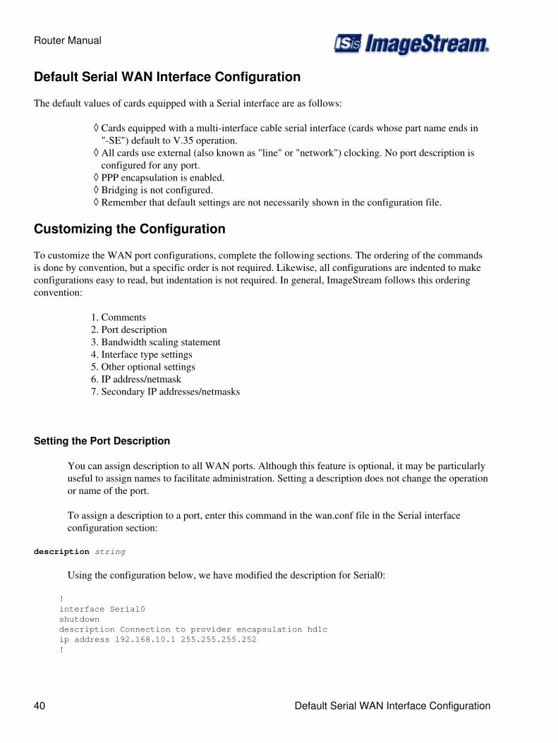
Default Serial WAN Interface Configuration
The default values of cards equipped with a Serial interface are as follows:
Cards equipped with a multi-interface cable serial interface (cards whose part name ends in"-SE") default to V.35 operation.
◊
All cards use external (also known as "line" or "network") clocking. No port description isconfigured for any port.
◊
PPP encapsulation is enabled.◊ Bridging is not configured.◊ Remember that default settings are not necessarily shown in the configuration file.◊
Customizing the Configuration
To customize the WAN port configurations, complete the following sections. The ordering of the commandsis done by convention, but a specific order is not required. Likewise, all configurations are indented to makeconfigurations easy to read, but indentation is not required. In general, ImageStream follows this orderingconvention:
Comments1. Port description2. Bandwidth scaling statement3. Interface type settings4. Other optional settings5. IP address/netmask6. Secondary IP addresses/netmasks7.
Setting the Port Description
You can assign description to all WAN ports. Although this feature is optional, it may be particularlyuseful to assign names to facilitate administration. Setting a description does not change the operationor name of the port.
To assign a description to a port, enter this command in the wan.conf file in the Serial interfaceconfiguration section:
description string
Using the configuration below, we have modified the description for Serial0:
! interface Serial0 shutdown description Connection to provider encapsulation hdlc ip address 192.168.10.1 255.255.255.252 !
Router Manual
40 Default Serial WAN Interface Configuration
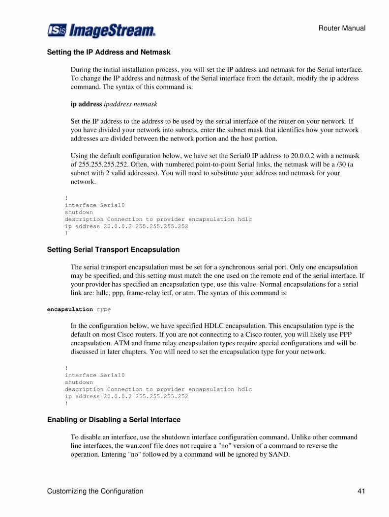
Setting the IP Address and Netmask
During the initial installation process, you will set the IP address and netmask for the Serial interface.To change the IP address and netmask of the Serial interface from the default, modify the ip addresscommand. The syntax of this command is:
ip address ipaddress netmask
Set the IP address to the address to be used by the serial interface of the router on your network. Ifyou have divided your network into subnets, enter the subnet mask that identifies how your networkaddresses are divided between the network portion and the host portion.
Using the default configuration below, we have set the Serial0 IP address to 20.0.0.2 with a netmaskof 255.255.255.252. Often, with numbered point-to-point Serial links, the netmask will be a /30 (asubnet with 2 valid addresses). You will need to substitute your address and netmask for yournetwork.
! interface Serial0 shutdown description Connection to provider encapsulation hdlc ip address 20.0.0.2 255.255.255.252 !
Setting Serial Transport Encapsulation
The serial transport encapsulation must be set for a synchronous serial port. Only one encapsulationmay be specified, and this setting must match the one used on the remote end of the serial interface. Ifyour provider has specified an encapsulation type, use this value. Normal encapsulations for a seriallink are: hdlc, ppp, frame-relay ietf, or atm. The syntax of this command is:
encapsulation type
In the configuration below, we have specified HDLC encapsulation. This encapsulation type is thedefault on most Cisco routers. If you are not connecting to a Cisco router, you will likely use PPPencapsulation. ATM and frame relay encapsulation types require special configurations and will bediscussed in later chapters. You will need to set the encapsulation type for your network.
! interface Serial0 shutdown description Connection to provider encapsulation hdlc ip address 20.0.0.2 255.255.255.252 !
Enabling or Disabling a Serial Interface
To disable an interface, use the shutdown interface configuration command. Unlike other commandline interfaces, the wan.conf file does not require a "no" version of a command to reverse theoperation. Entering "no" followed by a command will be ignored by SAND.
Router Manual
Customizing the Configuration 41
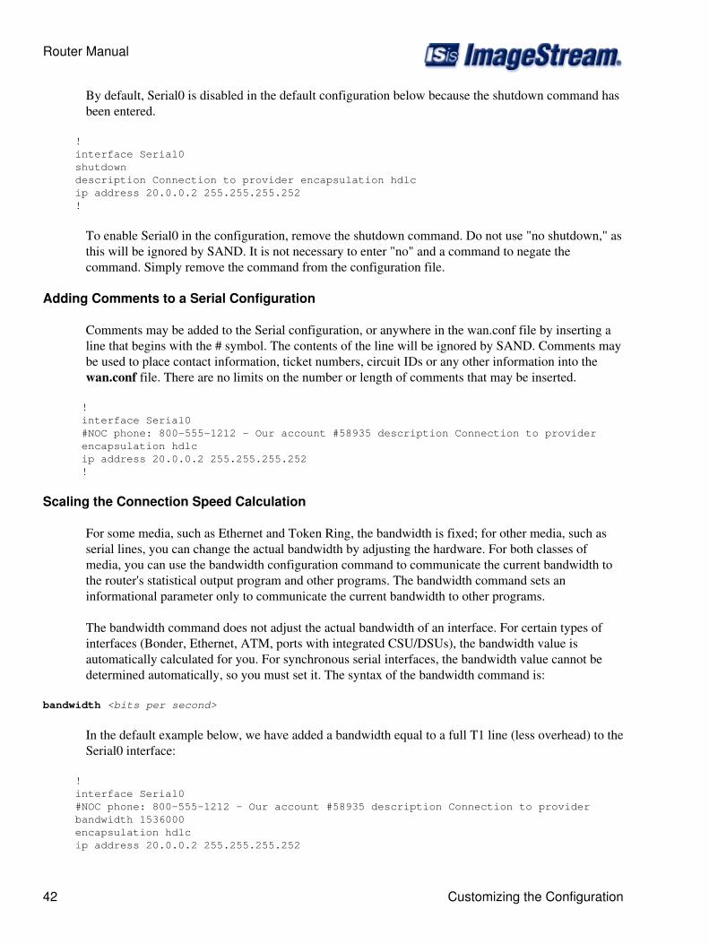
By default, Serial0 is disabled in the default configuration below because the shutdown command hasbeen entered.
! interface Serial0 shutdown description Connection to provider encapsulation hdlc ip address 20.0.0.2 255.255.255.252 !
To enable Serial0 in the configuration, remove the shutdown command. Do not use "no shutdown," asthis will be ignored by SAND. It is not necessary to enter "no" and a command to negate thecommand. Simply remove the command from the configuration file.
Adding Comments to a Serial Configuration
Comments may be added to the Serial configuration, or anywhere in the wan.conf file by inserting aline that begins with the # symbol. The contents of the line will be ignored by SAND. Comments maybe used to place contact information, ticket numbers, circuit IDs or any other information into thewan.conf file. There are no limits on the number or length of comments that may be inserted.
! interface Serial0 #NOC phone: 800-555-1212 - Our account #58935 description Connection to provider encapsulation hdlc ip address 20.0.0.2 255.255.255.252 !
Scaling the Connection Speed Calculation
For some media, such as Ethernet and Token Ring, the bandwidth is fixed; for other media, such asserial lines, you can change the actual bandwidth by adjusting the hardware. For both classes ofmedia, you can use the bandwidth configuration command to communicate the current bandwidth tothe router's statistical output program and other programs. The bandwidth command sets aninformational parameter only to communicate the current bandwidth to other programs.
The bandwidth command does not adjust the actual bandwidth of an interface. For certain types ofinterfaces (Bonder, Ethernet, ATM, ports with integrated CSU/DSUs), the bandwidth value isautomatically calculated for you. For synchronous serial interfaces, the bandwidth value cannot bedetermined automatically, so you must set it. The syntax of the bandwidth command is:
bandwidth <bits per second>
In the default example below, we have added a bandwidth equal to a full T1 line (less overhead) to theSerial0 interface:
! interface Serial0 #NOC phone: 800-555-1212 - Our account #58935 description Connection to provider bandwidth 1536000 encapsulation hdlc ip address 20.0.0.2 255.255.255.252
Router Manual
42 Customizing the Configuration
!
Setting the Serial Interface Type
Most ImageStream synchronous serial interfaces are capable of operating with several differentwiring interfaces. All cards whose part name ends in "-SE" are multi-interface capable. The defaultsetting is for V.35 interfaces, but the multi-interface serial cards can also support RS-232,RS-422/RS-449/X.21 wiring connections when coupled with the correct cable and wiring interfacesetting.
The dctype command is used to set the serial card's daughter card to use a particular wiring interface.In most cases, the synchronous serial connection to the external CSU/DSU will be V.35 or X.21. Thedctype must be set to match the wiring interface used. The syntax of the dctype command is:
dctype type-code
where the type code is either 0 (V.35), 1 (RS-422/RS-449/X.21), or 2 (RS-232). In the defaultexample from above, we have omitted the dctype command since the connection to the CSU/DSU isV.35. Optionally, the command dctype 0 could be added for V.35 operation, although it would havethe same effect as omitting the command.
Adding Secondary Serial Addresses
Although rarely necessary, depending on your network configuration, you may need to configuremore than one address on a Serial device. This task is accomplished by adding the secondary keywordto the ip address line used previously. The secondary keyword is used for all addresses on a Serialdevice other than the primary address. Only one primary address can be configured on a Serial device.Configuring more than one primary address or leaving the secondary keyword off of a secondaryaddress configuration will cause the last primary IP address to be used when the port is configured bySAND.
Using the default configuration below, we have added two secondary IP addresses to Serial0. Youwill need to substitute your address and netmask for your network.
! interface Serial0 #NOC phone: 800-555-1212 - Our account #58935 description Connection to provider bandwidth 1536000 encapsulation hdlc ip address 20.0.0.2 255.255.255.252 ip address 20.0.1.1 255.255.255.0 secondary !
Configuring X.21 Connections
In many non-North American countries, X.21 wiring interfaces are used instead of V.35. X.21 wiring,which provides a balanced signal, differs from other wiring interfaces in that no Data Carrier Detect(DCD) or Data Terminal Ready (DTR) pins are used. Setting dctype 1 sets only the hardware wiring
Router Manual
Customizing the Configuration 43

interface. The router must also be configured to ignore the DCD and DTR signals and use the RequestTo Send (RTS) and Clear To Send (CTS) signals to determine interface status.
For proper X.21 operation, enter the command x21-clockmode. Failing to enter this command willprevent your X.21 connection from becoming active. This command is not necessary for any otherwiring interface, including standard RS-422 and RS-449 wiring interfaces which also share the dctype1 configuration command.
Configuring Additional Serial Devices
If your router is equipped with multiple Serial devices, you can add additional interfaceconfigurations to the wan.conf file. Although the order of the devices in the file does not matter,ImageStream by convention keeps the interfaces in order. Additional Serial devices are configured inthe same manner as Serial0 in our example configuration. Add an additional interface command foreach additional Serial port, separating each section with a ! symbol. The syntax of the interfacecommand is:
interface DeviceName
In the default example below, we have added a second Serial port at Serial1 (note the use of thedctype command and x21-clockmode command for X.21 operation) and a third Serial port at Serial2.
! interface Serial0 #NOC phone: 800-555-1212 - Our account #58935 description Connection to provider bandwidth 1536000 encapsulation hdlc ip address 20.0.0.2 255.255.255.252 ip address 20.0.1.1 255.255.255.0 secondary ! interface Serial1 description Connection to London office bandwidth 2048000 encapsulation ppp dctype 1 x21-clockmode ip address 25.0.0.1 255.255.255.252 ! interface Serial2 #HSSI card description fractional DS3 to NYC bandwidth 10000000 encapsulation hdlc ip address 30.0.0.1 255.255.255.252 !
Note: You must save the settings to the router's non-volatile flash memory! If the router is rebootedbefore saving, your changes will be lost! See Chapter 26, Router Installation and ConfigurationManual/Backup/Restore Menu: Managing Configurations for more information.
Configuring an Integrated CSU/DSU WAN Interface
This chapter describes how to configure the ImageStream router serial WAN interfaces withintegrated CSU/DSUs and includes the following topics:
Router Manual
44 Customizing the Configuration
WAN Port Uses◊ Understanding the Network Interface Configuration File◊ Configuring an Integrated CSU/DSU WAN Interface◊ Default Integrated CSU/DSU WAN Interface Configuration◊ Customizing the Configuration◊ Setting Integrated CSU/DSU Parameters◊ Configuring Additional Serial Devices◊
Before configuring the WAN interface, you must make the appropriate cabling connection for yourneeds. Refer to the hardware installation guide for your ImageStream product for information onmaking the WAN connection. See the Command Reference for more detailed command descriptionsand instructions.
WAN Port Uses
WAN ports uses is explained in Chapter 7, Router Installation and Configuration Manual/Configuringa Synchronous Serial WAN Interface and in Chapter 31, Router Installation and ConfigurationManual/Basic Networking.
Understanding the Network Interface Configuration File
The wan.conf file is explained in detail in Chapter 5, Router Installation and ConfigurationManual/Configuring a LAN Interface, and in Chapter 31, Router Installation and ConfigurationManual/Basic Networking.
Configuring an Integrated CSU/DSU WAN Interface
Once you have determined the type of synchronous connection to use between your remote locations,the synchronous port on each end of the connection must be configured. If your WAN interface doesnot have an integrated CSU/DSU, please see Chapter 7, Router Installation and ConfigurationManual/Configuring a Synchronous Serial WAN Interface.
Configuration menu 1. AAA (Password) Configuration 2. Global configuration 3. Network interface configuration 4. Firewall and QOS configuration 5. Service configuration 6. Dynamic routing configuration 7. Save configuration to flash 0. ISis-Router main menu
From the "Configuration menu", select the "Network interface configuration" option by pressing 3and Enter. This will open the ImageStream router's primary configuration file, wan.conf in thedefault editor. The wan.conf file is also accessible from the command line in the /usr/local/sanddirectory.
Router Manual
Configuring an Integrated CSU/DSU WAN Interface 45
Default Integrated CSU/DSU WAN Card Configuration
The default values of cards equipped with an integrated CSU/DSU interface are as follows:
Integrated T1 and E1 CSU/DSU's default to the following values:
ESF framing (CCS for E1 circuits)◊ B8ZS encoding (HDB3 for E1 circuits)◊ No line buildout◊ All timeslots configured, all at 64K speeds◊ Equalizer gain limit (EGL) off◊ Normal data encoding◊ Structured mode (E1 only)◊ CRC4 checksums disabled (E1 only)◊
Integrated DS3 and E3 CSU/DSUs default to the following values:
C-bit framing◊ No line buildout◊ All timeslots configured◊ Equalizer gain limit (EGL) off◊
All cards use external (also known as "line" or "network") clocking. No port description is configuredfor any port.PPP encapsulation is enabled.Bridging is not configured.
NOTE: Remember that default settings are not necessarily shown in the configuration file.
Customizing the Configuration
To customize the WAN port configurations, complete the following sections. The ordering of thecommands is done by convention, but a specific order is not required. Likewise, all configurations areindented to make configurations easy to read, but indentation is not required. In general, ImageStreamfollows this ordering convention:
Comments1. Port description2. Bandwidth scaling statement3. CSU/DSU settings4. Other optional settings5. IP address/netmask6. Secondary IP addresses/netmasks7.
Setting the Port Description
You can assign description to all WAN ports. Although this feature is optional, it may be particularlyuseful to assign names to facilitate administration. Setting a description does not change the operation
Router Manual
46 Default Integrated CSU/DSU WAN Card Configuration
or name of the port.
To assign a description to a port, enter this command in the wan.conf file in the Serial interfaceconfiguration section:
description string
Using the router's default configuration below, we have modified the description for Serial0:
! interface Serial0 shutdown description Connection to provider encapsulation hdlc ip address 192.168.10.1 255.255.255.252 !
Setting the IP Address and Netmask
During the initial installation process, you will set the IP address and netmask for the Serial interface.To change the IP address and netmask of the Serial interface from the default, modify the ip addresscommand. The syntax of this command is:
ip address ipaddress netmask
Set the IP address to the address to be used by the serial interface of the router on your network. Ifyou have divided your network into subnets, enter the subnet mask that identifies how your networkaddresses are divided between the network portion and the host portion.
Using the default configuration below, we have set the Serial0 IP address to 20.0.0.2 with a netmaskof 255.255.255.252. Often, with numbered point-to-point Serial links, the netmask will be a /30 (asubnet with 2 valid addresses). You will need to substitute your address and netmask for yournetwork.
! interface Serial0 shutdown description Connection to provider encapsulation hdlc ip address 20.0.0.2 255.255.255.252 !
Setting Serial Transport Encapsulation
The serial transport encapsulation must be set for an integrated CSU/DSU serial port. Only oneencapsulation may be specified, and this setting must match the one used on the remote end of theserial interface. If your provider has specified an encapsulation type, use this value. Normalencapsulations for a serial link are: hdlc, ppp, frame-relay ietf, or atm. The syntax of this command is:
encapsulation type
Router Manual
Customizing the Configuration 47
In the default configuration below, we have specified HDLC encapsulation. This encapsulation type isthe default on most Cisco routers. If you are not connecting to a Cisco router, you will likely use PPPencapsulation. ATM and frame relay encapsulation types require special configurations and will bediscussed in later chapters. You will need to set the encapsulation type for your network.
! interface Serial0 shutdown description Connection to provider encapsulation hdlc ip address 20.0.0.2 255.255.255.252 !
Enabling or Disabling a Serial Interface
To disable an interface, use the shutdown interface configuration command. Unlike other commandline interfaces, the wan.conf file does not require a "no" version of a command to reverse theoperation. Entering "no" followed by a command will be ignored by SAND.
By default, Serial0 is disabled in the default configuration below because the shutdown command hasbeen entered.
! interface Serial0 shutdown description Connection to provider encapsulation hdlc ip address 20.0.0.2 255.255.255.252 !
To enable Serial0 in the configuration, remove the shutdown command. Do not use "no shutdown", asthis will be ignored by SAND. It is not necessary to enter "no" and a command to negate thecommand. Simply remove the command from the configuration file.
Adding Comments to a Serial Configuration
Comments may be added to the Serial configuration, or anywhere in the wan.conf file by inserting aline that begins with the # symbol. The contents of the line will be ignored by SAND. Comments maybe used to place contact information, ticket numbers, circuit IDs or any other information into thewan.conf file. There are no limits on the number or length of comments that may be inserted.
! interface Serial0 #NOC phone: 800-555-1212 - Our account #58935 description Connection to provider encapsulation hdlc ip address 20.0.0.2 255.255.255.252 !
Scaling the connection speed calculation
For some media, such as Ethernet and Token Ring, the bandwidth is fixed; for other media, such asserial lines, you can change the actual bandwidth by adjusting the hardware. For both classes ofmedia, you can use the bandwidth configuration command to communicate the current bandwidth to
Router Manual
48 Customizing the Configuration
the router's statistical output program and other programs. The bandwidth command sets aninformational parameter only to communicate the current bandwidth to other programs.
The bandwidth command does not adjust the actual bandwidth of an interface. Ports with integratedCSU/DSU's automatically calculate the bandwidth value based on the number of timeslots configured.In our example above, the router will automatically calculate the bandwidth of 1536000 (full T1 lessoverhead). The syntax of the bandwidth command is:
bandwidth bits per second
In the default example from below, we have added a bandwidth equal to a full T1 line (less overhead)to the Serial0 interface. This value is calculated automatically, so this command is optional:
! interface Serial0 #NOC phone: 800-555-1212 - Our account #58935 description Connection to provider bandwidth 1536000 encapsulation hdlc ip address 20.0.0.2 255.255.255.252 !
Setting Integrated T1 CSU/DSU Parameters
The service-module command is used to configure the serial card's integrated T1 CSU/DSU. In mostcases, the defaults provided on the integrated CSU/DSU will match the network configuration. Checkwith your line provider to determine if your line settings differ from the default CSU/DSUconfiguration. The configurations in the interface configuration must match the settings for your lineor your serial interface will not function correctly.
Configuring the T1 Line Clocking Source
Unlike asynchronous devices, a synchronous data interface must a clock source to use for networktiming. One and only one clock source should be configured on a line. In most cases, your lineprovider will provide a clock source for the T1 line. The T1 CSU/DSU can also be configured toprovide a clock source. The syntax of this command is:
service-module t1 clock source { line | internal }
The line or internal keyword specifies the type of clocking to use on this interface. Line (also knownas "network" or "external") timing is the default value. Using the internal keyword will enable theCSU/DSU's internal clock and will instruct the CSU/DSU to place this clock source on the line.Configuring more than one clock source, or having no clock source, can cause a line to havesynchronization problems resulting in framing errors and data loss. Check with your line providerbefore enabling internal clocking to ensure that this setting is needed.
We have specified the default value in the default configuration as seen below.
! interface Serial0 #NOC phone: 800-555-1212 - Our account #58935 description Connection to provider bandwidth 1536000
Router Manual
Scaling the connection speed calculation 49
encapsulation hdlc service-module t1 clock source line ip address 20.0.0.2 255.255.255.252 !
Configuring T1 Time Slots and Channel Speeds
To configure the number of time slots allocated to the Serial interface, include the time slots statementin the interface configuration. The syntax of this command is:
service-module t1 timeslots { range | all } [speed { 56 | 64 }]
where the range is a value of 1 to 24 for T1. The speed keyword configures the byte encoding of theT1 line. By default, T1 lines use a byte encoding of 8 bits per byte (64 kbps channels). You canconfigure an alternative byte encoding of 7 bits per byte (56 kbps channels).
You can designate any combination of time slots for usage. The default is to use all time slots.
To use time slots 1 through 10, designate time-slot-number as follows:
service-module t1 timeslots 1-10
To use time slots 1 through 5, time slot 10, and time slot 24, designate the timeslot range as follows:
service-module t1 timeslots 1-5,10,24;
To use the first four odd-numbered time slots, designate the timeslot range as follows:
service-module t1 timeslots 1,3,5,7
NOTE: Spaces are not allowed between timeslot numbers.
In the default configuration, we have inserted the default value "all":
! interface Serial0 #NOC phone: 800-555-1212 - Our account #58935 description Connection to provider bandwidth 1536000 encapsulation hdlc service-module t1 clock source line service-module t1 timeslots all speed 64 ip address 20.0.0.2 255.255.255.252 !
Configuring T1 Data Inversion
By default, data inversion is disabled. To enable data inversion at the HDLC level, include theservice-module t1 data coding { normal | inverted } statement in the interface configuration. Whenyou enable data inversion, all data bits in the data stream are transmitted as inverted; that is, zeroes aretransmitted as ones and ones as zeroes. Data inversion is normally used only in AMI mode toguarantee ones density in the transmitted stream.
Router Manual
50 Setting Integrated T1 CSU/DSU Parameters
Configuring T1 Line Buildout
A T1 interface has 4 possible settings for T1 line buildout. The line buildout setting is used to set thesignal attenuation factor due to the impedance of copper cabling. The line buildout setting is used onwhen the connection between the integrated CSU/DSU and the line provider demarcation point isgreater than 225 feet. By default, the T1 interfaces use the shortest setting (none). The commandsyntax is:
service-module t1 lbo value
where the value is either -22.5 db, -15 db, -7.5 db, or none. If you are unsure of which setting to use,leave the builtout at the shortest setting. In the default example from above, we have omitted theservice-module t1 lbo command since the connection to the demarc is less than 225 feet. Optionally,the command service-module t1 lbo none could be added, although it would have the same effect asomitting the command.
Configuring the T1 Equalizer Gain Limiter
The T1 interface has an equalizer gain limiter. This setting is used to turn on the receiver gain limiterto overcome impedance of copper cabling. The gain limiter should be turned on when the connectionbetween the integrated CSU/DSU and the line provider demarcation point is greater than 225 feet. Bydefault, the T1 interfaces do not enable the gain limiter. To enable the equalizer gain limiter, add thecommand servicemodule t1 egl to the interface configuration. This command is normally used inconjunction with the line buildout command.
Configuring T1 Framing
By default, T1 interfaces use an extended super frame (ESF) framing format. To explicitly configureESF framing, include the framing statement in the interface configuration for the serial device:
service-module t1 framing esf
You can configure SF (super frame, also known as "D4") format as an alternative. To have theinterface use the SF framing format, include the framing statement in the interface configuration,specifying the sf option. In the default configuration below, we have specified the default ESFframing:
! interface Serial0 #NOC phone: 800-555-1212 - Our account #58935 description Connection to provider bandwidth 1536000 encapsulation hdlc service-module t1 clock source line service-module t1 timeslots all speed 64 service-module t1 framing esf ip address 20.0.0.2 255.255.255.252 !
Router Manual
Setting Integrated T1 CSU/DSU Parameters 51

Configuring T1 Line Encoding
By default, T1 interfaces use a B8ZS line encoding. To explicitly configure B8ZS line encoding,include the linecode statement in the interface configuration for the serial device:
service-module t1 linecode b8zs
You can configure AMI line encoding as an alternative. To have the interface use the AMI framingformat, include the framing statement in the interface configuration, specifying the ami option. In thedefault configuration below, we have specified the default B8ZS line encoding:
! interface Serial0 #NOC phone: 800-555-1212 - Our account #58935 description Connection to provider bandwidth 1536000 encapsulation hdlc service-module t1 clock source line service-module t1 timeslots all speed 64 service-module t1 framing esf service-module t1 linecode b8zs ip address 20.0.0.2 255.255.255.252 !
Setting Integrated E1 CSU/DSU Parameters
The service-module command is used to configure the serial card's integrated E1 CSU/DSU. In mostcases, the defaults provided on the integrated CSU/DSU will match the network configuration. Checkwith your line provider to determine if your line settings differ from the default CSU/DSUconfiguration. The configurations in the interface configuration must match the settings for your lineor your serial interface will not function correctly.
Configuring the E1 Line Clocking Source
Unlike asynchronous devices, a synchronous data interface must a clock source to use for networktiming. One and only one clock source should be configured on a line. In most cases, your lineprovider will provide a clock source for the E1 line. The E1 CSU/DSU can also be configured to4provide a clock source. The syntax of this command is:
service-module e1 clock source { line | internal }
The line or internal keyword specifies the type of clocking to use on this interface. Line (also knownas "network" or "external") timing is the default value. Using the internal keyword will enable theCSU/DSU's internal clock and will instruct the CSU/DSU to place this clock source on the line.Configuring more than one clock source, or having no clock source, can cause a line to havesynchronization problems resulting in framing errors and data loss. Check with your line providerbefore enabling internal clocking to ensure that this setting is needed. We have specified the defaultvalue in the default configuration below:
! interface Serial0 #NOC phone: 800-555-1212 - Our account #58935 description Connection to provider bandwidth 1536000
Router Manual
52 Setting Integrated T1 CSU/DSU Parameters
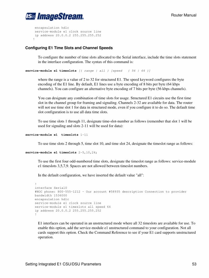
encapsulation hdlc service-module e1 clock source line ip address 20.0.0.2 255.255.255.252 !
Configuring E1 Time Slots and Channel Speeds
To configure the number of time slots allocated to the Serial interface, include the time slots statementin the interface configuration. The syntax of this command is:
service-module e1 timeslots [{ range | all } [speed { 56 | 64 }]
where the range is a value of 2 to 32 for structured E1. The speed keyword configures the byteencoding of the E1 line. By default, E1 lines use a byte encoding of 8 bits per byte (64 kbpschannels). You can configure an alternative byte encoding of 7 bits per byte (56 kbps channels).
You can designate any combination of time slots for usage. Structured E1 circuits use the first timeslot in the channel group for framing and signaling. Channels 2-32 are available for data. The routerwill not use time slot 1 for data in structured mode, even if you configure it to do so. The default timeslot configuration is to use all data time slots.
To use time slots 1 through 11, designate time-slot-number as follows (remember that slot 1 will beused for signaling and slots 2-11 will be used for data):
service-module e1 timeslots 1-11
To use time slots 2 through 5, time slot 10, and time slot 24, designate the timeslot range as follows:
service-module e1 timeslots 2-5,10,24;
To use the first four odd-numbered time slots, designate the timeslot range as follows: service-modulee1 timeslots 3,5,7,9. Spaces are not allowed between timeslot numbers.
In the default configuration, we have inserted the default value "all":
! interface Serial0 #NOC phone: 800-555-1212 - Our account #58935 description Connection to provider bandwidth 1536000 encapsulation hdlc service-module e1 clock source line service-module e1 timeslots all speed 64 ip address 20.0.0.2 255.255.255.252 !
E1 interfaces can be operated in an unstructured mode where all 32 timeslots are available for use. Toenable this option, add the service-module e1 unstructured command to your configuration. Not allcards support this option. Check the Command Reference to see if your E1 card supports unstructuredoperation.
Router Manual
Setting Integrated E1 CSU/DSU Parameters 53
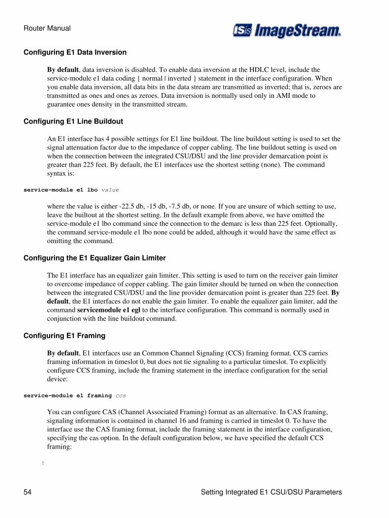
Configuring E1 Data Inversion
By default, data inversion is disabled. To enable data inversion at the HDLC level, include theservice-module e1 data coding { normal | inverted } statement in the interface configuration. Whenyou enable data inversion, all data bits in the data stream are transmitted as inverted; that is, zeroes aretransmitted as ones and ones as zeroes. Data inversion is normally used only in AMI mode toguarantee ones density in the transmitted stream.
Configuring E1 Line Buildout
An E1 interface has 4 possible settings for E1 line buildout. The line buildout setting is used to set thesignal attenuation factor due to the impedance of copper cabling. The line buildout setting is used onwhen the connection between the integrated CSU/DSU and the line provider demarcation point isgreater than 225 feet. By default, the E1 interfaces use the shortest setting (none). The commandsyntax is:
service-module e1 lbo value
where the value is either -22.5 db, -15 db, -7.5 db, or none. If you are unsure of which setting to use,leave the builtout at the shortest setting. In the default example from above, we have omitted theservice-module e1 lbo command since the connection to the demarc is less than 225 feet. Optionally,the command service-module e1 lbo none could be added, although it would have the same effect asomitting the command.
Configuring the E1 Equalizer Gain Limiter
The E1 interface has an equalizer gain limiter. This setting is used to turn on the receiver gain limiterto overcome impedance of copper cabling. The gain limiter should be turned on when the connectionbetween the integrated CSU/DSU and the line provider demarcation point is greater than 225 feet. Bydefault, the E1 interfaces do not enable the gain limiter. To enable the equalizer gain limiter, add thecommand servicemodule e1 egl to the interface configuration. This command is normally used inconjunction with the line buildout command.
Configuring E1 Framing
By default, E1 interfaces use an Common Channel Signaling (CCS) framing format. CCS carriesframing information in timeslot 0, but does not tie signaling to a particular timeslot. To explicitlyconfigure CCS framing, include the framing statement in the interface configuration for the serialdevice:
service-module e1 framing ccs
You can configure CAS (Channel Associated Framing) format as an alternative. In CAS framing,signaling information is contained in channel 16 and framing is carried in timeslot 0. To have theinterface use the CAS framing format, include the framing statement in the interface configuration,specifying the cas option. In the default configuration below, we have specified the default CCSframing:
!
Router Manual
54 Setting Integrated E1 CSU/DSU Parameters
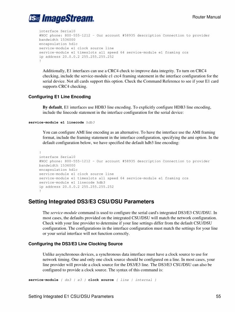
interface Serial0 #NOC phone: 800-555-1212 - Our account #58935 description Connection to provider bandwidth 1536000 encapsulation hdlc service-module e1 clock source line service-module e1 timeslots all speed 64 service-module e1 framing ccs ip address 20.0.0.2 255.255.255.252 !
Additionally, E1 interfaces can use a CRC4 check to improve data integrity. To turn on CRC4checking, include the service-module e1 crc4 framing statement in the interface configuration for theserial device. Not all cards support this option. Check the Command Reference to see if your E1 cardsupports CRC4 checking.
Configuring E1 Line Encoding
By default, E1 interfaces use HDB3 line encoding. To explicitly configure HDB3 line encoding,include the linecode statement in the interface configuration for the serial device:
service-module e1 linecode hdb3
You can configure AMI line encoding as an alternative. To have the interface use the AMI framingformat, include the framing statement in the interface configuration, specifying the ami option. In thedefault configuration below, we have specified the default hdb3 line encoding:
! interface Serial0 #NOC phone: 800-555-1212 - Our account #58935 description Connection to provider bandwidth 1536000 encapsulation hdlc service-module e1 clock source line service-module e1 timeslots all speed 64 service-module e1 framing ccs service-module e1 linecode hdb3 ip address 20.0.0.2 255.255.255.252 !
Setting Integrated DS3/E3 CSU/DSU Parameters
The service-module command is used to configure the serial card's integrated DS3/E3 CSU/DSU. Inmost cases, the defaults provided on the integrated CSU/DSU will match the network configuration.Check with your line provider to determine if your line settings differ from the default CSU/DSUconfiguration. The configurations in the interface configuration must match the settings for your lineor your serial interface will not function correctly.
Configuring the DS3/E3 Line Clocking Source
Unlike asynchronous devices, a synchronous data interface must have a clock source to use fornetwork timing. One and only one clock source should be configured on a line. In most cases, yourline provider will provide a clock source for the DS3/E3 line. The DS3/E3 CSU/DSU can also beconfigured to provide a clock source. The syntax of this command is:
service-module { ds3 | e3 } clock source { line | internal }
Router Manual
Setting Integrated E1 CSU/DSU Parameters 55
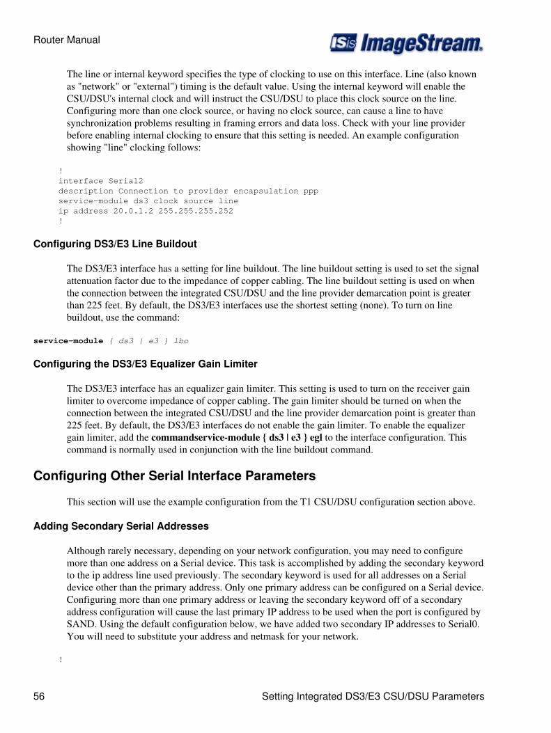
The line or internal keyword specifies the type of clocking to use on this interface. Line (also knownas "network" or "external") timing is the default value. Using the internal keyword will enable theCSU/DSU's internal clock and will instruct the CSU/DSU to place this clock source on the line.Configuring more than one clock source, or having no clock source, can cause a line to havesynchronization problems resulting in framing errors and data loss. Check with your line providerbefore enabling internal clocking to ensure that this setting is needed. An example configurationshowing "line" clocking follows:
! interface Serial2 description Connection to provider encapsulation ppp service-module ds3 clock source line ip address 20.0.1.2 255.255.255.252 !
Configuring DS3/E3 Line Buildout
The DS3/E3 interface has a setting for line buildout. The line buildout setting is used to set the signalattenuation factor due to the impedance of copper cabling. The line buildout setting is used on whenthe connection between the integrated CSU/DSU and the line provider demarcation point is greaterthan 225 feet. By default, the DS3/E3 interfaces use the shortest setting (none). To turn on linebuildout, use the command:
service-module { ds3 | e3 } lbo
Configuring the DS3/E3 Equalizer Gain Limiter
The DS3/E3 interface has an equalizer gain limiter. This setting is used to turn on the receiver gainlimiter to overcome impedance of copper cabling. The gain limiter should be turned on when theconnection between the integrated CSU/DSU and the line provider demarcation point is greater than225 feet. By default, the DS3/E3 interfaces do not enable the gain limiter. To enable the equalizergain limiter, add the commandservice-module { ds3 | e3 } egl to the interface configuration. Thiscommand is normally used in conjunction with the line buildout command.
Configuring Other Serial Interface Parameters
This section will use the example configuration from the T1 CSU/DSU configuration section above.
Adding Secondary Serial Addresses
Although rarely necessary, depending on your network configuration, you may need to configuremore than one address on a Serial device. This task is accomplished by adding the secondary keywordto the ip address line used previously. The secondary keyword is used for all addresses on a Serialdevice other than the primary address. Only one primary address can be configured on a Serial device.Configuring more than one primary address or leaving the secondary keyword off of a secondaryaddress configuration will cause the last primary IP address to be used when the port is configured bySAND. Using the default configuration below, we have added two secondary IP addresses to Serial0.You will need to substitute your address and netmask for your network.
!
Router Manual
56 Setting Integrated DS3/E3 CSU/DSU Parameters
interface Serial0 #NOC phone: 800-555-1212 - Our account #58935 description Connection to provider bandwidth 1536000 encapsulation hdlc service-module t1 clock source line service-module t1 timeslots all speed 64 service-module t1 framing esf service-module t1 linecode b8zs ip address 20.0.0.2 255.255.255.252 ip address 20.0.1.1 255.255.255.0 secondary !
Configuring Additional Serial Devices
If your router is equipped with multiple Serial devices, you can add additional interfaceconfigurations to the wan.conf file. Although the order of the devices in the file does not matter,ImageStream by convention keeps the interfaces in order.
Additional Serial devices are configured in the same manner as Serial0 in our example configuration.Add an additional interface command for each additional Serial port, separating each section with a !symbol. The syntax of the interface command is:
interface DeviceName
In the default example below, we have added a second Serial port at Serial1 (note the use of theinternal clocking command and alternate framing and encoding settings) and a third Serial port atSerial2.
! interface Serial0 #NOC phone: 800-555-1212 - Our account #58935 description Connection to provider bandwidth 1536000 encapsulation hdlc service-module t1 clock source line service-module t1 timeslots all speed 64 service-module t1 framing esf service-module t1 linecode b8zs ip address 20.0.0.2 255.255.255.252 ip address 20.0.1.1 255.255.255.0 secondary ! interface Serial1 description Connection to London office encapsulation ppp service-module t1 clocking internal service-module t1 framing sf service-module t1 linecode ami ip address 25.0.0.1 255.255.255.252 ! interface Serial2 #HSSI card description fractional DS3 to NYC bandwidth 10000000 encapsulation hdlc ip address 30.0.0.1 255.255.255.252 !
Router Manual
Configuring Other Serial Interface Parameters 57
Note: You must save the settings to the router's non-volatile flash memory! If the router is rebootedbefore saving, your changes will be lost! See Chapter 26, "Backup/Restore Menu: ManagingConfigurations" for more information.
Configuring an ATM Interface
This chapter describes how to configure the ImageStream router ATM WAN interfaces and includesthe following topics:
WAN Port Uses◊ Understanding the Network Interface Configuration File◊ Configuring an ATM Master Interface◊ Default ATM Interface Configuration◊ Customizing the Configuration◊ Setting ATM Master Interface Parameters◊ Configuring an ATM Subinterface◊
Before configuring the WAN interface, you must make the appropriate cabling connection for yourneeds. Refer to the hardware installation guide for your ImageStream product for information onmaking the WAN connection. See the Technical Notes section on the ImageStream Web site or theCommand Reference for more detailed command descriptions, examples and instructions.
WAN Port Uses
WAN ports uses has been explained in Chapter 7, Router Installation and ConfigurationManual/Configuring a Synchronous Serial WAN Interface and in Chapter 31 Router Installation andConfiguration Manual/Basic Networking.
Understanding the Network Interface Configuration File
The wan.conf file is explained in detail in Chapter 5, Router Installation and ConfigurationManual/Configuring a LAN Interface, and in Chapter 31,Router Installation and ConfigurationManual/Basic Networking.
Configuring an ATM Master Interface
Asynchronous Transfer Mode (ATM) is a network protocol designed to facilitate the simultaneoustransfer of various types of traffic streams (voice, data, video) on public and private networks over thesame physical connection. By always using 53-byte cells, ATM simplifies the design of hardware,enabling it to quickly determine the destination address of each cell. This allows simple switching ofnetwork traffic at much higher speeds than are easily accomplished using protocols with variable sizesof transfer units, such as Frame Relay and TCP/IP.
ATM relies on the concepts of virtual paths and virtual circuits. A virtual path, represented by aspecific virtual path identifier (VPI), establishes a route between two devices in a network. Each VPIcan contain multiple virtual circuits, each represented by a virtual circuit identifier (VCI).
Router Manual
58 Configuring an ATM Interface
On an ImageStream router, each VPI/VCI pair is defined on the physical ATM interface as asubinterface. A subinterface is a logical (virtual) interface and is a part of a physical interface, such asan ATM DS3. Each physical ATM interface can be logically divided into as many as 64,000 differentlogical subinterfaces, depending on the card used.
The ATM port on each end of the connection must be configured prior to use. If your WAN interfacedoes not support ATM encapsulations, please See Chapter 7, Router Installation and ConfigurationManual/Configuring a Synchronous Serial WAN Interface or Chapter 8, Router Installation andConfiguration Manual/Configuring an Integrated CSU/DSU WAN Interface. Attempting toconfiguring non-ATM encapsulations on an ATM card will result in errors.
Configuration menu 1. AAA (Password) Configuration 2. Global configuration 3. Network interface configuration 4. Firewall and QOS configuration 5. Service configuration 6. Dynamic routing configuration 7. Save configuration to flash 0. ISis-Router main menu
From the :Configuration menu", select menu option 2, Network interface configuration, and pressEnter. This will open the ImageStream router's primary configuration file, wan.conf in the defaulteditor. The wan.conf file is also accessible from the command line in the /usr/local/sand directory.
Default ATM WAN Card Configuration
The default values of cards equipped with an ATM interface are as follows:
ATM WAN interfaces default to the following values:
C-bit framing (for DS3)◊ PLCP mode◊ DS3 transport◊ No line buildout◊ ATM cell scrambling configured◊ Equalizer gain limit (EGL) off◊ SONET interface mode (for OC-3, OC-12)◊
All cards use external (also known as "line" or "network") clocking. No port description is configuredfor any port.Classical IP over ATM encapsulation is enabled. Bridging is not configured.
Remember that default settings are not necessarily shown in the configuration file.
Customizing the Configuration
To customize the WAN port configurations, complete the following sections. The ordering of thecommands is done by convention, but a specific order is not required. Likewise, all configurations areindented to make configurations easy to read, but indentation is not required. In general, ImageStreamfollows this ordering convention:
Router Manual
Configuring an ATM Master Interface 59
Comments1. Port description2. Bandwidth scaling statement3. ATM interface settings4. Other optional settings5. IP address/netmask6. Secondary IP addresses/netmasks7. Subinterface configurations8.
Setting the Port Description
You can assign description to all WAN ports. Although this feature is optional, it may be particularlyuseful to assign names to facilitate administration. Setting a description does not change the operationor name of the port.
To assign a description to a port, enter this command in the wan.conf file in the Serial interfaceconfiguration section:
description string
Using the router's default configuration below, we have modified the description for Serial0:
! interface Serial0 shutdown description ATM connection to branch offices encapsulation hdlc ip address 192.168.10.1 255.255.255.252 !
Setting the IP Address and Netmask
The ATM master interface does not contain IP addressing information. All IP addresses are containedin the subinterfaces (logical interfaces) configured on the master interface. Using the defaultconfiguration below, we have deleted the ip address line.
! interface Serial0 shutdown description ATM connection to branch offices encapsulation hdlc !
Setting Serial Transport Encapsulation
The serial transport encapsulation must be set to an ATM encapsulation for an ATM interface. Noother encapsulation types may be specified.The syntax of this command is:
encapsulation atm:
In the default configuration below, we have changed the encapsulation to Classical IP overATM. This encapsulation type corresponds to "encapsulation aal5" on a Cisco router.Alternately, you may specify an encapsulation type of aal5snap for SNAP encapsulated ATM
Router Manual
60 Customizing the Configuration
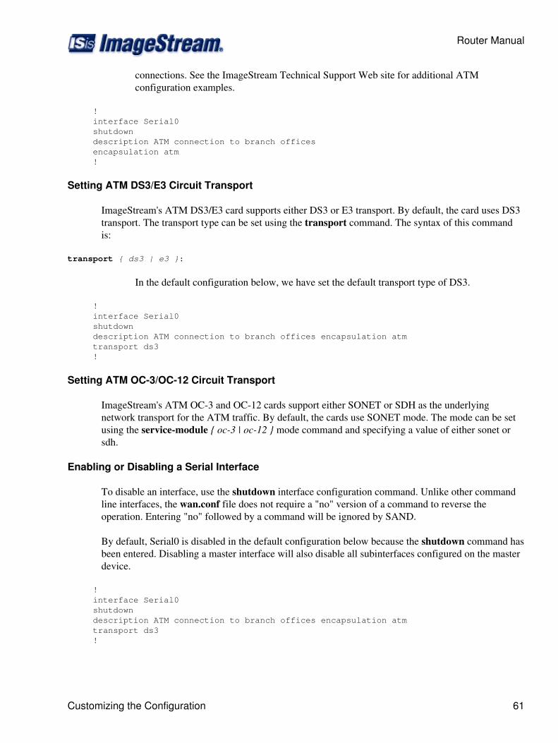
connections. See the ImageStream Technical Support Web site for additional ATMconfiguration examples.
! interface Serial0 shutdown description ATM connection to branch offices encapsulation atm !
Setting ATM DS3/E3 Circuit Transport
ImageStream's ATM DS3/E3 card supports either DS3 or E3 transport. By default, the card uses DS3transport. The transport type can be set using the transport command. The syntax of this commandis:
transport { ds3 | e3 }:
In the default configuration below, we have set the default transport type of DS3.
! interface Serial0 shutdown description ATM connection to branch offices encapsulation atm transport ds3 !
Setting ATM OC-3/OC-12 Circuit Transport
ImageStream's ATM OC-3 and OC-12 cards support either SONET or SDH as the underlyingnetwork transport for the ATM traffic. By default, the cards use SONET mode. The mode can be setusing the service-module { oc-3 | oc-12 } mode command and specifying a value of either sonet orsdh.
Enabling or Disabling a Serial Interface
To disable an interface, use the shutdown interface configuration command. Unlike other commandline interfaces, the wan.conf file does not require a "no" version of a command to reverse theoperation. Entering "no" followed by a command will be ignored by SAND.
By default, Serial0 is disabled in the default configuration below because the shutdown command hasbeen entered. Disabling a master interface will also disable all subinterfaces configured on the masterdevice.
! interface Serial0 shutdown description ATM connection to branch offices encapsulation atm transport ds3 !
Router Manual
Customizing the Configuration 61
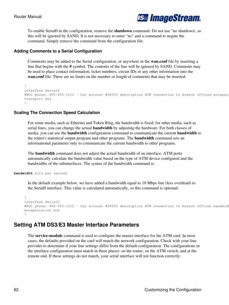
To enable Serial0 in the configuration, remove the shutdown command. Do not use "no shutdown', asthis will be ignored by SAND. It is not necessary to enter "no" and a command to negate thecommand. Simply remove the command from the configuration file.
Adding Comments to a Serial Configuration
Comments may be added to the Serial configuration, or anywhere in the wan.conf file by inserting aline that begins with the # symbol. The contents of the line will be ignored by SAND. Comments maybe used to place contact information, ticket numbers, circuit IDs or any other information into thewan.conf file. There are no limits on the number or length of comments that may be inserted.
! interface Serial0 #NOC phone: 800-555-1212 - Our account #58935 description ATM connection to branch offices encapsulation atm transport ds3 !
Scaling The Connection Speed Calculation
For some media, such as Ethernet and Token Ring, the bandwidth is fixed; for other media, such asserial lines, you can change the actual bandwidth by adjusting the hardware. For both classes ofmedia, you can use the bandwidth configuration command to communicate the current bandwidth tothe router's statistical output program and other programs. The bandwidth command sets aninformational parameter only to communicate the current bandwidth to other programs.
The bandwidth command does not adjust the actual bandwidth of an interface. ATM portsautomatically calculate the bandwidth value based on the type of ATM device configured and thebandwidths of the subinterfaces. The syntax of the bandwidth command is:
bandwidth bits per second:
In the default example below, we have added a bandwidth equal to 10 Mbps line (less overhead) tothe Serial0 interface. This value is calculated automatically, so this command is optional:
! interface Serial0 #NOC phone: 800-555-1212 - Our account #58935 description ATM connection to branch offices bandwidth 10000000 encapsulation atm !
Setting ATM DS3/E3 Master Interface Parameters
The service-module command is used to configure the master interface for the ATM card. In mostcases, the defaults provided on the card will match the network configuration. Check with your lineprovider to determine if your line settings differ from the default configuration. The configurations inthe interface configuration must match in three places: on the router, on the ATM switch, and at theremote end. If these settings do not match, your serial interface will not function correctly.
Router Manual
62 Customizing the Configuration
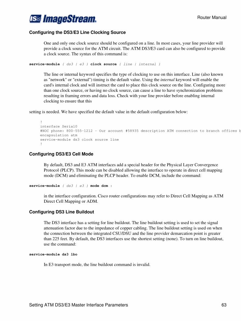
Configuring the DS3/E3 Line Clocking Source
One and only one clock source should be configured on a line. In most cases, your line provider willprovide a clock source for the ATM circuit. The ATM DS3/E3 card can also be configured to providea clock source. The syntax of this command is:
service-module { ds3 | e3 } clock source { line | internal }
The line or internal keyword specifies the type of clocking to use on this interface. Line (also knownas "network" or "external") timing is the default value. Using the internal keyword will enable thecard's internal clock and will instruct the card to place this clock source on the line. Configuring morethan one clock source, or having no clock source, can cause a line to have synchronization problemsresulting in framing errors and data loss. Check with your line provider before enabling internalclocking to ensure that this
setting is needed. We have specified the default value in the default configuration below:
! interface Serial0 #NOC phone: 800-555-1212 - Our account #58935 description ATM connection to branch offices bandwidth 10000000 encapsulation atm service-module ds3 clock source line !
Configuring DS3/E3 Cell Mode
By default, DS3 and E3 ATM interfaces add a special header for the Physical Layer ConvergenceProtocol (PLCP). This mode can be disabled allowing the interface to operate in direct cell mappingmode (DCM) and eliminating the PLCP header. To enable DCM, include the command:
service-module { ds3 | e3 } mode dcm :
in the interface configuration. Cisco router configurations may refer to Direct Cell Mapping as ATMDirect Cell Mapping or ADM.
Configuring DS3 Line Buildout
The DS3 interface has a setting for line buildout. The line buildout setting is used to set the signalattenuation factor due to the impedance of copper cabling. The line buildout setting is used on whenthe connection between the integrated CSU/DSU and the line provider demarcation point is greaterthan 225 feet. By default, the DS3 interfaces use the shortest setting (none). To turn on line buildout,use the command:
service-module ds3 lbo
In E3 transport mode, the line buildout command is invalid.
Router Manual
Setting ATM DS3/E3 Master Interface Parameters 63

Configuring the DS3/E3 Equalizer Gain Limiter
The DS3/E3 interface has an equalizer gain limiter. This setting is used to turn on the receiver gainlimiter to overcome impedance of copper cabling. The gain limiter should be turned on when theconnection between the integrated CSU/DSU and the line provider demarcation point is greater than225 feet. By default, the DS3/E3 interfaces do not enable the gain limiter. To enable the equalizergain limiter, add the command service-module { ds3 | e3 } egl to the interface configuration. Thiscommand is normally used in conjunction with the line buildout command.
Configuring DS3 Framing
By default, ATM DS3 interfaces use c-bit parity for framing. This command is not valid in E3transport mode. To explicitly configure ESF framing, include the framing statement in the interfaceconfiguration for the serial device:
service-module ds3 framing cbit :
You can configure the m23 format as an alternative. To have the interface use the m23 framingformat, include the framing statement in the interface configuration, specifying the m23 option. In thedefault configuration below, we have specified the default c-bit framing:
! interface Serial0 #NOC phone: 800-555-1212 - Our account #58935 description ATM connection to branch offices bandwidth 10000000 encapsulation atm service-module ds3 clock source line service-module ds3 framing cbit !
Configuring DS3/E3 Cell Scrambling
By default, DS3/E3 ATM interfaces enable cell scrambling. Scrambling cells randomizes the ATMcell payload frames to avoid continuous non-variable bit patterns and improves the efficiency ofATM's cell delineation algorithms. Normally, the default setting for this command is sufficient.
To explicitly configure cell scrambling, include the scrambling statement in the interfaceconfiguration for the serial device:
service-module { ds3 | e3 } scrambling on :
You can turn off scrambling as an alternative. To have the interface disable cell scrambling,include the scrambling statement in the interface configuration, specifying the off option. Thissetting must match the remote router or your ATM master interface will not functioncorrectly. In the default configuration below, we have specified the default "scrambling":
! interface Serial0 #NOC phone: 800-555-1212 - Our account #58935 description ATM connection to branch offices bandwidth 10000000 encapsulation atm
Router Manual
64 Setting ATM DS3/E3 Master Interface Parameters
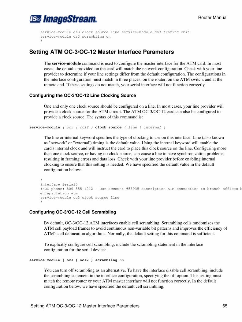
service-module ds3 clock source line service-module ds3 framing cbit service-module ds3 scrambling on !
Setting ATM OC-3/OC-12 Master Interface Parameters
The service-module command is used to configure the master interface for the ATM card. In mostcases, the defaults provided on the card will match the network configuration. Check with your lineprovider to determine if your line settings differ from the default configuration. The configurations inthe interface configuration must match in three places: on the router, on the ATM switch, and at theremote end. If these settings do not match, your serial interface will not function correctly
Configuring the OC-3/OC-12 Line Clocking Source
One and only one clock source should be configured on a line. In most cases, your line provider willprovide a clock source for the ATM circuit. The ATM OC-3/OC-12 card can also be configured toprovide a clock source. The syntax of this command is:
service-module { oc3 | oc12 } clock source { line | internal }
The line or internal keyword specifies the type of clocking to use on this interface. Line (also knownas "network" or "external') timing is the default value. Using the internal keyword will enable thecard's internal clock and will instruct the card to place this clock source on the line. Configuring morethan one clock source, or having no clock source, can cause a line to have synchronization problemsresulting in framing errors and data loss. Check with your line provider before enabling internalclocking to ensure that this setting is needed. We have specified the default value in the defaultconfiguration below:
! interface Serial0 #NOC phone: 800-555-1212 - Our account #58935 description ATM connection to branch offices bandwidth 10000000 encapsulation atm service-module oc3 clock source line !
Configuring OC-3/OC-12 Cell Scrambling
By default, OC-3/OC-12 ATM interfaces enable cell scrambling. Scrambling cells randomizes theATM cell payload frames to avoid continuous non-variable bit patterns and improves the efficiency ofATM's cell delineation algorithms. Normally, the default setting for this command is sufficient.
To explicitly configure cell scrambling, include the scrambling statement in the interfaceconfiguration for the serial device:
service-module { oc3 | oc12 } scrambling on
You can turn off scrambling as an alternative. To have the interface disable cell scrambling, includethe scrambling statement in the interface configuration, specifying the off option. This setting mustmatch the remote router or your ATM master interface will not function correctly. In the defaultconfiguration below, we have specified the default cell scrambling:
Router Manual
Setting ATM OC-3/OC-12 Master Interface Parameters 65
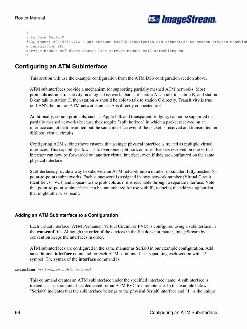
! interface Serial0 #NOC phone: 800-555-1212 - Our account #58935 description ATM connection to branch offices bandwidth 10000000 encapsulation atm service-module oc3 clock source line service-module oc12 scrambling on !
Configuring an ATM Subinterface
This section will use the example configuration from the ATM DS3 configuration section above.
ATM subinterfaces provide a mechanism for supporting partially meshed ATM networks. Mostprotocols assume transitivity on a logical network; that is, if station A can talk to station B, and stationB can talk to station C, then station A should be able to talk to station C directly. Transitivity is trueon LAN's, but not on ATM networks unless A is directly connected to C.
Additionally, certain protocols, such as AppleTalk and transparent bridging, cannot be supported onpartially meshed networks because they require "split horizon" in which a packet received on aninterface cannot be transmitted out the same interface even if the packet is received and transmitted ondifferent virtual circuits.
Configuring ATM subinterfaces ensures that a single physical interface is treated as multiple virtualinterfaces. This capability allows us to overcome split horizon rules. Packets received on one virtualinterface can now be forwarded out another virtual interface, even if they are configured on the samephysical interface.
SubInterfaces provide a way to subdivide an ATM network into a number of smaller, fully meshed (orpoint-to-point) subnetworks. Each subnetwork is assigned its own network number (Virtual CircuitIdentifier, or VCI) and appears to the protocols as if it is reachable through a separate interface. Notethat point-to-point subinterfaces can be unnumbered for use with IP, reducing the addressing burdenthat might otherwise result.
Adding an ATM Subinterface to a Configuration
Each virtual interface (ATM Permanent Virtual Circuit, or PVC) is configured using a subinterface inthe wan.conf file. Although the order of the devices in the file does not matter, ImageStream byconvention keeps the interfaces in order.
ATM subinterfaces are configured in the same manner as Serial0 in our example configuration. Addan additional interface command for each ATM serial interface, separating each section with a !symbol. The syntax of the interface command is:
interface DeviceName.subinterface#
This command creates an ATM subinterface under the specified interface name. A subinterface istreated as a separate interface dedicated for an ATM PVC to a remote site. In the example below,"Serial0" indicates that the subinterface belongs to the physical Serial0 interface and "1" is the unique
Router Manual
66 Configuring an ATM Subinterface
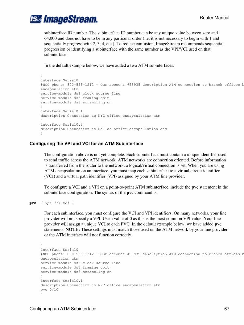
subinterface ID number. The subinterface ID number can be any unique value between zero and64,000 and does not have to be in any particular order (i.e. it is not necessary to begin with 1 andsequentially progress with 2, 3, 4, etc.). To reduce confusion, ImageStream recommends sequentialprogression or identifying a subinterface with the same number as the VPI/VCI used on thatsubinterface.
In the default example below, we have added a two ATM subinterfaces.
! interface Serial0 #NOC phone: 800-555-1212 - Our account #58935 description ATM connection to branch offices bandwidth 10000000 encapsulation atm service-module ds3 clock source line service-module ds3 framing cbit service-module ds3 scrambling on ! interface Serial0.1 description Connection to NYC office encapsulation atm ! interface Serial0.2 description Connection to Dallas office encapsulation atm !
Configuring the VPI and VCI for an ATM Subinterface
The configuration above is not yet complete. Each subinterface must contain a unique identifier usedto send traffic across the ATM network. ATM networks are connection oriented. Before informationis transferred from the router to the network, a logical/virtual connection is set. When you are usingATM encapsulation on an interface, you must map each subinterface to a virtual circuit identifier(VCI) and a virtual path identifier (VPI) assigned by your ATM line provider.
To configure a VCI and a VPI on a point-to-point ATM subinterface, include the pvc statement in thesubinterface configuration. The syntax of the pvc command is:
pvc { vpi }/{ vci }
For each subinterface, you must configure the VCI and VPI identifiers. On many networks, your lineprovider will not specify a VPI. Use a value of 0 as this is the most common VPI value. Your lineprovider will assign a unique VCI to each PVC. In the default example below, we have added pvcstatements. NOTE: These settings must match those used on the ATM network by your line provideror the ATM interface will not function correctly.
! interface Serial0 #NOC phone: 800-555-1212 - Our account #58935 description ATM connection to branch offices bandwidth 10000000 encapsulation atm service-module ds3 clock source line service-module ds3 framing cbit service-module ds3 scrambling on ! interface Serial0.1 description Connection to NYC office encapsulation atm pvc 0/10 !
Router Manual
Configuring an ATM Subinterface 67

interface Serial0.2 description Connection to Dallas office encapsulation atm pvc 1/22 !
Setting the IP Address and Netmask
During the subinterface setup process, you will set the IP address and netmask for the subinterface. Tochange the IP address and netmask of the Serial subinterface, modify the ip address command. Thesyntax of this command is:
ip address ipaddress netmask
Set the IP address to the address to be used by the ATM subinterface of the router on your network. Ifyou have divided your network into subnets, enter the subnet mask that identifies how your networkaddresses are divided between the network portion and the host portion.
Using the default configuration below, we have set the Serial0.1 IP address to 25.0.0.1 with a netmaskof 255.255.255.252. We have also set Serial0.2 to use an IP address of 30.0.0.1 and a /30 subnetmask. Often, with numbered point-to-point Serial links, the netmask will be a /30 (a subnet with 2valid addresses). NOTE: You will need to substitute your address and netmask for your network.
! interface Serial0 #NOC phone: 800-555-1212 - Our account #58935 description ATM connection to branch offices bandwidth 10000000 encapsulation atm service-module ds3 clock source line service-module ds3 framing cbit service-module ds3 scrambling on ! interface Serial0.1 description Connection to NYC office encapsulation atm pvc 0/10 ip address 25.0.0.1 255.255.255.252 ! interface Serial0.2 description Connection to Dallas office encapsulation atm pvc 1/22 ip address 30.0.0.1 255.255.255.252 !
Adding Secondary Serial Addresses
Although rarely necessary, depending on your network configuration, you may need to configuremore than one address on a subinterface. This task is accomplished by adding the secondary keywordto the ip address line used previously. The secondary keyword is used for all addresses on a Serialdevice other than the primary address. Only one primary address can be configured on a Serial device.
NOTE: Configuring more than one primary address or leaving the secondary keyword off of asecondary address configuration will cause the last primary IP address to be used when the port isconfigured by SAND.
Router Manual
68 Configuring an ATM Subinterface
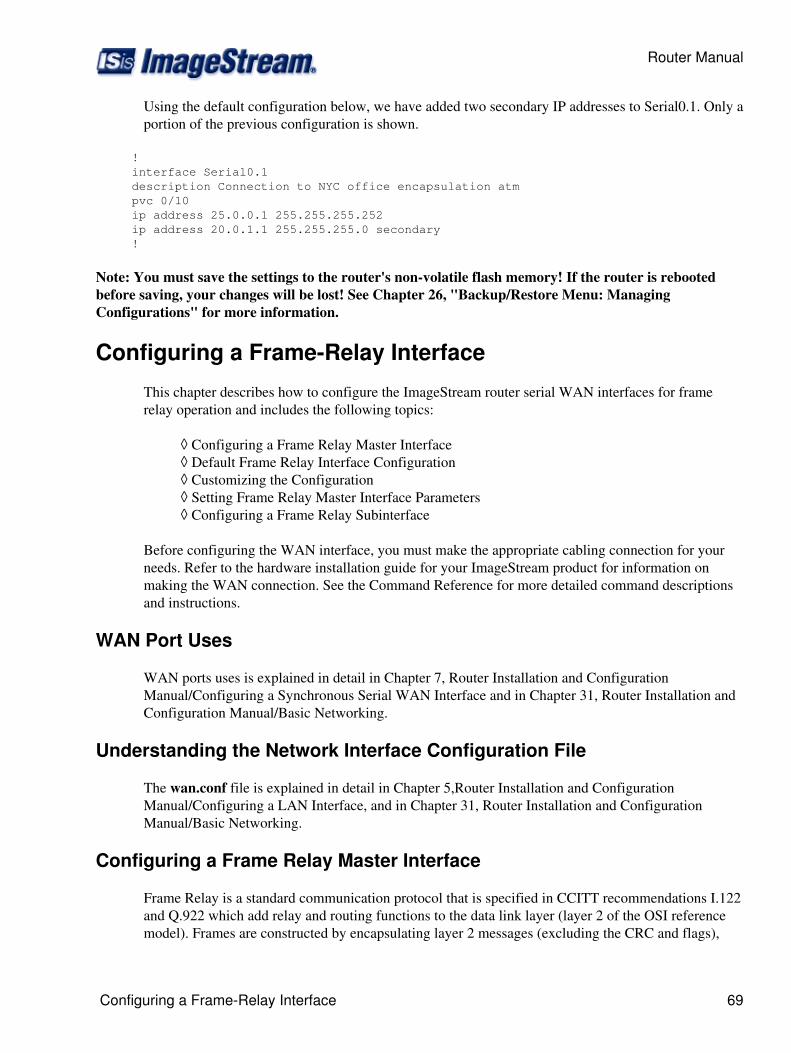
Using the default configuration below, we have added two secondary IP addresses to Serial0.1. Only aportion of the previous configuration is shown.
! interface Serial0.1 description Connection to NYC office encapsulation atm pvc 0/10 ip address 25.0.0.1 255.255.255.252 ip address 20.0.1.1 255.255.255.0 secondary !
Note: You must save the settings to the router's non-volatile flash memory! If the router is rebootedbefore saving, your changes will be lost! See Chapter 26, "Backup/Restore Menu: ManagingConfigurations" for more information.
Configuring a Frame-Relay Interface
This chapter describes how to configure the ImageStream router serial WAN interfaces for framerelay operation and includes the following topics:
Configuring a Frame Relay Master Interface◊ Default Frame Relay Interface Configuration◊ Customizing the Configuration◊ Setting Frame Relay Master Interface Parameters◊ Configuring a Frame Relay Subinterface◊
Before configuring the WAN interface, you must make the appropriate cabling connection for yourneeds. Refer to the hardware installation guide for your ImageStream product for information onmaking the WAN connection. See the Command Reference for more detailed command descriptionsand instructions.
WAN Port Uses
WAN ports uses is explained in detail in Chapter 7, Router Installation and ConfigurationManual/Configuring a Synchronous Serial WAN Interface and in Chapter 31, Router Installation andConfiguration Manual/Basic Networking.
Understanding the Network Interface Configuration File
The wan.conf file is explained in detail in Chapter 5,Router Installation and ConfigurationManual/Configuring a LAN Interface, and in Chapter 31, Router Installation and ConfigurationManual/Basic Networking.
Configuring a Frame Relay Master Interface
Frame Relay is a standard communication protocol that is specified in CCITT recommendations I.122and Q.922 which add relay and routing functions to the data link layer (layer 2 of the OSI referencemodel). Frames are constructed by encapsulating layer 2 messages (excluding the CRC and flags),
Router Manual
Configuring a Frame-Relay Interface 69
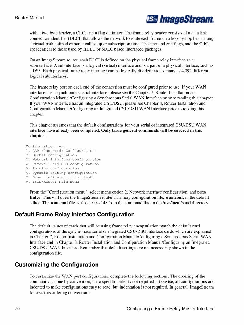
with a two byte header, a CRC, and a flag delimiter. The frame relay header consists of a data linkconnection identifier (DLCI) that allows the network to route each frame on a hop-by-hop basis alonga virtual path defined either at call setup or subscription time. The start and end flags, and the CRCare identical to those used by HDLC or SDLC based interfaced packages.
On an ImageStream router, each DLCI is defined on the physical frame relay interface as asubinterface. A subinterface is a logical (virtual) interface and is a part of a physical interface, such asa DS3. Each physical frame relay interface can be logically divided into as many as 4,092 differentlogical subinterfaces.
The frame relay port on each end of the connection must be configured prior to use. If your WANinterface has a synchronous serial interface, please see the Chapter 7, Router Installation andConfiguration Manual/Configuring a Synchronous Serial WAN Interface prior to reading this chapter.If your WAN interface has an integrated CSU/DSU, please see Chapter 8, Router Installation andConfiguration Manual/Configuring an Integrated CSU/DSU WAN Interface prior to reading thischapter.
This chapter assumes that the default configurations for your serial or integrated CSU/DSU WANinterface have already been completed. Only basic general commands will be covered in thischapter.
Configuration menu 1. AAA (Password) Configuration 2. Global configuration 3. Network interface configuration 4. Firewall and QOS configuration 5. Service configuration 6. Dynamic routing configuration 7. Save configuration to flash 0. ISis-Router main menu
From the "Configuration menu", select menu option 2, Network interface configuration, and pressEnter. This will open the ImageStream router's primary configuration file, wan.conf, in the defaulteditor. The wan.conf file is also accessible from the command line in the /usr/local/sand directory.
Default Frame Relay Interface Configuration
The default values of cards that will be using frame relay encapsulation match the default cardconfigurations of the synchronous serial or integrated CSU/DSU interface cards which are explainedin Chapter 7, Router Installation and Configuration Manual/Configuring a Synchronous Serial WANInterface and in Chapter 8, Router Installation and Configuration Manual/Configuring an IntegratedCSU/DSU WAN Interface. Remember that default settings are not necessarily shown in theconfiguration file.
Customizing the Configuration
To customize the WAN port configurations, complete the following sections. The ordering of thecommands is done by convention, but a specific order is not required. Likewise, all configurations areindented to make configurations easy to read, but indentation is not required. In general, ImageStreamfollows this ordering convention:
Router Manual
70 Configuring a Frame Relay Master Interface
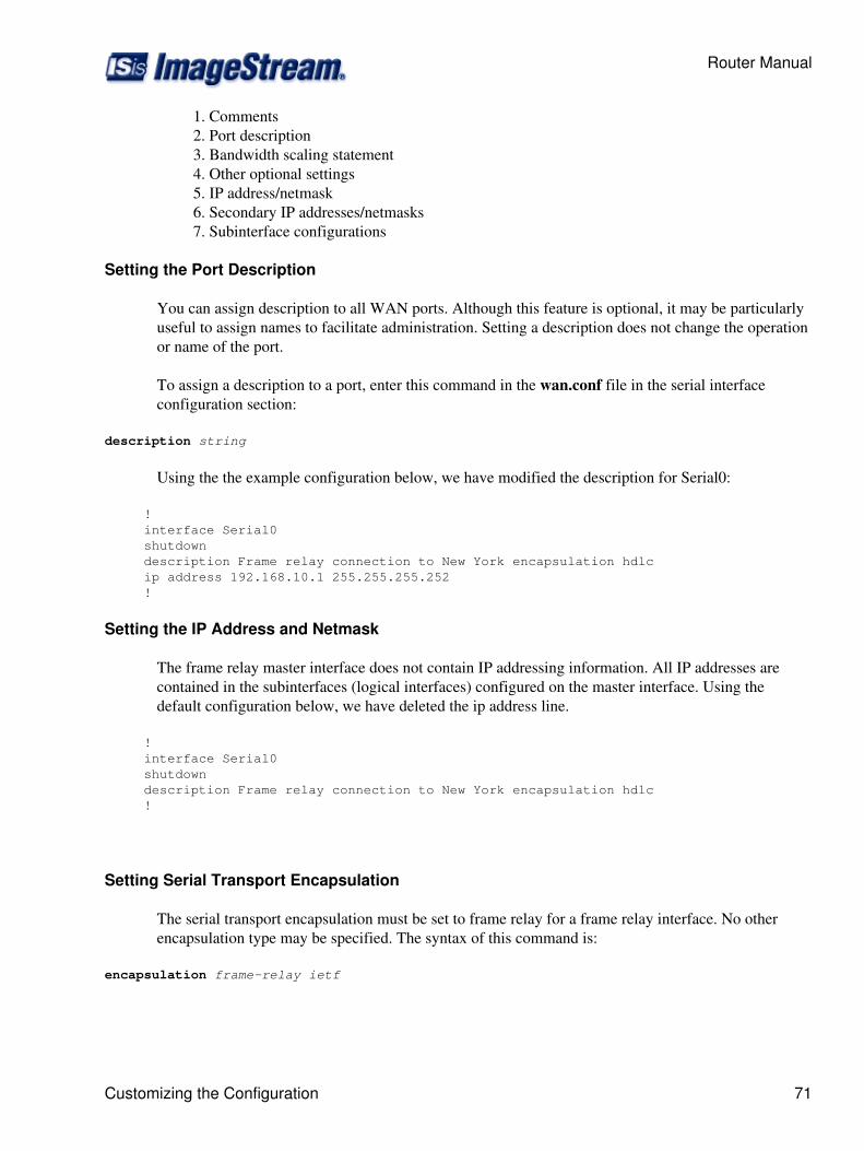
Comments1. Port description2. Bandwidth scaling statement3. Other optional settings4. IP address/netmask5. Secondary IP addresses/netmasks6. Subinterface configurations7.
Setting the Port Description
You can assign description to all WAN ports. Although this feature is optional, it may be particularlyuseful to assign names to facilitate administration. Setting a description does not change the operationor name of the port.
To assign a description to a port, enter this command in the wan.conf file in the serial interfaceconfiguration section:
description string
Using the the example configuration below, we have modified the description for Serial0:
! interface Serial0 shutdown description Frame relay connection to New York encapsulation hdlc ip address 192.168.10.1 255.255.255.252 !
Setting the IP Address and Netmask
The frame relay master interface does not contain IP addressing information. All IP addresses arecontained in the subinterfaces (logical interfaces) configured on the master interface. Using thedefault configuration below, we have deleted the ip address line.
! interface Serial0 shutdown description Frame relay connection to New York encapsulation hdlc !
Setting Serial Transport Encapsulation
The serial transport encapsulation must be set to frame relay for a frame relay interface. No otherencapsulation type may be specified. The syntax of this command is:
encapsulation frame-relay ietf
Router Manual
Customizing the Configuration 71

In the default configuration below, we have changed the encapsulation to IETF frame relay. Thisencapsulation type corresponds to "encapsulation frame-relay ietf" on a Cisco router. Including theietf keyword on a Cisco router when connecting to an ImageStream router is important, since Ciscorouters default to a non-standard frame relay implementation.
! interface Serial0 shutdown description Frame relay connection to New York encapsulation frame-relay ietf !
Enabling or Disabling a Serial Interface
To disable an interface, use the shutdown interface configuration command. Unlike other commandline interfaces, the wan.conf file does not require a "no" version of a command to reverse theoperation. Entering "no" followed by a command will be ignored by SAND.
By default, Serial0 is disabled in the default configuration below because the shutdown command hasbeen entered. Disabling a master interface will also disable all subinterfaces configured on the masterdevice.
! interface Serial0 shutdown description Frame relay connection to New York encapsulation frame-relay ietf !
To enable Serial0 in the configuration, remove the shutdown command. Do not use "no shutdown", asthis will be ignored by SAND. It is not necessary to enter "no" and a command to negate thecommand. Simply remove the command from the configuration file.
Adding Comments to a Serial Configuration
Comments may be added to the Serial configuration, or anywhere in the wan.conf file by inserting aline that begins with the # symbol. The contents of the line will be ignored by SAND. Comments maybe used to place contact information, ticket numbers, circuit IDs or any other information into thewan.conf file. There are no limits on the number or length of comments that may be inserted.
! interface Serial0 #NOC phone: 800-555-1212 - Our account #58935 description Frame relay connection to New York encapsulation frame-relay ietf !
Scaling the Connection Speed Calculation
For some media, such as Ethernet and Token Ring, the bandwidth is fixed; for other media, such asserial lines, you can change the actual bandwidth by adjusting the hardware. For both classes ofmedia, you can use the bandwidth configuration command to communicate the current bandwidth tothe router's statistical output program and other programs. The bandwidth command sets an
Router Manual
72 Customizing the Configuration
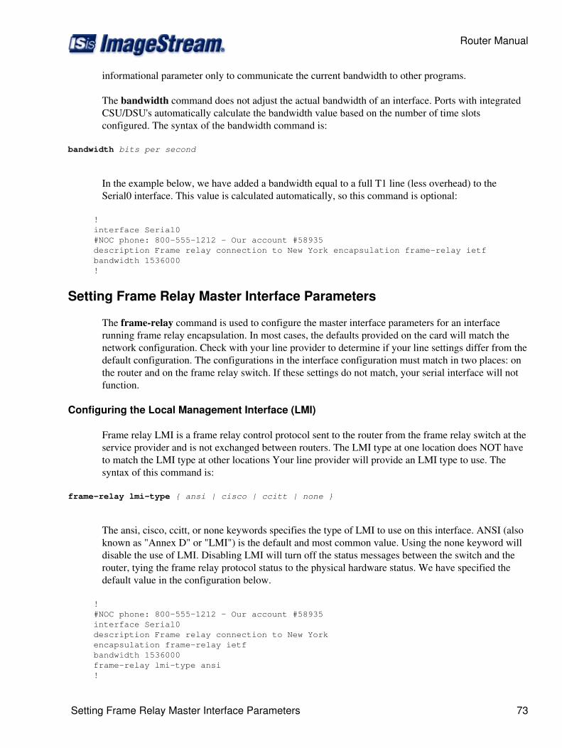
informational parameter only to communicate the current bandwidth to other programs.
The bandwidth command does not adjust the actual bandwidth of an interface. Ports with integratedCSU/DSU's automatically calculate the bandwidth value based on the number of time slotsconfigured. The syntax of the bandwidth command is:
bandwidth bits per second
In the example below, we have added a bandwidth equal to a full T1 line (less overhead) to theSerial0 interface. This value is calculated automatically, so this command is optional:
! interface Serial0 #NOC phone: 800-555-1212 - Our account #58935 description Frame relay connection to New York encapsulation frame-relay ietf bandwidth 1536000 !
Setting Frame Relay Master Interface Parameters
The frame-relay command is used to configure the master interface parameters for an interfacerunning frame relay encapsulation. In most cases, the defaults provided on the card will match thenetwork configuration. Check with your line provider to determine if your line settings differ from thedefault configuration. The configurations in the interface configuration must match in two places: onthe router and on the frame relay switch. If these settings do not match, your serial interface will notfunction.
Configuring the Local Management Interface (LMI)
Frame relay LMI is a frame relay control protocol sent to the router from the frame relay switch at theservice provider and is not exchanged between routers. The LMI type at one location does NOT haveto match the LMI type at other locations Your line provider will provide an LMI type to use. Thesyntax of this command is:
frame-relay lmi-type { ansi | cisco | ccitt | none }
The ansi, cisco, ccitt, or none keywords specifies the type of LMI to use on this interface. ANSI (alsoknown as "Annex D" or "LMI") is the default and most common value. Using the none keyword willdisable the use of LMI. Disabling LMI will turn off the status messages between the switch and therouter, tying the frame relay protocol status to the physical hardware status. We have specified thedefault value in the configuration below.
! #NOC phone: 800-555-1212 - Our account #58935 interface Serial0 description Frame relay connection to New York encapsulation frame-relay ietf bandwidth 1536000 frame-relay lmi-type ansi !
Router Manual
Setting Frame Relay Master Interface Parameters 73
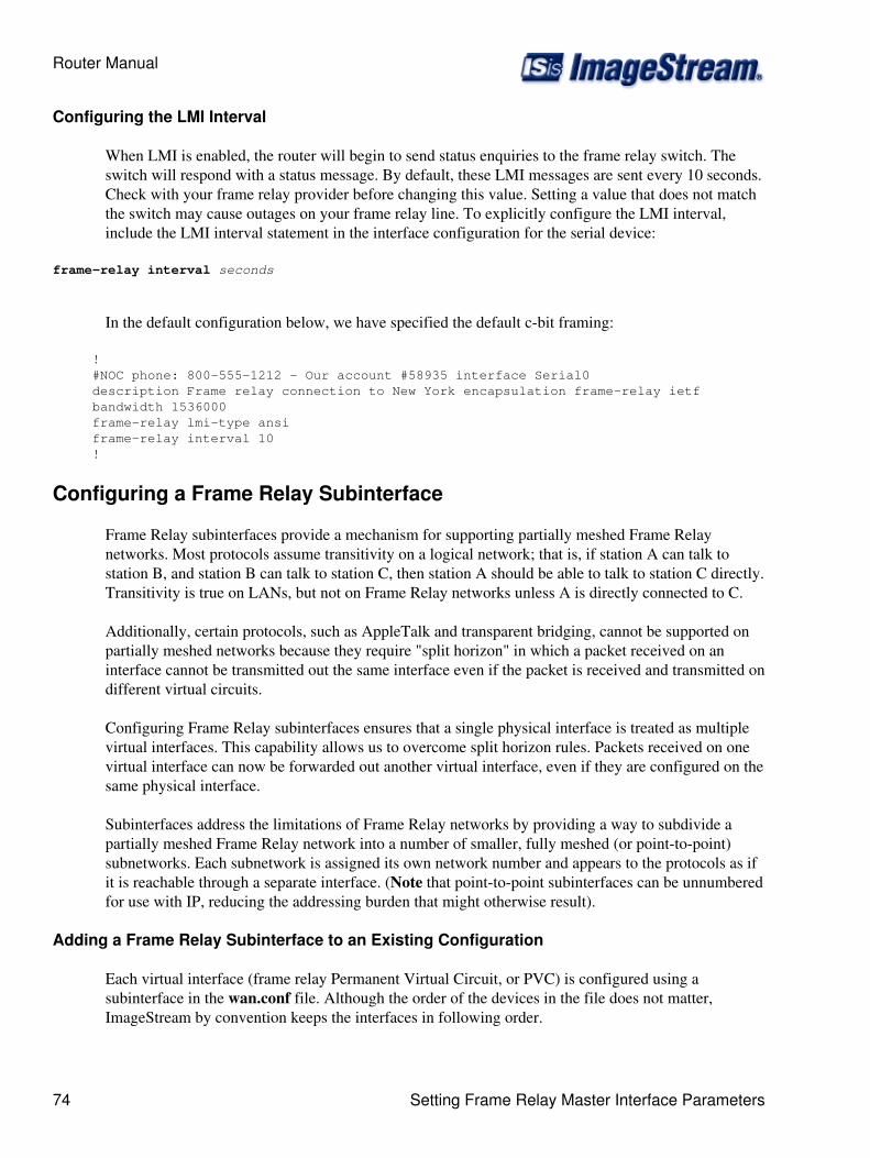
Configuring the LMI Interval
When LMI is enabled, the router will begin to send status enquiries to the frame relay switch. Theswitch will respond with a status message. By default, these LMI messages are sent every 10 seconds.Check with your frame relay provider before changing this value. Setting a value that does not matchthe switch may cause outages on your frame relay line. To explicitly configure the LMI interval,include the LMI interval statement in the interface configuration for the serial device:
frame-relay interval seconds
In the default configuration below, we have specified the default c-bit framing:
! #NOC phone: 800-555-1212 - Our account #58935 interface Serial0 description Frame relay connection to New York encapsulation frame-relay ietf bandwidth 1536000 frame-relay lmi-type ansi frame-relay interval 10 !
Configuring a Frame Relay Subinterface
Frame Relay subinterfaces provide a mechanism for supporting partially meshed Frame Relaynetworks. Most protocols assume transitivity on a logical network; that is, if station A can talk tostation B, and station B can talk to station C, then station A should be able to talk to station C directly.Transitivity is true on LANs, but not on Frame Relay networks unless A is directly connected to C.
Additionally, certain protocols, such as AppleTalk and transparent bridging, cannot be supported onpartially meshed networks because they require "split horizon" in which a packet received on aninterface cannot be transmitted out the same interface even if the packet is received and transmitted ondifferent virtual circuits.
Configuring Frame Relay subinterfaces ensures that a single physical interface is treated as multiplevirtual interfaces. This capability allows us to overcome split horizon rules. Packets received on onevirtual interface can now be forwarded out another virtual interface, even if they are configured on thesame physical interface.
Subinterfaces address the limitations of Frame Relay networks by providing a way to subdivide apartially meshed Frame Relay network into a number of smaller, fully meshed (or point-to-point)subnetworks. Each subnetwork is assigned its own network number and appears to the protocols as ifit is reachable through a separate interface. (Note that point-to-point subinterfaces can be unnumberedfor use with IP, reducing the addressing burden that might otherwise result).
Adding a Frame Relay Subinterface to an Existing Configuration
Each virtual interface (frame relay Permanent Virtual Circuit, or PVC) is configured using asubinterface in the wan.conf file. Although the order of the devices in the file does not matter,ImageStream by convention keeps the interfaces in following order.
Router Manual
74 Setting Frame Relay Master Interface Parameters

Frame relay subinterfaces are configured in the same manner as Serial0 in our example configuration.Add an additional interface command for each frame relay serial interface, separating each sectionwith a ! symbol. The syntax of the interface command is:
interface DeviceName.subinterface#
This command creates a frame relay subinterface under the specified interface name. A subinterface istreated as a separate interface dedicated for a frame relay PVC to a remote site. In the example below,"Serial0" indicates that the subinterface belongs to the physical Serial0 interface and "1" is the uniquesubinterface ID number. The subinterface ID number can be any unique value between zero and 4,096and does not have to be in any particular order (i.e. it is not necessary to begin with 1 and sequentiallyprogress with 2, 3, 4, etc.). To reduce confusion, ImageStream recommends sequential progression foridentifying a subinterface with the same number as the DLCI used on that subinterface.
In the default example below, we have added a two frame relay subinterfaces. Note that we have setthe encapsulation on the subinterfaces to match the master interface.
! #NOC phone: 800-555-1212 - Our account #58935 interface Serial0 description Frame relay connection to New York encapsulation frame-relay ietf bandwidth 1536000 frame-relay lmi-type ansi frame-relay interval 10 ! interface Serial0.1 description Connection to NYC office encapsulation frame-relay ietf ! interface Serial0.2 description Connection to Dallas office encapsulation frame-relay ietf !
Configuring the DLCI for a Frame Relay Subinterface
The configuration above is not yet complete. Each subinterface must contain a unique identifier usedto send traffic across the frame relay network. Frame relay networks are connection oriented. Thiscommand assigns a Data Link Connection Identifier (DLCI) number to the corresponding frame-relaysubinterface. A DLCI is assigned by the local frame relay provider for every Permanent VirtualCircuit (PVC) connected to the router. DLCI numbers are NOT exchanged between routers. DLCInumbering at one frame relay site is mutually exclusive from DLCI numbering at another site. Whenyou are using frame relay encapsulation on an interface, you must map each subinterface to a DLCIassigned by your frame relay line provider.
To configure a DLCI on a point-to-point frame relay subinterface, include the frame-relayinterface-dlci statement in the subinterface configuration. The syntax of the frame-relay interface-dlcicommand is:
frame-relay interface-dlci { dlci }
Router Manual
Configuring a Frame Relay Subinterface 75
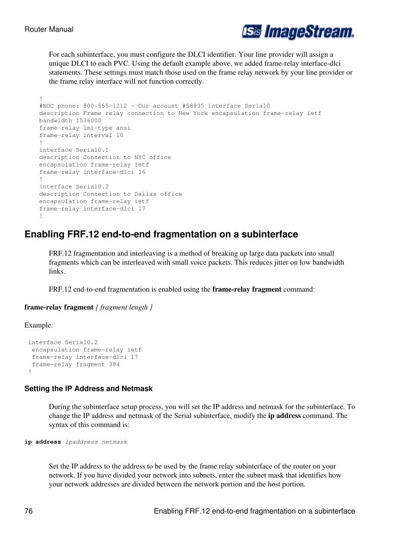
For each subinterface, you must configure the DLCI identifier. Your line provider will assign aunique DLCI to each PVC. Using the default example above, we added frame-relay interface-dlcistatements. These settings must match those used on the frame relay network by your line provider orthe frame relay interface will not function correctly.
! #NOC phone: 800-555-1212 - Our account #58935 interface Serial0 description Frame relay connection to New York encapsulation frame-relay ietf bandwidth 1536000 frame-relay lmi-type ansi frame-relay interval 10 ! interface Serial0.1 description Connection to NYC office encapsulation frame-relay ietf frame-relay interface-dlci 16 ! interface Serial0.2 description Connection to Dallas office encapsulation frame-relay ietf frame-relay interface-dlci 17 !
Enabling FRF.12 end-to-end fragmentation on a subinterface
FRF.12 fragmentation and interleaving is a method of breaking up large data packets into smallfragments which can be interleaved with small voice packets. This reduces jitter on low bandwidthlinks.
FRF.12 end-to-end fragmentation is enabled using the frame-relay fragment command:
frame-relay fragment { fragment length }
Example:
interface Serial0.2 encapsulation frame-relay ietf frame-relay interface-dlci 17 frame-relay fragment 384 !
Setting the IP Address and Netmask
During the subinterface setup process, you will set the IP address and netmask for the subinterface. Tochange the IP address and netmask of the Serial subinterface, modify the ip address command. Thesyntax of this command is:
ip address ipaddress netmask
Set the IP address to the address to be used by the frame relay subinterface of the router on yournetwork. If you have divided your network into subnets, enter the subnet mask that identifies howyour network addresses are divided between the network portion and the host portion.
Router Manual
76 Enabling FRF.12 end-to-end fragmentation on a subinterface
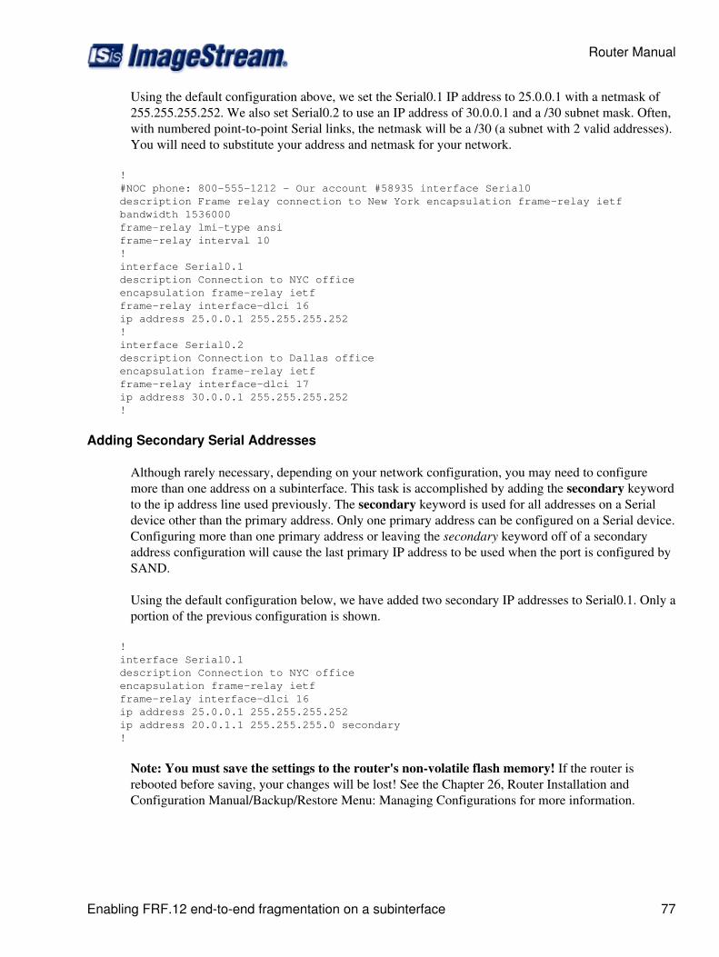
Using the default configuration above, we set the Serial0.1 IP address to 25.0.0.1 with a netmask of255.255.255.252. We also set Serial0.2 to use an IP address of 30.0.0.1 and a /30 subnet mask. Often,with numbered point-to-point Serial links, the netmask will be a /30 (a subnet with 2 valid addresses).You will need to substitute your address and netmask for your network.
! #NOC phone: 800-555-1212 - Our account #58935 interface Serial0 description Frame relay connection to New York encapsulation frame-relay ietf bandwidth 1536000 frame-relay lmi-type ansi frame-relay interval 10 ! interface Serial0.1 description Connection to NYC office encapsulation frame-relay ietf frame-relay interface-dlci 16 ip address 25.0.0.1 255.255.255.252 ! interface Serial0.2 description Connection to Dallas office encapsulation frame-relay ietf frame-relay interface-dlci 17 ip address 30.0.0.1 255.255.255.252 !
Adding Secondary Serial Addresses
Although rarely necessary, depending on your network configuration, you may need to configuremore than one address on a subinterface. This task is accomplished by adding the secondary keywordto the ip address line used previously. The secondary keyword is used for all addresses on a Serialdevice other than the primary address. Only one primary address can be configured on a Serial device.Configuring more than one primary address or leaving the secondary keyword off of a secondaryaddress configuration will cause the last primary IP address to be used when the port is configured bySAND.
Using the default configuration below, we have added two secondary IP addresses to Serial0.1. Only aportion of the previous configuration is shown.
! interface Serial0.1 description Connection to NYC office encapsulation frame-relay ietf frame-relay interface-dlci 16 ip address 25.0.0.1 255.255.255.252 ip address 20.0.1.1 255.255.255.0 secondary !
Note: You must save the settings to the router's non-volatile flash memory! If the router isrebooted before saving, your changes will be lost! See the Chapter 26, Router Installation andConfiguration Manual/Backup/Restore Menu: Managing Configurations for more information.
Router Manual
Enabling FRF.12 end-to-end fragmentation on a subinterface 77

Configuring an ISDN BRI Interface
This chapter describes how to configure the ImageStream router serial WAN interfaces withoutintegrated CSU/DSUs and includes the following topics:
WAN Port Uses◊ Understanding the Network Interface Configuration File◊ Configuring an ISDN BRI Internface◊ Default ISDN BRI Interface Configuration◊ Customizing the Configuration◊ Configuring Additional ISDN BRI Devices◊
Before configuring the WAN interface, you must make the appropriate cabling connection for yourneeds. Refer to the hardware installation guide for your ImageStream product for information onmaking the WAN connection. See the Command Reference for more detailed command descriptionsand instructions.
WAN Port Uses
WAN ports uses is explained in detail in Chapter 7, Router Installation and ConfigurationManual/Configuring a Synchronous Serial WAN Interface and in Chapter 31 Router Installation andConfiguration Manual/Basic Networking.
Understanding the Network Interface Configuration File
The wan.conf file is explained in detail in Chapter 5, Router Installation and ConfigurationManual/Configuring a LAN Interface, and in Chapter 31, Router Installation and ConfigurationManual/Basic Networking.
Configuring an ISDN BRI Interface
ISDN is most commonly used to provide low-cost connectivity between sites that cannot justify thecost of a dedicated high-speed leased line. However, ISDN connections provide more bandwidth thanasynchronous dial-up connections can, as well as quicker call completion - approximately 1 secondinstead of 45 seconds.
ImageStream routers support manual dial-on-demand and automatic ISDN connections using a BRIinterface card and the PPP protocol. BRI supports two 64Kbps B channels for data and one 16Kbps Dchannel for signaling. ISDN ports are available as either a U or S/T interface. The ISDN BRI Uinterface card has the NT1 device integrated in the port, meaning that no modem, CSU/DSU, orexternal terminal adapter is required. For the ISDN S/T interface, the BRI interface requires anexternal terminal adapter to connect from the S/T port to the ISDN line.
Once you have determined the type of synchronous connection to use between your remote locations,the synchronous port on each end of the connection must be configured. If your WAN interface is notan ISDN BRI interface, please see the appropriate chapter in this manual.
Router Manual
78 Configuring an ISDN BRI Interface

Configuration menu 1. AAA (Password) Configuration 2. Global configuration 3. Network interface configuration 4. Firewall and QOS configuration 5. Service configuration 6. Dynamic routing configuration 7. Save configuration to flash 0. ISis-Router main menu
From the "Configuration menu", select menu option 3, Network interface configuration, and pressEnter. This will open the ImageStream router's primary configuration file, wan.conf in the defaulteditor. The wan.conf file is also accessible from the command line in the /usr/local/sand directory.
Default ISDN BRI Interface Configuration
The default values of cards equipped with a basic rate ISDN (BRI) interface are as follows:
U.S. NI-1 switch type is enabled.◊ No port description is configured for any port.◊ PPP encapsulation is enabled.◊ Bridging is not configured.◊
Remember that default settings are not necessarily shown in the configuration file.
Customizing the Configuration
To customize the WAN port configurations, complete the following sections. The ordering of thecommands is done by convention, but a specific order is not required. Likewise, all configurations areindented to make configurations easy to read, but indentation is not required. In general, ImageStreamfollows this ordering convention:
Comments1. Port description2. BRI ISDN configuration settings3. PPP encapsulation settings4. Other optional settings5. IP address/netmask6. Secondary IP addresses/netmasks7.
Setting the Device Name
The default configuration uses "Serial0" as the device name. In this chapter, we will discuss theconfiguration of ISDN BRI interfaces. The interface name used for BRI interfaces is bri. To assignthe proper device name to a port, enter this command in the wan.conf file in the Serial interfaceconfiguration section:
interface briXX
Router Manual
Configuring an ISDN BRI Interface 79
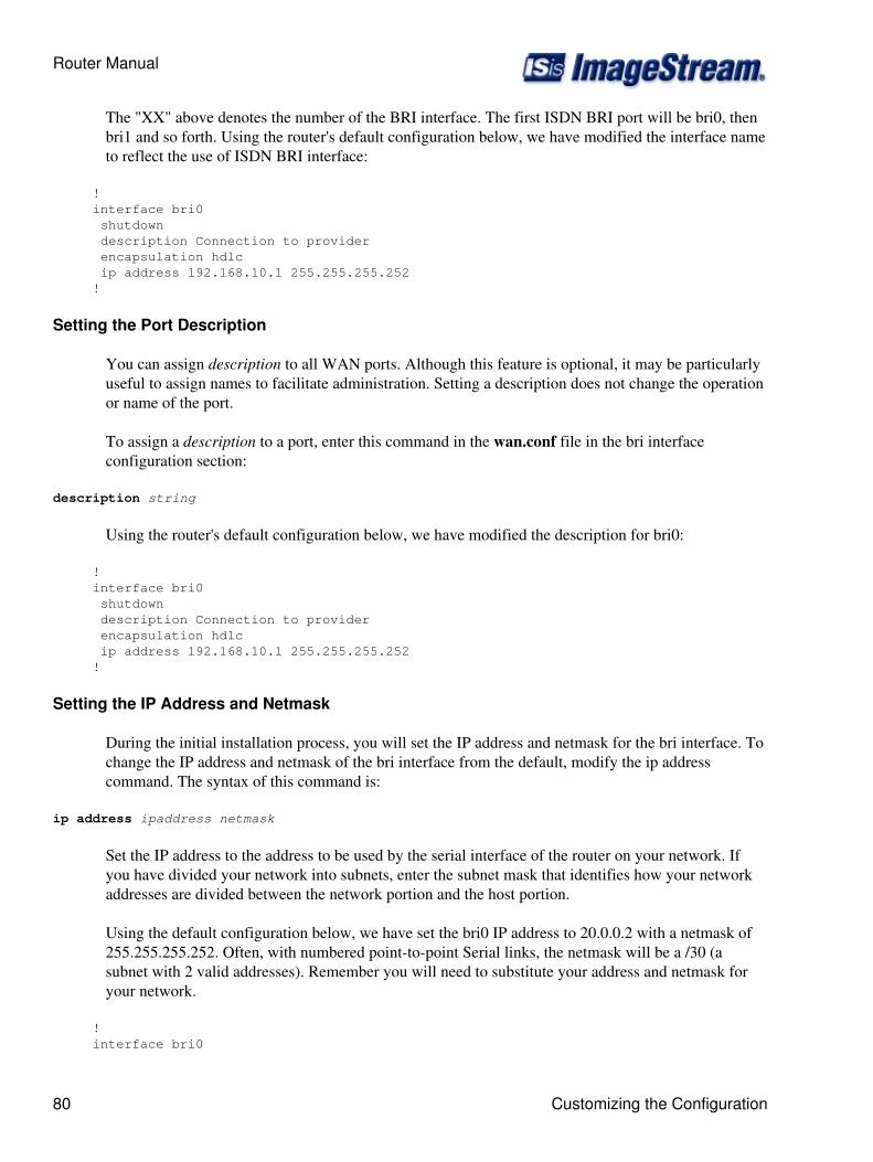
The "XX" above denotes the number of the BRI interface. The first ISDN BRI port will be bri0, thenbri1 and so forth. Using the router's default configuration below, we have modified the interface nameto reflect the use of ISDN BRI interface:
! interface bri0 shutdown description Connection to provider encapsulation hdlc ip address 192.168.10.1 255.255.255.252 !
Setting the Port Description
You can assign description to all WAN ports. Although this feature is optional, it may be particularlyuseful to assign names to facilitate administration. Setting a description does not change the operationor name of the port.
To assign a description to a port, enter this command in the wan.conf file in the bri interfaceconfiguration section:
description string
Using the router's default configuration below, we have modified the description for bri0:
! interface bri0 shutdown description Connection to provider encapsulation hdlc ip address 192.168.10.1 255.255.255.252 !
Setting the IP Address and Netmask
During the initial installation process, you will set the IP address and netmask for the bri interface. Tochange the IP address and netmask of the bri interface from the default, modify the ip addresscommand. The syntax of this command is:
ip address ipaddress netmask
Set the IP address to the address to be used by the serial interface of the router on your network. Ifyou have divided your network into subnets, enter the subnet mask that identifies how your networkaddresses are divided between the network portion and the host portion.
Using the default configuration below, we have set the bri0 IP address to 20.0.0.2 with a netmask of255.255.255.252. Often, with numbered point-to-point Serial links, the netmask will be a /30 (asubnet with 2 valid addresses). Remember you will need to substitute your address and netmask foryour network.
! interface bri0
Router Manual
80 Customizing the Configuration

shutdown description Connection to provider encapsulation hdlc ip address 20.0.0.2 255.255.255.252 !
Setting Serial Transport Encapsulation
The serial transport encapsulation must be set to PPP for an ISDN BRI port. The syntax of thiscommand is:
encapsulation ppp
In the default configuration below, we specified PPP encapsulation. This encapsulation type is theonly valid type for ISDN BRI interfaces.
! interface bri0 shutdown description Connection to provider encapsulation ppp ip address 20.0.0.2 255.255.255.252 !
Enabling or Disabling a Serial Interface
To disable an interface, use the shutdown interface configuration command. Unlike other commandline interfaces, the wan.conf file does not require a "no" version of a command to reverse theoperation. Entering "no" followed by a command will be ignored by SAND.
By default, bri0 is disabled in the default configuration below because the shutdown command hasbeen entered.
! interface bri0 shutdown description Connection to provider encapsulation hdlc ip address 20.0.0.2 255.255.255.252 !
To enable bri0 in the configuration, remove the shutdown command. Do not use "no shutdown", asthis will be ignored by SAND. It is not necessary to enter "no" and a command to negate thecommand. Simply remove the command from the configuration file.
Adding Comments to a Serial Configuration
Comments may be added to the Serial configuration, or anywhere in the wan.conf file by inserting aline that begins with the # symbol. The contents of the line will be ignored by SAND. Comments maybe used to place contact information, ticket numbers, circuit IDs or any other information into thewan.conf file. There are no limits on the number or length of comments that may be inserted.
Router Manual
Customizing the Configuration 81
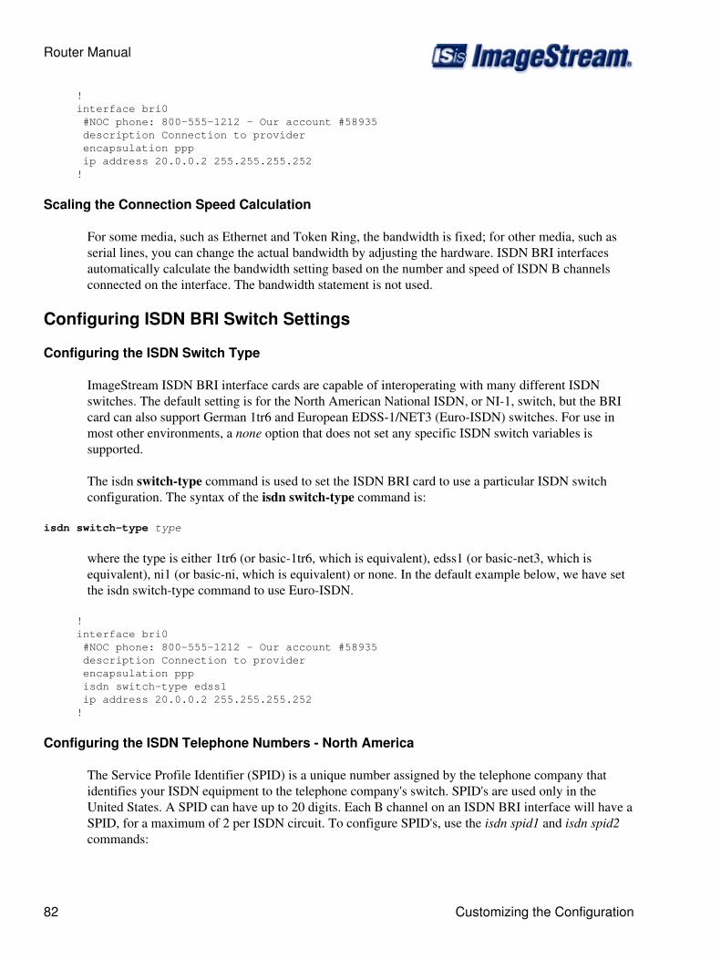
! interface bri0 #NOC phone: 800-555-1212 - Our account #58935 description Connection to provider encapsulation ppp ip address 20.0.0.2 255.255.255.252 !
Scaling the Connection Speed Calculation
For some media, such as Ethernet and Token Ring, the bandwidth is fixed; for other media, such asserial lines, you can change the actual bandwidth by adjusting the hardware. ISDN BRI interfacesautomatically calculate the bandwidth setting based on the number and speed of ISDN B channelsconnected on the interface. The bandwidth statement is not used.
Configuring ISDN BRI Switch Settings
Configuring the ISDN Switch Type
ImageStream ISDN BRI interface cards are capable of interoperating with many different ISDNswitches. The default setting is for the North American National ISDN, or NI-1, switch, but the BRIcard can also support German 1tr6 and European EDSS-1/NET3 (Euro-ISDN) switches. For use inmost other environments, a none option that does not set any specific ISDN switch variables issupported.
The isdn switch-type command is used to set the ISDN BRI card to use a particular ISDN switchconfiguration. The syntax of the isdn switch-type command is:
isdn switch-type type
where the type is either 1tr6 (or basic-1tr6, which is equivalent), edss1 (or basic-net3, which isequivalent), ni1 (or basic-ni, which is equivalent) or none. In the default example below, we have setthe isdn switch-type command to use Euro-ISDN.
! interface bri0 #NOC phone: 800-555-1212 - Our account #58935 description Connection to provider encapsulation ppp isdn switch-type edss1 ip address 20.0.0.2 255.255.255.252 !
Configuring the ISDN Telephone Numbers - North America
The Service Profile Identifier (SPID) is a unique number assigned by the telephone company thatidentifies your ISDN equipment to the telephone company's switch. SPID's are used only in theUnited States. A SPID can have up to 20 digits. Each B channel on an ISDN BRI interface will have aSPID, for a maximum of 2 per ISDN circuit. To configure SPID's, use the isdn spid1 and isdn spid2commands:
Router Manual
82 Customizing the Configuration

isdn spid1 numberisdn spid2 number
These numbers will be assigned by the telephone company. Enter the commands into the briconfiguration, for example:
! interface bri0 #NOC phone: 800-555-1212 - Our account #58935 description Connection to provider encapsulation ppp isdn switch-type basic-ni isdn spid1 5551212 isdn spid2 5551213 ip address 20.0.0.2 255.255.255.252 !
Configuring the ISDN Telephone Numbers - Europe/Germany
Euro-ISDN subscribers can assign more than one ISDN number to an ISDN line. For example, anISDN line could have the numbers 1234567 and 1234568. Each of these numbers could be used todial into the ISDN line. These numbers are referred to as Multiple Subscriber Numbers (MSN).German ISDN networking uses a similar concept called EAZ numbering.
For dial-out ISDN interfaces, the MSN/EAZ number specifies the outgoing phone number. For dial-inISDN interfaces, the MSN/EAZ number specifies the phone number that will be answered. If you areunsure of your MSN/EAZ number, or do not know if you should use one, do not enter thesecommands. To configure an MSN or EAZ, use the isdn msn or equivalent isdn eaz command:
isdn msn numberisdn eaz number
This number will be assigned by the telephone company. Both commands function in the samemanner. Enter the command into the bri configuration, for example:
! interface bri0 #NOC phone: 800-555-1212 - Our account #58935 description Connection to provider encapsulation ppp isdn switch-type edss1 isdn msn 5551212 ip address 20.0.0.2 255.255.255.252 !
Configuring ISDN BRI Interface Characteristics
Configuring Incoming Call Acceptance
By default BRI interface accept and answer all incoming calls. You can specify that the router verifythe incoming phone number, if the number is delivered by the ISDN switch. To limit inbound calls tospecific phone numbers, use the isdn callin command:
Router Manual
Configuring ISDN BRI Switch Settings 83
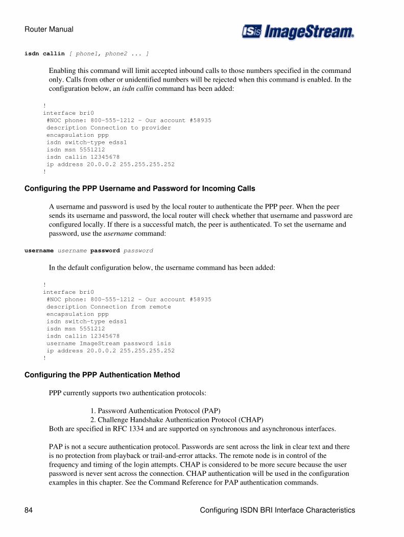
isdn callin [ phone1, phone2 ... ]
Enabling this command will limit accepted inbound calls to those numbers specified in the commandonly. Calls from other or unidentified numbers will be rejected when this command is enabled. In theconfiguration below, an isdn callin command has been added:
! interface bri0 #NOC phone: 800-555-1212 - Our account #58935 description Connection to provider encapsulation ppp isdn switch-type edss1 isdn msn 5551212 isdn callin 12345678 ip address 20.0.0.2 255.255.255.252 !
Configuring the PPP Username and Password for Incoming Calls
A username and password is used by the local router to authenticate the PPP peer. When the peersends its username and password, the local router will check whether that username and password areconfigured locally. If there is a successful match, the peer is authenticated. To set the username andpassword, use the username command:
username username password password
In the default configuration below, the username command has been added:
! interface bri0 #NOC phone: 800-555-1212 - Our account #58935 description Connection from remote encapsulation ppp isdn switch-type edss1 isdn msn 5551212 isdn callin 12345678 username ImageStream password isis ip address 20.0.0.2 255.255.255.252 !
Configuring the PPP Authentication Method
PPP currently supports two authentication protocols:
Password Authentication Protocol (PAP)1. Challenge Handshake Authentication Protocol (CHAP)2.
Both are specified in RFC 1334 and are supported on synchronous and asynchronous interfaces.
PAP is not a secure authentication protocol. Passwords are sent across the link in clear text and thereis no protection from playback or trail-and-error attacks. The remote node is in control of thefrequency and timing of the login attempts. CHAP is considered to be more secure because the userpassword is never sent across the connection. CHAP authentication will be used in the configurationexamples in this chapter. See the Command Reference for PAP authentication commands.
Router Manual
84 Configuring ISDN BRI Interface Characteristics
The authentication method is set using the ppp authentication command:
ppp authentication [ pap | chap ]
Configuring the PPP Username and Password for Remote Authentication
A username and password can be used by the remote router to authenticate the local PPP peer. Whenthe local peer sends its username and password, the remote router will check whether that usernameand password are configured locally. If there is a successful match, the peer is authenticated. Thiscommand is used when remote authentication is required upon dialin or with outgoing calls. To setthe remote username and password for CHAP, use the ppp chap hostname command:
ppp chap hostname username password password
In the configuration below, the ppp chap hostname command has been added:
! interface bri0 #NOC phone: 800-555-1212 - Our account #58935 description Connection to provider encapsulation ppp isdn switch-type edss1 isdn msn 5551212 isdn callin 12345678 ppp authentication chap ppp chap hostname ImageStream password isis ip address 20.0.0.2 255.255.255.252 !
Configuring Multilink PPP (MLPPP)
Defined by RFC 1990, Multilink PPP (MLPPP) allows devices to send data over multiplepoint-to-point data links to the same destination by implementing a virtual link. The MLPPPconnection has a maximum bandwidth equal to the sum of the bandwidths of the component links.For ISDN BRI connections, MLPPP is used to bond both B channels together into a single 112Kbpsor 128 Kbps connection.
For MLPPP operation, enter the ppp multilink command.
Configuring ISDN BRI for Dial-On-Demand and Dial-Backup
A backup interface is an interface that stays idle until certain circumstances occur; then it is activated.A backup interface for a serial interface can be an ISDN interface or a different serial interface. Abackup interface can be configured to be activated when any of the following three circumstancesoccurs:
The primary line goes down.1. The load on the primary ISDN B channel reaches a certain threshold.2. Traffic is sent to a particular IP address or the next hop address.3.
Router Manual
Configuring ISDN BRI Interface Characteristics 85
Configuring Dial-on-Demand for a Second B Channel
You can configure dial-on-demand to activate the secondary B channel based on the traffic load onthe primary B channel. The router monitors the traffic load and computes a 5-minute moving averagebased on a value out of 255. If this average exceeds the value you set for the line, the secondary Bchannel is activated and, depending upon how the line is configured, some or all of the traffic willflow onto the secondary dialup line.
Use the isdn load-threshold command to set the load average that triggers the second B channel. Thevalue is a number from 0 to 255, with 255 being the heaviest load:
isdn load-threshold value
In the default configuration below, we have set the threshold to 100 out of 255, which is about 3137bps (100/255 is .392 * 8000 Bps for a 64 Kbps B channel = 3137).
! interface bri0 #NOC phone: 800-555-1212 - Our account #58935 description Connection to provider encapsulation ppp isdn switch-type edss1 isdn msn 5551212 isdn callin 12345678 username ImageStream password isis ppp authentication chap ppp chap hostname ImageStream password isis isdn load-threshold 100 ip address 20.0.0.2 255.255.255.252 !
Enabling Dial-Backup for ISDN BRI
You can configure dial-on-demand to activate the ISDN BRI interface when traffic is sent to theinterface. To specify that dial-on-demand routing is to be supported, use the dialer in-band commandin interface configuration mode. Adding this command to the configuration will instruct the router tobring up this link when traffic is sent to the device. If dialer in-band is not specified, the router willassume that the BRI port is a dedicated line and will dial-out automatically and remain connected.
In the default configuration below, we have removed the isdn load-threshold command and addeddialer in-band for use with dial-on-demand routing.
! interface bri0 #NOC phone: 800-555-1212 - Our account #58935 description Connection to provider encapsulation ppp isdn switch-type edss1 isdn msn 5551212 isdn callin 12345678 username ImageStream password isis
Router Manual
86 Configuring ISDN BRI for Dial-On-Demand and Dial-Backup
ppp authentication chap ppp chap hostname remote password isis1234 dialer in-band ip address 20.0.0.2 255.255.255.252 !
Configuring Dial-Backup Parameters
To configure a serial interface or ISDN interface to call one or multiple sites or to receive calls frommultiple sites, use a form of the dialer map ip command. This command instructs the dialer toauthenticate or place a call when traffic is received for the specified IP address.
If the router will be connecting to a remote site, you can specify a dial string and an optional speedparameter using the dialer map ip command. This option informs the ISDN software whether itshould place a call at 56 or 64 Kbps. If you omit the ISDN speed parameter, the default is 64 Kbps.The syntax of the dialer map ip command is:
dialer map ip next-hop-address [broadcast] [name hostname] [speed 56 | speed 64] [dial-string]
In the default configuration below, we have instructed the dialer to dial the remote system "core"using B channel speeds of 64 Kbps when traffic is received for the default gateway (0.0.0.0).
Dial-in router:
! interface bri0 description Dial-in ISDN link encapsulation ppp isdn switch-type edss1 isdn msn 8675309 isdn callin 5551212 username ImageStream password isis ip address 20.0.0.1 255.255.255.252 !
Dial-out router:
! interface bri0 description Dial-out ISDN link encapsulation ppp isdn switch-type edss1 isdn msn 5551212 ppp authentication chap ppp chap hostname ImageStream password isis dialer in-band # First B channel dials 8675309 dialer map ip 0.0.0.0 name core 8675309 # Second B channel dials 8675308 dialer map ip 0.0.0.0 name core 8675308 ip address 20.0.0.2 255.255.255.252 !
Router Manual
Configuring ISDN BRI for Dial-On-Demand and Dial-Backup 87
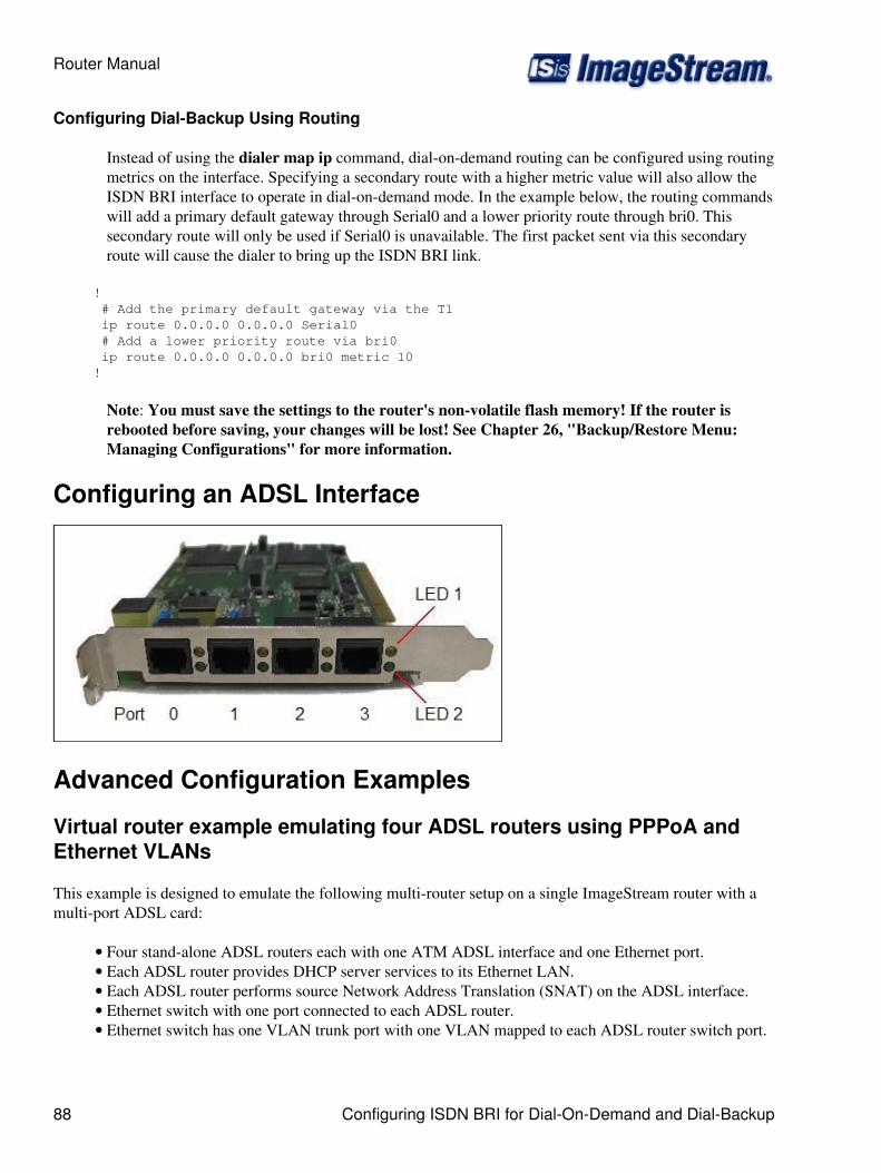
Configuring Dial-Backup Using Routing
Instead of using the dialer map ip command, dial-on-demand routing can be configured using routingmetrics on the interface. Specifying a secondary route with a higher metric value will also allow theISDN BRI interface to operate in dial-on-demand mode. In the example below, the routing commandswill add a primary default gateway through Serial0 and a lower priority route through bri0. Thissecondary route will only be used if Serial0 is unavailable. The first packet sent via this secondaryroute will cause the dialer to bring up the ISDN BRI link.
! # Add the primary default gateway via the T1 ip route 0.0.0.0 0.0.0.0 Serial0 # Add a lower priority route via bri0 ip route 0.0.0.0 0.0.0.0 bri0 metric 10 !
Note: You must save the settings to the router's non-volatile flash memory! If the router isrebooted before saving, your changes will be lost! See Chapter 26, "Backup/Restore Menu:Managing Configurations" for more information.
Configuring an ADSL Interface
Advanced Configuration Examples
Virtual router example emulating four ADSL routers using PPPoA andEthernet VLANs
This example is designed to emulate the following multi-router setup on a single ImageStream router with amulti-port ADSL card:
Four stand-alone ADSL routers each with one ATM ADSL interface and one Ethernet port.• Each ADSL router provides DHCP server services to its Ethernet LAN.• Each ADSL router performs source Network Address Translation (SNAT) on the ADSL interface.• Ethernet switch with one port connected to each ADSL router.• Ethernet switch has one VLAN trunk port with one VLAN mapped to each ADSL router switch port.•
Router Manual
88 Configuring ISDN BRI for Dial-On-Demand and Dial-Backup

Ethernet VLAN specifications:
Four Ethernet VLANs•
VLAN Interface ADSL Interface VLAN IP Address VLAN DHCP SubnetEthernet1.10 ADSL0 192.168.10.1/24 192.168.10.0/24Ethernet1.11 ADSL1 192.168.11.1/24 192.168.11.0/24Ethernet1.12 ADSL2 192.168.12.1/24 192.168.12.0/24Ethernet1.13 ADSL3 192.168.13.1/24 192.168.13.0/24
Each VLAN may only transmit on one ADSL interface• Each VLAN must provide DHCP server services•
ADSL specifications:
Four ADSL interfaces:•
ADSLInterface
ATMInterface VPI/VCI ATM
Encapsulation PPP Username VLAN Interface
ADSL0 Serial0.1 8/35 VC-Mux [email protected] Ethernet1.10ADSL1 Serial1.1 8/35 VC-Mux [email protected] Ethernet1.11ADSL2 Serial2.1 8/35 VC-Mux [email protected] Ethernet1.12ADSL3 Serial3.1 8/35 SNAP/LLC [email protected] Ethernet1.13
Each ADSL interface must source NAT for its VLAN•
wan.conf:
interface Ethernet1 ! interface Ethernet1.10 ip address 192.168.10.1 255.255.255.0 ! interface Ethernet1.11 ip address 192.168.11.1 255.255.255.0 ! interface Ethernet1.12 ip address 192.168.12.1 255.255.255.0 ! interface Ethernet1.13 ip address 192.168.13.1 255.255.255.0 ! interface Serial0 encapsulation atm ! interface Serial0.1 encapsulation aal5mux ppp pvc 8/35 ! interface Serial1 encapsulation atm
Router Manual
Virtual router example emulating four ADSL routers using PPPoA andEthernet VLANs 89

! interface Serial1.1 encapsulation aal5mux ppp pvc 8/35 ! interface Serial2 encapsulation atm ! interface Serial2.1 encapsulation aal5mux ppp pvc 8/35 ! interface Serial3 encapsulation atm ! interface Serial3.1 encapsulation aal5snap pvc 8/35 ! interface ADSL0 adsl device Serial0.1 protocol pppoa ip address negotiated ppp pap sent-username [email protected] password mypass ! interface ADSL1 adsl device Serial1.1 protocol pppoa ip address negotiated ppp pap sent-username [email protected] password mypass ! interface ADSL2 adsl device Serial2.1 protocol pppoa ip address negotiated ppp pap sent-username [email protected] password mypass ! interface ADSL3 adsl device Serial3.1 protocol pppoa ip address negotiated ppp pap sent-username [email protected] password mypass ! # Link Ethernet0.10 to ADSL0 ip rule add fwmark 0x10 table 10 ip route add default dev ADSL0 table 10
# Link Ethernet0.11 to ADSL1 ip rule add fwmark 0x11 table 11 ip route add default dev ADSL1 table 11
# Link Ethernet0.12 to ADSL2 ip rule add fwmark 0x12 table 12 ip route add default dev ADSL2 table 12
# Link Ethernet0.13 to ADSL3 ip rule add fwmark 0x13 table 13 ip route add default dev ADSL3 table 13 ! ip dhcp pool 0
Router Manual
90 Virtual router example emulating four ADSL routers using PPPoA andEthernet VLANs
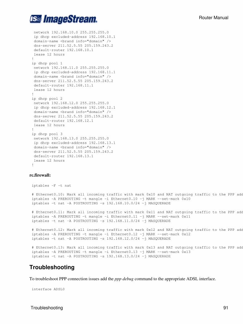
network 192.168.10.0 255.255.255.0 ip dhcp excluded-address 192.168.10.1 domain-name <brand info="domain" /> dns-server 211.52.5.55 205.159.243.2 default-router 192.168.10.1 lease 12 hours ! ip dhcp pool 1 network 192.168.11.0 255.255.255.0 ip dhcp excluded-address 192.168.11.1 domain-name <brand info="domain" /> dns-server 211.52.5.55 205.159.243.2 default-router 192.168.11.1 lease 12 hours ! ip dhcp pool 2 network 192.168.12.0 255.255.255.0 ip dhcp excluded-address 192.168.12.1 domain-name <brand info="domain" /> dns-server 211.52.5.55 205.159.243.2 default-router 192.168.12.1 lease 12 hours ! ip dhcp pool 3 network 192.168.13.0 255.255.255.0 ip dhcp excluded-address 192.168.13.1 domain-name <brand info="domain" /> dns-server 211.52.5.55 205.159.243.2 default-router 192.168.13.1 lease 12 hours !
rc.firewall:
iptables -F -t nat
# Ethernet0.10: Mark all incoming traffic with mark 0x10 and NAT outgoing traffic to the PPP address iptables -A PREROUTING -t mangle -i Ethernet0.10 -j MARK --set-mark 0x10 iptables -t nat -A POSTROUTING -s 192.168.10.0/24 -j MASQUERADE
# Ethernet0.11: Mark all incoming traffic with mark 0x11 and NAT outgoing traffic to the PPP address iptables -A PREROUTING -t mangle -i Ethernet0.11 -j MARK --set-mark 0x11 iptables -t nat -A POSTROUTING -s 192.168.11.0/24 -j MASQUERADE
# Ethernet0.12: Mark all incoming traffic with mark 0x12 and NAT outgoing traffic to the PPP address iptables -A PREROUTING -t mangle -i Ethernet0.12 -j MARK --set-mark 0x12 iptables -t nat -A POSTROUTING -s 192.168.12.0/24 -j MASQUERADE
# Ethernet0.13: Mark all incoming traffic with mark 0x13 and NAT outgoing traffic to the PPP address iptables -A PREROUTING -t mangle -i Ethernet0.13 -j MARK --set-mark 0x13 iptables -t nat -A POSTROUTING -s 192.168.13.0/24 -j MASQUERADE
Troubleshooting
To troubleshoot PPP connection issues add the ppp debug command to the appropriate ADSL interface.
interface ADSL0
Router Manual
Troubleshooting 91
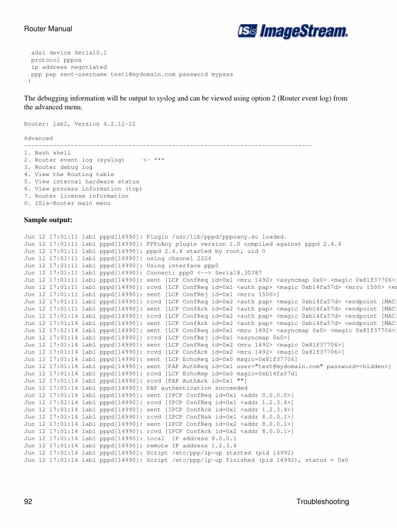
adsl device Serial0.1 protocol pppoa ip address negotiated ppp pap sent-username [email protected] password mypass !
The debugging information will be output to syslog and can be viewed using option 2 (Router event log) fromthe advanced menu.
Router: lab2, Version 4.2.12-22
Advanced--------------------------------------------------------------------------------1. Bash shell2. Router event log (syslog) <- ***3. Router debug log4. View the Routing table5. View internal hardware status6. View process information (top)7. Router license information0. ISis-Router main menu
Sample output:
Jun 12 17:01:11 lab1 pppd[14990]: Plugin /usr/lib/pppd/pppoany.so loaded.Jun 12 17:01:11 lab1 pppd[14990]: PPPoAny plugin version 1.0 compiled against pppd 2.4.4Jun 12 17:01:11 lab1 pppd[14990]: pppd 2.4.4 started by root, uid 0Jun 12 17:01:11 lab1 pppd[14990]: using channel 2224Jun 12 17:01:11 lab1 pppd[14990]: Using interface ppp0Jun 12 17:01:11 lab1 pppd[14990]: Connect: ppp0 <--> Serial8.30387Jun 12 17:01:11 lab1 pppd[14990]: sent [LCP ConfReq id=0x1 <mru 1492> <asyncmap 0x0> <magic 0x81f37706>]Jun 12 17:01:11 lab1 pppd[14990]: rcvd [LCP ConfReq id=0x1 <auth pap> <magic 0xb14fa57d> <mrru 1500> <endpoint [MAC:00:1b:21:03:8e:f1]>]Jun 12 17:01:11 lab1 pppd[14990]: sent [LCP ConfRej id=0x1 <mrru 1500>]Jun 12 17:01:11 lab1 pppd[14990]: rcvd [LCP ConfReq id=0x2 <auth pap> <magic 0xb14fa57d> <endpoint [MAC:00:1b:21:03:8e:f1]>]Jun 12 17:01:11 lab1 pppd[14990]: sent [LCP ConfAck id=0x2 <auth pap> <magic 0xb14fa57d> <endpoint [MAC:00:1b:21:03:8e:f1]>]Jun 12 17:01:14 lab1 pppd[14990]: rcvd [LCP ConfReq id=0x2 <auth pap> <magic 0xb14fa57d> <endpoint [MAC:00:1b:21:03:8e:f1]>]Jun 12 17:01:14 lab1 pppd[14990]: sent [LCP ConfAck id=0x2 <auth pap> <magic 0xb14fa57d> <endpoint [MAC:00:1b:21:03:8e:f1]>]Jun 12 17:01:14 lab1 pppd[14990]: sent [LCP ConfReq id=0x1 <mru 1492> <asyncmap 0x0> <magic 0x81f37706>]Jun 12 17:01:14 lab1 pppd[14990]: rcvd [LCP ConfRej id=0x1 <asyncmap 0x0>]Jun 12 17:01:14 lab1 pppd[14990]: sent [LCP ConfReq id=0x2 <mru 1492> <magic 0x81f37706>]Jun 12 17:01:14 lab1 pppd[14990]: rcvd [LCP ConfAck id=0x2 <mru 1492> <magic 0x81f37706>]Jun 12 17:01:14 lab1 pppd[14990]: sent [LCP EchoReq id=0x0 magic=0x81f37706]Jun 12 17:01:14 lab1 pppd[14990]: sent [PAP AuthReq id=0x1 user="[email protected]" password=<hidden>]Jun 12 17:01:14 lab1 pppd[14990]: rcvd [LCP EchoRep id=0x0 magic=0xb14fa57d]Jun 12 17:01:14 lab1 pppd[14990]: rcvd [PAP AuthAck id=0x1 ""]Jun 12 17:01:14 lab1 pppd[14990]: PAP authentication succeededJun 12 17:01:14 lab1 pppd[14990]: sent [IPCP ConfReq id=0x1 <addr 0.0.0.0>]Jun 12 17:01:14 lab1 pppd[14990]: rcvd [IPCP ConfReq id=0x1 <addr 1.2.3.4>]Jun 12 17:01:14 lab1 pppd[14990]: sent [IPCP ConfAck id=0x1 <addr 1.2.3.4>]Jun 12 17:01:14 lab1 pppd[14990]: rcvd [IPCP ConfNak id=0x1 <addr 8.0.0.1>]Jun 12 17:01:14 lab1 pppd[14990]: sent [IPCP ConfReq id=0x2 <addr 8.0.0.1>]Jun 12 17:01:14 lab1 pppd[14990]: rcvd [IPCP ConfAck id=0x2 <addr 8.0.0.1>]Jun 12 17:01:14 lab1 pppd[14990]: local IP address 8.0.0.1Jun 12 17:01:14 lab1 pppd[14990]: remote IP address 1.2.3.4Jun 12 17:01:14 lab1 pppd[14990]: Script /etc/ppp/ip-up started (pid 14992)Jun 12 17:01:14 lab1 pppd[14990]: Script /etc/ppp/ip-up finished (pid 14992), status = 0x0
Router Manual
92 Troubleshooting
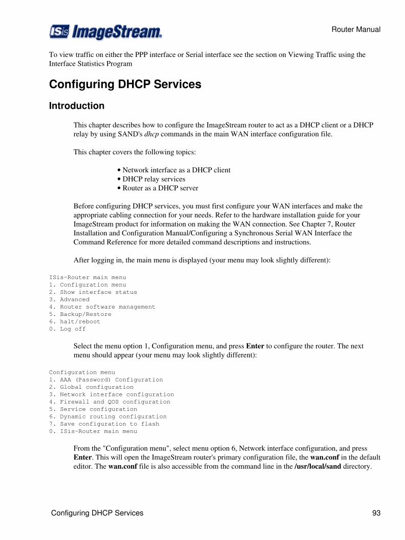
To view traffic on either the PPP interface or Serial interface see the section on Viewing Traffic using theInterface Statistics Program
Configuring DHCP Services
Introduction
This chapter describes how to configure the ImageStream router to act as a DHCP client or a DHCPrelay by using SAND's dhcp commands in the main WAN interface configuration file.
This chapter covers the following topics:
Network interface as a DHCP client• DHCP relay services• Router as a DHCP server•
Before configuring DHCP services, you must first configure your WAN interfaces and make theappropriate cabling connection for your needs. Refer to the hardware installation guide for yourImageStream product for information on making the WAN connection. See Chapter 7, RouterInstallation and Configuration Manual/Configuring a Synchronous Serial WAN Interface theCommand Reference for more detailed command descriptions and instructions.
After logging in, the main menu is displayed (your menu may look slightly different):
ISis-Router main menu 1. Configuration menu 2. Show interface status 3. Advanced 4. Router software management 5. Backup/Restore 6. halt/reboot 0. Log off
Select the menu option 1, Configuration menu, and press Enter to configure the router. The nextmenu should appear (your menu may look slightly different):
Configuration menu 1. AAA (Password) Configuration 2. Global configuration 3. Network interface configuration 4. Firewall and QOS configuration 5. Service configuration 6. Dynamic routing configuration 7. Save configuration to flash 0. ISis-Router main menu
From the "Configuration menu", select menu option 6, Network interface configuration, and pressEnter. This will open the ImageStream router's primary configuration file, the wan.conf in the defaulteditor. The wan.conf file is also accessible from the command line in the /usr/local/sand directory.
Router Manual
Configuring DHCP Services 93
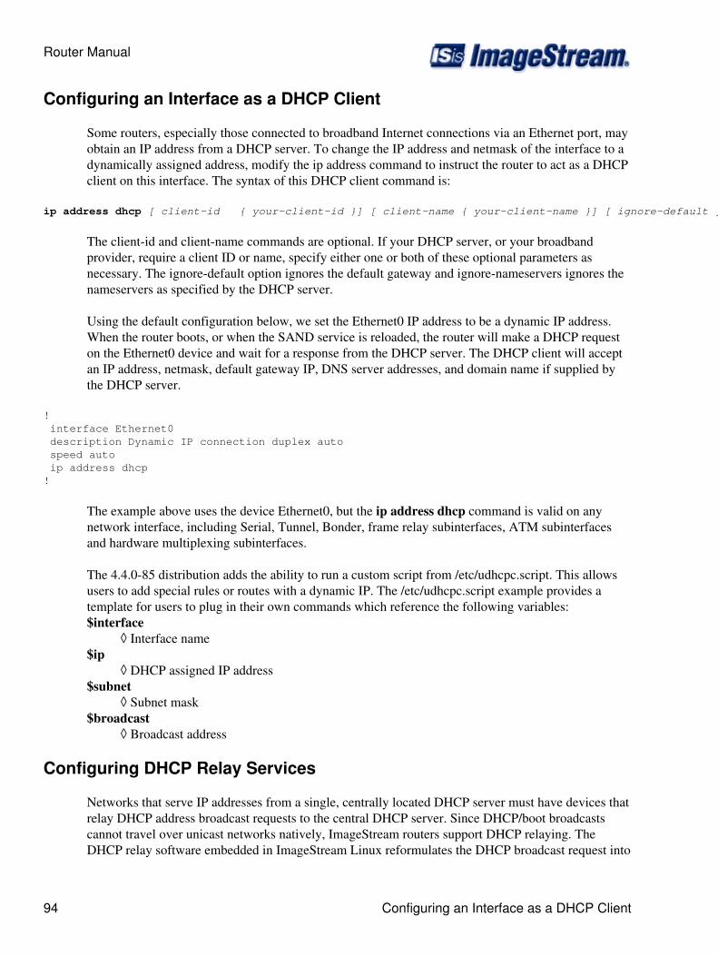
Configuring an Interface as a DHCP Client
Some routers, especially those connected to broadband Internet connections via an Ethernet port, mayobtain an IP address from a DHCP server. To change the IP address and netmask of the interface to adynamically assigned address, modify the ip address command to instruct the router to act as a DHCPclient on this interface. The syntax of this DHCP client command is:
ip address dhcp [ client-id { your-client-id }] [ client-name { your-client-name }] [ ignore-default ] [ ignore-nameservers ]
The client-id and client-name commands are optional. If your DHCP server, or your broadbandprovider, require a client ID or name, specify either one or both of these optional parameters asnecessary. The ignore-default option ignores the default gateway and ignore-nameservers ignores thenameservers as specified by the DHCP server.
Using the default configuration below, we set the Ethernet0 IP address to be a dynamic IP address.When the router boots, or when the SAND service is reloaded, the router will make a DHCP requeston the Ethernet0 device and wait for a response from the DHCP server. The DHCP client will acceptan IP address, netmask, default gateway IP, DNS server addresses, and domain name if supplied bythe DHCP server.
! interface Ethernet0 description Dynamic IP connection duplex auto speed auto ip address dhcp!
The example above uses the device Ethernet0, but the ip address dhcp command is valid on anynetwork interface, including Serial, Tunnel, Bonder, frame relay subinterfaces, ATM subinterfacesand hardware multiplexing subinterfaces.
The 4.4.0-85 distribution adds the ability to run a custom script from /etc/udhcpc.script. This allowsusers to add special rules or routes with a dynamic IP. The /etc/udhcpc.script example provides atemplate for users to plug in their own commands which reference the following variables:$interface
Interface name◊ $ip
DHCP assigned IP address◊ $subnet
Subnet mask◊ $broadcast
Broadcast address◊
Configuring DHCP Relay Services
Networks that serve IP addresses from a single, centrally located DHCP server must have devices thatrelay DHCP address broadcast requests to the central DHCP server. Since DHCP/boot broadcastscannot travel over unicast networks natively, ImageStream routers support DHCP relaying. TheDHCP relay software embedded in ImageStream Linux reformulates the DHCP broadcast request into
Router Manual
94 Configuring an Interface as a DHCP Client
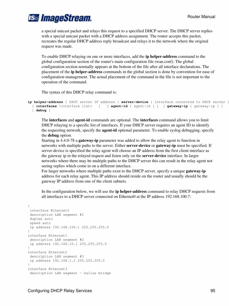
a special unicast packet and relays this request to a specified DHCP server. The DHCP server replieswith a special unicast packet with a DHCP address assignment. The router accepts this packet,recreates the regular DHCP address reply broadcast and relays it to the network where the originalrequest was made.
To enable DHCP relaying on one or more interfaces, add the ip helper-address command to theglobal configuration section of the router's main configuration file (wan.conf). The globalconfiguration section normally appears at the bottom of the file after all interface declarations. Theplacement of the ip helper-address commands in the global section is done by convention for ease ofconfiguration management. The actual placement of the command in the file is not important to theoperation of the command.
The syntax of this DHCP relay command is:
ip helper-address { DHCP server IP address } server-device { interface connected to DHCP server } [ interfaces <interface list> ] [ agent-id { agent-id } ] [ gateway-ip { gateway-ip } ] [ debug ]
The interfaces and agent-id commands are optional. The interfaces command allows you to limitDHCP relaying to a specific list of interfaces. If your DHCP server requires an agent ID to identifythe requesting network, specify the agent-id optional parameter. To enable syslog debugging, specifythe debug option.Starting in 4.4.0-78 a gateway-ip parameter was added to allow the relay agent to function innetworks with multiple paths to the server. Either server-device or gateway-ip must be specified. Ifserver-device is specified the relay agent will choose an IP address from the first client interface asthe gateway ip in the relayed request and listen only on the server-device interface. In largernetworks where there may be multiple paths to the DHCP server this can result in the relay agent notseeing replies which come in on a different interface.For larger networks where multiple paths exist to the DHCP server, specify a unique gateway-ipaddress for each relay agent. This IP address should reside on the router and usually should be thegateway IP address from one of the client subnets.
In the configuration below, we will use the ip helper-address command to relay DHCP requests fromall interfaces to a DHCP server connected on Ethernet0 at the IP address 192.168.100.7:
! interface Ethernet0 description LAN segment #1 duplex auto speed auto ip address 192.168.100.1 255.255.255.0!interface Ethernet1 description LAN segment #2 ip address 192.168.10.1 255.255.255.0!interface Ethernet2 description LAN segment #3 ip address 192.168.1.1 255.255.255.0!interface Ethernet3 description LAN segment - Dallas bridge
Router Manual
Configuring DHCP Relay Services 95
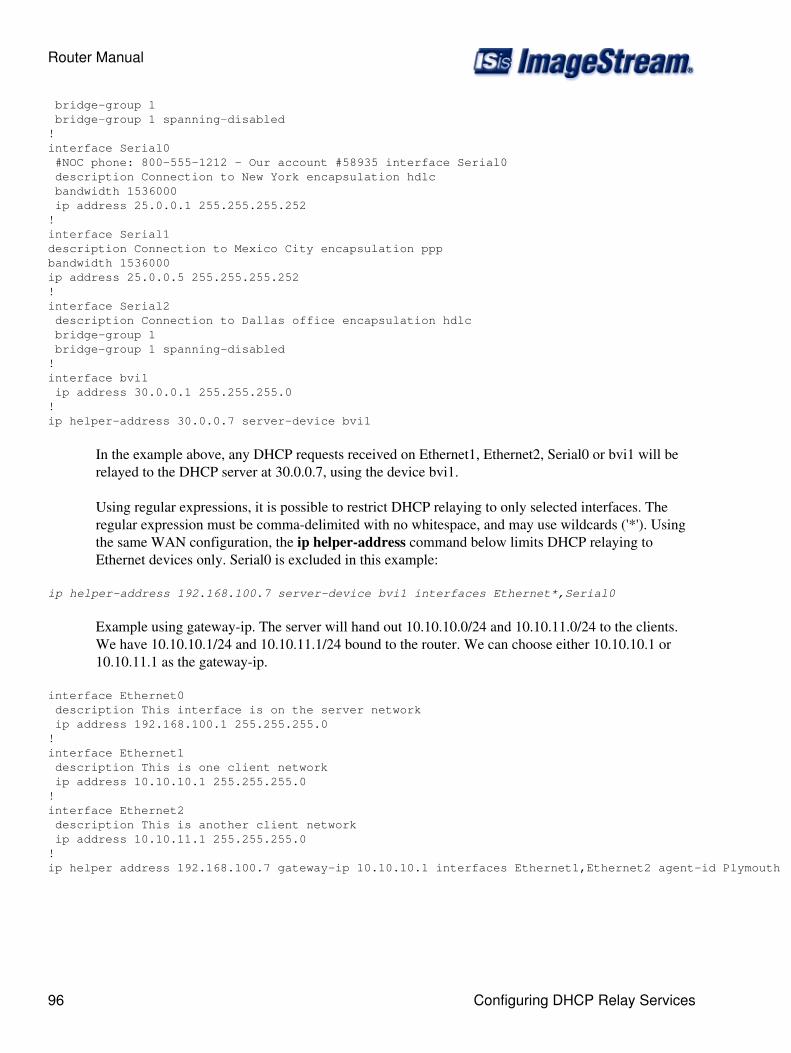
bridge-group 1 bridge-group 1 spanning-disabled!interface Serial0 #NOC phone: 800-555-1212 - Our account #58935 interface Serial0 description Connection to New York encapsulation hdlc bandwidth 1536000 ip address 25.0.0.1 255.255.255.252 ! interface Serial1 description Connection to Mexico City encapsulation ppp bandwidth 1536000 ip address 25.0.0.5 255.255.255.252!interface Serial2 description Connection to Dallas office encapsulation hdlc bridge-group 1 bridge-group 1 spanning-disabled!interface bvi1 ip address 30.0.0.1 255.255.255.0!ip helper-address 30.0.0.7 server-device bvi1
In the example above, any DHCP requests received on Ethernet1, Ethernet2, Serial0 or bvi1 will berelayed to the DHCP server at 30.0.0.7, using the device bvi1.
Using regular expressions, it is possible to restrict DHCP relaying to only selected interfaces. Theregular expression must be comma-delimited with no whitespace, and may use wildcards ('*'). Usingthe same WAN configuration, the ip helper-address command below limits DHCP relaying toEthernet devices only. Serial0 is excluded in this example:
ip helper-address 192.168.100.7 server-device bvi1 interfaces Ethernet*,Serial0
Example using gateway-ip. The server will hand out 10.10.10.0/24 and 10.10.11.0/24 to the clients.We have 10.10.10.1/24 and 10.10.11.1/24 bound to the router. We can choose either 10.10.10.1 or10.10.11.1 as the gateway-ip.
interface Ethernet0 description This interface is on the server network ip address 192.168.100.1 255.255.255.0!interface Ethernet1 description This is one client network ip address 10.10.10.1 255.255.255.0!interface Ethernet2 description This is another client network ip address 10.10.11.1 255.255.255.0!ip helper address 192.168.100.7 gateway-ip 10.10.10.1 interfaces Ethernet1,Ethernet2 agent-id Plymouth
Router Manual
96 Configuring DHCP Relay Services
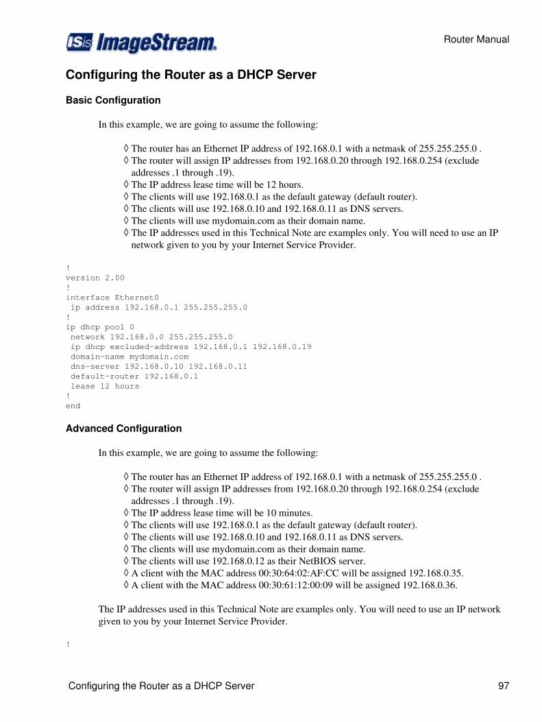
Configuring the Router as a DHCP Server
Basic Configuration
In this example, we are going to assume the following:
The router has an Ethernet IP address of 192.168.0.1 with a netmask of 255.255.255.0 .◊ The router will assign IP addresses from 192.168.0.20 through 192.168.0.254 (excludeaddresses .1 through .19).
◊
The IP address lease time will be 12 hours.◊ The clients will use 192.168.0.1 as the default gateway (default router).◊ The clients will use 192.168.0.10 and 192.168.0.11 as DNS servers.◊ The clients will use mydomain.com as their domain name.◊ The IP addresses used in this Technical Note are examples only. You will need to use an IPnetwork given to you by your Internet Service Provider.
◊
!version 2.00!interface Ethernet0 ip address 192.168.0.1 255.255.255.0!ip dhcp pool 0 network 192.168.0.0 255.255.255.0 ip dhcp excluded-address 192.168.0.1 192.168.0.19 domain-name mydomain.com dns-server 192.168.0.10 192.168.0.11 default-router 192.168.0.1 lease 12 hours! end
Advanced Configuration
In this example, we are going to assume the following:
The router has an Ethernet IP address of 192.168.0.1 with a netmask of 255.255.255.0 .◊ The router will assign IP addresses from 192.168.0.20 through 192.168.0.254 (excludeaddresses .1 through .19).
◊
The IP address lease time will be 10 minutes.◊ The clients will use 192.168.0.1 as the default gateway (default router).◊ The clients will use 192.168.0.10 and 192.168.0.11 as DNS servers.◊ The clients will use mydomain.com as their domain name.◊ The clients will use 192.168.0.12 as their NetBIOS server.◊ A client with the MAC address 00:30:64:02:AF:CC will be assigned 192.168.0.35.◊ A client with the MAC address 00:30:61:12:00:09 will be assigned 192.168.0.36.◊
The IP addresses used in this Technical Note are examples only. You will need to use an IP networkgiven to you by your Internet Service Provider.
!
Router Manual
Configuring the Router as a DHCP Server 97
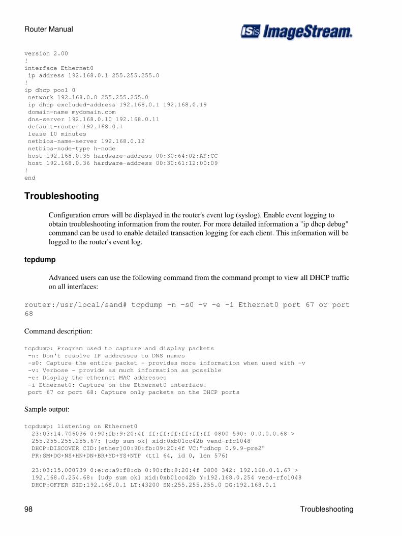
version 2.00!interface Ethernet0 ip address 192.168.0.1 255.255.255.0!ip dhcp pool 0 network 192.168.0.0 255.255.255.0 ip dhcp excluded-address 192.168.0.1 192.168.0.19 domain-name mydomain.com dns-server 192.168.0.10 192.168.0.11 default-router 192.168.0.1 lease 10 minutes netbios-name-server 192.168.0.12 netbios-node-type h-node host 192.168.0.35 hardware-address 00:30:64:02:AF:CC host 192.168.0.36 hardware-address 00:30:61:12:00:09! end
Troubleshooting
Configuration errors will be displayed in the router's event log (syslog). Enable event logging toobtain troubleshooting information from the router. For more detailed information a "ip dhcp debug"command can be used to enable detailed transaction logging for each client. This information will belogged to the router's event log.
tcpdump
Advanced users can use the following command from the command prompt to view all DHCP trafficon all interfaces:
router:/usr/local/sand# tcpdump -n -s0 -v -e -i Ethernet0 port 67 or port68
Command description:
tcpdump: Program used to capture and display packets -n: Don't resolve IP addresses to DNS names -s0: Capture the entire packet - provides more information when used with -v -v: Verbose - provide as much information as possible -e: Display the ethernet MAC addresses -i Ethernet0: Capture on the Ethernet0 interface. port 67 or port 68: Capture only packets on the DHCP ports
Sample output:
tcpdump: listening on Ethernet0 23:03:14.706036 0:90:fb:9:20:4f ff:ff:ff:ff:ff:ff 0800 590: 0.0.0.0.68 > 255.255.255.255.67: [udp sum ok] xid:0xb01cc42b vend-rfc1048 DHCP:DISCOVER CID:[ether]00:90:fb:09:20:4f VC:"udhcp 0.9.9-pre2" PR:SM+DG+NS+HN+DN+BR+YD+YS+NTP (ttl 64, id 0, len 576)
23:03:15.000739 0:e:c:a9:f8:cb 0:90:fb:9:20:4f 0800 342: 192.168.0.1.67 > 192.168.0.254.68: [udp sum ok] xid:0xb01cc42b Y:192.168.0.254 vend-rfc1048 DHCP:OFFER SID:192.168.0.1 LT:43200 SM:255.255.255.0 DG:192.168.0.1
Router Manual
98 Troubleshooting

NS:192.168.0.10,192.168.0.11 DN:"mydomain.com" [tos 0x10] (ttl 16, id 0, len 328)
23:03:15.001078 0:90:fb:9:20:4f ff:ff:ff:ff:ff:ff 0800 590: 0.0.0.0.68 > 255.255.255.255.67: [udp sum ok] xid:0xb01cc42b vend-rfc1048 DHCP:REQUEST CID:[ether]00:90:fb:09:20:4f VC:"udhcp 0.9.9-pre2" RQ:192.168.0.254 SID:192.168.0.1 PR:SM+DG+NS+HN+DN+BR+YD+YS+NTP (ttl 64, id 0, len 576)
23:03:15.001244 0:e:c:a9:f8:cb 0:90:fb:9:20:4f 0800 342: 192.168.0.1.67 > 192.168.0.254.68: [udp sum ok] xid:0xb01cc42b Y:192.168.0.254 vend-rfc1048 DHCP:ACK SID:192.168.0.1 LT:43200 SM:255.255.255.0 DG:192.168.0.1 NS:192.168.0.10,192.168.0.11 DN:"mydomain.com" [tos 0x10] (ttl 16, id 0, len 328)
Configuring Bonder for Load Balancing and Aggregation
This chapter describes how to configure the ImageStream router to use SAND's Bonder commands toload balance traffic across multiple circuits by aggregating multiple WAN devices. The Bondercommands are used to add aggregated devices on an interface-by-interface basis and to create theBonder interface in the main WAN interface configuration file.
This chapter includes the following topics:
Configuring Load Balancing and Aggregation using Bonder◊ Valid interfaces for the bond command◊
Before configuring Bonder devices, you must configure your WAN interfaces and make theappropriate cabling connection for your needs. Refer to the hardware installation guide for yourImageStream product for information on making the WAN connection. See the Command Referencefor more detailed command descriptions and instructions.
After logging in, the main menu is displayed (your menu may look slightly different):
ISis-Router main menu 1. Configuration menu 2. Show interface status 3. Advanced 4. Router software management 5. Backup/Restore 6. halt/reboot 0. Log off
Select menu option 1, Configuration menu, and press Enter to configure the router. TheConfiguration menu should appear (your menu may look slightly different):
Configuration menu 1. AAA (Password) Configuration 2. Global configuration 3. Network interface configuration 4. Firewall and QOS configuration 5. Service configuration 6. Dynamic routing configuration 7. Save configuration to flash
Router Manual
Configuring Bonder for Load Balancing and Aggregation 99
0. ISis-Router main menu
From the "Configuration menu", select menu option 3, Network interface configuration, and pressEnter. This will open the ImageStream router's primary configuration file, wan.conf in the defaulteditor. The wan.conf file is also accessible from the command line in the /usr/local/sand directory.
Configuring Load Balancing and Aggregation Using Bonder
The Bonder interface for SAND devices allows multiple interfaces or subinterfaces to be treated as asingle logical interface. A Bonder device is a standard network device and may be configured in thesame manner as all physical devices and subinterfaces. This link aggregation/load balancing softwareis compatible with most similar tools on other manufacturer's routers. To use the bonder, all of theserial devices that you want to aggregate must have the same endpoint.
A Bonder device can:
aggregate multiple physical devices into a single logical device◊ aggregate physical devices of different speeds (i.e. T1 and DS3)◊ aggregate frame relay and ATM subinterfaces◊ aggregate subinterfaces with physical devices (i.e. 256K ATM VC and T1)◊ provide automatic, zero-downtime failover for multiple WAN devices interoperate with aCisco router running per-packet CEF
◊
Aggregated links are controlled by a virtual Bonder interface configured in the interfaceconfiguration file. The interface is configured similarly to a Serial WAN interface. For this example,we will use this configuration showing a point-to-point T1 and a frame relay PVC:
! interface Serial0 description Leased line to Mexico City encapsulation hdlc ip address 25.0.0.1 255.255.255.255!interface Serial1 encapsulation frame-relay ietf bandwidth 1536000 frame-relay lmi-type ansi frame-relay interval 10 ! interface Serial1.1 description Frame to Mexico City encapsulation frame-relay ietf frame-relay interface-dlci 16 ip address 25.0.0.1 255.255.255.255 !
In the example below, we will bond Serial0 and Serial1.1 together. For the link aggregation tofunction, both Serial0 and Serial1.1 must terminate on the same remote router. The syntax of theBonder interface command is:
interface Bonder XX
Router Manual
100 Configuring Load Balancing and Aggregation Using Bonder
where XX is a device number. The location of a Bonder interface declaration in the interfaceconfiguration file is not important. By convention, the first Bonder device is Bonder0, though youmay assign any number. You do not need to specify an encapsulation type or bandwidth, as bothwill be ignored. You must specify an ip address. A description field is optional. To connect theSerial interfaces to the Bonder device that you have created, use the bond keyword. The syntax of thebond keyword is:
bond Device Name
In the example below, we have bonded the two Serial devices from above:
! interface Bonder0 description Bonded T1s to Mexico City bond Serial0 bond Serial1.1 ip address 192.168.10.1 255.255.255.252 !
The Bonder interface appears as a regular interface in the router, meaning you can makemodifications to the Bonder device configuration without taking down other interfaces. You can usefirewalling, bandwidth limiting, rule-based routing and other advanced features of the router with anyBonder device you create. Like other interfaces, the Bonder device is also available via SNMP formonitoring purposes.
The IP addresses on the individual T1s added to the bonded device using the bond keyword can be setto any valid IP address, and do not necessarily need to be identical. In the example above, both Serialinterfaces used the same IP address. If you choose to use the same IP address on all of the bondedinterfaces, you must use a host netmask (/32 or 255.255.255.255) on the individual serial devices.
Bonder distributes the load evenly based on each interface's bandwidth and the number of packetscurrently queued to that particular device. For example, a DS3 link bonded with a T1 line will sendmore traffic to the DS3 and will efficiently use the available bandwidth on both interfaces. Bonderautomatically calculates bandwidth based on the active bonded interfaces and will not attempt to useany interface which has hardware or protocol down.
Valid Interfaces for the Bond Command
The bond command can only be used in conjunction with a Bonder device. You may only bondSAND interfaces. You cannot bond the following:
Ethernet interfaces◊ Token ring interfaces◊ Tunnel interfaces◊ VPN interfaces◊ VLAN interfaces◊
Note: You must save the settings to the router's non-volatile flash memory! If the router isrebooted before saving, your changes will be lost! See Chapter 26, "Backup/Restore Menu:Managing Configurations" for more information.
Router Manual
Valid Interfaces for the Bond Command 101

Configuring Multilink PPP for Load Balancing andAggregation
Introduction
This chapter describes how to configure the ImageStream router to use the Inetics Multilink PPPcommands to load balance traffic across multiple circuits by aggregating multiple WAN devices. TheMultilink commands are used to add aggregated devices on an interface-by-interface basis and tocreate the Multilink interfaces in the main WAN interface configuration file.
This chapter includes the following topics:
Configuring Load Balancing and Aggregation using Multilink PPP◊ Valid interfaces for Multilink devices◊
Before configuring Multilink PPP devices, you must configure your WAN interfaces and make theappropriate cabling connection for your needs. Refer to the hardware installation guide for yourImageStream product for information on making the WAN connection. See Chapter 7, RouterInstallation and Configuration Manual/Configuring a Synchronous Serial WAN Interface or theCommand Reference for more detailed command descriptions and instructions.
After logging in, the main menu is displayed (your menu may look slightly different):
ISis-Router main menu 1. Configuration menu 2. Show interface status 3. Advanced 4. Router software management 5. Backup/Restore 6. halt/reboot 0. Log off
Select menu option 1, Configuration menu, and press Enter to configure the router. TheConfiguration menu should appear (your menu may look slightly different):
Configuration menu 1. AAA (Password) Configuration 2. Global configuration 3. Network interface configuration 4. Firewall and QOS configuration 5. Service configuration 6. Dynamic routing configuration 7. Save configuration to flash 0. ISis-Router main menu
From the "Configuration menu", select menu option 3, Network interface configuration, and pressEnter. This will open the ImageStream router's primary configuration file, wan.conf in the defaulteditor. The wan.conf file is also accessible from the command line in the /usr/local/sand directory.
Router Manual
102 Configuring Multilink PPP for Load Balancing and Aggregation
Configuring Load Balancing and Aggregation using Multilink PPP
"The Multilink interface for SAND devices allows multiple PPP encapsulated interfaces to be treatedas a single logical interface. A Multilink device is a standard network device and may be configuredin the same manner as all physical devices and subinterfaces. This link aggregation/load balancingsoftware is compatible with Multilink PPP implementations on other manufacturer's routers. To usemultilink PPP, all of the serial devices that you want to aggregate must run the PPP encapsulation,have the same endpoint and have MPPP configured on the remote router.
A Multilink device can:
aggregate multiple physical devices into a single logical device◊ aggregate physical devices of different speeds (i.e. T1 and DS3)◊ provide automatic, zero-downtime failover for multiple WAN devices interoperate with aCisco router running MPPP
◊
For compatibility with Cisco routers, the Cisco configuration must include the "ppp multilinkinterleave" command.
Aggregated links are controlled by a virtual Multilink interface configured in the interfaceconfiguration file. The interface is configured similarly to a Serial WAN interface. For this example,we will use this configuration showing two point-to-point T1 lines running PPP:
! interface Serial0 description Leased line to Mexico City encapsulation ppp ip address 25.0.0.1 255.255.255.252!interface Serial1 #NOC phone: 800-555-1212 - Our account #58935 interface Serial1 description Leased line to Mexico City encapsulation ppp ip address 25.0.0.5 255.255.255.252!
In following example, we will bond Serial0 and Serial1 together. For the link aggregation to function,both Serial0 and Serial1 must terminate on the same remote router and the remote router must haveMPPP configured.
The syntax of the Multilink interface command is:
interface Multilink XX
where XX is a device number. The location of a Multilink interface declaration in the interfaceconfiguration file is not important. By convention, the first Multilink device is Multilink0, though youmay assign any number. You do not need to specify an encapsulation type or bandwidth, as both willbe ignored. You must specify an ip address. A description field is optional.
In the example below, we have created a Multilink0 interface:
Router Manual
Configuring Load Balancing and Aggregation using Multilink PPP 103
! interface Multilink0 description MPPP Port ip address 216.146.78.1 255.255.255.252 !
To connect the Serial interfaces to the Multilink device that you have created, you must add twocommands to each Serial interface. Use the ppp multilink keyword to indicate that the interface ispart of a multilink PPP group. The syntax of the ppp multilink keyword is:
ppp multilink
The command accepts no parameters. To add the Serial device to the specific Multilink interfacecreated in the previous step, use the multilink-group command.
The syntax of the ppp multilink keyword is:
multilink-group XX
where XX is the device number you used when creating the Multilink interface. Using the originalSerial interfaces and Multilink interface from above, the configuration below creates a multilink PPPgroup from the two individual PPP interfaces:
! interface Serial0 description Leased line to Mexico Cityencapsulation ppp ppp multilink multilink-group 0 ip address 25.0.0.1 255.255.255.252!#NOC phone: 800-555-1212 - Our account #58935 interface Serial1 description Leased line to Mexico Cityencapsulation ppp ppp multilink multilink-group 0 ip address 25.0.0.5 255.255.255.252!interface Multilink0description MPPP Portip address 216.146.78.1 255.255.255.252!
The Multilink interface appears as a regular interface in the router, meaning you can makemodifications to the Multilink device configuration without taking down other interfaces. You can usefirewalling, bandwidth limiting, rule-based routing and other advanced features of the router with anyMultilink device you create. Like other interfaces, the bonder device is also available via SNMP formonitoring purposes.
The IP addresses on the individual T1s added to the Multilink device can be set to any valid IPaddress, and do not necessarily need to be identical. If you choose to use the same IP address on all ofthe individual PPP interfaces, you must use a host netmask (/32 or 255.255.255.255) on these devices.
Router Manual
104 Configuring Load Balancing and Aggregation using Multilink PPP
Multilink PPP distributes the load evenly by fragmenting packets and sending the packet fragmentsdown each T1 line before reassembling the packets at the remote end. Multilink interfacesautomatically calculate bandwidth based on the active PPP interfaces in the group and will notattempt to use any interface which has hardware or protocol down.
Valid Interfaces for the Multilink device
The ppp multilink and multilink-group commands can only be used in conjunction with aMultilink device. You may only add SAND interfaces running PPP to Multilink devices.
Note: You must save the settings to the router's non-volatile flash memory! If the router isrebooted before saving, your changes will be lost! See Chapter 26, "Backup/Restore Menu:Managing Configurations" for more information.
Configuring Multilink Frame for Load Balancing andAggregation
--- This page is currently under construction ---
Configuring Bridging
bridge-group (bridge group) - Adds the interface to the bridge group
New bridge-group commands include: ex: bridge-group 16 spanning-disabled
spanning-disabled - Disables the spanning tree algorithm for the bridge group
priority (prio) - Sets the bridge port priority for this interface
path-cost (cost) - Set the port's path cost (values 1-65535)
New bridge commands (global bridge configuration) ex: bridge 16 aging-time 300
spanning-disabled - Disables the spanning tree algorithm for the bridge
priority (prio) - Sets the bridge priority
path-cost (cost) - Set the bridge's path cost (values 1-65535)
aging-time (seconds) - Sets the bridge's aging time (values 1-1000000)
forward-time (seconds) - Sets the bridge's forwarding time (values 1-200)
hello-time (seconds) - Sets the bridge's hello time (values 1-10)
max-age (seconds) - Sets the bridge's maximum aging time (values 10-200)
Router Manual
Valid Interfaces for the Multilink device 105
Each bridge group automatically provides an interface to allow configuring IPs and routing for the bridge. Theinterface will be named bvi(bridge group). So if you have a bridge-group 16 you'll be able to configureinterface bvi16.
Here's a quick example:
interface Serial0 description SuperLine Shelf encapsulation frame-relay ietf frame-relay mode dce!interface Serial0.16 description DLCI 16 (10.10.16.0) frame-relay interface-dlci 16 bridge-group 16!interface Serial0.17 description DLCI 17 (10.10.17.0) frame-relay interface-dlci 17 bridge-group 17!interface Serial0.18 description DLCI 18 (10.10.18.0) frame-relay interface-dlci 18 bridge-group 18 spanning-disabled!interface bvi16 ip address 10.10.16.1 255.255.255.0!interface bvi17 ip address 10.10.17.1 255.255.255.0!interface bvi18 ip address 10.10.18.1 255.255.255.0!# Change the forwarding delay to 3 secondsbridge 16 forward-time 3# Change the hello interval to 10 secondsbridge 16 hello-time 10
Configuring IP Tunnels
This chapter describes how to configure the ImageStream router to use the Inetics Tunnel interface tocreate encrypted and unencrypted tunnels across physical devices.
This chapter includes the following topics:
Understanding Tunnel Devices◊ Configuring SSL Tunnels using OpenVPN◊ Configuring CIPE Tunnel Devices◊ Configuring GRE Tunnel Devices◊
Router Manual
106 Configuring Bridging
Understanding Tunnel Devices
Tunneling provides a way to encapsulate packets of a foreign protocol or network inside a transportprotocol. Tunneling is implemented as a virtual interface to provide a simple interface forconfiguration. A tunnel interface is not tied to specific protocols, devices or network transports.Tunnels provide an architecture that is designed to support any standard point-to-point encapsulationscheme. Because tunnels are point-to-point links, you must configure a separate tunnel for each link.
Tunnel devices can encapsulate a wide variety of protocol packet types inside IP tunnels, creating avirtual point-to-point link to routers at remote points over an IP internetwork. The Tunnel commandsare used to create the Tunnel interface in the main WAN interface configuration file.
Before configuring Tunnel devices, you must configure your WAN interfaces and make theappropriate cabling connection for your needs. Refer to the hardware installation guide for yourImageStream product for information on making the WAN connection. See Chapter 7, RouterInstallation and Configuration Manual/Configuring a Synchronous Serial WAN Interface or theCommand Reference for more detailed command descriptions and instructions.
After logging in, the main menu is displayed (your menu may look slightly different):
ISis-Router main menu 1. Configuration menu 2. Show interface status 3. Advanced 4. Router software management 5. Backup/Restore 6. halt/reboot 0. Log off
Select menu option 1, Configuration menu, and press Enter to configure the router. TheConfiguration menu should appear (your menu may look slightly different):
Configuration menu 1. AAA (Password) Configuration 2. Global configuration 3. Network interface configuration 4. Firewall and QOS configuration 5. Service configuration 6. Dynamic routing configuration 7. Save configuration to flash 0. ISis-Router main menu
From the "Configuration menu", select menu option 3, Network interface configuration, and pressEnter. This will open the ImageStream router's primary configuration file, wan.conf, in the defaulteditor. The wan.conf file is also accessible from the command line in the /usr/local/sand directory.
Configuring a Simple SSL Tunnel using OPENVPN
The SSL tunnel interface mode for Inetics devices uses the OpenVPN suite and allows IP packettunneling inside encrypted UDP or TCP packets. The protocol is designed to be lightweight andsimple, and to work seamlessly with dynamic addresses, NAT and SOCKS proxies. An OpenVPN
Router Manual
Understanding Tunnel Devices 107
tunnel device is a standard network device and may be configured in the same manner as all physicaldevices and subinterfaces.
If your configuration requires dynamic routing (BGP, OSPF, RIP) or metric-based static routingfailover configurations, you should use the OpenVPN SSL tunnels. Unlike CIPE tunnels or othertunnels supported by the ImageStream router, OpenVPN tunnels use the standard hardware andprotocol status functions and may be used with configurations that rely on interface status.
ImageStream Linux 4.2 or later releases provide support for OpenVPN tunnels. An ImageStreamrouter's OpenVPN implementation can interoperate with any OpenVPN client on any operatingsystem.
The configurations listed in this section may not be suitable for use on your network. Any devicenames, IP addresses, tunnel keys or bandwidth values are provided as examples. You will need tochange the commands in the examples below to match the settings suitable for your network.
In this example, we will create an encrypted tunnel between these two routers. The syntax of theTunnel interface command is:
interface Tunnel XX
where XX is a device number. The location of a Tunnel interface declaration in the interfaceconfiguration file is not important. By convention, the first Tunnel device is Tunnel0, though youmay assign any number. You do not need to specify an encapsulation type, as it will be ignored. Youmust specify an ip address. A description field is optional.
To configure each end of the point-to-point tunnel, you must configure the tunnel addresses, thetunnel source and destination, and the authentication key. The example below shows two localnetworks connected via an OpenVPN tunnel to form a VPN interconnecting the 172.16.0.0/16 and192.168.0.0/24 reserved network blocks. In the example below, 172.16.0.0/16 is the network at themain office and 192.168.0.0/24 is the network at a remote office.
Main Office Router:
! interface Tunnel0 description Tunnel to Remote Office bandwidth 768000 tunnel mode openvpn tunnel source 210.145.243.1 6061 tunnel destination 63.148.135.25 6061 tunnel key 8c34cdc8f4a2e1fb01dd5c0fdc9082e4 ip address 192.168.150.1 255.255.255.252 pointopoint address 192.168.150.2 ! ip route add 192.168.0.0/24 via 192.168.150.2
Remote Office Router:
! interface Tunnel0 description Tunnel to Remote Office bandwidth 768000
Router Manual
108 Configuring a Simple SSL Tunnel using OPENVPN

tunnel mode openvpn tunnel source 63.148.135.25 6061 tunnel destination 210.145.243.1 6061 tunnel key 8c34cdc8f4a2e1fb01dd5c0fdc9082e4 ip address 192.168.150.2 255.255.255.252 pointopoint address 192.168.150.1 ! ip route add 172.16.0.0/16 via 192.168.150.1
The values in the above example are explained below.
Interface Tunnel0 - Denotes the start of the configuration section for the first Tunnel device in yoursystem. All commands that follow this line until the next ! mark will be applied to Tunnel0.
description Tunnel to Remote Office - Sets a description for this device. The description is optionalused for reporting purposes in other utilities. Setting a value here does not affect the operation of theport.
bandwidth 768000 - Scales the output of the realtime statistics program to 768 Kbps. This value isoptional, and should be set either to the connected link speed or to the bandwidth limit allocated byQoS rules.
tunnel mode openvpn - Sets the encapsulation type on the tunnel to OpenVPN.
tunnel source 63.148.135.25 6061 - Sets the source address of the tunnel and the UDP or TCP portused to receive the SSL tunnel's encapsulated packets. The command takes the form tunnel sourceipaddress port. The IP address selected must be different from the ip address of the tunnel. The tunnelsource address should be an address reachable on the network by the destination router.
tunnel destination 210.145.243.1 6061 - Sets the destination address of the tunnel and the UDP orTCP port used to send the SSL tunnel's encapsulated packets. The command takes the form tunneldestination ipaddress port. The IP address and port must match the values configured as the source onthe destination router.
tunnel key 8c34cdc8f4a2e1fb01dd5c0fdc9082e4 - Sets the encryption key used by the tunnel. Thiscommand takes the form tunnel key key. This value must match the value configured on thedestination router. OpenVPN uses a 2048-bit key. If the key specified is less than 2048 bits, the routerwill automatically replicate the value until the size reaches 2048 bits.
ip address 192.168.150.1 255.255.255.252 - Specifies the IP address and netmask for the Tunneldevice. The IP addresses on the source and destination ends of the tunnel must be different from theIP address and pointtopoint address of the tunnel itself.
pointopoint address 192.168.150.2 - Specifies the remote tunnel address. This IP address mustmatch the value configured as the IP address on the destination router.
ip route add 192.168.0.0/24 via 192.168.150.2 - Adds a static route to the 192.168.0.0 networkthrough the Tunnel0 IP address on the main office router. Note that the command follows the Linuxiproute2 syntax. Cisco IOS-style syntax commands are also accepted, as described in earlier sections.
Router Manual
Configuring a Simple SSL Tunnel using OPENVPN 109
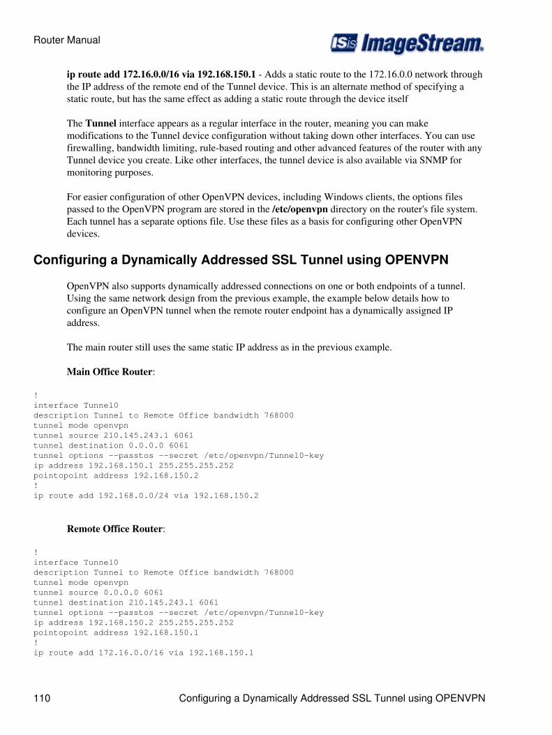
ip route add 172.16.0.0/16 via 192.168.150.1 - Adds a static route to the 172.16.0.0 network throughthe IP address of the remote end of the Tunnel device. This is an alternate method of specifying astatic route, but has the same effect as adding a static route through the device itself
The Tunnel interface appears as a regular interface in the router, meaning you can makemodifications to the Tunnel device configuration without taking down other interfaces. You can usefirewalling, bandwidth limiting, rule-based routing and other advanced features of the router with anyTunnel device you create. Like other interfaces, the tunnel device is also available via SNMP formonitoring purposes.
For easier configuration of other OpenVPN devices, including Windows clients, the options filespassed to the OpenVPN program are stored in the /etc/openvpn directory on the router's file system.Each tunnel has a separate options file. Use these files as a basis for configuring other OpenVPNdevices.
Configuring a Dynamically Addressed SSL Tunnel using OPENVPN
OpenVPN also supports dynamically addressed connections on one or both endpoints of a tunnel.Using the same network design from the previous example, the example below details how toconfigure an OpenVPN tunnel when the remote router endpoint has a dynamically assigned IPaddress.
The main router still uses the same static IP address as in the previous example.
Main Office Router:
! interface Tunnel0 description Tunnel to Remote Office bandwidth 768000 tunnel mode openvpn tunnel source 210.145.243.1 6061 tunnel destination 0.0.0.0 6061 tunnel options --passtos --secret /etc/openvpn/Tunnel0-key ip address 192.168.150.1 255.255.255.252 pointopoint address 192.168.150.2 ! ip route add 192.168.0.0/24 via 192.168.150.2
Remote Office Router:
! interface Tunnel0 description Tunnel to Remote Office bandwidth 768000 tunnel mode openvpn tunnel source 0.0.0.0 6061 tunnel destination 210.145.243.1 6061 tunnel options --passtos --secret /etc/openvpn/Tunnel0-key ip address 192.168.150.2 255.255.255.252 pointopoint address 192.168.150.1 ! ip route add 172.16.0.0/16 via 192.168.150.1
Router Manual
110 Configuring a Dynamically Addressed SSL Tunnel using OPENVPN
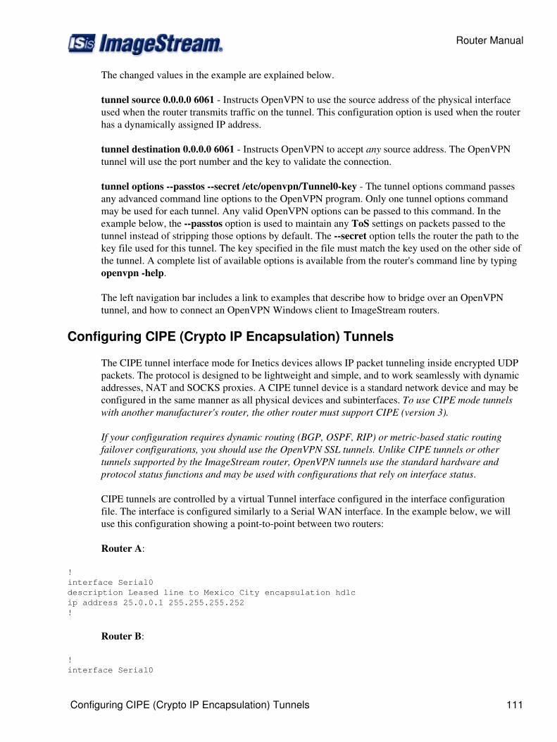
The changed values in the example are explained below.
tunnel source 0.0.0.0 6061 - Instructs OpenVPN to use the source address of the physical interfaceused when the router transmits traffic on the tunnel. This configuration option is used when the routerhas a dynamically assigned IP address.
tunnel destination 0.0.0.0 6061 - Instructs OpenVPN to accept any source address. The OpenVPNtunnel will use the port number and the key to validate the connection.
tunnel options --passtos --secret /etc/openvpn/Tunnel0-key - The tunnel options command passesany advanced command line options to the OpenVPN program. Only one tunnel options commandmay be used for each tunnel. Any valid OpenVPN options can be passed to this command. In theexample below, the --passtos option is used to maintain any ToS settings on packets passed to thetunnel instead of stripping those options by default. The --secret option tells the router the path to thekey file used for this tunnel. The key specified in the file must match the key used on the other side ofthe tunnel. A complete list of available options is available from the router's command line by typingopenvpn -help.
The left navigation bar includes a link to examples that describe how to bridge over an OpenVPNtunnel, and how to connect an OpenVPN Windows client to ImageStream routers.
Configuring CIPE (Crypto IP Encapsulation) Tunnels
The CIPE tunnel interface mode for Inetics devices allows IP packet tunneling inside encrypted UDPpackets. The protocol is designed to be lightweight and simple, and to work seamlessly with dynamicaddresses, NAT and SOCKS proxies. A CIPE tunnel device is a standard network device and may beconfigured in the same manner as all physical devices and subinterfaces. To use CIPE mode tunnelswith another manufacturer's router, the other router must support CIPE (version 3).
If your configuration requires dynamic routing (BGP, OSPF, RIP) or metric-based static routingfailover configurations, you should use the OpenVPN SSL tunnels. Unlike CIPE tunnels or othertunnels supported by the ImageStream router, OpenVPN tunnels use the standard hardware andprotocol status functions and may be used with configurations that rely on interface status.
CIPE tunnels are controlled by a virtual Tunnel interface configured in the interface configurationfile. The interface is configured similarly to a Serial WAN interface. In the example below, we willuse this configuration showing a point-to-point between two routers:
Router A:
! interface Serial0 description Leased line to Mexico City encapsulation hdlc ip address 25.0.0.1 255.255.255.252!
Router B:
! interface Serial0
Router Manual
Configuring CIPE (Crypto IP Encapsulation) Tunnels 111

description Leased line to New York City encapsulation hdlc ip address 25.0.0.2 255.255.255.252!
In the following example, we will create an encrypted tunnel between these two routers. The syntax ofthe Tunnel interface command is:
interface Tunnel XX
where XX is a device number. The location of a Tunnel interface declaration in the interfaceconfiguration file is not important. By convention, the first Tunnel device is Tunnel0, though youmay assign any number. You do not need to specify an encapsulation type, as it will be ignored. Youmust specify an ip address. A description field is optional.
To configure each end of the point-to-point tunnel, you must configure the tunnel addresses, thetunnel source and destination, and the authentication key. The example below shows the tunnelconfiguration for a CIPE tunnel between Router A and Router B.
Router A:
! interface Serial0 description Leased line to Mexico City encapsulation hdlc ip address 25.0.0.1 255.255.255.252!interface Tunnel0 description VPN to Mexico City bandwidth 256000 tunnel mode cipe tunnel source 25.0.0.1 4451 tunnel destination 25.0.0.2 4451 tunnel key abcdef001 ip address 10.0.0.1 255.255.255.252 pointopoint address 10.0.0.2 ! ip route 192.168.100.0 255.255.255.0 Tunnel0
Router B:
! interface Serial0 description Leased line to New York City encapsulation hdlc ip address 25.0.0.2 255.255.255.252!interface Tunnel0 description VPN to New York City bandwidth 256000 tunnel mode cipe tunnel source 25.0.0.2 4451 tunnel destination 25.0.0.1 4451 tunnel key abcdef001 ip address 10.0.0.2 255.255.255.252 pointopoint address 10.0.0.2 ! ip route 192.168.10.0 255.255.255.0 10.0.0.1
Router Manual
112 Configuring CIPE (Crypto IP Encapsulation) Tunnels
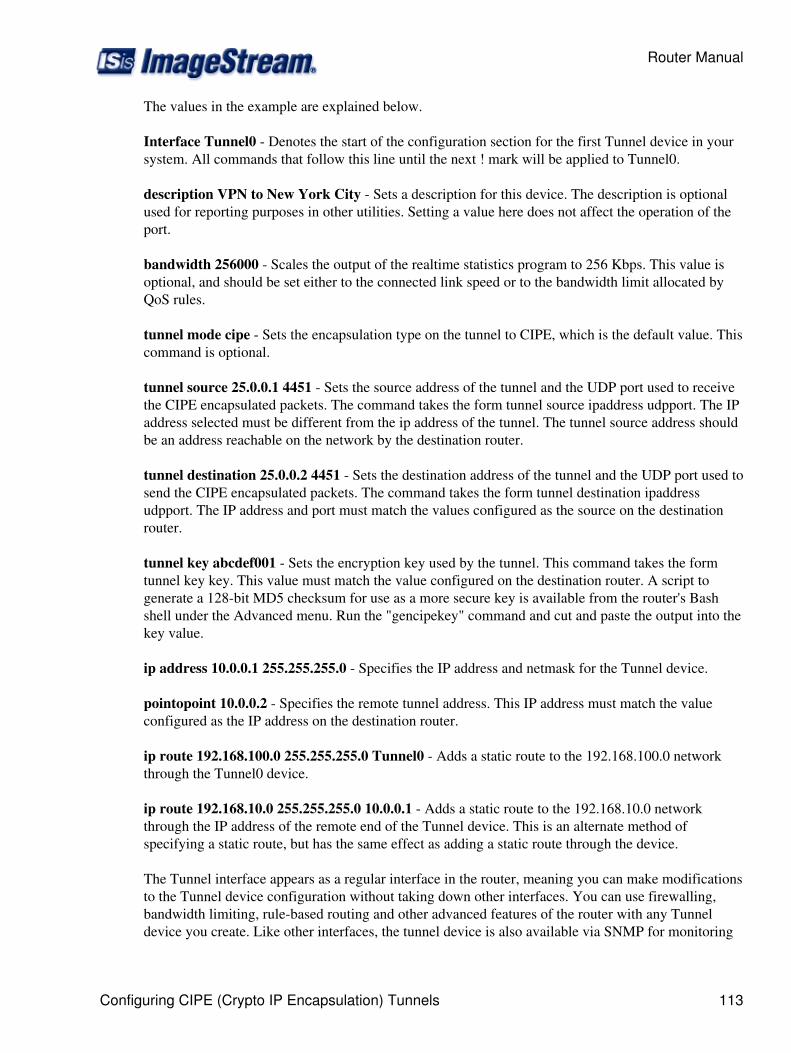
The values in the example are explained below.
Interface Tunnel0 - Denotes the start of the configuration section for the first Tunnel device in yoursystem. All commands that follow this line until the next ! mark will be applied to Tunnel0.
description VPN to New York City - Sets a description for this device. The description is optionalused for reporting purposes in other utilities. Setting a value here does not affect the operation of theport.
bandwidth 256000 - Scales the output of the realtime statistics program to 256 Kbps. This value isoptional, and should be set either to the connected link speed or to the bandwidth limit allocated byQoS rules.
tunnel mode cipe - Sets the encapsulation type on the tunnel to CIPE, which is the default value. Thiscommand is optional.
tunnel source 25.0.0.1 4451 - Sets the source address of the tunnel and the UDP port used to receivethe CIPE encapsulated packets. The command takes the form tunnel source ipaddress udpport. The IPaddress selected must be different from the ip address of the tunnel. The tunnel source address shouldbe an address reachable on the network by the destination router.
tunnel destination 25.0.0.2 4451 - Sets the destination address of the tunnel and the UDP port used tosend the CIPE encapsulated packets. The command takes the form tunnel destination ipaddressudpport. The IP address and port must match the values configured as the source on the destinationrouter.
tunnel key abcdef001 - Sets the encryption key used by the tunnel. This command takes the formtunnel key key. This value must match the value configured on the destination router. A script togenerate a 128-bit MD5 checksum for use as a more secure key is available from the router's Bashshell under the Advanced menu. Run the "gencipekey" command and cut and paste the output into thekey value.
ip address 10.0.0.1 255.255.255.0 - Specifies the IP address and netmask for the Tunnel device.
pointopoint 10.0.0.2 - Specifies the remote tunnel address. This IP address must match the valueconfigured as the IP address on the destination router.
ip route 192.168.100.0 255.255.255.0 Tunnel0 - Adds a static route to the 192.168.100.0 networkthrough the Tunnel0 device.
ip route 192.168.10.0 255.255.255.0 10.0.0.1 - Adds a static route to the 192.168.10.0 networkthrough the IP address of the remote end of the Tunnel device. This is an alternate method ofspecifying a static route, but has the same effect as adding a static route through the device.
The Tunnel interface appears as a regular interface in the router, meaning you can make modificationsto the Tunnel device configuration without taking down other interfaces. You can use firewalling,bandwidth limiting, rule-based routing and other advanced features of the router with any Tunneldevice you create. Like other interfaces, the tunnel device is also available via SNMP for monitoring
Router Manual
Configuring CIPE (Crypto IP Encapsulation) Tunnels 113

purposes.
The IP addresses on the source and destination ends of the tunnel must be different from the IPaddress and point-to-point address of the tunnel itself.
Configuring GRE Tunnels
The GRE tunnel interface allows for IP packet tunneling using the GRE protocol. The protocol isdesigned to be lightweight and simple.
ImageStream Linux 4.0 or later releases provide support for GRE tunnels. An ImageStream router'sGRE implementation can interoperate with any GRE client on any operating system.
The configurations listed in this section may not be suitable for use on your network. Any devicenames, IP addresses, tunnel keys or bandwidth values are provided as examples. You will need tochange the commands in the examples below to match the settings suitable for your network.
To configure each end of the point-to-point tunnel, you must configure the tunnel addresses, thetunnel source and destination. The example below shows the tunnel configuration for a GRE tunnelbetween Router A and Router B.
Router A:
! interface Serial0 description Leased line to Mexico City encapsulation hdlc ip address 25.0.0.1 255.255.255.252!interface Tunnel0 description VPN to Mexico City bandwidth 256000 tunnel mode gretunnel source 25.0.0.1 tunnel destination 25.0.0.2 ip address 10.0.0.1 255.255.255.252 ! ip route 192.168.100.0 255.255.255.0 Tunnel0
Router B:
! interface Serial0 description Leased line to New York City encapsulation hdlc ip address 25.0.0.2 255.255.255.252!interface Tunnel0 description VPN to New York City bandwidth 256000 tunnel mode gretunnel source 25.0.0.2tunnel destination 25.0.0.1ip address 10.0.0.2 255.255.255.252 ! ip route 192.168.10.0 255.255.255.0 10.0.0.1
Router Manual
114 Configuring GRE Tunnels
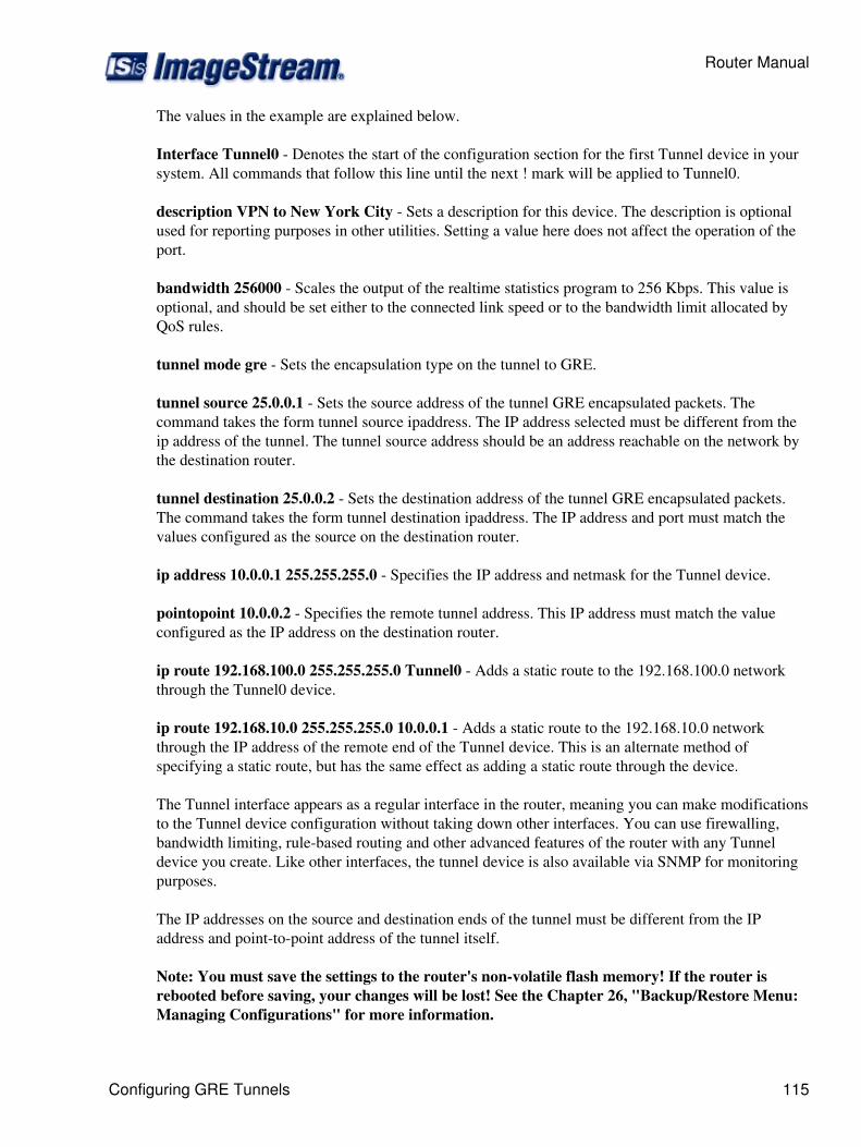
The values in the example are explained below.
Interface Tunnel0 - Denotes the start of the configuration section for the first Tunnel device in yoursystem. All commands that follow this line until the next ! mark will be applied to Tunnel0.
description VPN to New York City - Sets a description for this device. The description is optionalused for reporting purposes in other utilities. Setting a value here does not affect the operation of theport.
bandwidth 256000 - Scales the output of the realtime statistics program to 256 Kbps. This value isoptional, and should be set either to the connected link speed or to the bandwidth limit allocated byQoS rules.
tunnel mode gre - Sets the encapsulation type on the tunnel to GRE.
tunnel source 25.0.0.1 - Sets the source address of the tunnel GRE encapsulated packets. Thecommand takes the form tunnel source ipaddress. The IP address selected must be different from theip address of the tunnel. The tunnel source address should be an address reachable on the network bythe destination router.
tunnel destination 25.0.0.2 - Sets the destination address of the tunnel GRE encapsulated packets.The command takes the form tunnel destination ipaddress. The IP address and port must match thevalues configured as the source on the destination router.
ip address 10.0.0.1 255.255.255.0 - Specifies the IP address and netmask for the Tunnel device.
pointopoint 10.0.0.2 - Specifies the remote tunnel address. This IP address must match the valueconfigured as the IP address on the destination router.
ip route 192.168.100.0 255.255.255.0 Tunnel0 - Adds a static route to the 192.168.100.0 networkthrough the Tunnel0 device.
ip route 192.168.10.0 255.255.255.0 10.0.0.1 - Adds a static route to the 192.168.10.0 networkthrough the IP address of the remote end of the Tunnel device. This is an alternate method ofspecifying a static route, but has the same effect as adding a static route through the device.
The Tunnel interface appears as a regular interface in the router, meaning you can make modificationsto the Tunnel device configuration without taking down other interfaces. You can use firewalling,bandwidth limiting, rule-based routing and other advanced features of the router with any Tunneldevice you create. Like other interfaces, the tunnel device is also available via SNMP for monitoringpurposes.
The IP addresses on the source and destination ends of the tunnel must be different from the IPaddress and point-to-point address of the tunnel itself.
Note: You must save the settings to the router's non-volatile flash memory! If the router isrebooted before saving, your changes will be lost! See the Chapter 26, "Backup/Restore Menu:Managing Configurations" for more information.
Router Manual
Configuring GRE Tunnels 115

Configuring L2TP for LNS
L2TP tunnels client PPP sessions from the telco's LAC (access concentrator) to the ISP's LNS. L2TP uses aIP/UDP tunnel on port 1701 to encapsulate the PPP frames and tunnel them over an IP network. L2TP can betunneled across the internet if needed but most setups generally have the telco providing a dedicated GigEport or dedicated DS3/OC3 to each LNS cluster for carrying the L2TP sessions. Most of the larger setups use3 LNS routers per cluster with each LNS carrying between 2,000 to 3,000 customers. These 8,000 to 9,000customers will fully utilize the GigE port during peak times with each LNS sending about 350 Mbps towardthe customers.
For load balancing and redundancy the LAC normally is configured with a list of LNS IPs. Often LACs in acertain region will be configured to send to a particular cluster of LNS IPs. The LAC will round-robinbetween the LNS routers automatically as new client PPP sessions are established. If an LNS goes down allPPP sessions on that LNS will terminate or eventually time out and re-establish on other active LNSs in thecluster. The LAC (Cisco does but Juniper doesn't) will cache the status of previous LNS connection attempts.
Client -> PPPoA DSL link -> Telco LAC -> L2TP tunnel -> ISP LNS (our box)
The client starts up a PPP session to the LAC (telco's access concentrator). PPP LCP is established. The clientthen authenticates by sending a username in the form of [email protected]. The LAC looks upispdomain.com in its L2TP tunnel configuration to find the next LNS IP in the lsit. If an L2TP tunnel does notyet exist to the LNS the LAC will establish one. Our router will accept the tunnel request if the LAC'sconfiguration (L2TP password/LAC name) matches our configuration. These L2TP tunnel settings arespecified by the telco.
Once the L2TP tunnel is established the LAC sends the client's PPP authenticate request to the LNS. At thispoint we start up a PPP session and authenticate the user via RADIUS. Normal PPP negotiations continuefrom this point with IP address negotiation and such. The end result is the client now has a PPP sessiontunneled over an L2TP/IP/UDP tunnel from the telco's LAC to our LNS router.
The L2TP configuration is very simple:
interface Tunnel0 description vlan1220 tunnel mode l2tp tunnel peer name default tunnel local name isnet tunnel key h18sJ98l tunnel virtual-template 1!interface Virtual-Template1 ip unnumbered Loopback0 peer default ip pool pool1 radius-server host 205.159.243.5 acct-port 1813 auth-port 1812 key password radius-server host 205.159.243.6 acct-port 1813 auth-port 1812 key password ppp authentication pap chap mtu 1500!ip local pool pool1 60.104.8.2 60.104.11.254
Router Manual
116 Configuring L2TP for LNS

ip local pool pool1 60.104.12.2 60.104.15.254ip local pool pool1 60.112.28.2 60.112.31.254ip name-server 205.159.243.5ip name-server 205.159.243.6
For this example the telco would specify our local name as gbnet and our password as h18sJ98l. The telcoalso specified the use of VLAN 1220 and our IP range of 10.15.0.2 - 10.15.0.6 for our LNS cluster. Our telcoalso specifies a 1600 byte MTU on the GigE port to avoid IP fragmentation of large frames being tunneled.
# L2TP sessions come in to us on VLAN 1220 via Ethernet1. Bell uses a 1600 byte MTU on their GigE# interfaces to avoid IP fragmentation overhead when tunneling large frames.interface Ethernet1 no ip address speed 1000 duplex full mtu 1600!interface Ethernet1.1220 mtu 1600 description vlan1220 3AGAS ip address 10.15.0.2 255.255.255.248!
RADIUS Supported Attributes
Configuring L2TP for LAC
While support for L2TP Access Concentrator (LAC) mode is incomplete, L2TP tunnels and PPP sessions canbe manually established to remote L2TP Network Servers (LNS).
L2TP commands must be placed in the local startup script (rc.local) which can be edited from the main menuoption 1 (Configuration Menu) => option 1 (Global configuration) => option 4 (Configure rc.local).
Client configuration
rc.local:
!/bin/sh################################################################################# rc.local file, use this to setup your boot-time configuration. #################################################################################
Extract l2tprpc.portmapmodprobe pppol2tpopenl2tpd -u 1701l2tpconfig ppp profile modify profile_name=default default_route=yes options_file=/etc/l2tp.optsl2tpconfig tunnel create tunnel_name=tun1 dest_ipaddr=205.159.243.1 secret=mypass persist=yesl2tpconfig session create tunnel_name=tun1 user_name=client1 user_password=clientpass
Enter the following command from the command line (bash shell) to create the options file that allows thepppd daemon to persist after termination:
Router Manual
Configuring L2TP for LAC 117
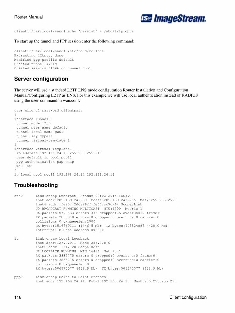
client1:/usr/local/sand# echo "persist" > /etc/l2tp.opts
To start up the tunnel and PPP session enter the following command:
client1:/usr/local/sand# /etc/rc.d/rc.localExtracting l2tp... doneModified ppp profile defaultCreated tunnel 47619Created session 61046 on tunnel tun1
Server configuration
The server will use a standard L2TP LNS mode configuration Router Installation and ConfigurationManual/Configuring L2TP as LNS. For this example we will use local authentication instead of RADIUSusing the user command in wan.conf.
user client1 password clientpass!interface Tunnel0 tunnel mode l2tp tunnel peer name default tunnel local name gw01 tunnel key mypass tunnel virtual-template 1!interface Virtual-Template1 ip address 192.168.24.13 255.255.255.248 peer default ip pool pool1 ppp authentication pap chap mtu 1500!ip local pool pool1 192.168.24.14 192.168.24.18
Troubleshooting
eth0 Link encap:Ethernet HWaddr 00:0C:29:57:CC:7C inet addr:205.159.243.30 Bcast:205.159.243.255 Mask:255.255.255.0 inet6 addr: fe80::20c:29ff:fe57:cc7c/64 Scope:Link UP BROADCAST RUNNING MULTICAST MTU:1500 Metric:1 RX packets:5790333 errors:378 dropped:25 overruns:0 frame:0 TX packets:2838910 errors:0 dropped:0 overruns:0 carrier:0 collisions:0 txqueuelen:1000 RX bytes:1516769111 (1446.5 Mb) TX bytes:448824887 (428.0 Mb) Interrupt:18 Base address:0x2000
lo Link encap:Local Loopback inet addr:127.0.0.1 Mask:255.0.0.0 inet6 addr: ::1/128 Scope:Host UP LOOPBACK RUNNING MTU:16436 Metric:1 RX packets:3835775 errors:0 dropped:0 overruns:0 frame:0 TX packets:3835775 errors:0 dropped:0 overruns:0 carrier:0 collisions:0 txqueuelen:0 RX bytes:506370077 (482.9 Mb) TX bytes:506370077 (482.9 Mb)
ppp0 Link encap:Point-to-Point Protocol inet addr:192.168.24.14 P-t-P:192.168.24.13 Mask:255.255.255.255
Router Manual
118 Client configuration
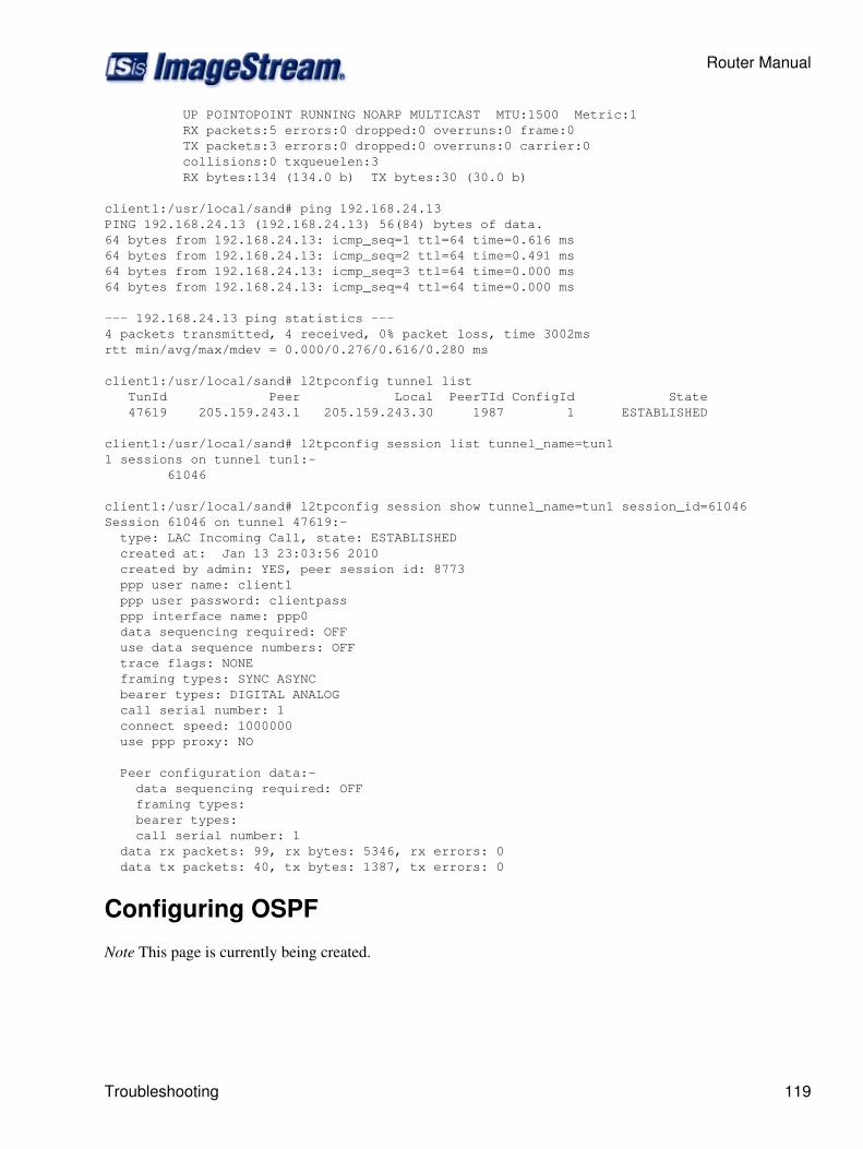
UP POINTOPOINT RUNNING NOARP MULTICAST MTU:1500 Metric:1 RX packets:5 errors:0 dropped:0 overruns:0 frame:0 TX packets:3 errors:0 dropped:0 overruns:0 carrier:0 collisions:0 txqueuelen:3 RX bytes:134 (134.0 b) TX bytes:30 (30.0 b)
client1:/usr/local/sand# ping 192.168.24.13PING 192.168.24.13 (192.168.24.13) 56(84) bytes of data.64 bytes from 192.168.24.13: icmp_seq=1 ttl=64 time=0.616 ms64 bytes from 192.168.24.13: icmp_seq=2 ttl=64 time=0.491 ms64 bytes from 192.168.24.13: icmp_seq=3 ttl=64 time=0.000 ms64 bytes from 192.168.24.13: icmp_seq=4 ttl=64 time=0.000 ms
--- 192.168.24.13 ping statistics ---4 packets transmitted, 4 received, 0% packet loss, time 3002msrtt min/avg/max/mdev = 0.000/0.276/0.616/0.280 ms
client1:/usr/local/sand# l2tpconfig tunnel list TunId Peer Local PeerTId ConfigId State 47619 205.159.243.1 205.159.243.30 1987 1 ESTABLISHED
client1:/usr/local/sand# l2tpconfig session list tunnel_name=tun11 sessions on tunnel tun1:- 61046
client1:/usr/local/sand# l2tpconfig session show tunnel_name=tun1 session_id=61046Session 61046 on tunnel 47619:- type: LAC Incoming Call, state: ESTABLISHED created at: Jan 13 23:03:56 2010 created by admin: YES, peer session id: 8773 ppp user name: client1 ppp user password: clientpass ppp interface name: ppp0 data sequencing required: OFF use data sequence numbers: OFF trace flags: NONE framing types: SYNC ASYNC bearer types: DIGITAL ANALOG call serial number: 1 connect speed: 1000000 use ppp proxy: NO
Peer configuration data:- data sequencing required: OFF framing types: bearer types: call serial number: 1 data rx packets: 99, rx bytes: 5346, rx errors: 0 data tx packets: 40, tx bytes: 1387, tx errors: 0
Configuring OSPF
Note This page is currently being created.
Router Manual
Troubleshooting 119
Overview
Open Shortest Path First, or OSPF, dynamically controls routing within a network. It's simplest useautomatically pushes route information to all branches of a network. Depending on network topology,it also provides redundancy, and the ability to control which connections are preferred to others.
Tools
Examples
Router Manual/Examples
Documentation and Futher reading
There quite a bit of documentation on Quagga/Zebra available.
/Troubleshooting - Tips to help track down common problems• /FAQ - ImageStream OSPF FAQ• /Glossary - Glossary of OSPF Terms• http://www.quagga.net/docs.php - Official Quagga documentation• http://forum.imagestream.com/phpbb/viewforum.php?f=2&sid=c0da447b7d71186e0d75066f31197948- ImageStream Dynamic Routing Support Forum
•
Configuring BGP
Overview
Border Gateway Protocol, or BGP, dynamically controls routing traffic between networks, or AutonomousSystems. Routers setup BGP peering sessions with each other and share information about what networksconnect to them directly, as well as what routes they learn from other peers. This means that if two BGP peerslose their session, the network knows this and can send traffic on an alternate path to its destination. Much ofthe internet uses BGP to ensure traffic flows quickly and efficiently to its destination rather than relying onhuman intervention to manage routes.
Examples
Router Manual/Examples
Documentation and Futher reading
Extensive documentation for Quagga is available from several different sources. The links below providetechnical information on the concepts, application, and troubleshooting of dynamic routing with Quagga.
ImageStream BGP FAQ•
Router Manual
120 Overview
BGP Troubleshooting• Glossary of BGP Terms• Official Quagga documentation•
Configuring Rate Limiting Within SAND
This chapter describes how to configure the ImageStream router to use Inetics' rate-limit commandsto limit inbound and outbound traffic on a WAN device. The rate-limit commands are used to limittraffic on an interface-by-interface basis. To limit traffic on a network-by-network orservice-by-service basis, see the chapter "Configuring Services: Quality of Service Menu."
This chapter includes the following topics:
Understanding and Configuring Rate Limiting◊ Valid Interfaces for the Rate-Limit Command◊
Before configuring rate limiting, you must configure the WAN interface and make the appropriatecabling connection for your needs. Refer to the hardware installation guide for your ImageStreamproduct for information on making the WAN connection. See the Command Reference for moredetailed command descriptions and instructions.
After logging in, the main menu is displayed (your menu may look slightly different):
Router main menu 1. Configuration menu 2. Show interface status 3. Advanced 4. Router software management 5. Backup/Restore 6. halt/reboot 0. Log off
Select menu option 1, Configuration menu, and press Enter to configure the router. TheConfiguration menu should appear (your menu may look slightly different):
Configuration menu 1. AAA (Password) Configuration 2. Global configuration 3. Network interface configuration 4. Firewall and QOS configuration 5. Service configuration 6. Dynamic routing configuration 7. Save configuration to flash 0. ISis-Router main menu
From the "Configuration menu", select menu option 3, Network interface configuration, and pressEnter. This will open the ImageStream router's primary configuration file, wan.conf in the defaulteditor. The wan.conf file is also accessible from the command line in the /usr/local/sand directory.
Router Manual
Documentation and Futher reading 121
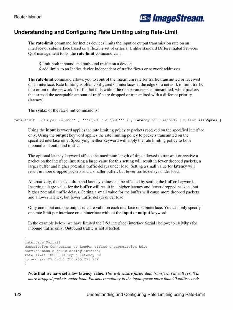
Understanding and Configuring Rate Limiting using Rate-Limit
The rate-limit command for Inetics devices limits the input or output transmission rate on aninterface or subinterface based on a flexible set of criteria. Unlike standard Differentiated ServicesQoS management tools, the rate-limit command can:
limit both inbound and outbound traffic on a device◊ add limits to an Inetics device independent of traffic flows or network addresses◊
The rate-limit command allows you to control the maximum rate for traffic transmitted or receivedon an interface. Rate limiting is often configured on interfaces at the edge of a network to limit trafficinto or out of the network. Traffic that falls within the rate parameters is transmitted, while packetsthat exceed the acceptable amount of traffic are dropped or transmitted with a different priority(latency).
The syntax of the rate-limit command is:
rate-limit bits per second"" [ """input | output""" ] [ latency milliseconds | buffer kilobytes ]
Using the input keyword applies the rate limiting policy to packets received on the specified interfaceonly. Using the output keyword applies the rate limiting policy to packets transmitted on thespecified interface only. Specifying neither keyword will apply the rate limiting policy to bothinbound and outbound traffic.
The optional latency keyword affects the maximum length of time allowed to transmit or receive apacket on the interface. Inserting a large value for this setting will result in fewer dropped packets, alarger buffer and higher potential traffic delays under load. Setting a small value for latency willresult in more dropped packets and a smaller buffer, but fewer traffic delays under load.
Alternatively, the packet drop and latency values can be affected by setting the buffer keyword.Inserting a large value for the buffer will result in a higher latency and fewer dropped packets, buthigher potential traffic delays. Setting a small value for the buffer will cause more dropped packetsand a lower latency, but fewer traffic delays under load.
Only one input and one output rule are valid on each interface or subinterface. You can only specifyone rate limit per interface or subinterface without the input or output keyword.
In the example below, we have limited the DS3 interface (interface Serial1 below) to 10 Mbps forinbound traffic only. Outbound traffic is not affected.
! interface Serial1 description Connection to London office encapsulation hdlc service-module ds3 clocking internal rate-limit 10000000 input latency 50 ip address 25.0.0.1 255.255.255.252 !
Note that we have set a low latency value. This will ensure faster data transfers, but will result inmore dropped packets under load. Packets remaining in the input queue more than 50 milliseconds
Router Manual
122 Understanding and Configuring Rate Limiting using Rate-Limit

will be dropped from the queue if they cannot be processed.
In the next example, we have limited the DS3 interface (interface Serial1 below) to 20 Mbps for bothinbound and outbound traffic. All traffic on this interface will share a common 20 Mbps rate limit.
! interface Serial1 description Connection to London office encapsulation hdlc service-module ds3 clocking internal rate-limit 20000000 input latency 1000 ip address 25.0.0.1 255.255.255.252 !
Note that we have set a very high latency value. This will increase the buffer size on the interfaceand ensure fewer packet drops. Packets will remain in the queue for up to 1000 milliseconds beforebeing dropped. Only extremely heavy traffic loads will cause significant packet drops using thisconfiguration.
Valid Interfaces for the Rate-Limit Command
The rate-limit command may be used on an interface or a subinterface. Inetics's rate limiting isindependent of the link encapsulation and the type of data and may be used with routed IP traffic orbridged traffic of any type. The rate-limit command is only valid for Inetics interfaces, and may notbe used on the following:
Ethernet interfaces◊ Token ring interfaces◊ Tunnel interfaces◊ VPN interfaces◊ VLAN interfaces◊
Note: You must save the settings to the router's non-volatile flash memory! If the router isrebooted before saving, your changes will be lost! See Chapter 26, "Backup/Restore Menu:Managing Configurations" for more information.
Configuring Services: Quality of Service Menu
This chapter describes how to configure settings for the Quality of Service (QoS) utilities provided bythe ImageStream router. This chapter describes how to configure the ImageStream router to useImageStream's bwinit and bwadd utilities. The bwinit and bwadd utilities are user-friendly interfacesto the more in-depth DiffServ utility, tc, provided on the router. Refer to the Linux Advanced Routingand Traffic Control HOWTO for additional information on using the tc commands and otheradvanced Linux routing utilities.
Quality of Service Menu
After logging in, the main menu is displayed (your menu may look slightly different):
ISis-Router main menu
Router Manual
Valid Interfaces for the Rate-Limit Command 123
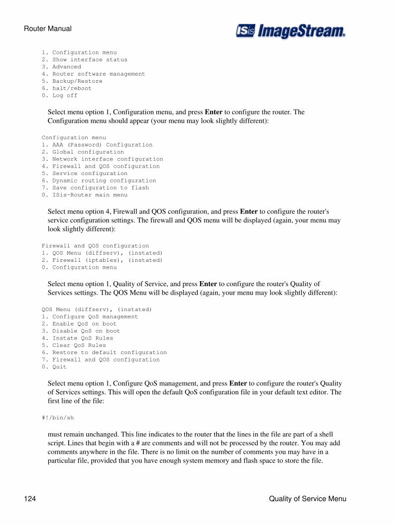
1. Configuration menu 2. Show interface status 3. Advanced 4. Router software management 5. Backup/Restore 6. halt/reboot 0. Log off
Select menu option 1, Configuration menu, and press Enter to configure the router. TheConfiguration menu should appear (your menu may look slightly different):
Configuration menu 1. AAA (Password) Configuration 2. Global configuration 3. Network interface configuration 4. Firewall and QOS configuration 5. Service configuration 6. Dynamic routing configuration 7. Save configuration to flash 0. ISis-Router main menu
Select menu option 4, Firewall and QOS configuration, and press Enter to configure the router'sservice configuration settings. The firewall and QOS menu will be displayed (again, your menu maylook slightly different):
Firewall and QOS configuration 1. QOS Menu (diffserv), (instated) 2. Firewall (iptables), (instated) 0. Configuration menu
Select menu option 1, Quality of Service, and press Enter to configure the router's Quality ofServices settings. The QOS Menu will be displayed (again, your menu may look slightly different):
QOS Menu (diffserv), (instated) 1. Configure QoS management 2. Enable QoS on boot 3. Disable QoS on boot 4. Instate QoS Rules 5. Clear QoS Rules 6. Restore to default configuration 7. Firewall and QOS configuration 0. Quit
Select menu option 1, Configure QoS management, and press Enter to configure the router's Qualityof Services settings. This will open the default QoS configuration file in your default text editor. Thefirst line of the file:
#!/bin/sh
must remain unchanged. This line indicates to the router that the lines in the file are part of a shellscript. Lines that begin with a # are comments and will not be processed by the router. You may addcomments anywhere in the file. There is no limit on the number of comments you may have in aparticular file, provided that you have enough system memory and flash space to store the file.
Router Manual
124 Quality of Service Menu

Configuring Quality of Service using Service, Policy and Interfacedefinitions
The latest 4.4.0 and 4.2.12 distributions utilize an improved policy-based configuration for quality ofservice. The default rc.qos script has examples that use a new QoS library of functions, greatlysimplifying QoS configuration.
Services define a type of traffic or service. Policies prioritize services, define how the traffic is queuedand set minimum and maximum rates as a percentage of the maximum rate. Interface definitionsapply a policy to an interface and define the maximum input and output rates as well as the maximumallowed latency for queued traffic. Because policy rates are specified using percentages a policy canbe applied to multiple interfaces which may have differing input and output rates.
QOS_SERVICE
The QOS_SERVICE command defines parameters that match a type of service such as Web traffic orSMTP traffic. ImageStream pre-defines many services that can be added to or modified.
Currently only tc filter matches are supported. See the Linux Advanced Routing and Traffic Controlguide for more information on tc filter matching.
Usage: QOS_SERVICE --name <service_name> [--init] --tc_match <tc_filter_command_match>Example:Create a new service called ims1 that matches traffic to and from 205.159.243.5
QOS_SERVICE --name ims1 --init --tc_match protocol ip u32 match ip src 205.159.243.5QOS_SERVICE --name ims1 --tc_match protocol ip u32 match ip dst 205.159.243.5
Release 4.4.0-77 adds a new --host option to simplify the match above:
QOS_SERVICE --name ims1 --init --host 205.159.243.5
It is also possible to add on to a pre-defined service. Simply omit the '--init' option to add anothermatch to a service.Example:In addition to the IP ToS bit matches also match on the SIP server's IP at 205.159.243.5.
QOS_SERVICE --name voip --tc-match protocol ip u32 match ip src 205.159.243.5QOS_SERVICE --name voip --tc-match protocol ip u32 match ip dst 205.159.243.5
QOS_POLICY
The QOS_POLICY command prioritizes and rate-limits services. Low latency queueing andclass-based queueing are supported.Low latency queueing provides a strict priority-based first-in-first-out (FIFO) queue which does notrate shape the traffic. This queueing method is preferred for real-time traffic such as VoIP and routingprotocols.
Router Manual
Configuring Quality of Service using Service, Policy and Interface definitions 125

Priorities range from 0 to 9. Lower values indicate higher priority.Minimum and maximum values are expressed as percentages ranging from 1 to 100. The actual ratewill be calculated using this percentage and the interface's real bandwidth.Class-based queueing provides prioritization but also performs rate shaping. This queueing method ispreferred for non-realtime traffic such as Web and E-mail.LLQ Usage: QOS_POLICY --name <policy_name> --type llq --service <service_name> --prio<priority 0-9> --max <max_percent>Example:
QOS_POLICY --name default --type llq --service voip --prio 0 --max 90
CBQ Usage: QOS_POLICY --name <policy_name> --type cbq [--default | --service<service_name>] --prio <priority 0-9> --min <min_percent> --max <max_percent>Example:Set the default traffic class to priority 5 and prioritize TCP ACKs higher than other traffic.
QOS_POLICY --name default --type cbq --default --prio 5 --min 10 --max 75QOS_POLICY --name default --type cbq --service ack --prio 3 --min 10 --max 40
QOS_IFACE
The QOS_IFACE command applies a policy to an interface. The maximum input and output rates arespecified in Kbps (Kilobits per second). Latency is specified in milliseconds.Fair queueing can also specified on the interface. ImageStream's PUFQ, standard fair-queueing andsimple first-in-first-out (FIFO) queueing are options.
FIFO Usage: QOS_IFACE --name <interface_name> --policy <policy_name> --max_in<input_rate_in_Kbps> --max-out <output_rate_in_Kbps> --max-latency <max_latency_in_ms>Example:Assign the default policy to Ethernet0 which has a 3.0 Mbps input and 640 Kbps output rate. We want150 ms max latency.
QOS_IFACE --name eth0 --policy default --max_in 3000 --max_out 640 --max_latency 150
Fair-Queueing Usage: QOS_IFACE --name <interface_name> --policy <policy_name> --max_in<input_rate_in_Kbps> --max-out <output_rate_in_Kbps> --max-latency <max_latency_in_ms>--fair_queuesfq advanced options
Example:Assign the default policy to Ethernet0 using fair queueing which has a 3.0 Mbps input and 640 Kbpsoutput rate. We want 150 ms max latency.
QOS_IFACE --name eth0 --policy default --max_in 3000 --max_out 640 --max_latency 150 --fair_queue
PUFQ Usage: QOS_IFACE --name <interface_name> --policy <policy_name> --max_in<input_rate_in_Kbps> --max-out <output_rate_in_Kbps> --max-latency <max_latency_in_ms>--pufq --pufq_iface_type <inside | outside | nat_inside | nat_outside>pufq advanced options
Router Manual
126 Configuring Quality of Service using Service, Policy and Interfacedefinitions

Example:Assign the default policy to Ethernet0 using PUFQ which has a 3.0 Mbps input and 640 Kbps outputrate. We want 150 ms max latency.
QOS_IFACE --name eth0 --policy default --max_in 3000 --max_out 640 --max_latency 150 --pufq --pufq_iface_type outside
ATM/DSL AdjustmentsStarting in 4.4.0-72 and 4.2.12-46 a new --calc_atm parameter was added to the QOS_IFACEstatement to allow the QOS subsystem to calculate ATM/AAL5 overhead for each packet beingtransmitted. This allows the system to specify the exact ATM data rate for the link.
Example:A 3.0 Mb / 512 K DSL link has synced up at 3520000 bps down and 768000 bps up.
QOS_IFACE --name eth0 --policy default --max_in 3520 --max_out 768 --max_latency 150 --fair_queue --calc_atm
Frame Relay Parametersframe relay options
Example:A 256K CIR burstable to 384K Frame Relay circuit
QOS_IFACE --name Serial0.1 --policy default --max_latency 150 --fair_queue --frame_relay_mincir 256000 --frame_relay_cir 384000
Advanced Example
################################################################################## Advanced example# Override the voip service definition. We define voip as traffic to/from# 192.168.0.35# Policy:# Low Latency Queues:# voip: Low Latency Queue with highest priority and maximum of 90% of the# interface's bandwidth.# Class-Based Queues:# telnet: Highest priority with min of 10% and max 40%.# ssh: Lower priority than telnet with min 10% and max 40%.# tcp acks: Lower priority than ssh with min of 10% and max of 40%.# smtp: Lowest priority with min of 10% and max 60%.# default: Priority 5 (just above smtp) with min 10% max 95%## Interface:# Apply the policy "default" to interface eth0 with the maximum input rate of# 3000 Kbps (3.0 Mbps) and maximum output rate of 640 Kbps with a maximum# queueing latency of 150 ms. Configure PUFQ with nat_outside as the interface type# since this interface performs SNAT on user traffic.#QOS_SERVICE --name voip --init --tc_match protocol ip u32 match ip src 192.168.0.35/32QOS_SERVICE --name voip --tc_match protocol ip u32 match ip dst 192.168.0.35/32QOS_POLICY --name default --type llq --service voip --prio 0 --max 90QOS_POLICY --name default --type cbq --init --default --prio 5 --min 10 --max 95QOS_POLICY --name default --type cbq --service telnet --prio 1 --min 10 --max 40QOS_POLICY --name default --type cbq --service ssh --prio 2 --min 10 --max 40
Router Manual
Configuring Quality of Service using Service, Policy and Interfacedefinitions 127
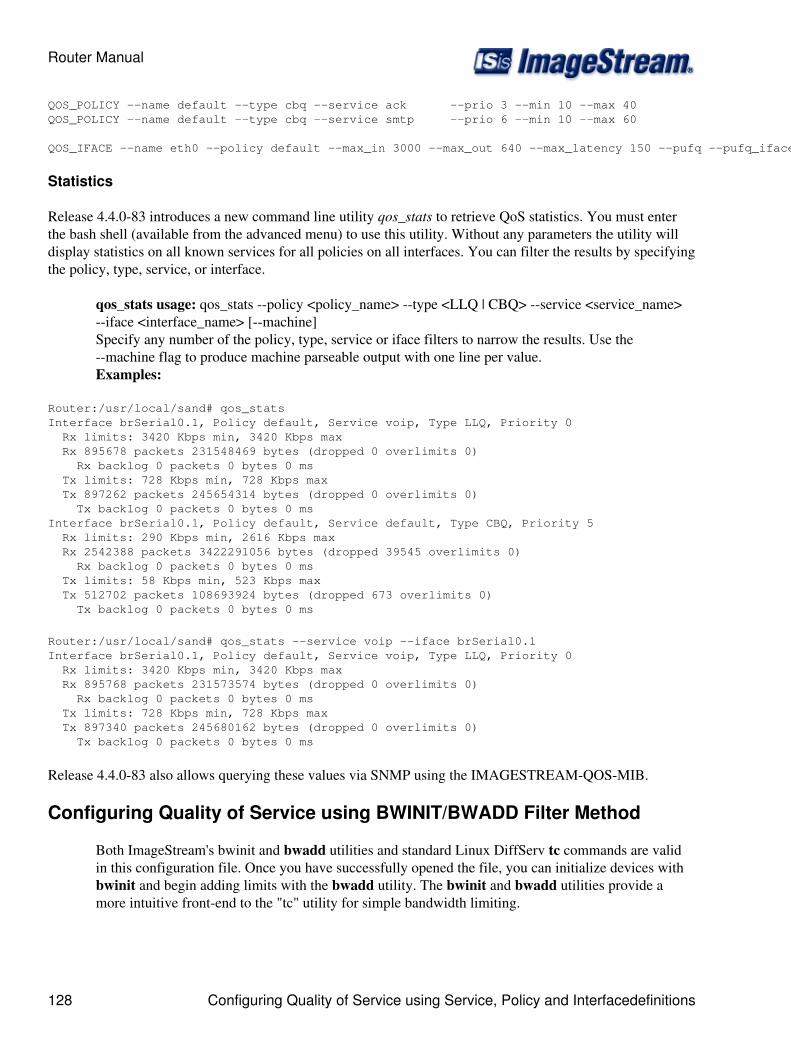
QOS_POLICY --name default --type cbq --service ack --prio 3 --min 10 --max 40QOS_POLICY --name default --type cbq --service smtp --prio 6 --min 10 --max 60
QOS_IFACE --name eth0 --policy default --max_in 3000 --max_out 640 --max_latency 150 --pufq --pufq_iface_type nat_outside
Statistics
Release 4.4.0-83 introduces a new command line utility qos_stats to retrieve QoS statistics. You must enterthe bash shell (available from the advanced menu) to use this utility. Without any parameters the utility willdisplay statistics on all known services for all policies on all interfaces. You can filter the results by specifyingthe policy, type, service, or interface.
qos_stats usage: qos_stats --policy <policy_name> --type <LLQ | CBQ> --service <service_name>--iface <interface_name> [--machine]Specify any number of the policy, type, service or iface filters to narrow the results. Use the--machine flag to produce machine parseable output with one line per value.Examples:
Router:/usr/local/sand# qos_statsInterface brSerial0.1, Policy default, Service voip, Type LLQ, Priority 0 Rx limits: 3420 Kbps min, 3420 Kbps max Rx 895678 packets 231548469 bytes (dropped 0 overlimits 0) Rx backlog 0 packets 0 bytes 0 ms Tx limits: 728 Kbps min, 728 Kbps max Tx 897262 packets 245654314 bytes (dropped 0 overlimits 0) Tx backlog 0 packets 0 bytes 0 msInterface brSerial0.1, Policy default, Service default, Type CBQ, Priority 5 Rx limits: 290 Kbps min, 2616 Kbps max Rx 2542388 packets 3422291056 bytes (dropped 39545 overlimits 0) Rx backlog 0 packets 0 bytes 0 ms Tx limits: 58 Kbps min, 523 Kbps max Tx 512702 packets 108693924 bytes (dropped 673 overlimits 0) Tx backlog 0 packets 0 bytes 0 ms
Router:/usr/local/sand# qos_stats --service voip --iface brSerial0.1Interface brSerial0.1, Policy default, Service voip, Type LLQ, Priority 0 Rx limits: 3420 Kbps min, 3420 Kbps max Rx 895768 packets 231573574 bytes (dropped 0 overlimits 0) Rx backlog 0 packets 0 bytes 0 ms Tx limits: 728 Kbps min, 728 Kbps max Tx 897340 packets 245680162 bytes (dropped 0 overlimits 0) Tx backlog 0 packets 0 bytes 0 ms
Release 4.4.0-83 also allows querying these values via SNMP using the IMAGESTREAM-QOS-MIB.
Configuring Quality of Service using BWINIT/BWADD Filter Method
Both ImageStream's bwinit and bwadd utilities and standard Linux DiffServ tc commands are validin this configuration file. Once you have successfully opened the file, you can initialize devices withbwinit and begin adding limits with the bwadd utility. The bwinit and bwadd utilities provide amore intuitive front-end to the "tc" utility for simple bandwidth limiting.
Router Manual
128 Configuring Quality of Service using Service, Policy and Interfacedefinitions
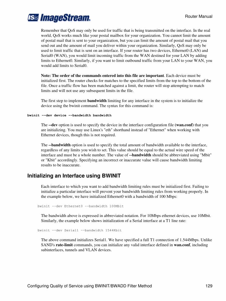
Remember that QoS may only be used for traffic that is being transmitted on the interface. In the realworld, QoS works much like your postal mailbox for your organization. You cannot limit the amountof postal mail that is sent to your organization, but you can limit the amount of postal mail that yousend out and the amount of mail you deliver within your organization. Similarly, QoS may only beused to limit traffic that is sent on an interface. If your router has two devices, Ethernet0 (LAN) andSerial0 (WAN), you would limit incoming traffic from the WAN destined for your LAN by addinglimits to Ethernet0. Similarly, if you want to limit outbound traffic from your LAN to your WAN, youwould add limits to Serial0.
Note: The order of the commands entered into this file are important. Each device must beinitialized first. The router checks for matches to the specified limits from the top to the bottom of thefile. Once a traffic flow has been matched against a limit, the router will stop attempting to matchlimits and will not use any subsequent limits in the file.
The first step to implement bandwidth limiting for any interface in the system is to initialize thedevice using the bwinit command. The syntax for this command is:
bwinit --dev device --bandwidth bandwidth
The --dev option is used to specify the device in the interface configuration file (wan.conf) that youare initializing. You may use Linux's "eth" shorthand instead of "Ethernet" when working withEthernet devices, though this is not required.
The --bandwidth option is used to specify the total amount of bandwidth available to the interface,regardless of any limits you wish to set. This value should be equal to the actual wire speed of theinterface and must be a whole number. The value of --bandwidth should be abbreviated using "Mbit"or "Kbit" accordingly. Specifying an incorrect or inaccurate value will cause bandwidth limitingresults to be inaccurate.
Initializing an Interface using BWINIT
Each interface to which you want to add bandwidth limiting rules must be initialized first. Failing toinitialize a particular interface will prevent your bandwidth limiting rules from working properly. Inthe example below, we have initialized Ethernet0 with a bandwidth of 100 Mbps:
bwinit --dev Ethernet0 --bandwidth 100Mbit
The bandwidth above is expressed in abbreviated notation. For 10Mbps ethernet devices, use 10Mbit.Similarly, the example below shows initialization of a Serial interface at a T1 line rate:
bwinit --dev Serial1 --bandwidth 1544Kbit
The above command initializes Serial1. We have specified a full T1 connection of 1.544Mbps. UnlikeSAND's rate-limit commands, you can initialize any valid interface defined in wan.conf, includingsubinterfaces, tunnels and VLAN devices.
Router Manual
Configuring Quality of Service using BWINIT/BWADD Filter Method 129
Adding Limits to Initialized Devices using BWADD
Once each interface you wish to manage has been initialized, you can add limiting rules. bwaddsupports separate limits on inbound and outbound bandwidth, as well as combinedinbound/outbound traffic limits. Various networks or IP addresses can be grouped together to sharea single bandwidth limit.
When adding limits, bwadd uses the following structure:
bwadd --dev device --bandwidth bandwidth { --source | --destination | --ip } ip address[/bitmask] \ [ --priority priority ] [ --group group number ] [ --fair-queue ]
The --dev option is used to specify the device in the interface configuration file (wan.conf) that youare initializing. You may use Linux's "eth" shorthand instead of "Ethernet" when working withEthernet devices, though this is not required.
The --bandwidth option is used to specify the total amount of bandwidth allocated to the interface.The value of --bandwidth should be abbreviated using "Mbit" or "Kbit" accordingly.
The [ --source | --destination | --ip ]' keywords are used to tell the router how to match thecorresponding IP or network block. --source will match only a packet's source address, --destinationwill match only a packet's destination address and --ip will match either address. Optionally, you mayspecify {/bitmask} which is used when the limit is for a network and not a single IP address/host. Atable is provided in Chapter 29, Router Installation and Configuration/Helpful Tools of this manual toconvert between netmasks and bitmasks.
The --priority keyword specifies the limit's routing priority. The default value is 8. The valid range is0 (highest) through 20 (lowest). The --priority keyword may be used to classify different networks,hosts or groups by level of importance. The network, host or group with the highest priority willalways have the first access to the available interface bandwidth to the exclusion of other networks,hosts or groups.
The --group option allows you to add a limit to a particular group. Using groups allows multiplenetworks or hosts to share an aggregate bandwidth. See Grouping hosts and networks below.
In the example below the Serial1 device has been set with the limit (512Kbit) for the 192.168.100.0class C network:
bwadd --dev Ethernet0 --bandwidth 512Kbit --ip 192.168.100.0/24 \ --group 3
When adding additional networks or hosts to an existing group, you do not need to respecify thebandwidth. Networks or hosts added to an existing group inherit the bandwidth limit previouslyspecified.
Note that when your command wraps beyond the end of the line, you must end the first linewith a backslash ( \ ). Failing to end a wrapped line with a backslash will cause the router tointerpret the next line as a new line and will generate an error.
Router Manual
130 Adding Limits to Initialized Devices using BWADD
The example command above would limit any host with a 192.168.100.xx address to 512Kbps ofbandwidth inbound and outbound. By specifying the keyword --ip, hosts share a single 512Kbpsbandwidth limit, regardless of whether the 192.168.10.xx address is in the source or destination fieldsof the IP packet. Additionally, a group number (3) has been specified. Other hosts or networks cannow be added to the group and share the allocated bandwidth.
To limit destination traffic only to an aggregate bandwidth of 512Kbps, use the --destinationkeyword:
bwadd --dev Ethernet0 --bandwidth 512Kbit --destination \ 192.168.100.0/24 --group 3
Similarly, to limit source traffic only to an aggregate bandwidth of 512Kbps, use the --sourcekeyword:
bwadd --dev eth0 --bandwidth 512Kbit -source 192.168.100.0/24 \ --group 3
Again, note the use of the backslash to wrap at the end of the first line in both commands. Theuse of the backslash is only necessary when the commands wraps across more than one line in yourdisplay. We have also used the shorthand "eth0" notation in the second example. Either "Ethernet0" or"eth0" is acceptable.
Grouping Hosts and Networks
Using the group keyword allows other hosts and networks to share a common bandwidth limit. Wehave configured the below example based on the Serial0 device initialized in our example above:
bwadd --dev Serial0 --bandwidth 1Mbit --ip 172.0.0.0/24 \ --group 2 bwadd --dev Serial0 --ip 172.1.1.0/24 --group 2 bwadd --dev Serial0 --bandwidth 512Kbit --ip 172.20.1.0/24
This example will limit 172.0.0.0/24 and 172.1.1.0/24 to 10Mbit and 172.0.1.0/24 to 1Mbit on the T1link. Note that to add 172.1.1.0/24 to group 2, you only need to specify the device, address range andgroup number. 172.20.1.0/24 inherits the bandwidth limit specified in the previous command.
Configuring Quality of Service using BWINIT/BWADD Classify Method
In this example, we are going to assume the following service classes:
Voice over IP phone with highest priority at 192.168.1.5◊ SSH/telnet (interactive character) traffic with high priority◊ "Default" service class for all non-classified traffic◊ Non-realtime e-mail traffic at low priority◊ Security camera (192.168.1.6) FTP traffic at low priority◊
The configuration will define five service classes under a common leaf class:
Router Manual
Grouping Hosts and Networks 131
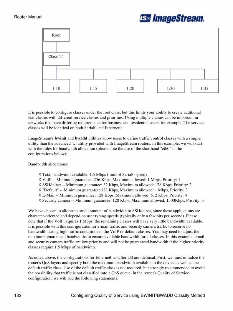
It is possible to configure classes under the root class, but this limits your ability to create additionalleaf classes with different service classes and priorities. Using multiple classes can be important innetworks that have differing requirements for business and residential users, for example. The serviceclasses will be identical on both Serial0 and Ethernet0.
ImageStream's bwinit and bwadd utilities allow users to define traffic control classes with a simplerutility than the advanced 'tc' utility provided with ImageStream routers. In this example, we will startwith the rules for bandwidth allocation (please note the use of the shorthand "eth0" in theconfigurations below):
Bandwidth allocations:
Total bandwidth available: 1.5 Mbps (limit of Serial0 speed)◊ VoIP -- Minimum guarantee: 256 Kbps, Maximum allowed: 1 Mbps, Priority: 1◊ SSH/telnet -- Minimum guarantee: 32 Kbps, Maximum allowed: 128 Kbps, Priority: 2◊ "Default" -- Minimum guarantee: 128 Kbps, Maximum allowed: 1 Mbps, Priority: 3◊ E-Mail -- Minimum guarantee: 128 Kbps, Maximum allowed: 512 Kbps, Priority: 4◊ Security camera -- Minimum guarantee: 128 Kbps, Maximum allowed: 1500Kbps, Priority: 5◊
We have chosen to allocate a small amount of bandwidth to SSH/telnet, since these applications arecharacter-oriented and depend on user typing speeds (typically only a few bits per second). Pleasenote that if the VoIP requires 1 Mbps, the remaining classes will have very little bandwidth available.It is possible with this configuration for e-mail traffic and security camera traffic to receive nobandwidth during high traffic conditions in the VoIP or default classes. You may need to adjust themaximum guaranteed bandwidths to ensure available bandwidth for all classes. In this example, emailand security camera traffic are low priority and will not be guaranteed bandwidth if the higher priorityclasses require 1.5 Mbps of bandwidth.
As noted above, the configurations for Ethernet0 and Serial0 are identical. First, we must initialize therouter's QoS layers and specify both the maximum bandwidth available to the device as well as thedefault traffic class. Use of the default traffic class is not required, but strongly recommended to avoidthe possibility that traffic is not classified into a QoS queue. In the router's Quality of Serviceconfiguration, we will add the following statements:
Router Manual
132 Configuring Quality of Service using BWINIT/BWADD Classify Method

bwinit --dev eth0 --bandwidth 1536Kbit --default 20 bwinit --dev Serial0 --bandwidth 1536Kbit --default 20
In the above configuration, we have specified a device (eth0 and Serial0, respectively), the totalbandwidth available (1.5 Mbps, or T1 speeds) to both devices and a default traffic class (20, in bothcases). The default class instructs the router to sort all unclassified traffic into class 20 automatically.
Next, we must configure the bandwidth allocations for each of the five classes specified above:
Rules for Ethernet01.
bwadd --dev eth0 --classid 10 --minimum 256Kbit \ --maximum 1Mbit --priority 1 bwadd --dev eth0 --classid 15 --minimum 32Kbit \ --maximum 128Kbit --priority 2 bwadd --dev eth0 --classid 20 --minimum 128Kbit \ --maximum 1Mbit --priority 3 --fair-queue bwadd --dev eth0 --classid 30 --minimum 128Kbit \ --maximum 512Kbit --priority 4 --fair-queue bwadd --dev eth0 --classid 35 --minimum 128Kbit \ --maximum 1500Kbit --priority 5 --fair-queue
Rules for Serial01.
bwadd --dev Serial0 --classid 10 --minimum 256Kbit \ --maximum 1Mbit --priority 1 bwadd --dev Serial 0 --classid 15 --minimum 32Kbit \ --maximum 128Kbit --priority 2 bwadd --dev Serial 0 --classid 20 --minimum 128Kbit \ --maximum 1Mbit --priority 3 --fair-queue bwadd --dev Serial 0 --classid 30 --minimum 128Kbit \ --maximum 512Kbit --priority 4 --fair-queue bwadd --dev Serial 0 --classid 35 --minimum 128Kbit \ --maximum 1500Kbit --priority 5 --fair-queue
Again, please note that the rules for Ethernet0 and Serial0 are identical. Each set of queues will applyonly in the transmit direction ("upstream" traffic leaves on Serial0, "downstream" traffic leaves therouter on Ethernet0). In most networks where upload and download speeds are symmetric, the rulesfor the inward-facing and outward-facing interfaces will be identical. The class identification numberswe have chosen for this example are arbitrary. You may select a range of valid integers, and the classidentifiers do not have to match from interface to interface.
The rules follow a common format:
bwadd - Specifies that the router is adding a rule to an initialized interface.
--dev DEVICE - Specifies that the router is adding a rule to the device named DEVICE.
--classid XX - Configures a QoS class with the identifier "XX". This class value is used later byiptables.
--minimum XX - Configures the minimum guaranteed bandwidth ("XX") for this class. The routerwill attempt to always guarantee this amount of traffic to the class.
Kbit, Mbit - Notation used to specify Kilobits and Megabits. Only whole numbers are valid, so 1.5Megabit becomes 1500Kbit.
--maximum XX - Configures the maximum allowed bandwidth ("XX") for this class. The router willnot allow traffic in this class to exceed the specified maximum.
Router Manual
Configuring Quality of Service using BWINIT/BWADD Classify Method 133
--priority XX - Specifies an optional priority value ("XX") from 0 to 8 used to rank classes in orderof bandwidth allocations.
The --fair-queue option enables Stochastic Fair Queuing (SFQ) for the class. This option accepts noconfiguration variables. The router will allocate bandwidth fairly to all class members. This isespecially useful in busy classes where a combination of users with different bandwidth usage profilesshare a common bandwidth limit. SFQ's help to avoid a single user or small group of users from usingall of the bandwidth available to a class to the exclusion of other class members.
Both the --minimum and --maximum values are not required. You may specify only a minimum ormaximum, and the router will automatically set the two values equal to each other. The router will notattempt to check for oversubscriptions or overallocations. Please carefully check your configurationsfor proper bandwidth allocation for your network requirements. Save your Quality of Serviceconfiguration. It is not necessary to instate the rules immediately, but you will need to instate the rulesbefore the configuration will take effect.
Classifying Traffic using iptables CLASSIFY
Now we need to sort the traffic into their proper queues. While it is possible to do this from within the"tc" QoS utility, using the iptables CLASSIFY directive provides a simpler, more flexible and morepowerful method. In the router's firewall configuration (Option 1, Option 4, Option 2, Option 1 fromthe main menu), we will add the following statements below. For our VoIP phone, we can matchtraffic based on the source or destination IP address. We will map traffic coming from (Serial0) orgoing to (Ethernet0) the address 192.168.69.5 and add that traffic to class 1:10, which we mapped outoriginally and configured in the previous step:
#Phone traffic iptables -A POSTROUTING -t mangle -o eth0 -d 192.168.69.5 \ -j CLASSIFY --set-class 1:10 iptables -A POSTROUTING -t mangle -o Serial0 -s 192.168.69.5 \ -j CLASSIFY --set-class 1:10
The iptables CLASSIFY directives are always added to the POSTROUTING chain's mangle table.Note the difference between the two rules, which is the use of -s and -d with the "192.168.69.5"address. For traffic leaving the network on Serial0, 192.168.69.5 will be the source address. For replytraffic returning to the network (Ethernet0), the 192.168.69.5 will appear as the destination address.For more information on the path a packet follows through iptables, please see the iptables HOWTO.
The rules use several different elements, explained below:
iptables - Specifies that the router is adding an iptables rule
-A POSTROUTING - Appends (-A) a rule to the router's POSTROUTING chain
-t mangle - Appends the rule to the mangle (-t mangle) table inside the specified chain
-o eth0, -o Serial0 - Specifies that only packets that match the specified outbound (-o) interface willmatch the rule. CLASSIFY rules will always be applied to an outbound interface.
-d XX - Specifies that only packets with a destination address of "XX" will match the rule.
Router Manual
134 Classifying Traffic using iptables CLASSIFY
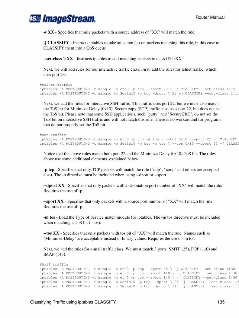
-s XX - Specifies that only packets with a source address of "XX" will match the rule.
-j CLASSIFY - Instructs iptables to take an action (-j) on packets matching this rule, in this case toCLASSIFY them into a QoS queue
--set-class 1:XX - Instructs iptables to add matching packets to class ID 1:XX.
Next, we will add rules for our interactive traffic class. First, add the rules for telnet traffic, whichuses port 23:
#telnet traffic iptables -A POSTROUTING -t mangle -o eth0 -p tcp --sport 23 \ -j CLASSIFY --set-class 1:15 iptables -A POSTROUTING -t mangle -o Serial0 -p tcp -dport \ 23 -j CLASSIFY --set-class 1:15
Next, we add the rules for interactive SSH traffic. This traffic uses port 22, but we must also matchthe ToS bit for Minimize-Delay (0x10). Secure copy (SCP) traffic also uses port 22, but does not setthe ToS bit. Please note that some SSH applications, such "putty" and "SecureCRT", do not set theToS bit on interactive SSH traffic and will not match this rule. There is no workaround for programsthat do not properly set the ToS bit.
#ssh traffic iptables -A POSTROUTING -t mangle -o eth0 -p tcp -m tos \ --tos 0x10 --sport 22 -j CLASSIFY --set-class 1:15 iptables -A POSTROUTING -t mangle -o Serial0 -p tcp -m tos \ --tos 0x10 --dport 22 -j CLASSIFY --set-class 1:15
Notice that the above rules match both port 22 and the Minimize-Delay (0x10) ToS bit. The rulesabove use some additional elements, explained below:
-p tcp - Specifies that only TCP packets will match the rule ("udp", "icmp" and others are acceptedalso). The -p directive must be included when using --dport or --sport.
--dport XX - Specifies that only packets with a destination port number of "XX" will match the rule.Requires the use of -p.
--sport XX - Specifies that only packets with a source port number of "XX" will match the rule.Requires the use of -p.
-m tos - Load the Type of Service match module for iptables. The -m tos directive must be includedwhen matching a ToS bit (--tos).
--tos XX - Specifies that only packets with tos bit of "XX" will match the rule. Names such as"Minimize-Delay" are acceptable instead of binary values. Requires the use of -m tos.
Next, we add the rules for e-mail traffic class. We must match 3 ports: SMTP (25), POP (110) andIMAP (143):
#Mail traffic iptables -A POSTROUTING -t mangle -o eth0 -p tcp --sport 25 \ -j CLASSIFY --set-class 1:30 iptables -A POSTROUTING -t mangle -o eth0 -p tcp --sport 110 \ -j CLASSIFY --set-class 1:30 iptables -A POSTROUTING -t mangle -o eth0 -p tcp --sport 143 \ -j CLASSIFY --set-class 1:30 iptables -A POSTROUTING -t mangle -o Serial0 -p tcp --dport \ 25 -j CLASSIFY --set-class 1:30 iptables -A POSTROUTING -t mangle -o Serial0 -p tcp -dport \ 110 -j CLASSIFY --set-class 1:30
Router Manual
Classifying Traffic using iptables CLASSIFY 135
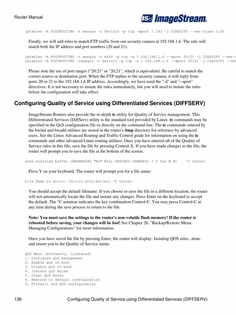
iptables -A POSTROUTING -t mangle -o Serial0 -p tcp -dport \ 143 -j CLASSIFY --set-class 1:30
Finally, we will add rules to match FTP traffic from our security camera at 192.168.1.6. The rule willmatch both the IP address and port numbers (20 and 21):
iptables -A POSTROUTING -t mangle -o eth0 -p tcp -d \ 192.168.1.6 --sport 20:21 -j CLASSIFY --set-class 1:35 iptables -A POSTROUTING -tmangle -o Serial0 -p tcp -s \ 192.168.1.6 --dport 20:21 -j CLASSIFY --set-class 1:35
Please note the use of port ranges ("20:21" or "20,21", which is equivalent). Be careful to match thecorrect source or destination port. When the FTP replies to the security camera, it will reply fromports 20 or 21 to the 192.168.1.6 IP address. Accordingly, we have used the "-d" and "--sport"directives. It is not necessary to instate the rules immediately, but you will need to instate the rulesbefore the configuration will take effect.
Configuring Quality of Service using Differentiated Services (DIFFSERV)
ImageStream Routers also provide the in-depth tc utility for Quality of Service management. ThisDifferentiated Services (DiffServ) utility is the standard tool provided by Linux. tc commands may bespecified in the QoS configuration file or directly on the command line. The tc commands entered bythe bwinit and bwadd utilities are stored in the router's /tmp directory for reference by advancedusers. See the Linux Advanced Routing and Traffic Control guide for information on using the tccommands and other advanced Linux routing utilities. Once you have entered all of the Quality ofService rules in this file, save the file by pressing Control-X. If you have made changes to the file, therouter will prompt you to save the file at the bottom of the screen:
Save modified buffer (ANSWERING "No" WILL DESTROY CHANGES) ? Y Yes N No ^C Cancel
Press Y on your keyboard. The router will prompt you for a file name:
File Name to write: /etc/rc.d/rc.bwlimit ^C Cancel
You should accept the default filename. If you choose to save the file in a different location, the routerwill not automatically locate the file and instate any changes. Press Enter on the keyboard to acceptthe default. The ^C notation indicates the key combination Control-C. You may press Control-C atany time during the save process to return to the file.
Note: You must save the settings to the router's non-volatile flash memory! If the router isrebooted before saving, your changes will be lost! See Chapter 26, "Backup/Restore Menu:Managing Configurations" for more information.
Once you have saved the file by pressing Enter, the router will display: Instating QOS rules...done.and return you to the Quality of Service menu:
QOS Menu (diffserv), (instated) 1. Configure QoS management 2. Enable QoS on boot 3. Disable QoS on boot 4. Instate QoS Rules 5. Clear QoS Rules 6. Restore to default configuration 0. Firewall and QOS configuration
Router Manual
136 Configuring Quality of Service using Differentiated Services (DIFFSERV)
Enabling QoS at Boot-time
2. Enable QoS on boot
Selecting this menu option enables the QoS rules when the router is booted. This does not start QoSon the router if it is not running, unless the router is rebooted first. By default, the QoS configurationis enabled on boot. To enable QoS on boot, select this menu option by pressing 2 and Enter. Therouter will display the message:
QOS enabled on boot
If the QoS configuration has already been enabled on boot, the router will display the message:
QOS already enabled on boot
The resulting message will only be displayed for a few seconds, and then you will be returned to theQuality of Service menu.
Disabling QoS at Boot-time
3. Disable QoS on boot
Selecting this menu option disables the QoS rules when the router is booted. This does not stop QoSon the router if it is running, unless the router is rebooted first. To disable QoS on boot, select thismenu option by pressing 3 and Enter. The router will display the following message:
QOS disabled on boot.
If the QoS configuration has already been disabled on boot, the router will display the message:
QOS already disabled on boot.
The resulting message will only be displayed for a few seconds, and then you will be returned to theQuality of Service menu.
Instating QoS Rules
4. Instate QoS rules
Selecting this menu option instates the QoS configuration on the router. Instating the QoSconfiguration does not automatically enable QoS when the router is booted. To instate the QoS rules,select this menu option by pressing 4 and Enter. The router will display the following message:
Instating QoS rules...done.
The message will only be displayed for a few seconds, and then you will be returned to the Quality ofService menu.
Router Manual
Enabling QoS at Boot-time 137
Clearing QoS Rules
5. Clear QoS rules
Selecting menu option clears the QoS configuration on the router. Clearing the QoS configurationdoes not automatically disable QoS when the router is booted. To clear the QoS rules, select thismenu option by pressing 5 and Enter. The router will display the following message:
Clearing QOS rules...done.
The message will only be displayed for a few seconds, and then you will be returned to the Quality ofService menu.
Restoring Factory Default QoS Configuration
6. Restore to default configuration
Selecting this menu option removes the stored QoS configuration from the router's nonvolatile flashmemory. Selecting this menu option and confirming your selection will remove any user-defined QoSconfigurations from the router. This will not instate or clear any of the rules, and will not enable ordisable QoS rules. Selecting this option will restore the router to the factory default QoS configurationonly.
To restore the factory default QoS rules, select this menu option by pressing 6 and Enter. The router willdisplay a confirmation menu:
Set default config for qos? 1. Yes 2. No 0. Quit
Pressing 2 or 0 and Enter will return you to the Quality of Service menu without making any changesto the configuration. Confirming your decision to restore the factory default QoS configuration bypressing 1 and Enter will display:
qos returned to default configuration. Press enter/return to continue
Press Enter to return to the Quality of Service menu.
Returning to the Firewall/QOS Configuration Menu
0. Firewall and QOS configuration
Selecting this menu option returns you to the "Firewall and QoS configuration" menu. To return to theService configuration menu, press 0 on and Enter. The router will display the Service configurationmenu:
Firewall and QOS configuration 1. QOS Menu (diffserv), (instated)
Router Manual
138 Clearing QoS Rules

2. Firewall (iptables), (instated) 0. Configuration menu
Configuring Services: Dialout PPP Menu
This chapter describes how to configure settings for the Dialout PPP utilities provided by theImageStream router. This chapter describes how to configure the ImageStream router to use a modemfor dial-out WAN connectivity.
This chapter discusses the following topics:
Configuring Dialout PPP◊ Enabling Dialout PPP at boot-time◊ Disabling Dialout PPP at boot-time◊ Instating Dialout PPP rules in the running configuration◊ Clearing Dialout PPP rules from the running configuration◊ Viewing dialer messages◊
After logging in, the main menu is displayed (your menu may look slightly different):
ISis-Router main menu 1. Configuration menu 2. Show interface status 3. Advanced 4. Router software management 5. Backup/Restore 6. halt/reboot 0. Log off
Select menu option 1, Configuration menu, and press Enter to configure the router. TheConfiguration menu should appear (your menu may look slightly different):
Configuration menu 1. AAA (Password) Configuration 2. Global configuration 3. Network interface configuration 4. Firewall and QOS configuration 5. Service configuration 6. Dynamic routing configuration 7. Save configuration to flash 0. ISis-Router main menu
Select menu option 5, Service configuration menu, and press Enter to configure the router's serviceconfiguration settings. The Service configuration menu will be displayed (again, your menu may lookslightly different):
Service configuration 1. System scheduler (cron), (running) 2. Dialout PPP, (stopped) 3. IPSec VPN (Free S/Wan), (stopped) 4. NetFlow exporter (nprobe), (stopped) 5. network interfaces (sand), (running) 6. sconsole (mgetty), (running)
Router Manual
Returning to the Firewall/QOS Configuration Menu 139
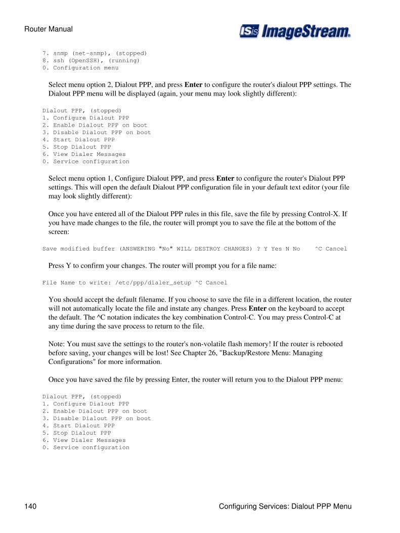
7. snmp (net-snmp), (stopped) 8. ssh (OpenSSH), (running) 0. Configuration menu
Select menu option 2, Dialout PPP, and press Enter to configure the router's dialout PPP settings. TheDialout PPP menu will be displayed (again, your menu may look slightly different):
Dialout PPP, (stopped) 1. Configure Dialout PPP 2. Enable Dialout PPP on boot 3. Disable Dialout PPP on boot 4. Start Dialout PPP 5. Stop Dialout PPP 6. View Dialer Messages 0. Service configuration
Select menu option 1, Configure Dialout PPP, and press Enter to configure the router's Dialout PPPsettings. This will open the default Dialout PPP configuration file in your default text editor (your filemay look slightly different):
Once you have entered all of the Dialout PPP rules in this file, save the file by pressing Control-X. Ifyou have made changes to the file, the router will prompt you to save the file at the bottom of thescreen:
Save modified buffer (ANSWERING "No" WILL DESTROY CHANGES) ? Y Yes N No ^C Cancel
Press Y to confirm your changes. The router will prompt you for a file name:
File Name to write: /etc/ppp/dialer_setup ^C Cancel
You should accept the default filename. If you choose to save the file in a different location, the routerwill not automatically locate the file and instate any changes. Press Enter on the keyboard to acceptthe default. The ^C notation indicates the key combination Control-C. You may press Control-C atany time during the save process to return to the file.
Note: You must save the settings to the router's non-volatile flash memory! If the router is rebootedbefore saving, your changes will be lost! See Chapter 26, "Backup/Restore Menu: ManagingConfigurations" for more information.
Once you have saved the file by pressing Enter, the router will return you to the Dialout PPP menu:
Dialout PPP, (stopped) 1. Configure Dialout PPP 2. Enable Dialout PPP on boot 3. Disable Dialout PPP on boot 4. Start Dialout PPP 5. Stop Dialout PPP 6. View Dialer Messages 0. Service configuration
Router Manual
140 Configuring Services: Dialout PPP Menu
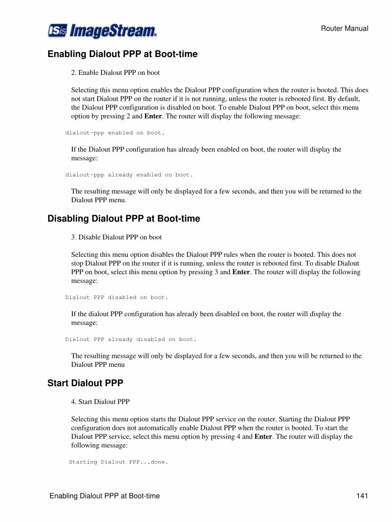
Enabling Dialout PPP at Boot-time
2. Enable Dialout PPP on boot
Selecting this menu option enables the Dialout PPP configuration when the router is booted. This doesnot start Dialout PPP on the router if it is not running, unless the router is rebooted first. By default,the Dialout PPP configuration is disabled on boot. To enable Dialout PPP on boot, select this menuoption by pressing 2 and Enter. The router will display the following message:
dialout-ppp enabled on boot.
If the Dialout PPP configuration has already been enabled on boot, the router will display themessage:
dialout-ppp already enabled on boot.
The resulting message will only be displayed for a few seconds, and then you will be returned to theDialout PPP menu.
Disabling Dialout PPP at Boot-time
3. Disable Dialout PPP on boot
Selecting this menu option disables the Dialout PPP rules when the router is booted. This does notstop Dialout PPP on the router if it is running, unless the router is rebooted first. To disable DialoutPPP on boot, select this menu option by pressing 3 and Enter. The router will display the followingmessage:
Dialout PPP disabled on boot.
If the dialout PPP configuration has already been disabled on boot, the router will display themessage:
Dialout PPP already disabled on boot.
The resulting message will only be displayed for a few seconds, and then you will be returned to theDialout PPP menu
Start Dialout PPP
4. Start Dialout PPP
Selecting this menu option starts the Dialout PPP service on the router. Starting the Dialout PPPconfiguration does not automatically enable Dialout PPP when the router is booted. To start theDialout PPP service, select this menu option by pressing 4 and Enter. The router will display thefollowing message:
Starting Dialout PPP...done.
Router Manual
Enabling Dialout PPP at Boot-time 141

The message will only be displayed for a few seconds, and then you will be returned to the DialoutPPP menu.
Stop Dialout PPP
5. Stop Dialout PPP
Selecting this menu option stop the Dialout PPP service on the router. Stopping the Dialout PPPconfiguration does not automatically disable Dialout PPP when the router is booted. To stop theDialout PPP service, select this menu option by pressing 4 and Enter. The router will display thefollowing message:
Stopping Dialout PPP...done.
The message will only be displayed for a few seconds, and then you will be returned to the DialoutPPP menu.
Viewing Dialer Messages
6. View dialer messages
Selecting this menu option will display any PPP dialer messages stored in the dialer log. If there areno messages in the log, the screen will display:
No messages.
Otherwise, the contents of the dialer log will be display using the less program. less allows you toscroll through the contents of the file using the arrow keys. At the bottom of the output, you will seethe following message:
Hit Q to exit.
Press 'Q' or 'q' on the keyboard to exit the log output and return to the Dialout PPP menu
Returning to the Service Configuration Menu
0. Service configuration
Selecting this menu option returns you to the "Service configuration" menu. To return to the Serviceconfiguration menu, press 0 and Enter. The router will display the Service configuration menu:
Service configuration 1. System scheduler (cron), (running) 2. Dialout PPP, (stopped) 3. IPSec VPN (Free S/Wan), (stopped) 4. NetFlow exporter (nprobe), (stopped) 5. network interfaces (sand), (running) 6. sconsole (mgetty), (running) 7. snmp (net-snmp), (stopped) 8. ssh (OpenSSH), (running)
Router Manual
142 Start Dialout PPP
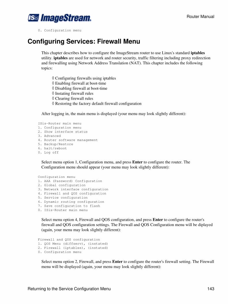
0. Configuration menu
Configuring Services: Firewall Menu
This chapter describes how to configure the ImageStream router to use Linux's standard iptablesutility. iptables are used for network and router security, traffic filtering including proxy redirectionand firewalling using Network Address Translation (NAT). This chapter includes the followingtopics:
Configuring firewalls using iptables◊ Enabling firewall at boot-time◊ Disabling firewall at boot-time◊ Instating firewall rules◊ Clearing firewall rules◊ Restoring the factory default firewall configuration◊
After logging in, the main menu is displayed (your menu may look slightly different):
ISis-Router main menu 1. Configuration menu 2. Show interface status 3. Advanced 4. Router software management 5. Backup/Restore 6. halt/reboot 0. Log off
Select menu option 1, Configuration menu, and press Enter to configure the router. TheConfiguration menu should appear (your menu may look slightly different):
Configuration menu 1. AAA (Password) Configuration 2. Global configuration 3. Network interface configuration 4. Firewall and QOS configuration 5. Service configuration 6. Dynamic routing configuration 7. Save configuration to flash 0. ISis-Router main menu
Select menu option 4, Firewall and QOS configuration, and press Enter to configure the router'sfirewall and QOS configuration settings. The Firewall and QOS Configuration menu will be diplayed(again, your menu may look slightly different):
Firewall and QOS configuration 1. QOS Menu (diffserv), (instated) 2. Firewall (iptables), (instated) 0. Configuration menu
Select menu option 2, Firewall, and press Enter to configure the router's firewall setting. The Firewallmenu will be displayed (again, your menu may look slightly different):
Router Manual
Returning to the Service Configuration Menu 143
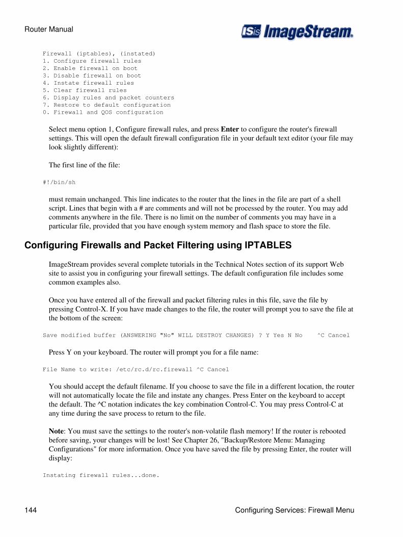
Firewall (iptables), (instated) 1. Configure firewall rules 2. Enable firewall on boot 3. Disable firewall on boot 4. Instate firewall rules 5. Clear firewall rules 6. Display rules and packet counters 7. Restore to default configuration 0. Firewall and QOS configuration
Select menu option 1, Configure firewall rules, and press Enter to configure the router's firewallsettings. This will open the default firewall configuration file in your default text editor (your file maylook slightly different):
The first line of the file:
#!/bin/sh
must remain unchanged. This line indicates to the router that the lines in the file are part of a shellscript. Lines that begin with a # are comments and will not be processed by the router. You may addcomments anywhere in the file. There is no limit on the number of comments you may have in aparticular file, provided that you have enough system memory and flash space to store the file.
Configuring Firewalls and Packet Filtering using IPTABLES
ImageStream provides several complete tutorials in the Technical Notes section of its support Website to assist you in configuring your firewall settings. The default configuration file includes somecommon examples also.
Once you have entered all of the firewall and packet filtering rules in this file, save the file bypressing Control-X. If you have made changes to the file, the router will prompt you to save the file atthe bottom of the screen:
Save modified buffer (ANSWERING "No" WILL DESTROY CHANGES) ? Y Yes N No ^C Cancel
Press Y on your keyboard. The router will prompt you for a file name:
File Name to write: /etc/rc.d/rc.firewall ^C Cancel
You should accept the default filename. If you choose to save the file in a different location, the routerwill not automatically locate the file and instate any changes. Press Enter on the keyboard to acceptthe default. The ^C notation indicates the key combination Control-C. You may press Control-C atany time during the save process to return to the file.
Note: You must save the settings to the router's non-volatile flash memory! If the router is rebootedbefore saving, your changes will be lost! See Chapter 26, "Backup/Restore Menu: ManagingConfigurations" for more information. Once you have saved the file by pressing Enter, the router willdisplay:
Instating firewall rules...done.
Router Manual
144 Configuring Services: Firewall Menu
and return you to the firewall menu:
Firewall (iptables), (instated) 1. Configure firewall rules 2. Enable firewall on boot 3. Disable firewall on boot 4. Instate firewall rules 5. Clear firewall rules 6. Display rules and packet counters 7. Restore to default configuration 0. Firewall and QOS configuration
Enabling firewall Rules at Boot-time
2. Enable firewall on boot
Selecting this menu option enables the firewall rules when the router is booted. This does not instatethe firewall rules on the router if it is not running, unless the router is rebooted first. By default, thefirewall configuration is enabled on boot. To enable firewall on boot, select this menu option bypressing 2 and Enter. The router will display the following message:
firewall enabled on boot.
If the firewall configuration has already been enabled on boot, the router will display the message:
firewall already enabled on boot.
The resulting messages will only be displayed for a few seconds, and then you will be returned to theFirewall menu.
Disabling Firewall Rules at Boot-time
3. Disable firewall on boot
Selecting this menu option disables the firewall rules when the router is booted. This does not removethe firewall rules on the router if it is running, unless the router is rebooted first. To disable thefirewall rules on boot, select this menu option by pressing 3 and Enter. The router will display thefollowing message:
firewall disabled on boot.
If the firewall configuration has already been disabled on boot, the router will display the message:
firewall already disabled on boot.
The resulting message will only be displayed for a few seconds, and then you will be returned to theFirewall menu.
Router Manual
Configuring Firewalls and Packet Filtering using IPTABLES 145
Instating Firewall Rules
4. Instate firewall rules
Selecting this menu option instates the firewall configuration on the router. Instating the firewallconfiguration does not automatically enable the firewall rules when the router is booted. To instate thefirewall rules, select this menu option by pressing 4 and Enter. The router will display the followingmessage:
Instating firewall rules...done.
The message will only be displayed for a few seconds, and then you will be returned to the Firewallmenu.
Clearing Firewall Rules
5. Clear firewall rules
Selecting this menu option clears the firewall configuration on the router. Clearing the firewallconfiguration does not automatically disable the firewall rules when the router is booted. To clear thefirewall rules, select this menu option by pressing 5 and Enter. The router will display the followingmessage:
Clearing firewall rules...done.
The message will only be displayed for a few seconds, and then you will be returned to the Firewallmenu.
Restoring the Factory Default Firewall Configuration
6. Restore to default configuration
Selecting this menu option removes the stored firewall configuration from the router's non-volatileflash memory. Selecting this menu option and confirming your selection will remove anyuser-defined firewall configurations from the router. This will not instate or clear any of the rules,and will not enable or disable firewall rules. Selecting this option will restore the router to the factorydefault firewall configuration only.
To restore the factory default firewall rules, select this menu option by pressing 6 and Enter. Therouter will display this confirmation menu:
Set default config for firewall? 1. Yes 2. No 0. Quit
Pressing 2 or 0 and Enter will return you to the "Firewall menu" without making any changes to theconfiguration. Confirm your decision to restore the factory default firewall configuration by pressing1 and Enter. The following message will be displayed:
Router Manual
146 Instating Firewall Rules
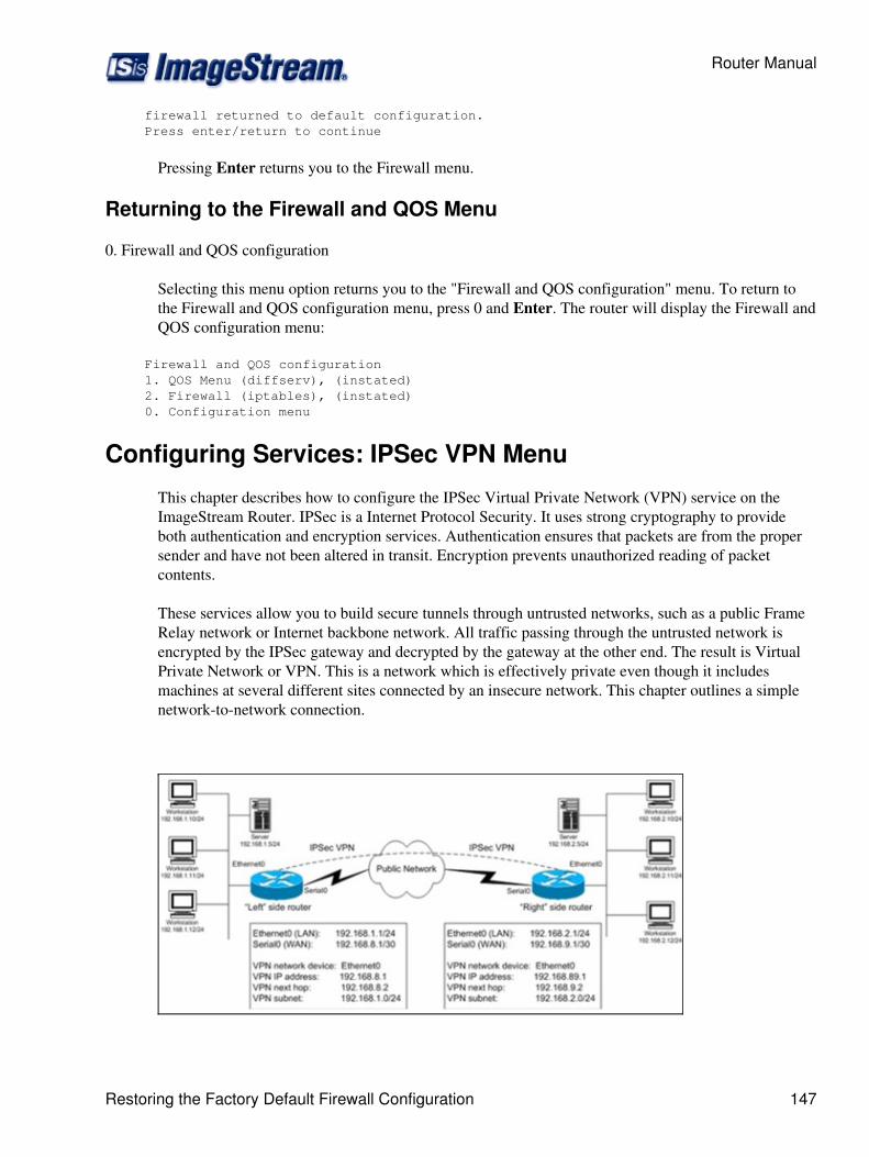
firewall returned to default configuration. Press enter/return to continue
Pressing Enter returns you to the Firewall menu.
Returning to the Firewall and QOS Menu
0. Firewall and QOS configuration
Selecting this menu option returns you to the "Firewall and QOS configuration" menu. To return tothe Firewall and QOS configuration menu, press 0 and Enter. The router will display the Firewall andQOS configuration menu:
Firewall and QOS configuration 1. QOS Menu (diffserv), (instated) 2. Firewall (iptables), (instated) 0. Configuration menu
Configuring Services: IPSec VPN Menu
This chapter describes how to configure the IPSec Virtual Private Network (VPN) service on theImageStream Router. IPSec is a Internet Protocol Security. It uses strong cryptography to provideboth authentication and encryption services. Authentication ensures that packets are from the propersender and have not been altered in transit. Encryption prevents unauthorized reading of packetcontents.
These services allow you to build secure tunnels through untrusted networks, such as a public FrameRelay network or Internet backbone network. All traffic passing through the untrusted network isencrypted by the IPSec gateway and decrypted by the gateway at the other end. The result is VirtualPrivate Network or VPN. This is a network which is effectively private even though it includesmachines at several different sites connected by an insecure network. This chapter outlines a simplenetwork-to-network connection.
Router Manual
Restoring the Factory Default Firewall Configuration 147
More advanced configurations are possible. This chapter includes the following topics:
Configuring the IPSec VPN service◊ Enabling the IPSec VPN service at boot-time◊ Disabling the IPSec VPN service at boot-time◊ Starting the IPSec VPN service◊ Stopping the IPSec VPN service◊
After logging in, the main menu is displayed (your menu may look slightly different):
ISis-Router main menu 1. Configuration menu 2. Show interface status 3. Advanced 4. Router software management 5. Backup/Restore 6. halt/reboot 0. Log off
Select menu option 1, Configuration menu, and press Enter to configure the router. TheConfiguration menu should appear (your menu may look slightly different):
Configuration menu 1. AAA (Password) Configuration 2. Global configuration 3. Network interface configuration 4. Firewall and QOS configuration 5. Service configuration 6. Dynamic routing configuration 7. Save configuration to flash 0. ISis-Router main menu
Select menu optioin 5, Service configuration, and press Enter to configure the router's serviceconfiguration settings. The Service configuration menu will be displayed (again, your menu may lookslightly different):
Service configuration 1. System scheduler (cron), (running) 2. Dialout PPP, (stopped) 3. IPSec VPN (Free S/Wan), (stopped) 4. NetFlow exporter (nprobe), (stopped) 5. network interfaces (sand), (running) 6. sconsole (mgetty), (running) 7. snmp (net-snmp), (stopped) 8. ssh (OpenSSH), (running) 0. Configuration menu
Select menu option 4, IPSec VPN, and press Enter to configure the router's IPSec VPN settings. TheIPSec VPN menu will be displayed (again, your menu may look slightly different):
IPSec VPN (Free S/Wan), (stopped) 1. Configure IPSec (Free S/Wan)
Router Manual
148 Configuring Services: IPSec VPN Menu
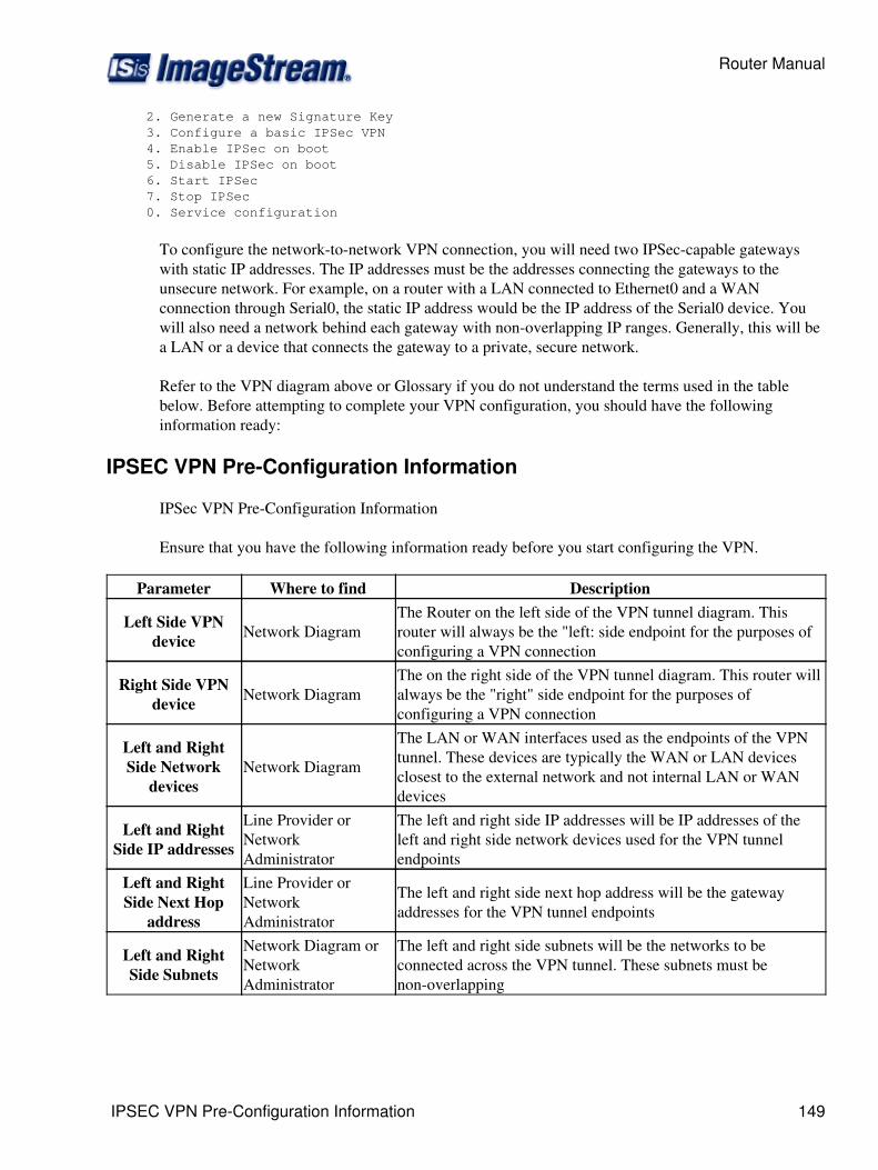
2. Generate a new Signature Key 3. Configure a basic IPSec VPN 4. Enable IPSec on boot 5. Disable IPSec on boot 6. Start IPSec 7. Stop IPSec 0. Service configuration
To configure the network-to-network VPN connection, you will need two IPSec-capable gatewayswith static IP addresses. The IP addresses must be the addresses connecting the gateways to theunsecure network. For example, on a router with a LAN connected to Ethernet0 and a WANconnection through Serial0, the static IP address would be the IP address of the Serial0 device. Youwill also need a network behind each gateway with non-overlapping IP ranges. Generally, this will bea LAN or a device that connects the gateway to a private, secure network.
Refer to the VPN diagram above or Glossary if you do not understand the terms used in the tablebelow. Before attempting to complete your VPN configuration, you should have the followinginformation ready:
IPSEC VPN Pre-Configuration Information
IPSec VPN Pre-Configuration Information
Ensure that you have the following information ready before you start configuring the VPN.
Parameter Where to find Description
Left Side VPNdevice Network Diagram
The Router on the left side of the VPN tunnel diagram. Thisrouter will always be the "left: side endpoint for the purposes ofconfiguring a VPN connection
Right Side VPNdevice Network Diagram
The on the right side of the VPN tunnel diagram. This router willalways be the "right" side endpoint for the purposes ofconfiguring a VPN connection
Left and RightSide Network
devicesNetwork Diagram
The LAN or WAN interfaces used as the endpoints of the VPNtunnel. These devices are typically the WAN or LAN devicesclosest to the external network and not internal LAN or WANdevices
Left and RightSide IP addresses
Line Provider orNetworkAdministrator
The left and right side IP addresses will be IP addresses of theleft and right side network devices used for the VPN tunnelendpoints
Left and RightSide Next Hop
address
Line Provider orNetworkAdministrator
The left and right side next hop address will be the gatewayaddresses for the VPN tunnel endpoints
Left and RightSide Subnets
Network Diagram orNetworkAdministrator
The left and right side subnets will be the networks to beconnected across the VPN tunnel. These subnets must benon-overlapping
Router Manual
IPSEC VPN Pre-Configuration Information 149

Using the Built-in Automated Script to Configure a VPN Tunnel
To configure a simple IPSec VPN, select menu option 3, Configure a basic IPSec VPN, andpressEnter. This will start an interactive script that displays the following:
Now generating a key for this host (May take some time)...done. Please see the ImageStream Technical Support Web site or the ImageStream Router Installation Guide for details on the information requested by this script.
The router will have generated a signature key used to authenticate the VPN connection. The routerwill then display the following:
Will this router be the [L]eft or [R]ight side tunnel endpoint (L/r) ?
Enter the correct side for this router. The left and right side designations are not relative to the router.This router will always be either the left side or right side router. Use your network diagram todetermine whether this router will act as the left or right side router. For example, if you want toconfigure this router as the left side router, enter L and Enter at this prompt.
The router will then ask you to confirm your choice. In the example below, we have accepted thedefault configuration and set this router as the left side router:
This router will be configured as the left side for this IPSec configuration. Is this correct (Y/n) :
If these values are correct, press 'Y' or leave the entry blank and press Enter. If you have made amistake, press 'N' and Enter and the router will reprompt you for the information.
If you pressed 'Y' or 'Enter the following script will be displayed:
Retrieving the public RSA key for this router...done
The router will retrieve the public signature key generated earlier. This key will be used in the IPSecconfiguration file and as part of the authentication process with the other router.
The router will then display:
What interface will this router use as the VPN device (default: Ethernet0) ?
At this prompt, enter the interface you want to use as the VPN device. Typically, this will be thedevice closest to the upstream Internet connection on your network. You can press Enter to acceptthe default value, or enter a device name. For example, to use Serial0 as the VPN device, enterSerial0 at this prompt and press Enter.
The router will then ask you to confirm your choice. In the example below, we have set Serial0 as theVPN device:
This router will use Serial0 as the VPN device for this IPSec configuration. Is this correct (Y/n) :
Router Manual
150 Using the Built-in Automated Script to Configure a VPN Tunnel

If these values are correct, press 'Y' or leave the entry blank and press Enter. If you have made amistake, press 'N' and Enter and the router will reprompt you for the information.
If you pressed 'Y' or Enter, the following script will be displayed:
What is the IP address of Serial0 used for IPSec?
Enter the primary or secondary IP address used for the VPN tunnel endpoint. For example, to use192.168.8.1 as the IP address for this side, enter 192.168.8.1 at this prompt and press Enter.
The router will then ask you to confirm your choice. In the example below, we have entered192.168.8.1:
This router will use 192.168.8.1 as the IP address for this IPSec configuration. Is this correct (Y/n) :
If these values are correct, press 'Y' or leave the entry blank and press Enter. If you have made amistake, press 'N' and Enter and the router will reprompt you for the information.
If you pressed 'Y' or Enter, the following script will be displayed:
What is the next hop address for this router?
Enter the gateway IP address for this VPN tunnel endpoint. This address should be the one used bythe router when traffic leaves the router for the other VPN tunnel endpoint. For example, to use192.168.8.2 as the IP address for this side, enter 192.168.8.2 at this prompt and press Enter.
The router will then ask you to confirm your choice. In the example below, we have entered192.168.8.2:
This router will use 192.168.8.2 as the next hop address for this IPSec configuration. Is this correct (Y/n) :
If these values are correct, press 'Y' or leave the entry blank and press Enter. If you have made amistake, press 'N' and Enter and the router will reprompt you for the information.
The following script will then displayed:
What is the subnet on this router that is to be accessible across the VPN?
For the next question, please enter the value in the format of "ipnetwork/bitmask"
For example, the Class C 192.168.1.x would be entered as 192.168.1.0/24.
Enter the subnet on this router to be accessible across the VPN :
Enter the subnet address for this side of the VPN tunnel. This subnet should be the network you wantto make accessible from the other side of the VPN tunnel. For example, to use 192.168.1.0/24 as thesubnet for this side, enter 192.168.1.0/24 at this prompt and press Enter.
The router will then ask you to confirm your choice. In the example below, we have entered192.168.1.0/24:
Router Manual
Using the Built-in Automated Script to Configure a VPN Tunnel 151
This router will use 192.168.1.0/24 as the subnet on this router to be accessible across the VPN. Is this correct (Y/n) :
If these values are correct, press 'Y' or leave the entry blank and press Enter. If you have made amistake, press 'N' and Enter and the router will reprompt you for the information.
Once you have entered the correct values for the first side, the router will then prompt you for theinformation on the other side of the VPN tunnel. Again, remember that the left and right sidedesignations are not relative to the router. The left side router will always be the left side router andvice versa.
If enter 'Y' or pressed Enter the router will display:
Next, we will enter the values for the right side router...
The router will then prompt you for the identical information for the other side of the VPN tunnel.Please refer to the above section for assistance in answering the questions.
Once you have entered the values for the other endpoint, the router, based on our example, willdisplay:
If the right side router is ImageStream, do you want to attempt to get the right side router's public RSA key automatically? (Y/n) :
If the remote router is ImageStream, you can configure it for the IPSec VPN connectionautomatically. To use this feature, the router you are configuring must have a network connection tothe remote router and the remote router must have a signature key already generated. If you want toattempt to get the remote router's public key, press 'Y' or leave the entry blank and press Enter. If theremote router is not ImageStream, or if you do not have access or a connection to it, press 'N' andEnter and the script will not attempt to automatically configure the remote router.
Auto Configuring a VPN Tunnel on a Remote ImageStream Router
If you have entered Y or left the entry blank and pressed Enter when prompted to get the remoterouter's public RSA key, the router will prompt you for the IP address of the remote router:
Enter the IP address of the right side router :
Enter the IP address of the remote router. This address must be accessible to the local router, and theremote router must have SSH enabled and accessible. If you enter an address that is not accessible, oryour connection hangs, you will have an opportunity to terminate the connection. In the examplebelow, we have entered 192.168.100.140 as the remote router:
Attempting to contact the right side router... Press Control-\ at any time to interrupt the connection process. Attempting to contact the right side router.You will be prompted for the password... Warning: Permanently added '192.168.100.140' (RSA) to the list of known hosts. [email protected]'s password:
Enter the password for the remote router and press Enter. The script will then download the remoterouter's RSA signature key for use in the VPN configuration process. The router will then display
Router Manual
152 Auto Configuring a VPN Tunnel on a Remote ImageStream Router
following, based on our example:
ipsec.secrets 100% |*** ***| 3814 00:00Retrieving the public RSA key for the right side router...done Successfully retrieved public RSA key. Now creating the tunnel configuration for this router...done
If there is an error retrieving the key, either because an incorrect IP address was given or the"ipsec.secrets" file was not located, the router will display the following:
Unable to locate the IPSec keyfile on the right side router. You must generate a key on the remote router! Would you like to try again? (Y/n) :
You can generate an RSA signature key on the remote router, or check the connection to the remoterouter and try again by pressing 'Y' or by leaving the entry blank and pressing Enter. Pressing 'N' andEnter will put the router in manual configuration mode. Please see the section below on manualconfiguration of a VPN tunnel.
The router will then prompt you to configure the remote ImageStream router, assuming that the RSAsignature key was retrieved successfully:
The right side router is an ImageSteam router. Do you want to attempt to configure the right side router also? (Y/n) :
If you want to attempt to configure the remote router for the VPN tunnel, press 'Y' or leave the entryblank and press Enter. If you do not want to configure the remote router, press 'N' and Enter and thescript will not attempt to automatically configure the remote router.
If you pressed 'Y' or Enter the router will then display the following, based on our example:
Now creating the tunnel configuration for the right side router...done Attempting to contact the right side router. You will be prompted for the password... Press Control-\ at any time to interrupt the connection process. [email protected]'s password:
Enter the password for the remote router and press Enter. The script will then upload the proper VPNconfiguration file to the remote router. The router will then display:
ipsec.conf-right 100% |*** *| 1581 00:00Successfully copied the configuration file to the right side router.
You must start the IPSec service before your configuration will be active. Remember to save your configuration to flash, or the changes made in the IPSec configuration file will be lost.
Press enter/return to quit
If you have entered 'N' when prompted to configure the remote router, the script will save a copy ofthe remote configuration and display:
A copy of the configuration file for the right side router has been saved in: /tmp/ipsec.conf-right
You must start the IPSec service before your configuration will be active. Remember to save your configuration to flash, or the changes made in the IPSec configuration file will be lost.
Press enter/return to quit
Router Manual
Auto Configuring a VPN Tunnel on a Remote ImageStream Router 153
If the remote router is an ImageStream router or uses a FreeSwan implementation, you will find acopy of the configuration for that router in the /tmp directory. A copy of the local router'sconfiguration, based on your entries, has been saved on the local router. Using this script does notstart the IPSec service, nor will it enable the service on boot. Use the IPSec menu to start or stopIPSec or to enable or disable the service at boot- time.
Note: You must save the settings to the router's non-volatile flash memory! If the router isrebooted before saving, your changes will be lost! See the Chapter 26, "Manual/Backup/RestoreMenu: Managing Configurations" for more information.
Selecting manual configuration for a VPN tunnel
If you have entered 'N' when prompted to get the remote router's public RSA key, the router willproceed with manual entry of the VPN tunnel configuration and will display the following, based onour example above:
Proceeding with manual entry... Please paste the public key from the right side router. Include only the key and NO other characters When you are finished, press Enter/Return, then press Control-D
Enter the public RSA key only with no other special characters or values. The router willautomatically remove any line breaks from the input. If you are pasting the public key from anotherImageStream router or a FreeSWan implementation, do not include the "pubkey=" when you paste thevalue. If you are using a standard key, it will look similar to:
0sAQNnhVz28e6wHj0IAJzQQiJOTYKfE/+zJbLr86ZbJjfGNMP4gXLm3pf4XFYLCqHbpYYQoYAq1GJiyTUnXe4k0glELTIqLCoM46U6AwRu9g1hA/NSnHPQD2KF+tlwKGYG3tD0pu79q6ks+52p7FO8UzdRxUvSYGtP0bs4XQnB1ZeT8g5uyt7ugmlYZh72W5XeqR7LCji29h5n2rR64WG385TiNPG60VOmyNHHKzhrR0IDs39hgxezNLW4QeVwb4SX6/eYZUXGKv2R56R804OTZ0PyzlYQumMzB/KtUBfbwmAKGBAZTY5ODhwQYVL2LrW/Zg3AAyhkn4lvcEfY8sV316H
The key for your routers will be unique and will not match the above example. Press Enter and thenpress Control-D when you are finished entering the key. The router will then process your input anddisplay the following, based on our example:
Successfully parsed right side public RSA key. Now creating the tunnel configuration for this router...done A copy of the configuration file for the right side router has been saved in: /tmp/ipsec.conf-right
You must start the IPSec service before your configuration will be active. Remember to save your configuration to flash, or the changes made in the IPSec configuration file will be lost.
Press enter/return to quit
If the remote router is an ImageStream router or uses a FreeSwan implementation, you will find acopy of the configuration for that router in the /tmp directory. A copy of the local router'sconfiguration, based on your entries, has been saved on the local router. Using this script does notstart the IPSec service, nor will it enable the service on boot. Use the IPSec menu to start or stopIPSec or to enable or disable the service at boot-time.
Router Manual
154 Selecting manual configuration for a VPN tunnel
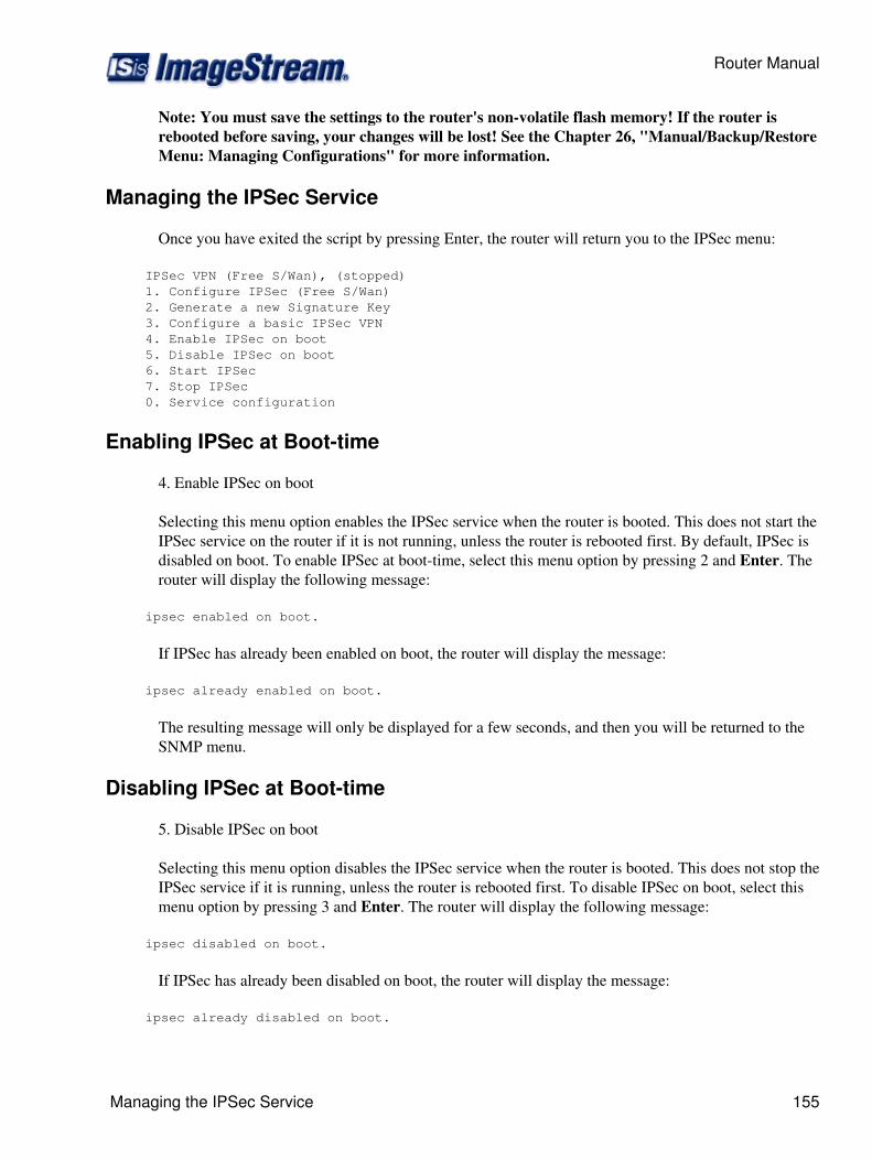
Note: You must save the settings to the router's non-volatile flash memory! If the router isrebooted before saving, your changes will be lost! See the Chapter 26, "Manual/Backup/RestoreMenu: Managing Configurations" for more information.
Managing the IPSec Service
Once you have exited the script by pressing Enter, the router will return you to the IPSec menu:
IPSec VPN (Free S/Wan), (stopped) 1. Configure IPSec (Free S/Wan) 2. Generate a new Signature Key 3. Configure a basic IPSec VPN 4. Enable IPSec on boot 5. Disable IPSec on boot 6. Start IPSec 7. Stop IPSec 0. Service configuration
Enabling IPSec at Boot-time
4. Enable IPSec on boot
Selecting this menu option enables the IPSec service when the router is booted. This does not start theIPSec service on the router if it is not running, unless the router is rebooted first. By default, IPSec isdisabled on boot. To enable IPSec at boot-time, select this menu option by pressing 2 and Enter. Therouter will display the following message:
ipsec enabled on boot.
If IPSec has already been enabled on boot, the router will display the message:
ipsec already enabled on boot.
The resulting message will only be displayed for a few seconds, and then you will be returned to theSNMP menu.
Disabling IPSec at Boot-time
5. Disable IPSec on boot
Selecting this menu option disables the IPSec service when the router is booted. This does not stop theIPSec service if it is running, unless the router is rebooted first. To disable IPSec on boot, select thismenu option by pressing 3 and Enter. The router will display the following message:
ipsec disabled on boot.
If IPSec has already been disabled on boot, the router will display the message:
ipsec already disabled on boot.
Router Manual
Managing the IPSec Service 155

The resulting message will only be displayed for a few seconds, and then you will be returned to theIPSec menu.
Starting the IPSec Service
6. Start IPSec
Selecting this menu option starts the IPSec service on the router. Starting IPSec does notautomatically enable the IPSec service when the router is booted. To start the IPSec service, selectthis menu option by pressing 4 and Enter. The router will display the following message:
Starting ipsec...done.
The message will only be displayed for a few seconds, and then you will be returned to the IPSEcmenu.
Stopping the IPSec Service
7. Stopping IPSec
Selecting this menu option stops the IPSec service on the router. Stopping IPSec does notautomatically disable the IPSec service when the router is booted. To stop the IPSec service, selectthis menu option by pressing 5 and Enter. The router will display the following message:
Stopping ipsec...done.
The message will only be displayed for a few seconds, and then you will be returned to the IPSecmenu.
Returning to the Service Configuration Menu
0. Service configuration
Selecting this menu option returns you to the "Service configuration" menu. To return to the Serviceconfiguration menu, press 0 and Enter. The router will display the Service configuration menu:
Service configuration 1. System scheduler (cron), (running) 2. Dialout PPP, (stopped) 3. IPSec VPN (Free S/Wan), (stopped) 4. NetFlow exporter (nprobe), (stopped) 5. network interfaces (sand), (running) 6. sconsole (mgetty), (running) 7. snmp (net-snmp), (stopped) 8. ssh (OpenSSH), (running) 0. Configuration menu
Router Manual
156 Disabling IPSec at Boot-time
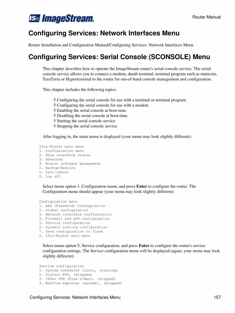
Configuring Services: Network Interfaces Menu
Router Installation and Configuration Manual/Configuring Services: Network Interfaces Menu
Configuring Services: Serial Console (SCONSOLE) Menu
This chapter describes how to operate the ImageStream router's serial console service. The serialconsole service allows you to connect a modem, dumb terminal, terminal program such as minicom,TeraTerm or Hyperterminal to the router for out-of-band console management and configuration.
This chapter includes the following topics:
Configuring the serial console for use with a terminal or terminal program◊ Configuring the serial console for use with a modem◊ Enabling the serial console at boot-time◊ Disabling the serial console at boot-time◊ Starting the serial console service◊ Stopping the serial console service◊
After logging in, the main menu is displayed (your menu may look slightly different):
ISis-Router main menu 1. Configuration menu 2. Show interface status 3. Advanced 4. Router software management 5. Backup/Restore 6. halt/reboot 0. Log off
Select menu option 1, Configuration menu, and press Enter to configure the router. TheConfiguration menu should appear (your menu may look slightly different):
Configuration menu 1. AAA (Password) Configuration 2. Global configuration 3. Network interface configuration 4. Firewall and QOS configuration 5. Service configuration 6. Dynamic routing configuration 7. Save configuration to flash 0. ISis-Router main menu
Select menu option 5, Service configuration, and press Enter to configure the router's serviceconfiguration settings. The Service configuration menu will be displayed (again, your menu may lookslightly different):
Service configuration 1. System scheduler (cron), (running) 2. Dialout PPP, (stopped) 3. IPSec VPN (Free S/Wan), (stopped) 4. NetFlow exporter (nprobe), (stopped)
Router Manual
Configuring Services: Network Interfaces Menu 157
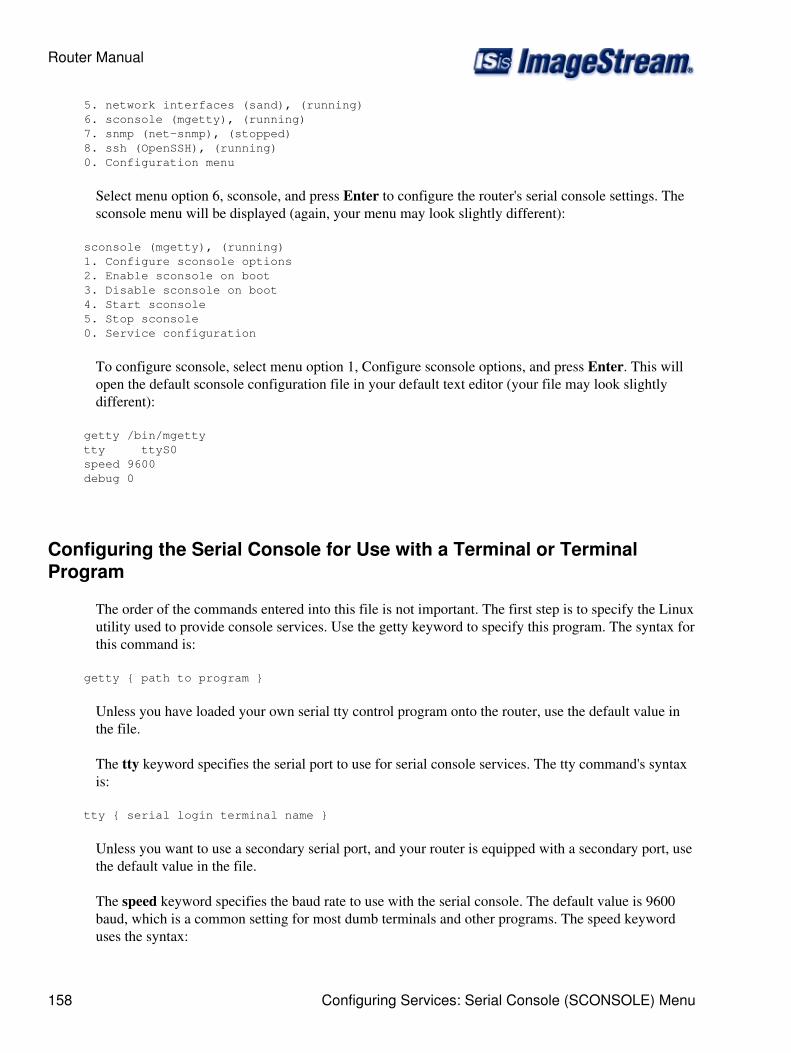
5. network interfaces (sand), (running) 6. sconsole (mgetty), (running) 7. snmp (net-snmp), (stopped) 8. ssh (OpenSSH), (running) 0. Configuration menu
Select menu option 6, sconsole, and press Enter to configure the router's serial console settings. Thesconsole menu will be displayed (again, your menu may look slightly different):
sconsole (mgetty), (running) 1. Configure sconsole options 2. Enable sconsole on boot 3. Disable sconsole on boot 4. Start sconsole 5. Stop sconsole 0. Service configuration
To configure sconsole, select menu option 1, Configure sconsole options, and press Enter. This willopen the default sconsole configuration file in your default text editor (your file may look slightlydifferent):
getty /bin/mgetty tty ttyS0 speed 9600 debug 0
Configuring the Serial Console for Use with a Terminal or TerminalProgram
The order of the commands entered into this file is not important. The first step is to specify the Linuxutility used to provide console services. Use the getty keyword to specify this program. The syntax forthis command is:
getty { path to program }
Unless you have loaded your own serial tty control program onto the router, use the default value inthe file.
The tty keyword specifies the serial port to use for serial console services. The tty command's syntaxis:
tty { serial login terminal name }
Unless you want to use a secondary serial port, and your router is equipped with a secondary port, usethe default value in the file.
The speed keyword specifies the baud rate to use with the serial console. The default value is 9600baud, which is a common setting for most dumb terminals and other programs. The speed keyworduses the syntax:
Router Manual
158 Configuring Services: Serial Console (SCONSOLE) Menu
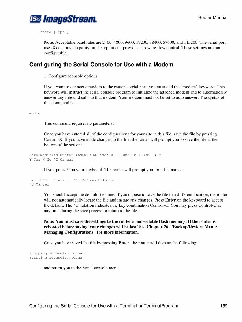
speed { bps }
Note: Acceptable baud rates are 2400, 4800, 9600, 19200, 38400, 57600, and 115200. The serial portuses 8 data bits, no parity bit, 1 stop bit and provides hardware flow control. These settings are notconfigurable.
Configuring the Serial Console for Use with a Modem
1. Configure sconsole options
If you want to connect a modem to the router's serial port, you must add the "modem" keyword. Thiskeyword will instruct the serial console program to initialize the attached modem and to automaticallyanswer any inbound calls to that modem. Your modem must not be set to auto answer. The syntax ofthis command is:
modem
This command requires no parameters.
Once you have entered all of the configurations for your site in this file, save the file by pressingControl-X. If you have made changes to the file, the router will prompt you to save the file at thebottom of the screen:
Save modified buffer (ANSWERING "No" WILL DESTROY CHANGES) ?Y Yes N No ^C Cancel
If you press Y on your keyboard. The router will prompt you for a file name:
File Name to write: /etc/sconsoled.conf^C Cancel
You should accept the default filename. If you choose to save the file in a different location, the routerwill not automatically locate the file and instate any changes. Press Enter on the keyboard to acceptthe default. The ^C notation indicates the key combination Control-C. You may press Control-C atany time during the save process to return to the file.
Note: You must save the settings to the router's non-volatile flash memory! If the router isrebooted before saving, your changes will be lost! See Chapter 26, "Backup/Restore Menu:Managing Configurations" for more information.
Once you have saved the file by pressing Enter, the router will display the following:
Stopping sconsole...done Starting sconsole...done
and return you to the Serial console menu.
Router Manual
Configuring the Serial Console for Use with a Terminal or TerminalProgram 159
Enabling the Serial Console at Boot-time
2. Enable sconsole on boot
Selecting this menu option enables the serial console when the router is booted. This does not start theserial console service on the router if it is not running, unless the router is first rebooted. By default,the serial console is enabled on boot. To enable the serial console boot, select this menu option bypressing 2 and Enter. The router will display the following message:
sconsole enabled on boot.
If the serial console has already been enabled on boot, the router will display the message:
sconsole already enabled on boot.
The resulting message will only be displayed for a few seconds, and then you will be returned to theSerial console menu.
Disabling the Serial Console at Boot-time
3. Disable sconsole on boot
Selecting this menu option disables the serial console when the router is booted. This does not stopthe serial console service if it is running, unless the router is first rebooted. To disable the serialconsole on boot, select this menu option by pressing 3 and Enter. The router will display thefollowing message:
sconsole disabled on boot.
If the serial console has already been disabled on boot, the router will display the message:
sconsole already disabled on boot.
The resulting message will only be displayed for a few seconds, and then you will be returned to theSerial console menu.
Starting the Serial Console Service
4. Start sconsole
Selecting this menu option starts the serial console service on the router. Starting the serial consoledoes not automatically enable the serial console when the router is booted. To start the serial consoleservice, select this menu option by pressing 4 and Enter. The router will display the followingmessage:
Starting sconsole...done.
The message will only be displayed for a few seconds, and then you will be returned to the Serialconsole menu.
Router Manual
160 Enabling the Serial Console at Boot-time
Stopping the Serial Console Service
5. Stopping sconsole
Selecting this menu option stops the serial console service on the router. Stopping the serial consoleconfiguration does not automatically disable the serial console when the router is booted. To stop theserial console service, select this menu option by pressing 5 and Enter. The router will display thefollowing message:
Stopping sconsole...done.
The message will only be displayed for a few seconds, and then you will be returned to the Serialconsole menu.
Returning to the Service Configuration Menu
0. Service configuration
Selecting this menu option returns you to the "Service configuration" menu. To return to the Serviceconfiguration menu, press 0 and Enter. The router will display the Service configuration menu:
Service configuration 1. System scheduler (cron), (running) 2. Dialout PPP, (stopped) 3. IPSec VPN (Free S/Wan), (stopped) 4. NetFlow exporter (nprobe), (stopped) 5. network interfaces (sand), (running) 6. sconsole (mgetty), (running) 7. snmp (net-snmp), (stopped) 8. ssh (OpenSSH), (running) 0. Configuration menu
Configuring Services: SNMP Menu
This chapter describes how to configure the Simple Network Management Protocol (SNMP) serviceon the ImageStream router. The SNMP service allows you to access link status, traffic andconfiguration information via a standard MIB-II-compliant SNMP interface. The simple networkmanagement protocol (SNMP) is an application-layer protocol that allows devices to communicatemanagement information. This chapter describes the basic configuration of the syslocation, syscontactand community variables. More advanced configurations are possible.
SNMP Menu
After logging in, the main menu is displayed (your menu may look slightly different):
Router main menu 1. Configuration menu 2. Show interface status 3. Advanced 4. Router software management
Router Manual
Stopping the Serial Console Service 161
5. Backup/Restore 6. halt/reboot 0. Log off
Select menu option 1, Configuration and update menu, and press Enter to configure the router. TheConfiguration menu should appear (your menu may look slightly different):
Configuration menu 1. AAA (Password) Configuration 2. Global configuration 3. Network interface configuration 4. Firewall and QOS configuration 5. Service configuration 6. Dynamic routing configuration 7. Save configuration to flash 0. Router main menu
Select menu option 5, Service configuration, and press Enter to configure the router's serviceconfiguration settings. The Service configuration menu will be displayed (again, your menu may lookslightly different):
Service configuration 1. System scheduler (cron), (running) 2. Dialout PPP, (stopped) 3. IPSec VPN (Free S/Wan), (stopped) 4. NetFlow exporter (nprobe), (stopped) 5. network interfaces (sand), (running) 6. sconsole (mgetty), (running) 7. snmp (net-snmp), (stopped) 8. ssh (OpenSSH), (running) 0. Configuration menu
Select menu option 7, snmp, and press Enter to configure the router's SNMP settings. The snmpmenu will be displayed (again, your menu may look slightly different):
snmp, (running) 1. Configure snmp (net-snmp) 2. Enable snmp on boot (Does not start snmp) 3. Disable snmp on boot (Does not kill snmp) 4. Start snmp 5. Stop snmp 0. Service configuration
To configure SNMP, select menu option 1, Configure snmp, and press Enter. This will open thedefault SNMP configuration file in your default text editor (your file may look slightly different):
# # snmpd.conf # # - created by the snmpconf configuration program## SECTION: System Information Setup # # This section defines some of the information reported in# the "system" mib group in the mibII tree. # syslocation: The [typically physical] location of the system.
Router Manual
162 SNMP Menu

# arguments: location_string syslocation Unknown # syscontact: The contact information for the administrator# arguments: contact_string syscontact root@localhost # SECTION: Access Control Setup # # This section defines who is allowed to talk to your running# snmp agent. # rocommunity: a SNMPv1/SNMPv2c read-only access community name# arguments: community [default|hostname|network/bits] [oid] rocommunity public
Configuring the SNMP Service
Simple Network Management Protocol (SNMP) monitoring is used to set and collect information onSNMP-capable devices. This feature is most often used to monitor network statistics such as usageand error rate. If SNMP monitoring is on, the router accepts SNMP queries. If SNMP monitoring isoff, all SNMP queries are ignored.
The order of the commands entered into this file is not important. The first step is to set the locationvariable used by SNMP. This is an optional variable that can be used to identify location,configuration or other information about the system when it is queried via SNMP. The systemlocation variable does not affect the operation of SNMP or the router. Use the syslocation keyword tospecify this value. The syntax for this command is:
syslocation { string }
The first part of the entry (syslocation) specifies the variable to be set. The second (string) part is thevalue of the variable. The length of this value should not exceed 256 characters. If more than a singleword is used, the value must be quoted. For example:
syslocation "Co-Lo Row 3, Rack 4"
The syscontact keyword typically specifies the e-mail address, telephone number or other contactresponsible for the system. This keyword is also optional and can be up to 256 characters in length.The syscontact command's syntax is:
syscontact { string }
If more than a single word is used, the value must be quoted. For example:
syscontact "root@localhost Joe Smith 800-555-1212"
Configuring the SNMP Community String
Community strings allow you to control access to the MIB information on selected SNMP devices.The read community strings acts like a simple password to permit access to the SNMP agentinformation. Any device that is allowed to read or access the MIB information must know thecommunity string specified in the SNMP configuration file. The default read community string ispublic. The command syntax is:
Router Manual
Configuring the SNMP Service 163
rocommunity { string }
Again, the string may be up to 256 characters and should be limited to a single word. Some SNMPreaders do not support community names with space or other nonprintable characters. For example:
rocommunity router
this sets the read community string to router.
Enabling Trap Generation
SNMP v1 and v2 traps can be sent to a monitoring system when critical system events occur such asnetwork interface state changes. To enable SNMP traps some additional parameters must be set.
trapcommunity { string }
This sets the community to send traps to.
agentSecName { string } rwuser { string }
These add a user for sending v2 traps.
trapsink { ip address }
The trapsink command specifies v1 traps should be sent to the ip address.
trap2sink { ip address }
The trap2sink command specifies v2 traps should be sent to the ip address.
defaultMonitors yes
Enable default monitoring for trap generation.
linkUpDownNotifications yes
Generate traps when network interfaces go up/down.
SNMP version 2 trap example
trapcommunity public trap2sink 5.5.5.2 agentSecName _internal rwuser _internal # Activate the standard monitoring entries defaultMonitors yes linkUpDownNotifications yes
More information on active monitoring and trap generation is available from the Net-snmpmaintainers at http://net-snmp.sourceforge.net/docs/man/snmpd.examples.html#lbAT.
Router Manual
164 Configuring the SNMP Community String
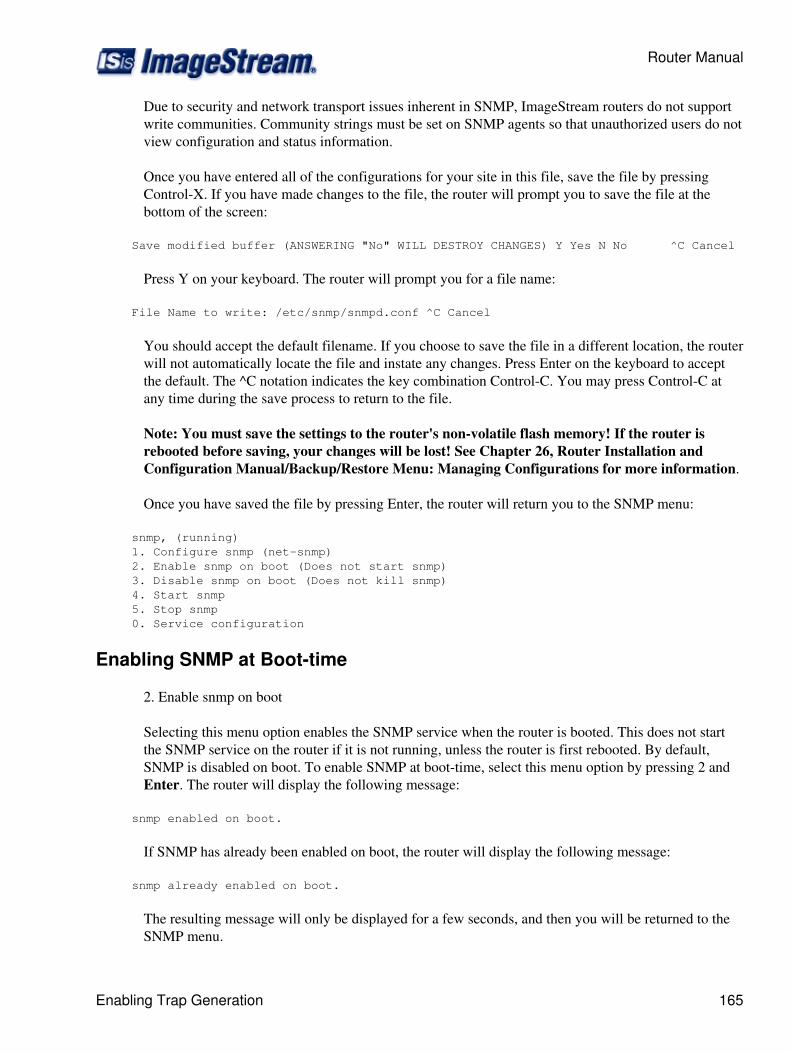
Due to security and network transport issues inherent in SNMP, ImageStream routers do not supportwrite communities. Community strings must be set on SNMP agents so that unauthorized users do notview configuration and status information.
Once you have entered all of the configurations for your site in this file, save the file by pressingControl-X. If you have made changes to the file, the router will prompt you to save the file at thebottom of the screen:
Save modified buffer (ANSWERING "No" WILL DESTROY CHANGES) Y Yes N No ^C Cancel
Press Y on your keyboard. The router will prompt you for a file name:
File Name to write: /etc/snmp/snmpd.conf ^C Cancel
You should accept the default filename. If you choose to save the file in a different location, the routerwill not automatically locate the file and instate any changes. Press Enter on the keyboard to acceptthe default. The ^C notation indicates the key combination Control-C. You may press Control-C atany time during the save process to return to the file.
Note: You must save the settings to the router's non-volatile flash memory! If the router isrebooted before saving, your changes will be lost! See Chapter 26, Router Installation andConfiguration Manual/Backup/Restore Menu: Managing Configurations for more information.
Once you have saved the file by pressing Enter, the router will return you to the SNMP menu:
snmp, (running) 1. Configure snmp (net-snmp) 2. Enable snmp on boot (Does not start snmp) 3. Disable snmp on boot (Does not kill snmp) 4. Start snmp 5. Stop snmp 0. Service configuration
Enabling SNMP at Boot-time
2. Enable snmp on boot
Selecting this menu option enables the SNMP service when the router is booted. This does not startthe SNMP service on the router if it is not running, unless the router is first rebooted. By default,SNMP is disabled on boot. To enable SNMP at boot-time, select this menu option by pressing 2 andEnter. The router will display the following message:
snmp enabled on boot.
If SNMP has already been enabled on boot, the router will display the following message:
snmp already enabled on boot.
The resulting message will only be displayed for a few seconds, and then you will be returned to theSNMP menu.
Router Manual
Enabling Trap Generation 165
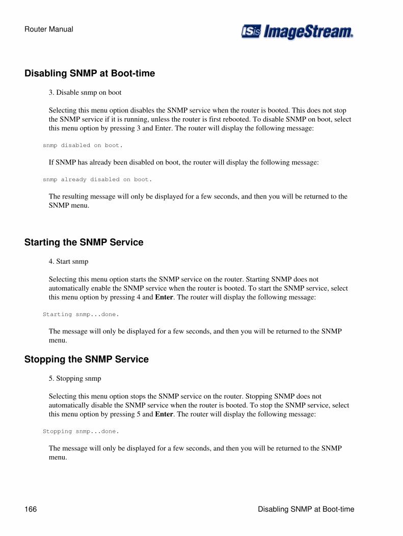
Disabling SNMP at Boot-time
3. Disable snmp on boot
Selecting this menu option disables the SNMP service when the router is booted. This does not stopthe SNMP service if it is running, unless the router is first rebooted. To disable SNMP on boot, selectthis menu option by pressing 3 and Enter. The router will display the following message:
snmp disabled on boot.
If SNMP has already been disabled on boot, the router will display the following message:
snmp already disabled on boot.
The resulting message will only be displayed for a few seconds, and then you will be returned to theSNMP menu.
Starting the SNMP Service
4. Start snmp
Selecting this menu option starts the SNMP service on the router. Starting SNMP does notautomatically enable the SNMP service when the router is booted. To start the SNMP service, selectthis menu option by pressing 4 and Enter. The router will display the following message:
Starting snmp...done.
The message will only be displayed for a few seconds, and then you will be returned to the SNMPmenu.
Stopping the SNMP Service
5. Stopping snmp
Selecting this menu option stops the SNMP service on the router. Stopping SNMP does notautomatically disable the SNMP service when the router is booted. To stop the SNMP service, selectthis menu option by pressing 5 and Enter. The router will display the following message:
Stopping snmp...done.
The message will only be displayed for a few seconds, and then you will be returned to the SNMPmenu.
Router Manual
166 Disabling SNMP at Boot-time
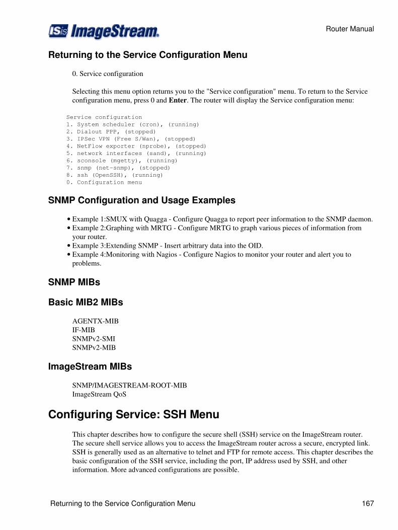
Returning to the Service Configuration Menu
0. Service configuration
Selecting this menu option returns you to the "Service configuration" menu. To return to the Serviceconfiguration menu, press 0 and Enter. The router will display the Service configuration menu:
Service configuration 1. System scheduler (cron), (running) 2. Dialout PPP, (stopped) 3. IPSec VPN (Free S/Wan), (stopped) 4. NetFlow exporter (nprobe), (stopped) 5. network interfaces (sand), (running) 6. sconsole (mgetty), (running) 7. snmp (net-snmp), (stopped) 8. ssh (OpenSSH), (running) 0. Configuration menu
SNMP Configuration and Usage Examples
Example 1:SMUX with Quagga - Configure Quagga to report peer information to the SNMP daemon.• Example 2:Graphing with MRTG - Configure MRTG to graph various pieces of information fromyour router.
•
Example 3:Extending SNMP - Insert arbitrary data into the OID.• Example 4:Monitoring with Nagios - Configure Nagios to monitor your router and alert you toproblems.
•
SNMP MIBs
Basic MIB2 MIBs
AGENTX-MIBIF-MIBSNMPv2-SMISNMPv2-MIB
ImageStream MIBs
SNMP/IMAGESTREAM-ROOT-MIBImageStream QoS
Configuring Service: SSH Menu
This chapter describes how to configure the secure shell (SSH) service on the ImageStream router.The secure shell service allows you to access the ImageStream router across a secure, encrypted link.SSH is generally used as an alternative to telnet and FTP for remote access. This chapter describes thebasic configuration of the SSH service, including the port, IP address used by SSH, and otherinformation. More advanced configurations are possible.
Router Manual
Returning to the Service Configuration Menu 167
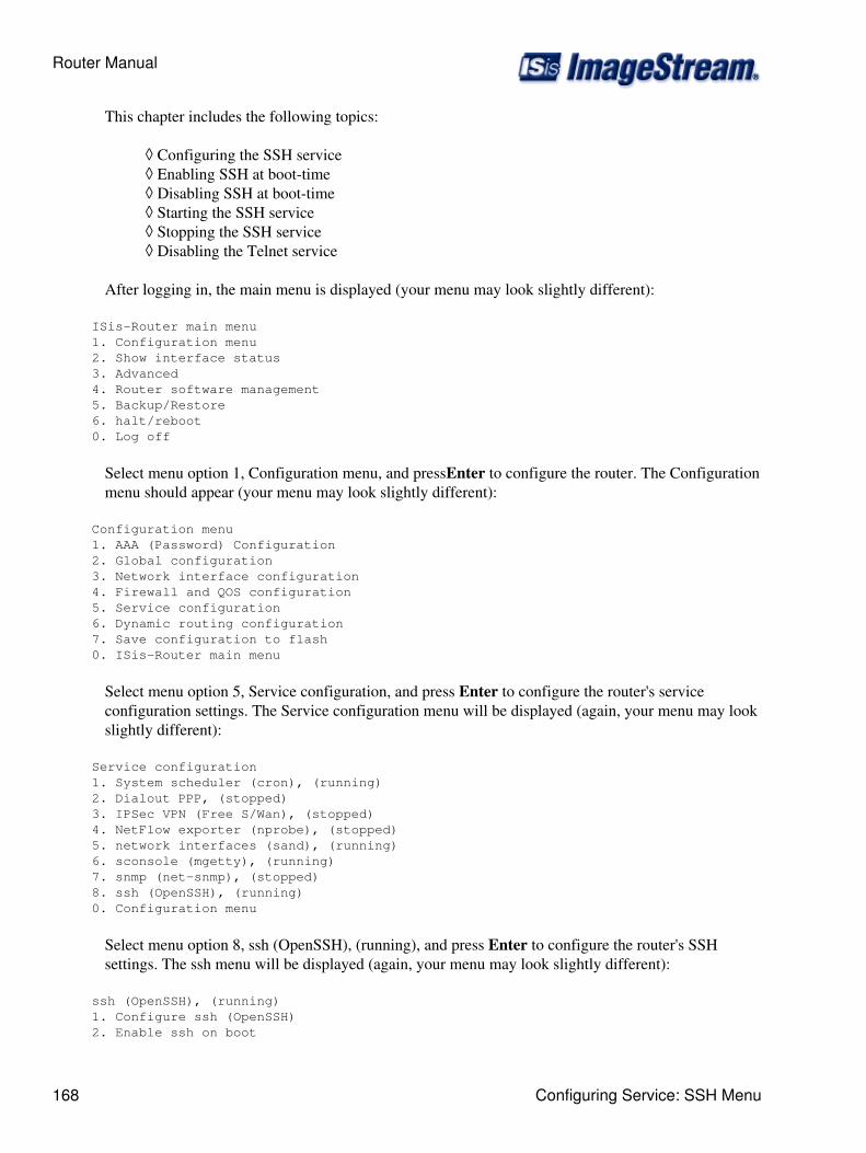
This chapter includes the following topics:
Configuring the SSH service◊ Enabling SSH at boot-time◊ Disabling SSH at boot-time◊ Starting the SSH service◊ Stopping the SSH service◊ Disabling the Telnet service◊
After logging in, the main menu is displayed (your menu may look slightly different):
ISis-Router main menu 1. Configuration menu 2. Show interface status 3. Advanced 4. Router software management 5. Backup/Restore 6. halt/reboot 0. Log off
Select menu option 1, Configuration menu, and pressEnter to configure the router. The Configurationmenu should appear (your menu may look slightly different):
Configuration menu 1. AAA (Password) Configuration 2. Global configuration 3. Network interface configuration 4. Firewall and QOS configuration 5. Service configuration 6. Dynamic routing configuration 7. Save configuration to flash 0. ISis-Router main menu
Select menu option 5, Service configuration, and press Enter to configure the router's serviceconfiguration settings. The Service configuration menu will be displayed (again, your menu may lookslightly different):
Service configuration 1. System scheduler (cron), (running) 2. Dialout PPP, (stopped) 3. IPSec VPN (Free S/Wan), (stopped) 4. NetFlow exporter (nprobe), (stopped) 5. network interfaces (sand), (running) 6. sconsole (mgetty), (running) 7. snmp (net-snmp), (stopped) 8. ssh (OpenSSH), (running) 0. Configuration menu
Select menu option 8, ssh (OpenSSH), (running), and press Enter to configure the router's SSHsettings. The ssh menu will be displayed (again, your menu may look slightly different):
ssh (OpenSSH), (running) 1. Configure ssh (OpenSSH) 2. Enable ssh on boot
Router Manual
168 Configuring Service: SSH Menu
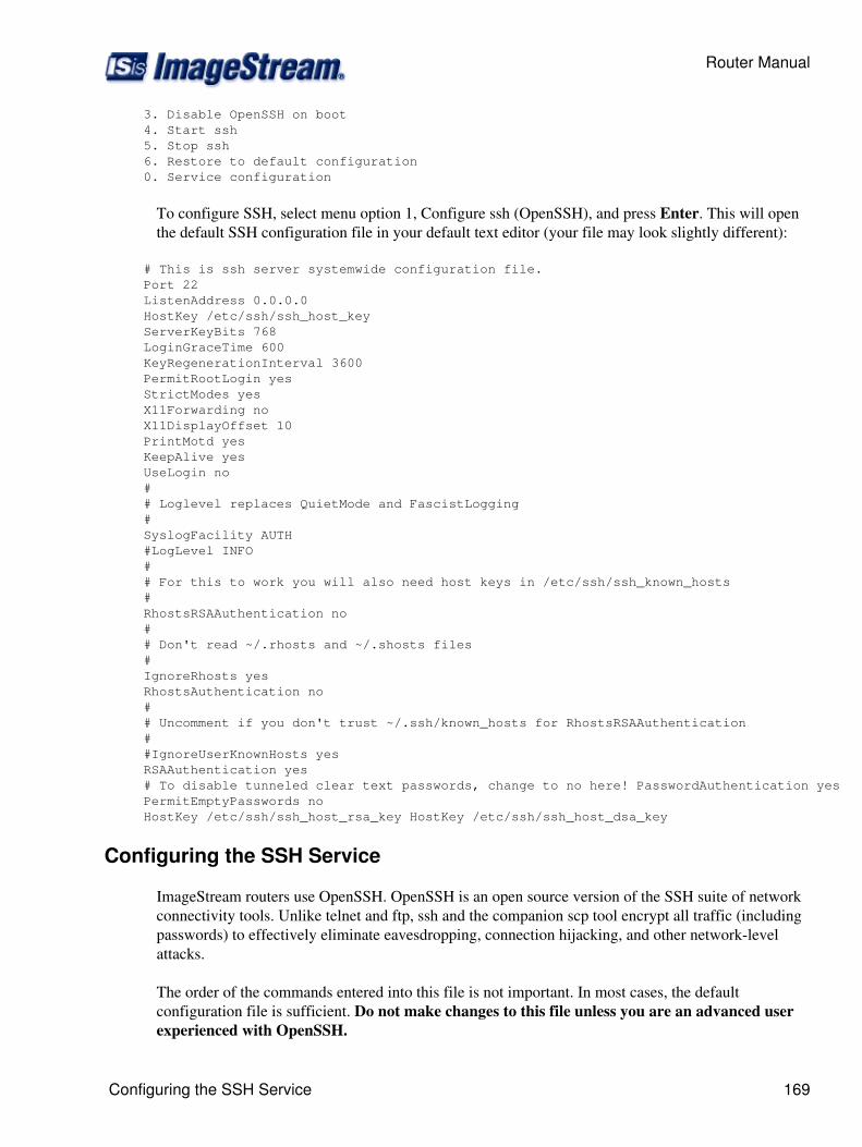
3. Disable OpenSSH on boot 4. Start ssh 5. Stop ssh 6. Restore to default configuration 0. Service configuration
To configure SSH, select menu option 1, Configure ssh (OpenSSH), and press Enter. This will openthe default SSH configuration file in your default text editor (your file may look slightly different):
# This is ssh server systemwide configuration file. Port 22 ListenAddress 0.0.0.0 HostKey /etc/ssh/ssh_host_key ServerKeyBits 768 LoginGraceTime 600 KeyRegenerationInterval 3600 PermitRootLogin yes StrictModes yes X11Forwarding no X11DisplayOffset 10 PrintMotd yes KeepAlive yes UseLogin no # # Loglevel replaces QuietMode and FascistLogging # SyslogFacility AUTH #LogLevel INFO # # For this to work you will also need host keys in /etc/ssh/ssh_known_hosts # RhostsRSAAuthentication no # # Don't read ~/.rhosts and ~/.shosts files # IgnoreRhosts yes RhostsAuthentication no # # Uncomment if you don't trust ~/.ssh/known_hosts for RhostsRSAAuthentication # #IgnoreUserKnownHosts yes RSAAuthentication yes # To disable tunneled clear text passwords, change to no here! PasswordAuthentication yes PermitEmptyPasswords no HostKey /etc/ssh/ssh_host_rsa_key HostKey /etc/ssh/ssh_host_dsa_key
Configuring the SSH Service
ImageStream routers use OpenSSH. OpenSSH is an open source version of the SSH suite of networkconnectivity tools. Unlike telnet and ftp, ssh and the companion scp tool encrypt all traffic (includingpasswords) to effectively eliminate eavesdropping, connection hijacking, and other network-levelattacks.
The order of the commands entered into this file is not important. In most cases, the defaultconfiguration file is sufficient. Do not make changes to this file unless you are an advanced userexperienced with OpenSSH.
Router Manual
Configuring the SSH Service 169
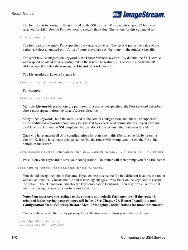
The first step is to configure the port used by the SSH service. By convention, port 22 has beenreserved for SSH. Use the Port keyword to specify this value. The syntax for this command is:
Port { number }
The first part of the entry (Port) specifies the variable to be set. The second part is the value of thevariable. Select an unused port. A list of ports is available on the router in the /etc/services file.
The other basic configuration keyword is the ListenAddress keyword. By default, the SSH servicewill respond on all addresses configured on the router. To restrict SSH access to a particular IPaddress, specify that address using the ListenAddress keyword.
The ListenAddress keyword syntax is:
ListenAddress { IP address } : [ port ]
For example:
ListenAddress 192.168.100.1
Multiple ListenAddress options are permitted. If a port is not specified, the Port keyword describedabove must appear before the ListenAddress directive.
Many other keywords, both the ones listed in the default configuration and others, are supported.These additional keywords should only be adjusted by experienced administrators. If you have notused OpenSSH or similar SSH implementations, do not change any other values in this file.
Once you have entered all of the configurations for your site in this file, save the file by pressingControl-X. If you have made changes to the file, the router will prompt you to save the file at thebottom of the screen:
Save modified buffer (ANSWERING "No" WILL DESTROY CHANGES) ? Y Yes N No ^C Cancel
Press Y on your keyboard to save your configuration. The router will then prompt you for a file name:
File Name to write: /etc/ssh/sshd_config ^C Cancel
You should accept the default filename. If you choose to save the file in a different location, the routerwill not automatically locate the file and instate any changes. Press Enter on the keyboard to acceptthe default. The ^C notation indicates the key combination Control-C. You may press Control-C atany time during the save process to return to the file.
Note: You must save the settings to the router's non-volatile flash memory! If the router isrebooted before saving, your changes will be lost! See Chapter 26, Router Installation andConfiguration Manual/Backup/Restore Menu: Managing Configurations for more information.
Once you have saved the file by pressing Enter, the router will return you to the SSH menu:
ssh (OpenSSH), (running) 1. Configure ssh (OpenSSH)
Router Manual
170 Configuring the SSH Service
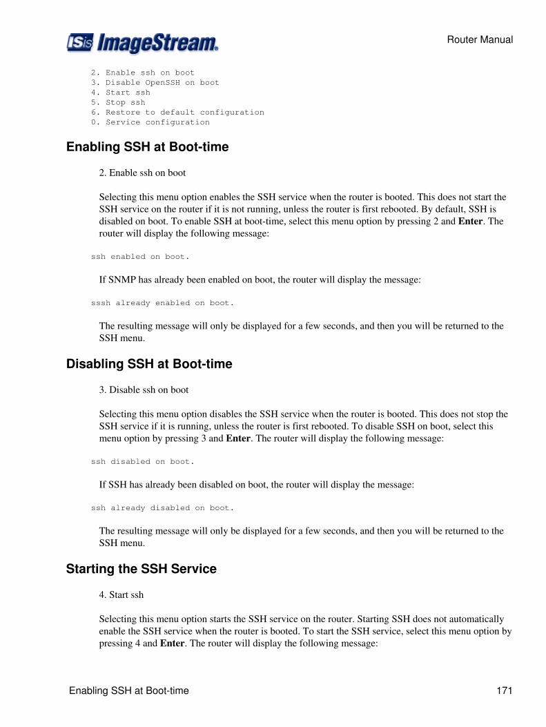
2. Enable ssh on boot 3. Disable OpenSSH on boot 4. Start ssh 5. Stop ssh 6. Restore to default configuration 0. Service configuration
Enabling SSH at Boot-time
2. Enable ssh on boot
Selecting this menu option enables the SSH service when the router is booted. This does not start theSSH service on the router if it is not running, unless the router is first rebooted. By default, SSH isdisabled on boot. To enable SSH at boot-time, select this menu option by pressing 2 and Enter. Therouter will display the following message:
ssh enabled on boot.
If SNMP has already been enabled on boot, the router will display the message:
sssh already enabled on boot.
The resulting message will only be displayed for a few seconds, and then you will be returned to theSSH menu.
Disabling SSH at Boot-time
3. Disable ssh on boot
Selecting this menu option disables the SSH service when the router is booted. This does not stop theSSH service if it is running, unless the router is first rebooted. To disable SSH on boot, select thismenu option by pressing 3 and Enter. The router will display the following message:
ssh disabled on boot.
If SSH has already been disabled on boot, the router will display the message:
ssh already disabled on boot.
The resulting message will only be displayed for a few seconds, and then you will be returned to theSSH menu.
Starting the SSH Service
4. Start ssh
Selecting this menu option starts the SSH service on the router. Starting SSH does not automaticallyenable the SSH service when the router is booted. To start the SSH service, select this menu option bypressing 4 and Enter. The router will display the following message:
Router Manual
Enabling SSH at Boot-time 171
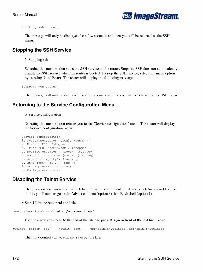
Starting ssh...done.
The message will only be displayed for a few seconds, and then you will be returned to the SSHmenu.
Stopping the SSH Service
5. Stopping ssh
Selecting this menu option stops the SSH service on the router. Stopping SSH does not automaticallydisable the SSH service when the router is booted. To stop the SSH service, select this menu optionby pressing 5 and Enter. The router will display the following message:
Stopping ssh...done.
The message will only be displayed for a few seconds, and the you will be returned to the SSH menu.
Returning to the Service Configuration Menu
0. Service configuration
Selecting this menu option returns you to the "Service configuration" menu. The router will displaythe Service configuration menu:
Service configuration 1. System scheduler (cron), (running) 2. Dialout PPP, (stopped) 3. IPSec VPN (Free S/Wan), (stopped) 4. NetFlow exporter (nprobe), (stopped) 5. network interfaces (sand), (running) 6. sconsole (mgetty), (running) 7. snmp (net-snmp), (stopped) 8. ssh (OpenSSH), (running) 0. Configuration menu
Disabling the Telnet Service
There is no service menu to disable telnet. It has to be commented out via the /etc/inetd.conf file. Todo this you'll need to go to the Advanced menu (option 3) then Bash shell (option 1).
Step 1 Edit the /etc/inetd.conf file:•
router:/usr/local/sand# pico /etc/inetd.conf
Use the arrow keys to go to the end of the file and put a '#' sign in front of the last line like so:
#telnet stream tcp nowait root /usr/sbin/in.telnetd /usr/sbin/in.telnetd
Then hit <control - x> to exit and save out the file.
Router Manual
172 Starting the SSH Service
Step 2 Restart inetd:•
router:/usr/local/sand# killall -HUP inetd
Configuring_CALEA_Intercepts
ImageStream's CALEA architecture has three basic components. Intercept management tasks are performedby the Inetics Configmgr process. Each intercept has a tap process to capture data and deliver the informationto an lea_collector process for local storage or delivery to a Trusted Third Party or Law Enforcement Agency.
Several new scripts and Inetics wan.conf commands were added to the 4.2.10-11 release to support CALEAintercepts. Intercept configuration is handled by the "tap_edit" script. This script stores the confidentialinformation for each intercept in an encrypted file. Configmgr uses a new wan.conf command called "run" torun the "tap_run" script which decrypts the intercept configuration file and runs the tap process. The tapprocess uses libpcap and standard pcap/tcpdump filters to capture data. The data is then delivered to anlea_collector process via a UDP socket and a custom packet format. The lea_collector process can store thedata to a pcap/tcpdump file and/or retransmit the original packet on another network interface/VPN tofacilitate delivery to a Trusted Third Party or Law Enforcement Agency. The lea_collector cannot be run onthe router if pcap file storage is required. ImageStream has a special arrangement with Intelleq which allowsImageStream routers to deliver i ntercept data without running the lea_collector on the router.
Detailed command syntax:
The command syntax for the tap is:
tap -i interface -x content-id -y case-id -z iap-system-id [-d dest-ip] [-c] [-m cmc-port] [-n cmii-port] [-fcapture-filter]
The interface should be the interface to listen in on. Content-id, case-id, iap-system-id are assigned by theLEA. This setup will not use these IDs since they're only transmitted in the CMII stream. Only the CMC fullpacket capture is used. the dest-ip is the IP address of the collector.
The CMC port is assigned by you. The capture-filter is a tcpdump style filter. In most cases we'll use a host<IP> filter, an ether host <MAC> filter or both.
To provide confidentiality the tap_edit and tap_run scripts can be used to keep each intercept configurationin a separate encrypted file in the /etc/taps directory.
The tap_edit script accepts a filename as its argument. Each intercept should be given a unique filename. Thescript takes care of decryption and encryption.
tap_edit filename
The configuration file uses the same arguments as the tap command line. Each argument needs to be placedon a separate line:
-i interface -x content-id -y case-id -z iap-system-id -d dest-ip -c -m cmc-port -n cmii-port -f capture-filter
Router Manual
Disabling the Telnet Service 173
The "tap_run" script is needed to decrypt the configuration file and invoke the tap program. This script shouldbe run using the wan.conf "run" command.
run tap_run filename
For the collector side:
The command syntax for the collector is:
lea_collector -t cmii-capture-file [-f capture-file> [-m cmc-port] [-n cmii-port] [-x cooked-format] [-ooutput interface]
Capture files should not be specified on a router without an attached hard drive to avoid filling up the ramdisk.Instead routers should use the -o option to mirror the incoming CMC data to the specified output interface.
The CMII summary data is not used - only the actual CMC packet content is redirected to the output interface.
Cooked format is never used.
Complete 2 client example:
Clients will connect to the collector router using OpenVPN client/server mode and will be given dynamicallyassigned IPs starting with 192.168.99.2 through 192.168.99.254. Each client will be assigned a uniqueusername/password combination to allow connection to the VPN.
Clients will transmit CMC data (full packet captures) to the collector router on incrementing port numbersstarting at 6001. Client 2 will use 6002 for its port, etc. CMII summary data will be transmitted onincrementing port numbers starting at 7001. This data will be sent over the OpenVPN encrypted tunnel to thecollector router at 192.168.99.1.
Router 1 (collector) wan.conf file:
interface Ethernet0 description Internet facing interface ip address <your IP and netmask>!interface Ethernet1 description LEA collector facing interface no ip address!interface Tunnel0 description Encrypted tunnel to clients tunnel mode openvpn server 192.168.99.0 255.255.255.0 tunnel options --dev-type tap ip address 192.168.99.1 255.255.255.0!ip route 0.0.0.0 0.0.0.0 <your default gateway>
Router Manual
174 Detailed command syntax:
!# Put OpenVPN users/passwords hereuser client1 password clientpassword1user client2 password clientpassword2!# Commands to run a collector process for each client and redirect the output to eth1 (Ethernet1)run lea_collection -m 6001 -n 7001 -o eth1run lea_collection -m 6002 -n 7002 -o eth1
Client 1 LEA assigned content-id: 1234, case-id: 5678, iap-system-id: 9999 Intercept target IP is 86.55.21.253
wan.conf file:
interface Ethernet0 description Internet facing interface ip address <client 1's IP and netmask>!interface Ethernet1 description Tap facing interface no ip address!interface Tunnel0 tunnel mode openvpn client username client1 password clientpassword1 tunnel destination <collector router's IP> tunnel options --dev-type tap!ip route 0.0.0.0 0.0.0.0 <client 1's default gateway>!# Tap all data for host 86.55.21.253 on eth0 (Ethernet0) sending the data to 192.168.99.1 using ports# 6001 and 7001.run tap -i eth0 -x 1234 -y 5678 -z 9999 -d 192.168.99.1 -c -m 6001 -n 7001 -f "host 86.55.21.253"
Alternate method using the tap_edit/tap_run commands to encrypt and hide the configuration:
Type the following from the command line: tap_edit client1
Enter the following into the file placing each command line option on its own line:
-i eth0 -x 1234 -y 5678 -z 9999 -d 192.168.99.1 -c -m 6001 -n 7001 -f "host 86.55.21.253"
Replace the "run tap" command in wan.conf with:
run tap_run client1
Client 2 LEA assigned content-id: 1234, case-id: 5678, iap-system-id: 9998 Intercept target IP is 76.55.21.21
wan.conf file:
interface Ethernet0 description Internet facing interface ip address <client 2's IP and netmask>!interface Ethernet1
Router Manual
Complete 2 client example: 175
description Tap facing interface no ip address!interface Tunnel0 tunnel mode openvpn client username client1 password clientpassword1 tunnel destination <collector router's IP> tunnel options --dev-type tap!ip route 0.0.0.0 0.0.0.0 <client 1's default gateway>!# Tap all data for host 76.55.21.21 on eth0 (Ethernet0) sending the data to 192.168.99.1 using ports# 6002 and 7002.run tap -i eth0 -x 1234 -y 5678 -z 9998 -d 192.168.99.1 -c -m 6002 -n 7002 -f "host 76.55.21.21"
Alternate method using the tap_edit/tap_run commands to encrypt and hide the configuration:
Type the following from the command line: tap_edit client2
Enter the following into the file placing each command line option on its own line:
-i eth0 -x 1234 -y 5678 -z 9998 -d 192.168.99.1 -c -m 6002 -n 7002 -f "host 76.55.21.21"
Replace the "run tap" command in wan.conf with:
run tap_run client2
Backup/Restore Menu: Managing Configurations
Introduction
This chapter describes how to manage router configurations. ImageStream routers are equipped withflash storage for managing the user-defined configurations on the router. The router also providesother tools to allow for configuration backup and restoration on remote systems.
This chapter includes the following topics:
Backing up configurations to floppy disk◊ Backing up configurations to a remote machine using ftp◊ Backing up configurations to a remote machine using scp◊ Backing up configurations to the flash device◊ Backing up configurations to a file◊ Backing up configurations through a terminal program using ZMODEM◊ Restoring configurations from a floppy disk◊ Restoring configurations from a remote machine using ftp◊ Restoring configurations from a remote machine using scp◊ Restoring configurations from the flash device◊ Restoring configurations from a file◊ Restoring configurations through a terminal program using ZMODEM◊
Router Manual
176 Backup/Restore Menu: Managing Configurations
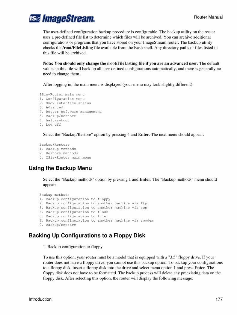
The user-defined configuration backup procedure is configurable. The backup utility on the routeruses a pre-defined file list to determine which files will be archived. You can archive additionalconfigurations or programs that you have stored on your ImageStream router. The backup utilitychecks the /root/FileListing file available from the Bash shell. Any directory paths or files listed inthis file will be archived.
Note: You should only change the /root/FileListing file if you are an advanced user. The defaultvalues in this file will back up all user-defined configurations automatically, and there is generally noneed to change them.
After logging in, the main menu is displayed (your menu may look slightly different):
ISis-Router main menu 1. Configuration menu 2. Show interface status 3. Advanced 4. Router software management 5. Backup/Restore 6. halt/reboot 0. Log off
Select the "Backup/Restore" option by pressing 4 and Enter. The next menu should appear:
Backup/Restore 1. Backup methods 2. Restore methods 0. ISis-Router main menu
Using the Backup Menu
Select the "Backup methods" option by pressing 1 and Enter. The "Backup methods" menu shouldappear:
Backup methods 1. Backup configuration to floppy 2. Backup configuration to another machine via ftp 3. Backup configuration to another machine via scp 4. Backup configuration to flash 5. Backup configuration to file 6. Backup configuration to another machine via zmodem 0. Backup/Restore
Backing Up Configurations to a Floppy Disk
1. Backup configuration to floppy
To use this option, your router must be a model that is equipped with a "3.5" floppy drive. If yourrouter does not have a floppy drive, you cannot use this backup option. To backup your configurationsto a floppy disk, insert a floppy disk into the drive and select menu option 1 and press Enter. Thefloppy disk does not have to be formatted. The backup process will delete any preexisting data on thefloppy disk. After selecting this option, the router will display the following message:
Router Manual
Introduction 177
Insert a floppy diskette then hit <Enter>.
Press Enter once you have inserted the floppy disk. The router will then format the floppy disk andbackup the running configuration from memory to the floppy disk:
Formatting floppy diskette...done Configuration saved to floppy
The messages will only be displayed for a few seconds, and then you will be returned to the Backupmethods menu.
Backing Up Configurations to a Remote Machine using FTP
2. Backup configuration to another machine via ftp
The router configurations can be backed up on a remote machine using the FTP service. To backupyour configurations, select menu option 2 and press Enter. To use this option, you must have accessto a remote machine with a functioning FTP server and user account. After selecting this option, therouter will display the message:
Enter destination to backup to "<user>@<hostname>:<directory>" :
Enter the login name, hostname or IP address, and path where the configuration archive should bestored at this prompt. For example, if the remote FTP server is located at the IP address192.168.100.10, your user account is support, and you want to store the configuration archive in the/tmp directory, you would enter:
[email protected]:/tmp
at the prompt. Press Enter once you have entered the remote server's login and path information.Once the router has connected to the remote FTP server, you will be prompted for a password.
The router will then copy a file named ISisConfig.tar.gz to the specified location on the FTP server.This file has been archived and compressed using the tar and gzip utilities, respectively. When the filehas been copied successfully, a status message will be displayed for a few seconds (your message willlook slightly different):
/tmp/ISisConfig.tar.gz: 114.28 kB 2.75 MB/s
you will then be returned to the Backup methods menu.
Backing Up Configurations to a Remote Machine using SCP
3. Backup configuration to another machine via scp
The router configurations can be backed up on a remote machine using the scp (secure copy) service.To use this option, you must have access to a remote machine with a functioning SSH server and useraccount. To backup your configurations, select menu option 3 and press Enter. After selecting thisoption, the router will display the message:
Router Manual
178 Backing Up Configurations to a Floppy Disk
Enter destination to backup to "<user>@<hostname>:<directory>" :
Enter the login name, hostname or IP address, and path where the configuration archive should bestored at this prompt. For example, if the remote FTP server is located at the IP address192.168.100.10, your user account is support, and you want to store the configuration archive in the/tmp directory, you would enter:
[email protected]:/tmp
at the prompt. Press Enter once you have entered the remote server's login and path information. Therouter will temporarily save the configuration archive in the /tmp directory and then attempt to copy itto the remote server you specified. Once the router has connected to the remote machine, you will beprompted for a password.
The router will then copy a file named ISisConfig.tar.gz to the specified location on the remotemachine. This file has been archived and compressed using the tar and gzip utilities, respectively.When the file has been copied successfully, a status message will be displayed for a few seconds(your message will look slightly different):
ISisConfig.tar.gz 100% |*** ***| 114 KB 00:00 Configuration saved to [email protected]:/tmp/ISisConfig.tar.gz
you will then be returned to the Backup methods menu.
Backing Up Configurations to the Flash Device
4. Backup configuration to flash
To backup your configurations to the router's built-in flash storage device, select menu option 4 andpress "Enter". The router will then backup the running configuration from memory to the flash deviceand display the following message:
Configuration saved to flash
The message will only be displayed for a few seconds, and then you will be returned to the Backupmethods menu.
Backing Up Configurations to a File
5. Backup configuration to file
To backup your configurations to a file stored temporarily in the running memory, select menu option5 and press Enter. Selecting this option will allow you to save your configurations to a file, which canbe used to quickly restore a configuration or to copy to a remote machine. After selecting this option,the router will display the following message:
Enter filename to backup configuration to :
Router Manual
Backing Up Configurations to a Remote Machine using SCP 179
Enter the path to the location where you want to store the configuration archive. For example, it youwant to store the configuration tar archive in the /tmp directory in a file called ISisConfig.tar.gz, youwould enter:
/tmp/ISisConfig.tar.gz
at the prompt. Remember that the configuration archive created by the router is a gzipped tar archive,regardless of any file extensions you choose. By convention, ImageStream recommends using the.tar.gz extension on any configuration archive. Press Enter once you have entered the pathinformation.
The router will then backup the running configuration from memory to the flash device and displaythe following message (your message may differ):
Settings saved to /tmp/ISisConfig.tar.gz
The message will only be displayed for a few seconds, and then you will be returned to the Backupmethods menu.
Backing Up Configurations through a Terminal Program using ZMODEM
6. Backup configuration to another machine via zmodem
The router configurations can be backed up on a remote machine using the ZMODEM, XMODEM orYMODEM services. To use this option, your terminal program must support at least one ofZMODEM, XMODEM or YMODEM transfer services. Common programs such as minicom orHyperTerminal support ZMODEM transfers. Many popular SSH and telnet clients support ZMODEMtransfers also. Refer to the documentation of your terminal program to determine if it supports thistransfer function.
ImageStream recommends using the ZMODEM protocol whenever possible, since this protocol willtransfer files the quickest. To backup your configurations, select menu option 6 and press Enter.After selecting this option, the router will display the following message:
Enter filename to create and send to remote system :
Enter the filename that you want to use for the configuration. Remember that the configurationarchive created by the router is a gzipped tar archive, regardless of any file extensions you choose. Byconvention, ImageStream recommends using the .tar.gz extension on any configuration archive. Forexample, if you want to store the file router.tar.gz, you would enter:
router.tar.gz
at the prompt. Press Enter once you have entered the filename information. The router willtemporarily save the configuration archive in the /tmp directory and then will display the message:
Use X, Y or ZMODEM protocol (Default: ZMODEM)? (x/y/Z)
Router Manual
180 Backing Up Configurations to a File
Select the file transfer protocol that you want to use and that is supported by your terminal program. Ifyou are unsure, select the default, ZMODEM, by pressing Z and Enter. The router will pause to allowyou to set up your terminal program, if necessary (in most cases, terminal programs require noadvance setup to receive files using ZMODEM). When you are ready to copy the file to the remotemachine, press Enter.
The router will then copy a file using the name you specified in the first step to your local machine.Your terminal program may prompt you for a location to save this file, or the program may save thefile automatically. Please refer to the documentation of your terminal program to determine where thebackup archive will be stored. When the file has been copied successfully, you will be returned to theBackup methods menu.
Returning to the Backup/Restore Menu
0. Backup/Restore
Selecting this menu option returns you to the "Backup/Restore" menu. To return to theBackup/Restore menu, press 0 and Enter. The router will display the Backup/Restore menu:
Backup/Restore 1. Backup methods 2. Restore methods 0. ISis-Router main menu
Using the Restore Menu
Select the "Restore methods" option by pressing 2 and Enter. ImageStream router configurations areportable between router models. You can restore configurations from any ImageStream router ontoany other ImageStream router. After selecting the "Restore methods" option, the "Restore methods"menu should appear:
Restore methods 1. Restore configuration from floppy 2. Restore configuration from another machine via ftp 3. Restore configuration from another machine via scp 4. Restore configuration from flash 5. Restore configuration from file 6. Restore configuration from another machine via zmodem 7. Restore router to factory defaults 0. Backup/Restore
Restoring Configurations from a Floppy Disk
1. Restore configuration from floppy
To use this option, your router must be a model that is equipped with a "3.5" floppy drive. If yourrouter does not have a floppy drive, you cannot use this restore option. To restore your configurationsfrom a floppy disk, insert a floppy disk with a configuration saved from an ImageStream router intothe drive and select menu option 1 and press Enter. The floppy disk must be one created by a backupfloppy command (or menu option) on an ImageStream router. If a floppy disk without a valid
Router Manual
Backing Up Configurations through a Terminal Program using ZMODEM 181
configuration archive is inserted, the router will display the following message:
Error: Not a backup configuration. Please insert proper floppy.
Once you have inserted a valid floppy disk, the router will copy the configuration from the floppydisk to the running configuration in memory and display the following message:
Configuration restored from floppy
The message will be displayed for a few seconds, and you will be returned to the Restore methodsmenu. You must backup your configurations to flash after using this method. The restoration processonly affects the running configuration not the one stored in the router's nonvolatile flash device.
Restoring Configurations from a Remote Machine using FTP
2. Restore configuration from another machine via ftp
The router configurations can be restored from an archive stored on a remote machine by using theFTP service. To restore your configurations via FTP, select menu option 2 and press Enter. To usethis option, you must have access to a stored configuration on a remote machine with a functioningFTP server and user account. After selecting this option, the router will display the followingmessage:
Enter where to restore backup from "<user>@<hostname>:<directory>" :
Enter the login name, hostname or IP address, and path where the configuration archive namedISisConfig.tar.gz is located at this prompt. For example, if the remote FTP server is located at the IPaddress 192.168.100.10, your user account is support, and you want to restore the configurationarchive from the /tmp directory, you would enter:
[email protected]:/tmp
at the prompt. Press Enter once you have entered the remote server's login and path information.Once the router has connected to the remote FTP server, you will be prompted for a password. Whenthe file has been copied successfully, the router will copy the configuration from the configurationarchive to the running configuration in memory. The router will display a status message (yourmessage will look slightly different):
/tmp/ISisConfig.tar.gz: 114.28 kB 2.75 MB/s
The message will be displayed for only a few seconds, and then you will be returned to the "Restoremethods" menu. You must backup your configurations to flash after using this method. Therestoration process only affects the running configuration, and not the one stored in the router'snonvolatile flash device.
Router Manual
182 Using the Restore Menu
Restoring Configurations from a Remote Machine using SCP
3. Restore configuration from another machine via scp
The router configurations can be restored from an archive stored on a remote machine by using thescp (secure copy) service. To restore your configurations via scp, select menu option 3 and pressEnter. To use this option, you must have access to a stored configuration on a remote machine with afunctioning SSH server and user account. After selecting this option, the router will display thefollowing message:
Enter where to restore backup from "<user>@<hostname>:<directory>" :
enter the login name, hostname or IP address, and path where the configuration archive namedISisConfig.tar.gz is located at this prompt. For example, if the remote server is located at the IPaddress 192.168.100.10, your user account is support, and you want to restore the configurationarchive from the /tmp directory, you would enter:
[email protected]:/tmp
at the prompt. Press Enter once you have entered the remote server's login and path information.Once the router has connected to the remote server, you will be prompted for a password. When thefile has been copied successfully, the router will copy the configuration from the configurationarchive to the running configuration in memory. The router will display a status message (yourmessage will look slightly different):
ISisConfig.tar.gz 100% |*** ***| 114 KB 00:00 Configuration restored from [email protected]:/tmp
The message will be displayed for only a few seconds, and then you will be returned to the "Restoremethods" menu. You must backup your configurations to flash after using this method. Therestoration process only affects the running configuration, and not the one stored in the router'snonvolatile flash device.
Restore Configurations from the Flash Device
4. Restore configuration from flash
To restore your configurations from the router's built-in flash storage device, select menu option 4 andpress Enter. The router will then copy the stored configuration from the flash device to the runningconfiguration in memory and then display the following message:
Configuration restored from flash
The message will only be displayed for a few seconds, and then you will be returned to the Restoremethods menu.
Router Manual
Using the Restore Menu 183
Restore Configurations from a File
5. Restore configuration from a file
To restore your configurations from a file stored temporarily in the running memory, select menuoption 5 and press Enter. Selecting this option will allow you to restore your configurations from afile. After selecting this option, the router will display the following message:
Enter filename to restore configuration from :
enter the path to the location where you want to store the configuration archive. For example, it youwant to store the configuration tar archive in the /tmp directory in a file called ISisConfig.tar.gz, youwould enter:
/tmp/ISisConfig.tar.gz
at the prompt. Remember that the configuration archive created by the router is a gzipped tar archive,regardless of any file extensions you choose. By convention, ImageStream recommends using the.tar.gz extension on any configuration archive. Press Enter once you have entered the pathinformation. The router will then restore the running configuration using the configuration archiveyou specified and display the message (your message may differ):
Settings restored from /tmp/ISisConfig.tar.gz
The message will only be displayed for a few seconds, and then you will be returned to the Restoremethods menu.
Backing Up Configurations through a Terminal Program using ZMODEM
6. Restore configuration from another machine via zmodem
The router configurations can be restored from a remote machine using the ZMODEM, XMODEM orYMODEM services. To use this option, your terminal program must support at least one ofZMODEM, XMODEM or YMODEM transfer services. Common programs such as minicom orHyperTerminal support ZMODEM transfers. Many popular SSH and telnet clients support ZMODEMtransfers also. Refer to the documentation of your terminal program to determine if it supports thistransfer function.
ImageStream recommends using the ZMODEM protocol whenever possible, since this protocol willtransfer files the quickest. To restore your configurations, select this menu option 6 and press Enter.After selecting this option, the router will display the following message:
Use X, Y or ZMODEM protocol (Default: ZMODEM)? (x/y/Z)
Select the file transfer protocol that you want to use and that is supported by your terminal program. Ifyou are unsure, select the default, ZMODEM, by pressing Z and Enter. The router will pause to allowyou to set up your terminal program, if necessary (in most cases, terminal programs require noadvance setup to receive files using ZMODEM). When you are ready to copy the file from the remotemachine, press Enter.
Router Manual
184 Using the Restore Menu
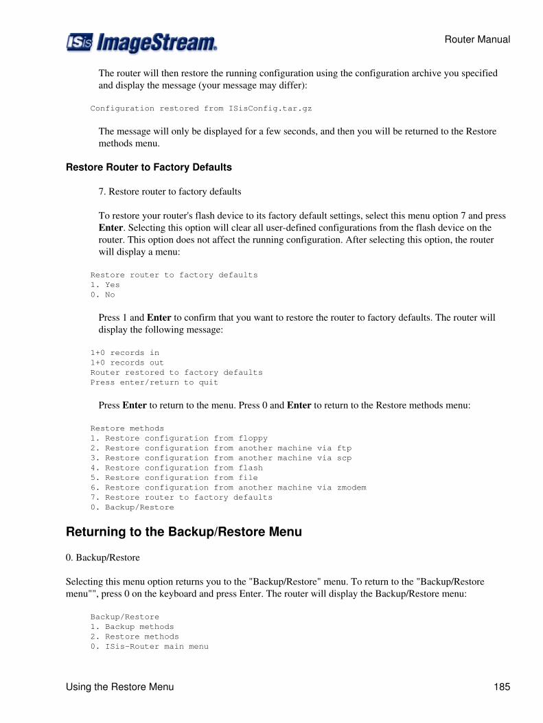
The router will then restore the running configuration using the configuration archive you specifiedand display the message (your message may differ):
Configuration restored from ISisConfig.tar.gz
The message will only be displayed for a few seconds, and then you will be returned to the Restoremethods menu.
Restore Router to Factory Defaults
7. Restore router to factory defaults
To restore your router's flash device to its factory default settings, select this menu option 7 and pressEnter. Selecting this option will clear all user-defined configurations from the flash device on therouter. This option does not affect the running configuration. After selecting this option, the routerwill display a menu:
Restore router to factory defaults 1. Yes 0. No
Press 1 and Enter to confirm that you want to restore the router to factory defaults. The router willdisplay the following message:
1+0 records in 1+0 records out Router restored to factory defaults Press enter/return to quit
Press Enter to return to the menu. Press 0 and Enter to return to the Restore methods menu:
Restore methods 1. Restore configuration from floppy 2. Restore configuration from another machine via ftp 3. Restore configuration from another machine via scp 4. Restore configuration from flash 5. Restore configuration from file 6. Restore configuration from another machine via zmodem 7. Restore router to factory defaults 0. Backup/Restore
Returning to the Backup/Restore Menu
0. Backup/Restore
Selecting this menu option returns you to the "Backup/Restore" menu. To return to the "Backup/Restoremenu"", press 0 on the keyboard and press Enter. The router will display the Backup/Restore menu:
Backup/Restore 1. Backup methods 2. Restore methods 0. ISis-Router main menu
Router Manual
Using the Restore Menu 185

Using the Interface Statistics (STATS) Program
This chapter describes how to use the real-time interface statistics program (stats) on the ImageStreamrouter. The stats program allows you to access detailed information about the LAN, WAN and virtualinterfaces on an ImageStream router in an easy-to-use, real-time layout.
This chapter describes the basic operation of the stats program, including the summary, detail, andCSU/DSU screen and sorting options and includes the following topics:
Understanding the summary screen◊ Understanding the detail screen◊ Understanding the CSU/DSU detail screen◊ Viewing traffic◊
After logging in, the main menu is displayed (your menu may look slightly different):
ISis-Router main menu 1. Configuration menu 2. Show interface status 3. Advanced 4. Router software management 5. Backup/Restore 6. halt/reboot 0. Log off
Select menu option 2, Show interface status, and press Enter. This will display a screen with one-linesummaries of each interface and subinterface in your system.
Understanding the Summary Screen
2. Show interface status
To display "Show interface status" select menu option 2 and press Enter. The router displaying thesummary statistics screen (your exact display will differ):
17:27:21 Interface Summary router# Port Description Encaps Bandwidth HW Proto In Out 0 Ethernet0 100Mb Ethernet 100baseTx-FD 100.00 Mbit up up 3% 2% 1 Serial0 ISis PCI 604-T1 Port 0 down shut 2 Serial1 ISis PCI 604-T1 Port 1 down shut 3 Serial2 Qwest T1 Cisco HDLC 1.54 Mbit up up 18% 41% 4 Serial3 Qwest T1 Cisco HDLC 1.54 Mbit up up 20% 41% 5 Serial4 ISis PCI 522-T1 Port Frame Relay 1.54 Mbit up up 63% 19% 6 Serial 4.1 Sprint T1 1.54 Mbit up up 63% 19% 7 Serial5 ISis PCI 522-T1 Port Frame Relay 1.54 Mbit up down 00:00:12 8 Serial5.1 Office to TNT 1.54 Mbit up down 00:00:12 9 Bonder0 Qwest T1s none 3.07 Mbit up up 19% 41% d Detail | s Sleep interval | n Next | p Previous | h Help | q Quit
Router Manual
186 Using the Interface Statistics (STATS) Program
Each line of the output is described below, beginning with the first line:
17:27:21 - The current system time. This time stamp is updated according to the Sleep interval. Thedefault interval is 3 seconds.
Interface Summary - A label indicating that you are viewing the summary screen.
router - The hostname configured on the router.
Line two contains the column labels explaining the statistics output.
# - Indicates the line number in the summary output. When selecting the detail option, you will beprompted for this line number.
Port - This column shows the name of the corresponding device configured in the interfaceconfiguration file (wan.conf) file.
Description - This column shows the value configured by the description keyword (if any) in theinterface configuration file (wan.conf) file. A default description is displayed if one has not beenmanually configured.
Encapsulation - Displays the configured encapsulation for the device. Ethernet devices will show theconfigured or negotiated link speed, according to the Ethernet port's MII registers. Devices that havenot been configured or that are administratively shut down will not display a value. Bonder and otherspecial devices will not display a value.
Bandwidth - Indicates the bandwidth value or channel group configured in the interfaceconfiguration file (wan.conf) or learned from the integrated CSU/DSU on the port. Devices that havenot been configured or that are administratively shut down will not display a value. Bonder deviceswill display the combined bandwidth of all active bonded devices.
HW - Indicates whether or not the interface hardware connection to the telephone company networkor external CSU/DSU is active. If a carrier signal is detected on the line, this column will display up.If carrier is not detected on the line, or if the interface has not been configured or administrativelyshut down, the column will display down.
Proto - Indicates whether the software processes that handle the device's protocol consider the lineusable (that is, whether keepalives are successful) or if it has been taken down by an administrator. Ifa usable connection has been established, this column will display up. If a connection has not beenestablished, the column will display down. If the device is administratively shut down, the columnwill display shut. Pro6tocols, such as rawip or frame-relay ietf with LMI disabled, will always displayup if the hardware connection is up.
In/Out - Displays the amount of traffic currently on the interface. The percentage displayed iscalculated using the sleep interval and bandwidth value on the interface. If the device has not been upsince the router was booted or the SAND service started, the columns will display never up. If thedevice is administratively shut down, the columns will not display any values. If the hardware orprotocol is down on the device, the length of time since the device's status changed to down will be
Router Manual
Understanding the Summary Screen 187
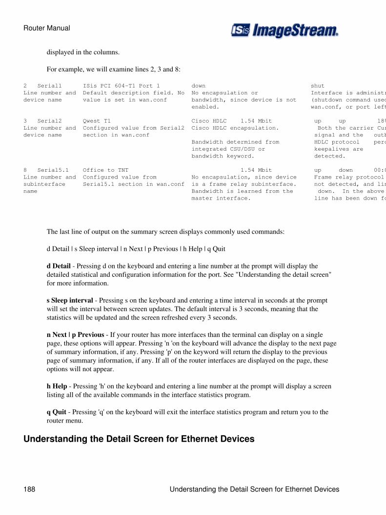
displayed in the columns.
For example, we will examine lines 2, 3 and 8:
2 Serial1 ISis PCI 604-T1 Port 1 down shutLine number and Default description field. No No encapsulation or Interface is administratively down device name value is set in wan.conf bandwidth, since device is not (shutdown command used in enabled. wan.conf, or port left unconfigured).
3 Serial2 Qwest T1 Cisco HDLC 1.54 Mbit up up 18% 41% Line number and Configured value from Serial2 Cisco HDLC encapsulation. Both the carrier Current inbound anddevice name section in wan.conf signal and the outbound traffic Bandwidth determined from HDLC protocol percentages integrated CSU/DSU or keepalives are bandwidth keyword. detected.
8 Serial5.1 Office to TNT 1.54 Mbit up down 00:00:12Line number and Configured value from No encapsulation, since device Frame relay protocol keepalives aresubinterface Serial5.1 section in wan.conf is a frame relay subinterface. not detected, and line protocol isname Bandwidth is learned from the down. In the above example, the master interface. line has been down for 12 seconds.
The last line of output on the summary screen displays commonly used commands:
d Detail | s Sleep interval | n Next | p Previous | h Help | q Quit
d Detail - Pressing d on the keyboard and entering a line number at the prompt will display thedetailed statistical and configuration information for the port. See "Understanding the detail screen"for more information.
s Sleep interval - Pressing s on the keyboard and entering a time interval in seconds at the promptwill set the interval between screen updates. The default interval is 3 seconds, meaning that thestatistics will be updated and the screen refreshed every 3 seconds.
n Next | p Previous - If your router has more interfaces than the terminal can display on a singlepage, these options will appear. Pressing 'n 'on the keyboard will advance the display to the next pageof summary information, if any. Pressing 'p' on the keyword will return the display to the previouspage of summary information, if any. If all of the router interfaces are displayed on the page, theseoptions will not appear.
h Help - Pressing 'h' on the keyboard and entering a line number at the prompt will display a screenlisting all of the available commands in the interface statistics program.
q Quit - Pressing 'q' on the keyboard will exit the interface statistics program and return you to therouter menu.
Understanding the Detail Screen for Ethernet Devices
Router Manual
188 Understanding the Detail Screen for Ethernet Devices
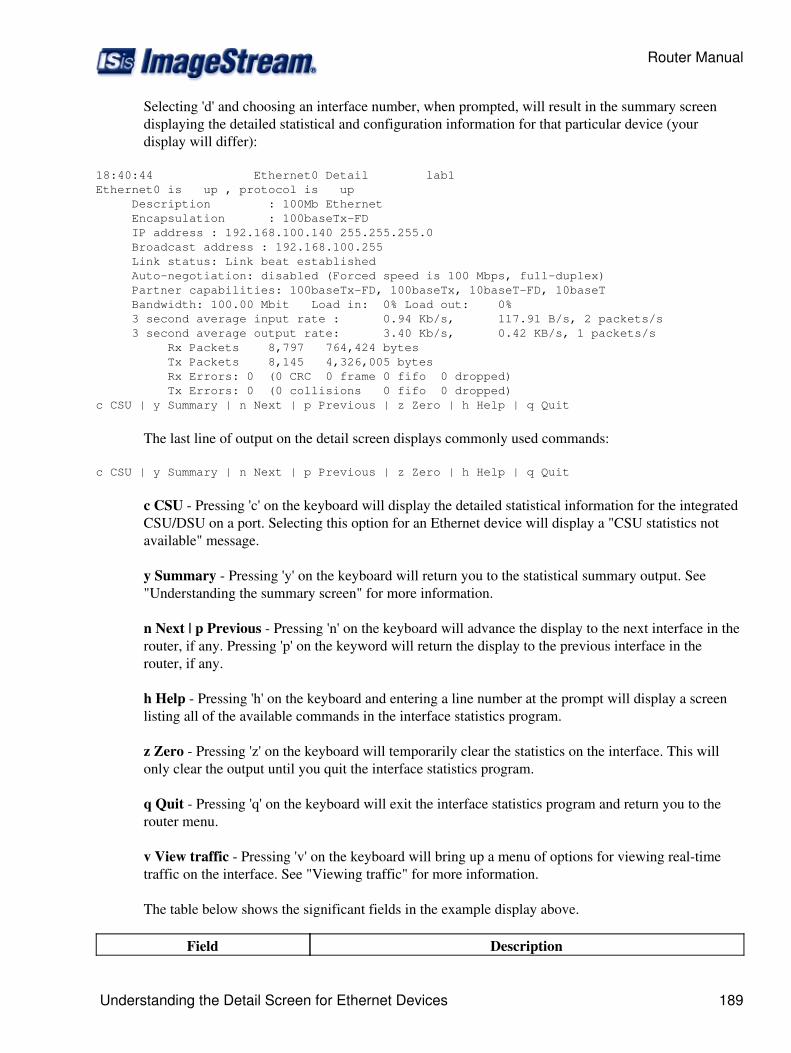
Selecting 'd' and choosing an interface number, when prompted, will result in the summary screendisplaying the detailed statistical and configuration information for that particular device (yourdisplay will differ):
18:40:44 Ethernet0 Detail lab1Ethernet0 is up , protocol is up Description : 100Mb Ethernet Encapsulation : 100baseTx-FD IP address : 192.168.100.140 255.255.255.0 Broadcast address : 192.168.100.255 Link status: Link beat established Auto-negotiation: disabled (Forced speed is 100 Mbps, full-duplex) Partner capabilities: 100baseTx-FD, 100baseTx, 10baseT-FD, 10baseT Bandwidth: 100.00 Mbit Load in: 0% Load out: 0% 3 second average input rate : 0.94 Kb/s, 117.91 B/s, 2 packets/s 3 second average output rate: 3.40 Kb/s, 0.42 KB/s, 1 packets/s Rx Packets 8,797 764,424 bytes Tx Packets 8,145 4,326,005 bytes Rx Errors: 0 (0 CRC 0 frame 0 fifo 0 dropped) Tx Errors: 0 (0 collisions 0 fifo 0 dropped)c CSU | y Summary | n Next | p Previous | z Zero | h Help | q Quit
The last line of output on the detail screen displays commonly used commands:
c CSU | y Summary | n Next | p Previous | z Zero | h Help | q Quit
c CSU - Pressing 'c' on the keyboard will display the detailed statistical information for the integratedCSU/DSU on a port. Selecting this option for an Ethernet device will display a "CSU statistics notavailable" message.
y Summary - Pressing 'y' on the keyboard will return you to the statistical summary output. See"Understanding the summary screen" for more information.
n Next | p Previous - Pressing 'n' on the keyboard will advance the display to the next interface in therouter, if any. Pressing 'p' on the keyword will return the display to the previous interface in therouter, if any.
h Help - Pressing 'h' on the keyboard and entering a line number at the prompt will display a screenlisting all of the available commands in the interface statistics program.
z Zero - Pressing 'z' on the keyboard will temporarily clear the statistics on the interface. This willonly clear the output until you quit the interface statistics program.
q Quit - Pressing 'q' on the keyboard will exit the interface statistics program and return you to therouter menu.
v View traffic - Pressing 'v' on the keyboard will bring up a menu of options for viewing real-timetraffic on the interface. See "Viewing traffic" for more information.
The table below shows the significant fields in the example display above.
Field Description
Router Manual
Understanding the Detail Screen for Ethernet Devices 189

Ethernet is {up | down} Indicates whether the interface hardware is currently active (whether alink beat is present).
protocol is {up | down |administratively down}
Indicates whether the Ethernet device's MII registers consider the lineusable (that is, whether a link has been established).
Description Displays the value of the description parameter specified in the interfaceconfiguration file (wan.conf) or a default description for the port.
Encapsulation Displays the link speed and duplex configuration negotiated or set in theEthernet device's MII registers.
IP address Indicates the Internet address and subnet mask configured on theinterface in the interface configuration file (wan.conf).
Broadcast address Specifies the broadcast address determined by the IP address/netmaskcombination configured on the interface.
Link status Displays the MII link status of the Ethernet interfaces. This status shouldcorrespond to the link status indication on the connected device.
Auto-negotiationDisplays enabled and the negotiated value when MII negotiation isenabled on the port. Displays disabled and the forced configurationspeed when MII negotiation is disabled on the port.
Partner capabilities Displays the MII-advertised capabilities of the connected devices.
Bandwidth
Indicates the value of the bandwidth parameter that has been determinedautomatically by autonegotiation or a forced configuration.
Load in Indicates the inbound load on the interface as a fraction of thebandwidth, calculated as an average over the current sleep interval.
Load out Indicates the outbound load on the interface as a fraction of thebandwidth, calculated as an average over the current sleep interval
__ second average input rate Indicates the actual inbound data rate load on the interface, calculated asan average over the specified sleep interval
__ second average output rate Indicates the actual outbound data rate load on the interface, calculatedas an average over the specified sleep interval
Rx/Tx PacketsDisplays the total number of error-free packets received/sent by thesystem and total number of bytes, including data and MACencapsulation in the error-free packets received/sent by the system.
Rx/Tx Errors Displays the total number of no buffer(fifo), CRC, frame, overrun,ignored, and abort error counts recorded on the interface.
CRC
Indicates the number of cyclic redundancy checksum errors generated bythe originating station or far-end device that did not match the checksumcalculated from the data received. On a serial link, CRC's usuallyindicate noise, gain hits, or other transmission problems.
FrameIndicates the number of packets received with a CRC error and anon-integer number of octets. On a serial line, this is usually the result ofnoise or other transmission problems.
Fifo Indicates the number of received packets discarded because there was nobuffer space in the main system.
dropped Indicates the number of received packets ignored by the interface
Router Manual
190 Understanding the Detail Screen for Ethernet Devices
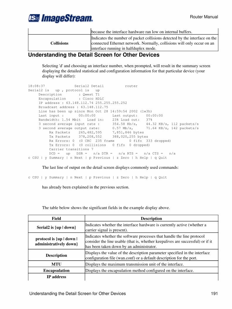
because the interface hardware ran low on internal buffers.
CollisionsIndicates the number of packet collisions detected by the interface on theconnected Ethernet network. Normally, collisions will only occur on aninterface running in halfduplex mode.
Understanding the Detail Screen for Other Devices
Selecting 'd' and choosing an interface number, when prompted, will result in the summary screendisplaying the detailed statistical and configuration information for that particular device (yourdisplay will differ):
18:08:37 Serial2 Detail routerSerial2 is up , protocol is up Description : Qwest T1 Encapsulation : Cisco HDLC IP address : 63.148.112.74 255.255.255.252 Broadcast address : 63.148.112.75 Line has been up since Mon Oct 28 14:59:54 2002 (1w3h) Last input : 00:00:00 Last output: 00:00:00 Bandwidth: 1.54 Mbit Load in: 23% Load out: 37% 3 second average input rate : 354.58 Kb/s, 44.32 KB/s, 112 packets/s 3 second average output rate: 0.57 Mb/s, 71.64 KB/s, 142 packets/s Rx Packets 265,482,595 7,851,846 bytes Tx Packets 378,208,552 388,020,255 bytes Rx Errors: 0 (0 CRC 235 frame 0 fifo 333 dropped) Tx Errors: 0 (0 collisions 0 fifo 0 dropped) Carrier transitions 7 DCD = up DSR = n/a DTR = n/a RTS = n/a CTS = n/a c CSU | y Summary | n Next | p Previous | z Zero | h Help | q Quit
The last line of output on the detail screen displays commonly used commands:
c CSU | y Summary | n Next | p Previous | z Zero | h Help | q Quit
has already been explained in the previous section.
The table below shows the significant fields in the example display above.
Field Description
Serial2 is {up | down} Indicates whether the interface hardware is currently active (whether acarrier signal is present).
protocol is {up | down |administratively down}
Indicates whether the software processes that handle the line protocolconsider the line usable (that is, whether keepalives are successful) or if ithas been taken down by an administrator.
Description Displays the value of the description parameter specified in the interfaceconfiguration file (wan.conf) or a default description for the port.
MTU Displays the maximum transmission unit of the interface.Encapsulation Displays the encapsulation method configured on the interface.
IP address
Router Manual
Understanding the Detail Screen for Other Devices 191
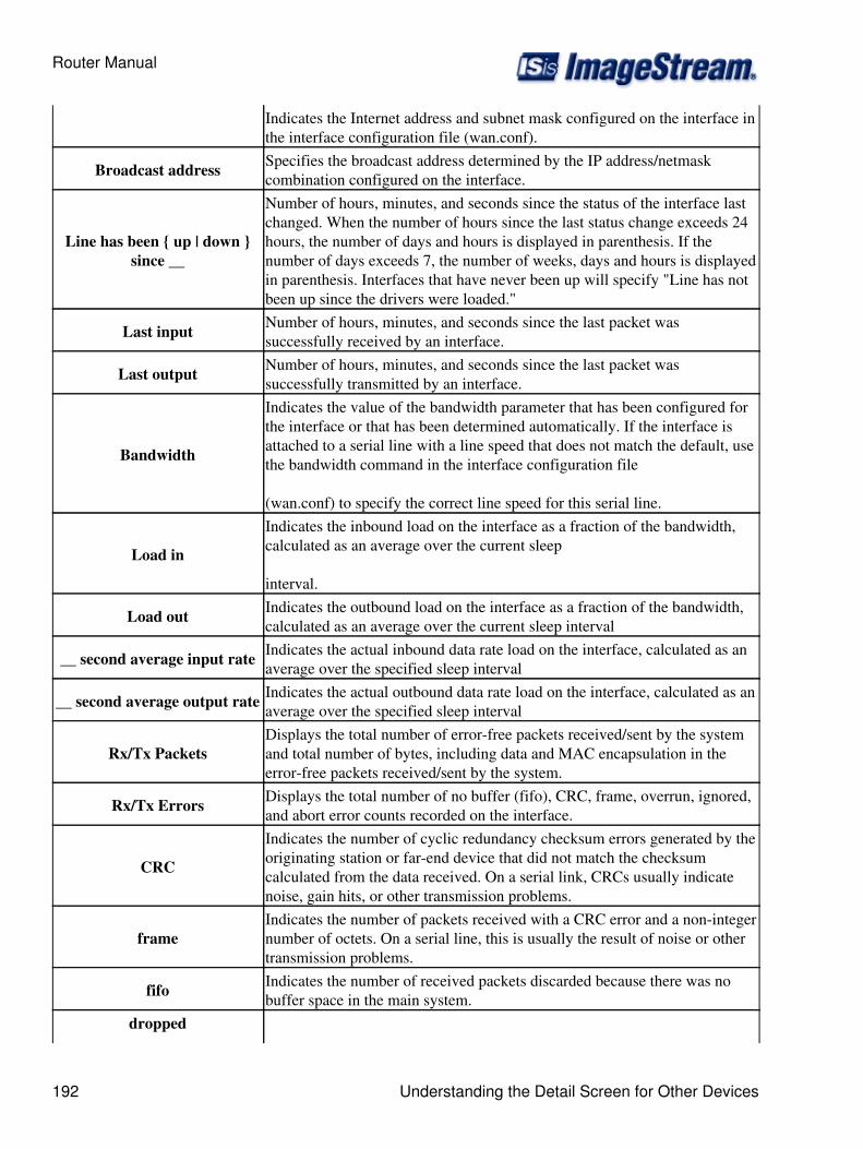
Indicates the Internet address and subnet mask configured on the interface inthe interface configuration file (wan.conf).
Broadcast address Specifies the broadcast address determined by the IP address/netmaskcombination configured on the interface.
Line has been { up | down }since __
Number of hours, minutes, and seconds since the status of the interface lastchanged. When the number of hours since the last status change exceeds 24hours, the number of days and hours is displayed in parenthesis. If thenumber of days exceeds 7, the number of weeks, days and hours is displayedin parenthesis. Interfaces that have never been up will specify "Line has notbeen up since the drivers were loaded."
Last input Number of hours, minutes, and seconds since the last packet wassuccessfully received by an interface.
Last output Number of hours, minutes, and seconds since the last packet wassuccessfully transmitted by an interface.
Bandwidth
Indicates the value of the bandwidth parameter that has been configured forthe interface or that has been determined automatically. If the interface isattached to a serial line with a line speed that does not match the default, usethe bandwidth command in the interface configuration file
(wan.conf) to specify the correct line speed for this serial line.
Load in
Indicates the inbound load on the interface as a fraction of the bandwidth,calculated as an average over the current sleep
interval.
Load out Indicates the outbound load on the interface as a fraction of the bandwidth,calculated as an average over the current sleep interval
__ second average input rate Indicates the actual inbound data rate load on the interface, calculated as anaverage over the specified sleep interval
__ second average output rate Indicates the actual outbound data rate load on the interface, calculated as anaverage over the specified sleep interval
Rx/Tx PacketsDisplays the total number of error-free packets received/sent by the systemand total number of bytes, including data and MAC encapsulation in theerror-free packets received/sent by the system.
Rx/Tx Errors Displays the total number of no buffer (fifo), CRC, frame, overrun, ignored,and abort error counts recorded on the interface.
CRC
Indicates the number of cyclic redundancy checksum errors generated by theoriginating station or far-end device that did not match the checksumcalculated from the data received. On a serial link, CRCs usually indicatenoise, gain hits, or other transmission problems.
frameIndicates the number of packets received with a CRC error and a non-integernumber of octets. On a serial line, this is usually the result of noise or othertransmission problems.
fifo Indicates the number of received packets discarded because there was nobuffer space in the main system.
dropped
Router Manual
192 Understanding the Detail Screen for Other Devices
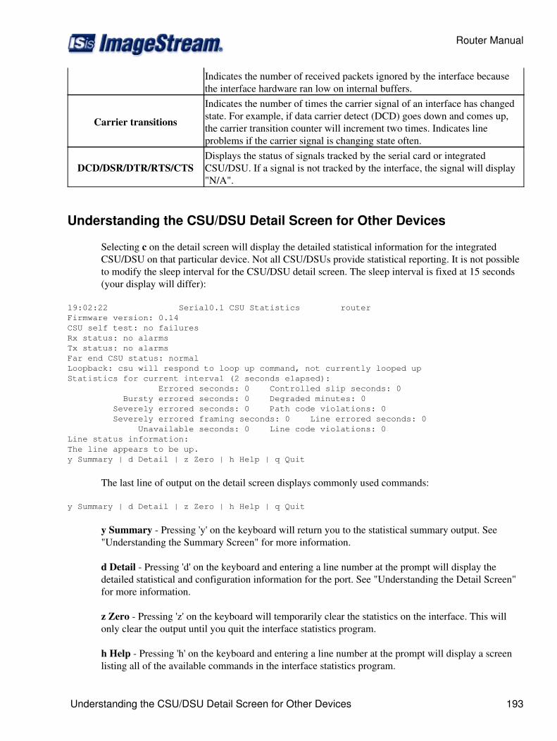
Indicates the number of received packets ignored by the interface becausethe interface hardware ran low on internal buffers.
Carrier transitions
Indicates the number of times the carrier signal of an interface has changedstate. For example, if data carrier detect (DCD) goes down and comes up,the carrier transition counter will increment two times. Indicates lineproblems if the carrier signal is changing state often.
DCD/DSR/DTR/RTS/CTSDisplays the status of signals tracked by the serial card or integratedCSU/DSU. If a signal is not tracked by the interface, the signal will display"N/A".
Understanding the CSU/DSU Detail Screen for Other Devices
Selecting c on the detail screen will display the detailed statistical information for the integratedCSU/DSU on that particular device. Not all CSU/DSUs provide statistical reporting. It is not possibleto modify the sleep interval for the CSU/DSU detail screen. The sleep interval is fixed at 15 seconds(your display will differ):
19:02:22 Serial0.1 CSU Statistics routerFirmware version: 0.14 CSU self test: no failures Rx status: no alarms Tx status: no alarms Far end CSU status: normal Loopback: csu will respond to loop up command, not currently looped up Statistics for current interval (2 seconds elapsed): Errored seconds: 0 Controlled slip seconds: 0 Bursty errored seconds: 0 Degraded minutes: 0 Severely errored seconds: 0 Path code violations: 0 Severely errored framing seconds: 0 Line errored seconds: 0 Unavailable seconds: 0 Line code violations: 0Line status information: The line appears to be up. y Summary | d Detail | z Zero | h Help | q Quit
The last line of output on the detail screen displays commonly used commands:
y Summary | d Detail | z Zero | h Help | q Quit
y Summary - Pressing 'y' on the keyboard will return you to the statistical summary output. See"Understanding the Summary Screen" for more information.
d Detail - Pressing 'd' on the keyboard and entering a line number at the prompt will display thedetailed statistical and configuration information for the port. See "Understanding the Detail Screen"for more information.
z Zero - Pressing 'z' on the keyboard will temporarily clear the statistics on the interface. This willonly clear the output until you quit the interface statistics program.
h Help - Pressing 'h' on the keyboard and entering a line number at the prompt will display a screenlisting all of the available commands in the interface statistics program.
Router Manual
Understanding the CSU/DSU Detail Screen for Other Devices 193
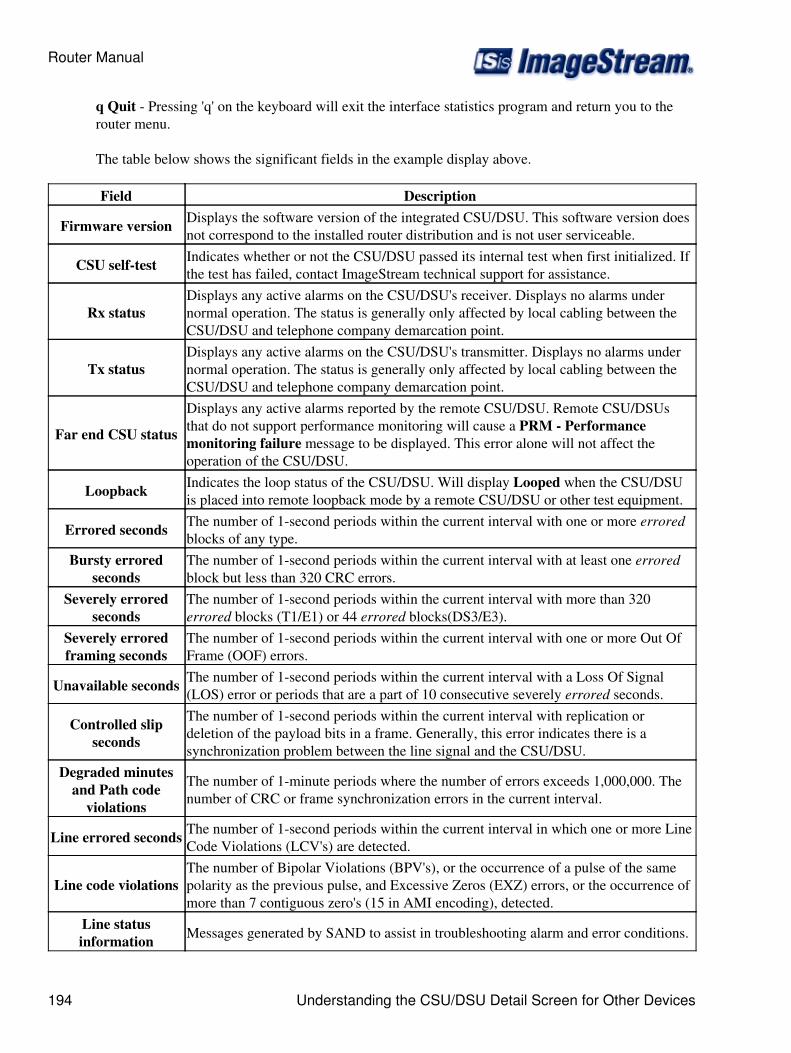
q Quit - Pressing 'q' on the keyboard will exit the interface statistics program and return you to therouter menu.
The table below shows the significant fields in the example display above.
Field Description
Firmware version Displays the software version of the integrated CSU/DSU. This software version doesnot correspond to the installed router distribution and is not user serviceable.
CSU self-test Indicates whether or not the CSU/DSU passed its internal test when first initialized. Ifthe test has failed, contact ImageStream technical support for assistance.
Rx statusDisplays any active alarms on the CSU/DSU's receiver. Displays no alarms undernormal operation. The status is generally only affected by local cabling between theCSU/DSU and telephone company demarcation point.
Tx statusDisplays any active alarms on the CSU/DSU's transmitter. Displays no alarms undernormal operation. The status is generally only affected by local cabling between theCSU/DSU and telephone company demarcation point.
Far end CSU status
Displays any active alarms reported by the remote CSU/DSU. Remote CSU/DSUsthat do not support performance monitoring will cause a PRM - Performancemonitoring failure message to be displayed. This error alone will not affect theoperation of the CSU/DSU.
Loopback Indicates the loop status of the CSU/DSU. Will display Looped when the CSU/DSUis placed into remote loopback mode by a remote CSU/DSU or other test equipment.
Errored seconds The number of 1-second periods within the current interval with one or more erroredblocks of any type.
Bursty erroredseconds
The number of 1-second periods within the current interval with at least one erroredblock but less than 320 CRC errors.
Severely erroredseconds
The number of 1-second periods within the current interval with more than 320errored blocks (T1/E1) or 44 errored blocks(DS3/E3).
Severely erroredframing seconds
The number of 1-second periods within the current interval with one or more Out OfFrame (OOF) errors.
Unavailable seconds The number of 1-second periods within the current interval with a Loss Of Signal(LOS) error or periods that are a part of 10 consecutive severely errored seconds.
Controlled slipseconds
The number of 1-second periods within the current interval with replication ordeletion of the payload bits in a frame. Generally, this error indicates there is asynchronization problem between the line signal and the CSU/DSU.
Degraded minutesand Path code
violations
The number of 1-minute periods where the number of errors exceeds 1,000,000. Thenumber of CRC or frame synchronization errors in the current interval.
Line errored seconds The number of 1-second periods within the current interval in which one or more LineCode Violations (LCV's) are detected.
Line code violationsThe number of Bipolar Violations (BPV's), or the occurrence of a pulse of the samepolarity as the previous pulse, and Excessive Zeros (EXZ) errors, or the occurrence ofmore than 7 contiguous zero's (15 in AMI encoding), detected.
Line statusinformation Messages generated by SAND to assist in troubleshooting alarm and error conditions.
Router Manual
194 Understanding the CSU/DSU Detail Screen for Other Devices
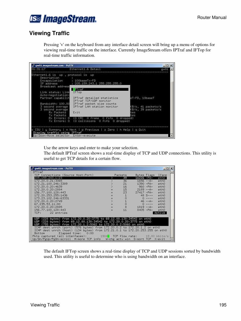
Viewing Traffic
Pressing 'v' on the keyboard from any interface detail screen will bring up a menu of options forviewing real-time traffic on the interface. Currently ImageStream offers IPTraf and IFTop forreal-time traffic information.
Use the arrow keys and enter to make your selection.The default IPTraf screen shows a real-time display of TCP and UDP connections. This utility isuseful to get TCP details for a certain flow.
The default IFTop screen shows a real-time display of TCP and UDP sessions sorted by bandwidthused. This utility is useful to determine who is using bandwidth on an interface.
Router Manual
Viewing Traffic 195
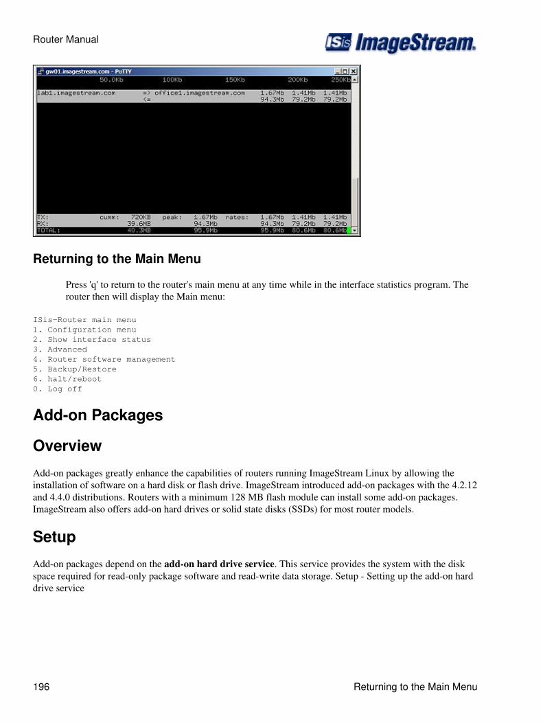
Returning to the Main Menu
Press 'q' to return to the router's main menu at any time while in the interface statistics program. Therouter then will display the Main menu:
ISis-Router main menu 1. Configuration menu 2. Show interface status 3. Advanced 4. Router software management 5. Backup/Restore 6. halt/reboot 0. Log off
Add-on Packages
Overview
Add-on packages greatly enhance the capabilities of routers running ImageStream Linux by allowing theinstallation of software on a hard disk or flash drive. ImageStream introduced add-on packages with the 4.2.12and 4.4.0 distributions. Routers with a minimum 128 MB flash module can install some add-on packages.ImageStream also offers add-on hard drives or solid state disks (SSDs) for most router models.
Setup
Add-on packages depend on the add-on hard drive service. This service provides the system with the diskspace required for read-only package software and read-write data storage. Setup - Setting up the add-on harddrive service
Router Manual
196 Returning to the Main Menu
Available add-on Packages
Apache Web Server• Asterisk• Netsweeper• Snort• Squid• Web Management Interface• Wireshark• Perl•
Troubleshooting
Introduction
This chapter presents general troubleshooting information and a discussion of tools and techniques fortroubleshooting serial connections.
The chapter includes the following topics:
Troubleshooting with the interface statistics detail screen◊ Serial Lines: Line Status Conditions◊ Serial Lines: Increasing Output Drops On Serial Link◊ Serial Lines: Increasing Input FIFO Buffer Drops on Serial Link◊ Serial Lines: Increasing Input Non-FIFO Buffer Drops on Serial Link◊ Serial Lines: Input Errors Of Over 1% Of Total Interface Traffic◊ Serial Lines: Troubleshooting Serial Line Input Errors◊ Serial Lines: Increasing Carrier Transitions Count on Serial Link◊ Troubleshooting Clocking Problems◊ Troubleshooting T1/E1 CSU/DSU Problems◊
Troubleshooting with the Interface Statistics Detail Screen
The output of the interface statistics detail screen displays information specific to the serial interfaceor subinterface. Please see the Chapter 27, Router Installation and Configuration Manual/Using TheInterface Statistics (stats) Program, for more information on accessing this program. The examplebelow shows the output of the detail page for a High-Level Data Link Control (HDLC) serialinterface.
The following section describes how to use this screen to diagnose serial line connectivity problemsin a wide area network (WAN) environment. The following sections describe some of the importantfields of the command output.
Serial Lines: Line Status Conditions
Serial Lines: Line Status Conditions
Router Manual
Available add-on Packages 197
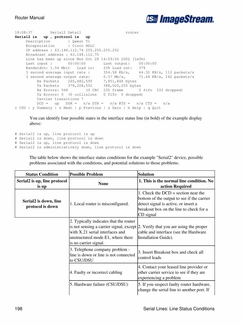
18:08:37 Serial2 Detail routerSerial2 is up , protocol is up Description : Qwest T1 Encapsulation : Cisco HDLC IP address : 63.148.112.74 255.255.255.252 Broadcast address : 63.148.112.75 Line has been up since Mon Oct 28 14:59:54 2002 (1w3h) Last input : 00:00:00 Last output: 00:00:00 Bandwidth: 1.54 Mbit Load in: 23% Load out: 37% 3 second average input rate : 354.58 Kb/s, 44.32 KB/s, 112 packets/s 3 second average output rate: 0.57 Mb/s, 71.64 KB/s, 142 packets/s Rx Packets 265,482,595 7,851,846 bytes Tx Packets 378,208,552 388,020,255 bytes Rx Errors: 568 (0 CRC 235 frame 0 fifo 333 dropped) Tx Errors: 0 (0 collisions 0 fifo 0 dropped) Carrier transitions 7 DCD = up DSR = n/a DTR = n/a RTS = n/a CTS = n/a c CSU | y Summary | n Next | p Previous | z Zero | h Help | q Quit
You can identify four possible states in the interface status line (in bold) of the example displayabove:
# Serial2 is up, line protocol is up # Serial2 is down, line protocol is down # Serial2 is up, line protocol is down # Serial2 is administratively down, line protocol is down
The table below shows the interface status conditions for the example "Serial2" device, possibleproblems associated with the conditions, and potential solutions to those problems.
Status Condition Possible Problem SolutionSerial2 is up, line protocol
is up None 1. This is the normal line condition. Noaction Required
Serial2 is down, lineprotocol is down 1. Local router is misconfigured.
1. Check the DCD = section near thebottom of the output to see if the carrierdetect signal is active, or insert abreakout box on the line to check for aCD signal
2. Typically indicates that the routeris not sensing a carrier signal, exceptwith X.21 serial interfaces andunstructured mode E1, where thereis no carrier signal.
2. Verify that you are using the propercable and interface (see the HardwareInstallation Guide).
3. Telephone company problem -line is down or line is not connectedto CSU/DSU
3. Insert Breakout box and check allcontrol leads
4. Faulty or incorrect cabling4. Contact your leased line provider orother carrier service to see if they areexperiencing a problem
5. Hardware failure (CSU/DSU) 5. If you suspect faulty router hardware,change the serial line to another port. If
Router Manual
198 Serial Lines: Line Status Conditions

the connection comes up, the previouslyconnected interface has a problem.
6. Swap faulty suspected parts.
Serial2 is up, line protocolis down
1. Local or remote router ismisconfigured
1. Insert a loopback plug into theCSU/DSU (or crossover the coaxial cablefrom the transmit side to the receive side)and see if the router receives its ownpackets normally. You should see areceived packet for each transmittedpacket.
2. Remote router is not using IEFTframe relay (when using frame relayencapsulation
2. If data is being received normally, atelephone company problem or amisconfigured/failed remote router is thelikely problem
3. Remote router is not using properATM encapsulation (when usingATM encapsulation)
3. If problem appears to be on the remoteend, repeat Step 1 on the remoteCSU/DSU.
4. Keepalives are not being sent byremote router
4. Verify all cabling. Make sure that thecable is attached to the correct interface,the correct CSU/DSU, and the correcttelephone company network terminalpoint
5. Leased line provider or othercarrier service problem - Noisy line,or misconfigured or failed switch
5. Enable debug protocol command inthe interface configuration. The debugprotocol command displays all protocolnegotiation packets to the router's debuglog, available from the "Advanced Menu"
Caution: because debugging output isassigned a high priority in the CPUprocess, it can use considerable systemresources. For this reason, the use of thedebug command should be limited totroubleshooting specific problems orduring troubleshooting sessions withImageStream's technical supportpersonnel during periods of low networktraffic or when fewer users are expected.
6.Failed local or remote CSU/DSU6. If the port does not receive its ownpackets back when looped, a routerhardware problem is likely.
7. Router hardware failure (local orremote)
7. If you suspect faulty router hardware,change the serial line to an unused port. Ifthe connection comes up, the previousconnected interface is experiencing aproblem.
Router Manual
Serial Lines: Line Status Conditions 199
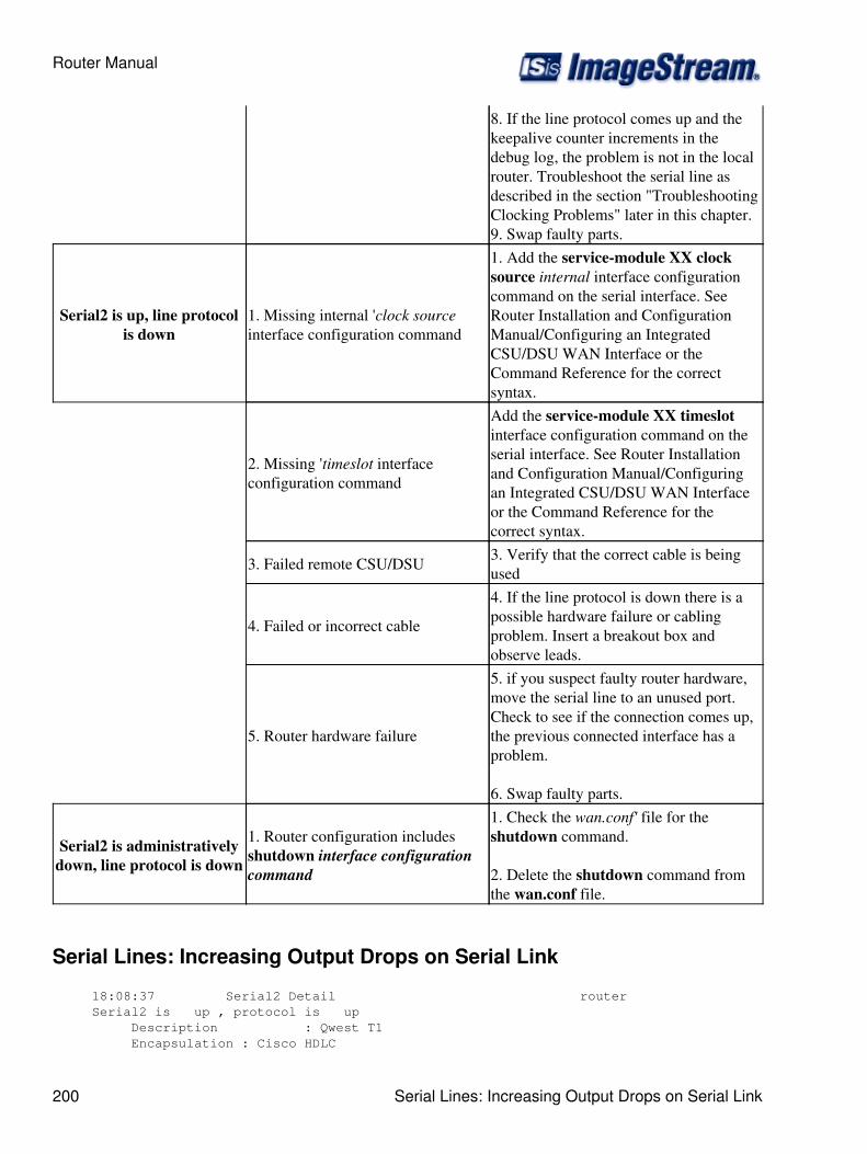
8. If the line protocol comes up and thekeepalive counter increments in thedebug log, the problem is not in the localrouter. Troubleshoot the serial line asdescribed in the section "TroubleshootingClocking Problems" later in this chapter.9. Swap faulty parts.
Serial2 is up, line protocolis down
1. Missing internal 'clock sourceinterface configuration command
1. Add the service-module XX clocksource internal interface configurationcommand on the serial interface. SeeRouter Installation and ConfigurationManual/Configuring an IntegratedCSU/DSU WAN Interface or theCommand Reference for the correctsyntax.
2. Missing 'timeslot interfaceconfiguration command
Add the service-module XX timeslotinterface configuration command on theserial interface. See Router Installationand Configuration Manual/Configuringan Integrated CSU/DSU WAN Interfaceor the Command Reference for thecorrect syntax.
3. Failed remote CSU/DSU 3. Verify that the correct cable is beingused
4. Failed or incorrect cable
4. If the line protocol is down there is apossible hardware failure or cablingproblem. Insert a breakout box andobserve leads.
5. Router hardware failure
5. if you suspect faulty router hardware,move the serial line to an unused port.Check to see if the connection comes up,the previous connected interface has aproblem.
6. Swap faulty parts.
Serial2 is administrativelydown, line protocol is down
1. Router configuration includesshutdown interface configurationcommand
1. Check the wan.conf' file for theshutdown command.
2. Delete the shutdown command fromthe wan.conf file.
Serial Lines: Increasing Output Drops on Serial Link
18:08:37 Serial2 Detail router Serial2 is up , protocol is up Description : Qwest T1 Encapsulation : Cisco HDLC
Router Manual
200 Serial Lines: Increasing Output Drops on Serial Link
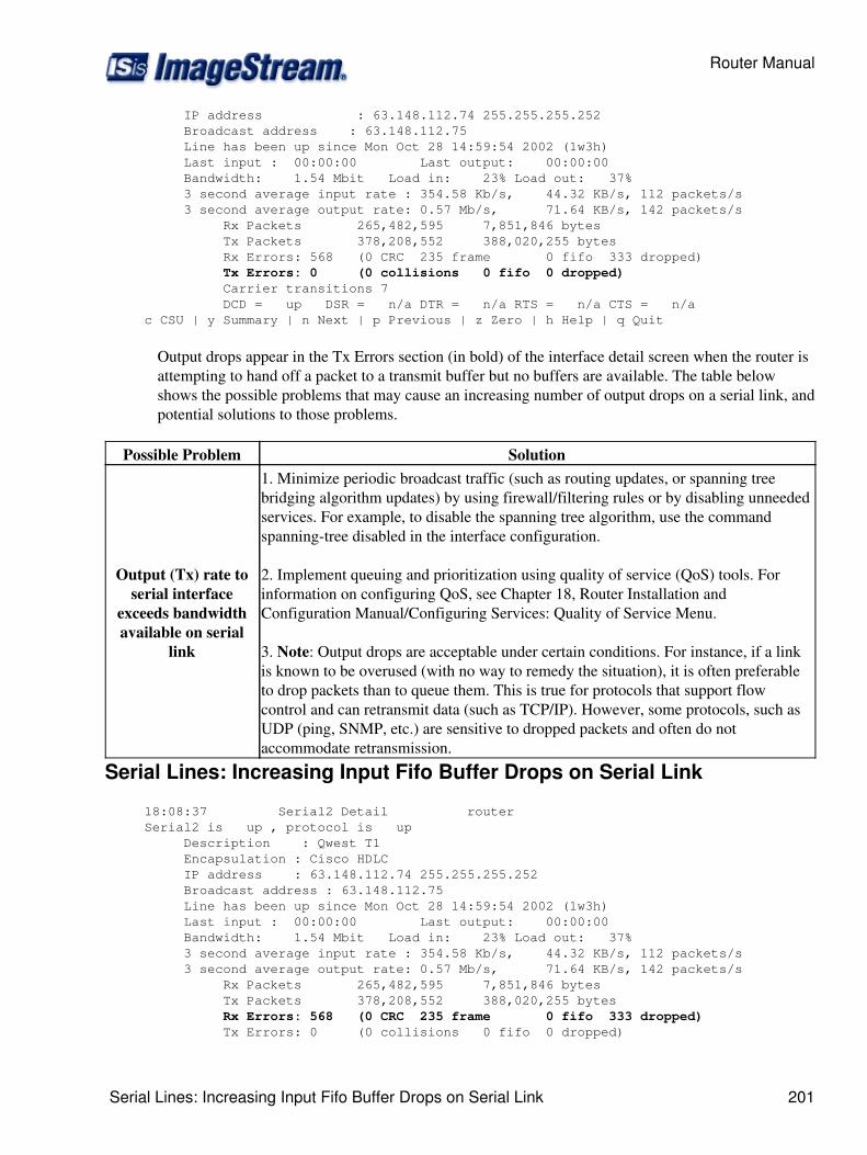
IP address : 63.148.112.74 255.255.255.252 Broadcast address : 63.148.112.75 Line has been up since Mon Oct 28 14:59:54 2002 (1w3h) Last input : 00:00:00 Last output: 00:00:00 Bandwidth: 1.54 Mbit Load in: 23% Load out: 37% 3 second average input rate : 354.58 Kb/s, 44.32 KB/s, 112 packets/s 3 second average output rate: 0.57 Mb/s, 71.64 KB/s, 142 packets/s Rx Packets 265,482,595 7,851,846 bytes Tx Packets 378,208,552 388,020,255 bytes Rx Errors: 568 (0 CRC 235 frame 0 fifo 333 dropped)
Tx Errors: 0 (0 collisions 0 fifo 0 dropped) Carrier transitions 7 DCD = up DSR = n/a DTR = n/a RTS = n/a CTS = n/a c CSU | y Summary | n Next | p Previous | z Zero | h Help | q Quit
Output drops appear in the Tx Errors section (in bold) of the interface detail screen when the router isattempting to hand off a packet to a transmit buffer but no buffers are available. The table belowshows the possible problems that may cause an increasing number of output drops on a serial link, andpotential solutions to those problems.
Possible Problem Solution
Output (Tx) rate toserial interface
exceeds bandwidthavailable on serial
link
1. Minimize periodic broadcast traffic (such as routing updates, or spanning treebridging algorithm updates) by using firewall/filtering rules or by disabling unneededservices. For example, to disable the spanning tree algorithm, use the commandspanning-tree disabled in the interface configuration.
2. Implement queuing and prioritization using quality of service (QoS) tools. Forinformation on configuring QoS, see Chapter 18, Router Installation andConfiguration Manual/Configuring Services: Quality of Service Menu.
3. Note: Output drops are acceptable under certain conditions. For instance, if a linkis known to be overused (with no way to remedy the situation), it is often preferableto drop packets than to queue them. This is true for protocols that support flowcontrol and can retransmit data (such as TCP/IP). However, some protocols, such asUDP (ping, SNMP, etc.) are sensitive to dropped packets and often do notaccommodate retransmission.
Serial Lines: Increasing Input Fifo Buffer Drops on Serial Link
18:08:37 Serial2 Detail router Serial2 is up , protocol is up Description : Qwest T1 Encapsulation : Cisco HDLC IP address : 63.148.112.74 255.255.255.252 Broadcast address : 63.148.112.75 Line has been up since Mon Oct 28 14:59:54 2002 (1w3h) Last input : 00:00:00 Last output: 00:00:00 Bandwidth: 1.54 Mbit Load in: 23% Load out: 37% 3 second average input rate : 354.58 Kb/s, 44.32 KB/s, 112 packets/s 3 second average output rate: 0.57 Mb/s, 71.64 KB/s, 142 packets/s Rx Packets 265,482,595 7,851,846 bytes Tx Packets 378,208,552 388,020,255 bytes
Rx Errors: 568 (0 CRC 235 frame 0 fifo 333 dropped) Tx Errors: 0 (0 collisions 0 fifo 0 dropped)
Router Manual
Serial Lines: Increasing Input Fifo Buffer Drops on Serial Link 201

Carrier transitions 7 DCD = up DSR = n/a DTR = n/a RTS = n/a CTS = n/a c CSU | y Summary | n Next | p Previous | z Zero | h Help | q Quit
Input FIFO buffer drops appear in the Rx Errors section (in bold) of the interface detail screen whentoo many packets from that interface are being processed by the router. The table below shows thepossible problems that may cause an increasing number of input drops on a serial link, and potentialsolutions to those problems.
Possible Problem Solution
Input rate exceedsthe capacity of the
router or inputqueues exceed the
size of output queues
1. Note: Input drop problems are typically seen when traffic is being routed betweenfaster interfaces (such as Ethernet and serial interfaces). When traffic is light, nodrops occur. As traffic rates increase, packet backlogs start occurring. Routers droppackets during these congested periods.
2. Implement queuing and prioritization using Quality of Service(QoS) tools. Forinformation on configuring QoS, see Router Installation andConfiguration/Configuring Services: Quality of Service Menu.
3. Note: Input drops are acceptable under certain conditions. For instance, if a link isknown to be overused (with no way to remedy the situation), it is often preferable todrop packets than to queue them. This is true for protocols that support flow controland can retransmit data (such as TCP/IP). However, some protocols, such as UDP(ping, SNMP, etc.) are sensitive to dropped packets and often do not accommodateretransmission.
Serial Lines: Increasing Non-Fifo Input Drops on Serial Link
18:08:37 Serial2 Detail router Serial2 is up , protocol is up Description : Qwest T1 Encapsulation : Cisco HDLC IP address : 63.148.112.74 255.255.255.252 Broadcast address : 63.148.112.75 Line has been up since Mon Oct 28 14:59:54 2002 (1w3h) Last input : 00:00:00 Last output: 00:00:00 Bandwidth: 1.54 Mbit Load in: 23% Load out: 37% 3 second average input rate : 354.58 Kb/s, 44.32 KB/s, 112 packets/s 3 second average output rate: 0.57 Mb/s, 71.64 KB/s, 142 packets/s Rx Packets 265,482,595 7,851,846 bytes Tx Packets 378,208,552 388,020,255 bytes
Rx Errors: 568 (0 CRC 235 frame 0 fifo 333 dropped) Tx Errors: 0 (0 collisions 0 fifo 0 dropped) Carrier transitions 7 DCD = up DSR = n/a DTR = n/a RTS = n/a CTS = n/a c CSU | y Summary | n Next | p Previous | z Zero | h Help | q Quit
Non-FIFO input drops appear in the Rx Errors section (in bold) of the interface detail screen when therouter receives a packet that cannot be processed. The table below shows the possible problems thatmay cause an increasing number of non-FIFO input drops on a serial link, and potential solutions tothose problems.
Router Manual
202 Serial Lines: Increasing Non-Fifo Input Drops on Serial Link
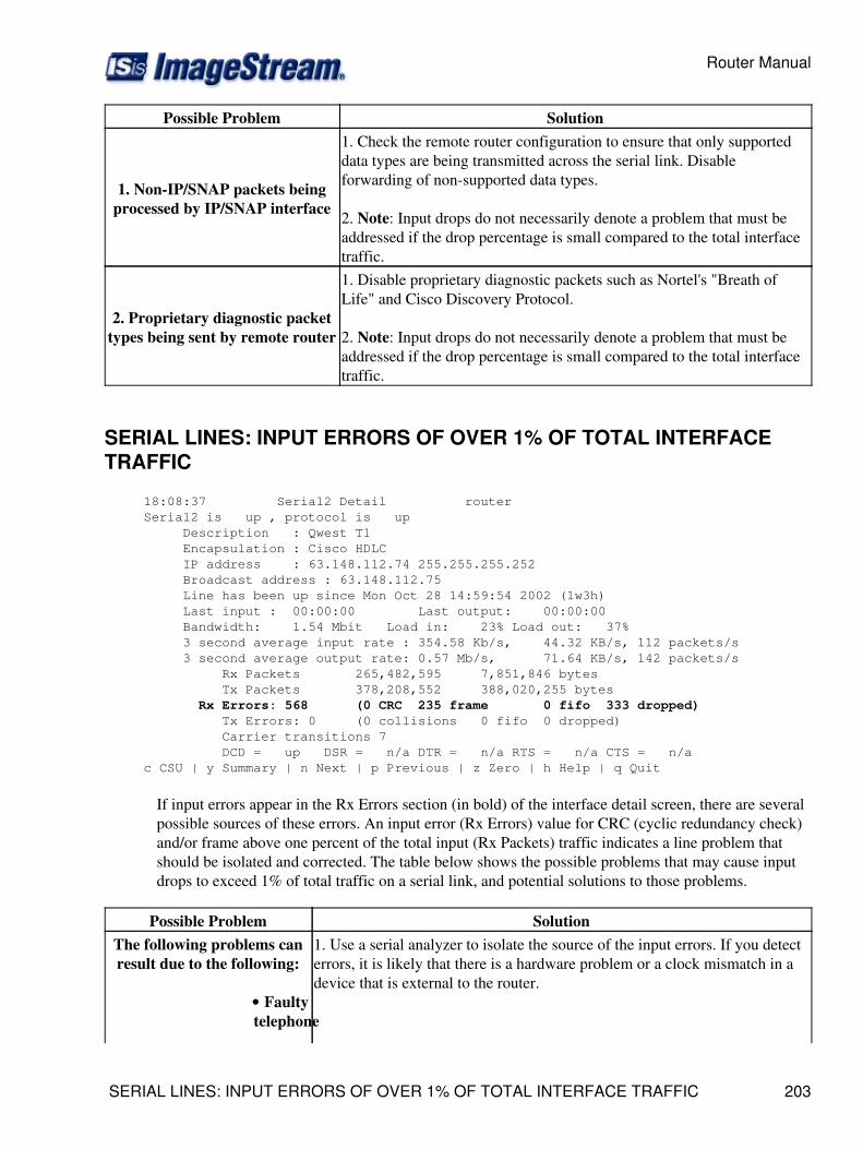
Possible Problem Solution
1. Non-IP/SNAP packets beingprocessed by IP/SNAP interface
1. Check the remote router configuration to ensure that only supporteddata types are being transmitted across the serial link. Disableforwarding of non-supported data types.
2. Note: Input drops do not necessarily denote a problem that must beaddressed if the drop percentage is small compared to the total interfacetraffic.
2. Proprietary diagnostic packettypes being sent by remote router
1. Disable proprietary diagnostic packets such as Nortel's "Breath ofLife" and Cisco Discovery Protocol.
2. Note: Input drops do not necessarily denote a problem that must beaddressed if the drop percentage is small compared to the total interfacetraffic.
SERIAL LINES: INPUT ERRORS OF OVER 1% OF TOTAL INTERFACETRAFFIC
18:08:37 Serial2 Detail router Serial2 is up , protocol is up Description : Qwest T1 Encapsulation : Cisco HDLC IP address : 63.148.112.74 255.255.255.252 Broadcast address : 63.148.112.75 Line has been up since Mon Oct 28 14:59:54 2002 (1w3h) Last input : 00:00:00 Last output: 00:00:00 Bandwidth: 1.54 Mbit Load in: 23% Load out: 37% 3 second average input rate : 354.58 Kb/s, 44.32 KB/s, 112 packets/s 3 second average output rate: 0.57 Mb/s, 71.64 KB/s, 142 packets/s Rx Packets 265,482,595 7,851,846 bytes Tx Packets 378,208,552 388,020,255 bytes
Rx Errors: 568 (0 CRC 235 frame 0 fifo 333 dropped) Tx Errors: 0 (0 collisions 0 fifo 0 dropped) Carrier transitions 7 DCD = up DSR = n/a DTR = n/a RTS = n/a CTS = n/a c CSU | y Summary | n Next | p Previous | z Zero | h Help | q Quit
If input errors appear in the Rx Errors section (in bold) of the interface detail screen, there are severalpossible sources of these errors. An input error (Rx Errors) value for CRC (cyclic redundancy check)and/or frame above one percent of the total input (Rx Packets) traffic indicates a line problem thatshould be isolated and corrected. The table below shows the possible problems that may cause inputdrops to exceed 1% of total traffic on a serial link, and potential solutions to those problems.
Possible Problem SolutionThe following problems canresult due to the following:
Faultytelephone•
1. Use a serial analyzer to isolate the source of the input errors. If you detecterrors, it is likely that there is a hardware problem or a clock mismatch in adevice that is external to the router.
Router Manual
SERIAL LINES: INPUT ERRORS OF OVER 1% OF TOTAL INTERFACE TRAFFIC 203

orcompany
equipmentNoisyserialline
•
Incorrectclocking
configuration
•
Incorrectcable
orcabletoo
long
•
Faultycable
orconnection
•
FaultyCSU/DSU•
Faultyrouter
hardware
•
Improperor
malfunctioningmedia
converter
•
linetap orotherdevicebeingused
betweenrouter
andCSU/DSU
•
2. Use a loopback plug (or cross over a coaxial cable) to isolate the routerand CSU/DSU from the telephone company equipment or other carrierequipment.
3. Look for patterns. For example, if errors occur at consistent intervals, theycould be related to a periodic function such as the sending of routing updatesor broadcast traffic.
4. Check for any errors or alarms on the telephone company equipment orother carrier equipment.
5. If the problem can be isolated to the telephone company equipment orother carrier equipment, ask your provider to fully test the line. If simpleautomated tests do not locate the problem, ask the provider to run thefollowing tests in order:
All 0's for 5-20 minutes with no errors:• All 1's for 5-20 minutes with no errors:• Quasi-random word (QRW) for 5-20 minutes withno errors
•
Serial Lines: Troubleshooting Serial Line Input Errors
18:08:37 Serial2 Detail router Serial2 is up , protocol is up Description : Qwest T1 Encapsulation : Cisco HDLC IP address : 63.148.112.74 255.255.255.252 Broadcast address : 63.148.112.75
Router Manual
204 Serial Lines: Troubleshooting Serial Line Input Errors

Line has been up since Mon Oct 28 14:59:54 2002 (1w3h) Last input : 00:00:00 Last output: 00:00:00 Bandwidth: 1.54 Mbit Load in: 23% Load out: 37% 3 second average input rate : 354.58 Kb/s, 44.32 KB/s, 112 packets/s 3 second average output rate: 0.57 Mb/s, 71.64 KB/s, 142 packets/s Rx Packets 265,482,595 7,851,846 bytes Tx Packets 378,208,552 388,020,255 bytes
Rx Errors: 568 (0 CRC 235 frame 0 fifo 333 dropped) Tx Errors: 0 (0 collisions 0 fifo 0 dropped) Carrier transitions 7 DCD = up DSR = n/a DTR = n/a RTS = n/a CTS = n/a c CSU | y Summary | n Next | p Previous | z Zero | h Help | q Quit
If input errors appear in the Rx Errors section (in bold) of the interface detail screen, there are severalpossible problems that may be causing these errors. The table below shows the possible problems thatmay cause input drops to exceed 1% of total traffic on a serial link, and potential solutions to thoseproblems.
Input ErrorType Possible Problem Solution
CRC errors(CRC)
Cyclic Redundancy Check errors occurwhen the CRC calculation produces anerror-indicating that data iscorrupted-for one of the followingreasons:
Noisy serialline
•
Serial cable istoo long, or thecable is notshielded(interference orsignal lossproblems)
•
CSU/DSUclocking isincorrectlyconfigured
•
"Ones density"problem on T1link (incorrectframing orencodingconfiguration)
•
1. Ensure that the line is clean enough for transmissionrequirements. Shield the cable if necessary.
2. Make sure the cable is within the recommendedlength - ideally, no more than 50 feet (15.24 meters)from the telephone company or carrier equipment.
3. Make sure the cable between the CSU/DSU and therouter is within the recommended length - ideally, nomore than 25 feet (7.62 meters) for V.35.
4. Ensure that all devices are properly configured for acommon and single line clock. Each line must haveone and only one clock source configured on alldevices. In most cases, the leased line provider willprovide the clocking for the line.
5. Make certain that the local and remote CSU/DSU'sare configured for the same framing and encodingscheme as that used by the leased-line or other carrierservice (for example, ESF/B8ZS or CCS/HDB3).
6. Contact your leased-line or other carrier service andhave it perform integrity tests on the line. If simpleautomated tests do not locate the problem, ask theprovider to run the following tests in order:
All 0's for 5-20 minutes withno errors
•
Router Manual
Serial Lines: Troubleshooting Serial Line Input Errors 205
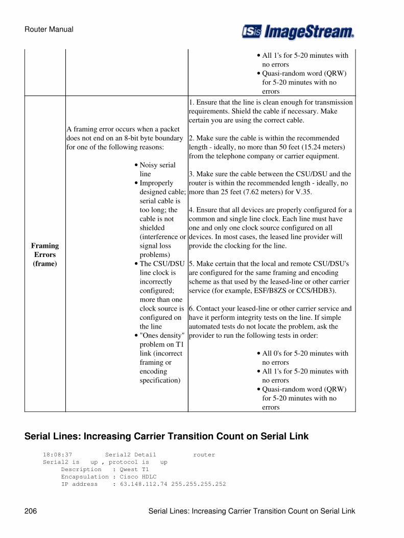
All 1's for 5-20 minutes withno errors
•
Quasi-random word (QRW)for 5-20 minutes with noerrors
•
FramingErrors(frame)
A framing error occurs when a packetdoes not end on an 8-bit byte boundaryfor one of the following reasons:
Noisy serialline
•
Improperlydesigned cable;serial cable istoo long; thecable is notshielded(interference orsignal lossproblems)
•
The CSU/DSUline clock isincorrectlyconfigured;more than oneclock source isconfigured onthe line
•
"Ones density"problem on T1link (incorrectframing orencodingspecification)
•
1. Ensure that the line is clean enough for transmissionrequirements. Shield the cable if necessary. Makecertain you are using the correct cable.
2. Make sure the cable is within the recommendedlength - ideally, no more than 50 feet (15.24 meters)from the telephone company or carrier equipment.
3. Make sure the cable between the CSU/DSU and therouter is within the recommended length - ideally, nomore than 25 feet (7.62 meters) for V.35.
4. Ensure that all devices are properly configured for acommon and single line clock. Each line must haveone and only one clock source configured on alldevices. In most cases, the leased line provider willprovide the clocking for the line.
5. Make certain that the local and remote CSU/DSU'sare configured for the same framing and encodingscheme as that used by the leased-line or other carrierservice (for example, ESF/B8ZS or CCS/HDB3).
6. Contact your leased-line or other carrier service andhave it perform integrity tests on the line. If simpleautomated tests do not locate the problem, ask theprovider to run the following tests in order:
All 0's for 5-20 minutes withno errors
•
All 1's for 5-20 minutes withno errors
•
Quasi-random word (QRW)for 5-20 minutes with noerrors
•
Serial Lines: Increasing Carrier Transition Count on Serial Link
18:08:37 Serial2 Detail router Serial2 is up , protocol is up Description : Qwest T1 Encapsulation : Cisco HDLC IP address : 63.148.112.74 255.255.255.252
Router Manual
206 Serial Lines: Increasing Carrier Transition Count on Serial Link
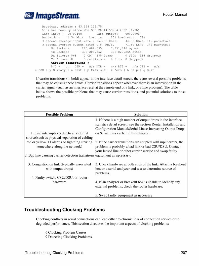
Broadcast address : 63.148.112.75 Line has been up since Mon Oct 28 14:59:54 2002 (1w3h) Last input : 00:00:00 Last output: 00:00:00 Bandwidth: 1.54 Mbit Load in: 23% Load out: 37% 3 second average input rate : 354.58 Kb/s, 44.32 KB/s, 112 packets/s 3 second average output rate: 0.57 Mb/s, 71.64 KB/s, 142 packets/s Rx Packets 265,482,595 7,851,846 bytes Tx Packets 378,208,552 388,020,255 bytes Rx Errors: 568 (0 CRC 235 frame 0 fifo 333 dropped) Tx Errors: 0 (0 collisions 0 fifo 0 dropped)
Carrier transitions 7 DCD = up DSR = n/a DTR = n/a RTS = n/a CTS = n/a c CSU | y Summary | n Next | p Previous | z Zero | h Help | q Quit
If carrier transitions (in bold) appear in the interface detail screen, there are several possible problemsthat may be causing these errors. Carrier transitions appear whenever there is an interruption in thecarrier signal (such as an interface reset at the remote end of a link, or a line problem). The tablebelow shows the possible problems that may cause carrier transitions, and potential solutions to thoseproblems.
Possible Problem Solution
1. Line interruptions due to an externalsource(such as physical separation of cablingred or yellow T1 alarms or lightning striking
somewhere along the network)
2. Bad line causing carrier detection transitions
3. Congestion on link (typically associatedwith output drops)
4. Faulty switch, CSU/DSU, or routerhardware
1. If there is a high number of output drops in the interfacestatistics detail screen, see the section Router Installation andConfiguration Manual/Serial Lines: Increasing Output Dropson Serial Link earlier in this chapter.
2. If the carrier transitions are coupled with input errors, theproblem is probably a bad link or bad CSU/DSU. Contactyour leased line or other carrier service and swap faultyequipment as necessary.
3. Check hardware at both ends of the link. Attach a breakoutbox or a serial analyzer and test to determine source ofproblems.
4. If an analyzer or breakout box is unable to identify anyexternal problems, check the router hardware.
5. Swap faulty equipment as necessary.
Troubleshooting Clocking Problems
Clocking conflicts in serial connections can lead either to chronic loss of connection service or todegraded performance. This section discusses the important aspects of clocking problems:
Clocking Problem Causes◊ Detecting Clocking Problems◊
Router Manual
Troubleshooting Clocking Problems 207

Isolating Clocking Problems◊ Clocking Problem Solutions.◊
Clocking Overview
The CSU/DSU derives the data clock from the data that passes through it. In order to recover theclock, the CSU/DSU hardware must receive at least one 1-bit value for every 8 bits of data that passthrough it; this is known as "ones density". Maintaining ones density allows the hardware to recoverthe data clock reliably.
Newer T1 implementations commonly use Extended Superframe Format (ESF) framing with binaryeight-zero substitution (B8ZS) coding. B8ZS provides a scheme by which a special code is substitutedwhenever eight consecutive zeros are sent through the serial link. This code is then interpreted at theremote end of the connection. This technique guarantees ones density independent of the data stream.
Older T1 implementations use D4-also known as Superframe Format (SF) framing and AlternateMark Inversion (AMI) coding. AMI does not utilize a coding scheme like B8ZS. This restricts thetype of data that can be transmitted because ones density is not maintained independent of the datastream.
Obviously, the line can have only one timing source. If more than one data clock exists on a line,synchronization of frames is impossible and line errors will result. If no data clock exists, similarproblems result.
Clocking Problem Causes
In general, clocking problems in serial WAN interconnections can be attributed to one of thefollowing causes:
Incorrect CSU/DSU configuration1. Multiple or no clock source2. Cables out of specification-that is, longer than 50 feet (15.24 meters) or unshielded3. Noisy or poor patch panel connections4. Several cables connected together in a row5.
Detecting Clocking Problems
To detect clocking conflicts on a serial interface, look for input errors as follows:
Use the interface statistics program on the routers at both ends of the link.1. Examine the detail screen output for CRC, framing errors, and fifo drops.2. If either of these steps indicates errors exceeding approximately 1 percent of traffic on the3.
Router Manual
208 Troubleshooting Clocking Problems
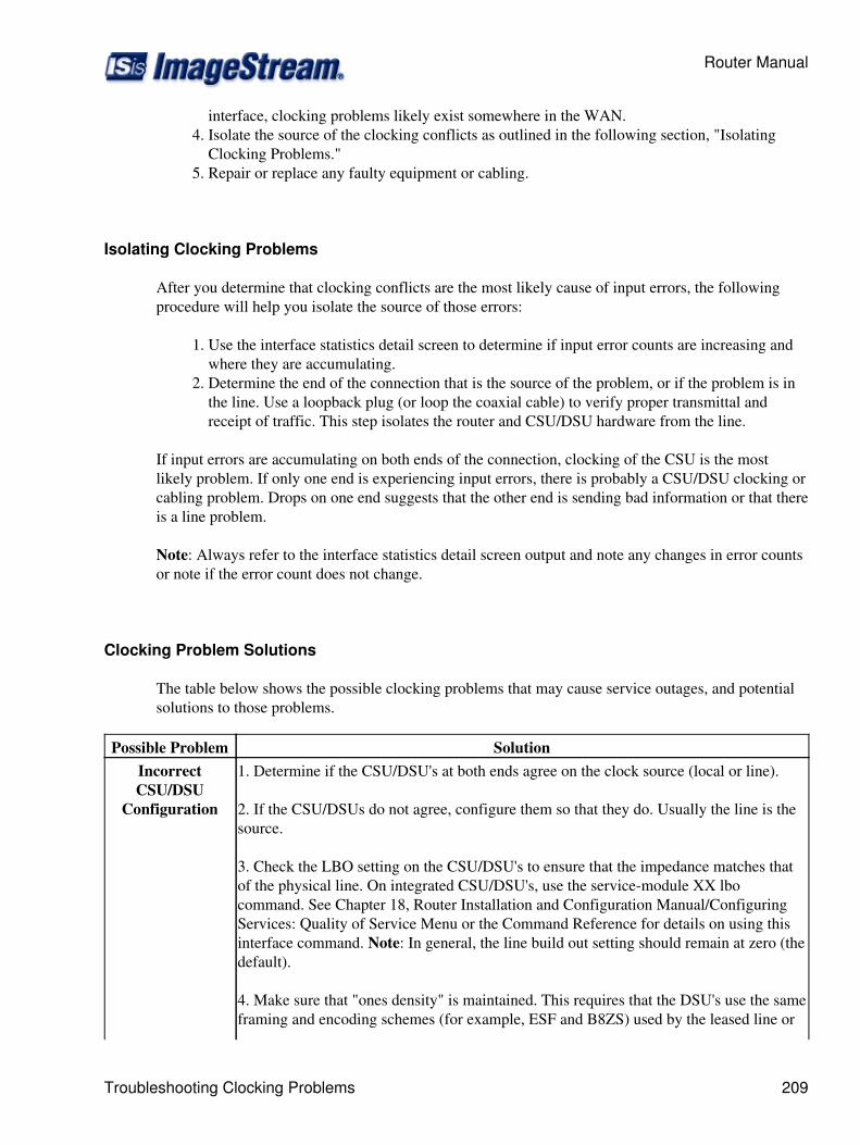
interface, clocking problems likely exist somewhere in the WAN.Isolate the source of the clocking conflicts as outlined in the following section, "IsolatingClocking Problems."
4.
Repair or replace any faulty equipment or cabling.5.
Isolating Clocking Problems
After you determine that clocking conflicts are the most likely cause of input errors, the followingprocedure will help you isolate the source of those errors:
Use the interface statistics detail screen to determine if input error counts are increasing andwhere they are accumulating.
1.
Determine the end of the connection that is the source of the problem, or if the problem is inthe line. Use a loopback plug (or loop the coaxial cable) to verify proper transmittal andreceipt of traffic. This step isolates the router and CSU/DSU hardware from the line.
2.
If input errors are accumulating on both ends of the connection, clocking of the CSU is the mostlikely problem. If only one end is experiencing input errors, there is probably a CSU/DSU clocking orcabling problem. Drops on one end suggests that the other end is sending bad information or that thereis a line problem.
Note: Always refer to the interface statistics detail screen output and note any changes in error countsor note if the error count does not change.
Clocking Problem Solutions
The table below shows the possible clocking problems that may cause service outages, and potentialsolutions to those problems.
Possible Problem SolutionIncorrectCSU/DSU
Configuration
1. Determine if the CSU/DSU's at both ends agree on the clock source (local or line).
2. If the CSU/DSUs do not agree, configure them so that they do. Usually the line is thesource.
3. Check the LBO setting on the CSU/DSU's to ensure that the impedance matches thatof the physical line. On integrated CSU/DSU's, use the service-module XX lbocommand. See Chapter 18, Router Installation and Configuration Manual/ConfiguringServices: Quality of Service Menu or the Command Reference for details on using thisinterface command. Note: In general, the line build out setting should remain at zero (thedefault).
4. Make sure that "ones density" is maintained. This requires that the DSU's use the sameframing and encoding schemes (for example, ESF and B8ZS) used by the leased line or
Router Manual
Troubleshooting Clocking Problems 209
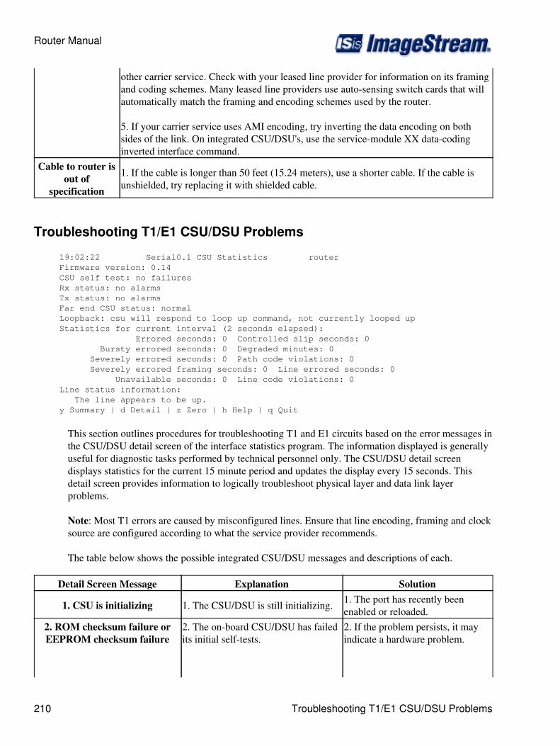
other carrier service. Check with your leased line provider for information on its framingand coding schemes. Many leased line providers use auto-sensing switch cards that willautomatically match the framing and encoding schemes used by the router.
5. If your carrier service uses AMI encoding, try inverting the data encoding on bothsides of the link. On integrated CSU/DSU's, use the service-module XX data-codinginverted interface command.
Cable to router isout of
specification
1. If the cable is longer than 50 feet (15.24 meters), use a shorter cable. If the cable isunshielded, try replacing it with shielded cable.
Troubleshooting T1/E1 CSU/DSU Problems
19:02:22 Serial0.1 CSU Statistics router Firmware version: 0.14 CSU self test: no failures Rx status: no alarms Tx status: no alarms Far end CSU status: normal Loopback: csu will respond to loop up command, not currently looped up Statistics for current interval (2 seconds elapsed): Errored seconds: 0 Controlled slip seconds: 0 Bursty errored seconds: 0 Degraded minutes: 0 Severely errored seconds: 0 Path code violations: 0 Severely errored framing seconds: 0 Line errored seconds: 0 Unavailable seconds: 0 Line code violations: 0 Line status information: The line appears to be up. y Summary | d Detail | z Zero | h Help | q Quit
This section outlines procedures for troubleshooting T1 and E1 circuits based on the error messages inthe CSU/DSU detail screen of the interface statistics program. The information displayed is generallyuseful for diagnostic tasks performed by technical personnel only. The CSU/DSU detail screendisplays statistics for the current 15 minute period and updates the display every 15 seconds. Thisdetail screen provides information to logically troubleshoot physical layer and data link layerproblems.
Note: Most T1 errors are caused by misconfigured lines. Ensure that line encoding, framing and clocksource are configured according to what the service provider recommends.
The table below shows the possible integrated CSU/DSU messages and descriptions of each.
Detail Screen Message Explanation Solution
1. CSU is initializing 1. The CSU/DSU is still initializing. 1. The port has recently beenenabled or reloaded.
2. ROM checksum failure orEEPROM checksum failure
2. The on-board CSU/DSU has failedits initial self-tests.
2. If the problem persists, it mayindicate a hardware problem.
Router Manual
210 Troubleshooting T1/E1 CSU/DSU Problems

Contact ImageStream technicalsupport for assistance.
3. Framer type is incorrect,Framer hardware failure or
Internal loopback failure
3. The CSU/DSU has failed itsinternal loopback test.
3. If the problem persists, it mayindicate a hardware problem.
Contact ImageStream technicalsupport for assistance.
An internal loopback failure aloneis generally not the cause of a lineproblem.
4. CSU will respond to loop upcommand, not currently looped
up
4. The CSU/DSU has passed its initialself-tests and is operational.
4. The CSU/DSU is ready toaccept loop up commands, but isnot currently in a loopback state.
This is the most common state ofthe CSU/DSU.
5. Your CSU is currently loopedup. No data can be received byyour router while the CSU is
looped up.
5. The CSU/DSU has received a"loop up" command from a remotedevice or test set.
5. The CSU/DSU is currently in apayload loopback mode and isreflecting all received data back tothe network.
The router will receive no datafrom th integrated CSU/DSU whileit is in payload loopback mode.
6. RAI - remote alarmindication (yellow alarm) on Rx
Status
6. The CSU/DSU is receiving a signalfrom the remote end that the remoteCSU/DSU has lost signal
6. If there are no local errors(AIS,LOS,OOF), this indicates aproblem at the far end and not withthe local CSU/DSU.
The line is generally down if ayellow alarm is encountered andindicates a remote problem.
7. RAI - remote alarmindication (yellow alarm) on Tx
Status
7. The CSU/DSU transmitting asignal to the remote end that the localCSU/DSU has lost signal.
7. Other local errors (AIS, LOS,OOF) will accompany this TxStatus error.
The other local errors will indicatethe nature of the problem that thelocal CSU/DSU is having with theremote end.
8. AIS - alarm indication signal(blue alarm)
8. The CSU/DSU is transmittingand/or receiving a continuity signal toindicate that there is a transmissionfault upstream of the CSU/DSU.
8. The line is down if a blue alarmis encountered and generallyindicates a line problem
Check to see that the framingformat configuration on the
Router Manual
Troubleshooting T1/E1 CSU/DSU Problems 211

CSU/DSU matches the format usedon the line
If the problem persists, contact theleased line provider for additionalassistance.
9. PDE - pulse density error9. The CSU/DSU is not transmittingand/or receiving at least one pulse inevery 8 bits from the line
9. This error often appears alongwith a yellow alarm, and indicatesthat the line is down due to aremote problem.
10. LOS - loss of signal10. The CSU/DSU has not received apulse in 175 consecutive pulsepositions
10. This error, also referred to as ared alarm, usually indicates that theCSU/DSU has lost connectivitywith the local loop of the leasedline.
Often this error occurs because theCSU/DSU has been disconnectedfrom the line. LOS is a localproblem and not with the far endCSU/DSU.
Make sure that the cable betweenthe CSU/DSU and the T1 or E1terminal equipment is connectedcorrectly.
Check to see that the cable isconnected to the correct ports.
Check cable integrity. Look forbreaks or other physicalabnormalities in the cable. Overshort distances, it is acceptable touse a standard, straight-throughCat3 or Cat5 Ethernet cable insteadof a standard T1 or E1 cable.
11. OOF - out of frame
11. The CSU/DSU has received 4consecutive frames out of alignment.This error generally indicates aclocking or framing problem.
11. Check to see that the framingformat configuration on theCSU/DSU matches the format usedon the line and on the remoteCSU/DSU.
Check the line buildout setting inthe interface configuration file(wan.conf).
12. PRM - performance report 12. The remote CSU/DSU is not 12. this error by itself does not
Router Manual
212 Troubleshooting T1/E1 CSU/DSU Problems

monitoring failure reporting performance data. indicate a problem with the line, assome equipment does not providePRM data, or has the servicedisabled.
13. Payload loopback
13. The remote CSU/DSU hasreceived a loop up command and isreflecting received data back onto thelink.
Troubleshooting Ethernet Problems
To view LAN station traffic on an interface the Interface Status utility (stats) has a special option indetail mode which will show traffic by Ethernet MAC adddress.Run the interface status utility (option 2 from the main menu) and get detail on the interface you wantto view LAN station traffic.Hit v (the view command) to bring up the view traffic dialog box.Use the arrow keys or hit L to select 'IPTraf LAN station monitor'
13:44:47 Ethernet0 Detail inside-envoy-------------------------------------------------------------------------------Ethernet0 is up , protocol is up Description : 100Mb Ethernet Encapsulation : 100baseTx-FD IP address : 192.168.100.2 255.255.255.0 Broadcast address : 192.168.100.255
Link status: Link beat established Auto-negotiation: enabled (100baseTx-FD) Partner capabilities: 100baseTx-FD, 100baseTx, 10baseT-FD, 10baseT
Bandwidth: 100.00 Mbit Load in: 0% Load out: 1% 3 second average input rate : 0.31 Mb/s, 38.32 KB/s, 198 packets/s 3 second average output rate: 1.67 Mb/s, 0.21 MB/s, 214 packets/s Rx Packets 324,136 45,150,440 bytes Tx Packets 286,121 125,045,304 bytes Rx Errors: 0 (0 CRC 0 frame 0 fifo 0 dropped) Tx Errors: 0??????????????????????????????????? ? IPTraf ?----------------------? IFTop ?----------------------c CSU | y Summary | n ??????????????????????????????????? ? IPTraf detailed statistics ? ? IPTraf TCP/UDP monitor ? ? IPTraf packet size counts ? ? IPTraf LAN station monitor ? ??????????????????????????????????? ? Exit ? ???????????????????????????????????
IPTraf????? PktsIn ??? IP In ? BytesIn ? InRate PktsOut ?? IP Out BytesOut OutRate ?? ? 30 0 3120 0.8 0 0 0 0.0 ?? Ethernet HW addr: 0019d1799ae9 on eth0 ?
Router Manual
Troubleshooting Ethernet Problems 213

? ? 30 0 14531 0.0 36 0 8235 0.0 ?? Ethernet HW addr: 0019d1758fa3 on eth0 ?? ? 11 0 881 0.0 11 0 805 0.0 ?? Ethernet HW addr: 000b821e874a on eth0 ?? ? 0 0 0 0.0 2 0 92 0.0 ?? Ethernet HW addr: 000c29a16de8 on eth0 ?? ? 0 0 0 0.0 3 0 635 0.0 ?? Ethernet HW addr: ffffffffffff on eth0 ?? ? 3 0 635 0.0 0 0 0 0.0 ?? Ethernet HW addr: 01005e000005 on eth0 ?? ? 6 0 384 0.2 0 0 0 0.0 ?? Ethernet HW addr: 000b821f53ba on eth0 ?? ? 0 0 0 0.0 1 0 46 0.0 ?? Ethernet HW addr: 000b821f518e on eth0 ?? ? 0 0 0 0.0 1 0 46 0.0 ?? Ethernet HW addr: 003080b194d1 on eth0 ?? ? 3 0 168 0.0 3 0 138 0.0 ?? Ethernet HW addr: 01005e00000d on eth0 ?? ? 1 0 30 0.0 0 0 0 0.0 ?? Ethernet HW addr: 00e08140d40b on eth0 ?? ? 3 0 4476 7.0 3 0 1728 2.6 ?? 19 entries ?? Elapsed time: 0:00 ??? InRate and OutRate are in kbits/sec ??? Up/Down/PgUp/PgDn-scroll window S-sort X-exit
Troubleshooting Service Specific Problems
ImageStream Linux includes a very powerful command line utility called tcpdump which can be usedto troubleshoot many network and service related problems. To use tcpdump you must go to the bashshell using main menu option 3 (Advanced) then option 1 (Bash shell).The tcpdump utility has many options which can be viewed on the tcpdump man page. Some of themore common options are:
-i <interface> (Capture traffic on the specified interface)◊ -n (Don't convert addresses to names, i.e. show IP addresses)◊ -s0 (Include the whole packet in the capture -- snaplen 0)◊ -v (Verbose protocol analysis/display)◊ -w <capture file> (Save the capture to the specified file for later viewing locally or viaWireshark)
◊
port <port number> (Show traffic for tcp/udp port specified)◊ host <hostname or ip> (Show traffic for the specified source or destination host)◊
Example: tcpdump -n -i eth0 -s0 -v port 80 and host 192.168.1.15 | morePipe the output to the more utility to avoid overloading your telnet/ssh session with display output.The more utility allows you to view a page full of output at a time. Hit the spacebar to view the nextpage or the q key to quit.If you do not pipe the output to more then use <ctrl>-c (hold down the control key and hit the c key)to exit the tcpdump utility.
Output from tcpdump
The tcpdump command output contains the following fields:
15:06:29.465667 00:90:fb:25:64:47 > 00:1c:b0:b5:a8:c0, ethertype IPv4 (0x0800), [1] [2] [3] [4]
Router Manual
214 Troubleshooting Service Specific Problems
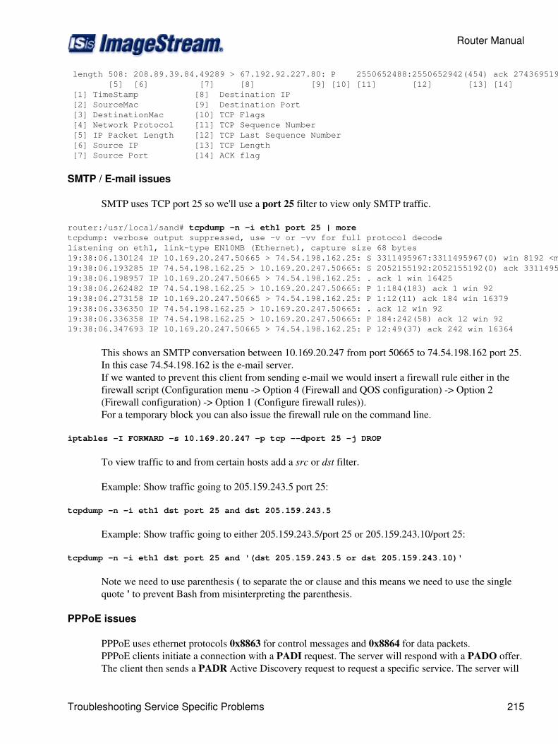
length 508: 208.89.39.84.49289 > 67.192.92.227.80: P 2550652488:2550652942(454) ack 2743695195 win 16560 [5] [6] [7] [8] [9] [10] [11] [12] [13] [14] [1] TimeStamp [8] Destination IP [2] SourceMac [9] Destination Port [3] DestinationMac [10] TCP Flags [4] Network Protocol [11] TCP Sequence Number [5] IP Packet Length [12] TCP Last Sequence Number [6] Source IP [13] TCP Length [7] Source Port [14] ACK flag
SMTP / E-mail issues
SMTP uses TCP port 25 so we'll use a port 25 filter to view only SMTP traffic.
router:/usr/local/sand# tcpdump -n -i eth1 port 25 | moretcpdump: verbose output suppressed, use -v or -vv for full protocol decodelistening on eth1, link-type EN10MB (Ethernet), capture size 68 bytes19:38:06.130124 IP 10.169.20.247.50665 > 74.54.198.162.25: S 3311495967:3311495967(0) win 8192 <mss 1460,nop,wscale 2,nop,nop,sackOK>19:38:06.193285 IP 74.54.198.162.25 > 10.169.20.247.50665: S 2052155192:2052155192(0) ack 3311495968 win 5840 <mss 1460,nop,wscale 6>19:38:06.198957 IP 10.169.20.247.50665 > 74.54.198.162.25: . ack 1 win 1642519:38:06.262482 IP 74.54.198.162.25 > 10.169.20.247.50665: P 1:184(183) ack 1 win 9219:38:06.273158 IP 10.169.20.247.50665 > 74.54.198.162.25: P 1:12(11) ack 184 win 1637919:38:06.336350 IP 74.54.198.162.25 > 10.169.20.247.50665: . ack 12 win 9219:38:06.336358 IP 74.54.198.162.25 > 10.169.20.247.50665: P 184:242(58) ack 12 win 9219:38:06.347693 IP 10.169.20.247.50665 > 74.54.198.162.25: P 12:49(37) ack 242 win 16364
This shows an SMTP conversation between 10.169.20.247 from port 50665 to 74.54.198.162 port 25.In this case 74.54.198.162 is the e-mail server.If we wanted to prevent this client from sending e-mail we would insert a firewall rule either in thefirewall script (Configuration menu -> Option 4 (Firewall and QOS configuration) -> Option 2(Firewall configuration) -> Option 1 (Configure firewall rules)).For a temporary block you can also issue the firewall rule on the command line.
iptables -I FORWARD -s 10.169.20.247 -p tcp --dport 25 -j DROP
To view traffic to and from certain hosts add a src or dst filter.
Example: Show traffic going to 205.159.243.5 port 25:
tcpdump -n -i eth1 dst port 25 and dst 205.159.243.5
Example: Show traffic going to either 205.159.243.5/port 25 or 205.159.243.10/port 25:
tcpdump -n -i eth1 dst port 25 and '(dst 205.159.243.5 or dst 205.159.243.10)'
Note we need to use parenthesis ( to separate the or clause and this means we need to use the singlequote ' to prevent Bash from misinterpreting the parenthesis.
PPPoE issues
PPPoE uses ethernet protocols 0x8863 for control messages and 0x8864 for data packets.PPPoE clients initiate a connection with a PADI request. The server will respond with a PADO offer.The client then sends a PADR Active Discovery request to request a specific service. The server will
Router Manual
Troubleshooting Service Specific Problems 215
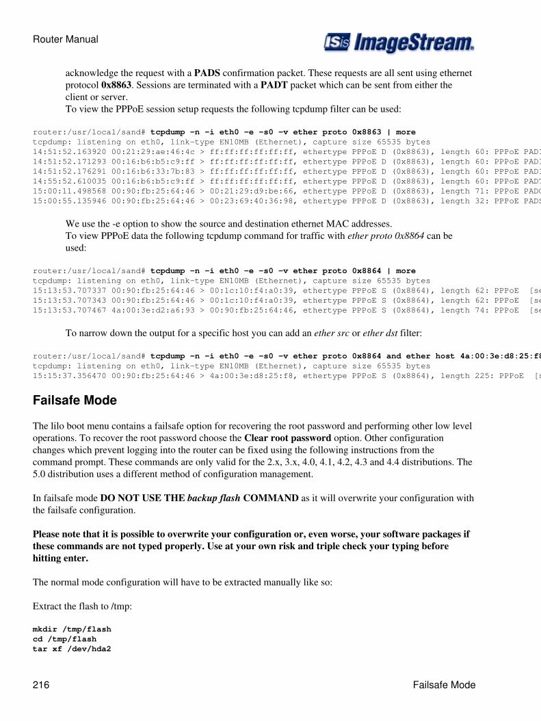
acknowledge the request with a PADS confirmation packet. These requests are all sent using ethernetprotocol 0x8863. Sessions are terminated with a PADT packet which can be sent from either theclient or server.To view the PPPoE session setup requests the following tcpdump filter can be used:
router:/usr/local/sand# tcpdump -n -i eth0 -e -s0 -v ether proto 0x8863 | moretcpdump: listening on eth0, link-type EN10MB (Ethernet), capture size 65535 bytes14:51:52.163920 00:21:29:ae:46:4c > ff:ff:ff:ff:ff:ff, ethertype PPPoE D (0x8863), length 60: PPPoE PADI [Host-Uniq 0x00000210] [Service-Name]14:51:52.171293 00:16:b6:b5:c9:ff > ff:ff:ff:ff:ff:ff, ethertype PPPoE D (0x8863), length 60: PPPoE PADI [Host-Uniq 0x909A0110] [Service-Name]14:51:52.176291 00:16:b6:33:7b:83 > ff:ff:ff:ff:ff:ff, ethertype PPPoE D (0x8863), length 60: PPPoE PADI [Host-Uniq 0x00000001] [Service-Name]14:55:52.610035 00:16:b6:b5:c9:ff > ff:ff:ff:ff:ff:ff, ethertype PPPoE D (0x8863), length 60: PPPoE PADT [Host-Uniq 0x909A0110] [Service-Name]15:00:11.498568 00:90:fb:25:64:46 > 00:21:29:d9:be:66, ethertype PPPoE D (0x8863), length 71: PPPoE PADO [AC-Name "ImageStream"] [Service-Name] [AC-Cookie 0x1896169478790F590269141FF1AC78B5BF030000] [Host-Uniq 0x509F4700]15:00:55.135946 00:90:fb:25:64:46 > 00:23:69:40:36:98, ethertype PPPoE D (0x8863), length 32: PPPoE PADS [ses 0x236] [Service-Name] [Host-Uniq 0xDB470000]
We use the -e option to show the source and destination ethernet MAC addresses.To view PPPoE data the following tcpdump command for traffic with ether proto 0x8864 can beused:
router:/usr/local/sand# tcpdump -n -i eth0 -e -s0 -v ether proto 0x8864 | moretcpdump: listening on eth0, link-type EN10MB (Ethernet), capture size 65535 bytes15:13:53.707337 00:90:fb:25:64:46 > 00:1c:10:f4:a0:39, ethertype PPPoE S (0x8864), length 62: PPPoE [ses 0x4c1] IP (0x0021), length 42: (tos 0x0, ttl 51, id 31409, offset 0, flags [DF], proto: TCP (6), length: 40) 38.116.147.180.80 > 208.89.38.15.4329: ., cksum 0x247c (correct), ack 2944659365 win 6553515:13:53.707343 00:90:fb:25:64:46 > 00:1c:10:f4:a0:39, ethertype PPPoE S (0x8864), length 62: PPPoE [ses 0x4c1] IP (0x0021), length 42: (tos 0x0, ttl 51, id 31410, offset 0, flags [DF], proto: TCP (6), length: 40) 38.116.147.180.80 > 208.89.38.15.4329: ., cksum 0x1fbc (correct), ack 1217 win 6553515:13:53.707467 4a:00:3e:d2:a6:93 > 00:90:fb:25:64:46, ethertype PPPoE S (0x8864), length 74: PPPoE [ses 0x169] IP (0x0021), length 54: (tos 0x0, ttl 63, id 22162, offset 0, flags [DF], proto: TCP (6), length: 52) 208.89.37.49.33586 > 208.111.145.179.80: ., cksum 0xb81d (correct), ack 935292310 win 65535 <nop,nop,timestamp 751697 2268923799>
To narrow down the output for a specific host you can add an ether src or ether dst filter:
router:/usr/local/sand# tcpdump -n -i eth0 -e -s0 -v ether proto 0x8864 and ether host 4a:00:3e:d8:25:f8 | moretcpdump: listening on eth0, link-type EN10MB (Ethernet), capture size 65535 bytes15:15:37.356470 00:90:fb:25:64:46 > 4a:00:3e:d8:25:f8, ethertype PPPoE S (0x8864), length 225: PPPoE [ses 0x6c] IP (0x0021), length 205: (tos 0x0, ttl 125, id 3573, offset 0, flags [DF], proto: TCP (6), length: 203) 207.114.197.99.443 > 74.116.44.166.58044: P, cksum 0x1198 (correct), 863428291:863428454(163) ack 1873881143 win 65535
Failsafe Mode
The lilo boot menu contains a failsafe option for recovering the root password and performing other low leveloperations. To recover the root password choose the Clear root password option. Other configurationchanges which prevent logging into the router can be fixed using the following instructions from thecommand prompt. These commands are only valid for the 2.x, 3.x, 4.0, 4.1, 4.2, 4.3 and 4.4 distributions. The5.0 distribution uses a different method of configuration management.
In failsafe mode DO NOT USE THE backup flash COMMAND as it will overwrite your configuration withthe failsafe configuration.
Please note that it is possible to overwrite your configuration or, even worse, your software packages ifthese commands are not typed properly. Use at your own risk and triple check your typing beforehitting enter.
The normal mode configuration will have to be extracted manually like so:
Extract the flash to /tmp:
mkdir /tmp/flashcd /tmp/flashtar xf /dev/hda2
Router Manual
216 Failsafe Mode
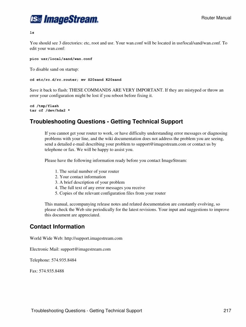
ls
You should see 3 directories: etc, root and usr. Your wan.conf will be located in usr/local/sand/wan.conf. Toedit your wan.conf:
pico usr/local/sand/wan.conf
To disable sand on startup:
cd etc/rc.d/rc.router; mv S20sand K20sand
Save it back to flash: THESE COMMANDS ARE VERY IMPORTANT. If they are mistyped or throw anerror your configuration might be lost if you reboot before fixing it.
cd /tmp/flashtar cf /dev/hda2 *
Troubleshooting Questions - Getting Technical Support
If you cannot get your router to work, or have difficulty understanding error messages or diagnosingproblems with your line, and the wiki documentation does not address the problem you are seeing,send a detailed e-mail describing your problem to [email protected] or contact us bytelephone or fax. We will be happy to assist you.
Please have the following information ready before you contact ImageStream:
The serial number of your router1. Your contact information2. A brief description of your problem3. The full text of any error messages you receive4. Copies of the relevant configuration files from your router5.
This manual, accompanying release notes and related documentation are constantly evolving, soplease check the Web site periodically for the latest revisions. Your input and suggestions to improvethis document are appreciated.
Contact Information
World Wide Web: http://support.imagestream.com
Electronic Mail: [email protected]
Telephone: 574.935.8484
Fax: 574.935.8488
Router Manual
Troubleshooting Questions - Getting Technical Support 217
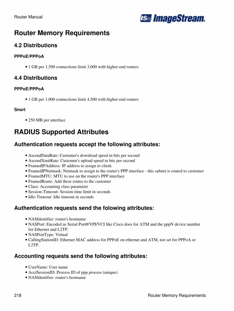
Router Memory Requirements
4.2 Distributions
PPPoE/PPPoA
1 GB per 1,500 connections limit 3,000 with higher-end routers•
4.4 Distributions
PPPoE/PPPoA
1 GB per 1,000 connections limit 4,500 with higher-end routers•
Snort
250 MB per interface•
RADIUS Supported Attributes
Authentication requests accept the following attributes:
AscendDataRate: Customer's download speed in bits per second• AscendXmitRate: Customer's upload speed in bits per second• FramedIPAddress: IP address to assign to client.• FramedIPNetmask: Netmask to assign to the router's PPP interface - this subnet is routed to customer• FramedMTU: MTU to use on the router's PPP interface• FramedRoute: Add these routes to the customer• Class: Accounting class parameter• Session-Timeout: Session time limit in seconds• Idle-Timeout: Idle timeout in seconds•
Authentication requests send the folowing attributes:
NASIdentifier: router's hostname• NASPort: Encoded as Serial Port#/VPI/VCI like Cisco does for ATM and the pppN device numberfor Ethernet and L2TP.
•
NASPortType: Virtual• CallingStationID: Ethernet MAC address for PPPoE on ethernet and ATM, not set for PPPoA orL2TP.
•
Accounting requests send the following attributes:
UserName: User name• AcctSessionID: Process ID of ppp process (unique)• NASIdentifier: router's hostname•
Router Manual
218 Router Memory Requirements
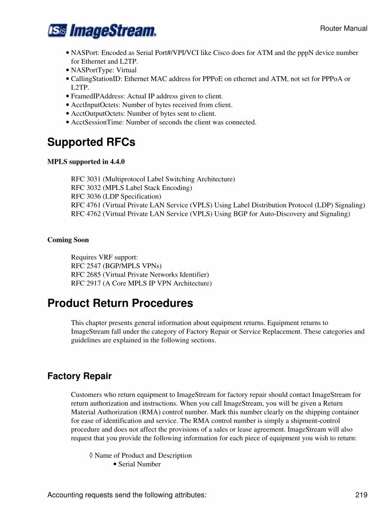
NASPort: Encoded as Serial Port#/VPI/VCI like Cisco does for ATM and the pppN device numberfor Ethernet and L2TP.
•
NASPortType: Virtual• CallingStationID: Ethernet MAC address for PPPoE on ethernet and ATM, not set for PPPoA orL2TP.
•
FramedIPAddress: Actual IP address given to client.• AcctInputOctets: Number of bytes received from client.• AcctOutputOctets: Number of bytes sent to client.• AcctSessionTime: Number of seconds the client was connected.•
Supported RFCs
MPLS supported in 4.4.0
RFC 3031 (Multiprotocol Label Switching Architecture)RFC 3032 (MPLS Label Stack Encoding)RFC 3036 (LDP Specification)RFC 4761 (Virtual Private LAN Service (VPLS) Using Label Distribution Protocol (LDP) Signaling)RFC 4762 (Virtual Private LAN Service (VPLS) Using BGP for Auto-Discovery and Signaling)
Coming Soon
Requires VRF support:RFC 2547 (BGP/MPLS VPNs)RFC 2685 (Virtual Private Networks Identifier)RFC 2917 (A Core MPLS IP VPN Architecture)
Product Return Procedures
This chapter presents general information about equipment returns. Equipment returns toImageStream fall under the category of Factory Repair or Service Replacement. These categories andguidelines are explained in the following sections.
Factory Repair
Customers who return equipment to ImageStream for factory repair should contact ImageStream forreturn authorization and instructions. When you call ImageStream, you will be given a ReturnMaterial Authorization (RMA) control number. Mark this number clearly on the shipping containerfor ease of identification and service. The RMA control number is simply a shipment-controlprocedure and does not affect the provisions of a sales or lease agreement. ImageStream will alsorequest that you provide the following information for each piece of equipment you wish to return:
Name of Product and Description◊ Serial Number•
Router Manual
Accounting requests send the following attributes: 219
Customer Order Number• Failure Symptoms•
You will be provided a shipping address to return any defective equipment or parts.
Re-packing Guidelines For Equipment Return
Equipment or parts that are being returned to ImageStream for any reason must be properly packagedto prevent damage in shipment and handling. If the original packing material and shipping containerare available, reuse these items to return equipment. If these items are not available, package theequipment for shipment as follows:
Secure movable and exposed parts before shipping so will not become loose in shipment andcause damage or be damaged.
◊
Abrasive or dusty materials should not be used for cushioning.◊ Customers should attempt to ship equipment weighing more than 20 pounds in sturdy ordouble-wall containers.
◊
When returning more than one item in the same shipping container, wrap each unit individually inair-cell or similar material, prevent possibility of movement of individual units during shipment. Placeeach printed circuit (PC) card in an individual conductive bag, wrap the card in a double layer air-cellor similar material if possible. Ship in a sturdy container that prevents movement of individuallywrapped cards.
Note: Return shipments are your responsibility. You will be responsible for any damages caused byimproper packaging.
Specific Packing Guidelines
In returning equipment to ImageStream, the alternative packaging guidelines are listed with theexception of procedures authorized by ImageStream.
Most Desirable
Return the equipment in its original packing material and shipping container.
Acceptable
Wrap the equipment in sufficient air-cell (bubble pack) or similar material providing cushioning, shipin a double-wall container if possible.
Helpful Tools
This chapter presents some helpful tools for use in configuring and troubleshooting your ImageStreamRouter.
Router Manual
220 Factory Repair
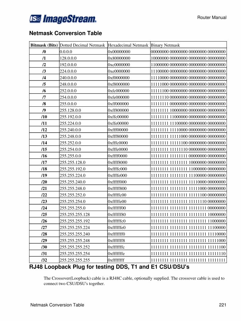
Netmask Conversion Table
Bitmask (Bits) Dotted Decimal Netmask Hexadecimal Netmask Binary Netmask/0 0.0.0.0 0x00000000 00000000 00000000 00000000 00000000/1 128.0.0.0 0x80000000 10000000 00000000 00000000 00000000/2 192.0.0.0 0xc0000000 11000000 00000000 00000000 00000000/3 224.0.0.0 0xe0000000 11100000 00000000 00000000 00000000/4 240.0.0.0 0xf0000000 11110000 00000000 00000000 00000000/5 248.0.0.0 0xf8000000 11111000 00000000 00000000 00000000/6 252.0.0.0 0xfc000000 11111100 00000000 00000000 00000000/7 254.0.0.0 0xfe000000 11111110 00000000 00000000 00000000/8 255.0.0.0 0xff000000 11111111 00000000 00000000 00000000/9 255.128.0.0 0xff800000 11111111 10000000 00000000 00000000/10 255.192.0.0 0xffc00000 11111111 11000000 00000000 00000000/11 255.224.0.0 0xffe00000 11111111 11100000 00000000 00000000/12 255.240.0.0 0xfff00000 11111111 11110000 00000000 00000000/13 255.248.0.0 0xfff80000 11111111 11111000 00000000 00000000/14 255.252.0.0 0xfffc0000 11111111 11111100 00000000 00000000/15 255.254.0.0 0xfffe0000 11111111 11111110 00000000 00000000/16 255.255.0.0 0xffff0000 11111111 11111111 00000000 00000000/17 255.255.128.0 0xffff8000 11111111 11111111 10000000 00000000/18 255.255.192.0 0xffffc000 11111111 11111111 11000000 00000000/19 255.255.224.0 0xffffe000 11111111 11111111 11100000 00000000/20 255.255.240.0 0xfffff000 11111111 11111111 11110000 00000000/21 255.255.248.0 0xfffff800 11111111 11111111 11111000 00000000/22 255.255.252.0 0xfffffc00 11111111 11111111 11111100 00000000/23 255.255.254.0 0xfffffe00 11111111 11111111 11111110 00000000/24 255.255.255.0 0xffffff00 11111111 11111111 11111111 00000000/25 255.255.255.128 0xffffff80 11111111 11111111 11111111 10000000/26 255.255.255.192 0xffffffc0 11111111 11111111 11111111 11000000/27 255.255.255.224 0xffffffe0 11111111 11111111 11111111 11100000/28 255.255.255.240 0xfffffff0 11111111 11111111 11111111 11110000/29 255.255.255.248 0xfffffff8 11111111 11111111 11111111 11111000/30 255.255.255.252 0xfffffffc 11111111 11111111 11111111 11111100/31 255.255.255.254 0xfffffffe 11111111 11111111 11111111 11111110/32 255.255.255.255 0xffffffff 11111111 11111111 11111111 11111111
RJ48 Loopback Plug for testing DDS, T1 and E1 CSU/DSU's
The Crossover(Loopback) cable is a RJ48C cable, optionally supplied. The crossover cable is used toconnect two CSU/DSU's together.
Router Manual
Netmask Conversion Table 221
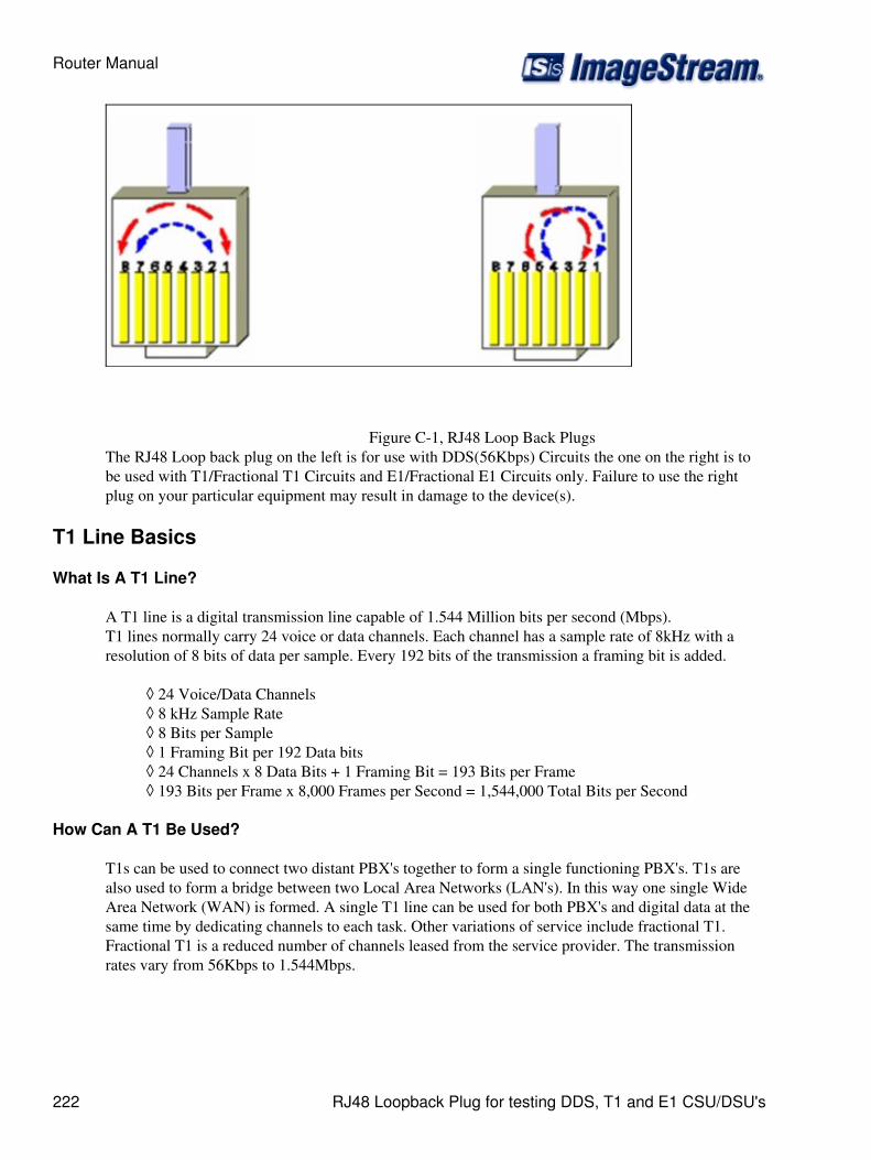
Figure C-1, RJ48 Loop Back PlugsThe RJ48 Loop back plug on the left is for use with DDS(56Kbps) Circuits the one on the right is tobe used with T1/Fractional T1 Circuits and E1/Fractional E1 Circuits only. Failure to use the rightplug on your particular equipment may result in damage to the device(s).
T1 Line Basics
What Is A T1 Line?
A T1 line is a digital transmission line capable of 1.544 Million bits per second (Mbps).T1 lines normally carry 24 voice or data channels. Each channel has a sample rate of 8kHz with aresolution of 8 bits of data per sample. Every 192 bits of the transmission a framing bit is added.
24 Voice/Data Channels◊ 8 kHz Sample Rate◊ 8 Bits per Sample◊ 1 Framing Bit per 192 Data bits◊ 24 Channels x 8 Data Bits + 1 Framing Bit = 193 Bits per Frame◊ 193 Bits per Frame x 8,000 Frames per Second = 1,544,000 Total Bits per Second◊
How Can A T1 Be Used?
T1s can be used to connect two distant PBX's together to form a single functioning PBX's. T1s arealso used to form a bridge between two Local Area Networks (LAN's). In this way one single WideArea Network (WAN) is formed. A single T1 line can be used for both PBX's and digital data at thesame time by dedicating channels to each task. Other variations of service include fractional T1.Fractional T1 is a reduced number of channels leased from the service provider. The transmissionrates vary from 56Kbps to 1.544Mbps.
Router Manual
222 RJ48 Loopback Plug for testing DDS, T1 and E1 CSU/DSU's
What is a CSU/DSU?
A Channel Service Unit (CSU)/Data Service Unit (DSU) is a device used to terminate a digital servicesuch as a T1 or E1. The CSU/DSU maintains records on different types of line errors and providesfunctions for line conditioning, line equalization, and loopback modes. These functions can beaccessed from the main office of the service provider to maintain line quality.
What Needs to be Configured for a CSU to Work?
The T1 service provider will inform the customer what settings should be set for their specific service.The service provider will specify the line build out (LBO= 0, -7.5, -15 dB), framing type (D4 or ESF),network line code (B8ZS or AMI), pulse density enforcing (AMI only), and the signaling mode(ATT54016 or ANSI T1.403) used to configure the CSU. For a fractional T1, the service providermust also specify the active channels (DS0s).
AMI Versus B8ZS Line Coding
When using AMI (alternate mark inversion) mode with non-inverted data, a problem arises when aseries of zeros is sent across the transmission line. These zeros prevent the receiver, who relies onclock edges for sync, from establishing a proper sync. There are two ways to correct this problem.
1. AMI Mode with Inverted HDLC Data
If the network (external CSU, carrier, etc.) can AMI mode with inverted HDLC data, theN2csu can be placed in INVERT HDLC DATA mode. With data inversion enabled, properones density will be maintained on the line.
2. B8ZS Mode (If Available)
B8ZS (bipolar with 8-zero substitution) mode was designed to correct for AMI's pulse densityproblem. B8ZS inserts BPVs at specific points in the data to allow the receiver to maintainsync. At the receiving end, any B8ZS BPV patterns are recognized and the correct datapatterns are re-constructed.
Packet flow inside the Linux Kernel
PacketFlow.png
Basic Networking
Introduction
This page describes general network concepts that you must understand before you configure yourImageStream router. See the glossary linked to our Other Resources page for unfamiliar terms.
Router Manual
T1 Line Basics 223

Domain Name Server (DNS)
The Domain Name Server (DNS) can be thought of as an interpreter. Humans can remember wordsbetter than long strings of numbers. When the Internet was developed, there was a need to mergepeople's natural ability to remember words with the computer's ability to understand numbers or bits,which is a series of ones and zeros. The DNS server translates a Web address such ashttp://www.imagestream.com to an IP address of 205.159.243.5. Every time you direct an internetsearch or enter a Web address, the DNS server is called to translate the address into an IP address thatthe computer can recognize and use. Without the DNS server, the Internet would not exist as it doestoday.
Network Addressing
ImageStream routers support packet routing using the IP protocol. The Internet Protocol (IP) is apacket-based protocol used to exchange data over computer networks. IP provides addressing andcontrol information that allows data packets to be routed across networks.
IP Addressing
IP address descriptions are found in RFC 1166, Internet Numbers. The Network Working Groupmaintains and distributes the RFC documents. The American Registry for Internet Numbers (ARIN)assigns IP addresses and network numbers to Internet service providers (ISPs), who in turn provide totheir customers a range of addresses appropriate to the number of host devices on their network. Thesections that follow describe the various types of IP addresses, how addresses are given, and routingissues related to IP.
IP Address Notation
IP addresses are written in dotted decimal notation consisting of four numbers separated by dots(periods). Each number, written in decimal, represents an 8-bit octet (sometimes informally referredto as a byte) giving each number a range of 0 through 255, inclusive. When strung together, the fouroctets form the 32-bit IP address. Table 1 shows 32-bit values expressed as IP addresses. The largestpossible value of a field in dotted decimal notation is 255, which represents an octet where all the bitsare 1s.
IP Address Classes
IP addresses are generally divided into different classes of addresses based on the number of hosts andsubnetworks required to support the hosts. As described in RFC 1166, IP addresses are 32-bitquantities divided into five classes. Each class has a different number of bits allocated to the networkand host portions of the address. For this discussion, consider a network to be a collection ofcomputers (hosts) that have the same network field values in their IP addresses. The concept ofclasses is being made obsolete by classless interdomain routing (CIDR).
Instead of dividing networks by class, CIDR groups them into address ranges. A network rangeconsists of an IP address prefix and a netmask length. The address prefix specifies the high-order bitsof the IP network address. The netmask length specifies the number of high-order bits in the prefix
Router Manual
224 Domain Name Server (DNS)

that an IP address must match to fall within the range indicated by the prefix.
For example, 192.168.42.x describes a Class C network with addresses ranging from 192.168.42.0through 192.168.42.255. CIDR uses 192.168.42.0/24 to describe the same range of addresses. RIPversion 1 is an example of a protocol that uses address classes. OSPF and BGP-4 are examples ofprotocols that do not use address classes.
32-Bit Value Dotted Decimal Notation01100100.01100100.01100100.00001010 100.100.100.1011000011.00100000.00000100.11001000 195.32.4.200
Table 1 - IP Address NotationClass A Addresses
The class A IP address format allocates the highest 8 bits to the network field and sets thehighest-priority bit to 0 (zero). The remaining 24 bits form the host field. Only 126 class A networkscan exist (0 is reserved, and 127 is used for loopback networks), but each class A network can havealmost 17 million hosts. No new class A networks can be assigned at this time.
For example:
10.100.232.1 __ _________ / \ / \ Network \ address Host address
Class B Addresses
The class B IP address format allocates the highest 16 bits to the network field and sets the twohighest-order bits to 1 and 0, providing a range from 128 through 191, inclusive. The remaining 16bits form the host field. More than 16,000 class B networks can exist, and each class B network canhave up to 65,534 hosts.
For example:
10.10.232.201 _____ _______ / \ / \ Network \ address Host address
Class C Addresses
The class C IP address format allocates the highest 24 bits to the network field and sets the threehighest-order bits to 1, 1, and 0, providing a range from 192 through 223, inclusive. The remaining 8bits form the host field. More than two million class C networks can exist, and each class C networkcan have up to 254 hosts.
Router Manual
IP Address Classes 225
For example:
10.10.12.121 ________ ___ / \ / \ Network \ address Host address
Class D Addresses
The class D IP address format was designed for multicast groups, as discussed in RFC 988. In class Daddresses, the 4 highest-order bits are set to 1, 1, 1, and 0, providing a range from 224 through 239,inclusive. Class D addresses are currently used primarily for the multicast backbone (MBONE) of theInternet.
Class E Addresses
The class E IP address is reserved for future use. In class E addresses, the 4 highest-order bits are setto 1, 1, 1, and 1. Routers currently ignore class E IP addresses.
Reserved IP Addresses
Some IP addresses are reserved for special uses and cannot be used for host addresses. Table 2 listsranges of IP addresses and shows which addresses are reserved, which are available to be assigned,and which are for broadcast.
Class IP Address StatusA 0.0.0.0 Reserved
1.0.0.0 through 126.0.0.0 Available127.0.0.0 Reserved
B 128.0.0.0 Reserved128.1.0.0 through 191.254.255.255 Available191.255.0.0 Reserved
C 192.0.0.0 Reserved192.0.1.0 through 223.255.254.255 Available223.255.255.0 Reserved
D 224.0.0.0 through 239.255.255.255 Multicast group addressesE 240.0.0.0 through 255.255.255.254 Reversed
255.255.255.255 Broadcast
Table 2 - Reserved and Available IP AddressesPrivate IP Networks
RFC 1597 reserves three IP network addresses for private networks. The addresses 10.0.0.0/8,192.168.0.0/16, and 172.16.0.0/20 can be used by anyone for setting up their own internal IPnetworks.
Router Manual
226 IP Address Classes
IP Address Conventions
If the bits in the host portion of an address are all 0, that address refers to the network specified in thenetwork portion of the address. For example, the class C address 192.31.7.0 refers to a particularnetwork. Historically, this address was used as a broadcast.
The standard for broadcast is high, which uses all 1s in the host portion (for example, 192.168.1.255);however, many networks still use all 0s. The ImageStream router can be configured either way andshould be set to match the other systems on your network. Note: Do not assign an IP address with all0s or all 1s in the host portion of the address to a host on the network, because these are reserved asbroadcast addresses. With CIDR, networks are specified with an IP prefix and netmask length--forexample, 172.16.0.0/16, 192.168.1.0/24, or 192.168.200.240/28.
Netmasks
A netmask is a four-octet number that identifies either a supernetwork (supernet) or a subnetwork(subnet). A netmask that designates a subnet is called a subnet mask.
Using Subnet Masks to Create IP Subnets
Subnet masks are used to divide networks into smaller, more manageable groups of hosts known assubnets. Subnetting is a scheme for imposing a hierarchy on hosts on a single physical network. Theusual practice is to use the first few bits in the host portion of the network address for a subnet field.RFC 950, Internet Standard Subnetting Procedure, describes subnetting.
A subnet mask identifies the subnet field of a network address. This mask is a 32-bit number writtenin dotted decimal notation with all 1s (ones) in the network and subnet portions of the address, and all0s (zeros) in the host portion. This scheme allows for the identification of the host portion of anyaddress on the network. Table 3 shows the subnet masks you can use to divide a class C network intosubnets.
Length (SubnetBits)
Number ofSubnets
Number of Hosts perSubnet
Hexadecimal SubnetMask
Dotted Decimal SubnetMask
24 1 254 0xffffff00 255.255.255.025 2 126 0xffffff80 255.255.255.12826 4 62 0xffffffc0 255.255.255.19227 8 30 0xffffffe0 255.255.255.22428 16 14 0xfffffff0 255.255.255.24029 32 6 0xfffffff8 255.255.255.24830 64 2 0xfffffffc 255.255.255.25232 256 1 0xffffffff 255.255.255.255
Table 3 - Subnet Masks for a Class C Network
Router Manual
Private IP Networks 227
Understanding the Network Interface Configuration File (wan.conf)
wan.conf is the primary configuration file used by ImageStream's Inetics driver componentarchitecture and the management utility configmgr. configmgr uses the wan.conf file to manage theconfiguration of all Inetics interfaces. See the Command Reference for more information oncommands supported by configmgr and Inetics.
The default wan.conf file is:
! version 2.00 ! interface Ethernet0 ip address 10.10.199.199 255.0.0.0 ! interface Serial0 shutdown description Port 0 encapsulation hdlc ip address 192.168.10.1 255.255.255.252 ! # Set the default route via Serial0 using the device #ip route add 0.0.0.0/0 dev Serial0 # Set the default route via Serial0 using an IP #ip route add default via 192.168.10.2 ! end
The values in the default file are explained below.
version 2.00 - Denotes the version number of the configuration file and driver set. This value is set byImageStream and should not be changed or modified.
interface Ethernet0 - Denotes the start of the configuration section for the first Ethernet device inyour system. All commands that follow this line until the next ! mark will be applied to Ethernet0.
ip address 10.10.199.199 255.0.0.0 - Specifies the IP address and netmask for Ethernet0.
!, end - Signifies the end of a configuration section or the end of the wan.conf file. You must includea "!" to delimit each section of the configuration file and an "end" statement at the end of the file.
interface Serial0 - Denotes the start of the configuration section for the first Serial port in yoursystem. All commands that follow this line until the next ! mark will be applied to Serial0.
shutdown - Instructs the router not to start this port when Inetics is started or reloaded.
description Port 0 - Sets a description for this device. The description is optional used for reportingpurposes in other utilities. Setting a value here does not affect the operation of the port.
encapsulation hdlc - Specifies the Cisco HDLC protocol for this serial port.
ip address 192.168.10.1 255.255.255.252 - Specifies the IP address and netmask for Serial0.
Router Manual
228 Understanding the Network Interface Configuration File (wan.conf)
# Set the default route via Serial0 using the device - A comment inserted in the configuration file.Lines that begin with # or "!" are ignored by Inetics when starting or reloading configurations.
#ip route add 0.0.0.0/0 dev Serial0 - A route statement setting the default route to the Serial0 device.Note that this command is commented out, so it will be ignored by Inetics.
#ip route add default via 192.168.10.2 - A route statement setting the default route to the IP addressof 192.168.10.2. Note that this command is commented out, so it will be ignored by Inetics. Thiscommand also uses the alternate default route designator of default instead of the numeric 0.0.0.0/0.The designators are equivalent.
Understanding WAN's
The following section describes the basic WAN's implementation and operation.
WAN ports are used for high-speed dedicated connections between two local area networks (LANs).Once a connection is established between two sites, a wide area network (WAN) is achieved. WANconnections can be achieved through the use of dedicated leased lines such as T1, E1 or higherbandwidth lines, SONET/SDH connections, ATM connections, Frame Relay connections, or ISDNlines. Connection rates can range from 9600bps to 2.048Mbps (E1) to 2.488Gbps (OC-48).ImageStream routers support these connection types using one or more serial ports with or withoutintegrated CSU/DSUs.
All WAN port connections are very similar and are represented in the diagram below.
Router Manual
Understanding WAN's 229
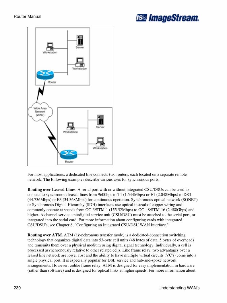
For most applications, a dedicated line connects two routers, each located on a separate remotenetwork. The following examples describe various uses for synchronous ports.
Routing over Leased Lines. A serial port with or without integrated CSU/DSUs can be used toconnect to synchronous leased lines from 9600bps to T1 (1.544Mbps) or E1 (2.048Mbps) to DS3(44.736Mbps) or E3 (34.368Mbps) for continuous operation. Synchronous optical network (SONET)or Synchronous Digital Hierarchy (SDH) interfaces use optical instead of copper wiring andcommonly operate at speeds from OC-3/STM-1 (155.52Mbps) to OC-48/STM-16 (2.488Gbps) andhigher. A channel service unit/digital service unit (CSU/DSU) must be attached to the serial port, orintegrated into the serial card. For more information about configuring cards with integratedCSU/DSU's, see Chapter 8, "Configuring an Integrated CSU/DSU WAN Interface."
Routing over ATM. ATM (asynchronous transfer mode) is a dedicated-connection switchingtechnology that organizes digital data into 53-byte cell units (48 bytes of data, 5 bytes of overhead)and transmits them over a physical medium using digital signal technology. Individually, a cell isprocessed asynchronously relative to other related cells. Like frame relay, two advantages over aleased line network are lower cost and the ability to have multiple virtual circuits (VC's) come into asingle physical port. It is especially popular for DSL service and hub-and-spoke networkarrangements. However, unlike frame relay, ATM is designed for easy implementation in hardware(rather than software) and is designed for optical links at higher speeds. For more information about
Router Manual
230 Understanding WAN's
configuring ATM, see Chapter 9, "Configuring an ATM Interface."
Routing over Frame Relay. Frame Relay provides connectivity using a packet switched network. Itstwo advantages over a leased line network are lower cost and the ability to have multiple permanentvirtual circuits (PVC's) come into a single physical port. It is especially popular for hub-and-spokenetwork arrangements. For example, a dozen field offices with T1 or fractional T1 Frame Relayconnections can connect to a central office using a single DS3, fractional DS3 or T1 Frame Relayconnection. The central office requires only one CSU/DSU and serial port on the router, instead oftwelve. For more information about configuring frame relay, see Chapter 10, "Configuring a FrameRelay Interface."
Routing over ISDN. Integrated Services Digital Network (ISDN) provides fast dial-up connectivityfor applications where the expense of a dedicated Frame Relay, ATM or leased line connection is notappropriate for the amount and nature of the traffic. For more information about ISDN Basic RateInterface (BRI) connections, see Chapter 11, "Configuring an ISDN BRI Interface."
Glossary
Asymmetric Digital Subscriber Line (ADSL) - form of DSL, a data communications technology thatenables faster data transmission over copper telephone lines than a conventional voiceband modem canprovide. This is accomplished by utilizing frequencies that are not used by a voice telephone call. A splitter ormicro filters allow a single telephone connection to be used for both ADSL service and voice calls at the sametime. However, this technology is not perferred if the distances exceed 5km (approx. 3 miles).
Asymmetric Digital Subscriber Line (ADSL2) - is an ITU (International Telecommunication Union)standard, also referred to as ADSL2 (and Seamless Rate Adaptation). It extends the capability of basic ADSLin data rates. The data rates can, in the best situation, be as high as 12 Mbit/s downstream and 3.5 Mbit/supstream depending on line quality. The distance from the DSLAM to the customer's equipment is usually themost significant factor in line quality.
Asymmetric Digital Subscriber Line (ADSL2+) - ADSL2+ is capable of doubling the frequency band oftypical ADSL connections from 1.1 MHz to 2.2 MHz. This doubles the downstream data rates of the previousADSL2 standard of up to 12 Mbit/s, but like the previous standards will degrade from its peak bitrate after acertain distance.
Asynchronous Transfer Mode (ATM) - cell relay, packet switching network and data link layer protocolwhich encodes data traffic into small (53 bytes; 48 bytes of data and 5 bytes of header information)fixed-sized cells. ATM provides data link layer services that run over SONET (Synchronous OpticalNetworking) Layer 1 links. This differs from other technologies based on packet-switched networks (such asthe Internet Protocol or Ethernet), in which variable sized packets (sometimes known as frames) are used.ATM is a connection-oriented technology, in which a logical connection is established between the twoendpoints before the actual data exchange begins.
Basic Input/Output System (BIOS) - The BIOS software is built into the equipment, and is the first code runby a unit when powered on ('boot firmware'). The primary function of the BIOS is to load and start anoperating system. When the unit starts up, the first job for the BIOS is to initialize and identify system devicessuch as the video display card, keyboard and mouse, hard disk, CD/DVD drive and other hardware. The BIOSthen locates software held on a peripheral device (designated as a 'boot device'), such as a hard disk or a CD,
Router Manual
Glossary 231
and loads and executes that software, giving it control of the PC
Border Gateway Protocol (BGP) - the core routing protocol of the Internet. It works by maintaining a tableof IP networks or 'prefixes' which designate network reachability among autonomous systems (AS). BGPmakes routing decisions based on path, network policies and/or rulesets.
Crypto IP Encapsulation (CIPE) - CIPE is a VPN implementation developed primarily for Linux. CIPE usesencrypted IP packets that are encapsulated, or "wrapped", in datagram (UDP) packets. Packets are givendestination header information and are encrypted using the default CIPE encryption mechanism, thentransferred over IP as UDP packets via its own virtual device (cipcbx) over a carrier network (such as theInternet) to an intended remote node.
CSU/DSU - For digital lines, a channel service unit (CSU) and a data service unit (DSU) are required. Thetwo are often combined into a single piece of equipment, called the CSU/DSU. The CSU provides terminationfor the digital signal and ensures connection integrity through error correction and line monitoring. The DSUconverts the T-carrier line frames into frames the LAN can interpret and vice versa. It also connects T-carrierlines with terminating equipment.
Data Link Connection Identifier (DLCI) - a channel number which is attached to frame relay data frames totell the network how to route the data. A 10-bit field that defines the destination address of a packet. Theaddress is local on a link-by-link basis.
Differentiated Services(DIFFServ) - a computer networking architecture that specifies a simple, scalable andcoarse-grained mechanism for classifying, managing network traffic and providing quality of service (QoS)guarantees on modern IP networks.
Digital Signal 3 (DS3) - is a digital signal level 3 T-carrier. It may also be referred to as a T3 line.
Dynamic Routing - Routing algorithms designed to adjust to changing network circumstances by analyzingincoming routing update messages. If the message indicates that a network change has occurred, the routingsoftware recalculates routes and sends out new routing update messages. These messages permeate thenetwork, stimulating routers to rerun their algorithms and change their routing tables accordingly.
Dynamic Host Configuration Protocol (DHCP) - a set of rules used by communications devices such as acomputer, router or network adapter to allow the device to requestand obtain an IP address from a serverwhich has a list of addresses available for assignment.
E1 - E1 circuits are very common in most telephone exchanges and are used to connect to medium and largecompanies, to remote exchanges and in many cases between exchanges. E3 lines are used between exchanges,operators and/or countries, and have a transmission speed of 34.368 Mbit/s.
Firewall - a hardware or software device which is configured to permit, deny, or proxy data through acomputer network which has different levels of trust. Standard security practices dictate a "default-deny"firewall ruleset, in which the only network connections which are allowed are the ones that have beenexplicitly allowed.
Frame Relay - consists of an efficient data transmission technique used to send digital information quicklyand cheaply in a relay of frames to one or many destinations from one or many end-points. Network providers
Router Manual
232 Glossary
commonly implement frame relay for voice and data as an encapsulation technique, used between local areanetworks (LANs) over a wide area network (WAN). Each end-user gets a private line (or leased line) to aframe-relay node. The frame-relay network handles the transmission over a frequently-changing pathtransparent to all end-users.
Fully Qualified Domain Name (FQDN) - consists of a host and domain name, including top-level domain.For example, www.ImageStream.com is a fully qualified domain name. www is the host, ImageStream is thesecond-level domain, and.com is the top level domain.
High-Level Data Link Control (HDLC) - is now the basis for the framing mechanism used with thePoint-to-Point Protocol on synchronous lines, as used by many servers to connect to a wide area network,most commonly the Internet. A mildly different version is also used as the control channel for E-carrier (E1)and SONET multichannel telephone lines.
ip address - An IP address (Internet Protocol address) is a unique address that certain electronic devices usein order to identify and communicate with each other on a computer network utilizing the Internet Protocolstandard (IP)-in simpler terms, a computer address. IP addresses are managed and created by the InternetAssigned Numbers Authority (IANA). The IANA generally allocates super-blocks to Regional InternetRegistries, who in turn allocate smaller blocks to Internet service providers and enterprises.
Integrated Services Digital Network (ISDN) - is a circuit-switched telephone network system, designed toallow digital transmission of voice and data over ordinary telephone copper wires, resulting in better qualityand higher speeds than that which is available with the PSTN system. More broadly, ISDN is a set ofprotocols for establishing and breaking circuit switched connections, and for advanced call features for theuser.
iptables - iptables are a standard part of all modern Linux distributions from which the system administratorcreates the rules for the packet filtering and NAT modules.
IP Tunnel - is the process of embedding one IP packet inside of another, for the purpose of simulating aphysical connection between two remote networks across an intermediate network. IP tunnels are often usedin conjunction with IPSec protocol to create a VPN between two or more remote networks across a "hostile"network such as the Internet.
International Telephone and Telegraph Consultative Committee (CCITT) - coordinates standards fortelecommunications on behalf of the International Telecommunication Union (ITU) and is based in Geneva,Switzerland.
Local Area Network (LAN) - a computer network covering a small geographic area, like a home, office, orgroup of buildings. The defining characteristics of LANs, in contrast to Wide area networks (WANs), includetheir much higher data transfer rates, smaller geographic range, and lack of a need for leasedtelecommunication lines.
Local Management Interface (LMI) - a signaling standard used between routers and frame relay switches.Communication takes place between a router and the first frame relay switch it's connected to. Informationabout keepalives, global addressing, IP Multicast and the status of virtual circuits is commonly exchangedusing LMI.
Router Manual
Glossary 233
Multilink PPP (MLPPP) - Multilink PPP can connect multiple links between two systems as needed toprovide extra bandwidth. Remotely accessing resources through PPP Multilink allows for the increase inoverall throughput by combining the bandwidth of two or more physical communication links such as analogmodems, ISDN, and other analog/digital links.
Network Address Translation (NAT) - also known as Network Masquerading, Native Address Translationor IP Masquerading) involves re-writing the source and/or destination addresses of IP packets as they passthrough a Router or firewall. Most systems using NAT do so in order to enable multiple hosts on a privatenetwork to access the Internet using a single public IP address (or gateway). Many network administratorsfind NAT a convenient technique and use it widely. Nonetheless, NAT can introduce complications incommunication between hosts and may impact performance.
Open Shortest Path First (OSPF) - protocol is a hierarchical interior gateway protocol (IGP) for routing inInternet Protocol, using a link-state in the individual areas that make up the hierarchy to determine the "bestpath" routes.
Open Systems Interconnection Basic Reference Model (OSI reference model) - a layered, abstractdescription for communications and computer network protocol design, developed as part of Open SystemsInterconnection (OSI) initiative. It is also called the OSI seven layer model. The layers, described below, are,from top to bottom, Application, Presentation, Session, Transport, Network, Data Link and Physical.Point-to-Point Protocol (PPP) - is commonly used to establish a direct connection between two nodes. Itcan connect computers using serial cable, phone line, trunk line, cellular telephone, specialized radiolinks, or fiber optic links. Most Internet service providers use PPP for customers' dial-up access to theInternet. Two common encapsulated forms of PPP are used in a similar role with Digital SubscriberLine (DSL) Internet service. These are:
Point-to-Point Protocol over Ethernet (PPPoE), and◊ Point-to-Point Protocol over ATM (PPPoA)◊
QoS - is a feature of routers and switches which prioritizes traffic so that more "important" traffic can passfirst. The result is a performance improvement for critical network traffic. QoS equipment is useful with VoIPphones or in LANs with high volumes of local traffic.
QUAGGA - is a free software routing suite, providing implementations of OSPF (v2 & v3), RIP (v1, v2 &v3) and BGP (v4) for Unix platforms, particularly FreeBSD, GNU/Linux, Solaris and NetBSD. Quagga is afork of the GNU Zebra project (inactive since 2003) which was developed by Kunihiro Ishiguro.
Remote Authentication Dial In User Service (Radius) - is an authentication, authorization and accounting(AAA) protocol for applications such as network access or IP mobility.
Request for Comments (RFC) - dDocuments that contain the protocols, standards, and information thatdefine the Internet. These standards are gathered and published by the Internet Engineering Task force, aconsensus-building body made up of institutions and corporations involved with online communications, theyare preceded by RFC and followed by a number. RFC archives can be found Internet Network informationCenter (InterNIC) www.internic.net.
Routing Information Protocol (RIP) - one of the most commonly used interior gateway protocol (IGP)routing protocols on internal networks, which help routers dynamically adapt to changes of network
Router Manual
234 Glossary
connections by communicating information about which networks each router can reach and how far awaythose networks are. safety extra-low voltage (SELV) circuits - The use of extra-low voltage (ELV) in anelectrical circuit is one of several means to provide protection against electrical shock. Avoid hookingthese circuits to telephone-network voltage (TNV) circuits as these are not compatable and can result indamage to your equipment.
Secured Shell (SSH) - Is a network protocol that allows data to be exchanged over a secure channel betweentwo computers. Encryption provides confidentiality and integrity of data. SSH uses public-key cryptographyto authenticate the remote computer and allow the remote computer to authenticate the user, if necessary.
Secured Sockets Layer (SSL) - are cryptographic protocols that provide secure communications on theInternet for such things as web browsing, e-mail, Internet faxing, instant messaging and other data transfers.
Service Profile identifier (SPID) - is a number issued by ISDN service providers in North America thatidentifies the services and features of an ISDN circuit. Service providers typically assign each B channel aunique SPID. A SPID is derived from the telephone number assigned to the circuit, and in the U.S. it typicallyfollows a generic, 14-digit format.
Simple Network Protocol (SNMP) - a part of the internet protocol suite as defined by the InternetEngineering Task Force (IETF). SNMP is used by network management systems to monitor network-attacheddevices for conditions that warrant administrative attention. It consists of a set of standards for networkmanagement, including an Application Layer protocol, a database schema, and a set of data objects.
Synchronous Data Link Control (SDLC) - is a computer communications protocol. It is the layer 2 protocolfor IBM's Systems Network Architecture (SNA). SDLC supports multipoint links as well as error correction.It also runs under the assumption that an SNA header is present after the SDLC header. It was the basis for theHDLC and ADCCP protocols, which added features such as the balanced response mode
telnet - A terminal emulation program for TCP/IP networks such as the Internet. The Telnet program runs onyour computer and connects your PC to a server on the network. This enables you to control the server andcommunicate with other servers on the network.
Terminal Access Controller Access-Control System Plus (TACACS+) - protocol which provides accesscontrol for routers, network access servers and other networked computing devices via one or morecentralized servers. TACACS+ provides separate authentication, authorization and accounting services.
Transmission Control Protocol (TCP/IP) - TCP is one of the main protocols in TCP/IP networks. Whereasthe IP protocol deals only with packets, TCP enables two hosts to establish a connection and exchangestreams of data. TCP guarantees delivery of data and also guarantees that packets will be delivered in thesame order in which they were sent.
T1 - is the generic designator for any of several digitally multiplexed telecommunications carrier systemsoriginally developed by Bell Labs and used in North America, Japan, and Korea. The basic unit of theT-carrier system is the DS0, which has a transmission rate of 64 kbit/s, and is commonly used for one voicecircuit.
Vitual Channel Identifier (VCI) - a unique identifier which indicates a particular virtual circuit on anetwork. It is a 16-bit field in the header of an ATM cell. The VCI, together with the VPI (Virtual Path
Router Manual
Glossary 235
Identifier) is used to identify the next destination of a cell as it passes through a series of ATM switches on itsway to its destination.
Virtual LAN (VLAN) - a method of creating independent logical networks within a physical network.Several VLANs can co-exist within such a network. This helps reduce the broadcast domain and aids innetwork administration by separating logical segments of a LAN (like company departments) that should notexchange data usinga LAN (they still can exchange data by routing).
Virtual Path Identifier (VPI) - refers to an 8-bit (user to network packets) or a 12-bit (network-networkpackets) field within the header of an Asynchronous Transfer Mode packet. The VPI, together with the VCI(Virtual Channel Identifier) is used to identify the next destination of a cell as it passes through a series ofATM switches on its way to its destination. VPI is useful to reduce the switching table for some VirtualCircuits which have common paths.
Virtual Router Redundancy Protocol (VRRP) - The Virtual Router Redundancy Protocol is designed toeliminate the single point of failure associated with statically routed networks by providing routingredundancy for specific IP addresses utilizing multiple LAN paths through alternate routers.
Voice Over Internet Protocal (VoIP) - refers to communications services ? voice, fax, SMS, and/orvoice-messaging applications ? that are transported via the Internet, rather than the public switched telephonenetwork (PSTN).
Wide Area Network (WAN) - used to connect LANs and other types of networks together, so that users andcomputers in one location can communicate with users and computers in other locations.
XModem - is a simple file transfer protocol. XMODEM became extremely popular in the early bulletin boardsystem (BBS) market, largely because it was so simple to implement. It was also fairly inefficient, and asmodem speeds increased this problem led to the development of a number of modified versions of XMODEMto improve performance or address other problems with the protocol.
YModem - originally YMODEM was essentially the same as XMODEM except that it sent the file's name,size, and timestamp in a regular XMODEM block before actually transferring the file. Sending the file sizesolved XMODEM's problem of superfluous padding at the end of the file.
ZModem - is a sophisticated file transfer protocol developed to improve file transfers. In addition todramatically improved performance compared to older protocols, ZMODEM also offers restartable transfers,auto-start by the sender, an expanded 32-bit CRC, and control character quoting, allowing it to be used onnetworks that might "eat" control characters.
Router Manual
236 Glossary