ROTORCRAFT FLIGHT MANUAL SUPPLEMENT
16
Document Number 121-019-02 Page 1 of 16 Revision 0 Cargo Hook RFM Supplement FAA APPROVED ROTORCRAFT FLIGHT MANUAL SUPPLEMENT Onboard Systems Swing Suspension System With Keeperless Cargo Hook Airbus Helicopters Models AS355E, AS355F, AS355F1, AS355F2, AS355N, and AS355NP R/N _____________ S/N ____________
Transcript of ROTORCRAFT FLIGHT MANUAL SUPPLEMENT
Document Number
121-019-02
Page
1 of 16 Revision 0 Cargo Hook
RFM Supplement
FAA APPROVED
ROTORCRAFT FLIGHT MANUAL
SUPPLEMENT
Onboard Systems
Swing Suspension System
With Keeperless Cargo Hook
Airbus Helicopters Models
AS355E, AS355F, AS355F1,
AS355F2, AS355N, and AS355NP
R/N _____________ S/N ____________

Page
2 of 16
Rev. 0
Cargo Hook
RFM Supplement
FAA Approved
Document Number
121-019-02
1. General This supplement must be attached to the appropriate FAA
approved Airbus Helicopters Rotorcraft Flight Manual when an
Onboard Systems 200-292-02 Cargo Hook Swing Suspension
is installed in accordance with Supplemental Type Certificate
(STC) NO. SR01424SE. In addition it is necessary to obtain
Airbus Helicopter’s EXTERNAL LOADS TRANSPORT
“CARGO SWING” Flight Manual Supplement for your
particular AS355 model helicopter.
The information contained herein supplements or supersedes
the basic manual only in those areas listed herein. For
limitations, procedures and performance information not
contained in this supplement, consult the basic Rotorcraft
Flight Manual and “Cargo Swing” Flight Manual Supplement
issued by Airbus Helicopters.

Page
3 of 16
Rev. 0
Cargo Hook
RFM Supplement
FAA Approved
Document Number
121-019-02
1. General continued
The 200-292-02 Cargo Hook Swing Suspension System is
comprised of:
A pyramidal shaped welded frame suspended by four
cables (referred to as swing suspension, see Figure 1.1 for
overview) from attachments on the rotorcraft’s skid gear
cross tubes. The swing suspension supports the cargo hook
and swings in the direction of the external load.
An electrical release system that provides means for release
of the cargo hook load by pilot actuation of a pushbutton
switch on the cyclic. The system interfaces with the
rotorcraft’s electrical release mission selector and release
pushbutton switch as supplied by Airbus Helicopters.
A manual release system, which provides a backup means
of releasing a cargo hook load. It is actuated by a lever
mounted to the collective (see Figure 1.2).
A load weigh system, which is comprised of a load
indicator mounted within the cockpit, a load cell at the
cargo hook, and the interconnecting wire harness. The
indicator informs the pilot of the weight of the load being
carried on the cargo hook.

Page
4 of 16
Rev. 0
Cargo Hook
RFM Supplement
FAA Approved
Document Number
121-019-02
1. General continued
Figure 1.1 Swing Suspension Overview
Aft Cable Assemblies
Electrical Release
and Load Cell
Harnesses
Forward Cable Assemblies
Cargo Hook
Manual Release Cable
Swing Suspension Frame
Figure 1.2 Manual Release Lever
Manual Release Lever
Collective
Page
5 of 16
Rev. 0
Cargo Hook
RFM Supplement
FAA Approved
Document Number
121-019-02
2. Limitations
2.1 Weight Limitations
The maximum external load to be carried on the cargo hook is
the lesser of that specified by the Airbus Helicopters "Cargo
Swing" Flight Manual Supplement for your particular AS355
model or 2500 lbs (1134 kg).
For the maximum all up weight with external load, refer to the
Airbus Helicopters “Cargo Swing” Flight Manual Supplement
for your particular AS355 model.
2.2 Longitudinal CG
Consult the Airbus Helicopters "Cargo Swing" Flight Manual
Supplement for your particular AS355 model for longitudinal
cg limits when an external load is attached.
2.3 Airspeed Limitations
Consult the Airbus Helicopters "Cargo Swing" Flight Manual
Supplement for your particular AS355 model for airspeed
limits including Vne when an external load is attached.
Maximum operational air speed with external loads is
dependent upon the size, weight and shape of the load and the
sling length. It is the operator’s responsibility to establish the
maximum operational speed for each specific load
configuration.
Page
6 of 16
Rev. 0
Cargo Hook
RFM Supplement
FAA Approved
Document Number
121-019-02
2.4 Operating Limitations
With a load attached to the cargo hook, operation shall be
conducted in accordance with the local Aviation Authority
operational requirements. For U.S. operator’s 14 CFR part 133
is applicable.
The external load equipment certification
approval does not constitute operational
approval; operational approval for external
load operations must be granted by the local
Aviation Authority.
This cargo hook kit is approved for jettisonable non-human
external cargo (NHEC).
When external loads are carried, no person may be carried
unless: (1) he is a flight crew member, (2) he is a flight crew
member trainee, or (3) he performs an essential function in
connection with the external load operation.
The rotorcraft may also be operated with the swing suspension
removed and the fixed provisions portion of the kit installed
only. The fixed provisions include fittings at the rotorcraft skid
gear hard points, the internal manual release cable and release
lever, internal electrical release and load weigh harnesses, and
all cargo hook related equipment in the cockpit.
Page
7 of 16
Rev. 0
Cargo Hook
RFM Supplement
FAA Approved
Document Number
121-019-02
3. Emergency Procedures
The emergency procedures specified in the basic Flight Manual
remain applicable and are complemented by the following.
3.1 Cargo Hook Fails to Release Load Electrically.
In the event that the Cargo Hook will not release the external
load electrically, proceed as follows.
1. Maintain tension on the sling.
2. Pull the manual release lever located on the collective to
release the load.
Page
8 of 16
Rev. 0
Cargo Hook
RFM Supplement
FAA Approved
Document Number
121-019-02
4. Normal Procedures The normal procedures specified in the basic flight manual are
applicable and are completed or modified by the following.
4.1 Pre-Flight Check
Before a flight involving external load operations perform the
following procedures. If the procedures are not successful do
not use the equipment until the problem has been corrected.
1. Swing the cargo hook and the suspension assembly to their
full extremes to verify that the manual release cable and the
electrical harnesses are not pulled tight in any position.
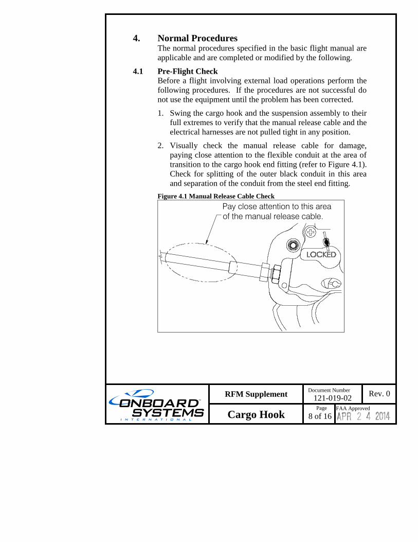
2. Visually check the manual release cable for damage,
paying close attention to the flexible conduit at the area of
transition to the cargo hook end fitting (refer to Figure 4.1).
Check for splitting of the outer black conduit in this area
and separation of the conduit from the steel end fitting.
Figure 4.1 Manual Release Cable Check
Pay close attention to this area
of the manual release cable.
Page
9 of 16
Rev. 0
Cargo Hook
RFM Supplement
FAA Approved
Document Number
121-019-02
4.1 Pre-Flight Check continued
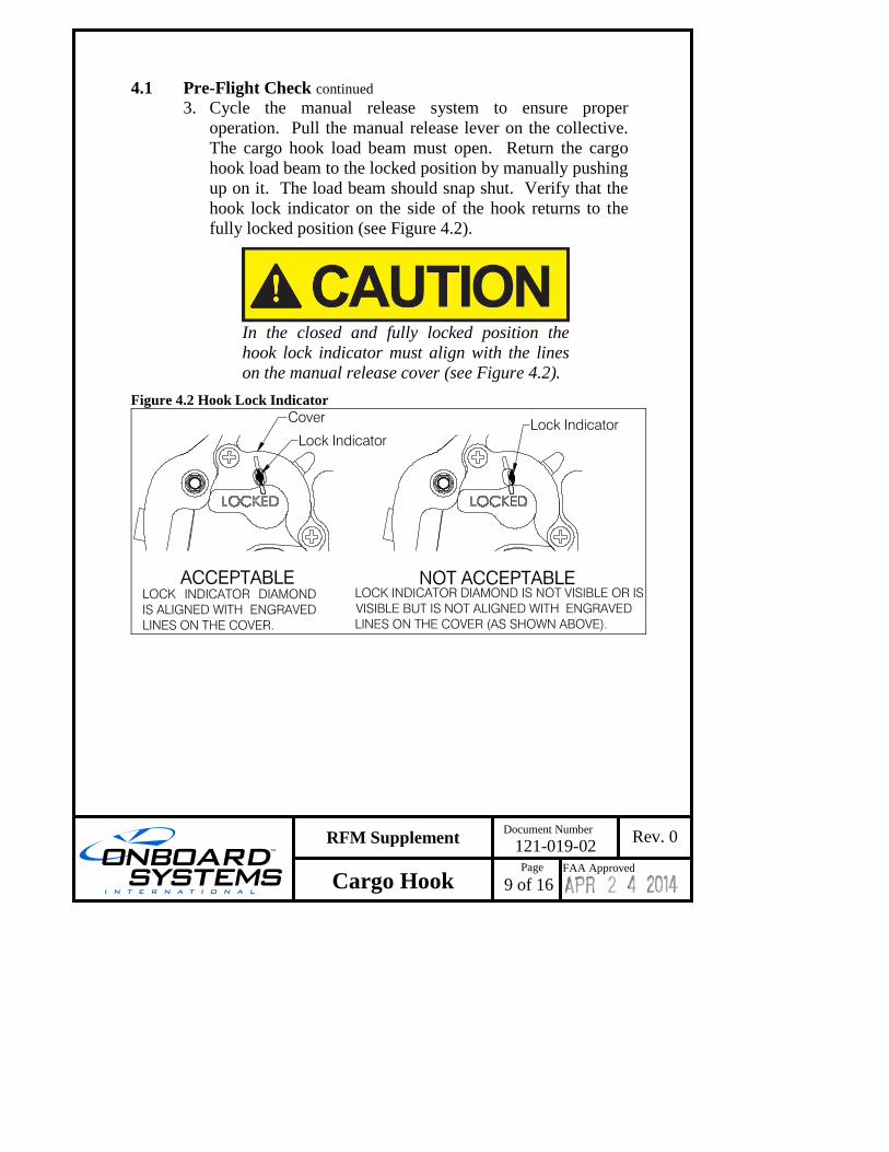
3. Cycle the manual release system to ensure proper
operation. Pull the manual release lever on the collective.
The cargo hook load beam must open. Return the cargo
hook load beam to the locked position by manually pushing
up on it. The load beam should snap shut. Verify that the
hook lock indicator on the side of the hook returns to the
fully locked position (see Figure 4.2).
In the closed and fully locked position the
hook lock indicator must align with the lines
on the manual release cover (see Figure 4.2).
Figure 4.2 Hook Lock Indicator

Page
10 of 16
Rev. 0
Cargo Hook
RFM Supplement
FAA Approved
Document Number
121-019-02
4.1 Pre-Flight Check continued 4. Cycle the electrical release system to ensure proper operation
per the following. Arm the cargo hook electrical release
system using the rotorcraft’s mission selector. Press the
CARGO REL pushbutton switch on the cyclic and ensure the
cargo hook opens. Return the cargo hook load beam to the
locked position by manually pushing up on it. The load beam
should snap shut. Verify that the hook lock indicator on the
side of the hook returns to the fully locked position (see
Figure 4.2). The cargo hook may be flown in the open
position to facilitate loading by a ground crew.
The cargo hook swing suspension interfaces
with the rotorcraft’s electrical release mission
selector and release pushbutton switch as
supplied by Airbus Helicopters. Consult the
Airbus Helicopters "Cargo Swing" Flight
Manual Supplement for operation of these
components.

Page
11 of 16
Rev. 0
Cargo Hook
RFM Supplement
FAA Approved
Document Number
121-019-02
4.1 Pre-Flight Check continued 5. Check the manual release cable rigging through the
window in the cargo hook manual release cover. With the
cargo hook load beam closed and locked, rotate the manual
release lever clockwise to remove the free play (the free
play is taken up when the hook lock indicator begins to
move, this is also readily felt as the lever rotates relatively
easily for several degrees as the free play is taken up) and
hold it in this position while checking the gap between the
release lever fork and the cable ball end as shown below.
Visually check that there is approximately a minimum gap
of 1/8” (3.2 mm) as shown in Figure 4.3.
Figure 4.3 Manual Release Cable Rigging 1
8" (3.2 mm) minimum
Manual Release Lever
Cable Ball End
Manual Release Lever fork
Page
12 of 16
Rev. 0
Cargo Hook
RFM Supplement
FAA Approved
Document Number
121-019-02
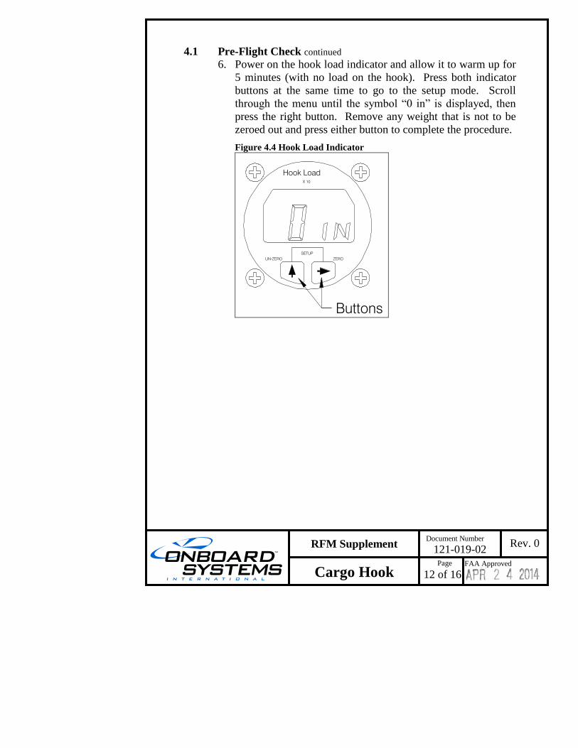
4.1 Pre-Flight Check continued 6. Power on the hook load indicator and allow it to warm up for
5 minutes (with no load on the hook). Press both indicator
buttons at the same time to go to the setup mode. Scroll
through the menu until the symbol “0 in” is displayed, then
press the right button. Remove any weight that is not to be
zeroed out and press either button to complete the procedure.
Figure 4.4 Hook Load Indicator
Hook Load
UN-ZERO
SETUP
X 10
ZERO
Buttons
Page
13 of 16
Rev. 0
Cargo Hook
RFM Supplement
FAA Approved
Document Number
121-019-02
4.2 Take-off
In wet weather, the ground operator should
wear thick rubber gloves. Before attaching the
load, discharge static electricity by placing a
ground wire or tube between the cargo hook
and ground.
1. Following attachment of the external load, slowly increase
the collective pitch and ascend vertically, maintaining the
rotorcraft directly above the load. When the slack in the
long line is removed and the suspension cables are tight,
dwell briefly before lifting the load from the surface.
2. Check torque required to hover with the external load.
3. Check for adequate directional control.
4. Take off into the wind, if possible, and ensure clearance of
the external load over obstacles.
4.3 Maneuvers
Control movements should be made gently and kept to a
minimum to prevent oscillation of the load on the cargo hook.
4.4 Approach with and Release of External Load
1. Perform the approach at minimum rate of descent.
2. Execute the approach to hover with sufficient height to
prevent the load from hitting obstacles on or being dragged
along the ground and then slowly descend vertically to set
the load on the ground.
3. Press the CARGO RELEASE switch on the cyclic to
release the external load from the cargo hook.
4. Visually check to ensure that the external load has been
released.
Page
14 of 16
Rev. 0
Cargo Hook
RFM Supplement
FAA Approved
Document Number
121-019-02
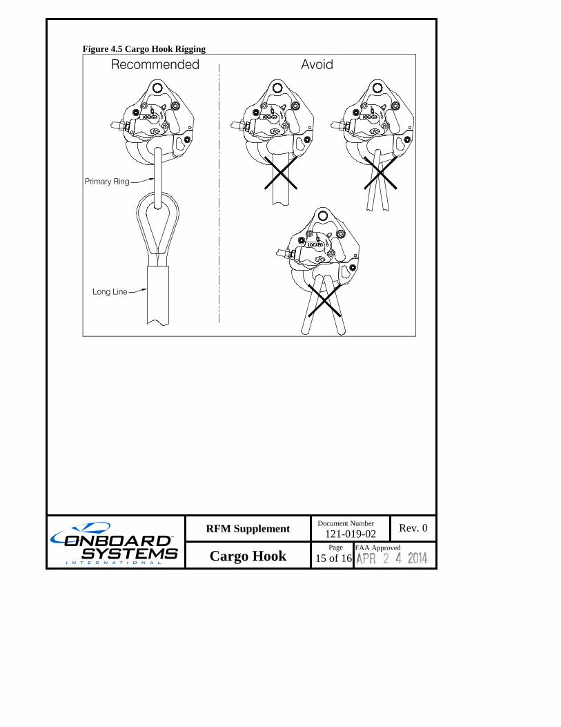
4.5 Cargo Hook Rigging
Extreme care must be exercised in rigging a load to the Cargo
Hook. Figure 4.5 shows a recommended rigging configuration
and rigging configurations to avoid.
The configurations shown are not intended to
represent all possibilities. It is the
responsibility of the operator to assure the
hook will function properly with the rigging
configuration being used.
Multiple load rings, nylon type straps (or
similar material) or rope must not be used
directly on the cargo hook load beam. If nylon
straps or rope must be used they should be
first attached to a steel primary ring. Verify
that the ring will freely slide off the load beam
when the cargo hook is opened. Only the
primary ring should be in contact with the
cargo hook load beam. See Figure 4.5.
Page
15 of 16
Rev. 0
Cargo Hook
RFM Supplement
FAA Approved
Document Number
121-019-02
Figure 4.5 Cargo Hook Rigging
Primary Ring
Long Line
Recommended Avoid
Page
16 of 16
Rev. 0
Cargo Hook
RFM Supplement
FAA Approved
Document Number
121-019-02
5. Performance The basic Flight Manual remains applicable when there is no
external load attached.
When there is an external load attached to the cargo hook,
performance will be reduced depending on its size, weight, and
shape.
The Load Weigh System is designed and installed as a means
of MONITORING the load (weight) suspended from the cargo
hook. Functional and performance characteristics have not
been determined on the basis of load cell indication or display.
Therefore, this instrument shall NOT be used as a primary
indication of performance and flight operation must NOT be
predicated on its use.