Rodillo ciclismo Elite Mag Force Elastogel
44
I GB D F E NL ISTRUZIONI INSTRUCTIONS BEDIENUNGSANLEITUNG MODE D’EMPLOI INSTRUCCIONES INSTRUCTIES force speed
-
Upload
mtbvirtual-mtbvirtual -
Category
Documents
-
view
228 -
download
2
description
Manual de instrucciones sobre el funcionamiento del rodillo de ciclismo Elite Mag Force Elastogel
Transcript of Rodillo ciclismo Elite Mag Force Elastogel

I
GB
D
F
E
NL
ISTRUZIONI
INSTRUCTIONS
BEDIENUNGSANLEITUNG
MODE D’EMPLOI
INSTRUCCIONES
INSTRUCTIES
force speed

ELITE, in collaborazione con BAYER, propone la soluzione ELASTOGEL, un tecnopolimero che applicato al rullino dell'unità di resistenza offre i seguenti vantaggi:
• RIDUCE DEL 50% IL DISTURBO SONORO (quantificato in dB*).• MIGLIORA L'ADERENZA DEL PNEUMATICO SUL RULLINO.• RIDUCE DEL 20% IL CONSUMO DEL PNEUMATICO.• RIDUCE LE VIBRAZIONI E MIGLIORA LA SENSIBILITA' DELLA PEDALATA.• MIGLIORA L'UTILIZZO DEI RULLI CON PNEUMATICI DA MOUNTAIN BIKE.
Le caratteristiche tecniche dell'ELASTOGEL sono: elevata elasticità,resistenza alla lacerazione, all'abrasione e resi-stenza agli oli e ai solventi.
*DECIBELIl rumore, suono sgradevole originato da rapide variazioni di pressione che si propagano attraverso l'aria mediante onde successive di compressione e di espansione,viene misurato in decibel (dB) la cui scala ha un andamento logaritmico. Ovvero, un suono di 60 dB ha un'intensità d'energia dieci volte superiore a un suono di 50 dB.
ELITE, in conjunction with BAYER, introduces ELASTOGEL , a technopolymer applied to the roller of the trainer resistance unit that offers the following advantages:
• 50% NOISE REDUCTION (quantified in dB*).• IMPROVES THE TIRE GRIP TO THE RESISTANCE ROLLER.• REDUCES TIRE WEAR BY 20%.• REDUCES VIBRATIONS AND REPLICATES REAL-LIFE RIDING.• IMPROVES THE PERFORMANCE OF THE TRAINER USING MTB TIRES.
A two part manufacturing process allows ELASTOGEL to withstand abrasions, solvents, oils and heat yet remains highly elastic.
*DECIBELNoise is an unpleasant sound originating from swift varia-tions of pressure that spread out through the air by means of continuous compressed and expanded waves and is measured in decibel (dB) which scale has a logarithmic trend. In other words, a sound of 60 dB has an energy intensity 10 times greater than a sound of 50 dB.
ELITE ist stolz, ein weiteres Produkt präsentieren zu können, das in Zusammenarbeit mit dem Chemiekonzern BAYER entstanden ist: ELASTOGEL. Bei ELASTOGEL handelt es sich um einen technologisch neuartigen Kunstoff, ein 2-Komponenten-Elastomer. Dieser wird als Laufrolle für die ELITE fitness-machines anstelle der Aluminiumwalze eingesetzt und bewirkt :
• REDUZIERUNG DES GERÄUSCHPEGELS UM 50% (GEMESSEN IN DB).• ERHEBLICHE VERBESSERUNG DES REIFENGRIPS AUF DER LAUFROLLE.• 20% WENIGER REIFENABRIEB.• VERMINDERUNG VON VIBRATIONEN UND ERHÖHUNG DER SENSIBILITÄT DES TRAINIERENDEN IN BEZUG AUDEN PEDALTRITT.• VERBESSERUNG DER KOMPATIBILITÄT MIT MTB-REIFEN.
Resultierend aus einem zweiphasig Herstellungsprozess ist ELASTOGEL in der Lage, Abrieb, Lösungsmitteln, Ölen und Hitze zu widerstehen und gleichzeitig eine extreme Elastizität zu bewahren.
*DECIBELJenes Geräusch ist unerwünscht, welches sich durch
TIRE WEAR
NOISE LEVEL OFTHE ROLLER
65.0
60.0
55.0
50.0
45.0
40.010
NOISE LEVEL OF THE ROLLER
SPEED (KM/h)
DE
CIB
EL
(dB
A)
73,5
64,4
80.0
75.0
70.0
20 30 40 50 60 70
57,6
ELASTOGEL ALUTEST MACHINE
ELASTOGEL ALU
0,25
0,2
0,15
0,1
0,05
00 4000 8000 12000 16000
TIRE WEAR
DISTANCE COVERED (KM)
TIR
E W
EA
R (
MM
)
0,2
0,16

Vibrationen und Druck ausbreitet. Der Geräuschpegel wird in Dezibel (dB) gemessen. Die Geräuschmessung basiert auf einem Logarithmus; dies bedeutet, dass ein Geräusch von 60 dB zehnmal so laut ist, wie ein Geräusch, das mit 50 dB gemessen wurde.
ELITE, en collaboration avec BAYER, à étudié l'ELASTOGEL il s'agit d'un technopolymer appliqué au rouleau d'entraine-ment ,qui offre les aventages suivants:
• RÉDUCTION DE 50% DU NIVEAU DE BRUIT (expri mé en db*).• AMÉLIORE L'ADHÉRENCE DU PNEU SUR LE GALET DE L'UNITÉ DE RÉSISTANCE.• REDUIT L'USURE DU PNEU DE PLUS DE 20%.• RÉDUIT LES VIBRATIONS ET AMÉLIORE LES SENSATIONS DUPÉDALAGE.• AMÉLIORE LES PERFORMANCES DU HOME TRAINER QUAND IL EST UTILISÉ AVEC DES PNEUS V.T.T.
Le processus de production bi-composant permet à l'ELA-STOGEL de résister aux abrasifs, solvants,huiles, chaleur, et de garder ses caractéristiques elastiques.*DECIBELLe bruit provient des variations rapides de pressions et dépressions et il provoque des désagréments , on le mesure en décibels , et l'échelle des mesures est logari-thmique , un bruit de 60dB à une puissance dix fois plus forte qu'un bruit de 50dB.
ELITE, en colaboración con BAYER, propone la solución ELASTOGEL, un tecnopolímero que aplicado al rodillo de la unidad de resistencia ofrece las siguientes ventajas:
• REDUCE DEL 50% LA MOLESTIA DEL RUIDO (cuantificado en dB*).• MEJORA LA ADHERENCIA DEL NEUMÁTICO SOBRE EL RODILLO.• REDUCE DEL 20% EL CONSUMO DEL NEUMÁTICO.• REDUCE LAS VIBRACIONES Y MEJORA LA SENSIBILIDAD DE LA PEDALADA.• MEJORA EL USO DE LOS TRAINER CON NEUMÁTICOS DE MOUNTAIN BIKE.
Las características técnicas del ELASTOGEL son:elevada elasticidad, resistencia al desgarre, a la abrasión y a los aceites y disolventes.
*DECIBELEl ruido, sonido desagradable originado por rápidas varia-ciones de presión que se propagan a través del aire mediante ondas sucesivas de compresión y de expansión, viene medido en decibelios (dB) cuya escala tiene un desarrollo logarítmico. O sea, un ruido de 60 dB tiene una intensidad de energía diez veces superior a uno de 50 dB.
ELITE: in samenwerking met BAYER, is trots de ELASTOGEL oplossing voor te stellen, een technopolymer aangebracht op de roller van de trainer weesrtand unit welke de onderstaande voordelen biedt:
• VERMINDERT HET GELUIDSNIVEAU MET 50% (gemeten in Db*).
• VERBETERT DE GRIP VAN DE BAND OP DE WEERSTAND ROLLER.• VERMINDERT BAND SLIJTAGE TOT 20%.• VERMINDERT VIBRATIES EN VERHOOGT HET GEVOEL TIJDENS HET TRAPPEN MET DE PEDALEN.• VERBETERT DE PRESTATIE VAN DE TRAINER BIJ GEBRUIK VAN MTB BANDEN.
Een tweeledig fabrikage proces met Elastogel zorgt voor minder slijtage en hogere duurzaamheid, olie en warmteblijven toch hoog elastisch.
*DECIBELLawaai is een onplezierig geluid wat onstaat door snelle verschillen in druk welke zich door de lucht verspreidt door middel van drukgolven, en gemeten wordt in decibellen (dB) op een logaritmisch schaal. Met andere woorden een geluid van 60 dB heeft 10 maal grotere geluidsintensiteit dan een geluid van 50 dB.

• IMPORTANTE 6
• INTRODUZIONE 6
• ASSEMBLAGGIO CAVALLETTO 7
• MONTAGGIO UNITÀ 7
• INSTALLAZIONE DELLA BICICLETTA 7
• RIMOZIONE DELLA BICICLETTA 9
• ATTENZIONI 9
• CONSIGLI PER L'UTILIZZO 10
• GARANZIA 39
ITALIA
NO
• IMPORTANT 11
• INTRODUCTION 11
• ASSEMBLING THE TRAINER BASE 12
• ASSEMBLING THE UNIT 12
• BICYCLING INSTALLATION 12
• BICYCLE REMOVAL 13
• ATTENTION 13
• ADVISE FOR THE USE 15
• WARRANTY 39
ENG
LISH • WICHTIGER HINWEIS 16
• EINLEITUNG 16
• MONTAGE DES GRUNDRAHMENS 17
• MONTAGE DER WIDERSTANDSEINHEIT 17
• INSTALLIERUNG DES FAHRRADES 17
• ABNEHMEN DES FAHRRADES 19
• ACHTUNG 19
• HINWEISE ZUM GEBRAUCH 20
• GARANTIE 39
DEU
TSCH

• IMPORTANTE 26
• INTRODUCCIÓN 26
• ENSAMBLAJE DEL CABALLETE 27
• MONTAJE DE LA UNIDAD 27
• INSTALACIÓN DE LA BICICLETA 27
• CÓMO SACAR LA BICICLETA 29
• ATENCIÓN 29
• CONSEJOS DE USO 30
• GARANTÍA 40
• BELANGRIJK 31
• INLEIDING 31
• ASSEMBLAGE VAN DE STANDAARD 32
• ASSEMBLAGE VAN DE UNIT 32
• DE FIETS INSTALLEREN 32
• DE FIETS VERWIJDEREN 34
• AANDACHTSPUNTEN 34
• GEBRUIKSADVIEZEN 35
• GARANTIE 40
FRA
NÇ
AIS
ESPAÑ
OL
DU
TCH
• IMPORTANT 21
• INTRODUCTION 21
• ASSEMBLAGE DU CHEVALET 22
• MONTAGE DE L’UNITÉ 22
• INSTALLATION DU VÉLO 22
• ENLEVEMENT DU VÉLO 24
• MISES EN GARDE 24
• CONSEILS POUR L’UTILISATION 25
• GARANTIE 39

Molte grazie per aver acquistato un rullo d'allenamento Elite.
IMPORTANTE
Non frenare durante l'utilizzo del trainer, ciò
danneggia irreparabilmente il rullino e il
pneumatico.
L’unità di resistenza si riscalda sensibilmente
quando in uso. È necessario aspettare che si
raffreddi prima di toccare il volano.
INTRODUZIONE
Verificare la presenza di tutti i componenti seguenti.
N°1 unità di resistenza (Rif. A)N°1 cavalletto (Rif.B) boccola sinistra (Rif.C) boccola destra (Rif.D) vite di fissaggio (Rif.E) anello di bloccaggio (Rif.F) manovella (Rif.G) spring plate (Rif.H)N°1 sacchetto accessori: 1 chiave esagonale 3 viti M6 x16mm (Rif.I) 2 rondelle Ø6mm (Rif.L)N°1 bloccaggio rapido (Rif.M)
ITALIA
NO
I
6
ASSEMBLAGGIO CAVALLETTO
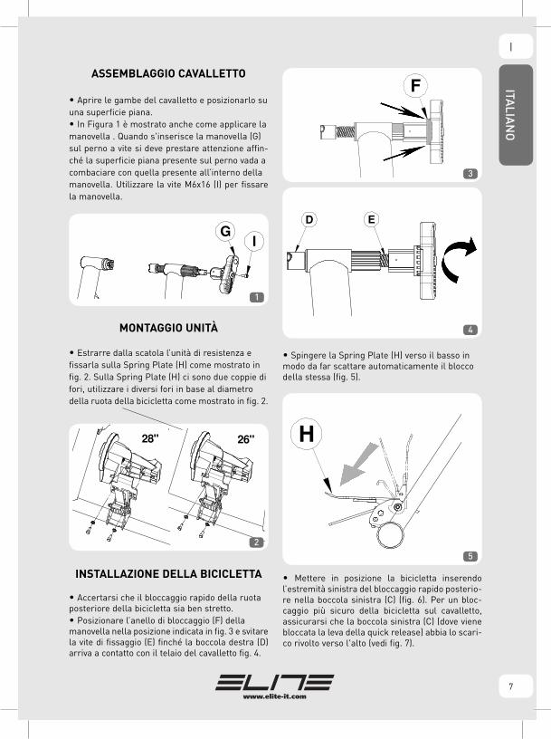
• Aprire le gambe del cavalletto e posizionarlo suuna superficie piana.• In Figura 1 è mostrato anche come applicare lamanovella . Quando s'inserisce la manovella (G)sul perno a vite si deve prestare attenzione affin-ché la superficie piana presente sul perno vada acombaciare con quella presente all’interno dellamanovella. Utilizzare la vite M6x16 (I) per fissare la manovella.
MONTAGGIO UNITÀ
• Estrarre dalla scatola l’unità di resistenza efissarla sulla Spring Plate (H) come mostrato infig. 2. Sulla Spring Plate (H) ci sono due coppie difori, utilizzare i diversi fori in base al diametrodella ruota della bicicletta come mostrato in fig. 2.
INSTALLAZIONE DELLA BICICLETTA
• Accertarsi che il bloccaggio rapido della ruotaposteriore della bicicletta sia ben stretto.• Posizionare l’anello di bloccaggio (F) dellamanovella nella posizione indicata in fig. 3 e svitare la vite di fissaggio (E) finché la boccola destra (D) arriva a contatto con il telaio del cavalletto fig. 4.
• Spingere la Spring Plate (H) verso il basso inmodo da far scattare automaticamente il bloccodella stessa (fig. 5).
• Mettere in posizione la bicicletta inserendo l’estremità sinistra del bloccaggio rapido posterio-re nella boccola sinistra (C) (fig. 6). Per un bloc-caggio più sicuro della bicicletta sul cavalletto, assicurarsi che la boccola sinistra (C) (dove viene bloccata la leva della quick release) abbia lo scari-co rivolto verso l'alto (vedi fig. 7).
ITALIA
NO
I
7
F
26"28"
GI
1
2
3
4
5
ITALIA
NO
I
8
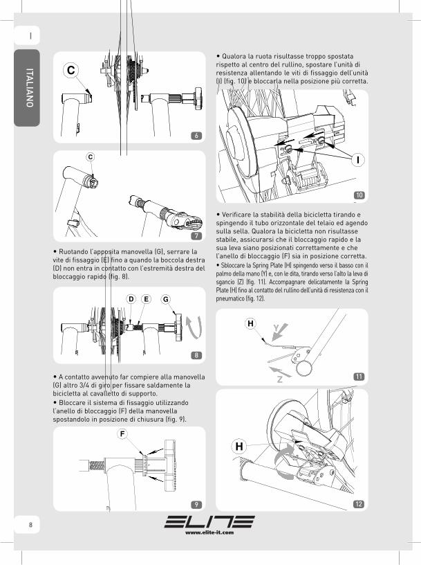
• Ruotando l’apposita manovella (G), serrare lavite di fissaggio (E) fino a quando la boccola destra (D) non entra in contatto con l’estremità destra del bloccaggio rapido (fig. 8).
• A contatto avvenuto far compiere alla manovella (G) altro 3/4 di giro per fissare saldamente labicicletta al cavalletto di supporto.• Bloccare il sistema di fissaggio utilizzandol’anello di bloccaggio (F) della manovellaspostandolo in posizione di chiusura (fig. 9).
• Qualora la ruota risultasse troppo spostatarispetto al centro del rullino, spostare l’unità diresistenza allentando le viti di fissaggio dell’unità (I) (fig. 10) e bloccarla nella posizione più corretta.
• Verificare la stabilità della bicicletta tirando espingendo il tubo orizzontale del telaio ed agendosulla sella. Qualora la bicicletta non risultassestabile, assicurarsi che il bloccaggio rapido e lasua leva siano posizionati correttamente e chel’anello di bloccaggio (F) sia in posizione corretta.• Sbloccare la Spring Plate (H) spingendo verso il basso con il palmo della mano (Y) e, con le dita, tirando verso l’alto la leva di sgancio (Z) (fig. 11). Accompagnare delicatamente la Spring Plate (H) fino al contatto del rullino dell’unità di resistenza con il pneumatico (fig. 12).
C
C
D E G
F
6
7
8
129
10
H Y
Z 11
ITALIA
NO
I
9
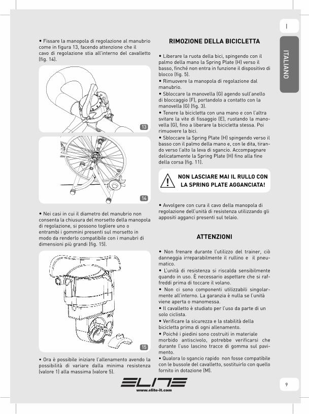
• Fissare la manopola di regolazione al manubriocome in figura 13, facendo attenzione che ilcavo di regolazione stia all’interno del cavalletto (fig. 14).
• Nei casi in cui il diametro del manubrio nonconsenta la chiusura del morsetto della manopoladi regolazione, si possono togliere uno oentrambi i gommini presenti sul morsetto inmodo da renderlo compatibile con i manubri didimensioni più grandi (fig. 15).
• Ora è possibile iniziare l’allenamento avendo la possibilità di variare dalla minima resistenza (valore 1) alla massima (valore 5).
RIMOZIONE DELLA BICICLETTA
• Liberare la ruota della bici, spingendo con ilpalmo della mano la Spring Plate (H) verso ilbasso, finché non entra in funzione il dispositivo diblocco (fig. 5).• Rimuovere la manopola di regolazione dalmanubrio.• Sbloccare la manovella (G) agendo sull’anellodi bloccaggio (F), portandolo a contatto con lamanovella (G) (fig. 3).• Tenere la bicicletta con una mano e con l’altrasvitare la vite di fissaggio (E), ruotando la mano-vella (G), fino a liberare la bicicletta stessa. Poirimuovere la bici.• Sbloccare la Spring Plate (H) spingendo verso ilbasso con il palmo della mano e, con le dita, tiran-do verso l’alto la leva di sgancio. Accompagnaredelicatamente la Spring Plate (H) fino alla finedella corsa (fig. 11).
• Avvolgere con cura il cavo della manopola diregolazione dell’unità di resistenza utilizzando gliappositi agganci presenti sul telaio.
ATTENZIONI
• Non frenare durante l’utilizzo del trainer, ciò danneggia irreparabilmente il rullino e il pneu-matico.• L’unità di resistenza si riscalda sensibilmente quando in uso. È necessario aspettare che si raf-freddi prima di toccare il volano.• Non ci sono componenti utilizzabili singolar-mente all’interno. La garanzia è nulla se l’unitàviene aperta o manomessa.• Il cavalletto è studiato per l’uso da parte di unsolo ciclista.• Verificare la sicurezza e la stabilità dellabicicletta prima di ogni allenamento.• Poiché i piedini sono costruiti in materialemorbido antiscivolo, potrebbe verificarsi che durante l’uso lascino tracce di gomma sul pavi-mento.• Qualora lo sgancio rapido non fosse compatibile con le bussole del cavalletto, sostituirlo con quello fornito in dotazione (M).
13
14
15
NON LASCIARE MAI IL RULLO CON
LA SPRING PLATE AGGANCIATA!

ITALIA
NO
I
10
CONSIGLI PER L'UTILIZZO
• Pressione consigliata della ruota posteriore:7 - 8 atmosfere per pneumatico da corsa; 3.5 - 4atmosfere per pneumatico MTB. Per casi partico-lari attenersi alla pressione consigliata dalcostruttore dei pneumatici.• Per un minor consumo del pneumatico e una migliore aderenza al rullino, consigliamo di utiliz-zare pneumatici larghi 23 mm a carcassa rigida.• Per una minor rumorosità, una maggioreaderenza del pneumatico sul rullino e unariduzione delle vibrazioni, utilizzare pneumaticislick (anche su Mountain bike).• È preferibile utilizzare bloccaggi d’acciaio.• Prima dell'uso, pulire il pneumatico con alcool oacqua.• Se il perno dello sgancio rapido fornito sporge più di 3 mm dal dado di fissaggio tagliare la parte sporgente (fig. 16).
NO OK 16

Congratulations on your purchase of an Elite hometrainer.
IMPORTANT
Do not stop the rotation of the bicycle
wheel by using caliper or disk brake. This
seriously damages the roller and the tire.
The resistance unit may warm-up while in
use. Let it cool down before handling it and
touching the flywheel.
INTRODUCTION
Check the presence of all the following compo-
nents.
N°1 resistance unit (Rif. A)N°1 trainer base (Rif.B) left support cup (Rif.C) right support cup (Rif.D) axle support (Rif.E) locking ring (Rif.F) handle (Rif.G) spring plate (Rif.H)N°1 parts bag: 1 Allen wrench 3 M6 x 16 mm bolts (Rif.I) 2 Ø6 washers (Rif.L)N°1 QR skewer (M)
GB
11
ENG
LISH

ASSEMBLING THE TRAINER BASE
• Open the trainer base and set it on a flat, stablesurface.•Picture 1 shows how to apply the handle (G). When fitting the handle to the axle support,make sure the flat surface of the axle screw matches the inside of the handle. Use the M6x16 (I) screw to fix the handle.
ASSEMBLING THE UNIT
• Remove the resistance unit from its carton and install it on the Spring Plate as shown in illustra-tion nr. 2. On the Spring Plate (H) there are two pairs of holes, use the holes according to the rear wheel diameter, as show in illustration nr. 2.
BICYCLING INSTALLATION
• Make sure that the bicycle’s rear wheel skeweris tight.• Position the locking ring (F) as shown in illustra-tion nr. 3 and using the handle, loosen the axlesupport (E) until the right support cup (D) comes in contact with the trainer’s frame (illustration nr. 4).
• Push the Spring Plate (H) down as far as possi-ble towards the floor to automatically engage theSpring Plate lock (Fig. 5).
• Carefully lift your bicycle in position, insert therear wheel axle from the left hand side into the lefthand axle support cup (C) (as shown in illustrationnr. 6). To have a more secure locking of the bicycle on the frame, the left support cup (C) (where the QR lever gets blocked) is turned up (Fig. 7).
GI
F
26"28"
1
2
3
4
5
ENG
LISH
GB
12

• Using the handle (G), tighten the right hand sideaxle support (E) until the right support cup (D) comes in contact with the bicycle’s right side QR hub (Fig. 8).
• After contact is made, tighten the handle (G) for about 3/4 of a rotation to fix the bicycle to the frame.• Lock the fixing mechanism by using the locking ring (F) of the handle towards locking position (Fig. 9).
• If the bicycle’s rear wheel is not centered withthe drum, move the resistance unit sideways byloosening the screws (I) (Fig. 10) and lock it in the correct position.
• Test that the bicycle is secure by pushing and pulling the top tube and operating on the sadd-le. If the bicycle is not stable, make sure that the QR lever and hub are positioned correctly, and the locking ring (F) is in the right position.• Release the Spring Plate (H) lock by pushing down on the Spring Plate with the palm of your hand (Y) and, with your fingers, pull upwards the Spring Plate release (Z) (Fig. 11). Allow the Spring Plate (H) to slowly rotate upwards until the resistance unit’s drum makes contact with the tyre. (Fig. 12).
C
C
D E G
F
6
7
8
129
10
H Y
Z 11
GBEN
GLISH
13

• Install the remote regulation shifter on the han-dlebar as shown in illustration 13, make sure that the regulation cable is inside the trainer base (Fig. 14).
• If the handlebar diameter is such that the clamp of the remote regulation shift cannot be tightened, either one or both of the rubber linings on the clamp may be removed, allowing it to be adapted to larger diameters (Fig.15).
• Now you may begin training. Resistance can be adjusted from a minimum (value 1) to a maximum (value 5).
BICYCLE REMOVAL
• Free the bicycle’s tire from the resistance-unit’sdrum by pushing the Spring Plate (H) down withthe palm of your hand until the Spring Platemechanism reaches it’s locked position (Fig. 5).• Remove the remote regulation shifter from thehandlebar.• Loosen the handle (G) by pushing the lockingring (F) against the handle (G) (Fig. 3).• While holding the bicycle, loosen the locking axle (E) rotating the handle (G) until the bicycle is free. Then remove the bicycle.• Release the Spring Plate (H) lock by pushingdown on the Spring Plate with the palm of yourhand and, with your fingers, pull gently upwardsthe Spring Plate (H) release (Fig. 11).
• Carefully wind the remote regulation shifter ofthe trainer resistance unit around the relevanthooks located on the frame.
ATTENTION
• Do not brake when using the trainer, as this can permanently damage the roller and the tyre. • The resistance unit may warm-up while in use. Let it cool down before handling it and touching the flywheel.• There are no user serviceable parts. The warranty is void if opened or tampered for any reason.• The frame is intended for single-rider bicycles only.• Control the security and the stability of the bicycle before every hometrainer.• The pressure feet are made of soft antislip material and could leave rubber marks on the floor during use.• If the quick release is not compatible with the bushings of the stand, replace it with the one sup-plied (M).
13
14
15
DO NOT LEAVE THE TRAINER
UNATTENDED WITH THE SPRING
PLATE MECHANISM IN LOCKED
(DOWN) POSITION!
ENG
LISH
GB
14

ADVISE FOR THE USE
• Suggested pressure of the rear tire: 7-8 atmos-pheres for racing wheels; 3.5-4 atmospheres forMTB wheels. For particular cases follow thepressure suggested by the tire manufacturer.• For less tyre wear and better grip on the roller, it is advisable to use tires of 23 mm width and wider rigid casing.• Slick tyres (even for MTB bicycles) are sugge-sted to reduce the noise level and vibrations and toimprove the grip of the tyre on the roller.• We suggest to use a steel headed quick releasehub.• Before each training session, clean the bicycletyre with water or alcohol.• If the pin of the quick release supplied protrudes more than 3 mm from the fixing nut, cut off the protruding part (fig. 16).
NO OK 16
GBEN
GLISH
15

Wir danken Ihnen für den Kauf eines Elite Heimtrainers.
WICHTIGER HINWEIS
Während des Gebrauchs des Heimtrainers
auf keinen Fall bremsen, da sonst die Rolle
und die Reifen stark beschädigt werden kön-
nen!
Die Widerstandseinheit erwärmt sich beim
Gebrauch spürbar. Bitte lassen Sie sie
abkühlen, bevor Sie das Schwungrad anfas-
sen.
EINLEITUNG
Überprüfen Sie, dass alle nachstehenden Komponenten vorhanden sind:
1 St. Widerstandseinheit (Bez. A)1 St. Grundrahmen des Trainers (Bez. B) linke Schnellspanner-Aufnahme (Bez. C) rechte Schnellspanner-Aufnahme (Bez. D) Befestigungsschraube (Bez. E) Sicherungsring (Bez. F) Handgriff (Bez. G) Federplatte (Bez. H)1 St. Polybeutel mit: 1 Inbus-Schlüssel 3 Stück M6x16 Schrauben (Bez. I) 2 Stück Ø6mm Unterlegscheiben (Bez. L)1 St. Schnellspanner (Bez. M)
16
DEU
TSCH
D
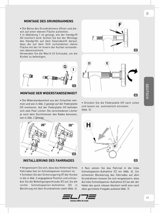
MONTAGE DES GRUNDRAHMENS
• Die Beine des Grundrahmens öffnen und die-sen auf einer ebenen Fläche aufstellen.• In Abbildung 1 ist gezeigt, wie der Handgriff (G) montiert wird. Achten Sie bei der Montage des Handgriffs auf dem Gewindestift darauf, dass die auf dem Stift vorhandenen ebene Fläche mit der im Innern der Kurbel vorhande-nen übereinstimmt. Verwenden Sie die M6x16 (I) Schraube, um die Kurbel zu befestigen.
MONTAGE DER WIDERSTANDSEINHEIT
• Die Widerstandseinheit aus der Schachtel neh-men und wie in Abb. 2 gezeigt auf der Federplatte (H) montieren. Auf der Federplatte (H) befinden sich zwei Paar Löcher. Die verschiedenen Löcher je nach dem Durchmesser des Rades benutzen, wie in Abb. 2 gezeigt.
INSTALLIERUNG DES FAHRRADES
• Vergewissern Sie sich, dass das Hinterrad Ihres Fahrrades fest im Schnellspanner montiert ist.• Schieben Sie den Sicherungsring (F) der Kurbel in die in Abb. 3 angegebene Position und schrau-ben Sie die Befestigungsschraube (E) auf, bis die rechte Schnellspanner-Aufnahme (D) in Berührung mit dem Grundrahmen steht (Abb. 4).
• Drücken Sie die Federplatte (H) nach unten und lassen sie automatisch einrasten (Abb. 5).
• Nun setzen Sie das Fahrrad in die linke Schnellspanner-Aufnahme (C) ein (Abb. 6). Zur sichereren Blockierung des Fahrrades auf dem Grundrahmen müssen Sie sich vergewissern, dass die linke Schnellspanner-Aufnahme (C) (an der der Hebel des quick release blockiert wird) eine nach oben gerichtete Freigabe aufweist (Abb. 7).
17
F
26"28"
GI
1
2
3
4
5
DD
EUTSC
H

18
• Nun ziehen Sie die Befestigungsschraube (E) des Trainers durch Drehen des Handgriffs (G) an, bis die rechte Schnellspanner-Aufnahme (D) das rechte Ende des Schnellspanners berührt (Abb. 8).
• Nach erfolgter Berührung drehen Sie den Handgriff (G) noch 3/4 Umdrehung weiter, um das Fahrrad fest auf dem Grundrahmen zu verankern.• Sichern Sie diese Verschraubung, indem Sie den Sicherungsring (F) des Handgriffs in Schließposition schieben (Abb. 9).
• Sollte sich das Rad als im Verhältnis zur Rollenmitte zu sehr verlagert erweisen, muss die Widerstandseinheit verschoben werden, indem die
Befestigungsschrauben der Einheit (I) (Abb. 10) gelo-ckert und die Einheit in der korrektesten Position blo-ckiert wird.
• Nun prüfen Sie bitte durch Rütteln an Oberrohr des Rahmens und Sattel, ob das Fahrrad fest im Trainerrahmen steht. Falls sich das Fahrrad als nicht stabil erweist, muss sichergestellt werden, dass der Schnellspanner und sein Hebel korrekt positioniert sind und dass der Sicherungsring (F) sich in der kor-rekten Position befindet.• Die Federplatte (H) lösen, indem Sie sie mit der Handfläche (Y) nach unten drücken und mit den Fingern den Hebel zur Freigabe nach oben ziehen (Z) (Abb. 11). Die Federklappe (H) vorsichtig bis zur Berührung der Rolle der Widerstandseinheit mit dem Reifen (Abb. 12) begleiten.
C
C
D E G
F
6
7
8
12
9
10
H Y
Z 11
DEU
TSCH
D

19
• Den Verstellhebel so wie in Abb. 13 gezeigt am Lenker befestigen; dabei darauf achten, dass das Einstellkabel sich an der Innenseite des Grundrahmens befindet (Abb. 14).
• Falls der Durchmesser des Lenkers das Schließen der Einstellgriffklemme nicht erlaubt, können eins oder beide der an der Klemme vorhandenen Gummiteile entfernt werden, damit die Klemme auch auf größere Lenker passt (Abb. 15).
• Jetzt kann mit dem Training begonnen werden; man hat die Möglichkeit, den Widerstand von 1 (Mindestwert) bis 5 (Höchstwert) einzustellen.
ABNEHMEN DES FAHRRADES
• Das Rad freigeben, indem die Federplatte (H) mit der Handfläche nach unten gedrückt wird, bis die Sperrvorrichtung einrastet (Abb. 5).• Den Einstellgriff vom Lenker abnehmen.• Lösen Sie den Handgriff (G), indem Sie auf den Sicherungsring (F) einwirken und ihn in Berührung mit dem Handgriff (G) bringen (Abb. 3).• Das Fahrrad mit einer Hand halten und mit der anderen die Befestigungsschraube (E) aufschrauben, wobei der Handgriff (G) gedreht wird, bis das Fahrrad freigegeben ist. Dann das Fahrrad abnehmen.• Die Federplatte (H) lösen, indem Sie sie mit der Handfläche nach unten drücken und mit den Fingern den Hebel zur Freigabe nach oben ziehen. Die Federklappe (H) vorsichtig bis zum Ende des Hubs begleiten (Abb. 11).
• Das Kabel des Verstellhebels für die Widerstandseinheit versorgen, indem es sorgfältig um die am Rahmen vorhandenen Haken gelegt wird.
ACHTUNG
• Während des Gebrauchs des Radsimulators auf keinen Fall bremsen, da sonst die Rolle und die Reifen stark beschädigt werden können!• Die Widerstandseinheit erwärmt sich beim Gebrauch spürbar. Bitte lassen Sie sie abkühlen, bevor Sie das Schwungrad anfassen.• Im Innern befinden sich keine einzeln benutzba-ren Komponenten. Die Garantie erlischt, wenn Sie die Einheit öffnen oder manipulieren. • Das Fitness-Gerät ist ausschließlich für den Gebrauch durch einen einzigen Fahrer geeignet und zugelassen. • Die Sicherheit und die Stabilität des Fahrrades vor jedem Training überprüfen.• Da die Standfüße aus weichem, rutschfestem Material gefertigt sind, kann es vorkommen, dass Materialreste auf dem Fußboden zurück bleiben. • Wenn der Schnellspanner nicht kompatibel mit den Schnellspanner-Aufnahmen des Grundrahmens ist, wechseln Sie ihn gegen das in der Lieferung enthalte-ne Modell (M) aus.
13
14
15
DEN ROLLENTRAINER NIEMALS
MIT EINGERASTETER
FEDERPLATTE ZURÜCKLASSEN!
DD
EUTSC
H

20
HINWEISE ZUM GEBRAUCH
• Wir empfehlen folgenden Reifendruck des Hinterrades:- Rennreifen: 7-8 atm.- MTB-Reifen 3.5 - 4 atm. In besonderen Fällen den vom Hersteller der Reifen empfohlenen Druck beachten.• Für einen geringeren Verschleiß des Reifens und eine bessere Haftung an der Rolle empfehlen wir die Verwendung von 23 mm breiten Reifen mit steifer Karkasse.• Für eine geringere Geräuschentwicklung, eine bessere Haftung des Reifens an der Rolle und eine Verminderung der Vibrationen empfehlen wir Slick-Reifen (auch bei Mountainbikes).• Wir empfehlen Schnellspanner aus Stahl.• Vor jedem Training reinigen Sie den Reifen bitte mit Alkohol oder Wasser.• Wenn der Stift des mitgelieferten Schnellspanners mehr als 3 mm aus der Befestigungsmutter herau-sragt, den hervorstehenden Teil abschneiden (Abb. 16).
NO OK 16
DEU
TSCH
D
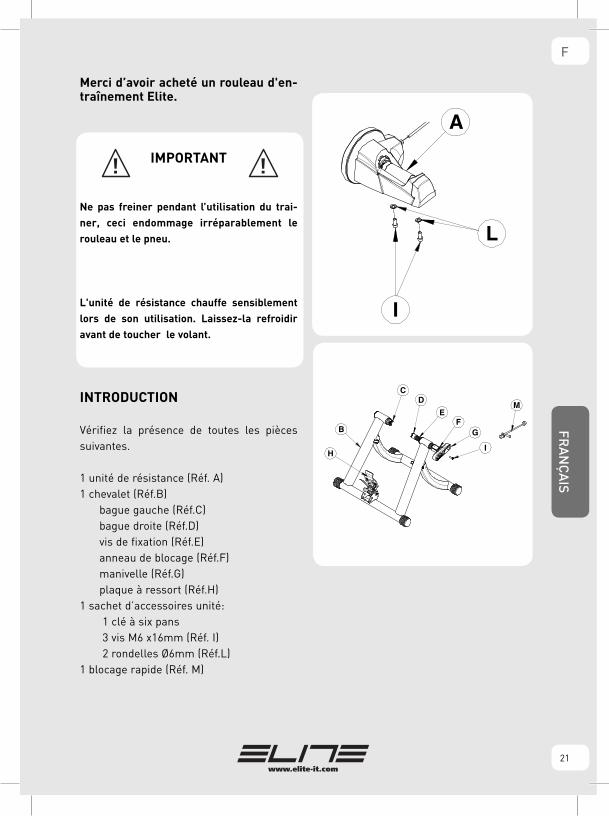
Merci d’avoir acheté un rouleau d'en-traînement Elite.
IMPORTANT
Ne pas freiner pendant l’utilisation du trai-
ner, ceci endommage irréparablement le
rouleau et le pneu.
L'unité de résistance chauffe sensiblement
lors de son utilisation. Laissez-la refroidir
avant de toucher le volant.
INTRODUCTION
Vérifiez la présence de toutes les pièces suivantes.
1 unité de résistance (Réf. A)1 chevalet (Réf.B) bague gauche (Réf.C) bague droite (Réf.D) vis de fixation (Réf.E) anneau de blocage (Réf.F) manivelle (Réf.G) plaque à ressort (Réf.H)1 sachet d’accessoires unité: 1 clé à six pans 3 vis M6 x16mm (Réf. I) 2 rondelles Ø6mm (Réf.L)1 blocage rapide (Réf. M)
FFR
AN
ÇA
IS
21

ASSEMBLAGE DU CHEVALET
• Ouvrir les pieds du chevalet et le positionner surune surface plane.• Sur la figure n. 1 voyez comment appliquer lamanivelle(G). Quand on insère la manivelle sur le pivot à vis, il faut veiller à ce que la surface planeprésente sur le pivot coïncide avec la surface plane présente à l’intérieur de la manivelle. Utilisez la vis M6x16 (I) pour fixer la manivelle.
MONTAGE UNITÉ
• Extraire l’unité de résistance de l’emballage et la fixer sur la plaque à ressort (H) de la façon indi-quée sur la fig. 2. Deux couples de trous sont réalisés sur la plaque à ressort (H). Choisir les trous à utiliser en fonction du diamètre de la roue du vélo, selon les indications de fig. 2.
INSTALLATION DU VÉLO
• S’assurer que le blocage rapide de la roue arriè-re du vélo soit bien serré.• Positionner l'anneau de blocage (F) de la manivelle dans la position indiquée sur fig. 3 et dévisser la vis de fixation (E) jusqu’à ce que la bague droite (D) entre en contact avec le châssis du chevalet (fig.4).
• Pousser la plaque à ressort (H) vers le bas jusqu’à faire enclencher automatiquement le blo-cage de cette dernière (fig. 5).
• Mettre le vélo en position en introduisant l’extré-mité gauche du blocage instantané arrière dans la bague gauche (C) (fig. 6). Afin de bloquer plus sûrement le vélo sur le chevalet, s’assurer que la bague gauche (C) (où le levier du quick release est bloqué) est le déchargement orienté vers le haut (voir fig. 7).
F
26"28"
2
3
4
5
FRA
NÇ
AIS
F
22
GI
1
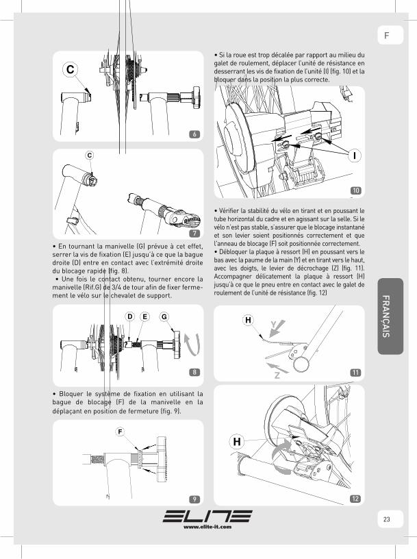
• En tournant la manivelle (G) prévue à cet effet, serrer la vis de fixation (E) jusqu’à ce que la bague droite (D) entre en contact avec l’extrémité droite du blocage rapide (fig. 8). • Une fois le contact obtenu, tourner encore la manivelle (Rif.G) de 3/4 de tour afin de fixer ferme-ment le vélo sur le chevalet de support.
• Bloquer le système de fixation en utilisant la bague de blocage (F) de la manivelle en ladéplaçant en position de fermeture (fig. 9).
• Si la roue est trop décalée par rapport au milieu du galet de roulement, déplacer l’unité de résistance en desserrant les vis de fixation de l’unité (I) (fig. 10) et la bloquer dans la position la plus correcte.
• Vérifier la stabilité du vélo en tirant et en poussant le tube horizontal du cadre et en agissant sur la selle. Si le vélo n’est pas stable, s’assurer que le blocage instantané et son levier soient positionnés correctement et que l'anneau de blocage (F) soit positionnée correctement.• Débloquer la plaque à ressort (H) en poussant vers le bas avec la paume de la main (Y) et en tirant vers le haut, avec les doigts, le levier de décrochage (Z) (fig. 11). Accompagner délicatement la plaque à ressort (H) jusqu’à ce que le pneu entre en contact avec le galet de roulement de l’unité de résistance (fig. 12)
C
C
D E G
F
6
7
8
129
10
H Y
Z 11
FFR
AN
ÇA
IS
23

• Fixer le bouton de réglage au guidon de la façon indiquée sur la figure 13, en veillant à ce que le câble de réglage reste à l’intérieur du chevalet (fig.14).
• Si le diamètre du guidon ne permet pas de fer-mer le serrage du bouton de réglage, on peut enlever un ou les deux caoutchoucs présents sur le serrage de façon à l’adapter aux guidons de dimensions plus grandes (fig. 15).
• Maintenant on peut commencer l’entrainement en ayant la possibilité de passer de la résistance mini-mum (valeur 1) à la maxi (valeur 5).
ENLEVEMENT DU VÉLO
• Dégager la roue du vélo en poussant vers le bas la plaque à ressort (H) avec la paume de la main jusqu’à ce que le dispositif de blocage entre en fon-ction (fig. 5).• Enlever le bouton de réglage du guidon.• Débloquer la manivelle (G) en agissant sur la bague de blocage (F), en portant celle-ci en contact avec la manivelle (G) (fig. 3).• Retenir le vélo avec une main et, avec l’autre main, dévisser la vis de fixation (E) en tournant la manivel-le (G) jusqu’à dégager le vélo. Ensuite enlever le vélo.• Débloquer la plaque à ressort (H) en poussant vers le bas avec la paume de la main et en tirant vers le haut, avec les doigts, le levier de décrochage. Accompagner délicatement la plaque à ressort (H) jusqu’en fin de course (fig. 11).
• Enrouler avec soin le câble du bouton de réglage de l’unité de résistance en utilisant les fixations prévues à cet effet sur le cadre.
MISES EN GARDE
• Ne pas freiner pendant l’utilisation du trainer, ceci endommage irréparablement le rouleau et le pneu.• L'unité de résistance peut chauffer sensible-ment lors de son utilisation. Laissez-la refroidir avant de toucher le volant.• Les composants internes ne peuvent pas être utilisés séparément. La garantie est nulle si l’uni-té est ouverte ou modifiée.• Le chevalet a été conçu pour l’utilisation de la part d’un seul cycliste.• Avant chaque séance d’entraînement, il faut toujours vérifier la sécurité et la stabilité du vélo.• Les embouts des pieds étant en matériau anti-dérapant souple, ils peuvent laisser des traces de caoutchouc sur le sol pendant l’utilisation.• Dans le cas où le déclenchement instantané ne serait pas compatible avec les douilles du cheva-let, remplacez-le avec celui qui est fourni (M).
13
14
15
NE JAMAIS LAISSER LE GALET
DE ROULEMENT AVEC LA PLAQUE
À RESSORT ACCROCHÉE!
FRA
NÇ
AIS
F
24

CONSEILS POUR L’UTILISATION
• Pression conseillée pour le pneu arrière:7-8 atmosphères pour pneu de course; 3.5-4atmosphères pour pneu VTT. Pour certains casspéciaux, respecter la pression conseillée par lefabricant des pneus.• Pour moins user le pneu et pour avoir une meil-leure adhérence au galet de roulement, nous conseillons d’utiliser des pneus de 23 mm de lar-geur à carcasse rigide.• Pour réduire le bruit, augmenter l’adhérence dupneu sur le galet de roulement et réduire lesvibrations, utiliser des pneus slick (y comprispour les VTT).• Il est préférable d’utiliser des blocages en acier.• Si l’axe du déclenchement instantané fourni dépasse de plus de 3 mm de l’écrou de fixage, coupez la partie qui dépasse (fig. 16).
NO OK 16
FFR
AN
ÇA
IS
25

Muchas gracias por adquirir un rodillo de entrenamiento Elite.
IMPORTANTE
No frenen durante el uso del trainer, pues
se dañarían sin remedio el rodillo y el
neumático.
La unidad de resistencia se calienta sensible-
mente durante el uso. Es necesario esperar
a que se enfríe antes de tocar el volante.
INTRODUCCIÓN
Verificar la presencia de todos los compo-nentes siguientes.
N°1 unidad de resistencia (Ref. A)N°1 caballete (Ref.B) casquillo izquierda (Ref.C) casquillo derecha (Ref.D) tornillo de fijacióno (Ref.E) anillo de bloqueo (Ref.F) manivela (Ref.G) spring plate (Ref.H)N°1 bolsa de accesorios unidad: 1 llave hexagonal 3 tornillos M6 x 16mm (Ref. I) 2 arandelas Ø6mm (Ref. L)N°1 Bloqueo rápido (Ref. M)
ESPAÑ
OL
E
26

ENSAMBLAJE DEL CABALLETE
• Abrir las patas del caballete y colocarlo sobre una superficie plana.• En la figura 1 se muestra también cómo aplicar la manivela (G) . Cuando se introduce la manivela en el perno con rosca hay que prestar atención a que la superficie plana que hay en el perno encaje con la que hay dentro de la manivela. Utilizar el tornillo M6x16 (I) para fijar la manivela.
MONTAJE DE LA UNIDAD
• Extraer de la caja la unidad de resistencia y fijarla en la Spring Plate (H) como se ilustra en la fig. 2.• En la Spring Plate (H) hay dos pares de agujeros, utilizar los diferentes agujeros en función del diá-metro de la rueda de la bicicleta, como se muestra en la fig. 2.
INSTALACIÓN DE LA BICICLETA
• Comprobar que el bloqueo rápido de la rueda trasera de la bicicleta esté bien apretado.• Colocar el anillo de bloqueo (F) de la manivela en la posición indicada en la fig. 3 y desenroscar el tornillo de fijación (E) hasta que el casquillo derecho (D) llegue a tocar el bastidor del cabal-lete fig.4.
• Empujar la Spring Plate (H) hacia abajo de manera que salte automáticamente el bloqueo dela misma (fig.5).
• Colocar la bicicleta en posición introduciendo la extremidad izquierda del bloqueo rápido trasero en el casquillo ( C ) izquierdo (fig. 6). Para un bloqueo más seguro de la bicicleta en el caballete, comprobar que el casquillo ( C ) izquierdo (donde se bloquea la palanca de la quick release) tenga la ranura dirigida hacia arriba (véase fig. 7).
F
26"28"
2
3
4
5
EESPA
ÑO
L
27
GI
1

• Girando la específica manivela (G), apretar el tornillo de fijación (E) hasta que el casquillo dere-cho (D) entre en contacto con la extremidad dere-cha del bloqueo rápido (fig. 8).
• Una vez estén ya en contacto, girar la manivela (G) por 3/4 de vuelta para fijar firmemente la bicicleta en el caballete de soporte.• Bloquear el sistema de fijación utilizando el anillo de bloqueo (F) de la manivela desplazándolo a la posi-ción de cierre . (fig. 9).
• Si la rueda quedara demasiado desplazada con respecto al centro del rodillo, desplazar la unidad de resistencia aflojando los tornillos de fijación de la unidad (I) (fig. 10) y bloquearla en la posición más correcta.
• Comprobar la estabilidad de la bicicleta tirando y empujando el tubo horizontal del cuadro y actuan-do sobre el sillín. Si la bicicleta no resultara esta-ble, asegurarse que el bloqueo rápido y su palanca estén correctamente colocados y que el anillo de bloqueo (F) se halle en la posición correcta.• Desbloquear la Spring Plate (H) empujando hacia abajo con la palma de la mano (Y) y, con los dedos, tirando hacia arriba la palanca de desen-ganche (Z) (fig. 11). Acompañar delicadamente la Spring Plate (H) hasta que el rodillo de la unidad de resistencia entre en contacto con el neumático (fig. 12).
C
C
D E G
F
6
7
8
129
10
H Y
Z 11ESPA
ÑO
L
E
28

• Fijar el mando de regulación en el manillarcomo en la figura 13, prestando atención a que elcable de ajuste esté en el interior del caballete como en la figura 14.
• Si el diámetro del manillar no permitiera elcierre de la abrazadera del mando de regulación,es posible sacar una o las dos gomas que hay enla abrazadera para que sea compatible con losmanillares más grandes.(fig. 15).
• Ahora es posible empezar el entrenamiento. Es posible variar desde la resistencia mínima (valor 1) hasta la máxima (valor 5).
CÓMO SACAR LA BICICLETA
• Soltar la rueda de la bicicleta, empujando con la palma de la mano la Spring Plate(H) hacia abajo, hasta que entre en funcionamiento el dispositivo de bloqueo (fig. 5).• Desmontar el mando de regulación del manillar.• Desbloquear la manivela (G) actuando en el anillo de bloqueo (F), llevándolo a contacto con la manive-la (G) (fig. 3).• Coger la bicicleta con una mano y con la otra desenroscar el tornillo de fijación (E), girando la manivela (G), hasta que la bicicleta quede suelta. Luego, sacar la bicicleta.• Desbloquear la Spring Plate (H) empujando hacia abajo con la palma de la mano y, con los dedos, tirando hacia arriba la palanca de desen-ganche. Acompañar delicadamente la Spring Plate (H) hasta el tope (fig. 11).
• Enrollar con cuidado el cable del mando de regulación de la unidad de resistencia utilizando los específicos enganches que hay en el cuadro.
ATENCIÓN
• No frenen durante el uso del trainer, pues se dañarían sin remedio el rodillo y el neumático.• La unidad de resistencia se calienta sensible-mente durante el uso. Es necesario esperar a que se enfrie antes de tocar el volante.• Sus componentes internos no pueden utilizarse por separado. La garantía pierde su validez si se abre la unidad o se manipula indebidamente.• El caballete ha sido estudiado para que lo use un único ciclista.• Comprobar la seguridad y la estabilidad de la bicicleta antes de cada entrenamiento.• Puesto que los soportes están fabricados con un material blando antideslizante es posible que durante el uso dejen marcas de goma en el suelo.• En caso el blocaje rápido no fuese compatible con los casquillos del soporte, sustituirlo con el entregado en dotación (M).
13
14
15
¡NO DEJAR NUNCA
LA SPRING PLATE
ENGANCHADA EN EL RODILLO!
EESPA
ÑO
L
29

ACONSEJAMOS
• Presión aconsejada de la rueda trasera: 7 - 8atmósferas para neumático de carrera; 3.5 - 4atmósferas para neumático MTB. Para casosespeciales atenerse a la presión aconsejada porel fabricante de los neumáticos.• Para un menor desgaste del neumático y una mayor adherencia al rodillo, aconsejamos utilizar neumáticos anchos 23 mm y de carcasa rigida.• Para un menor consumo del neumático y unamejor adherencia al rodillo, aconsejamos lautilización de neumáticos de 23 mm de ancho.• Para disminuir el ruido, aumentar la adherenciadel neumático en el rodillo y reducir las vibracio-nes, utilizar neumáticos slick (también para Mountain bike).• Es preferible utilizar bloqueos de acero.• Antes del uso, limpiar el neumático con alcohol o agua.• Si el perno del blocaje rápido entregado sobre-sale más de 3 mm de la tuerca de fijación, cortar la parte que sobresale (fig. 16).
NO OK 16
ESPAÑ
OL
E
30

Gefeliciteerd met de aankoop van uw Elite trainer.
BELANGRIJK
Rem niet tijdens het gebruik van het trai-
ningstoestel; hierdoor kan de rol en de band
onherstelbaar beschadigd worden.
De weerstandsunit wordt tijdens gebruik erg
heet. Daarom moet u de unit eerst af laten
koelen voordat u het vliegwiel aanraakt.
INLEIDING
Controleer of alle volgende onderdelen aan-wezig zijn:
1 Weerstandsunit (ref. A)1 Standaard (ref.B) Linker framecup (ref.C) Rechter framecup (ref.D) Bevestigingsschroef (ref.E) Borgring (ref.F) Hendel (ref.G) Veerplaat (ref.H)1 Onderdelenzakje met: 1 Inbussleutel 3 M6 x 16 bouten (ref. I) 2 Onderlegringen Ø 6 mm (ref. L)1 Snelsluiting (ref. M)
NLD
UTC
H
31
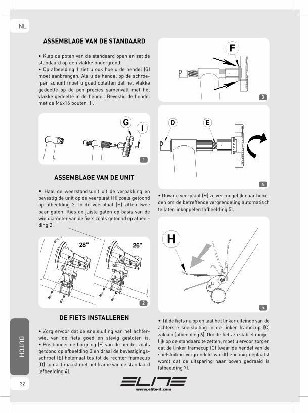
ASSEMBLAGE VAN DE STANDAARD
• Klap de poten van de standaard open en zet de standaard op een vlakke ondergrond.• Op afbeelding 1 ziet u ook hoe u de hendel (G) moet aanbrengen. Als u de hendel op de schroe-fpen schuift moet u goed opletten dat het vlakke gedeelte op de pen precies samenvalt met het vlakke gedeelte in de hendel. Bevestig de hendel met de M6x16 bouten (I).
ASSEMBLAGE VAN DE UNIT
• Haal de weerstandsunit uit de verpakking en bevestig de unit op de veerplaat (H) zoals getoond op afbeelding 2. In de veerplaat (H) zitten twee paar gaten. Kies de juiste gaten op basis van de wieldiameter van de fiets zoals getoond op afbeel-ding 2.
DE FIETS INSTALLEREN
• Zorg ervoor dat de snelsluiting van het achter-wiel van de fiets goed en stevig gesloten is.• Positioneer de borgring (F) van de hendel zoals getoond op afbeelding 3 en draai de bevestigings-schroef (E) helemaal los tot de rechter framecup (D) contact maakt met het frame van de standaard (afbeelding 4).
• Duw de veerplaat (H) zo ver mogelijk naar bene-den om de betreffende vergrendeling automatisch te laten inkoppelen (afbeelding 5).
• Til de fiets nu op en laat het linker uiteinde van de achterste snelsluiting in de linker framecup (C) zakken (afbeelding 6). Om de fiets zo stabiel moge-lijk op de standaard te zetten, moet u ervoor zorgen dat de linker framecup (C) (waar de hendel van de snelsluiting vergrendeld wordt) zodanig geplaatst wordt dat de uitsparing naar boven gedraaid is (afbeelding 7).
GI
F
26"28"
1
2
3
4
5
DU
TCH
NL
32

• Draai de hendel (G) en draai de bevestigings-schroef (E) aan tot de rechter framecup (D) contact maakt met het rechter uiteinde van de snelsluiting (afbeelding 8).
• Vanaf het moment dat de framecup contact maakt met het rechter uiteinde van de snelsluiting draait u de hendel (G) nog een driekwart slag om de fiets stevig aan de standaard vast te zetten. • Zet het bevestigingssysteem vast door de bor-gring (F) van de hendel in de gesloten stand te zetten (afbeelding 9).
• Als het wiel teveel uit het midden op de rol staat maakt u de bevestigingsbouten van de unit (I) los, verplaatst u de unit (afbeelding 10), zet u de unit in de meest geschikte stand en draait u de bouten weer aan.
• Vergewis u ervan dat de fiets goed vast zit in het trainingstoestel door aan de bovenbuis en het zadel te trekken en te duwen. Als de fiets niet stabiel bevestigd is, controleer dan of de snelslui-ting en de betreffende hendel goed gepositioneerd zijn en of de borgring (F) zich in de juiste positie bevindt.• Ontgrendel de veerplaat (H) door de veerplaat met uw handpalm (Y) naar beneden te duwen en met uw vingers de ontgrendehendel (Z) naar boven te trekken (afbeelding 11). Laat de veerplaat (H) rustig naar boven komen tot de rol van de weerstandsunit contact maakt met de fietsband (afbeelding 12).
C
C
D E G
F
6
7
8
129
10
H Y
Z 11
NLD
UTC
H
33

• Bevestig de regelknop op het stuur zoals geto-ond op afbeelding 13 en zorg ervoor dat de kabel aan de binnenkant van de standaard loopt (afbeel-ding 14)
• Bij sturen waarbij u vanwege de diameter van het stuur de klem van de regelknop niet rond het stuur kunt bevestigen, kunt u één of beide rubber tussenrin-gen aan de binnenkant van de klem verwijderen zodat de klem ook op oversized sturen past (afbeelding 15).
• Nu kan er met het trainen begonnen worden waarbij het mogelijk is om de minimum weerstand (waarde 1) tot de maximum weerstand (waarde 5) te veranderen.
DE FIETS VERWIJDEREN
• Maak het fietswiel los, door de veerplaat (H) met uw handpalm naar beneden te duwen tot de ver-grendeling inschakelt (afbeelding 5).• Haal de regelknop van het stuur.• Maak de hendel (G) los door de borgring (F) tegen de hendel (G) aan te duwen (afbeelding 3).• Terwijl u de fiets met uw ene hand vasthoudt draait u met uw andere hand de bevestigings-schroef (E) los en draait u de hendel (G) tot de fiets los is. Verwijder de fiets daarna uit het frame.• Ontgrendel de veerplaat (H) door deze met uw handpalm naar beneden te duwen en met uw vin-gers de ontgrendelhendel naar boven te trekken. Laat de veerplaat (H) zachtjes tot aan het einde van de slag gaan (afbeelding 11).
• Rol de kabel van de regelknop van de weerstan-dsunit voorzichtig op en hang hem over de daartoe bestemde haken aan het trainingstoestel op.
AANDACHTSPUNTEN
• Rem niet tijdens het gebruik van het trainingstoestel; hierdoor kann de rol en de band onherstelbaar beschadigd worden.• De weerstandsunit wordt tijdens gebruik erg heet. Daarom moet u de unit eerst af laten koelen voordat u het vliegwiel aanraakt.• In de weerstandsunit zitten geen onderdelen die los gebruikt kunnen worden. Probeer dan ook niet om de weerstandsunit uit elkaar te schroeven. De garantie vervalt als de unit opengemaakt wordt of als de unit op enige andere wijze gemanipuleerd wordt. • De standaard is gemaakt voor gebruik door één fietser.• Controleer de stabiliteit van de fiets voor u met trai-nen begint.• Aangezien de pootjes van zacht antislip materiaal gemaakt zijn, kan het gebeuren dat de pootjes tijdens het gebruik enkele strepen op de vloer achterlaten.• Als de snelsluiting niet op de framecups van de standaard past moet u de sluiting door de meegele-verde sluiting vervangen (M).
13
14
15
LAAT HET TRAININGSTOESTEL
NOOIT ONBEHEERD ACHTER
MET DE VEERPLAAT IN DE
VERGRENDELDE POSITIE!
DU
TCH
NL
34
GEBRUIKSADVIEZEN
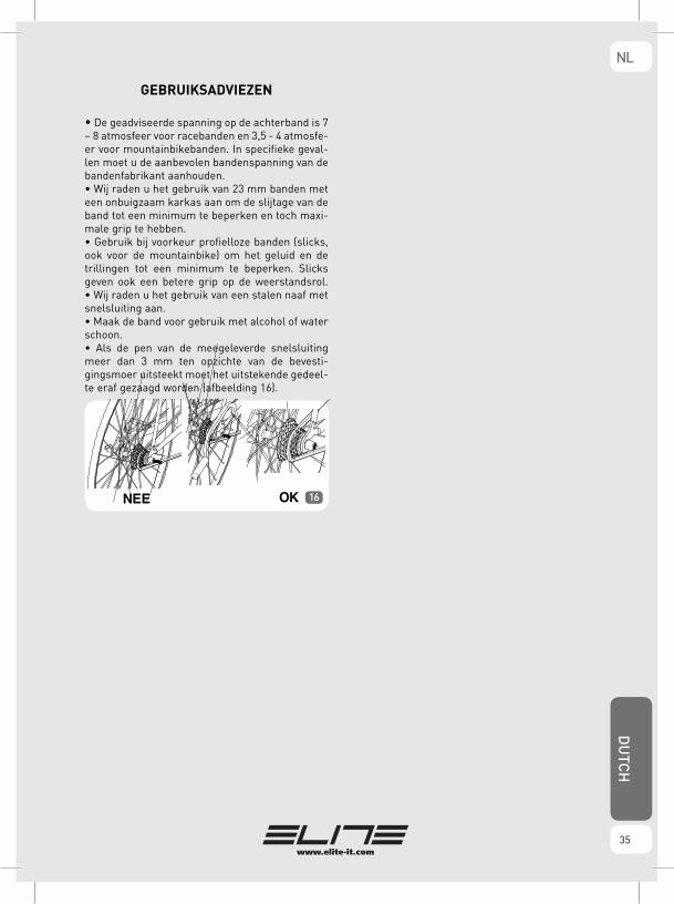
• De geadviseerde spanning op de achterband is 7 – 8 atmosfeer voor racebanden en 3,5 - 4 atmosfe-er voor mountainbikebanden. In specifieke geval-len moet u de aanbevolen bandenspanning van de bandenfabrikant aanhouden.• Wij raden u het gebruik van 23 mm banden met een onbuigzaam karkas aan om de slijtage van de band tot een minimum te beperken en toch maxi-male grip te hebben. • Gebruik bij voorkeur profielloze banden (slicks, ook voor de mountainbike) om het geluid en de trillingen tot een minimum te beperken. Slicks geven ook een betere grip op de weerstandsrol.• Wij raden u het gebruik van een stalen naaf met snelsluiting aan. • Maak de band voor gebruik met alcohol of water schoon.• Als de pen van de meegeleverde snelsluiting meer dan 3 mm ten opzichte van de bevesti-gingsmoer uitsteekt moet het uitstekende gedeel-te eraf gezaagd worden (afbeelding 16).
16
NLD
UTC
H
35

GARANZIA1.In accordo al DL n. 24, del 02/02/2002 e alla direttiva CE 1999/44, ELITE s.r.l. garantisce il proprio prodotto e i materiali impiegati per un periodo di due (2) anni dalla data di acquisto dello stesso.
2.Esclusione della garanzia: per cause diverse da quelle imputabili al costruttore, quali ad esempio negligenza o trascuratezza nell’uso, urti, manutenzioni operate da personale non autorizzato, danni di trasporto, normale usura. Determinano, inoltre, l’esclusione dalla garanzia: l’uso non appropriato allo scopo per cui è stato realizzato il prodotto e l’installazione dello stesso non conforme alle istruzioni fornite da ELITE s.r.l., per i quali, in ogni caso, si declina qualsiasi responsabilità per eventuali danni che ne possano direttamente od indirettamente derivare.
3.Per i prodotti riparati o sostituiti presso la Casa Costruttrice o presso uno dei suoi Centri Assistenza, ELITE s.r.l. non è responsabile di eventuali smar-rimenti o danneggiamenti che avvengano durante il trasporto degli stes-si.
4.Per usufruire del servizio di garanzia è necessario compilare attentamen-te, e per intero, la “CARTA DI ASSISTENZA AL CLIENTE” e di allegarla, assieme ad una copia dello scontrino fiscale o altro documento probante rilasciato dal venditore, che riporti il nominativo dello stesso e la data in cui è stata effettuata la vendita, all’eventuale reso. La mancanza di uno dei suddetti documenti determina l’esclusione dalle condizioni di garanzia.
5.Tutte le informazioni fornite dal consumatore e riportate nella “Carta di assistenza al cliente” verranno trattate in accordo alla norma di cui alla legge 31/12/1996 n°675.
6.Qualora, tra la documentazione allegata al prodotto, sia presente un disegno del prodotto in oggetto, indicare le parti difettose o malfunzio-nanti oggetto del reclamo contrassegnando con una croce i bollini nume-rati presenti sul disegno. Allegare quindi il disegno alla “CARTA DI ASSISTENZA AL CLIENTE”.
7.Elite s.r.l. si riserva il diritto di apportare modifiche tecniche ed estetiche ai propri prodotti senza alcun obbligo di preavviso.
WARRANTY1.In accordance with the law no. 24 of 02/02/2002 and CE directive 1999/44, ELITE s.r.l. guarantees its products and the components used for a period of two (2) years from the date of purchase.
2.Warranty is void for defects caused by reasons not chargeable to the manufacturer such as negligence or carelessness whilst using the product, impacts, maintenance done by non-authorised personnel, damage caused by transportation, normal wear. Additionally, warranty is void in case of improper use of the product, wrong observation of instruction, especially the notice concerning installation and use supplied by ELITE s.r.l. for which in any case it is not responsable for eventual direct or indirect damages.
3.In case of repaired or replaced product done by the Factory or in one of its authorized Service Centers, ELITE s.r.l. is not responsable for any loss or damage during transportation.
4.To take advantage of the warranty service it is necessary to carefully fill in all its parts the “CUSTOMER ASSISTANCE CARD” which needs to accompany, along with the fiscal receipt or other document issued by the Seller which bears the name of the Seller and date selling, the eventual returned product. Warranty is void in case one of these documents are missing.
5.All the information supplied by the Purchaser on the “CUSTOMER ASSISTANCE CARD” will be handled in accordance with the rules of the law no. 675 of 31/12/1996.
6.In case there is, along with the documentation supplied with the pro-duct, a technical drawing of the product itself, indicate the defective or malfunctional part by signing on the correspondant number. The drawing needs to be attached to the “CUSTOMER ASSISTANCE CARD”.
7.ELITE s.r.l. reserves the right to apply technical and aesthetic modifica-tions to its products without obligation of notice.
GARANTIE1.Firma ELITE srl garantiert - gemäß Gesetzesverordnung Nr. 24 vom 02.02.2002 und EG-Richtlinie 1999/44- das eigene Produkt und die für die Herstellung desselben verwendeten Materialien für einen Zeitraum von zwei Jahren ab Anschaffungsdatum.
2.Von dem Garantieanspruch ausgeschlossen sind Schäden, die dem Hersteller nicht zuzuschreiben sind, wie z. B. Fahrlässigkeit und Nachlässigkeit bei der Bedienung und unsachgemässe Behandlung; Schäden, die durch Stösse verursacht werden oder infolge von Wartungsarbeiten auftreten, die von nicht autorisiertem Personal durchgeführt wurden; Transportschäden; normaler Verschleiss. Der Gewährleistungsanspruch verfällt, wenn der Einsatz des Produktes nicht dem Zwecke dient, wofür es hergestellt wurde, und dessen Installation nicht gemäss den Anleitungen von ELITE srl durch-geführt wurde, wofür in jedem Falle jegliche Verantwortung für eventuelle Schäden, die direkt oder indirekt entstehen könnten, abgelehnt wird.
3.ELITE srl ist für den Verlust oder die Beschädigung der Produkte während des Transportes zur Herstellerfirma oder zu einer von ihr eingerichteten Kundendienststelle, wo die Produkte repariert bzw. ersetzt werden, nicht verantwortlich.
4.Die Garantie darf nur beansprucht werden, wenn die “KUNDENDIENSTKARTE” sorgfältig in allen ihren Teilen ausgefüllt und der eventuellen Retourware beigegeben wird – zusammen mit dem Kassabeleg, de Rechnung oder sonstiger Quittung, die vom Verkäufer ausgestellt wurde (darauf müssen Name und Anschrift des Verkäufers sowie das Anschaffungsdatum klar ersichtlich sein). Fehlt eines der hier angeführten Dokumente, verfällt der Garantieanspruch.
5.Alle vom Konsumenten auf der “Kundendienstkarte” angeführten Informationen werden laut den im Gesetz Nr. 675 vom 31.12.1996 festge-schriebenen Normen behandelt.
6.Für den Fall, daß die dem Produkt beiliegende Dokumentation eine Zeichnung des Produktes umfasst, sind die fehlerhaften oder nicht funktio-nierenden Bestandteile, die Gegenstand der Reklamation sind, zu kenn-zeichnen, indem die nummerierten Kreise auf der Zeichnung entsprechend angekreuzt werden. Die Zeichnung ist dann der “KUNDENDIENSTKARTE” beizugeben.
7.ELITE srl behält sich das Recht vor, die eigenen Produkte - ohne Vorankündigung - technisch und optisch zu verbessern.
GARANTIE1.Dans le respect des normatives de la Communauté Européennes, ELITE s.r.l. garantit les propres produits et les matériaux employés pour une pério-de de deux ans (2) à partir de la date d’achat de celui-ci.
2.Exclusions de la garantie: les défauts des produits ELITE S.r.l. créés par des causes diverses de celles imputables au constructeur, comme par exemple la négligence ou le mauvais traitement du produit durant son utilisation, chocs, opérations de manutention effectuées par des personnes non auto-risées, transport, usure normale. Déterminent également l’exclusion de la garantie : l’utilisation non appropriée à la destination pour laquelle le pro-duit a été réalisé et une installation non conforme aux instructions fournies par ELITE s.r.l., et pour lesquels de toute manière, l’on décline toute respon-sabilité pour d’éventuels dommages qui peuvent en dériver directement ou indirectement.
3.Pour les produits réparés ou remplacés par le fabricant ou par un de ses Centres d’Assistance, ELITE s.r.l. n’est pas responsable n’est de pertes éven-tuelles ou dommages intervenus durant le transport.
4.Pour bénéficier du service de garantie, il est nécessaire de remplire comp-lètement et avec précision, la “BON DE GARANTIE DU CLIENT” et de le joindre au produit rendu, avec une copie du reçu de caisse ou tout autre document relâché par le vendeur, indiquant le nom de ce dernier et la data à laquelle a été effectuée la vente. L’absence de l’un de ces docu-ments déterminera l’exclusion des conditions de garantie.
5.Toutes les informations fournies par l’utilisateur et reportées sur le « bon de garantie du client » seront traitées en plein accord avec les normes indiquées par la loi du 31/12/1996 n°675.
6.Si par hasard, dans la documentation jointe au produit rendu, était pré-sent un dessin figurant le produit en objet, indiquer les parties défectueuses ou qui ne fonctionnent pas bien et qui font objet de la réclamation, indi-quant avec une croix les bulles numérotées présentes sur le dessin. Joindre le dessin au “BON DE GARANTIE DU CLIENT ”.
7.ELITE s.r.l. se réserve le droit d’apporter des modifications techniques ou esthétiques à ses propres produits sans aucune obligation de préa-vis.
ITALIANO
ENGLISHFRANÇAIS
DEUTSCH

GARANTIA1.De acuerdo con el DL nº 24 de fecha 02/02/2002 y con la directiva CE 1999/44, ELITE s.r.l. garantiza el propio producto y los materiales emplea-dos por un periodo de dos (2) años a partir de la fecha de compra.
2.Anulación de la garantía: Por causas ajenas no imputables al fabricante tales como negligencia y mal trato durante el uso, robo, mantenimiento efectuado por personal no autorizado, daños de transporte, desgaste normal, etc. Además, la garantía queda anulada por una utilización dife-rente de aquella para la que el producto ha sido concebido y por la insta-lación y montaje del mismo no siguiendo las instrucciones suministradas por Elite s.r.l. por lo que en cada caso se declina todo tipo de responsabilidad para eventuales daños que directa o indirectamente pudieran derivarse.
3.Para los productos reparados o sustituidos por la Casa Constructora o en alguno de sus Centros de Asistencia, Elite s.r.l. no es responsable de even-tuales desperfectos o daños originados durante el transportede los mismos.
4.Para hacer uso del servicio de garantía es necesario cumplimentar aten-tamente y en su totalidad la “CARTA DE ASISTENCIA AL CLIENTE” y de adjuntarla al producto, junto a una copia de la factura u otro documento justificativo emitido por el vendedor en el que se haga constar el nombre y dirección del mismo así como la fecha en la cual ha sido efectuada la venta.
5.Todas las informaciones suministradas por el consumidor e indicadas en la “Carta de Asistencia al cliente” serán tratadas conforme a la normativa incluida en la ley 31/12/1996 nº 675.
6.Cuando, entre la documentación que acompañe al producto, esté pre-sente un diseño del mismo, indicar las partes defectuosas o mal funcionan-tes motivo de la reclamación, marcando con una cruz los cuadros numera-dos presentes en el diseño. Adjuntar por tanto el diseño a la “CARTA DE ASISTENCIA LA CLIENTE”.
7.Elite s.r.l. se reserva el derecho de aportar modificaciones técnicas y de diseño a sus productos sin previo aviso.
GARANTIE1.In overeenkomst met (rechts)artikelnr 24 van 02-02-2002 en CE richtlij-nen, geeft ELITE s.r.l. garantie op haar producten en componenten voor een periode van 2 jaar vanaf het moment van aankoop.
2.Garantie geldt niet voor defecten veroorzaakt door redenen die niet balastbaar zijn aan de fabrikant, zoals nalatigheid of onzorgvuldigheid tijdens het gebruik van het product., stoten/ botsen, handelingen gedaan door niet – geautoriseerd c.q.onprofessioneel personeel, schade door transport of normale slijtage. Bovendien geldt er geen garantie door onge-schikt gebruik van het product, gebruik van verkeerde instructie of obser-vatie, Ook als men de gebruiksaanwijzing voor wat betreft het installeren en gebruik, aangegeven door ELITE s.r.l., niet opvolgt, wordt er in geen geval garantie gegeven aan directe of indirecte schade.
3.In geval van reparatie en/ of vervanging van onderdelen gedaan door de fabrikant, of van een van onze geautoriseerde service centers, is ELITE s.r.l. niet verantwoordelijk voor schade of verlies tijdens transport.
4.Om voor garantie in aanmerking te komen is het van groot belang om alle gegevens op de ‘CUSTOMER ASSISTANCE CARD’ in te vullen. Deze moet samen met een aankoopbon of bewijs, getekend door de verkoper met de gegevens van het product, de aankoopdatum en bedrijf-snaam verstuurd worden. Garantie is niet mogelijk bij het ontbreken van een van deze documenten.
5.Alle informatie, gegeven door de koper op de ‘CUSTOMER ASSISTANCE CARD’ wordt behandeld volgens (rechts)artikelnr. 675 van 31-12-1996.
6.In het geval er een document aanwezig is bij het product met een tech-nische tekening, waar u een indicatie op kunt aangeven wat er defect is, moet u het corresponderende nummer aangeven. De tekening moet samen met de ‘CUSTOMER ASSISTANCE CARD’ card opgestuurd worden
7.ELITE heeft het recht om technische en uiterlijke modificaties bij haar producten aan te brengen, zonder enige verplichte aankondiging.
Mag Speed Gel - Mag Speed Alu - Mag Force Gel 05/2010
ESPAÑOL DUTCH

NOTES

NOTES

NOTES

ELITE srl - 35014 Fontaniva (PD) - ITALY - Fax +39 049 594 0064 - e-mail: [email protected]
cod.
605
4278