
Robotic Book Scanner
19
1 Robotic Book Scanner Elder, Tobias Wong, Cynthia Senior Project Winter-Spring 2014
Transcript of Robotic Book Scanner

1
Robotic Book Scanner
Elder, Tobias
Wong, Cynthia
Senior Project
Winter-Spring 2014

2
Overview
Digitizing books has been an issue tackled by companies to allow people to read off Kindles and iPads
rather than the traditional paperback. Companies like Google have spent more than $1000 on machines
to convert books into electronic copies readable on devices. Yet, not much effort has been made into
the invention of an automatic book scanner for consumers. This project seeks to determine a cost-
effective approach to robotic book scanning to create PDFs from physical books. This project serves as
a proof of concept for a reasonably priced automatic book scanner accessible to consumers.
Potentially, the device may be used in libraries similarly to copy machines where the user pays to have
their book converted to electronic form, however, security measures would need to be made over
access to the PDFs. If developed cost-efficiently enough, consumers may benefit as far as to have the
device in their homes to convert their entire book collections to personal PDFs.
Goal
To develop a proof of concept for an economical robotic book scanner capable of converting books of
any size into PDFs without destroying the binding.
Outcomes and Deliverables
At the completion of this project, we will have created a device that can automatically scan books and
compile them into a PDF file, without any user intervention once the process has been started. The
device will be capable of scanning hard and soft cover books without damaging them.
The final device will consist of a means of turning the book’s pages, a means of photographing each
page, and a system that compiles the photographs into a PDF. The device will be accompanied with
any design references and software needed to replicate it.
Development Process:
For our development process, we decided to use the Waterfall Process, which is the most
straightforward of the generally accepted development processes, and consists of fully realizing and
testing an entire design before attempting a second iteration. The steps of the waterfall process are
detailed below.

3
1. Conception
2. Initiation
3. Analysis
4. Design
5. Construction
6. Testing
7. Production/Implementation
8. Maintenance
Duration
In order to complete the project on time, a schedule was created to keep the team on track, as seen
below in Table 1.
WBS Task description Start date Finish date Assigned To Workdays
1 Prototype Page Turning 3/5/2014 3/9/2014 4
1.1 Gather Materials 3/5/2014 3/8/2014 Both 3
1.2 Test Possible Configurations 3/8/2014 3/9/2014 Both 1
1.3 Benefits/Drawbacks Decision Matrix 3/8/2014 3/9/2014 Both 1
2 Write Report 3/10/2014 3/19/2014 9
2.1 Write Initial Draft 3/10/2014 3/18/2014 Both 8
2.2 Revise to Rough Draft 3/18/2014 3/19/2014 Both 1
3 Acquire Materials 3/5/2014 3/29/2014 24
3.1 Email Yvonne for Funding 3/5/2014 3/6/2014 Both 1
3.2 Create Final Bill of Materials 3/20/2014 3/21/2014 Both 1
3.3 Buy Items Online 3/22/2014 3/23/2014 Both 1
3.4 Shipping and Handling 3/23/2014 3/29/2014 6
4 Assemble Hardware 3/30/2014 4/9/2014 10
4.1 Create Hardware Schematic 3/30/2014 3/31/2014 Both 1
4.2 Assemble Page-Turner 3/31/2014 4/4/2014 Cynthia 4
4.3 Set Up Camera 4/4/2014 4/6/2014 Cynthia 2
4.4 Set Up SD Card Reader 4/6/2014 4/9/2014 Cynthia 3

4
5 Write Software 4/9/2014 4/16/2014 7
5.1 Configure Image Processing 4/9/2014 4/12/2014 Toby 3
5.2 Configure PDF Generation 4/12/2014 4/16/2014 Toby 4
6 System Integration 4/16/2014 4/23/2014 Both 7
7 Test System 4/23/2014 5/7/2014 14
7.1 Acquire Books to Test With 4/23/2014 4/25/2014 Both 2
7.2 Conduct Testing 4/25/2014 4/30/2014 Both 5
7.3 Fix Problems, if any 4/30/2014 5/7/2014 Both 7
8 Write Report 5/7/2014 5/21/2014 14
8.1 Create Second Rough Draft 5/7/2014 5/14/2014 Both 7
8.2 Revise to Final Draft 5/14/2014 5/21/2014 Both 7
9 Make Poster 5/21/2014 5/28/2014 7
Table 1: Project Schedule
Project Requirements and Specifications
Project Requirements:
1) Must be able to scan through an entire book without human intervention (to remedy skipped pages,
fix jams).
2) Must output cropped page images.
3) Images of pages must be rectified and aligned.
4) Output must be collated in a PDF format.
5) Scans must be as readable as the book, with minimal warping or blurriness from page distortion or
camera movement.
6) Device must not damage book in the scanning process.
7) Must be capable of scanning both paperback and hard-cover books
8) Must be capable of scanning books of different page materials.
9) Must be able to be powered by standard NEMA 5-15 wall outlet with 120 Vrms at 60Hz.
Project Specifications:
1) PDF must be at least 150 dpi for readability.
2) Illumination of the pages will be consistent and homogenous across each page and the entire scan.

5
3) Must be capable of scanning a books up to 2.5” thick.
4) Must be capable of scanning books no smaller than 8” x 5”.
5) Must be capable of scanning books no larger than 14” x 14”.
6) Lighting used must be safe for both the user and books, as suggested by NEDCC document
preservation guide.
7) Must be capable of scanning books at least 3 pages per minute.
Research
Before thinking about our own designs, book-scanning devices that other people had built were
researched. The most difficult system to design and construct would be the means of consistently
turning pages, so research was focused on that mechanism. Of the many designs reviewed, most of
them tended to fall into one of 5 general categories in terms of how they turned their pages. Those
methods are detailed below.
1) “Big Finger Little Finger”
Figure 1: “Big Finger Little Finger” System
http://www.diybookscanner.org/forum/viewtopic.php?f=14&t=379&sid=8d40441c6faa8fd35e513c5e4
8444266
Uses one rod with an eraser at the end to push the page (and hopefully separate it) and then another rod
near the spine of the book pushes the page over. And then you take a picture. Book lies in a V.
6
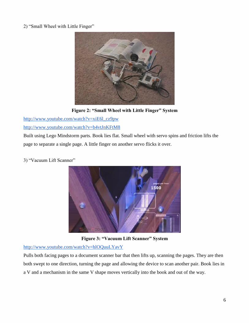
2) “Small Wheel with Little Finger”
Figure 2: “Small Wheel with Little Finger” System
http://www.youtube.com/watch?v=xiE6l_cz9pw
http://www.youtube.com/watch?v=b4vtJnKFtM8
Built using Lego Mindstorm parts. Book lies flat. Small wheel with servo spins and friction lifts the
page to separate a single page. A little finger on another servo flicks it over.
3) “Vacuum Lift Scanner”
Figure 3: “Vacuum Lift Scanner” System
http://www.youtube.com/watch?v=hlOQuuLYavY
Pulls both facing pages to a document scanner bar that then lifts up, scanning the pages. They are then
both swept to one direction, turning the page and allowing the device to scan another pair. Book lies in
a V and a mechanism in the same V shape moves vertically into the book and out of the way.

7
4) “Scissor Vacuum Flipper”
Figure 4: “Scissor Vacuum Flipper” System
http://www.youtube.com/watch?v=XdNdVfPOtko
Two bars flip in opposite directions. A little vacuum close to the edge of the page on the bars pulls
page upright and drops it onto the other bar. Book lies flat.
5) “Page-Thumber”
Figure 5: “Page-Thumber” System
http://www.youtube.com/watch?v=03ccxwNssmo
Presses just on the edge of the book, releasing one page at a time as the mechanical tension of the book
makes each page flip down. Requires a sensor to tell when a page has flipped, in order to take a
picture.

8
Prototyping
Among the various methods researched, three designs for page separation techniques and page turning
techniques were evaluated. Each page separation technique was prototyped and tested at the
midsection of the page, bottom right, and inner mid-section of the page for three books of different
sizes within the specification parameters and page types. Testing was done for pages in the beginning,
middle, and ends of each book. The books were tested both lying flat and at 30 degree angles from the
ground. The three books are listed below:
Books Used for Prototype Testing (L x W x H):
1) 21cm x 13cm x 2.75cm paperback with matte wood free uncoated pages (“Diamond Age” by Neal
Stephenson).
2) 25cm x 21cm x 6 cm hardcover textbook with glossy pages (“Calculus with Selected Problem Sets”
by James Stewart).
3) 27.5 cm x 21 cm x 1 cm paperback with semi-glossy wood free uncoated pages (“Electronic
Gadgets for the Evil Genius” by Bob Iannini).
The mechanical portion of this project has to accomplish two tasks: It must pull the next page in the
book up and away from the subsequent pages, thus separating it from any electrostatic or vacuum force
that was adhering it to the next page, and then it must flip the page and let it settle so that a picture may
be taken.
While it is relatively trivial to get a servo-controlled lever arm under an already separated page in order
to flip it, the separation itself is a tricky task. To that end, we researched other book-scanning solutions
to see how other people accomplished it, and saw that most of the systems fell into one of three
categories:
Page Separation Techniques:
1) Vacuum Suction:
This method would utilize air pressure to lift and separate pages. This technique was done
using wide-bore straws and varying levels of suction from the tester.
2) Mini Rubber Wheel:
A rubber wheel rotates to push the page toward the center, arching it so that a turning
mechanism can get underneath. Testing was done using a 2cm thick, 4cm diameter cylindrical object

9
with rubber bands wrapped around it and was used to approximate a wheel.
3) Eraser:
An eraser pushes the corner of the page upward, arching it so that a turning mechanism can get
underneath. The eraser used for the test was a latex-free Staedtler Mars Plastic drafting eraser.
For all methods, separating the pages was mechanically easiest at the bottom right corner of the pages.
In terms of consistency, the vacuum suction system only lifted one extra page on average, as opposed
to the friction-based techniques which tended to grab extra pages by the dozen. All designs had similar
performance no matter where the page was in the book (beginning, middle, or end) and worked with
all book sizes. The orientation of the book did not affect page separation, however, it is important to
note that the binding was under less stress when the book was tested at a 30 degree angle from the
ground. In terms of safety to the pages, the wheel and eraser would occasionally crease the pages. No
damage was done to pages separated by vacuum.
Page Turning Techniques:
1) Rotating Paddle:
Uses a stick on a servo to sweep across, pushing the page over.
2) Paddle on Rail
Same as Rotating Paddle, but with the stick mounted on a rail instead of a servo.
3) “Scissor” Method
Uses two paddles on articulate servos. Refer to description in Research section 4.
All page turning techniques were simulated using pencils.
Based on the results of the prototype testing, the designs were evaluated in the decision matrix in Table
2 for consistency, ease of construction, ease of use, and versatility. Consistency was ranked as the most
important quality, while ease of use was weighed the least.

10
Page Separation
Techniques
Consistency
Ease of
Construction Ease of Use Versatility Total
Item Weight 10 8 6 8
Vacuum Suction 10 6 8 10 196
Mini Rubber Wheel 4 10 6 2 156
Eraser 4 4 6 4 108
Winner: Vacuum Suction
Page Turning
Techniques
Consistency
Ease of
Construction Ease of Use Versatility Total
Item Weight 10 8 6 8
Rotating Paddle 8 10 10 6 268
Paddle on Rail 8 4 7 7 210
Scissor Method 6 4 6 6 176
Winner: Rotating Paddle
Table 2: Decision Matrix
After comparing the weights of each solution, the top design for page separation techniques was
vacuum suction and the top design for page turning techniques was the rotating paddle.
Design
After deciding which solution to pursue, we determined the parts we would need in the system and the
overall design. To achieve the chosen page separation technique, the system would utilize two servos
and a robotic vacuum. One servo would move the vacuum tube up and down to lift a page and the
other would rotate the paddle to turn the page. The book would be placed in a flat configuration with
the covers held down with clips to allow the rotating paddle to smoothly turn the page. A camera
11
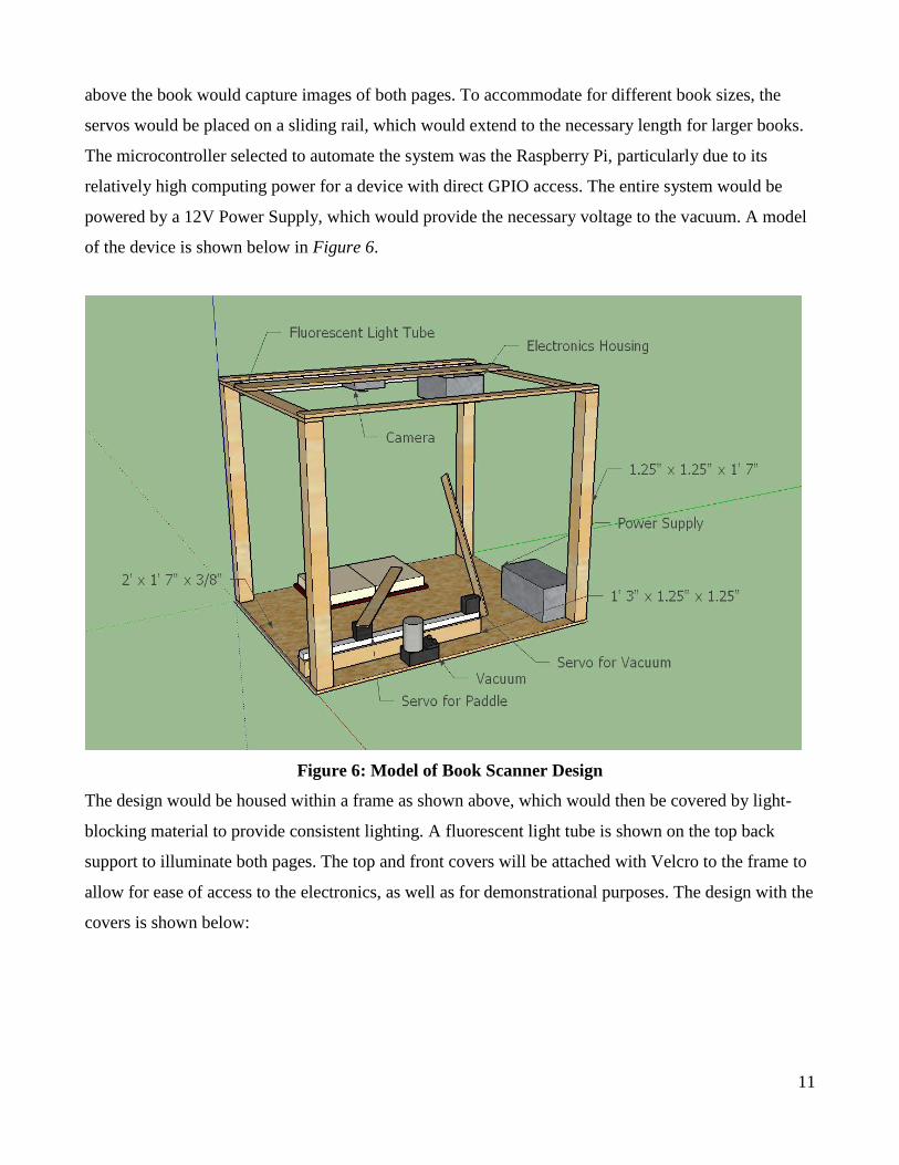
above the book would capture images of both pages. To accommodate for different book sizes, the
servos would be placed on a sliding rail, which would extend to the necessary length for larger books.
The microcontroller selected to automate the system was the Raspberry Pi, particularly due to its
relatively high computing power for a device with direct GPIO access. The entire system would be
powered by a 12V Power Supply, which would provide the necessary voltage to the vacuum. A model
of the device is shown below in Figure 6.
Figure 6: Model of Book Scanner Design
The design would be housed within a frame as shown above, which would then be covered by light-
blocking material to provide consistent lighting. A fluorescent light tube is shown on the top back
support to illuminate both pages. The top and front covers will be attached with Velcro to the frame to
allow for ease of access to the electronics, as well as for demonstrational purposes. The design with the
covers is shown below:

12
Figure 7: Design with Side, Top, and Front Covers
Materials
Because this system is a proof of concept for economically producing a book scanner that could be
accessed by consumers, cost of the materials was crucial. The most costly primary components were
the electronics, taking up about half of the $400 budget.
Primary Materials Cost/Unit Units Supplier
Raspberry Pi Ultimate Camera Kit (includes board, case, SD card,
Raspberry Pi 5MP Camera Board, Wi-Fi card, power supply, and GPIO
breakout board)
$102.99 1 Amazon
16-Channel 12-bit PWM/Servo Driver - I2C Interface $19.20 1 Adafruit
12V Vacuum Pump $14.95 1 Sparkfun
Generic High Torque Servo (Standard Size) $12.95 2 Sparkfun
Standard ATX Compatible Power Supply (no more than 200W needed) $25.00 1 (Salvage)
12” Fluorescent Closet Light $20.99 1 Rite Aid
Power Strip $10.00 1 (Salvage)
$219.03
Table 3: Primary Materials
Although the cost of this project ended up reaching $424.20, many of the components were used in
experimentation to determine the best possible configuration of the system, and did not end up in the

13
final design. The materials that did were wood and nails for the frame (~$50), tubing for the vacuum,
balloon mouth for end of tube to improve suction, blackout curtains and thumbtacks for the covers, an
extendable curtain rod for the sliding rail, large binder clips to hold down the book cover, and a small
box for the electronics housing. These add up to less than $100. Thus, it is a reasonable assumption to
claim that one could make a book scanner for less than $300.
Implementation
The steps taken to construct the design are shown below:
1. Cut, sand, and assemble the wood to create a 2’ x 1’7” x 1’7” frame.
2. Cut an extendable curtain rod to create a sliding rail that is 1’3” when compacted and extends
5” (ensure the outer rail is at least 10.5” long).
3. Mount the rod to a 1.25” x 1.25” wood strut of the same length.
4. Mount the 2 servos on the outer sliding rail approximately 8” from each other (one with the
horn facing up for the paddle and the other with the horn facing out for the vacuum tube).
5. Attach 1’ light-weight wooden pieces to each servo.
6. Mount the robotic vacuum on the floor of the frame about halfway between the servos in their
compacted position.
7. Attach a 1’7” plastic tubing from the vacuum to the wood piece on the appropriate servo with
the tube extending 3” past the piece.
8. Check that the plastic tube lands flat onto the page when the servo is swung downward.
9. Cut the mouth of a balloon and insert it on the end of the plastic tube.
10. Cut and attach light-blocking material to the outsides of the frame using thumbtacks.
11. Attach a longer piece of material that can cover both the top and front of the frame using
Velcro.
12. Mount the fluorescent light tube on the frame at the furthest top strut.
13. Wire the electronics as shown in the pin out in Figure 8.

14
Figure 8: Block Diagram and Pin Out
This diagram illustrates how the components of the design are electrically connected. The Raspberry Pi’s GPIO
module is shown as an attachment because there was a breakout-to-breadboard ribbon cable that allowed easy
access to the board’s GPIO pins.
14. Place the breadboard in an easily accessible housing box, as shown in Figure 9.
15. Attach the Raspberry Pi to the outside of the electronics housing, as shown in Figure 9.
16. Mount the electronics housing such that the camera can reach a position directly above the
book, as shown in Figure 9.
17. Mount the camera above the book, as shown in Figure 9 and Figure 10.

15
Figure 9: Close-up of Electronics Housing and Mounted Camera
Here you can see how the electronics are fastened to the top of the enclosure. The camera was actually rotated
incorrectly; any attempts to replicate our design should have the camera rotated 90 degrees so as to have a
better aspect ratio.
18. Mount the Power Supply on the floor of the frame, as shown in Figure 10.
19. Mount the Power Strip on the back vertical strut, as shown in Figure 10.
20. Program the Raspberry Pi to automate the book scanning process.
Figure 10: Final Assembled Design
This is a front view of the final design. During operation, the blackout curtain around the enclosure will be
covering the front as well, to create a more consistently light environment.

16

17
Programming
The Raspberry Pi is programmed in Python. First, libraries are imported and global variables
initialized.
from Adafruit_PWM_Servo_Driver import PWM import RPi.GPIO as GPIO import picamera from subprocess import call from time import sleep
GPIO.setMode(GPIO.BCM) VACUUM = 18 GPIO.setup(VACUUM, GPIO.OUT)
pwm = PWM(0x40, debug=True)
camera = picamera.PiCamera() camera.resolution = (2592, 1944)
pwm.setPWMFreq(60) servoMin = 150 servoMax = 600
To turn the page, a function was created to direct servos and vacuum output. To control the servos,
pwm.setPWM(servoPin, 0, servoLoc) is called. To control the vacuum pump,
GPIO.output(vacuumPin, onOff) is called. The sleep function must be called between every instruction
to ensure each line is completed during execution.
def runPageTurn(): print "lower arm" pwm.setPWM(SERVO_VAC, 0, 330) sleep(1) GPIO.output(VACUUM, True) sleep(1)
print "reposition paddle" pwm.setPWM(PADDLE, 0, 450) sleep(1)
print "lift page" pwm.setPWM(SERVO_VAC, 0, 435) sleep(3)
print "catch page with flipper" pwm.setPWM(PADDLE, 0, 530) sleep(1)

18
print "drop page" GPIO.output(VACUUM, False) sleep(1) pwm.setPWM(SERVO_VAC, 0, 450) pwm.setPWM(SERVO_VAC, 0, 500)
print "turn page with flipper" pwm.setPWM(PADDLE, 0, 605) sleep(1)
To take pictures, another function was created:
def takePic(): takePic.ndx += 1 camera.capture("output/page{0:04d}.jpg".format(takePic.ndx),
format="jpeg") print("output/page{0:04d}.jpg".format(takePic.ndx)) takePic.ndx = -1;
After all pictures are taken, the images are compiled into a PDF using the lines below:
convertCmd = ['convert', 'output/*.jpg', 'pdf/flipbook.pdf'] call(convertCmd)
A block-diagram flowchart of the code’s scanning procedure is detailed in Figure 11.
Figure 11: Top-level flowchart of book-scanning program.

19
Figure 12: Images from Camera Output
Conclusion
When the system is run, the device can turn 12 pages/minute. Due to the orientation of the book laying
flat, pages turn best for larger books with sturdy bindings. However, if a page or servo arm happens to
catch on something, the interference in either of the servos’ swing path causes the location of the servo
angle to become offset. This can de-synchronize the angle of the page-turning servos and requires
realignment by the user. This happens approximately every 20 page-turns, but can be solved by using
servos that are more mechanically robust. The rotating paddle occasionally leaves small marks in the
bottom of the page, but the pages remain in overall good condition. A thicker, more rounded paddle
could be implemented to prevent damage to the page.
As far as the image output, the camera successfully captures consistently illuminated pages, as seen in
Figure 12. Due to the camera limitations, the resolution could not be improved to the desired DPI and
images could not be cropped or rectified because of the lack of consistent focus across both pages,
causing the right-side page to be more readable than the left. Using two cameras (one for each page) or
obtaining a better camera would remedy this issue. While there are improvements that can be made to
this design, the project successfully served as a proof of concept that the task of robotic book scanning
can be done cost-efficiently for consumers.


![Easy Scan Professional Hornet A0 - avas.nl · Hornet [A0+] semi-robotic High-End large-format scanner … designed for highest requirements The art of scanning: conservational, productive,](https://static.fdocuments.in/doc/165x107/5c02603b09d3f252338df5e9/easy-scan-professional-hornet-a0-avasnl-hornet-a0-semi-robotic-high-end.jpg)