Road Structure Manual for Double Lane Bridges Part-A ... · 9.1 RC deck 1 9.2 RC girder 6 9.3 PC...
177
Web Copy
Transcript of Road Structure Manual for Double Lane Bridges Part-A ... · 9.1 RC deck 1 9.2 RC girder 6 9.3 PC...
Web Copy

ACKNOWLEDGEMENT
We highly appreciate JICA-LGED for undertaking this Road Structures Manual (RSM’08) project for double lane bridges/culverts, including slope protection works, with the objective to strengthen the Design Unit of LGED’s RDEC2 Project. We acknowledge the profound support given in all stages of preparation and finalization of this manual by Mr. Md. Wahidur Rahman, previously Project Director, RDEC2 Project and present Chief Engineer, LGED, JICA representative Mr. Koji Yamada, Chief Project Advisor, RDEC2 Project, and the following other Steering Committee members on behalf of RDEC2, LGED: Mr. Md. Mostadar Rahman, Superintending Engineer-cum-Bridge/Structural Engineer, RDEC2 Project, Mr. Md. Haider Ali, Project Director, Construction of Bridges on Upazila and Union Road Project, Mr. Md. Moksed Alam, Structural Design Engineer, RDEC2 Project, Mr. Md. Mizanur Rahman, Deputy Consultant, CHTRDP, Mr. Md. Zahedul Islam, Assistant Engineer, RDEC2, and Mr. Md. Sarwar Hossain, Design Engineer, Design Unit, RDEC2 Project.
Web Copy
RSM’08
ToC Page i of iii
Road Structures Manual for Double Lane Bridge Part-A Design Criteria, Guidelines and Design Methods for RC/PC Bridges, Box
Culverts and Slope Protection Works
TABLE OF CONTENTS (PART A)
Page No.
Letter of transmittal Abbreviations
CHAPTER 1 INTRODUCTION 1-3 1.1 General 1 1.2 Parts of RSM ’08 1 1.3 Contents of the Manual 2 CHAPTER 2 DEFINITIONS 1-3 CHAPTER 3 PLANNING AND INVESTIGATION 1-8 3.1 General 1 3.2 Criteria for Selection of the type and location of Bridge 1 3.3 General and topographical survey data 2 3.4 Alternative and particular bridge sites 4 3.5 Hydraulic data 4 3.6 Geological data 5 3.7 Climatic data 5 3.8 Loading and other data 5 3.9 Guidelines for providing vertical curves for multiple simple
Span Bridge 6
CHAPTER 4 HYDRAULIC CONSIDERATIONS AND CLEARANCE 1-7 4.1 Design discharge 1 4.2 Linear and effective linear waterway 1 4.3 Effect of presence of dams, weirs, etc. 2 4.4 Spacing and location of piers and abutments 2 4.5 Vertical clearances 3 4.6 Freeboard/navigational clearance 3 4.7 Restricted waterways 3 4.8 Obstruction and river training 4 4.9 Determination of scour depth 4 CHAPTER 5 SUB-SURFACE INVESTIGATION 1-4 5.1 General 1 5.2 Preliminary investigation 1 5.3 Detailed investigation 1 5.4 Exploration for foundations 2
Web Copy

RSM’08
ToC Page ii of iii
Page No. CHAPTER 6 DESIGN CODES, STANDARDS, LOADS, LOAD
FACTORS AND LOAD COMBINATIONS 1-17
6.1 Design codes and standards 1 6.2 Loads 1 6.3 Earth pressure 5 6.4 Effect of shrinkage and creep 8 6.5 Thermal effect 8 6.6 Stream current force on bridge support 8 6.7 Wind load 9 6.8 Due to earthquake load 11 6.9 Curb and railing load 11 6.10 Combination of loads 13 CHAPTER 7 MATERIAL STRENGTH, PROPERTIES AND
QUALITY CONTROL TESTS 1-8
7.1 General 1 7.2 Cement 1 7.3 Fine aggregates 3 7.4 Coarse aggregates 3 7.5 Reinforcing steel 4 7.6 Concrete 5 7.7 Admixture for concrete 7 CHAPTER 8 CONCRETE STRUCTURES 1-15 8.1 General 1 8.2 Definitions 1 8.3 Limit states 8 8.4 Extreme event limit states 12 8.5 Design considerations 12 8.6 Struts-and-tie mdel 12 8.7 Design for flexural and axial force effects 13 8.8 Flexural members 15 CHAPTER 9 SUPERSTRUCTURE 1-38 9.1 RC deck 1 9.2 RC girder 6 9.3 PC girder 11 9.4 Construction and erection of PC girder, deck and railing 25 9.5 Stressing and grouting of PC girder 27 CHAPTER 10 SUBSTRUCTURE OF BRIDGES 1-2 10.1 Design 1 10.2 Construction methodology 4 CHAPTER 11 CAST-IN-PLACE RC PILE FOUNDATION AND PILE
CAP 1-12
11.1 Bored Cast-in-place RCC bored piles 1 11.2 Design of RC pile cap 8
Web Copy

RSM’08
ToC Page iii of iii
CHAPTER 12 REINFORCED ELASTOMERIC BEARING &
EXPANSION JOINT 1-13
12.1 General 1 12.2 Definitions 1 12.3 Steel-reinforced elastomeric bearings 4 12.4 Installation 9 12.5 Expansion joint 12 CHAPTER 13 RC BOX CULVERT 1-6 13.1 Design 1 13.2 Construction 4 CHAPTER 14 SLOPE PROTECTION WORKS 1-35 14.1 Purpose 1 14.2 State-of-the-art practice of slope protection works in
Bangladesh 1
14.3 Slope stability 3 14.4 Design water level, discharge and steam current forces 5 14.5 Wave action and slope stability 6 14.6 Scour 9 14.7 Design of slope protection works 10 14.8 Design of filter 29
Web Copy
Abbreviations
AASHTO American Association of State Highway and Transportation Officials
BNBC’93 Bangladesh National Building Code 1993
GOB Government of Bangladesh
JBIC Japan Bank of International Cooperation
JICA Japan International Cooperation Agency
LGED Local Government Engineering Department
LGRD&C Local Government Rural Development & Cooperatives
PC Prestressed Concrete
RC Reinforced Concrete
RDEC Rural Development Engineering Center
RSM Road Structures Manual
RSM’08 Road Structures Manual, 2008
Web Copy

RSM’08
Chapter 1 Page 1 of 2
CHAPTER 1
1. INTRODUCTION 1.1 General
The LGED under the Ministry of LGRD of GOB have been playing a major role in the rural infrastructure development of Bangladesh. The different infrastructural development projects undertaken by LGED at rural areas are contributing immensely towards the national socio-economic development. To facilitate the construction of the bridges/culverts and the slope protection works for the rural road infrastructures, LGED prepared varieties of Manuals. During 1994 one Road Structures Manual for the reinforced concrete (RC) bridges, culverts and slope protection works was prepared engaging Development Design Consultants (DDC) Ltd. Another Manual on the prestressed concrete bridges was prepared by engaging Design Planning & Management Consultants Ltd. (DPM) during 1996. The structures of the Manual for RC Bridges/Culverts were designed using AASHTO H10/H15/H20 loading; and the structures for the Manual on Prestressed Concrete Bridges were designed using AASHTO HS20-44 loading. For both the above Manuals the carriageway widths were provided for single lane bridges/culverts only.
But during the last decade, rapid industrial and agro-fisheries development has occurred in the rural areas of the country including the Union and village levels. As a result, larger numbers of heavier vehicles are using these rural roads of LGED. Further, the design codes, standards and specifications have been upgraded. Also higher level of awareness on climate change and safety issues has been created.
Therefore, LGED under the sponsorship and support of JICA initiated this project of upgrading the above manuals for dual carriageway brides/culverts. This new Road Structures Manual, 2008, hereinafter called, RSM’08 has been prepared accordingly.
The main objective of this project is to enhance the capacity of the Design Unit of the Rural Development Engineering Center, Phase - 2 (RDEC2) of LGED. 1.2 PARTS OF RSM ’08 This Road Structures Manual for double lane bridges, hereinafter called RSM’08, is presented in 3 parts as follows: 1. Part – A Design criteria, guidelines and design methods
for RC/PC bridges, box culverts and slope protection works
2. Part -B Standard drawings
Volume – I Reinforced concrete bridges Superstructure: RC deck & RC girder Substructure : RC abutment – wing wall Foundation : Cast-in-place bored pile Slope protection works
Web Copy

RSM’08
Chapter 1 Page 2 of 2
Volume – II Prestressed concrete bridges
Superstructure: RC deck & PC girder Substructure : RC abutment – wing wall Foundation : Cast-in-place bored pile
Volume – III Reinforced concrete box culverts
3. Part – C Design examples of bridges, culverts and slope protection works
1.3 CONTENTS OF THE MANUAL This RSM ’08 provides the standard designs of the RC deck girders of span range 12.00 to 25.00 m at an interval of 1.00 m, and of the abutment-wing walls of heights varying between 4.00 m and 8.00 m at an interval of 0.5 m. The carriageway width for the dual carriageway bridge is kept 6,010 mm. Two types of RC decks are provided, namely, Type I with out to out deck width 8,260 mm, and Type II deck with out to out deck width 7,760 mm. Type-I &II deck again may contain either of two types of railings namely, railing type I containing cast-in-place rails giving 875 mm wide sidewalk, and railing type–II containing precast rails giving 625 mm wide sidewalk. Reinforced elastomeric bridge bearings are provided. Return type abutment-wing walls with projected cantilevers/ flags at the wing wall ends containing adequate embedment depth below slope lines are provided. Pile foundation comprising 600 mm diameter bored RC cast-in-place piles are provided.
Mainly, the AASHTO LRFD Bridge Design Specifications, SI Units, 2007, hereinafter called RSM’08, have been followed for the design dead and live loading, and analysis and design of the structures. Bangladesh National Building Code (BNBC’93) has been followed for the environmental loading e.g., winds and earthquake loading. Vehicular live loading on the roadways of bridges/culverts or incidentals have been used: AASHTO designated HL-93, consisting of a combination of design truck or design tandem, and design lane load occurring simultaneously. Structural analysis of the components of the bridge/culverts has been made using STAAD/PRO; laterally loaded piles have been designed using the software PCAColumn. Also excel spreadsheets have been used for preparing the design examples. All drawings are prepared using AutoCAD.
Web Copy

RSM’08
Chapter 2 Page 1 of 3
CHAPTER 2
DEFINITIONS
The following definitions shall be applicable for the purpose of this Manual.
Bridge
Bridge is a structure having an opening not less than 6100 mm for carrying the road traffic or other moving loads over a depression or obstruction such as channel, road or railway.
Box Culvert
It’s a single or multi-cell box shaped drainage structure placed across less defined or undefined channels, or, placed below road embankment for distributed drainage.
Length of a Box Culvert
The length of a box culvert will be taken as the overall length measured along the transverse direction to the traffic direction, measured from the end to end of the box barrel.
Foot Bridge
The foot bridge is a bridge exclusively used for carrying pedestrians, cycles and animals.
Channel
A channel means a natural or artificial water course.
Clearance
Clearance is the shortest distance between boundaries at a specified position of a bridge structure.
Highest Flood Level (HFL)
Highest flood level is the measured or calculated level for the highest possible flood.
Design High Flood Level
Design high flood level corresponds to a HFL against certain return period used for design purpose. For the purpose of this Manual, design HFL shall correspond to 5.0 years return period flood level.
Low Water Level (LWL)
The low water level is the level of the water surface generally obtained in the dry season and it shall be specified in case of each bridge.
Length of a Bridge
The length of a bridge structure will be taken as the overall length measured along the centre-line of the bridge from end to end of the bridge deck.
Web Copy

RSM’08
Chapter 2 Page 2 of 3
Linear Waterway
The linear waterway of a bridge shall be the length available in the bridge between the extreme edges of water surface at the HFL measured at right angles to the abutment faces.
Effective Linear Waterway
Effective linear waterway is the total width of the waterway of the bridge minus the effective width of obstruction.
Load Bearing Abutment
Load bearing abutment is an abutment which supports span of a bridge.
Width of Footpath/Sidewalk
The width of footpath or sidewalk shall be taken as the minimum clear width anywhere within a height of 0.25 meters above the surface of the deck, such width being measured at right angles to the longitudinal centre line of the bridge.
Carriageway
The carriageway width is the minimum clear width measured at right angles to the longitudinal centre line of the bridge between the inside faces of roadway curbs or wheel guards.
Afflux
The rise in the flood level of the river immediately on the upstream of a bridge as a result of obstruction to natural flow caused by the construction of the bridge/culvert and its approaches.
Cofferdam
A structure, usually temporary, built for the purpose of excluding water or soil sufficiently to permit construction or proceed without excessive pumping and to support the surrounding ground.
Foundation
The part of a bridge in direct contract with and transmitting loads to the ground.
Piles
i) Bearing Pile
A pile driven or cast-in-situ for transmitting the weight of a structure to the soil by the resistance developed at the pile base and by friction along its surface. If it supports the load mainly by the resistance developed at its base, it is referred to as an end bearing pile, and if mainly by friction along its surface, it is referred to as a friction pile.
ii) Bored Cast-in-Situ Pile
A pile formed with or without a casing by excavating or boring a hole in the ground and subsequently filling it with plain or reinforced concrete.
Web Copy

RSM’08
Chapter 2 Page 3 of 3
ii) Driven Pile
A pile driven into the ground by the blows of a hammer or by a vibrator.
iv) Driven Cast-in-Place
A pile formed in the ground by driving a permanent or temporary casing, and filling it with plain or reinforced concrete.
v) Precast Pile
A reinforced or prestressed concrete pile cast before driving.
vi) Raker or Batter Pile
A pile installed at an inclination to the vertical.
vii) Sheet Pile
One or a row of piles driven or formed in the ground adjacent to one another in a continuous wall, each generally provided with a connecting joint or inter-lock, designed to resist mainly lateral forces and to reduce seepage; it may be vertical or inclined.
viii) Test Pile
A pile to which load is applied to determine the load/settlement characteristics of the pile and the surrounding ground.
ix) Working Pile
Piles forming the foundation of a structure.
Substructure
The portion of the bridge structure such as piers and abutments above the foundation unit and supporting the superstructure. It shall also include return and wing walls but exclude bearings.
Well Foundation (Caisson)
A structure which is generally built in parts and sunk through ground or water to the prescribed depth and which subsequently becomes an integral part of the permanent foundation.
Caisson/Well Foundation
A caisson is a deep foundation usually circular, elliptical-shaped or, rectangular-shaped with semi-circular/elliptical- shaped nose or any shaped hollow structure placed below abutments/piers caps of the river bridge.
Web Copy
RSM’08
Chapter 3 Page 1 of 8
CHAPTER 3
PLANNING AND INVESTIGATION 3.1 GENERAL Planning and investigation comprise the initial stage activities of the project. The following activities are done at this stage:
• From the preliminary investigation it is ascertained whether a drainage structure is at all required at the proposed site and if required, what type of structure should it be, for example, is it for culvert or for bridge?
• Criteria for selection of the location of the bridge, type of deck e.g., carriageway width, out to out deck width, with or without footpath, RC or PC girders, etc. are decided.
• General data e.g., existing index map and contour survey plans and hydro-meteorological data are collected.
• Topographical survey e.g., preparation of site plan, cross-section surveys are done.
• Alternative and particular bridge sites are selected.
• Geological data for the particular bridge site is collected and assessed.
• Bridge loading and other traffic data are collected.
• Vertical and horizontal clearances of the bridge, hydraulic studies and sub-surface soil investigation are conducted at this stage.
The following sub-sections and the subsequent Chapters 4.0 and 5.0 give detailed guidelines and requirements for obtaining and assessing the above data. 3.2 CRITERIA FOR SELECTION OF THE TYPE AND LOCATION OF BRIDGE
3.2.1 When bridge shall be provided?
Bridges may be categorized as river bridges, overpasses, underpasses, flyovers, etc. This RSM’08 covers the river bridges mainly. The river bridges in general are provided across well defined rivers and channels on the roads.
This Manual contains standard designs of 12.00 m – 25.00 m (c/c bearing) span simply-supported RC bridges, and 20.00 m–40.00 m (c/c bearing) span simply-supported PC bridges.
3.2.2 The criteria for locating the bridges
To locate the Bridge site the following steps/criteria shall be followed:
• Alternative bridge sites shall be identified.
• The location shall preferably be on a straight reach of channel. For a meandered channel it should be located on the crossing between the bends.
Web Copy

RSM’08
Chapter 3 Page 2 of 8
• The approach roads on both sides should be straight for a considerable distance on both banks so that the normal bridge can be provided and bank erosion is negligible.
• The abutments of the bridge should be located on a stable bank.
• In case of proximity of the bridge alignment to the tributary which is the off- take of the channel, the bridge alignment should be located away from the disturbing zone of the off-take channel.
• The bridge location should be such that the deep foundation i.e. piles can be placed in a good bearing strata at a reasonable depth. In case good bearing strata are not available at a reasonable depth, the bridge alignment should be shifted to a suitable alternative location upstream or downstream where good bearing strata is available.
• Otherwise, soil improvement by some suitable method e.g., vibro-compaction for loose granular soil, chemical or cement slurry injection, etc. may be required. For such cases advice of the specialist geotechnical experts should be sought.
3.2.3 Types of deck
Four types of deck are provided for the bridges of this Manual.
Type I with Railing Type I Carriageway width 6010 mm, sidewalk 875 mm, & out to out deck width 8260 mm.
Type I with Railing Type II Carriageway width 6010 mm, sidewalk 750 mm, & out to out deck width 8260 mm.
Type II with Railing Type I Carriageway width 6010 mm, sidewalk 625 mm, & out to out deck width 7760 mm.
Type II with Railing Type II Carriageway width 6010 mm, sidewalk 500 mm, & out to out deck width 7760 mm.
Further details are given in Part B, Standard Drawings, Article 2.0 of this RSM’08. 3.3 GENERAL AND TOPOGRAPHICAL SURVEY DATA
All detailed information (the main items as listed below), shall be provided in the project documents for a complete and proper appreciation of the bridge project.
3.3.1 General data including maps, plans and topographical features a. Index map An index map to a suitable small scale (topographical sheets scale one cm to 500 m or 1/50,000 would do in most cases) showing the proposed location of the bridge, the alternative sites investigated and rejected, the temporary bench marks, the existing means of communications, the general topography of the country, and the important towns, etc., in the vicinity.
Web Copy

RSM’08
Chapter 3 Page 3 of 8
b. Contour survey plan
A contour survey plan of the site and the stream shall be prepared. This will show all topographical features extending upstream and downstream for any of the proposed sites, to the distances shown below, or such other greater distances as the engineer responsible for the design may direct and a sufficient distance on either side to give a clear indication of the topographical or other features that might influence the location and design of the bridge and its approaches. All sites for crossing worth consideration shall be shown on the plan. • 100 m for catchment areas less than 3 square km (scale not less than one cm to 10 m or
1/1000). • 300 m for catchment areas of 3 to 15 square km (scale not less than one cm to 10 m or
1/1000). • One and a half km for catchment areas of more than 15 square km (scale not less than one
cm to 50 m or 1/5000). c. Site plan A site plan to a suitable scale shall be prepared. This will show details of the site selected extending not less than 100 meters both upstream and downstream from the centre line of the crossing and covering the approaches to a sufficient distance which, in the case of a large bridge, shall not be less than 500 m on either side of the channel. The following information shall be indicated on the site plan. • The name of the channel or bridge and of the road and the identification mark allotted to
the crossing, with the location (in kilometers) of the centre of crossing. • The direction of flow of water and maximum discharge and, if possible, the extent of
deviation at lower discharges. • The alignment of existing approaches and of the proposed crossing and its approaches. • The angle and direction of skew if the crossing is aligned on a skew. • The name of the nearest inhabited identifiable locality at either end of the crossing on the
roads leading to the site. • References to the position (with description and reduced level preferably in mPWD) of the
bench mark used as datum. • The lines and identification numbers of the cross section and longitudinal section taken
within the scope of the site plan, and the exact location of their extreme points. • The location of trial pits or borings each being given an identification number and
connected to the datum. • The location of all nalas, buildings, wells, outcrops of rocks, if any and other possible
obstructions, to a road alignment. d. Cross-section survey
Cross-section of the channel at the site of the proposed crossing and two other cross-sections at suitable distances, one upstream and the other downstream, all to the horizontal scale of not less than one cm to 10 m or 1/1000 and with an exaggerated vertical scale of not less than 1 cm to 1 m or 1/100 and indicating the following information shall be prepared: • The bed levels upto the top of banks and the ground levels to a sufficient distance beyond
the edges of the channel, with levels at intervals sufficiently close to give a clear outline of
Web Copy

RSM’08
Chapter 3 Page 4 of 8
markedly uneven features of the bed or ground showing right and left banks and names of villages on each side.
• The nature of the existing surface soil in bed, banks and approaches, and the location and depth of trial pits or borings with their respective identification numbers.
• The highest flood level and the low water level. For tidal streams, the following records of the tidal information, over as long a period as possible, including any local information specific to the site of works shall be collected:
Highest high water (HHW)
Mean high water springs (MHWS)
Mean high water (MHW)
Mean high water neaps (MHWN)
Mean sea level (MSL)
Mean low water (MLW)
Mean low water springs (MLWS) called Chart Datum
Lowest low water (LLW)
• A few cross-sections, in addition to those required, upstream and downstream of the proposed site of the bridge, with both the horizontal and vertical scales being the same as the horizontal scale adopted for the cross-sections required as given above.
• A longitudinal section of the channel, showing the site of the bridge with the highest flood level, the low water level, (also the highest high tide level and the lowest low tide level for tidal channels), and the bed levels at suitably spaced intervals along the approximate centre-line of the deep water channel between the approximate points to which the survey plan as given above extends. The horizontal scale shall be the same as for the survey plan and the vertical scale not less than one cm to 10 m or 1/1000.
3.4 ALTERNATIVE AND PARTICULAR BRIDGE SITES
A brief description of the reasons for selection of a particular site for the crossing accompanied, if necessary, with typical cross-sections of the channel at alternative sites investigated and rejected. 3.5 HYDRAULIC DATA
• The size, shape and surface characteristics of the catchment including percolation and interception.
• The possibility of subsequent changes in the catchment like afforestation, deforestation, urban development, extension of or deduction in cultivated area, etc.
• Storage in the catchment, artificial or natural.
• The intensity and frequency of rainfall in the catchment.
Web Copy

RSM’08
Chapter 3 Page 5 of 8
• The slope of the catchment, both longitudinal and cross directional.
• Hydrographs for one or more years, if possible, and in the absence of such data, fluctuations of the water level observed during different months of the year.
• The highest flood level and the year of its occurrence. If the flood level is affected by backwater, details of the same.
• A chart of the periods of high flood levels for as many years as the relevant data has been recorded.
• The influence of afflux on areas in the vicinity likely to be affected.
• Low water level.
• The design discharge, the linear waterway and corresponding average velocity of flow.
• The observed maximum depth of scour with corresponding level and details of obstruction or any other special causes responsible for the scour.
3.6 GEOLOGICAL DATA • The nature and properties of the existing soil in bed, banks and approaches.
• Susceptibility of the site to earthquake disturbances and its magnitude.
3.7 CLIMATIC DATA
Information regarding usual annual temperature range, susceptibility to severe storms, cyclones, etc., and probable wind velocity, rainfall characteristics indicating period of rainy seasons, relative humidity and salinity or presence of harmful chemicals in the atmosphere shall be collected.
3.8 LOADING AND OTHER DATA
• The bridge will be designed for the live load as per relevant Articles of AASHTO Standard Specifications for Highway Bridges, 2007. Any specific variation from those clauses, if required, shall be covered by special load conditions.
• Special local conditions, like traffic intensity and pattern to enable the designer to fix the loading to be adopted for the footpath and to fix deck types required.
• Utilities or services, if any, to be provided for and if so nature thereof (e.g. telephone cables, water supply pipes, gas pipes, etc.) and relevant information regarding size, arrangement, etc.
• The minimum vertical and horizontal clearances required for any special requirement like, navigation, rising of the bed, etc., and the basis on which it is suggested.
• An index map showing location of rail and road bridges, if any, crossing the same channel or its tributaries within a reasonable distance of the proposed bridge and a note (with sketches or drawings) giving important details of such bridges.
• A note stating whether large trees and rolling debris, etc. are likely to float down the channel at the proposed bridge site.
• Any other additional information which may be considered essential for complete and proper appreciation of the project.
Web Copy
RSM’08
Chapter 3 Page 6 of 8
3.9 GUIDELINES FOR PROVIDING VERTICAL CURVES FOR MULTIPLE SIMPLE SPAN BRIDGE
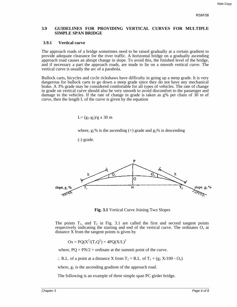
3.9.1 Vertical curve
The approach roads of a bridge sometimes need to be raised gradually at a certain gradient to provide adequate clearance for the river traffic. A horizontal bridge on a gradually ascending approach road causes an abrupt change in slope. To avoid this, the finished level of the bridge, and if necessary a part the approach roads, are made to lie on a smooth vertical curve. The vertical curve is usually the arc of a parabola.
Bullock carts, bicycles and cycle rickshaws have difficulty in going up a steep grade. It is very dangerous for bullock carts to go down a steep grade since they do not have any mechanical brake. A 3% grade may be considered comfortable for all types of vehicles. The rate of change in grade on vertical curve should also be very smooth to avoid discomfort to the passenger and damage to the vehicles. If the rate of change in grade is taken as g% per chain of 30 m of curve, then the length L of the curve is given by the equation
L= (g1-g2)/g x 30 m
where, g1% is the ascending (+) grade and g2% is descending
(-) grade.
Fig. 3.1 Vertical Curve Joining Two Slopes
The points T1, and T2 in Fig. 3.1 are called the first and second tangent points respectively indicating the starting and end of the vertical curve. The ordinates Ox at distance X from the tangent points is given by
Ox = PQ(X2/(T1Q2) = 4PQ(X/L)2 where, PQ = PN/2 = ordinate at the summit point of the curve.
:. R.L. of a point at a distance X from T1 = R.L. of T1 + (g1 X/100 - Ox)
where, g1 is the ascending gradient of the approach road.
The following is an example of three simple span PC girder bridge.
Web Copy
RSM’08
Chapter 3 Page 7 of 8
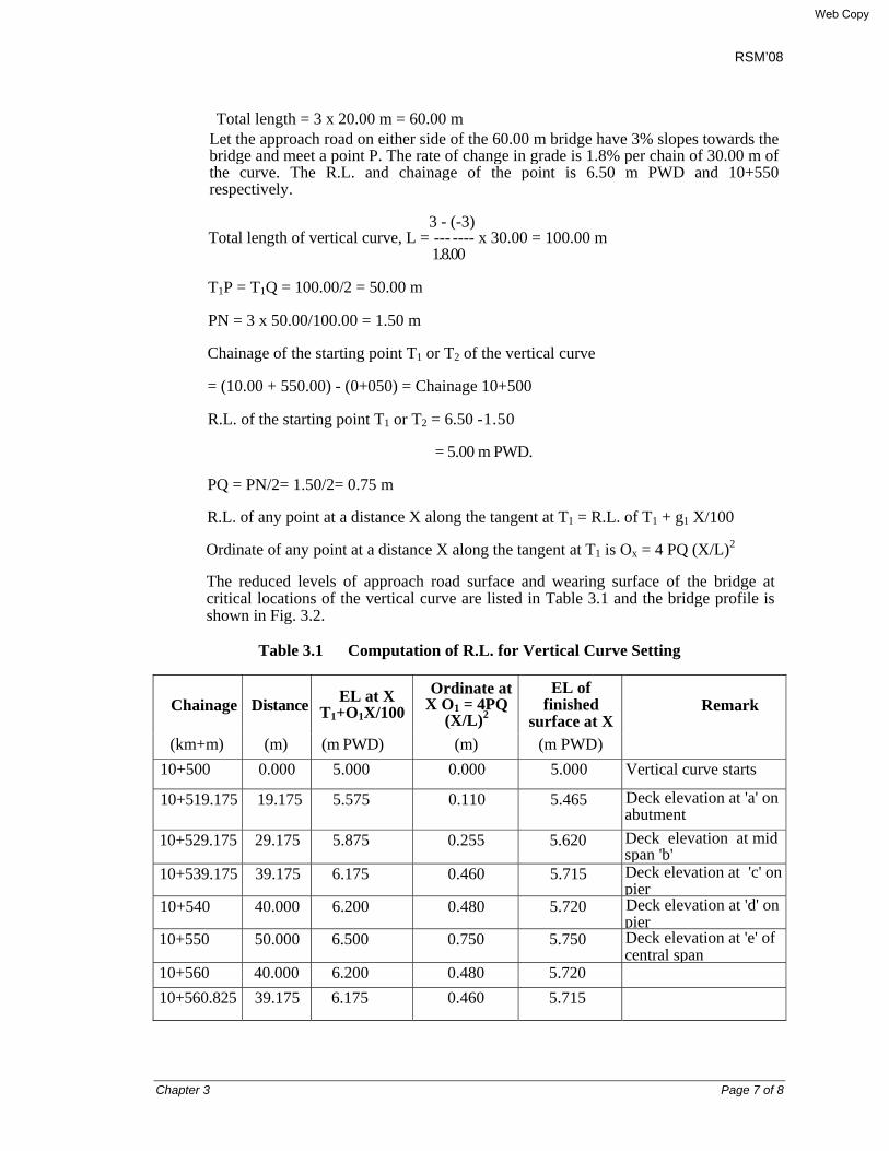
Total length = 3 x 20.00 m = 60.00 m Let the approach road on either side of the 60.00 m bridge have 3% slopes towards the bridge and meet a point P. The rate of change in grade is 1.8% per chain of 30.00 m of the curve. The R.L. and chainage of the point is 6.50 m PWD and 10+550 respectively.
3 - (-3) Total length of vertical curve, L = --- ---- x 30.00 = 100.00 m
1.8.00
T1P = T1Q = 100.00/2 = 50.00 m
PN = 3 x 50.00/100.00 = 1.50 m
Chainage of the starting point T1 or T2 of the vertical curve
= (10.00 + 550.00) - (0+050) = Chainage 10+500
R.L. of the starting point T1 or T2 = 6.50 -1.50
= 5.00 m PWD.
PQ = PN/2= 1.50/2= 0.75 m
R.L. of any point at a distance X along the tangent at T1 = R.L. of T1 + g1 X/100
Ordinate of any point at a distance X along the tangent at T1 is Ox = 4 PQ (X/L)2
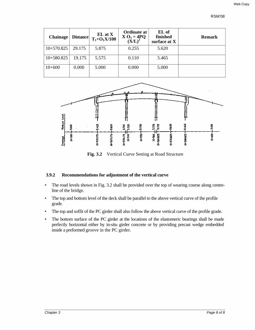
The reduced levels of approach road surface and wearing surface of the bridge at critical locations of the vertical curve are listed in Table 3.1 and the bridge profile is shown in Fig. 3.2.
Table 3.1 Computation of R.L. for Vertical Curve Setting
Chainage Distance EL at X T1+O1X/100
Ordinate at X O1 = 4PQ
(X/L)2
EL of finished
surface at XRemark
(km+m) (m) (m PWD) (m) (m PWD) 10+500 0.000 5.000 0.000 5.000 Vertical curve starts
10+519.175 19.175 5.575 0.110 5.465 Deck elevation at 'a' on abutment
10+529.175 29.175 5.875 0.255 5.620 Deck elevation at mid span 'b'
10+539.175 39.175 6.175 0.460 5.715 Deck elevation at 'c' on pier
10+540 40.000 6.200 0.480 5.720 Deck elevation at 'd' on pier
10+550 50.000 6.500 0.750 5.750 Deck elevation at 'e' of central span
10+560 40.000 6.200 0.480 5.720 10+560.825 39.175 6.175 0.460 5.715
Web Copy
RSM’08
Chapter 3 Page 8 of 8
Chainage Distance EL at X T1+O1X/100
Ordinate at X O1 = 4PQ
(X/L)2
EL of finished
surface at XRemark
10+570.825 29.175 5.875 0.255 5.620
10+580.825 19.175 5.575 0.110 5.465
10+600 0.000 5.000 0.000 5.000
Fig. 3.2 Vertical Curve Setting at Road Structure
3.9.2 Recommendations for adjustment of the vertical curve
• The road levels shown in Fig. 3.2 shall be provided over the top of wearing course along centre-line of the bridge.
• The top and bottom level of the deck shall be parallel to the above vertical curve of the profile grade.
• The top and soffit of the PC girder shall also follow the above vertical curve of the profile grade.
• The bottom surface of the PC girder at the locations of the elastomeric bearings shall be made perfectly horizontal either by in-situ girder concrete or by providing precast wedge embedded inside a preformed groove in the PC girder.
Web Copy
RSM’08
Chapter 4 Page 1 of 7
CHAPTER 4
HYDRAULIC CONSIDERATIONS AND CLEARANCE 4.1 DESIGN DISCHARGE The design discharge for which the waterway of the bridge is to be designed, shall be the maximum flood discharge on record or the estimated maximum discharge for a period of not less than 50 years. In case where the requisite information is not available, the design discharge shall be the maximum estimated discharge determined by consideration of the following; or, any rational method.
a) From the available records, if any, of observed discharge on the stream at the site of the bridge, or at any other site in its vicinity.
b) From the rainfall and other characteristics of the catchments:
i) By using an empirical formula applicable to that region, or
ii) By a recognized method, provided i t is possible to evaluate the various factors employed in that method for the region concerned.
c) By the area velocity method with the help of hydraulic characteristics of the channel.
d) Where possible, more than one method shall be adopted, results will be compared, and the maximum discharge will be fixed by judgment of the engineer responsible for the design. The bridge shall be designed for this maximum discharge.
Peak flood discharges e.g., exceptional discharges due to the failure of a dam constructed upstream to the bridge need not be catered for, and the maximum estimated discharge from the catchment area should be considered for design of the bridge/culverts. 4.2 LINEAR AND EFFECTIVE LINEAR WATERWAY For artificial channels (irrigation, navigation and drainage), the effective linear waterway shall generally be such as to pass the full discharge at normal velocity but concurrence shall invariably be obtained from the authority controlling the channel. If it is proposed to flume/constrict the channel at the site of the bridge, this fluming shall be subject to the consent of the same authority and in accordance with the essential requirements. For non-meandering channels in alluvial beds with well-defined banks and for all natural channel beds with rigid nonerodible boundaries, the linear waterway shall be the distance between banks at that water surface elevation, at which the designed maximum discharge determined can be passed without creating harmful afflux. For natural channels in alluvial beds and having undefined banks, the effective linear waterway shall be determined from the design discharge, using some accepted rational formula at the discretion of the engineer responsible for the design. One such formula for regime conditions is:
Web Copy

RSM’08
Chapter 4 Page 2 of 7
W = C√Q
where, W = regime width in meters (equal to effective linear waterway under regime conditions)
Q = the design maximum discharge in m3 /sec; C = a constant usually taken as 4.8 for regime channels but it may vary from
4.5 to 6.3 according to local conditions If the river is of flashy nature and the bed does not subject readily to the scouring effects of the flood, the waterway should be determined by the area-velocity method taking into account the design flood level and the characteristics of the bed material as well as water surface slope (ref: Article 5.8 of this Manual). Where it is decided to adopt measures which are likely to affect the volume of the tidal flow and other characteristics of the tide, it shall be ensured that no port or harbor or other installations in the proximity of the bridge is adversely affected. For calculating the effective linear waterway, the width of obstruction due to pier(s), if any, shall be taken as the mean submerged width of the pier and its foundation up to the mean scour level. The obstruction at the ends due to the abutments or pitched slopes shall be ignored. 4.3 EFFECT OF PRESENCE OF DAMS, WEIRS, ETC. Presence of dams, barrages, weirs, etc. on the rivers affects the hydraulic characteristics of the rivers like obliquity and concentration of flow, scour, silting of bed, change in bed levels, flood levels, etc. These effects shall be considered in the design of bridges depending upon whether the proposed site of the bridge is at upstream or downstream of the dam or, barrage or, weir. Since the above parameters depend on many factors which are varying from site to site, no uniform guidelines can possibly be laid down. Such problems should be jointly taken up with the concerned Departments and suitable provisions must be made in the bridge design. 4.4 SPACING AND LOCATION OF PIERS AND ABUTMENTS Piers and abutments shall be so located as to make the best use of the foundation conditions available. Keeping this in view, the number of supports and their locations shall be so fixed as to provide the most economical design of the bridge and at the same time satisfy special requirements, if any, for navigation, drift timber, railway or other crossing and aesthetics, etc. The alignment of the piers and abutments shall, as far as possible, be parallel to the mean flow direction of in the channel but provision shall be made against harmful effects on the stability of the bridge structure and on the maintenance of adjacent channel banks caused by any temporary variations in the direction and velocity of the current.
Web Copy
RSM’08
Chapter 4 Page 3 of 7
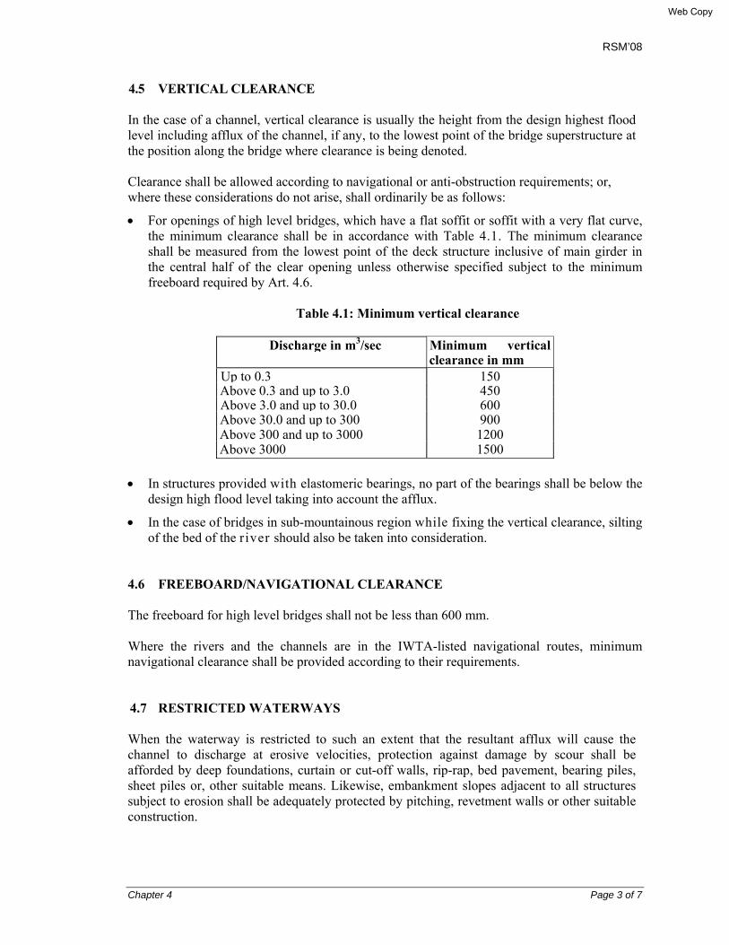
4.5 VERTICAL CLEARANCE In the case of a channel, vertical clearance is usually the height from the design highest flood level including afflux of the channel, if any, to the lowest point of the bridge superstructure at the position along the bridge where clearance is being denoted. Clearance shall be allowed according to navigational or anti-obstruction requirements; or, where these considerations do not arise, shall ordinarily be as follows:
• For openings of high level bridges, which have a flat soffit or soffit with a very flat curve, the minimum clearance shall be in accordance with Table 4.1. The minimum clearance shall be measured from the lowest point of the deck structure inclusive of main girder in the central half of the clear opening unless otherwise specified subject to the minimum freeboard required by Art. 4.6.
Table 4.1: Minimum vertical clearance
Discharge in m3/sec Minimum vertical
clearance in mm Up to 0.3 150Above 0.3 and up to 3.0 450Above 3.0 and up to 30.0 600Above 30.0 and up to 300 900Above 300 and up to 3000 1200Above 3000 1500
• In structures provided with elastomeric bearings, no part of the bearings shall be below the
design high flood level taking into account the afflux.
• In the case of bridges in sub-mountainous region while fixing the vertical clearance, silting of the bed of the river should also be taken into consideration.
4.6 FREEBOARD/NAVIGATIONAL CLEARANCE The freeboard for high level bridges shall not be less than 600 mm. Where the rivers and the channels are in the IWTA-listed navigational routes, minimum navigational clearance shall be provided according to their requirements. 4.7 RESTRICTED WATERWAYS When the waterway is restricted to such an extent that the resultant afflux will cause the channel to discharge at erosive velocities, protection against damage by scour shall be afforded by deep foundations, curtain or cut-off walls, rip-rap, bed pavement, bearing piles, sheet piles or, other suitable means. Likewise, embankment slopes adjacent to all structures subject to erosion shall be adequately protected by pitching, revetment walls or other suitable construction.
Web Copy
RSM’08
Chapter 4 Page 4 of 7
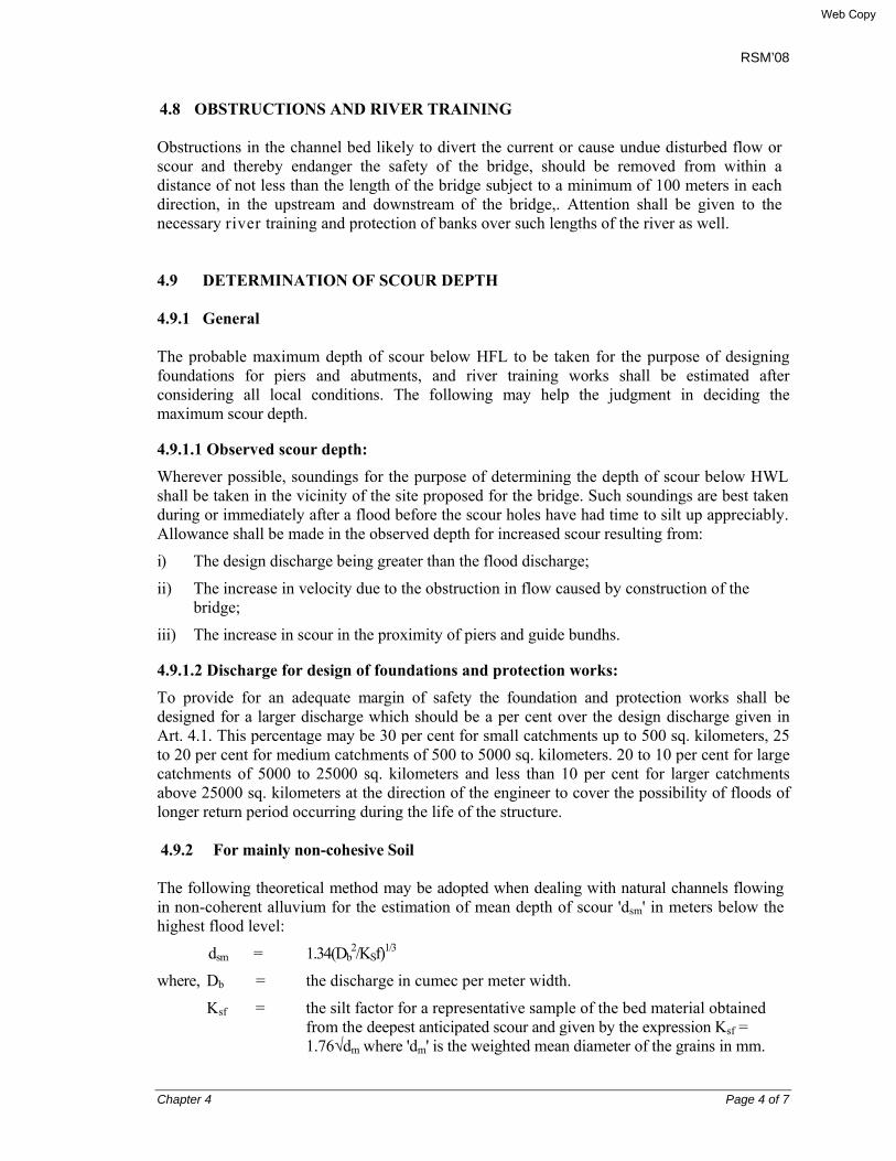
4.8 OBSTRUCTIONS AND RIVER TRAINING Obstructions in the channel bed likely to divert the current or cause undue disturbed flow or scour and thereby endanger the safety of the bridge, should be removed from within a distance of not less than the length of the bridge subject to a minimum of 100 meters in each direction, in the upstream and downstream of the bridge,. Attention shall be given to the necessary river training and protection of banks over such lengths of the river as well. 4.9 DETERMINATION OF SCOUR DEPTH 4.9.1 General The probable maximum depth of scour below HFL to be taken for the purpose of designing foundations for piers and abutments, and river training works shall be estimated after considering all local conditions. The following may help the judgment in deciding the maximum scour depth.
4.9.1.1 Observed scour depth:
Wherever possible, soundings for the purpose of determining the depth of scour below HWL shall be taken in the vicinity of the site proposed for the bridge. Such soundings are best taken during or immediately after a flood before the scour holes have had time to silt up appreciably. Allowance shall be made in the observed depth for increased scour resulting from:
i) The design discharge being greater than the flood discharge;
ii) The increase in velocity due to the obstruction in flow caused by construction of the bridge;
iii) The increase in scour in the proximity of piers and guide bundhs.
4.9.1.2 Discharge for design of foundations and protection works:
To provide for an adequate margin of safety the foundation and protection works shall be designed for a larger discharge which should be a per cent over the design discharge given in Art. 4.1. This percentage may be 30 per cent for small catchments up to 500 sq. kilometers, 25 to 20 per cent for medium catchments of 500 to 5000 sq. kilometers. 20 to 10 per cent for large catchments of 5000 to 25000 sq. kilometers and less than 10 per cent for larger catchments above 25000 sq. kilometers at the direction of the engineer to cover the possibility of floods of longer return period occurring during the life of the structure. 4.9.2 For mainly non-cohesive Soil The following theoretical method may be adopted when dealing with natural channels flowing in non-coherent alluvium for the estimation of mean depth of scour 'dsm' in meters below the highest flood level:
dsm = 1.34(Db2/KSf)1/3
where, Db = the discharge in cumec per meter width.
Ksf = the silt factor for a representative sample of the bed material obtained from the deepest anticipated scour and given by the expression Ksf = 1.76√dm where 'dm' is the weighted mean diameter of the grains in mm.
Web Copy
RSM’08
Chapter 4 Page 5 of 7
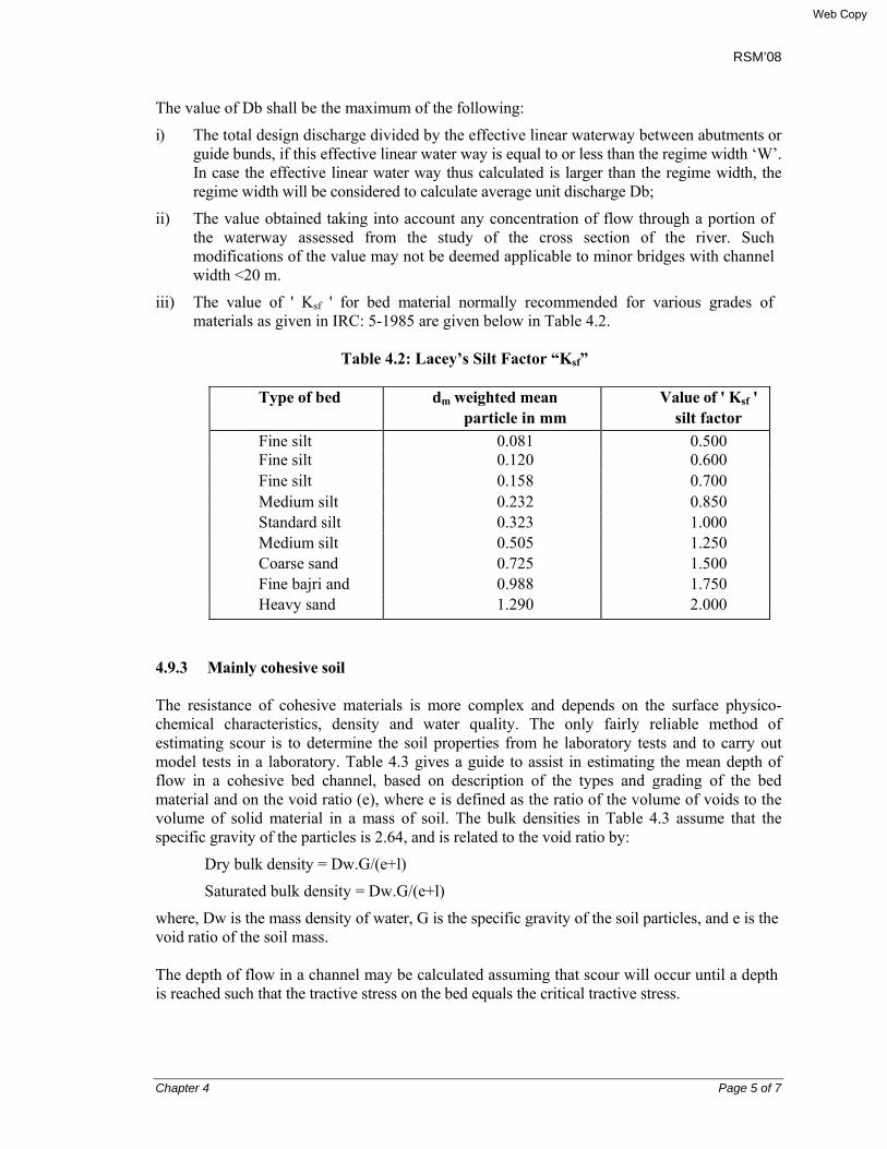
The value of Db shall be the maximum of the following:
i) The total design discharge divided by the effective linear waterway between abutments or guide bunds, if this effective linear water way is equal to or less than the regime width ‘W’. In case the effective linear water way thus calculated is larger than the regime width, the regime width will be considered to calculate average unit discharge Db;
ii) The value obtained taking into account any concentration of flow through a portion of the waterway assessed from the study of the cross section of the river. Such modifications of the value may not be deemed applicable to minor bridges with channel width <20 m.
iii) The value of ' Ksf ' for bed material normally recommended for various grades of materials as given in IRC: 5-1985 are given below in Table 4.2.
Table 4.2: Lacey’s Silt Factor “Ksf”
Type of bed dm weighted mean Value of ' Ksf ' particle in mm silt factor Fine silt 0.081 0.500 Fine silt 0.120 0.600 Fine silt 0.158 0.700 Medium silt 0.232 0.850 Standard silt 0.323 1.000 Medium silt 0.505 1.250 Coarse sand 0.725 1.500 Fine bajri and 0.988 1.750 Heavy sand 1.290 2.000
4.9.3 Mainly cohesive soil The resistance of cohesive materials is more complex and depends on the surface physico-chemical characteristics, density and water quality. The only fairly reliable method of estimating scour is to determine the soil properties from he laboratory tests and to carry out model tests in a laboratory. Table 4.3 gives a guide to assist in estimating the mean depth of flow in a cohesive bed channel, based on description of the types and grading of the bed material and on the void ratio (e), where e is defined as the ratio of the volume of voids to the volume of solid material in a mass of soil. The bulk densities in Table 4.3 assume that the specific gravity of the particles is 2.64, and is related to the void ratio by:
Dry bulk density = Dw.G/(e+l)
Saturated bulk density = Dw.G/(e+l)
where, Dw is the mass density of water, G is the specific gravity of the soil particles, and e is the void ratio of the soil mass. The depth of flow in a channel may be calculated assuming that scour will occur until a depth is reached such that the tractive stress on the bed equals the critical tractive stress.
Web Copy
RSM’08
Chapter 4 Page 6 of 7
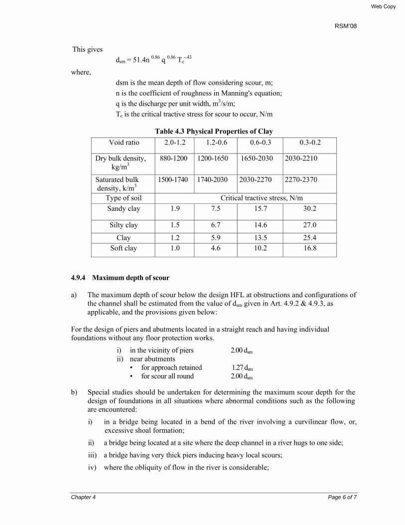
This gives dsm = 51.4n 0.86 q 0.86 Tc
-.43
where, dsm is the mean depth of flow considering scour, m; n is the coefficient of roughness in Manning's equation; q is the discharge per unit width, m3/s/m; Tc is the critical tractive stress for scour to occur, N/m
Table 4.3 Physical Properties of Clay
4.9.4 Maximum depth of scour a) The maximum depth of scour below the design HFL at obstructions and configurations of
the channel shall be estimated from the value of dsm given in Art. 4.9.2 & 4.9.3, as applicable, and the provisions given below:
For the design of piers and abutments located in a straight reach and having individual foundations without any floor protection works.
i) in the vicinity of piers 2.00 dsm ii) near abutments
• for approach retained 1.27 dsm • for scour all round 2.00 dsm
b) Special studies should be undertaken for determining the maximum scour depth for the design of foundations in all situations where abnormal conditions such as the following are encountered:
i) in a bridge being located in a bend of the river involving a curvilinear flow, or, excessive shoal formation;
ii) a bridge being located at a site where the deep channel in a river hugs to one side;
iii) a bridge having very thick piers inducing heavy local scours;
iv) where the obliquity of flow in the river is considerable;
Void ratio 2.0-1.2 1.2-0.6 0.6-0.3 0.3-0.2
Dry bulk density, kg/m3
880-1200 1200-1650 1650-2030 2030-2210
Saturated bulk density, k/m3
1500-1740 1740-2030 2030-2270 2270-2370
Type of soil Critical tractive stress, N/m Sandy clay 1.9 7.5 15.7 30.2
Silty clay 1.5 6.7 14.6 27.0
Clay 1.2 5.9 13.5 25.4 Soft clay 1.0 4.6 10.2 16.8
Web Copy
RSM’08
Chapter 4 Page 7 of 7
v) where a bridge is required to be constructed across a canal, or across a river downstream of storage works, with the possibility of the relatively clear water inducing greater scours;
vi) a bridge in the vicinity of a dam, weir, barrage or other irrigation structures where concentration of flow, aggradations/degradation of bed, etc. are likely to affect the behavior of the structure.
c) If a river is of flashy nature and the bed does not lend itself readily to the scouring effect of floods, the formula for dsm given in Art. 4.9.2 & 4.9.3 shall not apply. In such cases, the maximum depth of scour shall be assessed from actual observations.
d) For bridges located across streams having boulder beds, there is yet no rational formula for determining scour depth. However, the formula given in Art. 4.9.2 & 4.9.3 may be applied, with a judicious choice of values for 'Db' and 'KS’ (and the results compared with the actual observations at site or from experiences on similar structures nearby and their performance. If a pucca floor at bed is provided, in such cases, it is essential to check the hydraulic performance of these structures under various flow conditions to ensure that a standing wave is not formed on the downstream side which may result in very heavy scours. It is also essential to check the usual scour that may take place downstream of bed flooring and to make adequate provision for the same. If it is not possible to increase the waterway and to avoid the formation of a standing wave, a depressed pucca floor on the downstream may be provided to contain the standing wave within the floor.
Web Copy

RSM’0
Chapter 5 Page 1 of 4
CHAPTER 5
SUB-SURFACE INVESTIGATION
5.1 GENERAL The sub-surface investigation is required at the initial stage of the project with the objective to determine the suitability of the sub-soil for the foundation of the bridges. This sub-surface investigation can be carried out in two stages, namely, preliminary and detailed. 5.2 PRELIMINARY INVESTIGATION Preliminary investigation shall include the study of existing geological information, previous site reports, geological maps, air photos, etc. and surface geological examination. In case of important bridge where no previous sub-surface data are available a few bore-holes may be taken. These will help to narrow down the number of sites under consideration and also to locate the most desirable site at which detailed sub-surface investigation like bore or drill holes, etc. are to be conducted. 5.3 DETAILED INVESTIGATION 5.3.1 Scope Based on data obtained after preliminary investigation of the bridge site, the type of structure with span arrangement, the location and type of foundation, the program of detailed investigation, etc. shall be decided. Thereafter the scope of detailed investigation including the extent of exploration, number of bore holes, type of tests, number of tests, etc. shall be decided in close liaison with the design engineer and the exploration team, so that adequate data necessary for detailed design and execution are obtained. For the bridges of this manual the number of bore-holes should be at least one below each abutment foundation. 5.3.2 Extent of boring Generally the sub-surface investigation should extend to a depth below the anticipated foundation level equal to about one and a half times the width of the foundation; in case of pile foundation the width of pile group shall be considered as the width of foundation. However, where such investigation ends in any unsuitable or questionable foundation material, the exploration shall be extended to a sufficient depth into firm and stable soils.
5.3.2.1 Location of boring
Where the data made available by detailed exploration indicates appreciable variation or where such variations in a particular foundation, are likely to appreciably affect the construction, it will be necessary to resort to additional bore to establish a complete profile of the underlying strata. The requirement of additional boring will be decided depending upon the extent of variation at a particular foundation location and should cover the entire area of the particular foundation and be decided in consultation with the design engineer.
Web Copy

RSM’0
Chapter 5 Page 2 of 4
5.3.2.2 Construction stage exploration
Such exploration may become necessary when a change in the sub-soil strata is encountered during construction. In such situations it may be essential to resort to further exploration to establish the correct data, for further decision. 5.3.3 Sub-surface data required The scope of the detailed sub-surface exploration shall be decided as mentioned in Art. 5.3.1 and 5.3.2. However, as a general guide it shall be comprehensive enough to enable the designer to estimate or determine the following:
i) The engineering properties of the soil/rock, if any: ii) The location and extent of soft layers and gas pockets, if any under the foundation
strata: iii) The ground water level: iv) Artesian condition, if any: v) Quality of water in contact with the foundation: vi) The depth and extent of scour; vii) Suitable depth of foundation i.e. pile length for the purpose of this Manual: viii) The bearing capacity of the pile foundation for the structures of this Manual: ix) Probable settlement and differential settlement of the pile group: x) Likely sinking or driving effort: and xi) Likely construction difficulties.
5.3.4 Method of taking soil samples The size of the bores shall be pre-determined so that undisturbed samples as required for the various types of tests are obtained. 5.4 EXPLORATION FOR FOUNDATIONS 5.4.1 Type and extent of exploration The type and extent of exploration shall be divided into the following groups keeping in view the different requirements of foundation design and the likely method of data collection:
i) Sub-surface investigation requiring large depth of exploration: and ii) Fills behind abutments and protective works. For better interpretation, it w i l l be desirable to correlate the laboratory results with the in-situ tests like standard penetration test (SPT) results. The tests which are to be conducted at various locations to determine properties of soil are different for cohesive and cohesionless soils. These are enumerated below and shall be carried out wherever practicable, according to the soil type:
Web Copy

RSM’0
Chapter 5 Page 3 of 4
5.4.1.1 Cohesionless soils i) Field lest: SPT bore-log ii) Laboratory Tests:
• Classification tests, density, etc. • Shearing strength tests - triaxial or box shear test; in case of the possibility of rise of
ground water table the tests shall be done on saturated samples. 5.4.1.2 Cohesive soils i) Field test: SPT bore-log ii) Laboratory Tests:
Classification tests, density, etc. Shearing strength tests-triaxial tests Consolidation test Where dewatering is expected, the samples may be tested for permeability Unconfined compression test
5.4.2 Large depth of exploration This group covers cases of deep wells, pile foundations, etc where the use of boring equipment, special techniques of sampling, in-situ testing, etc. become essential. In addition to the problems of soil and foundation interaction an important consideration can be the soil data required from construction considerations. Often in the case of cohesionless soils, undisturbed samples cannot be taken and recourse has to be made to in-situ field tests. The sub-surface exploration can be divided into three zones: i) Between channel bed level and up to anticipated maximum scour depth (below HFL) ii) From the maximum scour depth to the pile tip elevation iii) From pile tip elevation to about 1.50 times the width of Pile Group below it. Sampling and testing (in-situ and laboratory) requirement will vary in each case and hence are dealt with separately. The sub-soil water shall be tested for chemical properties to evaluate the hazard of deterioration to foundations. Where dewatering is expected to be required, permeability characteristics should be determined. For the different zones the data required, method of sampling, testing, etc. are given in Table 5.1. Samples of soils in all cases shall be collected at about 1.00 to 1.50 meter interval or at change of strata. 5.4.3 Approach fill materials Representative disturbed samples shall be collected from borrow pit areas. Laboratory tests shall be conducted for determining the following: i) Classification and particle size ii) Moisture content and density vs. moisture content relationship iii) Shearing strength iv) Permeability
Web Copy

RSM’0
Chapter 5 Page 4 of 4
Table 5.1: Program of sub-soil investigation
SI. No. Zone Data Required Sampling
and Testing
ASTM Test
Method Remarks
1. Bed levels to anticipa-ted scour level
i) SPT bore-log ii) Grain Size Distribution a)Sieve Method b)Hydrometer Method iii) Shearing Strength Characteristics iv) Soil Classification v) Density: Bulk, saturated and dry vi) void ratio
For i) - iv) SPT bore-log and disturbed samples may be collected. For (v) & (vi) undisturbed samples may be collected
(i) D1586 (iia) D421 (iib) D422 (iv) Cassagrande's Plasticity Chart (v) D2216
(iia) for mainly granular soil (iib) for fine-grained and cohesive soil (iii) may be assessed from SPT bore-log (iv) Unified Soil Classification System (UCS) (v)& (vi) for cohesive soil only
2. Maximum anticipa-ted scour level to pile tip level
i) SPT bore-log ii) Soil Classification iii) Atterberg limits iv) Grain Size Distribution v) Natural Moisture Content vi) Density: Bulk, saturated and dry vii) Void ratio viii) Unconfined Compression test ix) Compressibility by one dimensional consolidation test
SPT bore-log and disturbed samples for (i)-(iv) and undisturbed samples for (v) - (ix) may be collected
(i) D1586 (ii) Cassagrande's Plasticity Chart (iii) D4318 (iv) D421/D442 (v) D2216 (viii) D2166 (ix) D2466 Test 17
Tests under (vii) & (viii) will be conducted for cohesive soil only (ix) For highly compressible soil only
3. Pile tip level to 1.5 times the width of the Pile Group below
i) SPT bore-log ii) Soil Classification iii)Compressibility by one dimensional consolidation test iv) Shear strength characteristics
SPT bore-log and disturbed samples for (i) & (ii) and undisturbed samples for (iii) may be collected
(i) D1586 (ii) Cassagrande's Plasticity Chart (iii)D2466 Test 17
(ii) by UCS (iii) for highly compressible soil only (iv) will be assessed from SPT bore-log
Web Copy

RSM’08
Chapter 6 Page 1 of 17
CHAPTER 6
DESIGN CODES, STANDARDS, LOADS, LOAD FACTORS AND LOAD COMBINATIONS
6.1 DESIGN CODES AND STANDARDS
Mainly American Association of State Highway and Transportation officials (AASHTO) LRFD Bridge Design Specifications, SI Unit, 2007, hereinafter called AASHTO’07 has been followed for design purposes of this RSM’08.
IRC : 5-1985, Standard Specifications and Code of Practice for Road Bridges, Section I, General Features of Design (6th revision, 1996) has been used for definitions of terms, hydraulic considerations and guidelines for sub-soil investigation.
American Society of Testing and Materials (ASTM) Standards, AASHTO Standard Specification for Transportation Materials and Methods of Sampling and Testing, Part I-Specifications and Part II-Tests or equivalent have been used for the material testing and specifications.
Bangladesh Standards BDS EN 197-1, April 2003 Cement – Part 1: Composition, specification and conformity criteria for common cements.
BDS 1313: 1991 Bangladesh Standard specification for steel bars and wires for the reinforcement of concrete, issued 1992.
Bangladesh National Building Code (BNBC), 1993 provisions have been used for the wind and earthquake loading. Further Codes and Standards used for references are: BS 5400 : Code of Practice for Steel, Concrete and Composite Bridges (10 Parts)
BS 8110 : Structural Use of Concrete (2 Parts)
IRC 78 : Standard Specifications and Code of Practice for Road Bridges Sec. VIII, Foundations and Substructure
IRC 83 : Standard Specifications and Code of Practice for Road Bridges Sec. IX, Part II: Elastomeric Bearings
6.2 LOADS
6.2.1 Dead load
In estimating the dead loads, the unit weights of materials have been used as given in Table 6.2.1. But in some cases, unit weight of soil is taken as the average of unit weight of dry soil and bulk unit weight of submerged soil, i.e. in design calculations unit weight of soil is taken as 19 kN/m3.
Web Copy

RSM’08
Chapter 6 Page 2 of 17
Table 6.2.1: Unit Weight of Materials
6.2.2 Live Load
6.2.2.1 Design vehicular live load
In compliance with AASHTO’07, Article 3.6.1.2, vehicular live loading on the roadways of bridges or incidental structures, shall be designated HL-93, replacing AASHTO HS20-44 truck loading. This shall consist of a combination of the:
• Design truck or design tandem, and
• Design lane load.
Each design lane under consideration shall be occupied by either the design truck or tandem, coincident with the lane load, where applicable. The loads shall be assumed to occupy 3000 mm transversely within a design lane.
AASHTO’07, Article 3.6.1.1.1 defines that the number of design lanes should be determined taking the integer part of the ratio w/3600, where w is the clear roadway width in mm between curbs and/or barriers. Possible future changes in the physical or functional clear roadway width of the bridge should be considered.
6.2.2.2 Design truck
The weight and spacing of axles and wheels for the design truck shall be as specified in Figure 6.2.1, which is similar to AASHTO HS 20-44 truck.
Material Unit Weight (kN/m3) Steel 78.5
Plain concrete 23.2
Reinforced concrete 24.0
Prestressed concrete 24.0
Bituminous Wearing course 22.5
Compacted sand or earth 18.0
Bulk unit weight of submerged soil 20.0
Saturated unit weight of soil 19.0
Loose sand or earth 16.0
Web Copy
RSM’08
Chapter 6 Page 3 of 17
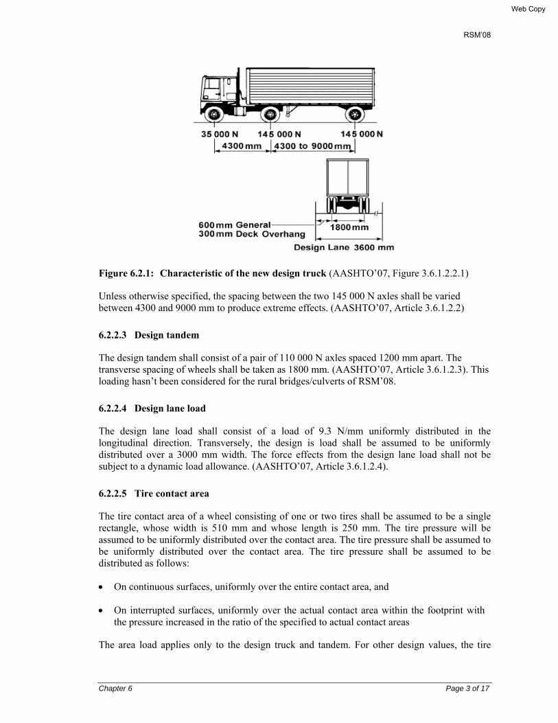
Figure 6.2.1: Characteristic of the new design truck (AASHTO’07, Figure 3.6.1.2.2.1)
Unless otherwise specified, the spacing between the two 145 000 N axles shall be varied between 4300 and 9000 mm to produce extreme effects. (AASHTO’07, Article 3.6.1.2.2)
6.2.2.3 Design tandem
The design tandem shall consist of a pair of 110 000 N axles spaced 1200 mm apart. The transverse spacing of wheels shall be taken as 1800 mm. (AASHTO’07, Article 3.6.1.2.3). This loading hasn’t been considered for the rural bridges/culverts of RSM’08.
6.2.2.4 Design lane load
The design lane load shall consist of a load of 9.3 N/mm uniformly distributed in the longitudinal direction. Transversely, the design is load shall be assumed to be uniformly distributed over a 3000 mm width. The force effects from the design lane load shall not be subject to a dynamic load allowance. (AASHTO’07, Article 3.6.1.2.4).
6.2.2.5 Tire contact area
The tire contact area of a wheel consisting of one or two tires shall be assumed to be a single rectangle, whose width is 510 mm and whose length is 250 mm. The tire pressure will be assumed to be uniformly distributed over the contact area. The tire pressure shall be assumed to be uniformly distributed over the contact area. The tire pressure shall be assumed to be distributed as follows:
• On continuous surfaces, uniformly over the entire contact area, and
• On interrupted surfaces, uniformly over the actual contact area within the footprint with the pressure increased in the ratio of the specified to actual contact areas
The area load applies only to the design truck and tandem. For other design values, the tire
Web Copy

RSM’08
Chapter 6 Page 4 of 17
contact area should be determined by the engineer.
As a guideline for other truck loads, the tire area in mm2 may be calculated from the following dimensions:
Tire width P/142
Tire length = 165γ (1 + IM/100)
Where,
γ = load factor
IM = dynamic load allowance percent
P = wheel load (N)
A dynamic load allowance shall be permitted as in Table 6.2.2. The static effect of the design truck or tandem, other than the centrifugal and braking forces, shall be increased by the percentage specified in the above Table 6.2.2 for dynamic load allowance IM.
The factor to be applied to the static load shall be taken as: (1 +IM/100). The dynamic load allowance shall not be applied to pedestrian loads o to the design lane load. (Ref.: AASHTO’07, Article 3.6.2)
Table 6.2.2 Dynamic Load Allowance, IM
Component IM
Deck Joints – All limit States 75%
All other components
• Fatigue and Fracture Limit State
• All Other limit States
15%
33%
6.2.2.6 Multiple presence of live load
The multiple presence factors, m is given in Table 6.2.3.
Table 6.2.3 Multiple presence factor, m
Number of loaded lanes Multiple presence factors m
1 1.20
2 1.00
3 0.85
>3 0.65
Web Copy

RSM’08
Chapter 6 Page 5 of 17
6.2.2.7 Pedestrian loads
AASHTO’07, Article 3.6.1.6 requires that a pedestrian load of 3.6x10⁻³ MPa shall be applied to all sidewalks wider than 600 mm and considered simultaneously with the vehicular design live load.
Bridges for only pedestrian and/or bicycle traffic shall be designed for a live load of 4.1x10⁻³ MPa.
Where sidewalks, pedestrian, and/or bicycle bridges are intended to be used by maintenance and/or other incidental vehicles, these loads shall be considered in the design. The dynamic load allowance need not be considered for these vehicles.
Where vehicles can mount the sidewalk, sidewalk pedestrian load shall not be considered concurrently.
6.2.3 Longitudinal forces due to braking force: BR
The braking force shall be taken as the greater of:
• 25 % of the axle weights of the design truck or design tandem or,
• 5% of the design truck plus lane load or 5% of the design tandem plus lane load
This braking force shall be placed in all design lanes and which are carrying traffic headed in the same direction. These forces shall be assumed to act horizontally at a distance of 1800 mm above the roadway surface in either longitudinal direction to cause extreme force effects. All design lanes shall be simultaneously loaded for bridges likely to become one-directional in future (Ref: AASHTO'07, Art. 3.6.4). 6.3 EARTH PRESSURE 6.3.1 Backfill The pressure on abutment-wing wall due to backfill is a function of the relative movement between the structure and the surrounding soil. Silt and lean clay shall not be used for backfill unless suitable design procedures are followed and construction control measures are incorporated in the construction documents to account for their presence. (AASHTO’07, Article 3.11.1). Consideration shall be given for the development of pore water pressure within the soil mass (For further details, refer to AASHTO’07, Article 3.11.3).
6.3.2 Active state lateral earth pressure Active earth pressure occurs when the wall moves away from the soil and the soil mass stretches horizontally sufficient to mobilize its shear strength fully, and a condition of plastic equilibrium is reached. According to Terzaghi, this movement may either be translational or rotational. The ratio of the horizontal component of active pressure to the vertical stress caused by the weight of the soil at this stage is the active pressure coefficient (ka). The active earth pressure coefficient as defined above applies to cohesionless soil only.
Web Copy

RSM’08
Chapter 6 Page 6 of 17
Values for the coefficient of active lateral earth pressure, ka, may be taken as:
ka = sin2 (θ + Φf’)/[Γ {sin2 θ sin(θ - Φf’)}]
in which,
Γ = [1 + √{sin(Φf’ + δ) sin(Φf’ – β)/{sin(θ - δ) sin(θ + β)]2
where,
δ = friction angle between fill and wall (0)
β = angle of fill to the horizontal (0)
θ = angle of back face of wall to the horizontal (0)
Φf’= effective angle of internal friction (0)
6.3.3 Passive state lateral earth pressure Passive earth pressure occurs when soil mass is compressed horizontally, mobilizing its shear resistance fully. The ratio of the horizontal component of passive pressure to the vertical stress caused by the weight of the soil is the passive pressure coefficient (kp). The passive coefficient as defined here, applies to cohesionless soil only. The passive earth pressure pp (MPa) may be determined from the equation pp = kp γsgz x 10-9 + 2c√ kp Where, γs = density of soil (kg/m3) z = depth below surface of soil (mm) c = soil cohesion (MPa) kp = coefficient of passive lateral earth pressure specified in AASHTO’07, Figures
3.11.5.4-1 & 3.11.5.4-2 (Ref.: Appendix 1 & 2).
6.3.4 At Rest earth pressure
A soil mass that is neither stretched nor compressed is said to be in at-rest state. The ratio of lateral stress to vertical stress at this state is called the at-rest coefficient (K0).
For normally consolidated soils, vertical wall, and level ground, the coefficient of at rest lateral earth pressure, k0 , may be taken as:
Web Copy

RSM’08
Chapter 6 Page 7 of 17
k0 = 1 - sinΦf’
where,
Φf’ = effective friction angle of soil
6.3.5 Wall movement vis-à-vis active and passive pressure
Walls that can tolerate little or no movement should be designed for at rest pressure. Walls which can move away from the soil mass should be designed for pressures between active and at rest conditions, depending on the magnitude of tolerable movements. Movement required reaching the minimum active pressure or the maximum passive pressure is a function of the wall height and the soil type. Some typical values of these mobilizing movements, relative to wall height, are given in Table 6.3.1, where,
∆ = movement of top of wall required to reach minimum active or maximum passive pressure by tilting or lateral transition (mm)
H = height of wall (mm)
Table 6.3.1 Approximate values of relative movements required to reach active or passive state earth pressure conditions (reproduced from AASHTO’07, table C3.11.1-1
Type of backfill Values of ∆/H Active Passive
Dense sand 0.001 0.01 Medium dense sand 0.002 0.02 Loose sand 0.004 0.04 Compacted silt 0.002 0.02 Compacted lean clay 0.010 0.05 Compacted fat clay 0.010 0.05
The evaluation of the stress induced by cohesive soils is highly uncertain due to their sensitivity to shrink-swell, wet-dry and degree of saturation. Tension cracks can form, which considerably alter the assumptions for the estimation of stress. Extreme caution is advised in the determination of lateral earth pressure assuming the most unfavorable conditions. If possible, cohesive or other fine grained soils should be avoided as backfill.
The standard structures of this Manual have been designed considering the granular soil as the backfill only.
The center of gravity of the longitudinal force has been assumed to be located 1.83 meter above the floor slab and to be transmitted to the substructure through the bridge bearings.
Web Copy
RSM’08
Chapter 6 Page 8 of 17
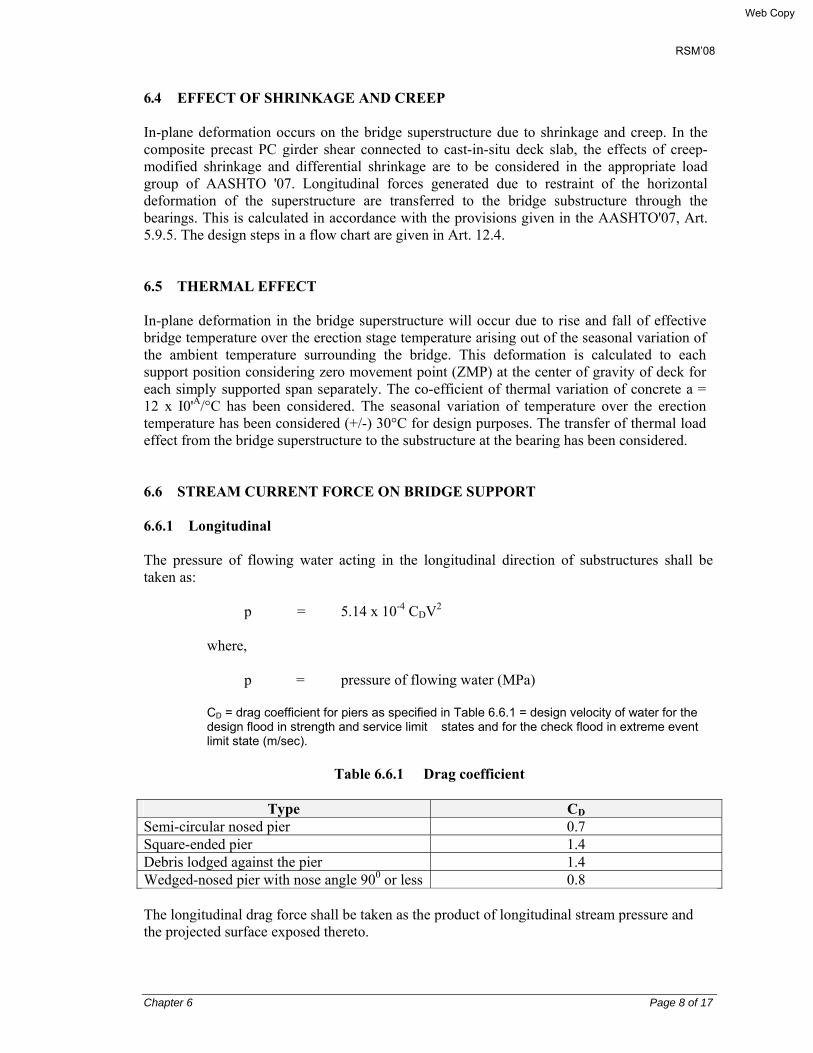
6.4 EFFECT OF SHRINKAGE AND CREEP In-plane deformation occurs on the bridge superstructure due to shrinkage and creep. In the composite precast PC girder shear connected to cast-in-situ deck slab, the effects of creep-modified shrinkage and differential shrinkage are to be considered in the appropriate load group of AASHTO '07. Longitudinal forces generated due to restraint of the horizontal deformation of the superstructure are transferred to the bridge substructure through the bearings. This is calculated in accordance with the provisions given in the AASHTO'07, Art. 5.9.5. The design steps in a flow chart are given in Art. 12.4. 6.5 THERMAL EFFECT In-plane deformation in the bridge superstructure will occur due to rise and fall of effective bridge temperature over the erection stage temperature arising out of the seasonal variation of the ambient temperature surrounding the bridge. This deformation is calculated to each support position considering zero movement point (ZMP) at the center of gravity of deck for each simply supported span separately. The co-efficient of thermal variation of concrete a = 12 x I0'A/°C has been considered. The seasonal variation of temperature over the erection temperature has been considered (+/-) 30°C for design purposes. The transfer of thermal load effect from the bridge superstructure to the substructure at the bearing has been considered. 6.6 STREAM CURRENT FORCE ON BRIDGE SUPPORT 6.6.1 Longitudinal The pressure of flowing water acting in the longitudinal direction of substructures shall be taken as:
p = 5.14 x 10⁻⁴ CDV2
where, p = pressure of flowing water (MPa) CD = drag coefficient for piers as specified in Table 6.6.1 = design velocity of water for the design flood in strength and service limit states and for the check flood in extreme event limit state (m/sec).
Table 6.6.1 Drag coefficient
Type CD
Semi-circular nosed pier 0.7 Square-ended pier 1.4 Debris lodged against the pier 1.4 Wedged-nosed pier with nose angle 900 or less 0.8 The longitudinal drag force shall be taken as the product of longitudinal stream pressure and the projected surface exposed thereto.
Web Copy

RSM’08
Chapter 6 Page 9 of 17
6.6.2 Lateral
The lateral, uniformly distributed pressure on a substructure due to water flowing at an angle, θ, to the longitudinal axis of the pier shall be taken as:
p = 5.14 x 10⁻⁴ CLV2
where, p = lateral pressure (MPa) CL = lateral drag coefficient in Table 6.6.2
Table 6.6.2 Lateral drag coefficient
Type CD
Angle, θ, between direction of flow and longitudinal axis of pier
00 0.0
50 0.5
100 0.7
200 0.9
≥300 1.0 The lateral drag force shall be taken as the product of lateral stream pressure and the surface exposed thereto.
6.7 WIND LOAD
The wind speed for a structure shall be read from the Basic Wind Speed Map given in the Bangladesh National Building Code 1993 (BNBC '93), Fig. 6.2.1 (ref: Plate 6-1). A basic wind speed of 240 km/hr has been considered for the design of the standard structures of this Manual. Wind pressure on the bridge shall be calculated based on BNBC’93 & AASHTO’07.
Web Copy

RSM’08
Chapter 6 Page 10 of 17
Plate 6-1
Web Copy
RSM’08
Chapter 6 Page 11 of 17
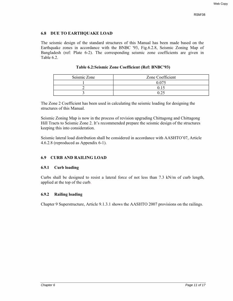
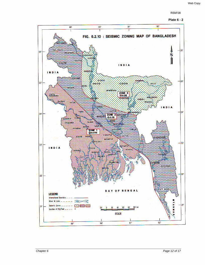
6.8 DUE TO EARTHQUAKE LOAD
The seismic design of the standard structures of this Manual has been made based on the Earthquake zones in accordance with the BNBC '93, Fig.6.2.8, Seismic Zoning Map of Bangladesh (ref: Plate 6-2). The corresponding seismic zone coefficients are given in Table 6.2.
Table 6.2:Seismic Zone Coefficient (Ref: BNBC'93)
Seismic Zone Zone Coefficient 1 0.075 2 0.15 3 0.25
The Zone 2 Coefficient has been used in calculating the seismic loading for designing the structures of this Manual. Seismic Zoning Map is now in the process of revision upgrading Chittagong and Chittagong Hill Tracts to Seismic Zone 2. It’s recommended prepare the seismic design of the structures keeping this into consideration. Seismic lateral load distribution shall be considered in accordance with AASHTO’07, Article 4.6.2.8 (reproduced as Appendix 6-1). 6.9 CURB AND RAILING LOAD 6.9.1 Curb loading Curbs shall be designed to resist a lateral force of not less than 7.3 kN/m of curb length, applied at the top of the curb.
6.9.2 Railing loading Chapter 9 Superstructure, Article 9.1.3.1 shows the AASHTO 2007 provisions on the railings.
Web Copy
RSM’08
Chapter 6 Page 12 of 17
Plate 6 - 2
Web Copy

RSM’08
Chapter 6 Page 13 of 17
6.10 COMBINATION OF LOADS 6.10.1 Load and load Designation AASHTO’07, Article 3.3.2 requires that the following permanent and transient loads and forces will be considered:
• Permanent loads DD = Down drag DC = Dead load of structural components and nonstructural attachments DW = Dead load of wearing surfaces and utilities EH = Horizontal earth pressure load EL = Accumulated locked-in force effects resulting from the construction process, including the secondary forces from post-tensioning ES = Earth surcharge load EV = Vertical pressure from dead load of earth fill
• Transient Loads BR = Vehicular braking force CE = Vehicular centrifugal force CR = Creep CT = Vehicular collision force CV = Vessel collision force EQ = Earthquake Fr = Friction IC = Ice load IM = Vehicular dynamic load allowance LL = Vehicular live load LS = Live load surcharge PL = Pedestrian live load SE = Settlement SH = Shrinkage TG = Temperature gradient TU = Uniform temperature WA = Water load and stream pressure WL = Wind load on live load WS = Wind load on structure
Web Copy

RSM’08
Chapter 6 Page 14 of 17
6.10.2 Load factors and load combinations
The total factored force effects shall be taken, based on AASHTO’07, Article 3.4 & 1.3.2, as:
Q = ∑ηi γi Qi (AASHTO’07, Eq. 3.4.1-1)
∑ηi γi Qi ≤ фRn = Rr (AASHTO’07, Eq. 1.3.2.1-1)
in which,
For loads where a maximum value of γi is appropriate:
ηi = ηD ηR ηl ≥ 0.95 (AASHTO’07, Eq. 1.3.2.1-2)
For loads where a Minimum value of γi is appropriate:
ηi = 1/ (ηD ηR ηl) ≤1.0 (AASHTO’07, Eq. 1.3.2.1-3)
where,
γi = Load factors specified in AASHTO’07, Tables 3.4.1-1 & 3.4.1-2.
ηi = Load modifier, a factor relating to ductility, redundancy, and operational importance
ηD = A factor relating to ductility
ηR = A factor relating to redundancy
ηl = A factor relating to operational importance
ф = Resistance factor: a statistically based multiplier applied to nominal resistance, as specified in AASHTO’07, Sections 5,6,7,8,10,11, and 12.
Qi = Force effects from loads specified herein
Rn = Nominal resistance
Rr = Factored resistance: фRn
Components and connections of a bridge/culvert shall satisfy the above equations for the applicable combinations of factored extreme force effects as specified at each of the following limit states:
• STRENGTH I − Basic load combination relating to the normal vehicular use of the bridge without wind. A reduced value of TU, CR, and SH, used when calculating force effects other than displacements at the strength limit state. The calculation of displacements for these loads utilizes a factor grater than 1.0 to avoid undersized joins and bearings.
• STRENGTH II − Load combination relating to the use of bridge/culvert by Owner-specified special design vehicles, evaluation permit vehicles, or both without wind.
• STRENGTH III − Load combination relating to the bridge/culvert exposed to wind velocity exceeding 90 km/hr. Vehicles become unstable at higher wind velocities. Therefore, high winds prevent the presence of significant live load on the bridge.
• STRENGTH IV − Load combination relating to very high dead load to live load force effect.
Web Copy

RSM’08
Chapter 6 Page 15 of 17
• STRENGTH V − Load combination relating to normal vehicular use of the bridge with wind load of 90 km/hr velocity.
• EXTREME EVENT I − Load combination including earthquake. The recurrence interval of extreme events is thought to exceed design life.
• EXTREME EVENT II − Load combination relating to ice load, collision by vessels and vehicles, and certain hydraulic events with a reduced live load other than that which is part of the vehicular collision load, CT.
• SERVICE I − Load combination relating to the normal operational use of the bridge with a 90 km/hr win and all loads taken at their nominal values. Also related to deflection control in buried metal structures, tunnel liner plate, and thermoplastic pipe, to control crack width in reinforced concrete (RC) structures, and for transverse analysis relating to tension in concrete segmental girders. This load combination should also be used for the investigation of slope stability.
• SERVICE II − Load combination intended to control yielding of steel structures and slip f slip-critical connections due to vehicular live load.
• SERVICE III − Load combination for longitudinal analysis relating to tension in prestressed concrete superstructures with the objective of crack control and to principal tension in the webs of segmental concrete girders.
• SERVICE IV − Load combination relating only to tension in prestressed concrete columns with the objective of crack control. The 0.7 factor on wind represents a 135 km/hr wind.
It is not recommended that thermal gradient be combined with high wind forces. Superstructure expansion forces are included.
• FATIGUE − Fatigue and fracture load combination relating o repetitive gravitational vehicular live load and dynamic responses under a single design truck having the axle spacing specified in AASHTO’07, Article 3.6.1.4.1.
The load factors for various loads comprising a design load combination shall be taken as specified in AASHTO’07, Tables 3.4.1-1 & 3.4.2-1, is given as Plate 6.3 below.
The larger of the two values provided for load factors of TU, CR, and SH shall be used for deformations and the smaller values for all other effects.
The load factor for temperature gradient, γTG, should be considered on a project-specific basis. Normally γTG may be taken as 0.0 at the strength and extreme event limit states; 1.0 at the service limit state when live load is to be considered, and 0.5 when live load is not considered.
Similarly, the load factor for settlement, γSE, should be considered on a project-specific basis.
Web Copy

RSM’08
Chapter 6 Page 16 of 17
Plate 6 - 3
Web Copy
RSM’08
Chapter 6 Page 17 of 17
6.10.3 Load factors for construction loads (Ref.: AASHTO’07, Article 3.4.2) 6.10.3.1 Evaluation at the strength limit state All appropriate strength load combinations in Table 3.4.1-1, modified as specified herein, shall be investigated. When investigating Strength Load Combination I, III, and V during construction, load factors for the weight of the structure and appurtenances, DC and DW, shall not be taken less than 1.25. Unless otherwise specified by the Owner, the load factor for construction loads and for any associated dynamic effects shll not be less than 1.5 in Strength Load Combination I. The load factor for wind in Strength Load Combination III shall not be less than 1.25.
6.10.3.2 Evaluation of deflection at the service limit state In the absence of special provisions in the contrary, where evaluation of construction deflections are required by the contract documents, Load Combination Service I shall apply. Construction dead load shall be considered as part of the permanent load and construction transient loads considered part of the live load. The associated permitted deflections shall be included in the contract documents.
6.10.4 Load factors for jacking and post-tensioning forces (Ref.: AASHTO’07, Article 3.4.3)
6.10.4.1 Jacking forces Unless otherwise specified by the Owner, the design forces for jacking in service shall not be less than 1.3 times the permanent load reaction at the bearing, adjacent to the point of jacking. Where the bridge will jot be closed to traffic during the jacking operation, the jacking load shall also contain a live load reaction consistent with the maintenance of traffic plan, multiplied by the load factor for live load.
6.10.4.2 Force for post-tensioning anchorage zones The design force for post-tensioning anchorage zones shall be taken as 1.2 times the maximum jacking force.
Web Copy

RSM’08
Chapter 7 Page 1 of 8
CHAPTER 7
MATERIAL STRENGTH, PROPERTIES AND QUALITY CONTROL TESTS
7.1 GENERAL
For the material strength, properties and tests the relevant BDS, AASHTO, ASTM, BS, or equivalent other Standards are mainly to be followed: 7.2 CEMENT 7.2.1 Cement types
Bangladesh standards Institution have adopted the European Standard EN 197 – 1: 2000 as the BDS Standard for cement, and have circulated it as BDS EN 197 – 1, April 2003. Its Part 1: Composition, specifications and conformity criteria for common cements, Table 1 gives the 27 products in the family of common cements. These are grouped into 5 common types as follows:
• CEMI - Portland cement
• CEMII - Portland-slag cement (CEMII/A-S & CEMII/B-S), Portland-silica fume cement (CEMII/A-D), Portland Pozzolana cement (CEMII/A-P, CEMII/B-P, CEMII/A-Q, & CEMII/B-Q), Portland-fly ash cement (CEMII/B-V, CEMII/A-W, CEMII/B-W), Portland-burnt shale cement (CEMII/A-T, CEMII/B-T), Portland-lime stone cement (CEMII/A-L, CEMII/B-L, CEMII/A-LL, & CEMII/B-LL), Portland-composite cement (CEMII/A-M, CEMII/B-M)
• CEMIII - Blast furnace cement (CEMIII/A, CEMIII/B, CEMIII/C)
• CEMIV - Pozzolanic cement (CEMIV/A & CEMIV/B)
• CEMV - Composite cement (CEMV/A & CEMV/B)
7.2.2 Mechanical Requirements The standard strength of cement is the compressive strength determined in accordance with EN 196 – 1 at 28 days and shall conform to the requirements given in its Table 2 (reproduced below in Table 7.3.2). The Table shows 3 classes of standard strength: class 32.5, 42.5 and 52.5. The early strength of cement is the compressive strength determined in accordance with EN 196 – 1 at either 2 days or 7 days and shall conform to the requirement in Table 7.3.2. Two classes of easy strength are included for each class of standard strength, a lass with ordinary early strength, indicated by N, and a class with high early strength, indicated by R (see Table 7.1).
Web Copy
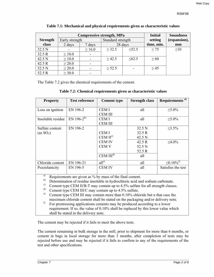
RSM’08
Chapter 7 Page 2 of 8
Table 7.1: Mechanical and physical requirements given as characteristic values
Strength
class
Compressive strength, MPa Initial setting
time, min.
Soundness (expansion),
mm Early strength Standard strength
2 days 7 days 28 days 32.5 N - ≥ 16.0 ≥ 32.5 ≤52.5 ≥ 75 ≤10 32.5 R ≥ 10.0 - 42.5 N ≥ 10.0 - ≥ 42.5 ≤62.5 ≥ 60 42.5 R ≥ 20.0 - 52.5 N ≥ 20.0 - ≥ 52.5 - ≥ 45 52.5 R ≥ 30.0 -
The Table 7.2 gives the chemical requirements of the cement.
Table 7.2: Chemical requirements given as characteristic values
Property Test reference
Cement type Strength class Requirements a)
Loss on ignition EN 196-2 CEM I CEM III
all ≤5.0%
Insoluble residue EN 196-2b) CEM I CEM III
all ≤5.0%
Sulfate content (as SO3)
EN 196-2 CEM I CEM IIc) CEM IV CEM V
32.5 N 32.5 R 42.5 N
≤3.5%
42.5 R 52.5 N 52.5 R
≤4.0%
CEM IIId) all
Chloride content EN 196-21 alle) all ≤0.10%f) Pozzolanicity EN 196-5 CEM IV all Satisfies the test
a) Requirements are given as % by mass of the final cement. b) Determination of residue insoluble in hydrochloric acid and sodium carbonate. c) Cement type CEM II/B-T may contain up to 4.5% sulfate for all strength classes. d) Cement type CEM III/C may contain up to 4.5% sulfate. e) Cement type CEM III may contain more than 0.10% chloride but n that case the
maximum chloride content shall be stated on the packaging and/or delivery note. f) For prestressing applications cements may be produced according to a lower
requirement. If so, the value of 0.10% shall be replaced by this lower value which shall be stated in the delivery note.
The cement may be rejected if it fails to meet the above tests. The cement remaining in bulk storage in the mill, prior to shipment for more than 6 months, or cement in bags in local storage for more than 3 months, after completion of tests may be rejected before use and may be rejected if it fails to confirm to any of the requirements of the test and other specifications.
Web Copy

RSM’08
Chapter 7 Page 3 of 8
7.3 FINE AGGREGATE The fine aggregate for Portland cement concrete should conform to AASHTO Designation: M6-87 or BS 882:1983 or equivalent standards. This shall consist of natural or manufactured sand or combination thereof, having hard, strong durable particles to the requirement of the specification.
The following tests shall be performed:
• Grading by sieve analysis AASHTO T 27 or BS 812:Sec.103.1.1985 • Fineness modulus AASHTO M 6-87 • Deleterious substances e.g. clay AASHTO T 112 Lumps and friable particles • Organic impurities AASHTO T 12
Fine aggregate for use in concrete, that will be subjected to wetting, extended to humid atmosphere, or contacted with moist ground, shall not contain any materials that are deleteriously reactive with the alkalis in the cement in an amount sufficient to cause excessive expansion of mortar or concrete. If such materials are present in injurious amounts, the fine aggregate may be used with cement containing less than 0.6 percent alkalis or with addition of material that has been shown to prevent harmful expansion due to the alkali-silicate reaction. 7.4 COARSE AGGREGATE The coarse aggregate for Portland cement concrete should conform to AASHTO Designation: M80-87 or BS 882:1983 or equivalent standards. This shall consist of gravel, crushed gravel, crushed stone or broken picked jhama bricks or a combination thereof to the requirements of the specification. The nominal size used for this RSM’08 structures is 20 mm downgraded.
The following tests shall be performed:
• Grading (Sieve analysis) AASHTO T27 & M43 or BS 812:
Sec.103.1.1985 • Deleterious substances e.g. clay lumps AASHTO T 112 and friable particles in aggregate • Resistance to abrasions by use of the AASHTO T 96 Los Angeles machine • Soundness of aggregate AASHTO T 104 • Water Absorption Tests for Bricks
The coarse aggregate for use in concrete that will be subjected to wetting, extended exposure to humid atmosphere or contacted with moist ground shall not contain any material that are deleteriously reactive with the alkalis in the cement in an amount sufficient to cause excessive expansion of mortar or concrete. If such materials are present in injurious amounts, the coarse aggregate may be used with cement containing less than 0.6 percent alkalis or with the addition
Web Copy
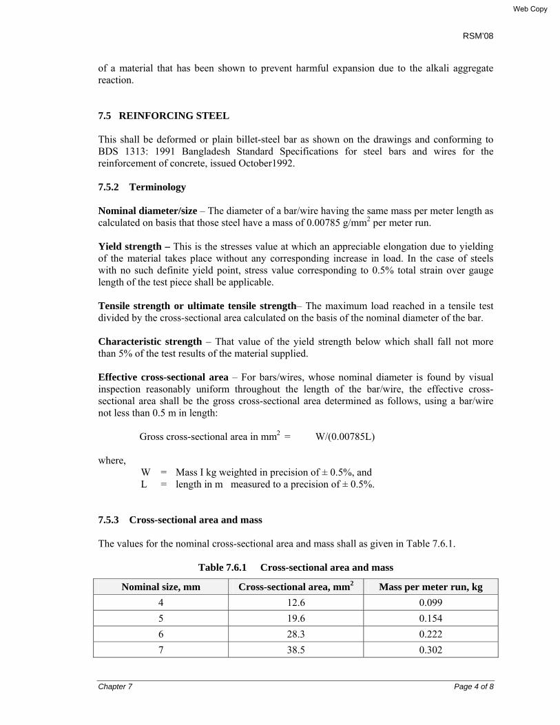
RSM’08
Chapter 7 Page 4 of 8
of a material that has been shown to prevent harmful expansion due to the alkali aggregate reaction. 7.5 REINFORCING STEEL This shall be deformed or plain billet-steel bar as shown on the drawings and conforming to BDS 1313: 1991 Bangladesh Standard Specifications for steel bars and wires for the reinforcement of concrete, issued October1992.
7.5.2 Terminology Nominal diameter/size – The diameter of a bar/wire having the same mass per meter length as calculated on basis that those steel have a mass of 0.00785 g/mm2 per meter run. Yield strength – This is the stresses value at which an appreciable elongation due to yielding of the material takes place without any corresponding increase in load. In the case of steels with no such definite yield point, stress value corresponding to 0.5% total strain over gauge length of the test piece shall be applicable. Tensile strength or ultimate tensile strength– The maximum load reached in a tensile test divided by the cross-sectional area calculated on the basis of the nominal diameter of the bar. Characteristic strength – That value of the yield strength below which shall fall not more than 5% of the test results of the material supplied. Effective cross-sectional area – For bars/wires, whose nominal diameter is found by visual inspection reasonably uniform throughout the length of the bar/wire, the effective cross-sectional area shall be the gross cross-sectional area determined as follows, using a bar/wire not less than 0.5 m in length:
Gross cross-sectional area in mm2 = W/(0.00785L)
where,
W = Mass I kg weighted in precision of ± 0.5%, and L = length in m measured to a precision of ± 0.5%.
7.5.3 Cross-sectional area and mass The values for the nominal cross-sectional area and mass shall as given in Table 7.6.1.
Table 7.6.1 Cross-sectional area and mass
Nominal size, mm Cross-sectional area, mm2 Mass per meter run, kg 4 12.6 0.099 5 19.6 0.154 6 28.3 0.222 7 38.5 0.302
Web Copy
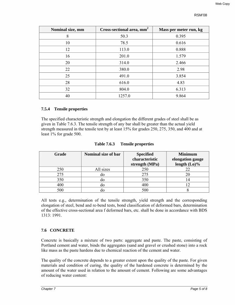
RSM’08
Chapter 7 Page 5 of 8
Nominal size, mm Cross-sectional area, mm2 Mass per meter run, kg 8 50.3 0.395 10 78.5 0.616 12 113.0 0.888 16 201.0 1.579 20 314.0 2.466 22 380.0 2.98 25 491.0 3.854 28 616.0 4.83 32 804.0 6.313 40 1257.0 9.864
7.5.4 Tensile properties The specified characteristic strength and elongation the different grades of steel shall be as given in Table 7.6.3. The tensile strength of any bar shall be greater than the actual yield strength measured in the tensile test by at least 15% for grades 250, 275, 350, and 400 and at least 1% for grade 500.
Table 7.6.3 Tensile properties
Grade Nominal size of bar Specified
characteristic strength (MPa)
Minimum elongation gauge
length (Lo)% 250 All sizes 250 22 275 do 275 20 350 do 350 14 400 do 400 12 500 do 500 8
All tests e.g., determination of the tensile strength, yield strength and the corresponding elongation of steel, bend and re-bend tests, bond classification of deformed bars, determination of the effective cross-sectional area f deformed bars, etc. shall be done in accordance with BDS 1313: 1991. 7.6 CONCRETE Concrete is basically a mixture of two parts: aggregate and paste. The paste, consisting of Portland cement and water, binds the aggregates (sand and gravel or crushed stone) into a rock like mass as the paste hardens due to chemical reaction of the cement and water.
The quality of the concrete depends to a greater extent upon the quality of the paste. For given materials and condition of curing, the quality of the hardened concrete is determined by the amount of the water used in relation to the amount of cement. Following are some advantages of reducing water content:
Web Copy

RSM’08
Chapter 7 Page 6 of 8
• Increased compressive and flexural strength • Increased water tightness • Lower absorption • Increased resistance to weathering • Better bond between successive layer • Better bond between concrete and reinforcement • Less volume change from wetting and drying
The less water is used; the better will be the quality of the concrete, provided it can be compacted properly. Vibration or consolidation permits improvement in the quality of concrete and in economy.
Freshly mixed concrete should be plastic or semi-fluid, capable of being molded by hand. A plastic mix keeps all grains of sand and pieces of gravel or stone encased and held in place without segregation. A plastic and cohesive paste is attained with a low water-cement ratio and the correct proportions for all ingredients.
The following classes of concrete have been used for the standard design of RSM’08:
• Class 10 28 days cylinder crushing strength fc’ = 10 MPa • Class 15 28 days cylinder crushing strength fc’ = 15 MPa • Class 20 28 days cylinder crushing strength fc’ = 20 MPa • Class 25 28 days cylinder crushing strength fc’ = 25 MPa • Class 30 28 days cylinder crushing strength fc’ = 30 MP • Class 35 28 days cylinder crushing strength fc’ = 35 MPa
Class 10 shall be used mainly for plain concrete below foundation; Class 15 also may be used for plain concrete in other cases; Class 20 & 25 shall be used for RC components of superstructure, substructures, and piles, as shown on drawings. Class 30 & 35 concrete shall be used for prestressed concrete.
For Class 20 & 25 concrete used in the superstructure RC deck girders, minimum cement content may be used 330 & 350 kg/m3, and maximum water cement ratio may be used 0.5.
Mixing Water for Concrete
Almost any natural water that is drinkable, and has no pronounced taste or odor can be used as mixing water for making concrete.
Water of questionable suitability can be used for making concrete if mortar cubes made with it have 7 days and 28 days strengths equal to at least 90% of that specimens made with drinkable water. Mortar cubes should be made and tested according to ASTM Designation: C109- Standard Method of test for compressive strength of Hydraulic cement mortars. In addition, ASTM Designation: C191-Vicat Needle tests should be made to ensure that impurities in the mixing water do not adversely shorten or extend the setting time of the cement.
Water containing less than 2000 parts per million (ppm) of total dissolved solids can generally be used satisfactorily for making concrete.
The Chemical limit of mixing water is given in Table 7.6.4
Web Copy

RSM’08
Chapter 7 Page 7 of 8
Table 7.6.4 Chemical Limits for Mixing Water
Chemicals Maximum Concentration (ppm) Test Method
Chloride as ‘Cl’ • Concrete in Bridge Decks • Other reinforced concrete in moist
environments
Sulphate as ‘SO4’ Alkalis as (Na2O + 0.658K2O) Total solids
500 1000
3000
600
50000
ASTM D512
ASTM D516
AASHTO T 26
Adapted from PCA Design and Control of Concrete Mixtures 12th ed. 1979. 7.7 ADMIXTURE FOR CONCRETE
Admixtures are those ingredients in concrete other than Portland cement, water and aggregates that are added to the mixture immediately before or during mixing.
Prior approval will be needed for the use of admixtures in concrete.
Admixtures, if used in concrete for water reducing, retarding, accelerating, water reducing but retarding, and water reducing but accelerating, shall conform to ASTM C494: Specification for chemical admixtures of concrete or ASTM C1017: Specification for chemical admixtures for use in producing Flowing Concrete.
The classification of admixtures used in the work is given in Table 7.6.5.
Table 7.6.5 Admixtures by classification
Desired Effect Type of Admixture Material Reduce water required for given consistency Retard setting time Accelerate setting and early-strength development Reduce water and retard setting Reduce water and accelerate setting
Water reducer (ASTM C494. Type A) Retarder (ASTM C494 Type B) Accelerator (ASTM C494 Type C) Water reducer and retarder (ASTM C494 Type D) Water reducer and
Lignosulfonates, Hydroxylated carboxylic acids. (Also tend to retard set so accelerator is added) Lignin, Borax, Sugars Tartaric acid and salts Calcium chloride (ASTM D98) Triethanolamine (See water reducer, Type A, above) (See water reducer, Type A, above More accelerator is added)
Web Copy

RSM’08
Chapter 7 Page 8 of 8
Desired Effect Type of Admixture Material Improve workability and plasticity.
accelerator (ASTM C494 Type E) Pozzolan (ASTM C618)
Natural pozzolans (Class N) Fly ash (Class F and C) Other materials (Class S)
Adapted from ‘PCA Design and Control of Concrete Mixtures’, 12th ed., 1979.
Web Copy

RSM’08
Chapter 8 Page 1 of 15
CHAPTER 8 CONCRETE STRUCTURES
8.1 GENERAL The provisions in this section have been prepared mainly based on AASHTO’07, Section 5 (SI) Concrete structures. These shall apply to the design of bridge, culvert, retaining walls, and slope protection works components constructed of normal density or low-density concrete and reinforced with steel bars, welded wire reinforcement, and/or prestressing strands, bars or wires. The provisions of this section combine and unify the requirements for reinforced, prestressed, and partially prestressed concrete. Provision for seismic design, analysis y the strut-and-tie model, and bridges made from precast concrete elements have been included. 8.2 DEFINITIONS
Anchorage
In post-tensioning, a mechanical device used to anchor the tendon to the concrete; in pre-tensioning, a device used to anchor the tendon until the concrete has reached a predetermined strength, and the prestressing force has been transferred to the concrete; for a reinforcing bars, a length of reinforcement, or a mechanical anchor or hook, or combination thereof at the end of a bar needed to transfer the force carried y the bar into the concrete.
Anchorage Blister
A build-up area on the web, flange, or flange-web junction for the incorporation of tendon anchorage fittings.
Anchorage Zone
The portion of the structure in which the prestressing force is transferred from the anchorage device onto the local zone of the concrete, and then distributed more widely in the general zone of the structure.
At Jacking
At the time of tensioning, the prestressing tendons.
At Loading
The maturity of the concrete when loads are applied. Such loads include prestressing forces and permanent loads but generally not live loads.
At Transfer
Immediately after the transfer of prestressing force to the concrete.
Bonded Tendon
A tendon that is bonded to the concrete either directly or by means of grouting.
Web Copy

RSM’08
Chapter 8 Page 2 of 15
Bursting Force
Tensile forces in the concrete in the vicinity of the transfer or anchorage of prestressing forces.
Cast-in-Place Concrete
Concrete placed in its final position in the structure while still in a plastic state.
Closely Spaced Anchorages
Anchorage devices are defined as closely spaced if their center-t-center spacing does not exceed 1.5 times the width of the anchorage devices in the direction considered.
Closure
A placement of cast-in-place concrete used to connect two or more previously cast portions of a structure.
Composite Construction
Concrete components or concrete and steel components interconnected to respond to force effects as a unit.
Compression-Controlled Section
A cross-section in which the net tensile strain in the extreme tension steel at nominal resistance is less than or equal to the compression-controlled strain limit.
Compression-Controlled Strain Limit
The net tensile strain in the extreme tension steel at balanced strain conditions, See AASHTO’07, Article 5.7.2.1.
Concrete Cover
The specified minimum distance between the surface of the reinforcing bars strands, post-tensioning ducts, anchorages, or other embedded items, and the surface of the concrete.
Confinement
A condition where the disintegration of the concrete under compression is prevented by the development of lateral and/or circumferential forces such as may be provided by appropriate reinforcing, steel or composite tubes, or similar devices.
Confinement Anchorage
Anchorage for a post-tensioning tendon that functions on the basis of containment of the concrete in the local anchorage zone by special reinforcement.
Creep
Time-dependent deformation of concrete under permanent load.
Curvature Friction
Friction resulting from the tendon moving against the duct when tensioned due to the curvature of the duct.
Web Copy

RSM’08
Chapter 8 Page 3 of 15
Deck Slab
A solid concrete slab resisting and distributing wheel loads to the supporting components.
Decompression
The stage at which the compressive stresses, induced prestress, are overcome by the tensile stresses.
Deep Component
Components in which the distance from the point of 0.0 shear to the face of the support is less than 2d or components in which a load causing more than one-third of the shear at a support is closer than 2d from the face of the support.
Deviation Saddle
A concrete block build-out in web, flange, or web-flange junction used to control the geometry of or to provide a means for changing direction of, external tendons.
Development Length
The distance required to develop the specified strength of a reinforcing bar or prestressing strand.
Direct Loading/Supporting
Application of a load or use of a support external to the member, as in the case of point or uniform loads applied directly to the deck surface, simply-supported girder-ends, bent (pier) cap supported on pinned columns.
Edge Distance
The minimum distance between the centerline of reinforcement or other embedded elements and the edge of the concrete.
Effective Depth
The depth of a component effective in resisting flexural shear forces.
Effective Prestress
The stress or force remaining in the prestressing steel after all losses has occurred.
Embedment Depth
The length of reinforcement or another provided beyond a critical section over which transfer of force between concrete and reinforcement may occur.
External Tendon
A post-tensioning tendon placed outside of the body of concrete, usually inside a box girder.
Extreme Tension Steel
The reinforcement (prestressed or nonprestressed) that is farthest from the extreme compression fiber.
Web Copy
RSM’08
Chapter 8 Page 4 of 15
Fully Prestressed Component
Prestressed concrete component in which stresses satisfy the tensile stress limits at a Service Limit State specified herein. Such components are assumed to remain uncracked at the Service Limit State.
General Zone
Region adjacent to a post-tensioned anchorage within which the prestressing force spreads out to an essentially linear stress distribution over the cross-section of the component.
Intermediate Anchorage
Anchorage not located at the end surface of a member or segment for tendons that do not extend over the entire length of the member or segment; usually in the form of embedded anchors, blisters, ribs, or recess pockets.
Indirect Loading/Supporting
Application of load or use of a support internally such as girders framing into an integral part bent (pier) cap, draped or spliced-girders where load transfer is between the top and bottom face of the member, or utility loads hung fro the web of a girder.
Internal Tendon
A post-tensioning tendon placed within the body of concrete.
Isotropic Reinforcement
An arrangement of reinforcement in which the bars are orthogonal, and the reinforcement ratios in the two directions are equal.
Jacking Force
The force exerted by the device that introduces tension into the tendons.
Low-Density Concrete
Concrete containing low-density aggregate and having an air-dry density not exceeding 1925 kg/m3, as determined by ASTM C567. Low-density concrete without natural sand is termed “all-low-density concrete” and low-density concrete in which all of the fine aggregate consists of normal density sand is termed “sand-low-density concrete.”
Local Zone
The volume of concrete that surrounds and is immediately ahead of the anchorage device and that is subjected to high compressive stresses.
Low Relaxation Steel
Prestressing strand in which the steel relaxation losses have been substantially reduced by stretching at an elevated temperature.
Net Tensile Strain
The tensile strain at nominal resistance exclusive of strains de to effective prestress, creep, shrinkage, and temperature.
Web Copy

RSM’08
Chapter 8 Page 5 of 15
Normal-Density Concrete
Concrete having a density between 2150 and 2500 kg/m3.
Partially Debonded Strand
A pretensioned prestressing strand that is bond for a portion of its length and intentionally debonded elsewhere through the use of mechanical or chemical means. Also called shielded or blanketed strand.
Partially Prestressed Component
Concrete with a combination of prestressing strands and reinforcing bars.
Partially Prestressed Concrete
Concrete with a combination of prestressing strands and reinforcing bars.
Post-Tensioning
A method of prestressing in which the tendons are tensioned after the concrete has reached a predetermined strength.
Post-Tensioning Duct
A form device used to provide a path for post-tensioning tendons or bars in hardened concrete. The following types are in general use:
a) Rigid Duct
Seamless tubing stiff enough to limit the deflection of a 6000 mm length supported at its ends to not more than 25 mm
b) Semi-rigid Duct
A corrugated duct of metal or plastic sufficiently stiff to be regarded as not coilable into conventional shipping coils without damage.
c) Flexible Duct
A loosely interlocked duct that can be coiled into a 1200 mm diameter without damage.
Precast Members
Concrete elements cast in a location other than their final position.
Precompressed Tensile Zone
Any region of a prestressed component in which prestressing causes compressive stresses and service load effects cause tensile stresses.
Pressed Concrete
Concrete components in which stresses and deformations are introduced by application of prestressing forces.
Pretensioning
A method of prestressing in which the strands are tensioned before the concrete is placed.
Web Copy

RSM’08
Chapter 8 Page 6 of 15
Reinforced Concrete
Structural concrete containing no less than the minimum amounts of prestressing tendons or nonprestressed reinforcement specified herein.
Reinforcement
Reinforcing bars and/or prestressing steel.
Relaxation
The time-dependent reduction of stress in prestressing tendons.
Segmental construction
The fabrication and erection of a structural element (superstructure and/or substructure) using individual elements, which may be either precast or cast-in-place. The completed structural element acts as a monolithic unit under some or all design loads. Post-tensioning is typically used to connect the individual elements. For superstructures, the individual elements are typically short (with respect to the span length), box-shaped segments with monolithic flanges that comprise the full width of the structure.
Seismic Hoop
A cylindrical noncontinuously wound tie with closure made using a butt weld or a mechanical coupler.
Shielded Strand
Same as Partially Debonded Strand.
Slab
A component having a width of at least four times its effective depth.
Special Anchorage Device
Anchorage device whose adequacy should be proven in a standardized acceptance test. Most multiplane anchorages and all bond anchorages are special anchorage devices.
Specified Strength of Concrete
The nominal compressive strength of concrete specified for the work and assumed for design and analysis of new structures.
Spiral
Continuously wound bar or wire in the form of a cylindrical helix.
Spliced Precast Girder
A type of superstructure in which precast concrete beam-type elements are joined longitudinally, typically using post-tensioning, to form the completed girder. The bridge cross-section is typically a conventional structure consisting of multiple precast girders. This type of construction is not considered to be segmental construction for the purposes of these Specifications.
Web Copy

RSM’08
Chapter 8 Page 7 of 15
Splitting Tensile Strength
The tensile strength of concrete that is determined by a splitting test made in accordance with AASHTO T 198 (ASTM C 496)
Stress Range
The algebraic difference between the maximum and minimum stresses due to transient loads.
Structural Concrete
All concrete used for structural purposes.
Structural Mass Concrete
Any large volume of concrete where special materials or procedures are required to cope with the general of heat of hydration and attendant volume change to minimize cracking.
Strut-and-Tie Model
A model used principally in regions of concentrated forces and geometric discontinuities to determine concrete proportions and reinforcement quantities and patters based on assumed compression struts in the concrete, tensile ties in the reinforcement, and the geometry of nodes at the points of intersection.
Temperature Gradient
Variation of temperature of the concrete over the cross-section.
Tendon
A high strength steel element used to prestress the concrete.
Tension-Controlled Section
A cross-section in which the net tensile strain in the extreme tension steel at nominal resistance is greater than or equal to 0.005.
Transfer
The operation of imparting the force in a pretensioning anchoring device to the concrete.
Transfer Length
The length over which the pretensioning force is transferred to the concrete by bond and friction in a pretensioned member.
Transverse Reinforcement
Reinforcement used to resist shear, torsion, and lateral forces or to confine concrete in a structural member. The terms “stirrups” and “web reinforcement” are usually applied to transverse reinforcement in flexural members and the terms “ties”, “hoops” and “spirals” are applied to transverse reinforcement in a compression members.
Wobble Friction
The friction caused by the deviation of a tendon duct or sheath from its specified profile
Web Copy
RSM’08
Chapter 8 Page 8 of 15
Yield Strength
The specified yield strength of reinforcement. 8.3 LIMIT STATES 8.3.1 General
AASHTO’07, Article 5.5 requires that structural components shall be proportioned to satisfy the requirements at all appropriate service, fatigue, strength, and extreme event limit states. Pretsressed and partially pretressed concrete structural components shall be investigated for stresses and deformations for each stage that may be critical during construction, stressing, handling, transportation, and erection as well as during the service life of the structure of which they are part. Stress concentrations due to prestressing or other losses and to restraints or imposed deformations shall be considered.
8.3.2 Service Limit State Actions to be considered for the service limit state shall be cracking, and concrete stresses, as specified in AASHTO’07, Articles 5.7.3.4, 5..3.6, and 5.9.4, respectively. The cracking stresses shall be taken as the modulus of rupture specified in AAASHTO’07, Article 5.4.2.6. a) Control of cracking: AASHTO’07, Article 5.7.3.4 gives that control of cracking shall be covered by distribution reinforcement. The provisions specified herein shall apply to the reinforcement of all concrete components, except that of deck slabs designed in accordance with AASHTO’07, Article 9.7.2, in which tension in the cross-section exceeds 80% of the modulus of rupture, specified in Article 5.4.2.6, at applicable service limit state load combination specified in AASHTO’07, Section 3, Table 3.4.1-1 (See Chapter 6, Article 6.10 Load Combinations.). For crack control, the above Article 5.7.3.4 gives the Equation for bar spacing, as follows: The spacing s of mild steel reinforcement in the layer closest to the tension face shall satisfy the following:
s ≤ (123000γe/βs fss) – 2dc (5.7.3.4-1)
in which:
βs = [{1 + dc/{0.7(h – dc)}]
where:
γe = exposure factor
= 1.00 for Class 1 exposure condition
= 0.75 for Class 2 exposure condition
Web Copy
RSM’08
Chapter 8 Page 9 of 15
dc = thickness of concrete cover measured from extreme tension fiber to center of the flexural reinforcement located closest thereto (mm)
fss = tensile stress in steel reinforcement at the service limit sate (MPa)
h = overall thickness or depth of the component (mm). The Class 1 exposure condition applies when cracks can be tolerated due to reduced concerns of appearance and/or corrosion. When computing the actual stress in the steel reinforcement, axial tension effects shall be considered, while compression effects may be considered. AASHTO’07, Article 5.10.3.1 requires that for cast-in-place concrete, the clear spacing between parallel bars in a layer shall not be less than 1.5 times the nominal diameter of the bars, or 1.5 times the maximum size of the coarse aggregate, or 38 mm. For precast concrete manufactured under plant control conditions, the clear distance between parallel bars in a layer shall not be less than the nominal diameter of the bars, or 1.33 times the maximum size of the coarse aggregate, or 25 mm. Further, AASHTO’07, Article 5.10.3.2 requires that unless otherwise specified, the spacing of the reinforcement in walls and slabs shall not exceed 1.5 times the thickness of the member or 450 mm. b) Reinforcement for shrinkage and temperature: AASHTO’07, Article 5.10.8 requires that the reinforcement for shrinkage and temperature stresses shall be provided near surfaces of concrete exposed to daily temperature changes and in structural mass concrete. Reinforcement for shrinkage and temperature may be in the form of bars, welded wire fabric, or prestressing tendons. For bars or welded wire fabric, the area of reinforcement perm, on each face and in each direction, shall satisfy:
As ≥ [0.75bh/ {2(b + h)fy} (5.10.8.1)
0.233 ≤ As ≤ 1.27 (5.10.8.2)
where:
As = area of reinforcement in each direction and each face (mm2/mm)
b = least width of component section (mm)
h = least thickness of component section (mm)
fs = specified yield strength of reinforcing bars AASHTO’07 Commentary Article C5.7.3.4 states that all reinforced concrete members are subject to cracking under any load condition, including thermal effects and restraint of deformations, which produces tension in gross section in excess of the cracking strength of concrete. Locations particularly vulnerable to cracking include those where there is an abrupt change in section and post tensioning anchorage zones. Provisions specified, herein, are used for the distribution of tension reinforcement to control flexural cracking.
Web Copy
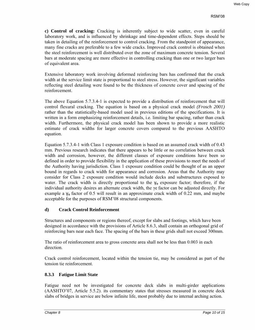
RSM’08
Chapter 8 Page 10 of 15
c) Control of cracking: Cracking is inherently subject to wide scatter, even in careful laboratory work, and is influenced by shrinkage and time-dependent effects. Steps should be taken in detailing of the reinforcement to control cracking. From the standpoint of appearance, many fine cracks are preferable to a few wide cracks. Improved crack control is obtained when the steel reinforcement is well distributed over the zone of maximum concrete tension. Several bars at moderate spacing are more effective in controlling cracking than one or two larger bars of equivalent area. Extensive laboratory work involving deformed reinforcing bars has confirmed that the crack width at the service limit state is proportional to steel stress. However, the significant variables reflecting steel detailing were found to be the thickness of concrete cover and spacing of the reinforcement. The above Equation 5.7.3.4-1 is expected to provide a distribution of reinforcement that will control flexural cracking. The equation is based on a physical crack model (Frosch 2001) rather than the statistically-based model used in previous editions of the specifications. It is written in a form emphasizing reinforcement details, i.e. limiting bar spacing, rather than crack width. Furthermore, the physical crack model has been shown to provide a more realistic estimate of crack widths for larger concrete covers compared to the previous AASHTO equation. Equation 5.7.3.4-1 with Class 1 exposure condition is based on an assumed crack width of 0.43 mm. Previous research indicates that there appears to be little or no correlation between crack width and corrosion, however, the different classes of exposure conditions have been so defined in order to provide flexibility in the application of these provisions to meet the needs of the Authority having jurisdiction. Class 1 exposure condition could be thought of as an upper bound in regards to crack width for appearance and corrosion. Areas that the Authority may consider for Class 2 exposure condition would include decks and substructures exposed to water. The crack width is directly proportional to the γe exposure factor; therefore, if the individual authority desires an alternate crack width, the γe factor can be adjusted directly. For example a γe factor of 0.5 will result in an approximate crack width of 0.22 mm, and maybe acceptable for the purposes of RSM’08 structural components. d) Crack Control Reinforcement Structures and components or regions thereof, except for slabs and footings, which have been designed in accordance with the provisions of Article 8.6.3, shall contain an orthogonal grid of reinforcing bars near each face. The spacing of the bars in these grids shall not exceed 300mm. The ratio of reinforcement area to gross concrete area shall not be less than 0.003 in each direction. Crack control reinforcement, located within the tension tie, may be considered as part of the tension tie reinforcement. 8.3.3 Fatigue Limit State Fatigue need not be investigated for concrete deck slabs in multi-girder applications (AASHTO’07, Article 5.5.2). its commentary states that stresses measured in concrete deck slabs of bridges in service are below infinite life, most probably due to internal arching action.
Web Copy

RSM’08
Chapter 8 Page 11 of 15
The commentary C9.7.2.1 states, “Extensive research into the behavior of concrete deck slabs discovered that the primary structural action by which these slabs resist concentrated wheel loads is not flexure as traditionally believed, but a complex internal membrane stress state referred to as internal arching. This action is made possible by cracking of the concrete in positive moment of the design slab and the resulting upward shift of the neutral axis in that portion of the slab. The action is sustained by in-plane membrane forces that develop as a result of local confinement provided by the surrounding concrete slab, rigid appurtenances, and supporting components acting compositely with the slab.” In regions of compressive stress due to permanent loads and prestress in reinforced and partially prestressed components, fatigue shall be considered only if this compressive stress is less than twice the maximum tensile live load stresses resulting from the fatigue load combination in combination with AASHTO’07, Article 3.6.1.4. Fatigue of the reinforcement need not be checked for fully prestressed components designed to have extreme fiber tensile stress due to Service III Limit State within the tensile stress limit. 8.3.4 Strength Limit State (AASHTO’07, Article 5.5.4) 8.3.4.1 General The strength limit state issues to be considered shall be those of strength and stability. The resistance factor is specified in AASHTO’07, Table 5.5.4.2.2, and is shown below.. 8. 3.4.2 Resistance Factors Resistance factor ф shall be taken as:
• For tension-controlled RC section as defined in AASHTO’07, Article 5.7.2.1 …….0.90 • For tension-controlled PC section as defined in AASHTO’07, Article 5.7.2.1 …….1.00 • For shear and tension:
Normal weight concrete …………………………………………………………0.90 Light weight concrete …………………………………………………………0.70
• For compression-controlled sections with spirals or ties, as defined in AASHTO’07, Article 5.7.4.2.1, except as defined in Article 5.10.11.4.1b for high Seismic Zones at the extreme event limit state ……………………………….0.75
• For bearing on concrete ………………………………………………………………...0.70
• For compression in strut-and-tie models …………………………………………………..…………….0.70
• For compression in anchorage zones:
Web Copy

RSM’08
Chapter 8 Page 12 of 15
Normal weight concrete ……………………………………………………………0.80 Light weight concrete ……………………………………………………………0.65
• For tension in steel in anchorage zones ……………………………………………………..……………..1.00
• For resistance during pile driving …………………………………………………………………....1.00
8.3.4.3 Stability (ref.: AASHTO’07, Article 5.5.4.3) The structure as a whole and its components shall be designed to resist sliding, overturning, uplift and buckling. Effects of eccentricity of load shall be considered in the analysis and design. Buckling of precast members during handling transportation and erection shall be investigated.
8.4 EXTREME EVENT LIMIT STATE (ref.: AASHTO’07, Article 5.5.5) The structure as a whole and its components shall be proportioned to to resist collapse due to extreme events, as may be appropriate to its site and use (ref.: RSM’08, Chapter 6, Article 6.10). 8.5 DESIGN CONSIDERATIONS (ref.: AASHTO’07, Article 5.6) 8.5.1 General Components and connections shall e designed to resist load combinations, as specified in Chapter 6, Article 6.10, at all stages during the life of the structure, including those during construction. Equilibrium and strain compatibility shall be maintained in the analysis, in accordance with AASHTO’07, Section 4. 8.5.2 Effects of Imposed Deformations (ref.: AASHTO’07, Article 5.6.2) The effects of imposed deformations due to shrinkage, temperature change, creep, prestressing, and 8.6 STRUTS-AND-TIE MODEL 8.6.1 General Strut-and-tie models may be used to determine internal force effects near supports and the points of application of concentrated loads at strength and extreme events limit states.
Web Copy

RSM’08
Chapter 8 Page 13 of 15
The strut-and-tie model should be considered for the design of deep beams and pile caps or other situations in which the distance between the centers of applied load and the supporting reactions is less than twice the member thickness. The strut-and-tie model is new to the AASHTO specifications. If the strut-and-tie model is selected for structural analysis, the following Articles of AASHTO’07 will apply:
Article 5.6.3.2 Structural Modeling Article 5.6.3.3 Proportioning of Compressive Struts Article 5.6.3.4 Proportioning of Tension Ties Article 5.6.3.4 Proportioning of Node Regions Article 5.6.3.5 Crack Control Reinforcement
8.6.2 Structural Modeling The structure and a component or region, thereof, may be modeled as an assembly of steel tension ties and compressive struts interconnected at nodes to form a truss capable of carrying all the applied loads to the supports. The required widths of compression struts and tension ties shall be considered in determining the geometry of the truss. 8.7 DESIGNS FOR FLEXURAL AND AXIAL FORCE EFFECTS (AASHTO’07, Article 5.7) 8.7.1 Assumptions for Service and Fatigue Limit States The following assumptions may be used in the design of reinforced, prestressed, and partially prestressed concrete components for all compressive stress levels:
• Pretsressed concrete resists tension at sections that are uncracked, except for direct tension members (AASHTO’07, Article 5.7.6).
• The strains in the concrete vary linearly, except in components or regions of components for which conventional strength of materials is inappropriate.
• The modular ratio, n, is bounded to the nearest integer number. • The modular ratio is calculated as under:
o Es/Ec for reinforcing bars o Ep/Ec for prestressing tendons
• An effective modular ratio of 2n is applicable to permanent loads and prestress.
8.7.2 General Assumptions for Strength and Extreme Event Limit States Factored resistance of concrete components shall be based on the conditions of equilibrium and strain compatibility, and the following assumptions
• In components with fully bonded reinforcement or prestressing, or in the bonded length of locally debonded or shielded strands, strain is directly proportional to the distance from the neutral axis, except for deep members, and for other disturbed regions.
• In components with fully unbonded or partially unbonded prestressing tendons, i.e., not
Web Copy

RSM’08
Chapter 8 Page 14 of 15
locally Debonded or shielded strands, the difference in strain between the tendons and the concrete section and the effect of deflections on tendon geometry are included in the determination of the stress in the tendons.
• If the concrete is unconfined, the maximum usable strain at the extreme concrete compression fiber is not greater than 0.003.
• If the concrete is confined, a maximum usable strain exceeding 0.003 in the confined core ay be utilized if verified. Calculation of the factored resistance shall consider that the concrete cover may be lost at strains compatible with those in the confined concrete.
• Except for the strut-and-tie model, the stress in the reinforcement is based on a stress-train curve representative of the steel or on an approved mathematical representation, including development of reinforcing and prestressing elements and transfer of pretensioning.
• The tensile strength of the concrete is neglected. • The concrete compressive stress-strain distribution is assumed to be rectangular,
parabolic, or any shape that results in a prediction of strength in substantial agreement with he test results.
• The development of reinforcing and prestressing elements and transfer of pretensioning are considered.
• Balanced strain conditions exist at a cross-section when tension reinforcement reaches the strain corresponding to its specified yield strength fy just as the concrete in compression reaches its assumed ultimate strain of 0.003.
• Sections are compression-controlled when the net tensile strain in the extreme tension steel is equal to or less than the compression-controlled strain limit of 0.003. The compression-controlled strain limit is the net tensile strain in the reinforcement at balanced strain conditions. For Grade 420 reinforcement, and for all prestressed reinforcement, the compression-controlled strain may be set equal to 0.002.
• Sections are tension-controlled when the net tensile strain in the extreme tension steel is equal to or greater than 0.005 just as the concrete in compression reaches its assumed strain limit of 0.003. Sections with net tensile strain in the extreme tension steel between the compression-controlled strain limit and 0.005 constitute a transition region between compression-controlled and tension-controlled sections.
• The use of compression reinforcement in conjunction with additional tension reinforcement is permitted to increase the strength of flexural members.
• In the approximate flexural resistance equations of AASHTO’07, Articles 5.7.3.1 and 5.7.3.2, fy and fy’ may replace fs and fs’, respectively, subject t the following conditions:
o fy may replace fs when, using fy in the calculation, the resulting ratio c/ds does not exceed 0.6. If c/ds exceeds 06, strain compatibility shall be used to determine the the stress in the mild steel tension reinforcement.
o fy’ may replace fs’ when, using fy’ in the calculation, c≥d’s. If c<d’s, strain compatibility shall be used o determine the stress in the mild steel compression reinforcement. The compression reinforcement shall be conservatively ignored, i.e., A’s = 0.
Web Copy

RSM’08
Chapter 8 Page 15 of 15
8.8 FLEXURAL MEMBERS (AASHTO’07, Article 5.7.3) 8.8.1 Stress in Prestressing Steel at Nominal Flexural resistance
• For components with bonded tendons, refer to AASHTO’07, Article 5.7.3.1.1.
Web Copy

RSM’08
Chapter 9 Page 1 of 38
CHAPTER 9
SUPERSTRUCTURE 9.1 RC DECK 9.1.1 Design philosophy The structural design of the deck slab depends mainly on the spacing of the main and cross-girders and the cantilever overhangs on either end of the deck. The design has been done mainly based on AASHTO 2007. For more accurate design, the following analysis and design methods are recommended:
• AASHTO “Approximate Methods of Analysis” (AASHTO 2007, Art. 4.6.2) • AASHTO “Refined Methods of Analysis” (AASHTO 2007, Art. 4.6.3) • AASHTO “Empirical Design” Methods (AASHTO 2007, Art. 9.7.2) • Yield line analysis • Hillerborg strip method • Pucher's chart
9.1.2 Material strength For material specifications and various classes of concrete Chapter 7 of this Manual is referred. Cement has been specified based on Bangladesh Standard BDS EN 197-1, issued April 2003, and reinforcing steel has been specified based on BDS 1313: 1991.
9.1.3 RC railing, sidewalk and curb 9.1.3.1 Railing and rail post a) General Curb height has been provided 300 mm above concrete deck surface, and 250 mm above wearing course. It’s assumed that this curb will prevent wheel loads from mounting over the deck overhang. Therefore, pedestrian railings have been considered at the edges of structure for protection against pedestrian traffic. Two types of railings are provided: Type A Cast-in-place railing and Type B Precast railings. Precast railing is provided to achieve better aesthetic look and good finish. The railings have been designed for load specified by AASHTO’07, Art. 13.8. The height of the railing shall be minimum 1060 mm measured from the top of the walkway. b) Rail Post For design of rail post horizontal live load for each post shall be PLL = 0.89 + 0.73L in kN, acting at the center of gravity of topmost rail level,
Web Copy
RSM’08
Chapter 9 Page 2 of 38
where, L = post spacing in m. Each longitudinal element will be designed for 0.73 kN/lm, both transversely and vertically, acting simultaneously, plus a concentrated load of 0.89 kN as above shall be considered at the center of gravity of the member specified by AASHTO 2007, Art. 13.8.2 & Fig.13.8.2.1. Ultimate moment capacity of the rail post has been checked at the base level of post.
c) Rail bar The design live load for pedestrian railing shall be taken as w = 0.73 N/mm, both transversely and vertically, acting simultaneously. In addition, each longitudinal element will be designed for a concentrated load of 890 N, which shall act simultaneously with the above loads at any point and in any direction at the top of the longitudinal element specified by AASHTO 2007, Art. 13.8.2. Ultimate capacity of the rail bar has been checked against maximum factored moments.
9.1.3.2 Sidewalk Sidewalk has been designed for a live load of 3.6 x 10⁻³ MPa pedestrian load specified by AASHTO’07, Art. 3.6.1.6. As required by AASHTO’07, Article 3.6.1.3.4, live load moment over deck overhang not exceeding 1800 mm, one line load of 14.6 kN/lm located at 300 mm from the face of the railing is to be considered.
9.1.3.3 Curb The curb has been designed to resist a lateral force of not less than 7.00 kN/lm length of the curb and applied at the top of it. 9.1.3.4 Design of deck slab The AASHTO’07 design methods of RC deck slab for both reinforced and prestressed bridges is given in Chapter 8 Concrete Structures. It covers the design requirements based on the limit states, comprising service, strength and fatigue limit states. Chapter 6 Design codes, standards and loads give the provisions for design live loads including dynamic load allowances, IM, multiple presence of live loads, pedestrian loads, shrinkage, creep, load combinations, load factors and impact for different classes of strength, service, fatigue, and extreme events, based on AASHTO’07. Article 9.1.4 gives the flow chart for design of deck slab.
Web Copy

RSM’08
Chapter 9 Page 3 of 38
9.1.4 Flow Chart for Design of Deck Slab
Start
Select deck type : Type IA, Side Walk 875mm, cant-in-Place railing, out to out deck width 8,260mm. Type IB, side walk 750mm, precast railing. Side Walk 750 mm, out to out deck width 7,760mm; Type IIA, side walk 625mm, cant-in-place railing, out to out desk width 7,760mm & out to out deck width 7,760mm & Type IIB, side walk 500mm, precast railing, out to out deck width 7,760mm. Carriageway for all types 6010mm. 4 main girders, 2 end cross girders & 1 intermediate cross girders @ 12,000mm for spans > 12,000. Cross slope 3.0%.
Select main girder spacing such that for the deck slab, -ve and +ve M over the interior girders and the -ve M for the overhang over the exterior girder can be kept nearly equal; assume deck slab thickness “h” = or > 175mm, which is the minimum thickness required from consideration of deflection (Ref: AASHTO 2007, Art. 9.7.1.1).
Select material strength: for concrete fc’ = 20 & 25 Mpa; HY reinforcing steel, fy = 275 & 400 MPa (Ref: for details. Dwg. No. PC-GN-00 General Notes).
Calculate for the interior span, unfactored dead load moment, for deck concrete +ve MDLIS1 = +ve MDLIS2 = (wd * S2/8 in kNm/lm, & + MDLIS2 = +ve MDLlS2 = (wac* S2/8) kNm/lm, where wd = unit load due to self weight of deck concrete in kN/m2, wac = unit load due to self weight of asphaltic concrete wearing course in kN/m2, and S = clear spacing between monolithic girder webs ignoring fillet in m (Ref. AASHTO 2007, Art. 9.7.2.3).
Calculate for interior span, for Live Load under service condition, maximum +ve & -ve M, MLLlS = [{(Pwheel/Bstrip) * S/8} + {(9.3/3.00) * (S/1000)2/8}] in kN/Im, where Pwheel = 72.25 kN, Bstrip & S as above in mm (Ref. AASHTO 2007 Art. 4.6.2.1).
Calculate for the deck overhang, the maximum -ve dead load B.M. over the exterior girder under service condition, -MDLoverhang1 due to overhang deck concrete, dead load due to sidewalk concrete & curb, and rail & rail post, and -MDLoverhang2 due to asphaltic concrete wearing course.
For deck overhang <1800mm, consider one line load of PLL1 = 14.6 kN/1m located at 300mm from the face of the railing, which gives lever arm La1 = (LFP-0.30) in m (Ref. AASHTO 2007, 3.6.1.3.4). In addition, consider the concentrated design horizontal live load on each post, PLL = 0.89 + 73L in kN, acting at the c.g. of topmost rail level, La2 = Zrailtop (Ref. AASHTO 2007, Art. 13.8.2 & Fig. 13.8.2.1). Simultaneously, consider the pedestrian live load FPLL2 = (3.60 * LFP) in kN/lm, where L = post spacing in m, Xl = Distance from the CL of the exterior girder to the line of action of the 14.60 kN/lm line load; Zrail1 = height to the c.g. of the top rail fro the deck concrete surface + h/2; and X2 = distance from the CL exterior girder to the half width of the sidewalk. This gives the service live load moments over the exterior girder: -MFPLL1 = -FPLL1*La1; -MPLL= -PLL1*La2 = -(14.6 * Zrailtop); -MFPLL2 = -FPLL*X2. This gives for the exterior girder, the maximum service Live load M, -MNEGLL overhang = -(MFPLL1 + MFPLL2 + MPLL+ MFPLL2).
Calculate for the deck overhang, the maximum -ve dead load B.M. over the exterior girder under service condition, -MDLoverhang1 due to overhang deck concrete, dead load due to sidewalk concrete & curb, and rail & rail post, and -MDLoverhang2 due to asphaltic concrete wearing course.
1
Web Copy

RSM’08
Chapter 9 Page 4 of 38
Calculate the dynamic load allowance IM = 0.33 (Ref: AASHTO 2007, Table 3.6.2.1-1).
Calculate factored +ve Design B.M. (+MDES = MPOS) MPOS = 1.25 8 MDLIS + 1.75 * MLLIS (1 + 1M), (Ref: AASHTO, 2005, Table: 3.4.1-11). Similarly, factored –ve Design B.M. (-MDES = MNEG) MNEG = 1.25 * MDLIS + 1.75 * MLLIS (1+1M).
Calculate the dynamic load allowance IM = 0.33 (Ref: AASHTO 2007, Table 3.6.2.1-1).
Calculate for the interior girder, the factored +ve Design M (+MDES = MPOS) & -ve Design M (-MDES = MNEG)
MPOS = MNEG = 1.25 * MDLIS1 + 1.75 * MDLIS2 + MLLIS (1 + 1M). (for load factor, refer to AASHTO, 2007, Table : 3.4.1-1).
Similarly calculate for the deck overhang, the factored –ve design M, -MDESoverhang = -(1.25 * MDLoverhang1 + 1.50 * MDLoverhang2 + 1.75 * MLLoverhang).
Design railing & rail post using 7.30 kN/1m loading both horizontally and vertically and vertically.
Assume reinforcement dia.in.mm, spacing in mm and area in mm2.
Calculate lever arm factor, a = (As*fy)/(0.85*fc’*b), where As = area of tension reinforcement in mm2, fc’, fy = as given above, & b = width of the section at N. A.
Calculate moment capacity ØMn = 0.9 * As fy (d-a/2)
Is Ø Mn >= ± MDES
Optimize ‘h’, Re-select
H=200mm (say)
Slab thickness ‘h’ and Reinforcement for flexure is OK (Ref:
AASHTO 2007, Art. 9 7 0 2)
A 2
1
Web Copy
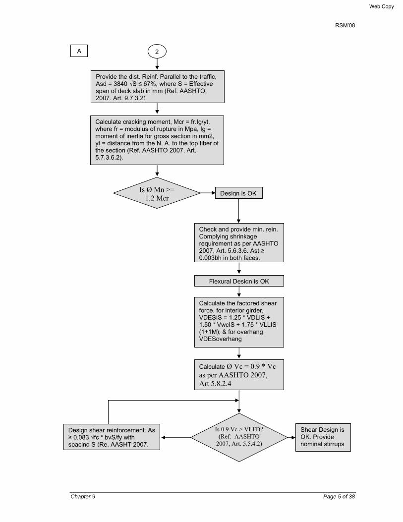
RSM’08
Chapter 9 Page 5 of 38
A 2
Provide the dist. Reinf. Parallel to the traffic, Asd = 3840 √S ≤ 67%, where S = Effective span of deck slab in mm (Ref. AASHTO, 2007, Art. 9.7.3.2)
Calculate cracking moment, Mcr = fr.Ig/yt, where fr = modulus of rupture in Mpa, Ig = moment of inertia for gross section in mm2, yt = distance from the N. A. to the top fiber of the section (Ref. AASHTO 2007, Art. 5.7.3.6.2).
Is Ø Mn >= 1.2 Mcr
Design is OK
Check and provide min. rein. Complying shrinkage requirement as per AASHTO 2007, Art. 5.6.3.6. Ast ≥ 0.003bh in both faces.
Flexural Design is OK
Calculate the factored shear force, for interior girder, VDESIS = 1.25 * VDLIS + 1.50 * VwcIS + 1.75 * VLLIS (1+1M); & for overhang VDESoverhang
Calculate Ø Vc = 0.9 * Vc as per AASHTO 2007, Art 5.8.2.4
Is 0.9 Vc > VLFD? (Ref: AASHTO
2007, Art. 5.5.4.2)
Design shear reinforcement. As ≥ 0.083 √fc * bvS/fy with spacing S (Re. AASHT 2007,
Shear Design is OK. Provide nominal stirrups
Web Copy

RSM’08
Chapter 9 Page 6 of 38
9.2 RC GIRDER 9.2.1 Design of RC girder Like deck slab, Chapter 8 Concrete Structures, covers the design requirements, based on the limit states philosophy, namely, service, strength and fatigue limit states. Chapter 6 Design codes, standards and loads give the provisions for design live loads including dynamic load allowances, IM, multiple presence of live loads, pedestrian loads, shrinkage, creep, load combinations, load factors and impact for different classes of strength, service, fatigue, and extreme events, based on AASHTO’07. Article 9.2.1-1 gives the flow chart for design of deck slab.
Web Copy

RSM’08
Chapter 9 Page 7 of 38
9.2.1-2 FLOW CHART FOR DESIGN OF RC GIRDER
Start
Select span Deck geometry (Refer to Deck Flow Chart, Art. 9.1.4 above)
Select material strength and properties for deck and cross girder Concrete fc' = 20 / 25 MPa Reinforcig steel fy = 275 & 400 MPa (Ref. Dwg. No. PC-GN-00 General Notes)
Select type of girder - Rectangular section No.of girders – 4, and dimensions as shown on drawings No.of cross girders – 1 at each girder end, and 1 intermediate for spans>12.00 m, 2 for spans between 25.00 and 36.00 m, and 3 for spans > 36.00 m.
Design deck slab (Refer to deck flow chart, article 9.1.4)
Design RC girder
Web Copy
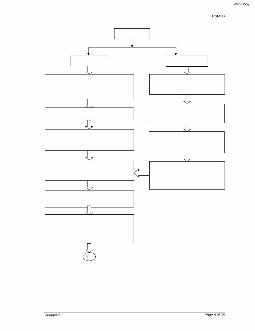
RSM’08
Chapter 9 Page 8 of 38
RC Girder
Interior Exterior
Calculate dead load: self weight deck wD, self weight girder wG, self weight x-girder wC.G, & self weight wearing course wwc KN/m
Calculate moment, MD for wD, MG for wG, MC.G. for wC.G & MWC for wwc
Place wheel load for maximum bending moment & calculate max truck load moment, MLL, kN-m.
Calculate impact moment using factor .IM = 0.33 (Ref: AASHTO 2007, Table 3.6.2.1-1)
Calculate MLL+ IM*MLL = MLL (1+IM). Also calculate lane load moment, MLANE
Calculate MDES = 1.25MD +1.5MC+1.75MLL (1 + IM) + 1.75 MLANE (Ref: For load factor, AASHTO, 2007, Table 3.4.1-1)
Calculate Dead loads for deck projection, footpath, Kerb, railing, & rail post
Calculate effective span, s = distance between girder edge & deck end
Calculate DL Moment, MD for all dead load except wearing course and wearing course moment MWC
For curb height 250mm above WC, place wheel at 300 mm from curb edge. Calculate MLL (1 + IM) + MLANE (AASHTO’07, Art.-3.6.1)
1
Web Copy
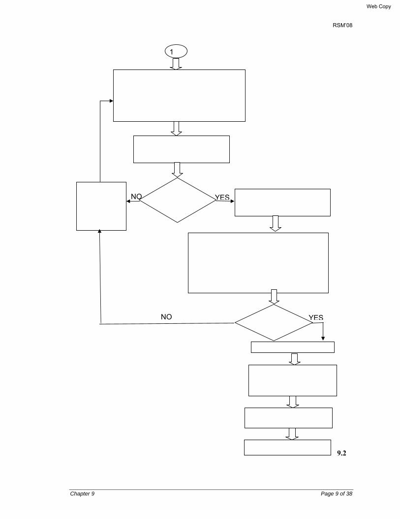
RSM’08
Chapter 9 Page 9 of 38
9.2
Calculate lever arm factor, a = (Asfy)/(0.85fc'b), where As = area of reinforcement in mm2, fc', fy as given & b = width of the section at neutral axis N.A.
Calculate moment capacity ØMn = 0.9Asfy(d-a/2)
Re select girder section and/or Reinforcement dia/ area
Girder section and reinforcement calculation is O.K
Calculate cracking moment, Mcr = fr.Ig/yt, where fr = modulus of rupture in Mpa, Ig = moment of inertia for gross section in mm², yt = distance from the N. A. to the top fiber of the section.(Ref. AASHTO 2007, Art. 5.7.3.6.2).
Flexure design is O.K
Calculate Vu and Ø Vc , Ø = 0.9, as per AASHTO 2007, Art. 5.8.2.4
Calculate minimum spacing of stirrup
Provide nominal stirrup
1
Is φMn > ± MDES
Is Ø Mn > 1.2 Mcr?
NO YES
NO YES
Web Copy
RSM’08
Chapter 9 Page 10 of 38
9.2.2 Construction of RC girder 9.2.2.1 General The bridge structures of this Manual will be constructed mainly in the remote rural areas. The country is riverine where early monsoon flood is likely to occur. This makes the construction period short. The construction methodology adopted for the bridge superstructure should keep this into consideration. The spans for the RC deck girder bridges of this Manual vary between 12.00 and 25.00m c/c bearings, for which both the deck and the girders will be cast-in-situ construction. The following sections give details of the appropriate construction methodology of components of the superstructure. 9.2.2.2 Construction methodology of the RC girder and deck slab 9.2.2.3 Conventional method Most of these bridges are river bridges. For many of these rivers bed level becomes dry during the winter seasons. But the river bed material for some depth below the bed comprises poor bearing capacity. The conventional method of construction generally comprises driving of reasonably straight sal ballah piles of girth about 150mm diameter at 1/3rd depth from its narrow end. The tapered end of the piles is driven below ground level. 140 kg hammer/money with height of fall about 760 mm is used to drive these piles to refused level. The Engineering News Record formula will be used to calculate the ultimate bearing capacity of these piles. To calculate the allowable bearing capacity of the individual piles, the factor of safety will be used about 6. The spacing and number of the sal ballah piles will be decided based on the weight of the green concrete of the cast-in-situ girder and deck each pile will be designed to carry depending upon its allowable bearing capacity. A platform will be erected over these piles either using steel joists or timber of adequate size and strength. It will be in horizontal grids. The vertical props preferably of MS pipes of diameter about 150mm and spacing as required depending upon the allowable load carrying capacity of these props will be used. The props will be designed mainly for the axial compressive load. The allowance shall be kept for the initial eccentricity of these props. Adequate horizontal and diagonal bracing shall be provided to carry the horizontal forces due to the wind load and the temporary live load including the construction equipment. The provision shall be kept assuming the construction equipment may hit the props. The bracing system should be able to carry minimum 25% of the vertical load in the horizontal direction. To keep the slenderness ratio within reasonable limits, the vertical spacing of these bracings shouldn’t exceed 2.50 – 3.00m. The top level horizontal bracing should be placed about 300mm from the top level of the props. The steel props have advantages that height adjustment provisions can be accommodated at its top and bottom easily.
In this method of construction the formwork for the girders and the deck are to be placed simultaneously.
Web Copy

RSM’08
Chapter 9 Page 11 of 38
9.2.2.4 Recommended methods of construction
It’s advisable not to construct the bridge superstructure erecting props on the river bed, as the bed materials are generally constituted of soft soil, as stated earlier. Its bearing capacity is generally poor and the props erected therein are susceptible to differential settlement, which are likely to affect the green concrete. In the extreme condition, the scaffolding may fail in case of onrush of sudden floods, or storms, etc.
The alternative is to adopt the composite construction method, in which the girders will be made precast and the deck will then be constructed by erecting formwork supported over the precast girders through inserts. The deck concreting will be done after girder concrete gains adequate strength. The girders may be constructed at some convenient location over the piers. This will then be lifted and shifted in position over the bearings, after it gains sufficient strength.
The standard girders of this Manual will need some design check and modifications before use. The girder web will then behave as a rectangular beam for its self weight and the green concrete of the deck. The composite behavior will be achieved for the superimposed dead load and the live load only. The stirrups will also need to be checked as shear connectors. The creep modified shrinkage, differential shrinkage; and creep effect will then also need to be checked.
The major benefit of this method of construction will be that for girder concreting it will be possible to erect steel trusses supported over the abutments/piers. The contractor will then be able to continue the construction uninterrupted during the monsoon seasons also.
What the contractor is to do in this case is that he has to take the help of an experienced designer to provide the technical support in this regard. The standard design of this bridge keeps provision in the substructure and foundations to carry the additional load which will generate due to the design modifications.
9.3 PC GIRDER 9.3.1 Design of PC girder
9.3.1.1 Design philosophy AASHTO'07 requires that the prestressed and partially prestressed concrete structural components shall be designed for both initial and final prestressing forces. These shall be proportioned to satisfy the requirements at all appropriate service, fatigue, strength, and extreme events limit states. (Ref.: Chapter 8 Concrete Structures). These components shall be investigated for stresses and deformations for each stage that may be critical during construction, stressing, handling, transportation, and erection as well as during the service life of the structure of which they are part. Stress concentrations due to prestressing or other loads and to restraints or imposed deformations shall be considered (Ref.: AASHTO’07, Art. 5.5). 9.3.1.2 Service limit state
AASHTO’07, Article 5.5.2 requires that actions to be considered at the service limit state shall be cracking, deformations, and concrete stresses in accordance with its articles 5.7.3.4, 5.7.3.6,
Web Copy

RSM’08
Chapter 9 Page 12 of 38
and 5.9.4). The cracking stress shall be taken as the modulus of rupture specified in AASHTO’07, Article 5.4.2.6 (For details refer to Article 8 Concrete structures). 9.3.1.3 Span length and overall length The effective span length of simply supported girders shall be center to center bearings but shall not exceed the clear span plus the depth of the girder. Extra length is to be provided beyond center line bearing at each end. Thus overall length of the girder is center to center bearing span plus twice the end projection. 9.3.1.4 Effective compression flange width for composite T-girder For composite prestressed concrete construction where slabs or flanges are assumed to act integrally with the girder, the effective flange width shall conform to the following:
a) The total width of slab effective as a T-girder flange shall not exceed one-fourth of the span length of the girder. The effective flange width overhanging on each side of the web shall not exceed six times the thickness of the slab, or one half the clear distances to the next web.
b) For girder having a slab on one side only, the effective overhanging flange width shall not exceed 1/12 of the span length of the girder, six times the thickness of the slab, or one-half of the clear distance to the next web.
c) If the concrete strength of the PC girder and the deck slab are different, then the above flange width will be multiplied by a correction factor = Ec,de(.k) / Ec(gjrd(.r) to get the effective flange width.
9.3.1.5 Deflection
Deflection calculations shall consider dead load, live load, prestressing, erection loads, concrete creep, shrinkage and steel relaxation. 9.3.1.6 Composite flexural member
Composite flexural members consist of precast and/or cast-in-place concrete elements constructed in separate placements but so interconnected that all elements respond to superimposed loads as a unit. The design shall provide for full transfer of horizontal shear forces at contact surface of interconnected elements. In structures with a cast-in-place slab on precast girders, the differential shrinkage tends to cause tensile stresses in the slab and in the bottom of the girder. Because the tensile shrinkage develops over an extended time period, the effect on the girder is reduced by creep. Differential shrinkage may influence the cracking load and the girder deflection profile. When these factors are particularly significant, the effect of differential shrinkage should be added to the effect of loads.
Web Copy

RSM’08
Chapter 9 Page 13 of 38
9.3.1.7 Allowable stresses The stress-relieved low relaxation high tensile (HT) steel strands (7-wire 12.7 mm diameter), are used in the design for the post-tensioned girders. AASHTO’07, Table 5.9.3-1 gives the following stress limits for the above tendons: a) Prestressing steel for Post-Tensioned Members
All units are in N/mm Immediately prior to transfer (fpbt) = 0.75 fpu At service limit state after all losses (fpe) = 0.80 fpy Prior to seating – short term fpbt may be allowed = 0.90 fpy At anchorages immediately after anchor set = 0.70 fpu Elsewhere along length f member away from anchorages immediately after transfer = 0.74 fpu
b) Concrete
i) Temporary tensile stress limits in prestressed concrete before losses, fully prestressed components (AASHTO’07, Table 5.9.4.1.2-1):
• In areas other than the precompressed tensile zone and without bonded reinforcement = 0.25√f’ci ≤ 1.38 MPa
• In areas with bonded reinforcement (reinforcing bars or prestressing steel) sufficient to resist the tensile force in the concrete computed assuming an uncracked section, where reinforcement is proportioned using a stress of 0.5 fy, not to exceed 210 MPa = 0.63√f’ci.
ii) Compressive stress limits in prestressed concrete at service limit state after all losses, fully prestressed components (AASHTO’07, Table 5.9.4.2.1-1):
• In other than segmentally constructed bridges due to the sum of effective prestress and permanent loads = 0.45f’c
• In other than segmentally constructed bridges due to live load and one-half the sum of effective prestress and permanent loads = 0.40f’c
• Due to the sum of effective prestress, permanent loads, and transient loads and during shipping and handling = 0.60фwf’c.
iii) Tensile stress limits in prestressed concrete at service limit state after losses, fully
prestressed components (AASHTO’07, Table 5.9.4.2.2-1): Tension in the precompressed tensile zone bridges, assuming uncracked sections
• For components with bonded prestressing tendons or reinforcement that are subjected to not worse than moderate corrosion conditions = 0.50√f’c
• For components with bonded prestressing tendons or reinforcement that are subjected to severe corrosion conditions = 0.25√f’c
Web Copy
RSM’08
Chapter 9 Page 14 of 38
9.3.2 Loss of prestress 9.3.2.1 Total loss of prestress There are several factors which cause the force in the prestressing cables to fall from the initial force imparted by the jacking system. Some of these losses are immediate, affecting the prestressing force as soon as it is transferred to the concrete member. Other losses occur gradually with time. The items which fall under the immediate and long term losses for post-tensioned members are given in Table 9.3.2.1-1 below.
Table 9.3.2.1-1 Prestress losses
Immediate Long-term
Elastic Shortening Friction Anchorage/Wedge Pull-in
Concrete long-term Shrinkage Concrete Creep Steel Relaxation
In lieu of more detailed analysis, prestress losses in members constructed and prestressed in a single stage, relative to the stress immediately before transfer, may be taken based on AASHTO 2007, Art. 5.9.5, as: • In pretensioned members:
∆fpT = ∆fpES + ∆fpLT (9.3.8.1-1)
• In post-tensioned members (AASHTO 2007, Article 5.9.5.1):
∆fpT = ∆fpF + ∆fpA + ∆fpES + ∆fpLT (9.3.8.1-2)
where, ∆fpT = total loss (MPa) ∆fpF = loss due to friction (MPa) ∆fpA = loss due to anchorage set (MPa) ∆fpES = sum of all losses or gains due to elastic shortening or extension at the time
of application of prestress and/or external load ∆fpLT = losses due to long term shrinkage and creep of concrete, and relaxation of
steel (MPa)
9.3.2.2 Immediate Losses
(i) Elastic Shortening, ∆fpES For Post-tensioned members,
∆fpES = {(N – 1)/N}(Ep/Ect) fcgp (9.3.8.1-3)
Web Copy
RSM’08
Chapter 9 Page 15 of 38
where,
N = number of identical prestressing tendons fcgp = sum of concrete stresses at the center of gravity of prestressing tendons due to the
prestressing force after jacking and the self weight of he member at the sections of maximum moment (MPa).
fcgp values may be calculated using a steel stress reduced below the initial value by a margin dependent on elastic shortening, relaxation, and friction effects. For post-tensioned structures with bonded tendons, fcgp may be taken at the center of the span or, for continuous construction, at the section of maximum moment.
Ep = Modulus of elasticity of prestressing steel, kN/mm2 ECt = Modulus of elasticity of concrete in kN/m2 at transfer or time of load application, MPa,
calculated from: EC = 0.043 K1 γc
1.5√f’c (9.3.8.1-4)
where,
K1 = correction factor for source of aggregate to be taken as 1.0 unless determined by physical test and approved by the Authority.
For normal density concrete with γc = 2320 kg/m3 , EC may be taken as EC = 4800 √f’c (9.3.8.1-4)
To determine the value of ECt, use the expression ECt = 4800 √f’ci
where,
f’ci = concrete cylinder compressive strength at the time of transfer (MPa) (ii) Friction losses (AASHTO 2007, Article 5.9.5.2.2): Losses due to friction between the internal prestressing tendons and the
duct wall may be taken as:
∆fpF = fpj (1 – e-(kx + µα)) (9.3.8.1-5)
where, fpj = steel stress at jacking end (MPa) x = length of a prestressing tendon from the jacking ed to any point
under consideration (mm) K = wobble friction coefficient (per mm of tendon) Μ = coefficient of friction α = sum of the absolute values of angular change of prestressing steel
path from jacking end, or from the nearest jacking end if tensioning is done equally at both ends, to the pint under investigation (rad.)
e = base of Napierian logarithms.
Values of K and µ should be based on experimental data for the materials specified and shall
Web Copy

RSM’08
Chapter 9 Page 16 of 38
be shown on the contract documents. In the absence of such data, a value within the ranges of K and µ specified in Table 9.3.2.2-1 below.
Table 9.3.2.2-1 Friction coefficients for pos-tensioning tendons (AASHTO 2007, Table 5.9.5.2.2b-1)
Type of steel Type of duct K µ Wire or strands Rigid and semirigid galvanized metal shea 6.6 x 10⁻⁷ 0.15-0.25
Polyethylene 6.6 x 10⁻⁷ 0.23 Rigid steel pipe deviators for external tendons
6.6 x 10⁻⁷ 0.25
High strength bars Galvanized metal sheathing 6.6 x 10⁻⁷ 0.30 (iii) Anchorage set/Wedge pull-in losses (AASHTO 2007, Article 5.9.5.2) The magnitude of the anchorage set or wedge pull-in shall be the greater of that required t control the stress in the prestressing steel at transfer or that recommended by the manufacturer of the anchorage. The magnitude of the set assumed for the design and used to calculate set loss shall be shown in the contact documents and verified during construction. Anchorage set loss is actually caused by the movement of the tendon prior to seating of the wedges or the anchorage gripping device. The magnitude of the minimum set depends on the prestressing system used. This loss occurs prior to transfer and causes most of the difference between jacking stress and stress at transfer. A common value for anchor set is 10 mm, although values as low as 1.6 mm are more appropriate for some anchorage devices, such as those for bar tendons. For wedge-type strand anchors, the set may vary between 3 and 10 mm, depending on the type of equipment used. For short tendons, a small anchorage seating value is desirable, and equipment with power wedge seating should be used. For long tendons, the effect of anchorage set on tendon forces is insignificant, and power seating is not necessary. The 6 mm anchorage set value, often assumed in elongation computations, is adequate but only approximate. Due to friction, the loss due to anchorage set may affect only part of the prestressed member. Loss of prestress force due to friction per unit length p = T1 (l-exp(-(µ/r+K)) where, r = radius of curvature of cable = L2/8dr in which ‘L’ is the total length of girder and 'dr' is cable sag at mid span Loss of prestress due to wedge pull-in
∆fwp = (∆wp/ lwp) Eps Aps
Web Copy

RSM’08
Chapter 9 Page 17 of 38
Where, ∆wp = Length of wedge pull-in. usually 6mm for 7-12.7 mm dia. HT 7-wire strand
anchorage system. Eps = Modulus of elasticity of HT wires/strands Aps = Area of HT wires/cable
Length of cable subjected to prestress loss due to wedge pull- in and consequent reverse friction. lwp = (∆wp Eps Aps/ p) ½
Fig. 9.1 Loss of Prestress Due to Friction and Wedge Pull-in
9.3.2.3 Long term losses
The provisions of this Article are based on ‘Approximate Estimate of Time-Dependent Losses’ of AASHTO 2007, Article 5.9.5.3. These are better applicable for standard pretensionsed members. For post-tensioned members, ‘Refined Estimates of Time-Dependent Losses’ of AASHTO 2007 may be followed. (Refer to Article 9.3.8.3). For standard precast, pretensioned members subject to normal loading and environmental conditions, where:
o members are made from normal density concrete, o the concrete is either steam-cured or moist-cured, o prestressing is by bars or strands with normal and low relaxation properties, and o average exposure conditions and temperatures characterize the site,
the long term prestress loss, ∆pLT, due to creep of concrete, shrinkage of concrete, and relaxation of steel shall be estimated using the following formula: ∆pLT = 10.0 (fpi Aps/Ag) γh γst + 83γh γst + ∆fpR (9.3.8.2-1)
Web Copy

RSM’08
Chapter 9 Page 18 of 38
(a) Shrinkage Loss, ∆fSH
Loss of prestress due to shrinkage in post-tensioned members is calculated by using the following equation:
∆fSH = 83γh γst
(b) Creep Loss, ∆fCR Creep Loss in post-tensioned members is calculated as follows: ∆fCR = 10.0 (fpi Aps/Ag) γh γst
(c) Loss due to relaxation of steel, ∆fpR
in which, ∆fSH = Loss of stress due to shrinkage (MPa)
γh = 1.7 – 0.01 H
γst = 35/(7 + f’ci) where,
fpi = prestressing steel stress immediately prior to transfer (MPa) H = the average annual ambient relative humidity in per cent γh = correction factor for relative humidity of the ambient air γst = correction factor for specified concrete strength at time of prestress
transfer to the concrete member ∆fpR = an estimate of relaxation loss taken as 17 MPa for low relaxation strand,
70 MPa for stress relieved strand, and in accordance with manufacturers recommendation for other types of strand (MPa)
The losses or gains due to elastic deformations at the time of transfer or load application should be added to the time dependent losses to determine the total losses.
9.3.2.4 Refined estimate of long term losses (AASHTO 2007, Article 5.9.5.4) The long term prestress losses for the post-tensioned members may be estimated in a refined manner following the procedure given in AASHTO 2007, Article 5.9.5.4). The items of the total long term prestress losses shall be as under:
∆fpLT = (∆fpSD + ∆fpCD +∆fpR2 - ∆fpSS)df
where, ∆fpSD = prestress loss due to shrinkage of girder concrete between time of deck placement and final time (MPa)
∆fpCD = prestress loss due to creep of girder concrete between time of deck placement and final time (MPa)
∆fpR2 = prestress loss due to relaxation of prestressing strands in composite section between time of deck placement and final time (MPa)
∆fpSS = prestress gain due to shrinkage of deck in composite section (MPa).
Refer to Appendix – 9.3.3.3-1 for further details in calculation of losses.
Web Copy

RSM’08
Chapter 9 Page 19 of 38
9.3.3 Losses for deflection calculation (AASHTO 2007, Article 5.9.5.5) For camber and deflection calculations of prestressed nonsegmental members made of normal concrete with a strength in excess of 24 MPa at the time of prestress , ∆fcgp and ∆fcdp may be computed as the stress at the center of gravity of prestressing steel averaged along the length of the member.
9.3.4 Cable elongation In post-tensioned members cable elongation is calculated by using the following formula:
)01.01( ESEALP
psps
av +=∆
where, ∆ = Cable elongation in mm. PaV = Average prestressing force(N) between jacking end and passive end of a
cable for stressing from one end and between jacking end and mid span for a cable stressing from both ends.
L = Length of cable (mm) for which average prestressing force is calculated. An additional length known as jacking length is to be added. APS = Area of prestressing cable in mm2.
Eps = Modulus of elasticity of prestressing steel in N/mm2.
ES = Elastic shortening loss in per cent.
Web Copy

RSM’08
Chapter 9 Page 20 of 38
9.3.5 Flow Chart for design of PC girder
a) Flow Chart: Preliminary works for design of PC Girder
Start
Select - span - deck geometry e.g., carriageway, footpath, curb, railing, rail post, cross lope, wearing course (WC), etc.
Select material strength and properties for deck and cross-girder -concrete fc’ -reinforcing steel fy
Select -type of PC Girder I-section T-section -no. of main and cross-girder, spacing and x-sec
Assume deck slab thickness Design deck slab by using Pucher’s chart/yield line theory/AASHTO simplified method
Flow Chart 2 Steps for design of PC Girder
Web Copy

RSM’08
Chapter 9 Page 21 of 38
b) Flow Chart 2: Steps for Design of PC Girder
PC Girder
Select girder x-sec. for particular span from - AASHTO Standard girder x-sec - PCI Standard girder x-sec - ROIP, FRIP Standard girder x-sec
- Manual on PC Bridges, 1996
Select material properties -concrete strength fc’ for girder concrete -prestressing steel conforming to ASTM A421-80 (85) HT 7-wire strand -diameter, As -tensile strength, fs’ -yield strength, fy -type of cable: 7 No. 12.7 mm dia. Select method of prestressing -post tensioned
Select Design Code; AASHTO ‘07
Select -no of cables -cable layout at mid-span and end span -cable profile, and ordinates at mid-span and girder end (at girder-end cable eccentricity should be nearer to zero) -sheath diameter for prestressing cables -cable eccentricity -clear cover
Calculate section properties for Non composite girder x-sec -gross area -net area deducting ungrouted duct holes for post-tensioned concrete -depth from net area to girder top and bottom -second moment of area -section modulus.
1
Web Copy

RSM’08
Chapter 9 Page 22 of 38
1
Calculate section properties for Composite section -effective flange width, bf -gross area; Acomp -net area deducting ungrouted duct holes for post- tensioned concrete, if any -depth from net area to girder, deck top and girder bottom, Ytc, Yts, Ybc -second moment of area -section modulus; Ztc, Zts, Zbc
At mid-span calculate bending moment due to self weight of girder; fb1 & fb2. fb1=M/Zb; fb2=M/Zt Calculate stresses
Assume stage 1 prestressing force, NP and eccentricity, e Calculate fb2= NP/Anoncomp + NPe/Zb
ft2 = NP/Anoncomp –Npe/Zt
Calculate loss of prestress fb3, ft3 due to friction, wedge pull-in, elastic shortening, relaxation loss (100 hrs.) at mid-span
Calculate sub-total fb4=fb1+fb2+fb3,ft4=ft1+ft2+ft3 Check adequately fb≤0.55 and ft≤0.249√fc’
Shift the girder and place in position. Stage 2 prestressing may then be done before concreting of cross-girder and deck slab depending upon the concrete strength of PC girder gained, if required.
Calculate loss of prestress fb6 &ft6 due to friction, wedge pull-in, elastic shortening and relaxation loss (100/1000 hrs)
2
Calculate sub-total 2 of stresses and check adequacy up to this stage fb7=fb4+fb5+fb6 , ft7=ft4+ft5+ft6
Web Copy

RSM’08
Chapter 9 Page 23 of 38
2
Calculate bending moment due to x-girder at mid-span Calculate fb8, ft8
Calculate bending moment due to deck concrete at mid-span Calculate fb9, ft9 and fts1
For AASHTO HL93 loading, Calculate load intensity on the interior and exterior girders by simplified AASHTO method (AASHTO”07) or load distribution analysis at mid-span
Calculate bending moment due to live load at mid-span Calculate fbc2, ftc2 & fts3.
Calculate axial force and bending moment due to creep-modified differential shrinkage due to cast-in-situ deck concrete at midspan Calculate stresses, fbc3, fbc3, fts4 (AASHTO’07)
Calculate remaining losses fbc4, ftc4, fts5 due to prestressing after Stage 2 at mid-span -shrinkage -creep -final relaxation
3
Calculate sum of the above stresses at mid-span and check adequacy; fb10=fb7+fb8+fb9+fbc1+fbc3+fbc4 ft10=ft7+ft8+ft9+ftc1+ftc3+ftc4 fts=fts1+fts2+fts3+fts4+fts5
Web Copy
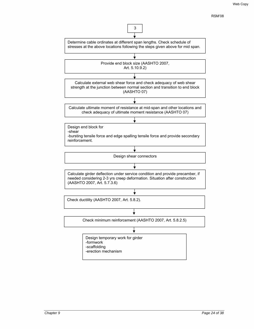
RSM’08
Chapter 9 Page 24 of 38
3
Determine cable ordinates at different span lengths. Check schedule of stresses at the above locations following the steps given above for mid span.
Provide end block size (AASHTO 2007, Art. 5.10.9.2)
Calculate external web shear force and check adequacy of web shear strength at the junction between normal section and transition to end block
(AASHTO 07)
Calculate ultimate moment of resistance at mid-span and other locations and check adequacy of ultimate moment resistance (AASHTO 07)
Design end block for -shear -bursting tensile force and edge spalling tensile force and provide secondary reinforcement.
Design shear connectors
Calculate girder deflection under service condition and provide precamber, if needed considering 2-3 yrs creep deformation. Situation after construction (AASHTO 2007, Art. 5.7.3.6)
Check ductility (AASHTO 2007, Art. 5.8.2).
Check minimum reinforcement (AASHTO 2007, Art. 5.8.2.5)
Design temporary work for girder -formwork -scaffolding -erection mechanism
Web Copy

RSM’ 08
Chapter 9 Page 25 of 38
9.4 CONSTRUCTION AND ERECTION OF PC GIRDER, DECK AND RAILING 9.4.1 General The bridge structures of this Manual will be constructed mainly in the remote rural areas. The country is reverine where early monsoon flood is likely to occur. Thus construction period is short. The construction methodology adopted for the bridge superstructure should keep this into Consideration.
The composite superstructure of the bridge involves 20-40 meters c/c bearing span PC girders. Cast-in-situ RC deck slab is shear-connected with these PC girders. Erection of scaffolding and formwork for these PC girders and RC deck in the alluvial bed of the moving streams has risk of formwork settlement. Thus in-situ construction of the superstructure by erecting scaffolding from the river bed should preferably be avoided.
The following sections give details of the appropriate construction methodology of the components of the superstructure.
9.4.2 Construction / erection methodology of PC girder 9.4.2.1 Construction methodology
The PC girders of this Manual are of post-tensioned type for which basically two methods of construction are available: a) Cast-in-place method The PC girders may be constructed cast-in-situ in the following situations:
• For overpasses where props can be supported over the road/ground level below by diverting traffic.
• For construction of bridge across a river or channel whose bed remains dry during the winter season and the construction may then be done by erecting scaffolding on the dry bed.
• For construction of bridge across a perennially flowing river or channel or for cases where very large height of scaffolding is required, cast-in-situ method of construction by erecting truss support for the girder forms over the adjacent abutment/pier might be used. In that case the construction of the PC girder can be continued during monsoon season also.
The sketch showing typical details of a truss support for PC girder form is shown in Fig. 9.4.1. The trusses shown in Fig. 9.4.1 are used in pair which will be adequately braced together against lateral buckling. This method of construction is suitable up o 30.0 m span length. b) Precast method and erection methodology In precast method, the girders may be constructed at places adjacent to the exact locations of" the girders, immediately below the spans, behind the abutment or in precast yards. After concreting and prestressing of the girders either partially or fully and grouting the stressed cable ducts, these are transported, lifted, shifted and placed in position as applicable.
Web Copy

RSM’ 08
Chapter 9 Page 26 of 38
• Lifting and shifting of girders When the PC girders are concreted adjacent to their actual locations, these may be lifted
b% hydraulic jacks, shifted by sliding and placed in positions by lowering as required. Fig. 9.4(b) shows the typical details of lifting and shifting arrangement of precast girders. • Using Jin Pole system After completing the girder concreting adjacent to the spans immediately below, either at
dry bed level or by erecting low height scaffolding, this may be lifted and shifted by using Jin pole system.
Jin Pole is an improvised indigenous system for lifting of the precast girders. Jin Pole is
actually a steel trestle like arrangement with a central pipe pole. Similar two poles are used to lift the girders by holding them at the two lifting points adjacent to their ends. The stability of the poles is maintained through several guy ropes tied to the anchors at ground level. The pole can be lifted by playing with the guys so that the girders can be shifted or rotated by certain amount. This helps to place the girders in position at the bearing level. Fig. 14.3 shows one typical detail of the Jin-Pole.
• Using launching girder The launching girder is a space truss system to move the girders longitudinally to their
actual positions from their casting yard behind the abutment. Fig. 14.4 shows the typical plan and longitudinal sections of a launching girder. Fig. 14.5 shows the details of the lifting arrangement using the launching girder.
• Using crane
The girders are concreted in the precast yard either away from or nearer to the location of the bridge. These are then transported by trailers and then lifted and placed in position by using cranes.
• Lifting and shifting by Jack
The girders are constructed as precast over abutment or pier cap at the level of the bearing but outside its actual location. A pair of truss may be erected with supports over the abutment/pier cap. Girder forms are placed over it, Girders are then constructed, cured, stressed, grouted, lifted and shifted by jacks, and placed in position.
• Constructed over Barge & then placed in position
For the river bridge, the girders are concreted over the barge and then lifted and shifted in position by using chain pulley.
9.4.3 Deck slab The deck slab may be cast on deck forms supported on PC girders. The form supports for the deck including its cantilever projections may be provided by putting inserts in the PC girders. The inserts are double nuts threaded inside the top flange of the PC girders. Deck forms are supported by the girders through bolts threaded inside these nuts. All temporary holes for inserts shall be grouted by pressure grout using non-shrink admixture.
Web Copy
RSM’ 08
Chapter 9 Page 27 of 38
9.4.4 Rail and rail post The railing system consists of precast rail bars and rail posts as shown on the drawings. The objectives of selecting precast railing system are: • The standard form works can be used repeatedly for making the rails in the precast yards
and repair and replacement of these during service period w i l l be easy • The repeated use of the standard form work will make the construction economical. • Repair and replacement of the precast rail and rail posts will be easier. • Being precast, the members will have better finish and therefore these will be aesthetically
pleasant. • Fabrication, erection and placement of precast rails and rail posts will be easier and
faster. The precast rail posts will be placed inside preformed grooves. The grooves will be cleaned. wetted and dried to saturated surface dry condition. The empty space between the groove and rail post base will be grouted. Precast rail bars will then be fixed with rail posts by bolts as shown on the drawings and thereafter the recess will be grouted for corrosion protection of the nuts and bolts. 9.5 STRESSING AND GROUTING OF PC GIRDER 9.5.1 General The post-tensioning method of prestressing has been used for the PC girder of this Manual. The girders are of 20.80 to 40.80 meter total lengths and will be constructed in the remote areas where skilled supervisors for prestressing works may not be available in all cases. Therefore, the detailed procedures of the storing, handling of the sheath and cables, sheathed cable laying, stressing and grouting are given in the subsequent subsections. Since the anchorages shown on the drawings are based on Freyssinet system, Freyssinet Int'l Organization's Guide for Freyssinet Method has been used for detailing of the prestressing and grouting works. For further details, the original literature may be consulted.
9.5.2 Handling and placing of cables 9.5.2.1 Cable Storing The bright metal sheaths and cables should be stored under cover. 9.5.2.2 Cable placing The cables must be placed in the form according to the plan and profile shown on the drawings and attached sufficiently and strongly to the reinforcing cage in order to avoid any displacement during concreting. 'U' shaped saddles of 8 mm mild steel welded (preferably) or attached to one branch of the stirrup to fix the sheathed cables. The first support should be 30 cm from the anchorage so as to ensure the cable is co-axial with the anchorage and firmly held during concreting. The spacing of the other supports for 1207 cables should be about 1.15 meters.
Web Copy
RSM’ 08
Chapter 9 Page 28 of 38
The sheathed cables may be pulled into a mild steel cage. Initially the cables are suspended temporarily either from the stirrups or from supports on the side form. Their adjustment and final fixing are made after placing the last cable. For the required cable profile, points may be painted on side form. The cable need only be adjusted to this profile. For final adjustment it is the good eye of the site engineer which best avoids the cable wobble and sharp changes of radius which increase the friction losses. After completion of placing but before closing the form (for girders), the engineer must check the following: a) Cable profile The cables must follow a regular profile without wobble. The cable ordinates at the most important sections should be checked. b) Water tightness of the sheath The sheath should be inspected when placed. Damage caused by handling and placing must be repaired with adhesive tape. A second inspection must be made after final adjustment before closing the form. The grout vents must be checked at this time. c) Strength of the supports The cables must be firmly held vertically and horizontally and must remain in position during concrete placement and vibration. Welded cables are the most reliable cable supports. The anchorage must be strongly attached to the form. d) Anchorage zone The sheath connection with an anchorage sleeve must be water tight. The joint between anchorage and form must also be water tight. The extra length of wire for jack attachment must be checked particularly when the cables cannot be moved in their sheaths after concreting or if replacement is impossible. The cable must be straight and coaxial with the anchorage for a distance of about 60 cm. All bursting reinforcement, particularly for anchorages near an edge, must be carefully checked. Never forget that time spent in doing the job well and carefully checking the cables will avoid a much greater loss of time in the following operations.
9.5.2.3 Stressing equipment and handling of HT strand cables a) Stressing Equipment Appropriate multi-strand jacks with pumps from approved sources shall be used. The elongation and jacking force for each cable, the minimum concrete strength before stressing and stressing phases and their sequences are given in the drawings of the PC girders.
Web Copy

RSM’ 08
Chapter 9 Page 29 of 38
b) Pre-start checks
Stressing can begin when the following conditions are met:
• The concrete strength shown on the drawing has been reached.
• The cable ends are accessible.
• All end forms and recess boxes are removed.
• All obstructions must be removed from the jacking area. Space must be left for the jack opening due to the elongation of the cable: about 6 mm per meter of wire cables.
• The female cone of embedded anchorages must be checked the day after concreting and cleaned if necessary.
c) The stressing equipment should be in working order
The following must be checked:
• Jacks, pumps, leads and all accessories delivered to site correspond to the materials ordered.
• The pump is wired for the power supply available on site (220V or 380V-3 Phase). Provide a generator (13 kava) if necessary.
• The electrical leads are of sufficient lengths and amperage for the power supply.
• The hydraulic oil in the pumps is upto level.
• The pressure gauges have been calibrated. The recalibration with a master gauge (sent with the pump) must be carried out regularly, every 200 stressing operations or atleast once a week, as well as at any sign of malfunctioning.
d) Handling of the Jacks on site The jack must be hung from a height sufficient to allow easy vertical and horizontal movement for threading onto the cables to be stressed. A suspension ring is provided on the jack. Because of the ring the body of the jack remains accessible for fixing the wires. Various commercial hoists exist. mounted on wheels, which facilitates moving the jack from one cable to another. If a crane is available on site, it is often used for handling the jack. e) Site record with the Supervising Engineer The schedule with the stressing sequence, the gauge pressure and the elongations should be in the hands of the site supervising engineer. Check that the internal jack friction of 4% is included in the gauge pressure.
9.5.3 Stressing procedure 9.5.3.1 Preparation of the cable and the anchorage The wire surface must be perfectly clean of all substances which could prevent a good anchorage. Traces of mortar must be removed with a steel brush. The internal surface of the female cone must be clean.
Web Copy

RSM’ 08
Chapter 9 Page 30 of 38
9.5.3.2 Placing the male cone Wire crossing in the sheath just behind the anchorage must be avoided when placing the male cone: a) Insert the male cone between the wires or strands so that it is firmly held with each
wire or strand in its groove.
When a central spiral is used, it must be removed from the anchorage zone before driving in the male cone. Pull it to one side and cut as close to the anchorage as possible. The end of the spiral springs back into the sheath and will not jam between the male cone and female cone when blocking. The placing of the male cone is simplified by using a special tool called a star template.
b) Drive the male cone inside the female cone using:
• either a wooden shaft and a small hammer:
• or a steel tube and a sledge hammer for strand cables.
The male cone must project slightly of the outer face of the female cone. When stressing does not take place immediately after placing the male cones, tie the progressing wire with a wire to avoid cuts or damage to clothes.
9.5.3.3 Placing the Jack • Grease very lightly the grooves of the jack for easy automatic dewedging of jacks using
a graphite grease (Belleville Grease wi th 60% graphite) or. if not available, use candle grease or paraphine. For the jacks which use individual grips to anchor the wires or strands, the inside of the barrels must be greased with the same graphite grease.
• Place the jack on the anchorage with each wire or strand in a groove of the jack head. Push the jack home.
• Place the wedges using sharp hammer blows making sure that the wires/strands lie correctly in the grooves of the jack. When the serrations become blocked, soak the wedges in petrol for a few minutes and clean them with a steel brush.
If the serrations become worn, change the wedges. • For jack with individual grips, first attach the wires or strands by threading on the barrels
and then place the wedges and drive them home using a piece of tube supplied with the jack. Check the wedge serrations and clean them as above or change when necessary.
Web Copy

RSM’ 08
Chapter 9 Page 31 of 38
9.5.3.4 Stressing Most construction sites today use motor powered pumps. For the electric pumps used the stressing and return circuits are activated through a distributor. For hand pumps, the leads arc alternately connected to the pump for stressing or dipped into reservoir for the return. The operations must be carried out as follows respecting the order given.
1. Cable Stressing a) Hand Pump without Distributor
Stressing • Hand pump may be allowed up to 25.80 m
long PC girders only • Purge all the leads. • Attach the lead with valve to the tensioning inlet
T of the jack (Fig. A) and to the delivery outlet of the pump.
• Attach one end of the second lead to the blocking chamber B of the jack so as to discharge into the reservoir of the pump (return to the reservoir).
• After stressing to 50 kg/cm2 approx. release the jack suspension. Check the wedges by a tap with the hammer.
• Pump until the cable has reached the required stress and elongation and fill out the stressing book. Never allow the pressure drop when taking readings. Make elongation readings when the pump is stopped.
b) Electric pump with distributor The same operations are carried out using the levers of the distributor, the leads remaining permanently attached. Pumps P2, P4 and P5 carry schematic diagrams of the lever positions for the various operations. 9.5.4 Grouting procedure 9.5.4.1 Why grouting is done? Grouting with cement mortar of the space between the prestressing steel and the sheath which serves as the duct has two major objectives:
a) To protect the steel against corrosion. The life of the structure depends essentially on the quality of this operation
DIACRAM OF THE DISTRIBUTER FOR ELECTRIC PUMPS PI, P«. PS
Web Copy

RSM’ 08
Chapter 9 Page 32 of 38
b) To effect the bond between the prestressing steel and the concrete. The following conditions must be present in order to ensure a good grouting operation: 1. The mortar must completely fill the duct, without air pockets or bleeding pockets. 2. The mortar must not contain any component which could attack the steel. 3. The mortar must have strength of about 250 Kg/cm2 after hardening. Good grouting requires in addition the following:
• The duct must in no way have obstacles to the flow of mortar, and must be as uniform as possible, without sudden changes of cross section;
• The are a of the free space inside the sheath, must be at least equal to the prestressing steel area;
• The grouting equipment must be sufficiently powerful to ensure the passage of the mortar from one end to the other of the duct in spite of the head loss
• The cables must have cut-off s at both ends so that the grout can be kept under pressure until it sets (see § 5.3).
Important note - Before beginning grouting, the sealing of the anchorages must have reached a sufficient strength. 9.5.4.2 Composition of the mortar a) Properties of the mortar In order to correctly fulfill all of the varied requirements of a good grout the mortar must:
• be homogeneous and therefore mixed mechanically;
• have less than 3 % bleeding. It must be sufficiently fluid to allow normal grouting with the available equipment. The consistency of a good grout must be thick or about that of a thick paint and not a liquid. From the preceding the advantages are apparent in using plastifiers. These allow a reduction of the water cement ratio in the mixture and facilitate the maintenance in suspension of the cement particles, improving the workability. The freeze resistance of the mortar is likewise improved by certain additives. Different plastifiers, reatarders and expansive agents are available from different sources. The risk of freezing during setting is eliminated with an expansive agent. Expansion is due to an aluminium powder in the mixture. For cases where the use of this aluminium powder is not recommended, other appropriate type of admixtures from approved source can be used, but the benefit of the expansive agent is lost.
Web Copy

RSM’ 08
Chapter 9 Page 33 of 38
The supplier must give a guarantee that his product does not contain any component likely to cause corrosion of the steel. The cement to be used is Portland cement and it must contain absolutely no calcium chloride. Blast furnace slag cements are not recommended. Salt water (case of maritime works) must not be used for making grout. 9.5.4.3 Grout Mixes The following composition is recommended: Sieved Portland cement 50 .................................................................................... kg Water …………………………………………………………………………17 liters Plastifier - Intraplast Z or equivalent ………………………………………..1 kg Plastifier - Intraplast Z (for temperatures between +2° C and + 5° C) 1.5 kg When using a sand grout (21 kg sand for 50 kg of cement) the quantity of water will be 19 liters. The sand must be fine and clean of the Fontainebleau type (0 to 0.5 mm). Hot cements must not be used since the grout obtained is difficult to pump. The proportion of water given above may be increased (10 % maximum) if the grouting pressure becomes too high (greater than 15 kg/cm2). 9.5.4.4 Mixing of the Mortar The mortar is prepared in a mixing drum first by introducing the water, then the cement, the plastifier and finally the sand (when used). The mixing must be started up just before adding the cement. Generally electric paddle mixers are used. Mixing must not be interrupted while adding the cement and must be continued for 5 minutes after adding all components. The mixing drum must be placed at a height such that the mortar can flow directly into a second tank, the feed tank, placed beneath the mixing drum. Before flowing into the feed tank the mortar must pass through a 2 mm mesh screen so as to eliminate impurities and lumps. If it is not to be used immediately, the mortar in the feed tank must be stirred from time to time to avoid segregation. 9.5.4.5 Grouting Details To ensure a good connection between pump and duct, a plastic inlet must be provided from the anchorage at the time of sealing. Before grouting the sealing must be checked for sufficient strength, in general reached after one, or two days (four days in winter). When grouting, the plastic tube is connected to the pump leads using an “express” coupler. Before grouting a test with compressed air must be made to ensure that the duct is clean and free.
Web Copy
RSM’ 08
Chapter 9 Page 34 of 38
For an oiled cable, or in hot weather condition, or when a bare concrete duct has been used (without sheath), the cable should be washed by pumping water under pressure through the duct and then blowing out with compressed air before grouting. Grouting must be performed, avoiding any sudden pressure fluctuations. Pressure must be held below a limiting value depending upon the sheath strength and strength of the surrounding concrete (for ducts near outer surfaces). In practice the pressure should not exceed 20 kg/cm2. The site personnel who connect the leads and activate the pump must wear protective goggles to avoid accidents such as high pressure mortar getting into the eyes. When the grout consistency at outlet end is comparable with that at the inlet, the outlet plastic tube is bent back and tied in the same way as a bal1oon valve. If the pressure falls, it is raised again to about 5 K/cm2 and maintained at this level. The plastic rube at the grouting end is then bent back and tied in the same way. The pressure in the pump is then released through the by pass valve and the leads taken off. The plastic tubes must not be cut off for 24 hours in summer and 48 hours in winter, when a retarder is used, which is generally the case. 9.5.4.6 Vents When the cable drape exceeds 60 cm, for example in continuous structures, each high point must be vented to release trapped air and water. Long cables must be vented at about every 60m. Under certain conditions drain tubes should be provided at low points of long cables and for cables with a very high drape (consult the Works Department of STUP). Steel tube vents brazed to a piece of sheet metal bent to a half cylinder can be attached to the sheath by adhesive tape or tie wire after sealing with a mastic. Plastic vents of the same type are also available. Certain sheath manufacturers supply short lengths of sheath with vents which may be screwed onto the normal sheath. It is advisable to extend these vents at the high points by 50 cm plastic tubes thus providing voids into which air and bleed water can accumulate. The vents are closed by bending back and tying the plastic tube. When grouting draped cables with several high points, the first vent is closed, when the grout consistency is comparable. to the inlet grout, and pumping is continued until a good mortar flows from the next vent, which is closed in turn, and so on until the opposite end of the cable is reached. If the cable is very long and the pressure high, grouting can be continued by one of the vents, after closing off the original inlet point.
Web Copy

RSM’ 08
Chapter 9 Page 35 of 38
9.5.6 Grouting of Vertical and Inclined Cables Grouting of vertical and inclined cables must be carried out from the bottom. In this way air pockets are avoided. For very high vertical cables the pumps should be placed at a certain height and connection should be made to the low point (anchorage or bottom vent) by means of a pipe. The pump head is thus used for grouting. For vertical “U” shaped cables less than 5m high, grouting from the top using one of the upper ends of the U is possible. When the grout flows from the other end of the “U”, the grouting direction is reversed and pumping is continued until no traces of air bubbles can be seen at the outlet. For higher “U”s grouting is carried out from a vent at the low point.
Web Copy

RSM’ 08
Chapter 9 Page 36 of 38
Appendix – 9.3.3.3-1
Web Copy

RSM’ 08
Chapter 9 Page 37 of 38
Web Copy

RSM’ 08
Chapter 9 Page 38 of 38
Web Copy

RSM’08
Chapter 10 Page 1 of 4
CHAPTER 10
SUBSTRUCTURE OF BRIDGES 10.1 DESIGN 10.1.1 General Substructure of a bridge is the portion between the bridge bearings and the pile cap which transmits loads from the superstructure to the foundation. Generally abutment-wing wall, pier, etc. are considered as substructure of a bridge.
10.1.2 Allowable Stresses of Materials
For substructure the material strengths have been used as follows:
Concrete: 28 days cylinder strength in accordance with BDS EN 197-1 f’c = 20 MPa.
Steel: Conforming to BDS 1313: 1991Grade 275 deformed bar, minimum fy = 275 MPa. 10.1.3 Longitudinal Load Longitudinal loads on the abutment-wing wall are due to the following lateral load items:
• Active pressure due to saturated backfill. • Active pressure due to live load surcharge equivalent to 0.61 meter earth load. • Hydrostatic pressure due to 0.61 meter head difference below high flood level (HFL). • Due to wind. • Due to seismic loading. • Due to stream current force arisen after the passive earth is removed from 3 sides of the
abutment-wing wall. • From superstructure due to thermal expansion and contraction, shrinkage, creep and
braking of vehicles transferred through the bridge bearings.
Most likely all these loads will not occur simultaneously. The load combinations have been used in accordance with the ASSHTO 2007 (ref.: Chapter 6).
10.1.4 Design Philosophy: The design is made in accordance with AASHTO2007 LRFD method. The design steps are shown in the Design Flow Chart (Article 10.1.5).
Web Copy
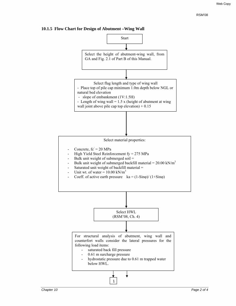
RSM’08
Chapter 10 Page 2 of 4
10.1.5 Flow Chart for Design of Abutment –Wing Wall
Start
Select the height of abutment-wing wall, from GA and Fig. 2.1 of Part B of this Manual.
Select flag length and type of wing wall - Place top of pile cap minimum 1.0m depth below NGL or natural bed elevation - slope of embankment (1V:1.5H) - Length of wing wall = 1.5 x (height of abutment at wing wall joint above pile cap top elevation) + 0.15
Select material properties:
- Concrete, fc/ = 20 MPa - High Yield Steel Reinforcement fy = 275 MPa - Bulk unit weight of submerged soil = - Bulk unit weight of submerged backfill material = 20.00 kN/m3 - Saturated unit weight of backfill material = - Unit wt. of water = 10.00 kN/m3 - Coeff. of active earth pressure ka = (1-Sinφ)/ (1+Sinφ)
Select HWL (RSM’08, Ch. 4)
For structural analysis of abutment, wing wall and counterfort walls consider the lateral pressures for the following load items:
- saturated back fill pressure - 0.61 m surcharge pressure - hydrostatic pressure due to 0.61 m trapped water
below HWL.
1
Web Copy

RSM’08
Chapter 10 Page 3 of 4
No
Assume member thickness, dia. and spacing of reinforcement steel for the components in each region.
Calculate vertical and horizontal moments in abutment wall considering 3-edge fixed support condition for the above lateral pressures from STAAD/Pro model.
Calculate min. flexural strength = 1.2 Mcr where Mcr = fr.lg/yt. (Ref. AASHTO 2007 Art. 5.7.3.6.2) - ve Design Moment, -MLFD = Max. of (MLFD & 1.2 Mcr) +ve Design Moment, +MLFD = Min. of (1.33MLFD & 1.2 Mcr)
Calculate lever arm factor a = As.fy/ (0.85 fc/ .b) Calculate flexural strength of each component φMn = 0.9 As.fy(d-a/2)
Calculate: - ratio of reinf. P - ratio of reinf. pb
which produces balanced strain
Calculate deflection for Flag wall portion of wing wall under service load and check
Is ФMn > MLFD?
Yes
Shear Design is O.KIs 0.85 Vc >
YesNo
No
Calculate shear strength provided by concrete Vc = 0.166 (sqrt. fc/)bw.d in SI
Flexural Design is O.KIs p<0.75 pb
Yes
Calculate the B.M and shear force for the wing wall using the factored load as per AASHTO’07 (ref. Ch. 6), and STAAD/Pro program.
1
Web Copy

RSM’08
Chapter 10 Page 4 of 4
For combination of the elastic seismic force effects o abutment, the provisions of AASHTO 2007, Article 3.10.8 shall be applied (refer to Plate 10-1). 10.2 CONSTRUCTION METHODOLOGY Since the substructure for the RSM’08 bridges involve abutment only, these are located mostly on bank of the channel; and so their construction will be straightforward. The structural excavation and backfill should be done taking care that construction can be done on dry and properly formed bed, and that after construction the original bank shape is restored. Conventional water tight formwork and scaffolding should be adequate. In case of prestressed concrete girder, back wall should be constructed after completing stressing of the HT cables and grouting of the ducts. This will facilitate placing the jacks and the pumps.
Web Copy
RSM’08
Chapter 11 Page 1 of 12
CHAPTER 11
CAST-IN-PLACE RC PILE FOUNDATION AND PILE CAP 11.1 BORED CAST-IN-PLACE RC PILES
11.1.1 General
Article 11.1.6 and 11.2.3 show the flow chart for designing the cast-in-place piles and the abutment-wing walls respectively. This flow chart shows simplified procedure to calculate pile bending moments for laterally loaded piles, which will be easier for field engineers in the remote site offices of LGED to follow. For estimating the pile length both in the cohesionless and cohesive soil, the Flow Chart 2.2 in Part – B, Volume I & II may be referred.
Deep pile foundations have been provided below 4.00 to 8.00 meter high abutment-wing walls. Cast-in-place bored piles have been provided as long length laterally loaded piles. Precast piles have not been provided as the laterally loaded precast pile may require expensive moment resisting splicing, and which can’t be mobilized in the country easily. Further reasons are as follows: • Cast-in-place bored piles can be installed up to any reasonable length required by design
with the rig available in the region. • Cast-in-place bored piles can be installed in almost any type of soil by using bentonite slurry
using temporary casing at the top only, provided the soil contains more than 10 per cent fines.
• In the limited cases of purely granular soil, permanent casing might be required for which special design will be needed.
• The pile diameter has been restricted to a single size of 600 mm to facilitate easy installation with the available rigs.
11.1.2 Design Philosophy
The piles have been designed as laterally loaded piles. For 4.00 to 8.00 meter high abutments, the lateral load due to backfill is considerable. The group of vertical piles has been provided to cater for the axial and lateral loads. Raker bored piles have been avoided as construction of the same is difficult with the technology available in the country.
Scour below RC pile cap is likely to occur in case of extreme flood unless the bottom level of pile cap is placed at maximum scour level. In that case deep excavation below ground water table (GWT) might require lowering of the GWT either by using turbine pump or well point dewatering system for construction of the pile cap in dry bed. This is an expensive method of construction- as an alternative the bottom elevation of pile cap has been provided at a higher elevation by providing a minimum of about 1.0 meter earth cushion above top of the pile cap. Further, it is to be ensured that the maximum scour depth below pile cap bottom does not exceed 1.00 meter for the standard structures of this Manual.
Web Copy
RSM’08
Chapter 11 Page 2 of 12
11.1.2.1 Service Load on Pile
This has been calculated in accordance with the AASHTO load groups given in AASHTO 2007, considering the entire abutment-wing wall and the pile cap as one unit. The flow chart given in Article 11.1.6, gives the design steps for the stability analysis and for determining the service and factored vertical and horizontal loads on each pile row.
The service load on pile is calculated using the method given in ‘Chapter 4 Calculating the resistance of piles to compressive loads” of Tomlinson’s “Pile Foundation Design and construction Practice, 4th edition” and AASHTO 2007. The spreadsheet example given in Part – C Design examples give the detailed procedures with example.
There is a controversy as regards effect of penetration depth on the pile capacity. Vesic showed that for cohesionless soil the increase of base resistance with increasing depth was not linear as might be implied from the expression:
Qp = Nq σ′v0 Ab + ½ Ks σ′v0 As
where,
Qp = ultimate resistance of pile, kN
σ′v0 = effective overburden pressure at pile base level, kN/m2
Nq = the bearing capacity factor
Ab = nominal plan are of the base of pile, m2
As = surface area of the pile shaft, m2
Ks = coefficient of horizontal soil stress
Vesic stated, “For practical design purposes it has been assumed that the increase is linear for pile penetrations of between 10 and 20 diameters, and that below these depths the unit base resistance has been assumed to be at a constant value.” Tomlinson is of opinion that ‘This simple design approach was adequate for ordinary foundation work where the penetration depths of closed ended piles were not usually much greater than 10 to 20 diameters. He further stated, “the use of piled foundations for offshore petroleum production platforms has necessitated driving hollow cylindrical piles with open ends to very great depths below the sea bed to obtain resistance to in skin friction to uplift loading. The assumption for a constant unit base resistance below a penetration depth of 10 to 20 pile diameters has been shown to be over-conservative. It can be demonstrated theoretical analysis, and proved by field experience, that the base resistance does not remain constant or reduce with depth. However, the rate of increase does increase with depth in a soil deposit of uniform density.’
For the purposes of this Manual, conservative value of angle of internal friction, Ө, ultimate cohesion, c, bearing capacity factors, Nq and Nc have been considered. The pile loading test on the service pile for 1.5 times the service load will be the basis of selection of the pile load. Pile settlement at ultimate load shall be considered not exceeding 5% pile diameter in compliance with the AASHTO’07 provisions, and at service load shall not exceed 10 mm.
Web Copy
RSM’08
Chapter 11 Page 3 of 12
11.1.2.2 Structural design of pile
The structural analysis and design have been made based on the method of Reese and Matlock method. The factored vertical and horizontal loads have been calculated for all applicable AASHTO load groups. The critical load is normally the combination which gives the minimum vertical and maximum horizontal load per pile. While calculating the horizontal load per pile the RC pile cap has been considered as a rigid plate distributing total longitudinal load at foundation level equally amongst all piles.
The lateral load capacity of each pile has been calculated based on the lateral subgrade modulus of soil. The pile head has been embedded about 75 mm in the pile cap, and in addition all the pile reinforcement has been projected by the anchorage bond length of 40xbar diameter into the pile cap. Accordingly, the pile head has been considered as fixed-headed. The design bending moment for the fixed-headed laterally loaded pile has been calculated based on the method of Reese and Matlock (Ref: M.J. Tomlinson, Pile Foundation Design and Construction Practice, 4th edition). The pile reinforcement has been calculated based on the software “PCA COL” by Portland Cement Association.
11.1. 2.3 Pile reinforcement
In the pile, the primary reinforcement (upper cage) has been provided as designed by the above method. A minimum of 1.0% reinforcement has been provided in the lower cage of pile reinforcement in compliance with the AASHTO ‘07. The spacing of spiral reinforcement has been provided as 75 mm c/c (max.) as per AASHTO 2007.
11.1.3 Material and work specification
11.1.3.1 Concrete
The concrete for cast-in-place pile shall be manufactured as per specification using Class 25 concrete (minimum cylinder compressive strength at 28 days, f’c = 25 N/mm2). The concrete shall be placed by using a tremie pipe which shall be sufficiently long to reach the bottom level of pile and gradually withdrawn as the placing of concrete proceeds.
11.1.3.2 Casing Pipe
Temporary steel casing pipe of required diameter shall be used at least for the upper 3m from ground level during drilling to stabilize the hole. Permanent steel casing pipe if provided in the schedule of items of work, shall be of the required diameter, length and thickness and shall be lowered up to the designed depth immediately after the drilling of hole is completed. At the option of the contractor the permanent casing pipe, may be lowered simultaneously with the progress of drilling and the use of temporary casing pipe may be eliminated. Casing pipes may be transported to site at suitable lengths of pieces and shall be welded as per specification to fabricate the design length. The permanent steel casing pipes shall be free from rust, pits or any other deformity and the inside of the pipe shall be free from paint, grease or any other deleterious substance that may affect the concrete.
Web Copy

RSM’08
Chapter 11 Page 4 of 12
11.1.3.3 Reinforcement
The reinforcement for cast-in-place concrete piles shall meet the requirement of the specification for reinforcing steel for structures. All turns of spirals shall be tack welded at 3 places and lapping of vertical reinforcement shall be allowed if shown on the drawings.
11.1.3.4 Welding
11.1.3.5 Electrodes
All arc welding electrodes shall conform to AWS standards and the electrodes shall be rods of size and classification number as recommended by their manufacturers.
11.1.3.6 Quality
Welding of reinforcing bars shall be performed by skilled and experienced welder and the connections shall be made in accordance with AWS. 11.1.4 Method of pile construction
11.1.4.1 Preparation
Before starting drilling operation the contractor shall establish levels, grades and alignment of all piles with reference to bench marks (BM) previously established at site. The Contractor shall have all casing and ready for reinforcing bars fabricated as per design and ready for lowering after the completion of drilling. All necessary equipment such as pump, welding set etc. and materials for concrete work including tremie pipe shall be made available before the start of drilling operation.
11.1.4.2 Drilling
The drilling method and equipment to be used shall be approved by the Engineer. The Contractor shall prepare suitable cofferdam/artificial island/staging or any other approved means, if required, for the drilling operation and concreting the piles and piers in water. Bentonite slurry shall be used to stabilize the hole.
Drilling mud shall comprise bentonite of liquid limit about 350, density 1.03 – 1.10, API sand content 0 – 2% by volume, pH between 8 & 11, API Marsh Funnel viscosity 30 – 40 sec. Specification for mud circulation tremie concreting are give in the LGED Standard Specifications and should be followed.
11.1.4.3 Pile cluster
Where there are more than (4) four piles in a cluster, the centre pile shall be installed first. All piles in a cluster shall be of the same depth.
Web Copy

RSM’08
Chapter 11 Page 5 of 12
11.1.4.4 Tolerance for drilling holes
Bore holes shall be accurately drilled in the locations shown in the contract drawing. All piles shall be drilled with a lateral tolerance of not more than 75 mm from the point specified. Piles that deviate more than 75 mm in lateral location or piles whose slope deviates from the vertical by more than 2 (two) percent shall be rejected. Additional piles shall then be furnished and installed by the contractor in such locations as the Engineer may direct. AH costs of such additional piles required to suit changed pile locations shall be borne by the contractor.
11.1.4.5 Obstruction during drilling
When obstructions make it extremely difficult to drill certain boreholes in the locations shown on the drawings and to the proper bearing strata, the contractor shall adopt all necessary measures to install piles as required including jetting, as approved by the Engineer. If the contractor is unable to complete properly any pile restoring to such technically sound methods, the Engineer may order additional hole(s) drilled at another location(s) at the Contractor's expense.
11.1.4.6 Depth of hole
The depth of borehole shall be checked by the Engineer-in-charge by lowering suitable drop to determine the length of pile. Immediately after approval of the bore hole, the steel casing pipe shall be provided up to the design depth, if shown in the Schedule of Items of Works, and then the reinforcement cage shall be lowered.
11.1.4.7 Measurement and payment
The cast-in-place bored pile of the required size shall be paid as per length of pile cast measured in linear m from the bottom of the pile to the cut-off level and paid at the contract unit price shown in the Schedule of Items of Works and shall be the full compensation for providing all equipment and incidentals necessary to complete the work, except reinforcing steel which shall be paid separately. Permanent steel casing pipe, cofferdam/cross dam/ring bundh/ artificial island/staging in water shall be paid separately if shown in the drawing and Schedule of Items of Works.
No payments shall be made for temporary casing pipe or bentonite slurry used for stabilizing the drilled hole. 11.1.5 Load test on piles
i) This item shall consist of the application of a test load on a service pile selected by the Engineer-in-charge to determine the potential bearing capacity and adequacy of the pile by observation of its settlement behavior under test load.
ii) The Contractor shall submit to the Engineer-in-charge for approval of all plans and procedures for the load tests including platform, weights or jacks, gauges, set-up for surveying and loading and unloading sequence. The Contractor shall furnish dependable gauges and drives (sensitivity 0.025 mm) as approved by the Engineer-in-charge for measuring the settlement and shall furnish the Engineer-in-charge with a recent
Web Copy

RSM’08
Chapter 11 Page 6 of 12
verification of the gauge calibration by a reliable agency. The contractor shall also furnish the Engineer-in-charge with adequate facilities for making load and settlement readings 24 hours per day except such engineering instruments and apparatus as are included in an engineer's regular equipment, e.g., surveying equipment, etc..
iii) The test load shall be concentrically applied by such a method that the test load acting on the pile at any time may be definitely determined and controlled.
iv) The load shall be applied to the pile as near to the ground surface as possible. The test loading will not be considered satisfactory if the pile fails internally during the test loading due to improper installation or procedure by the Contractor.
v) The head of the pile shall be cut off, levelled and capped with a steel plate in such a manner as to produce a horizontal plane of bearing surface. The total test load shall be twice the anticipated working load on the pile and shall be applied in increments amounting to 25, 50,75, 100, 125, 150, 175 and 200 per cents of the anticipated working load. The first application of the load shall be made after the curing period is over and concrete achieves the required strength but not earlier than 72 hours after the driving of the pile to be tested. Increment of load shall be applied not earlier than 2 hours after all measurable settlement (0.25 mm or less in 20 minutes) caused by the previous loading. A careful reading of settlement shall be made immediately before and after the application of such increment of loads and at the intermediate interval of 20 minutes apart. On completion of full test loading, the load shall remain on the pile 24 hours or more if the necessity for that is indicated by the rate of the settlement of the pile. The settlement reading shall be taken during and at the end of the period.
vi) The pile shall be unloaded in stipulated decrements as directed by the Engineer-in-charge. During unloading of the pile, the rebound shall be measured when the load remaining on the pile amounts to 75, 25,
10 and 0 per cent of the full test load at not more than half hour intervals with measurements of the rebound being immediately before and after each decrement. The final rebound shall be recorded 24 hours after the entire test load has been removed.
vii) A check for the accuracy of the settlement shall be made from a fixed reference point to determine adequacy of the whole settlement attachment. Any pile or stake serving or fixed reference shall be driven at a distance of 2.44 m or more from the nearest point of the test pile. If it is necessary to remove and reapply the load, it shall be reapplied gradually and not suddenly.
Web Copy

RSM’08
Chapter 11 Page 7 of 12
11.1.6 Flow Chart for structural design of Cast-in-situ Bored Pile
Is the sub-soil granular?
Is the soil stiff clay?
B
Start
Calculate the service vertical and horizontal loads for the applicable AASHTO load groups
Select design load group which gives minimum vertical load Nu and maximum longitudinal load at pile head Hu
Calculate maximum scour depth Dmax (see Ch. 4 of this manual)
Select the sub-soil type below pile cap and around the maximum scour depth
Select relative density Dr from SPT Ncorr and then read coefficient of modular variation nh from Fig 11.1
Select pile dia. And calculate stiffness factor T= (EI/nh) 1/5, where E= Modulus of elasticity of pile concrete kN/m2 I= Second moment of area of pile concrete, m4
Select nh: - for normally consolidated
clay nh= 700 kN/m3 - for organic soil, nh= 150
kN/m3
Select lateral subgrade modulus k from Table
Calculate stiffness factor R = (EI/K) 1/4
A
Web Copy
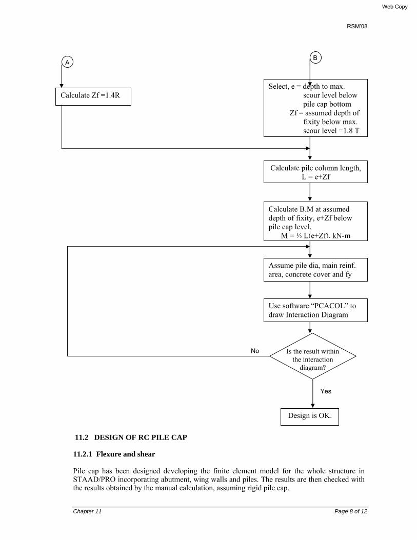
RSM’08
Chapter 11 Page 8 of 12
11.2 DESIGN OF RC PILE CAP
11.2.1 Flexure and shear
Pile cap has been designed developing the finite element model for the whole structure in STAAD/PRO incorporating abutment, wing walls and piles. The results are then checked with the results obtained by the manual calculation, assuming rigid pile cap.
B
Calculate Zf =1.4R
A
Select, e = depth to max. scour level below pile cap bottom
Zf = assumed depth of fixity below max. scour level =1.8 T
Calculate pile column length, L = e+Zf
Calculate B.M at assumed depth of fixity, e+Zf below pile cap level,
M = ½ L(e+Zf), kN-m
Assume pile dia, main reinf. area, concrete cover and fy
Use software “PCACOL” to draw Interaction Diagram
Design is OK.
Yes
No Is the result within the interaction
diagram?
Web Copy

RSM’08
Chapter 11 Page 9 of 12
Maximum factored pile loads are then used for pile cap design following AASHTO 2007 method.
While designing pile cap reinforcement along traffic direction, maximum positive moment at toe side has been calculated by taking moment about the river side face of the abutment wall, considering a suitable design strip as described in flow chart for design of pile cap (Art. 11.3).
The design loads have been considered as the maximum reaction of piles and minimum vertical downward factored load due to self weight of pile cap and soil fill as per AASHTO'07.
While designing pile cap reinforcement along transverse direction, the strip has been considered as the entire area of the pile cap behind the earth face of the abutment. The maximum vertical upward reaction of piles on the pile cap, and balanced uniformly distributed downward loads/reactions has been considered for equilibrium of the strip and design purposes. At the base of wing wall a concentrated moment due to backfill and surcharge pressure has been calculated in accordance with Reynold's Hand book (12th ed.), Table 53 and Theory of Plates and Shells, Table 44 have been used.
Punching shear is checked for a corner pile as by examination it is found that corner piles are critical for punching shear. For conformance to the AASHTO requirement, PRmax should be greater than Vc,
where PRmax = maximum pile reaction in LFD Vc = φ x 0.332 √fc' b0 d Ø = reduction factor = 0.85 b0 = effective perimeter for punching shear d = effective depth of pile cap
11.2.2 Reinforcement
At any section of pile cap where tension reinforcement is required by analysis, the reinforcement provided should be adequate to develop a moment equal to at least 1.2 times the cracking moment calculated on the basis of the modulus of rupture as per AASHTO'07, Art. 5.4.2.6 and Art. 5.7.3.6.2.
Accordingly, the Design Moment should be greater or equal to 1.2 Mcr where, Mcr = fr Ig/y
in which, fr = Modulus of Rupture = 0.63 cf ' , f’c is in MPa [AASHTO ’07, Art. 5.4.2.6]
gI = 12
3hb×
c = Pile cap thickness/2
11.2.3 Construction methodology of pile cap Pile cap must be constructed as show on drawing and under dry condition.
Web Copy
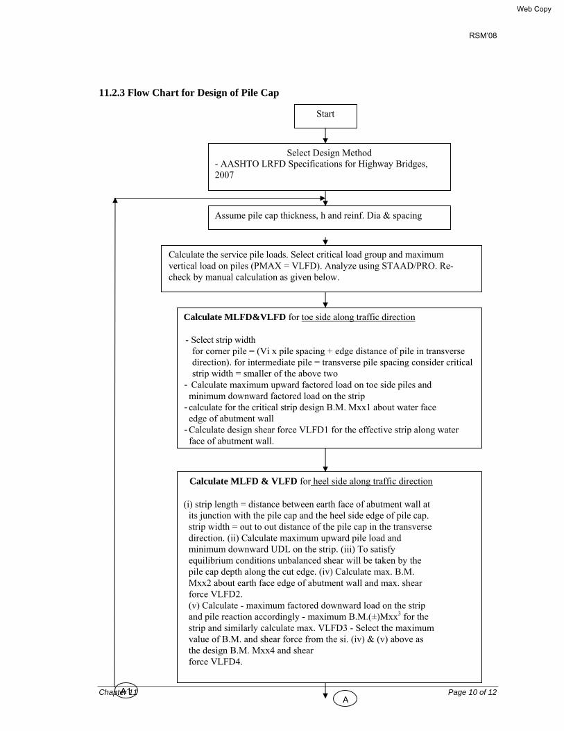
RSM’08
Chapter 11 Page 10 of 12
11.2.3 Flow Chart for Design of Pile Cap
A
Start
Select Design Method - AASHTO LRFD Specifications for Highway Bridges, 2007
Calculate MLFD&VLFD for toe side along traffic direction
- Select strip width for corner pile = (Vi x pile spacing + edge distance of pile in transverse direction). for intermediate pile = transverse pile spacing consider critical strip width = smaller of the above two
- Calculate maximum upward factored load on toe side piles and minimum downward factored load on the strip
- calculate for the critical strip design B.M. Mxx1 about water face edge of abutment wall
- Calculate design shear force VLFD1 for the effective strip along water face of abutment wall.
Assume pile cap thickness, h and reinf. Dia & spacing
Calculate the service pile loads. Select critical load group and maximum vertical load on piles (PMAX = VLFD). Analyze using STAAD/PRO. Re-check by manual calculation as given below.
Calculate MLFD & VLFD for heel side along traffic direction
(i) strip length = distance between earth face of abutment wall at its junction with the pile cap and the heel side edge of pile cap. strip width = out to out distance of the pile cap in the transverse direction. (ii) Calculate maximum upward pile load and minimum downward UDL on the strip. (iii) To satisfy equilibrium conditions unbalanced shear will be taken by the pile cap depth along the cut edge. (iv) Calculate max. B.M. Mxx2 about earth face edge of abutment wall and max. shear force VLFD2. (v) Calculate - maximum factored downward load on the strip and pile reaction accordingly - maximum B.M.(±)Mxx3 for the strip and similarly calculate max. VLFD3 - Select the maximum value of B.M. and shear force from the si. (iv) & (v) above as the design B.M. Mxx4 and shear force VLFD4.
A1 A
Web Copy
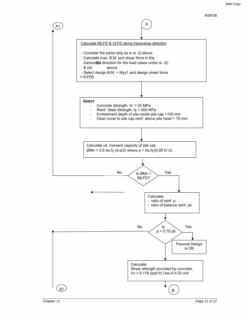
RSM’08
Chapter 11 Page 11 of 12
Yes
Calculate MLFD & VLFD along transverse direction
- Consider the same strip as in si. (i) above - Calculate max. B.M. and shear force in the
transverse direction for the load cases under si. (ii) & (iii)
B1 above
- Select design B.M. = Myy1 and design shear force = VLFD5.
Select - Concrete Strength, fc’ = 25 MPa - Reinf. Steel Strength, fy = 400 MPa - Embedment depth of pile inside pile cap =100 mm - Clear cover to pile cap reinf. above pile head = 75 mm
Calculate ult. moment capacity of pile cap ØMn = 0.9 As.fy (d-a/2) where a = As.fy/(0.85 fc'.b)
Calculate - ratio of reinf. p - ratio of balance reinf, pb
Is p < 0.75 pb
Flexural Design is OK
YesNo
No
Calculate Shear strength provided by concrete, Vc = 0.116 (sqrt fc’) bw.d in SI unit
Is ØMn > MLFD?
A1 A
B1 B
Web Copy

RSM’08
Chapter 11 Page 12 of 12
Is 0.85 Vc > VLFD?
Is ØVc(punching)>Pmax
Shear Design is OK.
Calculate punching shear strength of concrete at d/2 from face of support considering two way punching action for the corner pile having maximum reaction
Punching Shear Strength is OK.
Provide min. reinf. where tension reinf. is required by analysis so that ØMn≥1.2Mcr, where Mcr = fr. Ig/c
Check and adjust minimum reinf. for shrinkage and temperature stresses.
Design is Ok.
B1
B
No Yes
No Yes
Yes No
Web Copy

RSM’08
Chapter 12 Page 1 of 13
CHAPTER 12
REINFORCED ELASTOMERIC BEARING & EXPANSION JOINT
12.1 GENERAL This chapter contains requirement for the design, selection and construction/erection methodology of structural bearings and deck joints. AASHTO 2007, Section 14 (SI) has been taken as the main basis of design for the reinforced elastomeric bearings. Deck joints are the improvised design based on the conventional practice of the RHD & LGED for small and medium length bridges, span up to about 40.00 m. 12.2 DEFINITIONS Bearing
A structural device that transmits loads while facilitating translation and rotation Closed Joint
A deck joint designed to prevent the passage of debris through the joint and to safeguard pedestrian and cyclic traffic Compressed seal
A preformed elastomeric device that is precomprssed in the gap of a joint with expected total range of movement less than 50 mm Construction joint
A temporary joint used to permit sequential construction Damper
A device that transfers and reduces forces between superstructure elements and/or superstructure and substructure elements, while permitting thermal movements. The device provides damping by dissipating energy under seismic, braking, or other dynamic loads Deck joint
A structural discontinuity between two elements, at least one of which is a deck element. It is designed to permit relative translation and/or rotation of abutting structural elements. Fixed bearing
A bearing that prevents differential longitudinal translation of abutting structural elements. It may or may not provide for differential lateral translation or rotation.
Web Copy

RSM’08
Chapter 12 Page 2 of 13
Joint A structural discontinuity between two elements. The structural members used to frame or form the discontinuity. Joint seal A poured or preformed elastomeric device to prevent moisture and debris from the penetrating joints. Longitudinal joint A joint parallel to the span direction of a structure provided t separate a deck or superstructure into two independent structural systems. Metal rocker or roller bearing A bearing that carries vertical load bb direct contact between two metal surfaces and that accommodates movement by rocking or rolling of one surface with respect to the other. Movable bearing A bearing that facilitates differential horizontal translation of abutting structural elements in a longitudinal and/or lateral direction. It may or may not provide for rotation. Multirotational bearing A bearing consisting of a rotational element of the pot type, disc type, or spherical type when used as a fixed bearing and that may, in addition, have sliding surfaces to accommodate translation when used as an expansion bearing. Translation may be constrained to a specified direction by guide bars. Neutral point The point about which all of the cyclic volumetric changes of a structure take place. Open joint A joint designed to permit the passage of water and debris through the joint. Plain elastomeric pad (PEP) A pad made exclusively of elastomer, which provides limited translation and rotation. Polytetrafluoroethylene (PTFE) Also known as teflon. Pot bearing A bearing that carries vertical load by compression of an elastomeric disc confined in a steel cylinder and that accommodates rotation by deformation of the disc. Poured seal A seal made from a material that remains flexible (asphaltic, polymeric, or other), which is poured into the gap of a joint and is expected to adhere to the sides of the gap. Typically used only when expected total range of movement is less than 40 mm.
Web Copy
RSM’08
Chapter 12 Page 3 of 13
PTFE sliding bearing
A bearing that carries vertical load through contact stresses between a PTFE sheet r woven fabric and its mating surface, and that it permits movements by sliding of the PTFE over the mating surface. Relief joint
A deck joint, usually transverse, that is designed to minimize either unintended composite action or the effect of differential horizontal movement between a deck and its supporting structural system. Restrainers
A system of high strength cables or rods that transfers forces between superstructure elements and/or superstructure and substructure elements under seismic or other dynamic loads after an initial slack is taken up, while permitting thermal movements. Sealed joint
A joint provided with a joint sea. Shock transmission unit
A device that provides a temporary rigid link between superstructure elements and/or superstructure and substructure elements under seismic, braking, or other dynamic loads, while permitting thermal movements. Sliding bearing
A bearing that accommodates movement by translation of one surface relative to the other. Steel-reinforced elastomeric bearing
A bearing made from alternate laminates of steel and elastomer bonded together during vulcanization. Vertical loads are carried by compression of the elastomer. Movements parallel to the reinforcing layers and rotations are accommodated by deformation of the elastomer. Strip seal
A sealed joint with an extruded elastomeric seal retained by edge beams that are anchored to the structural elements (deck, abutments, etc). Typically used for expected total movement ranges from 40 to 100 mm, although single seals capable of spanning a 125 mm gap are also available. Translation
Horizontal movement of the bridge in the longitudinal or transverse direction. Waterproofed joints
Open or closed joints that have been provided with some form of trough below the joint to contain and conduct deck discharge away from the structure.
Web Copy

RSM’08
Chapter 12 Page 4 of 13
12.3 STEEL-REINFORCED ELASTOMERIC BEARINGS (AASHTO 2007, Article 14.7.5)
12.3.1 General
It may be designed using either by using Method A or Method B. The stress limits associated with Method A usually resulting a bearing with a lower capacity than a bearing designed using Method B. This increased capacity resulting from the use of Method B requires additional testing and quality control. Method A is used for this manual purposes. Tapered elastomeric layers shall not be used. Tapered layers cause larger shear strains and bearings made with them fail prematurely due to delaminating or rupture of reinforcement. All internal layers of elastomer shall be of the same thickness because the strength and stiffness of the bearing in resisting compressive load are controlled by the thickest layer. Holes are strongly discouraged in steel-reinforced bearings. However, if holes are used, their effect should be accounted for when calculating the shape factor because they reduce the loaded area and increase the area free to bulge. The top and bottom cover layers shall be no thicker than 70% of the internal layers (ref: AASHTO’07, Article 14.7.5.1). 12.3.2 Shape factor of bearing, Si
It’s an important parameter for the reinforced elastomeric bearing. If L is the length of a rectangular elastomeric bearing (parallel t the longitudinal axis in mm, W is the width of a bearing in the transverse direction in mm, and hri is the of ith layer in elastomeric bearing in mm, then Si = [{(LW)/ {2hri (L + W)}] 12.3.3 Material Properties (AASHTO’07, Article 14.7.5.2)
The shear modulus of elastomer at 23° C shall be used as the basis of design. If the material is specified by its shear modulus that value shall be used in design and other properties. If the material is specified by its hardness, the shear modulus shall be taken as the value from the range for that hardness given in the Table 12.3-1 (reproduced from AASHTO’07, Table 14.7.6.2-1). Materials with a shear modulus greater than 1.3 MPa are prohibited because they generally have a smaller elongation at break and greater stiffness and greater creep than their softer counterparts. This inferior performance is generally due to the larger amounts of filler present. Their fatigue behavior does not differ in a clearly distinguishable way from that of softer materials. Shear modulus, G, is the most important material property for design, and it is, therefore, the primary means of specifying the elastomer. Hardness has been widely used in the past, and is still permitted for AASHTO’07, Method A design, because the test for it is quick and simple. However the results obtained from it are variable and correlate only loosely with shear modulus.
Web Copy
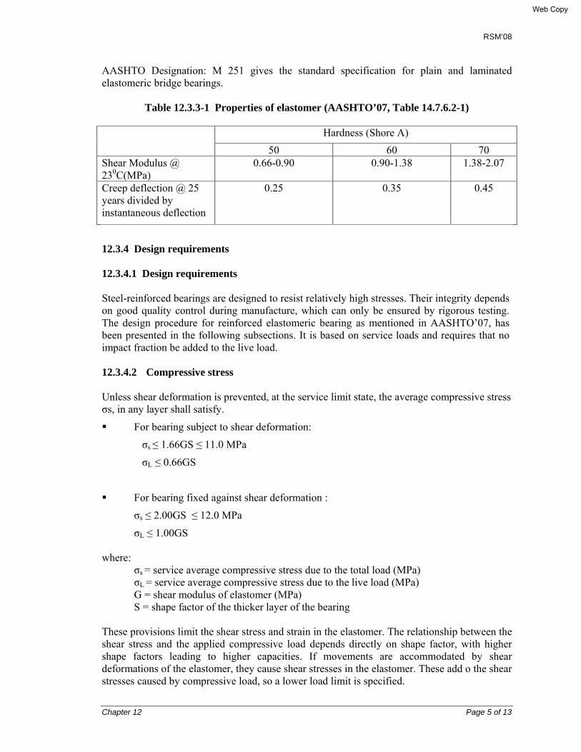
RSM’08
Chapter 12 Page 5 of 13
AASHTO Designation: M 251 gives the standard specification for plain and laminated elastomeric bridge bearings.
Table 12.3.3-1 Properties of elastomer (AASHTO’07, Table 14.7.6.2-1)
Hardness (Shore A)
50 60 70 Shear Modulus @ 230C(MPa)
0.66-0.90 0.90-1.38 1.38-2.07
Creep deflection @ 25 years divided by instantaneous deflection
0.25 0.35 0.45
12.3.4 Design requirements 12.3.4.1 Design requirements Steel-reinforced bearings are designed to resist relatively high stresses. Their integrity depends on good quality control during manufacture, which can only be ensured by rigorous testing. The design procedure for reinforced elastomeric bearing as mentioned in AASHTO’07, has been presented in the following subsections. It is based on service loads and requires that no impact fraction be added to the live load. 12.3.4.2 Compressive stress Unless shear deformation is prevented, at the service limit state, the average compressive stress σs, in any layer shall satisfy.
For bearing subject to shear deformation:
σs ≤ 1.66GS ≤ 11.0 MPa
σL ≤ 0.66GS
For bearing fixed against shear deformation :
σs ≤ 2.00GS ≤ 12.0 MPa
σL ≤ 1.00GS where: σs = service average compressive stress due to the total load (MPa) σL = service average compressive stress due to the live load (MPa)
G = shear modulus of elastomer (MPa) S = shape factor of the thicker layer of the bearing
These provisions limit the shear stress and strain in the elastomer. The relationship between the shear stress and the applied compressive load depends directly on shape factor, with higher shape factors leading to higher capacities. If movements are accommodated by shear deformations of the elastomer, they cause shear stresses in the elastomer. These add o the shear stresses caused by compressive load, so a lower load limit is specified.
Web Copy
RSM’08
Chapter 12 Page 6 of 13
The compressive stress limits, in terms of GS, were derived from static and fatigue tests (Roeder and Stanton, 1986; Roeder et al, 1990). The absolute limits of 11 and 12 MPa came from the static tests. Delamination is a service limit state, but it may lead to more serious structural problems. The specified stress limits provide a safety factor of approximately 1.5 against initial delamination. 12.3.4.3 Compressive deflection Deflections of elastomeric bearings due to dead load and to instantaneous live load alone shall be considered separately. Instantaneous live load deflection shall be taken as:
δL = ΣεLi hri (12.3.4.3-1)
where, εLi = instantaneous live load compressive strain in ith elastomer layer of a
laminated bearing hri = thickness of ith elastomeric layer in a laminated bearing (mm).
Initial dead load deflection shall be taken as:
∆d = Σεdi hri (12.3.4.3-2)
where, εdi = initial dead load compressive strain in ith elastomer layer of a laminated
bearing hri = thickness of ith elastomeric layer in a laminated bearing (mm). Long term dead load deflection, including the effects of creep, shall be taken as:
δlt = δd + acr δd (12.3.4.3-3)
where, acr = creep deflection divided by initial dead load deflection (dim.) Limiting instantaneous live load deflections is important to ensure that deck joints and seals are not damaged. Furthermore, bearings that are too flexile in compression could cause small step in the road surface at a deck joint when traffic passes over it, giving rise to impact loading. A maximum relative live load deflection across a joint of 3 mm is suggested. Plate 14.3-1, reproduced from AASHTO’07, Fig. C14.7.6.3.3-1, provides design aids for determining the strain in an elastomer layer for steel reinforced bearings based upon durometer hardness and shape factor.
Web Copy

RSM’08
Chapter 12 Page 7 of 13
Plate 14.3-1
12.3.4.4 Shear deformation The maximum horizontal displacement of the bridge superstructure, ∆0, shall be taken as 65% of the design thermal movement range, ∆T, combined with the movement caused by creep, shrinkage, post tensioning. The maximum shear deformation of the bearing, ∆s, shall be taken as the horizontal bridge movement, modified to account for the pier flexibility and construction procedures. The maximum shear deformation of the bearing, at the service limit state, ∆s, shall be taken as ∆0, modified to account for the substructure stiffness and construction procedures. The bearing shall be designed to satisfy:
hrt ≥ 2∆s (12.3.4.4-1)
where,
hrt = total elastomer thickness of the bearing (m ∆s = maximum total shear deformation of the elastomer at the service limit state.
Web Copy
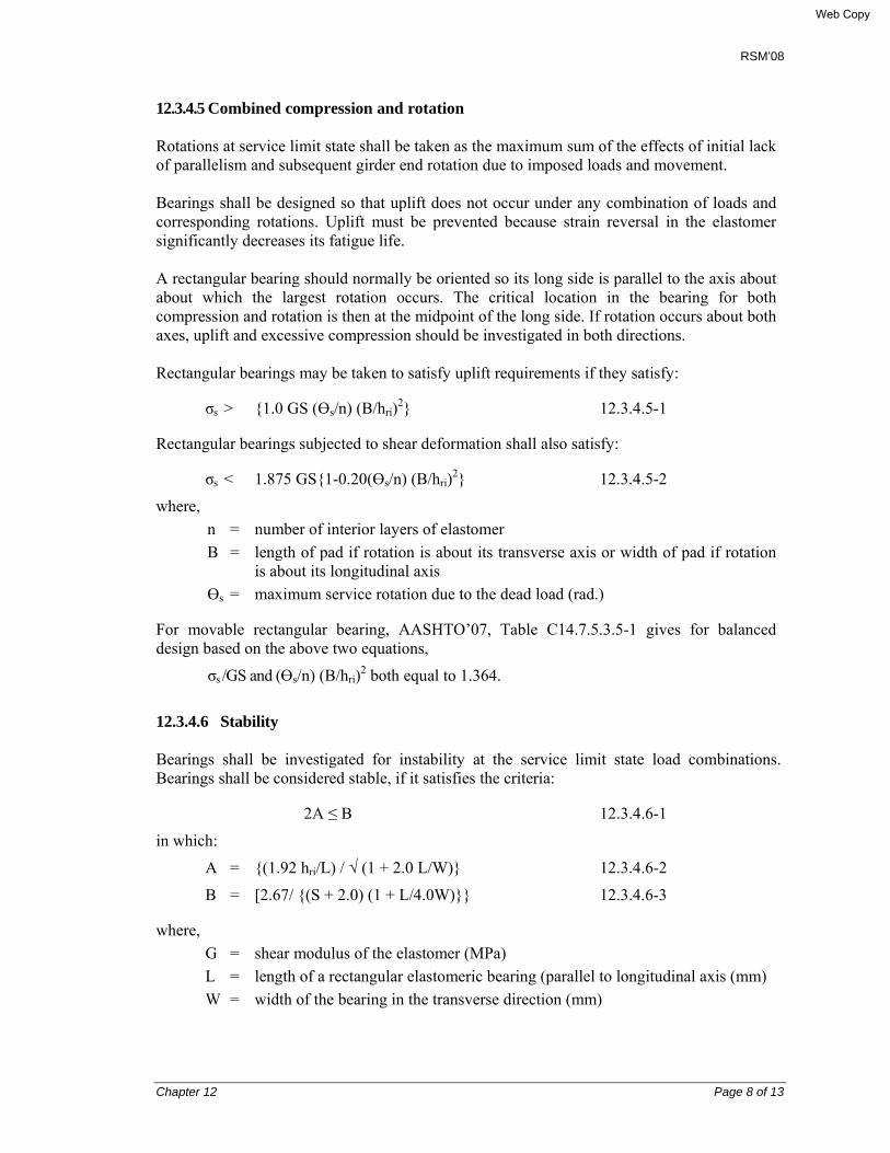
RSM’08
Chapter 12 Page 8 of 13
12.3.4.5 Combined compression and rotation Rotations at service limit state shall be taken as the maximum sum of the effects of initial lack of parallelism and subsequent girder end rotation due to imposed loads and movement. Bearings shall be designed so that uplift does not occur under any combination of loads and corresponding rotations. Uplift must be prevented because strain reversal in the elastomer significantly decreases its fatigue life. A rectangular bearing should normally be oriented so its long side is parallel to the axis about about which the largest rotation occurs. The critical location in the bearing for both compression and rotation is then at the midpoint of the long side. If rotation occurs about both axes, uplift and excessive compression should be investigated in both directions. Rectangular bearings may be taken to satisfy uplift requirements if they satisfy:
σs > {1.0 GS (Өs/n) (B/hri)2} 12.3.4.5-1
Rectangular bearings subjected to shear deformation shall also satisfy:
σs < 1.875 GS{1-0.20(Өs/n) (B/hri)2} 12.3.4.5-2
where, n = number of interior layers of elastomer B = length of pad if rotation is about its transverse axis or width of pad if rotation
is about its longitudinal axis Өs = maximum service rotation due to the dead load (rad.)
For movable rectangular bearing, AASHTO’07, Table C14.7.5.3.5-1 gives for balanced design based on the above two equations,
σs /GS and (Өs/n) (B/hri)2 both equal to 1.364.
12.3.4.6 Stability
Bearings shall be investigated for instability at the service limit state load combinations. Bearings shall be considered stable, if it satisfies the criteria:
2A ≤ B 12.3.4.6-1
in which:
A = {(1.92 hri/L) / √ (1 + 2.0 L/W)} 12.3.4.6-2
B = [2.67/ {(S + 2.0) (1 + L/4.0W)}} 12.3.4.6-3
where, G = shear modulus of the elastomer (MPa) L = length of a rectangular elastomeric bearing (parallel to longitudinal axis (mm) W = width of the bearing in the transverse direction (mm)
Web Copy

RSM’08
Chapter 12 Page 9 of 13
For rectangular bearings not satisfying Equation 12.3.4.6-1, the stress due to the total load shall satisfy Equation 12.3.4.5-4.
• If the bridge deck is free to translate horizontally: σs ≤ GS/(A – B) 12.3.4.6-4
12.3.4.7 Reinforcement The thickness of the steel reinforcement, hs, shall satisfy:
• At the service limit state: • hs ≥ (3 hmax σs/Fy) 14.3.4.7-1 • At the fatigue limit state: • hs ≥ (2 hmax σL/ ∆FTH) 14.3.4.7-2
where,
∆FTH = constant amplitude fatigue threshold for Category A as specified in Article AASHTO’07, Article 6.6 (MPa)
hmax = thickness of thickest elastomer layer in elastomeric bearing (mm)
σL = service average compressive stress due to live load (MPa)
σs = service average compressive stress due to total load (MPa)
fy = yield strength of steel reinforcement (MPa) 12.4 INSTALLATION
12.4.1 Elastomeric bearing
12.4.1.1 General Bearings should be furnished with dimensions, material properties, elastomer grade and type of laminates required by the drawings. These should conform to minimum 50 ± 5 Shore A hardness in accordance with ASTM Designation: D 2240. 12.4.1.2 Steel plate The finish of surfaces of steel plate laminate in contact with the elastomeric pad shall be smoother than 1.5µm. Steel laminates used for reinforcement shall be made from rolled mild steel conforming to ASTM A36, A570 or equivalent unless otherwise specified by the Engineer-in-charge. The laminates shall have a minimum thickness as shown on the drawings. Holes in plates for manufacturing purposes will not be permitted unless they have been accounted for in the design and shown on the drawing. 12.4.1.3 Bond The vulcanized bond between elastomer and reinforcement shall have a minimum peel strength of 5.2 kN/lm (30 lb/in.). Steel laminated bearings shall develop a minimum peel
Web Copy

RSM’08
Chapter 12 Page 10 of 13
strength of 6.9 kN/lm (40 lb/in.). Peel strength test shall be performed in accordance with ASTM D 429 Method B. 12.4.1.4 Manufacture Bearing with steel laminates shall be cast as a unit in a mould and shall be bonded and vulcanized under heat and pressure. The mould finish shall conform to standard shop practice. The internal steel laminates shall be sand blasted and cleaned of all surface coatings, rust, mill scale, and dirt before bonding, and shall be free from sharp edges and burrs. Bearings that are designed to act as a single unit with a given shape factor must be manufactured as a single unit 12.4.1.5 FABRICATION TOLERANCES Plain pads and laminated bearings shall be built to the specified dimension within the following tolerances: Overall Height
- Design Thickness 32mm or (11/4 in.) or less - 0 +3 mm
- Design Thickness over 32mm - 0, + 6 mm
- Overall Horizontal Dimension 914mm (36 in.) or less - 0, + 6 mm
- Thickness of Individual Layers of Elastomer (Laminated Bearings only) At any point within the bearings - Parallelism with opposite face Top and bottom sides
- Edge Cover Embedded Laminates 0, + 6mm
- ± 20% of design value but not more than ± 3mm 0.005 radian 0.02 radian 0, + 3mm
12.4.1.6 Marking and certifying The manufacturer shall certify that each bearing satisfies the requirements of the drawings and these specifications, and shall supply a certified copy of material test results. Each reinforced bearing shall be marked with indelible ink or flexible paint the bearing identification number, elastomer type and grade number. The marking shall be on the face that is visible after erection of the bridge. 12.4.1.7 Testing i) General Materials for elastomeric bearings and the finished bearings themselves shall be subjected
to the tests described in this section. Material tests shall be in accordance with the appropriate section 18.3 of AASHTO LRFD Bridge Construction specification.
ii) Ambient temperature tests on the elastomer The elastomer used shall atleast satisfy the limits prescribed in the appropriate section
Web Copy
RSM’08
Chapter 12 Page 11 of 13
18.3, Art. 14.7.4.2 AASHTO 2004 for durometer hardness, tensile strength, ultimate elongation, heat resistance, compression set, and ozone resistance. The bond to the reinforcement, if any, shall also satisfy the requirement of Article 13.1.4 above. The shear modulus of the material shall be tested at 23°c (73°F) using the apparatus and procedure described in annex A of ASTM D4014. It shall be either equal to or greater than the value shown on the drawing.
iii) Visual inspection of the finished bearing Every finished bearing shall be inspected for compliance with dimensional tolerances and
for overall quality of manufacture. In steel reinforced bearings, the edges of the steel shall be protected everywhere from corrosion.
iv) Short duration compression tests on bearings The bearing shall be loaded in compression to 1.5 times the maximum design load. The
load shall be held constant for 5 minutes, removed, and re-applied for another 5 minutes. The bearing shall be examined visually while under the second loading. If the bulging pattern suggests laminate parallelism or a layer thickness that is outside the specified tolerances, or poor laminate bond the bearing shall be rejected. If there are three or more separate surface cracks that are greater than 0.2mm (0.08 in.) wide and 0.2mm (0.08 in.) deep, the bearing shall be rejected.
v) Long duration compression tests on bearings The bearing shall be loaded in compression to 1.5 times its maximum design load for a
minimum period of 15 hours. If, during the test, the load falls below 1.3 times the maximum design load, the test duration shall be increased by the period of time for which the load is below this limit. The bearing shall be examined visually at the end of the test while it is still under load. If the bulging pattern suggests laminate parallelism or a layer thickness that is outside the specified tolerances, or poor laminate bond the bearing shall be rejected. If there are three or more separate surface cracks that are greater than 0.2mm (0.08 in.) wide and 0.2mm (0.08 in.) deep, the bearing shall be rejected.
vi) Shear modulus tests on bearing material The shear modulus of the material in the finished bearing shall be evaluated by testing a
specimen cut from it using the procedure given in annex A of ASTM D4014. If the test is conducted on finished bearings, the material shear modulus shall be computed from the measured shear stiffness of the bearing, taking due account of the influence on shear stiffness of bearing geometry and compressive load.
12.4.2 Installation of bearing Bearings shall be placed on surfaces that are plane to within 1.5 mm (1/16 in.) and horizontal to within 0.01 radian. Any lack of parallelism between the top of the bearing and the underside of the girder that exceeds 0.01 radian shall be corrected by grouting or as otherwise directed by the Engineer-in-charge.
Web Copy
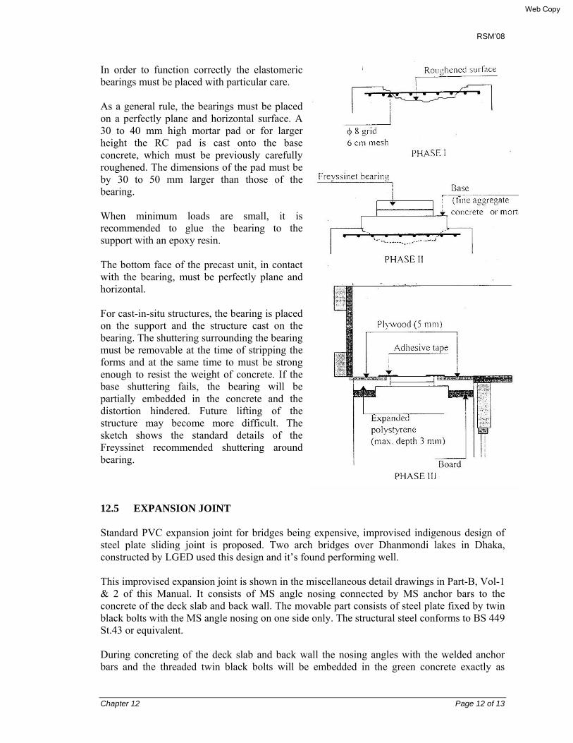
RSM’08
Chapter 12 Page 12 of 13
In order to function correctly the elastomeric bearings must be placed with particular care. As a general rule, the bearings must be placed on a perfectly plane and horizontal surface. A 30 to 40 mm high mortar pad or for larger height the RC pad is cast onto the base concrete, which must be previously carefully roughened. The dimensions of the pad must be by 30 to 50 mm larger than those of the bearing. When minimum loads are small, it is recommended to glue the bearing to the support with an epoxy resin. The bottom face of the precast unit, in contact with the bearing, must be perfectly plane and horizontal. For cast-in-situ structures, the bearing is placed on the support and the structure cast on the bearing. The shuttering surrounding the bearing must be removable at the time of stripping the forms and at the same time to must be strong enough to resist the weight of concrete. If the base shuttering fails, the bearing will be partially embedded in the concrete and the distortion hindered. Future lifting of the structure may become more difficult. The sketch shows the standard details of the Freyssinet recommended shuttering around bearing. 12.5 EXPANSION JOINT Standard PVC expansion joint for bridges being expensive, improvised indigenous design of steel plate sliding joint is proposed. Two arch bridges over Dhanmondi lakes in Dhaka, constructed by LGED used this design and it’s found performing well. This improvised expansion joint is shown in the miscellaneous detail drawings in Part-B, Vol-1 & 2 of this Manual. It consists of MS angle nosing connected by MS anchor bars to the concrete of the deck slab and back wall. The movable part consists of steel plate fixed by twin black bolts with the MS angle nosing on one side only. The structural steel conforms to BS 449 St.43 or equivalent. During concreting of the deck slab and back wall the nosing angles with the welded anchor bars and the threaded twin black bolts will be embedded in the green concrete exactly as
Web Copy

RSM’08
Chapter 12 Page 13 of 13
shown on the drawing. A steel template will be used to maintain alignment and position of the black bolts. The steel movable plate will be fixed with the bolts by nuts. One R20 MS bar will then be welded at the edge of the other side nosing angle. The gap between the plate and the welded bar will then be filled by bituminous filler material. The joint may be installed during 2nd stage, after concreting of deck and back wall with nosing.
Web Copy
RSM’08
Chapter 13 Page 1 of 5
CHAPTER 13
RC BOX CULVERT
13.1 DESIGN 13.1.1 General The provisions herein shall apply to the hydraulic and structural design of cast-in-place and precast reinforced (RC) box culverts. Box culverts are generally provided, either where the channel isn’t defined, or where distributed overland discharge is necessary to allow flow from one side of the road embankment to the other side. These may be single cell or multi-cell structures. Also, these may be buried structures with height of fill above the top slab or its top slab may be placed at road formation level. The length of the box culvert is usually measured perpendicular to the traffic direction. Two types of box culverts are provided. In one type, the box culvert length is provided shorter than the embankment toe lines, having transition structures with flared angles not larger than 450; or of full length between embankment toe lines, plus provision of return type head walls at both the upstream (U/S) and downstream (D/S) ends.
13.1.2 Hydraulic design 13.1.2.1 Design discharge, HWL and scour depth At the start the Hydrologist will decide from reconnaissance survey, whether the box culvert is at all required, and if required, at which location it’s required. Thereafter he will assess its command area, design discharge and the corresponding HWL. Chapter 4.0 gives the detailed procedure about it, including the method of estimating the probable maximum scour depth.
13.1.3 Hydraulics of flow through a culvert The culvert flow may be open channel flow or conduit flow. In the case of open channel flow, the flow through the culvert is given by: Q = CBD (2g∆h)1/2 ∆h = {(Ke/2g) (Vs2 - Vc2) + (Ko/2g) (Vs2 - Vc2)} where, Vs = velocity through structure at both U/S & D/S
Vc = velocity through channel at both U/S & D/S Ke = inlet loss = 0.20 for 300 to 450 wing wall & 0.30 for 900 wing wall Ko = outlet loss = 0.30 for 300 to 450 wing wall & 0.75 for 900 wing wall.
Web Copy
RSM’08
Chapter 13 Page 2 of 5
In the case of conduit flow, the flow through the culvert is given by:
Q = CA (2g∆h)1/2 ∆h = {(Vs2/2g (Ko + Ke + 2Ln2 g/R2/3)} where, the conservative values of the entry and exit loss may be taken as
Ke = inlet loss = 0.50
Ko = outlet loss = 1.00.
The commonly used values for the Manning’s roughness coefficient ‘n’ for concrete pipes are 0.14.
13.1.4 Waterway opening For a culvert flowing full, a suitable width for the rectangular section of a box culvert may be provided. For a trapezoidal channel, its maxima – minima limit may be the bank to bank width, or even slightly less than the bed width of the channel. In case of artificial channel e.g., excavated drainage/irrigation channel, up to 70% fluming/constriction may be allowed for design purposes; and under such conditions, the velocity through the structure should be increased by about 1.43 x velocity in the channel. It may be noted that Leliavosky while designing the irrigation channels of Nile valley in Egypt, provided about 70% constriction of channel. But this requires considering the loss of hydraulic gradient in the channel. For a culvert to be constructed on an undefined channel and flowing partially full, the head difference (afflux) shall be the guiding factor in determination of the width of box opening. In such cases, the head loss in general, should not exceed 150 mm. For culvert flowing full, the head loss through it shall be limited to 100 mm for determining the opening size of the box or pipe.
13.1.5 Loads and distribution (AASHTO 2007, Article 12.11.2) This Article is applicable for distribution of wheel loads and concentrated loads for culverts with less than 600 mm fill only. Refer to Chapter 6 of this Part – A of this RSM’08, for the AASHTO 2007 loads and load combinations.
13.1.6 Equivalent strip widths for box culverts (AASHTO 2007, Article 4.6.2.10) For the designed RSM’08 box culverts traffic travels primarily parallel to the span, and provision for designing the same is included here only. Box culverts are normally analyzed as two-dimensional frames. Equivalent strip widths are used to simplify the analysis of the three-dimensional response to live loads. The distribution widths are based on distribution of shear forces. Distribution widths for
Web Copy

RSM’08
Chapter 13 Page 3 of 5
positive and negative moments are wider; however, using the narrower width in combination with a single lane multiple presence factors provides designs adequate for multiple loaded lanes for all force effects. For such case, the axle load shall be distributed to the top slab for determining moment, thrust, and shear as follows: Traffic parallel to the span: Espan = LT + LLDF(H) where,
Espan = equivalent distribution length parallel to span (mm) LT = length of tire contact area parallel to span, as specified in AASHTO 2007,
Article 3.6.1.2.5 (mm). (ref: Article 6.2.2.5, Part-A of this Manual). LLDF = factor for distribution of live load with depth of fill (limit 1.15 – 1.00). = 1.00 for no fill condition H = depth of fill from top of pavement (mm)
Restricting the live load distribution for the bottom slab to the same width used for the top slab provide designs suitable for multiple loaded lanes, even though analysis is only competed for a single loaded lane. Research into live load distribution of box culverts (MacGrath et al, 2004) has shown that design for a single loaded lane with a multiple presence factor of 1.2 on the live load and using the live load distribution widths as noted above, will provide adequate design loading for multiple loaded lanes with multiple presence factors of 1.0 or less when the traffic direction is parallel to the span (ref: AASHTO 2007, Article C12.11.2.1).
13.1.7 Distribution reinforcement in box culvert AASHTO’07, Article 12.11.2.1 specifies, ‘Requirement for bottom distribution reinforcement in top slabs of such culvert shall be in AASHTO’07, Article 9.7.3.2. Accordingly, mild steel reinforcement for primary reinforcement parallel to traffic shall be: 1750/√S ≤ 50% where,
S = effective span length (clear with of the box culvert cell (mm)
The dynamic load effect for culvert with no fill shall be the same as IM = 33%. Edge beams shall be provided as follows: At ends of culvert runs where wheel loads travel within 600 mm from the end of culvert.
13.1.8 Modifications of earth load for soil structure interaction The detailed assessment procedure for box culvert with fill material above it i.e. for buried culverts the method given in the AASHTO’07, Section 12.11, will be followed.
Web Copy
RSM’08
Chapter 13 Page 4 of 5
13.1.9 Analysis and design The analysis is done developing a model in STAAD/Pro, using the multiple loaded trucks applicable for the double lanes. . The structural design followed the guideline and procedure given in AASHTO’07, Article 5.14.5 (Copy is furnished as Annex 13.1.9-1). Cutoff shall be provided at both upstream and downstream end to reduce scour and to minimize exit gradient. 13.2 CONSTRUCTION 13.2.1 General requirement The construction must be done dry condition. Generally the bearing capacity requirement for the box culvert is low. For the RSM’08 box structures, it’s not exceeding 80 kN/m2. In most of the structures the bed may remain dry during the dry season. Construction during wet seasons and below water may require to install appropriate dewatering system. Construction of cast-in-place RC cutoff at US and D/S ends of box section is the critical item. The structural excavation should be done carefully causing minimum disturbances to the surrounding soil. Its backfill should be done with selected granular material placed in layers and compacted to at least Standard Proctor 95%. Drawing shows 150 mm sand cushion below 75 mm CC bed for the RSM’08 box culverts, as a leveling course. This should be done properly.
13.2.2 Dewatering system Where ground water table is above the excavation level and surface water dewatering may affect the construction, it should be lowered by installing adequate dewatering system. This may be done by installing shallow tube wells at least one at each corner of the excavation yards for the small size structures. 13.2.3 Soil improvement below foundation If the compressible soil e.g., peat exists for a shallow depth below the box section, this may be replaced by well-graded granular material. If the compressible soil exists for a larger depth, replacement of which isn’t practical, then sand drains with pre-loading may be another option. Alternatively, other innovative cost-effective methods may also be explored. For example, in case of loose granular soil at shallow depth vibration by installing concrete vibrators may also serve the purpose.
Web Copy

RSM’08
Chapter 13 Page 5 of 5
Annex 13.1.9-1
Web Copy

RSM’08
Chapter 14 Page 1 of 35
CHAPTER 14
SLOPE PROTECTION WORKS
14.1 PURPOSE The purpose of the slope protection works is to stabilize the slopes of road embankment in general, and around the abutment-wing walls, and approaches of the bridge/culverts of RSM’08 in particular.
14.2 STATE-OF-THE-ART PRACTICE OF SLOPE PROTECTION WORKS IN BANGLADESH
For river training works and for guide bundhs of important river bridges e.g., Jamuna Multipurpose Bridge project, mathematical/physical model study is done to understand the movement of the river and to assess the scour depth. A few examples of state-of-the-art practice of slope protection works in the river bridges of Bangladesh are discussed first. In the Hazi Shariatullah Bridge across River Arial Khan at the 9th km of Mawa-Bhanga section in the South-West zone of Bangladesh, the slopes of the guide bundhs are protected with CC blocks over geotextile filter mats. In the Dharala Bridge, located over the river Dharala near Kurigram district town at 3rd km of Kurigram-Nageshwari-Bhurugamari Road, guide bank has been provided to restrict the river width and to prevent the overflow of water. Its waterside slope has been stabilized with CC blocks in two layers (first (top) layer 450mm x 450mm x 300mm and 2nd layer 380mm x 380mm x 300mm) underlain by a layer of 200mm thick shingles and pea gravels (600mm-40mm and 30mm-10mm). Geo-textile mat is placed between the layer of shingles - pea gravel layers and 100mm thick sand layer over compacted earth. Before placing the revetment, the slope of the guide bank at riverside was developed at 1(V): 2(H), removing all bank irregularities. Class 15 concrete (the cylinder compressive strength 15MPa at 28days according ASTM C39) has been used for making blocks. Beyond toe line, 12.0 m - 28.5 m wide apron consisting of layers of graded stone having depth of 2m has been provided. In Meghna and Meghna Gumti Bridge revetment works consisted of geo-textile bags filled with foam concrete, capping concrete and boulder gabions in front of the revetments (Fig. 14.1). In Bhairab bridge (Bangladesh-UK Friendship Bridge) located across the Meghna River, the river training works have been constructed both along the Bhairab and Ashuganj side banks to prevent possible erosion of both the new bridge and the existing railway bridge. The overall geometry of the river training works was based on both physical and mathematical modeling. The revetment was placed over the developed slope 1(V): 3.5(H). At the toe of revetment a falling apron was constructed on the river bed; its width varying from 15.00 m to 24.00 m and its average thickness is 1.70 m. Below EL 0.0 mPWD, revetment profile was developed by
Web Copy
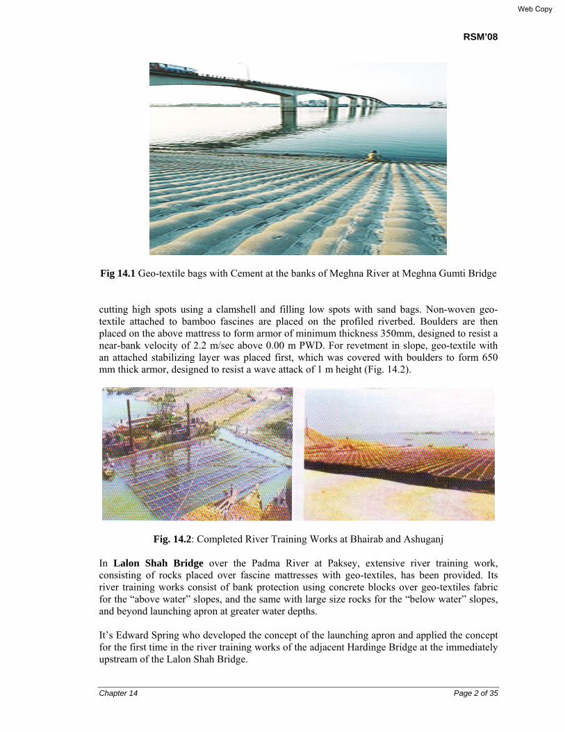
RSM’08
Chapter 14 Page 2 of 35
Fig 14.1 Geo-textile bags with Cement at the banks of Meghna River at Meghna Gumti Bridge cutting high spots using a clamshell and filling low spots with sand bags. Non-woven geo-textile attached to bamboo fascines are placed on the profiled riverbed. Boulders are then placed on the above mattress to form armor of minimum thickness 350mm, designed to resist a near-bank velocity of 2.2 m/sec above 0.00 m PWD. For revetment in slope, geo-textile with an attached stabilizing layer was placed first, which was covered with boulders to form 650 mm thick armor, designed to resist a wave attack of 1 m height (Fig. 14.2).
Fig. 14.2: Completed River Training Works at Bhairab and Ashuganj In Lalon Shah Bridge over the Padma River at Paksey, extensive river training work, consisting of rocks placed over fascine mattresses with geo-textiles, has been provided. Its river training works consist of bank protection using concrete blocks over geo-textiles fabric for the “above water” slopes, and the same with large size rocks for the “below water” slopes, and beyond launching apron at greater water depths. It’s Edward Spring who developed the concept of the launching apron and applied the concept for the first time in the river training works of the adjacent Hardinge Bridge at the immediately upstream of the Lalon Shah Bridge.
Web Copy

RSM’08
Chapter 14 Page 3 of 35
In Jamuna Multipurpose Bridge (4.80 km long), the guide bundhs have been designed considering extreme scour (concave bend scour). The design of bundhs comprises geotextile fascine mattresses overlaying dredged soil slopes. These are covered by rocks, overlain with open asphalt surfacing. 1.5 million tons of rock, from Bangladesh, India, Bhutan and Indonesia has been used to provide the coverage for the guide bundh slopes. To counter the considerable scour effects of the river, the protection works on the guide bunds extend to depths of 15.00 to 18.00 meters below datum, where a falling apron has been provided. The additional rocks dumped in the falling apron have been designed to cover the slopes in case of extreme scour, which may go down to 30 meter below datum. The above examples give an indication how massive the slope protection works are required for the large size river bridges of the country. Compared to those, RSM’08 structures are located over much smaller channels. Considering the general hydrological conditions and hydraulics of these channels, for RSM08 structures, 9 types of slope protection works are provided. 14.3 SLOPE STABILITY
14.3.1 Considering soil mechanics principles
Gravitational and seepage forces tend to cause instability in all kinds of slopes e.g., natural slopes, slopes formed by excavation, and the slopes of embankment. First slope stability analysis should be done to develop stable slopes.
14.3.1.1 Granular soil
Purely granular soil is infrequent unless it’s dredge-filled. In the deltaic country of Bangladesh, most natural soils contain some cohesion.
For predominantly granular soil the factor of safety against slope failure shall be,
F = tanФ/tanβ (14.3.1-1)
where, Ф = angle of shearing resistance β = slope angle with horizontal at toe
For limiting equilibrium (F = 1), tanβ = tanФ, i.e., β = Ф. The principle of slope stability for such soil is explained by an example. If the embankment slope is filled with granular material containing Ф = 300, then Eqn 14.3.1-1 gives for slope 1(V) : 2(H) safety factor F = 1.15 only.
The Equation further shows that theoretically for pure granular soil, the weight of the material doesn’t affect the slope stability; the safe angle for the slope is the same whether the soil is dry or submerged, and the embankment can be of any height.
For a granular soil, effect of seepage forces for a rapid drawdown condition, if any develops needs to be considered. In that case, analysis assuming a potential failure plane, parallel to the slope surface at a depth z, gives
Web Copy

RSM’08
Chapter 14 Page 4 of 35
F = [{(1 – u/γz)/Cos2β}(tanФ/tanβ)] where, u = pore water pressure at depth z, and γ = the average unit weight of the whole slice.
14.3.1.2 Predominantly cohesive soil
In predominantly cohesive soil, the probable modes of failure can be innumerable; but its predominant mode is by formation of rotational slip surface. In it the shape of the failure surface in section may be a circular arc or a non-circular curve. In general, circular slips are associated with homogeneous, isotropic soil conditions and non-circular slips with non-homogeneous conditions. Translational and compound slips occur where the form of the failure surface is influenced by the presence of an adjacent stratum of significantly different strength, most of the failure surface being likely to pass through the stratum of lower shear strength.
The form of the surface would also be influenced by the presence of discontinuities such as fissures and pre-existing slips. Translational slips tend to occur where the adjacent stratum is at a relatively shallow depth below the surface of the slope, in which the failure surface tends to be plane and roughly parallel to the slope. Compound slips usually develop where the adjacent stratum is at greater depth. In it the failure surface may consist of curved and plane sections also. For cohesive soil several conditions for analysis exists, out of which total stress analysis, often called the Ф =0 analyses, is important. It is intended to give the stability of an embankment immediately after its construction. At this stage it is assumed that the soil in the embankment has had no time to drain and the strength parameters are the ones representing the undrained shear strength of the soil (with respect to total stresses). This is found from either the unconfined compression test or an undrained triaxial test without pore pressure measurement.
Partially saturated soil where it contains a value of both Ф and c (cohesion), the total stress analysis should be adapted accordingly. There are several methods of analyses out of which Swedish method of slices considering slip circle is popular.
Limiting equilibrium methods are normally used in the analysis of slope stability in which it is considered that failure is on the point of occurring along an assumed or a known failure surface. In the traditional approach the shear strength required to maintain a condition of limiting equilibrium is compared with the available shear strength of the soil, giving the average (lumped) factor of safety along the failure surface.
Alternatively, the limit state method can be used in which partial factors are applied to the shear strength parameters. It applies to slope problems, the greatest uncertainties being the soil properties. The ultimate limit state of overall stability is then satisfied if depending on the method of analysis, either the design disturbing force (Sd) is less than or equal to the design resisting force (Rd) along the potential failure surface; or the design disturbing moment is less than or equal to the design resisting moment. Characteristic values of shear strength parameters ct and tanø’ should be divided by factors 1.60 and 1.25 respectively. (However, the value of c’ is zero if the critical-state strength is used) The characteristic value of parameter c’ should be divided by 1.40.
Web Copy
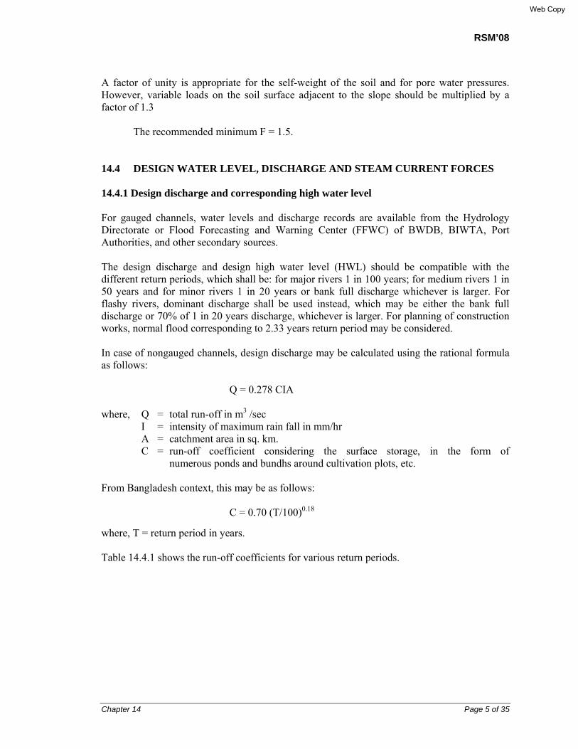
RSM’08
Chapter 14 Page 5 of 35
A factor of unity is appropriate for the self-weight of the soil and for pore water pressures. However, variable loads on the soil surface adjacent to the slope should be multiplied by a factor of 1.3
The recommended minimum F = 1.5.
14.4 DESIGN WATER LEVEL, DISCHARGE AND STEAM CURRENT FORCES 14.4.1 Design discharge and corresponding high water level For gauged channels, water levels and discharge records are available from the Hydrology Directorate or Flood Forecasting and Warning Center (FFWC) of BWDB, BIWTA, Port Authorities, and other secondary sources. The design discharge and design high water level (HWL) should be compatible with the different return periods, which shall be: for major rivers 1 in 100 years; for medium rivers 1 in 50 years and for minor rivers 1 in 20 years or bank full discharge whichever is larger. For flashy rivers, dominant discharge shall be used instead, which may be either the bank full discharge or 70% of 1 in 20 years discharge, whichever is larger. For planning of construction works, normal flood corresponding to 2.33 years return period may be considered.
In case of nongauged channels, design discharge may be calculated using the rational formula as follows:
Q = 0.278 CIA
where, Q = total run-off in m3 /sec I = intensity of maximum rain fall in mm/hr A = catchment area in sq. km. C = run-off coefficient considering the surface storage, in the form of
numerous ponds and bundhs around cultivation plots, etc.
From Bangladesh context, this may be as follows:
C = 0.70 (T/100)0.18
where, T = return period in years.
Table 14.4.1 shows the run-off coefficients for various return periods.
Web Copy
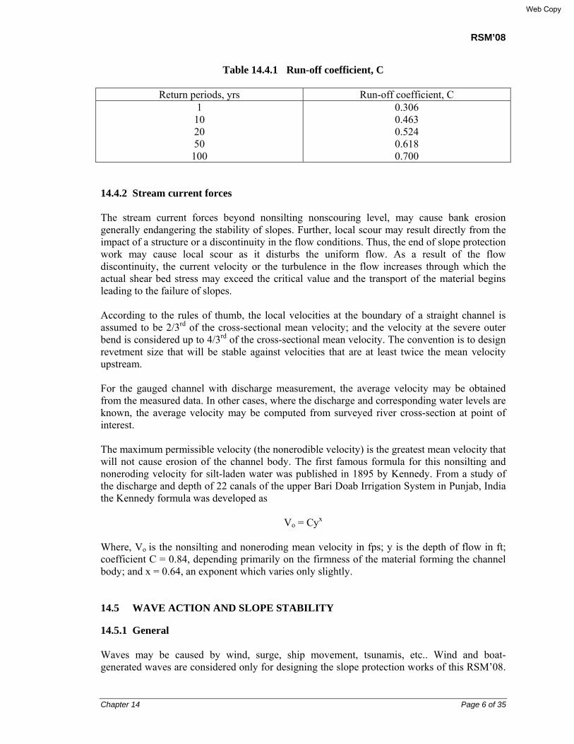
RSM’08
Chapter 14 Page 6 of 35
Table 14.4.1 Run-off coefficient, C
Return periods, yrs Run-off coefficient, C 1
10 20 50 100
0.306 0.463 0.524 0.618 0.700
14.4.2 Stream current forces The stream current forces beyond nonsilting nonscouring level, may cause bank erosion generally endangering the stability of slopes. Further, local scour may result directly from the impact of a structure or a discontinuity in the flow conditions. Thus, the end of slope protection work may cause local scour as it disturbs the uniform flow. As a result of the flow discontinuity, the current velocity or the turbulence in the flow increases through which the actual shear bed stress may exceed the critical value and the transport of the material begins leading to the failure of slopes. According to the rules of thumb, the local velocities at the boundary of a straight channel is assumed to be 2/3rd of the cross-sectional mean velocity; and the velocity at the severe outer bend is considered up to 4/3rd of the cross-sectional mean velocity. The convention is to design revetment size that will be stable against velocities that are at least twice the mean velocity upstream. For the gauged channel with discharge measurement, the average velocity may be obtained from the measured data. In other cases, where the discharge and corresponding water levels are known, the average velocity may be computed from surveyed river cross-section at point of interest. The maximum permissible velocity (the nonerodible velocity) is the greatest mean velocity that will not cause erosion of the channel body. The first famous formula for this nonsilting and noneroding velocity for silt-laden water was published in 1895 by Kennedy. From a study of the discharge and depth of 22 canals of the upper Bari Doab Irrigation System in Punjab, India the Kennedy formula was developed as
Vo = Cyx
Where, Vo is the nonsilting and noneroding mean velocity in fps; y is the depth of flow in ft; coefficient C = 0.84, depending primarily on the firmness of the material forming the channel body; and x = 0.64, an exponent which varies only slightly. 14.5 WAVE ACTION AND SLOPE STABILITY 14.5.1 General Waves may be caused by wind, surge, ship movement, tsunamis, etc.. Wind and boat-generated waves are considered only for designing the slope protection works of this RSM’08.
Web Copy

RSM’08
Chapter 14 Page 7 of 35
Data on boat-generated waves can be obtained by actual measurement, but wind-generated waves are not so easy to measure. It depends upon the wind velocity, duration, direction, fetch, and water depth.
The severity of wave action depends both on their heights and period. The period affects the force of breaking waves, and in turn magnitude of wave uprush.
14.5.2 Wave celerity
The design wave may be determined from observed data or by calculation. The length (L) of an oscillatory wave is equal to its celerity i.e., velocity of propagation of wave (c), multiplied by its period (T). c is related to the water depth below SWL (Standard Water Level), h0, by the equation:
c2 = {(gL/2π) tanh (2 πh0
/L)}.
14.5.3 Wave height
Two simplified equations are used to compute the wave height. For a given wind velocity, Sverdrup and Munk gives the relationship for the maximum possible wave height in meters regardless of fetch (over-water distance of wind action) or duration of wind,
hm = 0.26W2/g
where, hm is the maximum height of wave in m, W is the wind velocity in m/sec, and g is the acceleration due to gravity (g = 9.81 m/sec2).
Stevenson concluded from observation that under the strongest winds the height of the highest waves is proportional to the square of the fetch,
hm = 0.33√F
where, F is the Fetch in km.
This gives for Haor areas, assuming Fetch = 5 km (maximum), hm = 0.74 m.
The wave length at deep water
L0 = gT0.5/2π = 1.56 T0.5
where, L0 = Wave length at deep water (m) T = Wave period (sec)
The largest waves in open water body like Haors, may have a wave length (L) to wave height (H) ratio of about 10:1, though the theoretical ratio is 7:1. In most channels the fetch may generally be insufficient to develop maximum waves (ref: Fig. 14.1). hm and L0 given above is the same as H and L in Fig. 14.1.
Web Copy
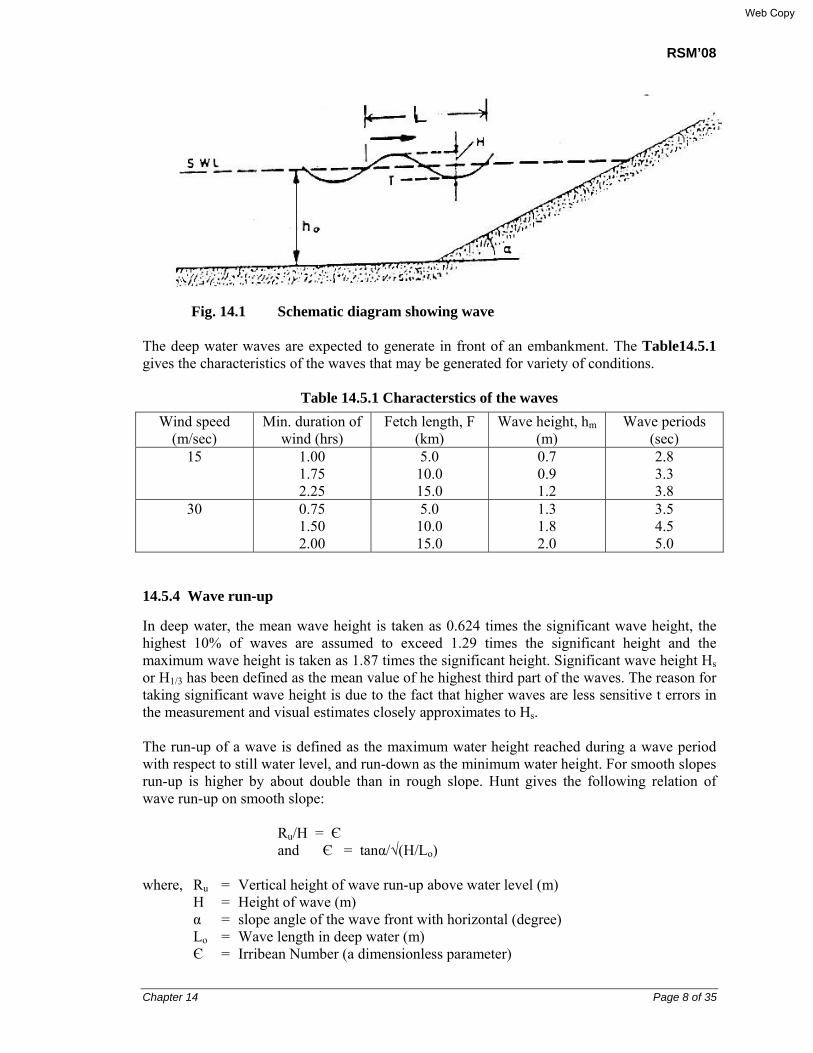
RSM’08
Chapter 14 Page 8 of 35
Fig. 14.1 Schematic diagram showing wave The deep water waves are expected to generate in front of an embankment. The Table14.5.1 gives the characteristics of the waves that may be generated for variety of conditions.
Table 14.5.1 Characterstics of the waves
Wind speed (m/sec)
Min. duration of wind (hrs)
Fetch length, F (km)
Wave height, hm (m)
Wave periods (sec)
15 1.00 1.75 2.25
5.0 10.0 15.0
0.7 0.9 1.2
2.8 3.3 3.8
30 0.75 1.50 2.00
5.0 10.0 15.0
1.3 1.8 2.0
3.5 4.5 5.0
14.5.4 Wave run-up
In deep water, the mean wave height is taken as 0.624 times the significant wave height, the highest 10% of waves are assumed to exceed 1.29 times the significant height and the maximum wave height is taken as 1.87 times the significant height. Significant wave height Hs or H1/3 has been defined as the mean value of he highest third part of the waves. The reason for taking significant wave height is due to the fact that higher waves are less sensitive t errors in the measurement and visual estimates closely approximates to Hs. The run-up of a wave is defined as the maximum water height reached during a wave period with respect to still water level, and run-down as the minimum water height. For smooth slopes run-up is higher by about double than in rough slope. Hunt gives the following relation of wave run-up on smooth slope:
Ru/H = Є and Є = tanα/√(H/Lo)
where, Ru = Vertical height of wave run-up above water level (m) H = Height of wave (m) α = slope angle of the wave front with horizontal (degree) Lo = Wave length in deep water (m) Є = Irribean Number (a dimensionless parameter)
Web Copy

RSM’08
Chapter 14 Page 9 of 35
It’s observed that the boundary between breaker and nobreaker wave is Є = 2.5 – 3.0. The waves with Є = 3 to 5 is often known as surging wave, and the wave with Є = 0.5 – 2.5 is known as plunging wave. With decreasing slope of wave front (Є < 0.5) the crest becomes less pronounced and wave may spill over slope, which is called spilling wave. For the type of embankment slope say 1(V) : 2(H), and with Fetch F<1.0 km, Є =1.0 approximately. Thus the normal free board should suffice to take care about the wave run-up. For slope protection works of embankment facing Haor, it should be ensured that the free board is larger than the wave height plus wave run-up; and slope protection should extend higher than the wave run-up. 14.6 SCOUR The protection of toe of any slope protection works is of prime importance as regards the stability of overall slope protection against scour.
Lacey’s regime formula is widely used to find out scour depth in unconstricted alluvial rivers. For narrow channels scour depth may be calculated using the total discharge Q as below:
dsm = 0.47 (Q/f)1/3
where, dsm = the general scour depth at design discharge below HWL, m Q = the discharge, m3/sec f = Lacey’s silt factor = 1.76√dm dm = weighted mean diameter of sediment particles in mm.
To estimate the maximum scour depth, a multiplying factor to dsm must be used. The Table 14.6.1 below gives the coefficients recommended by IRC : 5 -1985.
Table 14.6.1 Empirical multiplying factors for maximum scour depth
Nature of location Factor
Straight reach of channel Moderate bend Severe bend Right angled bend Noses of piers Noses of guide banks
1.27 1.50 1.75 2.00 2.00 2.75
Also refer to ‘Chapter 4 Hydraulic Considerations and Clearance’ for further relevant information as regards river hydraulics.
Web Copy

RSM’08
Chapter 14 Page 10 of 35
14.7 DESIGN OF SLOPE PROTECTION WORKS 14.7.1 Slope revetment Neill has developed a design graph to determine the weight and size of armor, for slope protection works using spherical stones (specific gravity Gs =2.65) and for bank slopes 1(V) : 2(H). (Refer: Plate 1, reproduced from BWDB Standard Design Manual, Volume-I: Standard Design Criteria), prepared based on Neill’s equation for determining the size of stones or CC blocks). The following equation developed by Neill has been fitted to the curve of Plate I:
D = 0.034V2 (metric unit).
where, D = Diameter of the stone (m)
V = impinging stream velocity (m/sec). In place of stone, CC block of equivalent weight may also be used.
Web Copy
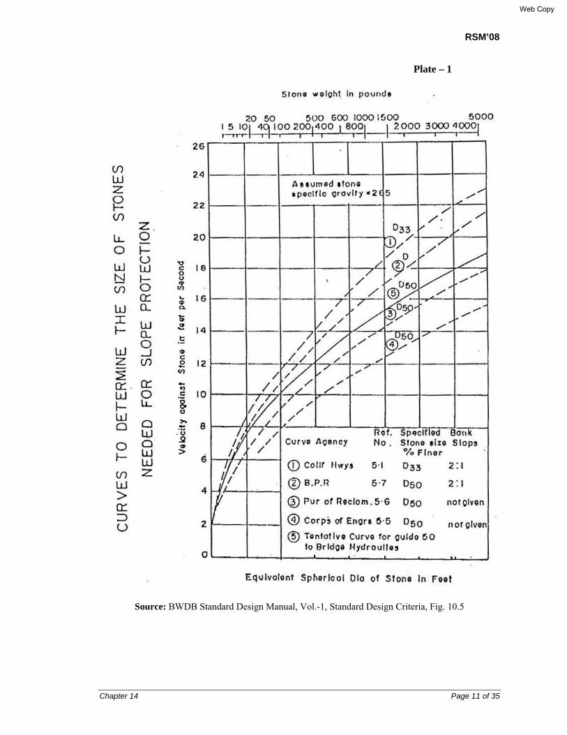
RSM’08
Chapter 14 Page 11 of 35
Plate – 1
Source: BWDB Standard Design Manual, Vol.-1, Standard Design Criteria, Fig. 10.5
Web Copy
RSM’08
Chapter 14 Page 12 of 35
14.7.2 Types of slope protection works The protective works involve a suitable hard material applied on the slope and toe of the embankment so that the fill material of the slope is protected against the erosive forces of flowing water and dynamic actions of waves. Revetments are of two types:
• Open joint type in which joint gaps between individual hard materials remains open
allowing free flow of water.
• Close joint type in which joint gaps between individual hard materials are sealed.
For slope protection works of the RSM’08 bridge/culvert approaches, open joint type is provided, to release build-up of excess hydrostatic pressure behind the revetment. The following open joint types of slope protection works are proposed:
• Type-I Slope Protection Works with Grass Turfing (Dwg. No. RSMSPW-01)
• Type-II Slope Protection Works with Gunny bags over Geotextile (Dwg. No. RSMSPW-02)
• Type-III Slope Protection Works with CC blocks over Geotextile (Dwg. No. RSMSPW-03)
• Type-IV Slope Protection Works with Brick blocks over Geotextile (Dwg. No. RSMSPW-04)
• Type-V Slope Protection Works with RC Slab over Geotextile with Palisading at Toe (Dwg. No. RSMSPW-05)
• Type-VI Slope Protection Works with Launching Apron (Dwg. No. RSMSPW-06)
• Type-VII Slope Protection Works with Articulated Concrete Mattress (Dwg. No. RSMSPW-07)
• Type-VIII Revetment over Geo-jute mat (Dwg. No. RSMSPW-08)
3 types of toe wall are proposed for Types II, III and IV:
• Type-A Brick masonry
• Type-B 150 mm x 150mm x 2000 mm RC pile
• Type-C 150 mm x 150mm x 3000 mm RC pile
Web Copy
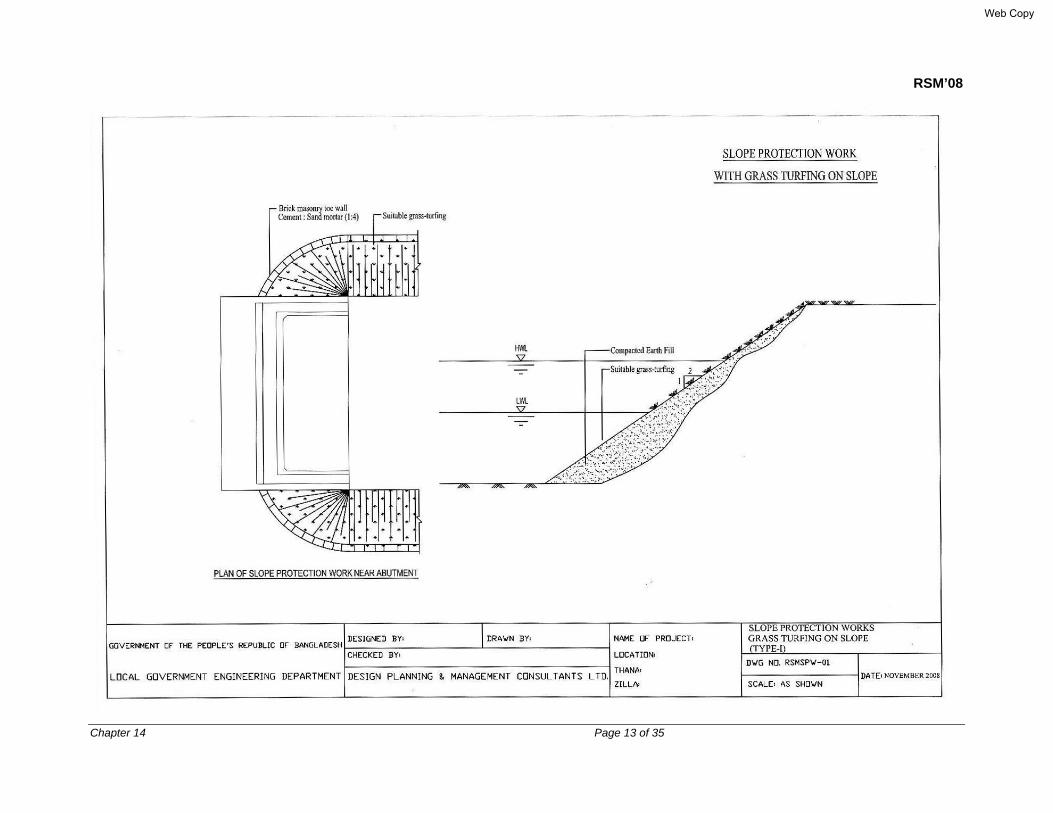
RSM’08
Chapter 14 Page 13 of 35
Web Copy

RSM’08
Chapter 14 Page 14 of 35
Web Copy
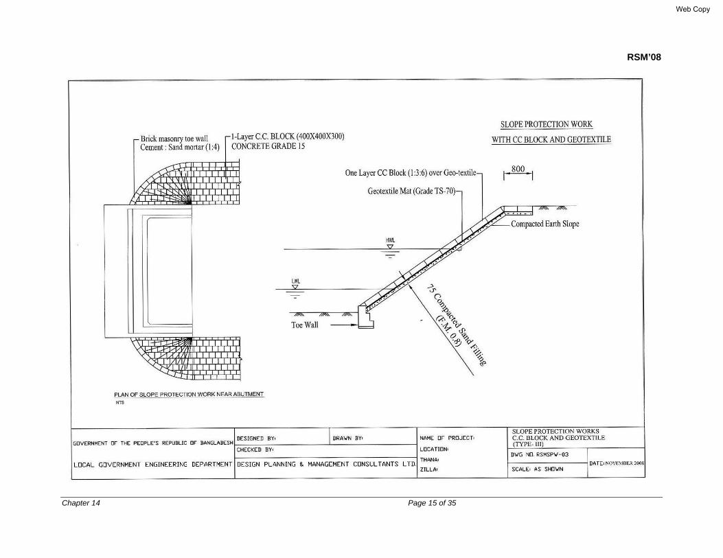
RSM’08
Chapter 14 Page 15 of 35
Web Copy

RSM’08
Chapter 14 Page 16 of 35
Web Copy

RSM’08
Chapter 14 Page 17 of 35
Web Copy
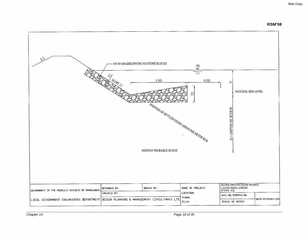
RSM’08
Chapter 14 Page 18 of 35
Web Copy

RSM’08
Chapter 14 Page 19 of 35
Web Copy
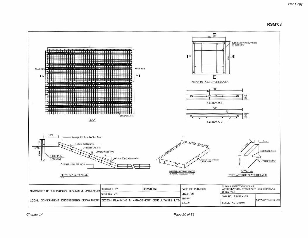
RSM’08
Chapter 14 Page 20 of 35
Web Copy
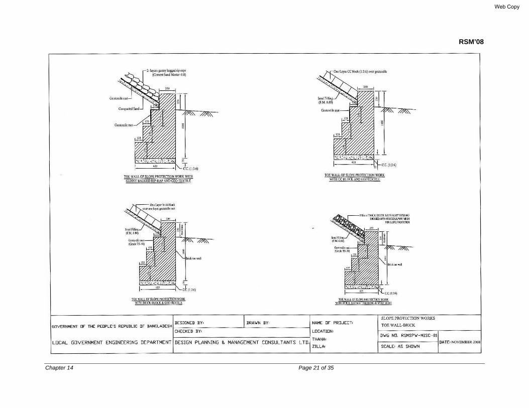
RSM’08
Chapter 14 Page 21 of 35
Web Copy

RSM’08
Chapter 14 Page 22 of 35
Web Copy
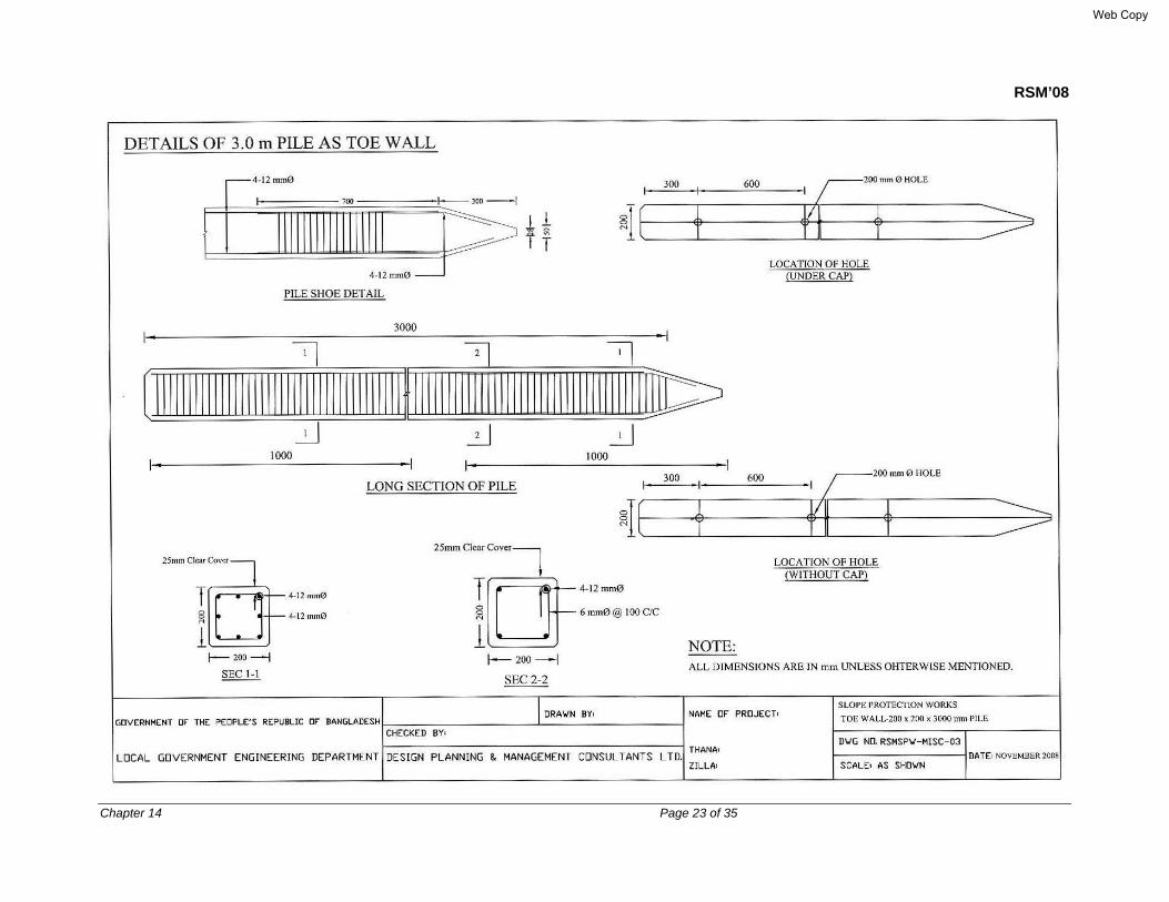
RSM’08
Chapter 14 Page 23 of 35
Web Copy

RSM’08
Chapter 14 Page 24 of 35
14.7.2.1 Type-I Grass turfing
For embankments where the low water level (LWL) remains at or below embankment toe level during lean period, and the fill material particularly at the top 300 mm of the slope surface comprises cohesive-friction soil, such protection is appropriate. This may also be found suitable as a protection of the compacted fill material of the sloping surface around the abutment-wing walls where LWL is nearer to the toe line (refer to Dwg. No. RSMPW – 01 for the typical design). This work shall consist of furnishing turf and sods as required and planting them to give a healthy stable covering of grass which will maintain its growth in any weather and prevent erosion of the material in which it is planted.
a) Materials
Grass shall be of the species native to Bangladesh, harmless and inoffensive to persons and animals and not of a kind recognized as a nuisance to agriculture. It shall be free from disease and noxious weeds, deep rooted and sufficiently rapid growing and spreading to give complete cover over the planted area within the Maintenance Period. The term “grass” embraces turf and sods and if the Engineer permits, may include plants of other types capable of giving effective protection. Fertilizer shall be approved lime or mixtures of plant nutrients or both.
b) Construction Methods
The work shall be carried out by planting sods or turfs to give continuous cover over the whole area. This shall be planted with their root system substantially undamaged, well buried in firm material and packed around with moist earth in which they have grown. Grass shall be planted at an earlier stage of construction so that at the time of the final inspection, all areas are substantially covered with healthy, well-established, firmly rooted grass. Fertilizer shall be added at the time of planting if necessary to ensure good ground cover within the required time.
14.7.2.2 Type-II Gunny bag over geotextile mat with toe wall
This is provided where the embankment fill material is predominantly granular and the toe level becomes dry during lean period. The toe walls will be of the following types:
• Brick masonry toe wall • 150 mm x 150 mm x 2000 mm RC pile • 200 mmx200 mm x 3000 mm RC pile
Slope protection of the sloping surface of the compacted granular backfill material around abutment wing wall using cement: sand (1:8) filled gunny bags of 50/75 kg weight are suitable where LWL during the lean period falls below the toe line.
Brick masonry toe wall will be provided where negligible scour is expected along toe line. 150 mm x 150 mm x 2000 mm RC pile will be provided where the estimated scour is less than
Web Copy

RSM’08
Chapter 14 Page 25 of 35
about 750 mm. 200 mm x 200 mm x 3000 mm RC pile will be provided where the estimated scour is less than about 1000 mm.
14.7.2.3 Type-III CC blocks over geotextile mat
This design is the same as Type-II; excepting that CC (plain concrete) blocks will be used in place of the sand filled gunny bags. This is provided where the stream current force and/or wave attack is appreciable. These CC blocks shall be made of Class 15 concrete (ref. Part –A, Article 7.7). This will be underlain by 150 mm thick inverted granular filter using 25 mm downgraded 1st Class or picked Jhama brick chips, or over geotextile mat as shown on the drawing.
The slope will be prepared as designed; then 75mm thick compacted granular fill (FM 0.8) will be provided. The concrete blocks will thereafter be placed over the geotextile mats (For details, refer to Dwg. No. RSMSPW-03). The toe wall shall be either of the 3 types as shown under Article 14.3.2.
14.7.2.4 Type-IV Brick blocks over geotextile mat
The design will be the same as Type-III, excepting that brick blocks having cement: sand mortar (1: 6) shall be used. The rest of the details shall be the same as of Type-III design (For details, refer to Dwg. No. RSMSPW-03). Bricks shall be manufactured from clay or shale or a combination of these materials and shall be uniformly burnt throughout. They shall be hard and sound a give a clear metallic ring when struck with a small hammer or another brick and should not break when dropped to the earth from a height of 1.5m with one brick above another the formation of a “T”. The surface should be too hard to be scratched with the fingernail as specified by LGED Specifications. Crushing strength of a first class brick should be 170 kg/cm2 and not less than 140kg/cm2 whereas maximum water absorption capacity should be 20% of dry weight. The proper dimensions will be 240mm x 115mm x 70mm.
14.7.2.5 Type-V RC pile with plate and palisading works at toe
This is provided where appreciable scour might occur at embankment toe line and construction needs to be done below LWL. In this type, 1(V):2(H) slope line will be built with compacted sand fill. Then, about 3.00 m long 150 mm x 150 mm RC pile will be provided at about 900 mm spacing, of which about 60% length will be driven below bed level. Thereafter, 75 mm thick RC plate will be placed behind and anchored with the piles by nuts and bolts as shown on the drawings. One layer sand filled gunny bags will then be placed behind protecting the sand filled slope line.
14.7.2.6 Type-VI Revetment with launching apron
It’s placed at the toe of the slope revetment works, as toe protection method of revetment mainly for river bank protection works. In it launching stones or blocks are placed over expected scour areas at an elevation above the zone of attack. The stone from the apron gradually falls and goes on covering the slope as scour takes place and this process is called
Web Copy

RSM’08
Chapter 14 Page 26 of 35
"launching”. The principle of launching apron of loose stones is that as scour takes place it will drop in the scour hole to provide the protection. The volume of stones or blocks should suffice to cover the sloping surface of the scour hole. Launch slope is less predictable if cohesive material is present, since cohesive material may fail in large blocks. Inglis gave the following formula to compute thickness of stone for launching apron:
T = 0.06 Q1/3 where, T = thickness of stone riprap in feet Q = Discharge in cfs. The thickness determined above should be increased by 50% when it’s placed under water to keep provision for uncertainties associated with this type of placement. Spring (1903) recommended a minimum thickness of apron equal to 1.25 times the thickness of stone riprap of the revetment in slope. He further recommended that the thickness of apron at the junction of apron and slope should be the same as laid on the slope but should be increased in the shape of a wedge towards the channel bed. Since the apron stone shall have to be laid mostly under water and cannot be hand placed, thickness of the apron at junction, according to Rao (1946), should be 1.50 times the thickness of riprap in slope. The thickness of channel end of apron in such case shall be 2.25 times the thickness of riprap in slope. The length of apron as recommended by Englis (1949) is to be 1.5D, where D is the design scour depth below the position of laying. 14.7.2.7 Revetment against wave action Hudson equation is used to determine the size of revetment material required to resist wave forces as follows:
W = H3 ρ tanӨ/k∆3
where, W = Weight of revetment material, kN/m3 H = Significant wave height, m ρ = Density of revetment material, kN/m3 Ө = Embankment slope angles at toe k = A coefficient varying from 3.2 for smooth quarry stone to 10 for tetrapod ∆ = Relative density of revetment material = (ρ - ρw)/ ρw ρw Density of water The empirical form of Hudson’s equation in fps unit with k=3.2, is
W50 = [(19.5Gs H3)/{( Gs – 1)3 Cot Ө)}]
Web Copy

RSM’08
Chapter 14 Page 27 of 35
where, W50 = 50% passing rock weight in pound Gs = Specific gravity of rock material
The solution of this equation is shown graphically in Plate-2 (reproduced from BWDB Standard Design Manual, Vol.-1, Standard Design Criteria, Fig. 10.6). The graph reads W50 of rock in pounds using significant wave height Hs (same as H above), embankment slope Cotα (same as tanӨ), and specific gravity Gs. The rock weight in pound will then be converted to CC blocks in kg as before.
14.7.2.8 Type-VII Articulated concrete mattress The articulated concrete mattress comprises series of thin concrete slabs with light reinforcement placed over the prepared or dressed slope like flower wreaths using steel wires as connecting string. The size of the blocks may be around 1000 mm x 1000 mm x 100 mm. The blocks may be underlain by geo-textile filter mats. US Army Corps of Engineers first used it in the river training/bank protection works of the Colorado River. They developed special launching vessels to launch the prepared block mattresses from the river end towards banks. In Bangladesh, the launching arrangement may be made using boats or specially prepared barges. 14.7.2.9 Type-VIII Revetment with Geo-jute Where specified on the Drawings, Geo-jute shall be laid on the finished soil profiles/slopes, in place of geotextile mats below revetment. The detailed application methods may differ from site to site but generally the steps are as follows:
• Geo-jute is rolled along or down slopes and secured with wire staples.
• Geo-jute must be laid loosely and evenly without tension or stretch on either direction.
Web Copy

RSM’08
Chapter 14 Page 28 of 35
Plate - 2
Web Copy

RSM’08
Chapter 14 Page 29 of 35
• Up-channel ends./embankment crest ends or shoulders are buried and stapled in a 150mm deep slit trench, and then fastened with a further five staples.
• Down-channel ends/embankment toes are under folded by 150mm and secured with five staples.
• All terminations are buried in a 150mm deep slit trench.
• Longitudinal edges are overlapped by 100mm and stapled at 100cm centers.
• Roll junctions are overlapped by 100mm and stapled.
• An additional row of staples is fixed at 100cm centered down each strip.
• Erosion stops of folded Geo-jute may be buried at critical pints to control subsoil slippage as and when directed by the Engineer.
14.8 DESIGN OF FILTER 14.8.1 Filter design principle The stability of the whole revetment depends on the type and composition of the filter layer. A filter should prevent excessive migration of soil particles, while allowing relatively unimpeded flow of liquid from the soil. The function of a filter is:
• to prevent migration of subsoil particles out of the bank slope (Retention Criteria); and
• to allow at the same time movement of water through the filter (Permeability Criteria) The filter may consist of one of the following type of material:
• granular filter, made of loose, bounded or packed grains; and
• fiber filter, made of synthetic or natural materials The design of the filter layer must also take realistic account of construction constraints and consolidation of the subsoil following the construction Important soil parameters to be calculated using results of the soil tests are:
• coefficient of uniformly, Cu’ from particle size distribution: cu = d60/d10
• linear coefficient of uniformity, C′u’ from particle size distribution:
C′u = d′50/d′0 = d′60/d′10 = d′70/d′20 =d′100/d′50 = (d′100/d′0)1/2
coefficient of curvature, Cc, from particle size distribution:
Cc = 3060
1030
//dddd
=1060
230)(xdd
d
hydraulic conductivity of soil, can be measured from direct permeability testing; if testing is not possible, then the hydraulic conductivity can be estimated from the particles size distribution (fig. 10.9)
Web Copy

RSM’08
Chapter 14 Page 30 of 35
14.8.2 Granular Filter Conventional gravity filter design requires consideration both the retention capability and the permeability of the granular filter. The inverted filter shall be designed using the following criteria: The gradation of filter should conform to the following rule,
albasemateridrialfiltermated
8515
≤5
albasemateridrialfiltermated
5050 <p
≤q
Filter type P q
For homogenous and round grains For homogenous sharp grains (Sylhet sand) For graded grains (sized khoa, stone chips)
5 – 10 10 – 30 12 – 60
5 – 10 6 – 20 12 - 40
(b) The sieve curves of all layers should be almost parallel in the area of the smaller
fractions. (c) Minimum layer thickness Sand - 0.10 m Gravel - 0.20 m Stone - 2 times stone diameter An analysis of the retention criteria shows that if the pore spaces in granular filters are small enough to retain the coarsest 15% (i.e.d15 size) of the adjacent soil, then the majority of the finer soil particles will also be retained. 14.8.3 Fibre Filter The criteria for geotextile filter selection are as follows:
• Retention criteria to ensure that the geotextile openings are small enough to prevent excessive migration of sol particles.
• Permeability criterion to ensure that the geotextile is permeable enough to allow liquids to pass through it without significant flow impedance
• Anti-clogging criterion to ensure that the geotextile has enough openings so that if soil becomes entrapped within the geotextile and clogs a few openings, the permeability of filter will not be significantly hampered.
• Survivability criterion to ensure that the geotextile survives its installation.
• Durability criterion to ensure that the geotextile is durable enough to withstand adverse chemicals, ultraviolet exposure, and abrasive environments for the design life.
albasemateridrialfiltermated
1515
Web Copy

RSM’08
Chapter 14 Page 31 of 35
PIANC (1987a) provides following general criteria for design of fibre filter: (a) Retention
• For soils with a uniformity coefficient less than 5: 0.05 mm < 090 < 0.7 d90 • For soils with a uniformity coefficient grater than 5: 0.05 mm < 090 < d90
(b) Permeability
Ψ > 5x10³ * Ks * i where,
Ψ = permeability of geotextile (1/s) Ks = Permeability of the subsoil (m/s) i = Hydraulic gradient in the soil
14.8.4 Placement of Riprap over Filter material 14.8.4.1 General requirement Common methods of riprap placement are hand placing, machine placing, such as from a skip, dragline or some form of bucket. Hand placement produces the most stable riprap revetment. This reduces the required volume of hard material. The layer thickness and stone size may be increased somewhat to offset the short comings of placement method. Thickness of underwater placement should be increased by 50% to provide for the uncertainties associated with the type of placement. The stability of the whole revetment depends on the type Inverted Filter materials shall constitute layers of inverted graded filter materials with finer materials placed at the bottom and coarser material at the top. a) Fine Filter Material The fine filter shall comprise of sand and comply with the grading shown on the Drawings. b) Coarse Filter Material
Coarse filter material shall be made from either:
• Breaking first class or picked jhama bricks as specified.
• Gravel (shingle) or broken stone of hard durable rock. The stone delivered to the works shall be rejected if not perfectly clean and if it contains soft, clayey, shaley or decomposed stone. The stone may be broken in a stone crusher of approved type or manually. Any dust or fine material below 5mm in size made in the stone crusher is to be removed by screening and the stone shall be thoroughly washed by an approved method.
Filter materials be laid in two layers of equal thickness. The filter material in the bottom layer shall be well graded between 5mm to 20mm and the filter material of the top layer shall be well graded between 20mm to 40mm or in accordance with the gradings shown on the Drawings.
Web Copy
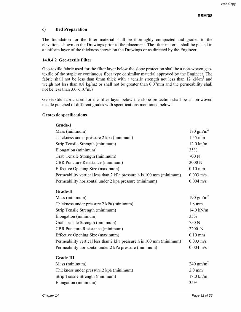
RSM’08
Chapter 14 Page 32 of 35
c) Bed Preparation
The foundation for the filter material shall be thoroughly compacted and graded to the elevations shown on the Drawings prior to the placement. The filter material shall be placed in a uniform layer of the thickness shown on the Drawings or as directed by the Engineer. 14.8.4.2 Geo-textile Filter
Geo-textile fabric used for the filter layer below the slope protection shall be a non-woven geo-textile of the staple or continuous fiber type or similar material approved by the Engineer. The fabric shall not be less than 6mm thick with a tensile strength not less than 12 kN/m2 and weigh not less than 0.8 kg/m2 or shall not be greater than 0.07mm and the permeability shall not be less than 3.0 x 10³m/s
Geo-textile fabric used for the filter layer below the slope protection shall be a non-woven needle punched of different grades with specifications mentioned below:
Geotextle specifications
Grade-1 Mass (minimum) 170 gm/m2 Thickness under pressure 2 kpa (minimum) 1.55 mm Strip Tensile Strength (minimum) 12.0 kn/m Elongation (minimum) 35% Grab Tensile Strength (minimum) 700 N CBR Puncture Resistance (minimum) 2000 N Effective Opening Size (maximum) 0.10 mm Permeability vertical less than 2 kPa pressure h is 100 mm (minimum) 0.003 m/s Permeability horizontal under 2 kpa pressure (minimum) 0.004 m/s Grade-II Mass (minimum) 190 gm/m2 Thickness under pressure 2 kPa (minimum) 1.8 mm Strip Tensile Strength (minimum) 14.0 kN/m Elongation (minimum) 35% Grab Tensile Strength (minimum) 750 N CBR Puncture Resistance (minimum) 2200 N Effective Opening Size (maximum) 0.10 mm Permeability vertical less than 2 kPa pressure h is 100 mm (minimum) 0.003 m/s Permeability horizontal under 2 kPa pressure (minimum) 0.004 m/s Grade-III Mass (minimum) 240 gm/m2 Thickness under pressure 2 kpa (minimum) 2.0 mm Strip Tensile Strength (minimum) 18.0 kn/m Elongation (minimum) 35%
Web Copy
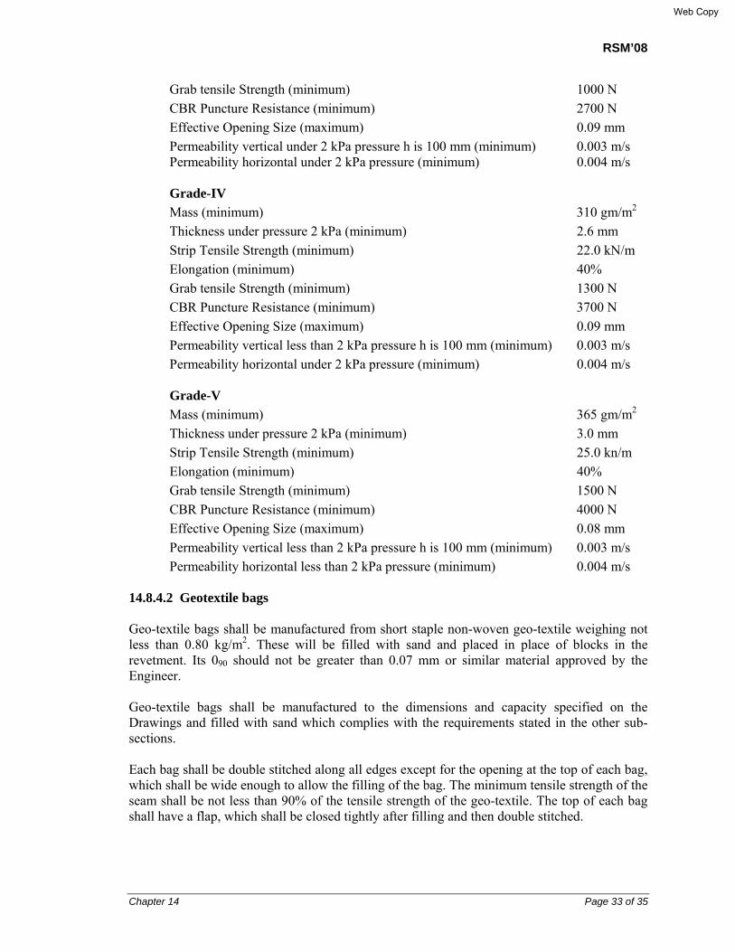
RSM’08
Chapter 14 Page 33 of 35
Grab tensile Strength (minimum) 1000 N CBR Puncture Resistance (minimum) 2700 N Effective Opening Size (maximum) 0.09 mm Permeability vertical under 2 kPa pressure h is 100 mm (minimum) 0.003 m/s Permeability horizontal under 2 kPa pressure (minimum) 0.004 m/s Grade-IV Mass (minimum) 310 gm/m2 Thickness under pressure 2 kPa (minimum) 2.6 mm Strip Tensile Strength (minimum) 22.0 kN/m Elongation (minimum) 40% Grab tensile Strength (minimum) 1300 N CBR Puncture Resistance (minimum) 3700 N Effective Opening Size (maximum) 0.09 mm Permeability vertical less than 2 kPa pressure h is 100 mm (minimum) 0.003 m/s Permeability horizontal under 2 kPa pressure (minimum) 0.004 m/s Grade-V Mass (minimum) 365 gm/m2 Thickness under pressure 2 kPa (minimum) 3.0 mm Strip Tensile Strength (minimum) 25.0 kn/m Elongation (minimum) 40% Grab tensile Strength (minimum) 1500 N CBR Puncture Resistance (minimum) 4000 N Effective Opening Size (maximum) 0.08 mm Permeability vertical less than 2 kPa pressure h is 100 mm (minimum) 0.003 m/s Permeability horizontal less than 2 kPa pressure (minimum) 0.004 m/s
14.8.4.2 Geotextile bags Geo-textile bags shall be manufactured from short staple non-woven geo-textile weighing not less than 0.80 kg/m2. These will be filled with sand and placed in place of blocks in the revetment. Its 090 should not be greater than 0.07 mm or similar material approved by the Engineer. Geo-textile bags shall be manufactured to the dimensions and capacity specified on the Drawings and filled with sand which complies with the requirements stated in the other sub-sections. Each bag shall be double stitched along all edges except for the opening at the top of each bag, which shall be wide enough to allow the filling of the bag. The minimum tensile strength of the seam shall be not less than 90% of the tensile strength of the geo-textile. The top of each bag shall have a flap, which shall be closed tightly after filling and then double stitched.
Web Copy
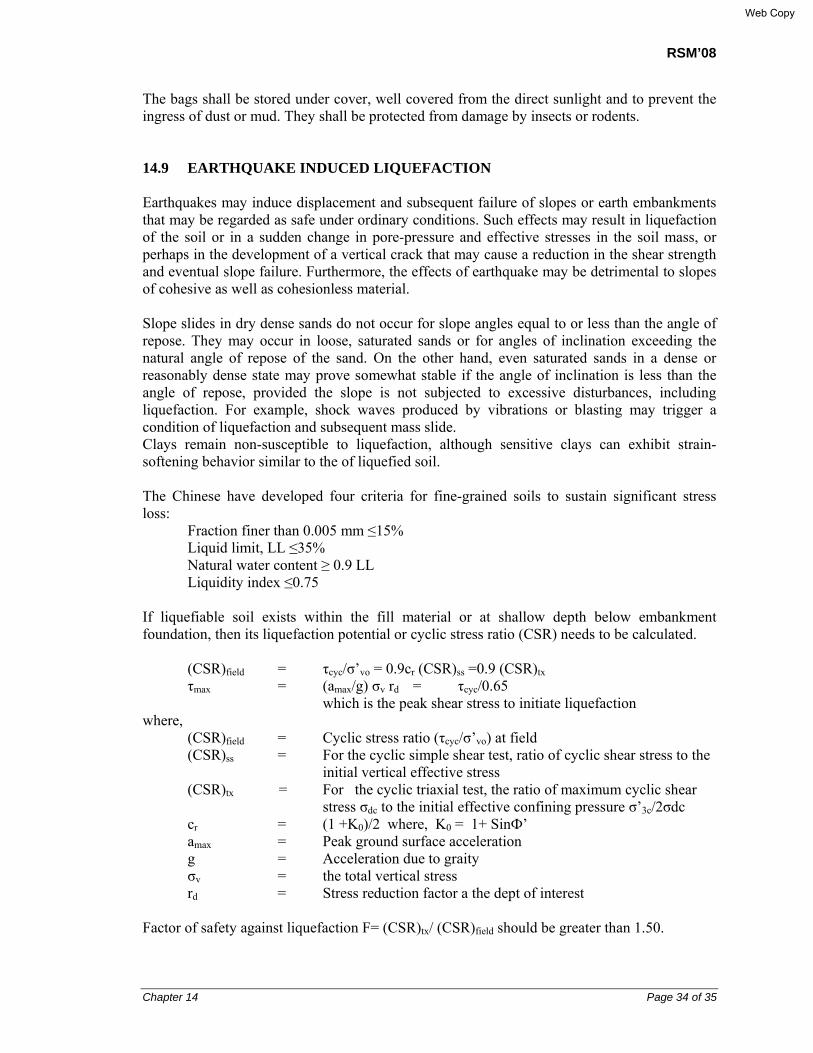
RSM’08
Chapter 14 Page 34 of 35
The bags shall be stored under cover, well covered from the direct sunlight and to prevent the ingress of dust or mud. They shall be protected from damage by insects or rodents. 14.9 EARTHQUAKE INDUCED LIQUEFACTION Earthquakes may induce displacement and subsequent failure of slopes or earth embankments that may be regarded as safe under ordinary conditions. Such effects may result in liquefaction of the soil or in a sudden change in pore-pressure and effective stresses in the soil mass, or perhaps in the development of a vertical crack that may cause a reduction in the shear strength and eventual slope failure. Furthermore, the effects of earthquake may be detrimental to slopes of cohesive as well as cohesionless material. Slope slides in dry dense sands do not occur for slope angles equal to or less than the angle of repose. They may occur in loose, saturated sands or for angles of inclination exceeding the natural angle of repose of the sand. On the other hand, even saturated sands in a dense or reasonably dense state may prove somewhat stable if the angle of inclination is less than the angle of repose, provided the slope is not subjected to excessive disturbances, including liquefaction. For example, shock waves produced by vibrations or blasting may trigger a condition of liquefaction and subsequent mass slide. Clays remain non-susceptible to liquefaction, although sensitive clays can exhibit strain-softening behavior similar to the of liquefied soil. The Chinese have developed four criteria for fine-grained soils to sustain significant stress loss: Fraction finer than 0.005 mm ≤15% Liquid limit, LL ≤35% Natural water content ≥ 0.9 LL Liquidity index ≤0.75 If liquefiable soil exists within the fill material or at shallow depth below embankment foundation, then its liquefaction potential or cyclic stress ratio (CSR) needs to be calculated. (CSR)field = τcyc/σ’vo = 0.9cr (CSR)ss =0.9 (CSR)tx τmax = (amax/g) σv rd = τcyc/0.65 which is the peak shear stress to initiate liquefaction where, (CSR)field = Cyclic stress ratio (τcyc/σ’vo) at field (CSR)ss = For the cyclic simple shear test, ratio of cyclic shear stress to the initial vertical effective stress
(CSR)tx = For the cyclic triaxial test, the ratio of maximum cyclic shear stress σdc to the initial effective confining pressure σ’3c/2σdc
cr = (1 +K0)/2 where, K0 = 1+ SinФ’ amax = Peak ground surface acceleration g = Acceleration due to graity σv = the total vertical stress rd = Stress reduction factor a the dept of interest Factor of safety against liquefaction F= (CSR)tx/ (CSR)field should be greater than 1.50.
Web Copy

RSM’08
Chapter 14 Page 35 of 35
References
1. Rai Bahadur A. N. Khosla, Dr. N. K. Bose & Dr. E. Mckenzie Taylor, Central Board of India, Publication No. 12, New Delhi (Reprint)
2. BWDB, Standard Design Manual, Volume-I: Standard Design Criteria, prepared by Sandard Design Manual Committee, December 1994
3. Dr. M. Monowar Hossain, TU Deft – BUET, Lecture Notes on River Engineering, Volume-1 River Engineering (General) & Volume-2 River Engineering (Structural Aspects of River Training Works, July 1993
4. AASHTO LRFD Bridge Design Specifications SI Units, 2007
5. Road Design Standards of Bangladesh Government, 2004 (Bangladesh Gazette, Additional, September 5, 2004, No. PC/TS/Roads/Standard-10 (Volume-2)/03-649)
6. Ven Te Chow, Handbook of Applied Hydrology, 1964
7. BUET-IWM, Manual on Hydrologic and Hydraulic Design of Bridges, August 2008.
Web Copy