MP 40.7 168 Deck Plate Girder 3 spans - 53’6” + 53’6” + 61 ...

DEVELOPMENT AND EVALUATIONOF AN ADHESIVELY BONDED PANEL-TO-PANEL
JOINT FOR A FIBER-REINFORCED POLYMERBRIDGE DECK SYSTEM
FINALCONTRACT REPORT
VTRC 07-CR14
http://www.virginiadot.org/vtrc/main/online_reports/pdf/07-cr14.pdf
ZIHONG LIUGraduate Research Assistant
Via Department of Civil and Environmental Engineering
PRASUN K. MAJUMDARGraduate Research Assistant
Department of Engineering Science and Mechanics
Virginia Polytechnic Institute & State University
TOMMY COUSINS, Ph.D., P.E.Associate Professor
Via Department of Civil and Environmental Engineering
JOHN J. LESKO, Ph.D.Professor
Department of Engineering Science and Mechanics

Standard Title Page - Report on Federally Funded Project 1. Report No. 2. Government Accession No. 3. Recipient’s Catalog No. FHWA/VTRC 07-CR14
4. Title and Subtitle 5. Report Date Development and Evaluation of an Adhesively Bonded Panel-to-Panel Joint for a Fiber-Reinforced Polymer Bridge Deck System
April 2007
6. Performing Organization Code 7. Author(s) Zihong Liu, Prasun K. Majumdar, Tommy Cousins, and John J. Lesko
8. Performing Organization Report No. VTRC 07-CR14
9. Performing Organization and Address 10. Work Unit No. (TRAIS) Virginia Transportation Research Council
530 Edgemont Road 11. Contract or Grant No. Charlottesville, VA 22903
69583
12. Sponsoring Agencies' Name and Address 13. Type of Report and Period Covered Virginia Department of Transportation
Federal Highway Administration
Final Contract Report
1401 E. Broad Street 400 North 8th Street, Room 750 14. Sponsoring Agency Code Richmond, VA 23219 Richmond, VA 23219-4825 15. Supplementary Notes 16. Abstract A fiber-reinforced polymer (FRP) composite cellular deck system was used to rehabilitate a historical cast iron thru-truss structure (Hawthorne Street Bridge in Covington, Virginia). The most important characteristic of this application is reduction in self-weight, which raises the live load-carrying capacity of the bridge by replacing the existing concrete deck with an FRP deck. This bridge is designed to an HL-93 load and has a 75-ft clear span with a roadway width of 22 ft. The panel-to-panel connections were accomplished using full width, adhesively (structural urethane adhesive) bonded tongue and groove splices with scarfed edges. To ensure proper construction, serviceability, and strength of the splice, a full-scale two-bay section of the bridge with three adhesively bonded panel-to-panel connections was constructed and tested in the Structures Laboratory at Virginia Tech. Test results showed that no crack initiated in the joints under service load and no significant change in stiffness or strength of the joint occurred after 3,000,000 cycles of fatigue loading. The proposed adhesive bonding technique was installed in the bridge in August 2006.
17 Key Words 18. Distribution Statement Fiber-reinforced polymer, bridge decks, composite material, bridge deck replacement, bridge rehabilitation
No restrictions. This document is available to the public through NTIS, Springfield, VA 22161.
19. Security Classif. (of this report) 20. Security Classif. (of this page) 21. No. of Pages 22. Price Unclassified Unclassified 26
Form DOT F 1700.7 (8-72) Reproduction of completed page authorized

FINAL CONTRACT REPORT
DEVELOPMENT AND EVALUATION OF AN ADHESIVELY BONDED PANEL-TO-PANEL JOINT FOR A FIBER-REINFORCED POLYMER
BRIDGE DECK SYSTEM
Zihong Liu Graduate Research Assistant
Via Department of Civil and Environmental Engineering
Prasun K. Majumdar Graduate Research Assistant
Department of Engineering Science and Mechanics
Tommy Cousins, Ph.D., P.E. Associate Professor
Via Department of Civil and Environmental Engineering
John J. Lesko, Ph.D. Professor
Department of Engineering Science and Mechanics
Virginia Polytechnic Institute & State University
Project Manager Jose P. Gomez, Ph.D., P.E., Virginia Transportation Research Council
Contract Research Sponsored by the Virginia Transportation Research Council
Virginia Transportation Research Council (A partnership of the Virginia Department of Transportation
and the University of Virginia since 1948)
In Cooperation with the U.S. Department of Transportation Federal Highway Administration
Charlottesville, Virginia
April 2007
VTRC 07-CR14
ii
NOTICE
The project that is the subject of this report was done under contract for the Virginia Department of Transportation, Virginia Transportation Research Council. The contents of this report reflect the views of the authors, who are responsible for the facts and the accuracy of the data presented herein. The contents do not necessarily reflect the official views or policies of the Virginia Department of Transportation, the Commonwealth Transportation Board, or the Federal Highway Administration. This report does not constitute a standard, specification, or regulation. Each contract report is peer reviewed and accepted for publication by Research Council staff with expertise in related technical areas. Final editing and proofreading of the report are performed by the contractor.
Copyright 2007 by the Commonwealth of Virginia. All rights reserved.

iii
ABSTRACT
A fiber-reinforced polymer (FRP) composite cellular deck system was used to rehabilitate a historical cast iron thru-truss structure (Hawthorne Street Bridge in Covington, Virginia). The most important characteristic of this application is reduction in self-weight, which raises the live load-carrying capacity of the bridge by replacing the existing concrete deck with an FRP deck. This bridge is designed to an HL-93 load and has a 75-ft clear span with a roadway width of 22 ft. The panel-to-panel connections were accomplished using full width, adhesively (structural urethane adhesive) bonded tongue and groove splices with scarfed edges. To ensure proper construction, serviceability, and strength of the splice, a full-scale two-bay section of the bridge with three adhesively bonded panel-to-panel connections was constructed and tested in the Structures Laboratory at Virginia Tech. Test results showed that no crack initiated in the joints under service load and no significant change in stiffness or strength of the joint occurred after 3,000,000 cycles of fatigue loading. The proposed adhesive bonding technique was installed in the bridge in August 2006.

FINAL CONTRACT REPORT
DEVELOPMENT AND EVALUATION OF AN ADHESIVELY BONDED PANEL-TO-PANEL JOINT FOR A FIBER-REINFORCED POLYMER
BRIDGE DECK SYSTEM
Zihong Liu Graduate Research Assistant
Via Department of Civil and Environmental Engineering
Prasun K. Majumdar Graduate Research Assistant
Department of Engineering Science and Mechanics
Tommy Cousins, Ph.D., P.E. Associate Professor
Via Department of Civil and Environmental Engineering
John J. Lesko, Ph.D. Professor
Department of Engineering Science and Mechanics
Virginia Polytechnic Institute & State University
INTRODUCTION
The deteriorating state of transportation infrastructure system is a serious concern worldwide. In the United States, nearly 180,000 of the 600,000 bridges are either structurally deficient or functionally obsolete (Transportation Research Board 2006). There is a growing interest in finding cost-effective and durable technologies for bridge repair, rehabilitation, and replacement. In recent years high-performance fiber reinforced polymer (FRP) composite materials have been identified as an excellent candidate for rehabilitating deteriorated bridges. One of the most promising applications for this high-performance material is bridge decking. Since 1996 approximately 83 vehicular bridges in the United States have been constructed or rehabilitated using FRP decks (Composite Growth Initiative of the American Composites Manufacturers Association (ACMA) 2004). Although many demonstration projects are based on new bridges, FRP decks hold greatest promise as a method of deck replacement on older structures (Moses et al. 2006).
The minimum installation time, high strength-to-weight ratio, high fatigue resistance,
and excellent corrosion resistance are desirable characteristics for FRP bridge deck application. The low self-weight compared to conventional concrete decks is particularly attractive for rehabilitating posted bridges by extending the live load-carrying capacity of existing bridge.

2
The Hawthorne St. Bridge in Covington, Virginia (Figure 1) is one of many candidates for rehabilitation or replacement in Virginia. The thru-truss bridge has a 75 ft. clear span 5-bay Pratt-truss structure, with a roadway width of 22 ft., running over three rail-lines. It also serves as the only lifeline to parts of downtown Covington during periods of high water, and thus must support emergency vehicles. The historical significance of its cast iron thru-truss has ruled out bridge replacement. Virginia Department of Transportation (VDOT) plans to rehabilitate the bridge superstructure with a new deck/stringer/floor-beam system and keep the historical thru-truss. VDOT plans to replace the existing, deteriorating reinforced concrete deck with an FRP composite bridge deck system. The most important characteristic of the deck/beam/girder replacement is the reduction in self-weight of the bridge, which will increase the posting (current posted at a maximum load of 7 tons) to 20 tons and allow for use by emergency vehicles.
Figure 1. The Hawthorne St. Bridge in Covington, VA One critical challenge in this application is the development of the panel-to-panel
connection, accomplished using a full width, adhesively bonded tongue and groove splice. The development and evolution of the panel-to-panel connection is briefly reported herein. Evaluation of the developed connection by testing on a full-scale two-bay section of the bridge is discussed in detail in this report.
Background Generally, FRP decks are made as wide (traffic direction) and as long as is practical to
transport. Because of the size limitations, manufacturers typically provide FRP bridge decks in modular panel forms and almost all decks are joined in the field by panel-to-panel connections to create a seamless final installation (Transportation Research Board 2006).
Panel-to-panel connections are designed to efficiently transfer bending moments and
shear forces between joined modular panels; to ensure deformation compatibility due to thermal effects; and to simplify on-site installation. Several techniques have been developed for panel-to-panel connections, including adhesively bonded splicing tongue-groove connection and shear key or clip-joint mechanical fixing connection (Zhou and Keller 2005).
3
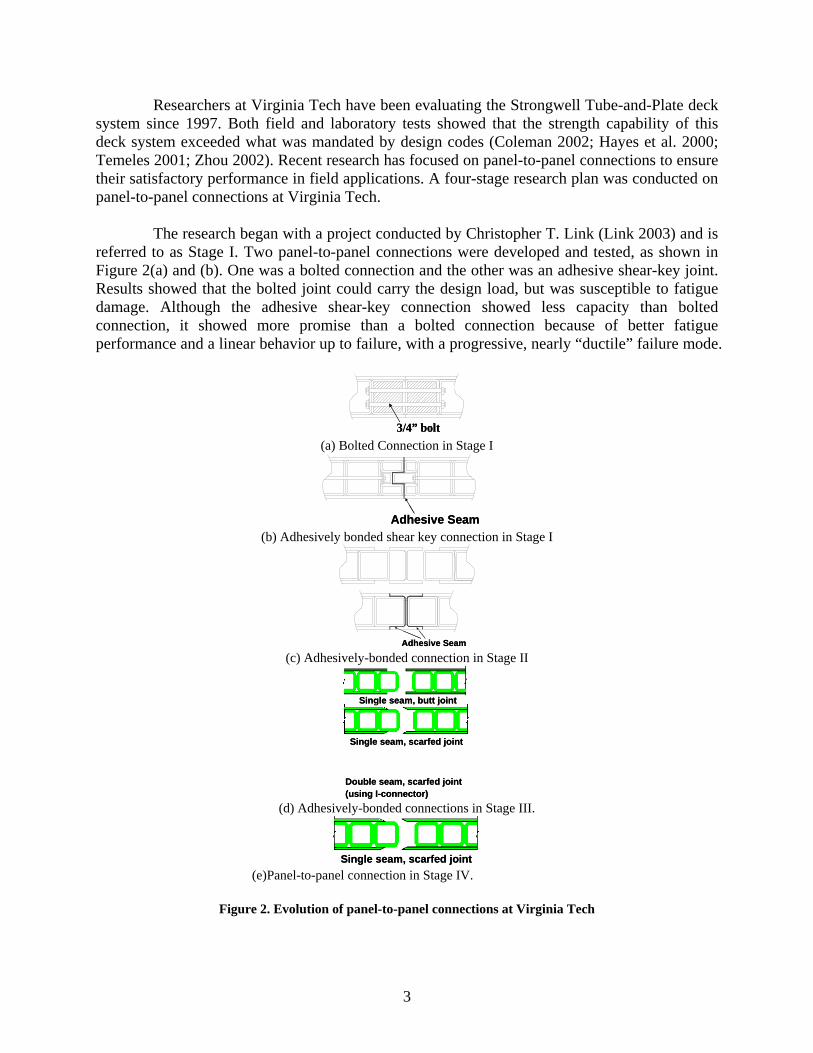
Researchers at Virginia Tech have been evaluating the Strongwell Tube-and-Plate deck system since 1997. Both field and laboratory tests showed that the strength capability of this deck system exceeded what was mandated by design codes (Coleman 2002; Hayes et al. 2000; Temeles 2001; Zhou 2002). Recent research has focused on panel-to-panel connections to ensure their satisfactory performance in field applications. A four-stage research plan was conducted on panel-to-panel connections at Virginia Tech.
The research began with a project conducted by Christopher T. Link (Link 2003) and is
referred to as Stage I. Two panel-to-panel connections were developed and tested, as shown in Figure 2(a) and (b). One was a bolted connection and the other was an adhesive shear-key joint. Results showed that the bolted joint could carry the design load, but was susceptible to fatigue damage. Although the adhesive shear-key connection showed less capacity than bolted connection, it showed more promise than a bolted connection because of better fatigue performance and a linear behavior up to failure, with a progressive, nearly “ductile” failure mode.
3/4” bolt3/4” bolt (a) Bolted Connection in Stage I
Adhesive SeamAdhesive Seam (b) Adhesively bonded shear key connection in Stage I
Adhesive SeamAdhesive Seam (c) Adhesively-bonded connection in Stage II
Single seam, butt joint
Single seam, scarfed joint
Double seam, scarfed joint(using I-connector)
Single seam, butt joint
Single seam, scarfed joint
Double seam, scarfed joint(using I-connector)
(d) Adhesively-bonded connections in Stage III.
Single seam, scarfed jointSingle seam, scarfed joint (e)Panel-to-panel connection in Stage IV.
Figure 2. Evolution of panel-to-panel connections at Virginia Tech

4
The findings from Stage I research showed that although mechanical connections have the advantage of easy disassembly for repair, adhesively-bonded connections are more efficient in shear and moment transfer and fatigue resistance and are easier and cheaper to construct, which was in agreement with published research (Zetterberg et al. 2001). Thus Stages II through IV research focused on developing and evaluating a redesigned adhesively-bonded tongue and groove joint.
In Stage II, a full-length, simplified adhesively-bonded tongue and groove panel-to-
panel connection [Figure 2(c)] was tested in a weak-direction (beam) bending configuration. The testing showed some promising aspects: linear behavior up to failure stage; crack initiation after design service load strain was reached; and a factor of safety of 2.4 with respect to the anticipated service strain. Testing results indicated the adhesive bonding was a viable technique in using with panel-to-panel joint for FRP decks. Stage III research was aimed to further optimize this design.
In Stage III, different connection geometries (scarfed vs. butt joint behavior) were
investigated. The joining effectiveness of simple butt joint geometry was tested as shown in Figure 2(d). Premature cracking was observed in the butt joint area. To eliminate this tendency the joints in Stage III panels were sloped or scarfed, as shown in Figure 2(d). The testing setup and the mimic part of the FRP deck system are shown in Figure 3(a). Test results (Soto J et al. 2004) indicate that FRP samples with a scarfed edge have better performance than those having a butt joint (90°) under a four-point bending configuration, as shown in Figure 3(b). The critical load and displacement (at crack initiation) increased as scarf angle decreased. But for FRP deck panels, sharper scarf angles (smaller than 1/2 slope) are difficult to manufacture and can be easily damaged during transportation and installation. Therefore, scarf joints with an angle of 27° (1/2 slope) were used on the test specimens and recommended for future field application.
(b)
Scarfed angle(a) Scarfed angleScarfed angle(a)(a) Scarfed angle
0
0.5
1
1.5
2
0 15 30 45 60 75 90Scarf Angle (deg)
Cri
tical
Loa
d (k
ips)
0
0.1
0.2
0.3
0.4
Crt
ical
Dis
plac
emen
t(in
)
Critical Load
CrtiticalDisplacement
15°Scarf
Butt joint
(b)
Scarfed angle(a) Scarfed angleScarfed angle(a)(a) Scarfed angleScarfed angle(a) Scarfed angleScarfed angle(a)(a) Scarfed angle
0
0.5
1
1.5
2
0 15 30 45 60 75 90Scarf Angle (deg)
Cri
tical
Loa
d (k
ips)
0
0.1
0.2
0.3
0.4
Crt
ical
Dis
plac
emen
t(in
)
Critical Load
CrtiticalDisplacement
15°Scarf
Butt joint
Figure 3. Critical load and displacement increased as
scarf angle decreased, under 4-point bend test. Two types of adhesively-bonded panel-to-panel connections with scarfed joints were
tested in Stage III: one single seam connection and one double seam connection, as shown in

5
Figure 2(d). A plate bending setup with three sides simply supported and one side free (which approximates the support condition near an abutment) was used to better represent the on-site situation instead of one-way bending setup in Stage II.
Testing indicated that both types of connections exceeded service load without cracking.
Crack initiation in all adhesive joints tested occurred at a load level at least 30% greater than the HL-93 design truck loads as specified in AASHTO LRFD Bridge Design Specifications (2004). It corresponds to a service tire load of 16 kips, with a dynamic load allowance of 33%, which yields a load of 21.3 kips. The observed failure occurred not in the adhesive joints, but was localized in the top plate and tube section at a high load and strain level. Failure loads were at least two times the design service load. No significant advantage or difference in behavior was found using double seam connection (using I-connectors) compared to single seam connection for the deck joints tested. Since the double seam connection involves developing a new, special pultruded shape (I-connector), the single seam connection (Figure 2(e)) was used in the Stage IV study: full-scale two-bay characterizations of the five-bay Hawthorne St. Bridge.
Finally in Stage IV (the subject of this report), a full-scale two-bay section of the bridge
was constructed and tested in the Structures Laboratory at Virginia Tech. Static, fatigue, and failure tests were conducted on the adhesive panel-to-panel connections to evaluate their performances.
PURPOSE AND SCOPE
In order to evaluate the structural behavior and constructability of the proposed panel-
to-panel connection, a 33 ft. by 22 ft. FRP deck supported by a two-bay mock-up of the Hawthorne St. Bridge superstructure was built in the Structures and Materials Laboratory at Virginia Tech. Following construction and testing of the two-bay mock-up the proposed deck system was installed in the Hawthorne St. Bridge. Conclusions and Recommendations resulting from the installation and a subsequent live load test (scheduled to be performed during Spring, 2007) will be reported in an interim report.
The constructability and performance of an adhesively-bonded, panel-to-panel
connection is reported herein. The objectives of this study were four-fold: (1) investigate connection behavior under simulated pseudo-static service load; (2) examine flexural strength and failure mode of connections and deck; (3) explore fatigue behavior during simulated cyclic wheel loading and residual strength after fatigue loading; and (4) develop installation protocol of panel-to-panel connection in Hawthorne St. Bridge.
METHODS
FRP Bridge Deck System The FRP Deck System developed for the Hawthorne St. Bridge was based on previous
research projects conducted at Virginia Tech, and was fabricated from standard EXTREN® structural shapes and plate manufactured by Strongwell Corp. of Bristol, VA. These components

6
are made of E-glass roving and continuous strand mat embedded in polyester resin. The typical cross section of a deck panel is shown in Figure 4. The off-the-shelf components include: 6 in. x 6 in. x 3/8 in. pultruded EXTREN® tubes, 3/8 in. pultruded EXTREN® top and bottom plates as well as 1 in. diameter steel thru-rods. The tubes, top and bottom plate are adhesively bonded to form FRP bridge deck panels. The steel thru-rods are used to provide necessary binding forces when the deck panels are in curing. Bonding is accomplished in a vacuum bag to produce uniform pressure and continuous bonding.
3/8” pultruded top plate
3/8” pultruded bottom plate
1” diameter steel thru-rods
6” x 6” x 3/8” pultruded tubes
3/8” pultruded top plate
3/8” pultruded bottom plate
1” diameter steel thru-rods
6” x 6” x 3/8” pultruded tubes
Figure 4 . Cross section of the Strongwell FRP Deck System
The material properties of Strongwell’s deck components are listed in Table 1 (tube and
plates). The given material properties are taking from Extren Design Manual (Strongwell Inc. 2002), which are minimum ultimate coupon properties.
Table 1. Material Properties of Strongwell’s Deck Components
Mechanical Properties Top/Bottom Plate
Tube
Ultimate flexural stress, LW1 (ksi) 30 30 Ultimate flexural stress, CW2 (ksi) 18 10 Flexural modulus of elasticity, LW1
(ksi)
2000 1595
Flexural modulus of elasticity, CW2
(ksi) 1400 800
Estimated ultimate strain3, LW1 (με)
15000 18800
Estimated ultimate strain3, CW2 (με)
12800 12500
1: LW – lengthwise (longitudinal); 2 CW – crosswise (transverse); 3: Ultimate strain approximated by dividing the ultimate stress by the corresponding elastic moduli
Figure 5 shows a plan view of deck panels, panel-to-panel connections, and supporting
steel superstructure. The FRP deck specimen consisted of five individual modular deck panels that were jointed together using three adhesive panel-to-panel connections (Seam #1 through #3) and one dowel joint. The dowel joint was developed as an expansion joint for future applications, and will not be discussed here. Each individual panel was 22 by 7.5 ft., with the exception of the two end panels which measured 22 by 5.5 ft., and 22 by 5 ft. These individual panels were connected to form a full width 22 ft. panel that was about 33 ft. long in the direction of traffic.

7
Figure 5 . FRP deck panels and joints of the Hawthorne St. Bridge mock-up. The FRP deck specimen was connected to stringers by deck-to-stringer connections;
these connections were not intended to develop composite action. Neoprene rubber pads (1/4 in. thickness) were used to cover all contact areas between the deck panels and the steel superstructures.
Construction of Adhesively-Bonded Panel-to-Panel Connections The accuracy of panel dimensions of the mating parts has a significant impact on the
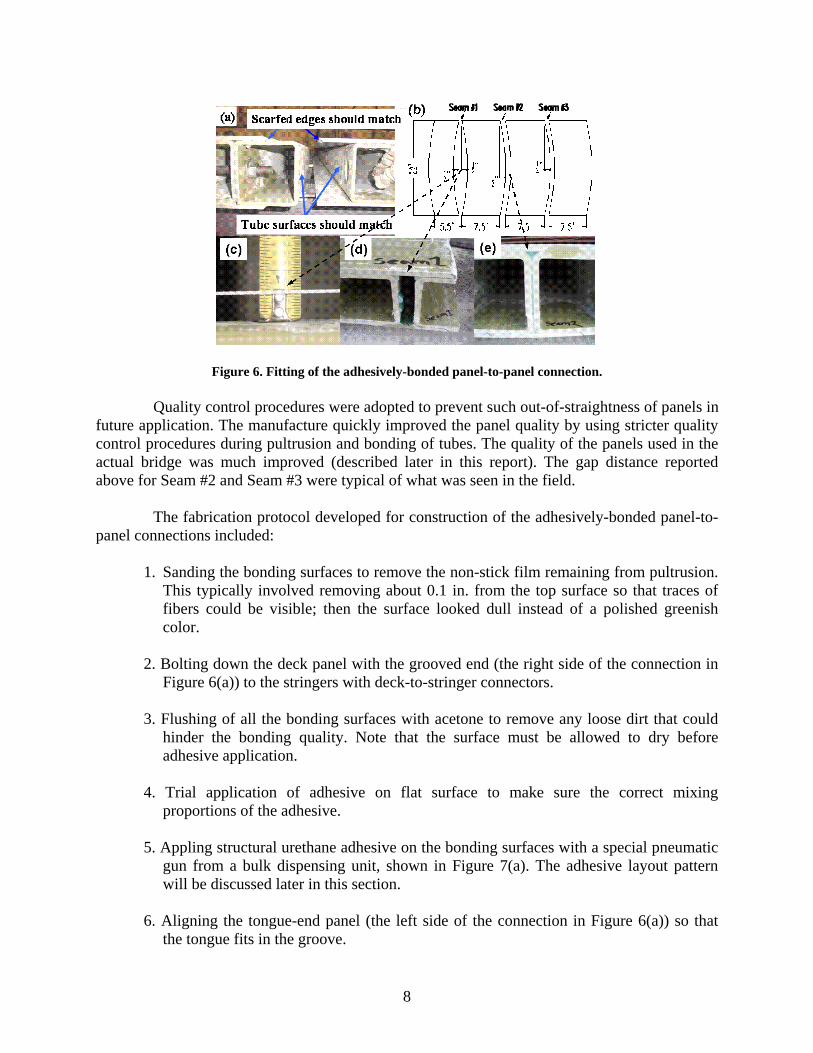
ease of installation and quality of the adhesive panel-to-panel connections. Therefore, the first step was to dry-fit every panel-to-panel connection to ensure the best fit. Specifically, the scarfed edges should match and side walls of the tube bonding surface should match as well (Figure 6(a)). The gap distance between two bonding surfaces should be controlled to less than 0.1 in. to ensure adhesive can fill the entire gap without voids.
During dry-fitting of three panel-to-panel connections, it was found that the sweep of
the tubes was not well controlled during pultrusion. Figure 6(b) shows the curved panels resulting from the use of curved tubes. Each panel had a pre-existent sweep with a midway deflection about 0.5 in. Figure 6(c)). The worst case was Seam #1 with two opposite curvatures at the side walls of the tube bonding surface. Although Seam #2 and #3 also had similar curvatures, mating tubes were bent in the same direction. The deck panels were autopsied after testing was completed to further investigate the bonding quality. Figure 6(d) shows that the gap distance between two bonding tube surfaces of Seam #1 was about 1 in. The gap distances of Seam #2 and #3 were less than 0.1 in. and all scarfed edges matched well. Figure 6(e) shows the bonding quality of Seam #2.
8
Figure 6. Fitting of the adhesively-bonded panel-to-panel connection. Quality control procedures were adopted to prevent such out-of-straightness of panels in
future application. The manufacture quickly improved the panel quality by using stricter quality control procedures during pultrusion and bonding of tubes. The quality of the panels used in the actual bridge was much improved (described later in this report). The gap distance reported above for Seam #2 and Seam #3 were typical of what was seen in the field.
The fabrication protocol developed for construction of the adhesively-bonded panel-to-
panel connections included:
1. Sanding the bonding surfaces to remove the non-stick film remaining from pultrusion. This typically involved removing about 0.1 in. from the top surface so that traces of fibers could be visible; then the surface looked dull instead of a polished greenish color.
2. Bolting down the deck panel with the grooved end (the right side of the connection in
Figure 6(a)) to the stringers with deck-to-stringer connectors.
3. Flushing of all the bonding surfaces with acetone to remove any loose dirt that could hinder the bonding quality. Note that the surface must be allowed to dry before adhesive application.
4. Trial application of adhesive on flat surface to make sure the correct mixing
proportions of the adhesive. 5. Appling structural urethane adhesive on the bonding surfaces with a special pneumatic
gun from a bulk dispensing unit, shown in Figure 7(a). The adhesive layout pattern will be discussed later in this section.
6. Aligning the tongue-end panel (the left side of the connection in Figure 6(a)) so that
the tongue fits in the groove.

9
7. Joining deck panels by equal jacking pressure from six hydraulic jacks with a manifold system, shown in Figure 7(b). Enough pressure must be applied to close the joint and ensure that adequate adhesive squeezes out.
8. Maintaining the jack pressure for about 12 hours, until the adhesive cured. 9. Bolting down the deck panel to the stringers with deck-to-stringer connectors. 10. Going through steps (3) through (9) for another adhesive connection.
(a) Adhesive application (b) Jacking system
Figure 7. Adhesive construction for panel-to-panel connection. The performance of adhesive bonding is not only dependent on the matching condition
of mating parts, surface preparation, and joint geometry as discussed above, but also the amount of adhesive applied. Adequate adhesive squeeze out is a sign that adequate adhesive was applied and is recommended as the quality control check-point in field construction. Increasing amounts of adhesive was applied to the three seams in order to compare performances of seams with different amounts of adhesive (Seam #3 had the most and Seam #1 had the least). Seam #3 was thought to be the best joint with the best fit and sufficient adhesive squeeze out. Figure 8 shows Seam #3 after adhesive was applied and adequate adhesive squeezed out from the top, side and bottom of the joint. Although Seams #1 and #2 performed well during static tests (discussed in a later section), the amount of adhesive used for Seam #3 was selected as enough to ensure adequate strength and life of the panel-to-panel connection.

10
(a) Side view (b) Bottom view
Figure 8. Adhesive squeezing out from joints during adhesive construction. The Pliogrip 8000/6660 two-component, structural urethane adhesive system from
Ashland Chemicals Inc. was used in this application for its superior adhesion property, UV resistance and proper glass transition temperature. Figure 9 shows how the adhesive beads were applied on the tongue and groove parts. Each bead had a width of about 0.4-0.6 in. and a thickness of about 1/4-1/2 in. One bead of adhesive was applied on each scarfed edges. The amount of adhesive applied per connection was about 14.2 Liters of Pliogrip 8000 and 6.3 Liters of Pliogrip 6660.
(a) Adhesive on tongue part (b) Adhesive on groove part
Figure 9. Adhesive layout pattern. The available working time for the adhesive is 45 minutes at 73°F and 35 minutes at
99°F. Application of adhesive and joining of deck panels took approximately 25 minutes and was performed at an ambient temperature of 75°F.

11
TEST SETUP AND INSTRUMENTATION
Test Setup The steel frame mock-up of the Hawthorne St. Bridge superstructure consisted of two
bays, which were 16 ft. and 15 ft. in length in the direction of traffic. Figure 10 shows a framing plan of the steel superstructure. Each bay had six wide-flange W14x34 stringers, having a transverse spacing of 4 ft. on-center. Diaphragm members, consisting of C10x15.3 steel sections, were bolted to connector plates, which were in turn welded to the stringers. Two W14x120 floor beams were supported by four pedestals that simulated the hangers in the through-truss bridge. All steel member sizes and dimensions mimic the actual ones in the Hawthorne St. Bridge superstructure. Neoprene pads were used between floor beams and pedestals to avoid direct contact of steel and to allow some movement at floor beam ends. Stringers and floor beams were jointed together using moment resisting connections. A W21x132 beam was used to simulate the concrete abutment in situ, and five end diaphragms (C10x30) were flush with the top stringer to avoid free edge effect of the FRP deck. All stringers at the abutment rested on the bearings anchored on the abutment.
Although the rehabilitated bridge will still be posted to 20 tons, a higher load level (HL-93 design truck loads as specified in AASHTO LRFD Bridge Design Specifications) was used for evaluating the performance of the adhesive panel-to-panel connections. The purpose was to gain some insight into the applicability of this deck system to the typical highway bridge deck which is designed for the HL-93 design truck. This yields a service tire load of 16 kips with a dynamic load allowance of 33%, which yields a load of 21.3 kips. Therefore, a load limit of 22 kips was chosen because it was slightly higher than the required 21.3 kips.
C10x15.3 Diaphragms
Floor beam #1 Floor beam #2Abutment
15’ 16’
Moment Resisting
(W14x120) (W14x120)
5x4’
Stringer #1
Stringer #2
Stringer #3
Stringer #4
Stringer #5
Stringer #6
W14x34 Stringers
2’
24’
2’
Connections
C10x15.3 Diaphragms
Floor beam #1 Floor beam #2Abutment
15’ 16’
Moment Resisting
(W14x120) (W14x120)
5x4’
Stringer #1
Stringer #2
Stringer #3
Stringer #4
Stringer #5
Stringer #6
W14x34 Stringers
2’
24’
2’
Connections
Figure 10. Framing plan of the steel superstructure of the Hawthorne St. Bridge mock-up.
Five Load Cases used for service load tests are shown in Figure 11. All Load Cases followed HL-93 truck weights and dimensions to apply the worst-case load scenario to the FRP deck and superstructure. Load Cases 1–4 were single truck cases. Load Cases 1, 2 and 4 were the
12
critical cases for flexure of an FRP deck transverse to the traffic, with a wheel located at mid-span between two stringers. Load Case 3 represented a truck straddling on Stringer 3. Load Case 5 is the symmetric case, with double trucks representing the full lane Load Case.
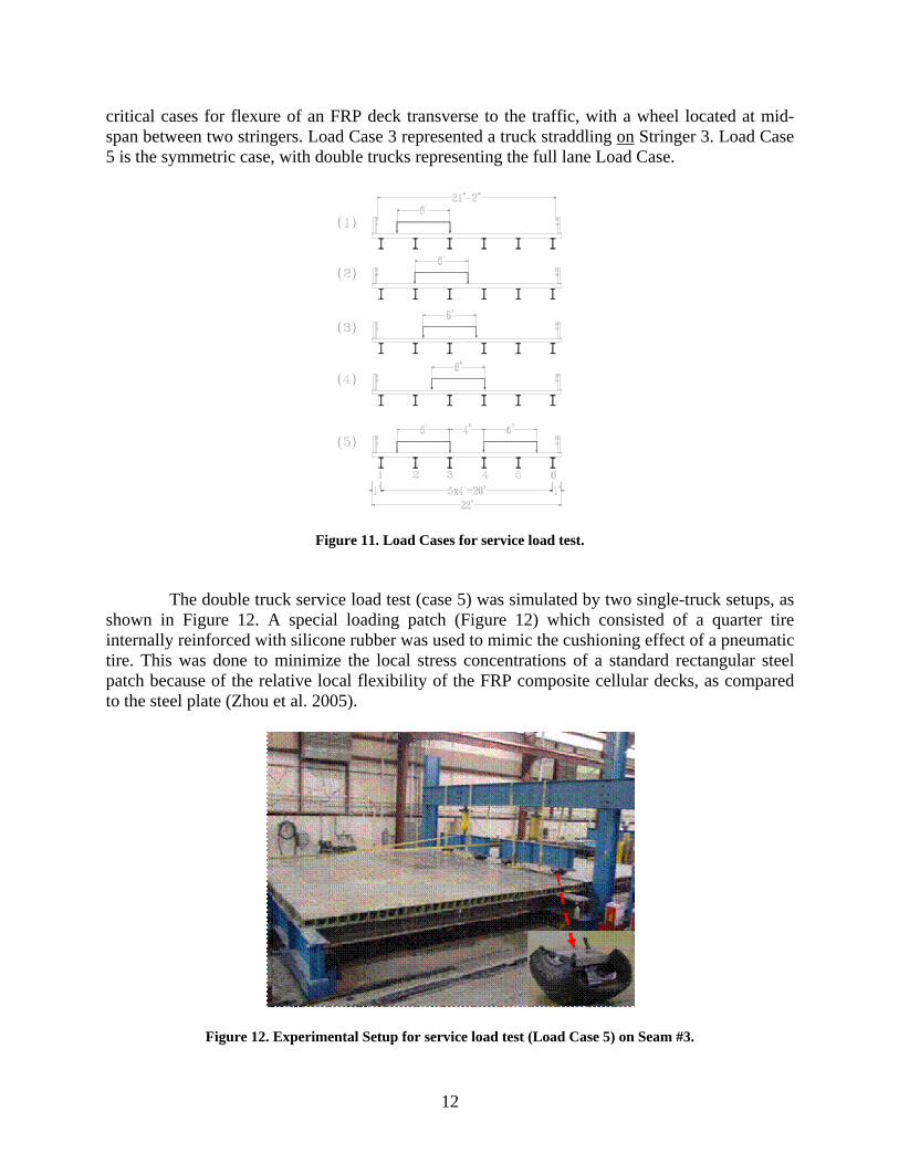
Figure 11. Load Cases for service load test. The double truck service load test (case 5) was simulated by two single-truck setups, as
shown in Figure 12. A special loading patch (Figure 12) which consisted of a quarter tire internally reinforced with silicone rubber was used to mimic the cushioning effect of a pneumatic tire. This was done to minimize the local stress concentrations of a standard rectangular steel patch because of the relative local flexibility of the FRP composite cellular decks, as compared to the steel plate (Zhou et al. 2005).
Figure 12. Experimental Setup for service load test (Load Case 5) on Seam #3.

13
In the strength tests, the same hydraulic actuator and tire patch pair was used to apply load to the deck directly between two adjacent stringers, to simulate one wheel load. A number of steel plates were inserted in between the loading ram and the tire patches to ensure a nearly uniform distribution of load from the actuator to the two tire patches. For fatigue tests, load was applied using a servo-controlled hydraulic actuator mounted on the same load frame. Because of concern about stability of the actuator and load patch assembly, a neoprene rubber patch was used instead of tire patch to transfer load from the actuator to the top surface of the deck on top of the adhesive joint. The neoprene rubber pad can also prevent the steel plate connected to the actuator from locally damaging the deck and joint during testing. The base neoprene rubber pad was 18 in. by 9 in. and. The base neoprene rubber pad is a little smaller than the “tire contact area” of 20 in. by 10 in. defined in AASHTO LRFD Specifications (2004).
Instrumentation The schematic of the instrumentation plan used to investigate the performance of
adhesively-bonded joints is shown in Figure 13. The stringers and floor-beams are referred to as “Stringer #1” through “Stringer #6” and “Floor Beam #1” and “Floor Beam #2.” For consistency throughout the discussion, all references to “longitudinal” and “transverse” are given with respect to the bridge deck orientation; thus, “longitudinal” implies parallel to the pultruded tube direction of the FRP deck system, and the “transverse” direction refers to the traffic flow direction (perpendicular to the tube axis).
As shown in Figure 14, at the bottom surface of the deck, two strain gauges and two
wire pots (displacement transducers) were used to measure transverse strains and displacements, respectively, at both sides of the joint. Another strain gauge was placed to measure longitudinal strain at the side of the adhesive joint adjacent to the load. A specially-designed crack detection gauge [shown in Figure 13] was installed across each joint to monitor crack opening, if any. This instrumentation pattern was repeated for each loading location while testing near a joint. Load, deflection, and strain were continuously recorded during testing using a high-speed data acquisition system.
Figure 13. Instrumentations for three adhesively-bonded panel-to-panel connections (underneath the deck).

14
RESULTS AND DISCUSSIONS
Service Load Test The purpose of these tests was to observe the behavior and assess the serviceability and
performance of the adhesively-bonded, panel-to-panel joint up to a wheel load of 22 kips (a 44 kips axle load).
The representative span deflection and crack gauge responses at one location, location
RPL (shown in Figure 13) under Load Case 4 are shown in Figure 14. The load vs. strain and load vs. deflection behaviors were observed to be fairly linear elastic up to the design service load. The absolute deflection at the mid-span of the deck was 0.335 in., as shown in Figure 14(a), and the relative deflection at this point with respect to supporting stringers was 0.074 in. at the design service load, which indicated an L/649 response.
At location RPL under Load Case 4, the longitudinal strain on the bottom plate right
under the load patch was 1090 με, which is only 6% of the estimated ultimate strain of the bottom plate. Transverse strain at one side of the seam close to the loading patch was 490 με at the design service load, which was about 45% of the longitudinal strain at this load. However, transverse strain at the other side of the seam was -290 με at the design service load, which was in compression; this indicated that this region experienced double curvature due to an applied load at one side of the seam. The linear response of crack gauge indicates that no crack was initiated up to design service load, as shown in Figure 14(b).
0
10
20
30
40
50
0 0.1 0.2 0.3 0.4Deflection (in.)
Load
(kip
s)
0
10
20
30
40
50
0 0.002 0.004 0.006 0.008Crack gauge reading (in.)
Load
(kip
s)
(a) Load vs. deck overall deflection (b) Load vs. crack gauge reading Figure 14. Representative plots in service load tests
For all loading cases, deflection and longitudinal strain were reasonably consistent. This
consistency of measured responses from both continuous deck sections and adhesive joints indicated effective performance of the adhesively-bonded, panel-to-panel connections. However, transverse strains were found to be very sensitive to the exact location of both the gauge and the applied loads, and more difficult to interpret. This agreed with published findings (Coogler et al. 2005; Turner et al. 2004; Wan et al. 2005). Due to their variability, such measurements are less suitable for performance assessment and will not be used in strength and fatigue performance evaluation.
15
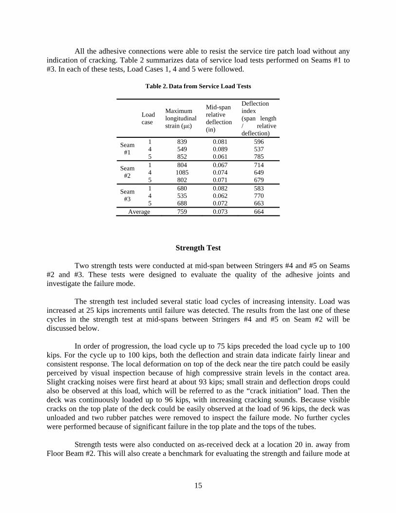
All the adhesive connections were able to resist the service tire patch load without any indication of cracking. Table 2 summarizes data of service load tests performed on Seams #1 to #3. In each of these tests, Load Cases 1, 4 and 5 were followed.
Table 2. Data from Service Load Tests
Load case
Maximum longitudinal strain (με)
Mid-span relative deflection (in)
Deflection index (span length / relative deflection)
1 839 0.081 596 4 549 0.089 537 Seam
#1 5 852 0.061 785 1 804 0.067 714 4 1085 0.074 649 Seam
#2 5 802 0.071 679 1 680 0.082 583 4 535 0.062 770 Seam
#3 5 688 0.072 663 Average 759 0.073 664
Strength Test Two strength tests were conducted at mid-span between Stringers #4 and #5 on Seams
#2 and #3. These tests were designed to evaluate the quality of the adhesive joints and investigate the failure mode.
The strength test included several static load cycles of increasing intensity. Load was
increased at 25 kips increments until failure was detected. The results from the last one of these cycles in the strength test at mid-spans between Stringers #4 and #5 on Seam #2 will be discussed below.
In order of progression, the load cycle up to 75 kips preceded the load cycle up to 100
kips. For the cycle up to 100 kips, both the deflection and strain data indicate fairly linear and consistent response. The local deformation on top of the deck near the tire patch could be easily perceived by visual inspection because of high compressive strain levels in the contact area. Slight cracking noises were first heard at about 93 kips; small strain and deflection drops could also be observed at this load, which will be referred to as the “crack initiation” load. Then the deck was continuously loaded up to 96 kips, with increasing cracking sounds. Because visible cracks on the top plate of the deck could be easily observed at the load of 96 kips, the deck was unloaded and two rubber patches were removed to inspect the failure mode. No further cycles were performed because of significant failure in the top plate and the tops of the tubes.
Strength tests were also conducted on as-received deck at a location 20 in. away from
Floor Beam #2. This will also create a benchmark for evaluating the strength and failure mode at
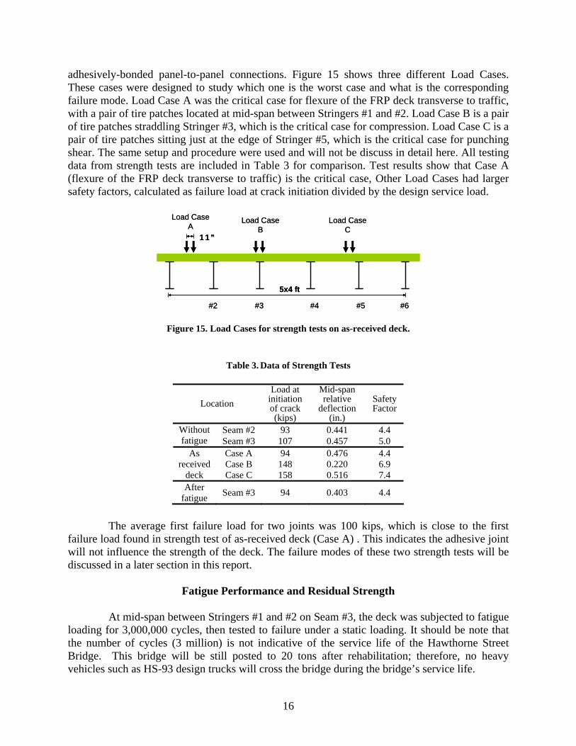
16
adhesively-bonded panel-to-panel connections. Figure 15 shows three different Load Cases. These cases were designed to study which one is the worst case and what is the corresponding failure mode. Load Case A was the critical case for flexure of the FRP deck transverse to traffic, with a pair of tire patches located at mid-span between Stringers #1 and #2. Load Case B is a pair of tire patches straddling Stringer #3, which is the critical case for compression. Load Case C is a pair of tire patches sitting just at the edge of Stringer #5, which is the critical case for punching shear. The same setup and procedure were used and will not be discuss in detail here. All testing data from strength tests are included in Table 3 for comparison. Test results show that Case A (flexure of the FRP deck transverse to traffic) is the critical case, Other Load Cases had larger safety factors, calculated as failure load at crack initiation divided by the design service load.
5x4 ft
11”
Load Case A
#2 #3 #4 #5 #6
Load Case B
Load Case C
5x4 ft
11”
Load Case A
#2 #3 #4 #5 #6
Load Case B
Load Case C
Figure 15. Load Cases for strength tests on as-received deck.
Table 3. Data of Strength Tests
Location Load at
initiation of crack (kips)
Mid-span relative
deflection (in.)
Safety Factor
Seam #2 93 0.441 4.4 Without fatigue Seam #3 107 0.457 5.0
Case A 94 0.476 4.4 Case B 148 0.220 6.9
As received
deck Case C 158 0.516 7.4 After
fatigue Seam #3 94 0.403 4.4
The average first failure load for two joints was 100 kips, which is close to the first failure load found in strength test of as-received deck (Case A) . This indicates the adhesive joint will not influence the strength of the deck. The failure modes of these two strength tests will be discussed in a later section in this report.
Fatigue Performance and Residual Strength At mid-span between Stringers #1 and #2 on Seam #3, the deck was subjected to fatigue
loading for 3,000,000 cycles, then tested to failure under a static loading. It should be note that the number of cycles (3 million) is not indicative of the service life of the Hawthorne Street Bridge. This bridge will be still posted to 20 tons after rehabilitation; therefore, no heavy vehicles such as HS-93 design trucks will cross the bridge during the bridge’s service life.

17
The fatigue test was conducted in load control at a minimum/maximum load ratio of R=0.1, with a maximum load of 22 kips and a minimum load of 2 kips. The deck cycled through a maximum deflection range of about.19 in. at the load point and through a maximum bottom plate longitudinal strain (along the tube direction) of about 600 με underneath the loading patch. The fatigue cycles were interrupted periodically for static service load tests, and the deck panel was inspected for signs of deterioration at this time as well.
The maximum deflection and strain measurements at the service load (22 kips) taken
during each static test can be seen in Figure 16(a) and (b), respectively. The deflection and strain responses remained fairly constant for all of the static service load tests, and the deck demonstrated no apparent loss in stiffness near the adhesive joint. The crack gauge measurements taken during the static test after 3,000,000 cycles show linearly response indicating no crack was initiated after 3,000,000 cycles. Similar deflection measurements at two sides of the adhesive joints during the static test after 3,000,000 cycles also demonstrated that no crack was initiated inside the joint.
0
200
400
600
800
1000
0.E+00 1.E+06 2.E+06 3.E+06
No of cycle
Mic
rost
rain
0
0.1
0.2
0.3
0.0E+00 1.0E+06 2.0E+06 3.0E+06
No of cycle
Dis
plac
emen
t (in
.)
(a) Strain (b) Deflection
Figure 16. Maximum strain and deflection at service load after interrupted fatigue loading.
Inspection of the deck at the time of each static service load test also revealed no visible
signs of damage to the plate or adhesive bonding due to fatigue loading. In addition, a careful inspection the area of deck-to-stringer connections near loading patch was conducted after 3,000,000 cycles, and no damage to the deck panel and no slack in the connection were observed.
The fatigue test was followed by a residual strength test at the same location. Figure
17(a) shows the load versus deflection plot and Figure 17 (b) shows the load versus crack gauge plot. Both responses showed fairly linear-elastic behavior up to the crack initiation of the adhesive joint after 3,000,000 fatigue cycles. The first failure (crack initiation in the joint) occurred at 94 kips. At the crack initiation point, both plots showed a significant drop due to stiffness loss caused by cracking in the adhesive joint. Figure 17(b) also shows a clear crack propagation stage after crack initiation. The critical loads at initiation of crack after fatigue and without fatigue shown in Table 3 indicate no significant loss in strength after fatigue.

18
The residual strength mode of failure observed on the fatigued seam is typical of those observed in the two strength tests discussed above. This observation, when combined with the observed retention of stiffness after fatigue loading, demonstrates the good durability of the adhesive joint under repetitive loadings.
020406080
100120
0 0.4 0.8 1.2Displacement (in.)
Load
(kip
s)
Crackinitiationat about94 kips
0
30
60
90
120
150
0 0.01 0.02 0.03 0.04 0.05
Crack gage deflection (in.)
Load
(kip
s)
Crack propagation
Crack initiation
(a) Load versus deflection (b) Load versus crack gauge reading
Figure 17. Crack gauge and deck deflection results from residual strength test after 3,000,000 cycles
Failure Modes The failure mode observed on the seam that was fatigued to 3,000,000 cycles and then
tested to failure is very consistent with that observed on two adhesive seams tested to failure without being fatigued. For all seams in the ultimate test, the failure areas were highly localized and right under the tire patches, as seen in Figure 18(a). Failure mode was flexural failure of the top plate and top flange of the tube. Three cracks could be seen (Figure 18(b)). Two cracks developed along two webs of the tube under the loading tire patch, and one crack was at about the center of the 6 in. span between two webs of the tube. Figure 18(c) shows a side view of the top surface flexural failure; no crack was observed on the tube webs. Also, no visible crack was observed at the bottom side of the deck near the adhesive joint after the top surface failed. From these results, it was concluded that the top plate and the top flange of the tube failed in weak-axis bending, with cracking parallel to the tube webs.
Another important observation from Figure 18(b) is that although the fracture at mid-
span of two webs of the tube was near the adhesively-bonded line, no failure was observed in the adhesive layer or in the joint interface. This suggests the adhesive layer and adhesive-substrate interface are stronger than the FRP components and that adhesive bonding is a viable technique for the panel-to-panel connections in FRP bridge deck system. In addition, the tests demonstrated ductile failure rather than a total collapse, which would provide plenty of time for evacuation and maybe considered as another advantage of this FRP deck system.

19
Figure 18. Failure mode in strength test (a) Highly localized surface failure (b) Failure detail on top surface of
the deck (c) Side view of the flexural failure of top surface.
BRIDGE INSTALLATION
The FRP bridge deck installation was started at the Hawthorne St. Bridge on August
29th, 2006. Figure 19 shows the adhesive bonding process of the panel-to-panel connections during deck installation. The accuracy of panel dimensions of the mating parts was well controlled and installation protocols were strictly followed during the field installation. The bridge is scheduled for a controlled live load test and the response of the adhesively bonded panel-to-panel connection will be monitored.
(a) (b)
(c) (d)
(a) (b)
(c) (d)
Figure 19. Field installation of the FRP bridge deck (a) Dry fit (b) Adhesive application (c) Seam curing (d)
Jacking system
20
SUMMARY OF FINDINGS
1. All the adhesive joints were able to resist the design service load without any indication of cracking.
2. The strain and displacement showed linear elastic behavior up to design service load. The test
results revealed an average deflection of span/664, which is slightly larger than the span/800 criteria in the AASHTO LRFD Bridge Design Specifications (2004). It should be noted that this limit is not intended for application to FRP composite bridge decks. However, no appropriate design limit is presently available.
3. The proposed full-length, adhesively-bonded tongue and groove panel-to-panel joints can
meet the necessary strength performance criteria. No failure was observed in the adhesive layer or in the joint interface, which indicates the adhesive layer and adhesive-substrate interface are stronger than the FRP components. Thus adhesive bonding will not control the design strength of this FRP deck system.
4. The average first failure load was 100 kips in the strength tests on the adhesive joints, about
five times the design service load of 22 kips. This value is close to the first failure load found in strength tests of as-received decks and indicates the adhesive joint will not influence the strength of the deck.
5. The failure in the top plate and the top flange of the tube was caused by weak-axis bending,
with cracking parallel to the tube webs. This is also consistent with the failure mode in strength tests of as-received decks.
6. No significant change in stiffness or strength of the deck after 3,000,000 cycles of a fatigue
load at a minimum/maximum load ratio of R=0.1, with the maximum load of 22 kips and the minimum load of 2 kips. This demonstrated the durability of the adhesive joint under repetitive loading.
CONCLUSIONS
• The Strongwell FRP bridge deck system is a lightweight and safe alternative to conventional reinforced concrete bridge decks.
• The full scale model of two bays of the five-bay Hawthorne St Bridge provided valuable
insights into the constructability of the adhesive panel-to-panel connections. The resulting field joint fabrication protocol was developed and used during fabrication of the deck joints in the field. The fabrication of the actual deck joints went smoothly and therefore validates the use of the developed protocol on other FRP deck installations.
• Based on the test results obtained during the laboratory testing of the two-bay model, it was
concluded that this adhesive bonding technique has the necessary serviceability and strength characteristics to be used in other similar bridge deck replacements. The testing program addressed the performance of the proposed bridge deck system under repeated (cyclic) loads.

21
No discernable loss in strength or stiffness was observed. However, since the testing only subjected the deck to one source of degradation (repeated loads), future research should focus on the performance of the Strongwell FRP deck system when subjected to varying moisture and temperature environments.
RECOMMENDATIONS 1. Based on the results of the laboratory study, VDOT’s Structure & Bridge Division and
VDOT’s Staunton District should proceed with the rehabilitation of the Hawthorne Street Bridge using the FRP bridge deck system tested in this study.
2. VDOT’s Structure & Bridge Division should consider using the FRP bridge deck system on
other appropriate bridge candidates.
COSTS AND BENEFITS ASSESSMENT
The Hawthorne Street Bridge in Covington, Virginia, spans 75 ft and three railroad tracks. The bridge is the first to use the Strongwell FRP bridge deck system in a vehicular bridge superstructure. The findings of this report show that the Strongwell FRP bridge deck system is a lightweight and safe alternative to conventional reinforced concrete bridge decks. One disadvantage regarding the use of this bridge deck system is its cost. The cost per square foot of the Strongwell bridge deck system is significantly greater than a conventional reinforced concrete bridge deck of similar strength and stiffness. The best uses of the Strongwell bridge deck system are ones where the weight savings offset the higher initial material costs.
REFERENCES
American Association of State Highway and Transportation Officials (AASHTO). (2004). AASHTO LRFD bridge design specifications, American Association of State Highway and Transportation Officials, Washington, D.C.
Coleman, J. T. (2002). Continuation of Field and Laboratory Tests of a Proposed Bridge Deck
Panel Fabricated from Pultruded Fiber-Reinforced Polymer Components, M.S. Thesis, Virginia Polytechnic Institute and State University, Blacksburg,VA.
Composite Growth Initiative of the American Composites Manufacturers Association (ACMA).
(2004). Global FRP Use for Bridge Applications: statistics. <http://www.mdacomposites.org> (Sep, 7, 2006).
22
Coogler, K., Harries, K. A., Wan, B., Rizos, D. C., and Petrou, M. F. (2005). Critical Evaluation of Strain Measurements in Glass Fiber-Reinforced Polymer Bridge Decks. J. Bridge Eng, 10(6), 704–712.
Hayes, M. D., Ohanehi, D., Lesko, J. J., Cousins, T. E., and Witcher, D. (2000). Performance of
tube and plate fiberglass composite bridge deck. J. Compos. Constr., 4(2), 48–55. Link, C. T. (2003). Development of Panel-to-Panel Connection for use with a Pultruded Fiber-
Reinforced-Polymer Bridge Deck System, M.E.Report, Virginia Polytechnic Institute and State University, Blacksburg, Virginia.
Moses, J., Harries, K., Earls, C., and Yulismana, W. (2006). Evaluation of Effective Width and
Distribution Factors for GFRP Bridge Deck Supported on Steel Girders. J. Bridge Eng., 11(4), 401-409.
Soto J, Lesko, J., Case, S., Majumdar, P., and Liu, Z. (2004). Design and Testing of Adhesively
Bonded FRP Deck Joints. National Science Foundation (NSF) and Research Experience for Undergraduates (REU) Summer Undergraduate Research Program (SURP),Department of Engineering Science and Mechanics, Virginia Polytechnic Institute and State University, Blacksburg, VA 24061.
Strongwell Inc. (2002). Extren Design Manual, Bristol, VA. Temeles, A. B. (2001). Field and Laboratory Tests of a Proposed Bridge Deck Panel Fabricated
from Pultruded Fiber-Reinforced Polymer Components, M.S. Thesis, Virginia Polytechnic Institute and State University, Blacksburg, Virginia.
Transportation Research Board. (2006). National coooperative Highway Research Program
(NCHRP) Report 564: Field Inspection of In-Service FRP Bridge Decks. Transportation Research Board, Washington, D.C.
Turner, M. K., Harries, K. A., Petrou, M. F., and Rizos, D. (2004). In situ structural evaluation of
a GFRP bridge deck system. Composite Structures, 65(2), 157-165. Wan, B. L., Rizos, D. C., Petrou, M. F., and Harries, K. A. (2005). Computer simulations and
parametric studies of GFRP bridge deck systems. Composite Structures, 69(1), 103-115. Zetterberg, T., Astrom, B. T., Backlund, J., and Burman, M. (2001). On design of joints between
composite profiles for bridge deck applications. Compos. Struc., 51, 83–91. Zhou, A. (2002). Stiffness and strength of fiber reinforced polymer composite bridge deck
systems, Doctoral Dissertation, Virginia Polytechnic Institute and State University, Blacksburg, Virginia.
Zhou, A., and Keller, T. (2005). Joining techniques for fiber reinforced polymer composite
bridge deck systems. Composite Structures, 69(3), 336-345.

23
Zhou, A. X., Coleman, J. T., Temeles, A. B., Lesko, J. J., and Cousins, T. E. (2005). Laboratory and field performance of cellular fiber-reinforced polymer composite bridge deck systems. Journal of Composites for Construction, 9(5), 458-467.