Rittal RiLine60 busbar systems 800 A (60 mm) · 2009-12-28 · System components (3-pole) Rittal...
37
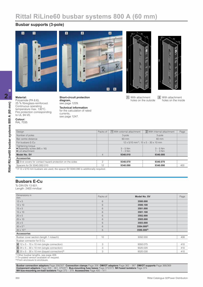
Rittal RiLine60 busbar systems 800 A (60 mm) Busbar supports (3-pole) 350 Rittal Catalogue 32/Power Distribution B 2.2 Rittal RiLine60 busbar systems 800 A (60 mm) 1 3 2 3 5 6 4 Material: Polyamide (PA 6.6), 25 % fibreglass-reinforced. Continuous operating temperature max. 130°C. Fire protection corresponding to UL 94-V0. Colour: RAL 7035 Short-circuit protection diagram, see page 1229. Technical information for the calculation of rated currents, see page 1247. Design Packs of With external attachment With internal attachment Page Number of poles 3-pole 3-pole Bar centre distance 60 mm 60 mm For busbars E-Cu 12 x 5/10 mm 1) , 15 x 5 – 30 x 10 mm Tightening torque ● Assembly screw (M5 x 16) ● Lid attachment 3 – 5 Nm 1 – 3 Nm 3 – 5 Nm 1 – 3 Nm Model No. SV 4 9340.010 9340.000 Accessories End covers for contact hazard protection on the sides 2 9340.070 9340.070 Spacers for SV 9340.000/.010 12 9340.090 9340.090 400 1) If 12 x 5/10 mm busbars are used, the spacer SV 9340.090 is additionally required. 1 2 3 Busbars E-Cu To DIN EN 13 601. Length: 2400 mm/bar. Dimensions in mm Packs of Model No. SV Page 12 x 5 6 3580.000 12 x 10 6 3580.100 15 x 5 6 3581.000 15 x 10 6 3581.100 20 x 5 6 3582.000 20 x 10 6 3585.000 25 x 5 6 3583.000 30 x 5 1) 6 3584.000 2) 30 x 10 1) 6 3586.000 2) Accessories Busbar cover section (length 1 m/each) 10 3092.000 408 Busbar connector for E-Cu 12 x 5 – 15 x 10 mm (single connection) 3 9350.075 410 20 x 5 – 30 x 10 mm (single connection) 3 9320.020 410 20 x 5 – 30 x 10 mm (bayed connection) 3) 3 9320.030 410 1) Other busbar lengths, see page 409. 2) Tin-plated version available on request. 3) From enclosure to enclosure. 4 5 6 Busbar connection adaptors Page 356/357 Connection clamps Page 358 OM/OT adaptors Page 362 – 367 OM/OT supports Page 368/369 Component adaptors Page 359 – 361, 370/371 Bus-mounting fuse bases Page 372/373 NH fused isolators Page 374 NH bus-mounting on-load isolators Page 375 – 379 Accessories Page 400 – 411 With attachment holes on the inside 2 With attachment holes on the outside 1
Transcript of Rittal RiLine60 busbar systems 800 A (60 mm) · 2009-12-28 · System components (3-pole) Rittal...
Rittal RiLine60 busbar systems 800 A (60 mm)Busbar supports (3-pole)
350 Rittal Catalogue 32/Power Distribution
B
2.2
Rit
tal
RiL
ine
60
bu
sb
ar
sy
ste
ms
80
0 A
(6
0 m
m)
1 3 2 3
5 6
4
Material:Polyamide (PA 6.6), 25 % fibreglass-reinforced. Continuous operating temperature max. 130°C. Fire protection corresponding to UL 94-V0.
Colour:RAL 7035
Short-circuit protection diagram, see page 1229.
Technical information for the calculation of rated currents, see page 1247.
Design Packs of With external attachment With internal attachment Page
Number of poles 3-pole 3-pole
Bar centre distance 60 mm 60 mm
For busbars E-Cu 12 x 5/10 mm1), 15 x 5 – 30 x 10 mm
Tightening torque ● Assembly screw (M5 x 16) ● Lid attachment
3 – 5 Nm 1 – 3 Nm
3 – 5 Nm 1 – 3 Nm
Model No. SV 4 9340.010 9340.000
Accessories
End covers for contact hazard protection on the sides 2 9340.070 9340.070
Spacers for SV 9340.000/.010 12 9340.090 9340.090 400
1) If 12 x 5/10 mm busbars are used, the spacer SV 9340.090 is additionally required.
1 2
3
Busbars E-CuTo DIN EN 13 601.Length: 2400 mm/bar.
Dimensions in mm
Packs of Model No. SV Page
12 x 5 6 3580.000
12 x 10 6 3580.100
15 x 5 6 3581.000
15 x 10 6 3581.100
20 x 5 6 3582.000
20 x 10 6 3585.000
25 x 5 6 3583.000
30 x 51) 6 3584.0002)
30 x 101) 6 3586.0002)
Accessories
Busbar cover section (length 1 m/each) 10 3092.000 408
Busbar connector for E-Cu
12 x 5 – 15 x 10 mm (single connection) 3 9350.075 410
20 x 5 – 30 x 10 mm (single connection) 3 9320.020 410
20 x 5 – 30 x 10 mm (bayed connection)3) 3 9320.030 410
1) Other busbar lengths, see page 409.2) Tin-plated version available on request. 3) From enclosure to enclosure.
4
5
6
Busbar connection adaptors Page 356/357 Connection clamps Page 358 OM/OT adaptors Page 362 – 367 OM/OT supports Page 368/369 Component adaptors Page 359 – 361, 370/371 Bus-mounting fuse bases Page 372/373 NH fused isolators Page 374 NH bus-mounting on-load isolators Page 375 – 379 Accessories Page 400 – 411
With attachment holes on the inside
2With attachment holes on the outside
1
System components (3-pole)
Rittal RiLine60 busbar systems 800 A (60 mm)
351Rittal Catalogue 32/Power Distribution
B
2.2
Rit
tal
RiL
ine
60
bu
sb
ar
sy
ste
ms
80
0 A
(6
0 m
m)
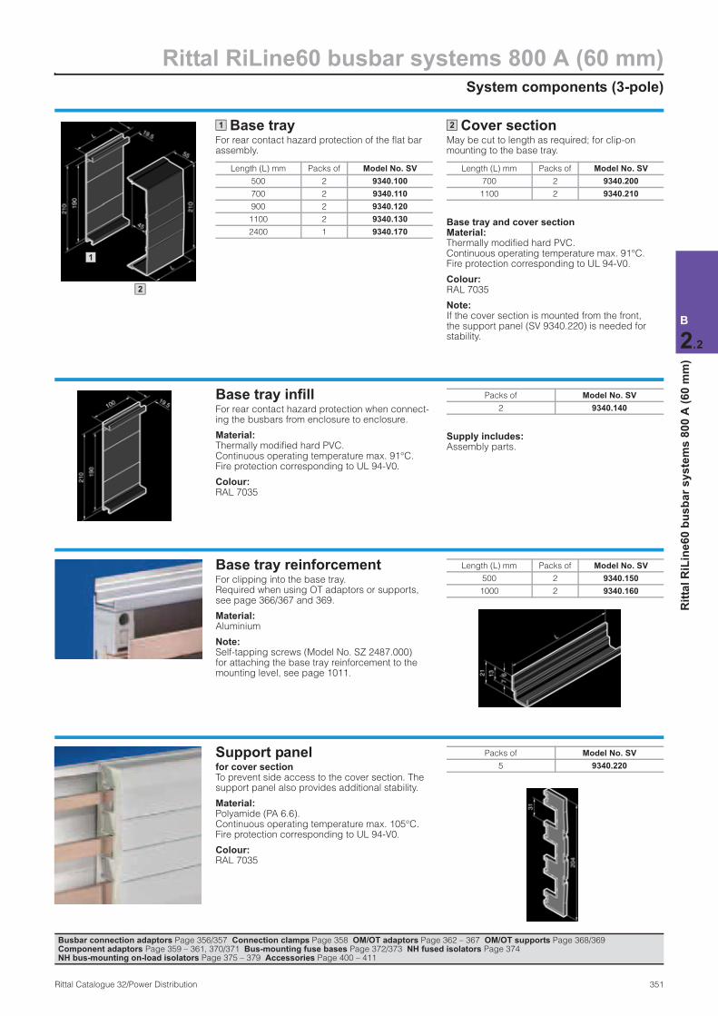
Base trayFor rear contact hazard protection of the flat bar assembly.
Cover sectionMay be cut to length as required; for clip-on mounting to the base tray.
Base tray and cover section Material:Thermally modified hard PVC. Continuous operating temperature max. 91°C. Fire protection corresponding to UL 94-V0.
Colour:RAL 7035
Note:If the cover section is mounted from the front, the support panel (SV 9340.220) is needed for stability.
Length (L) mm Packs of Model No. SV
500 2 9340.100
700 2 9340.110
900 2 9340.120
1100 2 9340.130
2400 1 9340.170
1
Length (L) mm Packs of Model No. SV
700 2 9340.200
1100 2 9340.210
2
1
2
Base tray infill For rear contact hazard protection when connect-ing the busbars from enclosure to enclosure.
Material:Thermally modified hard PVC. Continuous operating temperature max. 91°C. Fire protection corresponding to UL 94-V0.
Colour:RAL 7035
Supply includes:Assembly parts.
Packs of Model No. SV
2 9340.140
Base tray reinforcement For clipping into the base tray. Required when using OT adaptors or supports, see page 366/367 and 369.
Material:Aluminium
Note:Self-tapping screws (Model No. SZ 2487.000) for attaching the base tray reinforcement to the mounting level, see page 1011.
Length (L) mm Packs of Model No. SV
500 2 9340.150
1000 2 9340.160
Support panel for cover section To prevent side access to the cover section. The support panel also provides additional stability.
Material:Polyamide (PA 6.6). Continuous operating temperature max. 105°C. Fire protection corresponding to UL 94-V0.
Colour:RAL 7035
Packs of Model No. SV
5 9340.220
Busbar connection adaptors Page 356/357 Connection clamps Page 358 OM/OT adaptors Page 362 – 367 OM/OT supports Page 368/369 Component adaptors Page 359 – 361, 370/371 Bus-mounting fuse bases Page 372/373 NH fused isolators Page 374 NH bus-mounting on-load isolators Page 375 – 379 Accessories Page 400 – 411
Rittal RiLine60 busbar systems 800/1600 A (60 mm)PLS busbar supports (3-pole)
352 Rittal Catalogue 32/Power Distribution
B
2.2
Rit
tal
RiL
ine
60
bu
sb
ar
sy
ste
ms
80
0/1
60
0 A
(6
0 m
m)
3 1 2 3
6 5 4
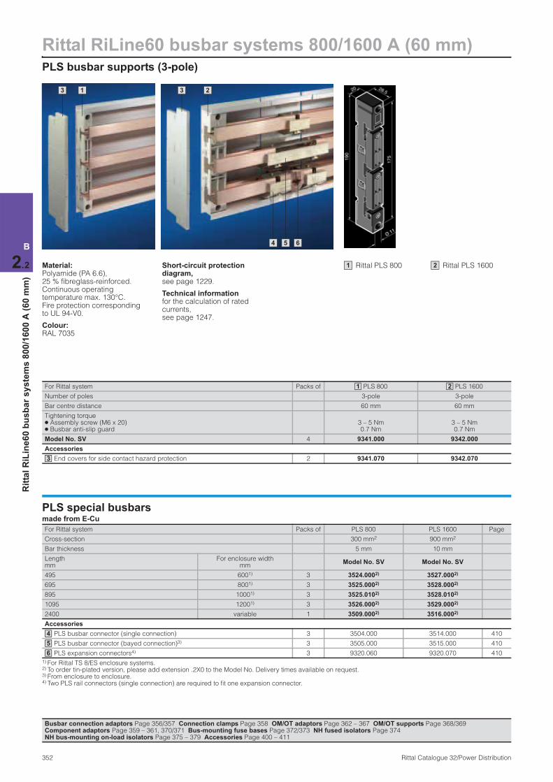
Material:Polyamide (PA 6.6), 25 % fibreglass-reinforced. Continuous operating temperature max. 130°C. Fire protection corresponding to UL 94-V0.
Colour:RAL 7035
Short-circuit protection diagram, see page 1229.
Technical information for the calculation of rated currents, see page 1247.
For Rittal system Packs of PLS 800 PLS 1600
Number of poles 3-pole 3-pole
Bar centre distance 60 mm 60 mm
Tightening torque ● Assembly screw (M6 x 20) ● Busbar anti-slip guard
3 – 5 Nm 0.7 Nm
3 – 5 Nm 0.7 Nm
Model No. SV 4 9341.000 9342.000
Accessories
End covers for side contact hazard protection 2 9341.070 9342.070
1 2
3
PLS special busbars made from E-Cu
For Rittal system Packs of PLS 800 PLS 1600 Page
Cross-section 300 mm2 900 mm2
Bar thickness 5 mm 10 mm
Length mm
For enclosure width mm
Model No. SV Model No. SV
495 6001) 3 3524.0002) 3527.0002)
695 8001) 3 3525.0002) 3528.0002)
895 10001) 3 3525.0102) 3528.0102)
1095 12001) 3 3526.0002) 3529.0002)
2400 variable 1 3509.0002) 3516.0002)
Accessories
PLS busbar connector (single connection) 3 3504.000 3514.000 410
PLS busbar connector (bayed connection)3) 3 3505.000 3515.000 410
PLS expansion connectors4) 3 9320.060 9320.070 410
1) For Rittal TS 8/ES enclosure systems. 2) To order tin-plated version, please add extension .2X0 to the Model No. Delivery times available on request. 3) From enclosure to enclosure. 4) Two PLS rail connectors (single connection) are required to fit one expansion connector.
4
5
6
Busbar connection adaptors Page 356/357 Connection clamps Page 358 OM/OT adaptors Page 362 – 367 OM/OT supports Page 368/369 Component adaptors Page 359 – 361, 370/371 Bus-mounting fuse bases Page 372/373 NH fused isolators Page 374 NH bus-mounting on-load isolators Page 375 – 379 Accessories Page 400 – 411
Rittal PLS 8001 Rittal PLS 16002
System components (3-pole)
Rittal RiLine60 busbar systems 800/1600 A (60 mm)
353Rittal Catalogue 32/Power Distribution
B
2.2
Rit
tal
RiL
ine
60
bu
sb
ar
sy
ste
ms
80
0/1
60
0 A
(6
0 m
m)
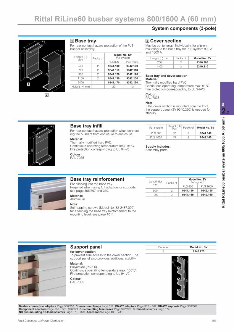
Base trayFor rear contact hazard protection of the PLS busbar assembly.
Cover sectionMay be cut to length individually, for clip-on mounting to the base tray for PLS system 800 A and 1600 A.
Base tray and cover section Material:Thermally modified hard PVC. Continuous operating temperature max. 91°C. Fire protection corresponding to UL 94-V0.
Colour:RAL 7035
Note:If the cover section is mounted from the front, the support panel (SV 9340.220) is needed for stability.
Length (L) mm
Packs of
Model No. SV For system
PLS 800 PLS 1600
500 2 9341.100 9342.100
700 2 9341.110 9342.110
900 2 9341.120 9342.120
1100 2 9341.130 9342.130
2400 1 9341.170 9342.170
Height (H) mm 32 43
1
Length (L) mm Packs of Model No. SV
700 2 9340.200
1100 2 9340.210
2
Base tray infill For rear contact hazard protection when connect-ing the busbars from enclosure to enclosure.
Material:Thermally modified hard PVC. Continuous operating temperature max. 91°C. Fire protection corresponding to UL 94-V0.
Colour:RAL 7035
Supply includes:Assembly parts.
For systemHeight (H)
mmPacks of Model No. SV
PLS 800 32 2 9341.140
PLS 1600 43 2 9342.140
Base tray reinforcement For clipping into the base tray. Required when using OT adaptors or supports, see page 366/367 and 369.
Material:Aluminium
Note:Self-tapping screws (Model No. SZ 2487.000) for attaching the base tray reinforcement to the mounting level, see page 1011.
Length (L) mm
Packs of
Model No. SV For system
PLS 800 PLS 1600
500 2 9341.150 9342.150
1000 2 9341.160 9342.160
Support panel for cover section To prevent side access to the cover section. The support panel also provides additional stability.
Material:Polyamide (PA 6.6). Continuous operating temperature max. 105°C. Fire protection corresponding to UL 94-V0.
Colour:RAL 7035
Packs of Model No. SV
5 9340.220
Busbar connection adaptors Page 356/357 Connection clamps Page 358 OM/OT adaptors Page 362 – 367 OM/OT supports Page 368/369 Component adaptors Page 359 – 361, 370/371 Bus-mounting fuse bases Page 372/373 NH fused isolators Page 374 NH bus-mounting on-load isolators Page 375 – 379 Accessories Page 400 – 411
1
2
Rittal RiLine60 busbar systems UL 508 (60 mm)Busbar supports for feeder circuits 700 A (3-pole)
354 Rittal Catalogue 32/Power Distribution
B
2.2
Rit
tal
RiL
ine
60
bu
sb
ar
sys
tem
s U
L 5
08
(6
0 m
m)
1 2
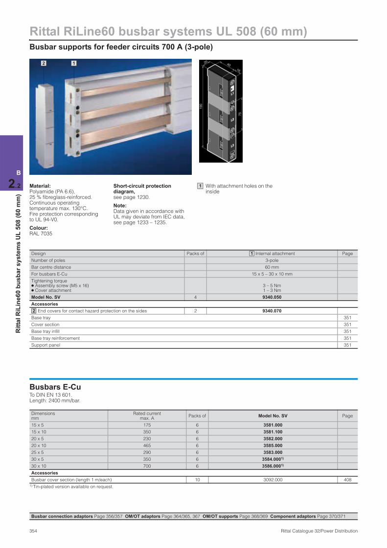
Material:Polyamide (PA 6.6), 25 % fibreglass-reinforced. Continuous operating temperature max. 130°C. Fire protection corresponding to UL 94-V0.
Colour:RAL 7035
Short-circuit protection diagram, see page 1230.
Note:Data given in accordance with UL may deviate from IEC data, see page 1233 – 1235.
Design Packs of Internal attachment Page
Number of poles 3-pole
Bar centre distance 60 mm
For busbars E-Cu 15 x 5 – 30 x 10 mm
Tightening torque ● Assembly screw (M5 x 16) ● Cover attachment
3 – 5 Nm1 – 3 Nm
Model No. SV 4 9340.050
Accessories
End covers for contact hazard protection on the sides 2 9340.070
Base tray 351
Cover section 351
Base tray infill 351
Base tray reinforcement 351
Support panel 351
1
2
Busbars E-CuTo DIN EN 13 601. Length: 2400 mm/bar.
Dimensions mm
Rated current max. A
Packs of Model No. SV Page
15 x 5 175 6 3581.000
15 x 10 350 6 3581.100
20 x 5 230 6 3582.000
20 x 10 465 6 3585.000
25 x 5 290 6 3583.000
30 x 5 350 6 3584.0001)
30 x 10 700 6 3586.0001)
Accessories
Busbar cover section (length 1 m/each) 10 3092.000 408
1) Tin-plated version available on request.
Busbar connection adaptors Page 356/357 OM/OT adaptors Page 364/365, 367 OM/OT supports Page 368/369 Component adaptors Page 370/371
With attachment holes on the inside
1
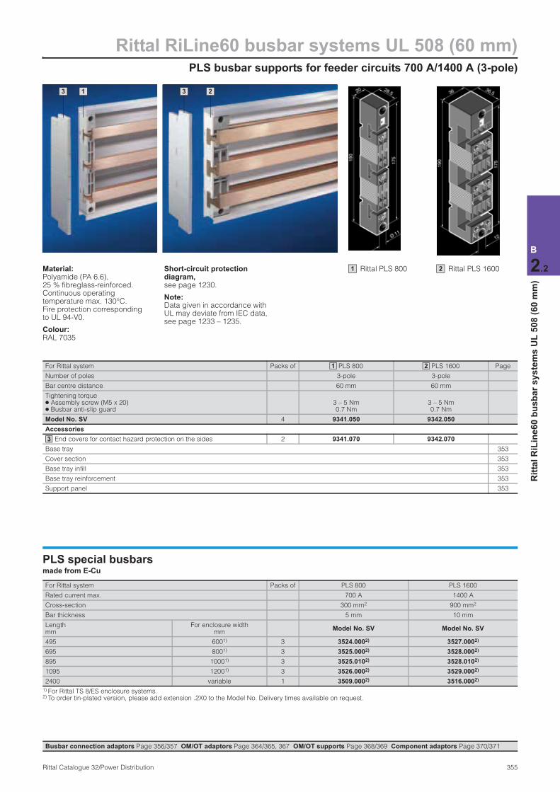
PLS busbar supports for feeder circuits 700 A/1400 A (3-pole)
Rittal RiLine60 busbar systems UL 508 (60 mm)
355Rittal Catalogue 32/Power Distribution
B
2.2
Rit
tal
RiL
ine
60
bu
sb
ar
sys
tem
s U
L 5
08
(6
0 m
m)
3 1 2 3
Material:Polyamide (PA 6.6), 25 % fibreglass-reinforced. Continuous operating temperature max. 130°C. Fire protection corresponding to UL 94-V0.
Colour:RAL 7035
Short-circuit protection diagram, see page 1230.
Note:Data given in accordance with UL may deviate from IEC data, see page 1233 – 1235.
For Rittal system Packs of PLS 800 PLS 1600 Page
Number of poles 3-pole 3-pole
Bar centre distance 60 mm 60 mm
Tightening torque ● Assembly screw (M5 x 20) ● Busbar anti-slip guard
3 – 5 Nm 0.7 Nm
3 – 5 Nm 0.7 Nm
Model No. SV 4 9341.050 9342.050
Accessories
End covers for contact hazard protection on the sides 2 9341.070 9342.070
Base tray 353
Cover section 353
Base tray infill 353
Base tray reinforcement 353
Support panel 353
1 2
3
PLS special busbars made from E-Cu
For Rittal system Packs of PLS 800 PLS 1600
Rated current max. 700 A 1400 A
Cross-section 300 mm2 900 mm2
Bar thickness 5 mm 10 mm
Length mm
For enclosure width mm
Model No. SV Model No. SV
495 6001) 3 3524.0002) 3527.0002)
695 8001) 3 3525.0002) 3528.0002)
895 10001) 3 3525.0102) 3528.0102)
1095 12001) 3 3526.0002) 3529.0002)
2400 variable 1 3509.0002) 3516.0002)
1) For Rittal TS 8/ES enclosure systems. 2) To order tin-plated version, please add extension .2X0 to the Model No. Delivery times available on request.
Busbar connection adaptors Page 356/357 OM/OT adaptors Page 364/365, 367 OM/OT supports Page 368/369 Component adaptors Page 370/371
Rittal PLS 800 1 Rittal PLS 1600 2
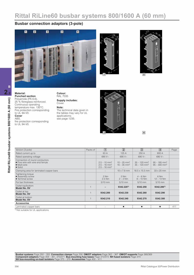
Rittal RiLine60 busbar systems 800/1600 A (60 mm)Busbar connection adaptors (3-pole)
356 Rittal Catalogue 32/Power Distribution
B
2.2
Rit
tal
RiL
ine
60
bu
sb
ar
sy
ste
ms
80
0/1
60
0 A
(6
0 m
m)
1 2 3 3 4
Material:Punched section Polyamide (PA 6.6), 25 % fibreglass-reinforced. Continuous operating temperature max. 130°C. Fire protection corresponding to UL 94-V0. Cover ABS, fire protection corresponding to UL 94-V0.
Colour:RAL 7035
Supply includes:Cover.
Note:The technical data given in the tables may vary for UL applications; see page 1235.
Version (3-pole) Packs of Page
Rated current up to 63 A 125 A 250 A 800 A
Rated operating voltage 690 V~ 690 V~ 690 V~ 690 V~
Connection of round conductors ● Fine wire with wire end ferrule ● Multi-wire ● Solid
2.5 – 10 mm2 2.5 – 16 mm2 2.5 – 16 mm2
10 – 25 mm2 16 – 35 mm2
–
35 – 120 mm2 35 – 120 mm2
–
95 – 185 mm2 95 – 300 mm2
–
Clamping area for laminated copper bars – 10 x 7.8 mm 18.5 x 15.5 mm 33 x 20 mm
Tightening torque ● Assembly screw ● Terminal screw
2 Nm 2.5 Nm
2 Nm 2 – 3 Nm
4 – 6 Nm 8 – 10 Nm
6 Nm 12 – 14 Nm
For bar thickness 5/10 mm 5/10 mm 5/10 mm 5/10 mm
Outlet top/bottomModel No. SV
1 – 9342.2201) 9342.250 9342.2801)
Outlet at topModel No. SV
1 9342.200 9342.230 9342.260 9342.290
Outlet at bottomModel No. SV
1 9342.210 9342.240 9342.270 9342.300
Accessories
Laminated copper bars – n n n 411
1) Not suitable for UL applications.
1 2 3 4
Busbar systems Page 350 – 355 Connection clamps Page 358 OM/OT adaptors Page 362 – 367 OM/OT supports Page 368/369 Component adaptors Page 359 – 361, 370/371 Bus-mounting fuse bases Page 372/373 NH fused isolators Page 374 NH bus-mounting on-load isolators Page 375 – 379 Accessories Page 400 – 411
1 2
3 4
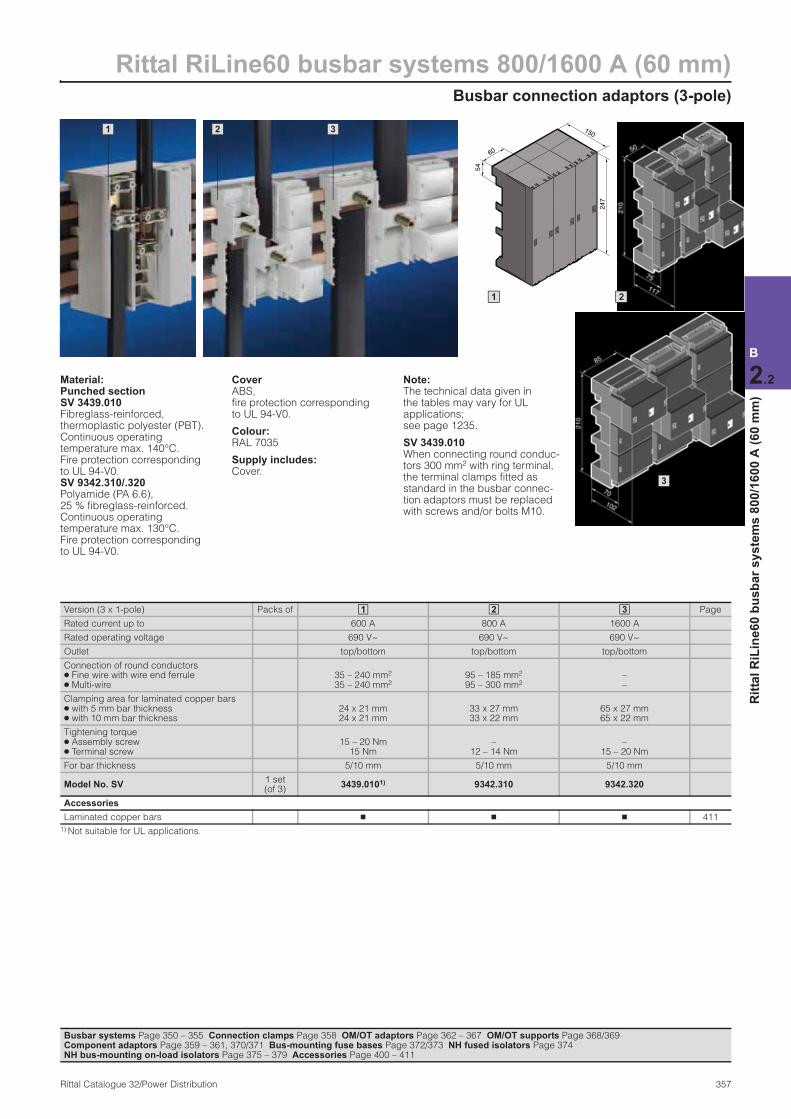
Busbar connection adaptors (3-pole)
Rittal RiLine60 busbar systems 800/1600 A (60 mm)
357Rittal Catalogue 32/Power Distribution
B
2.2
Rit
tal
RiL
ine
60
bu
sb
ar
sy
ste
ms
80
0/1
60
0 A
(6
0 m
m)
1 2 3 150
60
54
247
1 2
3
Busbar systems Page 350 – 355 Connection clamps Page 358 OM/OT adaptors Page 362 – 367 OM/OT supports Page 368/369 Component adaptors Page 359 – 361, 370/371 Bus-mounting fuse bases Page 372/373 NH fused isolators Page 374 NH bus-mounting on-load isolators Page 375 – 379 Accessories Page 400 – 411
Material:Punched section SV 3439.010Fibreglass-reinforced, thermoplastic polyester (PBT). Continuous operating temperature max. 140°C. Fire protection corresponding to UL 94-V0. SV 9342.310/.320Polyamide (PA 6.6), 25 % fibreglass-reinforced.Continuous operating temperature max. 130°C. Fire protection corresponding to UL 94-V0.
Cover ABS, fire protection corresponding to UL 94-V0.
Colour:RAL 7035
Supply includes:Cover.
Note:The technical data given in the tables may vary for UL applications; see page 1235.
SV 3439.010 When connecting round conduc-tors 300 mm2 with ring terminal, the terminal clamps fitted as standard in the busbar connec-tion adaptors must be replaced with screws and/or bolts M10.
Version (3 x 1-pole) Packs of Page
Rated current up to 600 A 800 A 1600 A
Rated operating voltage 690 V~ 690 V~ 690 V~
Outlet top/bottom top/bottom top/bottom
Connection of round conductors ● Fine wire with wire end ferrule ● Multi-wire
35 – 240 mm2 35 – 240 mm2
95 – 185 mm2
95 – 300 mm2– –
Clamping area for laminated copper bars ● with 5 mm bar thickness ● with 10 mm bar thickness
24 x 21 mm 24 x 21 mm
33 x 27 mm 33 x 22 mm
65 x 27 mm 65 x 22 mm
Tightening torque ● Assembly screw ● Terminal screw
15 – 20 Nm 15 Nm
– 12 – 14 Nm
– 15 – 20 Nm
For bar thickness 5/10 mm 5/10 mm 5/10 mm
Model No. SV1 set(of 3)
3439.0101) 9342.310 9342.320
Accessories
Laminated copper bars n n n 411
1) Not suitable for UL applications.
1 2 3
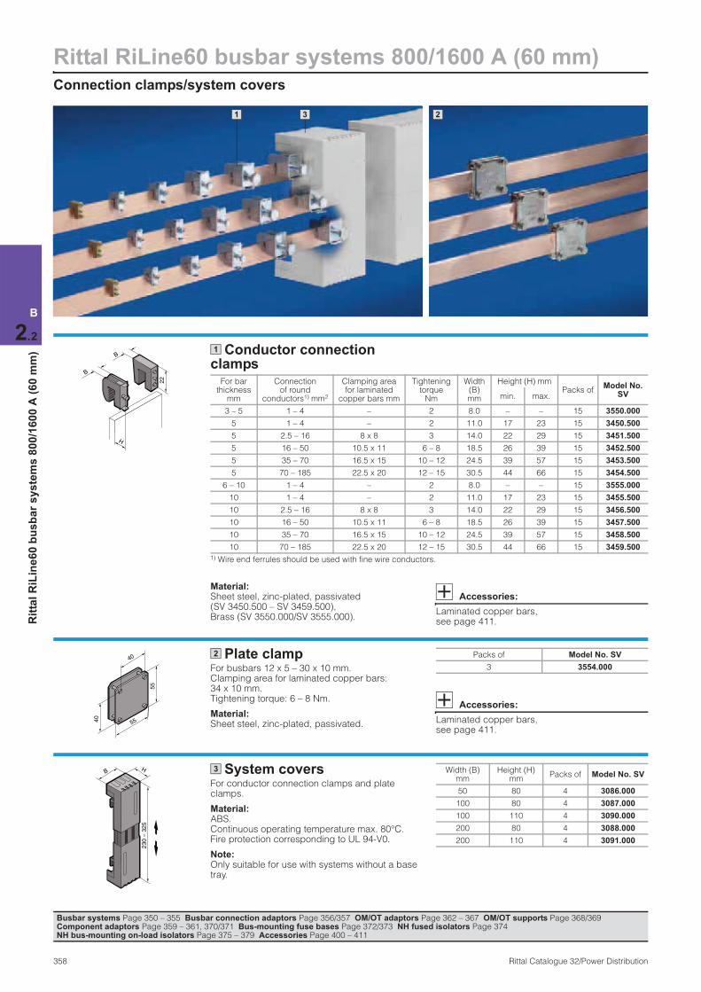
Rittal RiLine60 busbar systems 800/1600 A (60 mm)Connection clamps/system covers
358 Rittal Catalogue 32/Power Distribution
B
2.2
Rit
tal
RiL
ine
60
bu
sb
ar
sy
ste
ms
80
0/1
60
0 A
(6
0 m
m)
1 3 2
Conductor connection clamps
Material:Sheet steel, zinc-plated, passivated (SV 3450.500 – SV 3459.500), Brass (SV 3550.000/SV 3555.000).
Accessories:
Laminated copper bars, see page 411.
22
B
B
H
1
For bar thickness
mm
Connection of round
conductors1) mm2
Clamping area for laminated
copper bars mm
Tightening torque
Nm
Width (B) mm
Height (H) mmPacks of
Model No. SVmin. max.
3 – 5 1 – 4 – 2 8.0 – – 15 3550.000
5 1 – 4 – 2 11.0 17 23 15 3450.500
5 2.5 – 16 8 x 8 3 14.0 22 29 15 3451.500
5 16 – 50 10.5 x 11 6 – 8 18.5 26 39 15 3452.500
5 35 – 70 16.5 x 15 10 – 12 24.5 39 57 15 3453.500
5 70 – 185 22.5 x 20 12 – 15 30.5 44 66 15 3454.500
6 – 10 1 – 4 – 2 8.0 – – 15 3555.000
10 1 – 4 – 2 11.0 17 23 15 3455.500
10 2.5 – 16 8 x 8 3 14.0 22 29 15 3456.500
10 16 – 50 10.5 x 11 6 – 8 18.5 26 39 15 3457.500
10 35 – 70 16.5 x 15 10 – 12 24.5 39 57 15 3458.500
10 70 – 185 22.5 x 20 12 – 15 30.5 44 66 15 3459.500
1) Wire end ferrules should be used with fine wire conductors.
Plate clamp For busbars 12 x 5 – 30 x 10 mm. Clamping area for laminated copper bars: 34 x 10 mm. Tightening torque: 6 – 8 Nm.
Material:Sheet steel, zinc-plated, passivated.
Accessories:
Laminated copper bars, see page 411.
55
5540
402 Packs of Model No. SV
3 3554.000
System coversFor conductor connection clamps and plate clamps.
Material:ABS. Continuous operating temperature max. 80°C. Fire protection corresponding to UL 94-V0.
Note:Only suitable for use with systems without a base tray.
B
230 –
325
H 3 Width (B) mm
Height (H) mm
Packs of Model No. SV
50 80 4 3086.000
100 80 4 3087.000
100 110 4 3090.000
200 80 4 3088.000
200 110 4 3091.000
Busbar systems Page 350 – 355 Busbar connection adaptors Page 356/357 OM/OT adaptors Page 362 – 367 OM/OT supports Page 368/369 Component adaptors Page 359 – 361, 370/371 Bus-mounting fuse bases Page 372/373 NH fused isolators Page 374 NH bus-mounting on-load isolators Page 375 – 379 Accessories Page 400 – 411
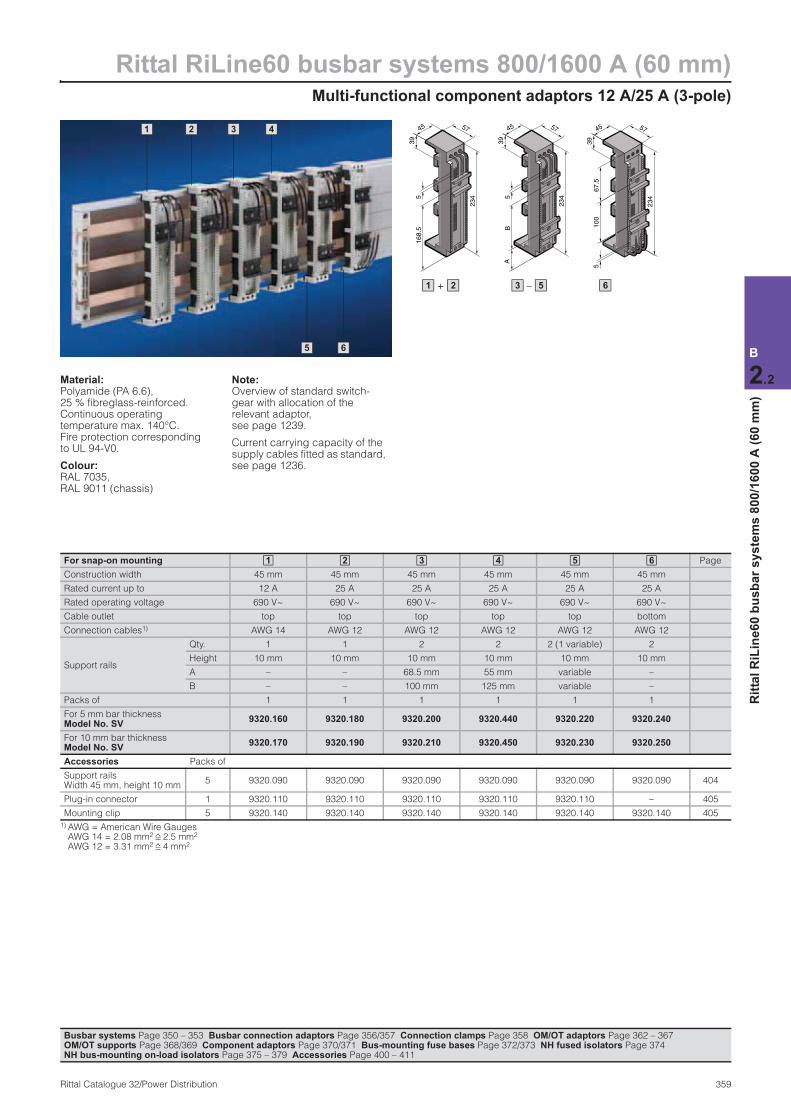
Multi-functional component adaptors 12 A/25 A (3-pole)
Rittal RiLine60 busbar systems 800/1600 A (60 mm)
359Rittal Catalogue 32/Power Distribution
B
2.2
Rit
tal
RiL
ine
60
bu
sb
ar
sy
ste
ms
80
0/1
60
0 A
(6
0 m
m)
2 1 3 4
5 6
39
45
234
57
168.5
5
234
39
45 57
BA
5
234
45 57
67.5
100
5
39
+ 1 2 – 3 5 6
Material:Polyamide (PA 6.6), 25 % fibreglass-reinforced. Continuous operating temperature max. 140°C. Fire protection corresponding to UL 94-V0.
Colour:RAL 7035, RAL 9011 (chassis)
Note:Overview of standard switch-gear with allocation of the relevant adaptor, see page 1239.
Current carrying capacity of the supply cables fitted as standard, see page 1236.
For snap-on mounting Page
Construction width 45 mm 45 mm 45 mm 45 mm 45 mm 45 mm
Rated current up to 12 A 25 A 25 A 25 A 25 A 25 A
Rated operating voltage 690 V~ 690 V~ 690 V~ 690 V~ 690 V~ 690 V~
Cable outlet top top top top top bottom
Connection cables1) AWG 14 AWG 12 AWG 12 AWG 12 AWG 12 AWG 12
Support rails
Qty. 1 1 2 2 2 (1 variable) 2
Height 10 mm 10 mm 10 mm 10 mm 10 mm 10 mm
A – – 68.5 mm 55 mm variable –
B – – 100 mm 125 mm variable –
Packs of 1 1 1 1 1 1
For 5 mm bar thicknessModel No. SV
9320.160 9320.180 9320.200 9320.440 9320.220 9320.240
For 10 mm bar thicknessModel No. SV
9320.170 9320.190 9320.210 9320.450 9320.230 9320.250
Accessories Packs of
Support rails Width 45 mm, height 10 mm
5 9320.090 9320.090 9320.090 9320.090 9320.090 9320.090 404
Plug-in connector 1 9320.110 9320.110 9320.110 9320.110 9320.110 – 405
Mounting clip 5 9320.140 9320.140 9320.140 9320.140 9320.140 9320.140 405
1) AWG = American Wire Gauges AWG 14 = 2.08 mm2 2.5 mm2 AWG 12 = 3.31 mm2 4 mm2
1 2 3 4 5 6
Busbar systems Page 350 – 353 Busbar connection adaptors Page 356/357 Connection clamps Page 358 OM/OT adaptors Page 362 – 367OM/OT supports Page 368/369 Component adaptors Page 370/371 Bus-mounting fuse bases Page 372/373 NH fused isolators Page 374 NH bus-mounting on-load isolators Page 375 – 379 Accessories Page 400 – 411
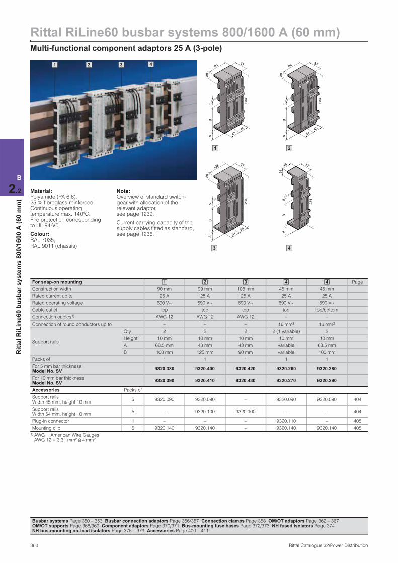
Rittal RiLine60 busbar systems 800/1600 A (60 mm)Multi-functional component adaptors 25 A (3-pole)
360 Rittal Catalogue 32/Power Distribution
B
2.2
Rit
tal
RiL
ine
60
bu
sb
ar
sy
ste
ms
80
0/1
60
0 A
(6
0 m
m)
Material:Polyamide (PA 6.6), 25 % fibreglass-reinforced. Continuous operating temperature max. 140°C. Fire protection corresponding to UL 94-V0.
Colour:RAL 7035, RAL 9011 (chassis)
Note:Overview of standard switch-gear with allocation of the relevant adaptor, see page 1239.
Current carrying capacity of the supply cables fitted as standard, see page 1236.
For snap-on mounting Page
Construction width 90 mm 99 mm 108 mm 45 mm 45 mm
Rated current up to 25 A 25 A 25 A 25 A 25 A
Rated operating voltage 690 V~ 690 V~ 690 V~ 690 V~ 690 V~
Cable outlet top top top top top/bottom
Connection cables1) AWG 12 AWG 12 AWG 12 – –
Connection of round conductors up to – – – 16 mm2 16 mm2
Support rails
Qty. 2 2 2 2 (1 variable) 2
Height 10 mm 10 mm 10 mm 10 mm 10 mm
A 68.5 mm 43 mm 43 mm variable 68.5 mm
B 100 mm 125 mm 90 mm variable 100 mm
Packs of 1 1 1 1 1
For 5 mm bar thickness Model No. SV
9320.380 9320.400 9320.420 9320.260 9320.280
For 10 mm bar thickness Model No. SV
9320.390 9320.410 9320.430 9320.270 9320.290
Accessories Packs of
Support rails Width 45 mm, height 10 mm
5 9320.090 9320.090 – 9320.090 9320.090 404
Support rails Width 54 mm, height 10 mm
5 – 9320.100 9320.100 – – 404
Plug-in connector 1 – – – 9320.110 – 405
Mounting clip 5 9320.140 9320.140 – 9320.140 9320.140 405
1) AWG = American Wire Gauges AWG 12 = 3.31 mm2 4 mm2
1 2 3 4 4
Busbar systems Page 350 – 353 Busbar connection adaptors Page 356/357 Connection clamps Page 358 OM/OT adaptors Page 362 – 367 OM/OT supports Page 368/369 Component adaptors Page 370/371 Bus-mounting fuse bases Page 372/373 NH fused isolators Page 374 NH bus-mounting on-load isolators Page 375 – 379 Accessories Page 400 – 411
2 1 3 4 99
234
39
54
45
57
BA
5
90
234
39
45
45
57
BA
5
108
234
39
54
54
57
BA
5
1
234
39
45 57
BA
5
4
2
3
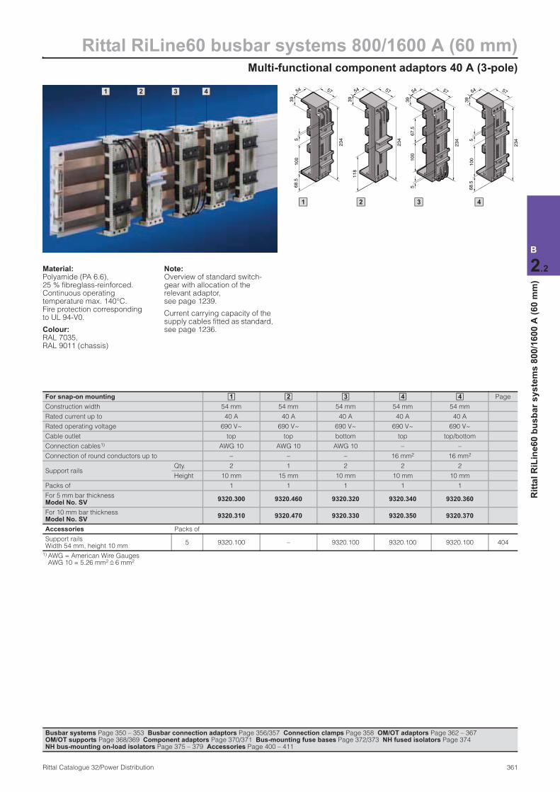
Multi-functional component adaptors 40 A (3-pole)
Rittal RiLine60 busbar systems 800/1600 A (60 mm)
361Rittal Catalogue 32/Power Distribution
B
2.2
Rit
tal
RiL
ine
60
bu
sb
ar
sy
ste
ms
80
0/1
60
0 A
(6
0 m
m)
Material:Polyamide (PA 6.6), 25 % fibreglass-reinforced. Continuous operating temperature max. 140°C. Fire protection corresponding to UL 94-V0.
Colour:RAL 7035, RAL 9011 (chassis)
Note:Overview of standard switch-gear with allocation of the relevant adaptor, see page 1239.
Current carrying capacity of the supply cables fitted as standard, see page 1236.
For snap-on mounting Page
Construction width 54 mm 54 mm 54 mm 54 mm 54 mm
Rated current up to 40 A 40 A 40 A 40 A 40 A
Rated operating voltage 690 V~ 690 V~ 690 V~ 690 V~ 690 V~
Cable outlet top top bottom top top/bottom
Connection cables1) AWG 10 AWG 10 AWG 10 – –
Connection of round conductors up to – – – 16 mm2 16 mm2
Support railsQty. 2 1 2 2 2
Height 10 mm 15 mm 10 mm 10 mm 10 mm
Packs of 1 1 1 1 1
For 5 mm bar thicknessModel No. SV
9320.300 9320.460 9320.320 9320.340 9320.360
For 10 mm bar thicknessModel No. SV
9320.310 9320.470 9320.330 9320.350 9320.370
Accessories Packs of
Support rails Width 54 mm, height 10 mm
5 9320.100 – 9320.100 9320.100 9320.100 404
1) AWG = American Wire Gauges AWG 10 = 5.26 mm2 6 mm2
1 2 3 4 4
Busbar systems Page 350 – 353 Busbar connection adaptors Page 356/357 Connection clamps Page 358 OM/OT adaptors Page 362 – 367 OM/OT supports Page 368/369 Component adaptors Page 370/371 Bus-mounting fuse bases Page 372/373 NH fused isolators Page 374 NH bus-mounting on-load isolators Page 375 – 379 Accessories Page 400 – 411
2 1 3 4
234
39
54 57
100
68.5
5
54 57
67.5
100
234
5
39
39
54 57
118
234
1 32
39
54 57
100
68.5
2345
4
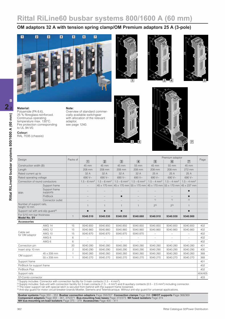
Rittal RiLine60 busbar systems 800/1600 A (60 mm)OM adaptors 32 A with tension spring clamp/OM Premium adaptors 25 A (3-pole)
362 Rittal Catalogue 32/Power Distribution
B
2.2
Rit
tal
RiL
ine
60
bu
sb
ar
sy
ste
ms
80
0/1
60
0 A
(6
0 m
m)
1 2 3 4 7 5 6
Material:Polyamide (PA 6.6), 25 % fibreglass-reinforced. Continuous operating temperature max. 130°C. Fire protection corresponding to UL 94-V0.
Colour:RAL 7035 (chassis)
Note:Overview of standard commer-cially available switchgear with allocation of the relevant adaptor, see page 1240.
Design Packs ofPremium adaptor
Page
Construction width (B) 45 mm 45 mm 45 mm 55 mm 45 mm 55 mm 45 mm
Length 208 mm 208 mm 208 mm 208 mm 208 mm 208 mm 272 mm
Rated current up to 32 A 32 A 32 A 32 A 25 A 25 A 25 A
Rated operating voltage 690 V~ 690 V~ 690 V~ 690 V~ 690 V~ 690 V~ 690 V~
Connection of round conductors 1.5 – 6 mm2 1.5 – 6 mm2 1.5 – 6 mm2 1.5 – 6 mm2 1.5 – 4 mm2 1.5 – 4 mm2 1.5 – 4 mm2
With
Support frame – 45 x 170 mm 45 x 170 mm 55 x 170 mm 45 x 170 mm 55 x 170 mm 45 x 237 mm
Support frame supports
– – – – – – n
PinBlock – – n – – – n
Connector outlet – – – – 1) 1) 2)
Number of support rails, height 10 mm
1 1 1 1 23) 23) 1
Support rail with anti-slip guard4) n n n – – – n
For 5/10 mm bar thickness Model No. SV
1 9340.510 9340.530 9340.550 9340.660 9340.910 9340.930 9340.900
Accessories
Cable set for OM adaptor
AWG 14 15 9340.850 9340.850 9340.850 9340.850 9340.850 9340.850 9340.850 402
AWG 12 15 9340.860 9340.860 9340.860 9340.860 9340.860 9340.860 9340.860 402
AWG 10 15 9340.870 9340.870 9340.870 9340.870 – – – 402
AWG 8 6 – – – – – – – 402
AWG 6 6 – – – – – – – 402
Connection pin 20 9340.280 9340.280 9340.280 9340.280 9340.280 9340.280 9340.280 401
Insert strip 10 mm 2 9340.290 9340.290 9340.290 9340.290 9340.290 9340.290 9340.290 400
OM support45 x 208 mm 1 9340.260 9340.260 9340.260 9340.260 9340.260 9340.260 9340.260 368
55 x 208 mm 1 9340.270 9340.270 9340.270 9340.270 9340.270 9340.270 9340.270 368
Support frame 401
PinBlock for support frame 402
PinBlock Plus 402
Support rails 404/405
ST-Combi connector 403
1) Supply includes: Connector with connection facility for 3 main contacts (1.5 – 4 mm2).2) Supply includes: Sub-unit with connection facility for 3 main contacts (1.5 – 4 mm2) and 8 auxiliary contacts (0.5 – 2.5 mm2) including connector. 3) The lower support rail with special latch is secured from behind with the support frame loosened.4) Anti-slip guard for motor circuit-breaker brands Moeller, Siemens and Telemecanique. Without anti-slip guard for universal applications.
1 2 3 4 5 6 7
1 + 2 4 3
7+ 5 6
Busbar systems Page 350 – 353 Busbar connection adaptors Page 356/357 Connection clamps Page 358 OM/OT supports Page 368/369 Component adaptors Page 359 – 361, 370/371 Bus-mounting fuse bases Page 372/373 NH fused isolators Page 374 NH bus-mounting on-load isolators Page 375 – 379 Accessories Page 400 – 411
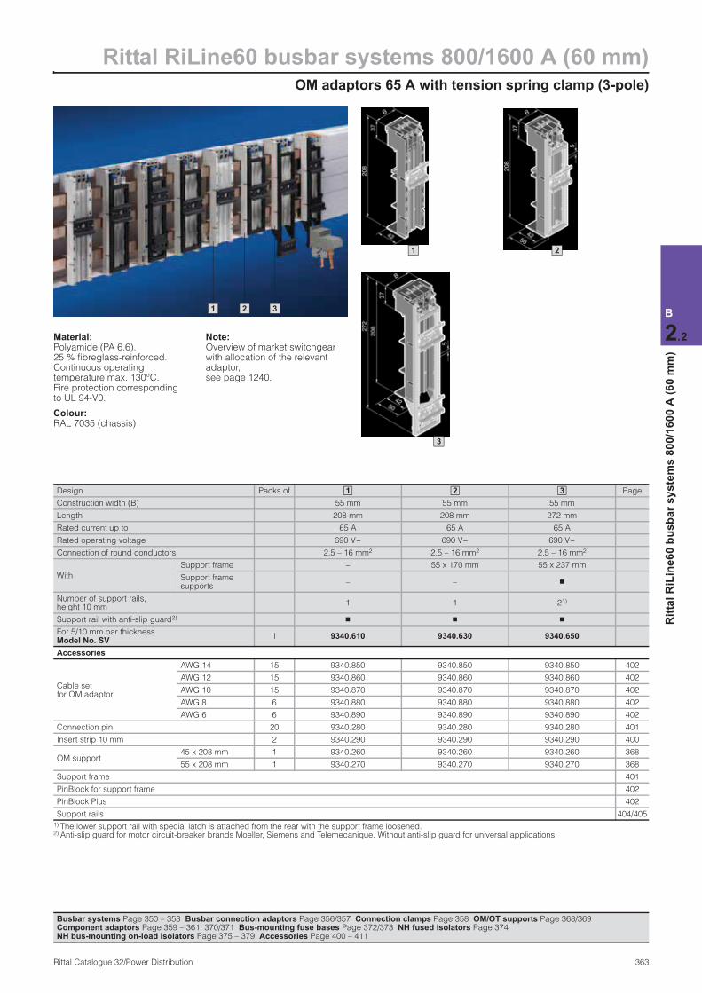
OM adaptors 65 A with tension spring clamp (3-pole)
Rittal RiLine60 busbar systems 800/1600 A (60 mm)
363Rittal Catalogue 32/Power Distribution
B
2.2
Rit
tal
RiL
ine
60
bu
sb
ar
sy
ste
ms
80
0/1
60
0 A
(6
0 m
m)
1 2 3
Material:Polyamide (PA 6.6), 25 % fibreglass-reinforced. Continuous operating temperature max. 130°C. Fire protection corresponding to UL 94-V0.
Colour:RAL 7035 (chassis)
Note:Overview of market switchgear with allocation of the relevant adaptor, see page 1240.
Design Packs of Page
Construction width (B) 55 mm 55 mm 55 mm
Length 208 mm 208 mm 272 mm
Rated current up to 65 A 65 A 65 A
Rated operating voltage 690 V~ 690 V~ 690 V~
Connection of round conductors 2.5 – 16 mm2 2.5 – 16 mm2 2.5 – 16 mm2
With
Support frame – 55 x 170 mm 55 x 237 mm
Support frame supports
– – n
Number of support rails, height 10 mm
1 1 21)
Support rail with anti-slip guard2)n n n
For 5/10 mm bar thickness Model No. SV
1 9340.610 9340.630 9340.650
Accessories
Cable set for OM adaptor
AWG 14 15 9340.850 9340.850 9340.850 402
AWG 12 15 9340.860 9340.860 9340.860 402
AWG 10 15 9340.870 9340.870 9340.870 402
AWG 8 6 9340.880 9340.880 9340.880 402
AWG 6 6 9340.890 9340.890 9340.890 402
Connection pin 20 9340.280 9340.280 9340.280 401
Insert strip 10 mm 2 9340.290 9340.290 9340.290 400
OM support45 x 208 mm 1 9340.260 9340.260 9340.260 368
55 x 208 mm 1 9340.270 9340.270 9340.270 368
Support frame 401
PinBlock for support frame 402
PinBlock Plus 402
Support rails 404/405
1) The lower support rail with special latch is attached from the rear with the support frame loosened. 2) Anti-slip guard for motor circuit-breaker brands Moeller, Siemens and Telemecanique. Without anti-slip guard for universal applications.
1 2 3
1 2
3
Busbar systems Page 350 – 353 Busbar connection adaptors Page 356/357 Connection clamps Page 358 OM/OT supports Page 368/369 Component adaptors Page 359 – 361, 370/371 Bus-mounting fuse bases Page 372/373 NH fused isolators Page 374 NH bus-mounting on-load isolators Page 375 – 379 Accessories Page 400 – 411
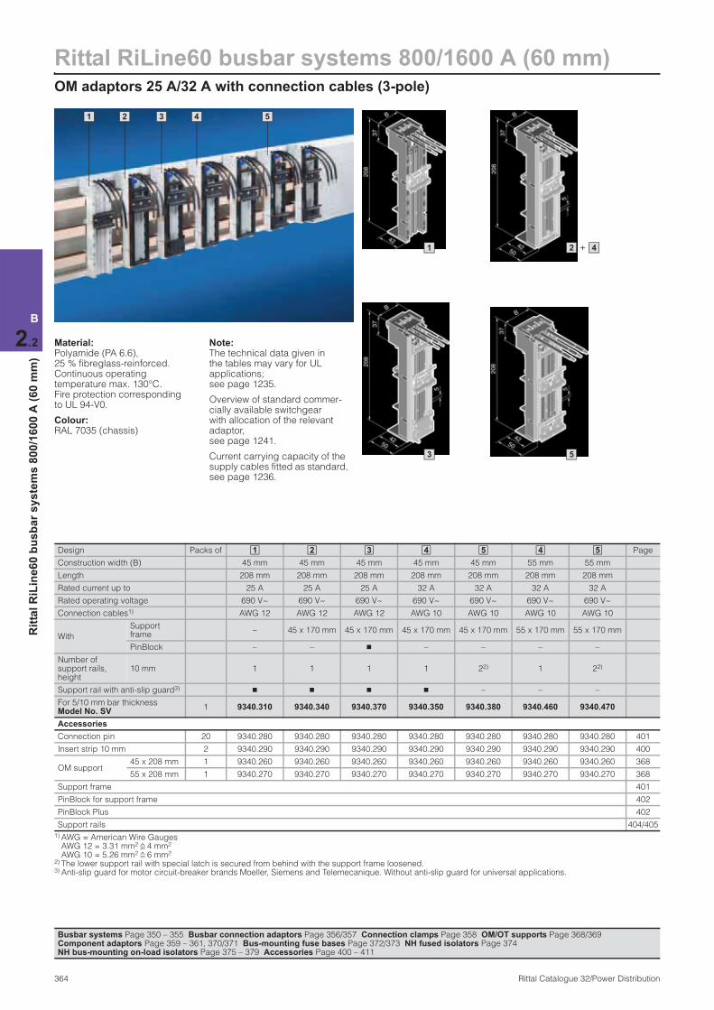
Rittal RiLine60 busbar systems 800/1600 A (60 mm)OM adaptors 25 A/32 A with connection cables (3-pole)
364 Rittal Catalogue 32/Power Distribution
B
2.2
Rit
tal
RiL
ine
60
bu
sb
ar
sy
ste
ms
80
0/1
60
0 A
(6
0 m
m)
1 2 3 4 5
Material:Polyamide (PA 6.6), 25 % fibreglass-reinforced. Continuous operating temperature max. 130°C. Fire protection corresponding to UL 94-V0.
Colour:RAL 7035 (chassis)
Note:The technical data given in the tables may vary for UL applications; see page 1235.
Overview of standard commer-cially available switchgear with allocation of the relevant adaptor, see page 1241.
Current carrying capacity of the supply cables fitted as standard, see page 1236.
Design Packs of Page
Construction width (B) 45 mm 45 mm 45 mm 45 mm 45 mm 55 mm 55 mm
Length 208 mm 208 mm 208 mm 208 mm 208 mm 208 mm 208 mm
Rated current up to 25 A 25 A 25 A 32 A 32 A 32 A 32 A
Rated operating voltage 690 V~ 690 V~ 690 V~ 690 V~ 690 V~ 690 V~ 690 V~
Connection cables1) AWG 12 AWG 12 AWG 12 AWG 10 AWG 10 AWG 10 AWG 10
With
Support frame
– 45 x 170 mm 45 x 170 mm 45 x 170 mm 45 x 170 mm 55 x 170 mm 55 x 170 mm
PinBlock – – n – – – –
Number of support rails, height
10 mm 1 1 1 1 22) 1 22)
Support rail with anti-slip guard3) n n n n – – –
For 5/10 mm bar thickness Model No. SV
1 9340.310 9340.340 9340.370 9340.350 9340.380 9340.460 9340.470
Accessories
Connection pin 20 9340.280 9340.280 9340.280 9340.280 9340.280 9340.280 9340.280 401
Insert strip 10 mm 2 9340.290 9340.290 9340.290 9340.290 9340.290 9340.290 9340.290 400
OM support45 x 208 mm 1 9340.260 9340.260 9340.260 9340.260 9340.260 9340.260 9340.260 368
55 x 208 mm 1 9340.270 9340.270 9340.270 9340.270 9340.270 9340.270 9340.270 368
Support frame 401
PinBlock for support frame 402
PinBlock Plus 402
Support rails 404/405
1) AWG = American Wire Gauges AWG 12 = 3.31 mm2 4 mm2 AWG 10 = 5.26 mm2 6 mm2
2) The lower support rail with special latch is secured from behind with the support frame loosened. 3) Anti-slip guard for motor circuit-breaker brands Moeller, Siemens and Telemecanique. Without anti-slip guard for universal applications.
1 2 3 4 5 4 5
3 5
1 + 2 4
Busbar systems Page 350 – 355 Busbar connection adaptors Page 356/357 Connection clamps Page 358 OM/OT supports Page 368/369 Component adaptors Page 359 – 361, 370/371 Bus-mounting fuse bases Page 372/373 NH fused isolators Page 374 NH bus-mounting on-load isolators Page 375 – 379 Accessories Page 400 – 411
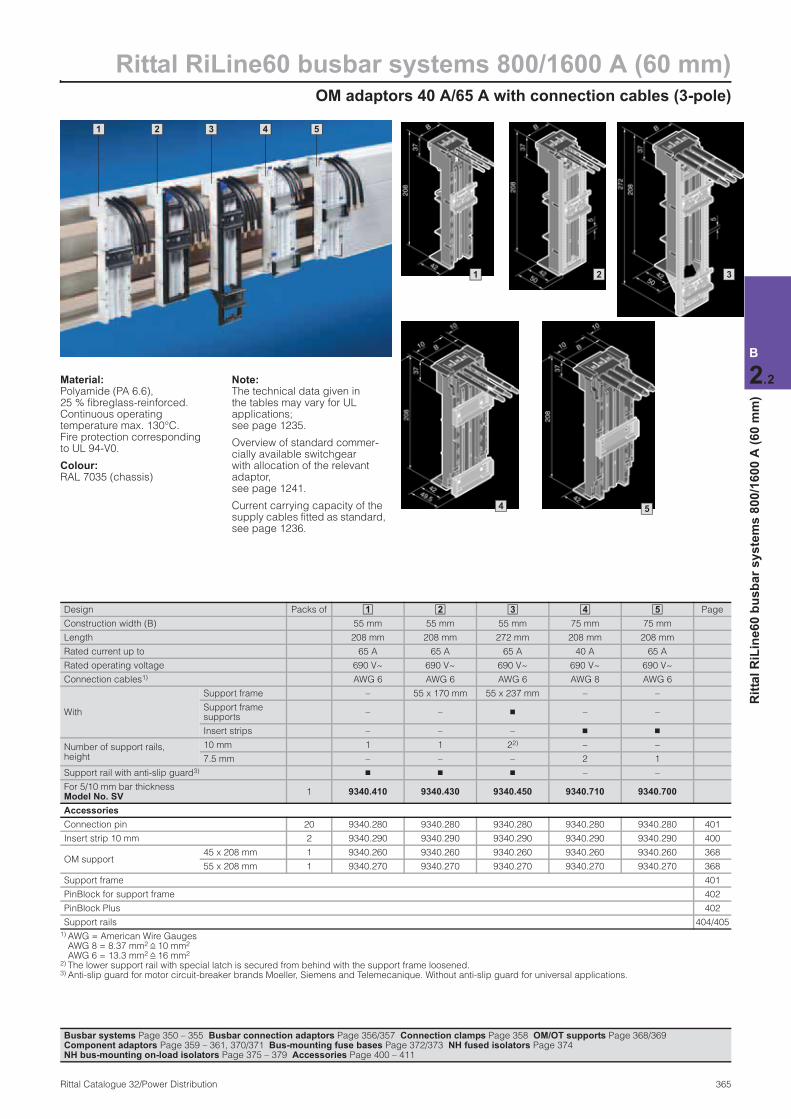
OM adaptors 40 A/65 A with connection cables (3-pole)
Rittal RiLine60 busbar systems 800/1600 A (60 mm)
365Rittal Catalogue 32/Power Distribution
B
2.2
Rit
tal
RiL
ine
60
bu
sb
ar
sy
ste
ms
80
0/1
60
0 A
(6
0 m
m)
1 2 3 4 5
3
Material:Polyamide (PA 6.6), 25 % fibreglass-reinforced. Continuous operating temperature max. 130°C. Fire protection corresponding to UL 94-V0.
Colour:RAL 7035 (chassis)
Note:The technical data given in the tables may vary for UL applications; see page 1235.
Overview of standard commer-cially available switchgear with allocation of the relevant adaptor, see page 1241.
Current carrying capacity of the supply cables fitted as standard, see page 1236.
Design Packs of Page
Construction width (B) 55 mm 55 mm 55 mm 75 mm 75 mm
Length 208 mm 208 mm 272 mm 208 mm 208 mm
Rated current up to 65 A 65 A 65 A 40 A 65 A
Rated operating voltage 690 V~ 690 V~ 690 V~ 690 V~ 690 V~
Connection cables1) AWG 6 AWG 6 AWG 6 AWG 8 AWG 6
With
Support frame – 55 x 170 mm 55 x 237 mm – –
Support frame supports
– – n – –
Insert strips – – – n n
Number of support rails, height
10 mm 1 1 22) – –
7.5 mm – – – 2 1
Support rail with anti-slip guard3) n n n – –
For 5/10 mm bar thickness Model No. SV
1 9340.410 9340.430 9340.450 9340.710 9340.700
Accessories
Connection pin 20 9340.280 9340.280 9340.280 9340.280 9340.280 401
Insert strip 10 mm 2 9340.290 9340.290 9340.290 9340.290 9340.290 400
OM support45 x 208 mm 1 9340.260 9340.260 9340.260 9340.260 9340.260 368
55 x 208 mm 1 9340.270 9340.270 9340.270 9340.270 9340.270 368
Support frame 401
PinBlock for support frame 402
PinBlock Plus 402
Support rails 404/405
1) AWG = American Wire Gauges AWG 8 = 8.37 mm2 10 mm2 AWG 6 = 13.3 mm2 16 mm2
2) The lower support rail with special latch is secured from behind with the support frame loosened. 3) Anti-slip guard for motor circuit-breaker brands Moeller, Siemens and Telemecanique. Without anti-slip guard for universal applications.
1 2 3 4 5
1 2
4 5
Busbar systems Page 350 – 355 Busbar connection adaptors Page 356/357 Connection clamps Page 358 OM/OT supports Page 368/369 Component adaptors Page 359 – 361, 370/371 Bus-mounting fuse bases Page 372/373 NH fused isolators Page 374 NH bus-mounting on-load isolators Page 375 – 379 Accessories Page 400 – 411

Rittal RiLine60 busbar systems 800/1600 A (60 mm)OT adaptors 32 A/65 A with tension spring clamp/OT Premium adaptors 25 A (3-pole)
366 Rittal Catalogue 32/Power Distribution
B
2.2
Rit
tal
RiL
ine
60
bu
sb
ar
sy
ste
ms
80
0/1
60
0 A
(6
0 m
m)
1 2 3 4
5 6 7 8
DesignPacks
of
Premium adaptor Page
Construction width (B) 45 mm 45 mm 45 mm 55 mm 55 mm 55 mm 55 mm 45 mm
Length 230 mm 230 mm 230 mm 230 mm 230 mm 230 mm 272 mm 272 mm
Rated current up to 32 A 32 A 32 A 32 A 65 A 65 A 65 A 25 A
Rated operating voltage 690 V~ 690 V~ 690 V~ 690 V~ 690 V~ 690 V~ 690 V~ 690 V~
Connection of round conductors 1.5 – 6 mm2 1.5 – 6 mm2 1.5 – 6 mm2 1.5 – 6 mm2 2.5 – 16 mm2 2.5 – 16 mm2 2.5 – 16 mm2 1.5 – 4 mm2
With
Support frame – 45 x 195 mm 45 x 195 mm 55 x 195 mm – 55 x 195 mm 55 x 237 mm 45 x 237 mm
PinBlock – – n – – – – n
Connector outlet1) – – – – – – – n
Number of support rails, height 10 mm
1 1 1 1 1 1 22) 1
Support rail with anti-slip guard3)n n n – n n n n
For 5/10 mm bar thickness Model No. SV
1 9341.510 9341.530 9341.550 9341.660 9341.610 9341.630 9341.650 9341.900
Also required
Base tray 351, 353
Base tray reinforcement 351, 353
Accessories
Cable set for OT adaptor
AWG 14 15 9340.850 9340.850 9340.850 9340.850 9340.850 9340.850 9340.850 9340.850 402
AWG 12 15 9340.860 9340.860 9340.860 9340.860 9340.860 9340.860 9340.860 9340.860 402
AWG 10 15 9340.870 9340.870 9340.870 9340.870 9340.870 9340.870 9340.870 – 402
AWG 8 6 – – – – 9340.880 9340.880 9340.880 – 402
AWG 6 6 – – – – 9340.890 9340.890 9340.890 – 402
Connection pin 20 9340.280 9340.280 9340.280 9340.280 9340.280 9340.280 9340.280 9340.280 401
Insert strip 10 mm 2 9341.290 9341.290 9341.290 9341.290 9341.290 9341.290 9341.290 9341.290 400
OT support45 x 230 mm 1 9341.260 9341.260 9341.260 9341.260 9341.260 9341.260 9341.260 9341.260 369
55 x 230 mm 1 9341.270 9341.270 9341.270 9341.270 9341.270 9341.270 9341.270 9341.270 369
Support frame 401
PinBlock for support frame 402
PinBlock Plus 402
Support rails 404/405
ST-Combi connector 403
1) Supply includes: Sub-unit with connection facility for 3 main contacts (1.5 – 4 mm2) and 8 auxiliary contacts (0.5 – 2.5 mm2) including connector. 2) The lower support rail with special latch is secured from behind with the support frame loosened. 3) Anti-slip guard for motor circuit-breaker brands Moeller, Siemens and Telemecanique. Without anti-slip guard for universal applications.
1 2 3 4 5 6 7 8
Busbar systems Page 350 – 353 Busbar connection adaptors Page 356/357 Connection clamps Page 358 OM/OT supports Page 368/369 Component adaptors Page 359 – 361, 370/371 Bus-mounting fuse bases Page 372/373 NH fused isolators Page 374 NH bus-mounting on-load isolators Page 375 – 379 Accessories Page 400 – 411
+1 5 + +2 4 6 3
7 8
Material:Polyamide (PA 6.6), 25 % fibreglass-reinforced. Continuous operating temperature max. 130°C. Fire protection corresponding to UL 94-V0.
Colour:RAL 7035 (chassis)
Note:OT adaptors may only be used with 10 mm thick busbars or Rittal PLS 800/1600. Maximum support spacing 300 mm.
Overview of standard commer-cially available switchgear with allocation of the relevant adaptor, see page 1242.
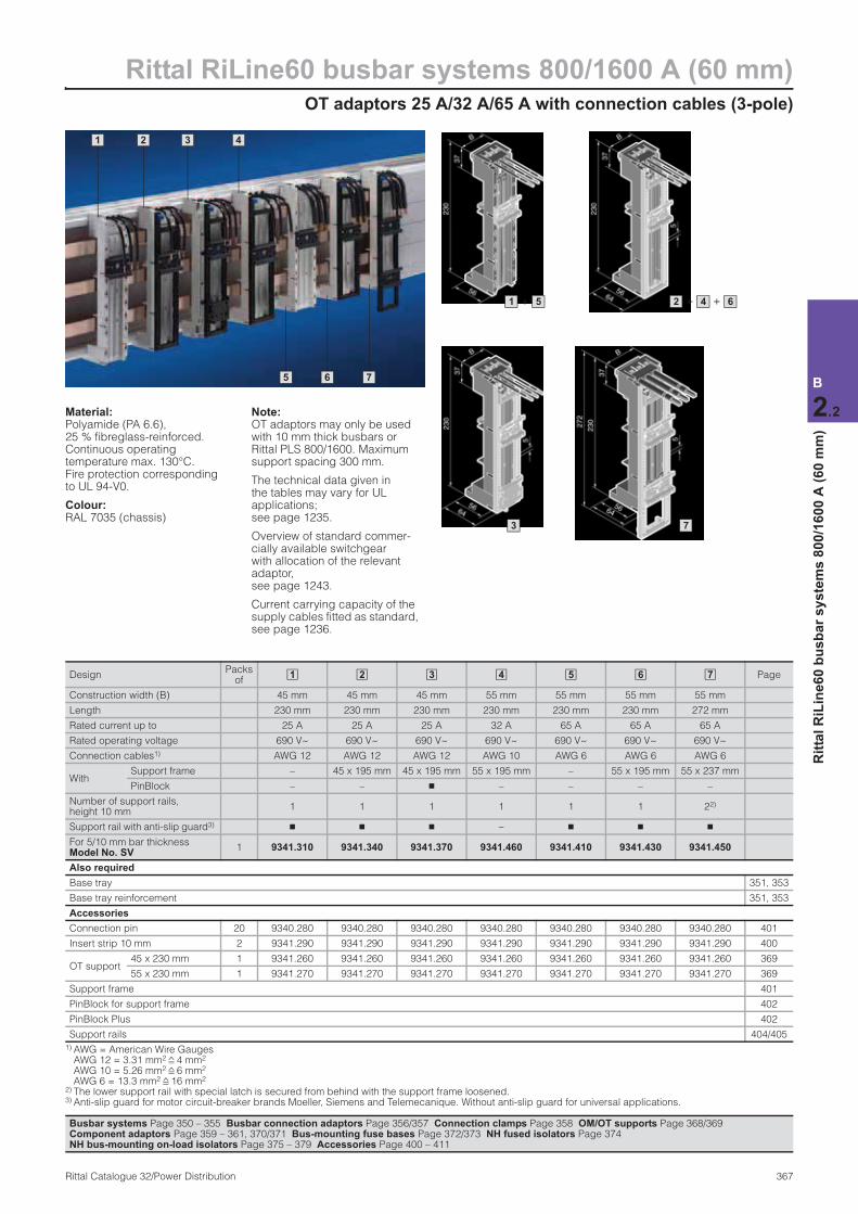
OT adaptors 25 A/32 A/65 A with connection cables (3-pole)
Rittal RiLine60 busbar systems 800/1600 A (60 mm)
367Rittal Catalogue 32/Power Distribution
B
2.2
Rit
tal
RiL
ine
60
bu
sb
ar
sy
ste
ms
80
0/1
60
0 A
(6
0 m
m)
1 2 3 4
5 6 7
Material:Polyamide (PA 6.6), 25 % fibreglass-reinforced. Continuous operating temperature max. 130°C. Fire protection corresponding to UL 94-V0.
Colour:RAL 7035 (chassis)
Note:OT adaptors may only be used with 10 mm thick busbars or Rittal PLS 800/1600. Maximum support spacing 300 mm.
The technical data given in the tables may vary for UL applications; see page 1235.
Overview of standard commer-cially available switchgear with allocation of the relevant adaptor, see page 1243.
Current carrying capacity of the supply cables fitted as standard, see page 1236.
DesignPacks
of Page
Construction width (B) 45 mm 45 mm 45 mm 55 mm 55 mm 55 mm 55 mm
Length 230 mm 230 mm 230 mm 230 mm 230 mm 230 mm 272 mm
Rated current up to 25 A 25 A 25 A 32 A 65 A 65 A 65 A
Rated operating voltage 690 V~ 690 V~ 690 V~ 690 V~ 690 V~ 690 V~ 690 V~
Connection cables1) AWG 12 AWG 12 AWG 12 AWG 10 AWG 6 AWG 6 AWG 6
With Support frame – 45 x 195 mm 45 x 195 mm 55 x 195 mm – 55 x 195 mm 55 x 237 mm
PinBlock – – n – – – –
Number of support rails, height 10 mm
1 1 1 1 1 1 22)
Support rail with anti-slip guard3) n n n – n n n
For 5/10 mm bar thickness Model No. SV
1 9341.310 9341.340 9341.370 9341.460 9341.410 9341.430 9341.450
Also required
Base tray 351, 353
Base tray reinforcement 351, 353
Accessories
Connection pin 20 9340.280 9340.280 9340.280 9340.280 9340.280 9340.280 9340.280 401
Insert strip 10 mm 2 9341.290 9341.290 9341.290 9341.290 9341.290 9341.290 9341.290 400
OT support45 x 230 mm 1 9341.260 9341.260 9341.260 9341.260 9341.260 9341.260 9341.260 369
55 x 230 mm 1 9341.270 9341.270 9341.270 9341.270 9341.270 9341.270 9341.270 369
Support frame 401
PinBlock for support frame 402
PinBlock Plus 402
Support rails 404/405
1) AWG = American Wire GaugesAWG 12 = 3.31 mm2 4 mm2 AWG 10 = 5.26 mm2 6 mm2 AWG 6 = 13.3 mm2 16 mm2
2) The lower support rail with special latch is secured from behind with the support frame loosened. 3) Anti-slip guard for motor circuit-breaker brands Moeller, Siemens and Telemecanique. Without anti-slip guard for universal applications.
1 2 3 4 5 6 7
Busbar systems Page 350 – 355 Busbar connection adaptors Page 356/357 Connection clamps Page 358 OM/OT supports Page 368/369 Component adaptors Page 359 – 361, 370/371 Bus-mounting fuse bases Page 372/373 NH fused isolators Page 374 NH bus-mounting on-load isolators Page 375 – 379 Accessories Page 400 – 411
+1 5 + +2 4 6
3 7

Rittal RiLine60 busbar systems 800/1600 A (60 mm)OM supports without contact system (3-pole)
368 Rittal Catalogue 32/Power Distribution
B
2.2
Rit
tal
RiL
ine
60
bu
sb
ar
sy
ste
ms
80
0/1
60
0 A
(6
0 m
m)
1 2
Material:Polyamide (PA 6.6), 25 % fibreglass-reinforced. Continuous operating temperature max. 130°C. Fire protection corresponding to UL 94-V0.
Colour:RAL 7035 (chassis)
Note:Suitable for use in UL applications.
Design Packs of Page
Construction width 45 mm 55 mm
Length 208 mm 272 mm
With
Support frame 45 x 170 mm 55 x 237 mm
Support frame supports – n
PinBlock n –
Number of support rails, height 10 mm – 11)
For 5/10 mm bar thickness Model No. SV
1 9340.260 9340.270
Accessories
Connection pin 20 9340.280 9340.280 401
Insert strip 10 mm 2 9340.290 9340.290 400
Support frame 401
PinBlock for support frame 402
PinBlock Plus 402
Support rails 404/405
1) The support rail with special latch is attached from the rear with the support frame loosened.
1 2
Busbar systems Page 350 – 355 Busbar connection adaptors Page 356/357 Connection clamps Page 358 OM/OT adaptors Page 362 – 367 Component adaptors Page 359 – 361, 370/371 Bus-mounting fuse bases Page 372/373 NH fused isolators Page 374 NH bus-mounting on-load isolators Page 375 – 379 Accessories Page 400 – 411
1 2
OT supports without contact system (3-pole)
Rittal RiLine60 busbar systems 800/1600 A (60 mm)
369Rittal Catalogue 32/Power Distribution
B
2.2
Rit
tal
RiL
ine
60
bu
sb
ar
sy
ste
ms
80
0/1
60
0 A
(6
0 m
m)
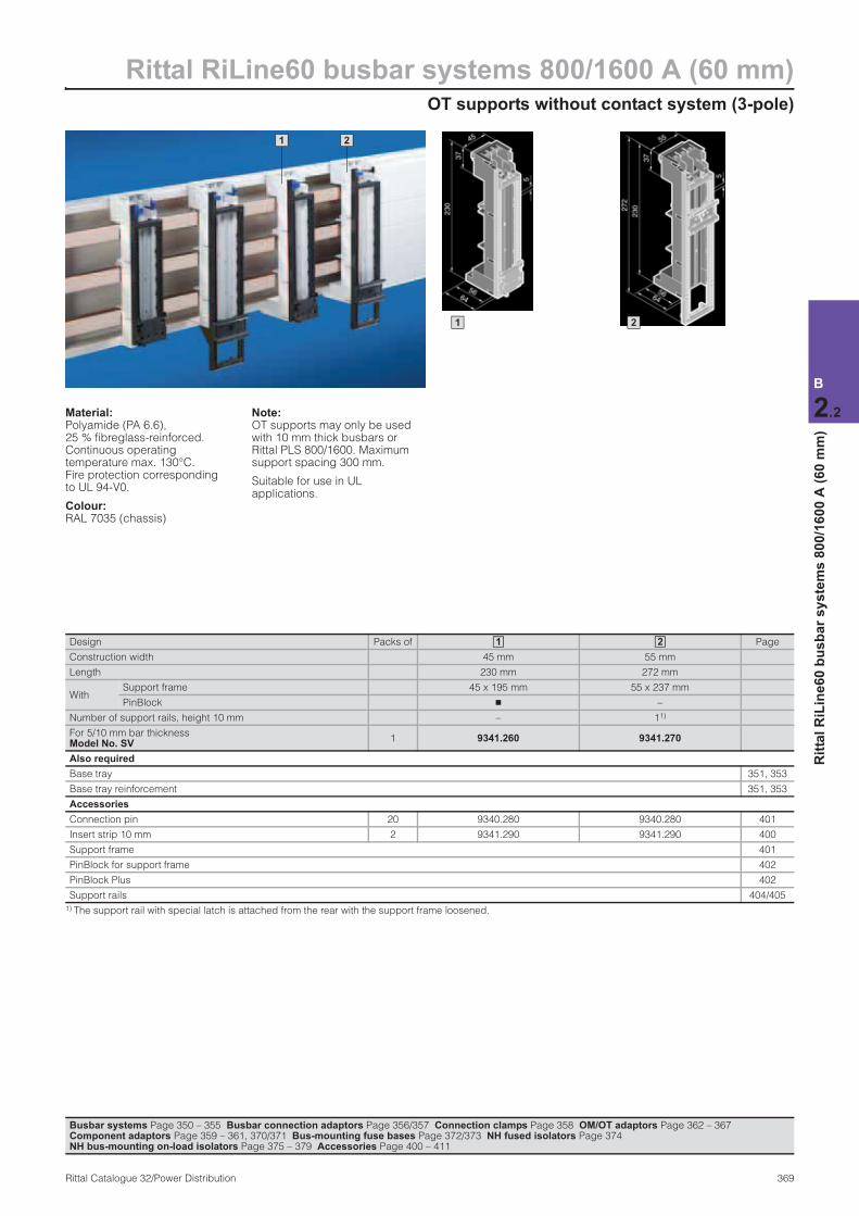
1 2
Material:Polyamide (PA 6.6), 25 % fibreglass-reinforced. Continuous operating temperature max. 130°C. Fire protection corresponding to UL 94-V0.
Colour:RAL 7035 (chassis)
Note:OT supports may only be used with 10 mm thick busbars or Rittal PLS 800/1600. Maximum support spacing 300 mm.
Suitable for use in UL applications.
Design Packs of Page
Construction width 45 mm 55 mm
Length 230 mm 272 mm
WithSupport frame 45 x 195 mm 55 x 237 mm
PinBlock n –
Number of support rails, height 10 mm – 11)
For 5/10 mm bar thickness Model No. SV
1 9341.260 9341.270
Also required
Base tray 351, 353
Base tray reinforcement 351, 353
Accessories
Connection pin 20 9340.280 9340.280 401
Insert strip 10 mm 2 9341.290 9341.290 400
Support frame 401
PinBlock for support frame 402
PinBlock Plus 402
Support rails 404/405
1) The support rail with special latch is attached from the rear with the support frame loosened.
1 2
Busbar systems Page 350 – 355 Busbar connection adaptors Page 356/357 Connection clamps Page 358 OM/OT adaptors Page 362 – 367 Component adaptors Page 359 – 361, 370/371 Bus-mounting fuse bases Page 372/373 NH fused isolators Page 374 NH bus-mounting on-load isolators Page 375 – 379 Accessories Page 400 – 411
1 2
Rittal RiLine60 busbar systems 800/1600 A (60 mm)Component adaptors 100 A/circuit-breaker component adaptors 125 A, 160 A (3-pole)
370 Rittal Catalogue 32/Power Distribution
B
2.2
Rit
tal
RiL
ine
60
bu
sb
ar
sy
ste
ms
80
0/1
60
0 A
(6
0 m
m)
1 2 3 2 3
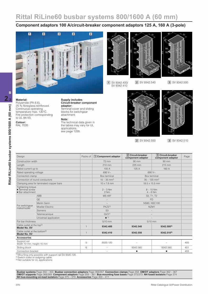
Material:Polyamide (PA 6.6), 25 % fibreglass-reinforced. Continuous operating temperature max. 130°C. Fire protection corresponding to UL 94-V0.
Colour:RAL 7035
Supply includes Circuit-breaker component adaptor: Terminal cover and sliding blocks for switchgear attachment.
Note:The technical data given in the tables may vary for UL applications; see page 1235.
Design Packs of Component adaptor Circuit-breaker
component adaptor Circuit-breaker
component adaptor Page
Construction width 72 mm 90 mm 90 mm
Length 210 mm 225 mm 215 mm
Rated current up to 100 A 125 A 160 A
Rated operating voltage 690 V~ 690 V~
Connection clamp Box terminal Box terminal
Connection of round conductors 10 – 35 mm2 35 – 120 mm2
Clamping area for laminated copper bars 10 x 7.8 mm 18.5 x 15.5 mm
Tightening torque ● Terminal screw ● Bar attachment
2 – 3 Nm 2 Nm
8 – 10 Nm 4 – 6 Nm
For switchgear make/model
ABB MS 497 S2, T1, T2
GE – FD
Merlin Gerin – NS80, NSC100
Moeller Electric PKZ21) NZM1
Siemens S3 –
Telemecanique GV31) –
Universal application n 1) –
For bar thickness 5/10 mm 5/10 mm
Cable outlet at the top2) Model No. SV
1 9342.400 9342.540 9342.5003)
Cable outlet at the bottom2) Model No. SV
1 9342.410 9342.550 9342.5103)
Accessories
Support rail Width 72 mm, height 15 mm
5 9320.120 – – 405
Sliding block 6 – 9342.560 9342.560 401
Connection bracket – n n 403
1) Mounting only possible with support rail SV 9320.120. 2) Switch outlet or outgoing cable. 3) Not suitable for UL applications.
12 3
Busbar systems Page 350 – 355 Busbar connection adaptors Page 356/357 Connection clamps Page 358 OM/OT adaptors Page 362 – 367 OM/OT supports Page 368/369 Component adaptors Page 359 – 361 Bus-mounting fuse bases Page 372/373 NH fused isolators Page 374 NH bus-mounting on-load isolators Page 375 – 379 Accessories Page 400 – 411
SV 9342.400/SV 9342.410
1 SV 9342.540 2
SV 9342.550 2
SV 9342.500 3
SV 9342.510 3
Circuit-breaker component adaptors 250 A/630 A (3-pole)
Rittal RiLine60 busbar systems 800/1600 A (60 mm)
371Rittal Catalogue 32/Power Distribution
B
2.2
Rit
tal
RiL
ine
60
bu
sb
ar
sy
ste
ms
80
0/1
60
0 A
(6
0 m
m)
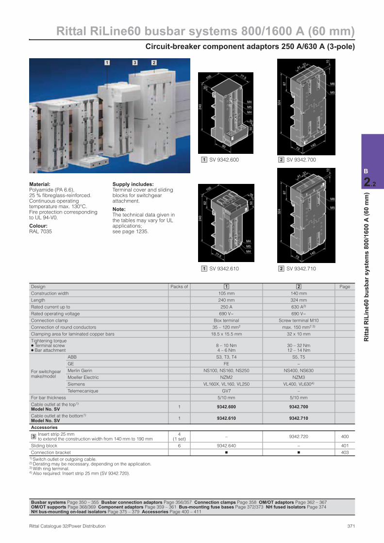
1 2 3
Material:Polyamide (PA 6.6), 25 % fibreglass-reinforced. Continuous operating temperature max. 130°C. Fire protection corresponding to UL 94-V0.
Colour:RAL 7035
Supply includes:Terminal cover and sliding blocks for switchgear attachment.
Note:The technical data given in the tables may vary for UL applications; see page 1235.
Design Packs of Page
Construction width 105 mm 140 mm
Length 240 mm 324 mm
Rated current up to 250 A 630 A2)
Rated operating voltage 690 V~ 690 V~
Connection clamp Box terminal Screw terminal M10
Connection of round conductors 35 – 120 mm2 max. 150 mm2 3)
Clamping area for laminated copper bars 18.5 x 15.5 mm 32 x 10 mm
Tightening torque ● Terminal screw ● Bar attachment
8 – 10 Nm 4 – 6 Nm
30 – 32 Nm 12 – 14 Nm
For switchgear make/model
ABB S3, T3, T4 S5, T5
GE FE –
Merlin Gerin NS100, NS160, NS250 NS400, NS630
Moeller Electric NZM2 NZM3
Siemens VL160X, VL160, VL250 VL400, VL6304)
Telemecanique GV7 –
For bar thickness 5/10 mm 5/10 mm
Cable outlet at the top1) Model No. SV
1 9342.600 9342.700
Cable outlet at the bottom1) Model No. SV
1 9342.610 9342.710
Accessories
Insert strip 25 mm to extend the construction width from 140 mm to 190 mm
4 (1 set)
– 9342.720 400
Sliding block 6 9342.640 – 401
Connection bracket n n 403
1) Switch outlet or outgoing cable. 2) Derating may be necessary, depending on the application.3) With ring terminal. 4) Also required: Insert strip 25 mm (SV 9342.720).
1 2
3
SV 9342.600 1 SV 9342.700 2
SV 9342.710 2 SV 9342.610 1
Busbar systems Page 350 – 355 Busbar connection adaptors Page 356/357 Connection clamps Page 358 OM/OT adaptors Page 362 – 367 OM/OT supports Page 368/369 Component adaptors Page 359 – 361 Bus-mounting fuse bases Page 372/373 NH fused isolators Page 374 NH bus-mounting on-load isolators Page 375 – 379 Accessories Page 400 – 411
Rittal RiLine60 busbar systems 800/1600 A (60 mm)Bus-mounting fuse bases (3-pole)
372 Rittal Catalogue 32/Power Distribution
B
2.2
Rit
tal
RiL
ine
60
bu
sb
ar
sy
ste
ms
80
0/1
60
0 A
(6
0 m
m)
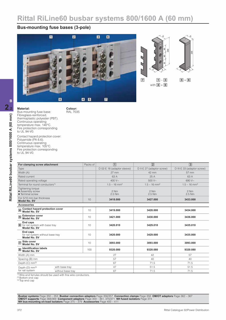
Material:Bus-mounting fuse base: Fibreglass-reinforced, thermoplastic polyester (PBT). Continuous operating temperature max. 140°C. Fire protection corresponding to UL 94-V0.
Contact hazard protection cover: Polyamide (PA 6.6). Continuous operating temperature max. 105°C. Fire protection corresponding to UL 94-V0.
Colour:RAL 7035
For clamping screw attachment Packs of
Type D 02-E 18 (adaptor sleeve) D II-E 27 (adaptor screw) D III-E 33 (adaptor screw)
Width (A) 27 mm 42 mm 57 mm
Rated current 63 A 25 A 63 A
Rated operating voltage 400 V~ 500 V~ 690 V~
Terminal for round conductors1) 1.5 – 16 mm2 1.5 – 16 mm2 1.5 – 16 mm2
Tightening torque ● Assembly screw ● Terminal screw
2 Nm 2.5 Nm
2 Nm 2.5 Nm
2 Nm 2.5 Nm
For 5/10 mm bar thicknessModel No. SV
10 3418.000 3427.000 3433.000
Accessories
Contact hazard protection cover Model No. SV
10 3419.000 3428.000 3434.000
Extension cover Model No. SV
10 3421.000 3430.000 3436.000
End caps for rail system with base tray Model No. SV
10 3420.010 3429.010 3435.010
End caps for rail system without base tray Model No. SV
10 3420.000 3429.000 3435.000
Side cover Model No. SV
10 3093.000 3093.000 3093.000
Identification labels Model No. SV
100 9320.080 9320.080 9320.080
Width (A) mm 27 42 57
Spacing (B) mm 57 40 40
Depth (C) mm2) 67 71.5 71.5
Depth (D) mm3) for rail system
with base tray 47 51.5 51.5
without base tray 67 71.5 71.5
1) Wire end ferrules should be used with fine wire conductors. 2) Bottom end cap 3) Top end cap
1 2 3
4
5
6
7
8
Busbar systems Page 350 – 353 Busbar connection adaptors Page 356/357 Connection clamps Page 358 OM/OT adaptors Page 362 – 367 OM/OT supports Page 368/369 Component adaptors Page 359 – 361, 370/371 NH fused isolators Page 374 NH bus-mounting on-load isolators Page 375 – 379 Accessories Page 400 – 411
7
1 2 6 3
8 4 5
230
A
B60
60
C
D
AC
230
D
7 – 1 3 + 5 6
with + 4 6

Bus-mounting fuse bases (3-pole)
Rittal RiLine60 busbar systems 800/1600 A (60 mm)
373Rittal Catalogue 32/Power Distribution
B
2.2
Rit
tal
RiL
ine
60
bu
sb
ar
sy
ste
ms
80
0/1
60
0 A
(6
0 m
m)
Material:Bus-mounting fuse base: Fibreglass-reinforced, thermoplastic polyester (PBT).Continuous operating temperature max. 140°C. Fire protection corresponding to UL 94-V0.
Contact hazard protection cover: Polyamide (PA 6.6). Continuous operating temperature: max. 105°C. Fire protection corresponding to UL 94-V0.
Colour:RAL 7035
For snap-on mounting Packs of
Type D 02-E 18 (adaptor sleeve) D II-E 27 (gauge ring) D III-E 33 (gauge ring)
Width (A) 36 mm 42 mm 57 mm
Rated current 63 A 25 A 63 A
Rated operating voltage 400 V~ 500 V~ 690 V~
Terminal for round conductors1) 1.5 – 16 mm2 1.5 – 16 mm2 1.5 – 16 mm2
Tightening torque ● Terminal screw 2.5 Nm 2.5 Nm 2.5 Nm
For 5 mm bar thicknessModel No. SV
10 3422.000 3520.000 3530.000
For 10 mm bar thicknessModel No. SV
10 3423.000 3521.000 3531.000
Accessories
Contact hazard protection cover Model No. SV
10 3424.000 3428.000 3434.000
Extension cover Model No. SV
10 – 3430.000 3436.000
End caps for rail system with base tray Model No. SV
10 3425.010 3429.010 3435.010
End caps for rail system without base tray Model No. SV
10 3425.000 3429.000 3435.000
Side cover Model No. SV
10 3093.000 3093.000 3093.000
Identification labels Model No. SV
100 9320.080 9320.080 9320.080
Width (A) mm 36 42 57
Spacing (B) mm 57 40 40
Depth (C) mm2) 67 71.5 71.5
Depth (D) mm3) for rail system
with base tray 47 51.5 51.5
without base tray 67 71.5 71.5
1) Wire end ferrules should be used with fine wire conductors. 2) Bottom end cap 3) Top end cap
1 2 3
4
5
6
7
8
Busbar systems Page 350 – 353 Busbar connection adaptors Page 356/357 Connection clamps Page 358 OM/OT adaptors Page 362 – 367 OM/OT supports Page 368/369 Component adaptors Page 359 – 361, 370/371 NH fused isolators Page 374 NH bus-mounting on-load isolators Page 375 – 379 Accessories Page 400 – 411
7
1 2 3
8 4 5
6
7 + 5 6– 1 3
with + 4 6
230
A
B60
60
C
D
AC
230
D

Rittal RiLine60 busbar systems 800/1600 A (60 mm)NH fused isolators, size 00 (3-pole)
374 Rittal Catalogue 32/Power Distribution
B
2.2
Rit
tal
RiL
ine
60
bu
sb
ar
sy
ste
ms
80
0/1
60
0 A
(6
0 m
m)
1 2
50
403.4
134 – 191*
300
75
134 – 191*
50
403
.4
300
75
* Off-load position
1 2
Busbar systems Page 350 – 353 Busbar connection adaptors Page 356/357 Connection clamps Page 358 OM/OT adaptors Page 362 – 367 OM/OT supports Page 368/369 Component adaptors Page 359 – 361, 370/371 Bus-mounting fuse bases Page 372/373NH bus-mounting on-load isolators Page 375 – 379 Accessories Page 400 – 411
Material:Cover, strip chassis: Fibreglass-reinforced polyamide Contact tracks: Silver-plated hard copper
Technical information, see page 1244.
Design Packs of Page
Size Size 00 Size 00
Rated current 160 A 160 A
Rated operating voltage 690 V~ 690 V~
Cable outlet top bottom
Type of connection Screw M8 Screw M8
Tightening torque ● Assembly screw ● Terminal screw
6 Nm 14 Nm
6 Nm 14 Nm
For bar thickness 5/10 mm 5/10 mm
Model No. SV 1 3591.020 3591.030
Accessories
Side panel 2 9341.230 9341.230 405
Identification label support 6 3595.010 3595.010 406
Micro-switch 5 3071.000 3071.000 406
Lug terminal connection parts 1 set 3592.020 3592.020 407
Clamp-type terminal connection 1 set 3592.010 3592.010 407
1 2
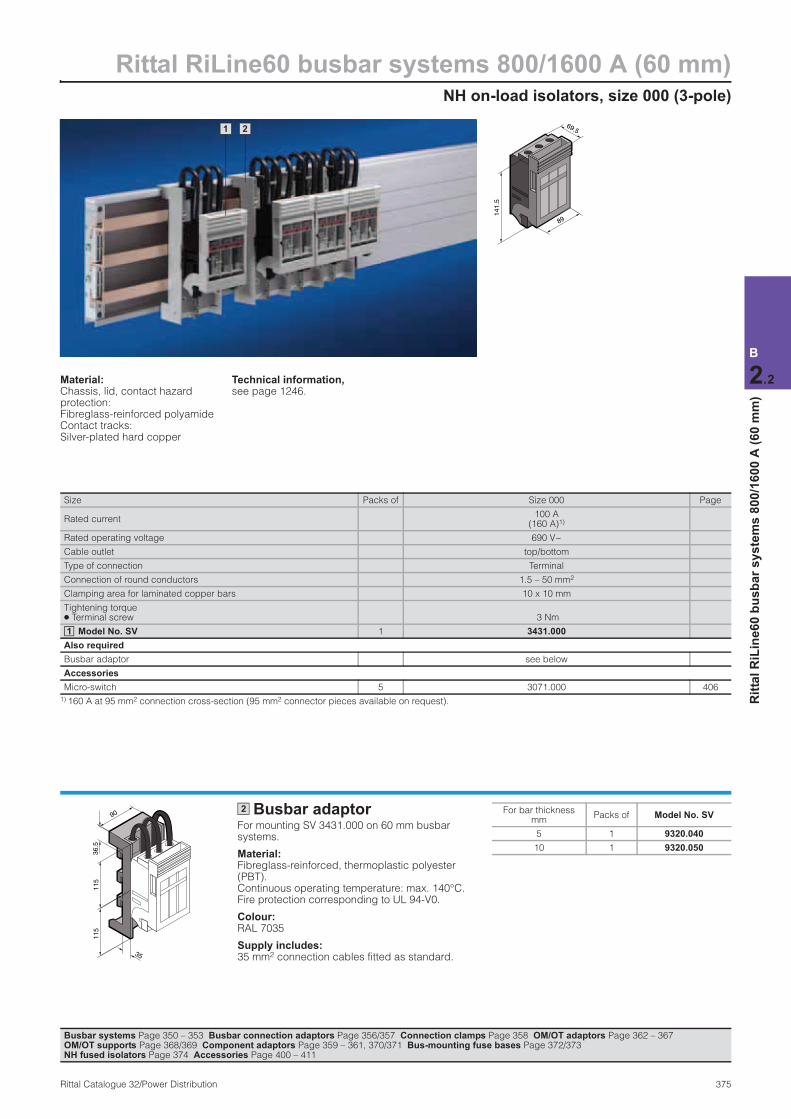
NH on-load isolators, size 000 (3-pole)
Rittal RiLine60 busbar systems 800/1600 A (60 mm)
375Rittal Catalogue 32/Power Distribution
B
2.2
Rit
tal
RiL
ine
60
bu
sb
ar
sy
ste
ms
80
0/1
60
0 A
(6
0 m
m)
1 2 69.5
141
.5
89
Busbar adaptorFor mounting SV 3431.000 on 60 mm busbar systems.
Material:Fibreglass-reinforced, thermoplastic polyester (PBT). Continuous operating temperature: max. 140°C. Fire protection corresponding to UL 94-V0.
Colour:RAL 7035
Supply includes:35 mm2 connection cables fitted as standard.
90
35
115
115
36.5
2 For bar thickness mm
Packs of Model No. SV
5 1 9320.040
10 1 9320.050
Busbar systems Page 350 – 353 Busbar connection adaptors Page 356/357 Connection clamps Page 358 OM/OT adaptors Page 362 – 367 OM/OT supports Page 368/369 Component adaptors Page 359 – 361, 370/371 Bus-mounting fuse bases Page 372/373NH fused isolators Page 374 Accessories Page 400 – 411
Material:Chassis, lid, contact hazard protection: Fibreglass-reinforced polyamide Contact tracks: Silver-plated hard copper
Technical information, see page 1246.
Size Packs of Size 000 Page
Rated current100 A
(160 A)1)
Rated operating voltage 690 V~
Cable outlet top/bottom
Type of connection Terminal
Connection of round conductors 1.5 – 50 mm2
Clamping area for laminated copper bars 10 x 10 mm
Tightening torque ● Terminal screw 3 Nm
Model No. SV 1 3431.000
Also required
Busbar adaptor see below
Accessories
Micro-switch 5 3071.000 406
1) 160 A at 95 mm2 connection cross-section (95 mm2 connector pieces available on request).
1
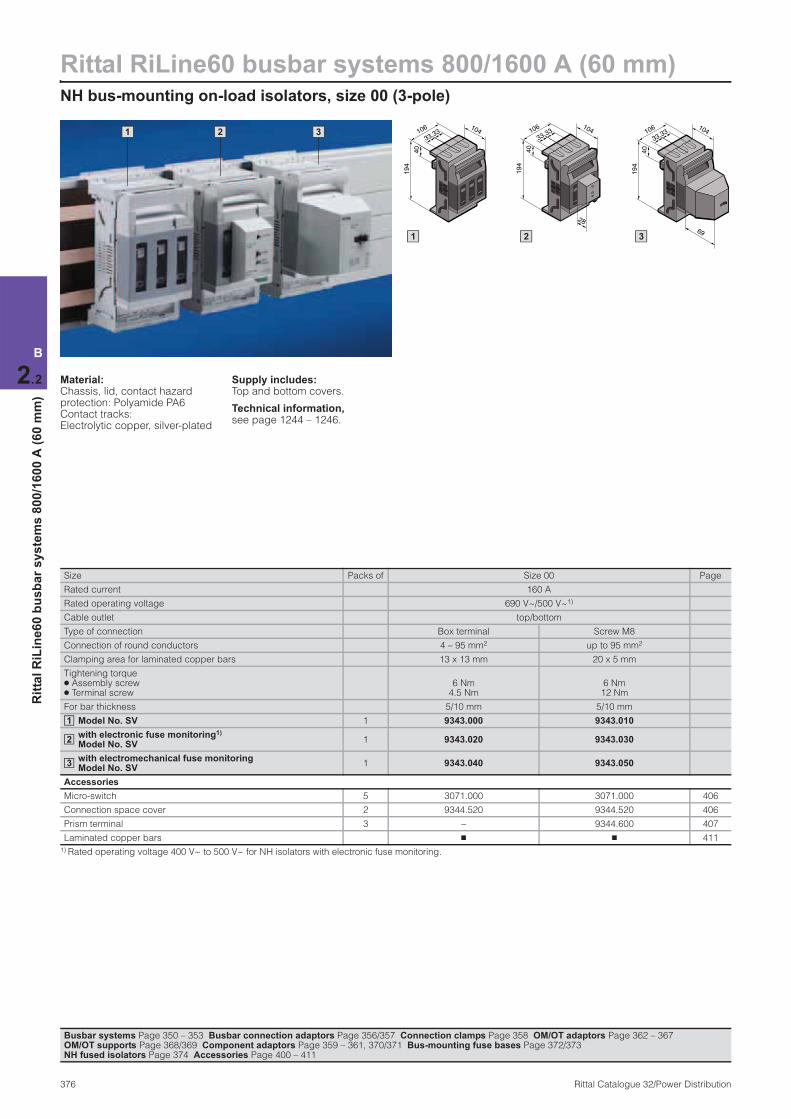
Rittal RiLine60 busbar systems 800/1600 A (60 mm)NH bus-mounting on-load isolators, size 00 (3-pole)
376 Rittal Catalogue 32/Power Distribution
B
2.2
Rit
tal
RiL
ine
60
bu
sb
ar
sy
ste
ms
80
0/1
60
0 A
(6
0 m
m)
1 2 3 106 104
40
194
3333 106 104
3333
28
40
194
106 104
3333
69
40
194
1 2 3
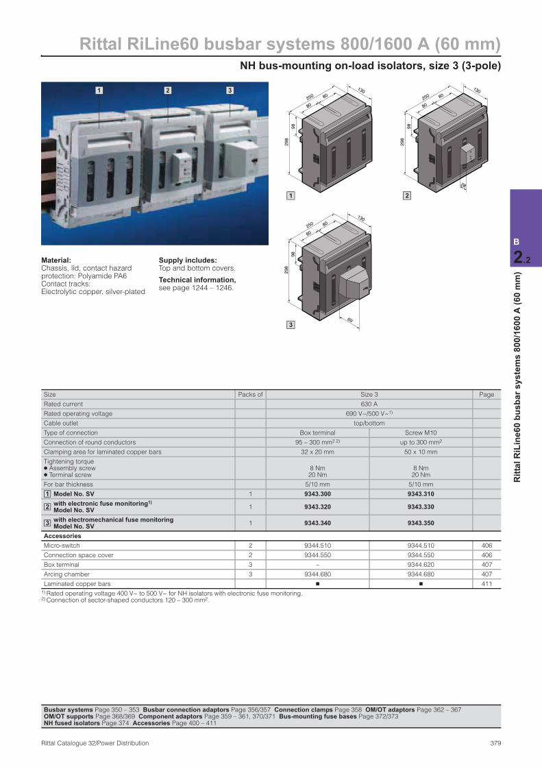
Material:Chassis, lid, contact hazard protection: Polyamide PA6 Contact tracks: Electrolytic copper, silver-plated
Supply includes:Top and bottom covers.
Technical information, see page 1244 – 1246.
Size Packs of Size 00 Page
Rated current 160 A
Rated operating voltage 690 V~/500 V~1)
Cable outlet top/bottom
Type of connection Box terminal Screw M8
Connection of round conductors 4 – 95 mm2 up to 95 mm2
Clamping area for laminated copper bars 13 x 13 mm 20 x 5 mm
Tightening torque ● Assembly screw ● Terminal screw
6 Nm 4.5 Nm
6 Nm 12 Nm
For bar thickness 5/10 mm 5/10 mm
Model No. SV 1 9343.000 9343.010
with electronic fuse monitoring1) Model No. SV
1 9343.020 9343.030
with electromechanical fuse monitoring Model No. SV
1 9343.040 9343.050
Accessories
Micro-switch 5 3071.000 3071.000 406
Connection space cover 2 9344.520 9344.520 406
Prism terminal 3 – 9344.600 407
Laminated copper bars n n 411
1) Rated operating voltage 400 V~ to 500 V~ for NH isolators with electronic fuse monitoring.
1
2
3
Busbar systems Page 350 – 353 Busbar connection adaptors Page 356/357 Connection clamps Page 358 OM/OT adaptors Page 362 – 367 OM/OT supports Page 368/369 Component adaptors Page 359 – 361, 370/371 Bus-mounting fuse bases Page 372/373NH fused isolators Page 374 Accessories Page 400 – 411
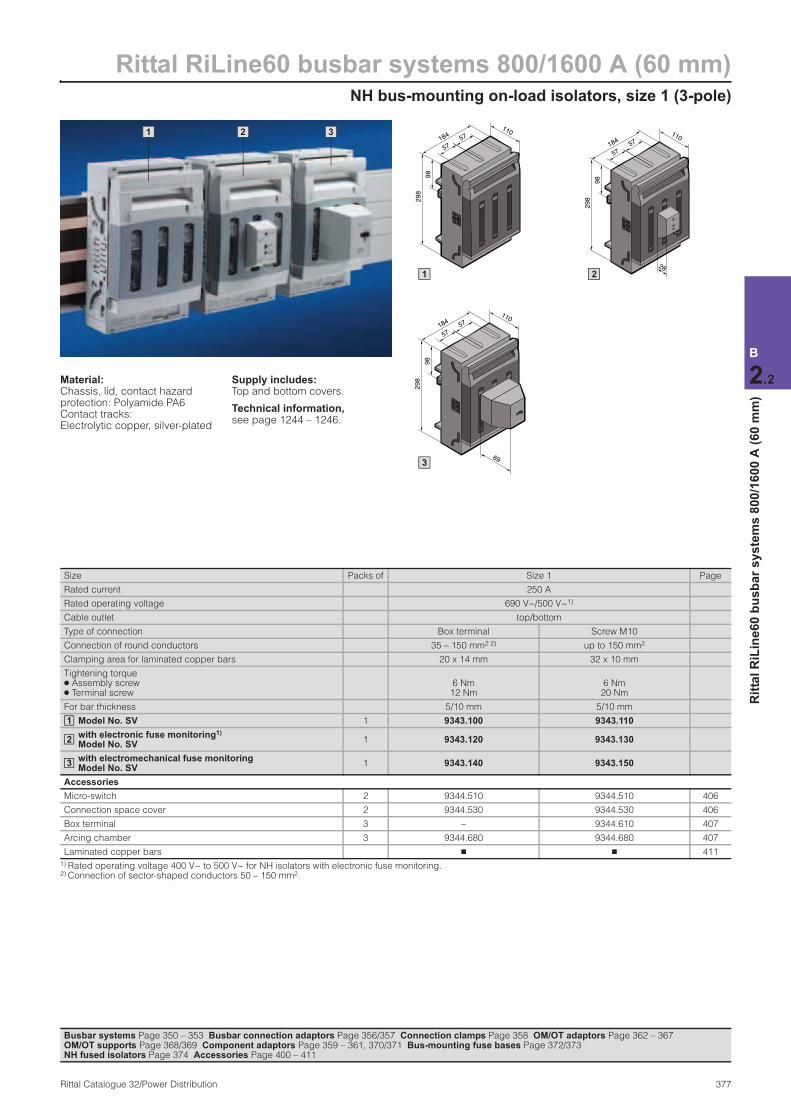
NH bus-mounting on-load isolators, size 1 (3-pole)
Rittal RiLine60 busbar systems 800/1600 A (60 mm)
377Rittal Catalogue 32/Power Distribution
B
2.2
Rit
tal
RiL
ine
60
bu
sb
ar
sy
ste
ms
80
0/1
60
0 A
(6
0 m
m)
1 2 3 184
110
57
57
98
298
184
110
298
57
57
28
98
184
110
298
57
57
69
98
1 2
3
Material:Chassis, lid, contact hazard protection: Polyamide PA6 Contact tracks: Electrolytic copper, silver-plated
Supply includes:Top and bottom covers.
Technical information, see page 1244 – 1246.
Size Packs of Size 1 Page
Rated current 250 A
Rated operating voltage 690 V~/500 V~1)
Cable outlet top/bottom
Type of connection Box terminal Screw M10
Connection of round conductors 35 – 150 mm2 2) up to 150 mm2
Clamping area for laminated copper bars 20 x 14 mm 32 x 10 mm
Tightening torque ● Assembly screw ● Terminal screw
6 Nm 12 Nm
6 Nm 20 Nm
For bar thickness 5/10 mm 5/10 mm
Model No. SV 1 9343.100 9343.110
with electronic fuse monitoring1) Model No. SV
1 9343.120 9343.130
with electromechanical fuse monitoring Model No. SV
1 9343.140 9343.150
Accessories
Micro-switch 2 9344.510 9344.510 406
Connection space cover 2 9344.530 9344.530 406
Box terminal 3 – 9344.610 407
Arcing chamber 3 9344.680 9344.680 407
Laminated copper bars n n 411
1) Rated operating voltage 400 V~ to 500 V~ for NH isolators with electronic fuse monitoring. 2) Connection of sector-shaped conductors 50 – 150 mm2.
1
2
3
Busbar systems Page 350 – 353 Busbar connection adaptors Page 356/357 Connection clamps Page 358 OM/OT adaptors Page 362 – 367 OM/OT supports Page 368/369 Component adaptors Page 359 – 361, 370/371 Bus-mounting fuse bases Page 372/373NH fused isolators Page 374 Accessories Page 400 – 411
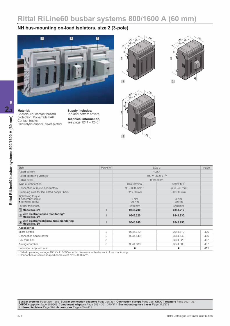
Rittal RiLine60 busbar systems 800/1600 A (60 mm)NH bus-mounting on-load isolators, size 2 (3-pole)
378 Rittal Catalogue 32/Power Distribution
B
2.2
Rit
tal
RiL
ine
60
bu
sb
ar
sy
ste
ms
80
0/1
60
0 A
(6
0 m
m)
1 2 3 210
130
65
65
298
98
210
130
65
65
28
298
98
210
130
65
65
69
298
98
1 2
3
Material:Chassis, lid, contact hazard protection: Polyamide PA6 Contact tracks: Electrolytic copper, silver-plated
Supply includes:Top and bottom covers.
Technical information, see page 1244 – 1246.
Size Packs of Size 2 Page
Rated current 400 A
Rated operating voltage 690 V~/500 V~1)
Cable outlet top/bottom
Type of connection Box terminal Screw M10
Connection of round conductors 95 – 300 mm2 2) up to 240 mm2
Clamping area for laminated copper bars 32 x 20 mm 50 x 10 mm
Tightening torque ● Assembly screw ● Terminal screw
8 Nm 20 Nm
8 Nm 20 Nm
For bar thickness 5/10 mm 5/10 mm
Model No. SV 1 9343.200 9343.210
with electronic fuse monitoring1) Model No. SV
1 9343.220 9343.230
with electromechanical fuse monitoring Model No. SV
1 9343.240 9343.250
Accessories
Micro-switch 2 9344.510 9344.510 406
Connection space cover 2 9344.540 9344.540 406
Box terminal 3 – 9344.620 407
Arcing chamber 3 9344.680 9344.680 407
Laminated copper bars n n 411
1) Rated operating voltage 400 V~ to 500 V~ for NH isolators with electronic fuse monitoring. 2) Connection of sector-shaped conductors 120 – 300 mm2.
1
2
3
Busbar systems Page 350 – 353 Busbar connection adaptors Page 356/357 Connection clamps Page 358 OM/OT adaptors Page 362 – 367 OM/OT supports Page 368/369 Component adaptors Page 359 – 361, 370/371 Bus-mounting fuse bases Page 372/373NH fused isolators Page 374 Accessories Page 400 – 411
NH bus-mounting on-load isolators, size 3 (3-pole)
Rittal RiLine60 busbar systems 800/1600 A (60 mm)
379Rittal Catalogue 32/Power Distribution
B
2.2
Rit
tal
RiL
ine
60
bu
sb
ar
sy
ste
ms
80
0/1
60
0 A
(6
0 m
m)
1 2 3
250
130
80
80
298
98
250
130
80
80
28
298
98
250
130
80
80
69
298
98
1 2
3
Material:Chassis, lid, contact hazard protection: Polyamide PA6 Contact tracks: Electrolytic copper, silver-plated
Supply includes:Top and bottom covers.
Technical information, see page 1244 – 1246.
Size Packs of Size 3 Page
Rated current 630 A
Rated operating voltage 690 V~/500 V~1)
Cable outlet top/bottom
Type of connection Box terminal Screw M10
Connection of round conductors 95 – 300 mm2 2) up to 300 mm2
Clamping area for laminated copper bars 32 x 20 mm 50 x 10 mm
Tightening torque ● Assembly screw ● Terminal screw
8 Nm 20 Nm
8 Nm 20 Nm
For bar thickness 5/10 mm 5/10 mm
Model No. SV 1 9343.300 9343.310
with electronic fuse monitoring1) Model No. SV
1 9343.320 9343.330
with electromechanical fuse monitoring Model No. SV
1 9343.340 9343.350
Accessories
Micro-switch 2 9344.510 9344.510 406
Connection space cover 2 9344.550 9344.550 406
Box terminal 3 – 9344.620 407
Arcing chamber 3 9344.680 9344.680 407
Laminated copper bars n n 411
1) Rated operating voltage 400 V~ to 500 V~ for NH isolators with electronic fuse monitoring. 2) Connection of sector-shaped conductors 120 – 300 mm2.
1
2
3
Busbar systems Page 350 – 353 Busbar connection adaptors Page 356/357 Connection clamps Page 358 OM/OT adaptors Page 362 – 367 OM/OT supports Page 368/369 Component adaptors Page 359 – 361, 370/371 Bus-mounting fuse bases Page 372/373NH fused isolators Page 374 Accessories Page 400 – 411
Rittal RiLine60 busbar systems 800 A (60 mm)Busbar supports (4-pole)
380 Rittal Catalogue 32/Power Distribution
B
2.2
Rit
tal
RiL
ine
60
bu
sb
ar
sy
ste
ms
80
0 A
(6
0 m
m)
1 2
4 5
3
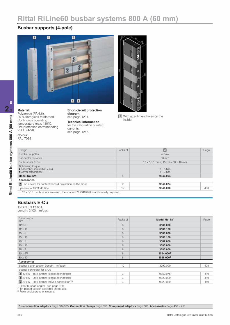
Material:Polyamide (PA 6.6), 25 % fibreglass-reinforced. Continuous operating temperature max. 130°C. Fire protection corresponding to UL 94-V0.
Colour:RAL 7035
Short-circuit protection diagram, see page 1231.
Technical information for the calculation of rated currents, see page 1247.
Design Packs of Page
Number of poles 4-pole
Bar centre distance 60 mm
For busbars E-Cu 12 x 5/10 mm1), 15 x 5 – 30 x 10 mm
Tightening torque ● Assembly screw (M5 x 25) ● Cover attachment
3 – 5 Nm1 – 3 Nm
Model No. SV 4 9340.004
Accessories
End covers for contact hazard protection on the sides 2 9340.074
Spacers for SV 9340.004 12 9340.090 400
1) If 12 x 5/10 mm busbars are used, the spacer SV 9340.090 is additionally required.
1
2
Busbars E-CuTo DIN EN 13 601. Length: 2400 mm/bar.
Dimensions mm
Packs of Model No. SV Page
12 x 5 6 3580.000
12 x 10 6 3580.100
15 x 5 6 3581.000
15 x 10 6 3581.100
20 x 5 6 3582.000
20 x 10 6 3585.000
25 x 5 6 3583.000
30 x 51) 6 3584.0002)
30 x 101) 6 3586.0002)
Accessories
Busbar cover section (length 1 m/each) 10 3092.000 408
Busbar connector for E-Cu
12 x 5 – 15 x 10 mm (single connection) 3 9350.075 410
20 x 5 – 30 x 10 mm (single connection) 3 9320.020 410
20 x 5 – 30 x 10 mm (bayed connection)3) 3 9320.030 410
1) Other busbar lengths, see page 409. 2) Tin-plated version available on request. 3) From enclosure to enclosure.
3
4
5
With attachment holes on the inside
1
Bus connection adaptors Page 384/385 Connection clamps Page 358 Component adaptors Page 386 Accessories Page 408 – 411

System components (4-pole)
Rittal RiLine60 busbar systems 800 A (60 mm)
381Rittal Catalogue 32/Power Distribution
B
2.2
Rit
tal
RiL
ine
60
bu
sb
ar
sy
ste
ms
80
0 A
(6
0 m
m)
Base trayFor rear contact hazard protection of the flat bar assembly.
Cover sectionMay be cut to length as required; for clip-on mounting to the base tray.
Base tray and cover section Material:Thermally modified hard PVC. Continuous operating temperature max. 91°C. Fire protection corresponding to UL 94-V0.
Colour:RAL 7035
Note:If the cover section is mounted from the front, the support panel (SV 9340.224) is needed for stability.
Length (L) mm Packs of Model No. SV
1100 2 9340.134
1
2
1
Length (L) mm Packs of Model No. SV
1100 2 9340.214
2
Support panel for cover section To prevent side access to the cover section. The support panel also provides additional stability.
Material:Polyamide (PA 6.6). Continuous operating temperature max. 105°C. Fire protection corresponding to UL 94-V0.
Colour:RAL 7035
Packs of Model No. SV
5 9340.224
Bus connection adaptors Page 384/385 Connection clamps Page 358 Component adaptors Page 386 Accessories Page 408 – 411

Rittal RiLine60 busbar systems 800/1600 A (60 mm)Busbar supports PLUS (4-pole)
382 Rittal Catalogue 32/Power Distribution
B
2.2
Rit
tal
RiL
ine
60
bu
sb
ar
sy
ste
ms
80
0/1
60
0 A
(6
0 m
m)
3 1 2 3
6 5 4
Material:Polyamide (PA 6.6), 25 % fibreglass-reinforced. Continuous operating temperature max. 130°C. Fire protection corresponding to UL 94-V0.
Colour:RAL 7035
Short-circuit protection diagram, see page 1231.
Technical information for the calculation of rated currents, see page 1249.
For system Packs of Rittal 30 x 10 PLUS Rittal PLS 1600 PLUS
Number of poles 4-pole 4-pole
Bar centre distance 60 mm 60 mm
Forbusbars E-Cu 30 x 10 mm n –
PLS special busbars (PLS 1600) – n
Tightening torque ● Assembly screw (M6 x 20) ● Cover attachment
3 – 5 Nm5 – 7 Nm
3 – 5 Nm5 – 7 Nm
Model No. SV 4 9342.014 9342.004
Accessories
End covers for contact hazard protection on the sides 2 9342.074 9342.074
1 2
3
Busbars made from E-Cu
Detailed drawing:SV 9661.300 to .380, see page 409.
For system Rittal 30 x 10 PLUS Rittal PLS 1600 PLUS Page
Size 30 x 10 mm –
Cross-section (bar thickness) – 900 mm2 (10 mm)1)
For enclosure width mm
Length mm
Packs ofModel No.
SVLength
mmPacks of
Model No. SV
3002) 265 2 9661.330 – – –
4002) 365 2 9661.340 – – –
6002) 565 2 9661.360 495 3 3527.000
8002) 765 2 9661.380 695 3 3528.000
10002) 965 2 9661.300 895 3 3528.010
12002) 1165 2 9661.320 1095 3 3529.000
Variable 2400 6 3586.000 2400 1 3516.000
Accessories
PLS busbar connector (single connection) – – – – 3 3514.000 410
PLS busbar connector (bayed connection)3) – – – – 3 3515.000 410
PLS expansion connectors4) – – – – 3 9320.070 410
Baying bracket for SV 9661.300 to .380 (bayed connection) 95 4 9661.350 409
Busbar connector for SV 3586.000Single connection – 3 9320.020 – – – 410
Baying connection3) – 3 9320.030 – – – 410
Busbar cover section 1000 10 3092.000 – – – 408
1) PLS special busbars (1600 A). To order tin-plated version, please add extension .2X0 to the Model No. Delivery times available on request. 2) For Rittal TS 8/ES enclosure systems.3) From enclosure to enclosure. 4) Two PLS rail connectors (single connection) are required to fit one expansion connector.
4
5
6
Rittal 30 x 10 PLUS1 Rittal PLS 1600 PLUS 2
Bus connection adaptors Page 384/385 Connection clamps Page 358 Component adaptors Page 386 Accessories Page 408 – 411
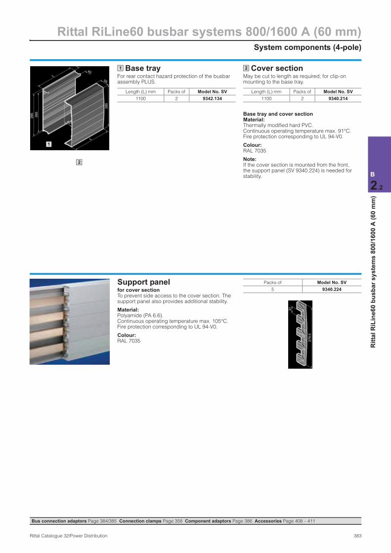
System components (4-pole)
Rittal RiLine60 busbar systems 800/1600 A (60 mm)
383Rittal Catalogue 32/Power Distribution
B
2.2
Rit
tal
RiL
ine
60
bu
sb
ar
sy
ste
ms
80
0/1
60
0 A
(6
0 m
m)
Base trayFor rear contact hazard protection of the busbar assembly PLUS.
Cover sectionMay be cut to length as required; for clip-on mounting to the base tray.
Base tray and cover section Material:Thermally modified hard PVC. Continuous operating temperature max. 91°C. Fire protection corresponding to UL 94-V0.
Colour:RAL 7035
Note:If the cover section is mounted from the front, the support panel (SV 9340.224) is needed for stability.
Length (L) mm Packs of Model No. SV
1100 2 9342.134
1
2
1
Length (L) mm Packs of Model No. SV
1100 2 9340.214
2
Support panel for cover section To prevent side access to the cover section. The support panel also provides additional stability.
Material:Polyamide (PA 6.6). Continuous operating temperature max. 105°C. Fire protection corresponding to UL 94-V0.
Colour:RAL 7035
Packs of Model No. SV
5 9340.224
Bus connection adaptors Page 384/385 Connection clamps Page 358 Component adaptors Page 386 Accessories Page 408 – 411

Rittal RiLine60 busbar systems 800/1600 A (60 mm)Busbar connection adaptors (4-pole)
384 Rittal Catalogue 32/Power Distribution
B
2.2
Rit
tal
RiL
ine
60
bu
sb
ar
sy
ste
ms
80
0/1
60
0 A
(6
0 m
m)
1 2 2
Material:Punched section Polyamide (PA 6.6), 25 % fibreglass-reinforced. Continuous operating temperature max. 130°C. Fire protection corresponding to UL 94-V0. Cover ABS, fire protection corresponding to UL 94-V0.
Colour:RAL 7035
Supply includes:Cover.
Design (4-pole) Packs of Page
Rated current up to 125 A 250 A
Rated operating voltage 690 V~ 690 V~
Connection of round conductors ● Fine wire with wire end ferrule ● Multi-wire
10 – 25 mm2 16 – 35 mm2
35 – 120 mm2 35 – 120 mm2
Clamping area for laminated copper bars 10 x 7.8 mm 18.5 x 15.5 mm
Tightening torque ● Assembly screw ● Terminal screw
2 Nm 2 – 3 Nm
4 – 6 Nm8 – 10 Nm
For bar thickness 5/10 mm 5/10 mm
Outlet top/bottomModel No. SV
1 9342.224 9342.254
Outlet at topModel No. SV
1 9342.234 9342.264
Outlet at bottomModel No. SV
1 9342.244 9342.274
Accessories
Laminated copper bars n n 411
1 2
1 2
Busbar systems Page 380 – 383 Connection clamps Page 358 Component adaptors Page 386 Accessories Page 408 – 411
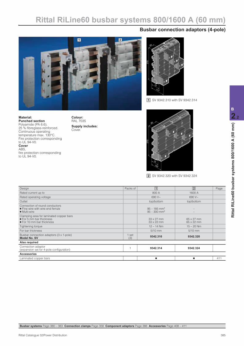
Busbar connection adaptors (4-pole)
Rittal RiLine60 busbar systems 800/1600 A (60 mm)
385Rittal Catalogue 32/Power Distribution
B
2.2
Rit
tal
RiL
ine
60
bu
sb
ar
sy
ste
ms
80
0/1
60
0 A
(6
0 m
m)
Material:Punched section Polyamide (PA 6.6), 25 % fibreglass-reinforced. Continuous operating temperature max. 130°C. Fire protection corresponding to UL 94-V0. Cover ABS, fire protection corresponding to UL 94-V0.
Colour:RAL 7035
Supply includes:Cover.
1 2
SV 9342.310 with SV 9342.3141
SV 9342.320 with SV 9342.3242
Design Packs of Page
Rated current up to 800 A 1600 A
Rated operating voltage 690 V~ 690 V~
Outlet top/bottom top/bottom
Connection of round conductors ● Fine wire with wire end ferrule ● Multi-wire
95 – 185 mm2 95 – 300 mm2
––
Clamping area for laminated copper bars ● For 5 mm bar thickness ● For 10 mm bar thickness
33 x 27 mm 33 x 22 mm
65 x 27 mm 65 x 22 mm
Tightening torque 12 – 14 Nm 15 – 20 Nm
For bar thickness 5/10 mm 5/10 mm
Busbar connection adaptors (3 x 1-pole)Model No. SV
1 set (3)
9342.310 9342.320
Also required
Connection adaptor (expansion set for 4-pole configuration)
1 9342.314 9342.324
Accessories
Laminated copper bars n n 411
1 2
Busbar systems Page 380 – 383 Connection clamps Page 358 Component adaptors Page 386 Accessories Page 408 – 411

Rittal RiLine60 busbar systems 800/1600 A (60 mm)Circuit-breaker component adaptors 160 A/250 A (4-pole)
386 Rittal Catalogue 32/Power Distribution
B
2.2
Rit
tal
RiL
ine
60
bu
sb
ar
sy
ste
ms
80
0/1
60
0 A
(6
0 m
m)
2 1
Material:Polyamide (PA 6.6), 25 % fibreglass-reinforced. Continuous operating temperature max. 130°C. Fire protection corresponding to UL 94-V0.
Colour:RAL 7035
Supply includes:Terminal cover and sliding blocks for switchgear attach-ment.
Note:Circuit-breaker component adaptors in 630 A version available on request.
Design Packs of
Construction width 120 mm 140 mm
Length 277 mm 310 mm
Rated current up to 160 A 250 A
Rated operating voltage 690 V~ 690 V~
Connection clamp Box terminal Box terminal
Connection of round conductors 35 – 120 mm2 35 – 120 mm2
Clamping area for laminated copper bars 18.5 x 15.5 mm 18.5 x 15.5 mm
Tightening torque ● Terminal screw ● Rail attachment
8 – 10 Nm4 – 6 Nm
8 – 10 Nm4 – 6 Nm
For switchgear make/model
ABB T1 (160 A), T2 (160 A) T3S (250 A), T4V (315 A)
Merlin Gerin NSC100 NS100, NS160, NS250L
Moeller Electric NZM1-4 (125 A) NZM2-4 (250 A)
Siemens – VL160X, VL160, VL250
For bar thickness 5/10 mm 5/10 mm
Cable outlet at the top1) Model No. SV
1 9342.504 9342.604
Cable outlet at the bottom1) Model No. SV
1 9342.514 9342.614
1) Switch outlet or outgoing cable.
1 2
SV 9342.504 1 SV 9342.6042
SV 9342.614 2 SV 9342.514 1
Busbar systems Page 380 – 383 Busbar connection adaptors Page 384/385 Connection clamps Page 358 Accessories Page 408 – 411