RF Handbook.pdf RF Handbook / Practical Guide to RF Level Control

OPERATION, INSTALLATION & MAINTENANCE MANUAL
RF LEVEL SWITCH Series RFLS10
LEVSEN CONTROLS & INSTRUMENTS B-4, Aditya Complex, Block C-3, Yamuna Vihar,
DELHI – 110 053
2
CONTENTS
INTRODUCTION OPERATING PRINCIPLE
FEATURES
APPLICATION CONSIDERATIONS SELECTION MECHANICAL INSTALLATION
ELECTRICAL INSTALLATION
SPECIFICATIONS
OPERATION
CALIBRATION TYPICAL APPLICATION FACTORY ASSISTANCE
INTRODUCTION
RF Level Switch operates in the low MHz radio frequency range. Radio frequency (RF) principle is utlised to
monitor the level of material available in a vessel at a particular level. Relay contacts are used to provide visual indication and also for interlocking purposes. RF level switch provides reliable Relay outputs and its functioning is independent of moisture, material temperature, Coating be conductive, non conductive, solids, liquids, corrosive or even tend to coat on the sensing probe.
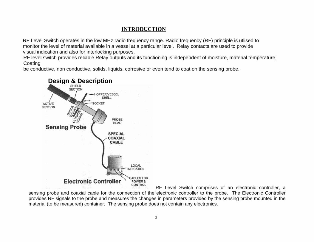
Design & Description
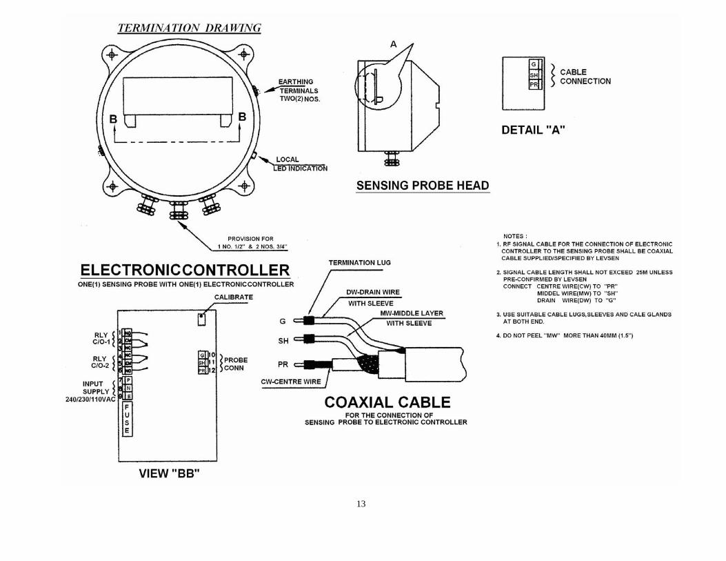
RF Level Switch comprises of an electronic controller, a sensing probe and coaxial cable for the connection of the electronic controller to the probe. The Electronic Controller provides RF signals to the probe and measures the changes in parameters provided by the sensing probe mounted in the material (to be measured) container. The sensing probe does not contain any electronics.
3
4
RF signal provided to the probe varies with the change of media (the application material having interparticle cohesive contact) upto the vessel body as reference ground. The material in transit or the suspended particles which do not have cohesive interparticle contact up to the vessel shell are not taken into account. The variation in RF signal is utilized to activate a relay and the relay contacts are available as output for further use. To protect the equipment from electrostatic charge developed in the vessel, an Electrostatic Charge Protector is provided in the Probe Head.
The most common probe design is a stainless steel rod insulated from the housing and bin wall by a low-dielectric insulator, such as PTFE/Teflon. These polymers have maximum operating temperatures of upto 250°C. Ceramics can be used for higher temperature applications or if abrasion resistance is required. For applications where the process material is conductive and corrosive, the probe is fully insulated with Teflon. The point level sensors are provided with build-up immunity or coating rejection functionality by the use of a shield section which is kept at the same potential and frequency as the measuring probe. Because current cannot flow between equal potentials, the measuring probe does not sense material build-up between the sensing probe and vessel wall.
The electronic circuitry of the probe performs the functions of:
1) Rectifying and filtering the incoming power, 2) Generating the radio frequency signal, 3) Measuring the changes in current flow, and 4) Driving and controlling interface devices such as relays and Interlocks.
OPERATING PRINCIPLE
LEVSEN RF level switch Series RFLS 10 works on Radio Frequency Principle. Independent but identical low power RF signals equal in frequency, phase, and amplitude and wave shape generated in Electronic Controller are provided to active and shield sections of the Sensing Probe whereas , the reference ground of electronics is connected to the vessel shell . The signal provided to the shield section is maintained constant by use of a compensating circuit in the Electronic Controller while the signal applied to the active section varies with the change of media between probe and the vessel shell. The suspended dust or material in transit do not have cohesive inter-particle contact and have no role in this RF principle of Level Sensing. The variation in active signal is compared with the constant shield signal. At a predetermined value of difference a relay is actuated to obtain potential free relay change over.
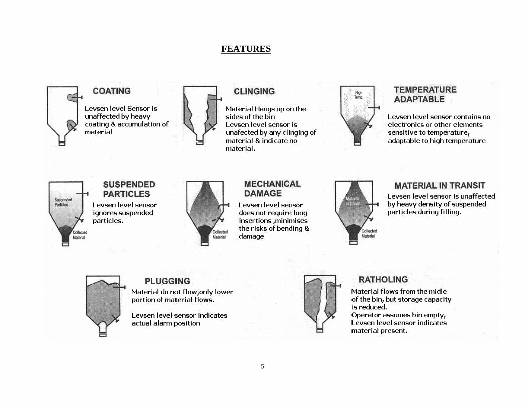
FEATURES
5
6
APPLICATION CONSIDERATIONS
Materials that are conductive (water-based liquids with a conductivity of 100 micromhos/cm or more) can cause a short circuit between a bare stainless steel probe and the vessel wall. As the liquid level drops, the probe remains wetted, providing a conductive path between the probe and the vessel wall. The faster the level changes, the more likely this false indication is to occur. It is advisable to use Teflon insulation on the conductive probe surface when the process fluid is conductive.
Temperature affects both the sensor components inside the vessel (active & shield sections and insulation) and the electronic components and housing outside. An active probe is typically made from stainless steel and, as such (unless it is coated), it is suitable for most applications. Probe insulators can be Teflon or ceramic, and should be selected for the operating temperature of the application. The housing and the electronics are affected by both the internal and external vessel temperatures.
Ambient temperature limits usually are specified by the manufacturer, but heat conduction from a high-temperature process is more difficult to evaluate. Heat conduction can be reduced by using an extended mounting coupling or one made of a low thermal conductivity material. If such methods are insufficient, the electronics may be mounted up to 20 ft away and connected via PTFE insulated coaxial cable. Housings must also be compatible with the equirements for hazardous, wash-down, wet, and/or dusty environments. Explosion-proof environments may require the housing to be certified. In addition, the active probe might need to be intrinsically safe.
If the process material is corrosive to stainless steel, the probe should be fully coated with Teflon for protection.
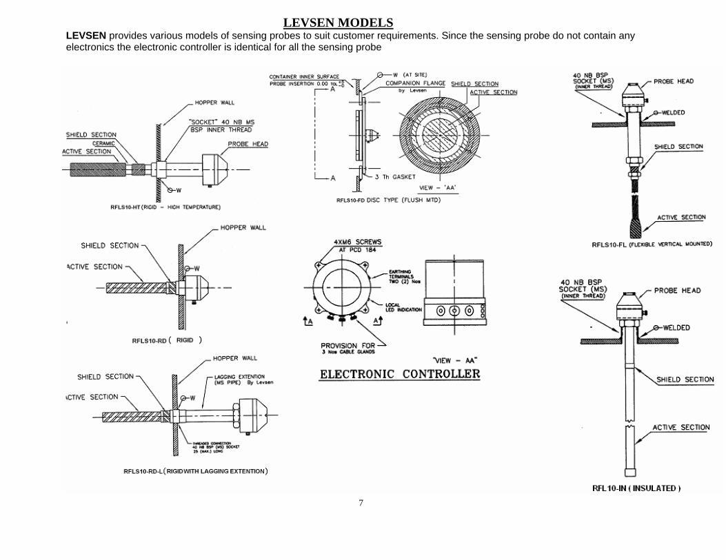
LEVSEN MODELS
LEVSEN provides various models of sensing probes to suit customer requirements. Since the sensing probe do not contain any electronics the electronic controller is identical for all the sensing probe
7
MECHANICAL INSTALLATION
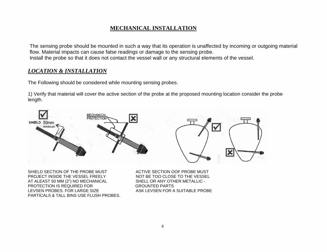
The sensing probe should be mounted in such a way that its operation is unaffected by incoming or outgoing material flow. Material impacts can cause false readings or damage to the sensing probe. Install the probe so that it does not contact the vessel wall or any structural elements of the vessel.
LOCATION & INSTALLATION The Following should be considered while mounting sensing probes. 1) Verify that material will cover the active section of the probe at the proposed mounting location consider the probe length.
SHIELD SECTION OF THE PROBE MUST ACTIVE SECTION OOF PROBE MUST PROJECT INSIDE THE VESSEL FREELY NOT BE TOO CLOSE TO THE VESSEL AT ALEAST 50 MM (2”) NO MECHANICAL SHELL OR ANY OTHER METALLIC - PROTECTION IS REQUIRED FOR GROUNTED PARTS LEVSEN PROBES. FOR LARGE SIZE ASK LEVSEN FOR A SUITABLE PROBE PARTICALS & TALL BINS USE FLUSH PROBES.
8
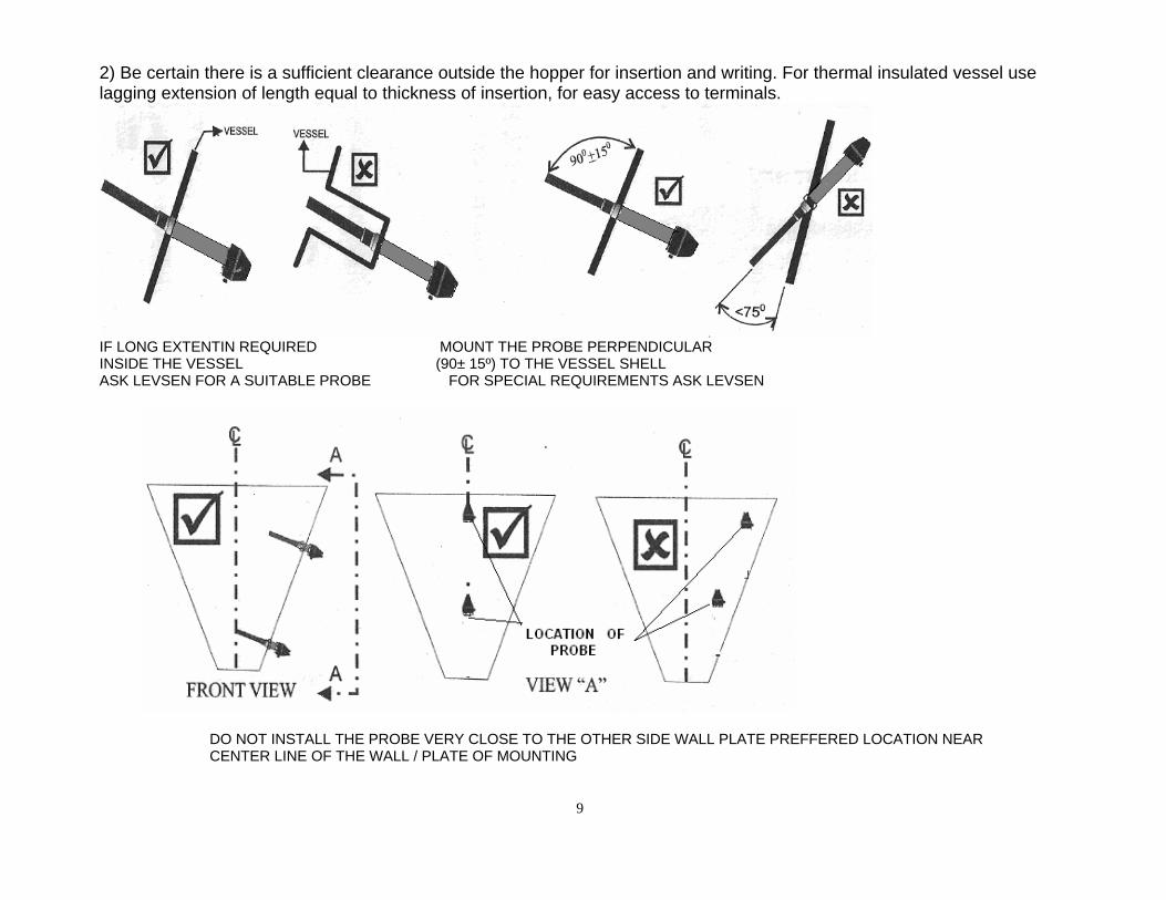
2) Be certain there is a sufficient clearance outside the hopper for insertion and writing. For thermal insulated vessel use lagging extension of length equal to thickness of insertion, for easy access to terminals.
IF LONG EXTENTIN REQUIRED MOUNT THE PROBE PERPENDICULAR INSIDE THE VESSEL (90± 15º) TO THE VESSEL SHELL ASK LEVSEN FOR A SUITABLE PROBE FOR SPECIAL REQUIREMENTS ASK LEVSEN
DO NOT INSTALL THE PROBE VERY CLOSE TO THE OTHER SIDE WALL PLATE PREFFERED LOCATION NEAR CENTER LINE OF THE WALL / PLATE OF MOUNTING
9
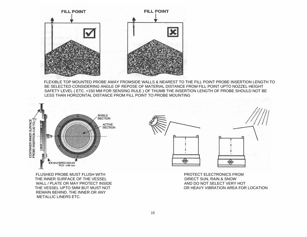
FLEXIBLE TOP MOUNTED PROBE AWAY FROMSIDE WALLS & NEAREST TO THE FILL POINT PROBE INSERTION LENGTH TO BE SELECTED CONSIDERING ANGLE OF REPOSE OF MATERIAL DISTANCE FROM FILL POINT UPTO NOZZEL HEIGHT SAFETY LEVEL ( ETC. +150 MM FOR SENSING RULE ) OF THUMB THE INSERTION LENGTH OF PROBE SHOULD NOT BE LESS THAN HORIZONTAL DISTANCE FROM FILL POINT TO PROBE MOUNTING
FLUSHED PROBE MUST FLUSH WITH PROTECT ELECTRONICS FROM
THE INNER SURFACE OF THE VESSEL DIRECT SUN, RAIN & SNOW WALL / PLATE OR MAY PROTECT INSIDE AND DO NOT SELECT VERY HOT THE VESSEL UPTO 5MM BUT MUST NOT OR HEAVY VIBRATION AREA FOR LOCATION REMAIN BEHIND. THE INNER OR ANY
METALLIC LINERS ETC.
10
ELECTRICAL INSTALLATION
ELECTRONIC CONTROLLER LOCATION & INSTALLATION
The following should be considered while mounting the electronic controller:
• Location Mount on convenient structure (near probe location) free from obstruction • Temperature Be sure ambient temperature is not more than specified temperature • Environment Install unit at a location so that there is no exposure to direct sunlight, rain or snow • Vibration If there is excess vibration in the area, use alternate mounting area or provide vibration absorbing material under the enclosure base. • Distance Make sure that cable distance from the Sensing probe to electronic controller is minimum possible .
11
12
PROBE LOCATION & INSTALLATION
The following should be taken care of while mounting sensing probes: i. Verify that material will cover the active section of the probe at the proposed mounting location. ii. Be certain that shield section of the probe must project freely inside the vessel (at least 2 inch or 50mm)
for Rod type/Flexible probes. iii. Be certain there is a sufficient clearance outside the hopper for inserting and wiring. For thermal insulated
vessel use lagging extension (of length equal to thickness of insulation) for easy access to terminals. iv. Disc type probe must be either flushed with inner surface of hopper wall or may project inside (up to 5mm)
but not remain behind the inner surface of the vessel. v. Probe must be almost perpendicular (90 + 15°) to the vessel wall on which it is to be mounted. vi. Active section must not be too close to any other grounded metal part of the hopper/Vessel maximum
possible gap must be maintained. Prefer location along the centre line of the wall/plate of the vessel. vii. Termination must be done with proper lugs & gland and each conductor must be totally isolated from each
other. viii. Probe length is selected considering angle of repose (for solids), roof thickness, mounting nozzle height
etc., as rule of thumb for solid materials, Horizontal distance from fill point/points must be less than the insertion length of the probe.
ix. Select location for flexible top mounted sensing probe nearest (possible) to the vertical centre axis of the filling point /points & maximum possible distance from side walls.
x. Probe grounding of hopper/vessel body with electronic controller must be ensured. xi. Do not provide additional metallic protection like pipe/channel/plate inside the vessel covering the sensing
probe, if provided must be removed, as this can result malfunctioning. For large size particles use disc type flush mounted Probes.
CABLE CONNECTION
POWER CONNECTIONS:-
Power connections (as specified) are made directly to the terminal blocks located in the electronic controller. Due to the low power consumption of the unit, (3VA) light gauge wiring of size 1.0mm sq. may be sufficient.
OUTPUT CONNECTIONS:- Out put relay connections are made directly to the terminal blocks located inside the electronic controller. These relay contacts (two numbers change over potential free contacts) are rated for 5amp at 220VAC non-in active or as specified. Output wiring should be compatible with the intend output load (less than relay contact rating
13
14
SPECIFICATIONS
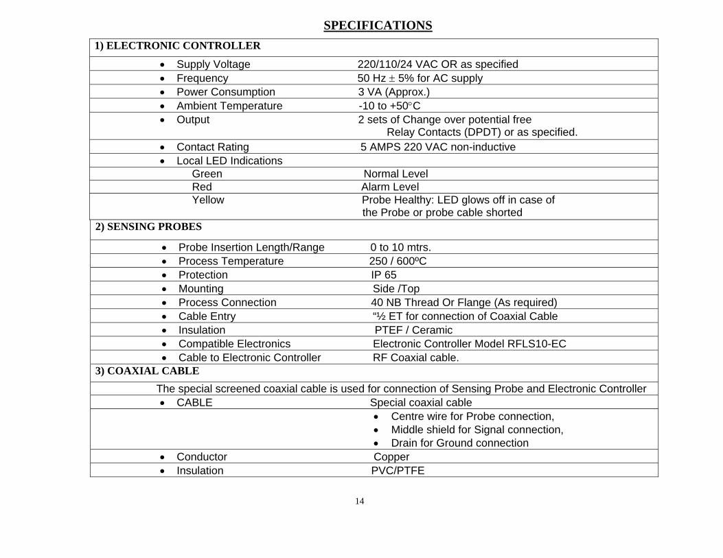
1) ELECTRONIC CONTROLLER
• Supply Voltage 220/110/24 VAC OR as specified • Frequency 50 Hz ± 5% for AC supply • Power Consumption 3 VA (Approx.) • Ambient Temperature -10 to +50°C • Output 2 sets of Change over potential free
Relay Contacts (DPDT) or as specified. • Contact Rating 5 AMPS 220 VAC non-inductive • Local LED Indications
Green Normal Level Red Alarm Level Yellow Probe Healthy: LED glows off in case of the Probe or probe cable shorted 2) SENSING PROBES
• Probe Insertion Length/Range 0 to 10 mtrs. • Process Temperature 250 / 600ºC • Protection IP 65 • Mounting Side /Top • Process Connection 40 NB Thread Or Flange (As required) • Cable Entry “½ ET for connection of Coaxial Cable • Insulation PTEF / Ceramic • Compatible Electronics Electronic Controller Model RFLS10-EC • Cable to Electronic Controller RF Coaxial cable.
3) COAXIAL CABLE
The special screened coaxial cable is used for connection of Sensing Probe and Electronic Controller • CABLE Special coaxial cable
• Centre wire for Probe connection, • Middle shield for Signal connection, • Drain for Ground connection
• Conductor Copper • Insulation PVC/PTFE
15
OPERATION START UP
ELECTRONIC UNIT:-
1. Verify that the ambient condition suitable (-10 to + 50° C. Max.). 2. Verify that the Electronic Controller is installed at convenient man height. 3. Verify that the Electronic Controller is not exposed to direct sunlight, rain or snow. 4. Verify that the mounting fasteners are tightened properly. 5. Verify that the Earthing grid is connected at both the earthing terminals of electronic unit 6. Verify that the Supply voltage is as specified on the terminals. 7.
PROBE:- 1. Verify that the Probe is mounted 90 (±) 15° to vessel wall/plate. 2. Verify that there is no Pipe cover Hood Canopy inside vessel over/near probe. 3. Verify that there is maximum gap from other walls/ any other metal parts. 4. Verify that the Shield section projection inside the vessel more than 50mm (2 ") 5. If flexible probe mounted from top only and distance from fill point is less than probe length. 6. If flushed probe: either flush with inner surface of the vessel or projects inside up to 5mm. 7. Verify probe ground terminal shows continuity with vessel/ earthing grid. 8. Switch on the appreciated supply voltage and yellow & either green or red Local LEDs glow.
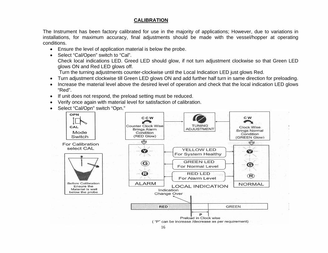
CALIBRATION
The Instrument has been factory calibrated for use in the majority of applications; However, due to variations in installations, for maximum accuracy, final adjustments should be made with the vessel/hopper at operating conditions.
• Ensure the level of application material is below the probe. • Select “Cal/Open” switch to “Cal”.
Check local indications LED. Greed LED should glow, if not turn adjustment clockwise so that Green LED glows ON and Red LED glows off. Turn the turning adjustments counter-clockwise until the Local Indication LED just glows Red.
• Turn adjustment clockwise till Green LED glows ON and add further half turn in same direction for preloading. • Increase the material level above the desired level of operation and check that the local indication LED glows
“Red”. • If unit does not respond, the preload setting must be reduced. • Verify once again with material level for satisfaction of calibration. • Select “Cal/Opn” switch “Opn.”
16
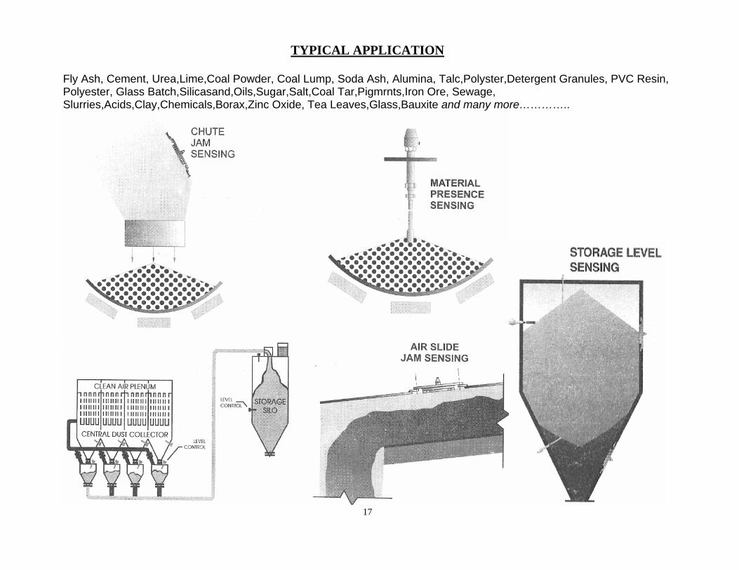
TYPICAL APPLICATION
Fly Ash, Cement, Urea,Lime,Coal Powder, Coal Lump, Soda Ash, Alumina, Talc,Polyster,Detergent Granules, PVC Resin, Polyester, Glass Batch,Silicasand,Oils,Sugar,Salt,Coal Tar,Pigmrnts,Iron Ore, Sewage, Slurries,Acids,Clay,Chemicals,Borax,Zinc Oxide, Tea Leaves,Glass,Bauxite and many more…………..
17
18
FACTORY ASSISTANCE
FOR ANY QUERIES, YOU MAY KINDLY CONTACT OUR TECHNICAL EXPERTS AT THE FOLLOWING ADDRESS:
LEVSEN CONTROLS & INSTRUMENTS
B-4, ADITYA COMPLEX, BLOCK C-3, YAMUNA VIHAR,
DELHI – 110 053
Ph.No. : 011-22914561 & 62 Fax No.: 011-22914562
E-mail : [email protected] [email protected] [email protected]
Website: www.levsencontrols.com