651 RF Admittance Single Point Level Switch GI830 · The 651 RF Admittance Single Point Level...
12
Form 830 (03.13) ©SOR Inc. 1/12 The 651 RF Admittance Single Point Level Switch is a level control which uses dielectric constant and conductivity to detect the level of liquids, slurries, granulars, and solids. When used with any of the RF Probes, it will provide accurate switching for level processes. The control features a fail-safe switch which reverses the operation of the relay. An LED inside the housing lights when the process is touching the probe. A sensitivity adjustment inside the control allows the user to increase or decrease sensitivity as needed. Optional time delay feature will delay switching on or off from 0 to 60 seconds. 651 RF Admittance Single Point Level Switch General Instructions Registered Quality System to ISO 9001 Design and specifications are subject to change without notice. For latest revision, go to www.sorinc.com NOTE: If you suspect that a product is defective, contact the factory or the SOR ® Representative in your area for a return authorization number (RMA). This product should only be installed by trained and competent personnel. Table of Contents Pre-Installation I/O Test and Calibration .... 1 Installation ....................................... 3 Electrical Connections ......................... 4 RF Probe Grounding Scheme ................. 5 Fail-Safe Mode .................................. 6 Circuit Board Replacement .................... 7 Sensor Replacement ........................... 7 Control Drawings ............................ 8-9 Troubleshooting ............................... 10 Dimensions ................................ 11-12 Pre-Installation I/O Test and Calibration Remove instrument from shipping box and visually inspect for obvious physical damage. Report any shipping damage to the carrier. Report any internal discrepancies to the factory representative in your area. Record the serial number from the nameplate should conversation with the factory be necessary. Remove housing cover. Place instrument on an insulated surface or support so sensor does not touch a conductive surface. Ensure area is safe and observe normal precautions for exposed and powered PC board. Apply proper line power per page 4, and observe LED. (See ) h g ). ous
Transcript of 651 RF Admittance Single Point Level Switch GI830 · The 651 RF Admittance Single Point Level...

Form 830 (03.13) ©SOR Inc. 1/12
The 651 RF Admittance Single Point Level Switch is a level control which uses dielectric constant and conductivity to detect the level of liquids, slurries, granulars, and solids. When used with any of the RF Probes, it will provide accurate switching for level processes.
The control features a fail-safe switch which reverses the operation of the relay. An LED inside the housing lights when the process is touching the probe. A sensitivity adjustment inside the control allows the user to increase or decrease sensitivity as needed. Optional time delay feature will delay switching on or off from 0 to 60 seconds.
651 RF Admittance Single Point Level Switch
General Instructions
Registered Quality System to ISO 9001
Design and specifications are subject to change
without notice.
For latest revision, go to www.sorinc.com
NOTE: If you suspect that a product is defective, contact the factory or the
SOR® Representative in your area for a return authorization number (RMA).
This product should only be installed by trained and competent personnel.
Table of Contents
Pre-Installation I/O Test and Calibration ....1
Installation .......................................3
Electrical Connections .........................4
RF Probe Grounding Scheme .................5
Fail-Safe Mode ..................................6
Circuit Board Replacement ....................7
Sensor Replacement ...........................7
Control Drawings ............................ 8-9
Troubleshooting ............................... 10
Dimensions ................................ 11-12
Pre-Installation I/O Test and Calibration
Remove instrument from shipping box and visually inspect for obvious physical damage. Report any shipping damage to the carrier. Report any internal discrepancies to the factory representative in your area. Record the serial number from the nameplate should conversation with the factory be necessary. Remove housing cover. Place instrument on an insulated surface or support so sensor does not touch a conductive surface. Ensure area is safe and observe normal precautions for exposed and powered PC board. Apply proper line power per page 4, and observe LED. (See
)
h
g
).
ous

2/12 Form 830 (03.13) ©SOR Inc.
Turn sensitivity adjustment clockwise (25 turns) to increase sensitivity until the LED illuminates indicating that the relay is energized. The unit is normally shipped in the
most sensitive position. The fail-safe mode selector switch JP1 is normally shipped in the lower position when
the instrument is oriented with the sensor pointing downward (6 o’clock). When the instrument is powered up, the relay is de-energized (LED goes out) when no process material is on the sensor.
Turn sensitivity adjustment counterclockwise to decrease sensitivity until the LED goes out. This normally occurs within 2-1/2 to 3-1/2 turns from the full increase position.
Turn the sensitivity adjustment slowly clockwise, then counterclockwise, 1/2 to 1 turn to check the null position for verification that the bridge is balanced. It is desirable to closely bracket the position where the LED went out.
Turn the sensitivity adjustment one turn counterclocwise from the null position. Next, slowly move a hand toward the probe to touch it. The LED should stay out until the probe is touched. Should it illuminate when in close proximity, turn sensitivity control counterclockwise so the LED stays out until a hand touches the probe.
Usually, 1-2 turns will locate the new null point. It is desirable to simulate the actual application conditions so the device can be more
precisely bench tested/calibrated, ensuring better on-line performance. When practical, use a small container of actual process material. If the actual process vessel is metal, use a metal container (coffee can, etc.) and ground it to the instrument housing. If the actual process vessel is an insulator, such as fiberglass, use a plastic container.
Immerse the sensor in the process material; the LED should illuminate. If not, it may be necessary to increase sensitivity.
To detect an interface, such as oil/water or foam/liquid, the lighter material must be on the sensor, then tuned out. Then adjust the sensitivity to detect the heavier process material. (See
and
)
SensitivityAdjustment
LED
Equipment Case Ground ConnectorBanana Plug to Sensor Jack
Top View
JP1 Fail Safe Selector Switch
Line Fuses
K1 Output Relay
Screw Clamp Terminal Block Timer Module (optional)
Form 830 (03.13) ©SOR Inc. 3/12
Installation
Oil
Water
Standard confi guration is a 3/4” NPT(M) pipe nipple that threads into a 3/4” NPT(F) ves-sel nozzle of half coupling. Allow a 4-inch turn radius for the housing. (See
and
))
Sometimes open tanks, vats, sumps or basins require a locally made bracket mount similar to shown in
pp.
Optional confi guration is a raised face ANSI flange. See catalog 1100 for selection. (See
ppp
and
)
Orientation. The control can be mounted in any position. Sensitivity is optimized when the greatest surface area of the sensor is parallel to the process level. (See
p
and
)When the process is adhesive, i.e. it tends to coat the sensor, it may be desirable to mount the unit on a 45o angle to reduce product build-up and to increase its effective surface area. (See
ggg
and
)
Placement and orientation of the sensor in a vessel is frequently determined by available nozzles. The sensor should be away from fill points to avoid false trips. The insulator bushing on the sensor should protrude a minimum of 1” from the inner wall of the vessel. The sensor must not touch any metal, nor should conductive product build-up be allowed to bridge between the sensor and a grounded metal tank wall.
If the sensor is a solid rod it may be cut or bent for clearance or placement. Use a 3-inch radius if a bend is required. It is permissible to increase sensor length by welding a length of identical rod to the supplied sensor. If the sensor is flexible cable, do not cut or modify it in any way, as sensor integrity will be compromised.
Time Delay: The Series 650 has a built-in 0.5 second delay to energize the output relay. An adjustable delay feature is optional. (See
yyy
, Timer Module.)
0.5 delay ON up to 60 seconds OFF 0.5 delay OFF up to 60 seconds ON
The optional time delay is a 12-turn pot; full CCW is 0.5 sec, full CW is 60 sec. When the timer board is unplugged, delay is 0.5 sec. This option may be used to increase the dead band at set point, compensate for wave effects or turbulence and free fall time in solids.
NOTE: Use delay ON with JP1 fail-safe in upper position.
Use delay OFF with JP1 fail-safe in lower position. (Opposite position of JP1 will reverse operation.)

4/12 Form 830 (03.13) ©SOR Inc.
Electrical Connections
Electrical power must be disconnected from explosion-proof models before
the cover is removed. Failure to do so could result in severe personal injury
or substantial property damage.
Terminal Block Label
Eight-Position Terminal Strip
NC1 C1 NO1 NO2 C2 NC2 L1 N
Output Connect external circuit wires as required to screw clamp terminals marked:
C1 (Common) C2 (Common) NO1 (Normally Open) NO2 (Normally Open) NC1 (Normally Closed) NC2 (Normally Closed)
Line Power Voltage Limits Max. Current Draw Board Marking 120 (95-130) VAC 20 mA Li, N (shown) 240 (195-250) VAC 10 mA Li, L2 24 ± 10% VDC 50mA + - 12 ± 10% VDC 100 mA + -
Ensure that wiring conforms to all applicable local and national electrical codes and install unit(s) according to relevant national and local safety codes.

Form 830 (03.13) ©SOR Inc. 5/12
120 VAC (651K7)Remove cover. Observe all applicable electrical codes and recognized wiring practices. Remove two #4 mounting screws and slide out PC board to expose green ground screw
(Internal Primary Equipment Ground/Earth) in base of housing. Connect ground wire to green ground screw on base of housing. (Ground wire should be a minimum of 18-AWG.)Reposition PC board, replace and tighten mounting screws. Ensure that banana plug on sensor lead wire is secure in sensor jack. Connect hot line power wire (typically black) to L1 position on screw clamp terminal block. Connect neutral line power wire (typically white) to N position on screw clamp terminal block. Replace cover. Apply power as desired.
240 VAC (651K8) Perform Steps 1 through 6 above. Connect second hot line power wire (typically red) to L2 position. Perform Steps 8 and 9 above.
SOR RF Probe Grounding Scheme
12 VDC (651K5)
24VDC (651K6) Perform Steps 1 through 5 above if a
case or equipment ground wire is pro-vided for connection to earth ground.
Connect positive line power wire to screw clamp terminal marked (+).
Connect negative line power wire to screw clamp terminal marked (-).
Replace cover. Apply power as desired.
SOR RF Probe Grounding Scheme
Critical Grounding Path =
CircuitBoard
Line
Neutral
Ground
Electronics Housing
Power Supply
Line
Neutral
Ground
ProcessConnection
SOR Supplied Stilling Well (optional)
Probe Center Conductive Element
IMPORTANT! Do notprovide separate earth grounding for the process connection. This can create a parallel grounding circuit that will impair operation and calibration.
Do not provide separate earth grounding
for the process connection. This can
create a parallel grounding circuit
that will impair operation and calibration.

6/12 Form 830 (03.13) ©SOR Inc.
Fail-Safe Mode
The fail-safe mode on either rising or falling level can be easily changed in the field. See procedure and chart below.
NOTE: Upon loss of power, or some component failures, the output relay is de-energized andits
contacts return to the “shelf position” NC (Normally Closed) to signal an alarm condition regard-
less of process level.
Disconnect line power supply.
Remove the housing cover. Determine whether switched external circuit must open or close (make or break) upon
loss of power to the instrument. Determine whether switched external circuit must open or close (make or break) at a
discrete level on rising or falling level when the instrument is powered. High-Level Fail Safe means the output relay will de-energize under high level conditions
and alarm a high-level condition upon loss of power. Conversely, Low-Level Fail Safe means the output relay will de-energize under low-level conditions and alarm a
low-level condition upon loss of power.The terminal block is labeled for a de-energized relay. Connect external circuit lead wires
to terminal block for desired logic. See chart below. Use needle-nose pliers to switch JP1 to Position A (lower) or Position B (upper) to
change fail-safe mode. Replace housing cover. Connect line power supply as shown on pages 4 and 5.
Electrical power must be disconnected from explosion-proof models before
the cover is removed. Failure to do so could result in severe personal injury
or substantial property damage.
Continuity Chart
Fail Safe
LO
Fail Safe
HI
NC1 C1 NO1 NO2 C2 NC2
NC1 C1 NO1 NO2 C2 NC2
NC1 C1 NO1 NO2 C2 NC2
NC1 C1 NO1 NO2 C2 NC2
Relay de-energized on high level
Relay de-energized on low level
Relay De-Energized
Relay De-Energized
Relay Energized
Switch Position Process Level Terminal Continuity
Relay Energized
Form 830 (03.13) ©SOR Inc. 7/12
Disconnect power to the unit. Remove the housing cover. Remove two mounting screws and slide out PC board to expose green ground screw
in the bottom of the housing. Remove the ground screw and ring terminal from inside the housing. Disconnect the banana plug from the sensor. Connect the banana plug from the new board to the sensor. Make sure the connection
is tight. Slide the ring terminal onto the ground screw. Replace the ground screw in the bottom
of the housing. Slide the PC board into the grooves in the plastic ring inside the housing. Replace the two mounting screws into the plastic ring. These screws are self-tapping.
Do not overtighten.
Circuit Board Replacement
Replacement Circuit Boards can only be ordered from SOR. Match the first five characters of your model number with those shown below to select the proper replacement board part number.
SOR Model Number Power Supply Circuit Board Part Number
651K5 12 VDC 99-401
651K6 24 VDC 99-376
651K7 12- VAC 99-377
651KB 240 VAC 99-378
Sensor Replacement
Disconnect power to the unit. Remove the housing cover. Remove two mounting screws and slide out the PC board to expose the sensor connection in the bottom of the housing. Disconnect the banana plug from the sensor. Unscrew the sensor from the housing. Apply thread sealant such as Teflon tape to the male threads of the new sensor. Thread the new sensor into the bottom of the housing. Connect the banana plug into the new sensor. Make sure the connection is tight. Slide the PC board into the grooves in the plastic ring inside the housing. Replace the two mounting screws into the plastic ring. These screws are self-tapping.
Do not overtighten. Replace the housing cover.
Replacement Sensors
See Form 1100 RF Catalog for replacement sensor model numbers.
NOTE: Replacement of circuit boards not
allowed on agency listed units.

8/12 Form 830 (03.13) ©SOR Inc.
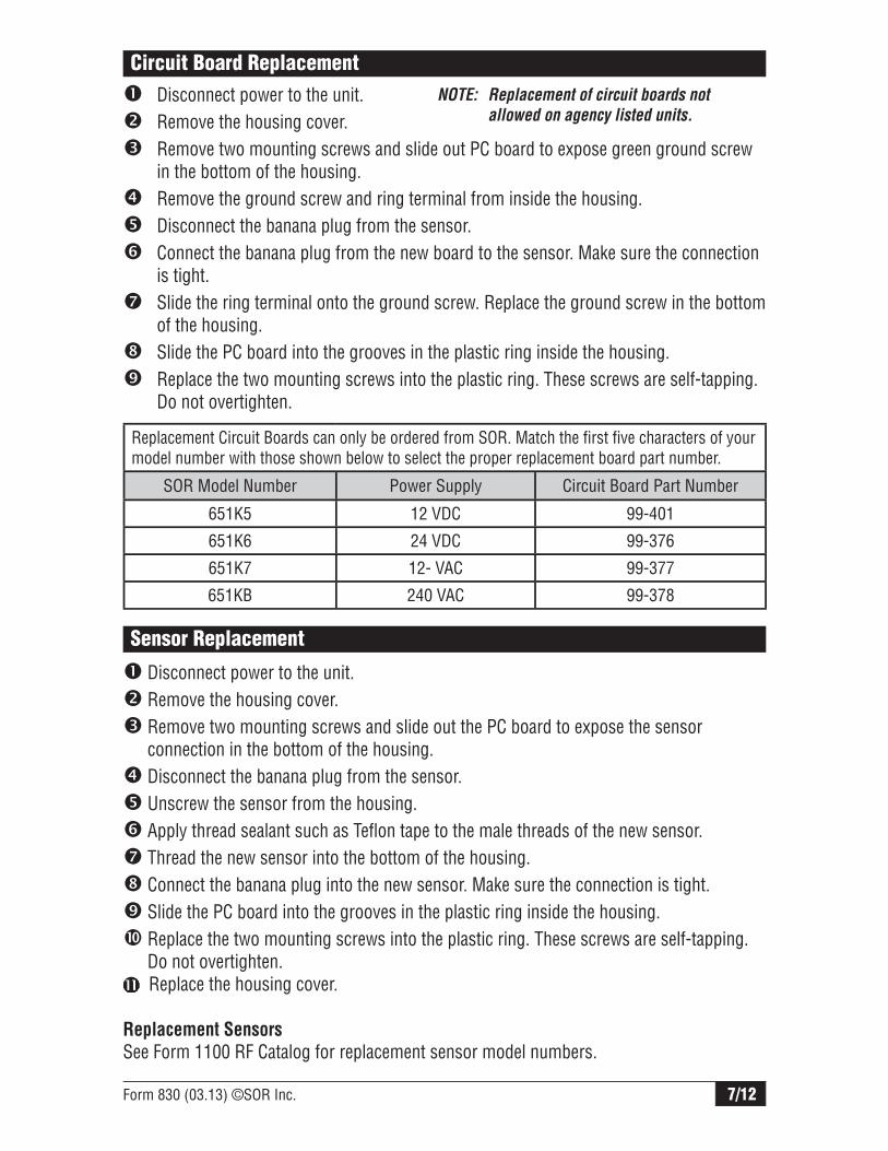
Control Drawing
Form 830 (03.13) ©SOR Inc. 9/12
Control Drawing

10/12 Form 830 (03.13) ©SOR Inc.
Troubleshooting
Symptom/Problem Possible Cause Corrective Action
LED will not illuminate, even at maxmum sensitivity setting (full clockwise 25 turns)
1. Antenna banana plug loose or disconnected. 2. No power to circuit.
3. Blown fuse.4. Faulty sensing circuit.
1. Plug antenna banana plug securely into sensor jack.2. Check voltage at terminal block as appropriate. L1 N 95-130 VAC L1 L2 195-250 VAC + - 24 + 10% VDC + - 12 + 1 0% VDC3. Replace line fuses F1 and F2.4. Replace PC board.
LED remains illuminated, even at minimum sensitivity setting (full counterclockwise 25 turns)
1. Antenna lead unplugged and touching housing or other ground.2. Antenna is shorted to case or ground.
1. Clean banana plug and insert into sensor jack.2. Ensure that bare end of antenna is not touching any metal part. Remove P1 if LED goes dark. Clean, repair or replace sensor assembly.
LED remains illuminated and goes out, but output relay is inoperative.
1. Bad driver transistor.
2. K1 relay contact damage.
3. Burned or broken lands terminal feed through K1.
1. Move JP1 to other position. If relay operates normally, replace PC board.2. Check condition of relay contacts and max load of external switched circuit.3. Replace K1 relay or PC board.
Device will not detect process material.
1. Sensitivity improperly set.2. Highly conductive product. 3. Heavy conductive product build-up on sensor.
1. Recalibrate according to Pre-Installation I/O Test and Calibration instructions on Page 1.2. Use sheathed sensor.3. Use sheathed sensor and periodically remove build-up.
Calibration drifts 1. Widely varying dielectric due to changing process material.2. Highly conductive product.3. Heavy conductive product build-up on sensor.
1. Recalibrate according to Pre-Installation I/O Test and Calibration instructions on Page 1.2. Use sheathed sensor.3. Use sheathed sensor and periodically remove build-up.
Corroded sensor Process material has chemically attacked sensor.
Use coated or sheathed sensor to provide corrision resistance.
Eroded or abraded sensor
Fast flowing or agitated process has physically attacked sensor.
Consider other sensor material or design, relocating sensor or a stilling well in liquid process.

Form 830 (03.13) ©SOR Inc. 11/12
Dimensions
A LENGTH (PER MODEL NUMBER)
116.74.59
96.03.78
B
C
19.10.75(INACTIVE SHEATH ONLY)
D
INACTIVE SHEATH LENGTH(PER MODEL NUMBER)
ELECTRICALCONNECTION3/4 NPTF
PROCESSCONNECTIONSEE TABLE
1
1
Dimensions are for reference only.Contact the factory for certified drawings
for a particular model number.
Linear = mm/inches
Drawing 0390652
PROCESS CONNECTIONDIM B DIM C
CABLE PROBE
ALL OTHER PROBES
CABLE PROBE
ALL OTHER PROBES
3/4 NPTM 87.83.46
94.13.71
205.28.08
211.68.33
1, 1-1/2, & 2 NPTM 99.73.92
97.33.83
217.28.55
214.88.46
FLANGED 158.56.24
158.56.24
276.010.87
276.010.87
STILLING WELL N/A 120.04.72 N/A 237.5
9.35
NOTES: 1. DIMENSION APPROXIMATE AND BASED ON A FIVE THREAD ENGAGEMENT.
1
SENSOR STYLE D
BARE 12.70.50
SHEATH 15.90.63
BARE WITHSTILLING WELL
26.71.05
SHEATH WITHSTILLING WELL
26.71.05
CABLE 7.900.31
INACTIVE SHEATH 15.90.63

12/12 Form 830 (03.13) ©SOR Inc.
14685 West 105th Street, Lenexa, KS 66215 913-888-2630 800-676-6794 USA Fax 913-888-0767
Registered Quality System to ISO 9001
Printed in USA www.sorinc.com
Dimensions
Dimensions are for reference only.
Contact the factory for certified drawings for a particular model
number.
Linear = mm/inches
Drawing 0390652
D
36.51.44
22.20.88
DETAIL ASCALE 1.5
3/4-16 UNF-2B X 11.10.44
MINIMUM CLEARANCE HOLEFOR INSTALLATION
54.92.16
50.82.00
31.81.25 28.4
1.12
31.81.25
54.02.13
27.01.06
DUAL RIGID PROBE DETAIL
SEE DETAIL A
DUAL CABLE PROBE DETAIL
3/4-16 UNF-2