RF Capacitance Level Switch igh sensitivit RF level switch ... · A02 RF Capacitance Level Switch...
32
A02 RF Capacitance Level Switch Operating instruction manual OI/A02-EN Rev. C High sensitivity RF level switch K-TEK Level Products Introduction This operating instruction manual provides the following information: – Specifications - see page 7 – Operation - see page 11 – Installation and calibration instructions - see page 12 – Maintenance and troubleshooting - see page 26
Transcript of RF Capacitance Level Switch igh sensitivit RF level switch ... · A02 RF Capacitance Level Switch...

A02RF Capacitance Level Switch
Operating instruction manual OI/A02-EN Rev. C
High sensitivity RF level switchK-TEK Level Products
IntroductionThis operating instruction manual provides the following information: – Specifications - see page 7 – Operation - see page 11 – Installation and calibration instructions - see page 12 – Maintenance and troubleshooting - see page 26

2 A02 RF Capacitance Level Transmitter and Switch | Operating instruction manual
TABLE OF CONTENTS
GENERAL DESCRIPTION 3
SPECIFICATIONS 7
OPERATION 11
INSTALLATION and CALIBRATION 12
THEORY of OPERATION 24
MAINTENANCE and TROUBLESHOOTING 26
WARRANTY INFORMATION 28

Operating instruction manual | A02 RF Capacitance Level Transmitter and Switch 3
1.1 KTEK’s Model A02 is used to detect the presence of a material at a given level in a tank, bin, or other container. In some cases, it can be used to detect an interface between materials. For these applications, it is recom-mended that one material be conductive and the other nonconductive. An example would be found in an oil and water separator. Applications requiring differential switching, such as sump pump control, can be accomplished with the adjustable differential option without additional latching relays.
1.2 TheModelA02isavailableinbothintegralandremotemountedconfigurations.Theintegralversionconsistsofahousingcontainingtheelectronicsfixeddirectlytothesensingprobe.Theremotemountedversioncon-sists of a pipestand or wall mount housing containing the electronics, an interconnecting cable, and a vessel mountedsensingprobewithterminatingcondulet(Seefigure1.1).
1.3 Sensing probes can be installed in two general positions: horizontal or vertical. A horizontal mount can only be used to produce single point alarm action, but has the advantage of a much greater capacitance change per inch of level change. Vertical mounting is required for differential switching applications. Sensing probes may bebareorinsulateddependingonthespecificapplication.Whenmountedverticallyandusedwithconductivematerials, the switching point is lowest point on a bare probe. With vertically mounted insulated probes, the switching point can be set anywhere within the probe length, regardless of the conductivity of the material.
1.4 Two or three element solid sensing probes are available. Three element probes use driven shield technology to eliminate the effects of sticky material buildup. Two element probes are more economical and are used where materialbuildupisnotexpected.Otheroptionsincludeextendedsolidprobesupto10feetinlength,flexiblecable probes, and special probes for high temperature or high pressure applications. Applications assistance is available through our factory and distributors.
1.5 Remote-mounted units require a coaxial interconnecting cable between the electronics and the sensing probe (Seefigure1.2).Therearethreetypesavailable:LowLoss,HighTemperature,andCombination,wherethefirst10feetofthecableissuitableforhightemperature.SeethespecificationsforthesecablesinSection2.0.Cablelengthshouldbespecifiedatpurchase.Bulklengthsof150feetandfieldterminationkitscanalsobepurchased.
1.6 Integral-mounted units are equipped with a short twisted pair for three element probes or a single wire for two elementprobes(Seefigure1.3).
1.0 GENERAL DESCRIPTION

4 A02 RF Capacitance Level Transmitter and Switch | Operating instruction manual
Explosion-Proof Remote-Mount
Integral-MountExplosion-Proof
Remote-MountNEMA 4
Figure 1.1
Operating instruction manual | A02 RF Capacitance Level Transmitter and Switch 5

6 A02 RF Capacitance Level Transmitter and Switch | Operating instruction manual

Operating instruction manual | A02 RF Capacitance Level Transmitter and Switch 7
2.0 SPECIFICATIONSENVIRONMENTAL
Electronics
Functional -40°F to 185°F / -40°C to 85°C
Rated Accuracy -40°F to 168°F / -40°C to 70°C
HazardousAreaClassification
Electronics
Integral-Mount= Class I, Div. 1 & 2, Groups B, C,& D; Class II, Div. 1 & 2 Groups E, F, & G; Class III; NEMA 4
Remote-Mount= NEMA4X(8”x6”box)
Probe Enclosure
E= Class I, Div. 1 & 2, Groups B, C,& D; Class II, Div. 1 & 2 Groups E, F, & G; Class III; NEMA 4
G= NEMA 4
Sensing Elements and Cable
Intrinsically Safe for Class I & II, Div. 1, Groups A -G
ELECTRICAL
Electronics
Input Power 90-130 VAC, 50-60 Hz, 7W
190-260 VAC, 50-60 Hz 7W
12-40 VDC
Output (1)DPDTRelay
Relay Contact Rating Resistive- 5 A 250 VAC; 5A 30 VDC
Inductive- 1/10 HP 125, 250 VAC
Sensitivity An increase of 0.2pF can be detected
Static Protection 100 amp Standard
RFI Protection Lessthan2Picofaradsshiftinoperationpointforunitinstandardhousingfroma5wattfieldat27,150 or 450 MHz, 5 feet from exposed sensing element, cable or power lines.
Coaxial Interconnecting Cable
Type Max. Length Temperature Range
Low Loss 50 ft -40°F to 160°F / -40°C to 70°C
High Temp 50 ft -40°F to 400°F / -40°C to 200°C
Combination 50 ft First 10 ft from probe same as High Temp.Remainder same as Combination
MECHANICAL
Process Connection 3/4” NPT Standard
(Flangedandothermountingsavailableuponrequest)
See probe compatibility list, on page 5, for temperature and pressure ratings.

8 A02 RF Capacitance Level Transmitter and Switch | Operating instruction manual
ORDERING INFORMATION:A02/a/b/c/d/e:/a Operating Voltage
/A 120 VAC /B 240 VAC /D 12 and 24 VDC/b Probe Type
Operating Temp. Operating Pressure/1 316SS Probe / 4” *Delrin® Lower Bushing A A/2 316SSProbe/4”*Teflon®LowerBushing C A/5 Fly Ash Probe / 8” 316SS Inactive Sheath D B/6 PVC Covered Cable / 13” 316SS Weight A D/8 PVC Covered Cable / 13” Nylon Weight A D/N *Teflon®CoveredCable/13”*Teflon® Weight C D/A 3Terminal316SSProbe-*Teflon®Insulator316SSShield C A
/B Macroprobe(3/4”ODProbe*Delrin®Bushing) A A/T Macroprobe(3/4”ODProbe*Teflon®Bushing) C A/K QuickReleaseClampProbe/4”*Teflon®Bushing A A/L QuickReleaseClampProbe/*Teflon® Sheathed Probe A A/R *Teflon®SheathedProbe/316SSMountingNipple C A/S *Teflon®SheathedProbe/*Teflon®MountingNipple C D/U Flush Mount Detector – Aluminum / *Delrin®` Bushing A D/W ConcentricShield304SS/TeflonSheathedProbe A A/X TeflonSheathedProbe/316SSInactiveSheath A A
/c Probe Length/xxx Rigid Probe in Inches; Cable Probe in Feet
/d Options/O No Options /C Epoxy Coating Aluminum Enclosure/F Flanged Connection/L Stainless Steel Tags/Z Any special option not included in above description. Includes but not limited to: Extended Lower
Bushing,10ampDPDTRelay(NotFMapproved)orRemote-MountConnectorCable/e Enclosure
/H Explosion Proof Note: Electronic enclosure is type H when remote mounted /G Remote NEMA 4 electronics are selected/E Remote Explosion Proof/Z Special, Explain
Operating Temperature CodesA -40 to 185ºF / -40 to 85ºCB -40 to 320ºF / -40 to 160ºCC -40 to 450ºF / -40 to 230ºCD 200 to 1400ºF / 95 to 760ºC
Operating Pressure CodesA 1500 psi @ 77ºF / 103 bar @ 25ºCB StaticHeadOnly(ConsultFactory)C 150 psi / 10.3 barD 100 psi / 7 bar
*Registered Trade Mark of E.I.DuPont Corp.

Operating instruction manual | A02 RF Capacitance Level Transmitter and Switch 9
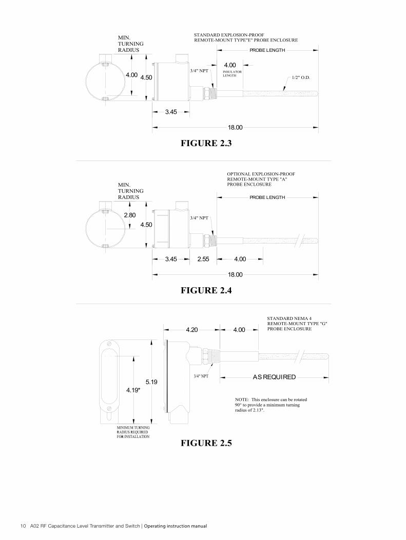
10 A02 RF Capacitance Level Transmitter and Switch | Operating instruction manual
MIN. TURNING RADIUS
4.504.00
3.45
3/4" NPT4.00
INSULATOR LENGTH
PROBE LENGTH
18.00
FIGURE 2.3
STANDARD EXPLOSION-PROOFREMOTE-MOUNT TYPE"E" PROBE ENCLOSURE
1/2" O.D.
OPTIONAL EXPLOSION-PROOFREMOTE-MOUNT TYPE "A" PROBE ENCLOSURE
FIGURE 2.4
18.00
PROBE LENGTH
3/4" NPT
3.45
4.50
MIN. TURNING RADIUS
FIGURE 2.5
2.80
2.55 4.00
4.19*5.19
4.20 4.00
AS REQUIRED
STANDARD NEMA 4REMOTE-MOUNT TYPE "G" PROBE ENCLOSURE
NOTE: This enclosure can be rotated90° to provide a minimum turningradius of 2.13".

Operating instruction manual | A02 RF Capacitance Level Transmitter and Switch 11
3.1 When material I n the vessel come into contact with the probe, the relay in the unit will change states. If the unit is programmed for operation in the “Fail-Safe High” mode, the relay will deenergize upon contact of the probe with the material. Since the two sets of relay contacts may be used in a number of different ways, the operator should know what to expect when a change in condition occurs and be prepared to take any action required by the system in which Model A02 is used.
3.2 The Model A02 includes driven shield technology to eliminate the effects of long interconnecting cable and al-lows the use of three element sensing probes to produce a high degree of coating rejection. The shield driver maintains identical voltage and phases between the center and shield elements of the sensing probe. Since no difference in potential exists between the center and shield elements, even with a conductive coating bridging theprobe,nocurrentcanflowfromthecenterelementpasttheshieldtoground(vesselwall).Therefore,onlythe actual material level in the vessel is detected.
3.3 TheModelA02isprovidedwithamodeselevctionjumperthatallowstheunittobeplacedinacalibrate(CAL)modeandthenreturnedtoitsnormaloperate(OPER)mode.ThisfeatureismostusefulwhentheA02isusedto sense very low dielectric materials. This feature allows the unit to be critically adjusted in the CAL mode. ReturningtheunittoitsOPERmodeintroducesacriticallydefinedoffsetthatstabilizestheunitwhileretainingmaximum sensitivity.
3.4 An adjustable time delay with a range of 0 to 30 seconds is standard on all units. It can be used to eliminate nuisance alarms caused by sloshing or wave action within a vessel. A jumper selection is provided to set the timedelaytooperateoneitherrising(TDR)orfalling(TDF)level.
For example, when the time delay is sey to actuate on rising level, the red LED will turn on instantaneously whentheliquidinthevesselfirsttouchestheprobe.TherelayanditsassociatedgreenLEDwillnotchangecondition until the material has been in continuous contact with the probe for the amount of time the delay is set for. When the material falls off of the probe, the relay, its green LED and the red LED will all change condition instantaneously.
When the time delay is set to actuate on falling level, the relay, its green LED and the red LED all operate in-stantaneouslywhenmaterialfirsttouchestheprobe.Whenmaterialfallsoffoftheprobe,theredLEDwillgooffinstantaneously but the relay and its green LED will not change condition until the time delay has elapsed.
3.5 Adjustableswitchingdifferential(ASD),anextracostoption,isalsousefulineliminatingnuisancealarms.Itismost commonly used to allow the Model A02 to be used as a two-point level controller. With ASD, the level must change by an amount determined during calibration before the unit will return to normal from the alarm state, The range of adjustment is 100% if probe length, independent of the zero range of the unit.
3.0 OPERATION

12 A02 RF Capacitance Level Transmitter and Switch | Operating instruction manual
4.0 INSTALLATION AND CALIBRATION4.1 After unpacking the unit, inspect it for any evidence of shipping damage. Any claims for damage due to shipping
mustbefiledwiththecarrierwhohandledthepackage(s).
4.2 Select a mounting location in accordance with good instrument practice. Reliability will be enhanced if the loca-tionisfreeofexcessivevibrationorenvironmentaltemperaturesoutsidethespecifiedrange.Besurethereissufficientclearancearoundthemountingpositiontoallowfortheturningradiusastheunitisscrewedintoplace.Additional clearances must be allowed to enable insertion of long rigid probes into the vessel opening and re-movalofthehousingcover.(Seefigure4.1forrecommendedmountingpractices.)
CAUTION: WHEN MAKING CONNECTIONS TO THE VESSEL, OBSERVE ALL SAFETY REQUIREMENTS OF THE AREA WHERE THE WORK IS BEING DONE. BE ESPECIALLY CAREFUL OF PRESSURE VES-SELS.
4.3 The Model A02 may not function properly if: • The capacitance change at the probe is less than 0.2 Picofarads. • The unit does not have an adequate ground reference. • Theprobe(barerodorcable)comesintocontactwithgroundreference. • The probe is located near a material inlet or outlet line. • The housing is not properly grounded.
IF ANY OF THE ABOVE APPLY TO YOUR APPLICATION, DO NOT INSTALL THE MODEL A02 AND CONTACT YOUR LOCAL DISTRIBUTOR, REPRESENTATIVE, OR THE ABB FACTORY FOR INSTRUCTIONS.
4.4 The Model A02 may be damaged if: • The temperature in the electronics housing exceeds -40°F to 168°F / -40°C to 70°C. • The sensing probe rated temperature or pressure is exceeded. • The electronics are subjected to excessive vibration ot shock. • Theprobeismounteddirectlyintheflowofmaterial • The supply power is not within the ratingd for the particular unit. • The relay contacts are subjected to a current in excess of their rating
IF ANY OF THE ABOVE APPLY OT YOUR APPLICATION, DO NOT INSTALL THE MODEL A02 UNTIL YOU CON-TACT YOUR LOCAL DISTRIBUTOR, REPRESENTATIVE, OR THE ABB FACTORY FOR INSTRUCTIONS.
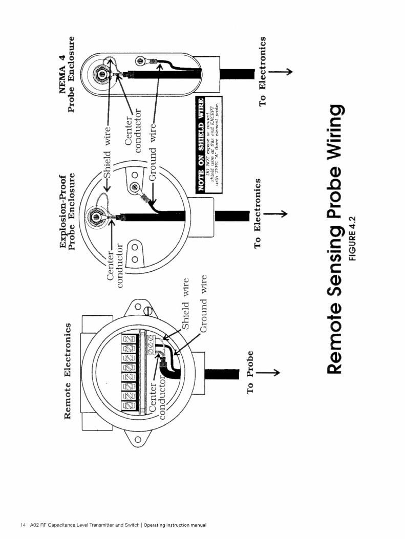
4.5 MountthesensingprobeusingasuitableNPTfittingorflange.(Seefigure4.2forremotesensingprobewiring.)Integralsensingprobesarefactorywired.(Seefigure1.2forremotecablepreparation.)
WARNING: Turn off and lock out all power before beginning installation.
DANGER: If installing the electronics in a hazardous area, install approved conduit seal within 18 inches / .5 m of the enclosure as required by National and Canadian Electrical Codes. Serious personal injury or prop-erty damage can result if seals are not installed.
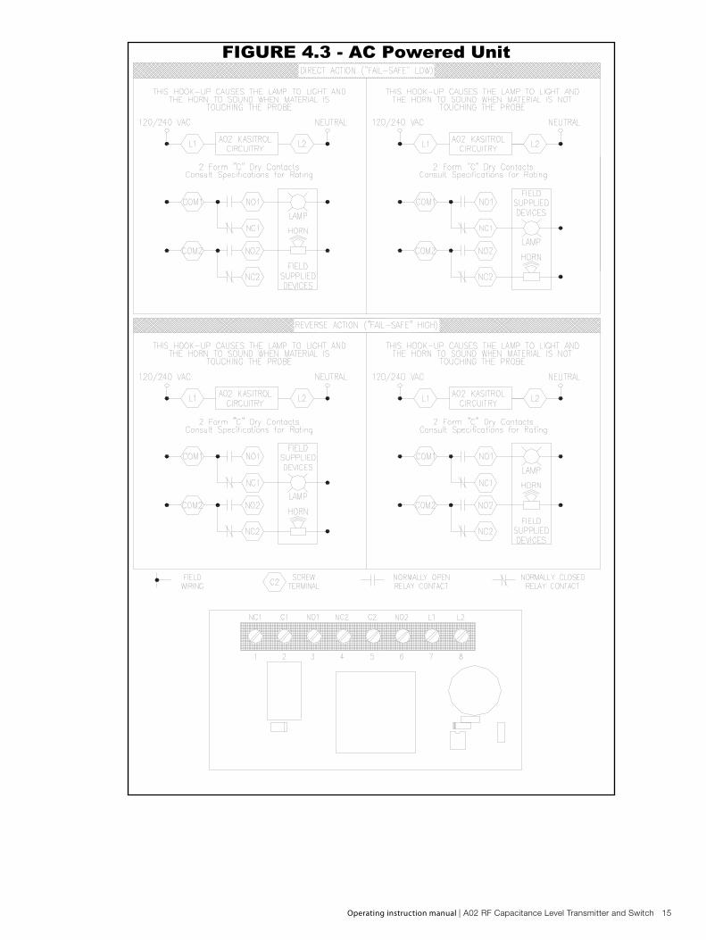
4.6 WiretheModelA02inaccordancewithoneofthetypicalwiringdiagramsoffigure4.3or4.4asmayberequiredby the particular application in which the unit is used. Because of the extremely wide range of control and/or alarm applications in which the unit may be used, it is not possible to show all conceivable wiring diagrams. Contact your distributor or ABB, if assistance is required.
CAUTION: BE SURE ALL WIRING COMFORMS TO THE REQUIREMENTS OF THE NATIONAL ELECTRICAL CODE AND ANY ENFORCING AUTHORITIES OR AGENCIES HAVING JURISDICTION OVER THE INSTALLATION. INSURE THAT ANY SPECIAL CONDITIONS, SUCH AS AREA HAVING EXPLOSION HAZARDS, ARE GIVEN FULL CONSIDERATION.

Operating instruction manual | A02 RF Capacitance Level Transmitter and Switch 13
These mounting locations are notrecommended. Consult factory
for additional information
SUGGESTED MOUNTING ARRANGEMENTS
24 Feet
Union Fitting Conduit
Maximum Lengthon Solid Rods.
Use Cable Probesfor lengths
exceeding 24 feet.
FittingSeal & Drain
this arrangements.if it is necessary to use
Conductive Bridge
Type "A", 3 Element Probe
FIGURE 4.1
Figure 4.1: Suggested Mounting Arrangements
14 A02 RF Capacitance Level Transmitter and Switch | Operating instruction manual
Operating instruction manual | A02 RF Capacitance Level Transmitter and Switch 15
FIGURE 4.3 - AC Powered Unit

16 A02 RF Capacitance Level Transmitter and Switch | Operating instruction manual
_
_ _
FIGURE 4.4 - DC Powered Unit
_
Operating instruction manual | A02 RF Capacitance Level Transmitter and Switch 17

18 A02 RF Capacitance Level Transmitter and Switch | Operating instruction manual
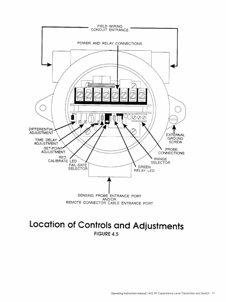
4.7 Calibratetheunitusingtheproceduresthatfollow.Seefigure4.5and4.6forlocationofadjustmentsandcon-trols.
1. The “Fail-Safe” selector is used to determine the mode of operation of the relay. If the selector is placed in the HI position, the relay will be energized until the material in the vessel touches the sensing probe, at which time the relay will de-energize. If the selector is placed in the LO position, the relay will be de-energized until the material in the vessel touches the sensing probe at which time the relay will energize. There are no devices which are absolutely “Fail-Safe”. “Fail-Safe” means that, in the event of the loss of power and some component failures, the instrument will indicate an alarm condition. If your application needs absolute Fail-Safe, a backup instrument or redundant system must be installed.
2. The RANGE jumper sets the maximum allowed capacitance for the unit. For most applications, RANGE 3 will be correct. For some applications, such as very long sensing probes, interface detection, or sensing elements mounted very close to the wall of the tank, selection of another range may be necessary. This is accomplished by moving the RANGE jumper on the printed circuit board. If after rotating the set-point potentiometer through its complete travel switch action, switch action cannot be achieved in the highest range, set the jumper to the next lower range and repeat the calibration steps. Continue to move to the lower ranges necessary to achieve switch operation.
3. The calibration potentiometer sets the Model A02 to a particular installation. Once set, no readjustment should be required unless the installation is changed or the unit is moves to a different location.
4. Two indicator lights are used to determine the proper setting of the calibration potentiometer and indicate thestateofthecontrolrelay.The“RLY”(relay)LEDisonwhentherelayisenergizedandoffwhentherelayisde-energized.Onceproperlycalibrated,thered“CAL”(calibrate)LEDisONwhenmaterialistouchingthe probe and OFF when material is not touching the probe.
5. The CAL/OPER jumper is used to aid the sometimes critical calibration of the unit for use with very low di-electric materials. Materials in this category are usually dry powders or light hydrocarbons. See the special calibration procedure for this purpose. For materials that do not fall into this category, place the CAL/OPER jumper in the OPER position and leave it there.
6. The TDR/TDF jumper is used to select the mode of operation for the time delay. To introduce a delay from the time material touches the probe until the relay changes state, place the jumper in the TDR (time delay rising)position.Tointroduceadelayfromthetimematerialfallsbelowtheprobeuntiltherelaychangesstae,placethejumperintheTDF(timedelayfalling)position.Ifthetimedelayfunctionisnotused,theposition of this jumper does not matter.
7. READ ALL STEPS BEFORE BEGINNING:
NOTE: STEPS 1 and 2 are to be performed regardless of the mounting plane of the sensing probe.
STEP1:RotatetheSETPOINT(S/P),TIMEDELAY(T/D)andDIFFERENTIAL(DIFF)adjust-mentsfullycounterclockwise(CCW)atleast20turnsoruntilaclickis heardforeverycomplete rotation.
STEP 2: Set the RANGE jumper in position 3.
HORIZONTALLY MOUNTED SENSING PROBE
STEP 3: See that material is not touching the sensing probe.
STEP4:RotatetheSETPOINTadjustmentslowlyclockwise(CW)untiltheread“CAL”LEDjustgoes off. If switch action has not occurred after 20 turns of the SETPOINT pot, move the RANGE jumper to the next lower setting and repeat steps 3 and 4.
4.0 INSTALLATIONANDCALIBRATION(Continued)

Operating instruction manual | A02 RF Capacitance Level Transmitter and Switch 19
STEP 5: Mentally note the position of the adjustment potentiometer.
STEP 6: Increase the material level until it is well above the sensing probe. Switch action will occur and the red “CAL” LED will turn on.
STEP 7: Counting the number of turns, turn the adjustment potentiometer slowly CW until the red “CAL” LED once again turns off, but no more than 15 turns.
STEP 8: Turn the adjustment back CCW 1/2 the number of turns that were counted in Step 7 above. The red “CAL” LED should be on.
STEP 9: Calibration is now complete.
VERTICALLY MOUNTED SENSING PROBE
NOTE: When detecting an interface, such as that between oil and water, the tank is considered to be “empty” for cali-brationpurposeswhentheheaviermaterial(water)isnottouchingthesensingprobe.DuringSTEPS1-4,thelightermaterial(oil)mustbecoveringthesensingprobesothatitmaybecalibratedout.
CALIBRATING for VERY LOW DIELECTRIC MATERIALS
Calibrating for materials with a very low dielectric constant can be somewhat more demanding than for materials that areeasiertodetect.UsingtheCAL/OPERjumpercanbeasignificantaidinsettingtheunittooperatereliablyinthistype of application. Use this method ONLY if you have trouble using either of the preceding methods.
STEP1: Rotate theSETPOINT (S/P),TIMEDELAY(T/D)andDifferential (DIFF)potentimetersfullycounter-clockwise(CCW)
STEP 2: Ste the RANGE jumper in position 3, the CAL/OPER jumper in the CAL position and the FS-HI/FS-LO jumper to the desired position. If the time delay function is to be used, place the TDR/TDF jumper in the desired position.
STEP 3: See that the material is not touching the sensing probe.
STEP4: RotatetheS/Ppotentionmeterclockwise(CW)untiltheredDETLEDjustgoesoff.Itisessential that this adjustment is as close as possible to the exact point where the red LED just goes out. In order to do this, it may be helpful to swing back and forth through this pointacoupleoftimes.BesurethatthefinaladjustmentismadeintheCWdirection.
STEP 5: Move the CAL/OPER jumper to the OPER position. The red LED should remain off.
STEP6: Toconfirmthatthecalibrationiscorrect,raisethemateriallevelinthevesseluntilitisincontact with the probe. The red LED should turn on. With a vertically mounted probe, it may be necessary to cover several inches of the probe in order to detect the material. Lower the material level in the vessel until material is no longer touching the probe. The red LED should go off.
STEP 7: Calibration is now complete.
4.0 INSTALLATIONANDCALIBRATION(Continued)
20 A02 RF Capacitance Level Transmitter and Switch | Operating instruction manual
CALIBRATING for VERY LOW DIELECTRIC MATERIALS
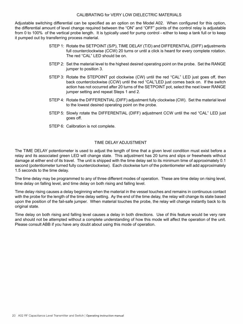
AdjustableswitchingdifferentialcanbespecifiedasanoptionontheModelA02.Whenconfiguredforthisoption,the differential amount of level change required between the “ON” and “OFF” points of the control relay is adjustable from 0 to 100% of the vertical probe length. It is typically used for pump control - either to keep a tank full or to keep it pumped out by transferring process material.
STEP1: RotatetheSETPOINT(S/P),TIMEDELAY(T/D)andDIFFERENTIAL(DIFF)adjustmentsfullcounterclockwise(CCW)20turnsoruntilaclickisheardforeverycompleterotation.The red “CAL” LED should be on.
STEP 2: Set the material level to the highest desired operating point on the probe. Set the RANGE jumper to position 3.
STEP3: Rotate theSTEPOINTpotclockwise (CW)until the red “CAL”LED justgoesoff, thenbackcounterclockwise(CCW)untilthered“CAL”LEDjustcomesbackon.Iftheswitchaction has not occurred after 20 turns of the SETPOINT pot, select the next lower RANGE jumper setting and repeat Steps 1 and 2.
STEP4: RotatetheDIFFERENTIAL(DIFF)adjustmentfullyclockwise(CW).Setthemateriallevelto the lowest desired operating point on the probe.
STEP5: SlowlyrotatetheDIFFERENTIAL(DIFF)adjustmentCCWuntilthered“CAL”LEDjustgoes off.
STEP 6: Calibration is not complete.
TIME DELAY ADJUSTMENT
The TIME DELAY potentiometer is used to adjust the length of time that a given level condition must exist before a relay and its associated green LED will change state. This adjustment has 20 turns and slips or freewheels without damage at either end of its travel. The unit is shipped with the time delay set to its minimum time of approximately 0.1 second(potentiometerturnedfullycounterclockwise).Eachclockwiseturnofthepotentiometerwilladdapproximately1.5 seconds to the time delay.
The time delay may be programmed to any of three different modes of operation. These are time delay on rising level, time delay on falling level, and time delay on both rising and falling level.
Time delay rising causes a delay beginning when the material in the vessel touches and remains in continuous contact with the probe for the length of the time delay setting. Ay the end of the time delay, the relay will change its state based upon the position of the fail-safe jumper. When material touches the probe, the relay will change instantly back to its original state.
Time delay on both rising and falling level causes a delay in both directions. Use of this feature would be very rare and should not be attempted without a complete understanding of how this mode will affect the operation of the unit. Please consult ABB if you have any doubt about using this mode of operation.

Operating instruction manual | A02 RF Capacitance Level Transmitter and Switch 21
1832
1 S
wam
p R
oad
Pra
iriev
ille,
Lou
isia
na 7
0769
US
ATel:(1)225-673-6100
Fax:(1)225-673-2525

22 A02 RF Capacitance Level Transmitter and Switch | Operating instruction manual
1832
1 S
wam
p R
oad
Pra
iriev
ille,
Lou
isia
na 7
0769
US
ATel:(1)225-673-6100
Fax:(1)225-673-2525

Operating instruction manual | A02 RF Capacitance Level Transmitter and Switch 23
1832
1 S
wam
p R
oad
Pra
iriev
ille,
Lou
isia
na 7
0769
US
ATel:(1)225-673-6100
Fax:(1)225-673-2525

24 A02 RF Capacitance Level Transmitter and Switch | Operating instruction manual
5.1 Gases have low dielectric constant values; most are essentially 1.0. At ambient temperature and pressure, their low dielectric value is negligible in liquid level measurement and can usually be ignored. Nonconductive materi-als have intermediate values; most of them between 1.5 and 10.0. Careful consideration of dielectric constant is a necessity . Changes in moisture content, bulk density, etc. must be considered. Conductive materials can be considered to have extremely high dielectric constants making them the easiest products to detect.
5.2 The Model A02 consists of an oscillator circuit, a detector circuit, a sensing probe, a setpoint adjustment, a com-parator circuit, a shield driver circuit, an indicator light, and a relay. See the block diagram, Figure 5.1. The unit also includes a power supply which is not shown on the block diagram.
5.3 The oscillator produces a 100 KHz signal that is coupled to the sensing probe through a resistance-capacitance network. The impedance of this network forms a voltage divider with the capacitive reactance of the sensing probe. A measure of the change in voltage across the divider is proportional to the change of capacitance at the probe.
5.4 The sensing probe forms one “plate” of a capacitor. The other “plate” is usually formed by the wall of the vessel in which the unit is mounted. Since neither the spacing between these two “plates” nor their area is allowed to vary, a difference in the dielectric constant of the material between the “plates” is the variable responsible for the capacitance change.
5.5 The detector output is a DC voltage that is inversely proportional to capacitance change. Low capacitance (low tanklevel)produceslargerDCvoltage,highcapacitance(hightanklevel)producessmallerDCvoltage.ThisvoltagecanbereadwithavoltmeteratpinTestPoint(TP)2onthecontrolboard.
5.6 The comparator monitors the voltages from the Setpoint Adjustment potentiometer and the Detector circuit. When coincidence is detected, the comparator output toggles. This action turns on the red “CAL” LED, and the relay driver energizes or de-energizes the relay and green “RLY” LED as required for the failsafe mode selected. Once calibrated, the red “CAL” LED shows the presence or absence of product at the setpoint level on the sens-ingprobe(LEDon=productpresent;LEDoff=productabsent).
5.7 The relay provides the means by which the Model A02 can control other devices such as lamps, small motors, motor starters, etc. It can be programmed either to energize when material contacts the sensing probe or to de-energize when material contacts the sensing probe. It should be noted that the green “RLY” LED indicates the stateoftherelay(LEDon=relayenergized;LEDoff=relayde-energized).
5.0 THEORY OF OPERATION
6.0 MAINTENANCE AND TROUBLESHOOTING
No routine maintenance is required other than keeping the interior of the unit clear of moisture and other contaminents. The A02 consists of three main sub-assemblies: the electronics boards, the sensing probe, and the sensor intercon-necting cable. The following troubleshooting guide will assist in identifying the problem source.
NOTE: The following procedures require power to be applied to the unit with the cover removed. Do not perform this procedure unless the area is know to be non-hazardous. Energizing circuits with the cover removed cancauseignitionofflammablegasesorvapors,resultinginseriouspersonalinjuryorpropertydamage.Extreme care should be used when working around exposed live circuits to avoid personal injury or death due to electrical shock. Always insure that the unit is properly grounded.

Operating instruction manual | A02 RF Capacitance Level Transmitter and Switch 25
100 KHzOSCILLATOR
PROTECTIONSTATIC
DRIVERSHIELD
SET-POINTCIRCUIT
CIRCUITDETECTOR
COMPARATOR
RELAY ANDGREEN "RLY" LED
RED "CAL" LED
FIGURE 5.1 - Block Diagram

26 A02 RF Capacitance Level Transmitter and Switch | Operating instruction manual
6.0 MAINTENANCE AND TROUBLESHOOTING6.1 FUNCTIONAL CHECK Disconnect the wiring between the sensing probe and the electronics boards. Do not disconnect the power sup-
ply wiring. If the RANGE shunt jumper is not in position 3, note its present position and move it to position 3. Turn the SETPOINT, TIME DELAY and DIFFERENTIAL adjustment potentiometers fully counterclockwise and note the state of the green “RLY” LED.
Find the switch point by rotating the SETPOINT potentiometer clockwise until the green “RLY” LED just changes
states. Rotate the SETPOINT adjustment back and forth, observing the amount of rotation necessary to achieve switch action. At switch point, less than 1/8 turn should be required. If the unit works correctly during the test above, but not in service, it is possible that the RANGE shunt jumper was incorrectly set for the application. Positions 1 and 2 are usually needed only with very long sensing elements, or where the switch point is several feet up from the end of the sensing probe.
6.2 RELAY CHECK Anohmmetercanbeusedtotestthecontinuityofthecontactsofthedouble-pole,double-throw(DPDT)control
relay.Operationalproblemsfrequentlyaretracedtoerrorsinwiringtotherelay.Commonly,thedifficultyarisesform misunderstanding of the Normally open/Normally closed terminology or a belief that power will be supplied from the relay contacts. Standard relay terminology refers to the “shelf”, that is, unpowered condition of the re-lay. When the relay is unpowered, continuity exists between the Normally closed and Common terminals. When the relay is energized, continuity exists between the Normally open and Common terminals and no continuity exists between the Normally closed and Common terminals.
NOTE: The relay is simply an electrically operated switch- opening or closing contacts. Power is not supplied b y therelay,butitcontrolspowerthatisprovidedbyfieldwiring.
6.3 SENSING PROBES Operational problems can often be traced to improper or incorrect installation of the sensing probe. The use of
large quantities of TEFLON® thread tape is not recommended. Care should be taken to insure integrity between the electronics and the vessel or other ground reference plane.
Thefollowingtestcanbeperformedusingananalog(non-digital)ohmmetertomeasuretheresistancebetween
the sensing probe element and ground. Disconnect all sensing probe wire at the three point terminal strip on the electronics module. See Figure 4.5 for location of the terminal strip.
6.3.1 INTEGRAL MOUNTED 2-ELEMENT PROBE Lower the level of material in the vessel until it is below the sensing probe. Measure the resistance between the
sensingprobewireandelectronicshousing.Measuredresistanceshouldbeinfinite.Resistancemeasurementsof less than 1 Megohm usually indicate presence of moisture or product in the probe insulation. Consult the fac-tory or your distributor.
6.3.2 INTEGRAL MOUNTED 3-ELEMENT PROBE, WITHOUT COATING Lower the level of material in the vessel until it is below the sensing probe. Measure the resistance between the
sensing probe wire and the electronics housing. Measure the resistance between the shield electrode and the sensing probe. Resistance measurements of less than 1 Megaohm usually indicate the presence of moisture or product in the probe insulation. Consult the factory or your distributor.
6.2.3 INTEGRAL MOUNTED 3-ELEMENT PROBE, WITH COATING Lower the level of material in the vessel until it is below the sensing probe. Measure the resistance between
the sensing probe wire and the electronics housing. Measure the resistance between the shield electrode wire and the electronics housing. Measure the resistance between the shield probe and the sensing probe. The measured value should not be less than those listed below.

Operating instruction manual | A02 RF Capacitance Level Transmitter and Switch 27
6.4 POSSIBLE PROBLEMS AND SOLUTIONS
PROBLEM POSSIBLE CAUSE SOLUTION
Instrument always indicates and alarm
No power to unit Check for correct supply voltage at terminals 7 & 8. See Section 2.0.
Excessive conductive build-up on sensingprobe(HLFS)
Longer shield length required.Consult distributor.
Sensing probe connecting cable defective.
Check for shorts between conductors of cable.
Improper calibration See Section 4.0
Bad electronic unit See Section 6.0
Instrument never indicates an alarm Excessive conductive build-up Longer shield length required.Consult distributor.
Sensing probe connecting cable defective
Check for open circuit in connecting cable.
Improper calibration See Section 4.0
Bad electronic unit See Section 6.0
Unit will not stay in calibration Sensing probe connecting cable defective
Check for open circuit in connecting cable
Poor integrity between electronics and vessel/reference ground.
Secure ground connection
Poor sensitivity Improper RANGE jumper setting See Section 4.5
6.5 TROUBLESHOOTING VOLTAGE CHECKSTP1 100 KHz Square Wave
TP2 DetectorOutput(Valuedependentuponprobecapacitance)
TP3 Setpoint Voltage
TP4 +12 VDC ±.5 VDC
TP5 Common(Ground)
28 A02 RF Capacitance Level Transmitter and Switch | Operating instruction manual
7.0 WARRANTY5 YEAR WARRANTY FOR:KM26 Magnetic Liquid Level Gauges; MagWave Dual Chamber System; LS Series Mechanical Level Switches (LS500,LS550,LS600,LS700,LS800&LS900);ECExternalChambersandST95SealPots.
3 YEAR WARRANTY FOR:KCAP300 & KCAP400 capacitance switches.
2 YEAR WARRANTY FOR:AT100, AT100S and AT200 series transmitters; VF20 and VF30 vibrating fork switches; RLT100 and RLT200 reed switch level transmitters; TX, TS, TQ, IX and IM thermal dispersion switches; IR10 and PP10 External Relays; MT2000 radar level transmitters; RI100 Repeat Indicator; KP paddle switches; A02, A75 & A77 RF capacitance level switches and A38 RF capacitance level transmitters; Buoyancy Level Switches (MS50, MS10, MS8D & MS8F);MagneticLevelSwitches(MS30,MS40,MS41,PS35&PS45).
1 YEAR WARRANTY FOR:KM50 gauging device; AT500 and AT600 series transmitters; LaserMeter and SureShot series laser transmitters; LPM200 digital indicator; DPM100 digital indicators; APM100 analog indicators; KVIEW series digital indicators and controllers; SF50 and SF60 vibrating fork switches, KB Electro-Mechanical Continuous Measuring Devices, KSONIK ultrasonic level switches, transmitters & transducers.
SPECIAL WARRANTY CONSIDERATIONS:ABBdoesnothonorOEMwarrantiesforitemsnotmanufacturedbyABB(i.e.PalmPilots).Theseclaimsshouldbe handled directly with the OEM.
ABB will repair or replace, at ABB’s election, defective items which are returned to ABB by the original purchaser withintheperiodspecifiedabovefromtheshipment date of the item and which is found, upon examination by ABB, to its satisfaction, to contain defects in materials or workmanship which arose only under normal use and service and which were not the result of either alterations, misuse, abuse, improper or inadequate adjustments, applications or servicing of the product. ABB’s warranty does not include onsite repair or services. Field service rates can be supplied on request.
If a product is believed to be defective, the original purchaser shall notify ABB and request a Returned Material Authorization before returning the material to ABB, with transportation prepaid by the purchaser. (Request door todoordeliveryviaNewOrleansInternationalAirportlocatedinLouisiana,USA.)Theproduct,withrepairedorreplaced parts, shall be returned to the purchaser at any point in the world with transportation prepaid by ABB for best-way transportation only. ABB is not responsible for expedited shipping charges. If the product is shipped to ABB freight collect, then it will be returned to the customer freight collect.
If inspection by ABB does not disclose any defects in material or workmanship, ABB’s normal charges for repair andshipmentshallapply(minimum250.00USD).
ThematerialsofconstructionforallABBproductsareclearlyspecifiedanditistheresponsibilityofthepurchaserto determine the compatibility of the materials for the application.
THE FOREGOING WARRANTY IS ABB’S SOLE WARRANTY AND ALL OTHER WARRANTIES EXPRESSED, IMPLIED, OR STATUTORY, INCLUDING ANY IMPLIED WARRANTY OF MERCHANTABILITY OF FITNESS FOR A PARTICULAR PURPOSE, ARE EXCLUDED AND NEGATED TO THE MAXIMUM EXTENT PERMITTED BY LAW. NO PERSON OR REPRESENTATIVE IS AUTHORIZED TO EXTEND ANY OTHER WARRANTY OR CRE-ATE FOR ABB ANY OTHER LIABILITY IN CONNECTION WITH THE SALE OF ABB’S PRODUCTS. THE REM-EDIES SET FORTH IN THIS WARRANTY ARE EXCLUSIVE OF ALL OTHER REMEDIES AGAINST ABB. ABB SHALL NOT BE LIABLE FOR ANY CONSEQUENTIAL, INCIDENTAL, OR SPECIAL DAMAGES OF ANY KIND. ABB’S SOLE OBLIGATION SHALL BE TO REPAIR OR REPLACE PARTS (FOUND TO BE DEFECTIVE IN MA-TERIALSORWORKMANSHIP)WHICHARERETURNEDBYTHEPURCHASERTOABB.

Operating instruction manual | A02 RF Capacitance Level Transmitter and Switch 29

30 A02 RF Capacitance Level Transmitter and Switch | Operating instruction manual

Operating instruction manual | A02 RF Capacitance Level Transmitter and Switch 31
OI/
A02
-EN
Rev
. C
06.2
012
Contact us
NoteWe reserve the right to make technical changes or modify the contents of this document without prior notice. With regard to purchase orders, the agreedparticulars shall prevail. ABB does not accept any responsibility whatsoever for potential errors or possible lack of information in this document.
We reserve all rights in this document and in the subject matter and illustrations contained therein. Any reproduction, disclosure to third parties or utilization of its contents - in whole or in parts – is forbidden without prior written consent of ABB.
Copyright© 2012 ABBAll rights reserved
ABB Inc. 18321 Swamp RoadPrairieville, LA 70769 USAPhone: +1 225 673 6100Service: +1 225 677 5836Fax: +1 225 673 2525Service e-mail: [email protected]
www.abb.com/level