Rexroth TRANS200 · PDF fileRexroth TRANS200 NC Programming ... 6 Auxiliary Functions (M) 6-1...
152
295379 Edition 02 Rexroth TRANS200 NC Programming Instructions Application Manual Industrial Hydraulics Electric Drives and Controls Linear Motion and Assembly Technologies Pneumatics Service Automation Mobile Hydraulics
-
Upload
hoangtuyen -
Category
Documents
-
view
213 -
download
1
Transcript of Rexroth TRANS200 · PDF fileRexroth TRANS200 NC Programming ... 6 Auxiliary Functions (M) 6-1...
295379Edition 02
Rexroth TRANS200NC Programming Instructions
Application Manual
IndustrialHydraulics
Electric Drivesand Controls
Linear Motion andAssembly Technologies Pneumatics
ServiceAutomation
MobileHydraulics
About this Documentation NC Programming Instructions
DOK-TRA200-NC**PRO*V22-AW02-EN-P
Rexroth TRANS200
NC Programming Instructions
Application Manual
DOK-TRA200-NC**PRO*V22-AW02-EN-P
Document Number 120-2250-B312-02/EN
This documentation describes the programming of the NC functions ofthe TRANS200 controller family.
Description ReleaseDate
Notes
120-2250-B312-01/EN 10.2002 Valid from version 22
120-2250-B312-02/EN 07.2003 Corrections included
� 2003 Bosch Rexroth AG
Copying this document, giving it to others and the use or communicationof the contents thereof without express authority, are forbidden. Offendersare liable for the payment of damages. All rights are reserved in the eventof the grant of a patent or the registration of a utility model or design(DIN 34-1).
The specified data is for product description purposes only and may notbe deemed to be guaranteed unless expressly confirmed in the contract.All rights are reserved with respect to the content of this documentationand the availability of the product.
Bosch Rexroth AGBgm.-Dr.-Nebel-Str. 2 • D-97816 Lohr a. Main
Telephone +49 (0)93 52/40-0 • Tx 68 94 21 • Fax +49 (0)93 52/40-48 85
http://www.boschrexroth.com/
Dept. BRC/ESM5 (GG)
Dept. BRC/ESM6 (DiHa)
This document has been printed on chlorine-free bleached paper.
Title
Type of Documentation
Document Typecode
Internal File Reference
Purpose of Documentation
Record of Revisions
Copyright
Validity
Published by
Note
NC Programming Instructions Contents I
DOK-TRA200-NC**PRO*V22-AW02-EN-P
Contents
1 General 1-1
1.1 General Information ...................................................................................................................... 1-1
1.2 Program and Data Organization ................................................................................................... 1-2
2 NC Program 2-1
2.1 Program Structure......................................................................................................................... 2-1
Advance Program .................................................................................................................... 2-1
Reverse Program..................................................................................................................... 2-1
2.2 Elements of a NC Block ................................................................................................................ 2-2
Block Numbers......................................................................................................................... 2-2
2.3 NC Word ....................................................................................................................................... 2-3
Branch Label ............................................................................................................................ 2-4
Note.......................................................................................................................................... 2-4
Comment ................................................................................................................................. 2-5
2.4 Available Addresses...................................................................................................................... 2-5
3 Motion Commands, Dimension Inputs 3-1
3.1 Coordinate System........................................................................................................................ 3-1
3.2 Motion Commands........................................................................................................................ 3-2
3.3 Measurements .............................................................................................................................. 3-3
Absolute Dimension Entry "G90" ............................................................................................. 3-3
Incremental Dimensions "G91" ................................................................................................ 3-4
3.4 Zero Points.................................................................................................................................... 3-5
3.5 Zero Offsets .................................................................................................................................. 3-6
Adjustable Zero Offsets "G54 - G59"....................................................................................... 3-8
Coordinate Rotation with Angle of Rotation "P"....................................................................... 3-9
Programmable Absolute Zero Offset "G50", Programmable Incremental Zero Offset"G51"...................................................................................................................................... 3-10
Programmable Zero Point of Workpiece "G52" ..................................................................... 3-11
Cancel Zero Offsets "G53"..................................................................................................... 3-12
Adjustable General Offset in the Zero Offset Table............................................................... 3-13
Read/Write Zero Offset Data from the NC Program via "OTD" ............................................. 3-13
3.6 Level Selection............................................................................................................................ 3-13
Axis Number, Axis Designation and Axis Meaning................................................................ 3-14
Plane Selection "G17", "G18", "G19"..................................................................................... 3-14
3.7 Go to Axes Reference Point "G74" ............................................................................................. 3-15
3.8 Driving against a Hard Stop ........................................................................................................ 3-16
Feed to Positive Stop "G75" .................................................................................................. 3-16
Cancel All Axis Preloads "G76" ............................................................................................. 3-18
II Contents NC Programming Instructions
DOK-TRA200-NC**PRO*V22-AW02-EN-P
3.9 Switching to a 2nd Encoder System (Adaptive Depth) .............................................................. 3-18
Application.............................................................................................................................. 3-18
New Axis Parameter .............................................................................................................. 3-19
G Codes to Switch to a 2nd Encoder System......................................................................... 3-19
4 Motion Blocks 4-1
4.1 Axes .............................................................................................................................................. 4-1
Linear Main Axes ..................................................................................................................... 4-1
Rotary Main Axes..................................................................................................................... 4-1
Linear and Rotary Auxiliary Axes............................................................................................. 4-2
4.2 Interpolation Conditions ................................................................................................................ 4-2
Following Error-Free Interpolation "G06"................................................................................. 4-2
Interpolation with Lag Distance "G07" ..................................................................................... 4-5
Optimal Speed Block Transition "G08" .................................................................................... 4-8
Speed-Limited Block Transition "G09"................................................................................... 4-10
Exact Stop "G61" ................................................................................................................... 4-12
Rapid NC Block Transition "G62" .......................................................................................... 4-14
4.3 Interpolation Functions................................................................................................................ 4-17
Linear Interpolation, Rapid Traverse "G00" ........................................................................... 4-17
Linear Interpolation, Feed "G01"............................................................................................ 4-18
Circular Interpolation "G02" / "G03" ....................................................................................... 4-19
Helical Interpolation ............................................................................................................... 4-25
Tapping "G63" / "G64" ........................................................................................................... 4-27
Tapping "G64" - Speed Reduction......................................................................................... 4-31
4.4 Feed ............................................................................................................................................ 4-31
F Word ................................................................................................................................... 4-31
Dwell Time "G04"................................................................................................................... 4-32
Basic Connections Between Programmed Path Velocity (F) and Axis VelocitiesFeed:Programmed path velocity (F) ...................................................................................... 4-33
Adaptive Feed Control "G25, G26" ........................................................................................ 4-35
4.5 Spindle Speed............................................................................................................................. 4-37
S Word for the Spindle Speed Specification.......................................................................... 4-37
Select Main Spindle "SPF"..................................................................................................... 4-39
Start-up Logic for Endlessly Rotating Rotary Axes................................................................ 4-39
5 Tool Compensation 5-1
5.1 Tool Path Compensation............................................................................................................... 5-1
Inactive Tool Path Compensation............................................................................................ 5-1
Active Tool Path Compensation............................................................................................... 5-2
Contour Transitions.................................................................................................................. 5-3
Establishment of Tool Path Compensation at Start of Contour ............................................... 5-7
Removal of Tool Path Compensation at End of Contour......................................................... 5-9
Change in direction of compensation .................................................................................... 5-11
5.2 Activating and Canceling Tool Path Compensation.................................................................... 5-11
Canceling Tool Path Compensation "G40"............................................................................ 5-11
Tool Path Compensation, Left "G41"..................................................................................... 5-12
Tool Path Compensation, Right "G42"................................................................................... 5-12
NC Programming Instructions Contents III
DOK-TRA200-NC**PRO*V22-AW02-EN-P
Inserting an Arc Transition Element "G43" ............................................................................ 5-15
Inserting a Chamfer Transition Element "G44"...................................................................... 5-15
5.3 Tool Length Compensation......................................................................................................... 5-16
No Tool Length Compensation "G47".................................................................................... 5-17
Tool Length Correction, Positive "G48" ................................................................................. 5-17
Tool Length Correction, Negative "G49"................................................................................ 5-18
5.4 D corrections ............................................................................................................................... 5-18
6 Auxiliary Functions (M) 6-1
6.1 General.......................................................................................................................................... 6-1
Spindle Control Commands..................................................................................................... 6-2
Spindle Positioning .................................................................................................................. 6-3
7 Events 7-1
7.1 Definition of NC Events ................................................................................................................. 7-1
7.2 Influencing Events......................................................................................................................... 7-1
Wait until Event is Set "WES" .................................................................................................. 7-1
Wait until Event is Reset "WER".............................................................................................. 7-1
7.3 Conditional Branches for Events................................................................................................... 7-2
Branch if Event is Set "BES".................................................................................................... 7-2
7.4 Asynchronous Handling of NC Events.......................................................................................... 7-2
Call Subroutine if Event is Set "BEV"....................................................................................... 7-3
Program Branching if Event is Set "JEV"................................................................................. 7-3
Cancel Event Monitoring "CEV"............................................................................................... 7-4
8 Process and Program Control Commands 8-1
8.1 Program Control Commands ........................................................................................................ 8-1
Program End with Reset "RET" ............................................................................................... 8-1
Branch with Stop "BST" ........................................................................................................... 8-1
Programmed Halt "HLT" .......................................................................................................... 8-1
Branch Absolute "BRA"............................................................................................................ 8-1
8.2 Subroutines ................................................................................................................................... 8-2
Subroutine Technique.............................................................................................................. 8-2
Subroutine Structure ................................................................................................................ 8-2
Subroutine Nesting .................................................................................................................. 8-2
Subroutine Call "BSR" ............................................................................................................. 8-3
Return from Subroutine "RTS"................................................................................................. 8-3
8.3 Reverse Vectors............................................................................................................................ 8-4
Set Reverse Vector "REV"....................................................................................................... 8-4
8.4 Conditional branches .................................................................................................................... 8-6
Branch for Reference "BRF" .................................................................................................... 8-6
Branch if Event is Set "BES".................................................................................................... 8-6
Branch if Event is Reset "BER"................................................................................................ 8-6
8.5 Branches Depending on Arithmetic Results ................................................................................. 8-6
Branch if Result is Equal to Zero "BEQ" .................................................................................. 8-6
Branch if Result is not Equal to Zero "BNE" ............................................................................ 8-6
IV Contents NC Programming Instructions
DOK-TRA200-NC**PRO*V22-AW02-EN-P
Branch if Result is Greater Than or Equal to Zero "BPL" ........................................................ 8-6
Branch if Result is Less Than Zero "BMI"................................................................................ 8-7
Overview Table ........................................................................................................................ 8-7
9 Variable Assignments and Arithmetic Functions 9-1
9.1 Variables ....................................................................................................................................... 9-1
Reading/Writing NC Variable Data .......................................................................................... 9-2
9.2 Mathematical Expressions ............................................................................................................ 9-4
Operands ................................................................................................................................. 9-5
Operators ................................................................................................................................. 9-6
Parentheses............................................................................................................................. 9-6
Functions.................................................................................................................................. 9-6
10 Special NC Functions 10-1
10.1 APR SERCOS Parameters......................................................................................................... 10-1
Data Exchange with Digital Drives "AXD".............................................................................. 10-1
Handling AXD Commands..................................................................................................... 10-4
10.2 Read/Write Zero Offset (ZO) Data from the NC Program "OTD" ............................................... 10-4
Handling OTD Commands..................................................................................................... 10-6
10.3 Read/Write D Corrections from the NC Program "DCD" ............................................................ 10-6
Handling DCD Commands..................................................................................................... 10-7
10.4 Allocations Between AXD, OTD and DCD Commands .............................................................. 10-8
11 NC Programming Practices 11-1
11.1 Time-Optimized NC Programming.............................................................................................. 11-1
12 Appendix 12-1
12.1 Table of G Code Groups............................................................................................................. 12-1
12.2 Table of M Function Groups ....................................................................................................... 12-1
12.3 Table of Functions....................................................................................................................... 12-2
I. G00 to G19......................................................................................................................... 12-2
II. G25 to G38 ....................................................................................................................... 12-3
III. G40 to G59 ...................................................................................................................... 12-3
IV. G61 to G77 ...................................................................................................................... 12-4
V. G90 to G91 ....................................................................................................................... 12-5
VI. AXD to BST ...................................................................................................................... 12-5
VII. CEV to WES................................................................................................................... 12-6
13 Index 13-1
14 Service & Support 14-1
14.1 Helpdesk ..................................................................................................................................... 14-1
14.2 Service-Hotline............................................................................................................................ 14-1
14.3 Internet ........................................................................................................................................ 14-1
14.4 Vor der Kontaktaufnahme... - Before contacting us.................................................................... 14-1
14.5 Kundenbetreuungsstellen - Sales & Service Facilities ............................................................... 14-2
NC Programming Instructions General 1-1
DOK-TRA200-NC**PRO*V22-AW02-EN-P
1 General
1.1 General Information
A CNC (COMPUTER NUMERICAL CONTROL) is a special computer used tocontrol a machine tool, robot or transfer system. Like a personal com-puter, the CNC control has its own operating system, which is specificallydesigned for numerical applications, as well as so-called control softwareinstalled in this operating system.
The controller software translates the CNC program into a languagewhich the controller can understand.
Details relating to a particular CNC machine tool, robot, or transfer systemmay be found in the machine builder's manual. The machine builder'sinformation takes precedence over the information provided in this Pro-gramming Manual.
The programming examples are based on DIN 66025/ISO Draft 6983/2along with the additional features implemented by Bosch Rexroth.
All geometric values are metric.
Combinations in the NC syntax and other functions which are not de-scribed in this programming manual may also be executed on thecontroller. However, we do not warrant the proper functioning of thesecombinations and functions upon initial shipment and in the event ofservice.
We reserve the right to make changes based on technical advancements.
These programming instructions apply to the TRANS200, consisting of:
Graphical user interface as of version: 22VRS
Operating software as of version: 22VRS
Note: This type of field describes a specific functional response thatdepends on the parameter settings. If the instructions given inthese notes are not followed, the function cannot be started orthere will be malfunctions during execution (error message).
CAUTION
This type of field provides information that is mandatoryfor a faultless execution of the described functions. If theinstructions given in these notes are not followed, theexecution of the function may lead to serious errors inCNC processing, damage the machine or, in the worstcase, lead to personal injuries.
1-2 General NC Programming Instructions
DOK-TRA200-NC**PRO*V22-AW02-EN-P
1.2 Program and Data Organization
The CNC memory is subdivided into several areas. The individual areasare described briefly in the following sections.
The CNC controller is adapted to the given machine or system by meansof parameters. Up to 99 different parameter sets can be managed via theuser interface.
The parameters are divided into the following areas:
The system parameters define how many axes need to be managed bythe CNC controller.
The axes are specified in the axis parameters. The corresponding axislimit data, such as maximum axis speed, travel limits, etc., are definedhere.
The process-specific data, such as the programmable and maximumdisplayable places to the right of the decimal point, maximum speed forcontour mode, etc. are specified in the process parameters.
A detailed description of the system, process and axis parameters may befound in the "Parameter description"
(DOC-CONTRL-PAR*DES*Vxx-AW0x-EN-P).
The IO configuration describes the type of the PLC I/O interface (field bus/ RECO). In addition, the signal assignment and the data channels areconfigured here.
NC events are binary variables which can be used by the NC program. Adetailed description of NC events and event-dependent functions isprovided in Chapter 7 "Events".
An NC variable represents a changeable numerical value. A total of 80NC variables are available in the CNC.
D corrections are tool geometry data that overwrite the existing geometryregisters L1, L2, L3 and R. 30 D corrections are available; every Dcorrection contains registers L1, L2, L3 and R. Values can be assigned tothe D correction register using the CNC user interface or the BTx06.
An NC program contains all the commands that are required to process atoolpiece.
System parameters
Axis parameter
Process Parameters
I/O configuration
NC events
NC variables
D corrections
NC programs
NC Programming Instructions NC Program 2-1
DOK-TRA200-NC**PRO*V22-AW02-EN-P
2 NC Program
2.1 Program Structure
The NC program and its command set is based on DIN 66025 / ISO Draft6983/2 together with specific Bosch Rexroth enhancements. Each NCprogram can consist of up to 500 NC blocks.
An NC program can contain both
• the advance and
• the reverse program for an operation.
Only one NC program can be loaded into the CNC memory.
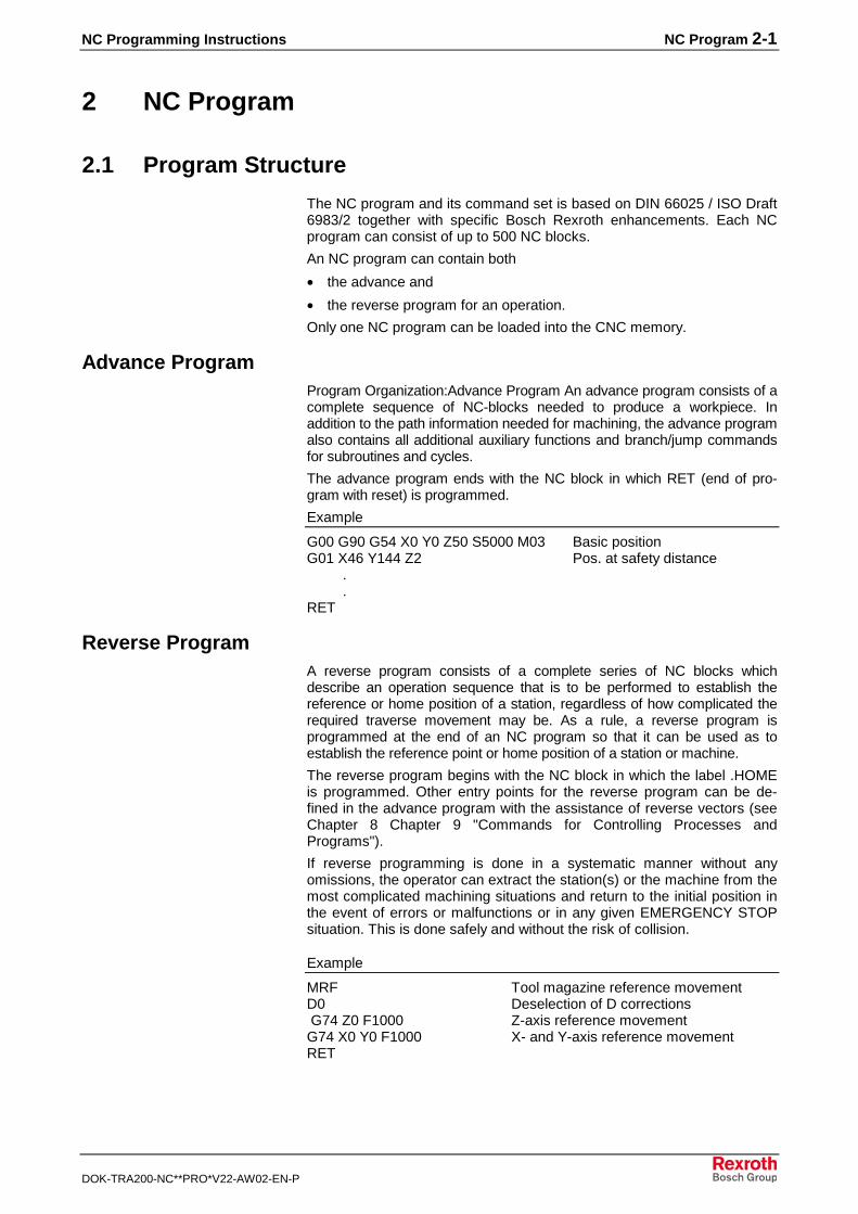
Advance ProgramProgram Organization:Advance Program An advance program consists of acomplete sequence of NC-blocks needed to produce a workpiece. Inaddition to the path information needed for machining, the advance programalso contains all additional auxiliary functions and branch/jump commandsfor subroutines and cycles.
The advance program ends with the NC block in which RET (end of pro-gram with reset) is programmed.
Example
G00 G90 G54 X0 Y0 Z50 S5000 M03 Basic positionG01 X46 Y144 Z2 Pos. at safety distance . .RET
Reverse ProgramA reverse program consists of a complete series of NC blocks whichdescribe an operation sequence that is to be performed to establish thereference or home position of a station, regardless of how complicated therequired traverse movement may be. As a rule, a reverse program isprogrammed at the end of an NC program so that it can be used as toestablish the reference point or home position of a station or machine.
The reverse program begins with the NC block in which the label .HOMEis programmed. Other entry points for the reverse program can be de-fined in the advance program with the assistance of reverse vectors (seeChapter 8 Chapter 9 "Commands for Controlling Processes andPrograms").
If reverse programming is done in a systematic manner without anyomissions, the operator can extract the station(s) or the machine from themost complicated machining situations and return to the initial position inthe event of errors or malfunctions or in any given EMERGENCY STOPsituation. This is done safely and without the risk of collision.
Example
MRF Tool magazine reference movementD0 Deselection of D corrections G74 Z0 F1000 Z-axis reference movementG74 X0 Y0 F1000 X- and Y-axis reference movementRET
2-2 NC Program NC Programming Instructions
DOK-TRA200-NC**PRO*V22-AW02-EN-P
Note: It is not necessary to program a reverse program unless themachine builder has specified in the process parameters(Bxx.032) that a reverse program must be programmed.
2.2 Elements of a NC Block
An NC block contains data to perform an operating step. The NC blockconsists of one or more words as well as the NC control commands. TheNC block length may not exceed 240 characters; it can be split in no morethan four lines.
An NC block is comprised of the following elements:
• Block number,
• Branch label,
• NC words (NC control command(s)),
• Message,
• Remark in the program, and
• Remark in the source program.
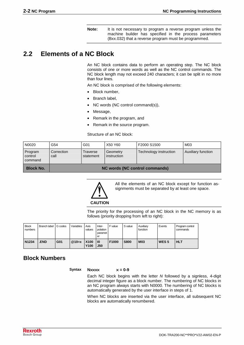
Structure of an NC block:
N0020 G54 G01 X50 Y60 F2000 S1500 M03
Programcontrolcommand
Correctioncall
Traversestatement
Geometryinstruction
Technology instruction Auxiliary function
Block No. NC words (NC control commands)
CAUTION
All the elements of an NC block except for function as-signments must be separated by at least one space.
The priority for the processing of an NC block in the NC memory is asfollows (priority dropping from left to right):
Blocknumbers
Branch label G codes Variables Axisvalues
Inter-polationparameter
F value S value Auxiliaryfunction
Events Program controlcommands
N1234 .END G01 @10=x X100Y100
I0J50
F1000 S800 M03 WES 5 HLT
Block Numbers
N×××××××××××××××× ×××× = 0-9
Each NC block begins with the letter N followed by a signless, 4-digitdecimal integer figure as a block number. The numbering of NC blocks inan NC program always starts with N0000. The numbering of NC blocks isautomatically generated by the user interface in steps of 1.
When NC blocks are inserted via the user interface, all subsequent NCblocks are automatically renumbered.
Syntax

NC Programming Instructions NC Program 2-3
DOK-TRA200-NC**PRO*V22-AW02-EN-P
2.3 NC Word
The NC-word contains the DIN 66025 instructions and various specificBosch Rexroth enhanced commands.
The NC word is divided into:
Function Enhanced commands
geometric instructions Axis positions X__ Y__
technology instructions Spindle speed, feed S__ F__
Traverse instructions Rapid traverse, circular interpolation G__ G__
Auxiliary functions Coolant M__
Override calls Tool overrides, zero points G__ G__
Enhanced functions Conditional branch/jump, calculations
Fig. 2-1: Structure of an NC word
A word is comprised of the address letter and the numerical value ofwhich the specific machine motions and auxiliary functions are to beinitiated.
The address letter is generally a text character.
The numerical value can have signs and decimal points. The sign islocated between the address letter and the numerical value. A positivesign does not need to be entered.
����������
�� �������������������������������
��������������
�
���
���
�
����
���� �� ����
25WORT.FH7
Fig. 2-2: Word structure
Example:
; Enhanced address structure for an X1 and Y1 axisG01 X1 50.45 Y1 35.456 F1000 thread position 1Z10 Z to safety distanceM103 S1 1000 1. spindle 1000 U/min
Note: There must be a blank between the address and the numericvalue to be assigned.
Address letter
Numerical value
2-4 NC Program NC Programming Instructions
DOK-TRA200-NC**PRO*V22-AW02-EN-P
The decimal point is set to achieve the resolutions shown below:
X0.00001 = 0.01 µmX0.0001 = 0.1 µmX0.001 = 1 µm
etc.Leading or following zeros can be ignored in the decimal point format.
Decimal point entry is possible in the following addresses:
Axis letters: I, J, K, P, S, F, contents of @xxx
Note: The maximum number of digits to the right of the decimalpoint which can be programmed is set in the processparameters(Bxx.002).
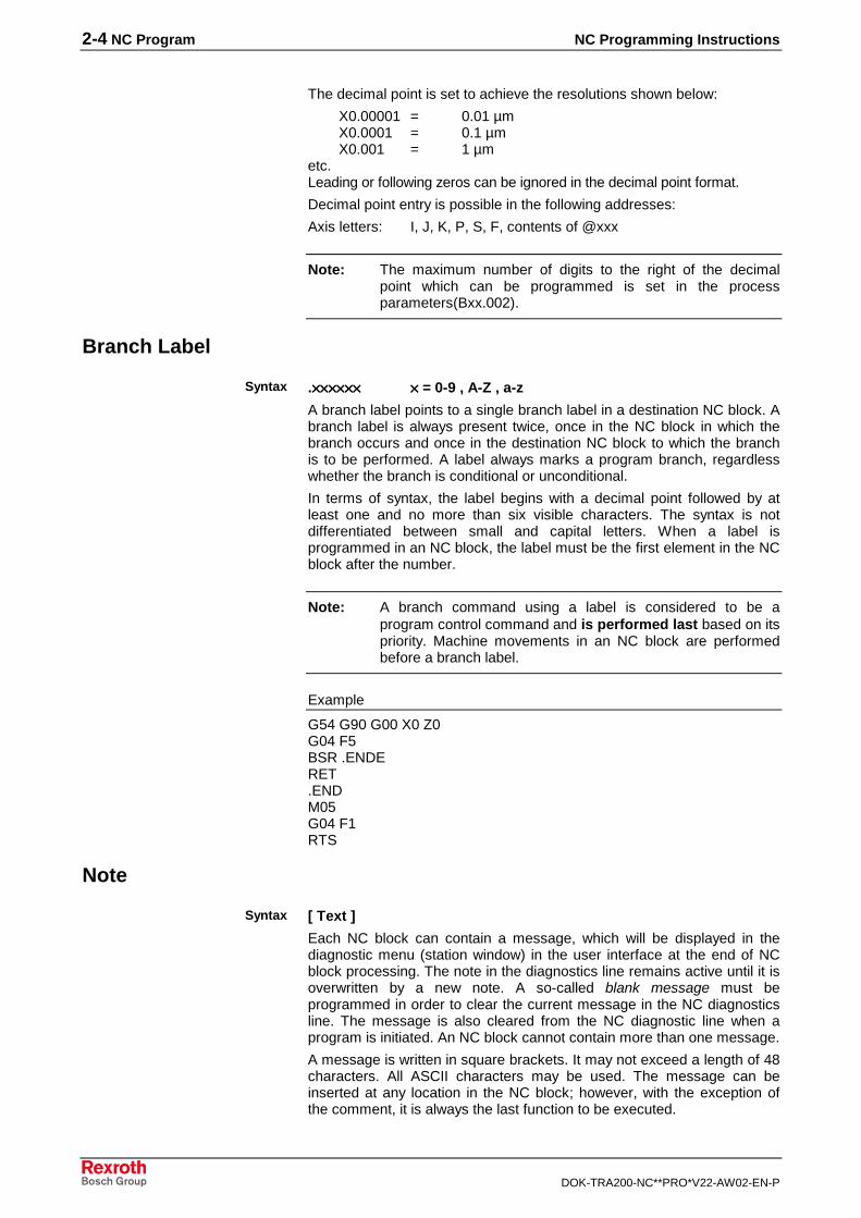
Branch Label
.×××××××××××××××××××××××× ×××× = 0-9 , A-Z , a-z
A branch label points to a single branch label in a destination NC block. Abranch label is always present twice, once in the NC block in which thebranch occurs and once in the destination NC block to which the branchis to be performed. A label always marks a program branch, regardlesswhether the branch is conditional or unconditional.
In terms of syntax, the label begins with a decimal point followed by atleast one and no more than six visible characters. The syntax is notdifferentiated between small and capital letters. When a label isprogrammed in an NC block, the label must be the first element in the NCblock after the number.
Note: A branch command using a label is considered to be aprogram control command and is performed last based on itspriority. Machine movements in an NC block are performedbefore a branch label.
Example
G54 G90 G00 X0 Z0G04 F5BSR .ENDERET.ENDM05G04 F1RTS
Note
[ Text ]
Each NC block can contain a message, which will be displayed in thediagnostic menu (station window) in the user interface at the end of NCblock processing. The note in the diagnostics line remains active until it isoverwritten by a new note. A so-called blank message must beprogrammed in order to clear the current message in the NC diagnosticsline. The message is also cleared from the NC diagnostic line when aprogram is initiated. An NC block cannot contain more than one message.
A message is written in square brackets. It may not exceed a length of 48characters. All ASCII characters may be used. The message can beinserted at any location in the NC block; however, with the exception ofthe comment, it is always the last function to be executed.
Syntax
Syntax
NC Programming Instructions NC Program 2-5
DOK-TRA200-NC**PRO*V22-AW02-EN-P
Example
G01 G54, G90 [ Traverse X to safety distance ] F1000X500[ Traverse Z to safety distance ] G01 G51 G90 F1000Z100
Comment
( Text )
Each NC block can contain a comment. A comment is written inparentheses. It may not exceed a length of 80 characters. All ASCIIcharacters may be used. The comment can be inserted at any desiredlocation in the NC block. The comment is transferred to the controllermemory and is shown in the current NC block display.
An NC block cannot contain more than one comment and one message.
Example
G00 ( Traverse X to starting position ) X150( Traverse Z to starting position) G01 Z10
Messages and hints must not be programmed between individualPreparatory G functions.
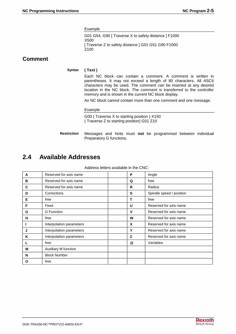
2.4 Available Addresses
Address letters available in the CNC:
A Reserved for axis name P Angle
B Reserved for axis name Q free
C Reserved for axis name R Radius
D Corrections S Spindle speed / position
E free T free
F Feed U Reserved for axis name
G G Function V Reserved for axis name
H free W Reserved for axis name
I Interpolation parameters X Reserved for axis name
J Interpolation parameters Y Reserved for axis name
K Interpolation parameters Z Reserved for axis name
L free @ Variables
M Auxiliary M function
N Block Number
O free
Syntax
Restriction

2-6 NC Program NC Programming Instructions
DOK-TRA200-NC**PRO*V22-AW02-EN-P
An expanded address syntax is provided for the following addresses:
A(1-3) Reserved for axis name B(1-3) Reserved for axis name
C(1-3) Reserved for axis name U(1-3) Reserved for axis name
V(1-3) Reserved for axis name W(1-3) Reserved for axis name
X(1-3) Reserved for axis name Y(1-3) Reserved for axis name
Z(1-3) Reserved for axis name S(1-3) Spindle speed / position
The NC syntax is not case sensitive; no distinction is made between up-per and lower case. This means that "x400" can be used instead of"X400" when programming an axis position. However, for the sake oflegibility, it is generally a good idea to write NC commands in upper casecharacters.The full ASCII character set may be used for hints and messages.
NC Programming Instructions Motion Commands, Dimension Inputs 3-1
DOK-TRA200-NC**PRO*V22-AW02-EN-P
3 Motion Commands, Dimension Inputs
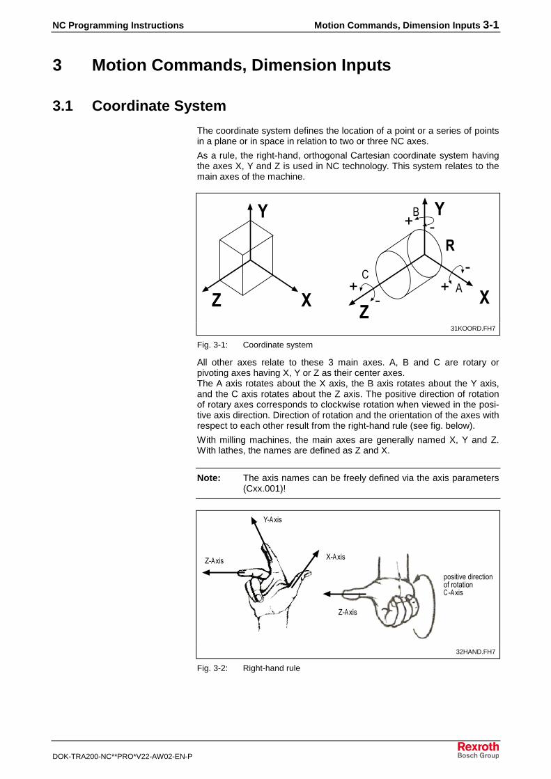
3.1 Coordinate System
The coordinate system defines the location of a point or a series of pointsin a plane or in space in relation to two or three NC axes.
As a rule, the right-hand, orthogonal Cartesian coordinate system havingthe axes X, Y and Z is used in NC technology. This system relates to themain axes of the machine.
��
�
��
�
�
�
�
��
��
�
� �
31KOORD.FH7
Fig. 3-1: Coordinate system
All other axes relate to these 3 main axes. A, B and C are rotary orpivoting axes having X, Y or Z as their center axes.The A axis rotates about the X axis, the B axis rotates about the Y axis,and the C axis rotates about the Z axis. The positive direction of rotationof rotary axes corresponds to clockwise rotation when viewed in the posi-tive axis direction. Direction of rotation and the orientation of the axes withrespect to each other result from the right-hand rule (see fig. below).
With milling machines, the main axes are generally named X, Y and Z.With lathes, the names are defined as Z and X.
Note: The axis names can be freely defined via the axis parameters(Cxx.001)!
������
����� �����
�����
���� ��������� �������� � ���������
32HAND.FH7
Fig. 3-2: Right-hand rule
3-2 Motion Commands, Dimension Inputs NC Programming Instructions
DOK-TRA200-NC**PRO*V22-AW02-EN-P
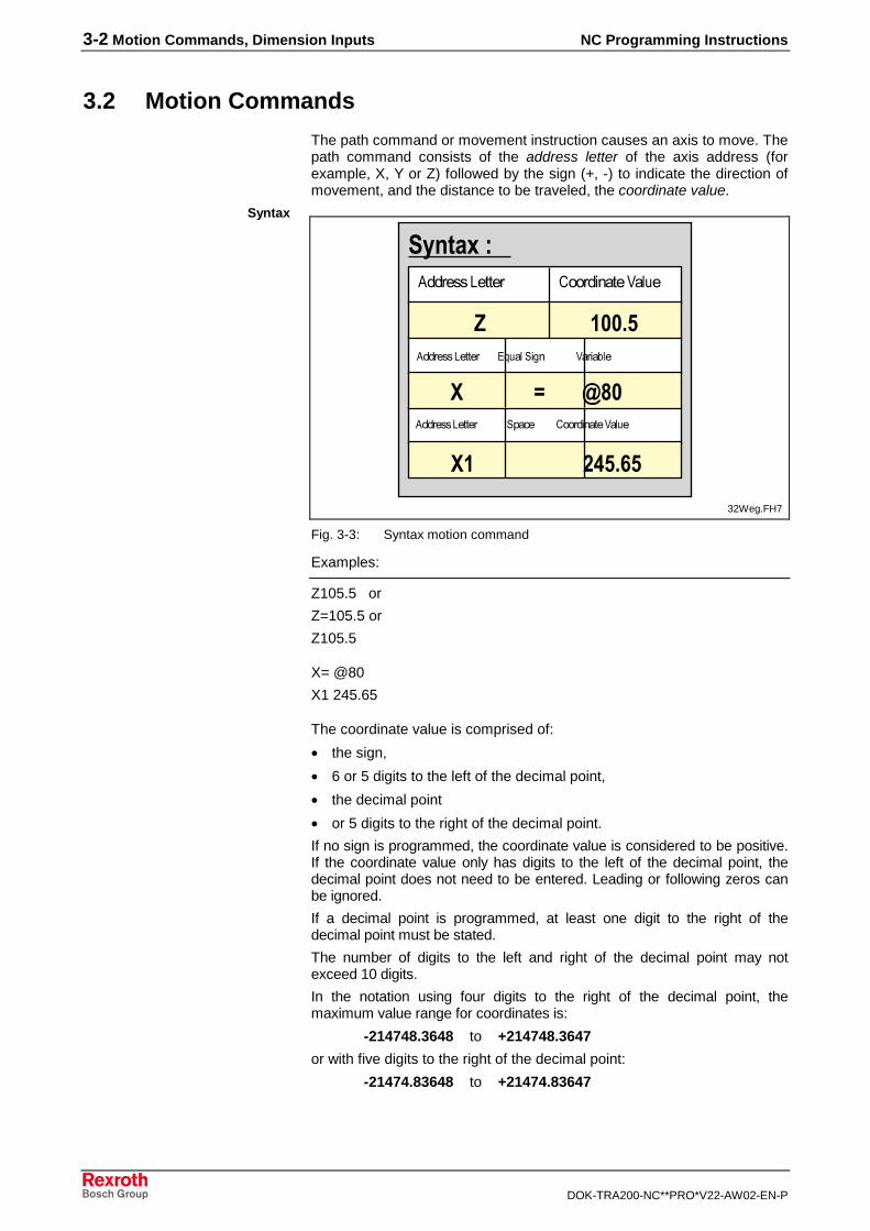
3.2 Motion Commands
The path command or movement instruction causes an axis to move. Thepath command consists of the address letter of the axis address (forexample, X, Y or Z) followed by the sign (+, -) to indicate the direction ofmovement, and the distance to be traveled, the coordinate value.
���������� ������������������������� �������
� ������
�� ����
���������� ���������������������������������������
� �����������������
�� �������������������
���������� ������������������������������������ �������
32Weg.FH7
Fig. 3-3: Syntax motion command
Examples:
Z105.5 or
Z=105.5 or
Z105.5
X= @80
X1 245.65
The coordinate value is comprised of:
• the sign,
• 6 or 5 digits to the left of the decimal point,
• the decimal point
• or 5 digits to the right of the decimal point.
If no sign is programmed, the coordinate value is considered to be positive.If the coordinate value only has digits to the left of the decimal point, thedecimal point does not need to be entered. Leading or following zeros canbe ignored.
If a decimal point is programmed, at least one digit to the right of thedecimal point must be stated.
The number of digits to the left and right of the decimal point may notexceed 10 digits.
In the notation using four digits to the right of the decimal point, themaximum value range for coordinates is:
-214748.3648 to +214748.3647
or with five digits to the right of the decimal point:
-21474.83648 to +21474.83647
Syntax
NC Programming Instructions Motion Commands, Dimension Inputs 3-3
DOK-TRA200-NC**PRO*V22-AW02-EN-P
3.3 Measurements
The path commands for the axes can be entered in two different ways:
as an absolute dimension entry (G90) or
as an incremental dimension entry (G91).
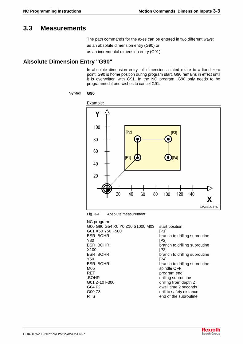
Absolute Dimension Entry "G90"In absolute dimension entry, all dimensions stated relate to a fixed zeropoint. G90 is home position during program start. G90 remains in effect untilit is overwritten with G91. In the NC program, G90 only needs to beprogrammed if one wishes to cancel G91.
G90
Example:
!
"!
#!
$!!
! %! "! #! $!! $ ! $%!�
�
&'$(
&' ( &')(
&'%(
%!
32ABSOL.FH7
Fig. 3-4: Absolute measurement
NC program:G00 G90 G54 X0 Y0 Z10 S1000 M03 start positionG01 X50 Y50 F500 [P1]BSR .BOHR branch to drilling subroutineY80 [P2]BSR .BOHR branch to drilling subroutineX100 [P3]BSR .BOHR branch to drilling subroutineY50 [P4]BSR .BOHR branch to drilling subroutineM05 spindle OFFRET program end.BOHR drilling subroutineG01 Z-10 F300 drilling from depth ZG04 F2 dwell time 2 secondsG00 Z3 drill to safety distanceRTS end of the subroutine
Syntax
3-4 Motion Commands, Dimension Inputs NC Programming Instructions
DOK-TRA200-NC**PRO*V22-AW02-EN-P
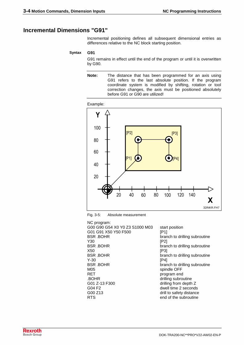
Incremental Dimensions "G91"Incremental positioning defines all subsequent dimensional entries asdifferences relative to the NC block starting position.
G91
G91 remains in effect until the end of the program or until it is overwrittenby G90.
Note: The distance that has been programmed for an axis usingG91 refers to the last absolute position. If the programcoordinate system is modified by shifting, rotation or toolcorrection changes, the axis must be positioned absolutelybefore G91 or G90 are utilized!
Example:
!
"!
#!
$!!
! %! "! #! $!! $ ! $%!�
�
&'$(
&' ( &')(
&'%(
%!
32INKR.FH7
Fig. 3-5: Absolute measurement
NC program:G00 G90 G54 X0 Y0 Z3 S1000 M03 start positionG01 G91 X50 Y50 F500 [P1]BSR .BOHR branch to drilling subroutineY30 [P2]BSR .BOHR branch to drilling subroutineX50 [P3]BSR .BOHR branch to drilling subroutineY-30 [P4]BSR .BOHR branch to drilling subroutineM05 spindle OFFRET program end.BOHR drilling subroutineG01 Z-13 F300 drilling from depth ZG04 F2 dwell time 2 secondsG00 Z13 drill to safety distanceRTS end of the subroutine
Syntax
NC Programming Instructions Motion Commands, Dimension Inputs 3-5
DOK-TRA200-NC**PRO*V22-AW02-EN-P
3.4 Zero Points
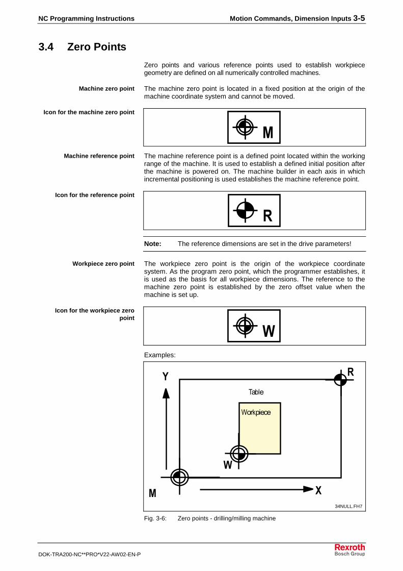
Zero points and various reference points used to establish workpiecegeometry are defined on all numerically controlled machines.
The machine zero point is located in a fixed position at the origin of themachine coordinate system and cannot be moved.
�The machine reference point is a defined point located within the workingrange of the machine. It is used to establish a defined initial position afterthe machine is powered on. The machine builder in each axis in whichincremental positioning is used establishes the machine reference point.
�
Note: The reference dimensions are set in the drive parameters!
The workpiece zero point is the origin of the workpiece coordinatesystem. As the program zero point, which the programmer establishes, itis used as the basis for all workpiece dimensions. The reference to themachine zero point is established by the zero offset value when themachine is set up.
�Examples:
� �
�
�
�
*����
+��,�����
34NULL.FH7
Fig. 3-6: Zero points - drilling/milling machine
Machine zero point
Icon for the machine zero point
Machine reference point
Icon for the reference point
Workpiece zero point
Icon for the workpiece zeropoint
3-6 Motion Commands, Dimension Inputs NC Programming Instructions
DOK-TRA200-NC**PRO*V22-AW02-EN-P
�
�
�-
35NULLD.FH7
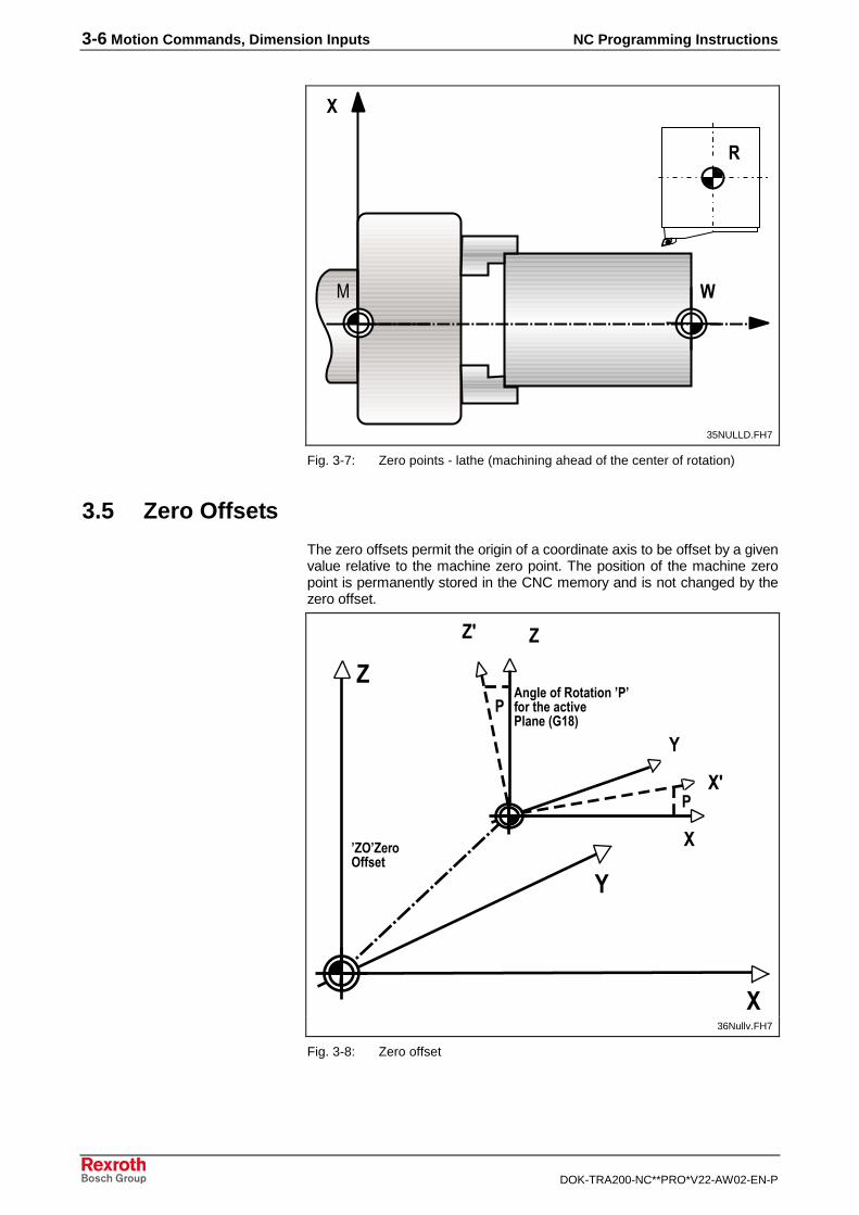
Fig. 3-7: Zero points - lathe (machining ahead of the center of rotation)
3.5 Zero Offsets
The zero offsets permit the origin of a coordinate axis to be offset by a givenvalue relative to the machine zero point. The position of the machine zeropoint is permanently stored in the CNC memory and is not changed by thezero offset.
�
�
�
�
�
�
�
��
��
������� ��� � !���"�" �#� $���% !&�������'(��)
"�*"��#�* +�
�
36Nullv.FH7
Fig. 3-8: Zero offset
NC Programming Instructions Motion Commands, Dimension Inputs 3-7
DOK-TRA200-NC**PRO*V22-AW02-EN-P
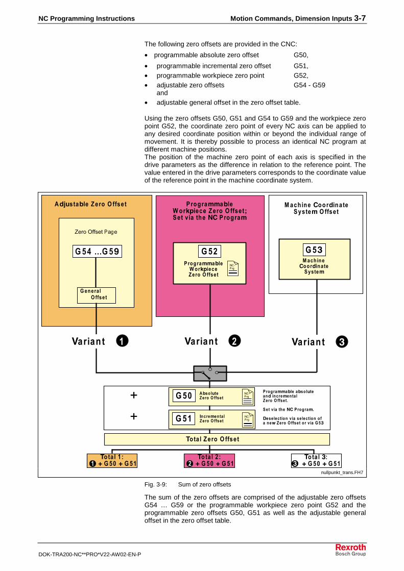
The following zero offsets are provided in the CNC:
• programmable absolute zero offset G50,
• programmable incremental zero offset G51,• programmable workpiece zero point G52,• adjustable zero offsets G54 - G59
and• adjustable general offset in the zero offset table.
Using the zero offsets G50, G51 and G54 to G59 and the workpiece zeropoint G52, the coordinate zero point of every NC axis can be applied toany desired coordinate position within or beyond the individual range ofmovement. It is thereby possible to process an identical NC program atdifferent machine positions.The position of the machine zero point of each axis is specified in thedrive parameters as the difference in relation to the reference point. Thevalue entered in the drive parameters corresponds to the coordinate valueof the reference point in the machine coordinate system.
( ,
�����-�!��#
* +� ( ���#� �* +�
����.���� �'���
� �%$!��.��#/!�� �
�+ �-
( �
�#��#�--!�#0�#�#� �#1+ 2%1�3��43�1
�� /���0�������1��'�����22�#��#�--�0��
� �#14!�%���#� �* +�
�0+� �3 ���#� �* +� ( �
5�%#�-�� � ���#� �* +� ( �
�#��#�--�0�� ��0+� �3 ���/�!�%#�-�� � ���#� �* +� �
� �& !� � $� �6.��#��#�-�
7�+���% !�� �& !� �+� ��% !�� �� � ���8���#� �* +� �� #�& !� �( ,
9� � ����#� �* +�
� #��#�--�0��� �#14!�%����#� �* +� :� �& !� � $��6.��#��#�-
�/;3+ �0�� ���#� �* +� � �%$ !���.��#/!�� ��+ �-�* +�
( �1��'��
1��'��
1��'��
�
�
( ,
<�#!�� �
9� � ��� �������=�( ��=�( ��
9� � ��� �������=�( ��=�( ��
9� � ��,�������=�( ��=�( �,
<�#!�� � <�#!�� ,
( �����( >
nullpunkt_trans.FH7
Fig. 3-9: Sum of zero offsets
The sum of the zero offsets are comprised of the adjustable zero offsetsG54 … G59 or the programmable workpiece zero point G52 and theprogrammable zero offsets G50, G51 as well as the adjustable generaloffset in the zero offset table.
3-8 Motion Commands, Dimension Inputs NC Programming Instructions
DOK-TRA200-NC**PRO*V22-AW02-EN-P
Note: The programmable zero offsets G50 and G51 become inactiveduring the programming of G52, G53, G54 - G59.
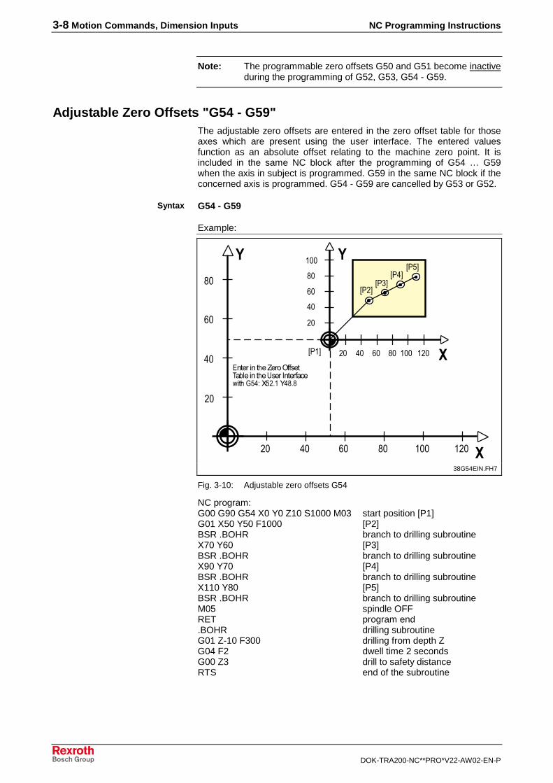
Adjustable Zero Offsets "G54 - G59"The adjustable zero offsets are entered in the zero offset table for thoseaxes which are present using the user interface. The entered valuesfunction as an absolute offset relating to the machine zero point. It isincluded in the same NC block after the programming of G54 … G59when the axis in subject is programmed. G59 in the same NC block if theconcerned axis is programmed. G54 - G59 are cancelled by G53 or G52.
G54 - G59
Example:
�
�
!
%!
"!
#!
$!!
! %! "! #! $!! $ !
!
%!
"!
#!
! %! "! #! $!! $ !
&'$(
&' (&')(
&'%(&'3(
�� ������ 4������.���� *�������� 4��5����6� ������7� 4�83%9�3 :$��%#:#
�
�
38G54EIN.FH7
Fig. 3-10: Adjustable zero offsets G54
NC program:G00 G90 G54 X0 Y0 Z10 S1000 M03 start position [P1]G01 X50 Y50 F1000 [P2]BSR .BOHR branch to drilling subroutineX70 Y60 [P3]BSR .BOHR branch to drilling subroutineX90 Y70 [P4]BSR .BOHR branch to drilling subroutineX110 Y80 [P5]BSR .BOHR branch to drilling subroutineM05 spindle OFFRET program end.BOHR drilling subroutineG01 Z-10 F300 drilling from depth ZG04 F2 dwell time 2 secondsG00 Z3 drill to safety distanceRTS end of the subroutine
Syntax
NC Programming Instructions Motion Commands, Dimension Inputs 3-9
DOK-TRA200-NC**PRO*V22-AW02-EN-P
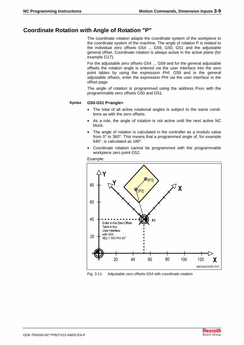
Coordinate Rotation with Angle of Rotation "P"The coordinate rotation adapts the coordinate system of the workpiece tothe coordinate system of the machine. The angle of rotation P is related tothe individual zero offsets G54 ... G59, G50, G51 and the adjustablegeneral offset. Coordinate rotation is always active in the active plane (forexample G17).
For the adjustable zero offsets G54 … G59 and for the general adjustableoffsets the rotation angle is entered via the user interface into the zeropoint tables by using the expression PHI. G59 and in the generaladjustable offsets, enter the expression PHI via the user interface in theoffset page.
The angle of rotation is programmed using the address Pxxx with theprogrammable zero offsets G50 and G51.
G50-G51 P<angle>
• The total of all active rotational angles is subject to the same condi-tions as with the zero offsets.
• As a rule, the angle of rotation is not active until the next active NCblock.
• The angle of rotation is calculated in the controller as a modulo valuefrom 0° to 360°. This means that a programmed angle of, for example540°, is calculated as 180°.
• Coordinate rotation cannot be programmed with the programmableworkpiece zero point G52.
Example:
�
�
!
%!
"!
#!
! %! "! #! $!! $ !
��
��
&' (
&')(
�� ������ 4������.���� *�������� 4�5����6� ������7� 4�83%�93 :$��%!�';6�%3<
39G54KOOR.FH7
Fig. 3-11: Adjustable zero offsets G54 with coordinate rotation
Syntax
3-10 Motion Commands, Dimension Inputs NC Programming Instructions
DOK-TRA200-NC**PRO*V22-AW02-EN-P
NC program:G00 G90 G54 X0 Y0 Z10 S1000 M03 start position [P1]G01 X40 Y70 F800 [P2]BSR .BOHR branch to drilling subroutineX80 [P3]BSR .BOHR branch to drilling subroutineM05 spindle OFFRET.BOHR drilling subroutineG01 Z-10 F300 drilling from depth ZG04 F2 dwell time 2 secondsG00 Z3 drill to safety distanceRTS end of the subroutine
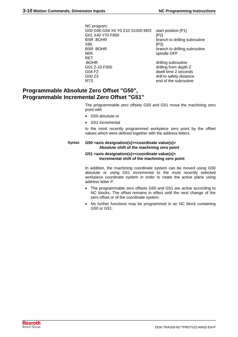
Programmable Absolute Zero Offset "G50",Programmable Incremental Zero Offset "G51"
The programmable zero offsets G50 and G51 move the machining zeropoint with
• G50 absolute or
• G51 incremental
to the most recently programmed workpiece zero point by the offsetvalues which were defined together with the address letters.
G50 <axis designation(s)><coordinate value(s)>Absolute shift of the machining zero point
G51 <axis designation(s)><coordinate value(s)>Incremental shift of the machining zero point
In addition, the machining coordinate system can be moved using G50absolute or using G51 incremental to the most recently selectedworkpiece coordinate system in order to rotate the active plane usingaddress letter P.
• The programmable zero offsets G50 and G51 are active according toNC blocks. The offset remains in effect until the next change of thezero offset or of the coordinate system.
• No further functions may be programmed in an NC block containingG50 or G51.
Syntax
NC Programming Instructions Motion Commands, Dimension Inputs 3-11
DOK-TRA200-NC**PRO*V22-AW02-EN-P
Example:
�
�
�
�
�
�
!
%!
"!
#!
! %! "! #! $!! $ !
!
%!
"!
#!
$!!
! %! "! #! $!!
!
%!
"!
#!
$!!
! %! "! #! $!!
��
��
�� �,
��
(�����������
�
����
312G50.FH7
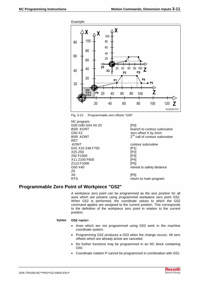
Fig. 3-12: Programmable zero offsets "G50"
NC program:G00 G90 G54 X0 Z0 [P0]BSR .KONT branch to contour subroutineG50 X2 zero offset X by 2mmBSR .KONT 2nd
call of contour subroutineRET.KONT contour subroutineG01 X10 Z48 F750 [P1]X25 Z59 [P2]Z92 F1500 [P3]X11 Z100 F600 [P4]Z113 F1000 [P5]G00 X40 retreat to safety distanceZ0X0 [P0]RTS return to main program
Programmable Zero Point of Workpiece "G52"A workpiece zero point can be programmed as the axis position for allaxes which are present using programmed workpiece zero point G52.When G52 is performed, the coordinate values to which the G52command applies are assigned to the current position. This correspondsto the definition of the workpiece zero point in relation to the currentposition.
G52 <axis>
• Axes which are not programmed using G52 work in the machinecoordinate system.
• Programming G52 produces a G53 when the change occurs. All zerooffsets which are already active are canceled.
• No further functions may be programmed in an NC block containingG50.
• Coordinate rotation P cannot be programmed in combination with G52.
Syntax
3-12 Motion Commands, Dimension Inputs NC Programming Instructions
DOK-TRA200-NC**PRO*V22-AW02-EN-P
Example:
�
!
%!
"!
#!
! %! #! $!! $ ! �
&'#(
(���?@����A� #��!�� $����#��* +� �9�0��8! $�8�3�/�0��(���>���,�
(��������*?9�0�������,�
�
!
%!
"!
#!
$!!
! %! "! #! $!!
�
�
!
%!
"!
#!
$!!
! %! "! #! $!!
�
B��C
B��C
B�,CB��C
B�C
B��C
B��C
B�,CB��C
B�C
"!312G52.FH7
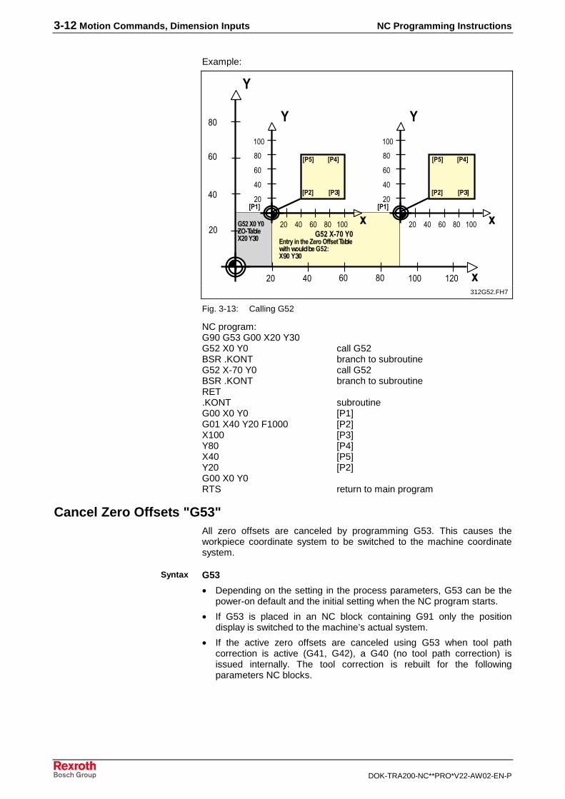
Fig. 3-13: Calling G52
NC program:G90 G53 G00 X20 Y30G52 X0 Y0 call G52BSR .KONT branch to subroutineG52 X-70 Y0 call G52BSR .KONT branch to subroutineRET.KONT subroutineG00 X0 Y0 [P1]G01 X40 Y20 F1000 [P2]X100 [P3]Y80 [P4]X40 [P5]Y20 [P2]G00 X0 Y0RTS return to main program
Cancel Zero Offsets "G53"All zero offsets are canceled by programming G53. This causes theworkpiece coordinate system to be switched to the machine coordinatesystem.
G53
• Depending on the setting in the process parameters, G53 can be thepower-on default and the initial setting when the NC program starts.
• If G53 is placed in an NC block containing G91 only the positiondisplay is switched to the machine’s actual system.
• If the active zero offsets are canceled using G53 when tool pathcorrection is active (G41, G42), a G40 (no tool path correction) isissued internally. The tool correction is rebuilt for the followingparameters NC blocks.
Syntax
NC Programming Instructions Motion Commands, Dimension Inputs 3-13
DOK-TRA200-NC**PRO*V22-AW02-EN-P
Adjustable General Offset in the Zero Offset TableBy having the general adjustable offset in the zero offset table, the CNCcan also offset the workpiece zero point in addition to the adjustable andprogrammable zero offsets. The adjustable general offset functions in anadditive manner to the adjustable and programmable zero offsets. Thismeans that the adjustable general offset does not become active until oneof the adjustable or programmable zero offsets has been activated.
• The adjustable general offset is canceled using G53 and is notcalculated until a zero offset is selected again.
• An angle of rotation can be entered into the zero offset table using theaddress PHI. This angle is added to the already active angles ofrotation.
• The adjustable general offset can never be active alone due to theconditions described above.
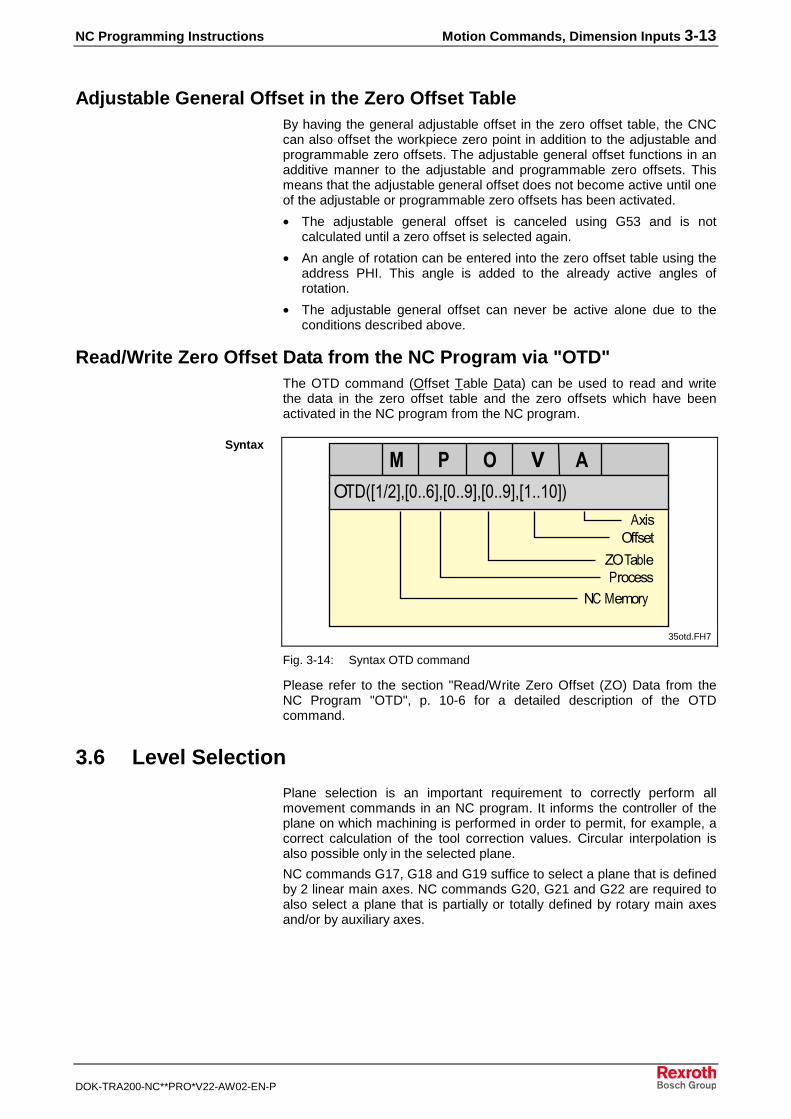
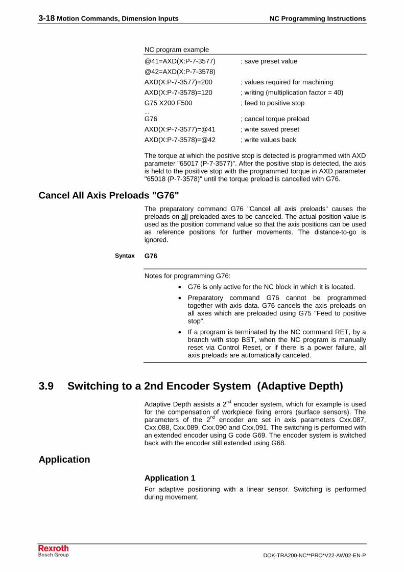
Read/Write Zero Offset Data from the NC Program via "OTD"The OTD command (Offset Table Data) can be used to read and writethe data in the zero offset table and the zero offsets which have beenactivated in the NC program from the NC program.
.*=>&$? (@&!::"(@&!::A(@&!::A(@&$::$!(B
�����������������*�������<��������
����.����
.�*����'������
1��-�2��C
35otd.FH7
Fig. 3-14: Syntax OTD command
Please refer to the section "Read/Write Zero Offset (ZO) Data from theNC Program "OTD", p. 10-6 for a detailed description of the OTDcommand.
3.6 Level Selection
Plane selection is an important requirement to correctly perform allmovement commands in an NC program. It informs the controller of theplane on which machining is performed in order to permit, for example, acorrect calculation of the tool correction values. Circular interpolation isalso possible only in the selected plane.
NC commands G17, G18 and G19 suffice to select a plane that is definedby 2 linear main axes. NC commands G20, G21 and G22 are required toalso select a plane that is partially or totally defined by rotary main axesand/or by auxiliary axes.
Syntax
3-14 Motion Commands, Dimension Inputs NC Programming Instructions
DOK-TRA200-NC**PRO*V22-AW02-EN-P
Axis Number, Axis Designation and Axis Meaning
Each axis has an axis number (1, ... 7 ), an axis designation and an axismeaning (X,Y,Z,A,B,C,U,V,W,S)During parameter value assignment, an axis number and an axismeaning is determined for each axis.
Example:
Axis parameter for axis number 7C07.001 Axis designation 1 X1C07.053 Axis meaning (axis functionality) X
The following notation is used for this:axis designation(axis meaning)
Example:
B(X) means: The axis with an axis designation of B hasan axis meaning of X.
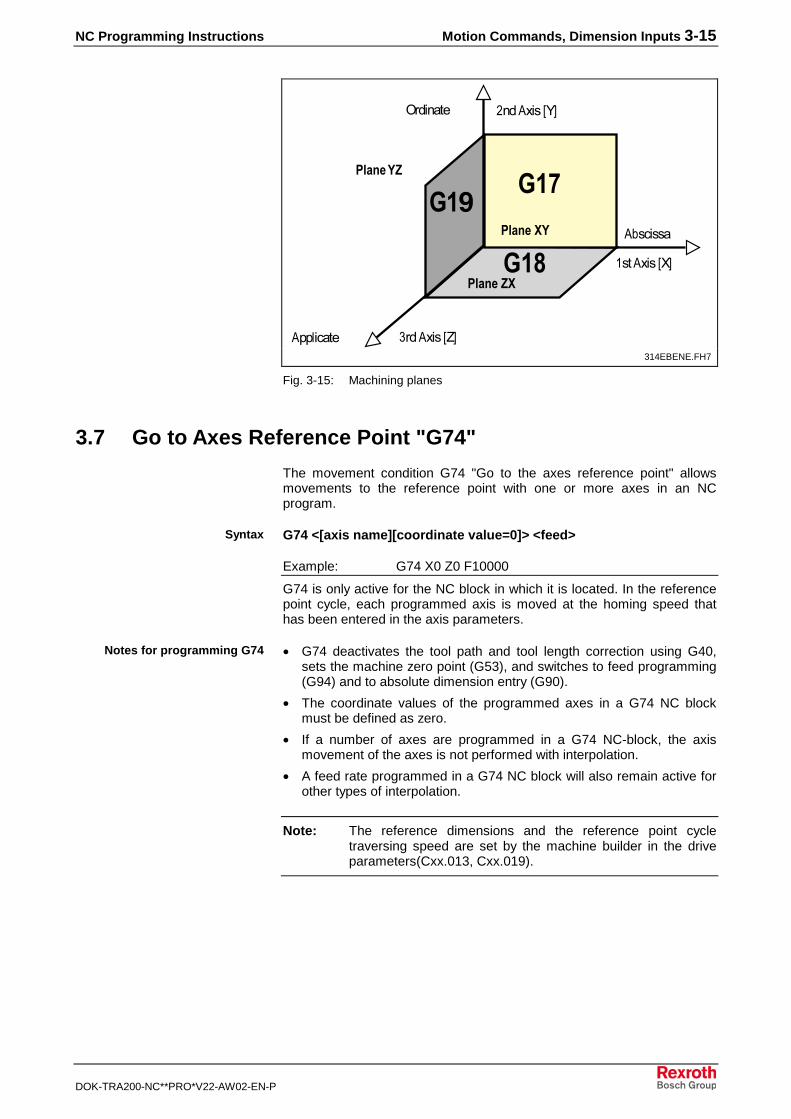
Plane Selection "G17", "G18", "G19"
G17G18G19
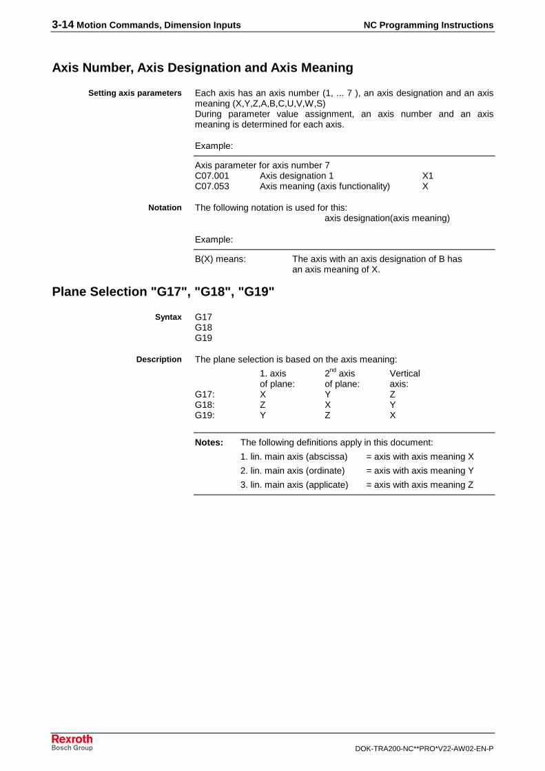
The plane selection is based on the axis meaning:
1. axis 2nd axis Vertical
of plane: of plane: axis:G17: X Y ZG18: Z X YG19: Y Z X
Notes: The following definitions apply in this document:
1. lin. main axis (abscissa) = axis with axis meaning X
2. lin. main axis (ordinate) = axis with axis meaning Y
3. lin. main axis (applicate) = axis with axis meaning Z
Setting axis parameters
Notation
Syntax
Description
NC Programming Instructions Motion Commands, Dimension Inputs 3-15
DOK-TRA200-NC**PRO*V22-AW02-EN-P
(�@
(��
(�>
$� ������&(
��������&�(
)��������&(
��������
.����� �
������� �
��������
��������
��������
314EBENE.FH7
Fig. 3-15: Machining planes
3.7 Go to Axes Reference Point "G74"
The movement condition G74 "Go to the axes reference point" allowsmovements to the reference point with one or more axes in an NCprogram.
G74 <[axis name][coordinate value=0]> <feed>
Example: G74 X0 Z0 F10000
G74 is only active for the NC block in which it is located. In the referencepoint cycle, each programmed axis is moved at the homing speed thathas been entered in the axis parameters.
• G74 deactivates the tool path and tool length correction using G40,sets the machine zero point (G53), and switches to feed programming(G94) and to absolute dimension entry (G90).
• The coordinate values of the programmed axes in a G74 NC blockmust be defined as zero.
• If a number of axes are programmed in a G74 NC-block, the axismovement of the axes is not performed with interpolation.
• A feed rate programmed in a G74 NC block will also remain active forother types of interpolation.
Note: The reference dimensions and the reference point cycletraversing speed are set by the machine builder in the driveparameters(Cxx.013, Cxx.019).
Syntax
Notes for programming G74
3-16 Motion Commands, Dimension Inputs NC Programming Instructions
DOK-TRA200-NC**PRO*V22-AW02-EN-P
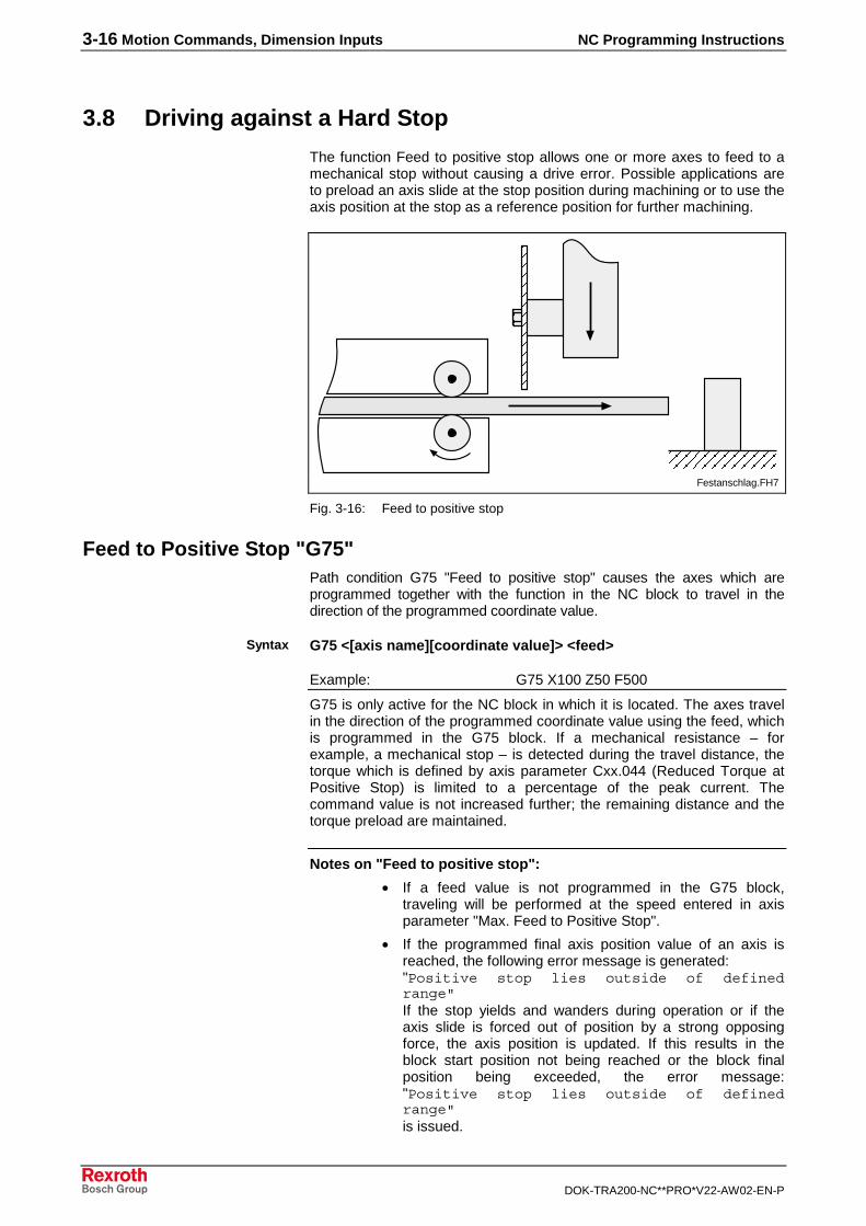
3.8 Driving against a Hard Stop
The function Feed to positive stop allows one or more axes to feed to amechanical stop without causing a drive error. Possible applications areto preload an axis slide at the stop position during machining or to use theaxis position at the stop as a reference position for further machining.
Festanschlag.FH7
Fig. 3-16: Feed to positive stop
Feed to Positive Stop "G75"Path condition G75 "Feed to positive stop" causes the axes which areprogrammed together with the function in the NC block to travel in thedirection of the programmed coordinate value.
G75 <[axis name][coordinate value]> <feed>
Example: G75 X100 Z50 F500
G75 is only active for the NC block in which it is located. The axes travelin the direction of the programmed coordinate value using the feed, whichis programmed in the G75 block. If a mechanical resistance – forexample, a mechanical stop – is detected during the travel distance, thetorque which is defined by axis parameter Cxx.044 (Reduced Torque atPositive Stop) is limited to a percentage of the peak current. Thecommand value is not increased further; the remaining distance and thetorque preload are maintained.
Notes on "Feed to positive stop":
• If a feed value is not programmed in the G75 block,traveling will be performed at the speed entered in axisparameter "Max. Feed to Positive Stop".
• If the programmed final axis position value of an axis isreached, the following error message is generated:"Positive stop lies outside of definedrange"If the stop yields and wanders during operation or if theaxis slide is forced out of position by a strong opposingforce, the axis position is updated. If this results in theblock start position not being reached or the block finalposition being exceeded, the error message:"Positive stop lies outside of definedrange"is issued.
Syntax
NC Programming Instructions Motion Commands, Dimension Inputs 3-17
DOK-TRA200-NC**PRO*V22-AW02-EN-P
• The dimensional information in a G75 NC block can beentered in absolute mode (G90) or incremental mode(G91).
• If a number of axes are programmed in a G74 NC block,the axis movement of the axes is not performed withinterpolation.
• The stop axis may not be moved between the calls of G75and G76.
Parameters Cxx.044 "Reduced Torque at Positive Stop" andCxx.045 "Max. Speed to Positive Stop" are set by the machinemanufacturer in the axis parameters.
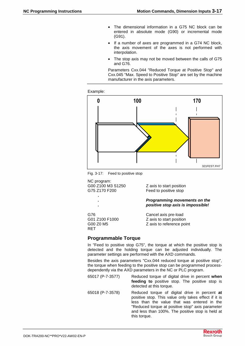
Example:
� ��� �@�
) $D
�� :�4E
321FEST.FH7
Fig. 3-17: Feed to positive stop
NC program:G00 Z100 M3 S1250 Z axis to start positionG75 Z170 F200 Feed to positive stop . . Programming movements on the . positive stop axis is impossible!
G76 Cancel axis pre-loadG01 Z100 F1000 Z axis to start positionG00 Z0 M5 Z axis to reference pointRET
Programmable TorqueIn "Feed to positive stop G75", the torque at which the positive stop isdetected and the holding torque can be adjusted individually. Theparameter settings are performed with the AXD commands.
Besides the axis parameters "Cxx.044 reduced torque at positive stop",the torque when feeding to the positive stop can be programmed process-dependently via the AXD parameters in the NC or PLC program.
65017 (P-7-3577) Reduced torque of digital drive in percent whenfeeding to positive stop. The positive stop isdetected at this torque.
65018 (P-7-3578) Reduced torque of digital drive in percent atpositive stop. This value only takes effect if it isless than the value that was entered in the"Reduced torque at positive stop" axis parameterand less than 100%. The positive stop is held atthis torque.
3-18 Motion Commands, Dimension Inputs NC Programming Instructions
DOK-TRA200-NC**PRO*V22-AW02-EN-P
NC program example
@41=AXD(X:P-7-3577) ; save preset value
@42=AXD(X:P-7-3578)
AXD(X:P-7-3577)=200 ; values required for machining
AXD(X:P-7-3578)=120 ; writing (multiplication factor = 40)
G75 X200 F500 ; feed to positive stop...G76 ; cancel torque preload
AXD(X:P-7-3577)=@41 ; write saved preset
AXD(X:P-7-3578)=@42 ; write values back
The torque at which the positive stop is detected is programmed with AXDparameter "65017 (P-7-3577)". After the positive stop is detected, the axisis held to the positive stop with the programmed torque in AXD parameter"65018 (P-7-3578)" until the torque preload is cancelled with G76.
Cancel All Axis Preloads "G76"The preparatory command G76 "Cancel all axis preloads" causes thepreloads on all preloaded axes to be canceled. The actual position value isused as the position command value so that the axis positions can be usedas reference positions for further movements. The distance-to-go isignored.
G76
Notes for programming G76:
• G76 is only active for the NC block in which it is located.
• Preparatory command G76 cannot be programmedtogether with axis data. G76 cancels the axis preloads onall axes which are preloaded using G75 "Feed to positivestop".
• If a program is terminated by the NC command RET, by abranch with stop BST, when the NC program is manuallyreset via Control Reset, or if there is a power failure, allaxis preloads are automatically canceled.
3.9 Switching to a 2nd Encoder System (Adaptive Depth)
Adaptive Depth assists a 2nd encoder system, which for example is used
for the compensation of workpiece fixing errors (surface sensors). Theparameters of the 2nd
encoder are set in axis parameters Cxx.087,Cxx.088, Cxx.089, Cxx.090 and Cxx.091. The switching is performed withan extended encoder using G code G69. The encoder system is switchedback with the encoder still extended using G68.
Application
Application 1For adaptive positioning with a linear sensor. Switching is performedduring movement.
Syntax
NC Programming Instructions Motion Commands, Dimension Inputs 3-19
DOK-TRA200-NC**PRO*V22-AW02-EN-P
Application 2To switch from a motor encoder to an external measuring system. Theexternal measuring system can either be a linear encoder, a rotationencoder for circular axes, or a linear sensor. Switching is performed in astandstill condition, but under power and with controller release.
New Axis ParameterFurther axis parameters are offered when switching to a 2nd
encodersystem if Motor encoder was preselected in the axis parameter "Positionencoder setup".
• Cxx.087 Adaptive Control
• Cxx.088 Reference value of the 2nd sensor system
• Cxx.089 Positive travel limits of the 2nd sensor system
• Cxx.090 Negative travel limits of the 2nd sensor system
• Cxx.091 Permissible sensor deflection in the 1st sensor system
G Codes to Switch to a 2nd Encoder SystemTwo new G codes are introduced to switch between both encodersystems.
• G69 switches to the 2nd encoder
• G68 switches back to the motor encoder.
The G codes are modally inactive.
A switch to the 2nd encoder is performed under a standstill condition if G
code G69 is cancelled when G09 was preselected. In the 2nd encoder
system, the axis coordinate value is being approached as the targetposition when G08 is preselected.
Example:
G69 G09 X0 ;Switching in standstill condition
G69 G08 X200 ;Move to target position in encoder system 2
Note: For detailed information, please refer to the separatelyavailable documentation "Adaptive Depth", DOK-CONTRL-AD*DPTH*V22-FKxx-EN-P.
3-20 Motion Commands, Dimension Inputs NC Programming Instructions
DOK-TRA200-NC**PRO*V22-AW02-EN-P
NC Programming Instructions Motion Blocks 4-1
DOK-TRA200-NC**PRO*V22-AW02-EN-P
4 Motion Blocks
4.1 Axes
Linear Main AxesThe linear main axes span a Cartesian coordinate system.
They are identified by means of axis names:• 1. linear main axis (symbol: X)
• 2. linear main axis (symbol: Y)
• 3. linear main axis (symbol: Z)
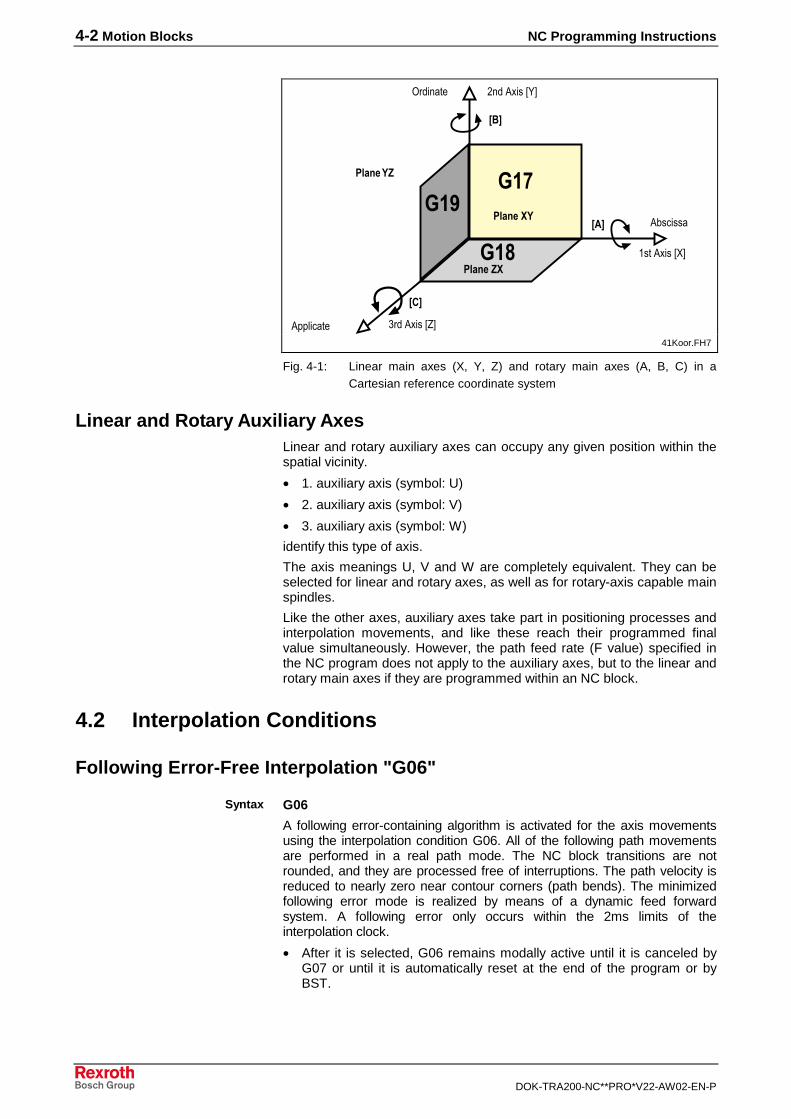
The axis name (address of the axis as it is to be addressed in the NCprogram) is freely selectable; however, the meaning of the axis is definedby the position of the axis in the coordinate system (see next fig. "Linearmain axes", sequence "Rotary main axes"). Circular interpolations and thetool radius path correction can only be performed within the machiningplanes spanned by the linear main axes (plane selection with G17, G18,G19).
Rotary Main AxesRotary main axes rotate about the linear main axes.
The axis meanings:• 1. rotary main axis (symbol: A)
• 2. rotary main axis (symbol: B)
• 3. rotary main axis (symbol: C)
indicate which coordinate axis the respective rotary main axis rotatesaround (see Fig. next fig. "Linear main axes"). The axis name (theaddress of the axis) is freely selectable; however, the axis meaning isdefined by the position of the axis in the coordinate system. With absolutepositioning (G90), the traverse range is ± 360.000 degrees. With absolutepositioning (G90), the position which is programmed in an absolutestatement is traversed via the shortest possible path. With incrementalpositioning (G91) the traverse range is ±999999.9999 degrees or±99999.99999 degrees (depending on the parameter setting). The signindicates the traverse direction.
4-2 Motion Blocks NC Programming Instructions
DOK-TRA200-NC**PRO*V22-AW02-EN-P
���
���
���
����������
�� ��������
�� ��������
��������
�� �����
���������
�����
������
���� �
���
���
���
41Koor.FH7
Fig. 4-1: Linear main axes (X, Y, Z) and rotary main axes (A, B, C) in aCartesian reference coordinate system
Linear and Rotary Auxiliary AxesLinear and rotary auxiliary axes can occupy any given position within thespatial vicinity.
• 1. auxiliary axis (symbol: U)
• 2. auxiliary axis (symbol: V)
• 3. auxiliary axis (symbol: W)
identify this type of axis.
The axis meanings U, V and W are completely equivalent. They can beselected for linear and rotary axes, as well as for rotary-axis capable mainspindles.
Like the other axes, auxiliary axes take part in positioning processes andinterpolation movements, and like these reach their programmed finalvalue simultaneously. However, the path feed rate (F value) specified inthe NC program does not apply to the auxiliary axes, but to the linear androtary main axes if they are programmed within an NC block.
4.2 Interpolation Conditions
Following Error-Free Interpolation "G06"
G06
A following error-containing algorithm is activated for the axis movementsusing the interpolation condition G06. All of the following path movementsare performed in a real path mode. The NC block transitions are notrounded, and they are processed free of interruptions. The path velocity isreduced to nearly zero near contour corners (path bends). The minimizedfollowing error mode is realized by means of a dynamic feed forwardsystem. A following error only occurs within the 2ms limits of theinterpolation clock.
• After it is selected, G06 remains modally active until it is canceled byG07 or until it is automatically reset at the end of the program or byBST.
Syntax
NC Programming Instructions Motion Blocks 4-3
DOK-TRA200-NC**PRO*V22-AW02-EN-P
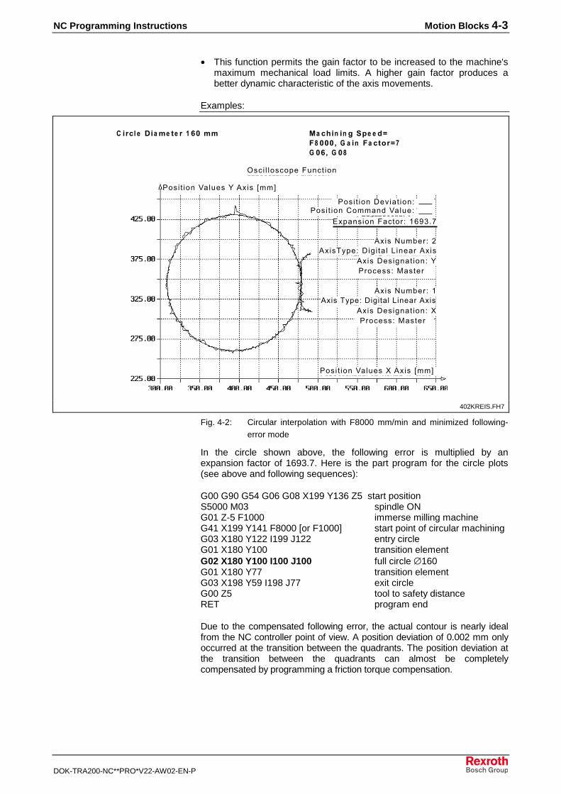
• This function permits the gain factor to be increased to the machine'smaximum mechanical load limits. A higher gain factor produces abetter dynamic characteristic of the axis movements.
Examples:
���� � ���������� ���
���� �������� ���� ���� ����������������
����������� ��� ������
���� ��������� !��� "��#
�� ��� � ���� ���� ���� � � � � � �� � !"��� �#� � � ��
!�������$�� ���� %��������&�� ��
!���'��(��� �!���)*�����$� ��+�����!���
!�������$�� ���� ��������&�� ��
!���)*�����$� � � + �����!���!���'��(��� ,
���� ���������%!��� "��#
� �"�� �$�� % " � � #��%%
����
��������
402KREIS.FH7
Fig. 4-2: Circular interpolation with F8000 mm/min and minimized following-error mode
In the circle shown above, the following error is multiplied by anexpansion factor of 1693.7. Here is the part program for the circle plots(see above and following sequences):
G00 G90 G54 G06 G08 X199 Y136 Z5 start positionS5000 M03 spindle ONG01 Z-5 F1000 immerse milling machineG41 X199 Y141 F8000 [or F1000] start point of circular machiningG03 X180 Y122 I199 J122 entry circleG01 X180 Y100 transition elementG02 X180 Y100 I100 J100 full circle ∅160G01 X180 Y77 transition elementG03 X198 Y59 I198 J77 exit circleG00 Z5 tool to safety distanceRET program end
Due to the compensated following error, the actual contour is nearly idealfrom the NC controller point of view. A position deviation of 0.002 mm onlyoccurred at the transition between the quadrants. The position deviation atthe transition between the quadrants can almost be completelycompensated by programming a friction torque compensation.
4-4 Motion Blocks NC Programming Instructions
DOK-TRA200-NC**PRO*V22-AW02-EN-P
���� � ���������� ���
���� �������� ����
���� ��������������������������� ��� ������
� � � � �� � !"��� �#� � � ��
�� ��� � ���� ���� ���
����
��������
� !&� �! �$ '�� �!� �"�� � � � �!('� � )� �! � � �*)� �"� � +"� &� �!
���� ��������!��� "��#
���� ��������!���%"��#
403Kreis.FH7
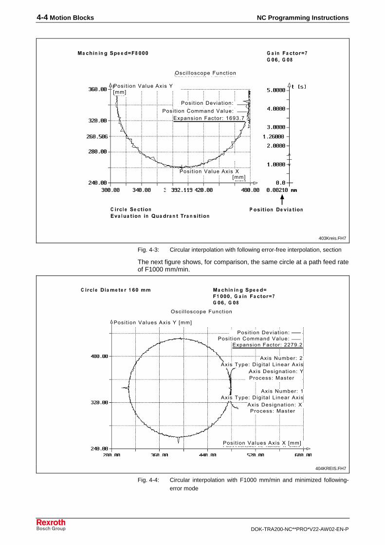
Fig. 4-3: Circular interpolation with following error-free interpolation, section
The next figure shows, for comparison, the same circle at a path feed rateof F1000 mm/min.
���� � ���������� ���
���� �������� ���� ���� ����������������
����������� ���,,���,
���� ���������!��� "��#
�� ��� � ���� ���� ���� � � � � � �� � !"��� �#� � � ��
!�������$�� ���� %��������&�� ��
!���'��(��� �!���)*�����$� � � + �����!���
!�������$�� ���� ��������&�� ��
!���)*�����$� � � + �����!���!���'��(��� ,
���� ���������!���%"��#
� �"�� �$�� % " � � #��%%
����
��������
404KREIS.FH7
Fig. 4-4: Circular interpolation with F1000 mm/min and minimized following-error mode
NC Programming Instructions Motion Blocks 4-5
DOK-TRA200-NC**PRO*V22-AW02-EN-P
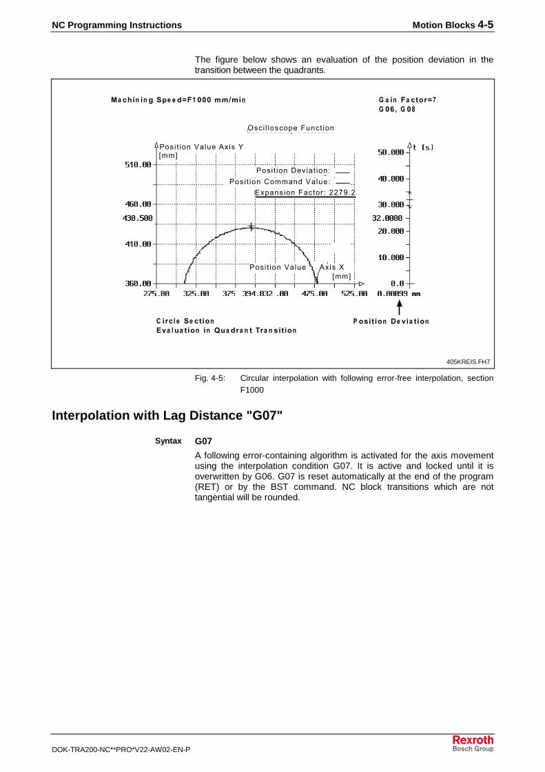
The figure below shows an evaluation of the position deviation in thetransition between the quadrants.
���� � ���������� ���
���� �������� ����
���� ��������������������������� ��� ,,���,
� � � � �� � !"��� �#� � � ��
���� ��������
�� ��� � ���� ���� ����%%,%�����
��������
� !&� �! �$ '�� �!� �"�� � � � �!('� � )� �! � � �*)� �"� � +"� &� �!
!���%
���� ��������!��� "��#
"��#
405KREIS.FH7
Fig. 4-5: Circular interpolation with following error-free interpolation, sectionF1000
Interpolation with Lag Distance "G07"
G07
A following error-containing algorithm is activated for the axis movementusing the interpolation condition G07. It is active and locked until it isoverwritten by G06. G07 is reset automatically at the end of the program(RET) or by the BST command. NC block transitions which are nottangential will be rounded.
Syntax
4-6 Motion Blocks NC Programming Instructions
DOK-TRA200-NC**PRO*V22-AW02-EN-P
Example:
���� � ���������� ���
���� �������� ���� ���� ����������������
����������� ���-,��-
���� ���������!��� "��#
�� ��� � ���� �������� � � � � � �� � !"��� �#� � � ��
���� ��������!���%"��#
� �"�� �$�� % " � � #��%%
����
�������
�
!�������$�� ���� %��������&�� ��.� /
!���'��(��� �!���)*�����$� � � + �����!���
!�������$�� ���� ��������&�� ��.� /
!���)*�����$� � � + �����!���!���'��(��� ,
406KREIS.FH7
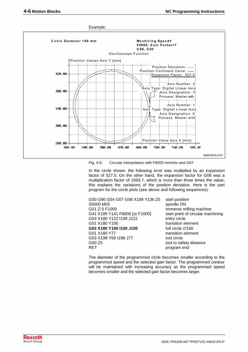
Fig. 4-6: Circular interpolation with F8000 mm/min and G07
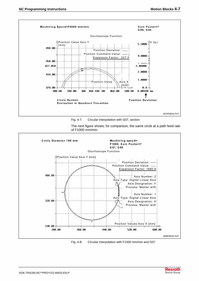
In the circle shown, the following error was multiplied by an expansionfactor of 527.5. On the other hand, the expansion factor for G06 was amultiplication factor of 1693.7, which is more than three times the value;this explains the variations of the position deviation. Here is the partprogram for the circle plots (see above and following sequences):
G00 G90 G54 G07 G08 X199 Y136 Z5 start positionS5000 M03 spindle ONG01 Z-5 F1000 immerse milling machineG41 X199 Y141 F8000 [or F1000] start point of circular machiningG03 X180 Y122 I199 J122 entry circleG01 X180 Y100 transition elementG02 X180 Y100 I100 J100 full circle ∅160G01 X180 Y77 transition elementG03 X198 Y59 I198 J77 exit circleG00 Z5 tool to safety distanceRET program end
The diameter of the programmed circle becomes smaller according to theprogrammed speed and the selected gain factor. The programmed contourwill be maintained with increasing accuracy as the programmed speedbecomes smaller and the selected gain factor becomes larger.
NC Programming Instructions Motion Blocks 4-7
DOK-TRA200-NC**PRO*V22-AW02-EN-P
���� � ���������� ���
���� �������� ����
���� ��������������������������� ��� -,��-
� � � � �� � !"��� �#� � � ��
���� ��������
�� ��� � ���� ��������%%,%�
����
��������
� !&� �! �$ '�� �!� �"�� � � � �!('� � )� �! � � �*)� �"� � +"� &� �!
!���%
���� ��������!��� "��#
"��#
407KREIS.FH7
Fig. 4-7: Circular interpolation with G07, section
The next figure shows, for comparison, the same circle at a path feed rateof F1000 mm/min.
���� � ���������� ���
���� �������� ���� ���� ����������������
����������� ��� ��01��
���� ��������!��� "��#
�� ��� � �� &� �������� � � � � � �� � !"��� ��� � � ��
���� ���������!���%"��#
� �"�� �$�� % " � � #��%%
����
�������
�
!�������$�� ���� %��������&�� ��.� /
!���'��(��� � !���)*�����$� � � + �����!���
!�������$�� ���� ��������&�� ��.� /
!���)*�����$� � � + �����!���!���'��(��� ,
408KREIS.FH7
Fig. 4-8: Circular interpolation with F1000 mm/min and G07
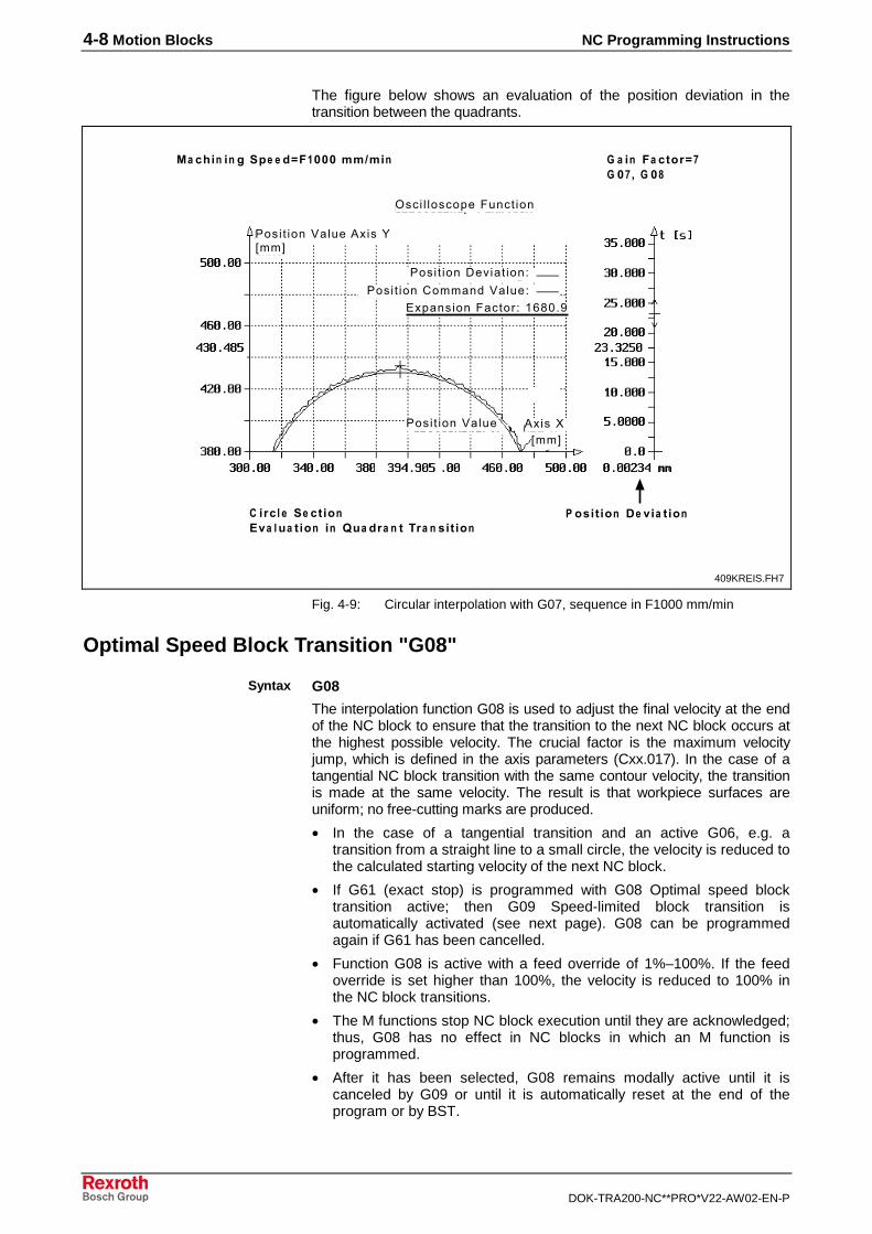
4-8 Motion Blocks NC Programming Instructions
DOK-TRA200-NC**PRO*V22-AW02-EN-P
The figure below shows an evaluation of the position deviation in thetransition between the quadrants.
���� � ���������� ���
���� �������� ����
���� ��������������������������� ��� ��01��
� � � � �� � !"��� ��� � � ��
���� ��������
�� ��� � ���� ��������%%,%�����
��������
� !&� �! �$ '�� �!� �"�� � � � �!('� � )� �! � � �*)� �"� � +"� &� �!
!���%
���� ��������!��� "��#
"��#
409KREIS.FH7
Fig. 4-9: Circular interpolation with G07, sequence in F1000 mm/min
Optimal Speed Block Transition "G08"
G08
The interpolation function G08 is used to adjust the final velocity at the endof the NC block to ensure that the transition to the next NC block occurs atthe highest possible velocity. The crucial factor is the maximum velocityjump, which is defined in the axis parameters (Cxx.017). In the case of atangential NC block transition with the same contour velocity, the transitionis made at the same velocity. The result is that workpiece surfaces areuniform; no free-cutting marks are produced.
• In the case of a tangential transition and an active G06, e.g. atransition from a straight line to a small circle, the velocity is reduced tothe calculated starting velocity of the next NC block.
• If G61 (exact stop) is programmed with G08 Optimal speed blocktransition active; then G09 Speed-limited block transition isautomatically activated (see next page). G08 can be programmedagain if G61 has been cancelled.
• Function G08 is active with a feed override of 1%–100%. If the feedoverride is set higher than 100%, the velocity is reduced to 100% inthe NC block transitions.
• The M functions stop NC block execution until they are acknowledged;thus, G08 has no effect in NC blocks in which an M function isprogrammed.
• After it has been selected, G08 remains modally active until it iscanceled by G09 or until it is automatically reset at the end of theprogram or by BST.
Syntax
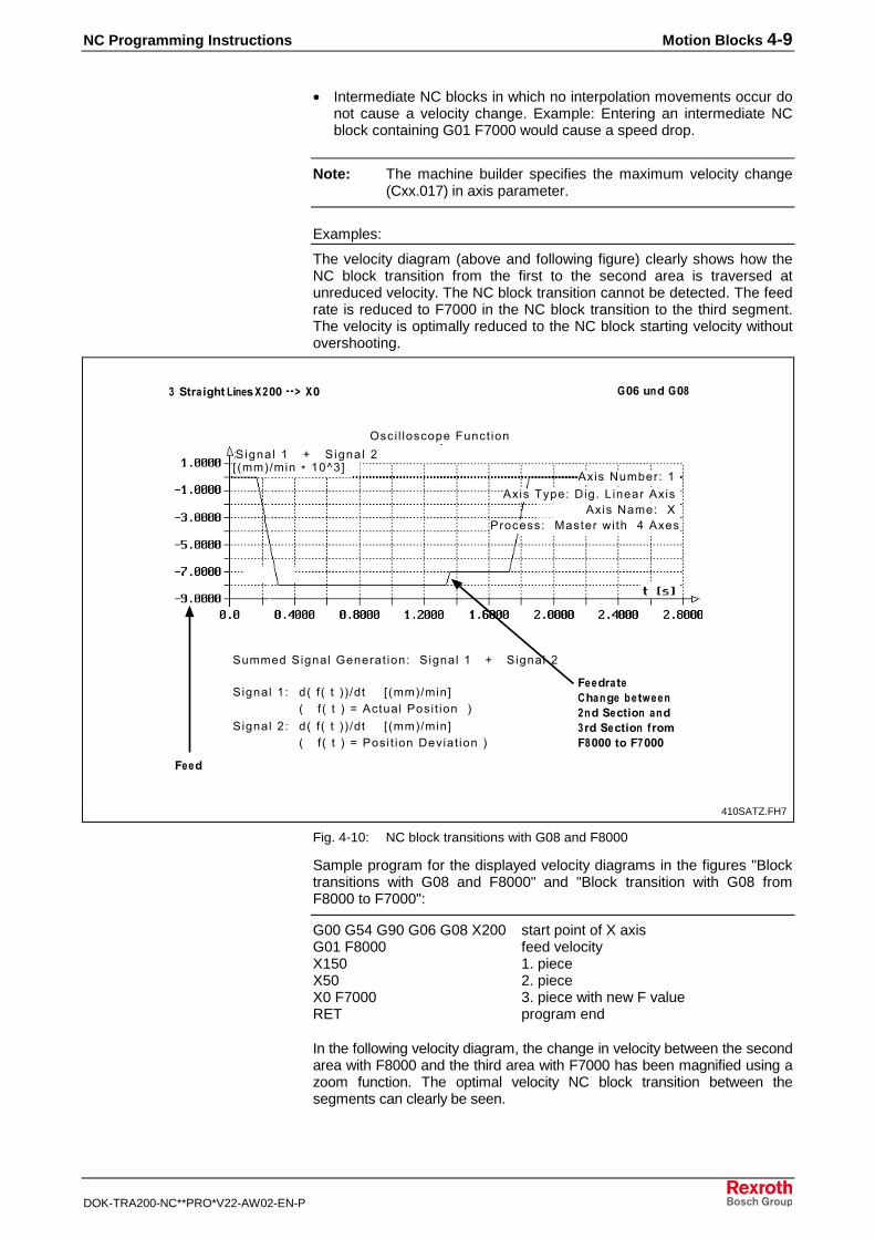
NC Programming Instructions Motion Blocks 4-9
DOK-TRA200-NC**PRO*V22-AW02-EN-P
• Intermediate NC blocks in which no interpolation movements occur donot cause a velocity change. Example: Entering an intermediate NCblock containing G01 F7000 would cause a speed drop.
Note: The machine builder specifies the maximum velocity change(Cxx.017) in axis parameter.
Examples:
The velocity diagram (above and following figure) clearly shows how theNC block transition from the first to the second area is traversed atunreduced velocity. The NC block transition cannot be detected. The feedrate is reduced to F7000 in the NC block transition to the third segment.The velocity is optimally reduced to the NC block starting velocity withoutovershooting.
���� � ���������� ���
!���'��(��� �
��#�)�����
2�����2�$��� 3����� ���� 2�$��� � 4 2�$��� ,
-�� "���� �.�&��/��� 0 01 ���
����
��������
��"� �����2 3/���� �!���-"���� �!� 4"!%������ !������
2�$��� �� �5 6 5 7 7 8� " 5��78���#5 6 5 7 9!� ��� ���� ��� 7
2�$��� ,� �5 6 5 7 7 8� " 5��78���#5 6 5 7 9���� �������� ���7
2 �$�� � � 4 2 �$�� � ,
!���)*�����$� + �����!��� !���'���� %
�������� &�� ��.� / :!���
��
" 5��78���; �1<�#
410SATZ.FH7
Fig. 4-10: NC block transitions with G08 and F8000
Sample program for the displayed velocity diagrams in the figures "Blocktransitions with G08 and F8000" and "Block transition with G08 fromF8000 to F7000":
G00 G54 G90 G06 G08 X200 start point of X axisG01 F8000 feed velocityX150 1. pieceX50 2. pieceX0 F7000 3. piece with new F valueRET program end
In the following velocity diagram, the change in velocity between the secondarea with F8000 and the third area with F7000 has been magnified using azoom function. The optimal velocity NC block transition between thesegments can clearly be seen.
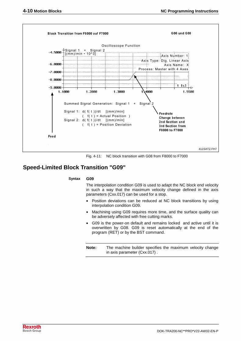
4-10 Motion Blocks NC Programming Instructions
DOK-TRA200-NC**PRO*V22-AW02-EN-P
���� � ���������� ���
!���'��(��� �
��#�)�������!�5�+"�&� �!� 4"!%��������)4 ������
����
��������
��"� �����2 3/���� �!���-"���� �!� 4"!%������ !������
2�$�� � � 4 2 �$�� � ,
!���)*�����$� + �����!��� !���'���� %
��������&�� ��.� /:!���
��
2�����2�$��� 3����� ���� 2�$��� � 4 2�$��� ,
2�$��� �� �5 6 5 7 7 8� " 5��78���#5 6 5 7 9!� ��� ���� ��� 7
2�$��� ,� �5 6 5 7 7 8� " 5��78���#5 6 5 7 9���� �������� ���
"5��78���; �1<�#
411SATZ.FH7
Fig. 4-11: NC block transition with G08 from F8000 to F7000
Speed-Limited Block Transition "G09"
G09
The interpolation condition G09 is used to adapt the NC block end velocityin such a way that the maximum velocity change defined in the axisparameters (Cxx.017) can be used for a stop.
• Position deviations can be reduced at NC block transitions by usinginterpolation condition G09.
• Machining using G09 requires more time, and the surface quality canbe adversely affected with free cutting marks.
• G09 is the power-on default and remains locked and active until it isoverwritten by G08. G09 is reset automatically at the end of theprogram (RET) or by the BST command.
Note: The machine builder specifies the maximum velocity changein axis parameter (Cxx.017) .
Syntax
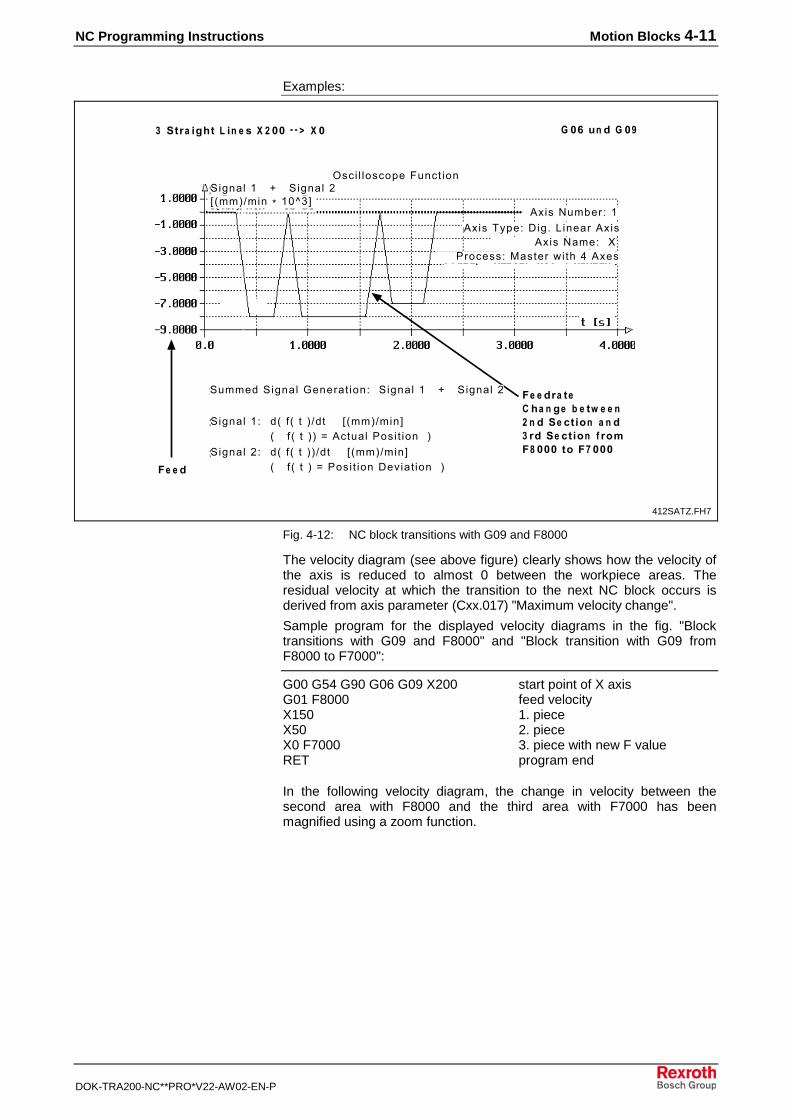
NC Programming Instructions Motion Blocks 4-11
DOK-TRA200-NC**PRO*V22-AW02-EN-P
Examples:
���� � ���������� ���
� �#�) ��� ��- �� "� ��� � . � &� � / ��� 0 0 1 � � ���
���������
�
� �"� � �� � � 2 3 / ��� � �! � � �- "��� � �! � 4 "!%�� ���� !� �� ���
2�$��� � 4 2�$��� ,
!���'��(��� �!���)*�����$� + �����!���
!���'���� % ��������&�� ��.� /:!���
2�����2�$��� 3����� ���� 2�$��� � 4 2�$��� ,
2�$��� �� �5 6 5 7 8� " 5��78���#5 6 5 7 7 9!� ��� ���� ��� 7
2�$��� ,� �5 6 5 7 7 8� " 5��78���#5 6 5 7 9���� �������� ��� 7� �
" 5��78���; �1<�#
412SATZ.FH7
Fig. 4-12: NC block transitions with G09 and F8000
The velocity diagram (see above figure) clearly shows how the velocity ofthe axis is reduced to almost 0 between the workpiece areas. Theresidual velocity at which the transition to the next NC block occurs isderived from axis parameter (Cxx.017) "Maximum velocity change".
Sample program for the displayed velocity diagrams in the fig. "Blocktransitions with G09 and F8000" and "Block transition with G09 fromF8000 to F7000":
G00 G54 G90 G06 G09 X200 start point of X axisG01 F8000 feed velocityX150 1. pieceX50 2. pieceX0 F7000 3. piece with new F valueRET program end
In the following velocity diagram, the change in velocity between thesecond area with F8000 and the third area with F7000 has beenmagnified using a zoom function.
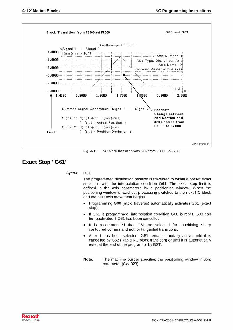
4-12 Motion Blocks NC Programming Instructions
DOK-TRA200-NC**PRO*V22-AW02-EN-P
���� � ���������� ���
� �#�) ��� ��� �!�5 �+"� &� �! � 4 "!%��������)4������
����
�������
�
� �"� � �� � � 2 3 / ��� � �! � � �- "��� � �! � 4 "!%�� ���� !� �� ���
2�$��� � 4 2�$��� ,
!���'��(��� �!���)*�����$� + �����!���
!���'���� %��������&�� ��.� /:!���
2�����2�$��� 3����� ���� 2�$��� � 4 2�$��� ,
2�$��� �� �5 6 5 7 7 8� " 5��78���#5 6 5 7 9!� ��� ���� ��� 7
2�$��� ,� �5 6 5 7 7 8� " 5��78���#5 6 5 7 9���� �������� ��� 7� �
" 5��78���; �1<�#
413SATZ.FH7
Fig. 4-13: NC block transition with G09 from F8000 to F7000
Exact Stop "G61"
G61
The programmed destination position is traversed to within a preset exactstop limit with the interpolation condition G61. The exact stop limit isdefined in the axis parameters by a positioning window. When thepositioning window is reached, processing switches to the next NC blockand the next axis movement begins.
• Programming G00 (rapid traverse) automatically activates G61 (exactstop).
• If G61 is programmed, interpolation condition G08 is reset. G08 canbe reactivated if G61 has been cancelled.
• It is recommended that G61 be selected for machining sharpcontoured corners and not for tangential transitions.
• After it has been selected, G61 remains modally active until it iscancelled by G62 (Rapid NC block transition) or until it is automaticallyreset at the end of the program or by BST.
Note: The machine builder specifies the positioning window in axisparameter (Cxx.023).
Syntax
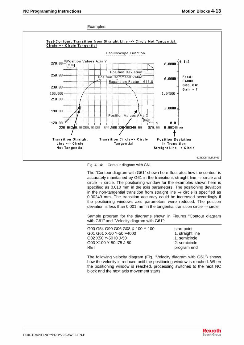
NC Programming Instructions Motion Blocks 4-13
DOK-TRA200-NC**PRO*V22-AW02-EN-P
Examples:
+ & 0 � ! !)"6 � +"� &� �! � 4 "!%�� "� ��� � . � � 0 0 1 � � �"�� �7! � +� � �� � �� �"�� � 0 0 1 � � �"�� � +� � �� �
����
�������
�
���� � ���������� ���
���� �������� ����
���� ��������������������������� ��� ����0
� !&� �! �$ '�� �!� � +"� &� �!
� "� ��� �. � � 0 0 1 �� �"��
+"� &� �! �� "� ��� . � � 0 0 1 � � �"�� 7! � +� � �� �
+"� &� �! � � �"�� 0 0 1 � � �"�� +� � �� �
� �6�8���� �#� � � #�� � � � �� �
���� ���������!��� "��#
���� ���������!���%"��#
414KONTUR.FH7
Fig. 4-14: Contour diagram with G61
The "Contour diagram with G61" shown here illustrates how the contour isaccurately maintained by G61 in the transitions straight line → circle andcircle → circle. The positioning window for the examples shown here isspecified as 0.010 mm in the axis parameters. The positioning deviationin the non-tangential transition from straight line → circle is specified as0.00249 mm. The transition accuracy could be increased accordingly ifthe positioning windows axis parameters were reduced. The positiondeviation is less than 0.001 mm in the tangential transition circle → circle.
Sample program for the diagrams shown in Figures "Contour diagramwith G61" and "Velocity diagram with G61":
G00 G54 G90 G06 G08 X-100 Y-100 start pointG01 G61 X-50 Y-50 F4000 1. straight lineG02 X50 Y-50 I0 J-50 1. semicircleG03 X100 Y-50 I75 J-50 2. semicircleRET program end
The following velocity diagram (Fig. "Velocity diagram with G61") showshow the velocity is reduced until the positioning window is reached. Whenthe positioning window is reached, processing switches to the next NCblock and the next axis movement starts.
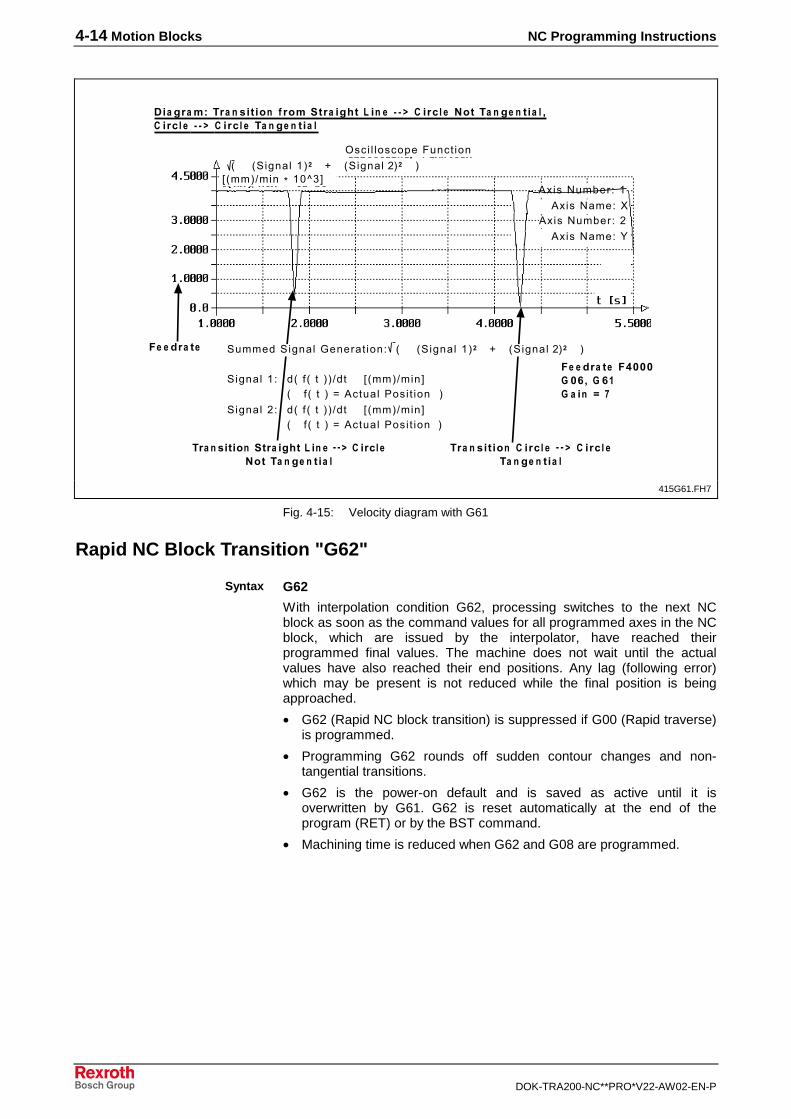
4-14 Motion Blocks NC Programming Instructions
DOK-TRA200-NC**PRO*V22-AW02-EN-P
���� � ���������� ���
$�� �"� %6� +"� &� �! � 4 "!%�� "� ��� � . � � 0 0 1 � � �"�� �7! � +� � �� � �� �"�� � 0 0 1 � � �"�� � +� � �� �
����
�������
�
� �"� � �8���� �#� � � #�� � � � �� �
5 52�$��� �7� 4 52�$��� ,7��� � � �7
!���'��(��� � !���'����%
� �"�
!���'��(��� , !���'����
2�$��� �� �5 6 5 7 7 8� " 5��78���#5 6 5 7 9!� ��� ���� ��� 7
2�$��� ,� �5 6 5 7 7 8� " 5��78���#5 6 5 7 9!� ��� ���� ��� 7
+"� &� �! �� "� ��� �. � � 0 0 1 �� �"�� 7! � +� � �� �
+"� &� �! � � �"�� � 0 0 1 � � �"�� +� � �� �
" 5��78���; �1<�#
2�����2�$��� 3����� ���� 5 52�$��� �7� 4 52�$��� ,7��� � � �7
415G61.FH7
Fig. 4-15: Velocity diagram with G61
Rapid NC Block Transition "G62"
G62
With interpolation condition G62, processing switches to the next NCblock as soon as the command values for all programmed axes in the NCblock, which are issued by the interpolator, have reached theirprogrammed final values. The machine does not wait until the actualvalues have also reached their end positions. Any lag (following error)which may be present is not reduced while the final position is beingapproached.
• G62 (Rapid NC block transition) is suppressed if G00 (Rapid traverse)is programmed.
• Programming G62 rounds off sudden contour changes and non-tangential transitions.
• G62 is the power-on default and is saved as active until it isoverwritten by G61. G62 is reset automatically at the end of theprogram (RET) or by the BST command.
• Machining time is reduced when G62 and G08 are programmed.
Syntax
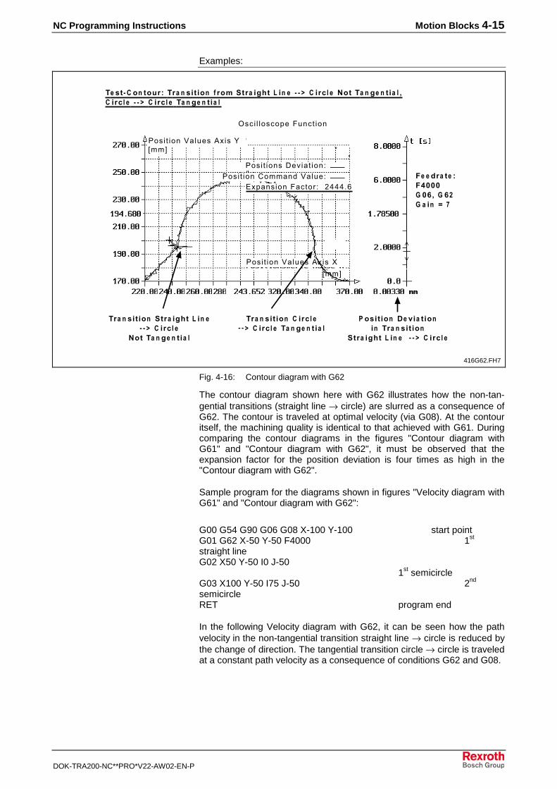
NC Programming Instructions Motion Blocks 4-15
DOK-TRA200-NC**PRO*V22-AW02-EN-P
Examples:
���� ���������!���%
+ & 0 � ! !)"6 � +"� &� �! � 4 "!%�� "� ��� � . � � 0 0 1 � � �"�� �7! � +� � �� � �� �"�� � 0 0 1 � � �"�� � +� � �� �
����
�������
�
���� � ���������� ���
���� ��������� ���� ���� ����������������
����������� ��� ,:::��
���� ���������!���
� !&� �! �$ '�� �!� � +"� &� �!
� "� ��� � . � � � 0 0 1 � � �"��
+"� &� �! �� "� ��� � . � 0 0 1 � � �"��
7! � +� � �� �
+"� &� �! � � �"�� 0 0 1 � � �"�� � +� � �� �
� �"� 6�8���� �#� � � #/� � � � �� �
"��#
"��#
416G62.FH7
Fig. 4-16: Contour diagram with G62
The contour diagram shown here with G62 illustrates how the non-tan-gential transitions (straight line → circle) are slurred as a consequence ofG62. The contour is traveled at optimal velocity (via G08). At the contouritself, the machining quality is identical to that achieved with G61. Duringcomparing the contour diagrams in the figures "Contour diagram withG61" and "Contour diagram with G62", it must be observed that theexpansion factor for the position deviation is four times as high in the"Contour diagram with G62".
Sample program for the diagrams shown in figures "Velocity diagram withG61" and "Contour diagram with G62":
G00 G54 G90 G06 G08 X-100 Y-100 start pointG01 G62 X-50 Y-50 F4000 1st
straight lineG02 X50 Y-50 I0 J-50
1st semicircle
G03 X100 Y-50 I75 J-50 2nd
semicircleRET program end
In the following Velocity diagram with G62, it can be seen how the pathvelocity in the non-tangential transition straight line → circle is reduced bythe change of direction. The tangential transition circle → circle is traveledat a constant path velocity as a consequence of conditions G62 and G08.
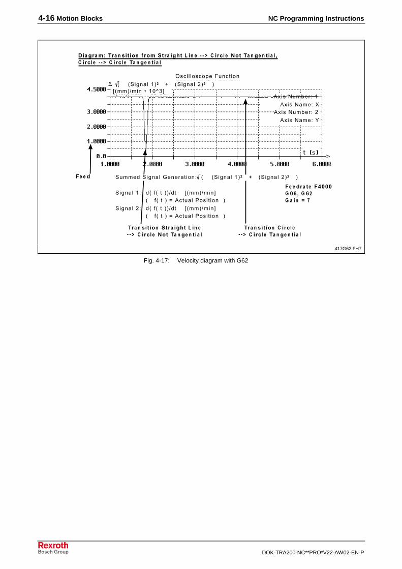
4-16 Motion Blocks NC Programming Instructions
DOK-TRA200-NC**PRO*V22-AW02-EN-P
���� � ���������� ���
$�� �"� %6� +"� &� �! � 4 "!%�� "� ��� � . � � 0 0 1 � � �"�� �7! � +� � �� � �� �"�� � 0 0 1 � � �"�� � +� � �� �
����
�������
�
� �"� � �8���� �#� � � #/� � � � �� �
5 52�$��� �7� 4 52�$��� ,7��� � � �7
!���'��(��� � !���'����%
� �
!���'��(��� , !���'����
2�$��� �� �5 6 5 7 7 8� " 5��78���#5 6 5 7 9!� ��� ���� ��� 7
2�$��� ,� �5 6 5 7 7 8� " 5��78���#5 6 5 7 9!� ��� ���� ��� 7
+"� &� �! �� "� ��� � . � 0 0 1 � � �"�� �7! � +� � �� �
+"� &� �! � � �"�� 0 0 1 � � �"�� � +� � �� �
" 5��78���; �1<�#
2�����2�$��� 3����� ���� 5 52�$��� �7� 4 52�$��� ,7��� � � �7
417G62.FH7
Fig. 4-17: Velocity diagram with G62
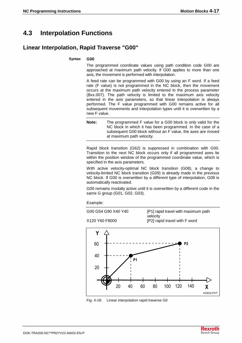
NC Programming Instructions Motion Blocks 4-17
DOK-TRA200-NC**PRO*V22-AW02-EN-P
4.3 Interpolation Functions
Linear Interpolation, Rapid Traverse "G00"
G00
The programmed coordinate values using path condition code G00 areapproached at maximum path velocity. If G00 applies to more than oneaxis, the movement is performed with interpolation.
A feed rate can be programmed with G00 by using an F word. If a feedrate (F value) is not programmed in the NC block, then the movementoccurs at the maximum path velocity entered in the process parameter(Bxx.007). The path velocity is limited to the maximum axis velocityentered in the axis parameters, so that linear interpolation is alwaysperformed. The F value programmed with G00 remains active for allsubsequent movements and interpolation types until it is overwritten by anew F value.
Note: The programmed F value for a G00 block is only valid for theNC block in which it has been programmed. In the case of asubsequent G00 block without an F value, the axes are movedat maximum path velocity.
Rapid block transition (G62) is suppressed in combination with G00.Transition to the next NC block occurs only if all programmed axes liewithin the position window of the programmed coordinate value, which isspecified in the axis parameters.
With active velocity-optimal NC block transition (G08), a change tovelocity-limited NC block transition (G09) is already made in the previousNC block. If G00 is overwritten by a different type of interpolation, G08 isautomatically reactivated.
G00 remains modally active until it is overwritten by a different code in thesame G group (G01, G02, G03).
Example:
G00 G54 G90 X40 Y40 [P1] rapid travel with maximum pathvelocity
X120 Y60 F8000 [P2] rapid travel with F word
��
��
�
�� �� � !� ��� ��� ���
�/
�
��
419G0.FH7
Fig. 4-18: Linear interpolation rapid traverse G0
Syntax
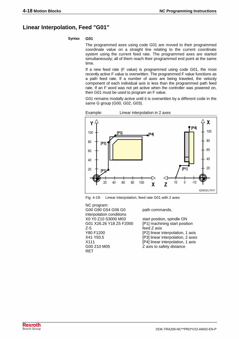
4-18 Motion Blocks NC Programming Instructions
DOK-TRA200-NC**PRO*V22-AW02-EN-P
Linear Interpolation, Feed "G01"
G01
The programmed axes using code G01 are moved to their programmedcoordinate value on a straight line relating to the current coordinatesystem using the current feed rate. The programmed axes are startedsimultaneously; all of them reach their programmed end point at the sametime.
If a new feed rate (F value) is programmed using code G01, the mostrecently active F value is overwritten. The programmed F value functions asa path feed rate. If a number of axes are being traveled, the velocitycomponent of each individual axis is less than the programmed path feedrate. If an F word was not yet active when the controller was powered on,then G01 must be used to program an F value.
G01 remains modally active until it is overwritten by a different code in thesame G group (G00, G02, G03).
Example: Linear interpolation in 2 axes
�
��8���-�
��/�
����
�
�
����
��8�
��
��
�
!�
���
�� �� � !� ��� "�����
��
��
�
!�
���
420G01.FH7
Fig. 4-19: Linear interpolation, feed rate G01 with 2 axes
NC program:G00 G90 G54 G06 G0 path commands, interpolation conditionsX0 Y0 Z10 S3000 M03 start position, spindle ONG01 X26.26 Y18 Z5 F2000 [P1] machining start positionZ-5 feed Z axisY80 F1200 [P2] linear interpolation, 1 axisX41 Y93.5 [P3] linear interpolation, 2 axesX111 [P4] linear interpolation, 1 axisG00 Z10 M05 Z axis to safety distanceRET
Syntax
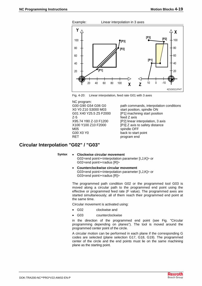
NC Programming Instructions Motion Blocks 4-19
DOK-TRA200-NC**PRO*V22-AW02-EN-P
Example: Linear interpolation in 3 axes
�� �� � !� ��� �
��-�
��/�
����
�
� "�����
����
��-� ��/�
��
��
�
!�
���
��
��
�
!�
���
421G013.FH7
Fig. 4-20: Linear interpolation, feed rate G01 with 3 axes
NC program:G00 G90 G54 G06 G0 path commands, interpolation conditionsX0 Y0 Z10 S3000 M03 start position, spindle ONG01 X40 Y25.5 Z5 F2000 [P1] machining start positionZ-5 feed Z axisX95.74 Y80 Z-10 F1200 [P2] linear interpolation, 3 axisX100 Y100 Z10 F2000 [P3] Z axis to safety distanceM05 spindle OFFG00 X0 Y0 back to start pointRET program end
Circular Interpolation "G02" / "G03"
• Clockwise circular movementG02<end point><interpolation parameter [I,J,K]> orG02<end point><radius [R]>
• Counterclockwise circular movementG03<end point><interpolation parameter [I,J,K]> orG03<end point><radius [R]>
The programmed path condition G02 or the programmed tool G03 ismoved along a circular path to the programmed end point using theeffective or programmed feed rate (F value). The programmed axes arestarted simultaneously; all of them reach their programmed end point atthe same time.
Circular movement is activated using:
• G02 clockwise and
• G03 counterclockwise
in the direction of the programmed end point (see Fig. "Circularprogramming depending on planes"). The tool is moved around theprogrammed center point of the circle.
A circular motion can be performed in each plane if the corresponding Gcodes are selected (plane selection G17, G18, G19). The programmedcenter of the circle and the end points must lie on the same machiningplane as the starting point.
Syntax
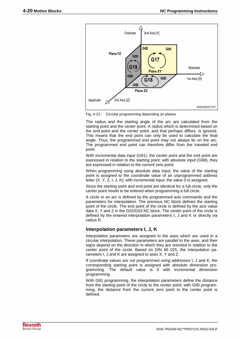
4-20 Motion Blocks NC Programming Instructions
DOK-TRA200-NC**PRO*V22-AW02-EN-P
����������
�� ��������
�� ��������
��������
�� �����
���������
������
���� �
���
����� ���
���
��-
��/
��-��/
��-
��/
422KREIS.FH7
Fig. 4-21: Circular programming depending on planes
The radius and the starting angle of the arc are calculated from thestarting point and the center point. A radius which is determined based onthe end point and the center point, and that perhaps differs, is ignored.This means that the end point can only be used to calculate the finalangle. Thus, the programmed end point may not always lie on the arc.The programmed end point can therefore differ from the traveled endpoint.
With incremental data input (G91), the center point and the end point areexpressed in relation to the starting point; with absolute input (G90), theyare expressed in relation to the current zero point.
When programming using absolute data input, the value of the startingpoint is assigned to the coordinate value of an unprogrammed addressletter (X, Y, Z, I, J, K); with incremental input, the value 0 is assigned.
Since the starting point and end point are identical for a full circle, only thecenter point needs to be entered when programming a full circle.
A circle or an arc is defined by the programmed axis commands and theparameters for interpolation. The previous NC block defines the startingpoint of the circle. The end point of the circle is defined by the axis valuedata X, Y and Z in the G02/G03 NC block. The center point of the circle isdefined by the entered interpolation parameters I, J and K or directly viaradius R.
Interpolation parameters I, J, KInterpolation parameters are assigned to the axes which are used in acircular interpolation. These parameters are parallel to the axes, and theirsigns depend on the direction in which they are oriented in relation to thecenter point of the circle. Based on DIN 66 025, the interpolation pa-rameters I, J and K are assigned to axes X, Y and Z.
If coordinate values are not programmed using addresses I, J and K, thecorresponding starting point is assigned with absolute dimension pro-gramming. The default value is 0 with incremental dimensionprogramming.
With G91 programming, the interpolation parameters define the distancefrom the starting point of the circle to the center point; with G90 program-ming, the distance from the current zero point to the center point isdefined.

NC Programming Instructions Motion Blocks 4-21
DOK-TRA200-NC**PRO*V22-AW02-EN-P
�
"#�$%&�'
"(�$%&�'
)#�$%&�'
)(�$%&�'
*������+�,-���.� ��-��� /������,-���
423KREIS.FH7
Fig. 4-22: Circular interpolation with interpolation parameters
Example: Full circle in the X-Y plane with G90
��
��
�
!�
���
�� �� � !� ��� ��� ��� �
����
9�#�
:�#�
��
������ "��!�
424VOLL.FH7
Fig. 4-23: Full circle with G90
NC program:G00 G90 G54 G06 G0 path commands, interpolation conditionsX0 Y0 Z10 S3000 M03 start position, spindle ONG01 X40 Y37.24 F2000 circle start pointZ-10 F500 feed Z axisG02 X40 Y37.24 I60 J60 full circle, clockwiseAlternatively: G02 I60 J60 for full circle, without circle end pointG00 Z10 Z axis to safety distanceM05 spindle OFFX0 Y0 back to start pointRET program end
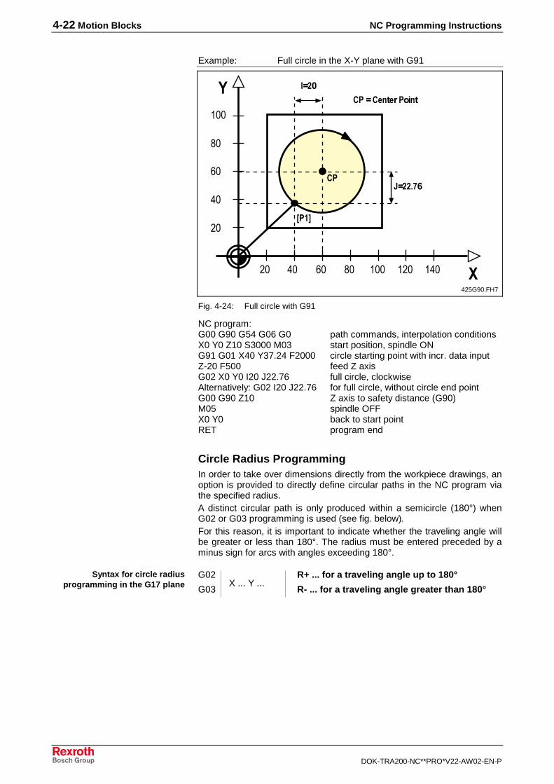
4-22 Motion Blocks NC Programming Instructions
DOK-TRA200-NC**PRO*V22-AW02-EN-P
Example: Full circle in the X-Y plane with G91
��
��
�
!�
���
�� �� � !� ��� ��� ��� �
����
9�/�
��:�//;�#
������ "��!�
425G90.FH7
Fig. 4-24: Full circle with G91
NC program:G00 G90 G54 G06 G0 path commands, interpolation conditionsX0 Y0 Z10 S3000 M03 start position, spindle ONG91 G01 X40 Y37.24 F2000 circle starting point with incr. data inputZ-20 F500 feed Z axisG02 X0 Y0 I20 J22.76 full circle, clockwiseAlternatively: G02 I20 J22.76 for full circle, without circle end pointG00 G90 Z10 Z axis to safety distance (G90)M05 spindle OFFX0 Y0 back to start pointRET program end
Circle Radius ProgrammingIn order to take over dimensions directly from the workpiece drawings, anoption is provided to directly define circular paths in the NC program viathe specified radius.A distinct circular path is only produced within a semicircle (180°) whenG02 or G03 programming is used (see fig. below).For this reason, it is important to indicate whether the traveling angle willbe greater or less than 180°. The radius must be entered preceded by aminus sign for arcs with angles exceeding 180°.
G02 R+ ... for a traveling angle up to 180°
G03 R- ... for a traveling angle greater than 180°
Syntax for circle radiusprogramming in the G17 plane X ... Y ...
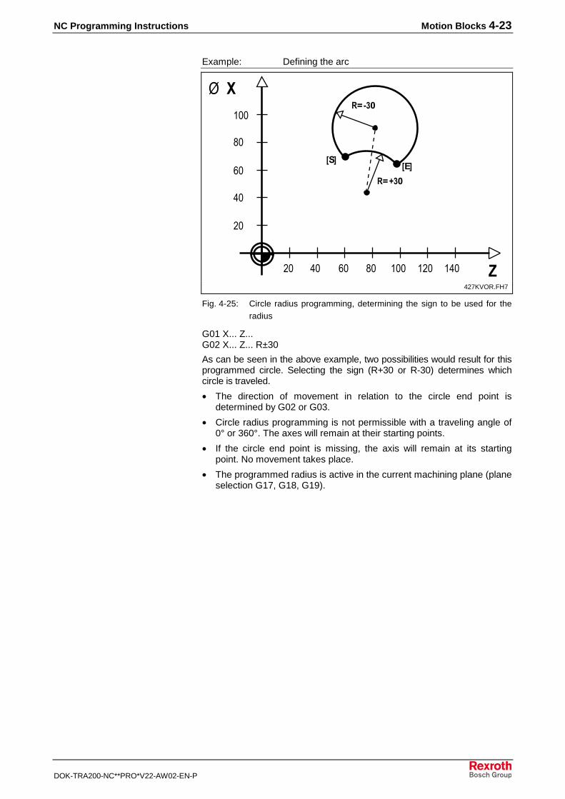
NC Programming Instructions Motion Blocks 4-23
DOK-TRA200-NC**PRO*V22-AW02-EN-P
Example: Defining the arc
��
��
�
!�
���
�
0���
�(�
<��=-�
<��0-�
���
�� �� � !� ��� ��� ���
427KVOR.FH7
Fig. 4-25: Circle radius programming, determining the sign to be used for theradius
G01 X... Z...G02 X... Z... R±30
As can be seen in the above example, two possibilities would result for thisprogrammed circle. Selecting the sign (R+30 or R-30) determines whichcircle is traveled.
• The direction of movement in relation to the circle end point isdetermined by G02 or G03.
• Circle radius programming is not permissible with a traveling angle of0° or 360°. The axes will remain at their starting points.
• If the circle end point is missing, the axis will remain at its startingpoint. No movement takes place.
• The programmed radius is active in the current machining plane (planeselection G17, G18, G19).
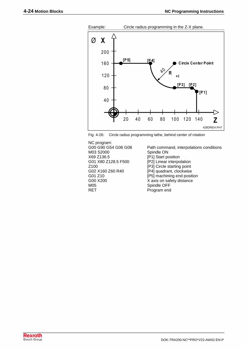
4-24 Motion Blocks NC Programming Instructions
DOK-TRA200-NC**PRO*V22-AW02-EN-P
Example: Circle radius programming in the Z-X plane.
��
!�
���
���
�� �� � !� ��� ��� ��� �
0 ���
��"���� "��!�
��/���-�
��8���>�
= 9<
����
� �
��
428DREH.FH7
Fig. 4-26: Circle radius programming lathe, behind center of rotation
NC program:G00 G90 G54 G06 G08 Path command, interpolations conditionsM03 S2000 Spindle ONX69 Z136.5 [P1] Start positionG01 X80 Z128.5 F500 [P2] Linear interpolationZ100 [P3] Circle starting pointG02 X160 Z60 R40 [P4] quadrant, clockwiseG01 Z10 [P5] machining end positionG00 X200 X axis on safety distanceM05 Spindle OFFRET Program end
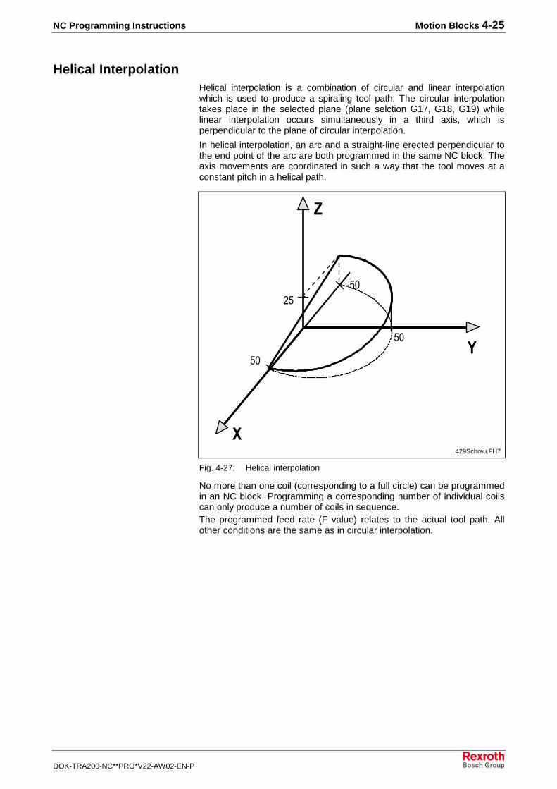
NC Programming Instructions Motion Blocks 4-25
DOK-TRA200-NC**PRO*V22-AW02-EN-P
Helical InterpolationHelical interpolation is a combination of circular and linear interpolationwhich is used to produce a spiraling tool path. The circular interpolationtakes place in the selected plane (plane selction G17, G18, G19) whilelinear interpolation occurs simultaneously in a third axis, which isperpendicular to the plane of circular interpolation.
In helical interpolation, an arc and a straight-line erected perpendicular tothe end point of the arc are both programmed in the same NC block. Theaxis movements are coordinated in such a way that the tool moves at aconstant pitch in a helical path.
�1
1�
1�
"1�
�
�429Schrau.FH7
Fig. 4-27: Helical interpolation
No more than one coil (corresponding to a full circle) can be programmedin an NC block. Programming a corresponding number of individual coilscan only produce a number of coils in sequence.The programmed feed rate (F value) relates to the actual tool path. Allother conditions are the same as in circular interpolation.
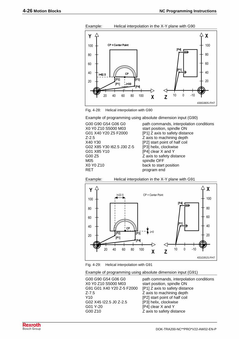
4-26 Motion Blocks NC Programming Instructions
DOK-TRA200-NC**PRO*V22-AW02-EN-P
Example: Helical interpolation in the X-Y plane with G90
�� �� � !� ��� �
�
� "�����
����
��/� ��-�
��8�
����
��8�
��9�#/;>
:�-���
��
�
!�
���
��
��
�
!�
��������� "��!�
430G90S.FH7
Fig. 4-28: Helical interpolation with G90
Example of programming using absolute dimension input (G90)
G00 G90 G54 G06 G0 path commands, interpolation conditionsX0 Y0 Z10 S5000 M03 start position, spindle ONG01 X40 Y20 Z5 F2000 [P1] Z axis to safety distanceZ-2.5 Z axis to machining depthX40 Y30 [P2] start point of half coilG02 X85 Y30 I62.5 J30 Z-5 [P3] helix, clockwiseG01 X85 Y10 [P4] clear X and YG00 Z5 Z axis to safety distanceM05 spindle OFFX0 Y0 Z10 back to start positionRET program end
Example: Helical interpolation in the X-Y plane with G91
��
��
�
!�
���
�� �� � !� ��� �
��
��
�
!�
���
�
� "�����
����
��/� ��-�
��8�
����
��8�
��#2�
(2���1 /,�2�/������,-���
431G91S.FH7
Fig. 4-29: Helical interpolation with G91
Example of programming using absolute dimension input (G91)
G00 G90 G54 G06 G0 path commands, interpolation conditionsX0 Y0 Z10 S5000 M03 start position, spindle ONG91 G01 X40 Y20 Z-5 F2000 [P1] Z axis to safety distanceZ-7.5 Z axis to machining depthY10 [P2] start point of half coilG02 X45 I22.5 J0 Z-2.5 [P3] helix, clockwiseG01 Y-20 [P4] clear X and YG00 Z10 Z axis to safety distance

NC Programming Instructions Motion Blocks 4-27
DOK-TRA200-NC**PRO*V22-AW02-EN-P
M05 spindle OFFX-85 Y-10 Z5 back to start positionRET program end
Tapping "G63" / "G64"With function G63, threads can be tapped without a compensating chuck. Inthread tapping without a compensating chuck, not only is the spindle speedcontrolled (as would be the case in normal tapping), but also the spindlealignment. The spindle rotation and the feed movement of the axis, which isprogrammed together with G63, are linearly interpolated. A main spindle,which can be positioned, is required for tapping without a compensatingchuck. The spindle must be driven directly (slip); the position encodershould be located directly on the spindle.
The CNC supplies two preparatory functions for tapping without acompensating chuck. These functions are only active for the duration ofthe NC block containing them.
• G63 - Spindle stops at the end of movement
• G64 - Spindle continues rotating after the end of motion
The functions G63 and G64 differ only with respect to the end of motion.
G63 <end point [X,Y,Z]> <feed per spindle revolution [F]>
G64 <end point [X,Y,Z]> <feed per spindle revolution [F]>
Two cases are possible when the feed/spindle link is established:
• The spindle is not turning (n=0)
• The spindle is already turning (n=S)
If the spindle is not turning when the feed/spindle link is established, thelink can be activated at the start of the common acceleration phase sothat the spindle and the feed axis are already accelerating in aninterpolating way. The selected acceleration focuses on the weakest axis(main spindle or feed axis).
If the spindle is already rotating when the feed/spindle link is established,the feed axis accelerates to the required speed at its maximumacceleration, and then the link is activated, so that the main spindle andthe feed axis do not interpolate until the constant-speed range is reached.
• Clockwise or counterclockwise thread tapping is achieved by declaringthe direction of rotation of the spindle: M03 or M04.
• If a different spindle is to be selected for thread tapping using G63/64,the spindle must be activated by means of the SPF <spindle number>command prior to NC block G63. The first spindle is always active inthe power-on state.
• Tapping should be performed using function G06 ‘Positioning withoutlag’. If G06 is not active with tapping without a compensating chuck orif analog axis cards are installed, the same gain factor must be set forthe spindle and for the feed axis for G63/G64.
• The functions G08 (Velocity-optimal NC block transition) and G61(Exact stop) are meaningless for tapping.
• A main spindle which is stopped at the end of the movement (G63)can be reactivated using the spindle control commands M03/M04 andby programming the speed value (S value).
• If the tap is turned out of the thread using G64, the spindle stopsbriefly at the end point of the NC block in order to change fromposition-controlled to speed-controlled mode.
Syntax
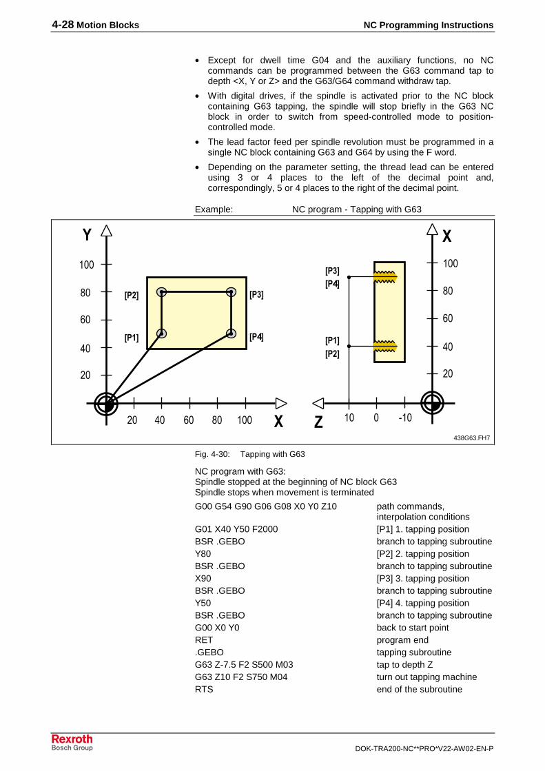
4-28 Motion Blocks NC Programming Instructions
DOK-TRA200-NC**PRO*V22-AW02-EN-P
• Except for dwell time G04 and the auxiliary functions, no NCcommands can be programmed between the G63 command tap todepth <X, Y or Z> and the G63/G64 command withdraw tap.
• With digital drives, if the spindle is activated prior to the NC blockcontaining G63 tapping, the spindle will stop briefly in the G63 NCblock in order to switch from speed-controlled mode to position-controlled mode.
• The lead factor feed per spindle revolution must be programmed in asingle NC block containing G63 and G64 by using the F word.
• Depending on the parameter setting, the thread lead can be enteredusing 3 or 4 places to the left of the decimal point and,correspondingly, 5 or 4 places to the right of the decimal point.
Example: NC program - Tapping with G63
��
��
�
!�
���
�� �� � !� ��� �
��
��
�
!�
���
�
� "�����
��/�
����
��-�
��8� ������/�
��-���8�
438G63.FH7
Fig. 4-30: Tapping with G63
NC program with G63:Spindle stopped at the beginning of NC block G63Spindle stops when movement is terminated
G00 G54 G90 G06 G08 X0 Y0 Z10 path commands,interpolation conditions
G01 X40 Y50 F2000 [P1] 1. tapping positionBSR .GEBO branch to tapping subroutineY80 [P2] 2. tapping positionBSR .GEBO branch to tapping subroutineX90 [P3] 3. tapping positionBSR .GEBO branch to tapping subroutineY50 [P4] 4. tapping positionBSR .GEBO branch to tapping subroutineG00 X0 Y0 back to start pointRET program end.GEBO tapping subroutineG63 Z-7.5 F2 S500 M03 tap to depth ZG63 Z10 F2 S750 M04 turn out tapping machineRTS end of the subroutine

NC Programming Instructions Motion Blocks 4-29
DOK-TRA200-NC**PRO*V22-AW02-EN-P
Spindle already turning at the beginning of NC block G63Spindle stops when movement is terminated
G00 G54 G90 G06 G08 X0 Y0 Z10 path commands,interpolation conditions
G01 X40 Y50 F2000 M03 S1000 [P1] 1. tapping position,spindle ON
BSR .GEBO branch to tapping subroutineY80 M03 S1000 [P2] 2. tapping position,
spindle ONBSR .GEBO branch to tapping subroutineX90 M03 S1000 [P3] 3. tapping position,
spindle ONBSR .GEBO branch to tapping subroutineY50 M03 S1000 [P4] 4. tapping position,
spindle ONBSR .GEBO branch to tapping subroutineG00 X0 Y0 back to start pointRET program end.GEBO tapping subroutineG63 Z-7.5 F2 tap to depth ZG63 Z10 F2 S750 M04 turn out tapping machineRTS end of the subroutine
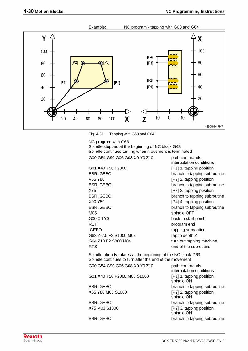
4-30 Motion Blocks NC Programming Instructions
DOK-TRA200-NC**PRO*V22-AW02-EN-P
Example: NC program - tapping with G63 and G64
��
��
�
!�
���
�� �� � !� ��� �
��
��
�
!�
���
�
� "�����
��/�
����
��-�
��8� ��/�
����
��8�
��-�
439G634.FH7
Fig. 4-31: Tapping with G63 and G64
NC program with G63:Spindle stopped at the beginning of NC block G63Spindle continues turning when movement is terminated
G00 G54 G90 G06 G08 X0 Y0 Z10 path commands,interpolation conditions
G01 X40 Y50 F2000 [P1] 1. tapping positionBSR .GEBO branch to tapping subroutineV55 Y80 [P2] 2. tapping positionBSR .GEBO branch to tapping subroutineX75 [P3] 3. tapping positionBSR .GEBO branch to tapping subroutineX90 Y50 [P4] 4. tapping positionBSR .GEBO branch to tapping subroutineM05 spindle OFFG00 X0 Y0 back to start pointRET program end.GEBO tapping subroutineG63 Z-7.5 F2 S1000 M03 tap to depth ZG64 Z10 F2 S800 M04 turn out tapping machineRTS end of the subroutine
Spindle already rotates at the beginning of the NC block G63Spindle continues to turn after the end of the movement
G00 G54 G90 G06 G08 X0 Y0 Z10 path commands,interpolation conditions
G01 X40 Y50 F2000 M03 S1000 [P1] 1. tapping position, spindle ON
BSR .GEBO branch to tapping subroutineX55 Y80 M03 S1000 [P2] 2. tapping position,
spindle ONBSR .GEBO branch to tapping subroutineX75 M03 S1000 [P2] 3. tapping position,
spindle ONBSR .GEBO branch to tapping subroutine
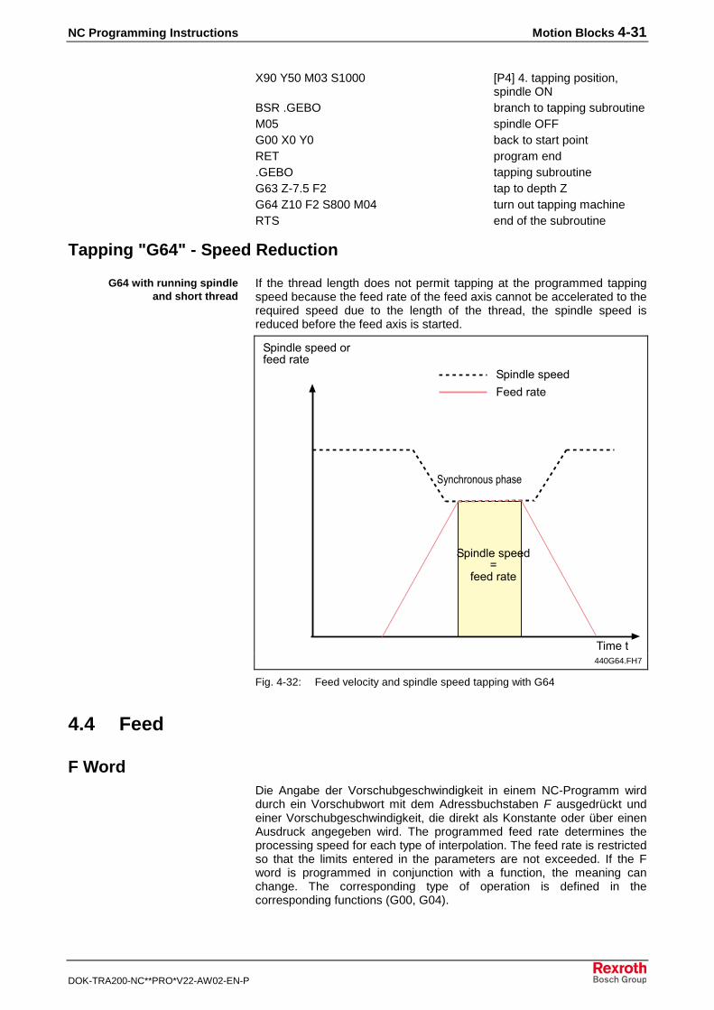
NC Programming Instructions Motion Blocks 4-31
DOK-TRA200-NC**PRO*V22-AW02-EN-P
X90 Y50 M03 S1000 [P4] 4. tapping position,spindle ON
BSR .GEBO branch to tapping subroutineM05 spindle OFFG00 X0 Y0 back to start pointRET program end.GEBO tapping subroutineG63 Z-7.5 F2 tap to depth ZG64 Z10 F2 S800 M04 turn out tapping machineRTS end of the subroutine
Tapping "G64" - Speed Reduction
If the thread length does not permit tapping at the programmed tappingspeed because the feed rate of the feed axis cannot be accelerated to therequired speed due to the length of the thread, the spindle speed isreduced before the feed axis is started.
2�������������6����� �
2�����������9
6����� �
����� �
2�����������
)���
*3����-�-4�������
440G64.FH7
Fig. 4-32: Feed velocity and spindle speed tapping with G64
4.4 Feed
F WordDie Angabe der Vorschubgeschwindigkeit in einem NC-Programm wirddurch ein Vorschubwort mit dem Adressbuchstaben F ausgedrückt undeiner Vorschubgeschwindigkeit, die direkt als Konstante oder über einenAusdruck angegeben wird. The programmed feed rate determines theprocessing speed for each type of interpolation. The feed rate is restrictedso that the limits entered in the parameters are not exceeded. If the Fword is programmed in conjunction with a function, the meaning canchange. The corresponding type of operation is defined in thecorresponding functions (G00, G04).
G64 with running spindleand short thread
4-32 Motion Blocks NC Programming Instructions
DOK-TRA200-NC**PRO*V22-AW02-EN-P
F<constant> � F1000F<expression>� F=@50
If the F word is programmed as the feed rate, it becomes the desiredvalue for the machining speed.
The F word interacts with the associated G code as follows:
Meaning G code Active Format Comments
G63, G64 blockwise 43
45
The F value is reactivated if G63, G64 are renewed.This has no effect on the F values of G94.
Time in seconds G04 blockwise 3 2 Superimposed with F words that were programmedby other G codes.
If the F word appears alone in the NC block, it is assigned to the memory ofthe modally active conditions of the feed specified group. If the F wordappears in an NC block together with one of these functions, thecorresponding feed is activated first, and then the F value is placed in theappropriate memory.• When the CNC is in the power-up state, the units mm/min. or inch/min.
are used for the feed rate (feed rate programming).
• The units mm/spindle rotation or inch/spindle rotation are used for thefeed rate in G63, G64.
• With G04 (dwell time), the time is entered in the F word in seconds.
• The programmed feed rate can be changed via the feed rate overridefrom 0% to 255%. The 100% position corresponds to the programmedvalue.
The feed values are reset after the controller has been powered on, theprogram is loaded into the controller, or after a BST, RET, or Control-Reset (PxxC.CLEAR). At the beginning of an NC program, the feed valuesmust be programmed before or together with the first movement command.
Note: The maximum path and axis speed are defined by themachine builder in the axis parameters (Bxx.005, Cxx.016).
Dwell Time "G04"The function G04 "Dwell time" can be used to program a delay time in theNC program for functions such as relief cutting, machine controlfunctions, etc.
G04 F<time in seconds>
G04 is active on an NC block-by-block basis and must be programmed incombination with an F word. The F word will then correspond to a dwelltime in seconds.
• The maximum directly programmed dwell time is 999.99 seconds(16.7 minutes) and the maximum resolution is 0.01 seconds.
• The F value programmed together with G04 can be programmed withthree digits before and two digits after the decimal point.
• Only the M and S functions can be programmed in a dwell time-programmed NC block.
• The dwell time programmed in the F value using G04 does not affectthe modally active F values (feed rate).
• The F value programmed together with G04 can be programmed with3 digits to the left and 2 digits to the right of the decimal point.
Syntax
Syntax
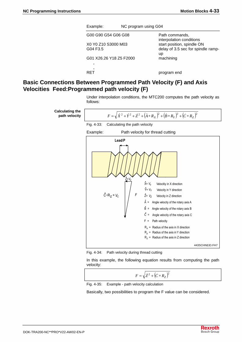
NC Programming Instructions Motion Blocks 4-33
DOK-TRA200-NC**PRO*V22-AW02-EN-P
Example: NC program using G04
G00 G90 G54 G06 G08 Path commands,interpolation conditions
X0 Y0 Z10 S3000 M03 start position, spindle ONG04 F3.5 delay of 3.5 sec for spindle ramp-
upG01 X26.26 Y18 Z5 F2000 machining . .RET program end
Basic Connections Between Programmed Path Velocity (F) and AxisVelocities Feed:Programmed path velocity (F)
Under interpolation conditions, the MTC200 computes the path velocity asfollows:
( ) ( ) ( )222222ZYX RCRBRAZYXF ∗+∗+∗+++= ������
Fig. 4-33: Calculating the path velocity
Example: Path velocity for thread cutting
.����
��� ��256
���22 7��-����3����� ������-�
�2 7��-���3������ ������-�
�2 7��-���3������ ������-�
���2 ��+���8��-���3�-�������-���3�������
9��2 ��+���8��-���3�-�������-���3������9
/��2 ��+���8��-���3�-�������-���3������/
�5 5� �4��-��������������� ������-�2
�5 5� �4��-���������������� ������-�2
�5 5� �4��-���������������� ������-�2
:��2 ,����8��-���3
;;�+<;
��
��
�
443SCHNEID.FH7
Fig. 4-34: Path velocity during thread cutting
In this example, the following equation results from computing the pathvelocity:
( )22ZRCZF ∗+= ��
Fig. 4-35: Example - path velocity calculation
Basically, two possibilities to program the F value can be considered.
Calculating thepath velocity
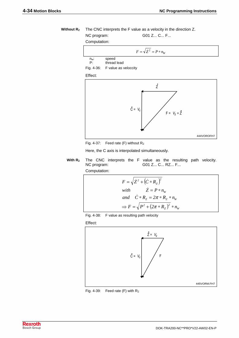
4-34 Motion Blocks NC Programming Instructions
DOK-TRA200-NC**PRO*V22-AW02-EN-P
The CNC interprets the F value as a velocity in the direction Z.
NC program: G01 Z... C... F...
Computation:
WnPZF ∗== 2�
nw: speedP: thread lead
Fig. 4-36: F value as veloccity
Effect:
/�2 �:�2 �� 2��
���
444VOROFH7
Fig. 4-37: Feed rate (F) without RZ
Here, the C axis is interpolated simultaneously.
The CNC interprets the F value as the resulting path velocity.NC program: G01 Z... C... RZ... F...
Computation:
( )
( ) W2
Z2
WZZ
W
2
Z2
nR2PF
nR2RCand
nPZwith
RCZF
∗∗+=�
∗∗=∗∗=
∗+=
π
π�
�
��
Fig. 4-38: F value as resulting path velocity
Effect:
/�2 � :
������2
445VORM.FH7
Fig. 4-39: Feed rate (F) with RZ
Without RZ
With RZ
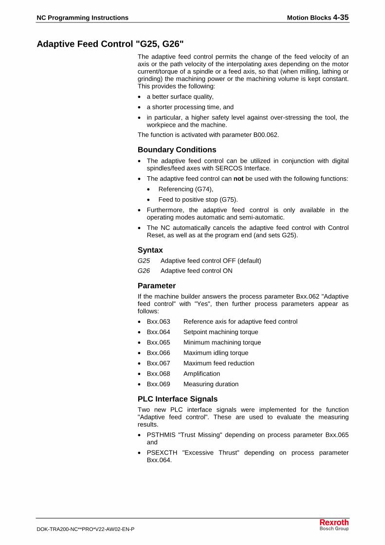
NC Programming Instructions Motion Blocks 4-35
DOK-TRA200-NC**PRO*V22-AW02-EN-P
Adaptive Feed Control "G25, G26"The adaptive feed control permits the change of the feed velocity of anaxis or the path velocity of the interpolating axes depending on the motorcurrent/torque of a spindle or a feed axis, so that (when milling, lathing orgrinding) the machining power or the machining volume is kept constant.This provides the following:
• a better surface quality,
• a shorter processing time, and
• in particular, a higher safety level against over-stressing the tool, theworkpiece and the machine.
The function is activated with parameter B00.062.
Boundary Conditions• The adaptive feed control can be utilized in conjunction with digital
spindles/feed axes with SERCOS Interface.
• The adaptive feed control can not be used with the following functions:
• Referencing (G74),
• Feed to positive stop (G75).
• Furthermore, the adaptive feed control is only available in theoperating modes automatic and semi-automatic.
• The NC automatically cancels the adaptive feed control with ControlReset, as well as at the program end (and sets G25).
SyntaxG25 Adaptive feed control OFF (default)
G26 Adaptive feed control ON
ParameterIf the machine builder answers the process parameter Bxx.062 "Adaptivefeed control" with "Yes", then further process parameters appear asfollows:
• Bxx.063 Reference axis for adaptive feed control
• Bxx.064 Setpoint machining torque
• Bxx.065 Minimum machining torque
• Bxx.066 Maximum idling torque
• Bxx.067 Maximum feed reduction
• Bxx.068 Amplification
• Bxx.069 Measuring duration
PLC Interface SignalsTwo new PLC interface signals were implemented for the function"Adaptive feed control". These are used to evaluate the measuringresults.
• PSTHMIS "Trust Missing" depending on process parameter Bxx.065and
• PSEXCTH "Excessive Thrust" depending on process parameterBxx.064.
4-36 Motion Blocks NC Programming Instructions
DOK-TRA200-NC**PRO*V22-AW02-EN-P
Thrust Missing
Process status signal
PSTHMIS (THrust MISsing)
PSTHMIS = 1:
The machining torque has not exceeded the preselected minimummachining torque Bxx.065 during machining.
PSTHMIS = 0:
The machining torque has exceeded the preselected minimummachining torque Bxx.065 during machining.
The NC updates the interface signal by turning the adaptive feed controlon (G26) and off (G25). The NC resets this signal at the program end aswell as with Control Reset.
If the machining torque does not exceed the adaptive feed controlBxx.065 during machining with the adaptive feed control being active,then the NC reports this as soon as the adaptive feed control is turned offby setting the interface signal ‘Thrust Missing’ (PSTHMIS).
Excessive Thrust
Process status signal
PSEXCTH (EXCessive THrust)
PSEXCTH = 1:
The current feed reduction exceeds the maximum feed reductionBxx.067.
PSEXCTH = 0:
The current feed reduction does not exceed the maximum feed reductionBxx.067.
The NC updates the interface signal by turning the adaptive feed controlon (G26) and off (G25). The NC resets this signal at the program end aswell as with Control Reset.
If the current feed reduction exceeds the maximum feed reductionBxx.067 during machining with adaptive feed control being active, thenthe NC reports this by setting the interface signal ‘Excessive Thrust’(PSEXCTH).
Note: The NC continues machining, independent of whether thecurrent feed reduction exceeds the maximum feed reductionor not. Only if the current feed reduction reaches 100%(meaning the feed velocity = 0 mm/min) and the adjustedmaximum feed reduction Bxx.067 is smaller than 100% doesthe NC stop the machining process and generate errormessage .510 "100%-feed reduction@axis".
Type
Designation
Meaning
Updating
Method of operation
Type
Designation
Meaning
Updating
Method of operation
NC Programming Instructions Motion Blocks 4-37
DOK-TRA200-NC**PRO*V22-AW02-EN-P
Problem of "Inclined Axis"In the case of "inclined axis without counter force", a torque for holdingthe axis in position is required. This holding torque is added as an offsetto all torques that have been recorded so far. This results in a distortion ofthe torques required for the adaptive feed control.
Note: The adaptive feed control is not possible as a reference axis inthe case of an "inclined axis".
The torque offset (standstill torque) required to hold the axis must beeliminated for the adaptive feed control.
A command is required that records the standstill torque.
The standstill torque can be recorded with the commands:
• ITM or
• AXD (APR SERCOS parameter P-7-3651)
The specified reference axis in the parameters is thereby referred to.During adaptive feed control, the standstill torque is considered while thetorque is being generated.
The time specified in the parameters is dwelled and the standstill torque isgenerated.
The parameters APR-SERCOS-Parameter 65091 "Measuring time ofstandstill torque" and 65092 "Standstill torque" have the same unit andrights as "Measuring time of idling torque" and "Idling torque".
Additional DocumentationA detailed description of the function is available under the order number
"Adaptive feed control", DOK-MTC200-AD*FEED*V19-FK01-EN-P.
4.5 Spindle Speed
S Word for the Spindle Speed SpecificationThe spindle speed in an NC program is expressed by a speed word thatuses the address letter S and a speed which is stated directly as aconstant or by means of an expression. A spindle code can also be addedto the speed word if more spindles are present. The spindle speed isrestricted in such a way that the limits entered in the parameters are notexceeded. The S word is interpreted as spindle speed value. Thefollowing chapters describe how the S word interacts in conjunction withthe various spindle functions.
S<constant> � S5000
S<expression> � S=@55-100
with enhanced address format:
S<index> <constant> � S2 3500
S<index> <expression> � S3=@60
The spindle speed value ranges from 0 to the maximum value entered inthe axis parameters Cxx.049 "Maximum spindle speed".
Solution
Syntax
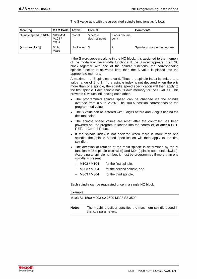
4-38 Motion Blocks NC Programming Instructions
DOK-TRA200-NC**PRO*V22-AW02-EN-P
The S value acts with the associated spindle functions as follows:
Meaning G / M Code Active Format Comments
Spindle speed in RPM M03/M04Mx03 /Mx04
modal 5 beforedecimal point
2 after decimalpoint
(x = index [1 - 3]) M19Mx19
blockwise 3 2 Spindle positioned in degrees
If the S word appears alone in the NC block, it is assigned to the memoryof the modally active spindle functions. If the S word appears in an NCblock together with one of the spindle functions, the correspondingspindle function is activated first; then the S value is placed into theappropriate memory.
A maximum of 3 spindles is valid. Thus, the spindle index is limited to avalue range of 1 to 3. If the spindle index is not declared when there ismore than one spindle, the spindle speed specification will then apply tothe first spindle. Each spindle has its own memory for the S values. Thisprevents S values influencing each other.
• The programmed spindle speed can be changed via the spindleoverride from 0% to 255%. The 100% position corresponds to theprogrammed value.
• The S value can be entered with 5 digits before and 2 digits behind thedecimal point.
• The spindle speed values are reset after the controller has beenpowered on, the program is loaded into the controller, or after a BST,RET, or Control-Reset.
• If the spindle index is not declared when there is more than onespindle, the spindle speed specification will then apply to the firstspindle.
• The direction of rotation of the main spindle is determined by the Mfunction M03 (spindle clockwise) and M04 (spindle counterclockwise).According to spindle number, it must be programmed if more than onespindle is present:
− M103 / M104 for the first spindle,
− M203 / M204 for the second spindle, and
− M303 / M304 for the third spindle,
Each spindle can be requested once in a single NC block.
Example:
M103 S1 1500 M203 S2 2500 M303 S3 3500
Note: The machine builder specifies the maximum spindle speed inthe axis parameters.
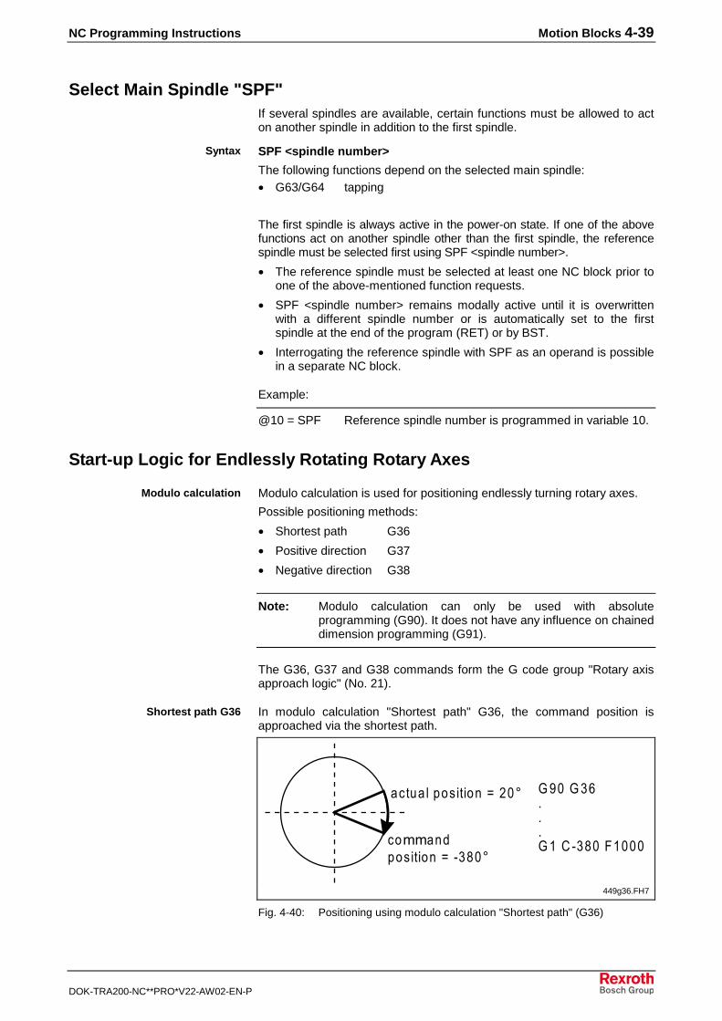
NC Programming Instructions Motion Blocks 4-39
DOK-TRA200-NC**PRO*V22-AW02-EN-P
Select Main Spindle "SPF"If several spindles are available, certain functions must be allowed to acton another spindle in addition to the first spindle.
SPF <spindle number>
The following functions depend on the selected main spindle:• G63/G64 tapping
The first spindle is always active in the power-on state. If one of the abovefunctions act on another spindle other than the first spindle, the referencespindle must be selected first using SPF <spindle number>.
• The reference spindle must be selected at least one NC block prior toone of the above-mentioned function requests.
• SPF <spindle number> remains modally active until it is overwrittenwith a different spindle number or is automatically set to the firstspindle at the end of the program (RET) or by BST.
• Interrogating the reference spindle with SPF as an operand is possiblein a separate NC block.
Example:
@10 = SPF Reference spindle number is programmed in variable 10.
Start-up Logic for Endlessly Rotating Rotary Axes
Modulo calculation is used for positioning endlessly turning rotary axes.
Possible positioning methods:
• Shortest path G36
• Positive direction G37
• Negative direction G38
Note: Modulo calculation can only be used with absoluteprogramming (G90). It does not have any influence on chaineddimension programming (G91).
The G36, G37 and G38 commands form the G code group "Rotary axisapproach logic" (No. 21).
In modulo calculation "Shortest path" G36, the command position isapproached via the shortest path.
���4� ���-� ���-� �2 ���=
�->>�� �-����-� �2 �"�!�=
%&��%� ���% ��/ "�!��:����
449g36.FH7
Fig. 4-40: Positioning using modulo calculation "Shortest path" (G36)
Syntax
Modulo calculation
Shortest path G36
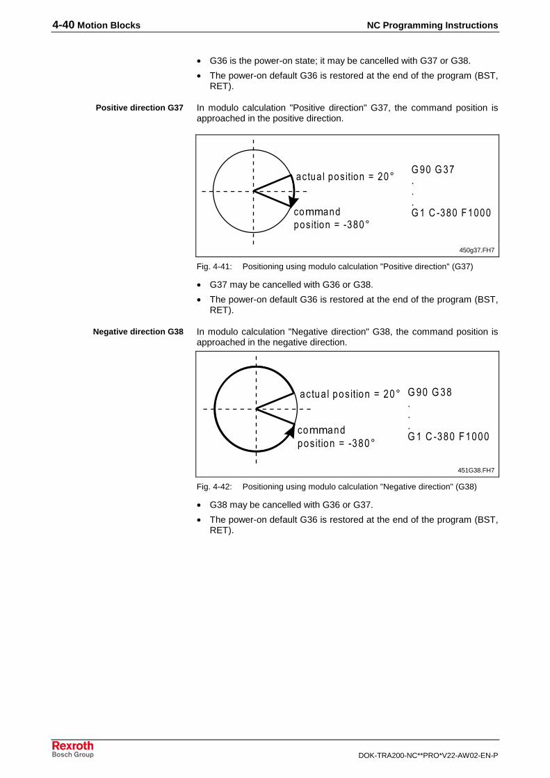
4-40 Motion Blocks NC Programming Instructions
DOK-TRA200-NC**PRO*V22-AW02-EN-P
• G36 is the power-on state; it may be cancelled with G37 or G38.
• The power-on default G36 is restored at the end of the program (BST,RET).
In modulo calculation "Positive direction" G37, the command position isapproached in the positive direction.
���4� ���-� ���-� �2 ���=
�->>�� �-����-� �2 �"�!�=
%&��%�����% ��/ "�!��:����
450g37.FH7
Fig. 4-41: Positioning using modulo calculation "Positive direction" (G37)
• G37 may be cancelled with G36 or G38.
• The power-on default G36 is restored at the end of the program (BST,RET).
In modulo calculation "Negative direction" G38, the command position isapproached in the negative direction.
���4� ���-� ���-� �2 ���=
�->>�� �-����-� �2 �"�!�=
%&��%�!���% ��/ "�!��:����
451G38.FH7
Fig. 4-42: Positioning using modulo calculation "Negative direction" (G38)
• G38 may be cancelled with G36 or G37.
• The power-on default G36 is restored at the end of the program (BST,RET).
Positive direction G37
Negative direction G38
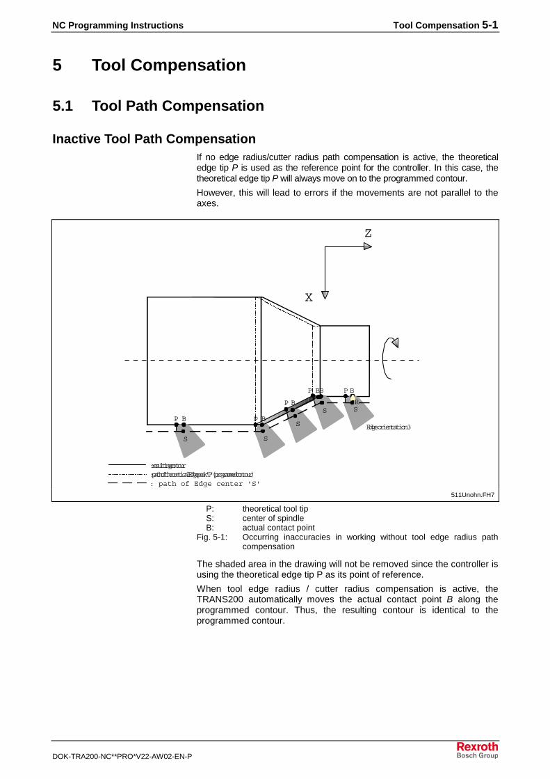
NC Programming Instructions Tool Compensation 5-1
DOK-TRA200-NC**PRO*V22-AW02-EN-P
5 Tool Compensation
5.1 Tool Path Compensation
Inactive Tool Path CompensationIf no edge radius/cutter radius path compensation is active, the theoreticaledge tip P is used as the reference point for the controller. In this case, thetheoretical edge tip P will always move on to the programmed contour.
However, this will lead to errors if the movements are not parallel to theaxes.
: path of theoretical Edge peak 'P' (programmed contour)
Edge orientation 3
SS
S
SS
P B P B
P B
P B B P B
R
: resulting contour
: path of Edge center 'S'
Z
X
511Unohn.FH7
P: theoretical tool tipS: center of spindleB: actual contact point
Fig. 5-1: Occurring inaccuracies in working without tool edge radius pathcompensation
The shaded area in the drawing will not be removed since the controller isusing the theoretical edge tip P as its point of reference.
When tool edge radius / cutter radius compensation is active, theTRANS200 automatically moves the actual contact point B along theprogrammed contour. Thus, the resulting contour is identical to theprogrammed contour.
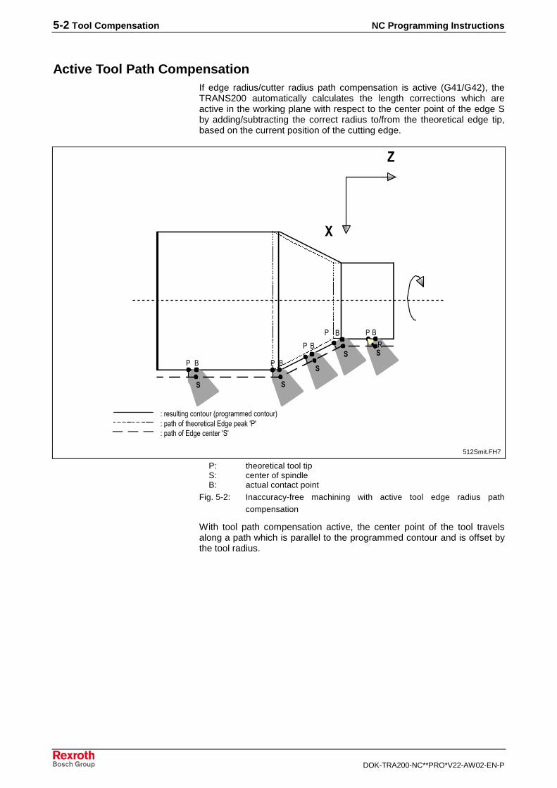
5-2 Tool Compensation NC Programming Instructions
DOK-TRA200-NC**PRO*V22-AW02-EN-P
Active Tool Path CompensationIf edge radius/cutter radius path compensation is active (G41/G42), theTRANS200 automatically calculates the length corrections which areactive in the working plane with respect to the center point of the edge Sby adding/subtracting the correct radius to/from the theoretical edge tip,based on the current position of the cutting edge.
��
�
��
� � � �
� �
� � � �
�
������� ���� ������������������ ������������������������������������������������������� �������
�
�
512Smit.FH7
P: theoretical tool tipS: center of spindleB: actual contact point
Fig. 5-2: Inaccuracy-free machining with active tool edge radius pathcompensation
With tool path compensation active, the center point of the tool travelsalong a path which is parallel to the programmed contour and is offset bythe tool radius.
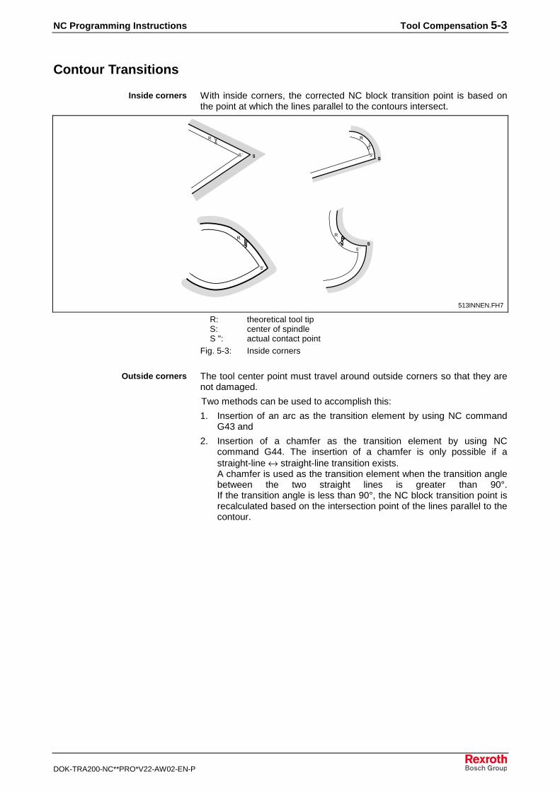
NC Programming Instructions Tool Compensation 5-3
DOK-TRA200-NC**PRO*V22-AW02-EN-P
Contour Transitions
With inside corners, the corrected NC block transition point is based onthe point at which the lines parallel to the contours intersect.
�
��� �
�
����
�
�
�
�
��
��
�
513INNEN.FH7
R: theoretical tool tipS: center of spindleS ": actual contact point
Fig. 5-3: Inside corners
The tool center point must travel around outside corners so that they arenot damaged.
Two methods can be used to accomplish this:
1. Insertion of an arc as the transition element by using NC commandG43 and
2. Insertion of a chamfer as the transition element by using NCcommand G44. The insertion of a chamfer is only possible if astraight-line ↔ straight-line transition exists.A chamfer is used as the transition element when the transition anglebetween the two straight lines is greater than 90°.If the transition angle is less than 90°, the NC block transition point isrecalculated based on the intersection point of the lines parallel to thecontour.
Inside corners
Outside corners
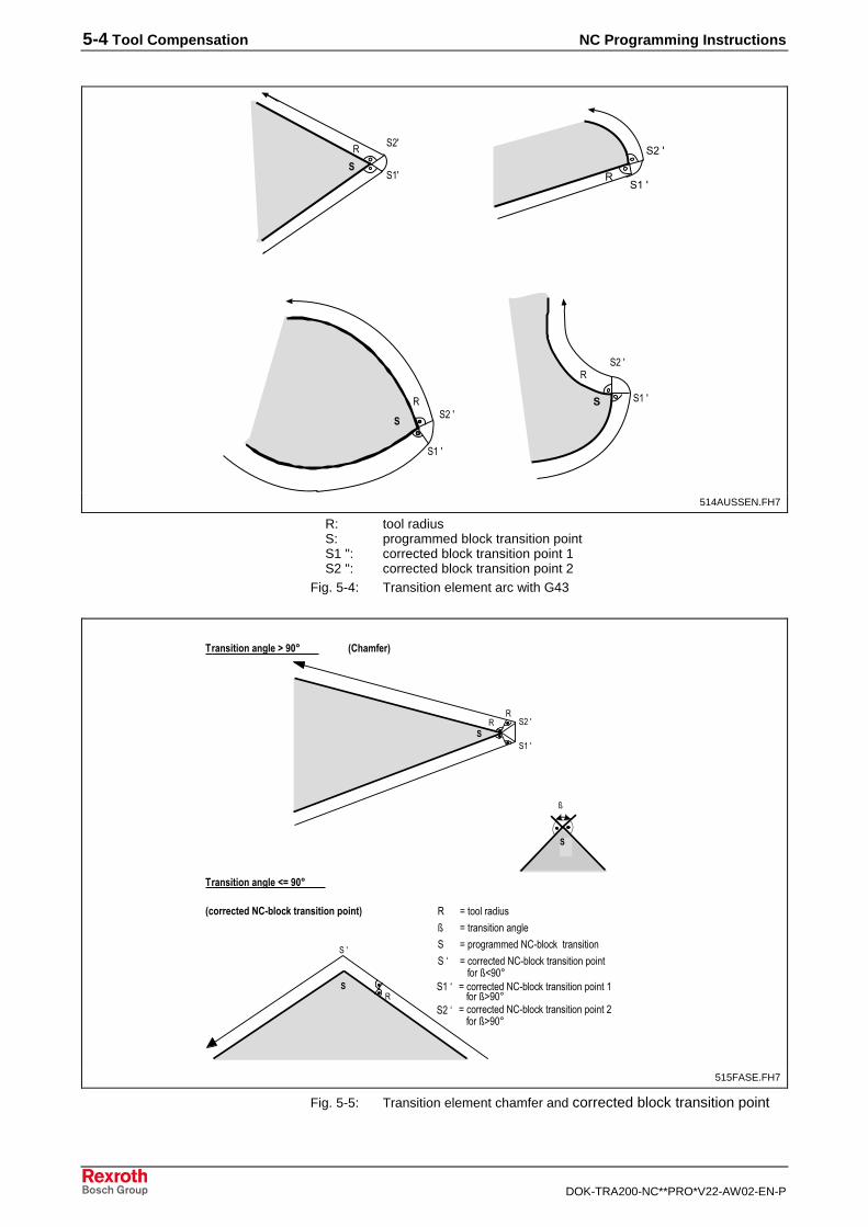
5-4 Tool Compensation NC Programming Instructions
DOK-TRA200-NC**PRO*V22-AW02-EN-P
�
����
����
�
�
�
��� !� "��#
�
����
�$��
�$�����
�
����
�$��
514AUSSEN.FH7
R: tool radiusS: programmed block transition pointS1 ": corrected block transition point 1S2 ": corrected block transition point 2
Fig. 5-4: Transition element arc with G43
%������������&'()�������� ����� %�����������&'()������� ����� ���� ��������!*+,-%�����������&'()������� ����� ���� ����������!.+,-%�����������&'()������� ����� ���� ��$�������!.+,-
��
�����
�$��
�
���
�
���������� �������� ���������
���������� ���������
������������� ���!��������"��� %����������%���� ����� �� ��
�!���/
���/
�$�/
!
����0���"��#
515FASE.FH7
Fig. 5-5: Transition element chamfer and corrected block transition point
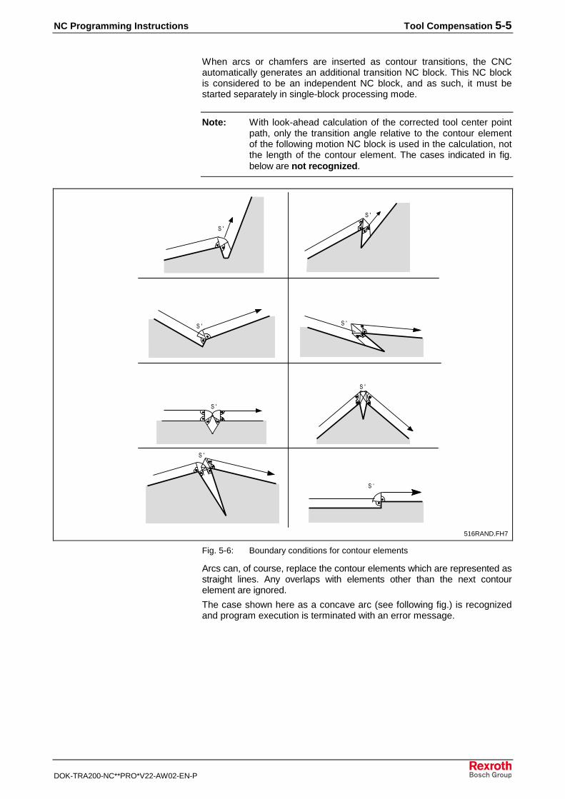
NC Programming Instructions Tool Compensation 5-5
DOK-TRA200-NC**PRO*V22-AW02-EN-P
When arcs or chamfers are inserted as contour transitions, the CNCautomatically generates an additional transition NC block. This NC blockis considered to be an independent NC block, and as such, it must bestarted separately in single-block processing mode.
Note: With look-ahead calculation of the corrected tool center pointpath, only the transition angle relative to the contour elementof the following motion NC block is used in the calculation, notthe length of the contour element. The cases indicated in fig.below are not recognized.
���
���
��� ���
���
���
��/
���
��1�� �"��#
516RAND.FH7
Fig. 5-6: Boundary conditions for contour elements
Arcs can, of course, replace the contour elements which are represented asstraight lines. Any overlaps with elements other than the next contourelement are ignored.
The case shown here as a concave arc (see following fig.) is recognizedand program execution is terminated with an error message.
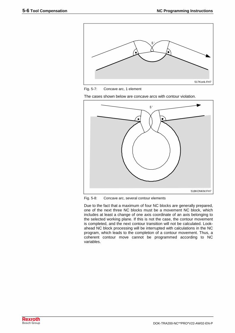
5-6 Tool Compensation NC Programming Instructions
DOK-TRA200-NC**PRO*V22-AW02-EN-P
���
��#2� �"��#
517Konk.FH7
Fig. 5-7: Concave arc, 1 element
The cases shown below are concave arcs with contour violation.
���
��32� �4"��#
518KONKM.FH7
Fig. 5-8: Concave arc, several contour elements
Due to the fact that a maximum of four NC blocks are generally prepared,one of the next three NC blocks must be a movement NC block, whichincludes at least a change of one axis coordinate of an axis belonging tothe selected working plane. If this is not the case, the contour movementis completed, and the next contour transition will not be calculated. Look-ahead NC block processing will be interrupted with calculations in the NCprogram, which leads to the completion of a contour movement. Thus, acoherent contour move cannot be programmed according to NCvariables.
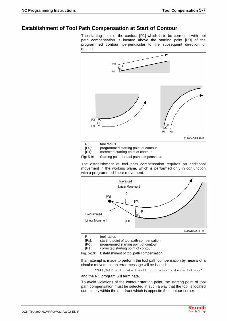
NC Programming Instructions Tool Compensation 5-7
DOK-TRA200-NC**PRO*V22-AW02-EN-P
Establishment of Tool Path Compensation at Start of ContourThe starting point of the contour [P1] which is to be corrected with toolpath compensation is located above the starting point [P0] of theprogrammed contour, perpendicular to the subsequent direction ofmotion.
�5��6
5�,6
�5�,6
5��6 �
5�,6 5��6
��+7
2���"��#
519WKORR.FH7
R: tool radius[P0]: programmed starting point of contour[P1]: corrected starting point of contour
Fig: 5-9: Starting point for tool path compensation
The establishment of tool path compensation requires an additionalmovement in the working plane, which is performed only in conjunctionwith a programmed linear movement.
�
5�,6
5��65��6
8��9�����
:� ����4�9��� �
:� ����4�9��� �
����������
�$,7
2��"��#
520WKAUF.FH7
R: tool radius[Ps]: starting point of tool path compensation[P0]: programmed starting point of contour[P1]: corrected starting point of contour
Fig. 5-10: Establishment of tool path compensation
If an attempt is made to perform the tool path compensation by means of acircular movement, an error message will be issued:
"G41/G42 activated with circular interpolation"
and the NC program will terminate.
To avoid violations of the contour starting point, the starting point of toolpath compensation must be selected in such a way that the tool is locatedcompletely within the quadrant which is opposite the contour corner.
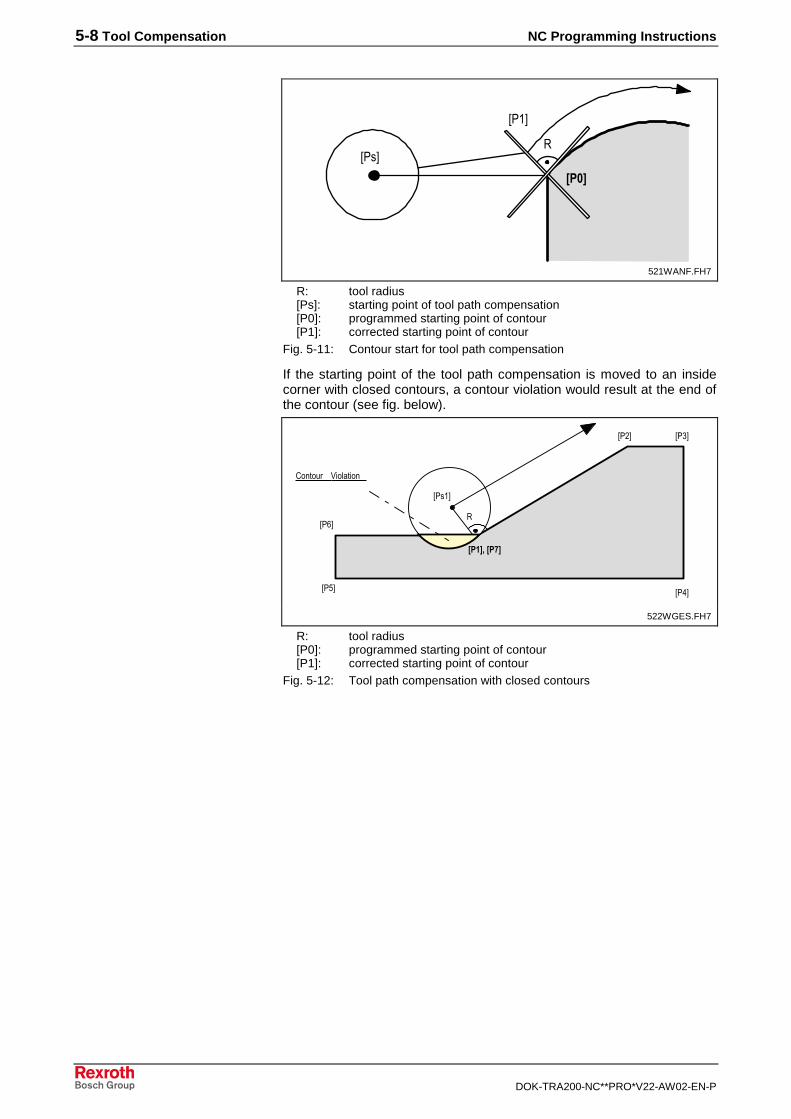
5-8 Tool Compensation NC Programming Instructions
DOK-TRA200-NC**PRO*V22-AW02-EN-P
#$�%
5��6
�5��6
�$�7
� �"��#
521WANF.FH7
R: tool radius[Ps]: starting point of tool path compensation[P0]: programmed starting point of contour[P1]: corrected starting point of contour
Fig. 5-11: Contour start for tool path compensation
If the starting point of the tool path compensation is moved to an insidecorner with closed contours, a contour violation would result at the end ofthe contour (see fig. below).
#$&%'�#$(%
5�$6 5�;6
5��65��6
5�16
5���6
�
'� ���� <������
�$$7
���"��#
522WGES.FH7
R: tool radius[P0]: programmed starting point of contour[P1]: corrected starting point of contour
Fig. 5-12: Tool path compensation with closed contours
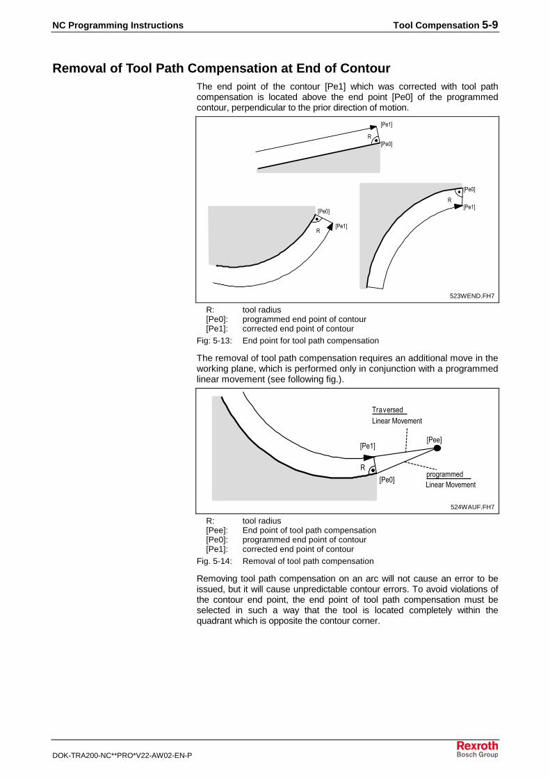
NC Programming Instructions Tool Compensation 5-9
DOK-TRA200-NC**PRO*V22-AW02-EN-P
Removal of Tool Path Compensation at End of ContourThe end point of the contour [Pe1] which was corrected with tool pathcompensation is located above the end point [Pe0] of the programmedcontour, perpendicular to the prior direction of motion.
�
5���6
5��,6
�
5��,6
5���6
�
5��,6
5���6�$;7
� �"��#
523WEND.FH7
R: tool radius[Pe0]: programmed end point of contour[Pe1]: corrected end point of contour
Fig: 5-13: End point for tool path compensation
The removal of tool path compensation requires an additional move in theworking plane, which is performed only in conjunction with a programmedlinear movement (see following fig.).
�
5��,6
5���65���6
8��9�����:� ����4�9��� �
����������:� ����4�9��� �
�$�7
�"��#
524WAUF.FH7
R: tool radius[Pee]: End point of tool path compensation[Pe0]: programmed end point of contour[Pe1]: corrected end point of contour
Fig. 5-14: Removal of tool path compensation
Removing tool path compensation on an arc will not cause an error to beissued, but it will cause unpredictable contour errors. To avoid violations ofthe contour end point, the end point of tool path compensation must beselected in such a way that the tool is located completely within thequadrant which is opposite the contour corner.

5-10 Tool Compensation NC Programming Instructions
DOK-TRA200-NC**PRO*V22-AW02-EN-P
5��,6
5���6
�
5���6
�$�2� ��"��#
525KENDE.FH7
R: tool radius[Pee]: End point of tool path compensation[Pe0]: programmed end point of contour[Pe1]: corrected end point of contour
Fig. 5-15: Contour end for tool path compensation
If the end point of the tool path compensation is moved to an insidecorner with closed contours, a contour violation would result at the startingpoint of the contour (see following fig.).
#$&%'�#$(%
5�$6 5�;6
5��65��6
5�16
5��#6
�
'� ���� <������
�$12�����"��#
526KGESCH.FH7
R: tool radius[P7]: programmed end point of contour[Pe7]: corrected end point of contour
Fig. 5-16: Tool path compensation with closed contours
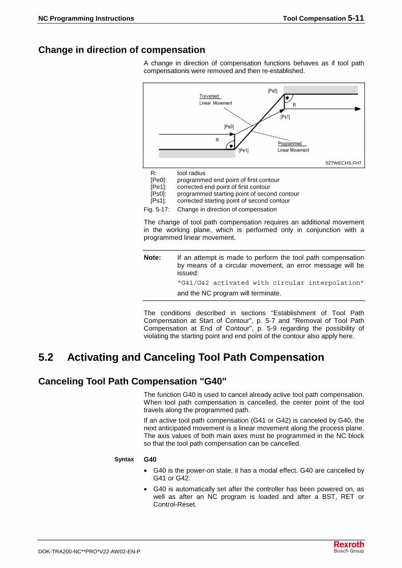
NC Programming Instructions Tool Compensation 5-11
DOK-TRA200-NC**PRO*V22-AW02-EN-P
Change in direction of compensationA change in direction of compensation functions behaves as if tool pathcompensationis were removed and then re-established.
5��,6
5���6
�
�
5��,6
5���6����������:� ����4�9��� �
8��9�����:� �����4�9��� �
�$#7
����"��#
527WECHS.FH7
R: tool radius[Pe0]: programmed end point of first contour[Pe1]: corrected end point of first contour[Ps0]: programmed starting point of second contour[Ps1]: corrected starting point of second contour
Fig. 5-17: Change in direction of compensation
The change of tool path compensation requires an additional movementin the working plane, which is performed only in conjunction with aprogrammed linear movement.
Note: If an attempt is made to perform the tool path compensationby means of a circular movement, an error message will beissued:"G41/G42 activated with circular interpolation"
and the NC program will terminate.
The conditions described in sections "Establishment of Tool PathCompensation at Start of Contour", p. 5-7 and "Removal of Tool PathCompensation at End of Contour", p. 5-9 regarding the possibility ofviolating the starting point and end point of the contour also apply here.
5.2 Activating and Canceling Tool Path Compensation
Canceling Tool Path Compensation "G40"The function G40 is used to cancel already active tool path compensation.When tool path compensation is cancelled, the center point of the tooltravels along the programmed path.
If an active tool path compensation (G41 or G42) is canceled by G40, thenext anticipated movement is a linear movement along the process plane.The axis values of both main axes must be programmed in the NC blockso that the tool path compensation can be cancelled.
G40
• G40 is the power-on state; it has a modal effect. G40 are cancelled byG41 or G42.
• G40 is automatically set after the controller has been powered on, aswell as after an NC program is loaded and after a BST, RET orControl-Reset.
Syntax
5-12 Tool Compensation NC Programming Instructions
DOK-TRA200-NC**PRO*V22-AW02-EN-P
Tool Path Compensation, Left "G41"Tool path compensation to the left of the workpiece contour is activatedby the G41 function command.
If tool path compensation to the left of the contour is active, the tool centerpoint moves along the left side of the programmed contour when viewedin the direction of movement. It moves along a path opposite of andparallel to the contour with an offset equaling the tool radius.
If G41 is programmed after an active G40 or G42, the next anticipatedmovement is a linear movement in the process plane. The axis values ofboth main axes must be programmed in the NC block in order for the toolpath compensation to be re-established or changed.
G41
• G41 remains modally active until it is canceled by G40 or G42 or untila reset is automatically performed at the end of the program (RET) orBST.
• When tool path compensation is active, no more than two NC blockscan be programmed without programming a movement in the currentprocess plane. If more than two NC blocks are programmed without amovement, tool path compensation is canceled with G40.
Note: If an attempt is made to perform the tool path compensationby means of a circular movement, an error message will beissued:"G41/G42 activated with circularinterpolation"
and the NC program will terminate.
Tool Path Compensation, Right "G42"Tool path compensation to the right of the workpiece contour is activatedby the G42 function command.
If tool path compensation to the right of the contour is active, the toolcenter point moves along the right side of the programmed contour whenviewed in the direction of movement. It moves along a path opposite ofand parallel to the contour with an offset equaling the tool radius.
If G42 is programmed after an active tool path compensation (G40 orG41), the next anticipated movement is a linear movement on theprocess plane. The axis values of both main axes must be programmedin the NC block so that tool path compensation can be activated orchanged.
G42
• G42 remains modally active until it is canceled by G40 or G41 or untila reset is automatically performed at the end of the program (RET) orBST.
• When tool path compensation is active, no more than two NC blockscan be programmed without programming a movement in the currentprocess plane. If more than two NC blocks are programmed without amovement, tool path compensation is canceled with G40.
Syntax
Syntax
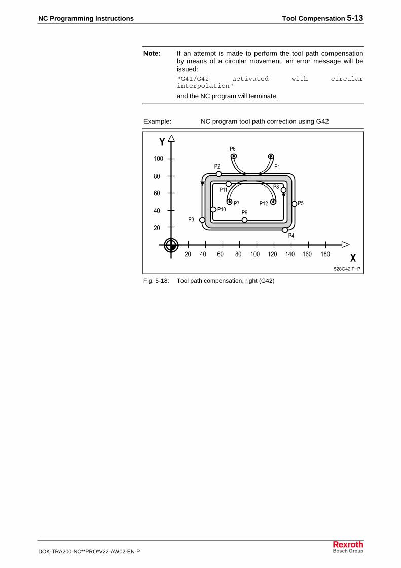
NC Programming Instructions Tool Compensation 5-13
DOK-TRA200-NC**PRO*V22-AW02-EN-P
Note: If an attempt is made to perform the tool path compensationby means of a circular movement, an error message will beissued:"G41/G42 activated with circularinterpolation"
and the NC program will terminate.
Example: NC program tool path correction using G42
$,
�,
1,
3,
�,,
$, �, 1, 3, �,, �
)
�$, ��, �1, �3,
��
�1
�3
��
��
�+��,
�$
���
�;
��$�#
�$3=�$"��#
528G42.FH7
Fig. 5-18: Tool path compensation, right (G42)
5-14 Tool Compensation NC Programming Instructions
DOK-TRA200-NC**PRO*V22-AW02-EN-P
NC program using G42:
G00 G54 G06 G08 X115 Y99.5 Z5 motion commands, interpolationconditions
G01 Z2 F1000 S2000 M0 1. start position
Z-10 F1200 immerse milling machine
G42 X117.5 Y99.5 F1500 [P1] establishment of tool pathcompensation
G02 X98 Y80 I98 J99.5 approaching contour with ¼ circle
G01 X45 Y80 [P2] machining of 1. section
G03 X40 Y75 I45 J75 machining of 1. ¼ circle
G01 X40 Y25 [P3] machining of 2. section
G03 X45 Y20 I45 J25 machining of 2. ¼ circle
G01 X135 Y20 [P4] machining of 3. section
G03 X140 Y25 I135 J25 machining of 3. ¼ circle
G01 X140 Y75 [P5] machining of 4. section
G03 X135 Y80 I135 J75 machining of 4. ¼ circle
G01 X90 Y80 machining of 5. section
G02 X73.5 Y96.5 I90 J96.5 departing contour with ¼ circle
G01 X73.5 Y99.5 [P6] end position of outsidecontour
G00 Z2 Z axis to safety distance
G40 X68 Y49.5 [P7] start position of inside contour
G01 Z-10 F1000 immerse milling machine
G42 X65.5 Y49.5 F1500 establishment of tool pathcompensation
X65.5 Y50.5 linear movement
G02 X90 Y75 I90 J50,5 approaching contour with ¼ circle
G01 X130 Y75 [P8] machining of 1. section
G02 X135 Y70 I130 J70 machining of 1. ¼ circle
G01 X135 Y30 [P9] machining of 2. section
G02 X130 Y25 I130 J30 machining of 2. ¼ circle
G01 X50 Y25 [P10] machining of 3. section
G02 X45 Y30 I50 J30 machining of 3. ¼ circle
G01 X45 Y70 [P11] machining of 4. section
G02 X50 Y75 I50 J70 machining of 4. ¼ circle
G01 X98 Y75 machining of 5. section
G02 X119.5 Y53.5 I98 J53.5 departing contour with ¼ circle
G01 X119.5 Y49.5 [P6] end position of outsidecontour
G00 Z2 Z axis to safety distance
RET program end
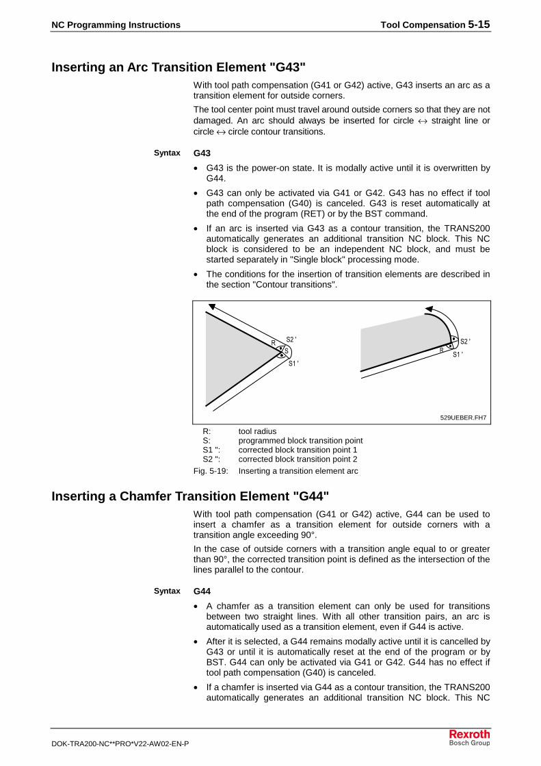
NC Programming Instructions Tool Compensation 5-15
DOK-TRA200-NC**PRO*V22-AW02-EN-P
Inserting an Arc Transition Element "G43"With tool path compensation (G41 or G42) active, G43 inserts an arc as atransition element for outside corners.
The tool center point must travel around outside corners so that they are notdamaged. An arc should always be inserted for circle ↔ straight line orcircle ↔ circle contour transitions.
G43
• G43 is the power-on state. It is modally active until it is overwritten byG44.
• G43 can only be activated via G41 or G42. G43 has no effect if toolpath compensation (G40) is canceled. G43 is reset automatically atthe end of the program (RET) or by the BST command.
• If an arc is inserted via G43 as a contour transition, the TRANS200automatically generates an additional transition NC block. This NCblock is considered to be an independent NC block, and must bestarted separately in "Single block" processing mode.
• The conditions for the insertion of transition elements are described inthe section "Contour transitions".
��
�$��
��������
�$���
�$+>)��"��#
529UEBER.FH7
R: tool radiusS: programmed block transition pointS1 ": corrected block transition point 1S2 ": corrected block transition point 2
Fig. 5-19: Inserting a transition element arc
Inserting a Chamfer Transition Element "G44"With tool path compensation (G41 or G42) active, G44 can be used toinsert a chamfer as a transition element for outside corners with atransition angle exceeding 90°.
In the case of outside corners with a transition angle equal to or greaterthan 90°, the corrected transition point is defined as the intersection of thelines parallel to the contour.
G44
• A chamfer as a transition element can only be used for transitionsbetween two straight lines. With all other transition pairs, an arc isautomatically used as a transition element, even if G44 is active.
• After it is selected, a G44 remains modally active until it is cancelled byG43 or until it is automatically reset at the end of the program or byBST. G44 can only be activated via G41 or G42. G44 has no effect iftool path compensation (G40) is canceled.
• If a chamfer is inserted via G44 as a contour transition, the TRANS200automatically generates an additional transition NC block. This NC
Syntax
Syntax
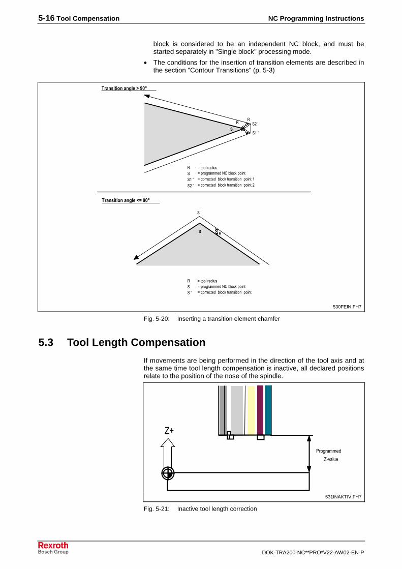
5-16 Tool Compensation NC Programming Instructions
DOK-TRA200-NC**PRO*V22-AW02-EN-P
block is considered to be an independent NC block, and must bestarted separately in "Single block" processing mode.
• The conditions for the insertion of transition elements are described inthe section "Contour Transitions" (p. 5-3)
�%�����������%������������&'�)������� �
�%������������)������� ����� ����� ��$
������ �%������������)������� ����� ����� ���
�$��
��
�����
�$��
�%�����������%������������&'�)������� �
����� �%������������)������� ����� ����� �
�
���
�
���������� ��������
���������� ���������
�;,0�� "��#
530FEIN.FH7
Fig. 5-20: Inserting a transition element chamfer
5.3 Tool Length Compensation
If movements are being performed in the direction of the tool axis and atthe same time tool length compensation is inactive, all declared positionsrelate to the position of the nose of the spindle.
����������
?(9��
?@
�;�� ����9"��#
531INAKTIV.FH7
Fig. 5-21: Inactive tool length correction
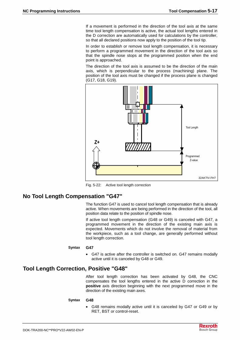
NC Programming Instructions Tool Compensation 5-17
DOK-TRA200-NC**PRO*V22-AW02-EN-P
If a movement is performed in the direction of the tool axis at the sametime tool length compensation is active, the actual tool lengths entered inthe D correction are automatically used for calculations by the controller,so that all declared positions now apply to the position of the tool tip.
In order to establish or remove tool length compensation, it is necessaryto perform a programmed movement in the direction of the tool axis sothat the spindle nose stops at the programmed position when the endpoint is approached.
The direction of the tool axis is assumed to be the direction of the mainaxis, which is perpendicular to the process (machining) plane. Theposition of the tool axis must be changed if the process plane is changed(G17, G18, G19).
�*
����������?(9��
8���:� ���
�;$����9"��#
32AKTIV.FH7
Fig. 5-22: Active tool length correction
No Tool Length Compensation "G47"The function G47 is used to cancel tool length compensation that is alreadyactive. When movements are being performed in the direction of the tool, allposition data relate to the position of spindle nose.
If active tool length compensation (G48 or G49) is canceled with G47, aprogrammed movement in the direction of the existing main axis isexpected. Movements which do not involve the removal of material fromthe workpiece, such as a tool change, are generally performed withouttool length correction.
G47
• G47 is active after the controller is switched on. G47 remains modallyactive until it is canceled by G48 or G49.
Tool Length Correction, Positive "G48"After tool length correction has been activated by G48, the CNCcompensates the tool lengths entered in the active D correction in thepositive axis direction beginning with the next programmed move in thedirection of the existing main axes.
G48
• G48 remains modally active until it is canceled by G47 or G49 or byRET, BST or control-reset.
Syntax
Syntax
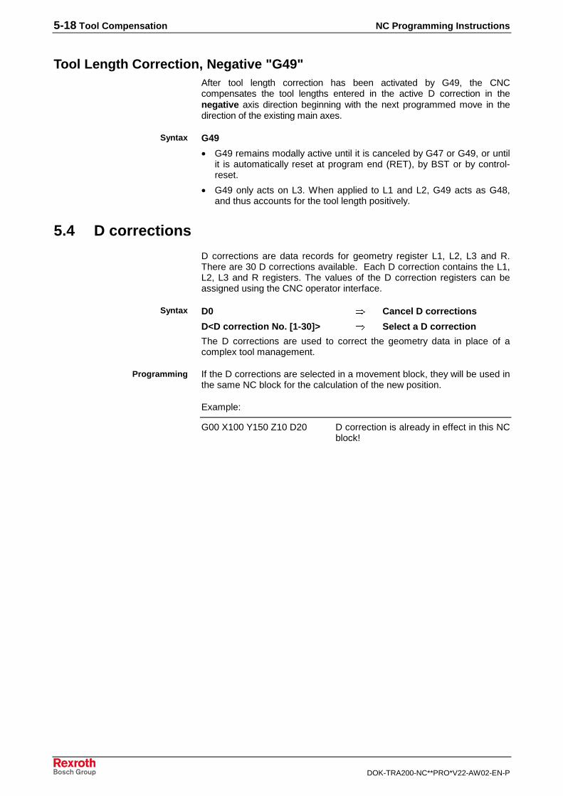
5-18 Tool Compensation NC Programming Instructions
DOK-TRA200-NC**PRO*V22-AW02-EN-P
Tool Length Correction, Negative "G49"After tool length correction has been activated by G49, the CNCcompensates the tool lengths entered in the active D correction in thenegative axis direction beginning with the next programmed move in thedirection of the existing main axes.
G49
• G49 remains modally active until it is canceled by G47 or G49, or untilit is automatically reset at program end (RET), by BST or by control-reset.
• G49 only acts on L3. When applied to L1 and L2, G49 acts as G48,and thus accounts for the tool length positively.
5.4 D corrections
D corrections are data records for geometry register L1, L2, L3 and R.There are 30 D corrections available. Each D correction contains the L1,L2, L3 and R registers. The values of the D correction registers can beassigned using the CNC operator interface.
D0 � Cancel D corrections
D<D correction No. [1-30]> � Select a D correction
The D corrections are used to correct the geometry data in place of acomplex tool management.
If the D corrections are selected in a movement block, they will be used inthe same NC block for the calculation of the new position.
Example:
G00 X100 Y150 Z10 D20 D correction is already in effect in this NCblock!
Syntax
Syntax
Programming

NC Programming Instructions Tool Compensation 5-19
DOK-TRA200-NC**PRO*V22-AW02-EN-P
��
��
�� �
�
�
��
��
�� �
�
�
�
��
��
�� �
�
�
����� ��� ���
��
Ebene.FH7
Fig. 5-23: How D corrections work in the corresponding machining plane
Geometry registers L1, L2 and L3 are not used for compensation unlesstool length correction G48/G49 is active. Geometry register R is only usedfor compensation when tool path compensation G41/G42 is active.
If tool management is active for a selected machining tool and a Dcorrection is also active, then the tool lengths and the radius arecalculated as follows:
correction D of R R Offset R Wear R Radius R oncompensati Radius
correction D of L3 L3 Offset L3 Wear L3 Length L3 oncompensati Length
correction D of L2 L2 Offset L2 Wear L2 Length L2 oncompensati Length
correction D of L1 L1 Offset L1 Wear L1 Length L1 oncompensati Length
+++=+++=+++=
+++=
Fig. 5-24: Calculation of length and radius
How D corrections work
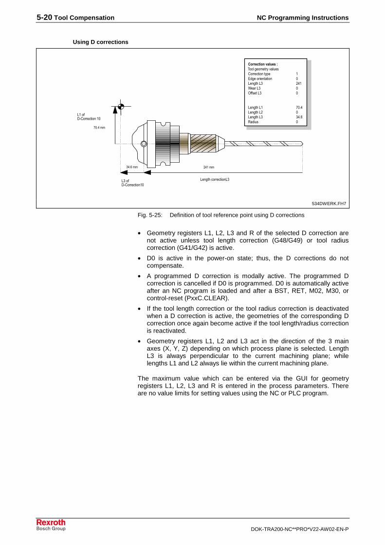
5-20 Tool Compensation NC Programming Instructions
DOK-TRA200-NC**PRO*V22-AW02-EN-P
:;���A('�������� �,
:� ������������� :;
:����A('�������� ��,
$�����;�"1���
#,"����
7���B�����������C�������������+��,���-
'�������� ��D�� ���������� ����� ,:� ����:; $��7����:; ,E������:; ,
:� ����:� #,"�:� ����:$ ,:� ����:; ;�"1����� ,
8����������D�9����;�AC���"��#
534DWERK.FH7
Fig. 5-25: Definition of tool reference point using D corrections
• Geometry registers L1, L2, L3 and R of the selected D correction arenot active unless tool length correction (G48/G49) or tool radiuscorrection (G41/G42) is active.
• D0 is active in the power-on state; thus, the D corrections do notcompensate.
• A programmed D correction is modally active. The programmed Dcorrection is cancelled if D0 is programmed. D0 is automatically activeafter an NC program is loaded and after a BST, RET, M02, M30, orcontrol-reset (PxxC.CLEAR).
• If the tool length correction or the tool radius correction is deactivatedwhen a D correction is active, the geometries of the corresponding Dcorrection once again become active if the tool length/radius correctionis reactivated.
• Geometry registers L1, L2 and L3 act in the direction of the 3 mainaxes (X, Y, Z) depending on which process plane is selected. LengthL3 is always perpendicular to the current machining plane; whilelengths L1 and L2 always lie within the current machining plane.
The maximum value which can be entered via the GUI for geometryregisters L1, L2, L3 and R is entered in the process parameters. Thereare no value limits for setting values using the NC or PLC program.
Using D corrections
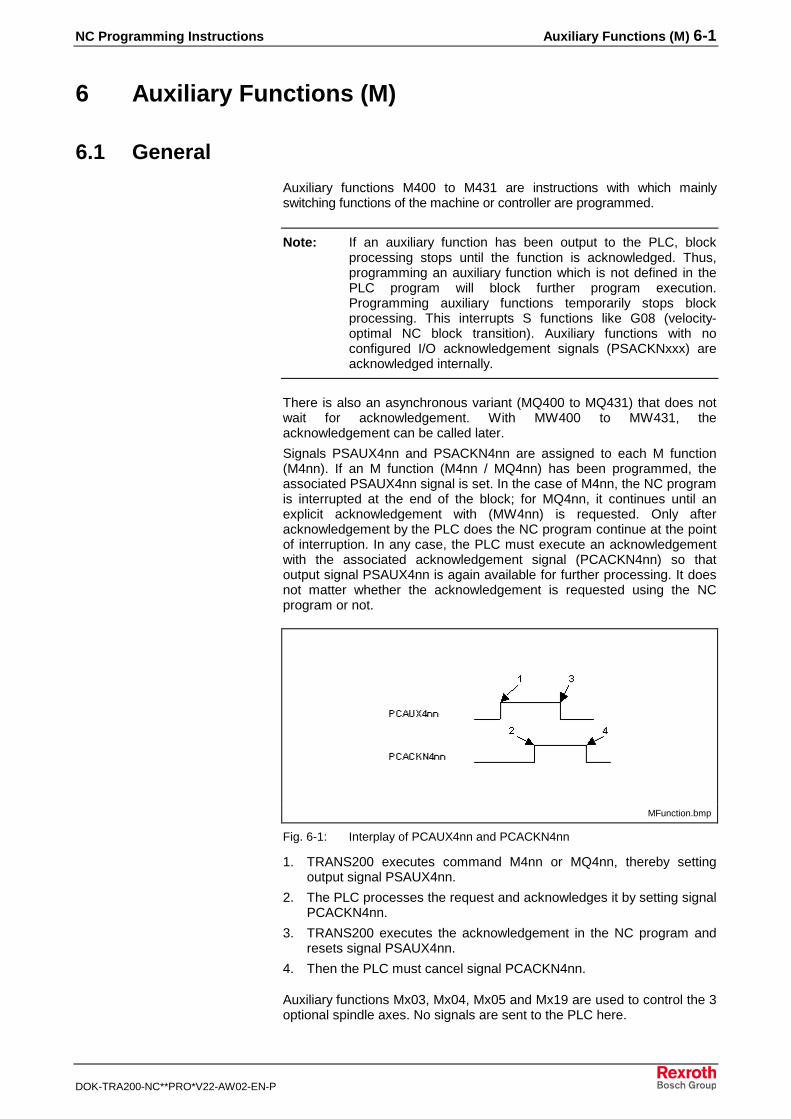
NC Programming Instructions Auxiliary Functions (M) 6-1
DOK-TRA200-NC**PRO*V22-AW02-EN-P
6 Auxiliary Functions (M)
6.1 General
Auxiliary functions M400 to M431 are instructions with which mainlyswitching functions of the machine or controller are programmed.
Note: If an auxiliary function has been output to the PLC, blockprocessing stops until the function is acknowledged. Thus,programming an auxiliary function which is not defined in thePLC program will block further program execution.Programming auxiliary functions temporarily stops blockprocessing. This interrupts S functions like G08 (velocity-optimal NC block transition). Auxiliary functions with noconfigured I/O acknowledgement signals (PSACKNxxx) areacknowledged internally.
There is also an asynchronous variant (MQ400 to MQ431) that does notwait for acknowledgement. With MW400 to MW431, theacknowledgement can be called later.
Signals PSAUX4nn and PSACKN4nn are assigned to each M function(M4nn). If an M function (M4nn / MQ4nn) has been programmed, theassociated PSAUX4nn signal is set. In the case of M4nn, the NC programis interrupted at the end of the block; for MQ4nn, it continues until anexplicit acknowledgement with (MW4nn) is requested. Only afteracknowledgement by the PLC does the NC program continue at the pointof interruption. In any case, the PLC must execute an acknowledgementwith the associated acknowledgement signal (PCACKN4nn) so thatoutput signal PSAUX4nn is again available for further processing. It doesnot matter whether the acknowledgement is requested using the NCprogram or not.
MFunction.bmp
Fig. 6-1: Interplay of PCAUX4nn and PCACKN4nn
1. TRANS200 executes command M4nn or MQ4nn, thereby settingoutput signal PSAUX4nn.
2. The PLC processes the request and acknowledges it by setting signalPCACKN4nn.
3. TRANS200 executes the acknowledgement in the NC program andresets signal PSAUX4nn.
4. Then the PLC must cancel signal PCACKN4nn.
Auxiliary functions Mx03, Mx04, Mx05 and Mx19 are used to control the 3optional spindle axes. No signals are sent to the PLC here.

6-2 Auxiliary Functions (M) NC Programming Instructions
DOK-TRA200-NC**PRO*V22-AW02-EN-P
M Function M FunctionGroup
Effect Meaning
- 1 - -
M003, M004, M005 2 modal Spindle S
M103, M104, M105 2 modal Spindle S1
M203, M204, M205 3 modal Spindle S2
M303, M304, M305 4 modal Spindle S3
M400, M401, M402, M403 5 modal Auxiliary Functions 400-403
M404, M405, M406, M407 6 modal Auxiliary Functions 404-407
M408, M409, M410, M411 7 modal Auxiliary Functions 408-411
M412, M413, M414, M415 8 modal Auxiliary Functions 412-415
M416, M417, M418, M419 9 modal Auxiliary Functions 416-419
M420, M421, M422, M423 10 modal Auxiliary Functions 420-423
M424, M425, M426, M427 14 modal Auxiliary Functions 424-427
M428, M429, M430, M431 15 modal Auxiliary Functions 428-431
M19, M119, M219, M319, Mxxx 16 blockwise Spindle Positioning
Fig. 6-2: M function groups
All M functions with the exception of spindle control commands Mx03,Mx04, Mx05 and the blockwise active M function Mx19 can be used asdesired by the machine builder since they do not trigger any internalfunctions in the controller.
• In a given NC block, only one M function can be programmed fromeach function group.
• No more than four M functions can be programmed in a single NCblock.
The M functions overwrite one another.
Spindle Control CommandsThe spindle is turned on or off using the spindle control commands M003,M004, M005. The first digit in the M functions is evaluated as the spindleindex number. If the spindle index is 0 (M003), the M function is applied tothe first spindle; if the spindle index is 2 (M203), the M function is applied tothe second spindle.• The spindle control commands Mx03 and Mx04 will already be
effective with an axis movement programmed in the block.
Activate spindle rotation in clockwise direction.
Activate spindle in counterclockwise direction.
Shut off spindle.
Mx03 Spindle in clockwisedirection
Mx04 Spindle incounterclockwise direction
Mx05 spindle stop
NC Programming Instructions Auxiliary Functions (M) 6-3
DOK-TRA200-NC**PRO*V22-AW02-EN-P
Spindle PositioningThe function M19 S... allows the primary spindle to be stopped in adefined position. The angular position is programmed in degrees ataddress S.
The primary spindle can be positioned while not turning as well as whileturning.
• The NC block is only processed completely after Mx19 has beenacknowledged by the PLC, when the spindle has reached theprogrammed end position.
• If Mx19 is programmed without an S word; an error will be issuedwhen the program is executed.
• The function Mx19 is only possible with primary spindles that are ableto be positioned.
M19 S<constant> � M19 S180
M19 S=<expression> � M19 S=@070
M<spind. ind.>19 S<spind. ind.><constant> � M219 S2 90
M<spind. ind.>19 S<spind. ind.>=<expression> � M319 S3=@060
This command initiates asynchronous spindle synchronization. The NCblock that contains MQ19 is terminated as soon as all the other softwarefunctions are executed, even if the spindle has not yet reached theprogrammed end position.
Via the programming of MW19 (with the same spindle position as withMQ19), the following NC block can be interrogated and waited for until thespindle has reached its target position.
If there are several spindles available, only one positioning command canbe started in each NC block. A separate NC block with the correspondingpositioning command (e.g. MQ219) is required for the second and eachadditional spindle.
The following restrictions apply to the MQ19 command:
• May only be used with SERCOS primary spindles with SHS firmware;the parameter S-0-0152 must exist.
Syntax
6-4 Auxiliary Functions (M) NC Programming Instructions
DOK-TRA200-NC**PRO*V22-AW02-EN-P
NC Programming Instructions Events 7-1
DOK-TRA200-NC**PRO*V22-AW02-EN-P
7 Events
7.1 Definition of NC Events
Any events can be set and deleted in PLC program. Waiting for a definedstate in an NC event can synchronize processes.
Therefore, please refer to the machine builder's information regardingevents influenced by the PLC program since the builder may have usedvarious NC events for synchronization purposes.
Note: The event 0 is reserved for the interrupt-controlled programbranching and should generally be kept open for this functions.
No more than four different NC event commands and only one NC eventbranch command may be programmed in one NC block.
Events are specified in the form <Event type>:<Event number>.
The TRANS200 control system differentiates between synchronous andasynchronous events. 31 synchronous (event 1 - 31) and 1 asynchronousevent (event 0) are available. The synchronous events can be binarilycoded with signals PCCOND00, PCCOND01, PCCOND02, PCCOND03,PCCOND04. The asynchronous event is activated with signal PCEVENT.The status of the events can be controlled with the NC screen and themini control panel.
7.2 Influencing Events
Wait until Event is Set "WES"The WES command "Wait until event is set” is used to stop programprocessing until the event defined in the command parameter is set. If theevent is already set, the block continues to process without interruption.
WES <event number[0-31]> => WES 9
• The WES command should not be programmed within a programsection in which tool path compensation is active. If this proves to beunavoidable, be certain that it is only programmed between linearblock transitions.
Wait until Event is Reset "WER"The WER command "Wait until event is reset” is used to stop programprocessing until the event defined in the command parameter is reset. Ifthe NC event is already reset, the block continues to process withoutinterruption.
WER <event number[0-31]> => WER 9
• The WER command should not be programmed within a programsection in which tool path compensation is active. If this proves to beunavoidable, be certain that it is only programmed between linearblock transitions.
Description
Syntax
Syntax
7-2 Events NC Programming Instructions
DOK-TRA200-NC**PRO*V22-AW02-EN-P
7.3 Conditional Branches for Events
Branch if Event is Set "BES"The BES branch command "Branch if event is set" is used to continueprogram processing at the declared branch label if the NC event definedin the command parameter is set.
BES <branch label> <event number[0-31]>=> BES .LABEL 9
7.4 Asynchronous Handling of NC Events
The CNC can use NC event 0 to influence the NC program execution atany desired time. Since the status of events can be changed by the PLC,the NC program can be programmed to branch conditionally upon certainsignal changes.
The control of NC program flow consists of being able to interrupt theexecution of the active NC block, including the current axis movements,and to request a subroutine and then to return to the interrupted NC blockor to make a complete branch and to continue the NC program at adifferent location.
Asynchronous handling of events permits, for example, position scanning(limit switch), gauging cycles (probe) or joining operations (force sensor).All other kinds of conditions used to trigger the interruption of a move orsimply to modify the NC program flow are conceivable.
With the CNC, the response time to an external event is typically 50milliseconds.
The NC event 0 is reserved for the interrupt-controlled programbranching. If a condition is met, the corresponding event assumes thestate 1.
The first action taken to handle an external event is that all axismovements in the process are brought to a stop as soon as possible.Spindles are not stopped when an event is called. The position of the stopis then calculated back into the program coordinate system so that it canbe used as the starting position for the following move. In addition, thepreviously prepared motion blocks are cleared, and block processingbegins again starting at the point in the program which was defined as thestart of event handling. The branch label that was programmed with theevent identifies the start of an event.
• The monitoring of events and the appropriate response only takesplace when an advance program is running. All event supervisionactivities are deactivated at the end of the program, when an axis isjogged, or when the program is reset by means of a control-reset.
• Event commands are processed to completion at the end of the NCblock. No more than one command for asynchronous handling ofevents can be programmed in an NC block.
Syntax
NC Programming Instructions Events 7-3
DOK-TRA200-NC**PRO*V22-AW02-EN-P
Example: NC program - Asynchronous event monitoring
.LOOP1
JEV .LEAVE 0 ;if event 0 is set, jump to the "Empty" routine
M417 ;message to PLC: emptying can be initiated
CEV 0 ;cancel event monitoring
.........
.LEAVE ;routine for emptying the machine
Since the auxiliary channel remains assigned until M417 is acknowledgedby the PLC, the NC program continues from this point as long as no otherauxiliary function is executed.
If event 0 is set during the auxiliary function output (M417), the NCprogram branches to the specified point. The output of the auxiliaryfunction to the PLC remains pending, meaning that if the auxiliary functionwas issued, it must also be acknowledged.
Call Subroutine if Event is Set "BEV"The BEV command "Call subroutine if event is set (Branch on Event)" isused to activate monitoring of the event specified in the commandparameter. If the NC event assumes status "1", it branches to thesubroutine which is parameterized in the branch label of the BEV command.The change of status of the event to trigger is ignored until the end of thesubroutine.
BEV <branch label> <event number[0-7]> => BEV .LABEL 0
After the branch from the subroutine, block preparation is resumed at thebeginning of the interrupted NC block so that this block is now completelyprocessed to ensure that all the functions of the interrupted block areperformed. This can lead to unexpected results with incrementalprogramming and incremental variable programming (@01=@01+3).
• The portion of the NC program which is processed as a subroutinemust be terminated upon the branch back from the subroutine.Monitoring of the triggered event is resumed automatically.
• Repeating the assignment of a branch label to an event using the BEVcommand overwrites the previous assignment as well as any differentbranching behavior defined using the JEV command "Branch tosubroutine if event is set".
Program Branching if Event is Set "JEV"The JEV command "Program branching if event is set (Jump on Event)" isused to activate monitoring of the NC event specified in the commandparameter. If the NC event assumes status "1", then the processingbranches at this program point; this is parameterized via the jump label ofthe JEV command. A change of the status of the event to trigger is ignored.
JEV <branch label> <event number[0-7]> => JEV .LABEL 0
• After the interruption is triggered by the event, the program iscontinued at a defined location; it cannot be reset, as is the case withthe BEV command, by jumping back from a subroutine (RTS) into theinterrupted NC block.
• Repeating the assignment of a jump label to an event using the JEVcommand overwrites the previous assignment as well as any differentbranching behavior defined using the command BEV branch on anevent to an NC subroutine (interrupt).
Syntax
Syntax
7-4 Events NC Programming Instructions
DOK-TRA200-NC**PRO*V22-AW02-EN-P
Cancel Event Monitoring "CEV"The command CEV "Cancel event monitoring" can be used to cancelevent supervision when event monitoring is activated by means of BEV orJEV. The event monitoring is canceled for the event declared in thecommand parameter.
CEV <event number[0]> => CEV 0Syntax
NC Programming Instructions Process and Program Control Commands 8-1
DOK-TRA200-NC**PRO*V22-AW02-EN-P
8 Process and Program Control Commands
8.1 Program Control Commands
Program End with Reset "RET"When the RET command is performed, processing branches to the first NCblock in the active NC program, sets the selected functions for the power-onstate, and waits for a start signal. After the RET command has beenperformed, the current reverse vector points to the branch label .HOME.
RET
After the RET command is performed, all subroutine levels and theirreverse vectors are cleared and the controller is in the initial state of themain program level.
• In terms of its function, RET is comparable to the M002/M030functions defined in DIN 66025.
Branch with Stop "BST"The BST command branches to the branch label which is set in thecommand parameter, sets the path conditions of the power-on state andwaits for a start signal. After a BST, the current reverse vector points to thebranch label .HOME.
BTE <branch label> => BST .HALT
After a BST command, all subroutine levels and their reverse vectors arecleared and the controller is in the initial state.
• The BST command cannot be used within a subroutine. The branchfrom the subroutine will result in an error message.
Programmed Halt "HLT"The HLT command interrupts program execution and waits for a newstart signal.
HLT
If a message is to be output for the HLT command, note that themessage must already be programmed in an NC block before the HLTcommand. The reason for this is that the HLT command is executedahead of a message in the standard order in which NC commands arecarried out (see Chapter "Elements of an NC block").
Branch Absolute "BRA"The BRA branch command branches to the label set in the commandparameter and continues program execution there.
BRA <branch label> => BRA .WEITER
Syntax
Syntax
Syntax
Syntax
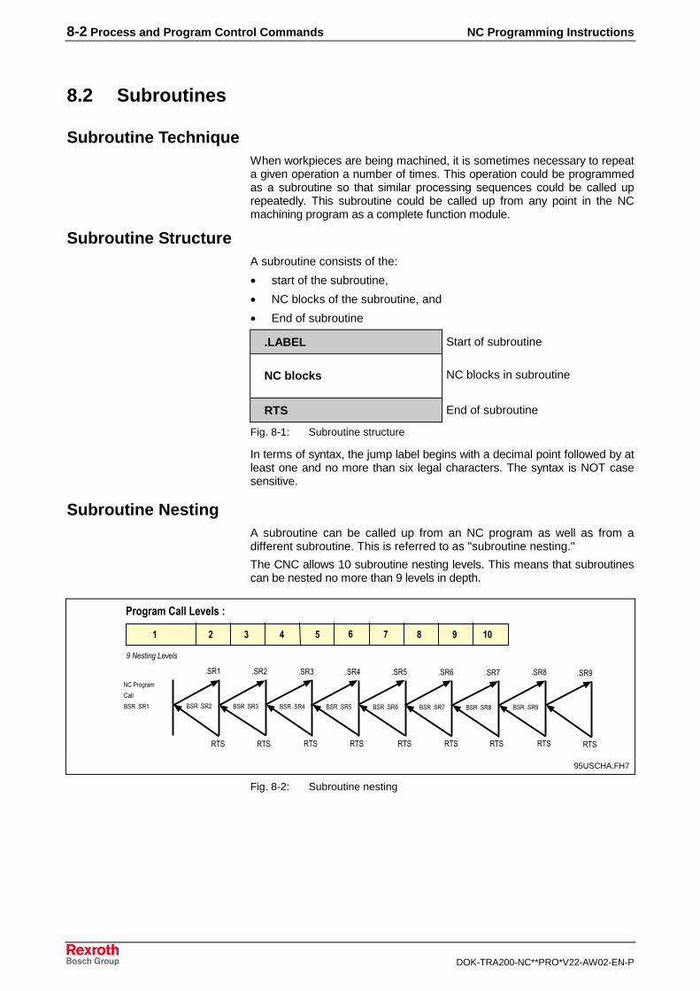
8-2 Process and Program Control Commands NC Programming Instructions
DOK-TRA200-NC**PRO*V22-AW02-EN-P
8.2 Subroutines
Subroutine TechniqueWhen workpieces are being machined, it is sometimes necessary to repeata given operation a number of times. This operation could be programmedas a subroutine so that similar processing sequences could be called uprepeatedly. This subroutine could be called up from any point in the NCmachining program as a complete function module.
Subroutine StructureA subroutine consists of the:
• start of the subroutine,
• NC blocks of the subroutine, and
• End of subroutine
.LABEL Start of subroutine
NC blocks NC blocks in subroutine
RTS End of subroutine
Fig. 8-1: Subroutine structure
In terms of syntax, the jump label begins with a decimal point followed by atleast one and no more than six legal characters. The syntax is NOT casesensitive.
Subroutine NestingA subroutine can be called up from an NC program as well as from adifferent subroutine. This is referred to as "subroutine nesting."
The CNC allows 10 subroutine nesting levels. This means that subroutinescan be nested no more than 9 levels in depth.
�������������� ��
���������
��� ���
����
��������������
��� ���
� � � � � � � � � ��
���
��� ���
���
��� ���
���
��� ���
���
��� ���
���
��� ���
���
��� ���
��� ��� ��� ���
���
��� ���
���
���
��� ���
���
���
���
���
����
��
95USCHA.FH7
Fig. 8-2: Subroutine nesting
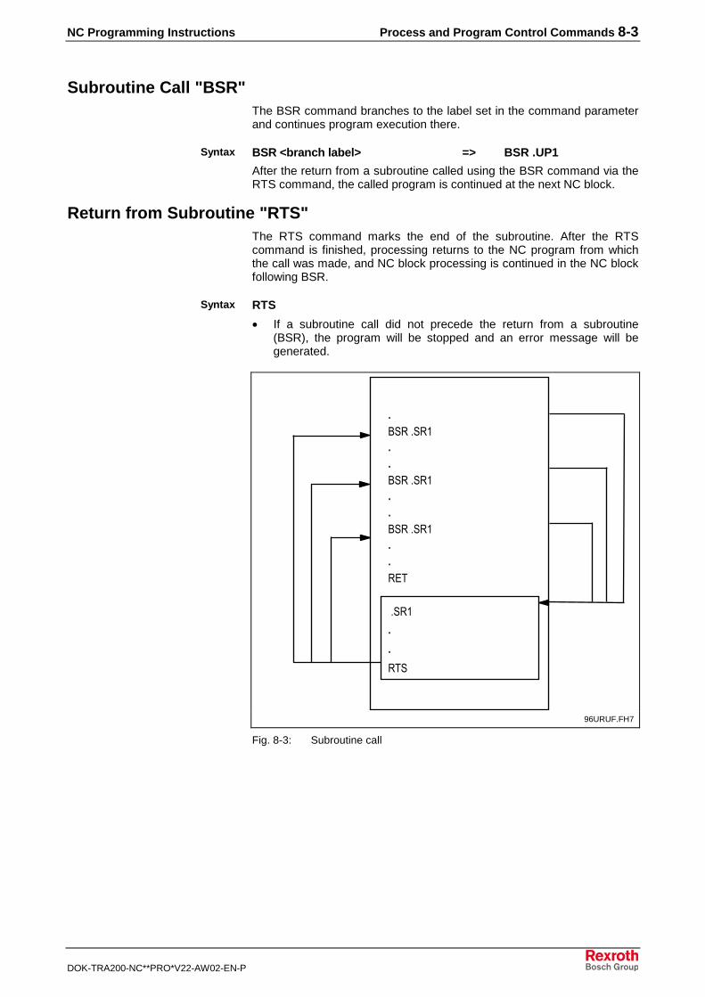
NC Programming Instructions Process and Program Control Commands 8-3
DOK-TRA200-NC**PRO*V22-AW02-EN-P
Subroutine Call "BSR"The BSR command branches to the label set in the command parameterand continues program execution there.
BSR <branch label> => BSR .UP1
After the return from a subroutine called using the BSR command via theRTS command, the called program is continued at the next NC block.
Return from Subroutine "RTS"The RTS command marks the end of the subroutine. After the RTScommand is finished, processing returns to the NC program from whichthe call was made, and NC block processing is continued in the NC blockfollowing BSR.
RTS
• If a subroutine call did not precede the return from a subroutine(BSR), the program will be stopped and an error message will begenerated.
���
��� ���
��� ���
��� ���
�
��
��
�����
� ���
�
�
����
�� ��
�
96URUF.FH7
Fig. 8-3: Subroutine call
Syntax
Syntax
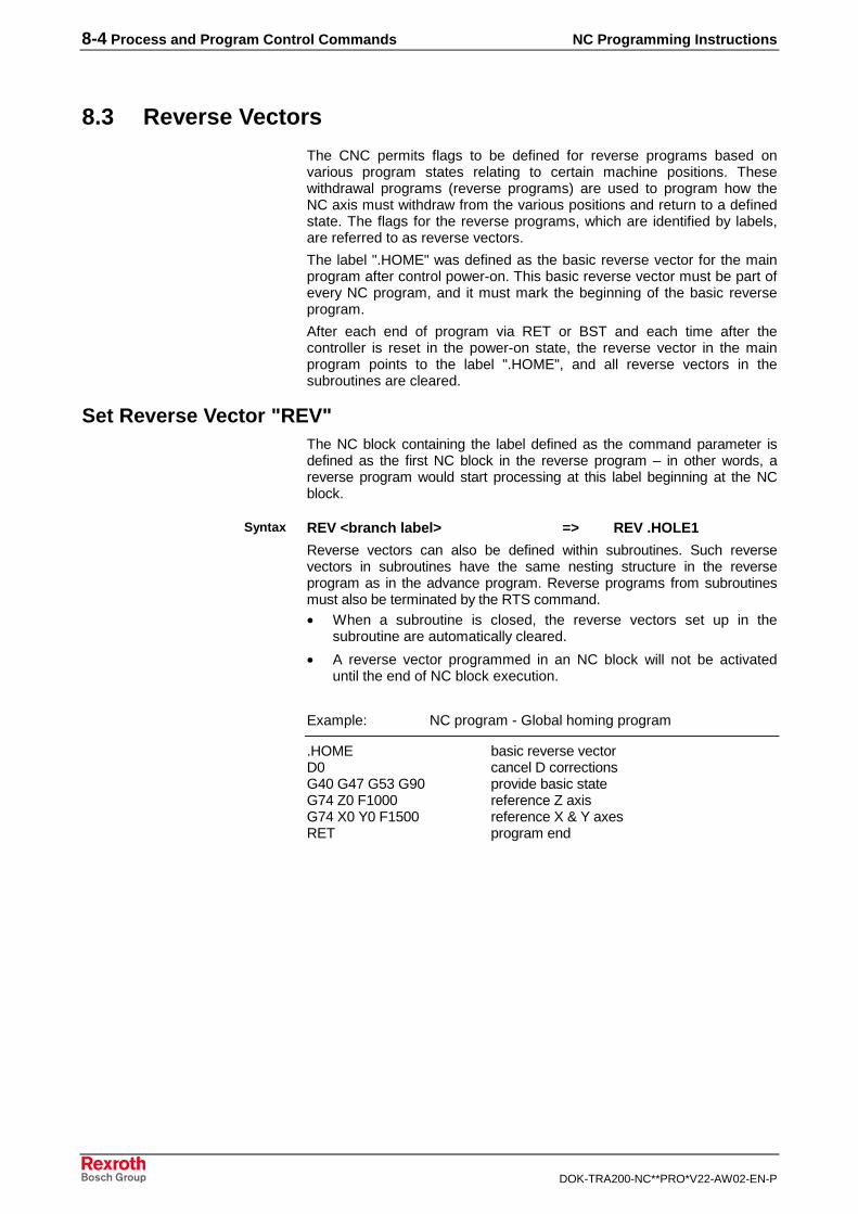
8-4 Process and Program Control Commands NC Programming Instructions
DOK-TRA200-NC**PRO*V22-AW02-EN-P
8.3 Reverse Vectors
The CNC permits flags to be defined for reverse programs based onvarious program states relating to certain machine positions. Thesewithdrawal programs (reverse programs) are used to program how theNC axis must withdraw from the various positions and return to a definedstate. The flags for the reverse programs, which are identified by labels,are referred to as reverse vectors.
The label ".HOME" was defined as the basic reverse vector for the mainprogram after control power-on. This basic reverse vector must be part ofevery NC program, and it must mark the beginning of the basic reverseprogram.
After each end of program via RET or BST and each time after thecontroller is reset in the power-on state, the reverse vector in the mainprogram points to the label ".HOME", and all reverse vectors in thesubroutines are cleared.
Set Reverse Vector "REV"The NC block containing the label defined as the command parameter isdefined as the first NC block in the reverse program – in other words, areverse program would start processing at this label beginning at the NCblock.
REV <branch label> => REV .HOLE1
Reverse vectors can also be defined within subroutines. Such reversevectors in subroutines have the same nesting structure in the reverseprogram as in the advance program. Reverse programs from subroutinesmust also be terminated by the RTS command.• When a subroutine is closed, the reverse vectors set up in the
subroutine are automatically cleared.
• A reverse vector programmed in an NC block will not be activateduntil the end of NC block execution.
Example: NC program - Global homing program
.HOME basic reverse vectorD0 cancel D correctionsG40 G47 G53 G90 provide basic stateG74 Z0 F1000 reference Z axisG74 X0 Y0 F1500 reference X & Y axesRET program end
Syntax
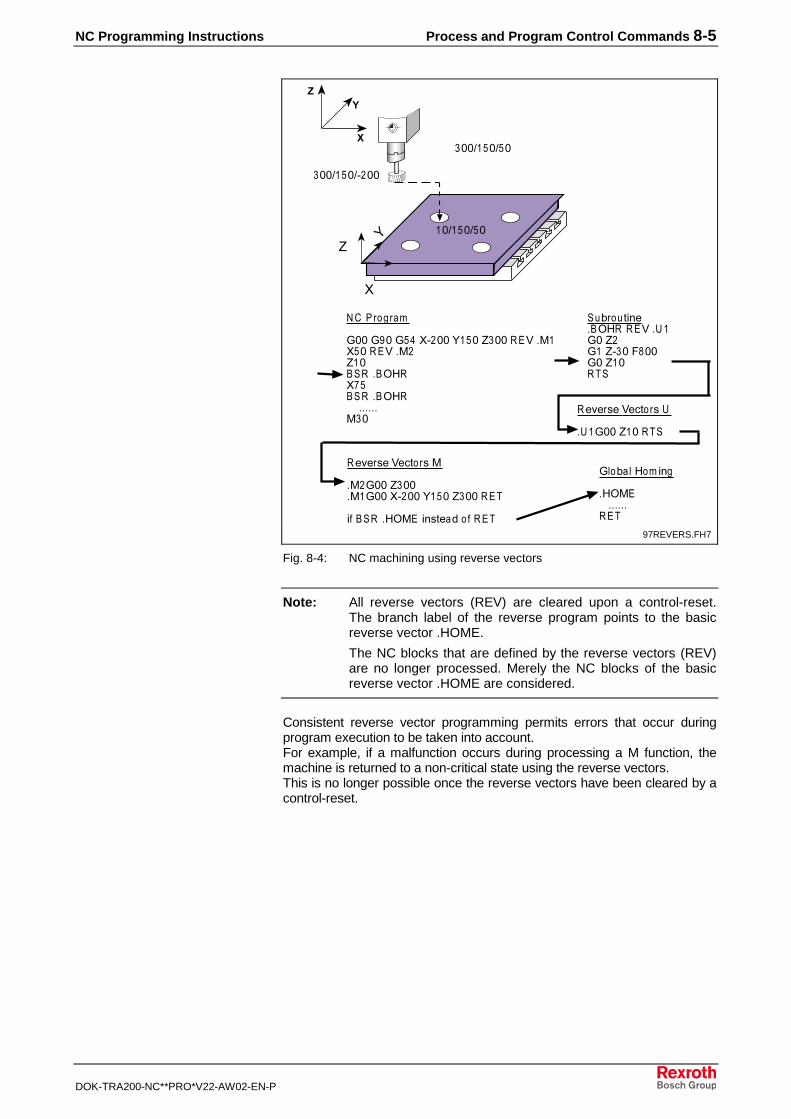
NC Programming Instructions Process and Program Control Commands 8-5
DOK-TRA200-NC**PRO*V22-AW02-EN-P
�������� ���
����������
���������
�� �� �����
!���!���!���" ����#����$������%� &�"�����%� &�$���� � '(�"���� � '(����� &��
��)���*+,- '(� ���%� ��!��$�!��$ ���.���!��$�����
�-/-�0-�%-1*��0��
��!���$������
�-/-�0-�%-1*��0�&
&�!���$��� &�!���" ����#����$�������
+���� � ('&��+,0*-�2�� �����
!��)� ��(� +,�
('&���� ���
���
-/-�
0 ��
�
#�
�
�
��
97REVERS.FH7
Fig. 8-4: NC machining using reverse vectors
Note: All reverse vectors (REV) are cleared upon a control-reset.The branch label of the reverse program points to the basicreverse vector .HOME.
The NC blocks that are defined by the reverse vectors (REV)are no longer processed. Merely the NC blocks of the basicreverse vector .HOME are considered.
Consistent reverse vector programming permits errors that occur duringprogram execution to be taken into account.For example, if a malfunction occurs during processing a M function, themachine is returned to a non-critical state using the reverse vectors.This is no longer possible once the reverse vectors have been cleared by acontrol-reset.
8-6 Process and Program Control Commands NC Programming Instructions
DOK-TRA200-NC**PRO*V22-AW02-EN-P
8.4 Conditional branches
Conditional branches are not performed unless the correspondingcondition is met. If this condition is not met, the program continuesexecution starting at the following NC block.
Branch for Reference "BRF"The BRF branch command can be used to determine whether the NCaxes in the CNC are located at their reference points.
BRF <branch label> => BRF .NORE
If the NC axes are properly referenced, program execution continues atthe branch label defined in the command parameter.
Branch if Event is Set "BES"The BES branch command is used to continue program processing at thedeclared branch label if the event defined in the command parameter is set.
BES <branch label> <event number[1-31]> => BES .LABEL 9
Branch if Event is Reset "BER"The BER branch command is used to continue program processing at thedeclared branch label if the event defined in the command parameter isreset.
BER <branch label> <event number[1-31]> => BER .LABEL 9
8.5 Branches Depending on Arithmetic Results
Branches which depend on arithmetic results relate to the results of themost recently performed arithmetic operation.
Branch if Result is Equal to Zero "BEQ"The branch command BEQ is used to continue program execution at thespecified branch label if the result of the most recent mathematicaloperation was equal to zero.
BEQ <branch label> => BEQ .ZERO
Branch if Result is not Equal to Zero "BNE"The branch command BNE is used to continue program execution at thespecified branch label if the result of the most recent mathematicaloperation was not equal to zero.
BNE <branch label> => BNE .NZERO
Branch if Result is Greater Than or Equal to Zero "BPL"The branch command BPL is used to continue program execution at thespecified label if the result of the most recent mathematical operation wasgreater than or equal to zero.
BPL <branch label> => BPL .GZERO
Syntax
Syntax
Syntax
Syntax
Syntax
Syntax
NC Programming Instructions Process and Program Control Commands 8-7
DOK-TRA200-NC**PRO*V22-AW02-EN-P
Branch if Result is Less Than Zero "BMI"The branch command BMI is used to continue program execution at thespecified branch label if the result of the most recent mathematicaloperation was less than zero.
BMI <branch label> => BMI .LZERO
Overview Table@10=A-B @10=B-A
A = B BEQ BEQ
A <> B BNE BNE
A < B BMI ---
A <= B --- BPL
A > B --- BMI
A >= B BPL ---
Note: Due to resolution inaccuracies, there can be malfunctions ormissing functions when BEQ or BNE is used if the arithmeticresults are decimal fractions.
WARNING
Incorrect program jumps may lead to damage toworkpiece and/or machine.
Example:
@10 = 51.8 -50-1.8 BEQ .label (result=0)does not function!
Recovery:Depending on the resolution, e.g. 0.01, convert into an integer expression:@100=INT((51.8-50-1.8)•1000) BEQ .label functions!
Example: NC program Loop construction
@51=0 preassign the loop variables.NEXT loop starting label@51=@51+1 increment loop variable@10=DCD(,1,@51) read D correction 1
element=@51@10=@10-25 BEQ .BREAK if D correction 1
element=25, then leave loop@10=@51-4 BMI .NEXT query loop variable whether loop
condition is still fulfilled[no element of D correction 1has value 25] issue messageHLT acknowledge programmed stop
from PLC
BRA .EXIT jump to end of program.BREAK loop exit label
Syntax

8-8 Process and Program Control Commands NC Programming Instructions
DOK-TRA200-NC**PRO*V22-AW02-EN-P
[one element of D correction 1has value 25] issue messageHLT acknowledge programmed halt
from PLC.EXIT program end labelRET
NC Programming Instructions Variable Assignments and Arithmetic Functions 9-1
DOK-TRA200-NC**PRO*V22-AW02-EN-P
9 Variable Assignments and Arithmetic Functions
9.1 Variables
NC variables are used in an NC program to represent a numerical value.A value can be assigned to an NC variable by the NC program, PLC pro-gram or from the user interface; the value of the NC variable can be readaccordingly by these programs or by the user interface.
NC variables are identified• by the address @
• by a 1-2-digit number
A total of 80 NC variables are available in the CNC (0- 79).
@<Variable number[0..79]> => @30
@<Variable number[0..79]>
=<mathematical expression> => @10=5*100
Note: The internal data representation of a value employs the"Double Real" format. The values for entry range from -1.0E±300 to +1.0E±300. Only values with a maximum of 7 digitscan be programmed in the NC program ("Single Real" format).
.123456789123456
123456789123456
15E+20
90E-10
If the content of an NC variable is to be negated, the NC variable must beplaced within parentheses.
X=-(@20)
@12=-(@19)
-(@57)=@58
@23=X
Note: Regardless of the display mode (workpiece or machinecoordinate system), machine coordinates are always outputwhen axis values are read.
Syntax
Syntax for assigning a value to avariable
Syntax for presenting the data
Syntax for negating the contentsof a variable
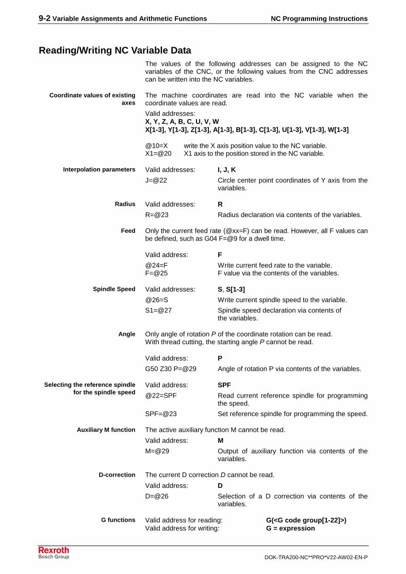
9-2 Variable Assignments and Arithmetic Functions NC Programming Instructions
DOK-TRA200-NC**PRO*V22-AW02-EN-P
Reading/Writing NC Variable DataThe values of the following addresses can be assigned to the NCvariables of the CNC, or the following values from the CNC addressescan be written into the NC variables.
The machine coordinates are read into the NC variable when thecoordinate values are read.
Valid addresses:X, Y, Z, A, B, C, U, V, WX[1-3], Y[1-3], Z[1-3], A[1-3], B[1-3], C[1-3], U[1-3], V[1-3], W[1-3]
@10=X write the X axis position value to the NC variable.X1=@20 X1 axis to the position stored in the NC variable.
Valid addresses: I, J, K
J=@22 Circle center point coordinates of Y axis from thevariables.
Valid addresses: R
R=@23 Radius declaration via contents of the variables.
Only the current feed rate (@xx=F) can be read. However, all F values canbe defined, such as G04 F=@9 for a dwell time.
Valid address: F
@24=F Write current feed rate to the variable.F=@25 F value via the contents of the variables.
Valid addresses: S, S[1-3]
@26=S Write current spindle speed to the variable.
S1=@27 Spindle speed declaration via contents of the variables.
Only angle of rotation P of the coordinate rotation can be read.With thread cutting, the starting angle P cannot be read.
Valid address: P
G50 Z30 P=@29 Angle of rotation P via contents of the variables.
Valid address: SPF
@22=SPF Read current reference spindle for programmingthe speed.
SPF=@23 Set reference spindle for programming the speed.
The active auxiliary function M cannot be read.
Valid address: M
M=@29 Output of auxiliary function via contents of thevariables.
The current D correction D cannot be read.
Valid address: D
D=@26 Selection of a D correction via contents of thevariables.
Valid address for reading: G(<G code group[1-22]>)Valid address for writing: G = expression
Coordinate values of existingaxes
Interpolation parameters
Radius
Feed
Spindle Speed
Angle
Selecting the reference spindlefor the spindle speed
Auxiliary M function
D-correction
G functions
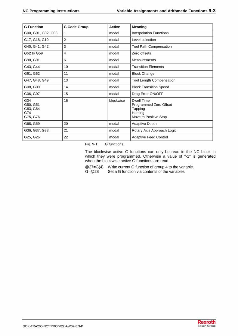
NC Programming Instructions Variable Assignments and Arithmetic Functions 9-3
DOK-TRA200-NC**PRO*V22-AW02-EN-P
G Function G Code Group Active Meaning
G00, G01, G02, G03 1 modal Interpolation Functions
G17, G18, G19 2 modal Level selection
G40, G41, G42 3 modal Tool Path Compensation
G52 to G59 4 modal Zero offsets
G90, G91 6 modal Measurements
G43, G44 10 modal Transition Elements
G61, G62 11 modal Block Change
G47, G48, G49 13 modal Tool Length Compensation
G08, G09 14 modal Block Transition Speed
G06, G07 15 modal Drag Error ON/OFF
G04G50, G51G63, G64G74G75, G76
16 blockwise Dwell TimeProgrammed Zero OffsetTappingHomingMove to Positive Stop
G68, G69 20 modal Adaptive Depth
G36, G37, G38 21 modal Rotary Axis Approach Logic
G25, G26 22 modal Adaptive Feed Control
Fig. 9-1: G functions
The blockwise active G functions can only be read in the NC block inwhich they were programmed. Otherwise a value of "-1" is generatedwhen the blockwise active G functions are read.
@27=G(4) Write current G function of group 4 to the variable.G=@28 Set a G function via contents of the variables.
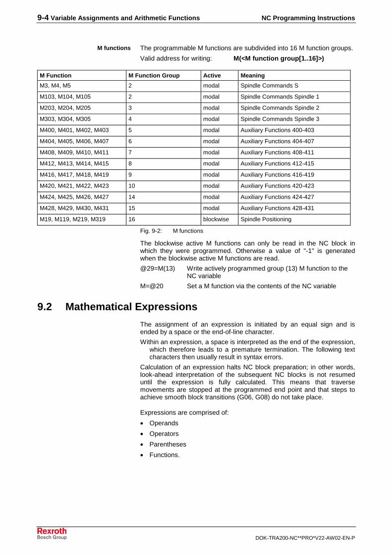
9-4 Variable Assignments and Arithmetic Functions NC Programming Instructions
DOK-TRA200-NC**PRO*V22-AW02-EN-P
The programmable M functions are subdivided into 16 M function groups.
Valid address for writing: M(<M function group[1..16]>)
M Function M Function Group Active Meaning
M3, M4, M5 2 modal Spindle Commands S
M103, M104, M105 2 modal Spindle Commands Spindle 1
M203, M204, M205 3 modal Spindle Commands Spindle 2
M303, M304, M305 4 modal Spindle Commands Spindle 3
M400, M401, M402, M403 5 modal Auxiliary Functions 400-403
M404, M405, M406, M407 6 modal Auxiliary Functions 404-407
M408, M409, M410, M411 7 modal Auxiliary Functions 408-411
M412, M413, M414, M415 8 modal Auxiliary Functions 412-415
M416, M417, M418, M419 9 modal Auxiliary Functions 416-419
M420, M421, M422, M423 10 modal Auxiliary Functions 420-423
M424, M425, M426, M427 14 modal Auxiliary Functions 424-427
M428, M429, M430, M431 15 modal Auxiliary Functions 428-431
M19, M119, M219, M319 16 blockwise Spindle Positioning
Fig. 9-2: M functions
The blockwise active M functions can only be read in the NC block inwhich they were programmed. Otherwise a value of "-1" is generatedwhen the blockwise active M functions are read.
@29=M(13) Write actively programmed group (13) M function to theNC variable
M=@20 Set a M function via the contents of the NC variable
9.2 Mathematical Expressions
The assignment of an expression is initiated by an equal sign and isended by a space or the end-of-line character.
Within an expression, a space is interpreted as the end of the expression,which therefore leads to a premature termination. The following textcharacters then usually result in syntax errors.
Calculation of an expression halts NC block preparation; in other words,look-ahead interpretation of the subsequent NC blocks is not resumeduntil the expression is fully calculated. This means that traversemovements are stopped at the programmed end point and that steps toachieve smooth block transitions (G06, G08) do not take place.
Expressions are comprised of:
• Operands
• Operators
• Parentheses
• Functions.
M functions
NC Programming Instructions Variable Assignments and Arithmetic Functions 9-5
DOK-TRA200-NC**PRO*V22-AW02-EN-P
Examples: expressions
@200=X+SQRT(2)*SQRT(X*X+Z*Z)F=0.1*PI*800@201=TAN(@200)@202=SQRT(@200)+F@203=@205+@206/@207-50
@20=X+ABS(@1)*INT(@2+@3*100)F=0.1*PI*800@23=@25+@26/@27-50
OperandsOperands can be:• constants,
• system constants,
• variables,
• address letters, and
• functions.
Floating decimal point constants can be comprised of the followingelements:
• sign of the mantissa,
• up to 6 decimal digits,
• decimal point behind the first through sixth decimal digits,
• exponent symbol E,
• sign of the exponent, and
• up to 2 decimal digits for the exponent.
In order for internal floating decimal point calculations to be used, thedecimal point or the exponent sign must be present.
Example: valid floating decimal point constants
-0.+123456.1E0-123456E+10.1E-00+100.000E12
The numerical decimal value statement is interpreted as an integerconstant, both without the decimal point and without the exponent. Integerconstants can optionally consist of a sign and up to ten decimal places.
Example: valid whole-number constants
-01+1234567890
The circle number "PI" (3.14159265...) and the conversion factor from theinch system to the metric "KI" system (25.4) are available for use assystem constants which are programmed using their symbolic names.Because of their higher internal accuracy, these constants should alwaysbe used.
Constants
System constants
9-6 Variable Assignments and Arithmetic Functions NC Programming Instructions
DOK-TRA200-NC**PRO*V22-AW02-EN-P
OperatorsThe standard symbols for basic mathematical operations can be used asoperators.
+ Addition
− Subtraction
∗ Multiplication
/ Division
% Remainder of an integer division (modulo)
• Division by 0 will cause an error.
• Higher-order operations are implemented by functions.
ParenthesesTo nest expressions and circumvent the integrated principle"multiplication/division before addition/subtraction", partial expressions canbe placed within parentheses. The number of nesting levels is unlimited.
FunctionsThe CNC provides the following mathematical functions:
ABS absolute value
INT integer
E^ power to base "e"
10^ power to base 10
2^ power to base 2
TIME time in seconds
The mathematical functions enclose their operands in parentheses. Theoperands used in functions can also be expressions – in other words, thefunctions can be nested.
The absolute value function delivers the positive value of its operand.
x < 0: ABS(x) = x
x = 0: ABS(x) = 0
x > 0: ABS(x) = x
Example:
ABS(-1.23) => 1.23
The "INT" function delivers the next smallest whole number for theoperand.
Example:
INT(1.99) => 1INT(1.01) => 1INT(-2.99) => -2INT(-2.01) => -2
Example:
E^(-2.5) => 0.082...
Example:
10^(3) => 1000
Sum - ABS
Integer component - INT
Power to base - E^
Power to base - 10 10^
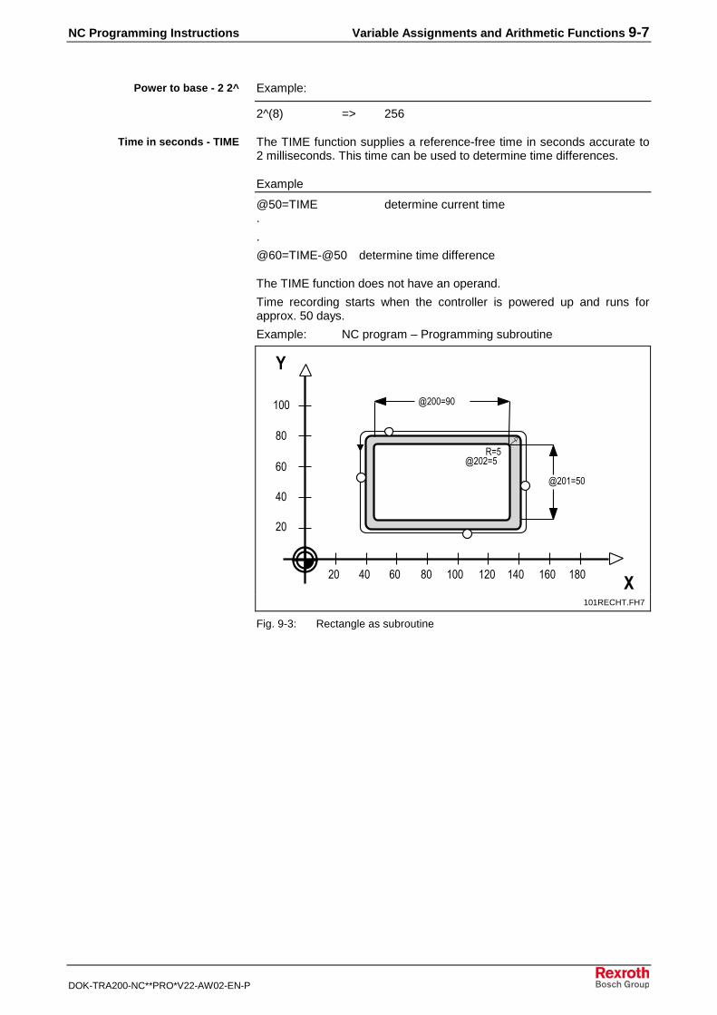
NC Programming Instructions Variable Assignments and Arithmetic Functions 9-7
DOK-TRA200-NC**PRO*V22-AW02-EN-P
Example:
2^(8) => 256
The TIME function supplies a reference-free time in seconds accurate to2 milliseconds. This time can be used to determine time differences.
Example
@50=TIME determine current time.
.
@60=TIME-@50 determine time difference
The TIME function does not have an operand.
Time recording starts when the controller is powered up and runs forapprox. 50 days.
Example: NC program – Programming subroutine
��
��
��
��
���
�� �� �� �� ��� �
�
��� ��� ��� ���
������
������
�������
����
� ��
����
101RECHT.FH7
Fig. 9-3: Rectangle as subroutine
Power to base - 2 2^
Time in seconds - TIME
9-8 Variable Assignments and Arithmetic Functions NC Programming Instructions
DOK-TRA200-NC**PRO*V22-AW02-EN-P
NC program:G00 G54 G06 G08 X160 Y80 Z10 start positionG01 Z-10 F1000 feed Z axisG42 X135 Y80 F1500 establish tool path
compensation@20=90 @21=50 @22=5 @23=1200 preassign variablesBSR .RE1 call subroutineG90 G00 Z10 Z axis to safety distanceG40 G01 X160 Y110 remove tool path
compensationRET program end
.RE1 rectangle subroutineG01 G91 F=@23 set incr. data input, feedX=-(@20) 1st
straight line in XG03 X=-(@22) Y=-(@22) J=-(@22) 1st
¼ circleG01 Y=-(@21) 1st
straight line in YG03 X=@22 Y=-(@22) I=@22 2nd
¼ circleG01 X=@20 2nd
straight line in XG03 X=@22 Y=@22 J=@22 3rd
¼ circleG01 Y=@21 2nd
straight line in YG03 X=-(@22) Y=@22 I=-(@22) 4th
¼ circleG01 X=-(@21/50) clear X axisY=@21/10 clear Y axisRTS subroutine end
NC Programming Instructions Special NC Functions 10-1
DOK-TRA200-NC**PRO*V22-AW02-EN-P
10 Special NC Functions
10.1 APR SERCOS Parameters
Data Exchange with Digital Drives "AXD"The "AXD" command can be used to read or write the drive data from orto the NC program for a digital drive which is connected to the CNC bymeans of a digital SERCOS interface. The drive datum which is to beread or written is addressed using the data address defined in thecommand parameter.
AXD(<axis name>:<SERCOS ID number>
AXD(<axis number>:<SERCOS ID number>
The letters X, Y, Z, U, V, W, A, B, C and optionally S with the enhancedaddress structure [1-3] can be used as the axis name. The axis number[1.0.7] can be specified alternatively. It is essential that these axes also beparameterized and that they be digital drives which are connected via theSERCOS Interface.
<group letter>-<parameter set number>-<data block number>
The group letter differentiates between:• standard data (S),
defined by the SERCOS standards committee, and
• product data (P),defined by the drive manufacturer.
The minus sign (-) is used as a delimiter character between the individualparameters.The parameter set number addresses the desired parameter set. Theparameter set number can have values from 0 to 7.The pertaining drive datum can be addressed via the data block number.The data block number can range from 0 (also 0000) to 4095.The meaning of the SERCOS parameters (group letter S) and theirfunctions are described by the SERCOS committee in the publication"SERCOS Interface."The meaning of the SERCOS parameters (group letter P) and theirfunctions are described in the documentation for the SERCOS digital drive.• The reading or writing of drive data using the "AXD command" should
be programmed in a separate NC block which does not contain anyother NC commands.
• The reading or writing of drive data using the "AXD command" alwaystakes place at the end of the NC block. In other words, theassignment of a value to an NC variable into which the drive datumwas read cannot be used in the same NC block as the basis fordeciding whether a conditional branch/jump is to be performed.
• When drive data is read or written using the "AXD" command, NCblock preprocessing is interrupted. Thus if tool path compensation(G41, G42) is active, it is considered to be finished. Likewise,"contouring mode (acceleration)" (G08) is no longer possible.
Syntax
SERCOS ID number
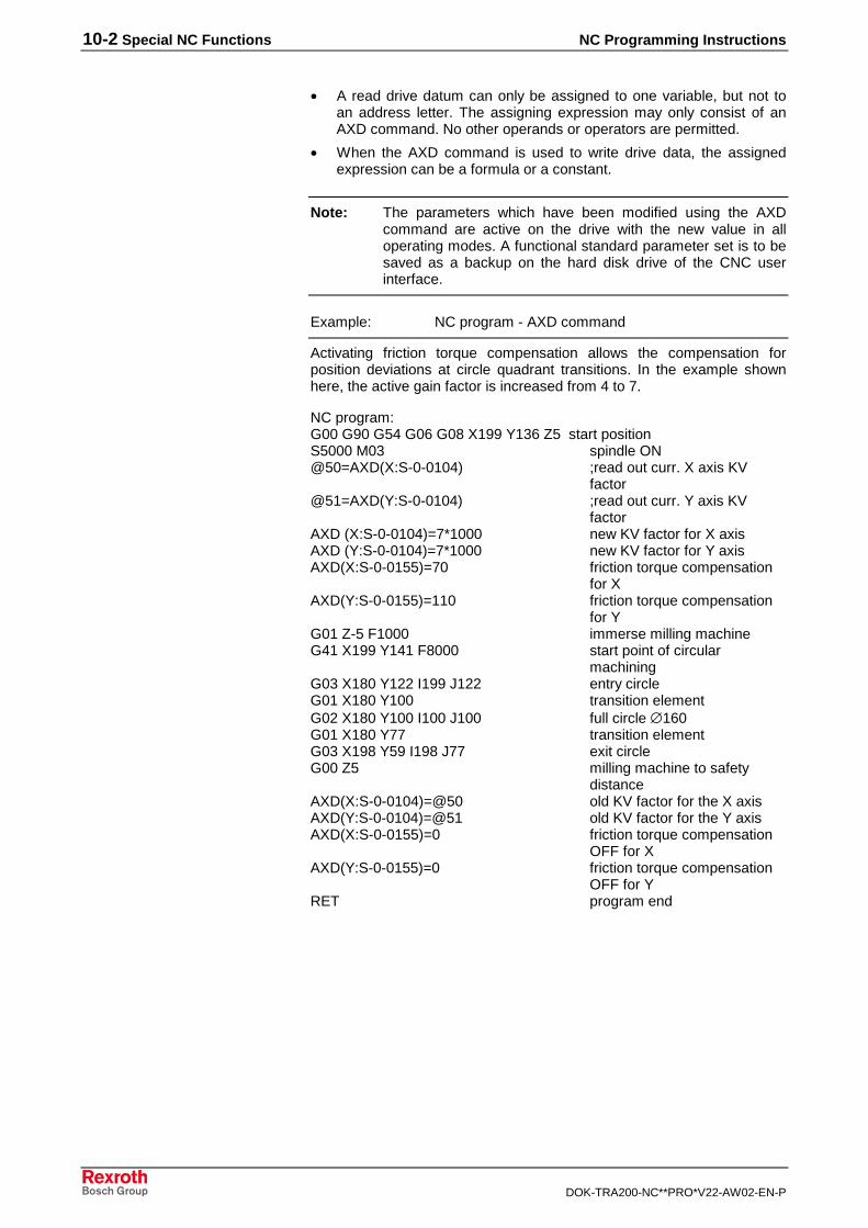
10-2 Special NC Functions NC Programming Instructions
DOK-TRA200-NC**PRO*V22-AW02-EN-P
• A read drive datum can only be assigned to one variable, but not toan address letter. The assigning expression may only consist of anAXD command. No other operands or operators are permitted.
• When the AXD command is used to write drive data, the assignedexpression can be a formula or a constant.
Note: The parameters which have been modified using the AXDcommand are active on the drive with the new value in alloperating modes. A functional standard parameter set is to besaved as a backup on the hard disk drive of the CNC userinterface.
Example: NC program - AXD command
Activating friction torque compensation allows the compensation forposition deviations at circle quadrant transitions. In the example shownhere, the active gain factor is increased from 4 to 7.
NC program:G00 G90 G54 G06 G08 X199 Y136 Z5 start positionS5000 M03 spindle ON@50=AXD(X:S-0-0104) ;read out curr. X axis KV
factor@51=AXD(Y:S-0-0104) ;read out curr. Y axis KV
factorAXD (X:S-0-0104)=7*1000 new KV factor for X axisAXD (Y:S-0-0104)=7*1000 new KV factor for Y axisAXD(X:S-0-0155)=70 friction torque compensation
for XAXD(Y:S-0-0155)=110 friction torque compensation
for YG01 Z-5 F1000 immerse milling machineG41 X199 Y141 F8000 start point of circular
machiningG03 X180 Y122 I199 J122 entry circleG01 X180 Y100 transition elementG02 X180 Y100 I100 J100 full circle ∅160G01 X180 Y77 transition elementG03 X198 Y59 I198 J77 exit circleG00 Z5 milling machine to safety
distanceAXD(X:S-0-0104)=@50 old KV factor for the X axisAXD(Y:S-0-0104)=@51 old KV factor for the Y axisAXD(X:S-0-0155)=0 friction torque compensation
OFF for XAXD(Y:S-0-0155)=0 friction torque compensation
OFF for YRET program end
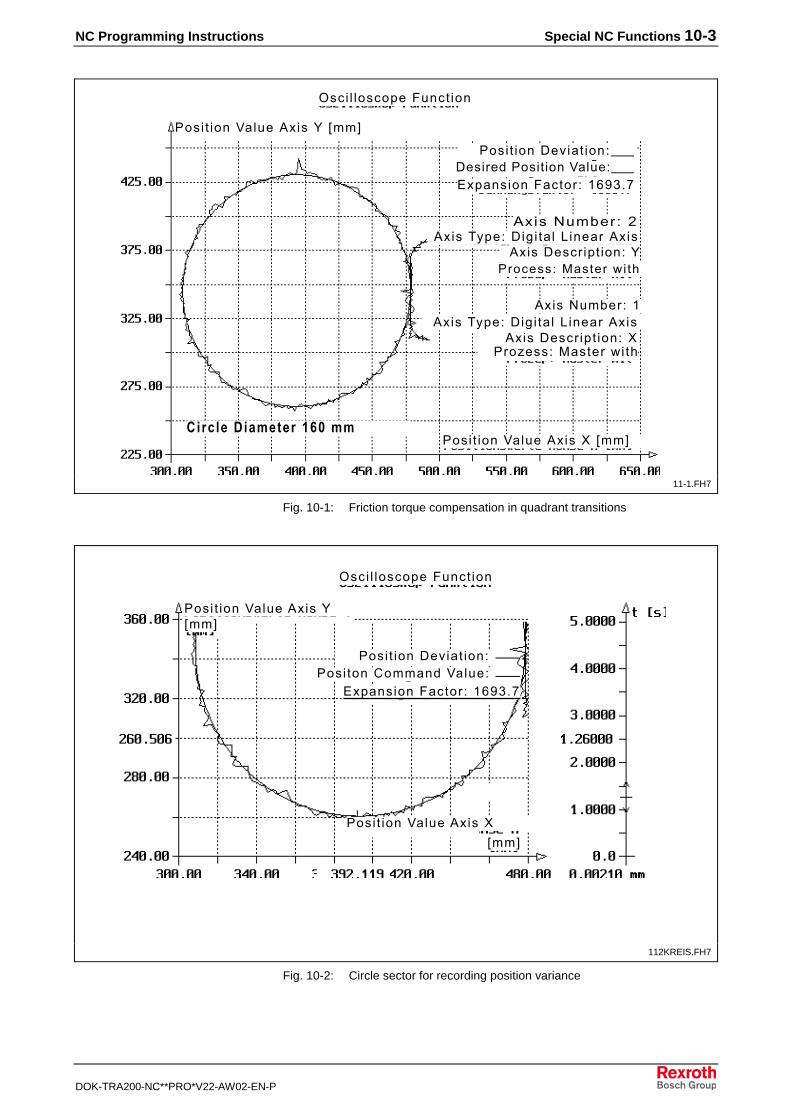
NC Programming Instructions Special NC Functions 10-3
DOK-TRA200-NC**PRO*V22-AW02-EN-P
����
������ ���� � ���������� ���
���� �������� ���� ����������� ����
����������� ��� ������
���� ������������� !!"
��������� �� ���� # ���$����%�� ��&� '
����(�!)��� �
����������� ����� ��������%�� ��&� '
����*+�����,� � � - �������������(�!)��� .
���� ������������# !!"���� �� ������� �� � �
����������� ��������������� ���������
��������%�� ��&� ' ��������%�� ��&� ' ��������%�� ��&� ' ��������%�� ��&� ' ��������%�� ��&� '
����*+�����,� � � - ���������
����������� �������������%�� ��&� '
���$����%�� ��&� '
���� �������� ��������������� ���������
11-1.FH7
Fig. 10-1: Friction torque compensation in quadrant transitions
���� � ���������� ���
!!"
!!"
���� �������� ���� ���� ��/�!!���������
����������� ��� ������
���� �������������
���� ������������#
112KREIS.FH7
Fig. 10-2: Circle sector for recording position variance
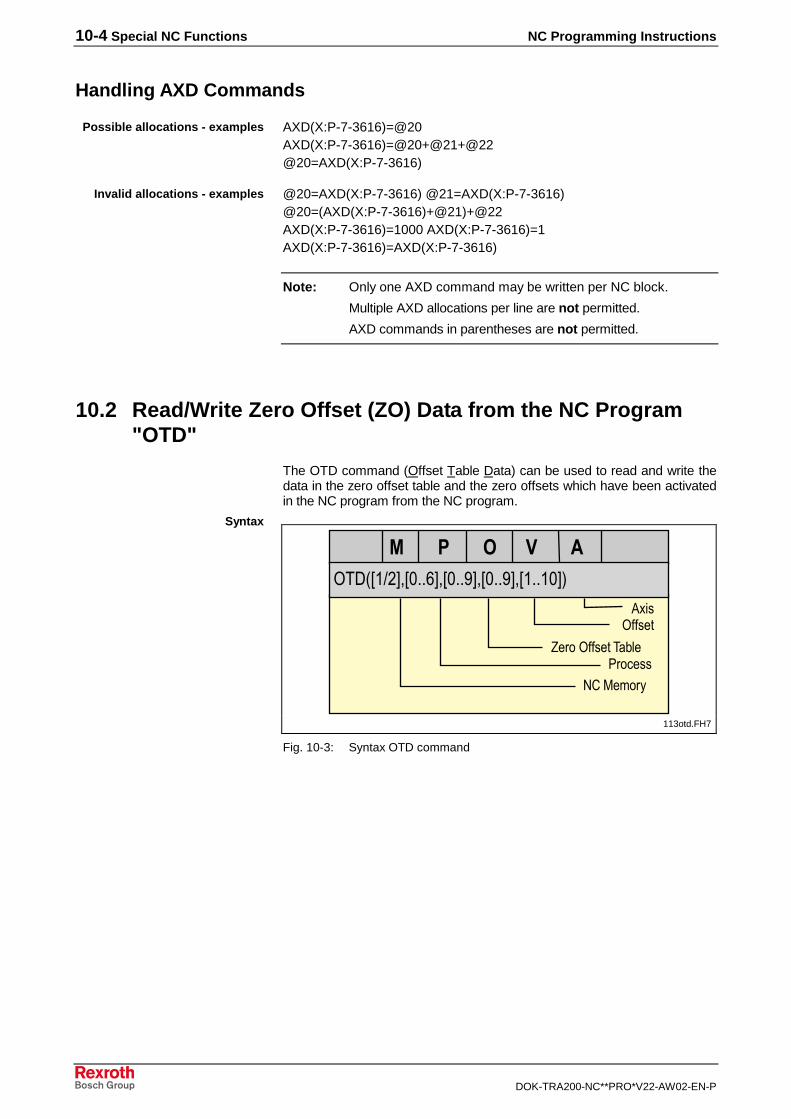
10-4 Special NC Functions NC Programming Instructions
DOK-TRA200-NC**PRO*V22-AW02-EN-P
Handling AXD Commands
AXD(X:P-7-3616)=@20AXD(X:P-7-3616)=@20+@21+@22@20=AXD(X:P-7-3616)
@20=AXD(X:P-7-3616) @21=AXD(X:P-7-3616)@20=(AXD(X:P-7-3616)+@21)+@22AXD(X:P-7-3616)=1000 AXD(X:P-7-3616)=1AXD(X:P-7-3616)=AXD(X:P-7-3616)
Note: Only one AXD command may be written per NC block.
Multiple AXD allocations per line are not permitted.
AXD commands in parentheses are not permitted.
10.2 Read/Write Zero Offset (ZO) Data from the NC Program"OTD"
The OTD command (Offset Table Data) can be used to read and write thedata in the zero offset table and the zero offsets which have been activatedin the NC program from the NC program.
� �������������������������������������
���������������������������������
��������
���������� � !�"��#���
$%�&�'��(
113otd.FH7
Fig. 10-3: Syntax OTD command
Possible allocations - examples
Invalid allocations - examples
Syntax

NC Programming Instructions Special NC Functions 10-5
DOK-TRA200-NC**PRO*V22-AW02-EN-P
Designation Symb. Declarationrange
CNC Meaning
NC memory(optional)
M 1 / 2 MTC200 1: NC memory A or 2: NC memory BIf the parameter is not declared, the current NC memory isaddressed.
Process(optional)
P 0..6 MTC200 If no process number is specified, the current process isaddressed.
Zero offsettable(optional)
O 0..9 MTC200 If the parameter is not declared, the active zero offset tableis addressed.
Offset(optional)
V 0..9 MTC200TRANS200
0 = active offset 1 = value of G50/G51 offset 2 = value of G52 offset 3 = general offset 4 = G54 value 5 = G55 value 6 = G56 value 7 = G57 value 8 = G58 value 9 = G59 valueIf no parameter is specified, the current offset (0) isaddressed.
axis A 1..10 MTC200TRANS200
1 = value of X axis 2 = value of Y axis 3 = value of Z axis 4 = value of U axis 5 = value of V axis 6 = value of W axis 7 = value of A axis 8 = value of B axis 9 = value of C axis10 = value of twisting angleThe axis parameter must be specified.The axis letter correlates with the axis meaning!
A variable can be inserted instead of the constant.
• An arithmetic expression instead of a constant or variable is notpermitted.
• The optional parameters need not be specified.
• The commas that are used for delimiting the parameters must alwaysbe set.
The command OTD can not be used for writing to the zero offset valuesfor G50/G51, G52 and to the active zero offset value.
Example: NC program - Reading ZO data
@20=OTD(,,,,1) read active X axis zero offset.X=OTD (,,,4,1) traverse X axis to the position which is
located in the ZO table for G54
.
@70=G(4) read G function of zero offset@70=@70-50 prepare value for the OTD command.@20=OTD(,,,@70,1) read active X axis zero offset for the ZO
entry corresponding to the active Gfunction (G52- G59)
General requirements for theOTD command
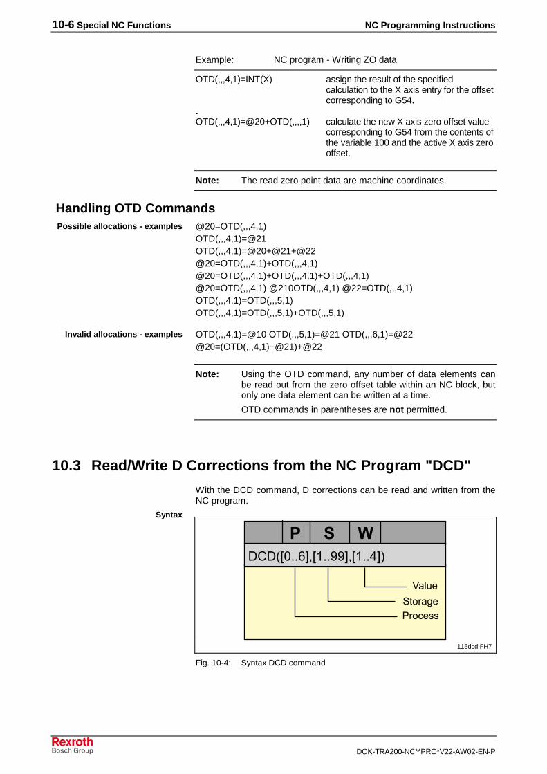
10-6 Special NC Functions NC Programming Instructions
DOK-TRA200-NC**PRO*V22-AW02-EN-P
Example: NC program - Writing ZO data
OTD(,,,4,1)=INT(X) assign the result of the specifiedcalculation to the X axis entry for the offsetcorresponding to G54.
.OTD(,,,4,1)=@20+OTD(,,,,1) calculate the new X axis zero offset value
corresponding to G54 from the contents ofthe variable 100 and the active X axis zerooffset.
Note: The read zero point data are machine coordinates.
Handling OTD Commands@20=OTD(,,,4,1)OTD(,,,4,1)=@21OTD(,,,4,1)=@20+@21+@22@20=OTD(,,,4,1)+OTD(,,,4,1)@20=OTD(,,,4,1)+OTD(,,,4,1)+OTD(,,,4,1)@20=OTD(,,,4,1) @210OTD(,,,4,1) @22=OTD(,,,4,1)OTD(,,,4,1)=OTD(,,,5,1)OTD(,,,4,1)=OTD(,,,5,1)+OTD(,,,5,1)
OTD(,,,4,1)=@10 OTD(,,,5,1)=@21 OTD(,,,6,1)=@22@20=(OTD(,,,4,1)+@21)+@22
Note: Using the OTD command, any number of data elements canbe read out from the zero offset table within an NC block, butonly one data element can be written at a time.
OTD commands in parentheses are not permitted.
10.3 Read/Write D Corrections from the NC Program "DCD"
With the DCD command, D corrections can be read and written from theNC program.
�/�0 1���"2 �����"2 ���3"4
���������������
�����
5 ���,��������
115dcd.FH7
Fig. 10-4: Syntax DCD command
Possible allocations - examples
Invalid allocations - examples
Syntax
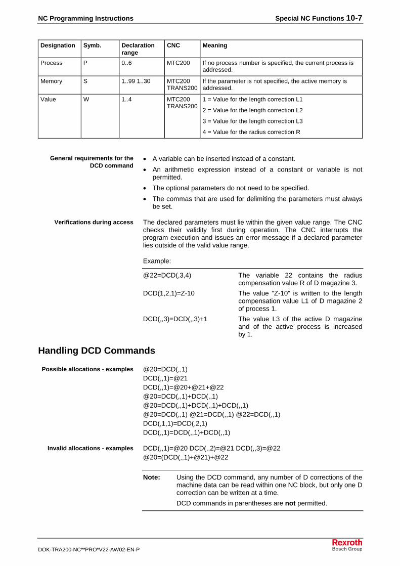
NC Programming Instructions Special NC Functions 10-7
DOK-TRA200-NC**PRO*V22-AW02-EN-P
Designation Symb. Declarationrange
CNC Meaning
Process P 0..6 MTC200 If no process number is specified, the current process isaddressed.
Memory S 1..99 1..30 MTC200TRANS200
If the parameter is not specified, the active memory isaddressed.
Value W 1..4 MTC200TRANS200
1 = Value for the length correction L1
2 = Value for the length correction L2
3 = Value for the length correction L3
4 = Value for the radius correction R
• A variable can be inserted instead of a constant.
• An arithmetic expression instead of a constant or variable is notpermitted.
• The optional parameters do not need to be specified.
• The commas that are used for delimiting the parameters must alwaysbe set.
The declared parameters must lie within the given value range. The CNCchecks their validity first during operation. The CNC interrupts theprogram execution and issues an error message if a declared parameterlies outside of the valid value range.
Example:
@22=DCD(,3,4) The variable 22 contains the radiuscompensation value R of D magazine 3.
DCD(1,2,1)=Z-10 The value "Z-10" is written to the lengthcompensation value L1 of D magazine 2of process 1.
DCD(,,3)=DCD(,,3)+1 The value L3 of the active D magazineand of the active process is increasedby 1.
Handling DCD Commands
@20=DCD(,,1)DCD(,,1)=@21DCD(,,1)=@20+@21+@22@20=DCD(,,1)+DCD(,,1)@20=DCD(,,1)+DCD(,,1)+DCD(,,1)@20=DCD(,,1) @21=DCD(,,1) @22=DCD(,,1)DCD(,1,1)=DCD(,2,1)DCD(,,1)=DCD(,,1)+DCD(,,1)
DCD(,,1)=@20 DCD(,,2)=@21 DCD(,,3)=@22@20=(DCD(,,1)+@21)+@22
Note: Using the DCD command, any number of D corrections of themachine data can be read within one NC block, but only one Dcorrection can be written at a time.
DCD commands in parentheses are not permitted.
General requirements for theDCD command
Verifications during access
Possible allocations - examples
Invalid allocations - examples
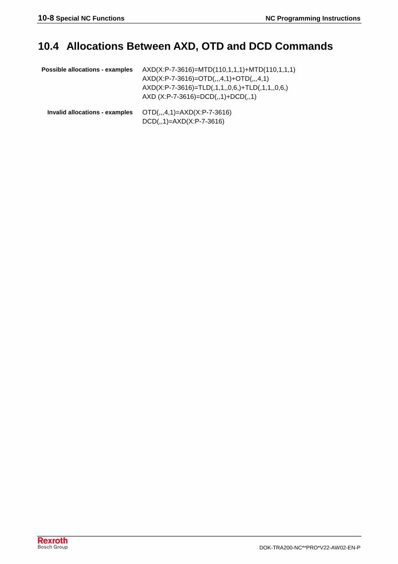
10-8 Special NC Functions NC Programming Instructions
DOK-TRA200-NC**PRO*V22-AW02-EN-P
10.4 Allocations Between AXD, OTD and DCD Commands
AXD(X:P-7-3616)=MTD(110,1,1,1)+MTD(110,1,1,1)AXD(X:P-7-3616)=OTD(,,,4,1)+OTD(,,,4,1)AXD(X:P-7-3616)=TLD(,1,1,,0,6,)+TLD(,1,1,,0,6,)AXD (X:P-7-3616)=DCD(,,1)+DCD(,,1)
OTD(,,,4,1)=AXD(X:P-7-3616)DCD(,,1)=AXD(X:P-7-3616)
Possible allocations - examples
Invalid allocations - examples
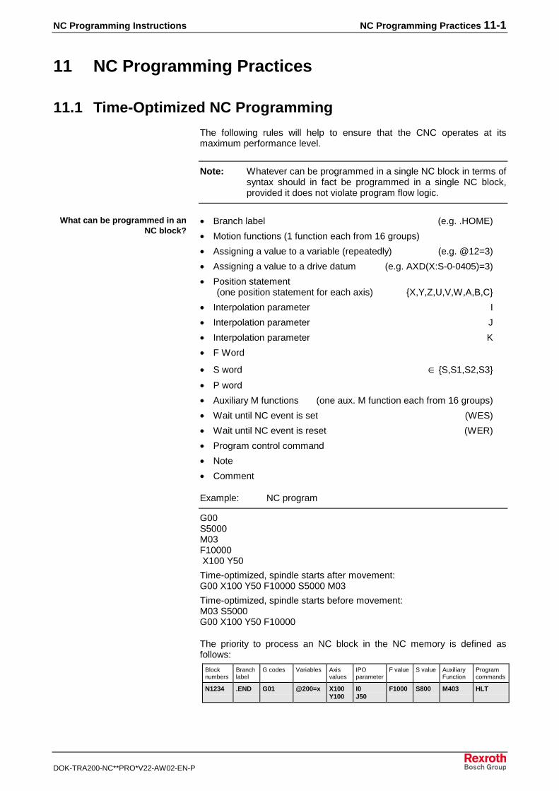
NC Programming Instructions NC Programming Practices 11-1
DOK-TRA200-NC**PRO*V22-AW02-EN-P
11 NC Programming Practices
11.1 Time-Optimized NC Programming
The following rules will help to ensure that the CNC operates at itsmaximum performance level.
Note: Whatever can be programmed in a single NC block in terms ofsyntax should in fact be programmed in a single NC block,provided it does not violate program flow logic.
• Branch label (e.g. .HOME)
• Motion functions (1 function each from 16 groups)
• Assigning a value to a variable (repeatedly) (e.g. @12=3)
• Assigning a value to a drive datum (e.g. AXD(X:S-0-0405)=3)
• Position statement (one position statement for each axis) {X,Y,Z,U,V,W,A,B,C}
• Interpolation parameter I
• Interpolation parameter J
• Interpolation parameter K
• F Word
• S word ∈ {S,S1,S2,S3}
• P word
• Auxiliary M functions (one aux. M function each from 16 groups)
• Wait until NC event is set (WES)
• Wait until NC event is reset (WER)
• Program control command
• Note
• Comment
Example: NC program
G00S5000M03F10000 X100 Y50
Time-optimized, spindle starts after movement:G00 X100 Y50 F10000 S5000 M03
Time-optimized, spindle starts before movement:M03 S5000G00 X100 Y50 F10000
The priority to process an NC block in the NC memory is defined asfollows:
Blocknumbers
Branchlabel
G codes Variables Axisvalues
IPOparameter
F value S value AuxiliaryFunction
Programcommands
N1234 .END G01 @200=x X100Y100
I0J50
F1000 S800 M403 HLT
What can be programmed in anNC block?
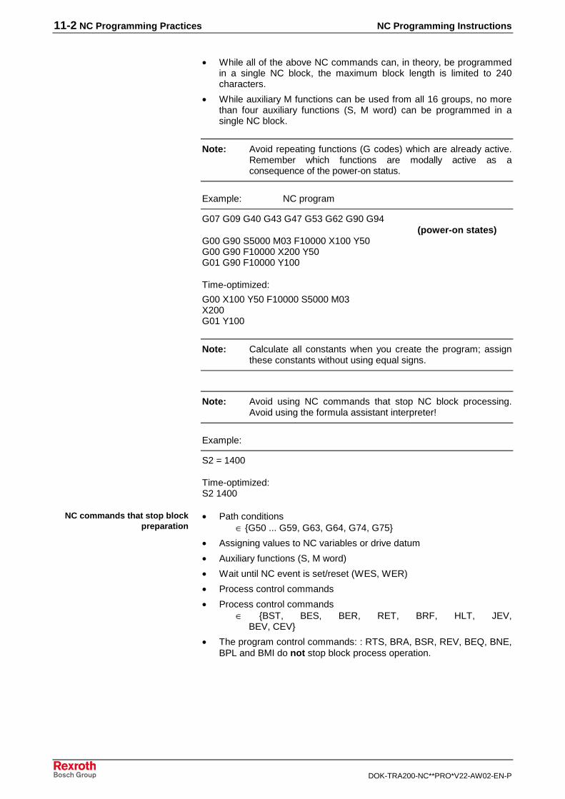
11-2 NC Programming Practices NC Programming Instructions
DOK-TRA200-NC**PRO*V22-AW02-EN-P
• While all of the above NC commands can, in theory, be programmedin a single NC block, the maximum block length is limited to 240characters.
• While auxiliary M functions can be used from all 16 groups, no morethan four auxiliary functions (S, M word) can be programmed in asingle NC block.
Note: Avoid repeating functions (G codes) which are already active.Remember which functions are modally active as aconsequence of the power-on status.
Example: NC program
G07 G09 G40 G43 G47 G53 G62 G90 G94(power-on states)
G00 G90 S5000 M03 F10000 X100 Y50G00 G90 F10000 X200 Y50G01 G90 F10000 Y100
Time-optimized:
G00 X100 Y50 F10000 S5000 M03X200G01 Y100
Note: Calculate all constants when you create the program; assignthese constants without using equal signs.
Note: Avoid using NC commands that stop NC block processing.Avoid using the formula assistant interpreter!
Example:
S2 = 1400
Time-optimized:S2 1400
• Path conditions∈ {G50 ... G59, G63, G64, G74, G75}
• Assigning values to NC variables or drive datum
• Auxiliary functions (S, M word)
• Wait until NC event is set/reset (WES, WER)
• Process control commands
• Process control commands ∈ {BST, BES, BER, RET, BRF, HLT, JEV, BEV, CEV}
• The program control commands: : RTS, BRA, BSR, REV, BEQ, BNE,BPL and BMI do not stop block process operation.
NC commands that stop blockpreparation
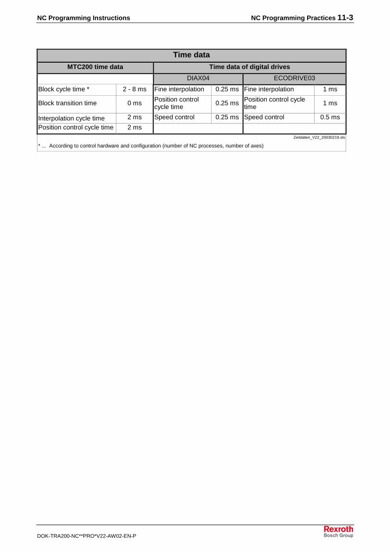
NC Programming Instructions NC Programming Practices 11-3
DOK-TRA200-NC**PRO*V22-AW02-EN-P
Time dataMTC200 time data Time data of digital drives
DIAX04 ECODRIVE03
Block cycle time * 2 - 8 ms Fine interpolation 0.25 ms Fine interpolation 1 ms
Block transition time 0 ms Position controlcycle time
0.25 ms Position control cycletime
1 ms
Interpolation cycle time 2 ms Speed control 0.25 ms Speed control 0.5 ms
Position control cycle time 2 msZeitdaten_V22_20030219.xls
* ... According to control hardware and configuration (number of NC processes, number of axes)
11-4 NC Programming Practices NC Programming Instructions
DOK-TRA200-NC**PRO*V22-AW02-EN-P
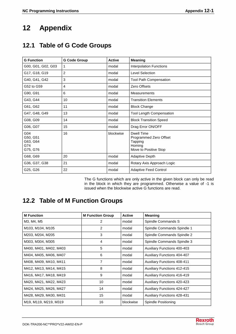
NC Programming Instructions Appendix 12-1
DOK-TRA200-NC**PRO*V22-AW02-EN-P
12 Appendix
12.1 Table of G Code Groups
G Function G Code Group Active Meaning
G00, G01, G02, G03 1 modal Interpolation Functions
G17, G18, G19 2 modal Level Selection
G40, G41, G42 3 modal Tool Path Compensation
G52 to G59 4 modal Zero Offsets
G90, G91 6 modal Measurements
G43, G44 10 modal Transition Elements
G61, G62 11 modal Block Change
G47, G48, G49 13 modal Tool Length Compensation
G08, G09 14 modal Block Transition Speed
G06, G07 15 modal Drag Error ON/OFF
G04G50, G51G63, G64G74G75, G76
16 blockwise Dwell TimeProgrammed Zero OffsetTappingHomingMove to Positive Stop
G68, G69 20 modal Adaptive Depth
G36, G37, G38 21 modal Rotary Axis Approach Logic
G25, G26 22 modal Adaptive Feed Control
The G functions which are only active in the given block can only be readin the block in which they are programmed. Otherwise a value of -1 isissued when the blockwise active G functions are read.
12.2 Table of M Function Groups
M Function M Function Group Active Meaning
M3, M4, M5 2 modal Spindle Commands S
M103, M104, M105 2 modal Spindle Commands Spindle 1
M203, M204, M205 3 modal Spindle Commands Spindle 2
M303, M304, M305 4 modal Spindle Commands Spindle 3
M400, M401, M402, M403 5 modal Auxiliary Functions 400-403
M404, M405, M406, M407 6 modal Auxiliary Functions 404-407
M408, M409, M410, M411 7 modal Auxiliary Functions 408-411
M412, M413, M414, M415 8 modal Auxiliary Functions 412-415
M416, M417, M418, M419 9 modal Auxiliary Functions 416-419
M420, M421, M422, M423 10 modal Auxiliary Functions 420-423
M424, M425, M426, M427 14 modal Auxiliary Functions 424-427
M428, M429, M430, M431 15 modal Auxiliary Functions 428-431
M19, M119, M219, M319 16 blockwise Spindle Positioning
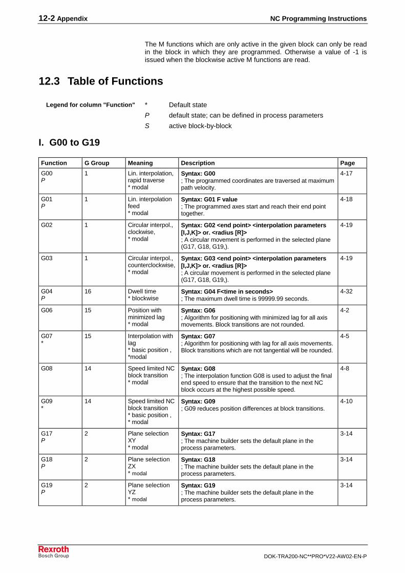
12-2 Appendix NC Programming Instructions
DOK-TRA200-NC**PRO*V22-AW02-EN-P
The M functions which are only active in the given block can only be readin the block in which they are programmed. Otherwise a value of -1 isissued when the blockwise active M functions are read.
12.3 Table of Functions
* Default state
P default state; can be defined in process parameters
S active block-by-block
I. G00 to G19
Function G Group Meaning Description Page
G00P
1 Lin. interpolation,rapid traverse* modal
Syntax: G00; The programmed coordinates are traversed at maximumpath velocity.
4-17
G01P
1 Lin. interpolationfeed* modal
Syntax: G01 F value; The programmed axes start and reach their end pointtogether.
4-18
G02 1 Circular interpol.,clockwise,* modal
Syntax: G02 <end point> <interpolation parameters[I,J,K]> or. <radius [R]>; A circular movement is performed in the selected plane(G17, G18, G19,).
4-19
G03 1 Circular interpol.,counterclockwise,* modal
Syntax: G03 <end point> <interpolation parameters[I,J,K]> or. <radius [R]>; A circular movement is performed in the selected plane(G17, G18, G19,).
4-19
G04P
16 Dwell time* blockwise
Syntax: G04 F<time in seconds>; The maximum dwell time is 99999.99 seconds.
4-32
G06 15 Position withminimized lag* modal
Syntax: G06; Algorithm for positioning with minimized lag for all axismovements. Block transitions are not rounded.
4-2
G07*
15 Interpolation withlag* basic position ,*modal
Syntax: G07; Algorithm for positioning with lag for all axis movements.Block transitions which are not tangential will be rounded.
4-5
G08 14 Speed limited NCblock transition* modal
Syntax: G08; The interpolation function G08 is used to adjust the finalend speed to ensure that the transition to the next NCblock occurs at the highest possible speed.
4-8
G09*
14 Speed limited NCblock transition* basic position ,* modal
Syntax: G09; G09 reduces position differences at block transitions.
4-10
G17P
2 Plane selectionXY* modal
Syntax: G17; The machine builder sets the default plane in theprocess parameters.
3-14
G18P
2 Plane selectionZX* modal
Syntax: G18; The machine builder sets the default plane in theprocess parameters.
3-14
G19P
2 Plane selectionYZ* modal
Syntax: G19; The machine builder sets the default plane in theprocess parameters.
3-14
Legend for column "Function"
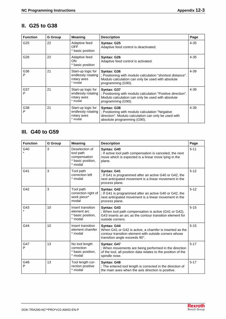
NC Programming Instructions Appendix 12-3
DOK-TRA200-NC**PRO*V22-AW02-EN-P
II. G25 to G38
Function G Group Meaning Description Page
G25 22 Adaptive feedOFF* basic position
Syntax: G25Adaptive feed control is deactivated.
4-35
G26 22 Adaptive feedON* basic position
Syntax: G26Adaptive feed control is activated.
4-35
G36P
21 Start-up logic forendlessly rotatingrotary axes* modal
Syntax: G36; Positioning with modulo calculation "shortest distance".Modulo calculation can only be used with absoluteprogramming (G90).
4-39
G37P
21 Start-up logic forendlessly rotatingrotary axes* modal
Syntax: G37; Positioning with modulo calculation "Positive direction".Modulo calculation can only be used with absoluteprogramming (G90).
4-39
G38P
21 Start-up logic forendlessly rotatingrotary axes* modal
Syntax: G38; Positioning with modulo calculation "Negativedirection". Modulo calculation can only be used withabsolute programming (G90).
4-39
III. G40 to G59
Function G Group Meaning Description Page
G40*
3 Deselection oftool pathcompensation* basic position,* modal
Syntax: G40; If active tool path compensation is canceled, the nextmove which is expected is a linear move lying in theplane.
5-11
G41 3 Tool pathcorrection left* modal
Syntax: G41; If G41 is programmed after an active G40 or G42, thenext anticipated movement is a linear movement in theprocess plane.
5-12
G42 3 Tool pathcorrection right ofwork piece*modal
Syntax: G42; If G41 is programmed after an active G40 or G42, thenext anticipated movement is a linear movement in theprocess plane.
5-12
G43*
10 Insert transitionelement arc* basic position,* modal
Syntax: G43; When tool path compensation is active (G41 or G42),G43 inserts an arc as the contour transition element foroutside corners.
5-15
G44 10 Insert transitionelement chamfer* modal
Syntax: G44When G41 or G42 is active, a chamfer is inserted as thecontour transition element with outside corners whosetransition angle exceeds 90°.
5-15
G47P
13 No tool lengthcorrection* basic position,* modal
Syntax: G47; When movements are being performed in the directionof the tool, all position data relates to the position of thespindle nose.
5-17
G48P
13 Tool length cor-rection positive* modal
Syntax: G48; The entered tool length is corrected in the direction ofthe main axes when the axis direction is positive.
5-17
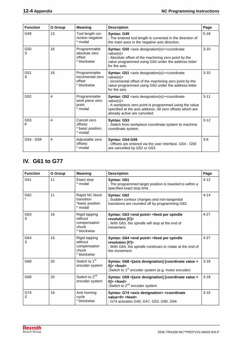
12-4 Appendix NC Programming Instructions
DOK-TRA200-NC**PRO*V22-AW02-EN-P
Function G Group Meaning Description Page
G49 13 Tool length cor-rection negative* modal
Syntax: G49; The entered tool length is corrected in the direction ofthe main axes in the negative axis direction.
5-18
G50S
16 Programmableabsolute zerooffset* blockwise
Syntax: G50 <axis designation(s)><coordinatevalue(s)>; Absolute offset of the machining zero point by thevalue programmed using G50 under the address letterfor the axis.
3-10
G51S
16 Programmableincremental zerooffset* blockwise
Syntax: G51 <axis designation(s)><coordinatevalue(s)>; incremental offset of the machining zero point by thevalue programmed using G50 under the address letterfor the axis.
3-10
G52 4 Programmablework piece zeropoint* modal
Syntax: G52 <axis designation(s)><coordinatevalue(s)>; A workpiece zero point is programmed using the valuespecified at the axis address. All zero offsets which arealready active are canceled.
3-11
G53P
4 Cancel zerooffsets* basic position,* modal
Syntax: G53; Switch from workpiece coordinate system to machinecoordinate system.
3-12
G54 - G59 4 Adjustable zerooffsets* modal
Syntax: G54-G59; Offsets are entered via the user interface. G54 - G59are cancelled by G52 or G53.
3-8
IV. G61 to G77
Function G Group Meaning Description Page
G61 11 Exact stop* modal
Syntax: G61; The programmed target position is traveled to within aspecified exact stop limit.
4-12
G62*
11 Rapid NC blocktransition*basic position* modal
Syntax: G62; Sudden contour changes and non-tangentialtransitions are rounded off by programming G62.
4-14
G63S
16 Rigid tappingwithoutcompensationchuck* blockwise
Syntax: G63 <end point> <feed per spindlerevolution [F]>; With G63, the spindle will stop at the end ofmovement.
4-27
G64S
16 Rigid tappingwithoutcompensationchuck* blockwise
Syntax: G64 <end point> <feed per spindlerevolution [F]>; With G64, the spindle continues to rotate at the end ofthe movement.
4-27
G68 20 Switch to 1st
encoder systemSyntax: G68 <[axis designation] [coordinate value =0]> <feed>;Switch to 1st
encoder system (e.g. motor encoder)
3-18
G69 20 Switch to 2nd
encoder systemSyntax: G69 <[axis designation] [coordinate value =0]> <feed>;Switch to 2nd
encoder system
3-18
G74S
16 Axis homingcycle* blockwise
Syntax: G74 <axis designation> <coordinatevalue=0> <feed>; G74 activates G40, G47, G53, G90, G94
3-15
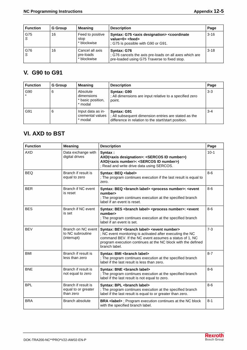
NC Programming Instructions Appendix 12-5
DOK-TRA200-NC**PRO*V22-AW02-EN-P
Function G Group Meaning Description Page
G75S
16 Feed to positivestop* blockwise
Syntax: G75 <axis designation> <coordinatevalue=0> <feed>; G75 is possible with G90 or G91.
3-16
G76S
16 Cancel all axispre-loads* blockwise
Syntax: G76; G76 cancels the axis pre-loads on all axes which arepre-loaded using G75 Traverse to fixed stop.
3-18
V. G90 to G91
Function G Group Meaning Description Page
G90*
6 Absolutedimensions* basic position,* modal
Syntax: G90; All dimensions are input relative to a specified zeropoint.
3-3
G91 6 Input data as in-cremental values* modal
Syntax: G91; All subsequent dimension entries are stated as thedifference in relation to the start/start position.
3-4
VI. AXD to BST
Function Meaning Description Page
AXD Data exchange withdigital drives
Syntax :AXD(<axis designation>: <SERCOS ID number>)AXD(<axis number>: <SERCOS ID number>); Read and write drive data using SERCOS.
10-1
BEQ Branch if result isequal to zero
Syntax: BEQ <label>; The program continues execution if the last result is equal tozero.
8-6
BER Branch if NC eventis reset
Syntax: BEQ <branch label> <process number>: <eventnumber>; The program continues execution at the specified branchlabel if an event is reset.
8-6
BES Branch if NC eventis set
Syntax: BES <branch label> <process number>: <eventnumber>; The program continues execution at the specified branchlabel if an event is set.
8-6
BEV Branch on NC eventto NC subroutine(interrupt)
Syntax: BEV <branch label> <event number>; NC event monitoring is activated after executing the NCcommand BEV. If the NC event assumes a status of 1, NCprogram execution continues at the NC block with the definedbranch label.
7-3
BMI Branch if result isless than zero
Syntax: BMI <branch label>; The program continues execution at the specified branchlabel if the last result is less than zero.
8-7
BNE Branch if result isnot equal to zero
Syntax: BNE <branch label>; The program continues execution at the specified branchlabel if the last result is not equal to zero.
8-6
BPL Branch if result isequal to or greaterthan zero
Syntax: BPL <branch label>; The program continues execution at the specified branchlabel if the last result is equal to or greater than zero.
8-6
BRA Branch absolute BRA <label> ; Program execution continues at the NC blockwith the specified branch label.
8-1
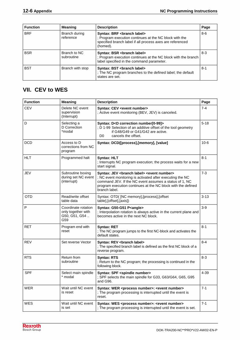
12-6 Appendix NC Programming Instructions
DOK-TRA200-NC**PRO*V22-AW02-EN-P
Function Meaning Description Page
BRF Branch duringreference
Syntax: BRF <branch label>; Program execution continues at the NC block with thespecified branch label if all process axes are referenced(homed).
8-6
BSR Branch to NCsubroutine
Syntax: BSR <branch label>; Program execution continues at the NC block with the branchlabel specified in the command parameter.
8-3
BST Branch with stop Syntax: BST <branch label>; The NC program branches to the defined label; the defaultstates are set.
8-1
VII. CEV to WES
Function Meaning Description Page
CEV Delete NC eventsupervision(Interrupt)
Syntax: CEV <event number>; Active event monitoring (BEV, JEV) is canceled.
7-4
D Selecting aD Correction*modal
Syntax: D<D correction number[0-99]>; D 1-99 Selection of an additive offset of the tool geometry if G48/G49 or G41/G42 are active. D0 cancels the offset.
5-18
DCD Access to Dcorrections from NCprogram
Syntax: DCD([process],[memory], [value] 10-6
HLT Programmed halt Syntax: HLT; Interrupts NC program execution; the process waits for a newstart signal.
8-1
JEV Subroutine boxingduring set NC event(interrupt)
Syntax: JEV <branch label> <event number>; NC event monitoring is activated after executing the NCcommand JEV. If the NC event assumes a status of 1, NCprogram execution continues at the NC block with the definedbranch label.
7-3
OTD Read/write offsettable data
Syntax: OTD( [NC memory],[process],[offsettable],[offset],[axis])
3-13
P Coordinate rotationonly together withG50, G51, G54 ..G59
Syntax: G50-G51 P<angle>; Interpolation rotation is always active in the current plane andbecomes active in the next NC block.
3-9
RET Program end withreset
Syntax: RET; The NC program jumps to the first NC-block and activates thedefault states.
8-1
REV Set reverse Vector Syntax: REV <branch label>; The specified branch label is defined as the first NC block of areverse program.
8-4
RTS Return fromsubroutine
Syntax: RTS; Return to the NC program; the processing is continued in thefollowing block.
8-3
SPF Select main spindle* modal
Syntax: SPF <spindle number>; SPF selects the main spindle for G33, G63/G64, G65, G95and G96.
4-39
WER Wait until NC eventis reset
Syntax: WER <process number>: <event number>; The program processing is interrupted until the event isreset.
7-1
WES Wait until NC eventis set
Syntax: WES <process number>: <event number>; The program processing is interrupted until the event is set.
7-1
NC Programming Instructions Index 13-1
DOK-TRA200-NC**PRO*V22-AW02-EN-P
13 Index
665017 3-17, 3-1865018 3-17, 3-1865091 4-3765092 4-37
AAbsolute measuring units - G90 2-1, 2-4, 2-5, 3-3, 3-4, 3-8, 3-10, 3-11, 3-12, 3-15, 3-17, 4-1, 4-3, 4-6, 4-9, 4-11, 4-13, 4-15, 4-17, 4-18, 4-19, 4-20, 4-21, 4-22,4-24, 4-26, 4-28, 4-29, 4-30, 4-33, 4-39, 8-4, 9-3, 9-8, 10-2, 11-2, 12-1, 12-3, 12-4, 12-5Access to tool data from NC program - TLD 10-8Active plane rotation together with G50, G51, G54 .. G59 - P 3-9, 3-10, 3-11, 9-2, 12-6Adaptive depth - Cxx.087 3-18, 3-19Adaptive depth, switch to 1st
encoder system - G68 3-18, 3-19, 9-3, 12-1, 12-4Adaptive depth, switch to 2st
encoder system - G69 3-18, 3-19, 9-3, 12-1, 12-4Adaptive feed control - Bxx.062 4-35Adaptive feed control, reference axis for - Bxx.063 4-35Adjustable zero offset - G54 2-1, 2-2, 2-4, 2-5, 3-3, 3-4, 3-7, 3-8, 3-9, 3-10, 3-11,4-3, 4-6, 4-9, 4-11, 4-13, 4-15, 4-17, 4-18, 4-19, 4-21, 4-22, 4-24, 4-26, 4-28, 4-29, 4-30, 4-33, 5-14, 9-8, 10-2, 10-5, 10-6, 12-4, 12-6Adjustable zero offset - G55 10-5Adjustable zero offset - G56 10-5Adjustable zero offset - G57 10-5Adjustable zero offset - G58 10-5Adjustable zero offset - G59 3-7, 3-8, 3-9, 9-3, 10-5, 11-2, 12-1, 12-3, 12-4, 12-6Amplification - Bxx.068 4-35Arc, inserting transition element - G43 5-3, 5-4, 5-15, 9-3, 11-2, 12-1, 12-3AXD 3-17, 3-18, 4-37, 10-1, 10-2, 10-4, 10-8, 11-1, 12-5Axis designation - Cxx.001 3-1Axis functions, reduced motor torque on positive stop - 65018 3-17, 3-18Axis functions, reduced motor torque upon driving against positive stop - 650173-17, 3-18Axis functions, reduced motor torque upon driving against positive stop - P-7-3577 3-17, 3-18Axis-preload, cancel all - G76 3-17, 3-18, 9-3, 12-1, 12-5
BBEQ 8-6, 8-7, 11-2, 12-5BER 8-6, 11-2, 12-5BES 7-2, 8-6, 11-2, 12-5Block transition, velocity-limited - G09 3-19, 4-8, 4-10, 4-11, 4-12, 4-17, 9-3, 11-2, 12-1, 12-2Block transition, velocity-optimal - G08 3-19, 4-3, 4-6, 4-8, 4-9, 4-10, 4-12, 4-13,4-14, 4-15, 4-17, 4-24, 4-27, 4-28, 4-29, 4-30, 4-33, 5-14, 6-1, 9-3, 9-4, 9-8, 10-1,10-2, 12-1, 12-2BMI 8-7, 11-2, 12-5BNE 8-6, 8-7, 11-2, 12-5BPL 8-6, 8-7, 11-2, 12-5BRA 8-1, 8-7, 11-2, 12-5Branch command absolute branch - BRA 8-1, 8-7, 11-2, 12-5Branch command if NC event is reset - BER 8-6, 11-2, 12-5Branch command if NC event is set - BES 7-2, 8-6, 11-2, 12-5Branch command if NC event is set - JEV 7-3, 7-4, 11-2, 12-6Branch command if reference - BRF 8-6, 11-2, 12-6Branch command if result is equal to zero - BEQ 8-6, 8-7, 11-2, 12-5Branch command if result is greater than or equal to zero - BPL 8-6, 8-7, 11-2,12-5Branch command if result is smaller than zero - BMI 8-7, 11-2, 12-5Branch command if result is unequal to zero - BNE 8-6, 8-7, 11-2, 12-5Branch command if T0 was set - BTE 8-1
13-2 Index NC Programming Instructions
DOK-TRA200-NC**PRO*V22-AW02-EN-P
Branch command, with stop - BST 3-18, 4-2, 4-5, 4-8, 4-10, 4-12, 4-14, 4-32, 4-38, 4-39, 4-40, 5-11, 5-12, 5-15, 5-17, 5-18, 5-20, 8-1, 8-4, 11-2, 12-5, 12-6BRF 8-6, 11-2, 12-6BSR 2-4, 3-3, 3-4, 3-8, 3-10, 3-11, 3-12, 4-28, 4-29, 4-30, 4-31, 8-3, 9-8, 11-2,12-6BST 3-18, 4-2, 4-5, 4-8, 4-10, 4-12, 4-14, 4-32, 4-38, 4-39, 4-40, 5-11, 5-12, 5-15, 5-17, 5-18, 5-20, 8-1, 8-4, 11-2, 12-5, 12-6BTE 8-1Bxx.002 2-4Bxx.005 4-32Bxx.007 4-17Bxx.032 2-2Bxx.062 4-35Bxx.063 4-35Bxx.064 4-35Bxx.065 4-35, 4-36Bxx.066 4-35Bxx.067 4-35, 4-36Bxx.068 4-35Bxx.069 4-35
CCall subroutine if NC event is set (interrupt) - BEV 7-3, 7-4, 11-2, 12-5, 12-6Cancel all axis-preload - G76 3-17, 3-18, 9-3, 12-1, 12-5CEV 7-3, 7-4, 11-2, 12-6Chamfer, Inserting transition element - G44 5-3, 5-15, 9-3, 12-1, 12-3Clockwise circular interpolation - G02 4-3, 4-6, 4-13, 4-15, 4-17, 4-18, 4-19, 4-20, 4-21, 4-22, 4-23, 4-24, 4-26, 5-14, 9-3, 10-2, 12-1, 12-2Clockwise, circular interpolation - G02 4-3, 4-6, 4-13, 4-15, 4-17, 4-18, 4-19, 4-20, 4-21, 4-22, 4-23, 4-24, 4-26, 5-14, 9-3, 10-2, 12-1, 12-2Constant cutting speed- G96 12-6Counterclockwise circular interpolation - G03 4-3, 4-6, 4-13, 4-15, 4-17, 4-18, 4-19, 4-20, 4-22, 4-23, 5-14, 9-3, 9-8, 10-2, 12-1, 12-2Counterclockwise, circular interpolation - G03 4-3, 4-6, 4-13, 4-15, 4-17, 4-18, 4-19, 4-20, 4-22, 4-23, 5-14, 9-3, 9-8, 10-2, 12-1, 12-2Cutting speed, constant - G96 12-6Cxx.001 3-1Cxx.013 3-15Cxx.016 4-32Cxx.019 3-15Cxx.023 4-12Cxx.044 3-16, 3-17Cxx.045 3-17Cxx.049 4-37Cxx.087 3-18, 3-19Cxx.088 3-18, 3-19Cxx.089 3-18, 3-19Cxx.090 3-18, 3-19Cxx.091 3-18, 3-19
DD correction, access to 8-7, 10-6, 10-7, 10-8, 12-6D correction, deselection of - D0 2-1, 5-18, 5-20, 8-4, 12-6D0 2-1, 5-18, 5-20, 8-4, 12-6Data exchange with drives - AXD 3-17, 3-18, 4-37, 10-1, 10-2, 10-4, 10-8, 11-1,12-5DCD 8-7, 10-6, 10-7, 10-8, 12-6Decimal places, programmable 2-4Depth, adaptive - Cxx.087 3-18, 3-19Depth, adaptive, negative travel range limit of 2. encoder - Cxx.090 3-18, 3-19Depth, adaptive, permissible sensor deflection Cxx.091 3-18, 3-19Depth, adaptive, positive travel range limit of 2. encoder - Cxx.089 3-18, 3-19Depth, adaptive, reference position of 2. encoder - Cxx.088 3-18, 3-19Deselection of all offset - G53 3-8, 3-11, 3-12, 3-13, 3-15, 8-4, 11-2, 12-4Deselection of tool path correction - G40 3-12, 3-15, 5-11, 5-12, 5-14, 5-15, 8-4,9-3, 9-8, 11-2, 12-1, 12-3, 12-4Dwell time – G04 2-4, 3-3, 3-4, 3-8, 3-10, 4-28, 4-31, 4-32, 4-33, 9-2, 9-3, 12-1,12-2
NC Programming Instructions Index 13-3
DOK-TRA200-NC**PRO*V22-AW02-EN-P
EError clearing - PxxC.CLEAR 4-32, 5-20Event monitoring, deleting the - CEV 7-3, 7-4, 11-2, 12-6Event, subroutine call during set - BEV 7-3, 7-4, 11-2, 12-5, 12-6Event, wait until NC event is reset - WER 7-1, 11-1, 11-2, 12-6Event, wait until NC event is set - WES 2-2, 7-1, 11-1, 11-2, 12-6
FFeed control, adaptive 4-35Feed control, adaptive - Bxx.062 4-35Feed per rotation - G95 12-6Feed reduction, maximum - Bxx.067 4-35, 4-36Feed to positive stop – G75 3-16, 3-17, 3-18, 4-35, 9-3, 11-2, 12-1, 12-5Feed, linear interpolation - G01 2-1, 2-2, 2-3, 2-5, 3-3, 3-4, 3-8, 3-10, 3-11, 3-12,3-17, 4-3, 4-6, 4-9, 4-11, 4-13, 4-15, 4-17, 4-18, 4-19, 4-21, 4-22, 4-23, 4-24, 4-26, 4-28, 4-29, 4-30, 4-33, 4-34, 5-14, 9-3, 9-8, 10-2, 11-1, 11-2, 12-1, 12-2
GG00 2-1, 2-4, 2-5, 3-3, 3-4, 3-8, 3-10, 3-11, 3-12, 3-17, 4-3, 4-6, 4-9, 4-11, 4-12,4-13, 4-14, 4-15, 4-17, 4-18, 4-19, 4-21, 4-22, 4-24, 4-26, 4-28, 4-29, 4-30, 4-31,4-33, 5-14, 5-18, 9-3, 9-8, 10-2, 11-1, 11-2, 12-1, 12-2G01 2-1, 2-2, 2-3, 2-5, 3-3, 3-4, 3-8, 3-10, 3-11, 3-12, 3-17, 4-3, 4-6, 4-9, 4-11,4-13, 4-15, 4-17, 4-18, 4-19, 4-21, 4-22, 4-23, 4-24, 4-26, 4-28, 4-29, 4-30, 4-33,4-34, 5-14, 9-3, 9-8, 10-2, 11-1, 11-2, 12-1, 12-2G02 4-3, 4-6, 4-13, 4-15, 4-17, 4-18, 4-19, 4-20, 4-21, 4-22, 4-23, 4-24, 4-26, 5-14, 9-3, 10-2, 12-1, 12-2G03 4-3, 4-6, 4-13, 4-15, 4-17, 4-18, 4-19, 4-20, 4-22, 4-23, 5-14, 9-3, 9-8, 10-2,12-1, 12-2G04 2-4, 3-3, 3-4, 3-8, 3-10, 4-28, 4-31, 4-32, 4-33, 9-2, 9-3, 12-1, 12-2G06 4-2, 4-3, 4-5, 4-6, 4-8, 4-9, 4-11, 4-13, 4-15, 4-18, 4-19, 4-21, 4-22, 4-24, 4-26, 4-27, 4-28, 4-29, 4-30, 4-33, 5-14, 9-3, 9-4, 9-8, 10-2, 12-1, 12-2G07 4-2, 4-5, 4-6, 4-7, 4-8, 9-3, 11-2, 12-1, 12-2G08 3-19, 4-3, 4-6, 4-8, 4-9, 4-10, 4-12, 4-13, 4-14, 4-15, 4-17, 4-24, 4-27, 4-28,4-29, 4-30, 4-33, 5-14, 6-1, 9-3, 9-4, 9-8, 10-1, 10-2, 12-1, 12-2G09 3-19, 4-8, 4-10, 4-11, 4-12, 4-17, 9-3, 11-2, 12-1, 12-2G17 3-9, 3-13, 3-14, 4-1, 4-19, 4-22, 4-23, 4-25, 5-17, 9-3, 12-1, 12-2G18 3-13, 3-14, 4-1, 4-19, 4-23, 4-25, 5-17, 9-3, 12-1, 12-2G19 3-14, 4-8, 4-12, 4-13, 4-14, 4-15, 4-27, 9-3, 12-1, 12-2, 12-4G20 3-13G21 3-13G22 3-13G25 4-35, 4-36, 9-3, 12-1, 12-3G26 4-35, 4-36, 9-3, 12-1, 12-3G33 12-6G36 4-39, 4-40, 9-3, 12-1, 12-3G37 4-39, 4-40, 9-3, 12-1, 12-3G38 4-39, 4-40, 9-3, 12-1, 12-3G40 3-12, 3-15, 5-11, 5-12, 5-14, 5-15, 8-4, 9-3, 9-8, 11-2, 12-1, 12-3, 12-4G41 3-12, 4-3, 4-6, 5-2, 5-7, 5-11, 5-12, 5-13, 5-15, 5-19, 5-20, 9-3, 10-1, 10-2,12-1, 12-3, 12-6G42 3-12, 5-2, 5-7, 5-11, 5-12, 5-13, 5-14, 5-15, 5-19, 5-20, 9-3, 9-8, 10-1, 12-1,12-3, 12-6G43 5-4, 5-15G44 5-3, 5-15, 9-3, 12-1, 12-3G47 5-17, 5-18, 8-4, 9-3, 11-2, 12-1, 12-3, 12-4G48 5-17, 5-18, 5-19, 5-20, 9-3, 12-1, 12-3, 12-6G49 5-17, 5-18, 5-19, 5-20, 9-3, 12-1, 12-4, 12-6G50 3-7, 3-8, 3-9, 3-10, 3-11, 9-2, 9-3, 10-5, 11-2, 12-1, 12-4, 12-6G51 2-5, 3-7, 3-8, 3-9, 3-10, 9-3, 10-5, 12-1, 12-4, 12-6G52 3-7, 3-8, 3-9, 3-11, 3-12, 9-3, 10-5, 12-1, 12-4G53 3-8, 3-11, 3-12, 3-13, 3-15, 8-4, 11-2, 12-4G54 2-1, 2-2, 2-4, 2-5, 3-3, 3-4, 3-7, 3-8, 3-9, 3-10, 3-11, 4-3, 4-6, 4-9, 4-11, 4-13, 4-15, 4-17, 4-18, 4-19, 4-21, 4-22, 4-24, 4-26, 4-28, 4-29, 4-30, 4-33, 5-14, 9-8, 10-2, 10-5, 10-6, 12-4, 12-6G55 10-5G56 10-5G57 10-5
13-4 Index NC Programming Instructions
DOK-TRA200-NC**PRO*V22-AW02-EN-P
G58 10-5G59 3-7, 3-8, 3-9, 9-3, 10-5, 11-2, 12-1, 12-3, 12-4, 12-6G61 4-8, 4-12, 4-13, 4-14, 4-15, 4-27, 9-3, 12-1, 12-4G62 4-12, 4-14, 4-15, 4-16, 4-17, 9-3, 11-2, 12-1, 12-4G63 4-27, 4-28, 4-29, 4-30, 4-31, 4-32, 4-39, 9-3, 11-2, 12-1, 12-4, 12-6G64 4-27, 4-28, 4-30, 4-31, 4-32, 4-39, 9-3, 11-2, 12-1, 12-4, 12-6G65 12-6G68 3-18, 3-19, 9-3, 12-1, 12-4G69 3-18, 3-19, 9-3, 12-1, 12-4G74 2-1, 3-15, 3-17, 4-35, 8-4, 9-3, 11-2, 12-1, 12-4G75 3-16, 3-17, 3-18, 4-35, 9-3, 11-2, 12-1, 12-5G76 3-17, 3-18, 9-3, 12-1, 12-5G77 12-4G90 2-1, 2-4, 2-5, 3-3, 3-4, 3-8, 3-10, 3-11, 3-12, 3-15, 3-17, 4-1, 4-3, 4-6, 4-9,4-11, 4-13, 4-15, 4-17, 4-18, 4-19, 4-20, 4-21, 4-22, 4-24, 4-26, 4-28, 4-29, 4-30,4-33, 4-39, 8-4, 9-3, 9-8, 10-2, 11-2, 12-1, 12-3, 12-4, 12-5G91 3-3, 3-4, 3-12, 3-17, 4-1, 4-20, 4-22, 4-26, 4-39, 9-3, 9-8, 12-1, 12-5G94 3-15, 4-32, 11-2, 12-4G95 12-6G96 12-6
HHLT 2-2, 8-1, 8-7, 8-8, 11-1, 11-2, 12-6Home position required - Bxx.032 2-2Homing speed for rotary axis mode - Cxx.019 3-15Homing, query magazine - MRF 2-1Homing, tool memory - MRF 2-1
IIdling torque measurement - ITM 4-37Idling torque, measurement of - ITM 4-37Incremental Dimensions - G91 3-3, 3-4, 3-12, 3-17, 4-1, 4-20, 4-22, 4-26, 4-39,9-3, 9-8, 12-1, 12-5Inserting a chamfer transition element - G44 5-3, 5-15, 9-3, 12-1, 12-3Inserting an arc transition element G43 5-3, 5-4, 5-15, 9-3, 11-2, 12-1, 12-3Interpolation with lag - G07 4-2, 4-5, 4-6, 4-7, 4-8, 9-3, 11-2, 12-1, 12-2Interpolation, minimized lag - G06 4-2, 4-3, 4-5, 4-6, 4-8, 4-9, 4-11, 4-13, 4-15,4-18, 4-19, 4-21, 4-22, 4-24, 4-26, 4-27, 4-28, 4-29, 4-30, 4-33, 5-14, 9-3, 9-4, 9-8, 10-2, 12-1, 12-2Interpolation, with lag - G07 4-2, 4-5, 4-6, 4-7, 4-8, 9-3, 11-2, 12-1, 12-2ITM 4-37
JJEV 7-3, 7-4, 11-2, 12-6
LLinear interpolation rapid traverse - G00 2-1, 2-4, 2-5, 3-3, 3-4, 3-8, 3-10, 3-11,3-12, 3-17, 4-3, 4-6, 4-9, 4-11, 4-12, 4-13, 4-14, 4-15, 4-17, 4-18, 4-19, 4-21, 4-22, 4-24, 4-26, 4-28, 4-29, 4-30, 4-31, 4-33, 5-14, 5-18, 9-3, 9-8, 10-2, 11-1, 11-2, 12-1, 12-2Linear interpolation, feed - G01 2-1, 2-2, 2-3, 2-5, 3-3, 3-4, 3-8, 3-10, 3-11, 3-12,3-17, 4-3, 4-6, 4-9, 4-11, 4-13, 4-15, 4-17, 4-18, 4-19, 4-21, 4-22, 4-23, 4-24, 4-26, 4-28, 4-29, 4-30, 4-33, 4-34, 5-14, 9-3, 9-8, 10-2, 11-1, 11-2, 12-1, 12-2
MMachine data elements, read and write - MTD 10-8Machining torque, limiting - Bxx.064 4-35Machining torque, maximum - Bxx.066 4-35Machining torque, minimum - Bxx.065 4-35, 4-36Measured functions, measuring period for standstill torque determination - P-7-3651 4-37Measuring duration - Bxx.069 4-35Measuring functions, measured standstill torque -65092 4-37
NC Programming Instructions Index 13-5
DOK-TRA200-NC**PRO*V22-AW02-EN-P
Measuring functions, measuring period for standstill torque determination -650914-37Measuring units, absolute - G90 2-1, 2-4, 2-5, 3-3, 3-4, 3-8, 3-10, 3-11, 3-12, 3-15, 3-17, 4-1, 4-3, 4-6, 4-9, 4-11, 4-13, 4-15, 4-17, 4-18, 4-19, 4-20, 4-21, 4-22,4-24, 4-26, 4-28, 4-29, 4-30, 4-33, 4-39, 8-4, 9-3, 9-8, 10-2, 11-2, 12-1, 12-3, 12-4, 12-5Measuring units, incremental - G91 3-3, 3-4, 3-12, 3-17, 4-1, 4-20, 4-22, 4-26,4-39, 9-3, 9-8, 12-1, 12-5Minimized lag interpolation - G06 4-2, 4-3, 4-5, 4-6, 4-8, 4-9, 4-11, 4-13, 4-15, 4-18, 4-19, 4-21, 4-22, 4-24, 4-26, 4-27, 4-28, 4-29, 4-30, 4-33, 5-14, 9-3, 9-4, 9-8,10-2, 12-1, 12-2MRF 2-1MTD 10-8Multifunction interpolator, table factor for interpolator 1 - P-7-3616 10-4, 10-8
NNC block transition, rapid - G62 4-12, 4-14, 4-15, 4-16, 4-17, 9-3, 11-2, 12-1, 12-4
OO 10-5Offset data, read and write - OTD 3-13, 10-4, 10-5, 10-6, 10-8, 12-6Offset database, selection of 10-5Offset, absolute 3-7, 3-8, 3-9, 3-10, 3-11, 9-2, 9-3, 10-5, 11-2, 12-1, 12-4, 12-6Offset, incremental 2-5, 3-7, 3-8, 3-9, 3-10, 9-3, 10-5, 12-1, 12-4, 12-6Offsets, deselection of all - G53 3-8, 3-11, 3-12, 3-13, 3-15, 8-4, 11-2, 12-4OTD 3-13, 10-4, 10-5, 10-6, 10-8, 12-6
PP 3-9, 3-10, 3-11, 9-2, 12-6P-7-3577 3-17, 3-18P-7-3578 3-17, 3-18P-7-3616 10-4, 10-8P-7-3651 4-37Path acceleration, maximum - Bxx.007 4-17Path velocity, maximum - Bxx.005 4-32Plane selection XY - G17 3-9, 3-13, 3-14, 4-1, 4-19, 4-22, 4-23, 4-25, 5-17, 9-3,12-1, 12-2Plane selection YZ - G19 3-13, 3-14, 4-1, 4-19, 4-23, 4-25, 5-17, 9-3, 12-1, 12-2Plane selection ZX - G18 3-13, 3-14, 4-1, 4-19, 4-23, 4-25, 5-17, 9-3, 12-1, 12-2Plane selection, free - G20 3-13Plane selection, free - G21 3-13Plane selection, free - G22 3-13Positioning window - Cxx.023 4-12Positive stop, feed to – G75 3-16, 3-17, 3-18, 4-35, 9-3, 11-2, 12-1, 12-5Positive stop, maximum speed during approaching - Cxx.045 3-17Positive stop, reduced torque at - Cxx.044 3-16, 3-17Program end with reset - RET 2-1, 2-4, 3-3, 3-4, 3-8, 3-10, 3-11, 3-12, 3-17, 3-18, 4-3, 4-5, 4-6, 4-9, 4-10, 4-11, 4-13, 4-14, 4-15, 4-18, 4-19, 4-21, 4-22, 4-24,4-26, 4-27, 4-28, 4-29, 4-30, 4-31, 4-32, 4-33, 4-38, 4-39, 4-40, 5-11, 5-12, 5-14,5-15, 5-17, 5-18, 5-20, 8-1, 8-4, 8-8, 9-8, 10-2, 11-2, 12-6Programmable absolute offset - G50 3-7, 3-8, 3-9, 3-10, 3-11, 9-2, 9-3, 10-5, 11-2, 12-1, 12-4, 12-6Programmable incremental zero offset - G51 2-5, 3-7, 3-8, 3-9, 3-10, 9-3, 10-5,12-1, 12-4, 12-6Programmed halt HLT 2-2, 8-1, 8-7, 8-8, 11-1, 11-2, 12-6Programmed workpiece zero point - G52 3-7, 3-8, 3-9, 3-11, 3-12, 9-3, 10-5, 12-1, 12-4PxxC.CLEAR 4-32, 5-20
RRapid NC block transition - G62 4-12, 4-14, 4-15, 4-16, 4-17, 9-3, 11-2, 12-1, 12-4Rapid traverse, linear interpolation - G00 2-1, 2-4, 2-5, 3-3, 3-4, 3-8, 3-10, 3-11,3-12, 3-17, 4-3, 4-6, 4-9, 4-11, 4-12, 4-13, 4-14, 4-15, 4-17, 4-18, 4-19, 4-21, 4-
13-6 Index NC Programming Instructions
DOK-TRA200-NC**PRO*V22-AW02-EN-P
22, 4-24, 4-26, 4-28, 4-29, 4-30, 4-31, 4-33, 5-14, 5-18, 9-3, 9-8, 10-2, 11-1, 11-2, 12-1, 12-2Read and write machine data elements - MTD 10-8Read and write offset data - OTD 3-13, 10-4, 10-5, 10-6, 10-8, 12-6Reduced motor torque on positive stop - P-7-3578 3-17, 3-18Reference position - Cxx.013 3-15Reference spindle, selection of - SPF 4-27, 4-39, 9-2, 12-6Referencing axles - G74 2-1, 3-15, 3-17, 4-35, 8-4, 9-3, 11-2, 12-1, 12-4Referencing, axles - G74 2-1, 3-15, 3-17, 4-35, 8-4, 9-3, 11-2, 12-1, 12-4Repositioning and restarting - G77 12-4Reset, program end - RET 2-1, 2-4, 3-3, 3-4, 3-8, 3-10, 3-11, 3-12, 3-17, 3-18,4-3, 4-5, 4-6, 4-9, 4-10, 4-11, 4-13, 4-14, 4-15, 4-18, 4-19, 4-21, 4-22, 4-24, 4-26,4-27, 4-28, 4-29, 4-30, 4-31, 4-32, 4-33, 4-38, 4-39, 4-40, 5-11, 5-12, 5-14, 5-15,5-17, 5-18, 5-20, 8-1, 8-4, 8-8, 9-8, 10-2, 11-2, 12-6Restarting, repositioning and - G77 12-4RET 2-1, 2-4, 3-3, 3-4, 3-8, 3-10, 3-11, 3-12, 3-17, 3-18, 4-3, 4-5, 4-6, 4-9, 4-10,4-11, 4-13, 4-14, 4-15, 4-18, 4-19, 4-21, 4-22, 4-24, 4-26, 4-27, 4-28, 4-29, 4-30,4-31, 4-32, 4-33, 4-38, 4-39, 4-40, 5-11, 5-12, 5-14, 5-15, 5-17, 5-18, 5-20, 8-1,8-4, 8-8, 9-8, 10-2, 11-2, 12-6Return to subroutine - RTS 2-4, 3-3, 3-4, 3-8, 3-10, 3-11, 3-12, 4-28, 4-29, 4-30,4-31, 7-3, 8-2, 8-3, 8-4, 9-8, 11-2, 12-6REV 8-4, 8-5, 11-2, 12-6Reverse vector, set - REV 8-4, 8-5, 11-2, 12-6Rigid tapping - G63 4-27, 4-28, 4-29, 4-30, 4-31, 4-32, 4-39, 9-3, 11-2, 12-1, 12-4, 12-6Rigid tapping - G64 4-27, 4-28, 4-30, 4-31, 4-32, 4-39, 9-3, 11-2, 12-1, 12-4, 12-6Rigid, tapping - G63 4-27, 4-28, 4-29, 4-30, 4-31, 4-32, 4-39, 9-3, 11-2, 12-1, 12-4, 12-6Rigid, tapping - G64 4-27, 4-28, 4-30, 4-31, 4-32, 4-39, 9-3, 11-2, 12-1, 12-4, 12-6Rotary axes, startup logic for endlessly rotating 4-39, 4-40, 9-3, 12-1, 12-3Rotary axis mode, homing speed for - Cxx.019 3-15RTS 2-4, 3-3, 3-4, 3-8, 3-10, 3-11, 3-12, 4-28, 4-29, 4-30, 4-31, 7-3, 8-2, 8-3, 8-4, 9-8, 11-2, 12-6
SS-0-0104 10-2S-0-0152 6-3S-0-0155 10-2S-0-0405 11-1Select main spindle - SPF 4-27, 4-39, 9-2, 12-6Selecting the offset database for G54 .. G59 - O 10-5Set reverse vector - REV 8-4, 8-5, 11-2, 12-6Startup logic for endlessly rotating rotary axes 4-39, 4-40, 9-3, 12-1, 12-3Speed, maximum 3-17SPF 4-27, 4-39, 9-2, 12-6Spindle speed, maximum - Cxx.049 4-37Startup logic for endlessly rotating rotary axes 4-39, 4-40, 9-3, 12-1, 12-3Subroutine call- BSR 2-4, 3-3, 3-4, 3-8, 3-10, 3-11, 3-12, 4-28, 4-29, 4-30, 4-31,8-3, 9-8, 11-2, 12-6Subroutine, return to - RTS 2-4, 3-3, 3-4, 3-8, 3-10, 3-11, 3-12, 4-28, 4-29, 4-30,4-31, 7-3, 8-2, 8-3, 8-4, 9-8, 11-2, 12-6Switch off adaptive feed control - G25 4-35, 4-36, 9-3, 12-1, 12-3Switch on adaptive feed control - G26 4-35, 4-36, 9-3, 12-1, 12-3Switch to 1st
encoder system (adaptive depth) - G68 3-18, 3-19, 9-3, 12-1, 12-4Switch to 2st
encoder system (adaptive depth) - G69 3-18, 3-19, 9-3, 12-1, 12-4
TTapping spindle as lead axis - G65 12-6Threading - G33 12-6TLD 10-8Tool data, access to 10-8Tool length correction, negative - G49 5-17, 5-18, 5-19, 5-20, 9-3, 12-1, 12-4,12-6Tool length correction, none - G47 5-17, 5-18, 8-4, 9-3, 11-2, 12-1, 12-3, 12-4Tool length correction, positive - G48 5-17, 5-18, 5-19, 5-20, 9-3, 12-1, 12-3, 12-6

NC Programming Instructions Index 13-7
DOK-TRA200-NC**PRO*V22-AW02-EN-P
Tool magazine homing - MRF 2-1Tool path compensation, left - G41 3-12, 4-3, 4-6, 5-2, 5-7, 5-11, 5-12, 5-13, 5-15, 5-19, 5-20, 9-3, 10-1, 10-2, 12-1, 12-3, 12-6Tool path compensation, right - G42 3-12, 5-2, 5-7, 5-11, 5-12, 5-13, 5-14, 5-15,5-19, 5-20, 9-3, 9-8, 10-1, 12-1, 12-3, 12-6Tool path correction, deselection of - G40 3-12, 3-15, 5-11, 5-12, 5-14, 5-15, 8-4, 9-3, 9-8, 11-2, 12-1, 12-3, 12-4Torque, reduced 3-16, 3-17TRANS specific signal 7-1Transition element, inserting 5-3, 5-4, 5-15, 9-3, 11-2, 12-1, 12-3
VVelocity change, maximum - Cxx.016 4-8, 4-9, 4-10, 4-11Velocity Programming - G94 3-15, 4-32, 11-2, 12-4Velocity, maximum - Cxx.016 4-32Velocity-limited block transition - G09 3-19, 4-8, 4-10, 4-11, 4-12, 4-17, 9-3, 11-2, 12-1, 12-2Velocity-optimal block transition - G08 3-19, 4-3, 4-6, 4-8, 4-9, 4-10, 4-12, 4-13,4-14, 4-15, 4-17, 4-24, 4-27, 4-28, 4-29, 4-30, 4-33, 5-14, 6-1, 9-3, 9-4, 9-8, 10-1,10-2, 12-1, 12-2
WWait until NC event is reset - WER 7-1, 11-1, 11-2, 12-6Wait until NC event is set - WES 2-2, 7-1, 11-1, 11-2, 12-6WER 7-1, 11-1, 11-2, 12-6WES 2-2, 7-1, 11-1, 11-2, 12-6Workpiece zero point, programmable - G52 3-7, 3-8, 3-9, 3-11, 3-12, 9-3, 10-5,12-1, 12-4Write and read offset data - OTD 3-13, 10-4, 10-5, 10-6, 10-8, 12-6
ZZero offset, adjustable - G54 2-1, 2-2, 2-4, 2-5, 3-3, 3-4, 3-7, 3-8, 3-9, 3-10, 3-11, 4-3, 4-6, 4-9, 4-11, 4-13, 4-15, 4-17, 4-18, 4-19, 4-21, 4-22, 4-24, 4-26, 4-28,4-29, 4-30, 4-33, 5-14, 9-8, 10-2, 10-5, 10-6, 12-4, 12-6Zero offset, adjustable - G55 10-5Zero offset, adjustable - G56 10-5Zero offset, adjustable - G57 10-5Zero offset, adjustable - G58 10-5Zero offset, adjustable - G59 3-7, 3-8, 3-9, 9-3, 10-5, 11-2, 12-1, 12-3, 12-4, 12-6
13-8 Index NC Programming Instructions
DOK-TRA200-NC**PRO*V22-AW02-EN-P
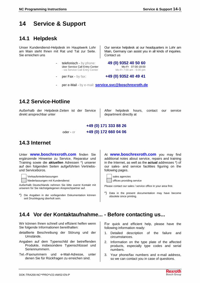
NC Programming Instructions Service & Support 14-1
DOK-TRA200-NC**PRO*V22-AW02-EN-P
14 Service & Support
14.1 Helpdesk
Unser Kundendienst-Helpdesk im Hauptwerk Lohram Main steht Ihnen mit Rat und Tat zur Seite.Sie erreichen uns
Our service helpdesk at our headquarters in Lohr amMain, Germany can assist you in all kinds of inquiries.Contact us
- telefonisch - by phone: 49 (0) 9352 40 50 60über Service Call Entry Center Mo-Fr 07:00-18:00- via Service Call Entry Center Mo-Fr 7:00 am - 6:00 pm
- per Fax - by fax: +49 (0) 9352 40 49 41
- per e-Mail - by e-mail: [email protected]
14.2 Service-Hotline
Außerhalb der Helpdesk-Zeiten ist der Servicedirekt ansprechbar unter
After helpdesk hours, contact our servicedepartment directly at
+49 (0) 171 333 88 26
oder - or +49 (0) 172 660 04 06
14.3 Internet
Unter www.boschrexroth.com finden Sieergänzende Hinweise zu Service, Reparatur undTraining sowie die aktuellen Adressen *) unsererauf den folgenden Seiten aufgeführten Vertriebs-und Servicebüros.
Verkaufsniederlassungen
Niederlassungen mit Kundendienst
Außerhalb Deutschlands nehmen Sie bitte zuerst Kontakt mitunserem für Sie nächstgelegenen Ansprechpartner auf.
*) Die Angaben in der vorliegenden Dokumentation könnenseit Drucklegung überholt sein.
At www.boschrexroth.com you may findadditional notes about service, repairs and trainingin the Internet, as well as the actual addresses *) ofour sales- and service facilities figuring on thefollowing pages.
sales agencies
offices providing service
Please contact our sales / service office in your area first.
*) Data in the present documentation may have becomeobsolete since printing.
14.4 Vor der Kontaktaufnahme... - Before contacting us...
Wir können Ihnen schnell und effizient helfen wennSie folgende Informationen bereithalten:
detaillierte Beschreibung der Störung und derUmstände.
Angaben auf dem Typenschild der betreffendenProdukte, insbesondere Typenschlüssel undSeriennummern.
Tel.-/Faxnummern und e-Mail-Adresse, unterdenen Sie für Rückfragen zu erreichen sind.
For quick and efficient help, please have thefollowing information ready:
1. Detailed description of the failure andcircumstances.
2. Information on the type plate of the affectedproducts, especially type codes and serialnumbers.
3. Your phone/fax numbers and e-mail address,so we can contact you in case of questions.
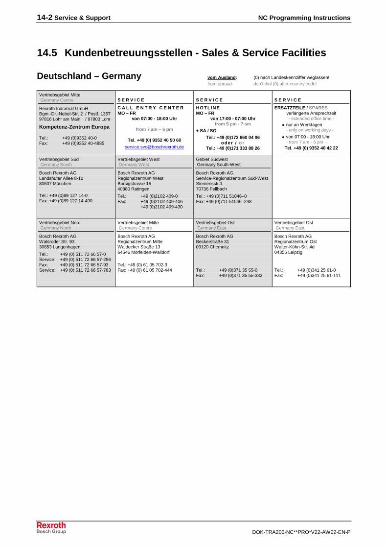
14-2 Service & Support NC Programming Instructions
DOK-TRA200-NC**PRO*V22-AW02-EN-P
14.5 Kundenbetreuungsstellen - Sales & Service Facilities
Deutschland – Germany vom Ausland: (0) nach Landeskennziffer weglassen!from abroad: don’t dial (0) after country code!
Vertriebsgebiet Mitte Germany Centre
Rexroth Indramat GmbHBgm.-Dr.-Nebel-Str. 2 / Postf. 135797816 Lohr am Main / 97803 Lohr
Kompetenz-Zentrum Europa
Tel.: +49 (0)9352 40-0Fax: +49 (0)9352 40-4885
S E R V I C E
C A L L E N T R Y C E N T E RMO – FR
von 07:00 - 18:00 Uhr
from 7 am – 6 pm
Tel. +49 (0) 9352 40 50 [email protected]
S E R V I C E
HOTLINEMO – FR
von 17:00 - 07:00 Uhrfrom 5 pm - 7 am
+ SA / SOTel.: +49 (0)172 660 04 06
oder / orTel.: +49 (0)171 333 88 26
S E R V I C E
ERSATZTEILE / SPARESverlängerte Ansprechzeit- extended office time -
♦ nur an Werktagen- only on working days -
♦ von 07:00 - 18:00 Uhr- from 7 am - 6 pm -
Tel. +49 (0) 9352 40 42 22
Vertriebsgebiet Süd Germany South
Bosch Rexroth AGLandshuter Allee 8-1080637 München
Tel.: +49 (0)89 127 14-0Fax: +49 (0)89 127 14-490
Vertriebsgebiet West Germany West
Bosch Rexroth AGRegionalzentrum WestBorsigstrasse 1540880 Ratingen
Tel.: +49 (0)2102 409-0Fax: +49 (0)2102 409-406
+49 (0)2102 409-430
Gebiet Südwest Germany South-West
Bosch Rexroth AGService-Regionalzentrum Süd-WestSiemensstr.170736 Fellbach
Tel.: +49 (0)711 51046–0Fax: +49 (0)711 51046–248
Vertriebsgebiet Nord Germany North
Bosch Rexroth AGWalsroder Str. 9330853 Langenhagen
Tel.: +49 (0) 511 72 66 57-0Service: +49 (0) 511 72 66 57-256Fax: +49 (0) 511 72 66 57-93Service: +49 (0) 511 72 66 57-783
Vertriebsgebiet Mitte Germany Centre
Bosch Rexroth AGRegionalzentrum MitteWaldecker Straße 1364546 Mörfelden-Walldorf
Tel.: +49 (0) 61 05 702-3Fax: +49 (0) 61 05 702-444
Vertriebsgebiet Ost Germany East
Bosch Rexroth AGBeckerstraße 3109120 Chemnitz
Tel.: +49 (0)371 35 55-0Fax: +49 (0)371 35 55-333
Vertriebsgebiet Ost Germany East
Bosch Rexroth AGRegionalzentrum OstWalter-Köhn-Str. 4d04356 Leipzig
Tel.: +49 (0)341 25 61-0Fax: +49 (0)341 25 61-111
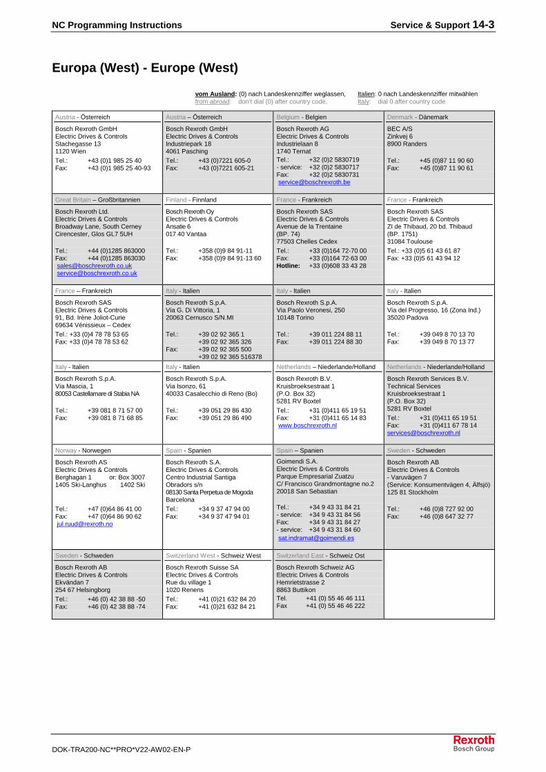
NC Programming Instructions Service & Support 14-3
DOK-TRA200-NC**PRO*V22-AW02-EN-P
Europa (West) - Europe (West)
vom Ausland: (0) nach Landeskennziffer weglassen, Italien: 0 nach Landeskennziffer mitwählenfrom abroad: don’t dial (0) after country code, Italy: dial 0 after country code
Austria - Österreich
Bosch Rexroth GmbHElectric Drives & ControlsStachegasse 131120 Wien
Tel.: +43 (0)1 985 25 40Fax: +43 (0)1 985 25 40-93
Austria – Österreich
Bosch Rexroth GmbHElectric Drives & ControlsIndustriepark 184061 Pasching
Tel.: +43 (0)7221 605-0Fax: +43 (0)7221 605-21
Belgium - Belgien
Bosch Rexroth AGElectric Drives & ControlsIndustrielaan 81740 TernatTel.: +32 (0)2 5830719- service: +32 (0)2 5830717Fax: +32 (0)2 5830731 [email protected]
Denmark - Dänemark
BEC A/SZinkvej 68900 Randers
Tel.: +45 (0)87 11 90 60Fax: +45 (0)87 11 90 61
Great Britain – Großbritannien
Bosch Rexroth Ltd.Electric Drives & ControlsBroadway Lane, South CerneyCirencester, Glos GL7 5UH
Tel.: +44 (0)1285 863000Fax: +44 (0)1285 863030 [email protected] [email protected]
Finland - Finnland
Bosch Rexroth OyElectric Drives & ControlsAnsatie 6017 40 Vantaa
Tel.: +358 (0)9 84 91-11Fax: +358 (0)9 84 91-13 60
France - Frankreich
Bosch Rexroth SASElectric Drives & ControlsAvenue de la Trentaine(BP. 74)77503 Chelles Cedex
Tel.: +33 (0)164 72-70 00Fax: +33 (0)164 72-63 00Hotline: +33 (0)608 33 43 28
France - Frankreich
Bosch Rexroth SASElectric Drives & ControlsZI de Thibaud, 20 bd. Thibaud(BP. 1751)31084 Toulouse
Tel.: +33 (0)5 61 43 61 87Fax: +33 (0)5 61 43 94 12
France – Frankreich
Bosch Rexroth SASElectric Drives & Controls91, Bd. Irène Joliot-Curie69634 Vénissieux – Cedex
Tel.: +33 (0)4 78 78 53 65Fax: +33 (0)4 78 78 53 62
Italy - Italien
Bosch Rexroth S.p.A.Via G. Di Vittoria, 120063 Cernusco S/N.MI
Tel.: +39 02 92 365 1+39 02 92 365 326
Fax: +39 02 92 365 500+39 02 92 365 516378
Italy - Italien
Bosch Rexroth S.p.A.Via Paolo Veronesi, 25010148 Torino
Tel.: +39 011 224 88 11Fax: +39 011 224 88 30
Italy - Italien
Bosch Rexroth S.p.A.Via del Progresso, 16 (Zona Ind.)35020 Padova
Tel.: +39 049 8 70 13 70Fax: +39 049 8 70 13 77
Italy - Italien
Bosch Rexroth S.p.A.Via Mascia, 180053 Castellamare di Stabia NA
Tel.: +39 081 8 71 57 00Fax: +39 081 8 71 68 85
Italy - Italien
Bosch Rexroth S.p.A.Via Isonzo, 6140033 Casalecchio di Reno (Bo)
Tel.: +39 051 29 86 430Fax: +39 051 29 86 490
Netherlands – Niederlande/Holland
Bosch Rexroth B.V.Kruisbroeksestraat 1(P.O. Box 32)5281 RV Boxtel
Tel.: +31 (0)411 65 19 51Fax: +31 (0)411 65 14 83 www.boschrexroth.nl
Netherlands - Niederlande/Holland
Bosch Rexroth Services B.V.Technical ServicesKruisbroeksestraat 1(P.O. Box 32)5281 RV Boxtel
Tel.: +31 (0)411 65 19 51Fax: +31 (0)411 67 78 [email protected]
Norway - Norwegen
Bosch Rexroth ASElectric Drives & ControlsBerghagan 1 or: Box 30071405 Ski-Langhus 1402 Ski
Tel.: +47 (0)64 86 41 00Fax: +47 (0)64 86 90 62 [email protected]
Spain - Spanien
Bosch Rexroth S.A.Electric Drives & ControlsCentro Industrial SantigaObradors s/n08130 Santa Perpetua de MogodaBarcelona
Tel.: +34 9 37 47 94 00Fax: +34 9 37 47 94 01
Spain – Spanien
Goimendi S.A.Electric Drives & ControlsParque Empresarial ZuatzuC/ Francisco Grandmontagne no.220018 San Sebastian
Tel.: +34 9 43 31 84 21- service: +34 9 43 31 84 56Fax: +34 9 43 31 84 27- service: +34 9 43 31 84 60 [email protected]
Sweden - Schweden
Bosch Rexroth ABElectric Drives & Controls- Varuvägen 7(Service: Konsumentvägen 4, Älfsjö)125 81 Stockholm
Tel.: +46 (0)8 727 92 00Fax: +46 (0)8 647 32 77
Sweden - Schweden
Bosch Rexroth ABElectric Drives & ControlsEkvändan 7254 67 Helsingborg
Tel.: +46 (0) 42 38 88 -50Fax: +46 (0) 42 38 88 -74
Switzerland West - Schweiz West
Bosch Rexroth Suisse SAElectric Drives & ControlsRue du village 11020 Renens
Tel.: +41 (0)21 632 84 20Fax: +41 (0)21 632 84 21
Switzerland East - Schweiz Ost
Bosch Rexroth Schweiz AGElectric Drives & ControlsHemrietstrasse 28863 ButtikonTel. +41 (0) 55 46 46 111Fax +41 (0) 55 46 46 222
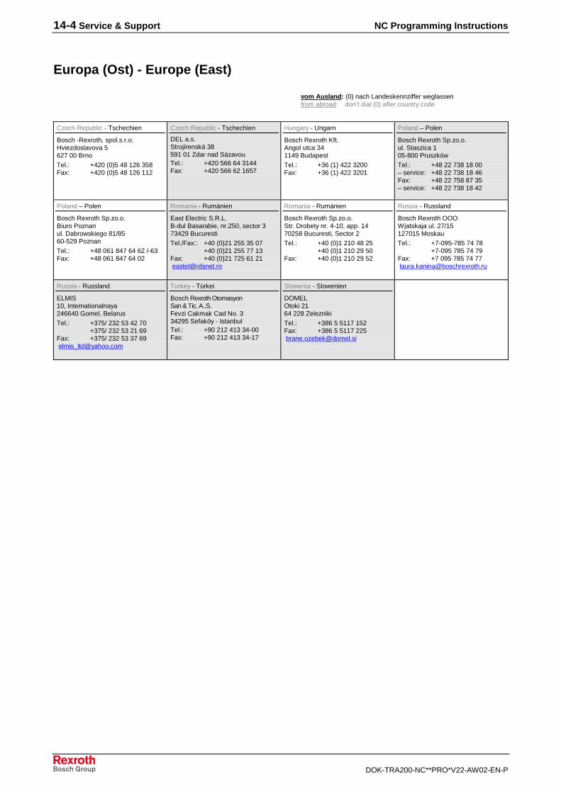
14-4 Service & Support NC Programming Instructions
DOK-TRA200-NC**PRO*V22-AW02-EN-P
Europa (Ost) - Europe (East)
vom Ausland: (0) nach Landeskennziffer weglassen
from abroad: don’t dial (0) after country code
Czech Republic - Tschechien
Bosch -Rexroth, spol.s.r.o.Hviezdoslavova 5627 00 Brno
Tel.: +420 (0)5 48 126 358Fax: +420 (0)5 48 126 112
Czech Republic - Tschechien
DEL a.s.Strojírenská 38591 01 Zdar nad SázavouTel.: +420 566 64 3144Fax: +420 566 62 1657
Hungary - Ungarn
Bosch Rexroth Kft.Angol utca 341149 Budapest
Tel.: +36 (1) 422 3200Fax: +36 (1) 422 3201
Poland – Polen
Bosch Rexroth Sp.zo.o.ul. Staszica 105-800 Pruszków
Tel.: +48 22 738 18 00– service: +48 22 738 18 46Fax: +48 22 758 87 35– service: +48 22 738 18 42
Poland – Polen
Bosch Rexroth Sp.zo.o.Biuro Poznanul. Dabrowskiego 81/8560-529 Poznan
Tel.: +48 061 847 64 62 /-63Fax: +48 061 847 64 02
Romania - Rumänien
East Electric S.R.L.B-dul Basarabie, nr.250, sector 373429 Bucuresti
Tel./Fax:: +40 (0)21 255 35 07+40 (0)21 255 77 13
Fax: +40 (0)21 725 61 21 [email protected]
Romania - Rumänien
Bosch Rexroth Sp.zo.o.Str. Drobety nr. 4-10, app. 1470258 Bucuresti, Sector 2
Tel.: +40 (0)1 210 48 25+40 (0)1 210 29 50
Fax: +40 (0)1 210 29 52
Russia - Russland
Bosch Rexroth OOOWjatskaja ul. 27/15127015 Moskau
Tel.: +7-095-785 74 78+7-095 785 74 79
Fax: +7 095 785 74 77 [email protected]
Russia - Russland
ELMIS10, Internationalnaya246640 Gomel, Belarus
Tel.: +375/ 232 53 42 70+375/ 232 53 21 69
Fax: +375/ 232 53 37 69 [email protected]
Turkey - Türkei
Bosch Rexroth OtomasyonSan & Tic. A..S.Fevzi Cakmak Cad No. 334295 Sefaköy - IstanbulTel.: +90 212 413 34-00Fax: +90 212 413 34-17
Slowenia - Slowenien
DOMELOtoki 2164 228 Zelezniki
Tel.: +386 5 5117 152Fax: +386 5 5117 225 [email protected]
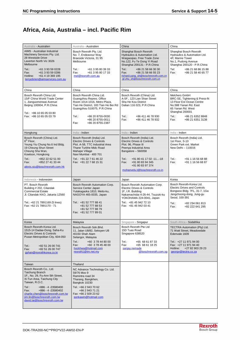
NC Programming Instructions Service & Support 14-5
DOK-TRA200-NC**PRO*V22-AW02-EN-P
Africa, Asia, Australia – incl. Pacific Rim
Australia - Australien
AIMS - Australian IndustrialMachinery Services Pty. Ltd.28 Westside DriveLaverton North Vic 3026Melbourne
Tel.: +61 3 93 59 0228Fax: +61 3 93 59 0286Hotline: +61 4 19 369 195 [email protected]
Australia - Australien
Bosch Rexroth Pty. Ltd.No. 7, Endeavour WayBraeside Victoria, 31 95Melbourne
Tel.: +61 3 95 80 39 33Fax: +61 3 95 80 17 33 [email protected]
China
Shanghai Bosch RexrothHydraulics & Automation Ltd.Waigaoqiao, Free Trade ZoneNo.122, Fu Te Dong Yi RoadShanghai 200131 - P.R.China
Tel.: +86 21 58 66 30 30Fax: +86 21 58 66 55 [email protected] [email protected]
China
Shanghai Bosch RexrothHydraulics & Automation Ltd.4/f, Marine TowerNo.1, Pudong AvenueShanghai 200120 - P.R.China
Tel: +86 21 68 86 15 88Fax: +86 21 58 40 65 77
China
Bosch Rexroth China Ltd.15/F China World Trade Center1, Jianguomenwai AvenueBeijing 100004, P.R.China
Tel.: +86 10 65 05 03 80Fax: +86 10 65 05 03 79
China
Bosch Rexroth China Ltd.Guangzhou Repres. OfficeRoom 1014-1016, Metro Plaza,Tian He District, 183 Tian He Bei RdGuangzhou 510075, P.R.China
Tel.: +86 20 8755-0030+86 20 8755-0011
Fax: +86 20 8755-2387
China
Bosch Rexroth (China) Ltd.A-5F., 123 Lian Shan StreetSha He Kou DistrictDalian 116 023, P.R.China
Tel.: +86 411 46 78 930Fax: +86 411 46 78 932
China
Melchers GmbHBRC-SE, Tightening & Press-fit13 Floor Est Ocean CentreNo.588 Yanan Rd. East65 Yanan Rd. WestShanghai 200001
Tel.: +86 21 6352 8848Fax: +86 21 6351 3138
Hongkong
Bosch Rexroth (China) Ltd.6th
Floor,Yeung Yiu Chung No.6 Ind Bldg.19 Cheung Shun StreetCheung Sha Wan,Kowloon, Hongkong
Tel.: +852 22 62 51 00Fax: +852 27 41 33 44
India - Indien
Bosch Rexroth (India) Ltd.Electric Drives & ControlsPlot. A-58, TTC Industrial AreaThane Turbhe Midc RoadMahape VillageNavi Mumbai - 400 701
Tel.: +91 22 7 61 46 22Fax: +91 22 7 68 15 31
India - Indien
Bosch Rexroth (India) Ltd.Electric Drives & ControlsPlot. 96, Phase IIIPeenya Industrial AreaBangalore – 560058
Tel.: +91 80 41 17 02 -11...-18Fax: +91 80 83 94 345
+91 80 83 97 374
India - Indien
Bosch Rexroth (India) Ltd.1st Floor, S-10Green Park ext. MarketNew Delhi – 110016
Tel.: +91 1 16 56 68 88Fax: +91 1 16 56 68 87
Indonesia - Indonesien
PT. Bosch RexrothBuilding # 202, CilandakCommercial EstateJl. Cilandak KKO, Jakarta 12560
Tel.: +62 21 7891169 (5 lines)Fax: +62 21 7891170 - 71
Japan
Bosch Rexroth Automation Corp.Service Center JapanYutakagaoka 1810, Meito-ku,NAGOYA 465-0035, Japan
Tel.: +81 52 777 88 41+81 52 777 88 53+81 52 777 88 79
Fax: +81 52 777 89 01
Japan
Bosch Rexroth Automation Corp.Electric Drives & Controls1F, I.R. BuildingNakamachidai 4-26-44, Tsuzuki-kuYOKOHAMA 224-0041, Japan
Tel.: +81 45 942 72 10Fax: +81 45 942 03 41
Korea
Bosch Rexroth-Korea Ltd.Electric Drives and ControlsBongwoo Bldg. 7FL, 31-7, 1GaJangchoong-dong, Jung-guSeoul, 100-391
Tel.: +82 234 061 813Fax: +82 222 641 295
Korea
Bosch Rexroth-Korea Ltd.1515-14 Dadae-Dong, Saha-KuElectric Drives & ControlsPusan Metropolitan City, 604-050
Tel.: +82 51 26 00 741Fax: +82 51 26 00 747 [email protected]
Malaysia
Bosch Rexroth Sdn.Bhd.11, Jalan U8/82, Seksyen U840150 Shah AlamSelangor, Malaysia
Tel.: +60 3 78 44 80 00Fax: +60 3 78 45 48 00 [email protected] [email protected]
Singapore - Singapur
Bosch Rexroth Pte Ltd15D Tuas RoadSingapore 638520
Tel.: +65 68 61 87 33Fax: +65 68 61 18 25 sanjay.nemade
@boschrexroth.com.sg
South Africa - Südafrika
TECTRA Automation (Pty) Ltd.71 Watt Street, MeadowdaleEdenvale 1609
Tel.: +27 11 971 94 00Fax: +27 11 971 94 40Hotline: +27 82 903 29 23 [email protected]
Taiwan
Bosch Rexroth Co., Ltd.Taichung Branch1F., No. 29, Fu-Ann 5th Street,Xi-Tun Area, Taichung CityTaiwan, R.O.C.
Tel : +886 - 4 -23580400Fax: +886 - 4 [email protected]@[email protected]
Thailand
NC Advance Technology Co. Ltd.59/76 Moo 9Ramintra road 34Tharang, Bangkhen,Bangkok 10230
Tel.: +66 2 943 70 62 +66 2 943 71 21Fax: +66 2 509 23 62 [email protected]
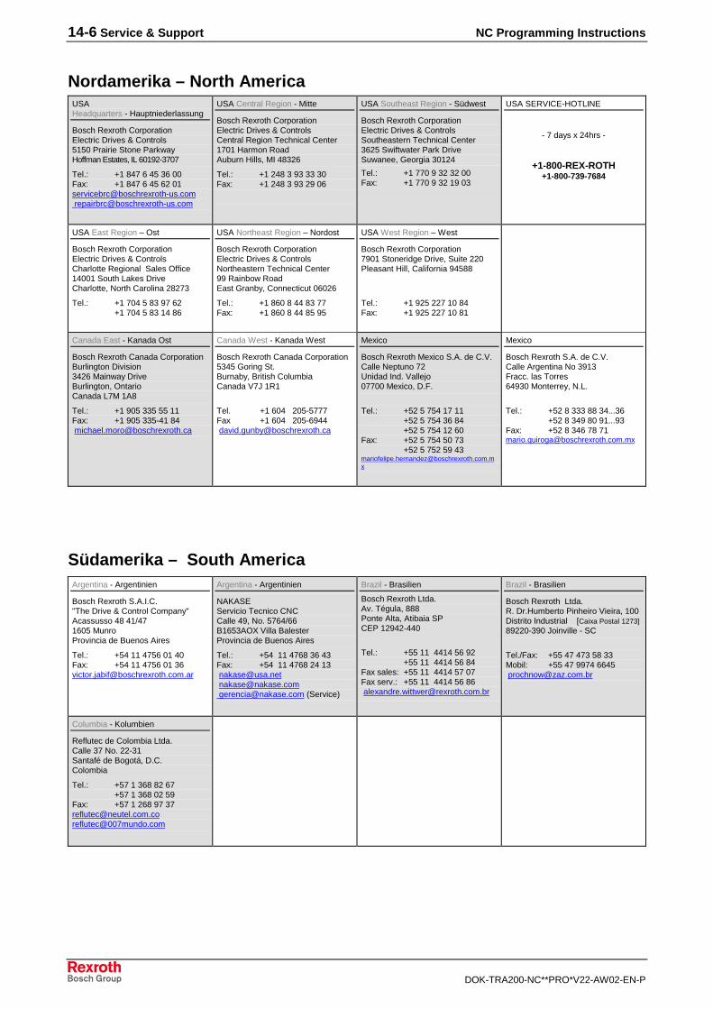
14-6 Service & Support NC Programming Instructions
DOK-TRA200-NC**PRO*V22-AW02-EN-P
Nordamerika – North AmericaUSAHeadquarters - Hauptniederlassung
Bosch Rexroth CorporationElectric Drives & Controls5150 Prairie Stone ParkwayHoffman Estates, IL 60192-3707
Tel.: +1 847 6 45 36 00Fax: +1 847 6 45 62 [email protected] [email protected]
USA Central Region - Mitte
Bosch Rexroth CorporationElectric Drives & ControlsCentral Region Technical Center1701 Harmon RoadAuburn Hills, MI 48326
Tel.: +1 248 3 93 33 30Fax: +1 248 3 93 29 06
USA Southeast Region - Südwest
Bosch Rexroth CorporationElectric Drives & ControlsSoutheastern Technical Center3625 Swiftwater Park DriveSuwanee, Georgia 30124
Tel.: +1 770 9 32 32 00Fax: +1 770 9 32 19 03
USA SERVICE-HOTLINE
- 7 days x 24hrs -
+1-800-REX-ROTH+1-800-739-7684
USA East Region – Ost
Bosch Rexroth CorporationElectric Drives & ControlsCharlotte Regional Sales Office14001 South Lakes DriveCharlotte, North Carolina 28273
Tel.: +1 704 5 83 97 62+1 704 5 83 14 86
USA Northeast Region – Nordost
Bosch Rexroth CorporationElectric Drives & ControlsNortheastern Technical Center99 Rainbow RoadEast Granby, Connecticut 06026
Tel.: +1 860 8 44 83 77Fax: +1 860 8 44 85 95
USA West Region – West
Bosch Rexroth Corporation7901 Stoneridge Drive, Suite 220Pleasant Hill, California 94588
Tel.: +1 925 227 10 84Fax: +1 925 227 10 81
Canada East - Kanada Ost
Bosch Rexroth Canada CorporationBurlington Division3426 Mainway DriveBurlington, OntarioCanada L7M 1A8
Tel.: +1 905 335 55 11Fax: +1 905 335-41 84 [email protected]
Canada West - Kanada West
Bosch Rexroth Canada Corporation5345 Goring St.Burnaby, British ColumbiaCanada V7J 1R1
Tel. +1 604 205-5777Fax +1 604 205-6944 [email protected]
Mexico
Bosch Rexroth Mexico S.A. de C.V.Calle Neptuno 72Unidad Ind. Vallejo07700 Mexico, D.F.
Tel.: +52 5 754 17 11+52 5 754 36 84+52 5 754 12 60
Fax: +52 5 754 50 73+52 5 752 59 43
Mexico
Bosch Rexroth S.A. de C.V.Calle Argentina No 3913Fracc. las Torres64930 Monterrey, N.L.
Tel.: +52 8 333 88 34...36+52 8 349 80 91...93
Fax: +52 8 346 78 [email protected]
Südamerika – South AmericaArgentina - Argentinien
Bosch Rexroth S.A.I.C."The Drive & Control Company"Acassusso 48 41/471605 MunroProvincia de Buenos Aires
Tel.: +54 11 4756 01 40Fax: +54 11 4756 01 [email protected]
Argentina - Argentinien
NAKASEServicio Tecnico CNCCalle 49, No. 5764/66B1653AOX Villa BalesterProvincia de Buenos Aires
Tel.: +54 11 4768 36 43Fax: +54 11 4768 24 13 [email protected] [email protected] [email protected] (Service)
Brazil - Brasilien
Bosch Rexroth Ltda.Av. Tégula, 888Ponte Alta, Atibaia SPCEP 12942-440
Tel.: +55 11 4414 56 92+55 11 4414 56 84
Fax sales: +55 11 4414 57 07Fax serv.: +55 11 4414 56 86 [email protected]
Brazil - Brasilien
Bosch Rexroth Ltda.R. Dr.Humberto Pinheiro Vieira, 100Distrito Industrial [Caixa Postal 1273]89220-390 Joinville - SC
Tel./Fax: +55 47 473 58 33Mobil: +55 47 9974 6645 [email protected]
Columbia - Kolumbien
Reflutec de Colombia Ltda.Calle 37 No. 22-31Santafé de Bogotá, D.C.Colombia
Tel.: +57 1 368 82 67+57 1 368 02 59
Fax: +57 1 268 97 [email protected]@007mundo.com
NC Programming Instructions
DOK-TRA200-NC**PRO*V22-AW02-EN-P
Notes

Bosch Rexroth AGElectric Drives and ControlsBgm.-Dr.-Nebel-Str. 297816 Lohr a. Main, [email protected]
Printed in GermanyDOK-TRA200-NC**PRO*V22-AW02-EN-P295379