Rexroth MTC200/ISP200/TRANS200 Edition 01 MTGUI … · Rexroth MTC200/ISP200/TRANS200 MTGUI User...
62
298459 Edition 01 Rexroth MTC200/ISP200/TRANS200 MTGUI User Interface Application Manual Industrial Hydraulics Electric Drives and Controls Linear Motion and Assembly Technologies Pneumatics Service Automation Mobile Hydraulics
-
Upload
truongdang -
Category
Documents
-
view
218 -
download
0
Transcript of Rexroth MTC200/ISP200/TRANS200 Edition 01 MTGUI … · Rexroth MTC200/ISP200/TRANS200 MTGUI User...

298459Edition 01
RexrothMTC200/ISP200/TRANS200MTGUI User Interface
Application Manual
IndustrialHydraulics
Electric Drivesand Controls
Linear Motion andAssembly Technologies Pneumatics
ServiceAutomation
MobileHydraulics
About this Documentation MTGUI User Interface
DOK-CONTRL-MTGUI***V23-AW01-EN-P
Rexroth MTC200/ISP200/TRANS200
MTGUI User Interface
Application Manual
DOK-CONTRL-MTGUI***V23-AW01-EN-P
Document Number 120-0401-B309-01/EN
This documentation provides an overview of operating the user interfacefor machine tools and describes the menues.
Description ReleaseDate
Notes
120-0401-B309-01/EN 09.2003 Valid from version 23
� 2003 Bosch Rexroth AG
Copying this document, giving it to others and the use or communicationof the contents thereof without express authority, are forbidden. Offendersare liable for the payment of damages. All rights are reserved in the eventof the grant of a patent or the registration of a utility model or design(DIN 34-1).
The specified data is for product description purposes only and may notbe deemed to be guaranteed unless expressly confirmed in the contract.All rights are reserved with respect to the content of this documentationand the availability of the product.
Bosch Rexroth AGBgm.-Dr.-Nebel-Str. 2 • D-97816 Lohr a. Main
Telephone +49 (0)93 52/40-0 • Tx 68 94 21 • Fax +49 (0)93 52/40-48 85
http://www.boschrexroth.com/
Dept. BRC/ESM2 (HG)
Dept. BRC/ESM6 (DiHa)
This document has been printed on chlorine-free bleached paper.
Title
Type of Documentation
Document Typecode
Internal File Reference
Purpose of Documentation
Record of Revisions
Copyright
Validity
Published by
Note

MTGUI User Interface Contents I
DOK-CONTRL-MTGUI***V23-AW01-EN-P
Contents
1 Overview of Machine Tool Graphic User Interfaces 1-1
1.1 Abbreviations Used....................................................................................................................... 1-1
1.2 General Information About the MTGUI System ............................................................................ 1-1
Bosch Rexroth Control Systems with MTGUI.......................................................................... 1-1
Characteristics of the MTGUI System ..................................................................................... 1-2
Concept of MT Interfaces......................................................................................................... 1-2
Application Areas for MT Interfaces (MTC200) ....................................................................... 1-4
Operating Philosophy............................................................................................................... 1-4
Screen Layout .......................................................................................................................... 1-5
Supported Monitor Resolutions ............................................................................................... 1-6
Main Menu ............................................................................................................................... 1-7
Single and Multiple Window Operation.................................................................................... 1-9
1.3 Starting the MT Interface ............................................................................................................ 1-10
Start for MTC200 ................................................................................................................... 1-10
Start for TRANS200 ............................................................................................................... 1-11
1.4 Calling Functions......................................................................................................................... 1-12
1.5 Standard Operation of the MTGUI Desktop................................................................................ 1-14
1.6 System Error Display .................................................................................................................. 1-16
1.7 Header ........................................................................................................................................ 1-18
1.8 Offline Operation ......................................................................................................................... 1-20
1.9 Language Switching.................................................................................................................... 1-20
1.10 Connection Interruption............................................................................................................... 1-20
2 Applications in the MT Interface 2-1
2.1 MTGUI Desktop ............................................................................................................................ 2-1
Main Menu (MTC200) .............................................................................................................. 2-1
Main Menu (TRANS200).......................................................................................................... 2-2
Control Selection (MTC200) .................................................................................................... 2-3
Control Selection (TRANS200) ................................................................................................ 2-6
Project Navigator ..................................................................................................................... 2-6
NC Screen................................................................................................................................ 2-7
Setup Menu.............................................................................................................................. 2-7
2.2 WinHMI Desktop (MTC200 Only) ............................................................................................... 2-10
2.3 WinPCL Desktop (MTC200 Only) ............................................................................................... 2-11
2.4 DriveTop Desktop ....................................................................................................................... 2-11
3 Navigating in the MT Interface 3-1
3.1 Desktop Selection from the Main Menu (MTC200)....................................................................... 3-1
II Contents MTGUI User Interface
DOK-CONTRL-MTGUI***V23-AW01-EN-P
3.2 Changing Desktops Using Project Navigator................................................................................ 3-2
3.3 Navigating Within the MTGUI Desktop ......................................................................................... 3-3
4 Project Navigator 4-1
4.1 General Information About Project Navigator ............................................................................... 4-1
Instances.................................................................................................................................. 4-1
Call and Exit ............................................................................................................................. 4-2
Views........................................................................................................................................ 4-2
Control Unit-Specific Representation....................................................................................... 4-6
Offline Operation...................................................................................................................... 4-7
4.2 Operation ...................................................................................................................................... 4-7
Switching Between Tree and List ............................................................................................ 4-8
Navigation in the Tree.............................................................................................................. 4-8
Navigation in the List................................................................................................................ 4-9
5 Index 5-1
6 Service & Support 6-1
6.1 Helpdesk ....................................................................................................................................... 6-1
6.2 Service-Hotline.............................................................................................................................. 6-1
6.3 Internet .......................................................................................................................................... 6-1
6.4 Vor der Kontaktaufnahme... - Before contacting us...................................................................... 6-1
6.5 Kundenbetreuungsstellen - Sales & Service Facilities ................................................................. 6-2

MTGUI User Interface Overview of Machine Tool Graphic User Interfaces 1-1
DOK-CONTRL-MTGUI***V23-AW01-EN-P
1 Overview of Machine Tool Graphic User Interfaces
1.1 Abbreviations Used
In addition to product names and system designations, the abbreviationslisted below are used in this documentation.
Abbreviation Explanation
TM Tool Machine
MTGUI Machine Tool Graphical User Interface
M keys Configurable machine keys
F keys Configurable function keys
Fig. 1-1: Abbreviations used
1.2 General Information About the MTGUI System
Bosch Rexroth MT interfaces (MTGUI = Machine Tool Graphic UserInterface) enable users of machine tools and transfer machines to:
• operate
• configure
• parameterize and to
• program.
Bosch Rexroth Control Systems with MTGUIBosch Rexroth control systems, such as
• MTC200
• ISP200
• TRANS200 and
• MTA200
can be uniformly configured and operated to a great extent with theMTGUI.

1-2 Overview of Machine Tool Graphic User Interfaces MTGUI User Interface
DOK-CONTRL-MTGUI***V23-AW01-EN-P
MTGUIAnw_gr.bmp
Fig. 1-2: Bosch Rexroth control systems
Characteristics of the MTGUI System• Standard user interface, standard configuration tool (look & feel) with
simple and comprehensive keyboard operation
• Use of Windows as the global standard for PC systems
• Configurable interface
• Integration of external components (open interfaces, 3rd partysoftware)
• Operating system platforms: WinNT, Windows2000, (Win95/Win98)
• Modularization to create project-specific interface versions atapplication level
• Standard user interface, even in a heterogeneous productionenvironment
• Up-to-date Windows concepts for editing and commissioning
• Support of distributed systems (network of PCs)
• Multilingual user text (e.g. program comments)
• Reduced application, service and training costs
Thanks to the standard MT interface, the user can quickly learn how tooperate various Bosch Rexroth controls.
Concept of MT InterfacesThe MTGUI system contains subdomains for the expansion of an MTinterface, which enables the applications for the MTGUI system to run invarious desktops.
The modular character of the application software means that variouscontrol systems can be combined.
At the maximum expansion level of the MTGUI system, applications canbe run with four desktops.
Advantage
MTGUI User Interface Overview of Machine Tool Graphic User Interfaces 1-3
DOK-CONTRL-MTGUI***V23-AW01-EN-P
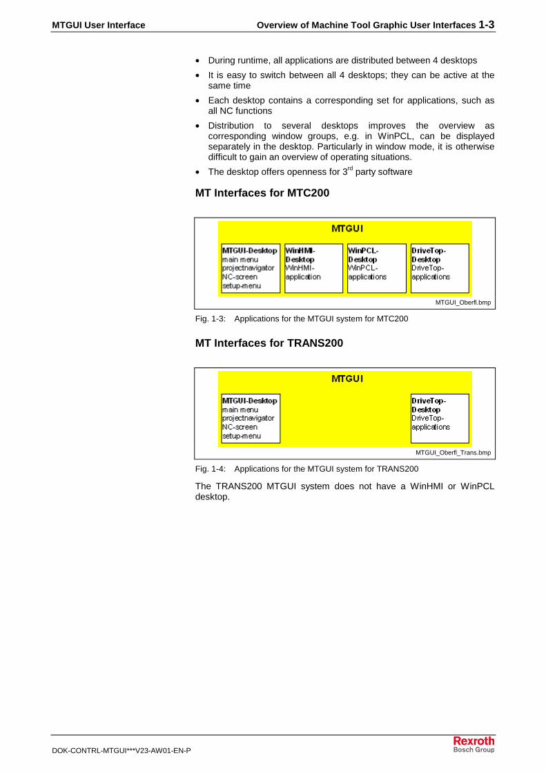
• During runtime, all applications are distributed between 4 desktops
• It is easy to switch between all 4 desktops; they can be active at thesame time
• Each desktop contains a corresponding set for applications, such asall NC functions
• Distribution to several desktops improves the overview ascorresponding window groups, e.g. in WinPCL, can be displayedseparately in the desktop. Particularly in window mode, it is otherwisedifficult to gain an overview of operating situations.
• The desktop offers openness for 3rd party software
MT Interfaces for MTC200
MTGUI_Oberfl.bmp
Fig. 1-3: Applications for the MTGUI system for MTC200
MT Interfaces for TRANS200
MTGUI_Oberfl_Trans.bmp
Fig. 1-4: Applications for the MTGUI system for TRANS200
The TRANS200 MTGUI system does not have a WinHMI or WinPCLdesktop.

1-4 Overview of Machine Tool Graphic User Interfaces MTGUI User Interface
DOK-CONTRL-MTGUI***V23-AW01-EN-P
Application Areas for MT Interfaces (MTC200)
MTGUIDesktops_gr.bmp
(1): WinMTC, see chapt. "MTGUI Desktop"(2): WinHMI, see chapt. "WinHMI Desktop (MTC200 Only)"(3): WinPLC, see chapt. "WinPCL Desktop (MTC200 Only)"(4): Project Navigator, see chapt. "General Information About Project
Navigator"(5): Drive Top, see chapt. "DriveTop Desktop"
Fig. 1-5: Examples of desktops in the MTGUI system for MTC200
Operating PhilosophyThe operation of MT interfaces in the MTGUI system offers the followingfeatures:
• Global use of keys on all desktops (does not apply to TRANS200,which does not have any <OP> keys)The <OP> keys for WinHMI can also be used in the MTGUI desktop.This means that WinHMI applications can be started from the MTGUIdesktop.
• Desktop operation via function keys
• Menu bars in the desktops
• Pop-up menus for quickly selecting menu commands
MTGUI User Interface Overview of Machine Tool Graphic User Interfaces 1-5
DOK-CONTRL-MTGUI***V23-AW01-EN-P
• Global user management
• Operational support from a help system
• Access to applications via main menu
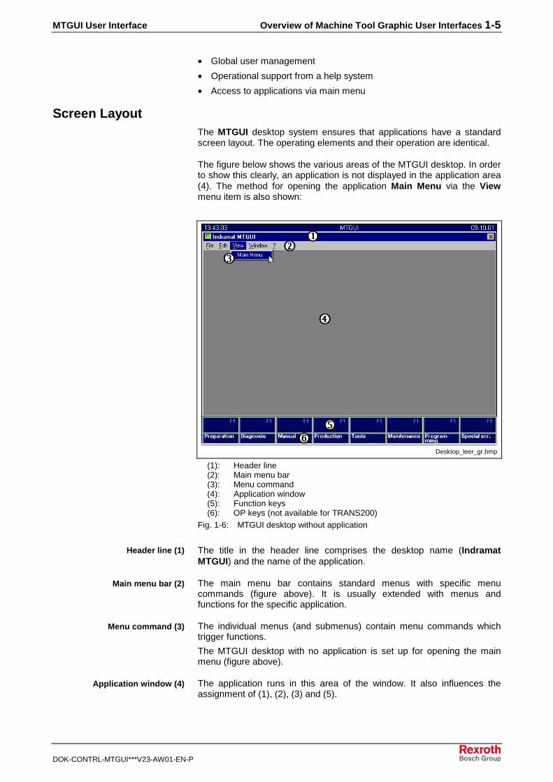
Screen LayoutThe MTGUI desktop system ensures that applications have a standardscreen layout. The operating elements and their operation are identical.
The figure below shows the various areas of the MTGUI desktop. In orderto show this clearly, an application is not displayed in the application area(4). The method for opening the application Main Menu via the Viewmenu item is also shown:
Desktop_leer_gr.bmp
(1): Header line(2): Main menu bar(3): Menu command(4): Application window(5): Function keys(6): OP keys (not available for TRANS200)
Fig. 1-6: MTGUI desktop without application
The title in the header line comprises the desktop name (IndramatMTGUI) and the name of the application.
The main menu bar contains standard menus with specific menucommands (figure above). It is usually extended with menus andfunctions for the specific application.
The individual menus (and submenus) contain menu commands whichtrigger functions.
The MTGUI desktop with no application is set up for opening the mainmenu (figure above).
The application runs in this area of the window. It also influences theassignment of (1), (2), (3) and (5).
Header line (1)
Main menu bar (2)
Menu command (3)
Application window (4)
1-6 Overview of Machine Tool Graphic User Interfaces MTGUI User Interface
DOK-CONTRL-MTGUI***V23-AW01-EN-P
Function keys <F2> - <F9> are used by the dialog windows of the activeapplication. They are used to execute functions in the application. In an"empty" desktop, the keys do not have a function and are not labeled(except <F1>, see figure above).
The availability of the OP keys depends on the control unit type used. TheTRANS200 control does not have any <OP> keys.
If WinHMI is installed on the control unit, the <OP> keys are linked toWinHMI applications. It is possible to switch from applications in theMTGUI desktop to WinHMI applications.
The <OP8> key (Programming) has a navigator function.
If an application in the HMI desktop is active, you can switch to the mainmenu of the MTGUI desktop by pressing the <OP8> key.
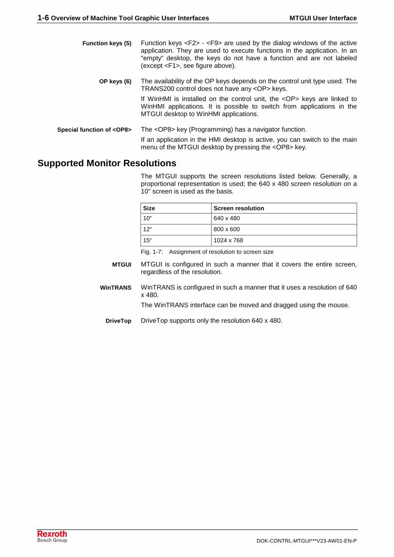
Supported Monitor ResolutionsThe MTGUI supports the screen resolutions listed below. Generally, aproportional representation is used; the 640 x 480 screen resolution on a10" screen is used as the basis.
Size Screen resolution
10“ 640 x 480
12“ 800 x 600
15“ 1024 x 768
Fig. 1-7: Assignment of resolution to screen size
MTGUI is configured in such a manner that it covers the entire screen,regardless of the resolution.
WinTRANS is configured in such a manner that it uses a resolution of 640x 480.
The WinTRANS interface can be moved and dragged using the mouse.
DriveTop supports only the resolution 640 x 480.
Function keys (5)
OP keys (6)
Special function of <OP8>
MTGUI
WinTRANS
DriveTop
MTGUI User Interface Overview of Machine Tool Graphic User Interfaces 1-7
DOK-CONTRL-MTGUI***V23-AW01-EN-P
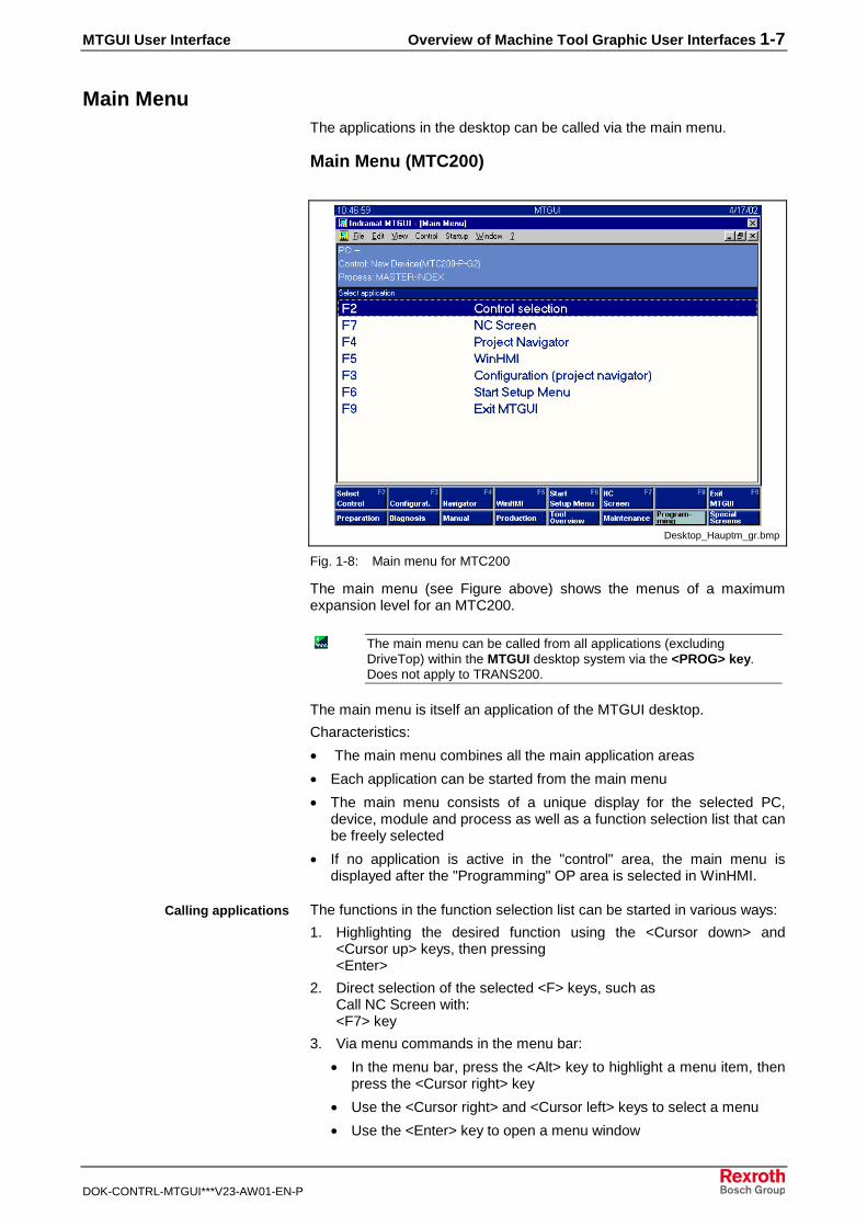
Main MenuThe applications in the desktop can be called via the main menu.
Main Menu (MTC200)
Desktop_Hauptm_gr.bmp
Fig. 1-8: Main menu for MTC200
The main menu (see Figure above) shows the menus of a maximumexpansion level for an MTC200.
The main menu can be called from all applications (excludingDriveTop) within the MTGUI desktop system via the <PROG> key. Does not apply to TRANS200.
The main menu is itself an application of the MTGUI desktop.
Characteristics:
• The main menu combines all the main application areas
• Each application can be started from the main menu
• The main menu consists of a unique display for the selected PC,device, module and process as well as a function selection list that canbe freely selected
• If no application is active in the "control" area, the main menu isdisplayed after the "Programming" OP area is selected in WinHMI.
The functions in the function selection list can be started in various ways:
1. Highlighting the desired function using the <Cursor down> and<Cursor up> keys, then pressing<Enter>
2. Direct selection of the selected <F> keys, such as Call NC Screen with:<F7> key
3. Via menu commands in the menu bar:
• In the menu bar, press the <Alt> key to highlight a menu item, thenpress the <Cursor right> key
• Use the <Cursor right> and <Cursor left> keys to select a menu
• Use the <Enter> key to open a menu window
Calling applications

1-8 Overview of Machine Tool Graphic User Interfaces MTGUI User Interface
DOK-CONTRL-MTGUI***V23-AW01-EN-P
• Select a menu command with the <Cursor down> and <Cursor up>keys
• Press <Enter> to start the menu command
Main Menu (TRANS200)
Hauptmenu_Trans_gr.bmp
Fig. 1-9: Main menu for TRANS200
The functions in the function selection list can be started in various ways:
1. Direct selection of the selected <F> keys, such as Call NC Screen with:<F5> key
2. Via menu commands in the menu bar:
• In the menu bar, press the <Alt> key to highlight a menu item, thenpress the <Cursor right> key
• Use the <Cursor right> and <Cursor left> keys to select a menu
• Use the <Enter> key to open a menu window
• Select a menu command with the <Cursor down> and <Cursor up>keys
• Press <Enter> to start the menu command
Calling applications
MTGUI User Interface Overview of Machine Tool Graphic User Interfaces 1-9
DOK-CONTRL-MTGUI***V23-AW01-EN-P
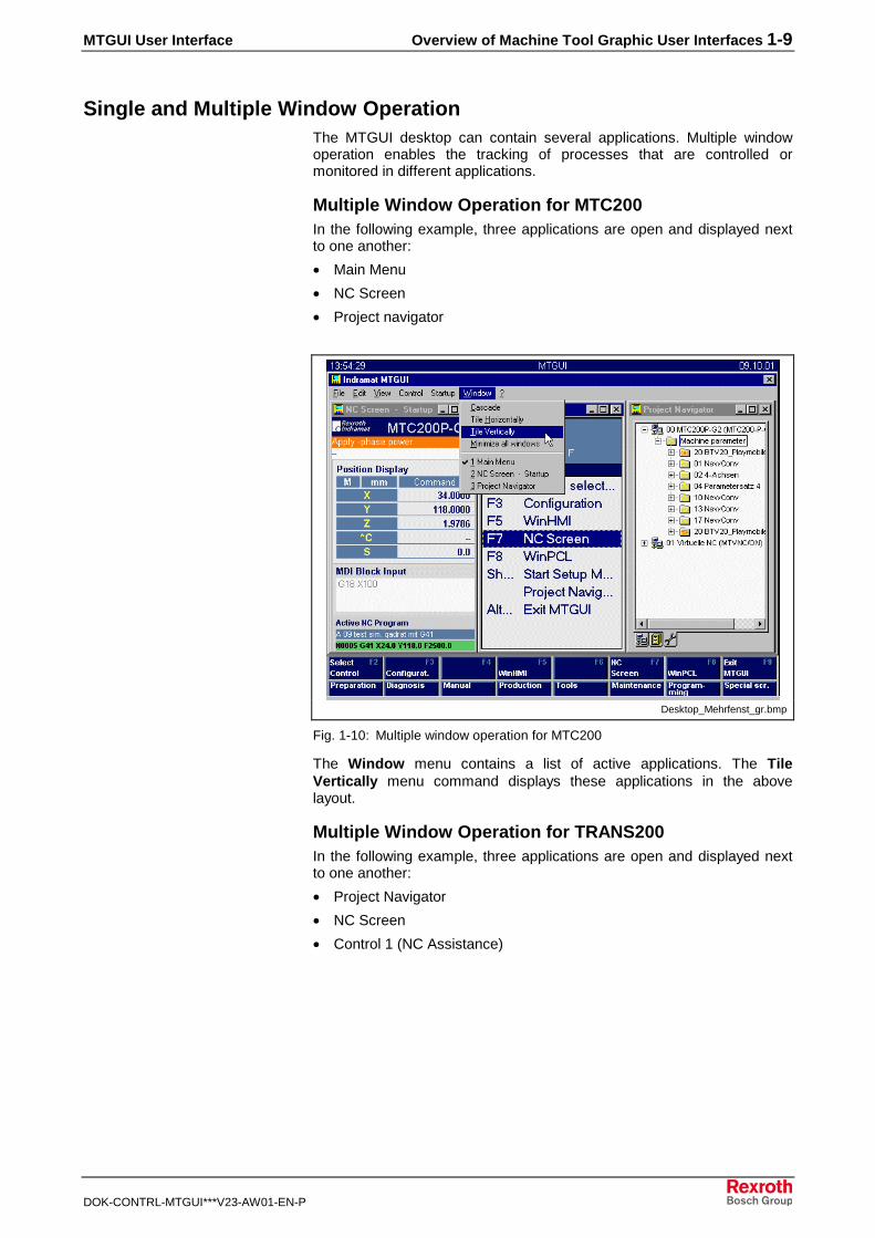
Single and Multiple Window OperationThe MTGUI desktop can contain several applications. Multiple windowoperation enables the tracking of processes that are controlled ormonitored in different applications.
Multiple Window Operation for MTC200In the following example, three applications are open and displayed nextto one another:
• Main Menu
• NC Screen
• Project navigator
Desktop_Mehrfenst_gr.bmp
Fig. 1-10: Multiple window operation for MTC200
The Window menu contains a list of active applications. The TileVertically menu command displays these applications in the abovelayout.
Multiple Window Operation for TRANS200In the following example, three applications are open and displayed nextto one another:
• Project Navigator
• NC Screen
• Control 1 (NC Assistance)

1-10 Overview of Machine Tool Graphic User Interfaces MTGUI User Interface
DOK-CONTRL-MTGUI***V23-AW01-EN-P
TransFenster_gr.bmp
Fig. 1-11: Multiple window operation for TRANS200
1.3 Starting the MT Interface
The MTGUI system must be installed on a PC with WinNT orWindows2000.
Start for MTC200MTC200 can be started via the icon in the Windows interface
or from the Windows Start menu:
Startmenu_gr.bmp
Fig. 1-12: Starting the MTGUI desktop for MTC200
When opened, the MTGUI desktop contains the "Main Menu (MTC200)"as the application.
The MTGUI desktop is the framework for various applications in theMTGUI system. The name of the application is displayed in the headerline of the desktop.

MTGUI User Interface Overview of Machine Tool Graphic User Interfaces 1-11
DOK-CONTRL-MTGUI***V23-AW01-EN-P
• Main menu
INDRAMAT MTGUI – [MAIN MENU]
• NC Screen
INDRAMAT MTGUI – [NC SCREEN - STARTUP]
• Setup menu
INDRAMAT MTGUI – [SETUP MENU]
• Project Navigator
INDRAMAT MTGUI – [PROJECT NAVIGATOR]
Start for TRANS200TRANS200 can be started via the icon in the Windows interface
or from the Windows Start menu:
Startmenu_Trans_gr.bmp
Fig. 1-13: Starting the MTGUI desktop for TRANS200
When opened, the MTGUI desktop contains the "Main Menu(TRANS200)" as the application.
1-12 Overview of Machine Tool Graphic User Interfaces MTGUI User Interface
DOK-CONTRL-MTGUI***V23-AW01-EN-P
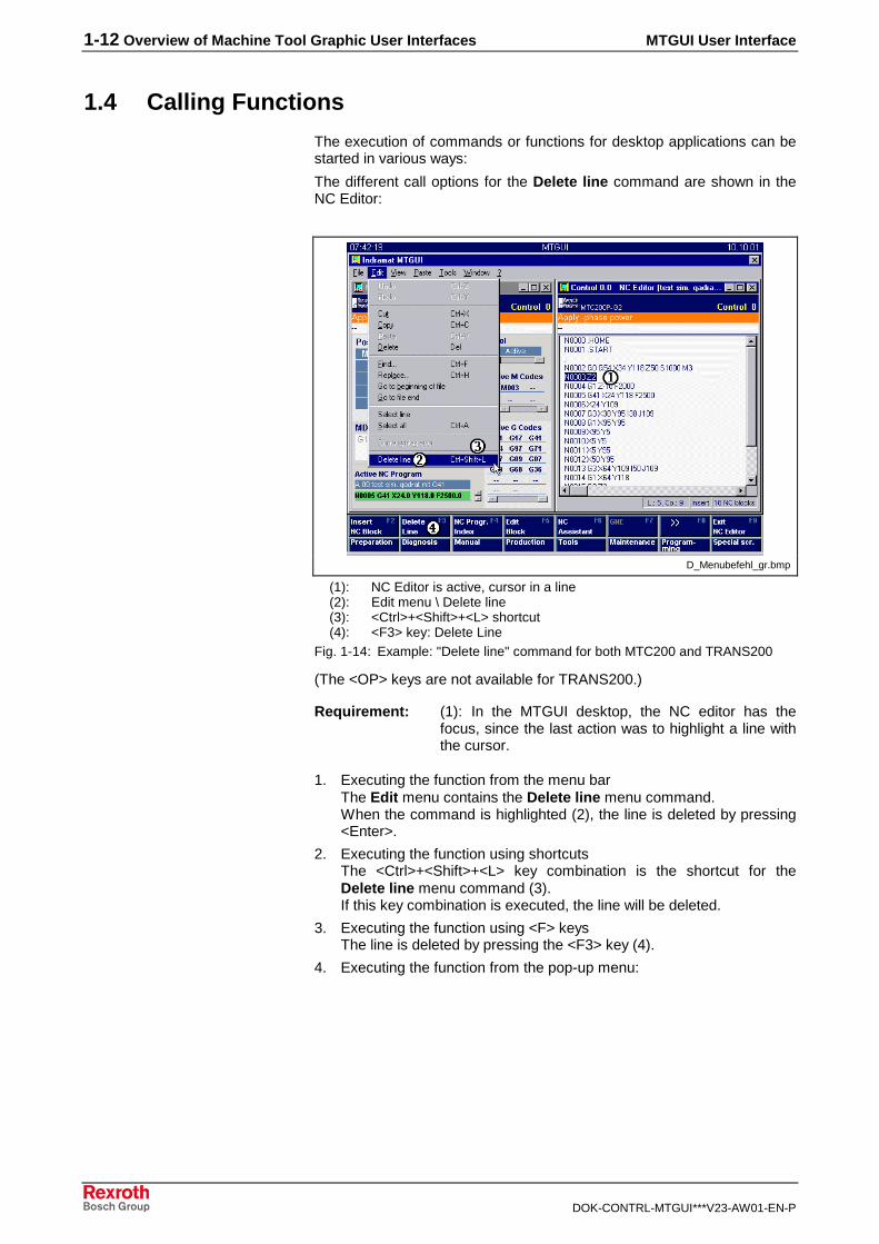
1.4 Calling Functions
The execution of commands or functions for desktop applications can bestarted in various ways:
The different call options for the Delete line command are shown in theNC Editor:
D_Menubefehl_gr.bmp
(1): NC Editor is active, cursor in a line(2): Edit menu \ Delete line(3): <Ctrl>+<Shift>+<L> shortcut(4): <F3> key: Delete Line
Fig. 1-14: Example: "Delete line" command for both MTC200 and TRANS200
(The <OP> keys are not available for TRANS200.)
Requirement: (1): In the MTGUI desktop, the NC editor has thefocus, since the last action was to highlight a line withthe cursor.
1. Executing the function from the menu barThe Edit menu contains the Delete line menu command. When the command is highlighted (2), the line is deleted by pressing<Enter>.
2. Executing the function using shortcutsThe <Ctrl>+<Shift>+<L> key combination is the shortcut for theDelete line menu command (3). If this key combination is executed, the line will be deleted.
3. Executing the function using <F> keys The line is deleted by pressing the <F3> key (4).
4. Executing the function from the pop-up menu:
MTGUI User Interface Overview of Machine Tool Graphic User Interfaces 1-13
DOK-CONTRL-MTGUI***V23-AW01-EN-P
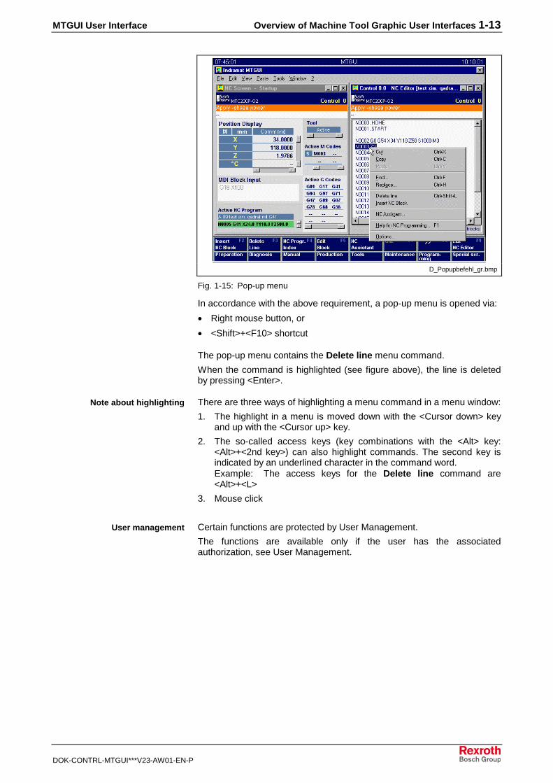
D_Popupbefehl_gr.bmp
Fig. 1-15: Pop-up menu
In accordance with the above requirement, a pop-up menu is opened via:
• Right mouse button, or
• <Shift>+<F10> shortcut
The pop-up menu contains the Delete line menu command.
When the command is highlighted (see figure above), the line is deletedby pressing <Enter>.
There are three ways of highlighting a menu command in a menu window:
1. The highlight in a menu is moved down with the <Cursor down> keyand up with the <Cursor up> key.
2. The so-called access keys (key combinations with the <Alt> key:<Alt>+<2nd key>) can also highlight commands. The second key isindicated by an underlined character in the command word. Example: The access keys for the Delete line command are<Alt>+<L>
3. Mouse click
Certain functions are protected by User Management.
The functions are available only if the user has the associatedauthorization, see User Management.
Note about highlighting
User management

1-14 Overview of Machine Tool Graphic User Interfaces MTGUI User Interface
DOK-CONTRL-MTGUI***V23-AW01-EN-P
1.5 Standard Operation of the MTGUI Desktop
The keyboards of the MTGUI interface are shown using a BTV20.3 as anexample:
Indramat
TEMP HD POWER
,
ESC OK
4 5 6 .SFT
1 2 3
0
DEL
ALTCTRL
INS
M9
M10
M11
M12
M13
M14
M15
M16
< F1 F10 > -7 8 9 N +
SP
TABINFONEXT
PROG
M1
M2
M3
M4
M5
M6
M7
M8
TEMP
OPERATOR PROG
HD POWER
OK
CTRL AL
SFT
DEL
ESC
<7
F18
F109
<N +
-
PROG4
-.65
,INS
3TA
2INFO
1NEXT
0SP
F2 F3
OP2
F4 F5 F6 F7 F8 F9
OP3 OP4 OP5 OP6 OP7 OP8 OP9
R1
R6
R8
R7
R5
R4
R3
R2
L1
L6
L8
L7
L5
L4
L3
L2
SYSTEM200 BTV20
F2 F3
OP2
F4 F5 F6 F7 F8 F9
OP3 OP4 OP5 OP6 OP7 OP8 OP9
1
3
2
4
5
5
5
OK
CTRL AL
SFT
DEL
ESC
F1 F10
PROG4
-.65
,INS
3TA
2INFO
1NEXT
0SP
<7 8 9 N +
-<
OP_Tast.FH7
(1): Overall view(2): Keypad(3): F key row(4): OP key row(5): Machine keys
Fig. 1-16: Operating keys on the BTV20.3
Keypad
BTV20 keypad => Standard keyboard Key functions of 1st level
1A1B1C1D1E2A2B2C2D2E3A3B3C3D3E4A
4B4C4D4E5A5B5C5D5E6AB6C6DE
<;><F1><F10><:><-><Ctrl>+<Shift>+<Alt>+<Q>no corresponding key<Alt><Ctrl>+<F6><Shift><Ctrl>+<Shift>+<Alt>+<N>no corresponding key<Tab><Ins><Del>no corresponding key
<Space><Cursor up><Ctrl><Alt><Page up><Cursor left>no corresponding key<Cursor right><Page down><Esc><Cursor down><Enter>
SemicolonAssigned to the active applicationAssigned to the active applicationColonMinus signOpens the main menunot assignedSets focus on the menu barSwitches windows<Shift> function of the standard keyboardSwitches controls in WinHMICalls the Information windowSwitches the focus in the active applicationSwitches between Insert <=> OverwriteDeleteSwitch (together with 2nd
key) to 2nd level
Example: Key <7> = key <1A> + key <4A>Moves highlight downwardsMoves highlight upwards<Ctrl> function of the standard keyboardSets focus in the menu barMoves highlight to topMoves highlight to leftMaximize windowMoves highlight to rightMoves highlight to bottomRemoves highlight in menu bar and windowMoves highlight downwardsActivates the highlighted command
Fig. 1-17: BTV20 keypad
MTGUI User Interface Overview of Machine Tool Graphic User Interfaces 1-15
DOK-CONTRL-MTGUI***V23-AW01-EN-P
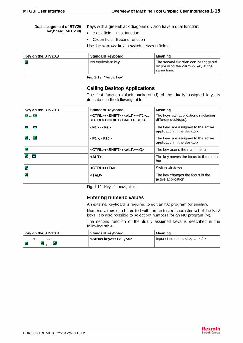
Keys with a green/black diagonal division have a dual function:
• Black field: First function
• Green field: Second function
Use the <arrow> key to switch between fields:
Key on the BTV20.3 Standard keyboard Meaning
No equivalent key The second function can be triggeredby pressing the <arrow> key at thesame time.
Fig. 1-18: "Arrow key"
Calling Desktop ApplicationsThe first function (black background) of the dually assigned keys isdescribed in the following table.
Key on the BTV20.3 Standard keyboard Meaning
... <CTRL>+<SHIFT>+<ALT>+<F2>...<CTRL>+<SHIFT>+<ALT>+<F9>
The keys call applications (includingdifferent desktops).
... <F2> - <F9> The keys are assigned to the activeapplication in the desktop.
, <F1>, <F10> The keys are assigned to the activeapplication in the desktop.
<CTRL>+<SHIFT>+<ALT>+<Q> The key opens the main menu.
, <ALT> The key moves the focus to the menubar.
<CTRL>+<F6> Switch windows.
<TAB> The key changes the focus in theactive application.
Fig. 1-19: Keys for navigation
Entering numeric valuesAn external keyboard is required to edit an NC program (or similar).
Numeric values can be edited with the restricted character set of the BTVkeys. It is also possible to select set numbers for an NC program (N).
The second function of the dually assigned keys is described in thefollowing table.
Key on the BTV20.3 Standard keyboard Meaning
+ ,
... ,
<Arrow key>+<1> - , <9> Input of numbers <1>, ... , <9>
Dual assignment of BTV20keyboard (MTC200)

1-16 Overview of Machine Tool Graphic User Interfaces MTGUI User Interface
DOK-CONTRL-MTGUI***V23-AW01-EN-P
1.6 System Error Display
The system error display shows current system errors and current localmechanism errors. The mechanism errors always relate to a device, e.g.M0 indicates one or more mechanism errors in control 0, and C1indicates a system error in control 1.
The header line of the MTGUI desktop contains the current system andmechanism errors for all connected devices.
Systemfehler_gr.bmp
(1): System errors and mechanism errors(2): Open the system error display with <Alt>+<F2>
Fig. 1-20: System error display
The errors are shown in an error display (1) in the MTGUI desktop (seefigure above):
• C error System error (red)
• M error Mechanism error (yellow)
The error number corresponds to the device address or control number.
The error dialog box can be opened by pressing the <Alt>+<F2> keys (2).This is possible only if an error exists. Here the user is provided withadditional information about the displayed error code:

MTGUI User Interface Overview of Machine Tool Graphic User Interfaces 1-17
DOK-CONTRL-MTGUI***V23-AW01-EN-P
Systemfehler1_gr.bmp
Fig. 1-21: System error display dialog box
The columns in the table contain the following information:
• Error type
• Device or device name
• Short description of the error
• Time the error occurred
Additional information (if available) is displayed when the error ishighlighted in the table:
Systemfehler2_gr.bmp
Fig. 1-22: Additional error description
<Alt>+<F2>
1-18 Overview of Machine Tool Graphic User Interfaces MTGUI User Interface
DOK-CONTRL-MTGUI***V23-AW01-EN-P
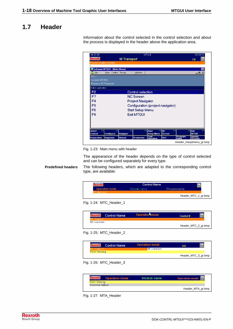
1.7 Header
Information about the control selected in the control selection and aboutthe process is displayed in the header above the application area.
Header_Hauptmenu_gr.bmp
Fig. 1-23: Main menu with header
The appearance of the header depends on the type of control selectedand can be configured separately for every type.
The following headers, which are adapted to the corresponding controltype, are available:
Header_MTC_1_gr.bmp
Fig. 1-24: MTC_Header_1
Header_MTC_2_gr.bmp
Fig. 1-25: MTC_Header_2
Header_MTC_3_gr.bmp
Fig. 1-26: MTC_Header_3
Header_MTA_gr.bmp
Fig. 1-27: MTA_Header
Predefined headers
MTGUI User Interface Overview of Machine Tool Graphic User Interfaces 1-19
DOK-CONTRL-MTGUI***V23-AW01-EN-P
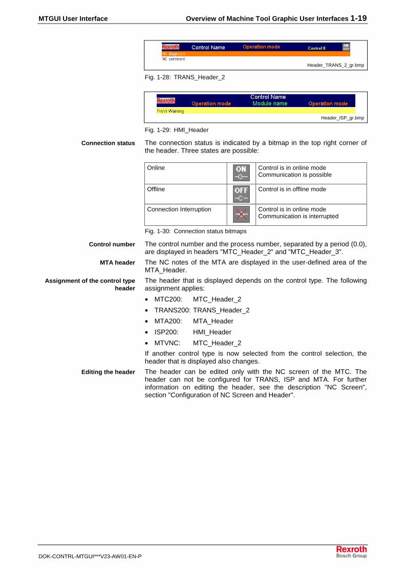
Header_TRANS_2_gr.bmp
Fig. 1-28: TRANS_Header_2
Header_ISP_gr.bmp
Fig. 1-29: HMI_Header
The connection status is indicated by a bitmap in the top right corner ofthe header. Three states are possible:
Online Control is in online modeCommunication is possible
Offline Control is in offline mode
Connection Interruption Control is in online modeCommunication is interrupted
Fig. 1-30: Connection status bitmaps
The control number and the process number, separated by a period (0.0),are displayed in headers "MTC_Header_2" and "MTC_Header_3".
The NC notes of the MTA are displayed in the user-defined area of theMTA_Header.
The header that is displayed depends on the control type. The followingassignment applies:
• MTC200: MTC_Header_2
• TRANS200: TRANS_Header_2
• MTA200: MTA_Header
• ISP200: HMI_Header
• MTVNC: MTC_Header_2
If another control type is now selected from the control selection, theheader that is displayed also changes.
The header can be edited only with the NC screen of the MTC. Theheader can not be configured for TRANS, ISP and MTA. For furtherinformation on editing the header, see the description "NC Screen",section "Configuration of NC Screen and Header".
Connection status
Control number
MTA header
Assignment of the control typeheader
Editing the header

1-20 Overview of Machine Tool Graphic User Interfaces MTGUI User Interface
DOK-CONTRL-MTGUI***V23-AW01-EN-P
1.8 Offline Operation
Offline operation is required mainly in the program development andcommissioning phases of the machine, less often in the production phaseof the machine.
Offline operation permits certain interface functions to be used withoutrequiring a control unit.
• Creating and editing user data such as NC programs, I/Oconfiguration, etc.
• Designing and configuring interface functions.
Note: For this, a parameter record must be active. The parameterrecord provides the axes, limit values, etc. that are required forthe machine.
When the control unit is switched to offline operation, the communicationto the control unit is switched off. States and data from the control are nolonger displayed. Only selected functions are still available.
The control unit selector is used to switch between online and offlineoperation.
In offline operation, there is an error message with No. 2011651159.
In offline operation, the data records that were last preselected or activeare indicated by dimmed CNC symbols.
• Dimmed CNC symbols in the tree and list of the Project Navigator, e.g.for the active parameter record.
• Dimmed CNC symbols in the editors for indicating the online files foroffsets, NC variables, NC events and D corrections.
1.9 Language Switching
See chapt. "Setup Menu: Language Selection" in "Setup Menu".
1.10 Connection Interruption
An interrupted connection is an erroneous state. This state occurs whenthe control is disconnected from the interface in online operation, e.g.when the serial connection to the PC is connected in the case of a RECOcontrol unit.
When a connection is interrupted, there is no communication between thecontrol and the interface. States and data from the control are no longerupdated or displayed. Only selected functions are still available.
System error No. xxx exists in the case of a connection interruption.
When a connection is interrupted, the data records that were lastpreselected or active are indicated by dimmed CNC symbols. Also seeOffline Operation.
Characteristics of offlineoperation
Switching
Identification of offline operation
Features
Indication of the connectioninterruption

MTGUI User Interface Overview of Machine Tool Graphic User Interfaces 1-21
DOK-CONTRL-MTGUI***V23-AW01-EN-P
There are two procedures for this:
• Direct elimination of the cause of the error:
• After the cause of the error has been eliminated, the interfaceautomatically reconnects to the control.
• Use of offline operation for elimination
• Switch the control to offline operation.
• Eliminate the cause of the error.
• Switch the control to online operation.
Elimination of the connectioninterruption

1-22 Overview of Machine Tool Graphic User Interfaces MTGUI User Interface
DOK-CONTRL-MTGUI***V23-AW01-EN-P
MTGUI User Interface Applications in the MT Interface 2-1
DOK-CONTRL-MTGUI***V23-AW01-EN-P
2 Applications in the MT Interface
2.1 MTGUI Desktop
The MTGUI desktop is the central desktop for MTC200 and TRANS200.The following applications run in the MTGUI desktop:
• Main Menu
• Control Selection (adapted)
• NC Screen
• Project Navigator
• Setup Menu
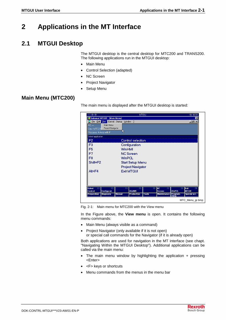
Main Menu (MTC200)The main menu is displayed after the MTGUI desktop is started:
MTC_Menu_gr.bmp
Fig. 2-1: Main menu for MTC200 with the View menu
In the Figure above, the View menu is open. It contains the followingmenu commands:
• Main Menu (always visible as a command)
• Project Navigator (only available if it is not open)or special call commands for the Navigator (if it is already open)
Both applications are used for navigation in the MT interface (see chapt."Navigating Within the MTGUI Desktop"). Additional applications can becalled via the main menu:
• The main menu window by highlighting the application + pressing<Enter>
• <F> keys or shortcuts
• Menu commands from the menus in the menu bar
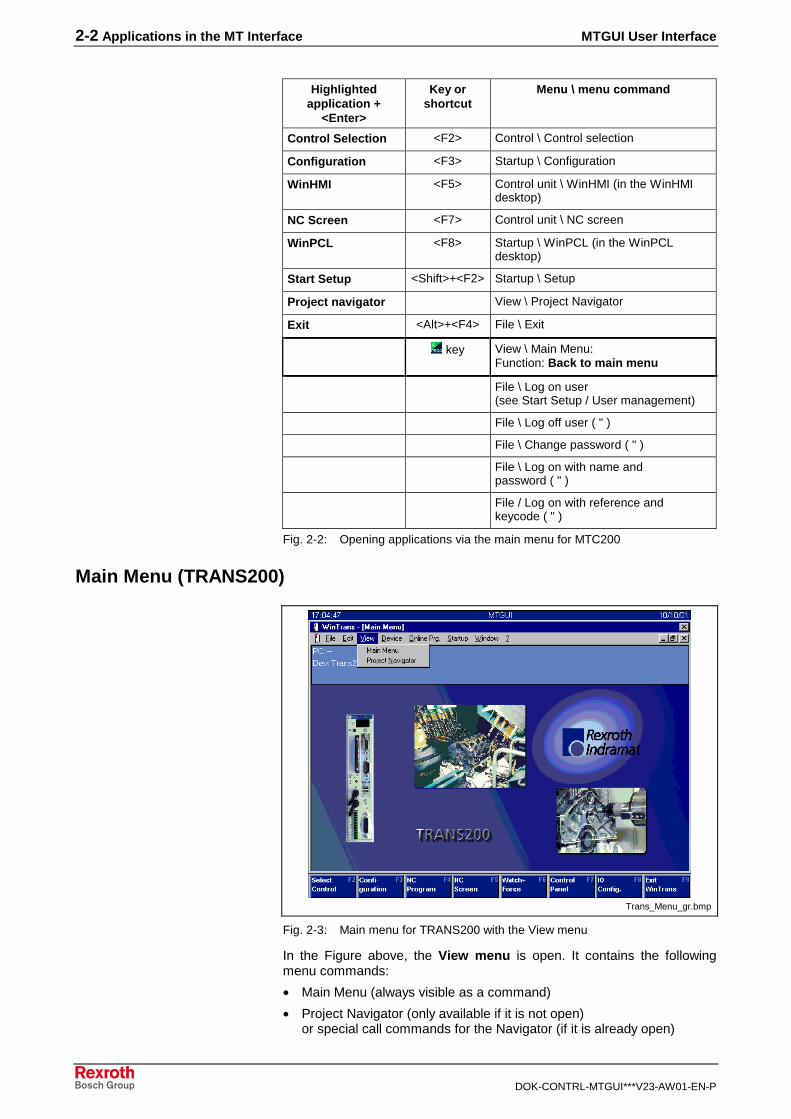
2-2 Applications in the MT Interface MTGUI User Interface
DOK-CONTRL-MTGUI***V23-AW01-EN-P
Highlightedapplication +
<Enter>
Key orshortcut
Menu \ menu command
Control Selection <F2> Control \ Control selection
Configuration <F3> Startup \ Configuration
WinHMI <F5> Control unit \ WinHMI (in the WinHMIdesktop)
NC Screen <F7> Control unit \ NC screen
WinPCL <F8> Startup \ WinPCL (in the WinPCLdesktop)
Start Setup <Shift>+<F2> Startup \ Setup
Project navigator View \ Project Navigator
Exit <Alt>+<F4> File \ Exit
key View \ Main Menu:Function: Back to main menu
File \ Log on user(see Start Setup / User management)
File \ Log off user ( " )
File \ Change password ( " )
File \ Log on with name andpassword ( " )
File / Log on with reference andkeycode ( " )
Fig. 2-2: Opening applications via the main menu for MTC200
Main Menu (TRANS200)
Trans_Menu_gr.bmp
Fig. 2-3: Main menu for TRANS200 with the View menu
In the Figure above, the View menu is open. It contains the followingmenu commands:
• Main Menu (always visible as a command)
• Project Navigator (only available if it is not open)or special call commands for the Navigator (if it is already open)

MTGUI User Interface Applications in the MT Interface 2-3
DOK-CONTRL-MTGUI***V23-AW01-EN-P
Both applications are used for navigation in the MT interface (see section"Navigating in the MT Interface"). Additional applications can be called viathe main menu:
• <F> keys or shortcuts
• Menu commands from the menus in the menu bar
Application Key orshortcut
Menu \ menu command
Control selection <F2> Device \ Control selection
Configuration <F3> Startup \ Configuration
NC Program <F4> Startup \ NC Programs
NC Screen <F5> Online prg. \ NC Screen
Watch+Force <F6> Online prg. \ Watch+Force
Control Functions <F7> Online prg. \ Control functions
I/O Configuration <F8> Startup \ I/O Config.
Exit WinTrans <F9><Alt>+<F4>
File \ Exit
Start Setup <Shift>+<F2> Startup \ Setup
Project navigator View \ Project Navigator
Main Menu View \ Main Menu
Fig. 2-4: Opening applications via the main menu for TRANS200
Control Selection (MTC200)Control selection is a special application which can be used by both theMTGUI desktop and (in a slightly different configuration) the HMI desktop.See also the WinHMI description.
Control selection is used to select a control from the available controls.The machine tool interface that appears on the screen is then alwaysbased on the selected control.
2-4 Applications in the MT Interface MTGUI User Interface
DOK-CONTRL-MTGUI***V23-AW01-EN-P
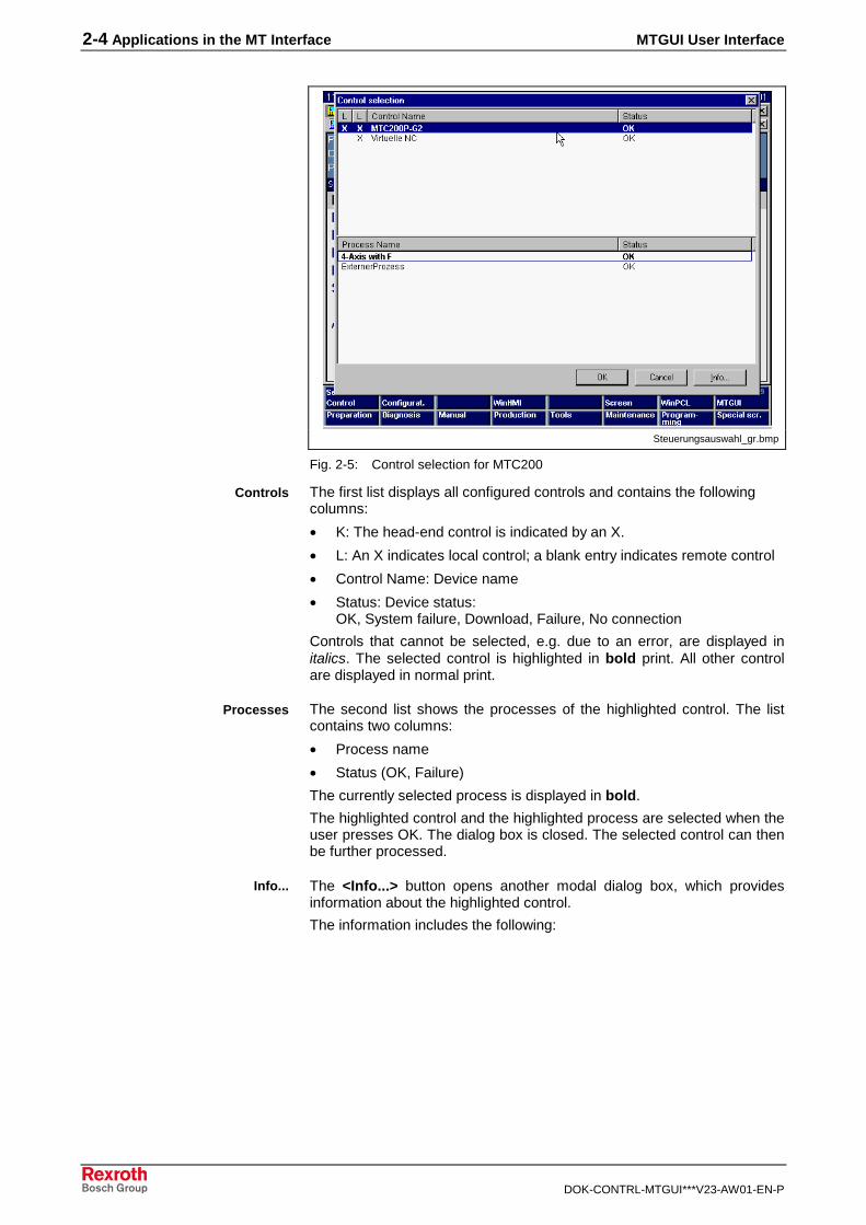
Steuerungsauswahl_gr.bmp
Fig. 2-5: Control selection for MTC200
The first list displays all configured controls and contains the followingcolumns:
• K: The head-end control is indicated by an X.
• L: An X indicates local control; a blank entry indicates remote control
• Control Name: Device name
• Status: Device status:OK, System failure, Download, Failure, No connection
Controls that cannot be selected, e.g. due to an error, are displayed initalics. The selected control is highlighted in bold print. All other controlare displayed in normal print.
The second list shows the processes of the highlighted control. The listcontains two columns:
• Process name
• Status (OK, Failure)
The currently selected process is displayed in bold.
The highlighted control and the highlighted process are selected when theuser presses OK. The dialog box is closed. The selected control can thenbe further processed.
The <Info...> button opens another modal dialog box, which providesinformation about the highlighted control.
The information includes the following:
Controls
Processes
Info...

MTGUI User Interface Applications in the MT Interface 2-5
DOK-CONTRL-MTGUI***V23-AW01-EN-P
a_steuerausw_info.bmp
Fig. 2-6: Information about the selected control
• Number of the PC to which the control is assigned
• Local device address
• Device type
• FarDevice address
Switching Online/Offline (MTC200)The ON <-> OFF button is used to switch between online and offlineoperation (see Fig. in "Control Selection (MTC200)").
Depending on the current state of the marked control, it can be switchedto offline or online operation. Information regarding the switch is providedin a message box; in addition, the switch can be cancelled here. Thestatus of the selected control is updated as soon as the control responds.
The control is switched to offline operation. States and data from thecontrol are no longer displayed. Only selected functions are still available.Communication to the control is switched off.
Control unit XYZ highlighted in the Control Selection window is switchedto online operation. Beforehand, ensure that communication with thecontrol is possible.
Switching the control between online and offline operation is password-protected in User Management. The right "Switch to online/offlineoperation" is located in the "General" tab in User Management.
Only local controls can be switched between online and offline operation.
Remote control that are in offline operation can not be selected in Controlselection.
Switching to offline operation
Switching to online operation
Switching protection

2-6 Applications in the MT Interface MTGUI User Interface
DOK-CONTRL-MTGUI***V23-AW01-EN-P
Control Selection (TRANS200)The Control selection menu item is called with the <F2> key. Itcorresponds to Control selection for the MTC200 but is more limited, inthat processes cannot be selected (only one process per control).
Steuerungsauswahl_T_gr.bmp
Fig. 2-7: Control selection for TRANS200
See "Control Selection (MTC200)".
Project NavigatorA detailed description of the Project Navigator can be found in the"General" section.
In the main menu, the <F3> key opens the Configuration tab in theProject Navigator application. The various control configurations can becarried out here.
ProjectNavigatorConfig_gr.bmp
Fig. 2-8: Project Navigator with the "Configuration" tab
MTGUI User Interface Applications in the MT Interface 2-7
DOK-CONTRL-MTGUI***V23-AW01-EN-P
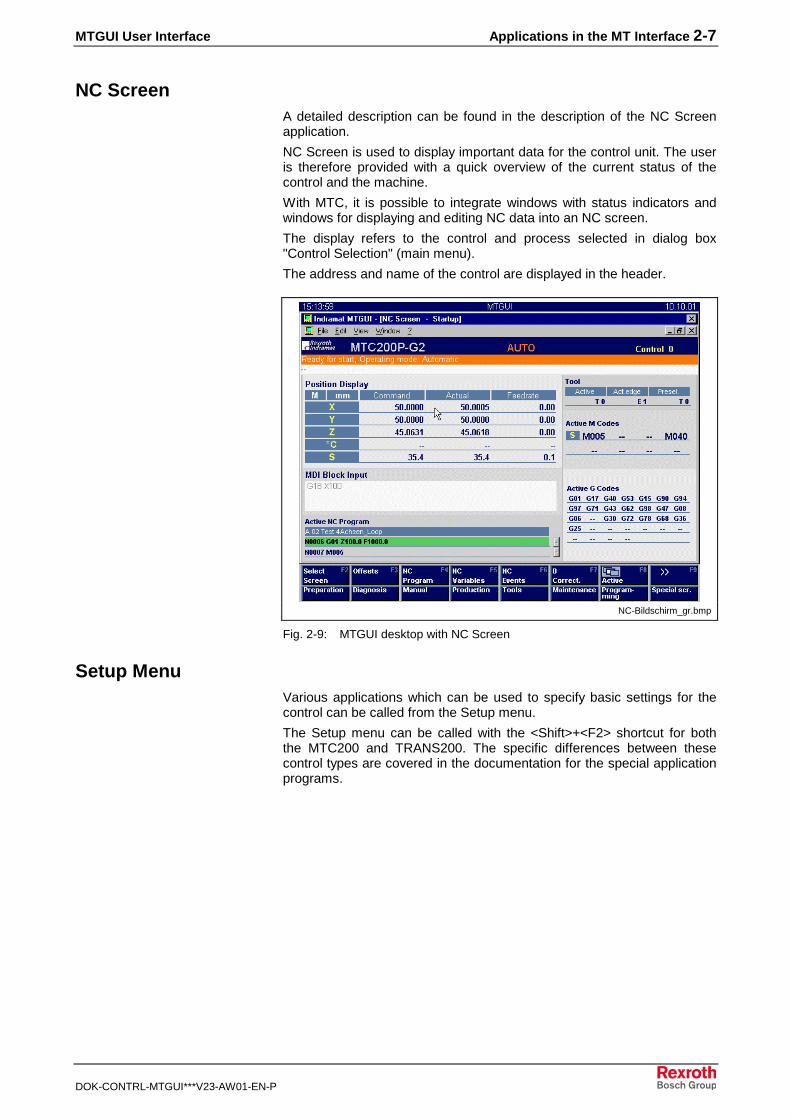
NC ScreenA detailed description can be found in the description of the NC Screenapplication.
NC Screen is used to display important data for the control unit. The useris therefore provided with a quick overview of the current status of thecontrol and the machine.
With MTC, it is possible to integrate windows with status indicators andwindows for displaying and editing NC data into an NC screen.
The display refers to the control and process selected in dialog box"Control Selection" (main menu).
The address and name of the control are displayed in the header.
NC-Bildschirm_gr.bmp
Fig. 2-9: MTGUI desktop with NC Screen
Setup MenuVarious applications which can be used to specify basic settings for thecontrol can be called from the Setup menu.
The Setup menu can be called with the <Shift>+<F2> shortcut for boththe MTC200 and TRANS200. The specific differences between thesecontrol types are covered in the documentation for the special applicationprograms.

2-8 Applications in the MT Interface MTGUI User Interface
DOK-CONTRL-MTGUI***V23-AW01-EN-P
SetupMenue_gr.bmp
Fig. 2-10: Setup menu
Setup Menu: Firmware ManagementA detailed description can be found in the documentation "Setup".
Bosch Rexroth control components are equipped with electrically erasableflash memories. Replacing EPROM chips is not necessary to install orupdate the firmware. Instead, the firmware is simply loaded on the PC.
Setup Menu: User ManagementA detailed description can be found in the documentation "Setup".
User Management ensures that only authorized personnel have access toprotected functions (and program parts). Before a protected function isexecuted, the user must register with User Management.
Setup Menu: Remote PG SetupA detailed description can be found in the documentation "Setup".
The PG interface is a performance feature which, in conjunction with theappropriate client software, enables remote programming of the PLC.With the aid of this add-on, the user can allow or prevent remoteprogramming of the PLC for this computer.
Setup Menu: Teleservice SetupA detailed description can be found in the documentation "Setup".
The TS interface is a performance feature which, in conjunction with theappropriate client software, enables remote operation of the computer.With the aid of this add-on, the user can allow or prevent remoteoperation of this computer.
Setup Menu: Message IntegratorA detailed description can be found in the documentation "Setup".
Diagnostic message handling includes:
• processing of process messages and system faults
• processing of general PLC and sequencer errors.
General PLC and sequencer errors are processed using the externalMessage Integrator application, which is available in Version 18 or later.

MTGUI User Interface Applications in the MT Interface 2-9
DOK-CONTRL-MTGUI***V23-AW01-EN-P
Dialog boxes for processing process messages and system faults arealready integrated in the MTGUI.
The Message Integrator dialog boxes that are currently integrated in theMTGUI enable the user to:
• modify process messages and system faults specified by BoschRexroth with the relevant additional information
• add user-created process messages and system faults.
See Message Integrator (Messagesint_de.hlp).
Setup Menu: BackupThis menu is used to save control unit data.
A detailed description can be found in the documentation "SystemServices".
Setup Menu: RestoreThis menu is used to restore control data.
A detailed description can be found in the documentation "SystemServices".
Setup Menu: Email ConfigurationThe email connection allows event-driven sending of messages, such asmaintenance instructions or fault messages, via email, SMS or fax tovarious devices such as a PC, cell phone or pager.
A detailed description can be found in the documentation "SystemServices".
Setup Menu: License ManagementThe License Management System (LMS) manages licensing of thestandard range of functions of the MTGUI as well as the enablement ofcertain additional components (= options).
A detailed description can be found in the documentation "SystemServices".
Setup Menu: Language Selection
Sprachumschaltung_gr.bmp
Fig. 2-11: Switching languages

2-10 Applications in the MT Interface MTGUI User Interface
DOK-CONTRL-MTGUI***V23-AW01-EN-P
Key <F2> is used to switch the set language.
In the example (see Fig. above), a switch from the current language(English) to the German language setting can be made.
1. Press <F2>.The label of <F2> changes.
2. Exit the setting dialog box with <F9>.3. Exit the MTGUI desktop.
Note: The new language goes into effect when the MTGUI interfaceis restarted.
2.2 WinHMI Desktop (MTC200 Only)
The WinHMI desktop is not available for the TRANS200.
A detailed description can be found in the WinHMI description.
HMI_gr.bmp
Fig. 2-12: WinHMI desktop with machine overview
The applications in the WinHMI desktop are described in DOK-MTC200-WIN-HMI*V19-AW01-EN-P (288996).

MTGUI User Interface Applications in the MT Interface 2-11
DOK-CONTRL-MTGUI***V23-AW01-EN-P
2.3 WinPCL Desktop (MTC200 Only)
The WinPCL desktop is not available for the TRANS200.
PCL_gr.bmp
Fig. 2-13: WinPCL desktop with action window
The applications in the WINPCL desktop are described in DOC-CONTRL-WINPCL*3VRS-AW01-EN-P (291135).
2.4 DriveTop Desktop
The Drivetop desktop is used by the MTC200 and TRANS200.
DriveTop_gr.bmp
Fig. 2-14: DriveTop desktop with mechanical gear dialog box
The functions of DriveTop are used to configure drive parameters and tocommission the drives.

2-12 Applications in the MT Interface MTGUI User Interface
DOK-CONTRL-MTGUI***V23-AW01-EN-P

MTGUI User Interface Navigating in the MT Interface 3-1
DOK-CONTRL-MTGUI***V23-AW01-EN-P
3 Navigating in the MT Interface
3.1 Desktop Selection from the Main Menu (MTC200)
The desktop is changed by switching tasks in the Windows system.
Taskwechsel1_gr.bmp
Fig. 3-1: Navigating between desktops
The figure (above) shows how to access the applications in the variousdesktops from the main menu (MTGUI desktop) for MTC200.
The NC-specific functions (e.g. NC Screen) and the Project Navigator areapplications in the MTGUI desktop.
Use <F5> to access HMI.
Use <F8> to call PCL.

3-2 Navigating in the MT Interface MTGUI User Interface
DOK-CONTRL-MTGUI***V23-AW01-EN-P
To access DriveTop, call the configuration in the Project Navigator with<F2>. DriveTop is opened by selecting the SERCOS drive parametersand pressing <Enter>.
To return to the applications in the MTGUI desktop, press the <PROG>key on the BTV20 (not DriveTop) or switch tasks using the <Alt>+<Tab>key combination.
3.2 Changing Desktops Using Project Navigator
Project Navigator can also be used to change between the MTGUIdesktop (referred to here as NC) and the PCL desktop (referred to asPLC).
First, Project Navigator must be opened via the main menu either byhighlighting "Project Navigator" and pressing <Enter> or via theView/Project Navigator menu command.
ProNavNCSPS.bmp
MTGUI desktop WinPCL desktopFig. 3-2: Switching tasks using Project Navigator
The PLC can be called from Project Navigator (MTGUI desktop contents).
The NC can be called from Project Navigator (WinPCL desktop contents).

MTGUI User Interface Navigating in the MT Interface 3-3
DOK-CONTRL-MTGUI***V23-AW01-EN-P
3.3 Navigating Within the MTGUI Desktop
Open desktop applications can be activated via the Window menu.
ProNavFenster_gr.bmp
Fig. 3-3: Open applications in the MTGUI desktop
In the figure above, the applications in the MTGUI desktop are displayednext to one another (Tile Vertically menu command). The followingapplications are open:
• Project navigator
• NC Screen - Startup
• NC Editor (control unit 0.0 with NC Program Test1)
Press button to maximize the window size of the correspondingapplication.
The applications can be selected via the Window menu.

3-4 Navigating in the MT Interface MTGUI User Interface
DOK-CONTRL-MTGUI***V23-AW01-EN-P
ProNavFensterMax_gr.bmp
Fig. 3-4: Window menu in the MTGUI desktop
The <F> keys are assigned by the active application.
1. figure: Active application: NC Editor Editor keys
2. figure: Active application: NC Screen NC Screen keys
Note on the <F> key bar

MTGUI User Interface Project Navigator 4-1
DOK-CONTRL-MTGUI***V23-AW01-EN-P
4 Project Navigator
4.1 General Information About Project Navigator
Project Navigator is a tool used for navigation in the diverse data of all theconfigured controls of a PC. For this purpose it offers:
• different instances (window layout) and views (structure of the data)
• command input via the main menu, contextual menu and functionkeys
• specific access to online and offline data
• specific programmer and user actions for each data type
• standard functions such as New, Edit (calling an editor), Download(loading to the control), etc.
InstancesIn the "Tree+List" instance, a tree structure is displayed on the left-handside of the window and a list on the right-hand side, which displaysadditional information about the highlighted entry, if available. The figurebelow is an example of this instance:
ProjectNavigatorMenu_gr.bmp
Fig. 4-1: Project Navigator in the "Tree+List" instance
In the "List" instance, only a list is displayed. This display is used, forexample, when only one selection is to be made within a data typespecified by a different application. The figure below is an example of thisinstance:
Tree+List
List
4-2 Project Navigator MTGUI User Interface
DOK-CONTRL-MTGUI***V23-AW01-EN-P
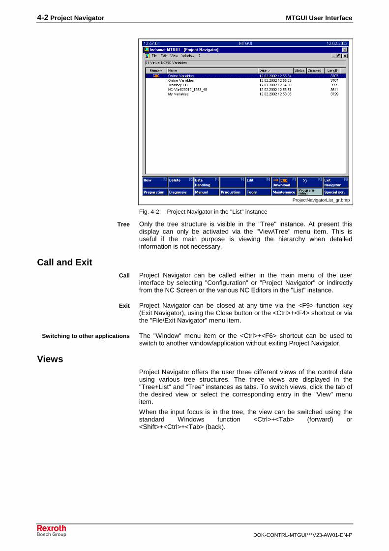
ProjectNavigatorList_gr.bmp
Fig. 4-2: Project Navigator in the "List" instance
Only the tree structure is visible in the "Tree" instance. At present thisdisplay can only be activated via the "View\Tree" menu item. This isuseful if the main purpose is viewing the hierarchy when detailedinformation is not necessary.
Call and ExitProject Navigator can be called either in the main menu of the userinterface by selecting "Configuration" or "Project Navigator" or indirectlyfrom the NC Screen or the various NC Editors in the "List" instance.
Project Navigator can be closed at any time via the <F9> function key(Exit Navigator), using the Close button or the <Ctrl>+<F4> shortcut or viathe "File\Exit Navigator" menu item.
The "Window" menu item or the <Ctrl>+<F6> shortcut can be used toswitch to another window/application without exiting Project Navigator.
ViewsProject Navigator offers the user three different views of the control datausing various tree structures. The three views are displayed in the"Tree+List" and "Tree" instances as tabs. To switch views, click the tab ofthe desired view or select the corresponding entry in the "View" menuitem.
When the input focus is in the tree, the view can be switched using thestandard Windows function <Ctrl>+<Tab> (forward) or<Shift>+<Ctrl>+<Tab> (back).
Tree
Call
Exit
Switching to other applications

MTGUI User Interface Project Navigator 4-3
DOK-CONTRL-MTGUI***V23-AW01-EN-P
View: Structure The figure below shows Project Navigator in Structure view:
ProjectNavigatorStructure_gr.bmp
Fig. 4-3: Project Navigator in Structure view
Structure view displays all the configured control units in the first level ofthe tree. The node designation (entries in trees are also called "nodes")consists of the address and the name. In the case of control units with thestatus "Offline", "(offline)" is also displayed and the node designation isdimmed. Controls that do not currently have a connection are alsodimmed.
Note: The order in which the controls are displayed in ProjectNavigator is the same as in the system configurator and canonly be modified there.
The appearance of an extended tree structure below the relevant controlnode depends on the control type and the configuration defined in theactive parameter set.
In addition, the tree structure for the MTC200 control family depends onthe module configuration specified in the "ModulDef.ini" file. This filespecifies whether modules exist and which configured processes areassigned to them. The corresponding module nodes are displayed withsubprocess nodes accordingly.
Specific entries which represent the relevant control unit data for theprocess or device are displayed for each control type. If a plus or minussymbol appears on the left of the entry, this means that the data is furtherstructured; otherwise the entry is an end node. In this case, additionalinformation is usually displayed in the list, as shown in the figure below.Certain end nodes (e.g. the "PLC", "NC Screen" or "Parameter" entries)offer only one command, which is triggered with the Enter key or bydouble-clicking the mouse, and enables the user to switch to the desiredapplication.
The "Cycle library" entry also appears below the control nodes when atleast one control from the MTC200 control familiy is configured (only this

4-4 Project Navigator MTGUI User Interface
DOK-CONTRL-MTGUI***V23-AW01-EN-P
control type has cycles and thus a cycle library). This is a special entry asit is not directly related to a control.
View: DataThe figure below is an example of Project Navigator in the "Tree+List"instance in Data view:
ProjectNavigatorData_gr.bmp
Fig. 4-4: Project Navigator in Data view
In contrast to Structure view, which offers control-oriented display of thedata, the different data types are in the foreground in Data view.
All data types that support the current configured control are displayed inData view. The relevant control offered by a data type are listed within theparticular data type. With regard to process-related data, the currentconfigured processes for an MTC200 control are also displayed.
For some nodes (e.g. "Tool Management" or "Cycle library") that are notdirectly related to a control, no control nodes are displayed.
As in Structure view, the "PLC" end node, which only appears if at leastone control is configured with a PLC, can be used to switch to WinPCLvia the Enter key or by double-clicking the mouse.
Since the control data are displayed according to data type, the user isprovided with an overview and faster access to these data.

MTGUI User Interface Project Navigator 4-5
DOK-CONTRL-MTGUI***V23-AW01-EN-P
View: ConfigurationThe figure below is an example of Project Navigator in Configuration view:
ProjectNavigatorConfig_gr.bmp
Fig. 4-5: Project Navigator in Configuration view
Configuration view has a similar layout to Structure view; however, onlycontrols that have machine parameters (MTC200, TRANS200, MTA200,MTVNC control types) and machine data (MTC200, MTVNC controltypes) are displayed in Configuration view. Only the "MachineParameters" entry with its special structure, which is explained in moredetail in the chapter about machine parameters and machine data,appears under the relevant control node.
Configuration view plays an important role in the configuration of controlunits, as it is only in this view that parameter sets can be created,modified and loaded in the appropriate control. The active parameter setof a control also influences the display in the other two views, as itdetermines which processes are defined and what they are called.
4-6 Project Navigator MTGUI User Interface
DOK-CONTRL-MTGUI***V23-AW01-EN-P
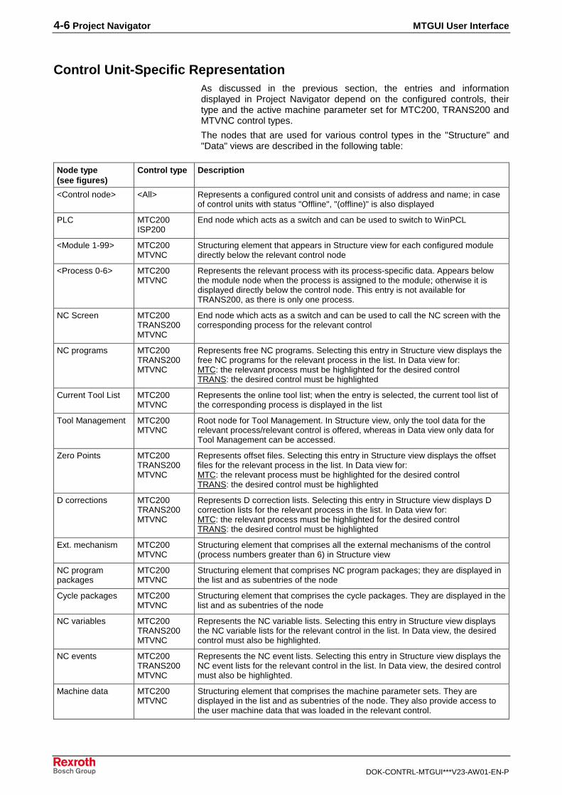
Control Unit-Specific RepresentationAs discussed in the previous section, the entries and informationdisplayed in Project Navigator depend on the configured controls, theirtype and the active machine parameter set for MTC200, TRANS200 andMTVNC control types.
The nodes that are used for various control types in the "Structure" and"Data" views are described in the following table:
Node type(see figures)
Control type Description
<Control node> <All> Represents a configured control unit and consists of address and name; in caseof control units with status "Offline", "(offline)" is also displayed
PLC MTC200ISP200
End node which acts as a switch and can be used to switch to WinPCL
<Module 1-99> MTC200MTVNC
Structuring element that appears in Structure view for each configured moduledirectly below the relevant control node
<Process 0-6> MTC200MTVNC
Represents the relevant process with its process-specific data. Appears belowthe module node when the process is assigned to the module; otherwise it isdisplayed directly below the control node. This entry is not available forTRANS200, as there is only one process.
NC Screen MTC200TRANS200MTVNC
End node which acts as a switch and can be used to call the NC screen with thecorresponding process for the relevant control
NC programs MTC200TRANS200MTVNC
Represents free NC programs. Selecting this entry in Structure view displays thefree NC programs for the relevant process in the list. In Data view for:MTC: the relevant process must be highlighted for the desired controlTRANS: the desired control must be highlighted
Current Tool List MTC200MTVNC
Represents the online tool list; when the entry is selected, the current tool list ofthe corresponding process is displayed in the list
Tool Management MTC200MTVNC
Root node for Tool Management. In Structure view, only the tool data for therelevant process/relevant control is offered, whereas in Data view only data forTool Management can be accessed.
Zero Points MTC200TRANS200MTVNC
Represents offset files. Selecting this entry in Structure view displays the offsetfiles for the relevant process in the list. In Data view for:MTC: the relevant process must be highlighted for the desired controlTRANS: the desired control must be highlighted
D corrections MTC200TRANS200MTVNC
Represents D correction lists. Selecting this entry in Structure view displays Dcorrection lists for the relevant process in the list. In Data view for:MTC: the relevant process must be highlighted for the desired controlTRANS: the desired control must be highlighted
Ext. mechanism MTC200MTVNC
Structuring element that comprises all the external mechanisms of the control(process numbers greater than 6) in Structure view
NC programpackages
MTC200MTVNC
Structuring element that comprises NC program packages; they are displayed inthe list and as subentries of the node
Cycle packages MTC200MTVNC
Structuring element that comprises the cycle packages. They are displayed in thelist and as subentries of the node
NC variables MTC200TRANS200MTVNC
Represents the NC variable lists. Selecting this entry in Structure view displaysthe NC variable lists for the relevant control in the list. In Data view, the desiredcontrol must also be highlighted.
NC events MTC200TRANS200MTVNC
Represents the NC event lists. Selecting this entry in Structure view displays theNC event lists for the relevant control in the list. In Data view, the desired controlmust also be highlighted.
Machine data MTC200MTVNC
Structuring element that comprises the machine parameter sets. They aredisplayed in the list and as subentries of the node. They also provide access tothe user machine data that was loaded in the relevant control.
MTGUI User Interface Project Navigator 4-7
DOK-CONTRL-MTGUI***V23-AW01-EN-P
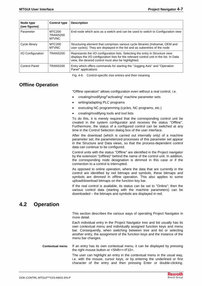
Node type(see figures)
Control type Description
Parameter MTC200TRANS200MTVNC
End node which acts as a switch and can be used to switch to Configuration view
Cycle library MTC200MTVNC
Structuring element that comprises various cycle libraries (Indramat, OEM anduser cycles). They are displayed in the list and as subentries of the node
I/O Configuration TRANS200 Represents the I/O configuration lists. Selecting the entry in Structure viewdisplays the I/O configuration lists for the relevant control unit in the list. In Dataview, the desired control must also be highlighted.
Control Panel TRANS200 Entry which offers commands for starting the "Jogging Axis" and "OperationPanel" applications
Fig. 4-6: Control-specific tree entries and their meaning
Offline Operation"Offline operation" allows configuration even without a real control, i.e.
• creating/modifying/"activating" machine parameter sets
• writing/adapting PLC programs
• executing NC programming (cycles, NC programs, etc.)
• creating/modifying tools and tool lists
To do this, it is merely required that the corresponding control unit becreated in the system configurator and receives the status "Offline".Furthermore, the status of a configured control can be switched at anytime in the Control Selection dialog box of the user interface.
After the download (which is carried out internally only) of a machineparameter set, the parameterized processes of this parameter set appearin the Structure and Data views, so that the process-dependent controldata can continue to be configured.
Control units with the status "Offline" are identified in the Project navigatorby the extension "(offline)" behind the name of the control unit. In addition,the corresponding node designation is dimmed in this case or if theconnection to a control is interrupted.
As opposed to online operation, where the data that are currently in thecontrol are identified by red bitmaps and symbols, these bitmaps andsymbols are dimmed in offline operation. This also applies to someupload/download bitmaps on the function key bar.
If the real control is available, its status can be set to "Online"; then thevarious control data (starting with the machine parameters) can bedownloaded – the bitmaps and symbols are displayed in red.
4.2 Operation
This section describes the various ways of operating Project Navigator inmore detail.
Each individual entry in the Project Navigator tree and list usually has itsown contextual menu and individually assigned function keys and menubar. Consequently, when switching between tree and list or selectinganother entry, the assignment of the function keys and the instance of themenu bar changes.
If an entry has its own contextual menu, it can be displayed by pressingthe right mouse button or <Shift>+<F10>.
The user can highlight an entry in the contextual menu in the usual way,i.e. with the mouse, cursor keys, or by entering the underlined or firstcharacter of the entry and then pressing Enter or double-clicking.
Contextual menu
4-8 Project Navigator MTGUI User Interface
DOK-CONTRL-MTGUI***V23-AW01-EN-P
Pressing the <Esc> key or clicking outside the contextual menu with themouse closes the menu without executing an action.
As previously discussed, the menu bar contains individual items for theentry that is focussed in Project Navigator. The entries can then beselected and activated in the same way as in the context menu by usingthe mouse or by pressing <F10> or <Alt>+<character> (<Alt>+underlinedcharacter in the menu bar).
The function key bar can be found at the bottom of the user interface andis displayed in the form of softkeys, which represent function keys <F2> to<F9>. The softkeys can be triggered by clicking with the left mouse buttonor by pressing the corresponding function key. As previously discussed,the individual softkeys are assigned according to the entry that isfocussed in Project Navigator.
Switching Between Tree and ListThe user can switch the input focus between tree and list by pressing the<Tab> key or by selecting the desired entry with the mouse. This isimportant, as any input via the keyboard is always applied to the entry thathas the focus. If the user wishes to navigate in the list and the focus is inthe tree, the focus can be moved to the list by simply pressing the <Tab>key. Pressing the <Tab> key again moves the focus back to thehighlighted tree entry.
Navigation in the TreeBoth the keyboard and mouse can be used to navigate in the tree. Themouse can be used to directly click individual entries to highlight them. Toopen or close an entry, click the plus or minus symbol on the left of theentry or double-click the entry itself.
Note: If the contextual menu for a node has a default entry, double-clicking with the mouse executes the entry instead of openingor closing the node. The default entry is indicated in thecontextual menu by a star before the entry.
When navigating with the keyboard, the <Cursor right> key is used toopen the current highlighted entry and the <Cursor left> key is used toclose it.
In addition, entries can be directly accessed by entering the first characterof the node name. In case of ambiguity, the next corresponding entry isselected.
The <Page up>, <Page down>, <Home> and <End> keys can be used inthe usual way to move one page up or down or to jump to the first or lastentry in the tree.
The cursor keys, as well as the <Page up> and <Page down> keys, areused together with <Ctrl> to move the visible section of the tree withoutchanging the selection.
Pressing the <Backspace> key moves the highlight to a higher-level entry,if one exists.
Menu bar
Function key bar

MTGUI User Interface Project Navigator 4-9
DOK-CONTRL-MTGUI***V23-AW01-EN-P
Navigation in the ListEntries are highlighted in the list by pressing the <Cursor up> and<Cursor down> keys or by clicking once with the mouse, whereas usingthe <Cursor left> and <Cursor right> keys moves the section of the list leftor right. Press the Enter key or double-click the mouse to trigger thedefault command for the current highlighted entry. If this command doesnot exist, the list changes to display the subentries of the highlightedentry, if they exist. As in the tree display, pressing the <Backspace> keymoves the focus up one level if a list display is available.
If multiple selection is permitted for the displayed List entries, all theentries can be highlighted by pressing <Ctrl>+<A>. Furthermore, it is thenpossible to select/deselect groups of entries or several individual entriesusing the <Shift> and <Ctrl> keys in the normal manner.
The <Page up>, <Page down>, <Home> and <End> keys can be used inthe usual way to move the screen up or down or to jump to the first or lastentry in the list.
For instances "Tree+List" and "List", there are two different degrees ofdetail in the List representation; these are selected automatically.However, if the list is wider than 400 pixels, the highest degree of detail isalways used.
The columns displayed in each degree of detail are preset for each datatype; however individual columns can be "hidden" by moving the columnsclosely together with the mouse. When this list type is displayed again,the column is displayed at the minimum width so that the user is awarethat the column is hidden. However, columns that are invisible by defaultfor a degree of detail can be "pulled out" by moving the mouse from theright over the corresponding column separator and pulling the column tothe right while pressing and holding the left mouse button.
The column and the direction of the sort can only be changed with themouse by clicking the appropriate column header one or more times. Asmall triangle then marks the current sorting column and indicates theselected sort direction; the point of the triangle shows the direction ofincreasing values.
Project Navigator saves the column width, the sorting column and thedirection of the sort for each degree of detail and each list type. Thesedata are saved to the hard disk when the view is changed or when ProjectNavigator is closed and exited.
When key combination <Shift>+<Home> is pressed when the entry focusis located in the list, the specified default values for the columnconfiguration can be reset for the currently active list type and thecurrently visible degree of detail.
Note: Information about column widths and sorting can be found inthe "PRONAV.INI" file in the"..\project_000\customdata\resource" directory. If the defaultvalues need to be reset or in the event of general problemswith the list display, this file can be safely deleted once theuser interface has been exited.

4-10 Project Navigator MTGUI User Interface
DOK-CONTRL-MTGUI***V23-AW01-EN-P

MTGUI User Interface Index 5-1
DOK-CONTRL-MTGUI***V23-AW01-EN-P
5 Index
AAdd-on 2-8Application Window 1-5
CCharacter set 1-15Configuration view 4-5Connection Interruption 1-20Connection status 1-19Contextual menu 4-7
DDriveTop 1-6, 2-11
EEmail connection 2-9
FFunction key bar 4-8Function selection list 1-7
HHeader 1-18Header line 1-5
LLicense Management System 2-9Listed screen resolutions 1-6
MMain menu bar 1-5Mechanism errors 1-16Menu bar 4-8Menu commands 1-5Message Integrator 2-8MTGUI interface 1-1
NNC Editor 1-12NC Screen 2-7
OOffline operation 1-20, 4-7Online operation 4-7Operation 1-4
PPG interface 2-8Process 2-4Project navigator 2-1, 2-6

5-2 Index MTGUI User Interface
DOK-CONTRL-MTGUI***V23-AW01-EN-P
RRemote operation 2-8Remote programming 2-8Restore 2-9
SSave 2-9Screen Layout 1-5Setup Menu 2-7Structure view 4-3
TTree structure 4-1
UUser Management 1-13User manager 2-8
WWinPCL desktop 2-11WinTRANS 1-6

MTGUI User Interface Service & Support 6-1
DOK-CONTRL-MTGUI***V23-AW01-EN-P
6 Service & Support
6.1 Helpdesk
Unser Kundendienst-Helpdesk im Hauptwerk Lohram Main steht Ihnen mit Rat und Tat zur Seite.Sie erreichen uns
Our service helpdesk at our headquarters in Lohr amMain, Germany can assist you in all kinds of inquiries.Contact us
- telefonisch - by phone: 49 (0) 9352 40 50 60über Service Call Entry Center Mo-Fr 07:00-18:00- via Service Call Entry Center Mo-Fr 7:00 am - 6:00 pm
- per Fax - by fax: +49 (0) 9352 40 49 41
- per e-Mail - by e-mail: [email protected]
6.2 Service-Hotline
Außerhalb der Helpdesk-Zeiten ist der Servicedirekt ansprechbar unter
After helpdesk hours, contact our servicedepartment directly at
+49 (0) 171 333 88 26
oder - or +49 (0) 172 660 04 06
6.3 Internet
Unter www.boschrexroth.com finden Sieergänzende Hinweise zu Service, Reparatur undTraining sowie die aktuellen Adressen *) unsererauf den folgenden Seiten aufgeführten Vertriebs-und Servicebüros.
Verkaufsniederlassungen
Niederlassungen mit Kundendienst
Außerhalb Deutschlands nehmen Sie bitte zuerst Kontakt mitunserem für Sie nächstgelegenen Ansprechpartner auf.
*) Die Angaben in der vorliegenden Dokumentation könnenseit Drucklegung überholt sein.
At www.boschrexroth.com you may findadditional notes about service, repairs and trainingin the Internet, as well as the actual addresses *)of our sales- and service facilities figuring on thefollowing pages.
sales agencies
offices providing service
Please contact our sales / service office in your area first.
*) Data in the present documentation may have becomeobsolete since printing.
6.4 Vor der Kontaktaufnahme... - Before contacting us...
Wir können Ihnen schnell und effizient helfen wennSie folgende Informationen bereithalten:
1. detaillierte Beschreibung der Störung und derUmstände.
2. Angaben auf dem Typenschild derbetreffenden Produkte, insbesondereTypenschlüssel und Seriennummern.
3. Tel.-/Faxnummern und e-Mail-Adresse, unterdenen Sie für Rückfragen zu erreichen sind.
For quick and efficient help, please have thefollowing information ready:
1. Detailed description of the failure andcircumstances.
2. Information on the type plate of the affectedproducts, especially type codes and serialnumbers.
3. Your phone/fax numbers and e-mail address,so we can contact you in case of questions.

6-2 Service & Support MTGUI User Interface
DOK-CONTRL-MTGUI***V23-AW01-EN-P
6.5 Kundenbetreuungsstellen - Sales & Service Facilities
Deutschland – Germany vom Ausland: (0) nach Landeskennziffer weglassen!from abroad: don’t dial (0) after country code!
Vertriebsgebiet Mitte Germany Centre
Bosch Rexroth AGBgm.-Dr.-Nebel-Str. 2 / Postf. 135797816 Lohr am Main / 97803 Lohr
Kompetenz-Zentrum Europa
Tel.: +49 (0)9352 40-0Fax: +49 (0)9352 40-4885
S E R V I C E
C A L L E N T R Y C E N T E RMO – FR
von 07:00 - 18:00 Uhr
from 7 am – 6 pm
Tel. +49 (0) 9352 40 50 [email protected]
S E R V I C E
H O T L IN EMO – FR
von 17:00 - 07:00 Uhrfrom 5 pm - 7 am
+ SA / SOTel.: +49 (0)172 660 04 06
o d er / orTel.: +49 (0)171 333 88 26
S E R V I C E
ERSATZTEILE / SPARESverlängerte Ansprechzeit- extended office time -
♦ nur an Werktagen- only on working days -
♦ von 07:00 - 18:00 Uhr- from 7 am - 6 pm -
Tel. +49 (0) 9352 40 42 22
Vertriebsgebiet Süd Germany South
Bosch Rexroth AGLandshuter Allee 8-1080637 München
Tel.: +49 (0)89 127 14-0Fax: +49 (0)89 127 14-490
Vertriebsgebiet West Germany West
Bosch Rexroth AGRegionalzentrum WestBorsigstrasse 1540880 Ratingen
Tel.: +49 (0)2102 409-0Fax: +49 (0)2102 409-406
+49 (0)2102 409-430
Gebiet Südwest Germany South-West
Bosch Rexroth AGService-Regionalzentrum Süd-WestSiemensstr.170736 Fellbach
Tel.: +49 (0)711 51046–0Fax: +49 (0)711 51046–248
Vertriebsgebiet Nord Germany North
Bosch Rexroth AGWalsroder Str. 9330853 Langenhagen
Tel.: +49 (0) 511 72 66 57-0Service: +49 (0) 511 72 66 57-256Fax: +49 (0) 511 72 66 57-93Service: +49 (0) 511 72 66 57-95
Vertriebsgebiet Mitte Germany Centre
Bosch Rexroth AGRegionalzentrum MitteWaldecker Straße 1364546 Mörfelden-Walldorf
Tel.: +49 (0) 61 05 702-3Fax: +49 (0) 61 05 702-444
Vertriebsgebiet Ost Germany East
Bosch Rexroth AGBeckerstraße 3109120 Chemnitz
Tel.: +49 (0)371 35 55-0Fax: +49 (0)371 35 55-333
Vertriebsgebiet Ost Germany East
Bosch Rexroth AGRegionalzentrum OstWalter-Köhn-Str. 4d04356 Leipzig
Tel.: +49 (0)341 25 61-0Fax: +49 (0)341 25 61-111

MTGUI User Interface Service & Support 6-3
DOK-CONTRL-MTGUI***V23-AW01-EN-P
Europa (West) - Europe (West)
vom Ausland: (0) nach Landeskennziffer weglassen, Italien: 0 nach Landeskennziffer mitwählenfrom abroad: don’t dial (0) after country code, Italy: dial 0 after country code
Austria - Österreich
Bosch Rexroth GmbHElectric Drives & Controls
Tel.: +43 (0)1 985 25 40Fax: +43 (0)1 985 25 40-93
Austria – Österreich
Bosch Rexroth GmbHElectric Drives & ControlsIndustriepark 184061 Pasching
Tel.: +43 (0)7221 605-0Fax: +43 (0)7221 605-21
Belgium - Belgien
Bosch Rexroth AGElectric Drives & ControlsIndustrielaan 81740 TernatTel.: +32 (0)2 5830719- service: +32 (0)2 5830717Fax: +32 (0)2 5830731 [email protected]
Denmark - Dänemark
BEC A/SZinkvej 68900 Randers
Tel.: +45 (0)87 11 90 60Fax: +45 (0)87 11 90 61
Great Britain – Großbritannien
Bosch Rexroth Ltd.Electric Drives & ControlsBroadway Lane, South CerneyCirencester, Glos GL7 5UH
Tel.: +44 (0)1285 863000Fax: +44 (0)1285 863030 [email protected] [email protected]
Finland - Finnland
Bosch Rexroth OyElectric Drives & ControlsAnsatie 6017 40 Vantaa
Tel.: +358 (0)9 84 91-11Fax: +358 (0)9 84 91-13 60
France - Frankreich
Bosch Rexroth SASElectric Drives & ControlsAvenue de la Trentaine(BP. 74)77503 Chelles Cedex
Tel.: +33 (0)164 72-70 00Fax: +33 (0)164 72-63 00Hotline: +33 (0)608 33 43 28
France - Frankreich
Bosch Rexroth SASElectric Drives & ControlsZI de Thibaud, 20 bd. Thibaud(BP. 1751)31084 Toulouse
Tel.: +33 (0)5 61 43 61 87Fax: +33 (0)5 61 43 94 12
France – Frankreich
Bosch Rexroth SASElectric Drives & Controls91, Bd. Irène Joliot-Curie69634 Vénissieux – CedexTel.: +33 (0)4 78 78 53 65Fax: +33 (0)4 78 78 53 62
Italy - Italien
Bosch Rexroth S.p.A.Via G. Di Vittoria, 120063 Cernusco S/N.MI
Tel.: +39 02 92 365 1+39 02 92 365 326
Fax: +39 02 92 365 500+39 02 92 365 516378
Italy - Italien
Bosch Rexroth S.p.A.Via Paolo Veronesi, 25010148 Torino
Tel.: +39 011 224 88 11Fax: +39 011 224 88 30
Italy - Italien
Bosch Rexroth S.p.A.Via del Progresso, 16 (Zona Ind.)35020 Padova
Tel.: +39 049 8 70 13 70Fax: +39 049 8 70 13 77
Italy - Italien
Bosch Rexroth S.p.A.Via Mascia, 180053 Castellamare di Stabia NA
Tel.: +39 081 8 71 57 00Fax: +39 081 8 71 68 85
Italy - Italien
Bosch Rexroth S.p.A.Viale Oriani, 38/A40137 Bologna
Tel.: +39 051 34 14 14Fax: +39 051 34 14 22
Netherlands – Niederlande/Holland
Bosch Rexroth B.V.Kruisbroeksestraat 1(P.O. Box 32)5281 RV BoxtelTel.: +31 (0)411 65 19 51Fax: +31 (0)411 65 14 83 www.boschrexroth.nl
Netherlands - Niederlande/Holland
Bosch Rexroth Services B.V.Technical ServicesKruisbroeksestraat 1(P.O. Box 32)5281 RV BoxtelTel.: +31 (0)411 65 19 51Fax: +31 (0)411 67 78 [email protected]
Norway - Norwegen
Bosch Rexroth ASElectric Drives & ControlsBerghagan 1 or: Box 30071405 Ski-Langhus 1402 Ski
Tel.: +47 (0)64 86 41 00Fax: +47 (0)64 86 90 62 [email protected]
Spain - Spanien
Bosch Rexroth S.A.Electric Drives & ControlsCentro Industrial SantigaObradors s/n08130 Santa Perpetua de MogodaBarcelonaTel.: +34 9 37 47 94 00Fax: +34 9 37 47 94 01
Spain – Spanien
Goimendi S.A.Electric Drives & ControlsParque Empresarial ZuatzuC/ Francisco Grandmontagne no.220018 San Sebastian
Tel.: +34 9 43 31 84 21- service: +34 9 43 31 84 56Fax: +34 9 43 31 84 27- service: +34 9 43 31 84 60 [email protected]
Sweden - Schweden
Rexroth Mecman Svenska ABElectric Drives & Controls- Varuvägen 7(Service: Konsumentvägen 4, Älfsjö)125 81 Stockholm
Tel.: +46 (0)8 727 92 00Fax: +46 (0)8 647 32 77
Sweden - Schweden
Rexroth Mecman Svenska ABElectric Drives & ControlsEkvändan 7254 67 HelsingborgTel.: +46 (0) 42 38 88 -50Fax: +46 (0) 42 38 88 -74
Switzerland West - Schweiz West
Bosch Rexroth Suisse SAElectric Drives & ControlsRue du village 11020 RenensTel.: +41 (0)21 632 84 20Fax: +41 (0)21 632 84 21
Switzerland East - Schweiz Ost
Bosch Rexroth Schweiz AGElectric Drives & ControlsHemrietstrasse 28863 ButtikonTel. +41 (0) 55 46 46 111Fax +41 (0) 55 46 46 222
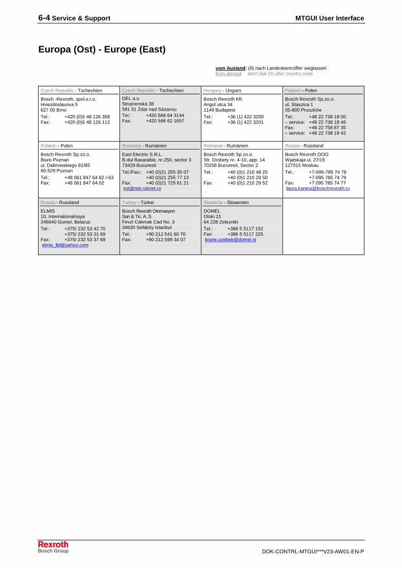
6-4 Service & Support MTGUI User Interface
DOK-CONTRL-MTGUI***V23-AW01-EN-P
Europa (Ost) - Europe (East)
vom Ausland: (0) nach Landeskennziffer weglassen
from abroad: don’t dial (0) after country code
Czech Republic - Tschechien
Bosch -Rexroth, spol.s.r.o.Hviezdoslavova 5627 00 Brno
Tel.: +420 (0)5 48 126 358Fax: +420 (0)5 48 126 112
Czech Republic - Tschechien
DEL a.s.Strojírenská 38591 01 Zdar nad SázavouTel.: +420 566 64 3144Fax: +420 566 62 1657
Hungary - Ungarn
Bosch Rexroth Kft.Angol utca 341149 Budapest
Tel.: +36 (1) 422 3200Fax: +36 (1) 422 3201
Poland – Polen
Bosch Rexroth Sp.zo.o.ul. Staszica 105-800 Pruszków
Tel.: +48 22 738 18 00– service: +48 22 738 18 46Fax: +48 22 758 87 35– service: +48 22 738 18 42
Poland – Polen
Bosch Rexroth Sp.zo.o.Biuro Poznanul. Dabrowskiego 81/8560-529 Poznan
Tel.: +48 061 847 64 62 /-63Fax: +48 061 847 64 02
Romania - Rumänien
East Electric S.R.L.B-dul Basarabie, nr.250, sector 373429 Bucuresti
Tel./Fax:: +40 (0)21 255 35 07+40 (0)21 255 77 13
Fax: +40 (0)21 725 61 21 [email protected]
Romania - Rumänien
Bosch Rexroth Sp.zo.o.Str. Drobety nr. 4-10, app. 1470258 Bucuresti, Sector 2
Tel.: +40 (0)1 210 48 25+40 (0)1 210 29 50
Fax: +40 (0)1 210 29 52
Russia - Russland
Bosch Rexroth OOOWjatskaja ul. 27/15127015 Moskau
Tel.: +7-095-785 74 78+7-095 785 74 79
Fax: +7 095 785 74 77 [email protected]
Russia - Russland
ELMIS10, Internationalnaya246640 Gomel, BelarusTel.: +375/ 232 53 42 70
+375/ 232 53 21 69Fax: +375/ 232 53 37 69 [email protected]
Turkey - Türkei
Bosch Rexroth OtomasyonSan & Tic. A..S.Fevzi Cakmak Cad No. 334630 Sefaköy IstanbulTel.: +90 212 541 60 70Fax: +90 212 599 34 07
Slowenia - Slowenien
DOMELOtoki 2164 228 ZeleznikiTel.: +386 5 5117 152Fax: +386 5 5117 225 [email protected]
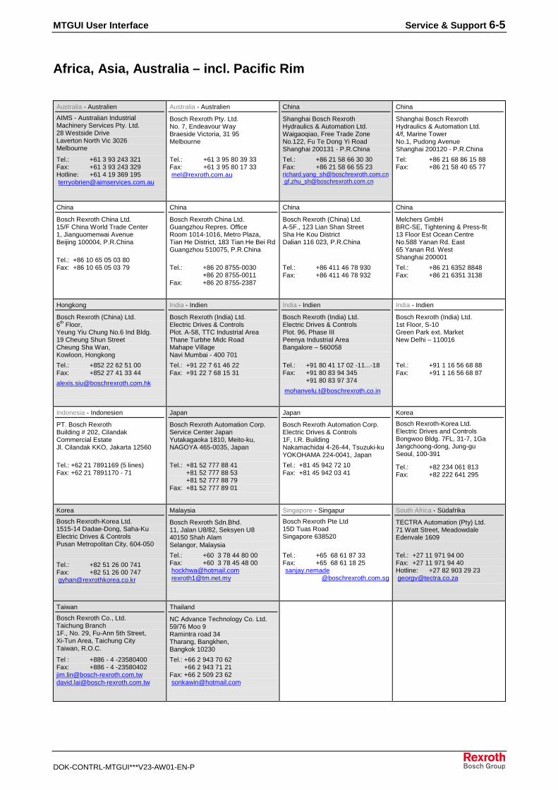
MTGUI User Interface Service & Support 6-5
DOK-CONTRL-MTGUI***V23-AW01-EN-P
Africa, Asia, Australia – incl. Pacific Rim
Australia - Australien
AIMS - Australian IndustrialMachinery Services Pty. Ltd.28 Westside DriveLaverton North Vic 3026Melbourne
Tel.: +61 3 93 243 321Fax: +61 3 93 243 329Hotline: +61 4 19 369 195 [email protected]
Australia - Australien
Bosch Rexroth Pty. Ltd.No. 7, Endeavour WayBraeside Victoria, 31 95Melbourne
Tel.: +61 3 95 80 39 33Fax: +61 3 95 80 17 33 [email protected]
China
Shanghai Bosch RexrothHydraulics & Automation Ltd.Waigaoqiao, Free Trade ZoneNo.122, Fu Te Dong Yi RoadShanghai 200131 - P.R.China
Tel.: +86 21 58 66 30 30Fax: +86 21 58 66 55 [email protected] [email protected]
China
Shanghai Bosch RexrothHydraulics & Automation Ltd.4/f, Marine TowerNo.1, Pudong AvenueShanghai 200120 - P.R.China
Tel: +86 21 68 86 15 88Fax: +86 21 58 40 65 77
China
Bosch Rexroth China Ltd.15/F China World Trade Center1, Jianguomenwai AvenueBeijing 100004, P.R.China
Tel.: +86 10 65 05 03 80Fax: +86 10 65 05 03 79
China
Bosch Rexroth China Ltd.Guangzhou Repres. OfficeRoom 1014-1016, Metro Plaza,Tian He District, 183 Tian He Bei RdGuangzhou 510075, P.R.China
Tel.: +86 20 8755-0030+86 20 8755-0011
Fax: +86 20 8755-2387
China
Bosch Rexroth (China) Ltd.A-5F., 123 Lian Shan StreetSha He Kou DistrictDalian 116 023, P.R.China
Tel.: +86 411 46 78 930Fax: +86 411 46 78 932
China
Melchers GmbHBRC-SE, Tightening & Press-fit13 Floor Est Ocean CentreNo.588 Yanan Rd. East65 Yanan Rd. WestShanghai 200001
Tel.: +86 21 6352 8848Fax: +86 21 6351 3138
Hongkong
Bosch Rexroth (China) Ltd.6th
Floor,Yeung Yiu Chung No.6 Ind Bldg.19 Cheung Shun StreetCheung Sha Wan,Kowloon, Hongkong
Tel.: +852 22 62 51 00Fax: +852 27 41 33 44
India - Indien
Bosch Rexroth (India) Ltd.Electric Drives & ControlsPlot. A-58, TTC Industrial AreaThane Turbhe Midc RoadMahape VillageNavi Mumbai - 400 701
Tel.: +91 22 7 61 46 22Fax: +91 22 7 68 15 31
India - Indien
Bosch Rexroth (India) Ltd.Electric Drives & ControlsPlot. 96, Phase IIIPeenya Industrial AreaBangalore – 560058
Tel.: +91 80 41 17 02 -11...-18Fax: +91 80 83 94 345
+91 80 83 97 374
India - Indien
Bosch Rexroth (India) Ltd.1st Floor, S-10Green Park ext. MarketNew Delhi – 110016
Tel.: +91 1 16 56 68 88Fax: +91 1 16 56 68 87
Indonesia - Indonesien
PT. Bosch RexrothBuilding # 202, CilandakCommercial EstateJl. Cilandak KKO, Jakarta 12560
Tel.: +62 21 7891169 (5 lines)Fax: +62 21 7891170 - 71
Japan
Bosch Rexroth Automation Corp.Service Center JapanYutakagaoka 1810, Meito-ku,NAGOYA 465-0035, Japan
Tel.: +81 52 777 88 41+81 52 777 88 53+81 52 777 88 79
Fax: +81 52 777 89 01
Japan
Bosch Rexroth Automation Corp.Electric Drives & Controls1F, I.R. BuildingNakamachidai 4-26-44, Tsuzuki-kuYOKOHAMA 224-0041, Japan
Tel.: +81 45 942 72 10Fax: +81 45 942 03 41
Korea
Bosch Rexroth-Korea Ltd.Electric Drives and ControlsBongwoo Bldg. 7FL, 31-7, 1GaJangchoong-dong, Jung-guSeoul, 100-391
Tel.: +82 234 061 813Fax: +82 222 641 295
Korea
Bosch Rexroth-Korea Ltd.1515-14 Dadae-Dong, Saha-KuElectric Drives & ControlsPusan Metropolitan City, 604-050
Tel.: +82 51 26 00 741Fax: +82 51 26 00 747 [email protected]
Malaysia
Bosch Rexroth Sdn.Bhd.11, Jalan U8/82, Seksyen U840150 Shah AlamSelangor, Malaysia
Tel.: +60 3 78 44 80 00Fax: +60 3 78 45 48 00 [email protected] [email protected]
Singapore - Singapur
Bosch Rexroth Pte Ltd15D Tuas RoadSingapore 638520
Tel.: +65 68 61 87 33Fax: +65 68 61 18 25 sanjay.nemade
@boschrexroth.com.sg
South Africa - Südafrika
TECTRA Automation (Pty) Ltd.71 Watt Street, MeadowdaleEdenvale 1609
Tel.: +27 11 971 94 00Fax: +27 11 971 94 40Hotline: +27 82 903 29 23 [email protected]
Taiwan
Bosch Rexroth Co., Ltd.Taichung Branch1F., No. 29, Fu-Ann 5th Street,Xi-Tun Area, Taichung CityTaiwan, R.O.C.
Tel : +886 - 4 -23580400Fax: +886 - 4 [email protected]@bosch-rexroth.com.tw
Thailand
NC Advance Technology Co. Ltd.59/76 Moo 9Ramintra road 34Tharang, Bangkhen,Bangkok 10230
Tel.: +66 2 943 70 62 +66 2 943 71 21Fax: +66 2 509 23 62 [email protected]
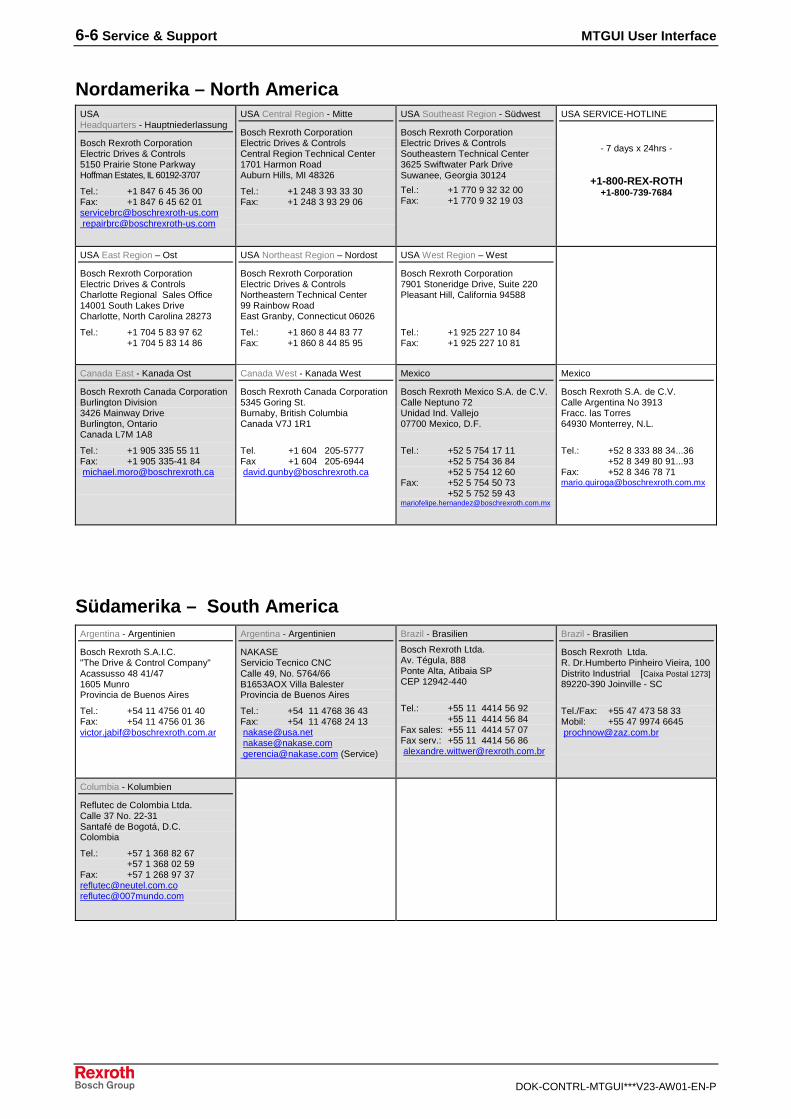
6-6 Service & Support MTGUI User Interface
DOK-CONTRL-MTGUI***V23-AW01-EN-P
Nordamerika – North AmericaUSAHeadquarters - Hauptniederlassung
Bosch Rexroth CorporationElectric Drives & Controls5150 Prairie Stone ParkwayHoffman Estates, IL 60192-3707
Tel.: +1 847 6 45 36 00Fax: +1 847 6 45 62 [email protected] [email protected]
USA Central Region - Mitte
Bosch Rexroth CorporationElectric Drives & ControlsCentral Region Technical Center1701 Harmon RoadAuburn Hills, MI 48326
Tel.: +1 248 3 93 33 30Fax: +1 248 3 93 29 06
USA Southeast Region - Südwest
Bosch Rexroth CorporationElectric Drives & ControlsSoutheastern Technical Center3625 Swiftwater Park DriveSuwanee, Georgia 30124
Tel.: +1 770 9 32 32 00Fax: +1 770 9 32 19 03
USA SERVICE-HOTLINE
- 7 days x 24hrs -
+1-800-REX-ROTH+1-800-739-7684
USA East Region – Ost
Bosch Rexroth CorporationElectric Drives & ControlsCharlotte Regional Sales Office14001 South Lakes DriveCharlotte, North Carolina 28273
Tel.: +1 704 5 83 97 62+1 704 5 83 14 86
USA Northeast Region – Nordost
Bosch Rexroth CorporationElectric Drives & ControlsNortheastern Technical Center99 Rainbow RoadEast Granby, Connecticut 06026
Tel.: +1 860 8 44 83 77Fax: +1 860 8 44 85 95
USA West Region – West
Bosch Rexroth Corporation7901 Stoneridge Drive, Suite 220Pleasant Hill, California 94588
Tel.: +1 925 227 10 84Fax: +1 925 227 10 81
Canada East - Kanada Ost
Bosch Rexroth Canada CorporationBurlington Division3426 Mainway DriveBurlington, OntarioCanada L7M 1A8
Tel.: +1 905 335 55 11Fax: +1 905 335-41 84 [email protected]
Canada West - Kanada West
Bosch Rexroth Canada Corporation5345 Goring St.Burnaby, British ColumbiaCanada V7J 1R1
Tel. +1 604 205-5777Fax +1 604 205-6944 [email protected]
Mexico
Bosch Rexroth Mexico S.A. de C.V.Calle Neptuno 72Unidad Ind. Vallejo07700 Mexico, D.F.
Tel.: +52 5 754 17 11+52 5 754 36 84+52 5 754 12 60
Fax: +52 5 754 50 73+52 5 752 59 43
Mexico
Bosch Rexroth S.A. de C.V.Calle Argentina No 3913Fracc. las Torres64930 Monterrey, N.L.
Tel.: +52 8 333 88 34...36+52 8 349 80 91...93
Fax: +52 8 346 78 [email protected]
Südamerika – South AmericaArgentina - Argentinien
Bosch Rexroth S.A.I.C."The Drive & Control Company"Acassusso 48 41/471605 MunroProvincia de Buenos Aires
Tel.: +54 11 4756 01 40Fax: +54 11 4756 01 [email protected]
Argentina - Argentinien
NAKASEServicio Tecnico CNCCalle 49, No. 5764/66B1653AOX Villa BalesterProvincia de Buenos Aires
Tel.: +54 11 4768 36 43Fax: +54 11 4768 24 13 [email protected] [email protected] [email protected] (Service)
Brazil - Brasilien
Bosch Rexroth Ltda.Av. Tégula, 888Ponte Alta, Atibaia SPCEP 12942-440
Tel.: +55 11 4414 56 92+55 11 4414 56 84
Fax sales: +55 11 4414 57 07Fax serv.: +55 11 4414 56 86 [email protected]
Brazil - Brasilien
Bosch Rexroth Ltda.R. Dr.Humberto Pinheiro Vieira, 100Distrito Industrial [Caixa Postal 1273]89220-390 Joinville - SC
Tel./Fax: +55 47 473 58 33Mobil: +55 47 9974 6645 [email protected]
Columbia - Kolumbien
Reflutec de Colombia Ltda.Calle 37 No. 22-31Santafé de Bogotá, D.C.Colombia
Tel.: +57 1 368 82 67+57 1 368 02 59
Fax: +57 1 268 97 [email protected]@007mundo.com

MTGUI User Interface
DOK-CONTRL-MTGUI***V23-AW01-EN-P
Notes
Bosch Rexroth AGElectric Drives and ControlsBgm.-Dr.-Nebel-Str. 297816 Lohr, [email protected]
Printed in GermanyDOK-CONTRL-MTGUI***V23-AW01-EN-P298459