Rexroth 92500
48
A11VO 1/48 Brueninghaus Hydromatik RE 92 500/07.00 Replaces: 03.97 Variable Displacement Pump A11VO for open circuits Sizes 40…260 Series 1 Nominal pressure 350 bar Peak pressure 400 bar A11VO Features RE 92 500/07.00 – Variable displacement pump with axial piston drive swashplate design for hydrostatic drives in open circuits – Designed primarily for use in mobile applications – Pump operation either self-priming, with tank charging or charging pump – A comprehensive range of variable units is available for different control functions – Power can be adjusted from the outside, even when the machine is running – The through drive is suitable for attachment of gear pumps and axial piston pumps up to the same size, i.e. 100% through drive – The volume flow is adjustable in proportion to the drive speed and displacement and is infinitely variable from q V max to q V min = 0 Index Features 1 Ordering Code / Standard Program 2...3 Technical Data 4...6 LR Power Control 7 LRD Power Control with Pressure Cut-off 8 LRS Power Control with Load Sensing 9 LR... Power Control with Stroke Limiter 10...11 LR... Power Control with Override 12...13 DR Pressure Control 14...15 HD Hydraulic Control, Pilot Pressure Dependent 16 EP Electric Control with Proportional Solenoid 17 Unit Dimensions Size 40 18...20 Unit Dimensions Size 60 21...23 Unit Dimensions Size 75 24...26 Unit Dimensions Size 95 27...29 Unit Dimensions Size 130 30...33 Unit Dimensions Size 190 34...37 Unit Dimensions Size 260 38...41 Through Drive Dimensions 42...43 Overview of A11VO Attachments 44 Pump Combinations A11VO + A11VO 44 Permissible Input or Through Drive Torque 45 Swivel Angle Display 46 Installation and Commissioning Notes 47 Preferred Types 48
-
Upload
elvis-ccala -
Category
Documents
-
view
342 -
download
6
Transcript of Rexroth 92500
A11VO 1/48
BrueninghausHydromatik
RE 92 500/07.00
Replaces: 03.97
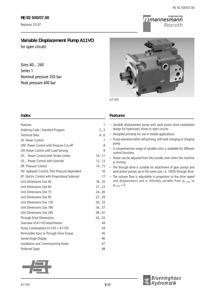
Variable Displacement Pump A11VOfor open circuits
Sizes 40…260Series 1Nominal pressure 350 barPeak pressure 400 bar
A11VO
Features
RE 92 500/07.00
– Variable displacement pump with axial piston drive swashplatedesign for hydrostatic drives in open circuits
– Designed primarily for use in mobile applications
– Pump operation either self-priming, with tank charging or chargingpump
– A comprehensive range of variable units is available for differentcontrol functions
– Power can be adjusted from the outside, even when the machineis running
– The through drive is suitable for attachment of gear pumps andaxial piston pumps up to the same size, i.e. 100% through drive
– The volume flow is adjustable in proportion to the drive speedand displacement and is infinitely variable from qV max toqV min = 0
Index
Features 1
Ordering Code / Standard Program 2...3
Technical Data 4...6
LR Power Control 7
LRD Power Control with Pressure Cut-off 8
LRS Power Control with Load Sensing 9
LR... Power Control with Stroke Limiter 10...11
LR... Power Control with Override 12...13
DR Pressure Control 14...15
HD Hydraulic Control, Pilot Pressure Dependent 16
EP Electric Control with Proportional Solenoid 17
Unit Dimensions Size 40 18...20
Unit Dimensions Size 60 21...23
Unit Dimensions Size 75 24...26
Unit Dimensions Size 95 27...29
Unit Dimensions Size 130 30...33
Unit Dimensions Size 190 34...37
Unit Dimensions Size 260 38...41
Through Drive Dimensions 42...43
Overview of A11VO Attachments 44
Pump Combinations A11VO + A11VO 44
Permissible Input or Through Drive Torque 45
Swivel Angle Display 46
Installation and Commissioning Notes 47
Preferred Types 48

RE 92 500/07.00
Brueninghaus Hydromatik 2/48 A11VO
Ordering Code / Standard Program
FluidMineral oil (no short code)
Axial piston unitVariable displacement, swashplate design A11V
Charging pump (impeller) 40 60 75 95 130 190 260without charging pump (no short code)with charging pump – – – – L
Operating modePump, open circuits O
Size=̂ Displacement Vg max (cm3) 40 60 75 95 130 190 260
Control devices 40 60 75 95 130 190 260Power control LR LR
with override cross-sensing LR C LR.Chigh pressure dependent LR3 LR3pilot pressure dependent, negative LG1 LG1pilot pressure dependent, positive LG2 LG2with 12V solenoid, negative LE1 LE1with 24V solenoid, negative LE2 LE2
with pressure cut-off D L. D . .2-stage E L. E . .remote controlled G L. . G .
with load sensing S L. . . Selectric override S2 L. . . S2hydraulic override S5 L. . . S5
with stroke limiter negative control ∆p = 25 bar H1 L. . . H1negative control ∆p = 10 bar H5 L. . . H5positive control ∆p = 25 bar H2 L. . . H2positive control ∆p = 10 bar H6 L. . . H6positive control U = 12 V U1 L. . . U1positive control U = 24 V U2 L. . . U2
Pressure control DR DRwith load sensing DRS DRSremote controlled DRG DRGfor parallel operation DRL DRL
Hydraulic control, ∆p = 10 bar HD1 HD1pilot pressure dependent ∆p = 25 bar HD2 HD2
with pressure cut-off D HD.Dwith pressure cut-off, remote controlled G HD.G
Electric control, U = 12 V EP1 EP1with proportional solenoid U = 24 V EP2 EP2
with pressure cut-off D EP.Dwith pressure cut-off, remote controlled G EP.G
For controls with several additional functions, follow the order of the columns. Only one option possible in each column (e.g. LRDCH2).Note that the following combinations are not possible with the power control:…GS, …GS2, …GS5, …EC and the combination …DG in conjunction with stroke limiters H1, H2, H5, H6, U1 and U2.
= available= available on request = preferred program (preferred types see page 48)
– = not available
A11VO 3/48 Brueninghaus Hydromatik
RE 92 500/07.00
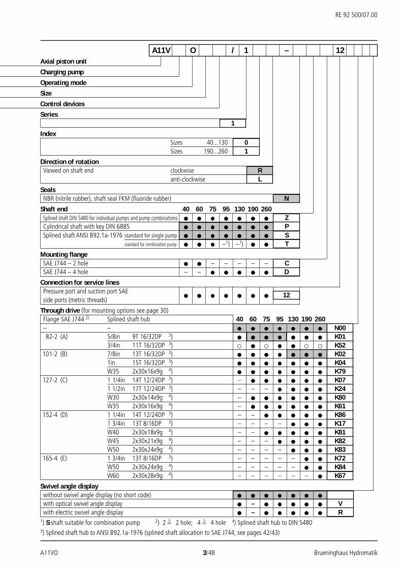
A11V O / 1 – 12Axial piston unit
Charging pump
Operating mode
Size
Control devices
Series1
IndexSizes 40...130 0Sizes 190...260 1
Direction of rotationViewed on shaft end clockwise R
anti-clockwise L
SealsNBR (nitrile rubber), shaft seal FKM (fluoride rubber) N
Shaft end 40 60 75 95 130 190 260Splined shaft DIN 5480 for individual pumps and pump combinations ZCylindrical shaft with key DIN 6885 PSplined shaft ANSI B92.1a-1976 standard for single pump S
standard for combination pump –1) –1) T
Mounting flangeSAE J744 – 2 hole – – – – – CSAE J744 – 4 hole – – D
Connection for service linesPressure port and suction port SAE 12side ports (metric threads)
Through drive (for mounting options see page 30)Flange SAE J744 2) Splined shaft hub 40 60 75 95 130 190 260– – N0082-2 (A) 5/8in 9T 16/32DP 3) K01
3/4in 11T 16/32DP 3) K52101-2 (B) 7/8in 13T 16/32DP 3) K02
1in 15T 16/32DP 3) K04W35 2x30x16x9g 4) K79
127-2 (C) 1 1/4in 14T 12/24DP 3) – K071 1/2in 17T 12/24DP 3) – – – K24W30 2x30x14x9g 4) – K80W35 2x30x16x9g 4) – K61
152-4 (D) 1 1/4in 14T 12/24DP 3) – – K861 3/4in 13T 8/16DP 3) – – – – K17W40 2x30x18x9g 4) – – K81W45 2x30x21x9g 4) – – – K82W50 2x30x24x9g 4) – – – – K83
165-4 (E) 1 3/4in 13T 8/16DP 3) – – – – – K72W50 2x30x24x9g 4) – – – – – K84W60 2x30x28x9g 4) – – – – – – K67
Swivel angle displaywithout swivel angle display (no short code)with optical swivel angle display – Vwith electric swivel angle display – R
1) S shaft suitable for combination pump 2) 2 =̂ 2 hole; 4 =̂ 4 hole 4) Splined shaft hub to DIN 54803) Splined shaft hub to ANSI B92.1a-1976 (splined shaft allocation to SAE J744, see pages 42/43)

RE 92 500/07.00
Brueninghaus Hydromatik 4/48 A11VO
Technical Data
Hydraulic Fluid
We request that before starting a project, detailed information aboutthe choice of hydraulic fluids and application conditions are takenfrom our catalogue sheets RE 90220 (mineral oil), RE 90221(environmentally acceptable hydraulic oils) and RE 90223 (HFhydraulic fluids).
The A11VO variable displacement pump is not suitable for operationwith HFA, HFB and HFC. When operating with HFD or environmentallyacceptable hydraulic fluids, restrictions in the technical data shouldbe noted – please contact us (the hydraulic fluid used should bestated in clear text in the order).
Operating viscosity range
We recommend that the operating viscosity (at operatingtemperature), for both the efficiency and life of the unit, be chosenwithin the optimum range of:
νopt = opt. operating viscosity 16…36 mm2/s
referred to tank temperature (open circuit).
Viscosity limits
The limiting values for viscosity are as follows:
νmin = 5 mm2/s
short term, at a max. permissible leakage oil temperature tmax = 115°C
νmax = 1600 mm2/s short term, on cold start (tmin = -40°C)
Please note that the max. fluid temperature is also not exceeded incertain areas (for instance bearing area).
At temperatures of –25°C to –40°C special measures may be required.Please contact us for further information.
Selection diagram
Notes on the selection of hydraulic fluid
In order to select the correct fluid, it is necessary to know the operatingtemperature in the tank (open circuit) in relation to the ambienttemperature.
The hydraulic fluid should be selected so that within the operatingtemperature range, the operating viscosity lies within the optimumrange (νopt) (see shaded section of the selection diagram). Werecommend that the higher viscosity grade is selected in each case.
Example: At an ambient temperature of X°C, the operatingtemperature in the tank is 60°C. In the optimum viscosity range νopt
(shaded area), this corresponds to viscosity grades VG 46 or VG 68.VG 68 should be selected.
Important: The leakage oil temperature is influenced by pressureand speed and is typically higher than the tank temperature. However,maximum temperature at any point in the system must be less than115°C.
Please consult Brueninghaus Hydromatik if the above conditionscannot be kept at extreme operating parameters or because of highambient temperature.
5
10
40
60
20
100
200
400600
100016002500 0° 20° 40° 60° 80° 100°-40° -20°
16
36
5
1600
-40° -25° -10° 10° 30° 50° 90° 115°70°0°
VG 22VG 32VG 46VG 68VG 100
Visc
osity
ν in
mm
2 /s
Temperature t in °C
tmax = +115°Ctmin = -40°C
νopt.
Fluid temperature range

A11VO 5/48 Brueninghaus Hydromatik
RE 92 500/07.00
FiltrationThe finer the filtration, the better the achieved purity grade of thehydraulic fluid and the longer the life of the axial piston unit.
To ensure the functioning of the axial piston unit, a minimum puritygrade of
9 to NAS 1638
18/15 to ISO/DIS 4406 is necessary.
At very high hydraulic fluid temperatures, a minimum purity grade of
8 to NAS 1638
17/14 to ISO/DIS 4406 is necessary.
If the above mentioned grades cannot be maintained, please consultus.
Input operating pressure range
Absolute pressure at port S (suction port)
Version without charging pump
pabs min _____________________________________________________ 0,8 bar
pabs max ______________________________________________________ 30 bar
Please consult us if the pressure is > 5 bar.
Version with charging pump
pabs min _____________________________________________________ 0,6 bar
pabs max _______________________________________________________ 2 bar
Output operating pressure rangePressure at port A or B
Nominal pressure pN ______________________________________ 350 bar
Peak pressure pmax ________________________________________ 400 bar
Case drain pressure
Maximum permissible pressure of the leakage fluid at ports T1 and T2
pL _______________________________________________________ 2 bar abs.
A drain oil line to the tank is necessary.
Flushing the housing
If a variable displacement pump with variable displacement units EP,HD, DR or with stroke limiter (H., U.) is operated for an extendedperiod (t > 10 min) with zero volume flow or operating pressure <15 bar, the housing should be flushed via one of the ports T1, T2 or Rto avoid overheating.
NG 40 60 75 95 130 190 260
qV flush (L/min) 2 3 3 4 4 5 6
It is not necessary to flush the housing on the version withcharging pump (A11VLO).
Technical Data
1,2
1,1
1,0
0,90,8 0,9 1,0
Displacement Vg / Vg max
Spee
d n m
ax /
n max
1 pabs = 1,5 bar
pabs = 1 bar
Maximum permissible speed (speed limit)Permissible speed due to increasing the input pressure pabs at suctionport S or if Vg < Vg max
Shaft seal temperature range
The FPM shaft seal is suitable for housing temperatures of –25°C to+115°C.
Note:
An NBR shaft seal is required for applications below –25°C(permissible temperature range: -40°C to +90°C).
Please state NBR shaft seal in clear text when ordering.
Charging pumpThe charging pump is a centrifugal pump. Its role is to charge theA11VO, enabling it to run at higher speeds. It also makes cold startingeasier at low temperatures and high hydraulic fluid viscosity.
Tank charging is never required.
M A G
S M1
Vg max Vg min
R T1 T2

RE 92 500/07.00
Brueninghaus Hydromatik 6/48 A11VO
Technical Data
Table of values, (theoretical values, regardless of ηmh and ηv’; approximate values)Size A11VO 40 60 75 95 130 190 260
A11VLO (with charging pump) 130 190 260
Displacement Vg max cm3 42 58,3 74 93,8 130 192,7 260 130 192,7 260
Vg min cm3 0 0 0 0 0 0 0 0 0 0
Max. speed 1)
at Vg maxnmax min–1 3000 2700 2550 2350 2100 2100 1800 2500 2) 2500 2) 2300 2)
Max. speed 3)at Vg ≤ Vg max
nmax min-1 3500 3250 3000 2780 2500 2500 2300 2500 2500 2300
Flow 4)at nmax und Vg max
qV max L/min 122 153 183 214 265 393 454 315 467 580
Power at qV max
and ∆p = 350 bar Pmax kW 73 92 110 129 159 236 273 190 281 349
Torque at Vg max
and ∆p = 350 bar Tmax Nm 234 324 412 522 724 1073 1448 724 1073 1448
Moment of inertiaabout the drive axis J kgm2 0,0048 0,0082 0,0115 0,0173 0,0318 0,055 0,0878 0,0337 0,0577 0,0895
Weight (approx.) m kg 28 36 45 53 66 95 125 69 100 1301) The values are quoted for an absolute pressure (pabs) of 1 bar at suction port S and mineral fluid.2) The values are quoted for an absolute pressure (pabs) of at least 0.8 bar at suction port S and mineral operating fluid.3) The values are quoted for Vg < Vg max or increase of the input pressure pabs at suction port S (see graph on page 5).4) Allows for 3% displacement loss.
Determination of size
Vg • n • ηvFlow qV= in L/min1000
Vg • ∆p 1,59 • Vg • ∆pDrive torque T = = in Nm
20 • π • ηmh 100 • ηmh
2π • T • n T • n qV • ∆pDrive power P = = = in kW
60000 9549 600 • ηt
Drive
Permissible radial and axial loading of driveSize 40 60 75 95 130 190 260
Distance of Fq a mm 17,5 17,5 20 20 22,5 26 29
(from shaft collar) b mm 30 30 35 35 40 46 50
c mm 42,5 42,5 50 50 57,5 66 71
Max. permissible radial force a Fq max N 3600 5000 6300 8000 11 000 16 925 22 000at b Fq max N 2891 4046 4950 6334 8594 13 225 16 809
c Fq max N 2416 3398 4077 5242 7051 10 850 13 600
Max. permissible axial force ± Fax max N 1500 2200 2750 3500 4800 6000 4150
Vg = geometric displacement per revolution in cm3
∆p = differential pressure in bar
n = speed in rpm
ηv = volumetric efficiency
ηmh = mechanical-hydraulic efficiency
ηt = total efficiency (ηt = ηv • ηmh)
Fq
a, b, c
-+
Fax
A11VO 7/48 Brueninghaus Hydromatik
RE 92 500/07.00
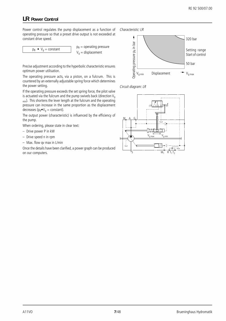
Power control regulates the pump displacement as a function ofoperating pressure so that a preset drive output is not exceeded atconstant drive speed.
Precise adjustment according to the hyperbolic characteristic ensuresoptimum power utilisation.
The operating pressure acts, via a piston, on a fulcrum. This iscountered by an externally adjustable spring force which determinesthe power setting.
If the operating pressure exceeds the set spring force, the pilot valveis actuated via the fulcrum and the pump swivels back (direction Vg
min). This shortens the lever length at the fulcrum and the operatingpressure can increase in the same proportion as the displacementdecreases (pB•Vg = constant).
The output power (characteristic) is influenced by the efficiency ofthe pump.
When ordering, please state in clear text:
– Drive power P in kW
– Drive speed n in rpm
– Max. flow qv max in L/min
Once the details have been clarified, a power graph can be producedon our computers.
LR Power Control
pB = operating pressure
Vg = displacement
320 bar
50 bar
Circuit diagram: LR
Displacement
Setting rangeStart of control
Oper
atin
g pr
essu
re p
B in
bar
Vg maxVg min
pB • Vg = constant
M A G
S M1
Vg max Vg min
R T1 T2
Characteristic: LR

RE 92 500/07.00
Brueninghaus Hydromatik 8/48 A11VO
LRD Power Control with Pressure Cut-off
350
50
Setting range
Circuit diagram: LRD
Displacement
Ope
ratin
g pr
essu
re p
B in
bar
Vg maxVg min
max
min
M A G
S M1
Vg max Vg min
R T1 T2
LRD Power control with pressure cut-off
Pressure cut-off corresponds to a pressure control which adjusts thepump displacement back to Vg min when the set pressure signal valueis reached.
This function overrides power control, i.e. below the pressure signalvalue, the power control function is performed.
The valve is integrated into the control housing and is permanentlyset to a pressure signal value at the factory.
Setting range 50 to 350 bar.
Characteristic: LRD
LRE Power control with 2-stage pressure cut-off
Sequencing an external pilot pressure at port Y allows the basicpressure cut-off value to be increased by 50+20 bar and a secondpressure setting to be implemented. This value is higher than thesetting value of the primary pressure relief valve and thus switchesoff pressure cut-off. The pressure signal at port Y must be between20 and 50 bar.
Y
M A G
S M1
Vg max Vg min
R T1 T2
Circuit diagram: LRE
Characteristic: LRE
350
370
390
320
Ope
ratin
g pr
essu
re p
B in
bar
Displacement Vg maxVg min
Increased pressure cut-off=̂ Pressure cut-off switched offPrimary pressure relief valve
Basic pressure cut-off value

A11VO 9/48 Brueninghaus Hydromatik
RE 92 500/07.00
LRS Power Control with Load Sensing
LRDS Power control with pressure cut-offand load sensing
The load sensing control works as a flow controller controlled byload pressure and co-ordinates the pump displacement to the quantityrequired by the actuator.
The pump flow depends on the external orifice (control block, throttlevalve) switched between the pump and the actuator, but is not affectedby the load pressure over the whole range below the pressure signalvalue.
The valve compares the pressure upstream of the orifice with thedownstream pressure and keeps the pressure drop (differentialpressure ∆p) occurring here, and hence the flow, constant.
If the differential pressure rises, the pump is swivelled back (directionVg min). If the differential pressure ∆p drops, the pump is swivelledout (direction Vg max) until balance is restored in the valve.
∆porifice = ppump – pactuator
The setting range for ∆p is between 14 bar and 25 bar.
The standard setting is 18 bar (please state in clear text).
The stand-by pressure in zero stroke mode (orifice closed) is slightlyhigher than the ∆p-setting.
Power control and pressure cut-off override the load sensing control,i.e. the load sensing function is performed below the set hyperboliccharacteristic and below the set pressure signal value.
In a standard LS system, pressure cut-off is integrated into the pumpcontrol. In an LUDV system, pressure cut-off is integrated into theLUDV valve block.
(1) The orifice (throttle valve) is not included in the supply.
Displacement
Ope
ratin
g pr
essu
re p
B in
bar
Vg maxVg min
Circuit diagram: LRDS
M
X
A G
S M1
Vg max Vg min
R T1T2
X Z4
M A G
S M1
Vg max Vg min
R T1 T2
Circuit diagram: LRS5
LRS5 Power control with load sensing,with hydraulic override
By sequencing an external pilot pressure at port Z, the differentialpressure ∆p of the load sensing control can be proportionallyoverridden.
An example of this is shown in the characteristic below. Please consultus when planning your system.
Characteristic: LRS
Characteristic: LRS5
0 5
25
1814105
13
26
10 15 20 25 30
∆pLS
in b
ar
Pilot pressure pz in bar
(1)
(1)

RE 92 500/07.00
Brueninghaus Hydromatik 10/48 A11VO
LR... Power Control with Stroke Limiter
Circuit diagram: LRU1/2
LR... Power control with stroke limiter
The stroke limiter enables the pump displacement to be infinitelyvaried or limited across the whole setting range. The displacement isset once proportionally by the pilot current applied at the proportio-nal solenoid or the pilot pressure … applied at port Y (max. 40 bar).Direct current at 12V (U1) or 24V (U2) respectively is required totrigger the proportional solenoid (insulation IP 54).
The stroke limiter is overridden by the power control, i.e. below thepower control characteristic (hyperbolic characteristic) thedisplacement is set according to the pilot current or pilot pressure. Ifthe power control characteristic is exceeded by the flow set or theoperating pressure, the power control overrides and readjusts thedisplacement according to the hyperbolic characteristic.
To swivel the pump out of its initial position Vg max towards Vg min, apositioning pressure of 30 bar is needed with the electric stroke limiterLRU1/2 and the hydraulic stroke limiter LRH2/6.
The necessary positioning oil is taken from the high pressure or fromthe external positioning pressure available at port G (> 30 bar).
If the operating pressure is > 30 bar and Vg min > 0, no externalpositioning pressure is required. In this case the change-over valveshould be removed from the pump before commissioning (see notein repair instructions RDE 92500-R) and port G should be closed.
800
600
400
200
0 1,00,5
Pilo
t cur
rent
I in
mA
Characteristic: LRU2
LRU1/2 Power control with electric strokelimiter (positive control)
Control from Vg min to Vg max
As the pilot current increases, the pump swivels to a higherdisplacement.
Start of control at approx.: 400 mA (12 V) 200 mA (24 V)
End of control at approx.: 1200 mA (12 V) 600 mA (24 V)
Starting position in unpressurised state: Vg max
At operating pressure > 30 bar the pump swivels from Vg max towardsVg min (pilot current < start of control)
The following are available to trigger the proportional solenoid:
– Proportional amplifier PV ________________ (see RE 95023)
– Proportional amplifier VT 2000 ___________ (see RE 29904)
– Chopper amplifier CV ___________________ (see RE 95029)
– Microcontroller MC ____________________ (see RE 95050)
Displacement Vg maxVg min
M A G
S M1
Vg max Vg min
R T1 T2

A11VO 11/48 Brueninghaus Hydromatik
RE 92 500/07.00
LR... Power Control with Stroke Limiter
353025201510
4
0 1,00,5
201510
4
0 1,00,5
Pilo
t pre
ssur
e p S
t in
bar
Setti
ng ra
nge
Pilo
t pre
ssur
e p S
t in
bar
Setti
ng ra
nge
Characteristic: H6
Pilot pressure rise (Vg min – Vg max) ___________ ∆p = 10 bar
Circuit diagram: LRH2, LRH6
Characteristic: H2
Pilot pressure rise (Vg min – Vg max) ___________ ∆p= 25 bar
Pilo
t pre
ssur
e p S
t in
bar
Setti
ng ra
nge
Characteristic: H5
Pilot pressure rise (Vg max – Vg min) ___________ ∆p = 10 bar
Pilo
t pre
ssur
e p S
t in
bar
Setti
ng ra
nge
Circuit diagram: LRH1, LRH5
Characteristic: H1
Pilot pressure rise (Vg max – Vg min) ___________ ∆p = 25 bar
353025201510
4
0 1,00,5
201510
4
0 1,00,5
LRH2/6 Hydraulic stroke limiter (positive control)
Control from Vg min to Vg max
As the pilot pressure rises, the pump swivels to a higher displacement.
Start of control (at Vg min) adjustable _________ from 4 – 10 bar
Please state start of control in clear text when ordering.
Starting position in unpressurised state: Vg max
At operating pressure > 30 bar the pump swivels from Vg max towardsVg min (pilot pressure < start of control)
M
Y
A G
S M1
Vg max Vg min
R T1 T2
M
Y
A G
S M1
Vg max Vg min
R T1T2
LRH1/5 Hydraulic stroke limiter (negative control)
Control from Vg max to Vg min
As the pilot pressure rises, the pump swivels to a smaller displacement.
Start of control (at Vg max) adjustable _________ from 4 – 10 bar
Please state start of control in clear text when ordering.
Starting position in unpressurised state: Vg max
Displacement Vg maxVg min
Displacement Vg maxVg min
Displacement Vg maxVg min
Displacement Vg maxVg min

RE 92 500/07.00
Brueninghaus Hydromatik 12/48 A11VO
Circuit diagram: LR3
Circuit diagram: LRC
LR... Power Control with Override
LRC Override with cross-sensing
Cross-sensing is a total power control (high pressure dependent)which links two A11VO pumps of equal size with LRC control inpower control.
If one pump is running at operating pressures below the set start ofcontrol, the drive power not drawn, in a limit case up to 100%, isavailable to the other pump. Total drive power is thus distributedbetween two actuators as required.
Power released by pressure cut-off or other overrides is disregarded.
Semi cross-sensing functionIf LRC control is used on the first pump (A11VO) and another pumpmounted on the through drive also with power control without cross-sensing, the power required for the second pump is subtracted fromthe first pump in its setting. The second pump has priority in thetotal power setting.
LR3 High pressure dependent override
High pressure dependent power override is a total power controlwhere the power setting is loaded by the operating pressure of anattached fixed displacement pump (port Z).
The A11VO can thus be set to 100% of the total drive power. Thepower setting of the A11VO is reduced in proportion to the load-dependent rise in the operating pressure of the fixed displacementpump. The fixed displacement pump has priority in the total powersetting.
The measuring area for the power reduction is adapted to thedisplacement of the fixed displacement pump.
LE1/2 Electric override (negative)
In this case, in contrast to hydraulic power override, the power settingis loaded by a pilot current. This pilot current acts, via a proportionalsolenoid, against the power control setting spring.
Higher pilot current =̂ power decrease.
Direct current at 12V (E1) or 24V (E2) respectively is required totrigger the proportional solenoid.
The mechanically set basic power setting can be varied by means ofdifferent pilot currents.
If the pilot current signal is variably readjusted via a load limit sen-sing control, the power decrease of all the actuators is adapted tothe possible power output of the diesel engine.
Circuit diagram: LE1, LE2
M
ZpHD
A G
S
LR
M1
Vg max Vg min
R T1 T2
M
Z
A G
S M1
Vg max Vg min
R T1 T2
pHD
M A G
S M1
Vg max Vg min
R T1 T2

A11VO 13/48 Brueninghaus Hydromatik
RE 92 500/07.00
Circuit diagram: LG1
Circuit diagram: LG2
LR... Power Control with Override
LR3LRC
LG2
LG1LE1/2
pHD I
pSt
DisplacementOpe
ratin
g pr
essu
re p
B (b
ar)
Vg max
Controlling the power setting
LG1/2 Pilot pressure dependent override
An external pilot pressure acts via port Z on the power control settingspring.
The mechanically set basic power setting can be varied by means ofdifferent pilot pressure settings.
If the pilot pressure signal is variably readjusted via a load limit sen-sing control, the power decrease of all the actuators is adapted tothe possible power output of the diesel engine.
The pilot pressure used for power control is generated by an externalcontroller which is not part of the A11VO (see also sheet RE 95072,Electronic load limit sensing control for excavators, GLB).
LG1 Negative power override
With negative power override LG1, the force resulting from the pilotpressure acts against the power control setting spring, i.e. higherpilot pressure =̂ power decrease.
LG2 Positive power override
With positive power override LG2, the force resulting from the pilotpressure supports the power control setting spring, i.e. higher pilotpressure =̂ power increase.
Vg min
Z
AM G
S M1
Vg max Vg min
R T1 T2
M
Z
A G
S M1
Vg max Vg min
R T1 T2

RE 92 500/07.00
Brueninghaus Hydromatik 14/48 A11VO
350
300
250
200
150
100
50
0
Circuit diagram: DR
Flow qv in L/min
Setti
ng ra
nge
Oper
atin
g pr
essu
re p
B in
bar
max
. 10
bar
pmax
M A G
S M1
Vg max Vg min
R T1 T2
Characteristic: DR
Flow qv in L/min
Ope
ratin
g pr
essu
re p
B in
bar
Circuit diagram: DRS
M
X
A G
S M1
Vg max Vg min
R T1 T2
DRS Pressure control with load sensing
The load sensing control works as a flow controller controlled byload pressure and co-ordinates the pump displacement to the quantityrequired by the actuator.
The pump flow depends on the external orifice (control block, throttlevalve) switched between the pump and the actuator, but is not affectedby the load pressure over the whole range below the pressure signalvalue.
The valve compares the pressure upstream of the orifice with thedownstream pressure and keeps the pressure drop (differentialpressure ∆p) occurring here, and hence the flow, constant.
If the differential pressure rises, the pump is swivelled back (directionVg min). If the differential pressure ∆p drops, the pump is swivelledout (direction Vg max) until balance is restored in the valve.
∆porifice = ppump - pactuator
The setting range for ∆p is between 14 bar and 25 bar.
The standard setting is 18 bar (please state in clear text).
The stand-by pressure in zero stroke mode (orifice closed) is slightlyhigher than the ∆p setting.
Pressure control overrides the load sensing control, i.e. the load sen-sing function is performed below the set pressure signal value.
(1) The orifice (throttle valve) is not included in the supply.
DR Pressure control
The pressure control maintains constant pressure in a hydraulic systemwithin its control range despite fluctuations in the flow required. Thevariable displacement pump delivers only the amount of hydraulicfluid needed by the actuators. If the operating pressure exceeds thepressure signal value set at the integral valve, the pump isautomatically swivelled back and the closed loop error reduced.
Starting position in unpressurised state: Vg max
Setting range 50 to 350 bar.
Characteristic: DRS
DR Pressure Control
(1)

A11VO 15/48 Brueninghaus Hydromatik
RE 92 500/07.00
DRG Pressure remote control
The pressure remote control enables the pressure control setting tobe overridden by means of a separate pressure relief valve (1) and alower pressure signal value can thus be set.
Setting range 50 to 350 bar.
Alternatively, the system can be started at low operating pressures(stand-by pressure) by actuating a 2-2 way valve (2), also separatelymounted.
Both functions can be carried out separately or in conjunction (seecircuit diagram).
The external valves are not included in the supply.
We recommend that the following is used as the separate pressurerelief valve (1):
DBDH 6 (manual), see RE 25402.
350
300
250
200
150
100
50
0
Circuit diagram : DRL
Oper
atin
g pr
essu
re p
B in
bar
Setti
ng ra
nge m
ax. 1
0 ba
r
pmax
Circuit diagram: DRG
DRL Pressure control for parallel operation
Pressure control DRL is designed for pressure control of several A11VOaxial piston pumps arranged in parallel.
The pressure signal valve for all the pumps connected to the systemcan be preset by means of an external pressure relief valve (1).
Setting range 50 to 350 bar.
Each pump can be disconnected from the system via a 3-2 way valve(2), also separately mounted.
Check valves (3) should as a rule be provided in the main conduit(port A) or control line (port X).
The external valves are not included in the supply.
We recommend that the following is used as the separate pressurerelief valve (1):
DBDH 6 (manual), see RE 25402.
M
X
max
. 5m
A G
S M1
Vg max Vg min
R T1T2
M
X
A G
S M1
Vg max Vg min
R T1 T2
Characteristic: DRG
(1)(2)
(3)(3)
(2) (1)
DR Pressure Control
Flow qv in L/min
RE 92 500/07.00
Brueninghaus Hydromatik 16/48 A11VO
Circuit diagram: HD1D, HD2D
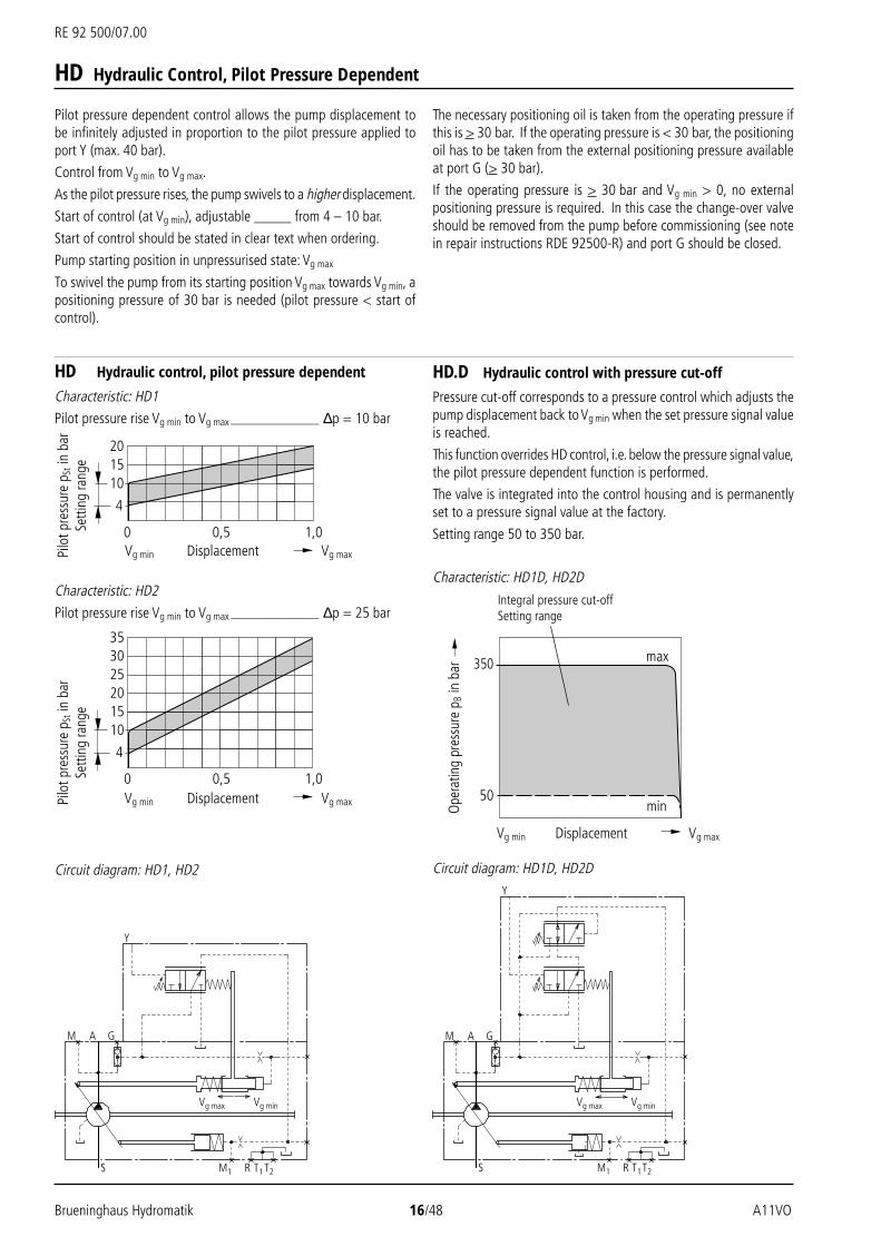
Pilot pressure dependent control allows the pump displacement tobe infinitely adjusted in proportion to the pilot pressure applied toport Y (max. 40 bar).
Control from Vg min to Vg max.
As the pilot pressure rises, the pump swivels to a higher displacement.
Start of control (at Vg min), adjustable _____ from 4 – 10 bar.
Start of control should be stated in clear text when ordering.
Pump starting position in unpressurised state: Vg max
To swivel the pump from its starting position Vg max towards Vg min, apositioning pressure of 30 bar is needed (pilot pressure < start ofcontrol).
Pilo
t pre
ssur
e p S
t in
bar
Setti
ng ra
nge
Pilo
t pre
ssur
e p S
t in
bar
Setti
ng ra
nge
201510
4
0 1,00,5
353025201510
4
0 1,00,5
Circuit diagram: HD1, HD2
M
Y
A G
S M1
Vg max Vg min
R T1T2
M
Y
A G
S M1
Vg max Vg min
R T1T2
350
50
Displacement
Ope
ratin
g pr
essu
re p
B in
bar
Vg maxVg min
Integral pressure cut-offSetting range
max
min
Characteristic: HD1D, HD2D
HD Hydraulic control, pilot pressure dependent
Characteristic: HD1Pilot pressure rise Vg min to Vg max _________________ ∆p = 10 bar
Characteristic: HD2
Pilot pressure rise Vg min to Vg max _________________ ∆p = 25 bar
HD Hydraulic Control, Pilot Pressure Dependent
HD.D Hydraulic control with pressure cut-off
Pressure cut-off corresponds to a pressure control which adjusts thepump displacement back to Vg min when the set pressure signal valueis reached.
This function overrides HD control, i.e. below the pressure signal value,the pilot pressure dependent function is performed.
The valve is integrated into the control housing and is permanentlyset to a pressure signal value at the factory.
Setting range 50 to 350 bar.
The necessary positioning oil is taken from the operating pressure ifthis is > 30 bar. If the operating pressure is < 30 bar, the positioningoil has to be taken from the external positioning pressure availableat port G (> 30 bar).
If the operating pressure is > 30 bar and Vg min > 0, no externalpositioning pressure is required. In this case the change-over valveshould be removed from the pump before commissioning (see notein repair instructions RDE 92500-R) and port G should be closed.
Displacement Vg maxVg min
Displacement Vg maxVg min

A11VO 17/48 Brueninghaus Hydromatik
RE 92 500/07.00
Electric control with proportional solenoid allows the pumpdisplacement to be infinitely set and programmed in proportion tothe solenoid force or current strength. The control force at the controlspool is applied by a proportional solenoid.
Direct current at 12V (EP1) or 24V (EP2) respectively is required totrigger the proportional solenoid (insulation IP 54).
Control from Vg min to Vg max
As the pilot current increases, the pump swivels to a higherdisplacement.
Start of control at approx.: 400 mA (12 V) 200 mA (24 V)
End of control at approx.: 1200 mA (12 V) 600 mA (24 V)
Starting position in unpressurised state: Vg max
To swivel the pump from its starting position Vg max towards Vg min, apositioning pressure of 30 bar is needed (pilot current < start ofcontrol).
The necessary positioning oil is taken from the operating pressure ifthis is > 30 bar. If the operating pressure is < 30 bar, the positioningoil has to be taken from the external positioning pressure availableat port G (> 30 bar).
If the operating pressure is > 30 bar and Vg min > 0, no externalpositioning pressure is required. In this case the change-over valveshould be removed from the pump before commissioning (see notein repair instructions RDE 92500-R) and port G should be closed.
800700600500400300200100
0 0,5 1,0
Pilo
t cur
rent
I in
mA
Circuit diagram: EP
M A G
S M1
Vg max Vg min
R T1 T2
Circuit diagram: EP2D
M A G
S M1
Vg max Vg min
R T1 T2
Characteristic: EP2D
350
50
Displacement
Ope
ratin
g pr
essu
re p
B in
bar
Vg maxVg min
Integral pressure cut-offSetting range
max
min
EP Electric Control with Proportional Solenoid
Characteristic: EP2
Important:
Pump with EP control should be fitted in the tank only if mineralhydraulic fluid is used and the oil temperature in the tank does notexceed 80°C.
The following are available to trigger the proportional solenoid:
– Proportional amplifier PV ________________ (see RE 95023)
– Proportional amplifier VT 2000 ___________ (see RE 29904)
– Chopper amplifier CV___________________ (see RE 95029)
– Microcontroller MC ____________________ (see RE 95050)
EP.D Electric control with pressure cut-off
Pressure cut-off corresponds to a pressure control which adjusts thepump displacement back to Vg min when the set pressure signal valueis reached.
This function overrides EP control, i.e. below the pressure signal value,the pilot current dependent function is performed.
The valve is integrated into the control housing and is permanentlyset to a pressure signal value at the factory.
Setting range 50 to 350 bar.
Displacement Vg maxVg min

RE 92 500/07.00
Brueninghaus Hydromatik 18/48 A11VO
Unit Dimensions Size 40
LRDCS:Power control LR with pressure cut-off D, cross-sensing control C and load sensing control S
Ports
A, B Service port SAE 3/4; 420 bar(6000 psi) High pressure series
S Suction port SAE 2; 210 bar(3000 psi) Standard series
T1, T2 Air bleed, tank M22x1,5; 14 deep
R Air bleed, oil drain M22x1,5; 14 deep
M1 Measuring point, regulating chamber M12x1,5; 12 deep
M Measuring point, service port M12x1,5; 12 deep
X Pilot port M14x1,5; 12 deepfor version with load sensing (S) andremote pressure ct-off control (G)
Y Pilot port M14x1,5; 12 deepfor version with stroke limiter (H...),2-stage pressure cut-off (E) and HD
Z Pilot port M14x1,5; 12 deepfor version with cross-sensing (C) andpower override (LR3, LG1)
G Port for positioning pressure (controller) M14x1,5; 12 deepfor version with stroke limiter (H.., U2),HD and EP with screwed fitting GE10 - PLM(otherwise port G closed)
Shaft endsZSplined shaft DIN 5480W35x2x30x16x9g
TSplined shaft ANSI B92.1a-19761 1/4in 14T 12/24DP 1)(SAE J744 – 32-4 (C))
SSplined shaft ANSI B92.1a-19761in 15T 16/32DP 1)(SAE J744 – 25-4 (B-B))
T1
T1
T2
T1
R
X
X
Z
T2
T2
S
M1W
M
B
S
Z
G
Vg max
Vg min
V Y B(S)
S(A)
B M G
LRCDS
Z
View YClockwise rotation(Anti-clockwise rotation) Detail V
Detail W
M12; 20 deep
M10; 17 deep
1) 30° pressure angle, flat root, side fit, tolerance class 5
Prior to finalising your design, please request certified installation drawing.
Flange SAE J744101-2 (B)
PCyl. shaft with keyDIN 6885 – AS10x8x56

A11VO 19/48 Brueninghaus Hydromatik
RE 92 500/07.00
Unit Dimensions Size 40
LR3DS:Power control with high pressure dependent override,pressure cut-off and load sensing control
LR3DS
Z
X
Z
LG1E:Power control with pilot pressure dependent override(negative) and 2-stage pressure cut-off
LG1E
Y
Y
Z
Z
LRDU1/LRDU2:Power control with pressure cut-off and electric strokelimiter (function: Vg min to Vg max)
LRU1/2D
G
LRDH1/LRDH5:Power control with pressure cut-off and hydraulic strokelimiter (function: Vg max to Vg min)
LRDH2/LRDH6:Power control with pressure cut-off and hydraulic strokelimiter (function: Vg min to Vg max)
GY
Y
LRH1/5D
LRH2/6D
GY
Y
Prior to finalising your design, please request certified installation drawing.
LG2E:Power control with pilot pressure dependent override(positive) and 2-stage pressure cut-off

RE 92 500/07.00
Brueninghaus Hydromatik 20/48 A11VO
Unit Dimensions Size 40
EP1D/EP2D:Electric control (proportional solenoid) with pressure cut-off
EP1/2D
G
HD1/2D
GY
Y
HD1D/HD2D:Hydraulic, pilot pressure dependent control with pressurecut-off
DRS/DRG:Pressure control with load sensingPressure remote control
DRS/G
X
Prior to finalising your design, please request certified installation drawing.

A11VO 21/48 Brueninghaus Hydromatik
RE 92 500/07.00
Unit Dimensions Size 60
LRDCS:Power control LR with pressure cut-off D, cross-sensing control C and load sensing control S
PortsA, B Service port SAE 3/4; 420 bar
(6000 psi) High pressure series
S Suction port SAE 2; 210 bar(3000 psi) Standard series
T1, T2 Air bleed, tank M22x1,5; 14 deep
R Air bleed, oil drain M22x1,5; 14 deep
M1 Measuring point, regulating chamber M12x1,5; 12 deep
M Measuring point, service port M12x1,5; 12 deep
X Pilot port M14x1,5; 12 deepfor version with load sensing (S) andremote presure cut-off control (G)
Y Pilot port M14x1,5; 12 deepfor version with stroke limiter (H...),2-stage pressure cut-off (E) and HD
Z Pilot port M14x1,5; 12 deepfor version with cross-sensing (C) andpower override (LR3, LG1)
G Port for positioning pressure (controller) M14x1,5; 12 deepfor version with stroke limiter (H.., U2),HD and EP with screwed fitting GE10 - PLM(otherwise port G closed)
T1
T1
R
X
X
T2 S
M1
W
M
B
S
Z
G
Vg max
Vg min
Y
BM
ZG
LRCDS
Z
B(S)
S(A)
T1
T2
T2
View YClockwise rotation(Anti-clockwise rotation)
Detail W
M12; 20 deep
M10; 17 deep
Prior to finalising your design, please request certified installation drawing.
Shaft endsZSplined shaft DIN 5480W35x2x30x16x9g
PCyl. shaft with keyDIN 6885 – AS10x8x56
TSplined shaft ANSI B92.1a-19761 3/8in 21T 16/32DP 1)
SSplined shaft ANSI B92.1a-19761 1/4in 14T 12/24DP 1)(SAE J744 – 32-4 (C))
Flange SAE J744127-2 (C)
1) 30° pressure angle, flat root, side fit, tolerance class 5

RE 92 500/07.00
Brueninghaus Hydromatik 22/48 A11VO
Unit Dimensions Size 60
GY
Y
LRH1/5D
GY
Y
LRH2/6D
G
LRU1/2D
Z
Z
LR3DS
X
LG1E
Y
Y
Z
Z
LR3DS:Power control with high pressure dependent override,pressure cut-off and load sensing control
LG1E:Power control with pilot pressure dependent override(negative) and 2-stage pressure cut-off
LRDU1/LRDU2:Power control with pressure cut-off and electric strokelimiter (function: Vg min to Vg max)
LRDH1/LRDH5:Power control with pressure cut-off and hydraulic strokelimiter (function: Vg max to Vg min)
LRDH2/LRDH6:Power control with pressure cut-off and hydraulic strokelimiter (function: Vg min to Vg max)
Prior to finalising your design, please request certified installation drawing.
LG2E:Power control with pilot pressure dependent override(positive) and 2-stage pressure cut-off

A11VO 23/48 Brueninghaus Hydromatik
RE 92 500/07.00
Unit Dimensions Size 60
HD1/2D
GY
Y
EP1/2D
G
EP1D/EP2D:Electric control (proportional solenoid) with pressure cut-off
HD1D/HD2D:Hydraulic, pilot pressure dependent control with pressurecut-off
DRS/DRG:Pressure control with load sensingPressure remote control
DRS/G
X
Prior to finalising your design, please request certified installation drawing.

RE 92 500/07.00
Brueninghaus Hydromatik 24/48 A11VO
Unit Dimensions Size 75
LRDCS:Power control LR with pressure cut-off D, cross-sensing control C and load sensing control S
T1
T1
R
X
X
T2 S
M1
W
M
B
S
ZG
Vg max
Vg min
Y
BM
ZG
LRCDS
Z
B(S)
S(A)
T1
T2
T2
Prior to finalising your design, please request certified installation drawing.
Ports
A, B Service port SAE 1; 420 bar(6000 psi) High pressure series
S Suction port SAE 2 1/2; 210 bar(3000 psi) Standard series
T1, T2 Air bleed, tank M22x1,5; 14 deep
R Air bleed, oil drain M22x1,5; 14 deep
M1 Measuring point, regulating chamber M12x1,5; 12 deep
M Measuring point, service port M12x1,5; 12 deep
X Pilot port M14x1,5; 12 deepfor version with load sensing (S) andremote presure cut-off control (G)
Y Pilot port M14x1,5; 12 deepfor version with stroke limiter (H...),2-stage pressure cut-off (E) and HD
Z Pilot port M14x1,5; 12 deepfor version with cross-sensing (C) andpower override (LR3, LG1)
G Port for positioning pressure (controller) M14x1,5; 12 deepfor version with stroke limiter (H.., U2),HD and EP with screwed fitting GE10 - PLM(otherwise port G closed)
Shaft endsZSplined shaft DIN 5480W40x2x30x18x9g
PCyl. shaft with keyDIN 6885 – AS12x8x80
TSplined shaft ANSI B92.1a-19761 3/8in 21T 16/32DP 1)
SSplined shaft ANSI B92.1a-19761 1/4in 14T 12/24DP 1)(SAE J744 – 32-4 (C))
View YClockwise rotation(Anti-clockwise rotation)
Detail W
M12; 17 deep
M12; 17 deep
Flange SAE J744152-4 (D)
1) 30° pressure angle, flat root, side fit, tolerance class 5

A11VO 25/48 Brueninghaus Hydromatik
RE 92 500/07.00
Unit Dimensions Size 75
GY
Y
LRH1/5D
GY
Y
LRH2/6D
G
LRU1/2D
Z
Z
LR3DS
X
LG1E
Y
Y
Z
Z
LR3DS:Power control with high pressure dependent override,pressure cut-off and load sensing control
LG1E:Power control with pilot pressure dependent override(negative) and 2-stage pressure cut-off
LRDU1/LRDU2:Power control with pressure cut-off and electric strokelimiter (function: Vg min to Vg max)
LRDH1/LRDH5:Power control with pressure cut-off and hydraulic strokelimiter (function: Vg max to Vg min)
LRDH2/LRDH6:Power control with pressure cut-off and hydraulic strokelimiter (function: Vg min to Vg max)
Prior to finalising your design, please request certified installation drawing.
LG2E:Power control with pilot pressure dependent override(positive) and 2-stage pressure cut-off

RE 92 500/07.00
Brueninghaus Hydromatik 26/48 A11VO
Unit Dimensions Size 75
HD1/2D
G
Y
Y
EP1/2D
G
EP1D/EP2D:Electric control (proportional solenoid) with pressure cut-off
HD1D/HD2D:Hydraulic, pilot pressure dependent control with pressurecut-off
DRS/DRG:Pressure control with load sensingPressure remote control
DRS/G
X
Prior to finalising your design, please request certified installation drawing.

A11VO 27/48 Brueninghaus Hydromatik
RE 92 500/07.00
Unit Dimensions Size 95
LRDCS:Power control LR with pressure cut-off D, cross-sensing control C and load sensing control S
Ports
A, B Service ports SAE 1; 420 bar(6000 psi) High pressure series
S Suction port SAE 3; 140 bar(2000 psi) Standard series
T1, T2 Air bleed, tank M26x1,5; 16 deep
R Air bleed, oil drain M26x1,5; 16 deep
M1 Measuring point, regulating chamber M12x1,5; 12 deep
M Measuring point, service port M12x1,5; 12 deep
X Pilot port M14x1,5; 12 deepfor version with load sensing (S), DRL andremote pressure cut-off control (G)
Y Pilot port M14x1,5; 12 deepfor version with stroke limiter (H...),2-stage pressure cut-off (E) and HD
Z Pilot port M14x1,5; 12 deepfor version with cross-sensing (C) andpower override (LR3, LG1)
G Port for positioning pressure (controller) M14x1,5; 12 deepfor version with stroke limiter (H.., U2),HD and EP with screwed fitting GE10 - PLM(otherwise port G closed)
T1
T1
R
X S
X
T2
M1
W
MZ
G
Vg max
Vg min
YB
S
BM
ZG
LRCDS
Z
B(S)
S(A)
T1
T2
T2
Prior to finalising your design, please request certified installation drawing.
Shaft endsZSplined shaft DIN 5480W45x2x30x21x9g
PCyl. shaft with keyDIN 6885 – AS14x9x80
SSplined shaft ANSI B92.1a-19761 3/4in 13T 8/16DP 1)(SAE J744 – 44-4 (D))
View YClockwise rotation(Anti-clockwise rotation)
Detail W
M16; 24 deep
M12; 17 deep
Flange SAE J744152-4 (D)
1) 30° pressure angle, flat root, side fit, tolerance class 5

RE 92 500/07.00
Brueninghaus Hydromatik 28/48 A11VO
Unit Dimensions Size 95
GY
Y
LRH1/5D
GY
Y
LRH2/6D
G
LRU1/2D
Z
Z
LR3DS
X
LG1E
Y
Y
Z
Z
LR3DS:Power control with high pressure dependent override,pressure cut-off and load sensing control
LG1E:Power control with pilot pressure dependent override(negative) and 2-stage pressure cut-off
LRDU1/LRDU2:Power control with pressure cut-off and electric strokelimiter (function: Vg min to Vg max)
LRDH1/LRDH5:Power control with pressure cut-off and hydraulic strokelimiter (function: Vg max to Vg min)
LRDH2/LRDH6:Power control with pressure cut-off and hydraulic strokelimiter (function: Vg min to Vg max)
Prior to finalising your design, please request certified installation drawing.
LG2E:Power control with pilot pressure dependent override(positive) and 2-stage pressure cut-off

A11VO 29/48 Brueninghaus Hydromatik
RE 92 500/07.00
Unit Dimensions Size 95
HD1/2D
G
Y
Y
EP1/2D
G
DRL:Pressure control for parallel operation
DR
X
EP1D/EP2D:Electric control (proportional solenoid) with pressure cut-off
HD1D/HD2D:Hydraulic, pilot pressure dependent control with pressurecut-off
DRS/DRG:Pressure control with load sensingPressure remote control
DRS/G
X
Prior to finalising your design, please request certified installation drawing.
LE1S/LE2S:Power control with electric override (negative) and loadsensing control
LE2
S
X

RE 92 500/07.00
Brueninghaus Hydromatik 30/48 A11VO
Unit Dimensions Size 130
LRDCS:Power control LR with pressure cut-off D, cross-sensing control C and load sensing control S
T1
T1
R
X S
X
T2
T2M1
W
MZ G
Vg max
Vg min
YB
S
BM
ZG
LRCDS
Z
B(S)
S(A)
T1
T2
Prior to finalising your design, please request certified installation drawing.
Ports
A, B Service port (without charging pump) SAE 1; 420 bar(6000 psi) High pressure series
S Suction port (without charging pump) SAE 3; 140 bar(2000 psi) Standard series
T1, T2 Air bleed, tank M26x1,5; 16 deep
R Air bleed, oil drain M26x1,5; 16 deep
M1 Measuring point, regulating chamber M12x1,5; 12 deep
M Measuring point, service port M12x1,5; 12 deep
X Pilot port M14x1,5; 12 deepfor version with load sensing (S), DRL andremote pressure cut-off control (G)
Y Pilot port M14x1,5; 12 deepfor version with stroke limiter (H...),2-stage pressure cut-off (E) and HD
Z Pilot port M14x1,5; 12 deepor version with cross-sensing (C) andpower override (LR3, LG1)
G Port for positioning pressure (controller) M14x1,5; 12 deepfor version with stroke limiter (H.., U2),HD and EP with screwed fitting GE10 - PLM(otherwise port G closed)
Shaft endsZSplined shaft DIN 5480W50x2x30x24x9g
PCyl. shaft with keyDIN 6885 – AS14x9x80
SSplined shaft ANSI B92.1a-19761 3/4in 13T 8/16DP 1)(SAE J744 – 44-4 (D))
View YClockwise rotation(Anti-clockwise rotation)
Detail W
M16; 24 deep
M12; 17 deep
Flange SAE J744152-4 (D)
1) 30° pressure angle, flat root, side fit, tolerance class 5

A11VO 31/48 Brueninghaus Hydromatik
RE 92 500/07.00
Unit Dimensions Size 130
G
Y
Y
LRH1/5D
LRU1/2D
G
Z
Z
LR3DS
X
LG1E
Y
YZ
Z
LR3DS:Power control with high pressure dependent override,pressure cut-off and load sensing control
LG1E:Power control with pilot pressure dependent override(negative) and 2-stage pressure cut-off
LRDU1/LRDU2:Power control with pressure cut-off and electric strokelimiter (function: Vg min to Vg max)
LRDH1/LRDH5:Power control with pressure cut-off and hydraulic strokelimiter (function: Vg max to Vg min)
LRDH2/LRDH6:Power control with pressure cut-off and hydraulic strokelimiter (function: Vg min to Vg max)
Y
Y
LRH2/6D
G
Prior to finalising your design, please request certified installation drawing.
LG2E:Power control with pilot pressure dependent override(positive) and 2-stage pressure cut-off

RE 92 500/07.00
Brueninghaus Hydromatik 32/48 A11VO
Unit Dimensions Size 130
HD1/2D
GY
Y
EP1/2D
G
DR
X
DRL:Pressure control for parallel operation
EP1D/EP2D:Electric control (proportional solenoid) with pressure cut-off
HD1D/HD2D:Hydraulic, pilot pressure dependent control with pressurecut-off
Prior to finalising your design, please request certified installation drawing.
LE2
SX
LE1S/LE2S:Power control with electric override (negative) and loadsensing control
DRS/DRG:Pressure control with load sensingPressure remote control
X
DRS/G

A11VO 33/48 Brueninghaus Hydromatik
RE 92 500/07.00
Unit Dimensions Size 130
Version with charging pump A11VLO130LRDS:
Power control LR with pressure cut-off D and load sensing control S
T1
T1
R
X S
X
T2
M1
M G
Vg max
Vg min
Y B(S)
B S(A)
S
BM G
DLR
S
W
T1
T2
T2
Prior to finalising your design, please request certified installation drawing.
PortsA, B Service port (with charging pump) SAE 1 1/4; 420 bar
(6000 psi) High pressure series
S Suction port (with charging pump) SAE 3; 140 bar(2000 psi) Standard series
T1, T2 Air bleed, tank M26x1,5; 16 deep
R Air bleed, oil drain M26x1,5; 16 deep
M1 Measuring point, regulating chamber M12x1,5; 12 deep
M Measuring point, service port M12x1,5; 12 deep
X Pilot port M14x1,5; 12 deepfor version with load sensing (S), DRL andremote pressure cut-off control (G)
Y Pilot port M14x1,5; 12 deepfor version with stroke limiter (H...),2-stage pressure cut-off (E) and HD
Z Pilot port M14x1,5; 12 deepor version with cross-sensing (C) andpower override (LR3, LG1)
G Port for positioning pressure (controller) M14x1,5; 12 deepfor version with stroke limiter (H.., U2),HD and EP with screwed fitting GE10 - PLM(otherwise port G closed)
View YClockwise rotation(Anti-clockwise rotation)
Detail W
M16; 24 deep
M14; 19 deep
Flange SAE J744152-4 (D)

RE 92 500/07.00
Brueninghaus Hydromatik 34/48 A11VO
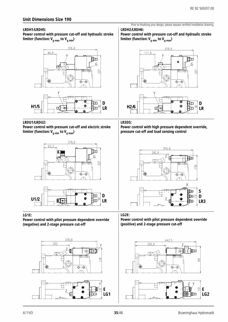
Unit Dimensions Size 190
LRDCS:Power control LR with pressure cut-off D, cross-sensing control C and load sensing control S
T1
R
XS
X
T2
M1
W
MZ G
B
S
Vg max
Y
BM
Z
G
LRCDS
Z
B(S)
S(A)
Vg min
T1
T2
T2
T1
Prior to finalising your design, please request certified installation drawing.
Ports
A, B Service port (without charging pump) SAE 1 1/2; 420 bar(6000 psi) High pressure series
S Suction port (without charging pump) SAE 3 1/2; 35 bar(500 psi) Standard series
T1, T2 Air bleed, tank M33x2; 16 deep
R Air bleed, oil drain M33x2; 16 deep
M1 Measuring point, regulating chamber M12x1,5; 12 deep
M Measuring point, service port M12x1,5; 12 deep
X Pilot port M14x1,5; 12 deepfor version with load sensing (S), DRL andremote pressure cut-off control (G)
Y Pilot port M14x1,5; 12 deepfor version with stroke limiter (H...),2-stage pressure cut-off (E) and HD
Z Pilot port M14x1,5; 12 deepor version with cross-sensing (C) andpower override (LR3, LG1)
G Port for positioning pressure (controller) M14x1,5; 12 deepfor version with stroke limiter (H.., U2),HD and EP with screwed fitting GE10 - PLM(otherwise port G closed)
Shaft endsZSplined shaft DIN 5480W50x2x30x24x9g
PCyl. shaft with keyDIN 6885 – AS16x10x100
TSplined shaft ANSI B92.1a-19762in 15T 8/16DP 1)(SAE J744 – 50-4 (F))
SSplined shaft ANSI B92.1a-19761 3/4in 13T 8/16DP 1)(SAE J744 – 44-4 (D))
View YClockwise rotation(Anti-clockwise rotation)
Detail W
M16; 24 deep
M16; 21 deep
Flange SAE J744165-4 (E)
1) 30° pressure angle, flat root, side fit, tolerance class 5
A11VO 35/48 Brueninghaus Hydromatik
RE 92 500/07.00
Unit Dimensions Size 190
LR3DS:Power control with high pressure dependent override,pressure cut-off and load sensing control
LG1E:Power control with pilot pressure dependent override(negative) and 2-stage pressure cut-off
LRDU1/LRDU2:Power control with pressure cut-off and electric strokelimiter (function: Vg min to Vg max)
LRDH1/LRDH5:Power control with pressure cut-off and hydraulic strokelimiter (function: Vg max to Vg min)
LRDH2/LRDH6:Power control with pressure cut-off and hydraulic strokelimiter (function: Vg min to Vg max)
LG2E:Power control with pilot pressure dependent override(positive) and 2-stage pressure cut-off
LG1E
Y
YZ
ZLG2E
YZ
Z
G
Y
Y
LRH1/5D
G
Y
Y
LRH2/6D
Z LR3DS
Z
X
LRU1/2D
G
Prior to finalising your design, please request certified installation drawing.

RE 92 500/07.00
Brueninghaus Hydromatik 36/48 A11VO
Unit Dimensions Size 190
DRL:Pressure control for parallel operation
EP1D/EP2D:Electric control (proportional solenoid) with pressure cut-off
HD1D/HD2D:Hydraulic, pilot pressure dependent control with pressurecut-off
LE1S/LE2S:Power control with electric override (negative) and loadsensing control
DR
X
EP1/2D
G
LE2
SX
HD1/2D
GY
Y
Prior to finalising your design, please request certified installation drawing.
X
DRS/G
DRS/DRG:Pressure control with load sensingPressure remote control

A11VO 37/48 Brueninghaus Hydromatik
RE 92 500/07.00
View YClockwise rotation(Anti-clockwise rotation)
Detail W
M16; 21 deep
M16; 21 deep
Unit Dimensions Size 190
Version with charging pump A11VLO190LRDS:Power control LR with pressure cut-off D and Load sensing control S
T1
T1
R
X S
X
T2
M1
M G
Vg max
Vg min
Y B(S)
B S(A)
S
BM G
DS
LR
W
T1
T2
T2
Prior to finalising your design, please request certified installation drawing.
PortsA, B Service port (with charging pump) SAE 1 1/2; 420 bar
(6000 psi) High pressure series
S Suction port (with charging pump) SAE 3 1/2; 35 bar(500 psi) Standard series
T1, T2 Air bleed, tank M33x2; 16 deep
R Air bleed, oil drain M33x2; 16 deep
M1 Measuring point, regulating chamber M12x1,5; 12 deep
M Measuring point, service port M12x1,5; 12 deep
X Pilot port M14x1,5; 12 deepfor version with load sensing (S), DRL andremote pressure cut-off control (G)
Y Pilot port M14x1,5; 12 deepfor version with stroke limiter (H...),2-stage pressure cut-off (E) and HD
Z Pilot port M14x1,5; 12 deepor version with cross-sensing (C) andpower override (LR3, LG1)
G Port for positioning pressure (controller) M14x1,5; 12 deepfor version with stroke limiter (H.., U2),HD and EP with screwed fitting GE10 - PLM(otherwise port G closed)
Flange SAE J744165-4 (E)

RE 92 500/07.00
Brueninghaus Hydromatik 38/48 A11VO
Unit Dimensions Size 260
LRDCS:Power control LR with pressure cut-off D, cross-sensing control C and load sensing control S
T1
T1
R
XS
X
T2
M1W
MZ G
B
S
Vg max
Y
BM
ZG
LRCDS
Z
B(S)
S(A)
Vg min
T1
T2
T2
Prior to finalising your design, please request certified installation drawing.
Ports
A, B Service port (without charging pump) SAE 1 1/2; 420 bar(6000 psi) High pressure series
S Suction port (without charging pump) SAE 3 1/2; 35 bar(500 psi) Standard series
T1, T2 Air bleed, tank M33x2; 16 deep
R Air bleed, oil drain M33x2; 16 deep
M1 Measuring point, regulating chamber M12x1,5; 12 deep
M Measuring point, service port M12x1,5; 12 deep
X Pilot port M14x1,5; 12 deepfor version with load sensing (S), DRL andremote pressure cut-off control (G)
Y Pilot port M14x1,5; 12 deepfor version with stroke limiter (H...),2-stage pressure cut-off (E) and HD
Z Pilot port M14x1,5; 12 deepor version with cross-sensing (C) andpower override (LR3, LG1)
G Port for positioning pressure (controller) M14x1,5; 12 deepfor version with stroke limiter (H.., U2),HD and EP with screwed fitting GE10 - PLM(otherwise port G closed)
Shaft endsZSplined shaft DIN 5480W60x2x30x28x9g
PCyl. shaft with keyDIN 6885 – AS18x11x100
TSplined shaft ANSI B92.1a-19762 1/4in 17T 8/16DP 1)
SSplined shaft ANSI B92.1a-19761 3/4in 13T 8/16DP 1)(SAE J744 – 44-4 (D))
View YClockwise rotation(Anti-clockwise rotation)
Detail W
M16; 21 deep
M16; 21 deep
Flange SAE J744165-4 (E)
1) 30° pressure angle, flat root, side fit, tolerance class 5

A11VO 39/48 Brueninghaus Hydromatik
RE 92 500/07.00
Unit Dimensions Size 260
LR3DS:Power control with high pressure dependent override,pressure cut-off and load sensing control
LG1E:Power control with pilot pressure dependent override(negative) and 2-stage pressure cut-off
LRDU1/LRDU2:Power control with pressure cut-off and electric strokelimiter (function: Vg min to Vg max)
LRDH1/LRDH5:Power control with pressure cut-off and hydraulic strokelimiter (function: Vg max to Vg min)
LRDH2/LRDH6:Power control with pressure cut-off and hydraulic strokelimiter (function: Vg min to Vg max)
LG2E:Power control with pilot pressure dependent override(positive) and 2-stage pressure cut-off
G
Y
Y
LRH2/6D
LRU1/2D
G
Z LR3DS
Z
X
LG2E
YZ
Z
G
Y
Y
LRH1/5D
LG1E
Y
YZ
Z
Prior to finalising your design, please request certified installation drawing.

RE 92 500/07.00
Brueninghaus Hydromatik 40/48 A11VO
Unit Dimensions Size 260
DRL:Pressure control for parallel operation
EP1D/EP2D:Electric control (proportional solenoid) with pressure cut-off
HD1D/HD2D:Hydraulic, pilot pressure dependent control with pressurecut-off
LE1S/LE2S:Power control with electric override (negative) and loadsensing control
LE2
SX
HD1/2D
GY
Y
EP1/2D
G
DR
X
Prior to finalising your design, please request certified installation drawing.
DRS/DRG:Pressure control with load sensingPressure remote control
X
DRS/G

A11VO 41/48 Brueninghaus Hydromatik
RE 92 500/07.00
Unit Dimensions Size 260
Version with charging pump A11VLO260LRDS:Power control LR with pressure cut-off D and Load sensing control S
T1
T1
R
X S
X
T2
M1
M G
Vg max
Vg min
Y B(S)
B S(A)
S
BM G
DS
LR
W
T1
T2
T2
Prior to finalising your design, please request certified installation drawing.
PortsA, B Service port (with charging pump) SAE 1 1/2; 420 bar
(6000 psi) High pressure series
S Suction port (with charging pump) SAE 4; 35 bar(500 psi) Standard series
T1, T2 Air bleed, tank M33x2; 16 deep
R Air bleed, oil drain M33x2; 16 deep
M1 Measuring point, regulating chamber M12x1,5; 12 deep
M Measuring point, service port M12x1,5; 12 deep
X Pilot port M14x1,5; 12 deepfor version with load sensing (S), DRL andremote pressure cut-off control (G)
Y Pilot port M14x1,5; 12 deepfor version with stroke limiter (H...),2-stage pressure cut-off (E) and HD
Z Pilot port M14x1,5; 12 deepor version with cross-sensing (C) andpower override (LR3, LG1)
G Port for positioning pressure (controller) M14x1,5; 12 deepfor version with stroke limiter (H.., U2),HD and EP with screwed fitting GE10 - PLM(otherwise port G closed)
View YClockwise rotation(Anti-clockwise rotation)
Detail W
M16; 21 deep
M16; 21 deep
Flange SAE J744165-4 (E)

RE 92 500/07.00
Brueninghaus Hydromatik 42/48 A11VO
Through Drive Dimensions
Ø 8
2,55
106,4130
146
Ø 1
01,6
45°
146
181
Ø 1
27
213
Overall length A1Size K07 K24 K80 K61
60 272 – 265 26575 290 – 283 28395 318 318 318 318
130 330 330 330 330130* 364 364 364 364190 367,8 367,8 367,8 367,8190* 400 400 400 400260 391,5 391,5 391,5 391,5260* 433,5 433,5 433,5 433,5
Overall length A1Size K01 K52
40 240 24060 257 25775 275 27595 306 306
130 339 339130* 373 373190 359,8 359,8190* 394 394260 385 385260* 427,3 427,3
Overall length A1Size K02 K04 K79
40 244 24460 261 261 26575 279 27995 303 303 303
130 326 326 326130* 360 360 360190 371,8 371,8 361,8190* 404 404 394260 395 395 395260* 437,5 437,5 437,5
*) Version with charging pump
Prior to finalising your design, please request certified installation drawing.
M10; 15 deep (sizes 60,75)M10; 12,5 deep (sizes 95-260)
*) Version with charging pump
*) Version with charging pump
M16; 15 deep (size 60-95)M16; 20 deep (size 130-260)
Flange SAE J744 – 127-2 (C) Hub for splined shaft to ANSI B92.1a-1976 1 1/4in 14T 12/24DP 1) (SAE J744 – 32-4 (C)) K071 1/2in 17T 12/24 DP 1) (SAE J744 – 38-4 (C-C)) K24
Hub for splined shaft to DIN 5480 W30x2x30x14x9g K80W35x2x30x16x9g K61
1) 30° pressure angle, flat root, side fit, tolerance class 5
Flange SAE J744 – 101-2 (B) Hub for splined shaft to ANSI B92.1a-1976 7/8in 13T 16/32DP 1) (SAE J744 – 22-4 (B)) K021in 15T 16/32DP 1) (SAE J744 – 25-4 (B-B)) K04
Hub for splined shaft to DIN 5480 W35x2x30x16x9g K79
Flange SAE J744 – 82-2 (A) Hub for splined shaft to ANSI B92.1a-1976 5/8in 9T 16/32DP 1) (SAE J744 – 16-4 (A)) K013/4in 11T 16/32DP 1) (SAE J744 – 19-4 (A-B)) K52
M12; 16 deep
A1to mounting flange
A1to mounting flange
A1to mounting flange
Note: The mounting flange can also be turned 90°. If required, please state in clear text.
Note: The mounting flange can also be turned 90°. If required, please state in clear text.
Note: The mounting flange can also be turned 90°. If required, please state in clear text.

A11VO 43/48 Brueninghaus Hydromatik
RE 92 500/07.00
Through Drive Dimensions
Ø 1
52,4
161,6 200
Ø 1
65,1
224,5
*) Version with charging pump
Overall length A1Size K72 K84 K67190 376,8 376,8 –190* 409 409 –260 417 400 400260* 459 442,5 442,5*)Version with charging pump
Overall length A1Size K86 K17 K81 K82 K83
75 290 – 290 – –95 317 – 317 317 –
130 340 350 340 340 340130* 374 384 374 374 374190 392 392 392 392 392190* 424 424 424 424 424260 417 417 417 417 417260* 459 459 459 459 459
Prior to finalising your design, please request certified installation drawing.
Flange SAE J744 – 152-4 (D) Hub for splined shaft to ANSI B92.1a-1976 1 1/4in 14T 12/24DP 1) (SAE J744 – 32-4 (C)) K861 3/4in 13T 8/16DP 1) (SAE J744 – 44-4 (D)) K17
Hub for splined shaft to DIN 5480 W40x2x30x18x9g K81W45x2x30x21x9g K82W50x2x30x24x9g K83
Flange SAE J744 – 165-4 (E) Hub for splined shaft to ANSI B92.1a-1976 1 3/4in 13T 8/16DP 1) (SAE J744 – 32-4 (C)) K72Hub for splined shaft to DIN 5480 W50x2x30x24x9g K84
W60x2x30x28x9g K67
1) 30° pressure angle, flat root, side fit, tolerance class 5
M12; 16 deep
M12; 16 deep
A1to mounting flange
A1to mounting flange

RE 92 500/07.00
Brueninghaus Hydromatik 44/48 A11VO
Overview of A11VO Attachments
Through drive – A11VO Attachment for 2nd pump Through drive
flange hub for Short A11VO A10V(S)O/31 A10V(S)O/52 A4FO A4VG A10VG external gear availablesplined shaft code size (shaft) size (shaft) size (shaft) size (shaft) size (shaft) size (shaft) pump for size
82-2 (A) 5/8in K01 — 18 (U) 10 (U) — — — G2 / 4-22 (R) 40...260
3/4in K52 — 18 (S) 10 (S) — — — — 40...260
101-2 (B) 7/8in K02 — 28 (S,R) 28 (S,R) 16 (S), 22 (S) — 18 (S) G3 / 20-45 (D) 40...26045 (U) 45 (U,W) 28 (S) G4 / 40-100 (D)
1in K04 40 (S) 45 (S,R) 45 (S,R) — 28 (S) 28 (S), 45 (S) — 40...26060 (U,W)
W35 K79 40 (Z) — — — — — — 40...260
127-2 (C) 1 1/4in K07 60 (S) 71 (S,R) 60 (S) — 40 (S), 56 (S) 63 (S) — 60...260100 (U) 85 (U) 71 (S)
1 1/2in K24 — 100 (S) 85 (S) — — — — 95...260
W30 K80 — — — — 40 (Z), 56 (Z) — — 60...260
W35 K61 60 (Z) — — — 40 (A), 56 (A) — — 60...26071 (Z)
152-4 (D) 1 1/4in K86 75 (S) — — — — — — 75...260
1 3/4in K17 95 (S), 130 (S) 140 (S) — — 90 (S), 125 (S) — — 130...260
W40 K81 75 (Z) — — — 125 (Z) — — 75...260
W45 K82 95 (Z) — — — 90 (A), 125 (A) — — 95...260
W50 K83 130 (Z) — — — — — — 130...260
165-4 (E) 1 3/4in K72 190 (S), 260 (S) — — — 180 (S), 250 (S) — — 190...260
W50 K84 190 (Z) — — — 180 (Z) — — 190...260
W60 K67 260 (Z) — — — — — — 260
Pump Combinations A11VO + A11VO
Overall length A1 1)A11VO A11VO (2nd pump)
(1st pump) size 40 size 60 size 75 size 95 size 130 size 130 2) size 190 size 190 2) size 260 size 260 2)
size 40 — — — — — — — — —
size 60 490 507 — — — — — — — —
size 75 525 550 — — — — — — —
size 95 528 560 577 604 — — — — — —
size130 551 572 600 627 650 698 — — — —
size1302) 585 606 634 661 684 732 — — — —
size190 586,8 609,8 652 679 702 750 723,6 772,3 — —
size1902) 619 642 684 711 734 782 755,8 804,5 — —
size260 620 633,5 677 704 727 775 746,8 795,5 772 828
size2602) 662,5 675,5 719 746 769 817 789,3 838 814,5 870,51) When using the Z shaft (splined shaft DIN 5480) for the mounted pump (2nd pump)2) Version with charging pump
Hub
Flange
A11VO(1st Pumpe)
A11VO(2nd Pumpe)
A
When ordering pump combinations the type designatins for the 1stand 2nd pumps should be joined by „+“
ordering code for 1st pump + ordering code for 2nd pump
Example order:
A11VO130LRDS/10R-NZD12K61 + A11VO60LRDS/10R-NZC12N00

A11VO 45/48 Brueninghaus Hydromatik
RE 92 500/07.00
Permissible Input or Through Drive Torque
Size 40 60 75 95 130 190 260
Torque at Vg max
and ∆p = 350 bar 1) Tmax Nm 234 324 412 522 723 1073 1447
Max permissible input torque 2)
at shaft end P TE zul. Nm 468 648 824 1044 1448 2226 2787
(key DIN 6885) (Ø32) (Ø35) (Ø40) (Ø45) (Ø50) (Ø55) (Ø60)
at shaft end Z TE zul. Nm 912 912 1460 2190 3140 3140 5780
(DIN 5480) (W35) (W35) (W40) (W45) (W50) (W50) (W60)
at shaft end S TE zul. Nm 314 602 602 1640 1640 1640 1640
(ANSI B92.1a-1976) (1in) (1 1/4in) (1 1/4in) (1 3/4in) (1 3/4in) (1 3/4in) (1 3/4in)
at shaft end T TE zul. Nm 602 970 970 — — 2670 4070
(ANSI B92.1a-1976) (1 1/4in) (1 3/8in) (1 3/8in) — — (2in) (2 1/4in)
Max perm. through drive torque 3) TD zul. Nm 314 521 660 822 1110 1760 20651) disregading efficiency2) for drive shafts not subject to radial stress3) Note max. perm. input torque for shaft S!
Key to symbols
TD zul. = Max. perm. through drive torque in Nm
TE zul. = Max. perm. input torquw at drive shaft in Nm
1,59 • Vg1 • ∆p1T1 = Torque decrease at 1st pump = in Nm
100 • ηmh
1,59 • Vg2 • ∆p2T2 = Torque decrease at 2nd pump = in Nm
100 • ηmh
Vg1 = Displacement per revolution, 1st pump in cm3
Vg2 = Displacement per revolution, 2nd pump in cm3
∆p1 = Differential pressure, 1st pump in bar
∆p2 = Differential pressure, 2nd pump in bar
ηmh = Mechanical-hydraulic efficiency
TETE
TD
T1
TD
T1
T2
2. Pumpe1. Pumpe
Torque distribution
Single pump Pump combination
1st pump 2nd pump

RE 92 500/07.00
Brueninghaus Hydromatik 46/48 A11VO
Swivel Angle Display
Optical swivel angle display (V)With the optical swivel angle display, the pump swivel position isshown by a mechanical indicator at the side of the housing.
Electric swivel angle display (R)With the electric swivel angle display, the pump swivel position isreported by a position sensor. This sensor converts the swivel positioninto an electrical signal.
Supply voltage: 5V
Output signal Uα: 2,5V ______________________ Vg min
4,5V ______________________ Vg max
The 6-pin AMP-MQS connector comprising:
– 6-pin MQS connector, code A ______________ 1-0967616-1
– 6 connector contacts ____________________ 0-0963727-2
– 6 single-conductor seals__________________ 0-0967067-1
– 3 blind plugs __________________________ 0-0967056-1
is not included in the supply.
Available from Brueninghaus Hydromatik on request.
Size A C40 50,5 84,060 not available75 60,7 97,095 63,5 104,0
130 70,9 112,0190 87,6 123,5260 87,6 137,0
Size A B C40 50,5 88,5 118,360 not available75 60,7 98,7 131,395 63,5 101,5 138,3
130 70,9 108,9 146,3190 87,6 125,6 157,8260 87,6 125,6 171,3
C
AB
A
C
Y
1 2 3
4 5 6
M A G
S M1
Vg max Vg min
R T1 T2
αU
Uα
M A G
S M1
Vg max Vg min
R T1 T2
Detail Y
M 2:1
Vg minVg max
Allocation:1: + (supply)2: – (earth)4: Uα

A11VO 47/48 Brueninghaus Hydromatik
RE 92 500/07.00
Installation and Commissioning Notes
Mounting below the tank
Pumping below minimum oil level in tank (standard).
➔ Installation position is optional.
➔ Installation position "shaft end upwards":
It is important to ensure that the pump housing is completely fullwhen commissioning. An air bubble in the bearing area will causedamage to the axial piston unit.
Steps:
➔ Before commissioning, fill axial piston pump via the highestleakage oil port T1, T2, R.
➔ Recommendation: fill the suction lines.
➔ Run pump at low speed (starter speed) until pump system iscompletely filled.
➔ Minimum immersion depth of suction or leakage oil line in tank:200 mm (in relation to min. oil level in tank).
GeneralThe pump housing must be filled with fluid during commissioningand remain full when operating (housing space filled).
Commissioning should be carried out at low speed and with no loaduntil all air has been bled from the system.
If the pump is idle for extended periods, the housing may drain viathe service lines. it is important to refill the housing sufficiently beforeputting it back into operation.
0,5
bar
*
T1S
T2 R
S
R
S
T1
T1
R
S
T
T2 R
S
T1 T2
S
T1T2
S
Leakage fluid in the housing space should be sent to the tank via thehighest leakage oil port. The minimum suction pressure at port S of0,8 bar abs. (without charging pump) or 0,6 bar (with charging pump)must be observed.
Mounting above the tank
Pumping above minimum oil level in tank.
➔ Installation position "shaft horizontal" and "shaft end upwards".
➔ Installation position "shaft end upwards":
If the pump is idle for extended periods, the housing space maydrain via the service lines (air enters via the shaft seal). The bearingsare thus insufficiently lubricated when the pump is started upagain. It is important to refill the axial piston pump via the highestleakage oil port before putting it back into operation (air bleedvia port R). A check valve in the leakage oil line (opening pressure0,5 bar) can prevent draining via the leakage oil line. Draining viathe service ports can be reduced via a special control plate design.
➔ Version A11VLO (with charging pump) is not designed formounting above the tank.
For steps, refer to mounting below the tank.
In addition please note the following:
➔ max. perm. suction height hmax = 800 mm
➔ min. perm. pressure at port S (min. suction pressure)
➔ when adjusting with pressure control, stroke limiter, HD and EPadjustment, set residual flow Vg ≥ 5% Vg max.
➔ Recommendation: use "swan neck" suction line.

RE 92 500/07.00
Not to be reproduced or copied – subject to technical change 48/48 A11VO
The data in this document is quoted solely forpurposes of product description and should notbe considered to constitute guaranteed andlegally binding properties.
Brueninghaus Hydromatik GmbH
Elchingen PlantGlockeraustraße 2 • D–89275 ElchingenTelefon +49 (0) 73 08 82-0Telefax +49 (0) 73 08 72 74
Internet: www.rexroth.com/brueninghaushydromatik / E-Mail: [email protected]
Preferred Types
Type ID numberA11VO40LRS/10R-NSC12N00 9609790A11VO40LRS/10R-NPC12N00 9609791A11VO40LRH2/10R-NSC12N00 9609792A11VO40LRH2/10R-NPC12N00 9609793A11VO40DRS/10R-NSC12N00 9609656A11VO40DRS/10R-NPC12N00 9609794
A11VO60LRS/10R-NSC12N00 9609798A11VO60LRS/10R-NPC12N00 9609799A11VO60LRS/10R-NSC12K01 9609800A11VO60LRS/10R-NPC12K01 9609801A11VO60LRH2/10R-NSC12N00 9609802A11VO60LRH2/10R-NPC12N00 9609803A11VO60LRH2/10R-NSC12K01 9609804A11VO60LRH2/10R-NPC12K01 9609805A11VO60DRS/10R-NSC12N00 9606644A11VO60DRS/10R-NPC12N00 9609807A11VO60DRS/10R-NSC12K01 9601648A11VO60DRS/10R-NPC12K01 9609809
A11VO75LRS/10R-NSD12N00 9609815A11VO75LRS/10R-NPD12N00 9609816A11VO75LRS/10R-NSD12K01 9609817A11VO75LRS/10R-NPD12K01 9609818A11VO75LRH2/10R-NSD12N00 9609819A11VO75LRH2/10R-NPD12N00 9608474A11VO75LRH2/10R-NSD12K01 9609821A11VO75LRH2/10R-NPD12K01 9609822A11VO75DRS/10R-NSD12N00 9448021A11VO75DRS/10R-NPD12N00 9609824A11VO75DRS/10R-NSD12K01 9609825A11VO75DRS/10R-NPD12K01 9609826
A11VO95LRS/10R-NSD12N00 9609834A11VO95LRS/10R-NPD12N00 9609835A11VO95LRS/10R-NSD12K01 9609836A11VO95LRS/10R-NPD12K01 9609837A11VO95LRH2/10R-NSD12N00 9609838A11VO95LRH2/10R-NPD12N00 9609839A11VO95LRH2/10R-NSD12K01 9609840A11VO95LRH2/10R-NPD12K01 9609841A11VO95DRS/10R-NSD12N00 9609842A11VO95DRS/10R-NPD12N00 9608484A11VO95DRS/10R-NSD12K01 9609844A11VO95DRS/10R-NPD12K01 9609845
Type ID numberA11VO130LRS/10R-NSD12N00 9609848A11VO130LRS/10R-NPD12N00 9609646A11VO130LRS/10R-NSD12K02 9609850A11VO130LRS/10R-NPD12K02 9609851A11VO130LRH2/10R-NSD12N00 9609852A11VO130LRH2/10R-NPD12N00 9609853A11VO130LRH2/10R-NSD12K02 9609854A11VO130LRH2/10R-NPD12K02 9609855A11VO130DRS/10R-NSD12N00 2005582A11VO130DRS/10R-NPD12N00 9609857A11VO130DRS/10R-NSD12K02 9609858A11VO130DRS/10R-NPD12K02 9609859
A11VLO190LRS/11R-NSD12N00 2015194A11VLO190LRS/11R-NPD12N00 2015195A11VLO190LRS/11R-NSD12K02 2015196A11VLO190LRS/11R-NPD12K02 2015197A11VLO190HD1/11R-NSD12N00 2048497A11VLO190HD1/11R-NPD12N00 2048499A11VLO190HD1/11R-NSD12K02 2048501A11VLO190HD1/11R-NPD12K02 2048503A11VLO190HD2/11R-NSD12N00 2048498A11VLO190HD2/11R-NPD12N00 2048500A11VLO190HD2/11R-NSD12K02 2048502A11VLO190HD2/11R-NPD12K02 2048504A11VLO190EP2/11R-NSD12N00 2048505A11VLO190EP2/11R-NPD12N00 2048506A11VLO190EP2/11R-NSD12K02 2048507A11VLO190EP2/11R-NPD12K02 2048508
A11VLO260LRS/11R-NSD12N00 2015256A11VLO260LRS/11R-NPD12N00 2015257A11VLO260LRS/11R-NSD12K02 2015258A11VLO260LRS/11R-NPD12K02 2015259A11VLO260HD1/11R-NSD12N00 2048509A11VLO260HD1/11R-NPD12N00 2048511A11VLO260HD1/11R-NSD12K02 2048513A11VLO260HD1/11R-NPD12K02 2048515A11VLO260HD2/11R-NSD12N00 2048510A11VLO260HD2/11R-NPD12N00 2048512A11VLO260HD2/11R-NSD12K02 2048514A11VLO260HD2/11R-NPD12K02 2048516A11VLO260EP2/11R-NSD12N00 2048517A11VLO260EP2/11R-NPD12N00 2048518A11VLO260EP2/11R-NSD12K02 2048519A11VLO260EP2/11R-NPD12K02 2048520
When ordering, please quote type and ID number