Rexroth IndraDrive Mi Drive Systems · Rexroth IndraDrive Mi Drive Systems R911320924 Edition 01...
138
Rexroth IndraDrive Mi Drive Systems R911320924 Edition 01 Electric Drives and Controls Pneumatics Service Linear Motion and Assembly Technologies Hydraulics
Transcript of Rexroth IndraDrive Mi Drive Systems · Rexroth IndraDrive Mi Drive Systems R911320924 Edition 01...
Rexroth IndraDrive MiDrive Systems
R911320924Edition 01
Project Planning Manual
Electric Drivesand Controls Pneumatics Service
Linear Motion and Assembly TechnologiesHydraulics
About this Documentation
DOK-INDRV*-KCU+KSM****-PR01-EN-P
Rexroth IndraDrive MiDrive Systems
Project Planning Manual
DOK-INDRV*-KCU+KSM****-PR01-EN-P
120-2400-B324-01/EN
This documentation describes …• how to design the control cabinet• how to install the drive system
Description Release Date NotesDOK-INDRV*-KCU+KSM****-PR01-EN-P 2007-04 First edition
Bosch Rexroth AG 2007Copying this document, giving it to others and the use or communicationof the contents thereof without express authority, are forbidden. Offendersare liable for the payment of damages. All rights are reserved in the eventof the grant of a patent or the registration of a utility model or design(DIN 34-1).
The data specified above only serve to describe the product. Nostatements concerning a certain condition or suitability for a certainapplication can be derived from our information. The given informationdoes not release the user from the obligation of own judgement andverification. It must be remembered that our products are subject to anatural process of wear and aging.
Bosch Rexroth AGBgm.-Dr.-Nebel-Str. 2 • D-97816 Lohr a. MainTelephone +49 (0)93 52/40-0 • Tx 68 94 21 • Fax +49 (0)93 52/40-48 85http://www.boschrexroth.de/Dept. BRC/EDY1 (MW/RR/US/BB) and BRC/EDM2 (JW)
This document has been printed on chlorine-free bleached paper.
Title
Type of Documentation
Document Typecode
Internal File Reference
Purpose of Documentation
Record of Revisions
Copyright
Validity
Published by
Note
Rexroth IndraDrive Mi Contents I
DOK-INDRV*-KCU+KSM****-PR01-EN-P
Contents
1 System Presentation 1-11.1 Introduction ................................................................................................................................... 1-1
Rexroth IndraDrive Mi.............................................................................................................. 1-1Features................................................................................................................................... 1-1
1.2 Drive System Rexroth IndraDrive Mi ............................................................................................ 1-2Components ............................................................................................................................ 1-2System Structure ..................................................................................................................... 1-3Overview of Functions ............................................................................................................. 1-5
1.3 Type Code .................................................................................................................................... 1-5Introduction .............................................................................................................................. 1-5Distributed Servo Drive KSM................................................................................................... 1-6Electronic Control System KCU............................................................................................... 1-9Firmware.................................................................................................................................. 1-9
1.4 Guide to the Documentation ....................................................................................................... 1-10Documentation Structure....................................................................................................... 1-10Documentations - Overview .................................................................................................. 1-10
2 Important Directions for Use 2-12.1 Appropriate Use............................................................................................................................ 2-1
Introduction .............................................................................................................................. 2-1Areas of Use and Application .................................................................................................. 2-1
2.2 Inappropriate Use ......................................................................................................................... 2-2
3 Safety Instructions for Electric Drives and Controls 3-13.1 General Information ...................................................................................................................... 3-1
Using the Safety Instructions and Passing Them on to Others............................................... 3-1Instructions for Use.................................................................................................................. 3-1Explanation of Warning Symbols and Degrees of Hazard Seriousness ................................. 3-3Hazards by Improper Use........................................................................................................ 3-3
3.2 Instructions with Regard to Specific Dangers............................................................................... 3-5Protection Against Contact with Electrical Parts ..................................................................... 3-5Protection Against Electric Shock by Protective Extra-Low Voltage (PELV) .......................... 3-7Protection Against Dangerous Movements ............................................................................. 3-7Protection Against Magnetic and Electromagnetic Fields During Operation andMounting .................................................................................................................................. 3-9Protection Against Contact with Hot Parts ............................................................................ 3-10Protection During Handling and Mounting............................................................................. 3-11Battery Safety ........................................................................................................................ 3-11Protection Against Pressurized Systems .............................................................................. 3-12
II Contents Rexroth IndraDrive Mi
DOK-INDRV*-KCU+KSM****-PR01-EN-P
4 General Specification of the Components 4-14.1 Certifications ................................................................................................................................. 4-14.2 Transport and Storage.................................................................................................................. 4-2
Transporting the Devices......................................................................................................... 4-2Storing the Devices ................................................................................................................. 4-2
4.3 Installation Conditions................................................................................................................... 4-2Ambient and Operating Conditions.......................................................................................... 4-2Type of Construction and Mounting Positions......................................................................... 4-4Compatibility with Foreign Matters .......................................................................................... 4-4Prime Coat and Housing Varnish ............................................................................................ 4-4
4.4 Capacity Utilization ....................................................................................................................... 4-5
5 Technical Data of the Components 5-15.1 Explanation of Terms and Definitions........................................................................................... 5-15.2 Distributed Servo Drive KSM........................................................................................................ 5-5
KSM Data Sheet ...................................................................................................................... 5-5KSM Characteristics ................................................................................................................ 5-7Dimensions and Technical Design ........................................................................................ 5-10Bearings and Shaft Load ....................................................................................................... 5-12
5.3 Electronic Control System KCU.................................................................................................. 5-14Brief Description and Applications......................................................................................... 5-14Technical Data....................................................................................................................... 5-14
5.4 Hybrid Cables RKH..................................................................................................................... 5-17Technical Data....................................................................................................................... 5-17Selecting Ready-Made Cables .............................................................................................. 5-17Interconnection Diagrams for Ready-Made Hybrid Cables................................................... 5-19
6 Connection Points 6-16.1 Connection Points of System ....................................................................................................... 6-1
Equipment Grounding Conductor ............................................................................................ 6-1Ground Connection ................................................................................................................. 6-2
6.2 Connection Points of KCU............................................................................................................ 6-3Positions of the Connection Points.......................................................................................... 6-3X1, Module Bus ....................................................................................................................... 6-4X20 TX, X21 RX (SERCOS interface)..................................................................................... 6-5X50, E-Stop Input .................................................................................................................... 6-6X51, Master Communication SERCOS................................................................................... 6-6X52, Status Messages............................................................................................................. 6-7X53, Control Voltage Output.................................................................................................... 6-7X54, DC Bus, Equipment Grounding Conductor Output KSM ................................................ 6-8DC Bus Connection L+, L-....................................................................................................... 6-9Control Voltage Supply +24V, 0V.......................................................................................... 6-11Connection Accessory........................................................................................................... 6-12
6.3 Connection Points of KSM.......................................................................................................... 6-13Positions of the Connection Points........................................................................................ 6-13X2 Serial Interface, Service Input "Release Brake"............................................................... 6-14

Rexroth IndraDrive Mi Contents III
DOK-INDRV*-KCU+KSM****-PR01-EN-P
X3.1, X3.2 Connection Point Hybrid Cable ........................................................................... 6-15X7 Connection Point MultiMediaCard (MMC) ....................................................................... 6-16X37, X38 Digital Inputs/Outputs ............................................................................................ 6-17Ground Connection ............................................................................................................... 6-20
7 Notes on Project Planning 7-17.1 Notes on Mechanical Project Planning......................................................................................... 7-1
Mounting Clearance ................................................................................................................ 7-1Output Shaft............................................................................................................................. 7-1Bearings and Shaft Load ......................................................................................................... 7-3Holding Brakes ........................................................................................................................ 7-5Mechanical Attachment of Driving Elements........................................................................... 7-8
7.2 Notes on Electrical Project Planning .......................................................................................... 7-10Allowed Cable Lengths.......................................................................................................... 7-10Maximum Number of Axes per System Combination............................................................ 7-1024V Control Voltage .............................................................................................................. 7-11Power Supply......................................................................................................................... 7-13Electronic Control System KCU............................................................................................. 7-13Address Selector Switch........................................................................................................ 7-14Motor Blower.......................................................................................................................... 7-15Motor Current Limitation ........................................................................................................ 7-15Motor Temperature................................................................................................................ 7-16Switching Frequency ............................................................................................................. 7-16
8 Identification 8-18.1 Scope of Supply............................................................................................................................ 8-1
KSM ......................................................................................................................................... 8-1KCU ......................................................................................................................................... 8-1
8.2 Identifying and Checking the Delivered Components .................................................................. 8-1Type Plate KSM....................................................................................................................... 8-1Type Plate KCU....................................................................................................................... 8-3
9 Mounting and Installation 9-19.1 Introduction ................................................................................................................................... 9-1
Important Notes ....................................................................................................................... 9-1System Overview..................................................................................................................... 9-1Connection Diagram KCU ....................................................................................................... 9-3
9.2 Mounting ....................................................................................................................................... 9-4Practical Tips ........................................................................................................................... 9-4Required Steps to Follow ........................................................................................................ 9-4Mechanical Interfaces.............................................................................................................. 9-5
9.3 Electrical Connection .................................................................................................................... 9-6Notes ....................................................................................................................................... 9-7Electrical Interfaces ................................................................................................................. 9-7
9.4 Handling of the Devices.............................................................................................................. 9-10
IV Contents Rexroth IndraDrive Mi
DOK-INDRV*-KCU+KSM****-PR01-EN-P
10 Commissioning, Operation, Diagnoses, Service and Maintenance 10-110.1 Notes on Commissioning............................................................................................................ 10-1
Preparing ............................................................................................................................... 10-1Carrying Out .......................................................................................................................... 10-1
10.2 Notes on Operation..................................................................................................................... 10-110.3 Diagnostic Functions .................................................................................................................. 10-2
Distributed Servo Drive KSM................................................................................................. 10-2Electronic Control System KCU............................................................................................. 10-3Diagnostic Messages via Parameters ................................................................................... 10-4Firmware Functions ............................................................................................................... 10-4
10.4 Service Functions/Troubleshooting ............................................................................................ 10-5Deactivating and Dismounting the Drive ............................................................................... 10-5Replacing KSM...................................................................................................................... 10-6Service Function "Release Holding Brake" ........................................................................... 10-7Saving Parameters ................................................................................................................ 10-7Firmware Update ................................................................................................................... 10-7MMC ...................................................................................................................................... 10-8
10.5 Maintenance ............................................................................................................................... 10-8Maintenance of the Motor Component .................................................................................. 10-8Maintenance of the Electronic System of the Drive............................................................. 10-10
11 Disposal and Environmental Protection 11-111.1 Disposal ...................................................................................................................................... 11-1
Products................................................................................................................................. 11-1Packaging Materials .............................................................................................................. 11-1
11.2 Environmental Protection............................................................................................................ 11-1No Release of Hazardous Substances ................................................................................. 11-1Materials Contained in the Products ..................................................................................... 11-1Recycling ............................................................................................................................... 11-2
12 Appendix 12-112.1 Discharging of DC Bus Capacitors ............................................................................................. 12-112.2 Discharging Device..................................................................................................................... 12-2
13 Service and Support 13-113.1 Helpdesk..................................................................................................................................... 13-113.2 Service Hotline............................................................................................................................ 13-113.3 Internet........................................................................................................................................ 13-113.4 Helpful Information...................................................................................................................... 13-1
14 Index 14-1
Rexroth IndraDrive Mi System Presentation 1-1
DOK-INDRV*-KCU+KSM****-PR01-EN-P
1 System Presentation
1.1 Introduction
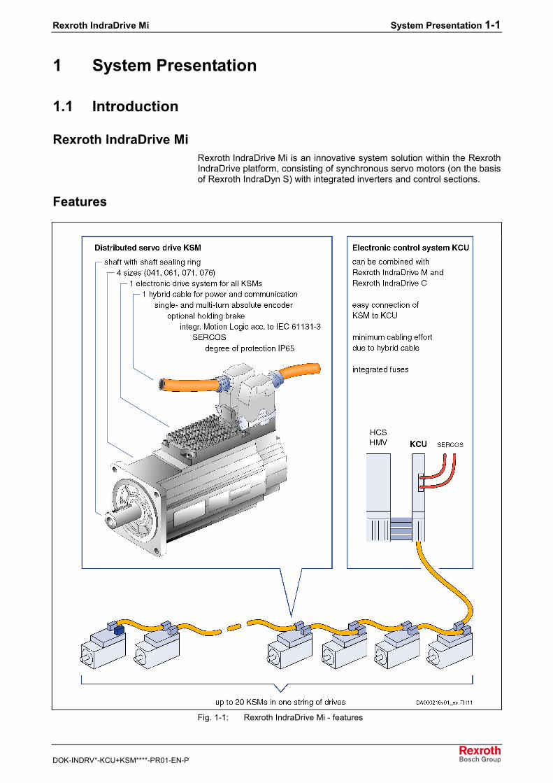
Rexroth IndraDrive MiRexroth IndraDrive Mi is an innovative system solution within the RexrothIndraDrive platform, consisting of synchronous servo motors (on the basisof Rexroth IndraDyn S) with integrated inverters and control sections.
Features
Fig. 1-1: Rexroth IndraDrive Mi - features
1-2 System Presentation Rexroth IndraDrive Mi
DOK-INDRV*-KCU+KSM****-PR01-EN-P
In the following points, the system solution Rexroth IndraDrive Mi differsfrom a standard solution with Rexroth IndraDrive and Rexroth IndraDyn:• limited performance levels and exclusively available on the basis of
Rexroth IndraDyn S, i.e. no linear and kit motors• SERCOS interface as master communication
1.2 Drive System Rexroth IndraDrive Mi
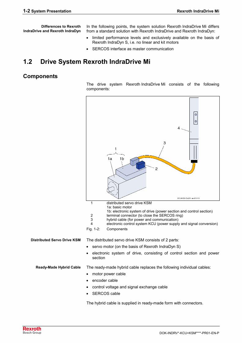
ComponentsThe drive system Rexroth IndraDrive Mi consists of the followingcomponents:
1 distributed servo drive KSM1a: basic motor1b: electronic system of drive (power section and control section)
2 terminal connector (to close the SERCOS ring)3 hybrid cable (for power and communication)4 electronic control system KCU (power supply and signal conversion)
Fig. 1-2: Components
The distributed servo drive KSM consists of 2 parts:• servo motor (on the basis of Rexroth IndraDyn S)• electronic system of drive, consisting of control section and power
section
The ready-made hybrid cable replaces the following individual cables:• motor power cable• encoder cable• control voltage and signal exchange cable• SERCOS cable
The hybrid cable is supplied in ready-made form with connectors.
Differences to RexrothIndraDrive and Rexroth IndraDyn
Distributed Servo Drive KSM
Ready-Made Hybrid Cable
Rexroth IndraDrive Mi System Presentation 1-3
DOK-INDRV*-KCU+KSM****-PR01-EN-P
The electronic control system KCU• supplies power to the distributed servo drives (from the DC bus
connection to an HMV supply unit or HCS converter)• with integrated fuses protects the hybrid cable against electric
overload• allows communication between the higher-level control unit and the
distributed servo drives
LinesSee chapter "Type Code"• distributed servo drive KSM• electronic control system KCU
System StructureThe supply unit which is used significantly defines the system structure.Possible supply units:• Rexroth IndraDrive supply unit HMV01.1E/R or HMV02.1R• Rexroth IndraDrive converter HCS02.1 or HCS03.1 (makes sense if
another axis is required)
The figure below illustrates the system structure with all involvedcomponents (with HMV as supply unit).
Electronic Control System KCU

1-4 System Presentation Rexroth IndraDrive Mi
DOK-INDRV*-KCU+KSM****-PR01-EN-P
DST transformer (optional)F fusesHMD, HMS inverterHMV supply unitHNF mains filterHNL mains chokeKCU electronic control systemKSM distributed servo driveMSK servo motor24V 24V supply1 mains contactor (for supply units without integrated mains
contactor, e.g. HMV01.2R-W0120)2 terminal connectorX3.2 connection of hybrid cable
Fig. 1-3: System structure
Rexroth IndraDrive Mi System Presentation 1-5
DOK-INDRV*-KCU+KSM****-PR01-EN-P
Overview of Functions
Firmware Functions (Functional Packages)
Note: For details on the available firmware functions, see chapter"Functional Packages" of the Functional Description forfirmware MPB04VRS or higher.
Hardware-related functional restrictions as compared to drive controllerswith CSB and CSH control sections:• no safety technology• no analog inputs or outputs• no digital and analog I/O extensions
1.3 Type Code
IntroductionThe type code is the basis of each purchase order of a Rexroth product.
It unequivocally describes all variants which can be supplied.• distributed servo drive KSM• electronic control system KCU• firmware ≥ MPB04V20
For product selection and purchase order, take the following aspects intoaccount:• Detailed information and instructions in the chapters "Technical Data"
and "Notes on Project Planning"• Before placing a purchase order, have our sales representative check
whether individual options are available
Note: The following figures illustrate the basic structure of the typecodes. Our sales representative will help you with the currentstatus of available versions.
Notes on Product Selection
1-6 System Presentation Rexroth IndraDrive Mi
DOK-INDRV*-KCU+KSM****-PR01-EN-P
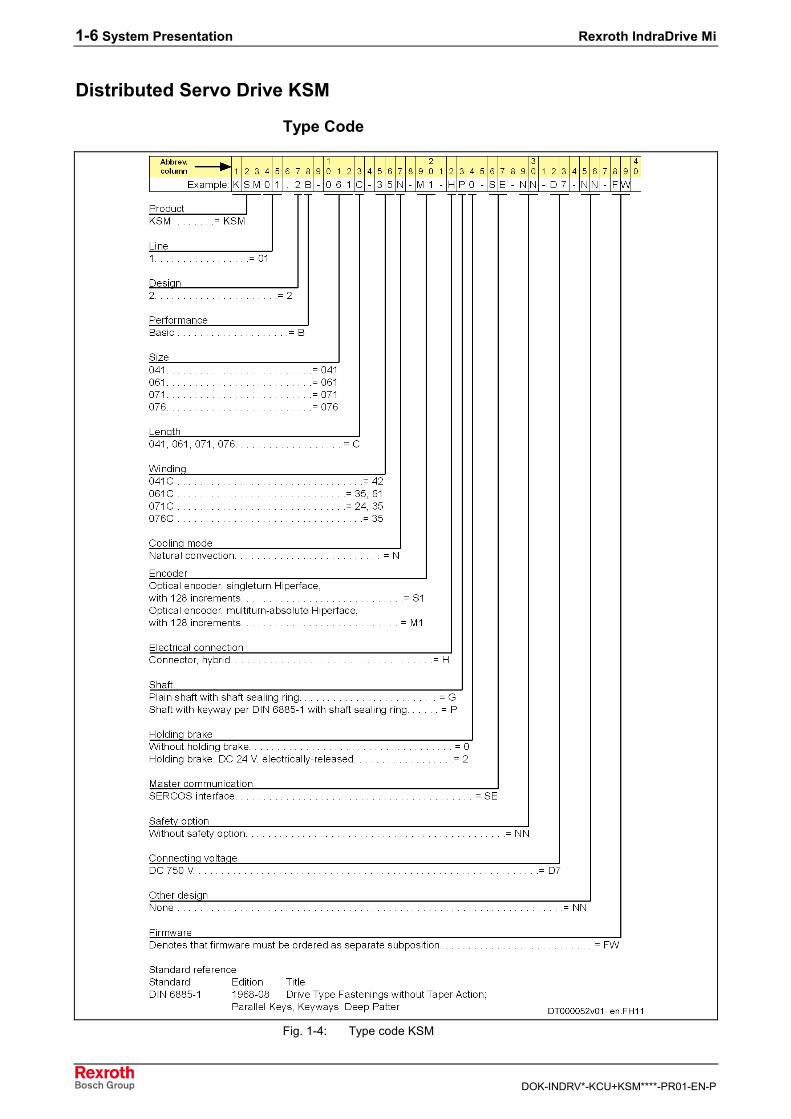
Distributed Servo Drive KSM
Type Code
Fig. 1-4: Type code KSM
Rexroth IndraDrive Mi System Presentation 1-7
DOK-INDRV*-KCU+KSM****-PR01-EN-P
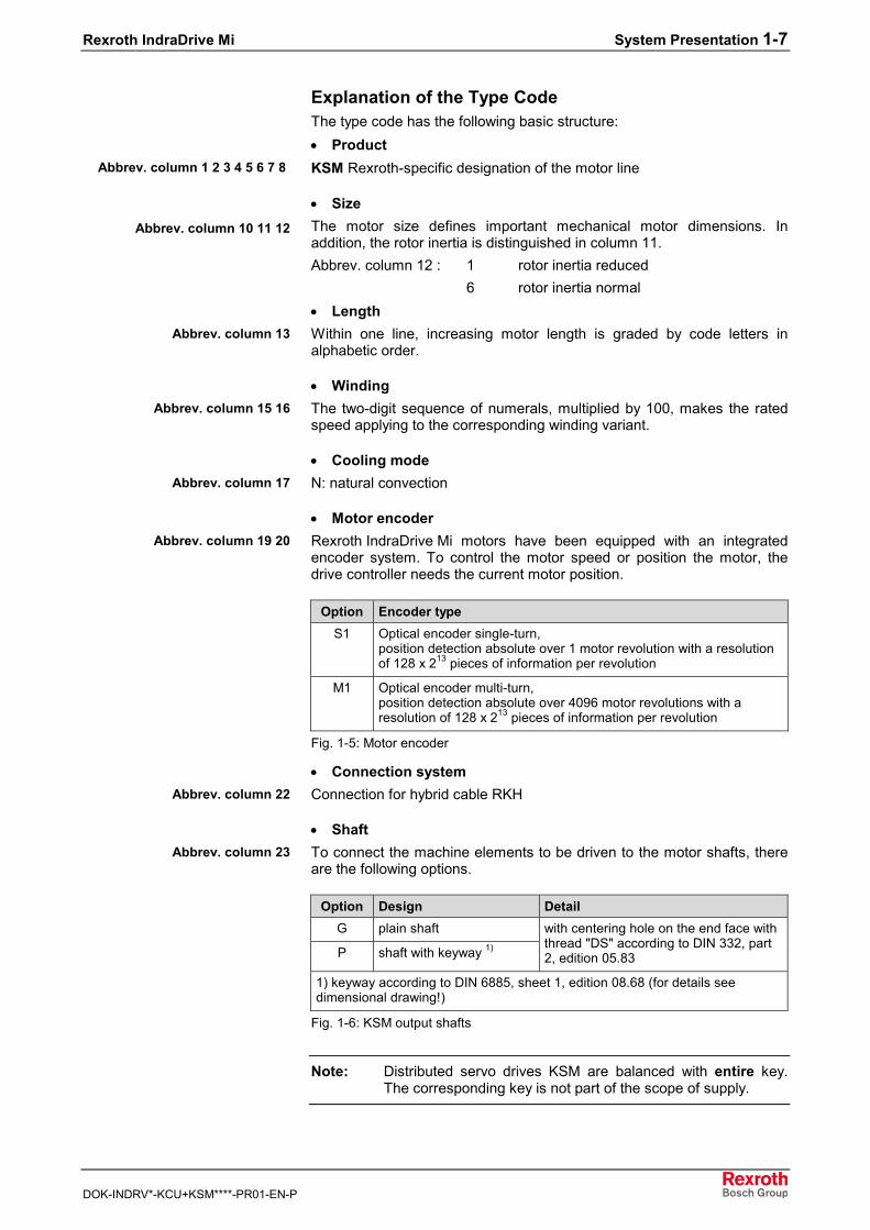
Explanation of the Type CodeThe type code has the following basic structure:• ProductKSM Rexroth-specific designation of the motor line
• SizeThe motor size defines important mechanical motor dimensions. Inaddition, the rotor inertia is distinguished in column 11.Abbrev. column 12 : 1 rotor inertia reduced
6 rotor inertia normal• LengthWithin one line, increasing motor length is graded by code letters inalphabetic order.
• WindingThe two-digit sequence of numerals, multiplied by 100, makes the ratedspeed applying to the corresponding winding variant.
• Cooling modeN: natural convection
• Motor encoderRexroth IndraDrive Mi motors have been equipped with an integratedencoder system. To control the motor speed or position the motor, thedrive controller needs the current motor position.
Option Encoder typeS1 Optical encoder single-turn,
position detection absolute over 1 motor revolution with a resolutionof 128 x 213 pieces of information per revolution
M1 Optical encoder multi-turn,position detection absolute over 4096 motor revolutions with aresolution of 128 x 213 pieces of information per revolution
Fig. 1-5: Motor encoder
• Connection systemConnection for hybrid cable RKH
• ShaftTo connect the machine elements to be driven to the motor shafts, thereare the following options.
Option Design DetailG plain shaft
P shaft with keyway 1)
with centering hole on the end face withthread "DS" according to DIN 332, part2, edition 05.83
1) keyway according to DIN 6885, sheet 1, edition 08.68 (for details seedimensional drawing!)
Fig. 1-6: KSM output shafts
Note: Distributed servo drives KSM are balanced with entire key.The corresponding key is not part of the scope of supply.
Abbrev. column 1 2 3 4 5 6 7 8
Abbrev. column 10 11 12
Abbrev. column 13
Abbrev. column 15 16
Abbrev. column 17
Abbrev. column 19 20
Abbrev. column 22
Abbrev. column 23
1-8 System Presentation Rexroth IndraDrive Mi
DOK-INDRV*-KCU+KSM****-PR01-EN-P
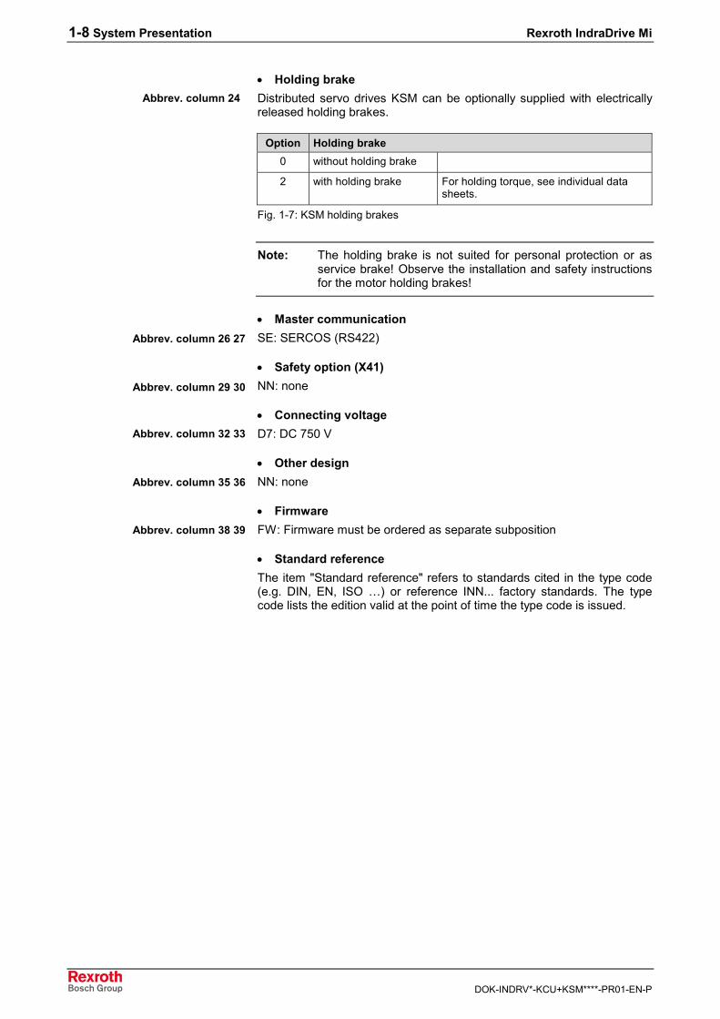
• Holding brakeDistributed servo drives KSM can be optionally supplied with electricallyreleased holding brakes.
Option Holding brake0 without holding brake
2 with holding brake For holding torque, see individual datasheets.
Fig. 1-7: KSM holding brakes
Note: The holding brake is not suited for personal protection or asservice brake! Observe the installation and safety instructionsfor the motor holding brakes!
• Master communicationSE: SERCOS (RS422)
• Safety option (X41)NN: none
• Connecting voltageD7: DC 750 V
• Other designNN: none
• FirmwareFW: Firmware must be ordered as separate subposition
• Standard referenceThe item "Standard reference" refers to standards cited in the type code(e.g. DIN, EN, ISO …) or reference INN... factory standards. The typecode lists the edition valid at the point of time the type code is issued.
Abbrev. column 24
Abbrev. column 26 27
Abbrev. column 29 30
Abbrev. column 32 33
Abbrev. column 35 36
Abbrev. column 38 39
Rexroth IndraDrive Mi System Presentation 1-9
DOK-INDRV*-KCU+KSM****-PR01-EN-P
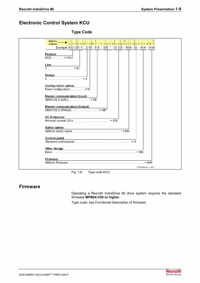
Electronic Control System KCU
Type Code
Fig. 1-8: Type code KCU
FirmwareOperating a Rexroth IndraDrive Mi drive system requires the standardfirmware MPB04-V20 or higher.Type code: see Functional Description of firmware
1-10 System Presentation Rexroth IndraDrive Mi
DOK-INDRV*-KCU+KSM****-PR01-EN-P
1.4 Guide to the Documentation
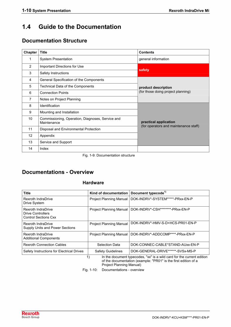
Documentation Structure
Chapter Title Contents
1 System Presentation general information
2 Important Directions for Use
3 Safety Instructionssafety
4 General Specification of the Components
5 Technical Data of the Components
6 Connection Points
7 Notes on Project Planning
product description(for those doing project planning)
8 Identification
9 Mounting and Installation
10 Commissioning, Operation, Diagnoses, Service andMaintenance
11 Disposal and Environmental Protection
12 Appendix
13 Service and Support
practical application(for operators and maintenance staff)
14 Index
Fig. 1-9: Documentation structure
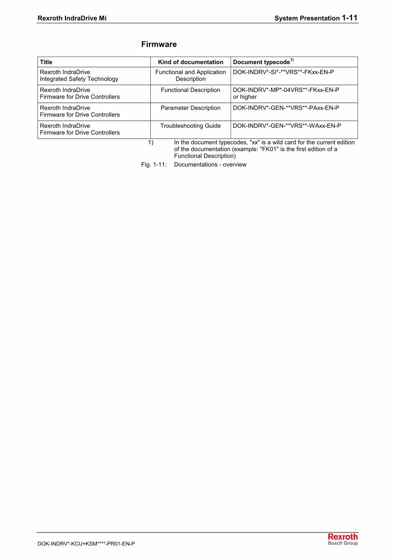
Documentations - Overview
Hardware
Title Kind of documentation Document typecode1)
Rexroth IndraDriveDrive System
Project Planning Manual DOK-INDRV*-SYSTEM*****-PRxx-EN-P
Rexroth IndraDriveDrive ControllersControl Sections Cxx
Project Planning Manual DOK-INDRV*-CSH********-PRxx-EN-P
Rexroth IndraDriveSupply Units and Power Sections
Project Planning Manual DOK-INDRV*-HMV-S-D+HCS-PR01-EN-P
Rexroth IndraDriveAdditional Components
Project Planning Manual DOK-INDRV*-ADDCOMP****-PRxx-EN-P
Rexroth Connection Cables Selection Data DOK-CONNEC-CABLE*STAND-AUxx-EN-P
Safety Instructions for Electrical Drives Safety Guidelines DOK-GENERAL-DRIVE******-SVSx-MS-P1) In the document typecodes, "xx" is a wild card for the current edition
of the documentation (example: "PR01" is the first edition of aProject Planning Manual)
Fig. 1-10: Documentations - overview
Rexroth IndraDrive Mi System Presentation 1-11
DOK-INDRV*-KCU+KSM****-PR01-EN-P
Firmware
Title Kind of documentation Document typecode1)
Rexroth IndraDriveIntegrated Safety Technology
Functional and ApplicationDescription
DOK-INDRV*-SI*-**VRS**-FKxx-EN-P
Rexroth IndraDriveFirmware for Drive Controllers
Functional Description DOK-INDRV*-MP*-04VRS**-FKxx-EN-Por higher
Rexroth IndraDriveFirmware for Drive Controllers
Parameter Description DOK-INDRV*-GEN-**VRS**-PAxx-EN-P
Rexroth IndraDriveFirmware for Drive Controllers
Troubleshooting Guide DOK-INDRV*-GEN-**VRS**-WAxx-EN-P
1) In the document typecodes, "xx" is a wild card for the current editionof the documentation (example: "FK01" is the first edition of aFunctional Description)
Fig. 1-11: Documentations - overview

1-12 System Presentation Rexroth IndraDrive Mi
DOK-INDRV*-KCU+KSM****-PR01-EN-P
Rexroth IndraDrive Mi Important Directions for Use 2-1
DOK-INDRV*-KCU+KSM****-PR01-EN-P
2 Important Directions for Use
2.1 Appropriate Use
IntroductionRexroth products represent state-of-the-art developments andmanufacturing. They are tested prior to delivery to ensure operating safetyand reliability.The products may only be used in the manner that is defined asappropriate. If they are used in an inappropriate manner, then situationscan develop that may lead to property damage or injury to personnel.
Note: Rexroth as manufacturer is not liable for any damagesresulting from inappropriate use. In such cases, the guaranteeand the right to payment of damages resulting frominappropriate use are forfeited. The user alone carries allresponsibility of the risks.
Before using Rexroth products, make sure that all the pre-requisites foran appropriate use of the products are satisfied:• Personnel that in any way, shape or form uses our products must first
read and understand the relevant safety instructions and be familiarwith appropriate use.
• If the products take the form of hardware, then they must remain intheir original state, in other words, no structural changes are permitted.It is not permitted to decompile software products or alter sourcecodes.
• Do not mount damaged or faulty products or use them in operation.• Make sure that the products have been installed in the manner
described in the relevant documentation.
Areas of Use and ApplicationDrive controllers made by Rexroth are designed to control electricalmotors and monitor their operation.Control and monitoring of the motors may require additional sensors andactors.
Note: The drive controllers may only be used with the accessoriesand parts specified in this document. If a component has notbeen specifically named, then it may neither be mounted norconnected. The same applies to cables and lines.Operation is only permitted in the specified configurations andcombinations of components using the software and firmwareas specified in the relevant Functional Descriptions.
Every drive controller has to be programmed before commissioning,making it possible for the motor to execute the specific functions of anapplication.The drive controllers have been developed for use in single- and multi-axis drive and control tasks.To ensure application-specific use, the drive controllers are available withdifferent drive power and different interfaces.
2-2 Important Directions for Use Rexroth IndraDrive Mi
DOK-INDRV*-KCU+KSM****-PR01-EN-P
Typical applications of the drive controllers include:• handling and mounting systems,• packaging and food machines,• printing and paper processing machines and• machine tools.The drive controllers may only be operated under the assembly andinstallation conditions described in this documentation, in the specifiedposition of normal use and under the ambient conditions as described(temperature, degree of protection, humidity, EMC, etc.).
2.2 Inappropriate UseUsing the drive controllers outside of the operating conditions described inthis documentation and outside of the indicated technical data andspecifications is defined as "inappropriate use".Drive controllers may not be used, if ...• ... they are subject to operating conditions that do not meet the
specified ambient conditions. This includes, for example, operationunder water, under extreme temperature fluctuations or extremely highmaximum temperatures.
• Furthermore, the drive controllers must not be used in applicationswhich have not been expressly authorized by Rexroth. Please carefullyfollow the specifications outlined in the general Safety Instructions!
Rexroth IndraDrive Mi Safety Instructions for Electric Drives and Controls 3-1
DOK-INDRV*-KCU+KSM****-PR01-EN-P
3 Safety Instructions for Electric Drives and Controls
3.1 General Information
Using the Safety Instructions and Passing Them on to OthersDo not attempt to install or commission this device without first reading alldocumentation provided with the product. Read and understand thesesafety instructions and all user documentation prior to working with thedevice. If you do not have the user documentation for the device, contactthe responsible Bosch Rexroth sales representative. Ask for thesedocuments to be sent immediately to the person or persons responsiblefor the safe operation of the device.If the device is resold, rented and/or passed on to others in any otherform, then these safety instructions must be delivered with the device.
WARNING
Improper use of these devices, failure to followthe safety instructions in this document ortampering with the product, including disablingof safety devices, may result in materialdamage, bodily harm, electric shock or evendeath!
Instructions for UseRead these instructions before the initial startup of the equipment in orderto eliminate the risk of bodily harm or material damage. Follow thesesafety instructions at all times.• Bosch Rexroth AG is not liable for damages resulting from failure to
observe the warnings provided in this documentation.• Read the operating, maintenance and safety instructions in your
language before starting up the machine. If you find that you cannotcompletely understand the documentation for your product, please askyour supplier to clarify.
• Proper and correct transport, storage, assembly and installation aswell as care in operation and maintenance are prerequisites foroptimal and safe operation of this device.
• Only assign trained and qualified persons to work with electricalinstallations:• Only persons who are trained and qualified for the use and
operation of the device may work on this device or within itsproximity. The persons are qualified if they have sufficientknowledge of the assembly, installation and operation of theequipment as well as an understanding of all warnings andprecautionary measures noted in these instructions.
• Furthermore, they must be trained, instructed and qualified toswitch electrical circuits and devices on and off in accordance withtechnical safety regulations, to ground them and to mark themaccording to the requirements of safe work practices. They musthave adequate safety equipment and be trained in first aid.
• Only use spare parts and accessories approved by the manufacturer.• Follow all safety regulations and requirements for the specific
application as practiced in the country of use.
3-2 Safety Instructions for Electric Drives and Controls Rexroth IndraDrive Mi
DOK-INDRV*-KCU+KSM****-PR01-EN-P
• The devices have been designed for installation in industrialmachinery.
• The ambient conditions given in the product documentation must beobserved.
• Only use safety-relevant applications that are clearly and explicitlyapproved in the Project Planning Manual. If this is not the case, theyare excluded.Safety-relevant are all such applications which can cause danger topersons and material damage.
• The information given in the documentation of the product with regardto the use of the delivered components contains only examples ofapplications and suggestions.The machine and installation manufacturer must• make sure that the delivered components are suited for his
individual application and check the information given in thisdocumentation with regard to the use of the components,
• make sure that his application complies with the applicable safetyregulations and standards and carry out the required measures,modifications and complements.
• Startup of the delivered components is only permitted once it is surethat the machine or installation in which they are installed complieswith the national regulations, safety specifications and standards of theapplication.
• Operation is only permitted if the national EMC regulations for theapplication are met.
• The instructions for installation in accordance with EMC requirementscan be found in the documentation "EMC in Drive and ControlSystems".
• The machine or installation manufacturer is responsible forcompliance with the limiting values as prescribed in the nationalregulations.
• Technical data, connections and operational conditions are specified inthe product documentation and must be followed at all times.
Rexroth IndraDrive Mi Safety Instructions for Electric Drives and Controls 3-3
DOK-INDRV*-KCU+KSM****-PR01-EN-P
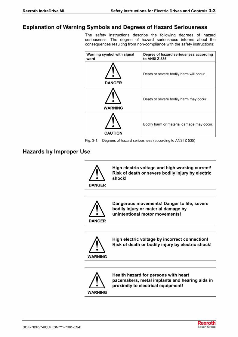
Explanation of Warning Symbols and Degrees of Hazard SeriousnessThe safety instructions describe the following degrees of hazardseriousness. The degree of hazard seriousness informs about theconsequences resulting from non-compliance with the safety instructions:
Warning symbol with signalword
Degree of hazard seriousness accordingto ANSI Z 535
DANGER
Death or severe bodily harm will occur.
WARNING
Death or severe bodily harm may occur.
CAUTION
Bodily harm or material damage may occur.
Fig. 3-1: Degrees of hazard seriousness (according to ANSI Z 535)
Hazards by Improper Use
DANGER
High electric voltage and high working current!Risk of death or severe bodily injury by electricshock!
DANGER
Dangerous movements! Danger to life, severebodily injury or material damage byunintentional motor movements!
WARNING
High electric voltage by incorrect connection!Risk of death or bodily injury by electric shock!
WARNING
Health hazard for persons with heartpacemakers, metal implants and hearing aids inproximity to electrical equipment!
3-4 Safety Instructions for Electric Drives and Controls Rexroth IndraDrive Mi
DOK-INDRV*-KCU+KSM****-PR01-EN-P
CAUTION
Hot surfaces on device housing! Danger ofinjury! Danger of burns!
CAUTION
Risk of injury by improper handling! Risk ofbodily injury by bruising, shearing, cutting,hitting or improper handling of pressurizedlines!
CAUTION
Risk of injury by improper handling of batteries!

Rexroth IndraDrive Mi Safety Instructions for Electric Drives and Controls 3-5
DOK-INDRV*-KCU+KSM****-PR01-EN-P
3.2 Instructions with Regard to Specific Dangers
Protection Against Contact with Electrical Parts
Note: This section only concerns devices and drive components withvoltages of more than 50 volts.
Contact with parts conducting voltages above 50 volts can cause personaldanger and electric shock. When operating electrical equipment, it isunavoidable that some parts of the devices conduct dangerous voltage.
DANGER
High electrical voltage! Danger to life, electricshock and severe bodily injury!⇒ Only those trained and qualified to work with or on
electrical equipment are permitted to operate,maintain and repair this equipment.
⇒ Follow general construction and safety regulationswhen working on electrical power installations.
⇒ Before switching on the device, the equipmentgrounding conductor must have been non-detachably connected to all electrical equipment inaccordance with the connection diagram.
⇒ Do not operate electrical equipment at any time,even for brief measurements or tests, if theequipment grounding conductor is not permanentlyconnected to the mounting points of the componentsprovided for this purpose.
⇒ Before working with electrical parts with voltagepotentials higher than 50 V, the device must bedisconnected from the mains voltage or powersupply unit. Provide a safeguard to preventreconnection.
3-6 Safety Instructions for Electric Drives and Controls Rexroth IndraDrive Mi
DOK-INDRV*-KCU+KSM****-PR01-EN-P
⇒ With electrical drive and filter components, observethe following:Wait 30 minutes after switching off power to allowcapacitors to discharge before beginning to work.Measure the voltage on the capacitors beforebeginning to work to make sure that the equipment issafe to touch.
⇒ Never touch the electrical connection points of acomponent while power is turned on.
⇒ Install the covers and guards provided with theequipment properly before switching the device on.Before switching the equipment on, cover andsafeguard live parts safely to prevent contact withthose parts.
⇒ A residual-current-operated circuit-breaker or r.c.d.cannot be used for electric drives! Indirect contactmust be prevented by other means, for example, byan overcurrent protective device according to therelevant standards.
⇒ Secure built-in devices from direct touching ofelectrical parts by providing an external housing, forexample a control cabinet.
European countries: according to EN 50178/ 1998,section 5.3.2.3.USA: See National Electrical Code (NEC), NationalElectrical Manufacturers' Association (NEMA), as well aslocal engineering regulations. The operator must observeall the above regulations at any time.
With electrical drive and filter components, observe the following:
DANGER
High housing voltage and high leakage current!Risk of death or bodily injury by electric shock!⇒ Before switching on, the housings of all electrical
equipment and motors must be connected orgrounded with the equipment grounding conductor tothe grounding points. This is also applicable beforeshort tests.
⇒ The equipment grounding conductor of the electricalequipment and the units must be non-detachablyand permanently connected to the power supply unitat all times. The leakage current is greater than3.5 mA.
⇒ Over the total length, use copper wire of a crosssection of a minimum of 10 mm2 for this equipmentgrounding connection!
⇒ Before start-up, also in trial runs, always attach theequipment grounding conductor or connect with theground wire. Otherwise, high voltages may occur atthe housing causing electric shock.
Rexroth IndraDrive Mi Safety Instructions for Electric Drives and Controls 3-7
DOK-INDRV*-KCU+KSM****-PR01-EN-P
Protection Against Electric Shock by Protective Extra-Low Voltage(PELV)
All connections and terminals with voltages between 5 and 50 volts atRexroth products are protective extra-low voltage systems which areprovided with touch guard according to the product standards.
WARNING
High electric voltage by incorrect connection!Risk of death or bodily injury by electric shock!⇒ To all connections and terminals with voltages
between 0 and 50 volts, only devices, electricalcomponents, and conductors may be connectedwhich are equipped with a PELV (Protective Extra-Low Voltage) system.
⇒ Connect only voltages and circuits which are safelyisolated from dangerous voltages. Safe isolation isachieved for example by isolating transformers, safeoptocouplers or battery operation without mainsconnection.
Protection Against Dangerous MovementsDangerous movements can be caused by faulty control of connectedmotors. Some common examples are:• improper or wrong wiring of cable connections• incorrect operation of the equipment components• wrong input of parameters before operation• malfunction of sensors, encoders and monitoring devices• defective components• software or firmware errorsDangerous movements can occur immediately after equipment isswitched on or even after an unspecified time of trouble-free operation.The monitoring in the drive components will normally be sufficient to avoidfaulty operation in the connected drives. Regarding personal safety,especially the danger of bodily harm and material damage, this alonecannot be relied upon to ensure complete safety. Until the integratedmonitoring functions become effective, it must be assumed in any casethat faulty drive movements will occur. The extent of faulty drivemovements depends upon the type of control and the state of operation.
3-8 Safety Instructions for Electric Drives and Controls Rexroth IndraDrive Mi
DOK-INDRV*-KCU+KSM****-PR01-EN-P
DANGER
Dangerous movements! Danger to life, risk ofinjury, severe bodily harm or material damage!⇒ For the above reasons, ensure personal safety by
means of qualified and tested higher-level monitoringdevices or measures integrated in the installation.They have to be provided for by the user accordingto the specific conditions within the installation and ahazard and fault analysis. The safety regulationsapplicable for the installation have to be taken intoconsideration. Unintended machine motion or othermalfunction is possible if safety devices are disabled,bypassed or not activated.
To avoid accidents, bodily harm and/or materialdamage:
⇒ Keep free and clear of the machine’s range ofmotion and moving parts. Possible measures toprevent people from accidentally entering themachine’s range of motion:- use safety fences- use safety guards- use protective coverings- install light curtains or light barriers
⇒ Fences and coverings must be strong enough toresist maximum possible momentum.
⇒ Mount the emergency stop switch in the immediatereach of the operator. Verify that the emergency stopworks before startup. Don’t operate the device if theemergency stop is not working.
⇒ Isolate the drive power connection by means of anemergency stop circuit or use a safety relatedstarting lockout to prevent unintentional start.
⇒ Make sure that the drives are brought to a safestandstill before accessing or entering the dangerzone.
⇒ Additionally secure vertical axes against falling ordropping after switching off the motor power by, forexample:- mechanically securing the vertical axes,- adding an external braking/ arrester/ clamping
mechanism or- ensuring sufficient equilibration of the vertical
axes.The standard equipment motor brake or an externalbrake controlled directly by the drive controller arenot sufficient to guarantee personal safety!
Rexroth IndraDrive Mi Safety Instructions for Electric Drives and Controls 3-9
DOK-INDRV*-KCU+KSM****-PR01-EN-P
⇒ Disconnect electrical power to the equipment using amaster switch and secure the switch againstreconnection for:- maintenance and repair work- cleaning of equipment- long periods of discontinued equipment use
⇒ Prevent the operation of high-frequency, remotecontrol and radio equipment near electronics circuitsand supply leads. If the use of such devices cannotbe avoided, verify the system and the installation forpossible malfunctions in all possible positions ofnormal use before initial startup. If necessary,perform a special electromagnetic compatibility(EMC) test on the installation.
Protection Against Magnetic and Electromagnetic Fields DuringOperation and Mounting
Magnetic and electromagnetic fields generated by current-carryingconductors and permanent magnets in motors represent a seriouspersonal danger to those with heart pacemakers, metal implants andhearing aids.
WARNING
Health hazard for persons with heartpacemakers, metal implants and hearing aids inproximity to electrical equipment!⇒ Persons with heart pacemakers and metal implants
are not permitted to enter following areas:- Areas in which electrical equipment and parts are
mounted, being operated or commissioned.- Areas in which parts of motors with permanent
magnets are being stored, repaired or mounted.⇒ If it is necessary for somebody with a pacemaker to
enter such an area, a doctor must be consulted priorto doing so. The interference immunity of present orfuture implanted heart pacemakers differs greatly, sothat no general rules can be given.
⇒ Those with metal implants or metal pieces, as wellas with hearing aids must consult a doctor beforethey enter the areas described above. Otherwisehealth hazards may occur.
3-10 Safety Instructions for Electric Drives and Controls Rexroth IndraDrive Mi
DOK-INDRV*-KCU+KSM****-PR01-EN-P
Protection Against Contact with Hot Parts
CAUTION
Hot surfaces at motor housings, on drivecontrollers or chokes! Danger of injury! Dangerof burns!⇒ Do not touch surfaces of device housings and
chokes in the proximity of heat sources! Danger ofburns!
⇒ Do not touch housing surfaces of motors! Danger ofburns!
⇒ According to operating conditions, temperatures canbe higher than 60 °C, 140 °F during or afteroperation.
⇒ Before accessing motors after having switched themoff, let them cool down for a sufficiently long time.Cooling down can require up to 140 minutes!Roughly estimated, the time required for coolingdown is five times the thermal time constantspecified in the Technical Data.
⇒ After switching drive controllers or chokes off, wait15 minutes to allow them to cool down beforetouching them.
⇒ Wear safety gloves or do not work at hot surfaces.⇒ For certain applications, the manufacturer of the end
product, machine or installation, according to therespective safety regulations, has to take measuresto avoid injuries caused by burns in the endapplication. These measures can be, for example:warnings, guards (shielding or barrier), technicaldocumentation.
Rexroth IndraDrive Mi Safety Instructions for Electric Drives and Controls 3-11
DOK-INDRV*-KCU+KSM****-PR01-EN-P
Protection During Handling and MountingIn unfavorable conditions, handling and assembling certain parts andcomponents in an improper way can cause injuries.
CAUTION
Risk of injury by improper handling! Bodilyinjury by bruising, shearing, cutting, hitting!⇒ Observe the general construction and safety
regulations on handling and assembly.⇒ Use suitable devices for assembly and transport.⇒ Avoid jamming and bruising by appropriate
measures.⇒ Always use suitable tools. Use special tools if
specified.⇒ Use lifting equipment and tools in the correct
manner.⇒ If necessary, use suitable protective equipment (for
example safety goggles, safety shoes, safetygloves).
⇒ Do not stand under hanging loads.⇒ Immediately clean up any spilled liquids because of
the danger of skidding.
Battery SafetyBatteries consist of active chemicals enclosed in a solid housing.Therefore, improper handling can cause injury or damages.
CAUTION
Risk of injury by improper handling!⇒ Do not attempt to reactivate low batteries by heating
or other methods (risk of explosion andcauterization).
⇒ Do not recharge the batteries as this may causeleakage or explosion.
⇒ Do not throw batteries into open flames.⇒ Do not dismantle batteries.⇒ Do not damage electrical parts installed in the
devices.
Note: Environmental protection and disposal! The batteries installedin the product are considered dangerous goods during land,air, and sea transport (risk of explosion) in the sense of thelegal regulations. Dispose of used batteries separately fromother waste. Observe the local regulations in the country ofassembly.
3-12 Safety Instructions for Electric Drives and Controls Rexroth IndraDrive Mi
DOK-INDRV*-KCU+KSM****-PR01-EN-P
Protection Against Pressurized SystemsAccording to the information given in the Project Planning Manuals,motors cooled with liquid and compressed air, as well as drive controllers,can be partially supplied with externally fed, pressurized media, such ascompressed air, hydraulics oil, cooling liquids, and cooling lubricatingagents. In these cases, improper handling of external supply systems,supply lines, or connections can cause injuries or damages.
CAUTION
Risk of injury by improper handling of pressurizedlines!⇒ Do not attempt to disconnect, open, or cut
pressurized lines (risk of explosion).⇒ Observe the respective manufacturer's operating
instructions.⇒ Before dismounting lines, relieve pressure and
empty medium.⇒ Use suitable protective equipment (for example
safety goggles, safety shoes, safety gloves).⇒ Immediately clean up any spilled liquids from the
floor.
Note: Environmental protection and disposal! The agents used tooperate the product might not be economically friendly.Dispose of ecologically harmful agents separately from otherwaste. Observe the local regulations in the country ofassembly.
Rexroth IndraDrive Mi General Specification of the Components 4-1
DOK-INDRV*-KCU+KSM****-PR01-EN-P
4 General Specification of the Components
4.1 CertificationsFor the components, there are declarations of conformity available whichconfirm that the components have been designed according to the validEN standards and EC directives. If required, our sales representative canprovide you with the declarations of conformity.
Designation StandardCE conformity regarding Low-Voltage Directive EN61800-5-1
CE conformity regarding EMC product standard EN61800-3
listing according to UL standard (UL) UL 508 C (in preparation)
Fig. 4-1: Applied standards
Note: Before making a high-voltage test for the installation in whichthe components are used, disconnect all connections to thedevices or disconnect the plug-in connections to protect theelectronic components.
Fig. 4-2: CE label
in preparation
Declaration of Conformity
CE Label
C-UL-US Listing
4-2 General Specification of the Components Rexroth IndraDrive Mi
DOK-INDRV*-KCU+KSM****-PR01-EN-P
4.2 Transport and Storage
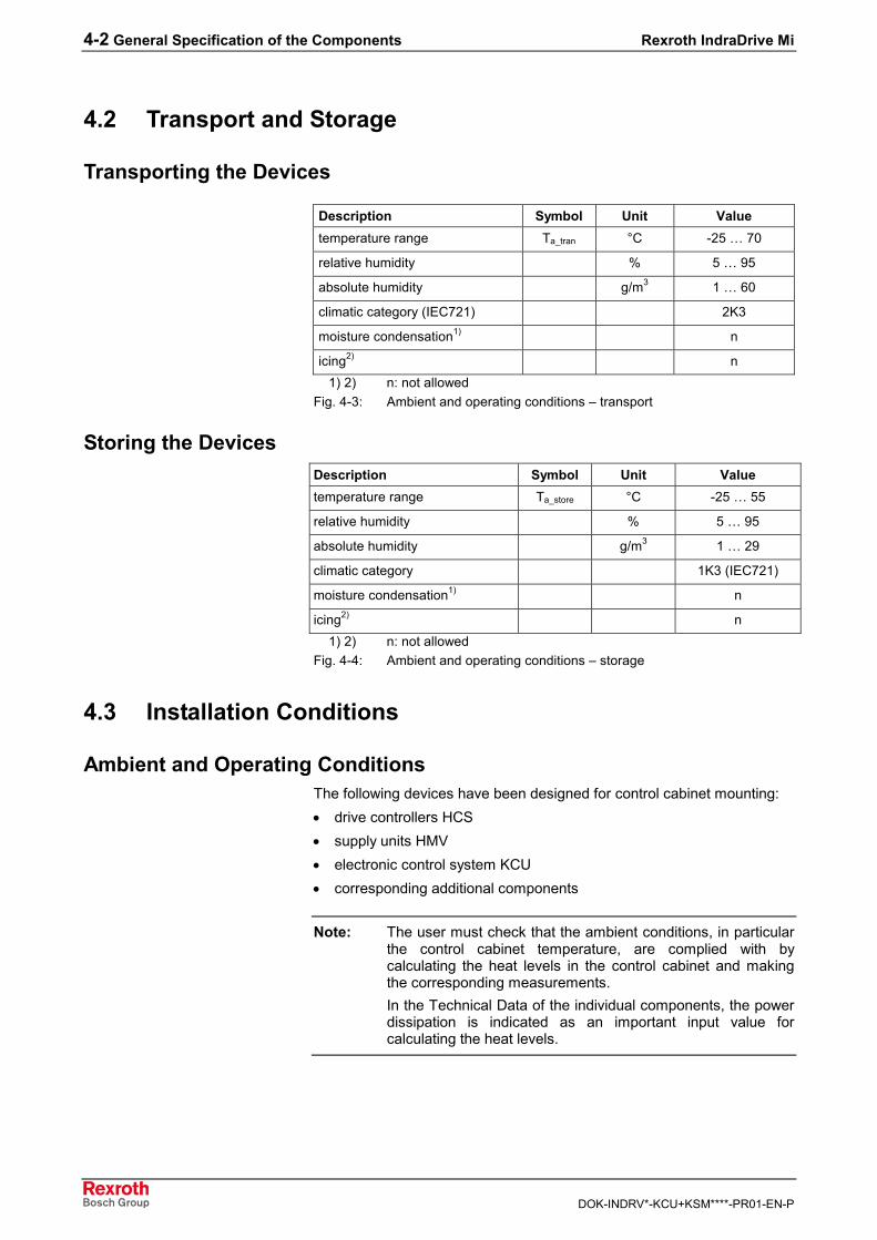
Transporting the Devices
Description Symbol Unit Valuetemperature range Ta_tran °C -25 … 70
relative humidity % 5 … 95
absolute humidity g/m3 1 … 60
climatic category (IEC721) 2K3
moisture condensation1) n
icing2) n1) 2) n: not allowed
Fig. 4-3: Ambient and operating conditions – transport
Storing the DevicesDescription Symbol Unit Valuetemperature range Ta_store °C -25 … 55
relative humidity % 5 … 95
absolute humidity g/m3 1 … 29
climatic category 1K3 (IEC721)
moisture condensation1) n
icing2) n1) 2) n: not allowed
Fig. 4-4: Ambient and operating conditions – storage
4.3 Installation Conditions
Ambient and Operating ConditionsThe following devices have been designed for control cabinet mounting:• drive controllers HCS• supply units HMV• electronic control system KCU• corresponding additional components
Note: The user must check that the ambient conditions, in particularthe control cabinet temperature, are complied with bycalculating the heat levels in the control cabinet and makingthe corresponding measurements.In the Technical Data of the individual components, the powerdissipation is indicated as an important input value forcalculating the heat levels.
Rexroth IndraDrive Mi General Specification of the Components 4-3
DOK-INDRV*-KCU+KSM****-PR01-EN-P
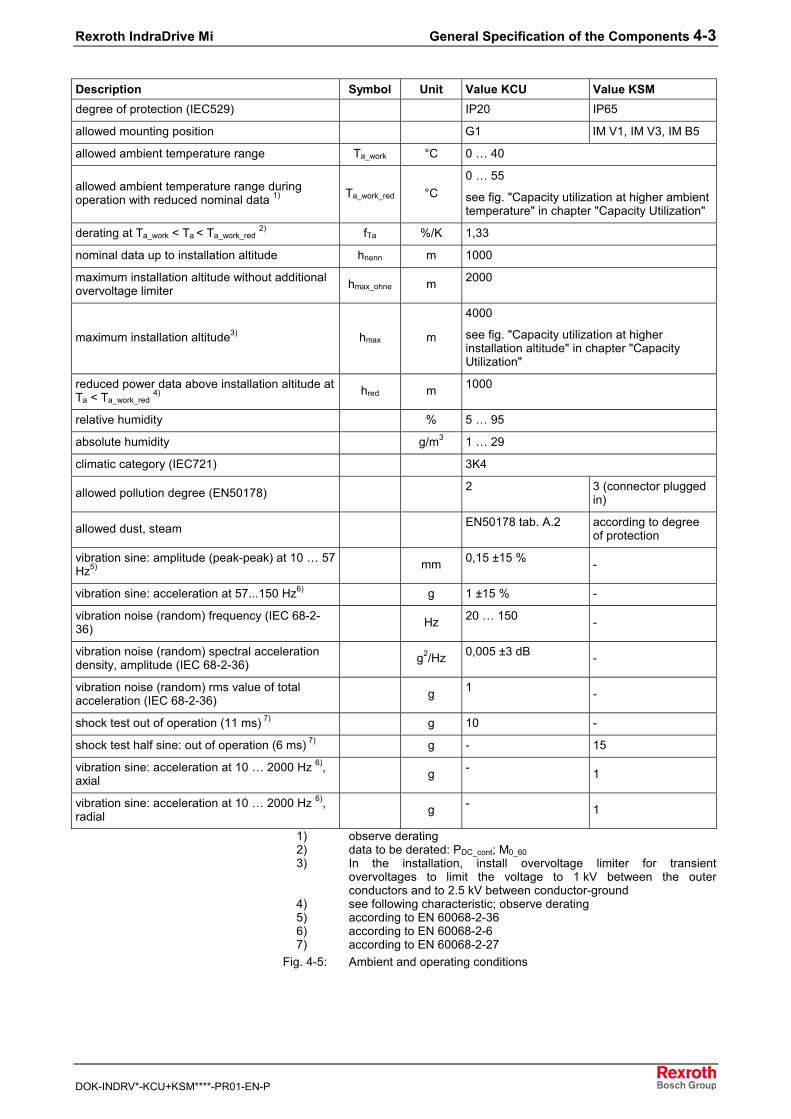
Description Symbol Unit Value KCU Value KSMdegree of protection (IEC529) IP20 IP65
allowed mounting position G1 IM V1, IM V3, IM B5
allowed ambient temperature range Ta_work °C 0 … 40
allowed ambient temperature range duringoperation with reduced nominal data 1) Ta_work_red °C
0 … 55
see fig. "Capacity utilization at higher ambienttemperature" in chapter "Capacity Utilization"
derating at Ta_work < Ta < Ta_work_red 2) fTa %/K 1,33
nominal data up to installation altitude hnenn m 1000
maximum installation altitude without additionalovervoltage limiter hmax_ohne m 2000
maximum installation altitude3) hmax m
4000
see fig. "Capacity utilization at higherinstallation altitude" in chapter "CapacityUtilization"
reduced power data above installation altitude atTa < Ta_work_red 4) hred m 1000
relative humidity % 5 … 95
absolute humidity g/m3 1 … 29
climatic category (IEC721) 3K4
allowed pollution degree (EN50178) 2 3 (connector pluggedin)
allowed dust, steam EN50178 tab. A.2 according to degreeof protection
vibration sine: amplitude (peak-peak) at 10 … 57Hz5) mm 0,15 ±15 % -
vibration sine: acceleration at 57...150 Hz6) g 1 ±15 % -
vibration noise (random) frequency (IEC 68-2-36) Hz 20 … 150 -
vibration noise (random) spectral accelerationdensity, amplitude (IEC 68-2-36) g2/Hz 0,005 ±3 dB -
vibration noise (random) rms value of totalacceleration (IEC 68-2-36) g 1 -
shock test out of operation (11 ms) 7) g 10 -
shock test half sine: out of operation (6 ms) 7) g - 15
vibration sine: acceleration at 10 … 2000 Hz 6),axial g - 1
vibration sine: acceleration at 10 … 2000 Hz 6),radial g - 1
1) observe derating2) data to be derated: PDC_cont; M0_603) In the installation, install overvoltage limiter for transient
overvoltages to limit the voltage to 1 kV between the outerconductors and to 2.5 kV between conductor-ground
4) see following characteristic; observe derating5) according to EN 60068-2-366) according to EN 60068-2-67) according to EN 60068-2-27
Fig. 4-5: Ambient and operating conditions
4-4 General Specification of the Components Rexroth IndraDrive Mi
DOK-INDRV*-KCU+KSM****-PR01-EN-P
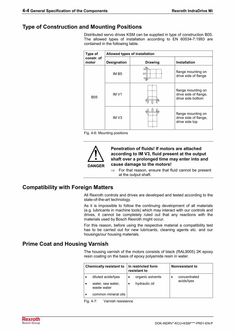
Type of Construction and Mounting PositionsDistributed servo drives KSM can be supplied in type of construction B05.The allowed types of installation according to EN 60034-7:1993 arecontained in the following table.
Allowed types of installationType ofconstr. ofmotor Designation Drawing Installation
IM B5 flange mounting ondrive side of flange
IM V1flange mounting ondrive side of flange,drive side bottomB05
IM V3flange mounting ondrive side of flange,drive side top
Fig. 4-6: Mounting positions
DANGER
Penetration of fluids! If motors are attachedaccording to IM V3, fluid present at the outputshaft over a prolonged time may enter into andcause damage to the motors!⇒ For that reason, ensure that fluid cannot be present
at the output shaft.
Compatibility with Foreign MattersAll Rexroth controls and drives are developed and tested according to thestate-of-the-art technology.As it is impossible to follow the continuing development of all materials(e.g. lubricants in machine tools) which may interact with our controls anddrives, it cannot be completely ruled out that any reactions with thematerials used by Bosch Rexroth might occur.For this reason, before using the respective material a compatibility testhas to be carried out for new lubricants, cleaning agents etc. and ourhousings/our housing materials.
Prime Coat and Housing VarnishThe housing varnish of the motors consists of black (RAL9005) 2K epoxyresin coating on the basis of epoxy polyamide resin in water.
Chemically resistant to In restricted formresistant to
Nonresistant to
• diluted acids/lyes
• water, sea water,waste water
• common mineral oils
• organic solvents
• hydraulic oil
• concentratedacids/lyes
Fig. 4-7: Varnish resistance
Rexroth IndraDrive Mi General Specification of the Components 4-5
DOK-INDRV*-KCU+KSM****-PR01-EN-P
It is permitted to provide the housing with additional varnish with amaximum coat thickness of 40 µm. Before varnishing, verify the adhesionand resistance of the new varnish.
4.4 Capacity UtilizationWhere installation conditions differ, the following performance data arereduced in accordance with the diagrams:Motor:• power• continuous torque at standstill• S1 continuous torques• short-time service torque MKB
If differing ambient temperatures and higher installation altitudes occursimultaneously, both capacity utilization factors must be multiplied. Theinstallation altitude must only be taken into account once, deviatingambient temperatures must be taken into account separately for motorand drive controller.
Note: Use outside of the indicated installation conditions is notallowed, even if the performance data are additionallyreduced.
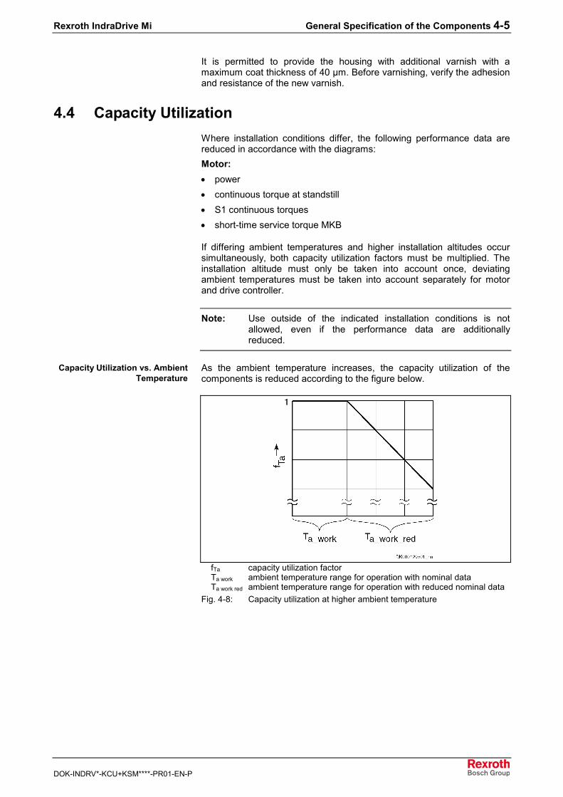
As the ambient temperature increases, the capacity utilization of thecomponents is reduced according to the figure below.
fTa capacity utilization factorTa work ambient temperature range for operation with nominal dataTa work red ambient temperature range for operation with reduced nominal data
Fig. 4-8: Capacity utilization at higher ambient temperature
Capacity Utilization vs. AmbientTemperature
4-6 General Specification of the Components Rexroth IndraDrive Mi
DOK-INDRV*-KCU+KSM****-PR01-EN-P
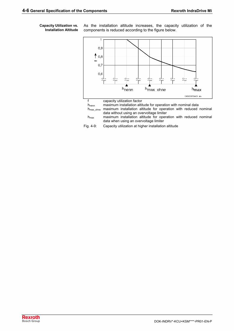
As the installation altitude increases, the capacity utilization of thecomponents is reduced according to the figure below.
f capacity utilization factorhnenn maximum installation altitude for operation with nominal datahmax_ohne maximum installation altitude for operation with reduced nominal
data without using an overvoltage limiterhmax maximum installation altitude for operation with reduced nominal
data when using an overvoltage limiterFig. 4-9: Capacity utilization at higher installation altitude
Capacity Utilization vs.Installation Altitude
Rexroth IndraDrive Mi Technical Data of the Components 5-1
DOK-INDRV*-KCU+KSM****-PR01-EN-P
5 Technical Data of the Components
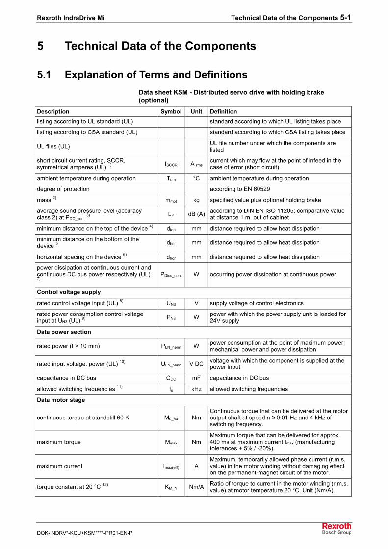
5.1 Explanation of Terms and DefinitionsData sheet KSM - Distributed servo drive with holding brake(optional)
Description Symbol Unit Definitionlisting according to UL standard (UL) standard according to which UL listing takes place
listing according to CSA standard (UL) standard according to which CSA listing takes place
UL files (UL) UL file number under which the components arelisted
short circuit current rating, SCCR,symmetrical amperes (UL) 1) ISCCR A rms
current which may flow at the point of infeed in thecase of error (short circuit)
ambient temperature during operation Tum °C ambient temperature during operation
degree of protection according to EN 60529
mass 2) mmot kg specified value plus optional holding brake
average sound pressure level (accuracyclass 2) at PDC_cont 3) LP dB (A) according to DIN EN ISO 11205; comparative value
at distance 1 m, out of cabinet
minimum distance on the top of the device 4) dtop mm distance required to allow heat dissipation
minimum distance on the bottom of thedevice 5 dbot mm distance required to allow heat dissipation
horizontal spacing on the device 6) dhor mm distance required to allow heat dissipation
power dissipation at continuous current andcontinuous DC bus power respectively (UL)7)
PDiss_cont W occurring power dissipation at continuous power
Control voltage supply
rated control voltage input (UL) 8) UN3 V supply voltage of control electronics
rated power consumption control voltageinput at UN3 (UL) 9) PN3 W power with which the power supply unit is loaded for
24V supply
Data power section
rated power (t > 10 min) PLN_nenn W power consumption at the point of maximum power;mechanical power and power dissipation
rated input voltage, power (UL) 10) ULN_nenn V DC voltage with which the component is supplied at thepower input
capacitance in DC bus CDC mF capacitance in DC bus
allowed switching frequencies 11) fs kHz allowed switching frequencies
Data motor stage
continuous torque at standstill 60 K M0_60 NmContinuous torque that can be delivered at the motoroutput shaft at speed n ≥ 0.01 Hz and 4 kHz ofswitching frequency.
maximum torque Mmax NmMaximum torque that can be delivered for approx.400 ms at maximum current Imax (manufacturingtolerances + 5% / -20%).
maximum current Imax(eff) AMaximum, temporarily allowed phase current (r.m.s.value) in the motor winding without damaging effecton the permanent-magnet circuit of the motor.
torque constant at 20 °C 12) KM_N Nm/A Ratio of torque to current in the motor winding (r.m.s.value) at motor temperature 20 °C. Unit (Nm/A).
5-2 Technical Data of the Components Rexroth IndraDrive Mi
DOK-INDRV*-KCU+KSM****-PR01-EN-P
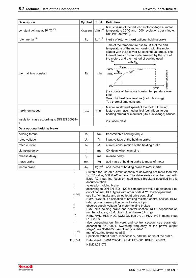
Description Symbol Unit Definition
constant voltage at 20 °C 13) KEMK_1000 V/min-1R.m.s. value of the induced motor voltage at motortemperature 20 °C and 1000 revolutions per minute.Unit (V/1000min-1).
rotor inertia 14) Jrot kg*m2 inertia of rotor without optional holding brake
thermal time constant Tth min
Time of the temperature rise to 63% of the endtemperature of the motor housing with the motorloaded with the allowed S1 continuous torque. Thethermal time constant is determined by the size ofthe motors and the method of cooling used.
(1): course of the motor housing temperature overtimeΘmax: highest temperature (motor housing)Tth: thermal time constant
maximum speed nmax min-1Maximum allowed speed of the motor. Limitingfactors can have mechanical (centrifugal forces,bearing stress) or electrical (DC bus voltage) causes.
insulation class according to DIN EN 60034–1 insulation class
Data optional holding brake
holding torque M4 Nm transmittable holding torque
rated voltage UN V input voltage of the holding brake
rated current IN A current consumption of the holding brake
clamping delay t1 ms ON delay when clamping
release delay t2 ms release delay
mass brake mBr kg add mass of holding brake to mass of motor
inertia brake Jrot kg*m2 add inertia of holding brake to rotor inertia1) Suitable for use on a circuit capable of delivering not more than this
SCCR value, 600 V AC or less. The drive series shall be used withlisted AC input line fuses or listed circuit breakers specified in thisdocumentation.
2) value plus holding brake3) according to DIN EN ISO 11205; comparative value at distance 1 m,
out of cabinet; HCS types with order code -L***: load-dependent4) 5) 6) see fig. "Air intake and air outlet at drive controller"7) HMV, HCS: plus dissipation of braking resistor, control section; KSM:
rated power consumption control voltage input8) observe supply voltage for motor holding brakes9) HMx: plus holding brake and control section; KCU: dependent on
number of axes; KSM: plus holding brake (UN x IN)10) HMS, HMD, HLB, HLC, KCU: DC bus L+, L-; HMV, HCS: mains input
L1, L2, L311) also depending on firmware and control section; see parameter
description "P-0-0001, Switching frequency of the power outputstage"; see "P-0-4058, Amplifier type data"
12) 13) manufacturing tolerance ±5%14) Specified without brake. If necessary, add the inertia of the brake.
Fig. 5-1: Data sheet KSM01.2B-041, KSM01.2B-061, KSM01.2B-071,KSM01.2B-076
Rexroth IndraDrive Mi Technical Data of the Components 5-3
DOK-INDRV*-KCU+KSM****-PR01-EN-P
The motor data and characteristics are determined under the followingconditions:• ambient temperature 40 °C• insulated structure (aluminum flange)• Amplifier temperature P-0-0384 = 100 °C (∆T = 60 K); this
temperature is slightly higher than the temperature of the motorhousing.
• switching frequency 4 kHz (at 8 kHz reduced continuous torque andpeak torque)
• motors with radial shaft sealing ring
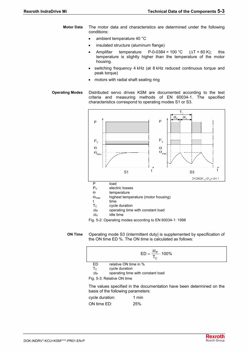
Distributed servo drives KSM are documented according to the testcriteria and measuring methods of EN 60034-1. The specifiedcharacteristics correspond to operating modes S1 or S3.
P loadPV electric lossesΘ temperatureΘmax highest temperature (motor housing)t timeTC cycle duration∆tP operating time with constant load∆tV idle time
Fig. 5-2: Operating modes according to EN 60034-1: 1998
Operating mode S3 (intermittent duty) is supplemented by specification ofthe ON time ED %. The ON time is calculated as follows:
%100Tt
EDC
P ⋅=∆
ED relative ON time in %TC cycle duration∆tP operating time with constant load
Fig. 5-3: Relative ON time
The values specified in the documentation have been determined on thebasis of the following parameters:cycle duration: 1 minON time ED: 25%
Motor Data
Operating Modes
ON Time
5-4 Technical Data of the Components Rexroth IndraDrive Mi
DOK-INDRV*-KCU+KSM****-PR01-EN-P
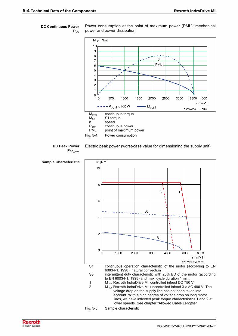
Power consumption at the point of maximum power (PML); mechanicalpower and power dissipation
Mcont continuous torqueMS1 S1 torquen speedPcont continuous powerPML point of maximum power
Fig. 5-4: Power consumption
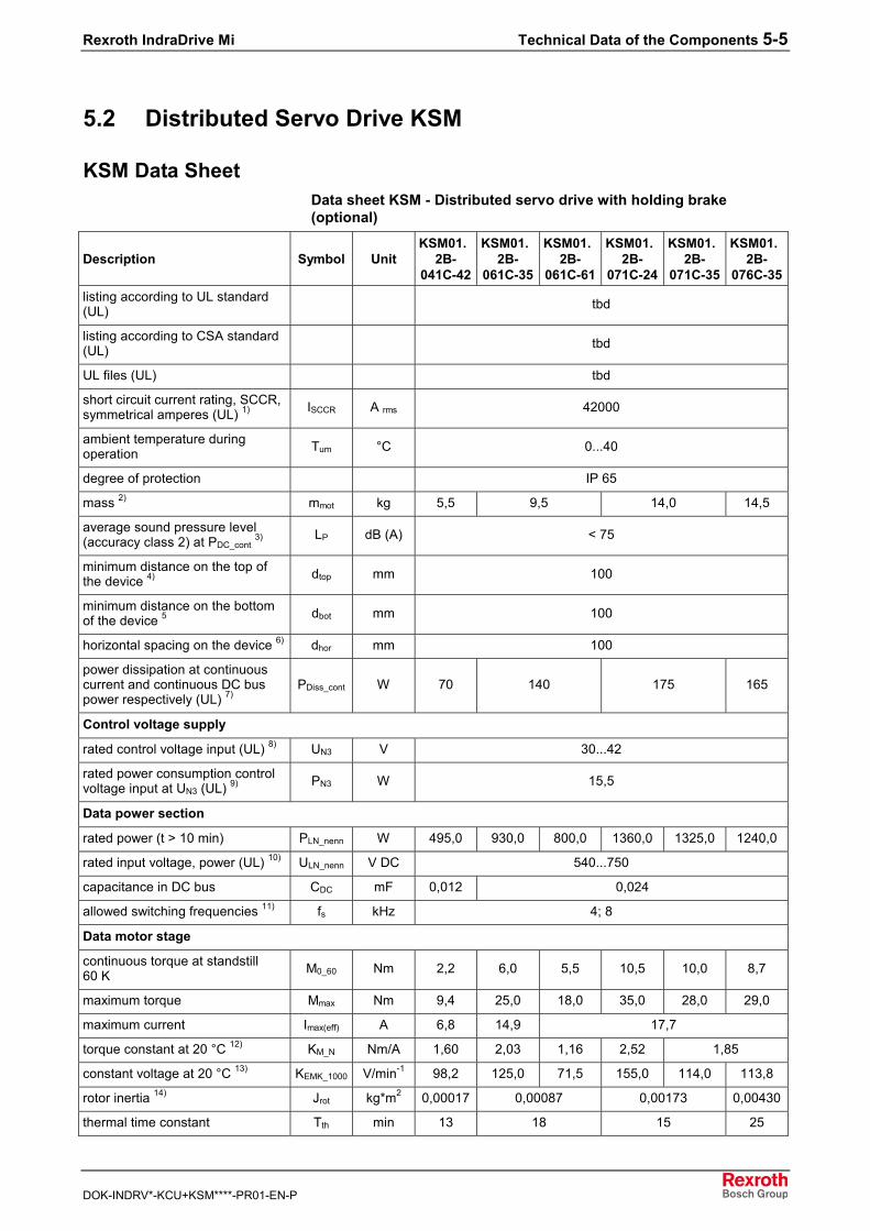
Electric peak power (worst-case value for dimensioning the supply unit)
S1 continuous operation characteristic of the motor (according to EN60034-1; 1998), natural convection
S3 intermittent duty characteristic with 25% ED of the motor (accordingto EN 60034-1; 1998) and max. cycle duration 1 min.
1 Mmax Rexroth IndraDrive Mi, controlled infeed DC 750 V2 Mmax Rexroth IndraDrive Mi, uncontrolled infeed 3 × AC 400 V. The
voltage drop on the supply line has not been taken intoaccount. With a high degree of voltage drop on long motorlines, we have inflected peak torque characteristics 1 and 2 atlower speeds. See chapter "Allowed Cable Lengths"
Fig. 5-5: Sample characteristic
DC Continuous PowerPDC
DC Peak PowerPDC_max
Sample Characteristic
Rexroth IndraDrive Mi Technical Data of the Components 5-5
DOK-INDRV*-KCU+KSM****-PR01-EN-P
5.2 Distributed Servo Drive KSM
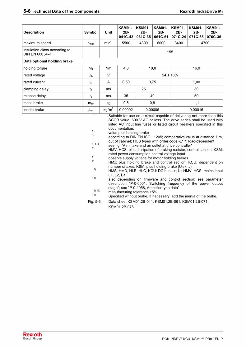
KSM Data SheetData sheet KSM - Distributed servo drive with holding brake(optional)
Description Symbol UnitKSM01.
2B-041C-42
KSM01.2B-
061C-35
KSM01.2B-
061C-61
KSM01.2B-
071C-24
KSM01.2B-
071C-35
KSM01.2B-
076C-35listing according to UL standard(UL) tbd
listing according to CSA standard(UL) tbd
UL files (UL) tbd
short circuit current rating, SCCR,symmetrical amperes (UL) 1) ISCCR A rms 42000
ambient temperature duringoperation Tum °C 0...40
degree of protection IP 65
mass 2) mmot kg 5,5 9,5 14,0 14,5
average sound pressure level(accuracy class 2) at PDC_cont 3) LP dB (A) < 75
minimum distance on the top ofthe device 4) dtop mm 100
minimum distance on the bottomof the device 5 dbot mm 100
horizontal spacing on the device 6) dhor mm 100
power dissipation at continuouscurrent and continuous DC buspower respectively (UL) 7)
PDiss_cont W 70 140 175 165
Control voltage supply
rated control voltage input (UL) 8) UN3 V 30...42
rated power consumption controlvoltage input at UN3 (UL) 9) PN3 W 15,5
Data power section
rated power (t > 10 min) PLN_nenn W 495,0 930,0 800,0 1360,0 1325,0 1240,0
rated input voltage, power (UL) 10) ULN_nenn V DC 540...750
capacitance in DC bus CDC mF 0,012 0,024
allowed switching frequencies 11) fs kHz 4; 8
Data motor stage
continuous torque at standstill60 K M0_60 Nm 2,2 6,0 5,5 10,5 10,0 8,7
maximum torque Mmax Nm 9,4 25,0 18,0 35,0 28,0 29,0
maximum current Imax(eff) A 6,8 14,9 17,7
torque constant at 20 °C 12) KM_N Nm/A 1,60 2,03 1,16 2,52 1,85
constant voltage at 20 °C 13) KEMK_1000 V/min-1 98,2 125,0 71,5 155,0 114,0 113,8
rotor inertia 14) Jrot kg*m2 0,00017 0,00087 0,00173 0,00430
thermal time constant Tth min 13 18 15 25
5-6 Technical Data of the Components Rexroth IndraDrive Mi
DOK-INDRV*-KCU+KSM****-PR01-EN-P
Description Symbol UnitKSM01.
2B-041C-42
KSM01.2B-
061C-35
KSM01.2B-
061C-61
KSM01.2B-
071C-24
KSM01.2B-
071C-35
KSM01.2B-
076C-35maximum speed nmax min-1 5500 4300 6000 3400 4700
insulation class according toDIN EN 60034–1 155
Data optional holding brake
holding torque M4 Nm 4,0 10,0 16,0
rated voltage UN V 24 ± 10%
rated current IN A 0,50 0,75 1,00
clamping delay t1 ms 25 30
release delay t2 ms 35 40 50
mass brake mBr kg 0,5 0,8 1,1
inertia brake Jrot kg*m2 0,00002 0,00006 0,000161) Suitable for use on a circuit capable of delivering not more than this
SCCR value, 600 V AC or less. The drive series shall be used withlisted AC input line fuses or listed circuit breakers specified in thisdocumentation.
2) value plus holding brake3) according to DIN EN ISO 11205; comparative value at distance 1 m,
out of cabinet; HCS types with order code -L***: load-dependent4) 5) 6) see fig. "Air intake and air outlet at drive controller"7) HMV, HCS: plus dissipation of braking resistor, control section; KSM:
rated power consumption control voltage input8) observe supply voltage for motor holding brakes9) HMx: plus holding brake and control section; KCU: dependent on
number of axes; KSM: plus holding brake (UN x IN)10) HMS, HMD, HLB, HLC, KCU: DC bus L+, L-; HMV, HCS: mains input
L1, L2, L311) also depending on firmware and control section; see parameter
description "P-0-0001, Switching frequency of the power outputstage"; see "P-0-4058, Amplifier type data"
12) 13) manufacturing tolerance ±5%14) Specified without brake. If necessary, add the inertia of the brake.
Fig. 5-6: Data sheet KSM01.2B-041, KSM01.2B-061, KSM01.2B-071,KSM01.2B-076
Rexroth IndraDrive Mi Technical Data of the Components 5-7
DOK-INDRV*-KCU+KSM****-PR01-EN-P
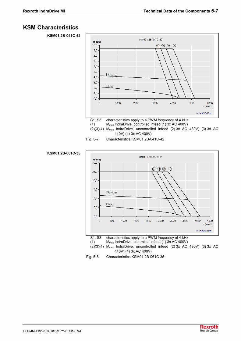
KSM Characteristics
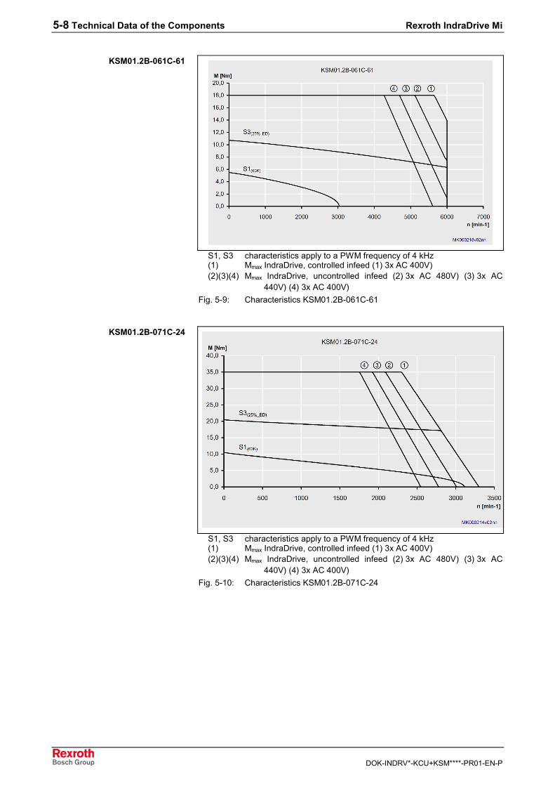
S1, S3 characteristics apply to a PWM frequency of 4 kHz(1) Mmax IndraDrive, controlled infeed (1) 3x AC 400V)(2)(3)(4) Mmax IndraDrive, uncontrolled infeed (2) 3x AC 480V) (3) 3x AC
440V) (4) 3x AC 400V)Fig. 5-7: Characteristics KSM01.2B-041C-42
S1, S3 characteristics apply to a PWM frequency of 4 kHz(1) Mmax IndraDrive, controlled infeed (1) 3x AC 400V)(2)(3)(4) Mmax IndraDrive, uncontrolled infeed (2) 3x AC 480V) (3) 3x AC
440V) (4) 3x AC 400V)Fig. 5-8: Characteristics KSM01.2B-061C-35
KSM01.2B-041C-42
KSM01.2B-061C-35
5-8 Technical Data of the Components Rexroth IndraDrive Mi
DOK-INDRV*-KCU+KSM****-PR01-EN-P
S1, S3 characteristics apply to a PWM frequency of 4 kHz(1) Mmax IndraDrive, controlled infeed (1) 3x AC 400V)(2)(3)(4) Mmax IndraDrive, uncontrolled infeed (2) 3x AC 480V) (3) 3x AC
440V) (4) 3x AC 400V)Fig. 5-9: Characteristics KSM01.2B-061C-61
S1, S3 characteristics apply to a PWM frequency of 4 kHz(1) Mmax IndraDrive, controlled infeed (1) 3x AC 400V)(2)(3)(4) Mmax IndraDrive, uncontrolled infeed (2) 3x AC 480V) (3) 3x AC
440V) (4) 3x AC 400V)Fig. 5-10: Characteristics KSM01.2B-071C-24
KSM01.2B-061C-61
KSM01.2B-071C-24
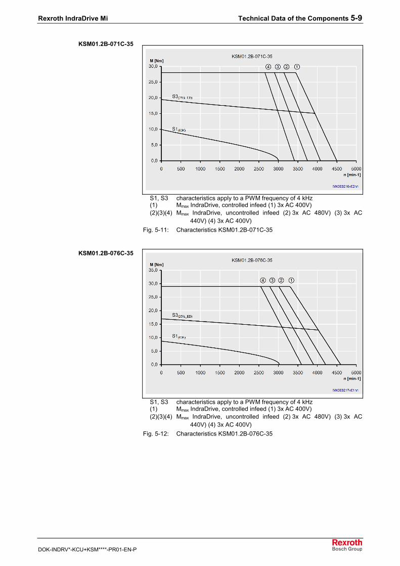
Rexroth IndraDrive Mi Technical Data of the Components 5-9
DOK-INDRV*-KCU+KSM****-PR01-EN-P
S1, S3 characteristics apply to a PWM frequency of 4 kHz(1) Mmax IndraDrive, controlled infeed (1) 3x AC 400V)(2)(3)(4) Mmax IndraDrive, uncontrolled infeed (2) 3x AC 480V) (3) 3x AC
440V) (4) 3x AC 400V)Fig. 5-11: Characteristics KSM01.2B-071C-35
S1, S3 characteristics apply to a PWM frequency of 4 kHz(1) Mmax IndraDrive, controlled infeed (1) 3x AC 400V)(2)(3)(4) Mmax IndraDrive, uncontrolled infeed (2) 3x AC 480V) (3) 3x AC
440V) (4) 3x AC 400V)Fig. 5-12: Characteristics KSM01.2B-076C-35
KSM01.2B-071C-35
KSM01.2B-076C-35
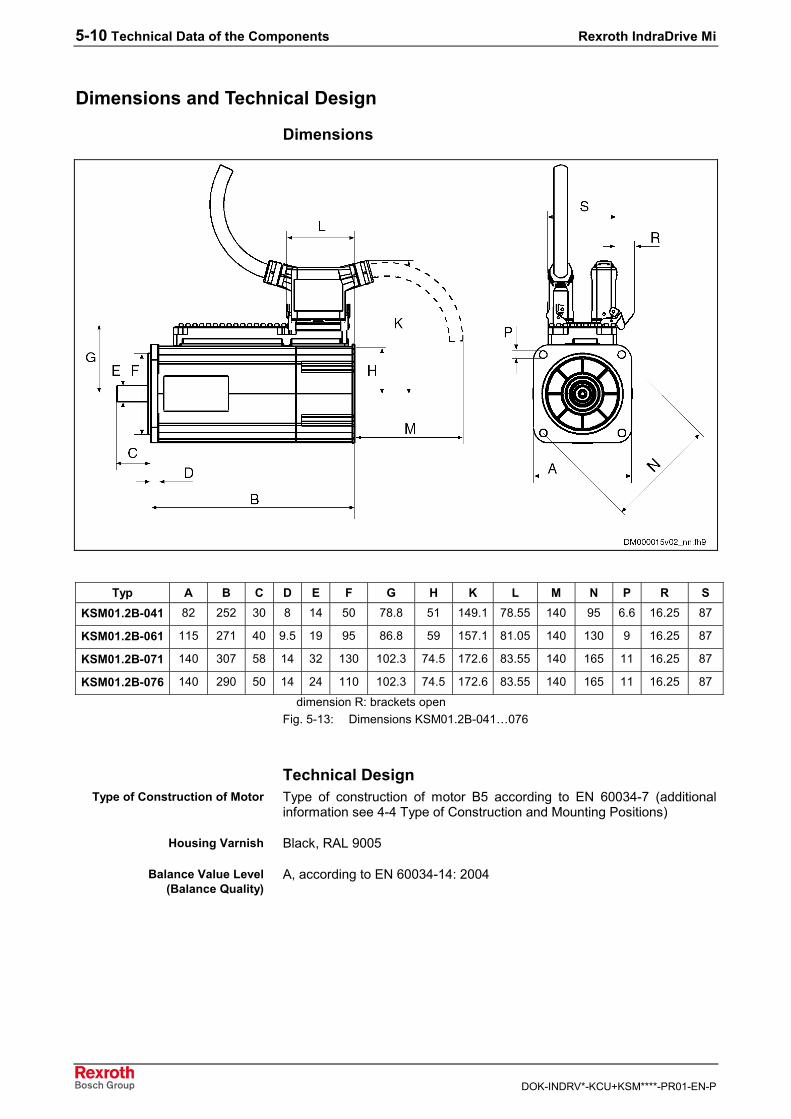
5-10 Technical Data of the Components Rexroth IndraDrive Mi
DOK-INDRV*-KCU+KSM****-PR01-EN-P
Dimensions and Technical Design
Dimensions
Typ A B C D E F G H K L M N P R SKSM01.2B-041 82 252 30 8 14 50 78.8 51 149.1 78.55 140 95 6.6 16.25 87
KSM01.2B-061 115 271 40 9.5 19 95 86.8 59 157.1 81.05 140 130 9 16.25 87
KSM01.2B-071 140 307 58 14 32 130 102.3 74.5 172.6 83.55 140 165 11 16.25 87
KSM01.2B-076 140 290 50 14 24 110 102.3 74.5 172.6 83.55 140 165 11 16.25 87
dimension R: brackets openFig. 5-13: Dimensions KSM01.2B-041…076
Technical DesignType of construction of motor B5 according to EN 60034-7 (additionalinformation see 4-4 Type of Construction and Mounting Positions)
Black, RAL 9005
A, according to EN 60034-14: 2004
Type of Construction of Motor
Housing Varnish
Balance Value Level(Balance Quality)
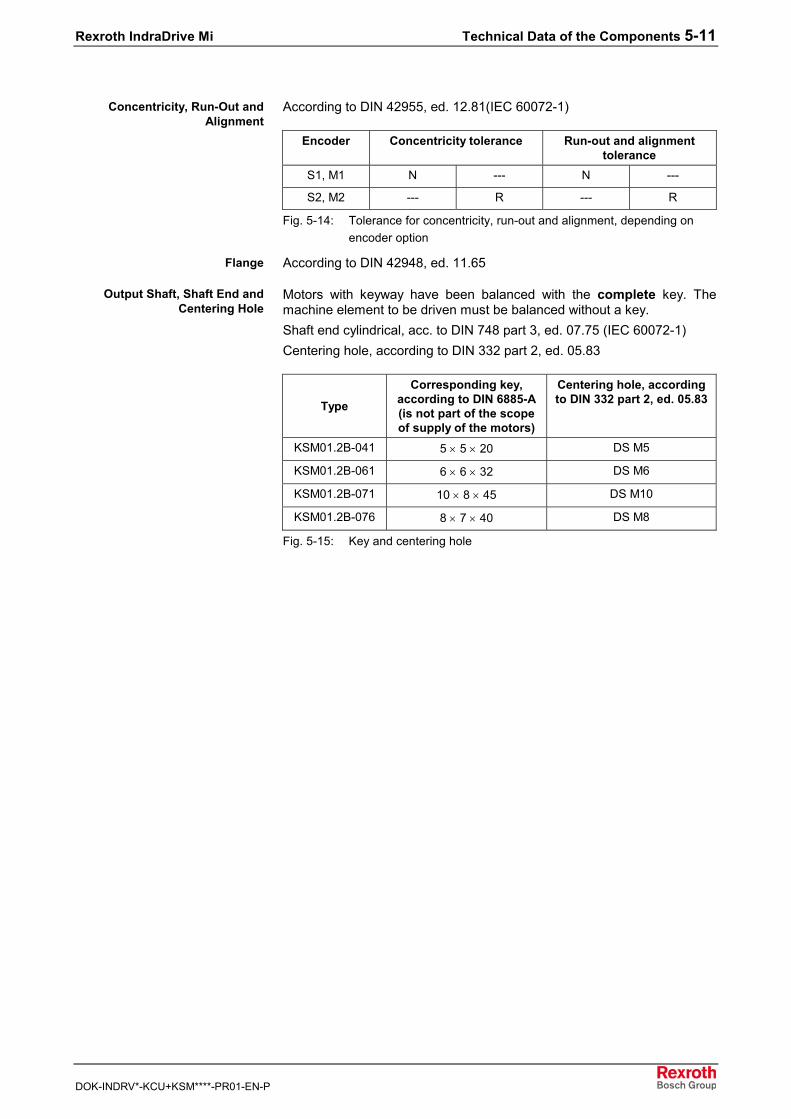
Rexroth IndraDrive Mi Technical Data of the Components 5-11
DOK-INDRV*-KCU+KSM****-PR01-EN-P
According to DIN 42955, ed. 12.81(IEC 60072-1)
Encoder Concentricity tolerance Run-out and alignmenttolerance
S1, M1 N --- N ---
S2, M2 --- R --- R
Fig. 5-14: Tolerance for concentricity, run-out and alignment, depending onencoder option
According to DIN 42948, ed. 11.65
Motors with keyway have been balanced with the complete key. Themachine element to be driven must be balanced without a key.Shaft end cylindrical, acc. to DIN 748 part 3, ed. 07.75 (IEC 60072-1)Centering hole, according to DIN 332 part 2, ed. 05.83
Type
Corresponding key,according to DIN 6885-A(is not part of the scopeof supply of the motors)
Centering hole, accordingto DIN 332 part 2, ed. 05.83
KSM01.2B-041 5 × 5 × 20 DS M5
KSM01.2B-061 6 × 6 × 32 DS M6
KSM01.2B-071 10 × 8 × 45 DS M10
KSM01.2B-076 8 × 7 × 40 DS M8
Fig. 5-15: Key and centering hole
Concentricity, Run-Out andAlignment
Flange
Output Shaft, Shaft End andCentering Hole
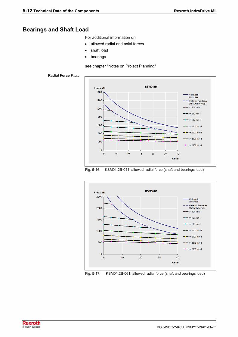
5-12 Technical Data of the Components Rexroth IndraDrive Mi
DOK-INDRV*-KCU+KSM****-PR01-EN-P
Bearings and Shaft LoadFor additional information on• allowed radial and axial forces• shaft load• bearings
see chapter "Notes on Project Planning"
Fig. 5-16: KSM01.2B-041: allowed radial force (shaft and bearings load)
Fig. 5-17: KSM01.2B-061: allowed radial force (shaft and bearings load)
Radial Force Fradial
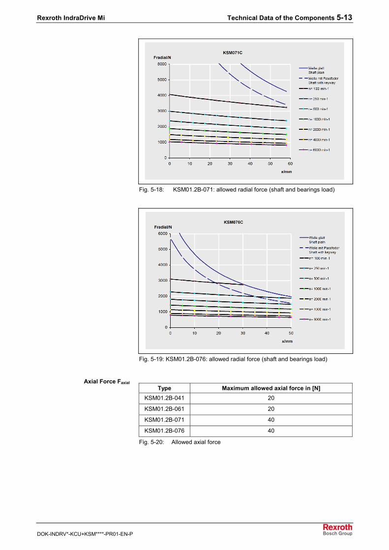
Rexroth IndraDrive Mi Technical Data of the Components 5-13
DOK-INDRV*-KCU+KSM****-PR01-EN-P
Fig. 5-18: KSM01.2B-071: allowed radial force (shaft and bearings load)
Fig. 5-19: KSM01.2B-076: allowed radial force (shaft and bearings load)
Type Maximum allowed axial force in [N]KSM01.2B-041 20
KSM01.2B-061 20
KSM01.2B-071 40
KSM01.2B-076 40
Fig. 5-20: Allowed axial force
Axial Force Faxial
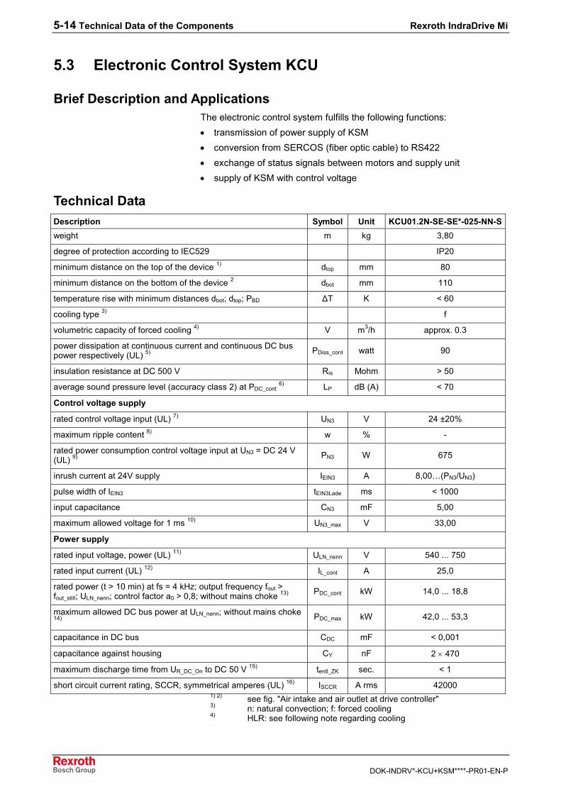
5-14 Technical Data of the Components Rexroth IndraDrive Mi
DOK-INDRV*-KCU+KSM****-PR01-EN-P
5.3 Electronic Control System KCU
Brief Description and ApplicationsThe electronic control system fulfills the following functions:• transmission of power supply of KSM• conversion from SERCOS (fiber optic cable) to RS422• exchange of status signals between motors and supply unit• supply of KSM with control voltage
Technical DataDescription Symbol Unit KCU01.2N-SE-SE*-025-NN-Sweight m kg 3,80
degree of protection according to IEC529 IP20
minimum distance on the top of the device 1) dtop mm 80
minimum distance on the bottom of the device 2 dbot mm 110
temperature rise with minimum distances dbot; dtop; PBD ∆T K < 60
cooling type 3) f
volumetric capacity of forced cooling 4) V m3/h approx. 0.3
power dissipation at continuous current and continuous DC buspower respectively (UL) 5) PDiss_cont watt 90
insulation resistance at DC 500 V Ris Mohm > 50
average sound pressure level (accuracy class 2) at PDC_cont 6) LP dB (A) < 70
Control voltage supply
rated control voltage input (UL) 7) UN3 V 24 ±20%
maximum ripple content 8) w % -
rated power consumption control voltage input at UN3 = DC 24 V(UL) 9) PN3 W 675
inrush current at 24V supply IEIN3 A 8,00…(PN3/UN3)
pulse width of IEIN3 tEIN3Lade ms < 1000
input capacitance CN3 mF 5,00
maximum allowed voltage for 1 ms 10) UN3_max V 33,00
Power supply
rated input voltage, power (UL) 11) ULN_nenn V 540 ... 750
rated input current (UL) 12) IL_cont A 25,0
rated power (t > 10 min) at fs = 4 kHz; output frequency fout >fout_still; ULN_nenn; control factor a0 > 0,8; without mains choke 13) PDC_cont kW 14,0 ... 18,8
maximum allowed DC bus power at ULN_nenn; without mains choke14) PDC_max kW 42,0 ... 53,3
capacitance in DC bus CDC mF < 0,001
capacitance against housing CY nF 2 × 470
maximum discharge time from UR_DC_On to DC 50 V 15) tentl_ZK sec. < 1
short circuit current rating, SCCR, symmetrical amperes (UL) 16) ISCCR A rms 420001) 2) see fig. "Air intake and air outlet at drive controller"3) n: natural convection; f: forced cooling4) HLR: see following note regarding cooling
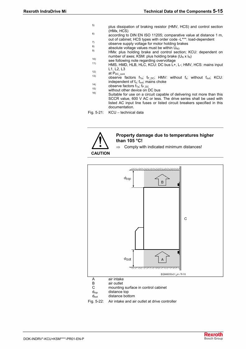
Rexroth IndraDrive Mi Technical Data of the Components 5-15
DOK-INDRV*-KCU+KSM****-PR01-EN-P
5) plus dissipation of braking resistor (HMV, HCS) and control section(HMx, HCS)
6) according to DIN EN ISO 11205; comparative value at distance 1 m,out of cabinet; HCS types with order code -L***: load-dependent
7) observe supply voltage for motor holding brakes8) absolute voltage values must be within UN39) HMx: plus holding brake and control section; KCU: dependent on
number of axes; KSM: plus holding brake (UN x IN)10) see following note regarding overvoltage11) HMS, HMD, HLB, HLC, KCU: DC bus L+, L-; HMV, HCS: mains input
L1, L2, L312) at PDC_cont13) observe factors fTa; fP_DC; HMV: without fs; without fout; KCU:
independent of fs; fout; mains choke14) observe factors fTa; fP_DC15) without other device on DC bus16) Suitable for use on a circuit capable of delivering not more than this
SCCR value, 600 V AC or less. The drive series shall be used withlisted AC input line fuses or listed circuit breakers specified in thisdocumentation.
Fig. 5-21: KCU – technical data
CAUTION
Property damage due to temperatures higherthan 105 °C!⇒ Comply with indicated minimum distances!
A air intakeB air outletC mounting surface in control cabinetdtop distance topdbot distance bottom
Fig. 5-22: Air intake and air outlet at drive controller
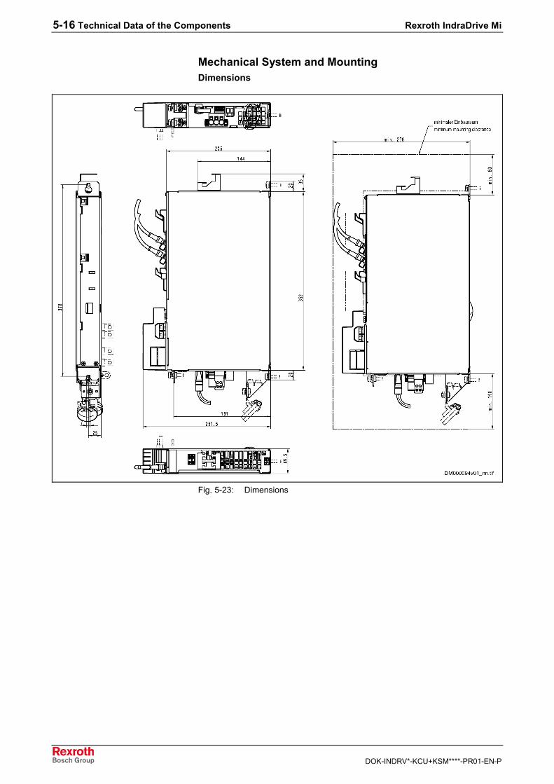
5-16 Technical Data of the Components Rexroth IndraDrive Mi
DOK-INDRV*-KCU+KSM****-PR01-EN-P
Mechanical System and MountingDimensions
Fig. 5-23: Dimensions
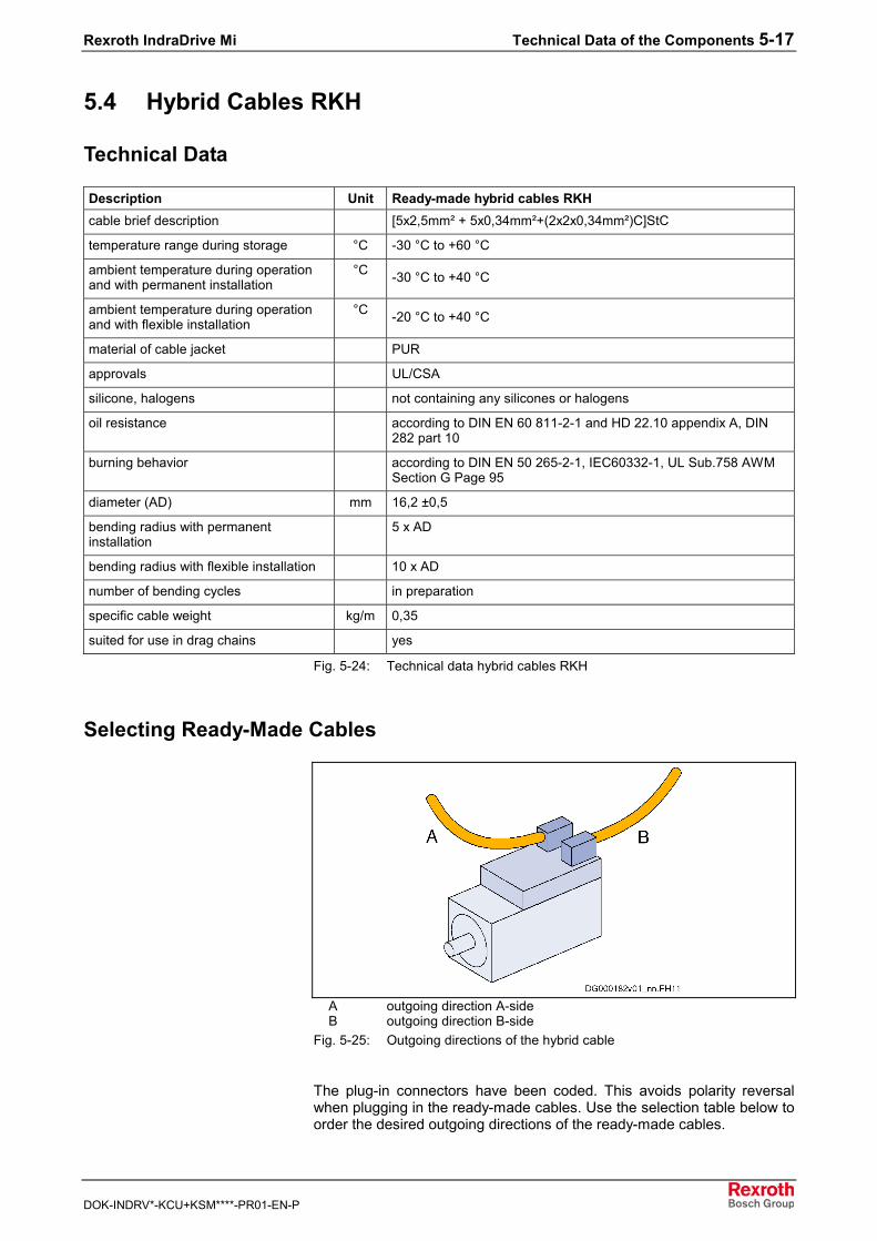
Rexroth IndraDrive Mi Technical Data of the Components 5-17
DOK-INDRV*-KCU+KSM****-PR01-EN-P
5.4 Hybrid Cables RKH
Technical Data
Description Unit Ready-made hybrid cables RKHcable brief description [5x2,5mm² + 5x0,34mm²+(2x2x0,34mm²)C]StC
temperature range during storage °C -30 °C to +60 °C
ambient temperature during operationand with permanent installation
°C -30 °C to +40 °C
ambient temperature during operationand with flexible installation
°C -20 °C to +40 °C
material of cable jacket PUR
approvals UL/CSA
silicone, halogens not containing any silicones or halogens
oil resistance according to DIN EN 60 811-2-1 and HD 22.10 appendix A, DIN282 part 10
burning behavior according to DIN EN 50 265-2-1, IEC60332-1, UL Sub.758 AWMSection G Page 95
diameter (AD) mm 16,2 ±0,5
bending radius with permanentinstallation
5 x AD
bending radius with flexible installation 10 x AD
number of bending cycles in preparation
specific cable weight kg/m 0,35
suited for use in drag chains yes
Fig. 5-24: Technical data hybrid cables RKH
Selecting Ready-Made Cables
A outgoing direction A-sideB outgoing direction B-side
Fig. 5-25: Outgoing directions of the hybrid cable
The plug-in connectors have been coded. This avoids polarity reversalwhen plugging in the ready-made cables. Use the selection table below toorder the desired outgoing directions of the ready-made cables.
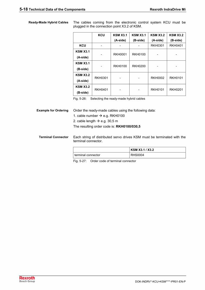
5-18 Technical Data of the Components Rexroth IndraDrive Mi
DOK-INDRV*-KCU+KSM****-PR01-EN-P
The cables coming from the electronic control system KCU must beplugged in the connection point X3.2 of KSM.
KCU KSM X3.1(A-side)
KSM X3.1(B-side)
KSM X3.2(A-side)
KSM X3.2(B-side)
KCU - - - RKH0301 RKH0401
KSM X3.1
(A-side)- RKH0001 RKH0100 - -
KSM X3.1
(B-side)- RKH0100 RKH0200 - -
KSM X3.2
(A-side)RKH0301 - - RKH0002 RKH0101
KSM X3.2
(B-side)RKH0401 - - RKH0101 RKH0201
Fig. 5-26: Selecting the ready-made hybrid cables
Order the ready-made cables using the following data:1. cable number e.g. RKH01002. cable length e.g. 30,5 mThe resulting order code is: RKH0100/030,5
Each string of distributed servo drives KSM must be terminated with theterminal connector.
KSM X3.1 / X3.2terminal connector RHS0004
Fig. 5-27: Order code of terminal connector
Ready-Made Hybrid Cables
Example for Ordering
Terminal Connector
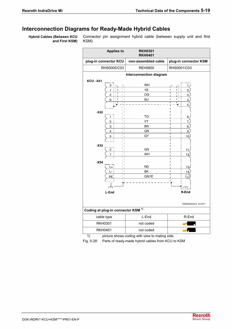
Rexroth IndraDrive Mi Technical Data of the Components 5-19
DOK-INDRV*-KCU+KSM****-PR01-EN-P
Interconnection Diagrams for Ready-Made Hybrid CablesConnector pin assignment hybrid cable (between supply unit and firstKSM)
Applies to RKH0301RKH0401
plug-in connector KCU non-assembled cable plug-in connector KSM
RHS0005/C03 REH0800 RHS0001/C03
Interconnection diagram
Coding at plug-in connector KSM 1)
cable type L-End R-End
RKH0301 not coded
RKH0401 not coded
1) picture shows coding with view to mating sideFig. 5-28: Parts of ready-made hybrid cables from KCU to KSM
Hybrid Cables (Between KCUand First KSM)
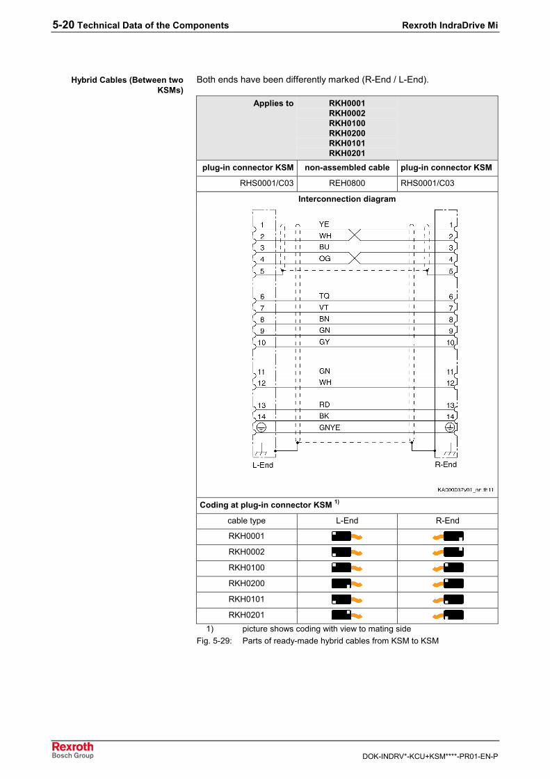
5-20 Technical Data of the Components Rexroth IndraDrive Mi
DOK-INDRV*-KCU+KSM****-PR01-EN-P
Both ends have been differently marked (R-End / L-End).
Applies to RKH0001RKH0002RKH0100RKH0200RKH0101RKH0201
plug-in connector KSM non-assembled cable plug-in connector KSM
RHS0001/C03 REH0800 RHS0001/C03
Interconnection diagram
Coding at plug-in connector KSM 1)
cable type L-End R-End
RKH0001
RKH0002
RKH0100
RKH0200
RKH0101
RKH0201
1) picture shows coding with view to mating sideFig. 5-29: Parts of ready-made hybrid cables from KSM to KSM
Hybrid Cables (Between twoKSMs)
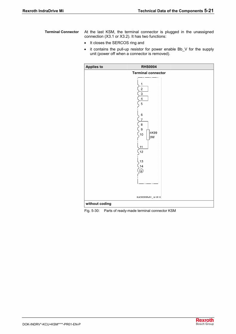
Rexroth IndraDrive Mi Technical Data of the Components 5-21
DOK-INDRV*-KCU+KSM****-PR01-EN-P
At the last KSM, the terminal connector is plugged in the unassignedconnection (X3.1 or X3.2). It has two functions:• It closes the SERCOS ring and• it contains the pull-up resistor for power enable Bb_V for the supply
unit (power off when a connector is removed).
Applies to RHS0004Terminal connector
without coding
Fig. 5-30: Parts of ready-made terminal connector KSM
Terminal Connector

5-22 Technical Data of the Components Rexroth IndraDrive Mi
DOK-INDRV*-KCU+KSM****-PR01-EN-P
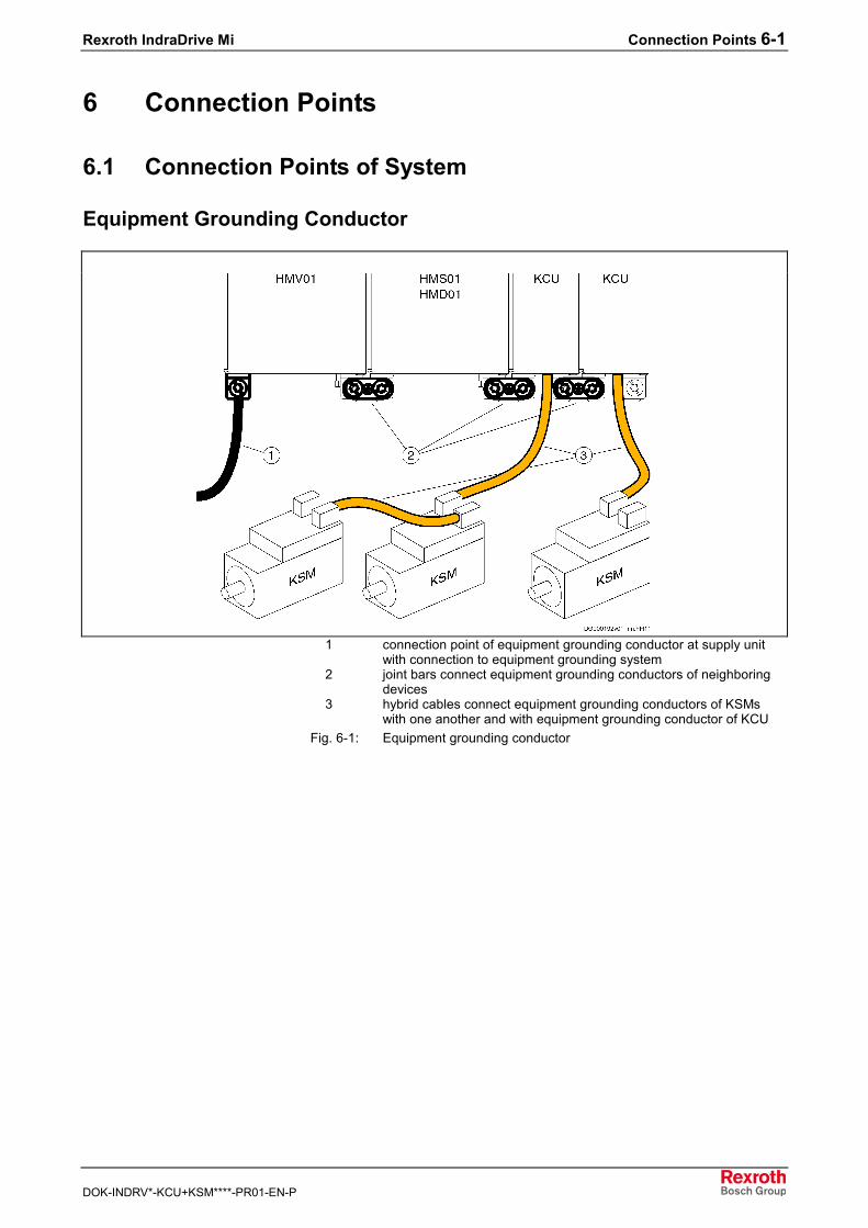
Rexroth IndraDrive Mi Connection Points 6-1
DOK-INDRV*-KCU+KSM****-PR01-EN-P
6 Connection Points
6.1 Connection Points of System
Equipment Grounding Conductor
1 connection point of equipment grounding conductor at supply unitwith connection to equipment grounding system
2 joint bars connect equipment grounding conductors of neighboringdevices
3 hybrid cables connect equipment grounding conductors of KSMswith one another and with equipment grounding conductor of KCU
Fig. 6-1: Equipment grounding conductor
6-2 Connection Points Rexroth IndraDrive Mi
DOK-INDRV*-KCU+KSM****-PR01-EN-P
Ground Connection
CAUTION
Damage to the devices by voltage arcing!⇒ For applications which can produce high static
charging (e.g. printing, packaging), the impedancefrom the connection point of the machine to the drivesystem must not be more than 8 ohm (e.g.measured from fixing points of motor flanges toground connection of electronic control systemKCU).
⇒ An isolating transformer (UK ≤ 2.5%) must beinstalled for mains types unequal TN-C.
The ground connection of the housing is used to provide functional safetyof the devices and protection against contact in conjunction with theequipment grounding conductor.
Ground the housings of the devices:1. Connect the bare metal back panel of the devices in conductive form
to the mounting surface in the control cabinet. To do this, use thesupplied mounting screws.
2. Connect the mounting surface of the control cabinet in conductiveform to the equipment grounding system.
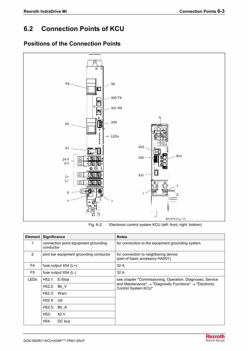
Rexroth IndraDrive Mi Connection Points 6-3
DOK-INDRV*-KCU+KSM****-PR01-EN-P
6.2 Connection Points of KCU
Positions of the Connection Points
Fig. 6-2: Electronic control system KCU (left: front, right: bottom)
Element Significance Notes1 connection point equipment grounding
conductorfor connection to the equipment grounding system
2 joint bar equipment grounding conductor for connection to neighboring device(part of basic accessory HAS01)
F4 fuse output X54 (L+) 32 A
F5 fuse output X54 (L-) 32 A
H52.1: E-Stop
H52.2: Bb_V
H52.3: Warn
H52.4: Ud
H52.5: Bb_A
H53: 42 V
LEDs
H54: DC bus
see chapter "Commissioning, Operation, Diagnoses, Serviceand Maintenance" → "Diagnostic Functions" → "ElectronicControl System KCU"
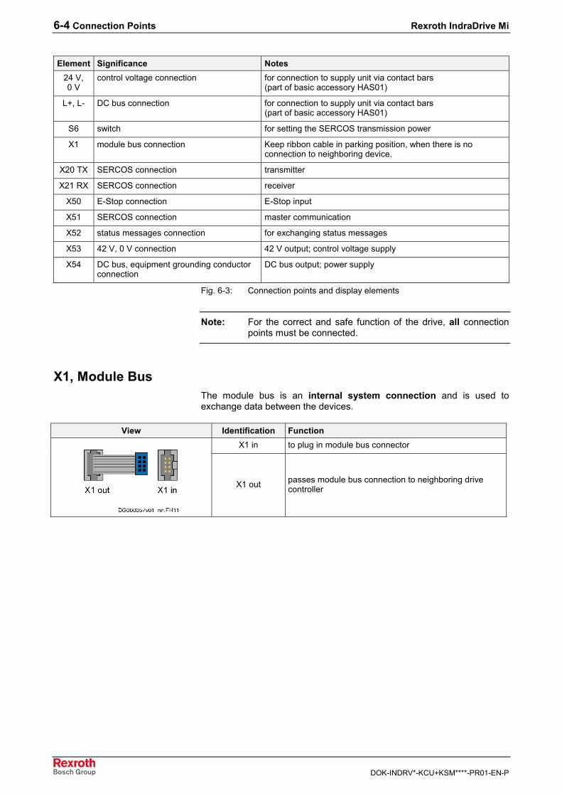
6-4 Connection Points Rexroth IndraDrive Mi
DOK-INDRV*-KCU+KSM****-PR01-EN-P
Element Significance Notes24 V,0 V
control voltage connection for connection to supply unit via contact bars(part of basic accessory HAS01)
L+, L- DC bus connection for connection to supply unit via contact bars(part of basic accessory HAS01)
S6 switch for setting the SERCOS transmission power
X1 module bus connection Keep ribbon cable in parking position, when there is noconnection to neighboring device.
X20 TX SERCOS connection transmitter
X21 RX SERCOS connection receiver
X50 E-Stop connection E-Stop input
X51 SERCOS connection master communication
X52 status messages connection for exchanging status messages
X53 42 V, 0 V connection 42 V output; control voltage supply
X54 DC bus, equipment grounding conductorconnection
DC bus output; power supply
Fig. 6-3: Connection points and display elements
Note: For the correct and safe function of the drive, all connectionpoints must be connected.
X1, Module BusThe module bus is an internal system connection and is used toexchange data between the devices.
View Identification FunctionX1 in to plug in module bus connector
X1 out passes module bus connection to neighboring drivecontroller
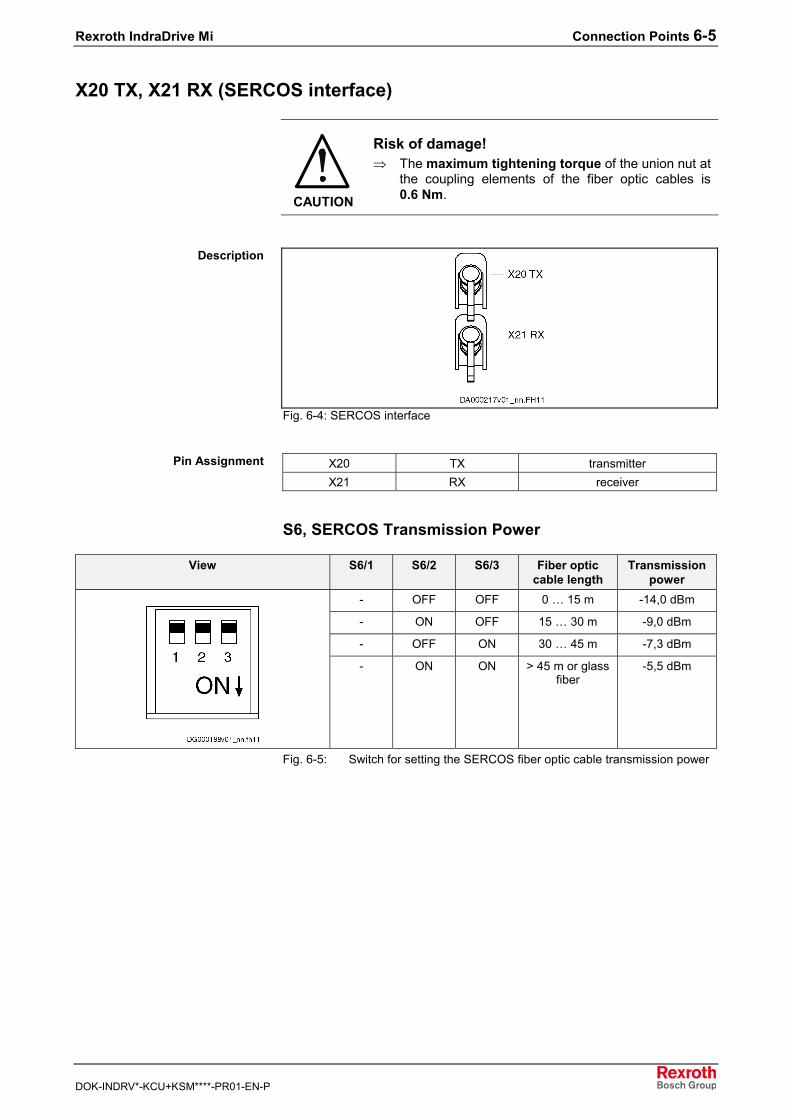
Rexroth IndraDrive Mi Connection Points 6-5
DOK-INDRV*-KCU+KSM****-PR01-EN-P
X20 TX, X21 RX (SERCOS interface)
CAUTION
Risk of damage!⇒ The maximum tightening torque of the union nut at
the coupling elements of the fiber optic cables is0.6 Nm.
Fig. 6-4: SERCOS interface
X20 TX transmitterX21 RX receiver
S6, SERCOS Transmission Power
View S6/1 S6/2 S6/3 Fiber opticcable length
Transmissionpower
- OFF OFF 0 … 15 m -14,0 dBm
- ON OFF 15 … 30 m -9,0 dBm
- OFF ON 30 … 45 m -7,3 dBm
- ON ON > 45 m or glassfiber
-5,5 dBm
Fig. 6-5: Switch for setting the SERCOS fiber optic cable transmission power
Description
Pin Assignment
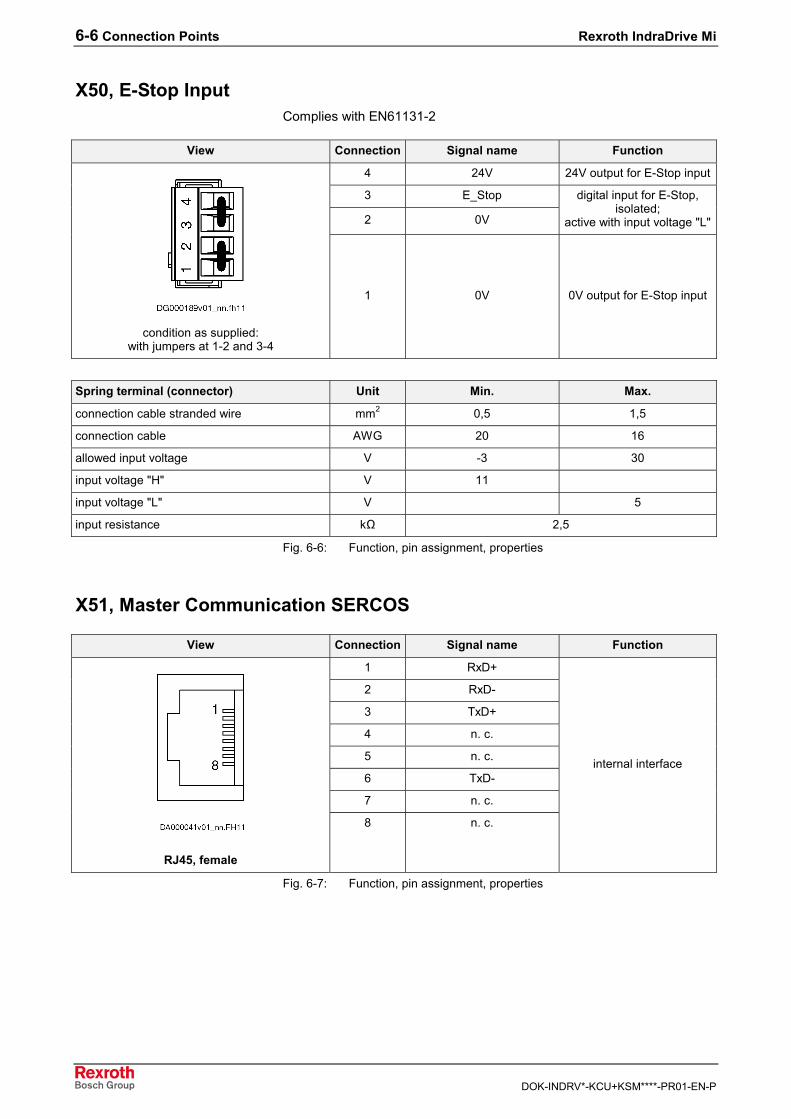
6-6 Connection Points Rexroth IndraDrive Mi
DOK-INDRV*-KCU+KSM****-PR01-EN-P
X50, E-Stop InputComplies with EN61131-2
View Connection Signal name Function
4 24V 24V output for E-Stop input
3 E_Stop
2 0V
digital input for E-Stop,isolated;
active with input voltage "L"
condition as supplied:with jumpers at 1-2 and 3-4
1 0V 0V output for E-Stop input
Spring terminal (connector) Unit Min. Max.
connection cable stranded wire mm2 0,5 1,5
connection cable AWG 20 16
allowed input voltage V -3 30
input voltage "H" V 11
input voltage "L" V 5
input resistance kΩ 2,5
Fig. 6-6: Function, pin assignment, properties
X51, Master Communication SERCOS
View Connection Signal name Function
1 RxD+
2 RxD-
3 TxD+
4 n. c.
5 n. c.
6 TxD-
7 n. c.
RJ45, female
8 n. c.
internal interface
Fig. 6-7: Function, pin assignment, properties
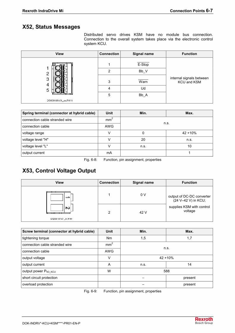
Rexroth IndraDrive Mi Connection Points 6-7
DOK-INDRV*-KCU+KSM****-PR01-EN-P
X52, Status MessagesDistributed servo drives KSM have no module bus connection.Connection to the overall system takes place via the electronic controlsystem KCU.
View Connection Signal name Function
1______E-Stop
2 Bb_V
3_____Warn
4 Ud
5 Bb_A
internal signals betweenKCU and KSM
Spring terminal (connector at hybrid cable) Unit Min. Max.
connection cable stranded wire mm2
connection cable AWGn.s.
voltage range V 0 42 +10%
voltage level "H" V 20 n.s.
voltage level "L" V n.s. 10
output current mA 1
Fig. 6-8: Function, pin assignment, properties
X53, Control Voltage Output
View Connection Signal name Function
1 0 V
2 42 V
output of DC-DC converter(24 V–42 V) in KCU;
supplies KSM with controlvoltage
Screw terminal (connector at hybrid cable) Unit Min. Max.
tightening torque Nm 1,5 1,7
connection cable stranded wire mm2
connection cable AWGn.s.
output voltage V 42 +10%
output current A n.s. 14
output power PN3_KCU W 588
short circuit protection – present
overload protection – present
Fig. 6-9: Function, pin assignment, properties
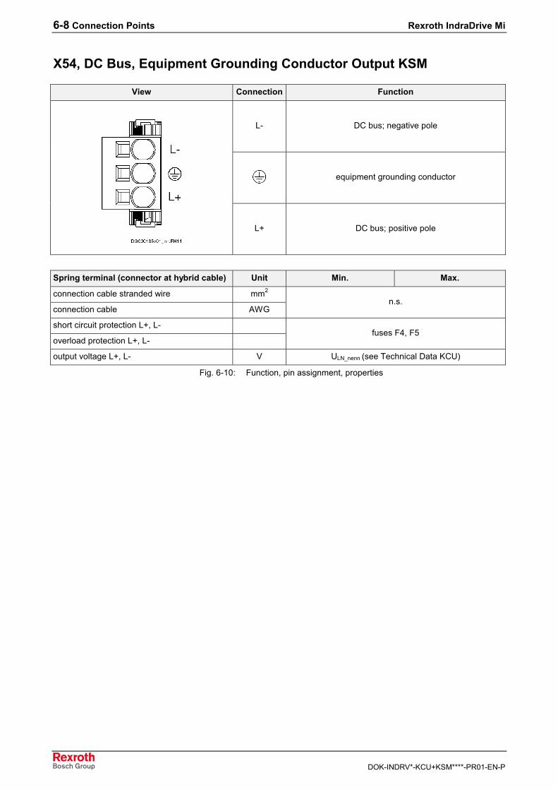
6-8 Connection Points Rexroth IndraDrive Mi
DOK-INDRV*-KCU+KSM****-PR01-EN-P
X54, DC Bus, Equipment Grounding Conductor Output KSM
View Connection Function
L- DC bus; negative pole
equipment grounding conductor
L+ DC bus; positive pole
Spring terminal (connector at hybrid cable) Unit Min. Max.
connection cable stranded wire mm2
connection cable AWGn.s.
short circuit protection L+, L-
overload protection L+, L-fuses F4, F5
output voltage L+, L- V ULN_nenn (see Technical Data KCU)
Fig. 6-10: Function, pin assignment, properties
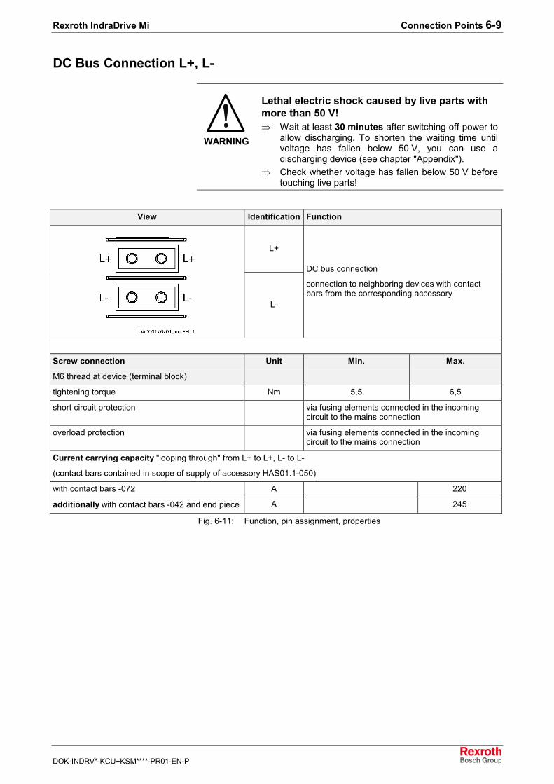
Rexroth IndraDrive Mi Connection Points 6-9
DOK-INDRV*-KCU+KSM****-PR01-EN-P
DC Bus Connection L+, L-
WARNING
Lethal electric shock caused by live parts withmore than 50 V!⇒ Wait at least 30 minutes after switching off power to
allow discharging. To shorten the waiting time untilvoltage has fallen below 50 V, you can use adischarging device (see chapter "Appendix").
⇒ Check whether voltage has fallen below 50 V beforetouching live parts!
View Identification Function
L+
L-
DC bus connection
connection to neighboring devices with contactbars from the corresponding accessory
Screw connection
M6 thread at device (terminal block)
Unit Min. Max.
tightening torque Nm 5,5 6,5
short circuit protection via fusing elements connected in the incomingcircuit to the mains connection
overload protection via fusing elements connected in the incomingcircuit to the mains connection
Current carrying capacity "looping through" from L+ to L+, L- to L-
(contact bars contained in scope of supply of accessory HAS01.1-050)
with contact bars -072 A 220
additionally with contact bars -042 and end piece A 245
Fig. 6-11: Function, pin assignment, properties
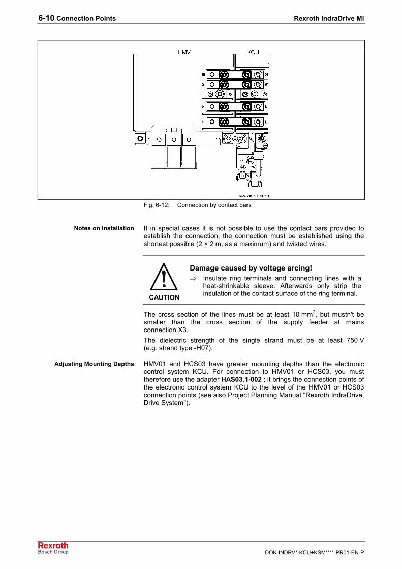
6-10 Connection Points Rexroth IndraDrive Mi
DOK-INDRV*-KCU+KSM****-PR01-EN-P
Fig. 6-12: Connection by contact bars
If in special cases it is not possible to use the contact bars provided toestablish the connection, the connection must be established using theshortest possible (2 × 2 m, as a maximum) and twisted wires.
CAUTION
Damage caused by voltage arcing!⇒ Insulate ring terminals and connecting lines with a
heat-shrinkable sleeve. Afterwards only strip theinsulation of the contact surface of the ring terminal.
The cross section of the lines must be at least 10 mm2, but mustn't besmaller than the cross section of the supply feeder at mainsconnection X3.The dielectric strength of the single strand must be at least 750 V(e.g. strand type -H07).
HMV01 and HCS03 have greater mounting depths than the electroniccontrol system KCU. For connection to HMV01 or HCS03, you musttherefore use the adapter HAS03.1-002 ; it brings the connection points ofthe electronic control system KCU to the level of the HMV01 or HCS03connection points (see also Project Planning Manual "Rexroth IndraDrive,Drive System").
Notes on Installation
Adjusting Mounting Depths
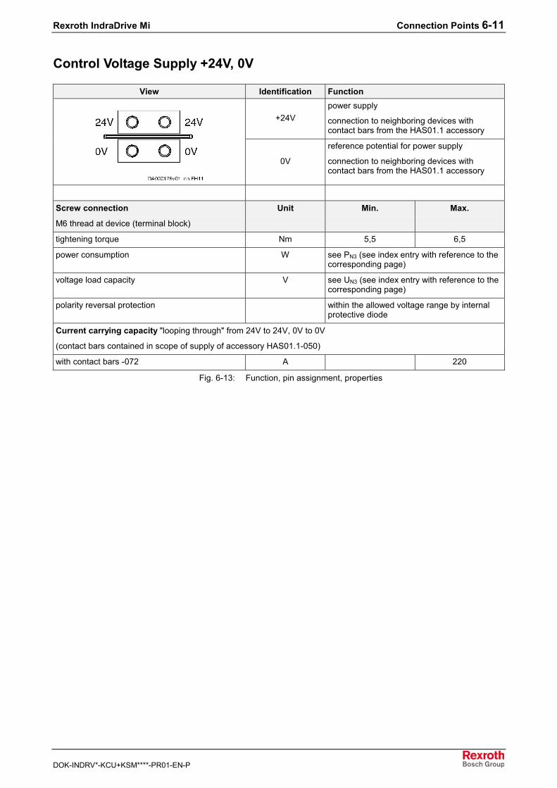
Rexroth IndraDrive Mi Connection Points 6-11
DOK-INDRV*-KCU+KSM****-PR01-EN-P
Control Voltage Supply +24V, 0V
View Identification Function
+24Vpower supply
connection to neighboring devices withcontact bars from the HAS01.1 accessory
0V
reference potential for power supply
connection to neighboring devices withcontact bars from the HAS01.1 accessory
Screw connection
M6 thread at device (terminal block)
Unit Min. Max.
tightening torque Nm 5,5 6,5
power consumption W see PN3 (see index entry with reference to thecorresponding page)
voltage load capacity V see UN3 (see index entry with reference to thecorresponding page)
polarity reversal protection within the allowed voltage range by internalprotective diode
Current carrying capacity "looping through" from 24V to 24V, 0V to 0V
(contact bars contained in scope of supply of accessory HAS01.1-050)
with contact bars -072 A 220
Fig. 6-13: Function, pin assignment, properties
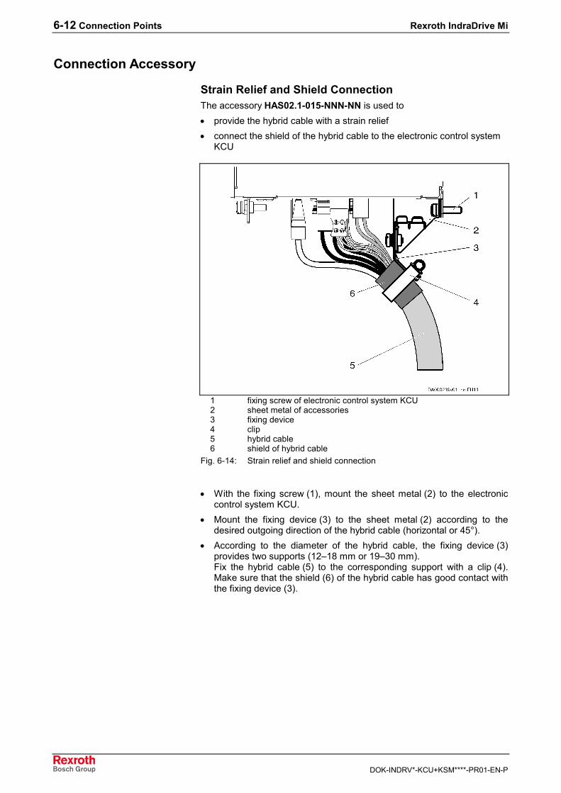
6-12 Connection Points Rexroth IndraDrive Mi
DOK-INDRV*-KCU+KSM****-PR01-EN-P
Connection Accessory
Strain Relief and Shield ConnectionThe accessory HAS02.1-015-NNN-NN is used to• provide the hybrid cable with a strain relief• connect the shield of the hybrid cable to the electronic control system
KCU
1 fixing screw of electronic control system KCU2 sheet metal of accessories3 fixing device4 clip5 hybrid cable6 shield of hybrid cable
Fig. 6-14: Strain relief and shield connection
• With the fixing screw (1), mount the sheet metal (2) to the electroniccontrol system KCU.
• Mount the fixing device (3) to the sheet metal (2) according to thedesired outgoing direction of the hybrid cable (horizontal or 45°).
• According to the diameter of the hybrid cable, the fixing device (3)provides two supports (12–18 mm or 19–30 mm).Fix the hybrid cable (5) to the corresponding support with a clip (4).Make sure that the shield (6) of the hybrid cable has good contact withthe fixing device (3).
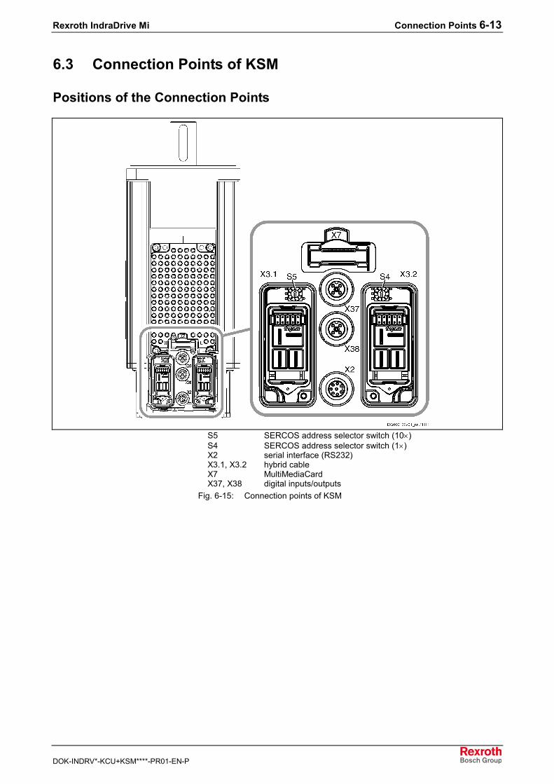
Rexroth IndraDrive Mi Connection Points 6-13
DOK-INDRV*-KCU+KSM****-PR01-EN-P
6.3 Connection Points of KSM
Positions of the Connection Points
S5 SERCOS address selector switch (10×)S4 SERCOS address selector switch (1×)X2 serial interface (RS232)X3.1, X3.2 hybrid cableX7 MultiMediaCardX37, X38 digital inputs/outputs
Fig. 6-15: Connection points of KSM
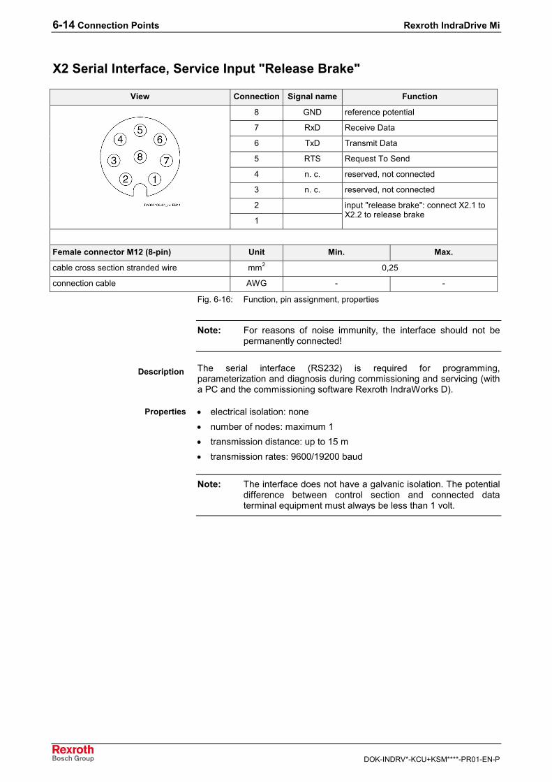
6-14 Connection Points Rexroth IndraDrive Mi
DOK-INDRV*-KCU+KSM****-PR01-EN-P
X2 Serial Interface, Service Input "Release Brake"
View Connection Signal name Function
8 GND reference potential
7 RxD Receive Data
6 TxD Transmit Data
5 RTS Request To Send
4 n. c. reserved, not connected
3 n. c. reserved, not connected
2
1
input "release brake": connect X2.1 toX2.2 to release brake
Female connector M12 (8-pin) Unit Min. Max.
cable cross section stranded wire mm2 0,25
connection cable AWG - -
Fig. 6-16: Function, pin assignment, properties
Note: For reasons of noise immunity, the interface should not bepermanently connected!
The serial interface (RS232) is required for programming,parameterization and diagnosis during commissioning and servicing (witha PC and the commissioning software Rexroth IndraWorks D).
• electrical isolation: none• number of nodes: maximum 1• transmission distance: up to 15 m• transmission rates: 9600/19200 baud
Note: The interface does not have a galvanic isolation. The potentialdifference between control section and connected dataterminal equipment must always be less than 1 volt.
Description
Properties
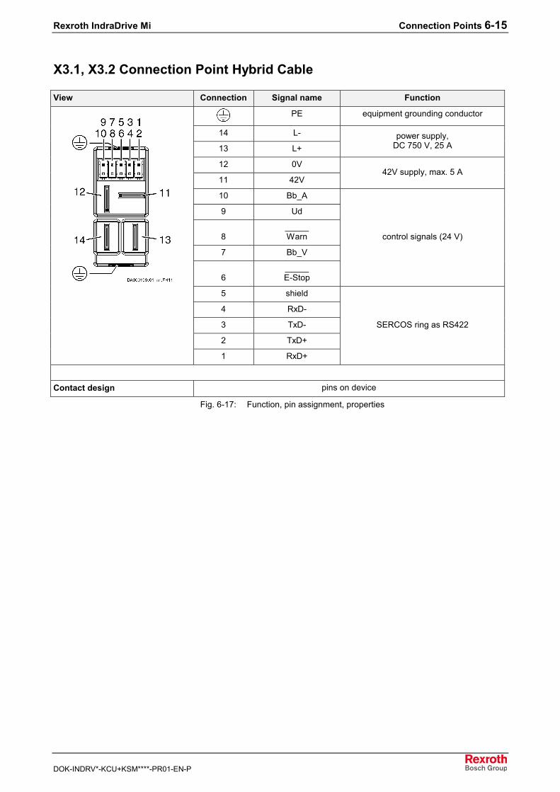
Rexroth IndraDrive Mi Connection Points 6-15
DOK-INDRV*-KCU+KSM****-PR01-EN-P
X3.1, X3.2 Connection Point Hybrid Cable
View Connection Signal name Function
PE equipment grounding conductor
14 L-
13 L+power supply,
DC 750 V, 25 A
12 0V
11 42V42V supply, max. 5 A
10 Bb_A
9 Ud
8_____Warn
7 Bb_V
6_____E-Stop
control signals (24 V)
5 shield
4 RxD-
3 TxD-
2 TxD+
1 RxD+
SERCOS ring as RS422
Contact design pins on device
Fig. 6-17: Function, pin assignment, properties
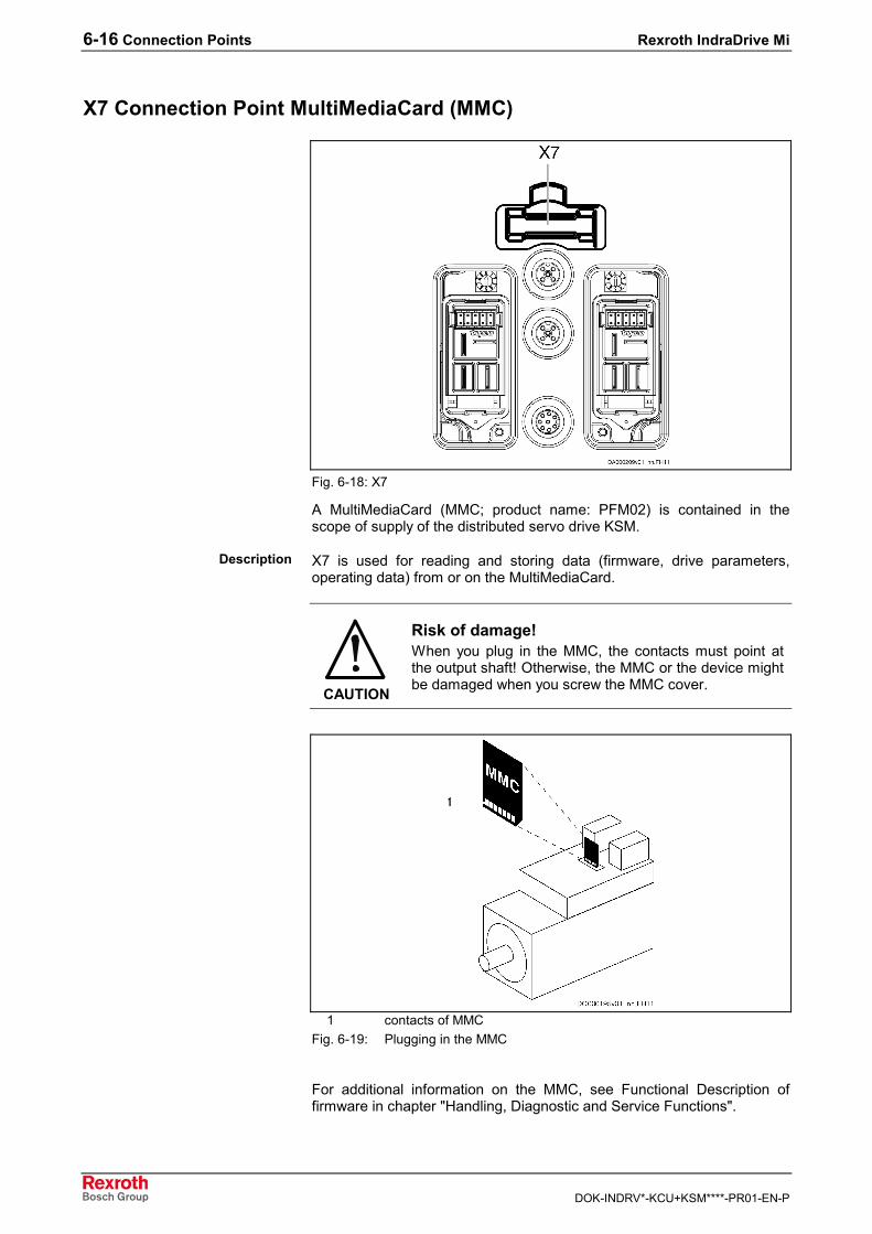
6-16 Connection Points Rexroth IndraDrive Mi
DOK-INDRV*-KCU+KSM****-PR01-EN-P
X7 Connection Point MultiMediaCard (MMC)
Fig. 6-18: X7
A MultiMediaCard (MMC; product name: PFM02) is contained in thescope of supply of the distributed servo drive KSM.
X7 is used for reading and storing data (firmware, drive parameters,operating data) from or on the MultiMediaCard.
CAUTION
Risk of damage!When you plug in the MMC, the contacts must point atthe output shaft! Otherwise, the MMC or the device mightbe damaged when you screw the MMC cover.
1 contacts of MMCFig. 6-19: Plugging in the MMC
For additional information on the MMC, see Functional Description offirmware in chapter "Handling, Diagnostic and Service Functions".
Description
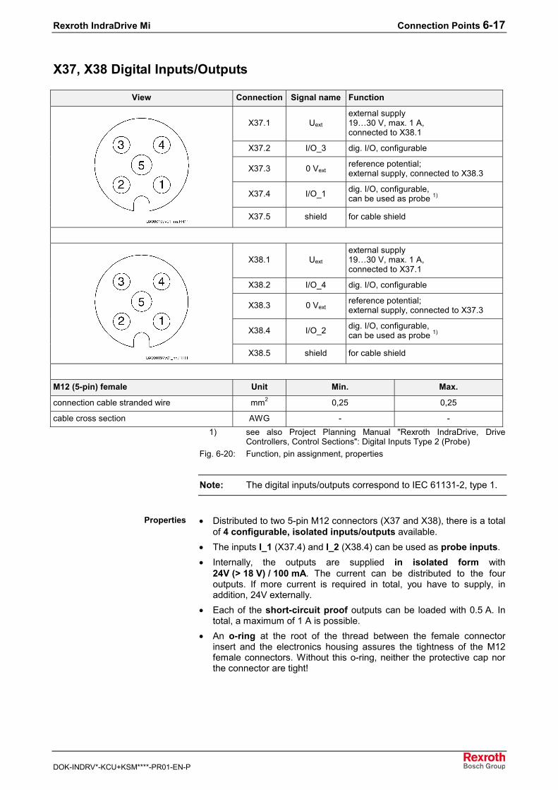
Rexroth IndraDrive Mi Connection Points 6-17
DOK-INDRV*-KCU+KSM****-PR01-EN-P
X37, X38 Digital Inputs/Outputs
View Connection Signal name Function
X37.1 Uext
external supply19…30 V, max. 1 A,connected to X38.1
X37.2 I/O_3 dig. I/O, configurable
X37.3 0 Vextreference potential;external supply, connected to X38.3
X37.4 I/O_1 dig. I/O, configurable,can be used as probe 1)
X37.5 shield for cable shield
X38.1 Uext
external supply19…30 V, max. 1 A,connected to X37.1
X38.2 I/O_4 dig. I/O, configurable
X38.3 0 Vextreference potential;external supply, connected to X37.3
X38.4 I/O_2 dig. I/O, configurable,can be used as probe 1)
X38.5 shield for cable shield
M12 (5-pin) female Unit Min. Max.
connection cable stranded wire mm2 0,25 0,25
cable cross section AWG - -1) see also Project Planning Manual "Rexroth IndraDrive, Drive
Controllers, Control Sections": Digital Inputs Type 2 (Probe)Fig. 6-20: Function, pin assignment, properties
Note: The digital inputs/outputs correspond to IEC 61131-2, type 1.
• Distributed to two 5-pin M12 connectors (X37 and X38), there is a totalof 4 configurable, isolated inputs/outputs available.
• The inputs I_1 (X37.4) and I_2 (X38.4) can be used as probe inputs.• Internally, the outputs are supplied in isolated form with
24V (> 18 V) / 100 mA. The current can be distributed to the fouroutputs. If more current is required in total, you have to supply, inaddition, 24V externally.
• Each of the short-circuit proof outputs can be loaded with 0.5 A. Intotal, a maximum of 1 A is possible.
• An o-ring at the root of the thread between the female connectorinsert and the electronics housing assures the tightness of the M12female connectors. Without this o-ring, neither the protective cap northe connector are tight!
Properties

6-18 Connection Points Rexroth IndraDrive Mi
DOK-INDRV*-KCU+KSM****-PR01-EN-P
Data Unit Min. Typ. Max.allowed input voltage V -3 30
On V 15
Off V 5
input current mA 2 5
input resistance kΩ non-linear, varies depending on inputvoltage
sampling frequency kHz depending on firmware
control delay µs 20 100 +1 cycletime ofpositioncontrol
pulse width tPuls (probe) µs 4
measuring accuracy tx(probe)
µs 1
Fig. 6-21: Digital inputs
A signalB signal detection at probe inputtPuls pulse widthtx measuring accuracy
Fig. 6-22: Signal detection at probe input
Note: Probe inputs are "rapid" inputs. For control use bounce-freeswitching elements (e.g. electronic switches) to avoid incorrectevaluation.
Data: Inputs
Probe Input
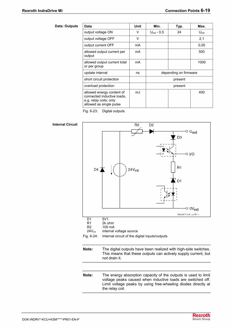
Rexroth IndraDrive Mi Connection Points 6-19
DOK-INDRV*-KCU+KSM****-PR01-EN-P
Data Unit Min. Typ. Max.output voltage ON V Uext - 0,5 24 Uext
output voltage OFF V 2,1
output current OFF mA 0,05
allowed output current peroutput
mA 500
allowed output current totalor per group
mA 1000
update interval ns depending on firmware
short circuit protection present
overload protection present
allowed energy content ofconnected inductive loads,e.g. relay coils; onlyallowed as single pulse
mJ 400
Fig. 6-23: Digital outputs
D1 5V1R1 2k ohmR2 100 mA24Vint internal voltage source
Fig. 6-24: Internal circuit of the digital inputs/outputs
Note: The digital outputs have been realized with high-side switches.This means that these outputs can actively supply current, butnot drain it.
Note: The energy absorption capacity of the outputs is used to limitvoltage peaks caused when inductive loads are switched off.Limit voltage peaks by using free-wheeling diodes directly atthe relay coil.
Data: Outputs
Internal Circuit
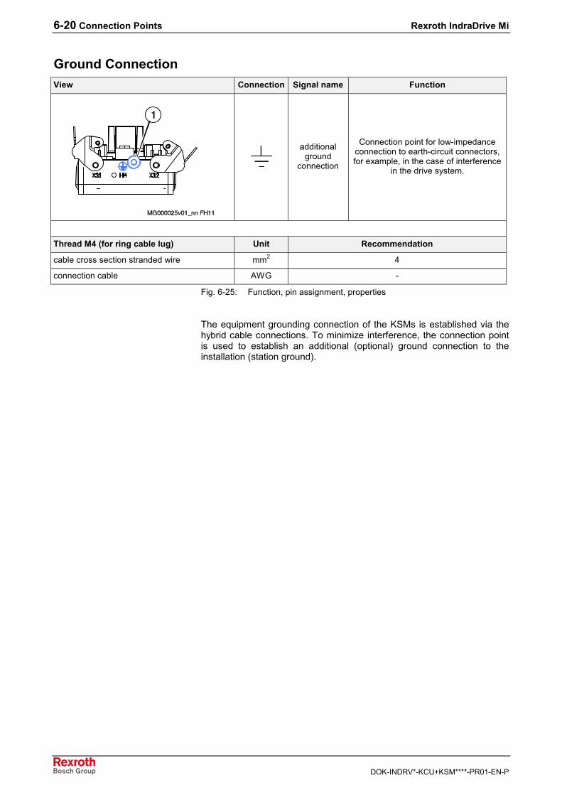
6-20 Connection Points Rexroth IndraDrive Mi
DOK-INDRV*-KCU+KSM****-PR01-EN-P
Ground ConnectionView Connection Signal name Function
additionalground
connection
Connection point for low-impedanceconnection to earth-circuit connectors,for example, in the case of interference
in the drive system.
Thread M4 (for ring cable lug) Unit Recommendation
cable cross section stranded wire mm2 4
connection cable AWG -
Fig. 6-25: Function, pin assignment, properties
The equipment grounding connection of the KSMs is established via thehybrid cable connections. To minimize interference, the connection pointis used to establish an additional (optional) ground connection to theinstallation (station ground).
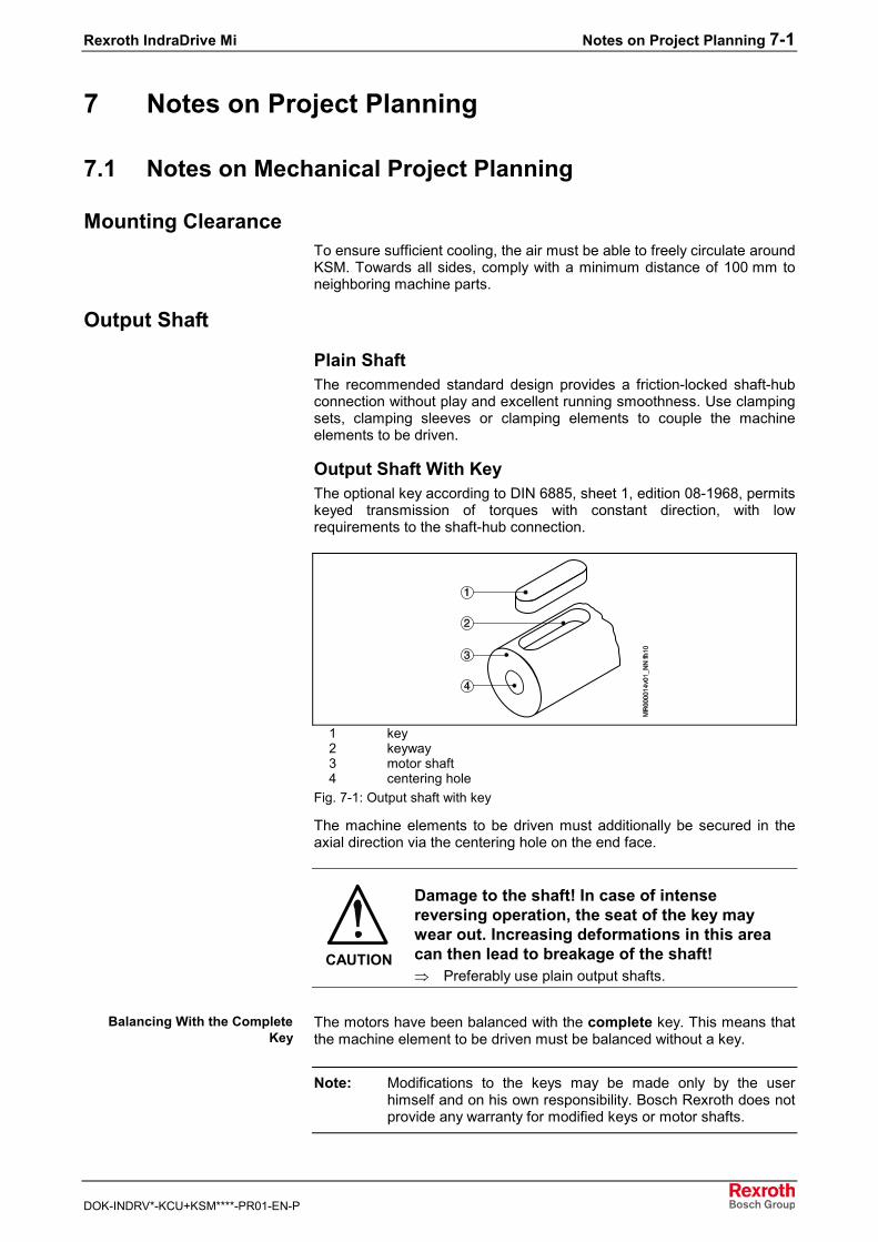
Rexroth IndraDrive Mi Notes on Project Planning 7-1
DOK-INDRV*-KCU+KSM****-PR01-EN-P
7 Notes on Project Planning
7.1 Notes on Mechanical Project Planning
Mounting ClearanceTo ensure sufficient cooling, the air must be able to freely circulate aroundKSM. Towards all sides, comply with a minimum distance of 100 mm toneighboring machine parts.
Output Shaft
Plain ShaftThe recommended standard design provides a friction-locked shaft-hubconnection without play and excellent running smoothness. Use clampingsets, clamping sleeves or clamping elements to couple the machineelements to be driven.
Output Shaft With KeyThe optional key according to DIN 6885, sheet 1, edition 08-1968, permitskeyed transmission of torques with constant direction, with lowrequirements to the shaft-hub connection.
1 key2 keyway3 motor shaft4 centering hole
Fig. 7-1: Output shaft with key
The machine elements to be driven must additionally be secured in theaxial direction via the centering hole on the end face.
CAUTION
Damage to the shaft! In case of intensereversing operation, the seat of the key maywear out. Increasing deformations in this areacan then lead to breakage of the shaft!⇒ Preferably use plain output shafts.
The motors have been balanced with the complete key. This means thatthe machine element to be driven must be balanced without a key.
Note: Modifications to the keys may be made only by the userhimself and on his own responsibility. Bosch Rexroth does notprovide any warranty for modified keys or motor shafts.
Balancing With the CompleteKey
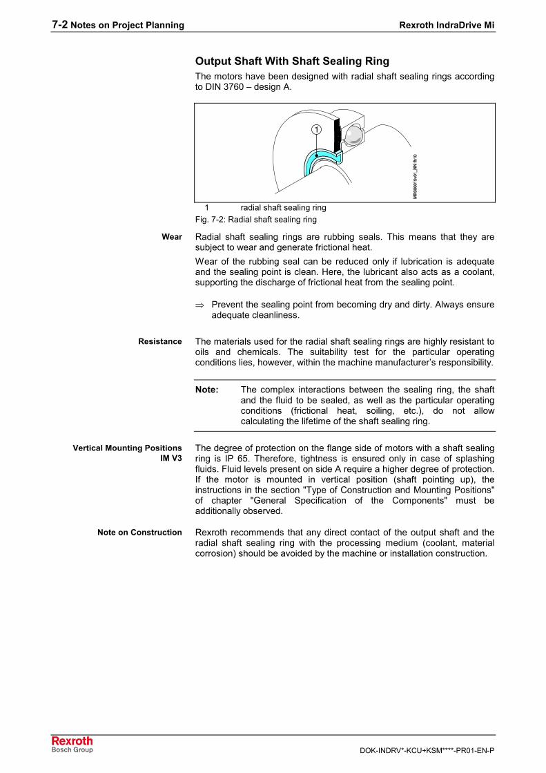
7-2 Notes on Project Planning Rexroth IndraDrive Mi
DOK-INDRV*-KCU+KSM****-PR01-EN-P
Output Shaft With Shaft Sealing RingThe motors have been designed with radial shaft sealing rings accordingto DIN 3760 – design A.
1 radial shaft sealing ringFig. 7-2: Radial shaft sealing ring
Radial shaft sealing rings are rubbing seals. This means that they aresubject to wear and generate frictional heat.Wear of the rubbing seal can be reduced only if lubrication is adequateand the sealing point is clean. Here, the lubricant also acts as a coolant,supporting the discharge of frictional heat from the sealing point.
⇒ Prevent the sealing point from becoming dry and dirty. Always ensureadequate cleanliness.
The materials used for the radial shaft sealing rings are highly resistant tooils and chemicals. The suitability test for the particular operatingconditions lies, however, within the machine manufacturer’s responsibility.
Note: The complex interactions between the sealing ring, the shaftand the fluid to be sealed, as well as the particular operatingconditions (frictional heat, soiling, etc.), do not allowcalculating the lifetime of the shaft sealing ring.
The degree of protection on the flange side of motors with a shaft sealingring is IP 65. Therefore, tightness is ensured only in case of splashingfluids. Fluid levels present on side A require a higher degree of protection.If the motor is mounted in vertical position (shaft pointing up), theinstructions in the section "Type of Construction and Mounting Positions"of chapter "General Specification of the Components" must beadditionally observed.
Rexroth recommends that any direct contact of the output shaft and theradial shaft sealing ring with the processing medium (coolant, materialcorrosion) should be avoided by the machine or installation construction.
Wear
Resistance
Vertical Mounting PositionsIM V3
Note on Construction
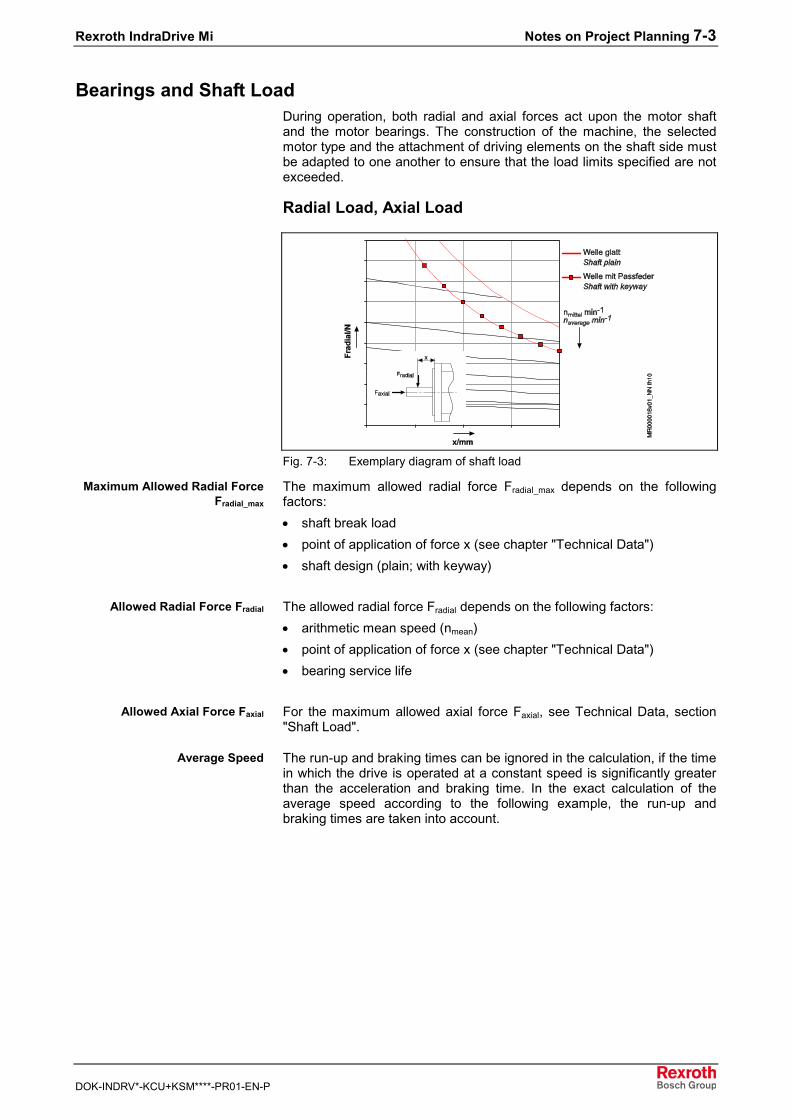
Rexroth IndraDrive Mi Notes on Project Planning 7-3
DOK-INDRV*-KCU+KSM****-PR01-EN-P
Bearings and Shaft LoadDuring operation, both radial and axial forces act upon the motor shaftand the motor bearings. The construction of the machine, the selectedmotor type and the attachment of driving elements on the shaft side mustbe adapted to one another to ensure that the load limits specified are notexceeded.
Radial Load, Axial Load
Fig. 7-3: Exemplary diagram of shaft load
The maximum allowed radial force Fradial_max depends on the followingfactors:• shaft break load• point of application of force x (see chapter "Technical Data")• shaft design (plain; with keyway)
The allowed radial force Fradial depends on the following factors:• arithmetic mean speed (nmean)• point of application of force x (see chapter "Technical Data")• bearing service life
For the maximum allowed axial force Faxial, see Technical Data, section"Shaft Load".
The run-up and braking times can be ignored in the calculation, if the timein which the drive is operated at a constant speed is significantly greaterthan the acceleration and braking time. In the exact calculation of theaverage speed according to the following example, the run-up andbraking times are taken into account.
Maximum Allowed Radial ForceFradial_max
Allowed Radial Force Fradial
Allowed Axial Force Faxial
Average Speed
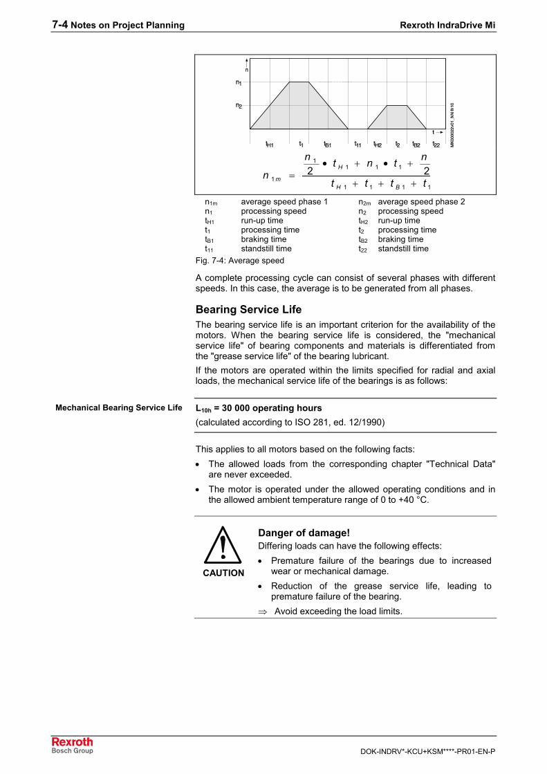
7-4 Notes on Project Planning Rexroth IndraDrive Mi
DOK-INDRV*-KCU+KSM****-PR01-EN-P
1111
1111
1
122tttt
ntntn
nBH
H
m +++
+•+•=
n1m average speed phase 1 n2m average speed phase 2n1 processing speed n2 processing speedtH1 run-up time tH2 run-up timet1 processing time t2 processing timetB1 braking time tB2 braking timet11 standstill time t22 standstill time
Fig. 7-4: Average speed
A complete processing cycle can consist of several phases with differentspeeds. In this case, the average is to be generated from all phases.
Bearing Service LifeThe bearing service life is an important criterion for the availability of themotors. When the bearing service life is considered, the "mechanicalservice life" of bearing components and materials is differentiated fromthe "grease service life" of the bearing lubricant.If the motors are operated within the limits specified for radial and axialloads, the mechanical service life of the bearings is as follows:
L10h = 30 000 operating hours(calculated according to ISO 281, ed. 12/1990)
This applies to all motors based on the following facts:• The allowed loads from the corresponding chapter "Technical Data"
are never exceeded.• The motor is operated under the allowed operating conditions and in
the allowed ambient temperature range of 0 to +40 °C.
CAUTION
Danger of damage!Differing loads can have the following effects:• Premature failure of the bearings due to increased
wear or mechanical damage.• Reduction of the grease service life, leading to
premature failure of the bearing.⇒ Avoid exceeding the load limits.
Mechanical Bearing Service Life
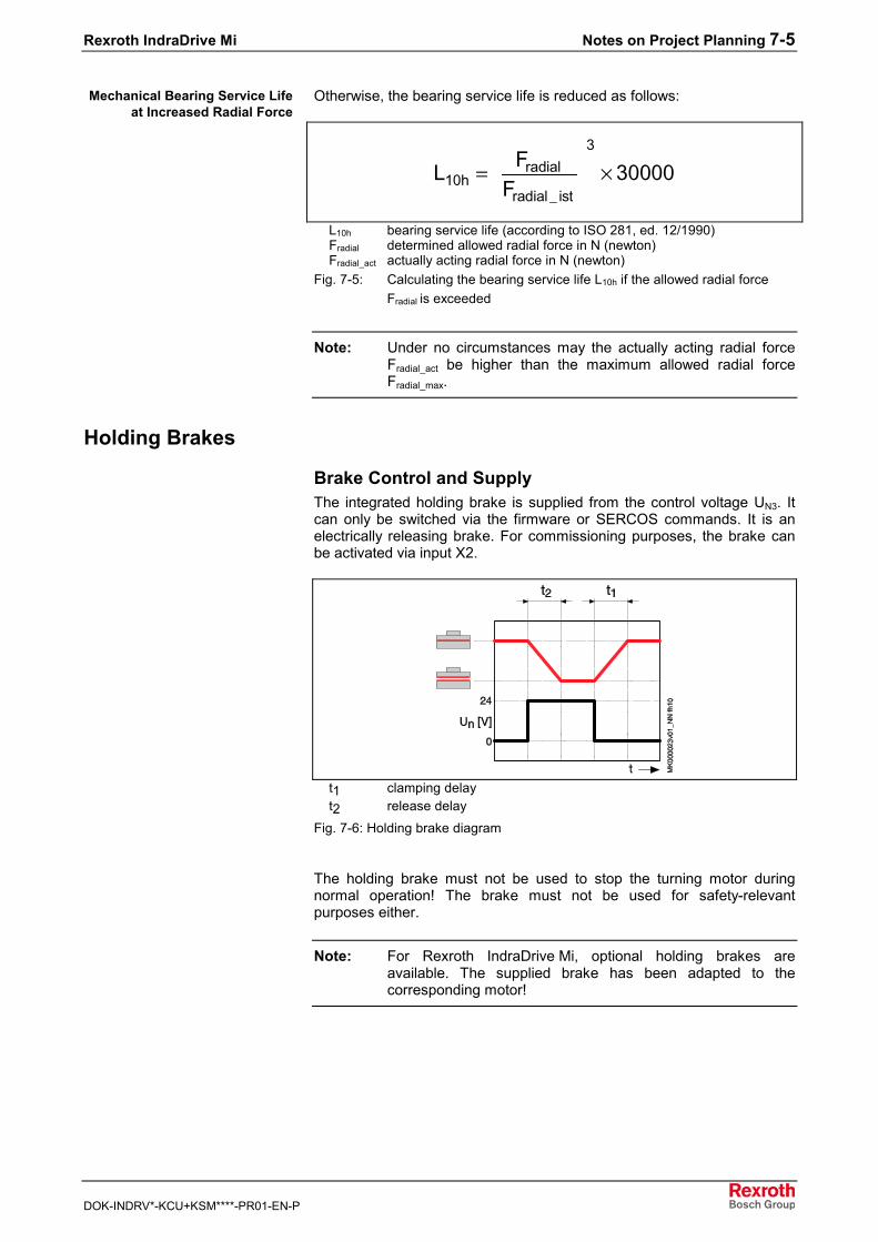
Rexroth IndraDrive Mi Notes on Project Planning 7-5
DOK-INDRV*-KCU+KSM****-PR01-EN-P
Otherwise, the bearing service life is reduced as follows:
3radial
10hradial ist
FL 30000F _
= ×
L10h bearing service life (according to ISO 281, ed. 12/1990)Fradial determined allowed radial force in N (newton)Fradial_act actually acting radial force in N (newton)
Fig. 7-5: Calculating the bearing service life L10h if the allowed radial forceFradial is exceeded
Note: Under no circumstances may the actually acting radial forceFradial_act be higher than the maximum allowed radial forceFradial_max.
Holding Brakes
Brake Control and SupplyThe integrated holding brake is supplied from the control voltage UN3. Itcan only be switched via the firmware or SERCOS commands. It is anelectrically releasing brake. For commissioning purposes, the brake canbe activated via input X2.
t1 clamping delayt2 release delay
Fig. 7-6: Holding brake diagram
The holding brake must not be used to stop the turning motor duringnormal operation! The brake must not be used for safety-relevantpurposes either.
Note: For Rexroth IndraDrive Mi, optional holding brakes areavailable. The supplied brake has been adapted to thecorresponding motor!
Mechanical Bearing Service Lifeat Increased Radial Force
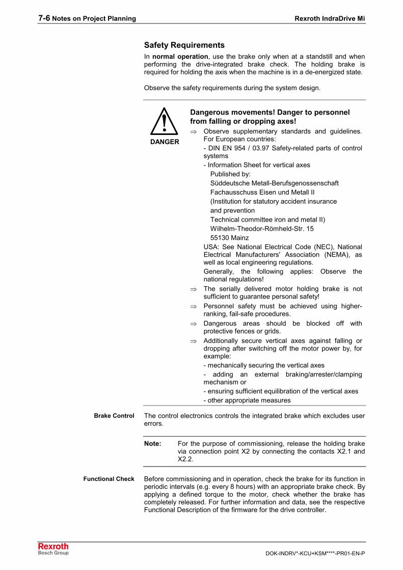
7-6 Notes on Project Planning Rexroth IndraDrive Mi
DOK-INDRV*-KCU+KSM****-PR01-EN-P
Safety RequirementsIn normal operation, use the brake only when at a standstill and whenperforming the drive-integrated brake check. The holding brake isrequired for holding the axis when the machine is in a de-energized state.
Observe the safety requirements during the system design.
DANGER
Dangerous movements! Danger to personnelfrom falling or dropping axes!⇒ Observe supplementary standards and guidelines.
For European countries: - DIN EN 954 / 03.97 Safety-related parts of controlsystems- Information Sheet for vertical axes Published by: Süddeutsche Metall-Berufsgenossenschaft Fachausschuss Eisen und Metall II (Institution for statutory accident insurance and prevention Technical committee iron and metal II) Wilhelm-Theodor-Römheld-Str. 15 55130 MainzUSA: See National Electrical Code (NEC), NationalElectrical Manufacturers' Association (NEMA), aswell as local engineering regulations. Generally, the following applies: Observe thenational regulations!
⇒ The serially delivered motor holding brake is notsufficient to guarantee personal safety!
⇒ Personnel safety must be achieved using higher-ranking, fail-safe procedures.
⇒ Dangerous areas should be blocked off withprotective fences or grids.
⇒ Additionally secure vertical axes against falling ordropping after switching off the motor power by, forexample:- mechanically securing the vertical axes- adding an external braking/arrester/clampingmechanism or- ensuring sufficient equilibration of the vertical axes- other appropriate measures
The control electronics controls the integrated brake which excludes usererrors.
Note: For the purpose of commissioning, release the holding brakevia connection point X2 by connecting the contacts X2.1 andX2.2.
Before commissioning and in operation, check the brake for its function inperiodic intervals (e.g. every 8 hours) with an appropriate brake check. Byapplying a defined torque to the motor, check whether the brake hascompletely released. For further information and data, see the respectiveFunctional Description of the firmware for the drive controller.
Brake Control
Functional Check
Rexroth IndraDrive Mi Notes on Project Planning 7-7
DOK-INDRV*-KCU+KSM****-PR01-EN-P
The electrically releasing holding brake is used to hold the axes at astandstill and when the drive enable signal is off. When the supply voltagefails and the drive enable signal has been switched off, the electricallyreleasing holding brake will automatically apply.
CAUTION
Danger of damage!If the brake is engaged repeatedly on a drive in motion orthe allowed braking energy is exceeded, premature brakewear can occur.⇒ Do not use the holding brake as a service brake for
moving axes.
Dimensioning Holding BrakesThe physical conditions of holding brakes require consideration of twostates. In addition to normal operation, failures must be considered. Theeffective braking torques are physically different:
In normal operation, using the holding brake for clamping (holding) anaxis in standstill, the "static holding torque" (M4) – static friction (frictioncoefficient µH) specified in the data sheets takes effect.
In the case of failure (E-Stop), where the holding brake is used todecelerate a moving axis, the "dynamic braking torque" – sliding friction(friction coefficient µG) applies.The dynamic braking torque is lower than the indicated static holdingtorque M4. It is approx. 0.75 … 0.8 x M4. Therefore, observe the followingdescription of dynamic dimensioning.
The load torque must be lower than the minimum dynamic torque whichthe brake can provide. Otherwise, the dynamic brake torque is notsufficient to stop the axis.If a mass is to be decelerated in a defined time or over a defineddistance, the mass inertia of the whole system must be additionally takeninto account.
The holding brake is not a safety brake (cf. DIN EN 954 / 03.97 andInformation Sheet for vertical axes published by the institution for statutoryaccident insurance and prevention ["Süddeutsche Metall-Berufsgenossenschaft"]). Due to uncontrollable disturbances, such as filmrust on the brake friction surface, the holding brake torque can bereduced. Additionally, overvoltage and too high temperatures can weakenthe permanent magnets and the brake.
Considering these factors, the following recommendation can be given fordimensioning holding brakes at axes:The holding torque required for the application must not exceed amaximum of 60% of the static holding torque (M4) of the holdingbrake used.
Electrically Releasing HoldingBrake
Normal Operation
Failure (E-Stop)
Dynamic Dimensioning
Other Important Aspects forDimensioning
Dimensioning -Recommendation
7-8 Notes on Project Planning Rexroth IndraDrive Mi
DOK-INDRV*-KCU+KSM****-PR01-EN-P
CAUTION
Holding torque reduction and premature wearoccur when braking moving axes!⇒ Do not use the holding brake to stop a moving axis
during normal operation. This is allowed for E-Stopsituations only. In this situation, the specified ratedtorque of the holding brake (M4) is reduced to thedynamic braking torque. Complete deterioration ofthe holding brake can be expected after approx.20,000 revolutions of the brake when applied.
Observe the notes on commissioning for holding brakes in chapter"Commissioning, Operation, Diagnoses, Service and Maintenance".
Mechanical Attachment of Driving ElementsFor all attachments of driving elements to the output shaft, such as• gears• couplings• pinions,you absolutely have to observe the following instructions.
Redundant BearingsGenerally, redundant bearings are to be avoided by all means whenattaching driving elements. The tolerances inevitably present in suchcases will lead to additional forces acting on the bearing of the motorshaft and, should the occasion arise, to a distinctly reduced service life ofthe bearing.
Note: If redundant attachment cannot be avoided, it is absolutelynecessary that you consult Bosch Rexroth.
Gear AttachmentThe machine construction and the attachment elements used must becarefully adapted to the motor type so that the load limits of shaft andbearing are not exceeded.When gears are attached to motors, this changes the thermal connectionof the motor to the machine or installation construction.According to the gear type, the heat generation at the gear is different. Inany case, gear attachment reduces the heat dissipation of the motor viathe flange. This has to be taken into account when doing the projectplanning for the installation.To avoid thermal overload of motors when using gears, it is necessary toreduce the specified performance data.
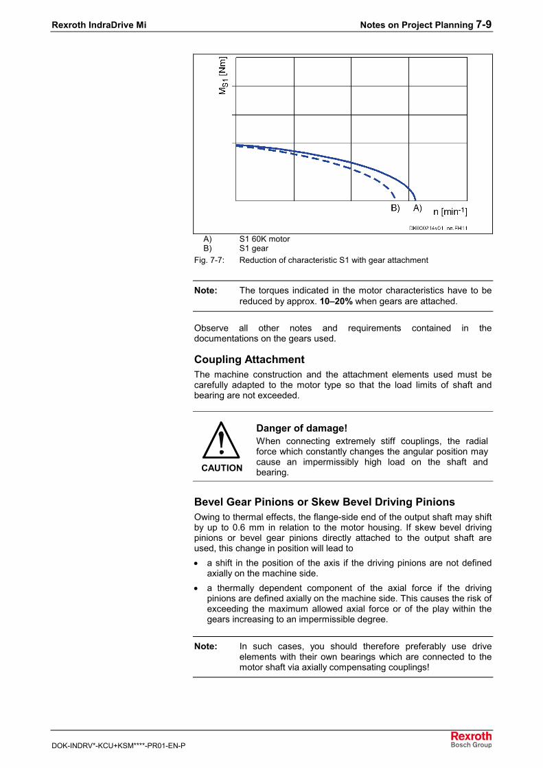
Rexroth IndraDrive Mi Notes on Project Planning 7-9
DOK-INDRV*-KCU+KSM****-PR01-EN-P
A) S1 60K motorB) S1 gear
Fig. 7-7: Reduction of characteristic S1 with gear attachment
Note: The torques indicated in the motor characteristics have to bereduced by approx. 10–20% when gears are attached.
Observe all other notes and requirements contained in thedocumentations on the gears used.
Coupling AttachmentThe machine construction and the attachment elements used must becarefully adapted to the motor type so that the load limits of shaft andbearing are not exceeded.
CAUTION
Danger of damage!When connecting extremely stiff couplings, the radialforce which constantly changes the angular position maycause an impermissibly high load on the shaft andbearing.
Bevel Gear Pinions or Skew Bevel Driving PinionsOwing to thermal effects, the flange-side end of the output shaft may shiftby up to 0.6 mm in relation to the motor housing. If skew bevel drivingpinions or bevel gear pinions directly attached to the output shaft areused, this change in position will lead to• a shift in the position of the axis if the driving pinions are not defined
axially on the machine side.• a thermally dependent component of the axial force if the driving
pinions are defined axially on the machine side. This causes the risk ofexceeding the maximum allowed axial force or of the play within thegears increasing to an impermissible degree.
Note: In such cases, you should therefore preferably use driveelements with their own bearings which are connected to themotor shaft via axially compensating couplings!

7-10 Notes on Project Planning Rexroth IndraDrive Mi
DOK-INDRV*-KCU+KSM****-PR01-EN-P
7.2 Notes on Electrical Project Planning
Allowed Cable Lengths
Description Symbol Unit Valuemax. allowed total length 1) ltotal m 200
max. allowed segment length 2) lseg m 751) total length: total cable length from connection point KCU to last
KSM of a string of drives2) segment length: cable length between tow KSM
Fig. 7-8: Allowed cable length with fixed routing
Description Symbol Unit Valuemax. allowed total length ltotal m in preparation
max. allowed length in cable dragchain
lschlepp m in preparation
max. allowed segment length lseg m in preparation
max. allowed segment length incable drag chain
lseg_schlepp m in preparation
Fig. 7-9: Allowed cable length with routing with cable drag chain
Maximum Number of Axes per System CombinationThe maximum allowed number of axes in a system combination ofseveral Rexroth IndraDrive Mi at a supply unit is limited by the followingvariables:• signal exchange between KCU and KSM with max. 20 axes• continuous current of motor cable (hybrid cable) of max. DC 25 A• peak current of motor cable (hybrid cable) of max. DC 75 A• allowed total cable length see section "Maximum Cable Length vs.
Number of Axes"
Continuous Power Motor CableThe motor cable can be continuously loaded with DC 25 A; withuncontrolled supply unit (HMV-E) and a mains voltage of AC 400V -5%,this corresponds to a DC continuous power of 12 kW. Accordingly, thesum of electrical continuous motor powers at a string of drives may be upto 12 kW. With controlled DC bus voltage (DC 750 V), it is possible tohave 18 kW.For calculating the total power: see formulas in chapter "Calculations" ofdocumentation "Rexroth IndraDrive, Drive System, Project PlanningManual". Taking the average speed and simultaneity factor into account,the total installable motor power can be significantly higher with servooperation.
Peak Power Motor CableDue to voltage drop on the motor cable, the transmittable DC peak powerdecreases as the cable length increases. With triple overload capability ofcable and fuses, the resulting temporary peak current is DC 75 A. Unlikethe acceleration power, the braking power does not depend on thecorresponding DC bus voltage, because the voltage when braking isalways at least DC 750 V. The voltage limitation at the motors required forbraking is the reason for the derating as of 80 m of cable length.
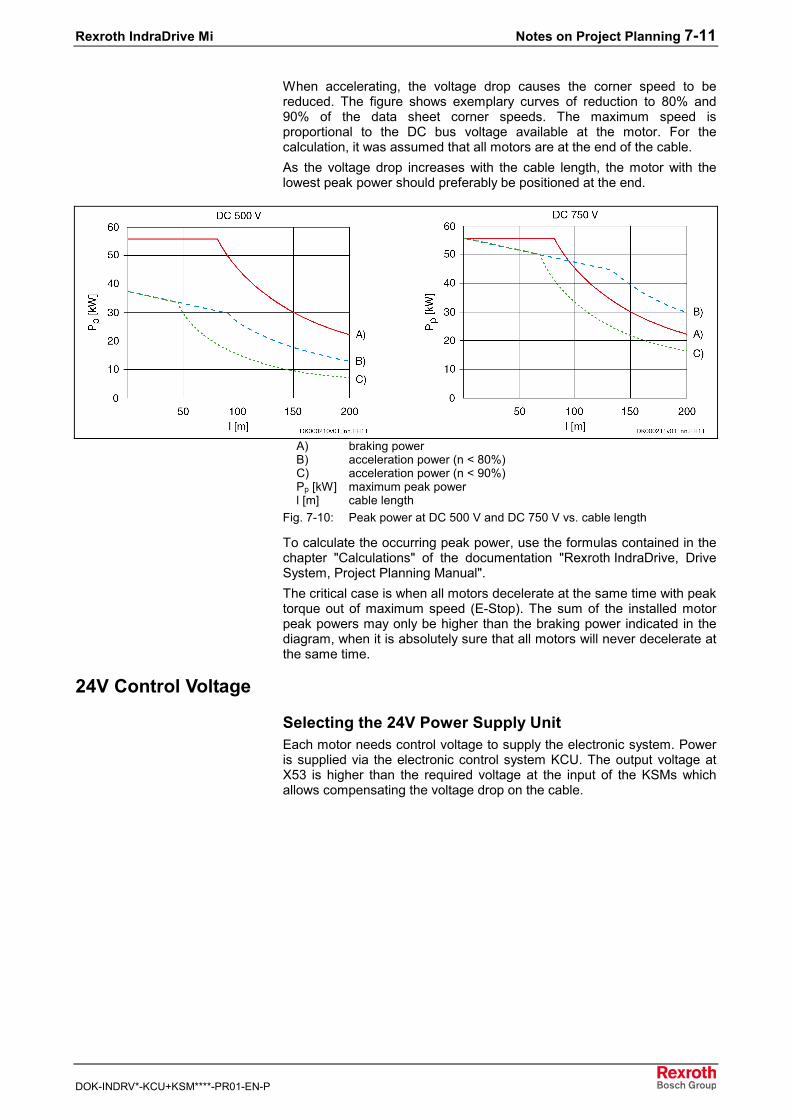
Rexroth IndraDrive Mi Notes on Project Planning 7-11
DOK-INDRV*-KCU+KSM****-PR01-EN-P
When accelerating, the voltage drop causes the corner speed to bereduced. The figure shows exemplary curves of reduction to 80% and90% of the data sheet corner speeds. The maximum speed isproportional to the DC bus voltage available at the motor. For thecalculation, it was assumed that all motors are at the end of the cable.As the voltage drop increases with the cable length, the motor with thelowest peak power should preferably be positioned at the end.
A) braking powerB) acceleration power (n < 80%)C) acceleration power (n < 90%)Pp [kW] maximum peak powerl [m] cable length
Fig. 7-10: Peak power at DC 500 V and DC 750 V vs. cable length
To calculate the occurring peak power, use the formulas contained in thechapter "Calculations" of the documentation "Rexroth IndraDrive, DriveSystem, Project Planning Manual".The critical case is when all motors decelerate at the same time with peaktorque out of maximum speed (E-Stop). The sum of the installed motorpeak powers may only be higher than the braking power indicated in thediagram, when it is absolutely sure that all motors will never decelerate atthe same time.
24V Control Voltage
Selecting the 24V Power Supply UnitEach motor needs control voltage to supply the electronic system. Poweris supplied via the electronic control system KCU. The output voltage atX53 is higher than the required voltage at the input of the KSMs whichallows compensating the voltage drop on the cable.
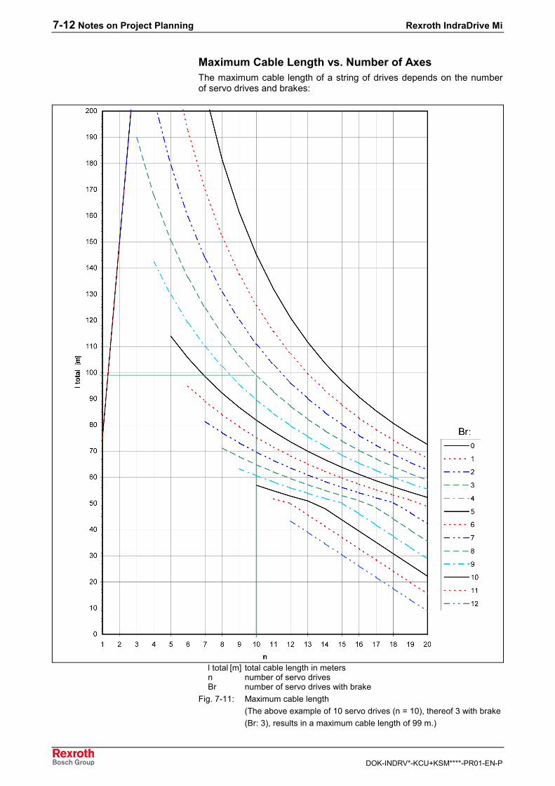
7-12 Notes on Project Planning Rexroth IndraDrive Mi
DOK-INDRV*-KCU+KSM****-PR01-EN-P
Maximum Cable Length vs. Number of AxesThe maximum cable length of a string of drives depends on the numberof servo drives and brakes:
l total [m] total cable length in metersn number of servo drivesBr number of servo drives with brake
Fig. 7-11: Maximum cable length(The above example of 10 servo drives (n = 10), thereof 3 with brake(Br: 3), results in a maximum cable length of 99 m.)
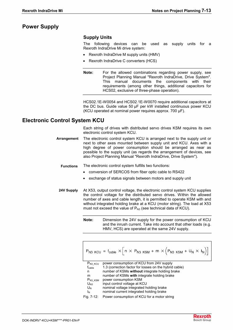
Rexroth IndraDrive Mi Notes on Project Planning 7-13
DOK-INDRV*-KCU+KSM****-PR01-EN-P
Power Supply
Supply UnitsThe following devices can be used as supply units for aRexroth IndraDrive Mi drive system:• Rexroth IndraDrive M supply units (HMV)• Rexroth IndraDrive C converters (HCS)
Note: For the allowed combinations regarding power supply, seeProject Planning Manual "Rexroth IndraDrive, Drive System".This manual documents the components with theirrequirements (among other things, additional capacitors forHCS02, exclusive of three-phase operation).
HCS02.1E-W0054 and HCS02.1E-W0070 require additional capacitors atthe DC bus. Guide value 50 µF per kW installed continuous power KCU(KCU operated at nominal power requires approx. 700 µF).
Electronic Control System KCUEach string of drives with distributed servo drives KSM requires its ownelectronic control system KCU.The electronic control system KCU is arranged next to the supply unit ornext to other axes mounted between supply unit and KCU. Axes with ahigh degree of power consumption should be arranged as near aspossible to the supply unit (as regards the arrangement of devices, seealso Project Planning Manual "Rexroth IndraDrive, Drive System").
The electronic control system fulfills two functions:• conversion of SERCOS from fiber optic cable to RS422• exchange of status signals between motors and supply unit
At X53, output control voltage, the electronic control system KCU suppliesthe control voltage for the distributed servo drives. Within the allowednumber of axes and cable length, it is permitted to operate KSM with andwithout integrated holding brake at a KCU (motor string). The load at X53must not exceed the value of PN3 (see technical data of KCU).
Note: Dimension the 24V supply for the power consumption of KCUand the inrush current. Take into account that other loads (e.g.HMV, HCS) are operated at the same 24V supply.
PN3_KCU power consumption of KCU from 24V supplyfcable 1.3 (correction factor for losses on the hybrid cable)n number of KSMs without integrate holding brakem number of KSMs with integrate holding brakePN3_KSM power consumption KSMUN3 input control voltage at KCUUN nominal voltage integrated holding brakeIN nominal current integrated holding brake
Fig. 7-12: Power consumption of KCU for a motor string
Arrangement
Functions
24V Supply
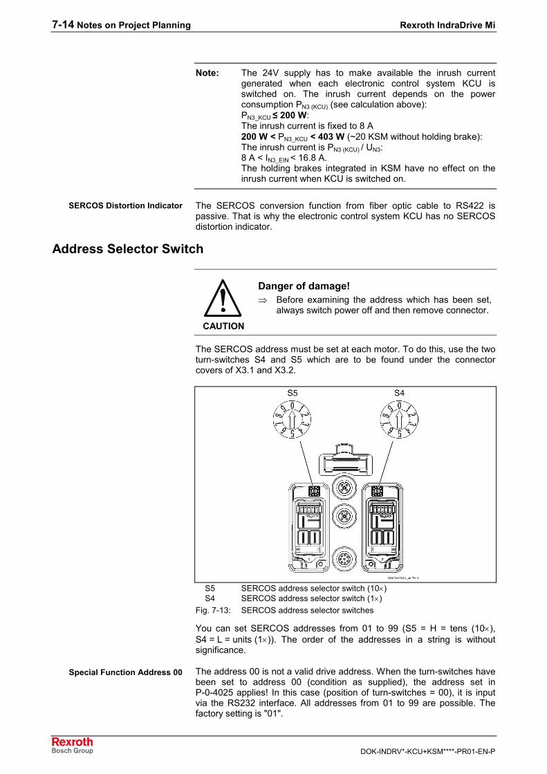
7-14 Notes on Project Planning Rexroth IndraDrive Mi
DOK-INDRV*-KCU+KSM****-PR01-EN-P
Note: The 24V supply has to make available the inrush currentgenerated when each electronic control system KCU isswitched on. The inrush current depends on the powerconsumption PN3 (KCU) (see calculation above):PN3_KCU ≤ 200 W:The inrush current is fixed to 8 A 200 W < PN3_KCU < 403 W (~20 KSM without holding brake):The inrush current is PN3 (KCU) / UN3:8 A < IN3_EIN < 16.8 A.The holding brakes integrated in KSM have no effect on theinrush current when KCU is switched on.
The SERCOS conversion function from fiber optic cable to RS422 ispassive. That is why the electronic control system KCU has no SERCOSdistortion indicator.
Address Selector Switch
CAUTION
Danger of damage!⇒ Before examining the address which has been set,
always switch power off and then remove connector.
The SERCOS address must be set at each motor. To do this, use the twoturn-switches S4 and S5 which are to be found under the connectorcovers of X3.1 and X3.2.
S5 SERCOS address selector switch (10×)S4 SERCOS address selector switch (1×)
Fig. 7-13: SERCOS address selector switches
You can set SERCOS addresses from 01 to 99 (S5 = H = tens (10×),S4 = L = units (1×)). The order of the addresses in a string is withoutsignificance.
The address 00 is not a valid drive address. When the turn-switches havebeen set to address 00 (condition as supplied), the address set inP-0-4025 applies! In this case (position of turn-switches = 00), it is inputvia the RS232 interface. All addresses from 01 to 99 are possible. Thefactory setting is "01".
SERCOS Distortion Indicator
Special Function Address 00
Rexroth IndraDrive Mi Notes on Project Planning 7-15
DOK-INDRV*-KCU+KSM****-PR01-EN-P
Motor BlowerBlowers are not available for Rexroth IndraDrive Mi.
Motor Current LimitationThe current limitation makes sure that neither controller nor motor aredamaged by overload, as long as the motor temperature remains below100 °C. When the housing temperature of 100 °C is exceeded,overtemperature shutdown takes place.With a load of more than 200%, the I2t limitation takes effect. It limits thetemperature of winding and electronic system to the safe working range.In standstill (turning shaft n < ~60 min-1), the current is limited in a morerestrictive way, due to the concentration of losses to one phase. Forbigger motors, the continuous torque at standstill can be less than 200%of the continuous torque at standstill 60 K.The limitation starts at 100% of thermal drive load (P-0-0141). To havereserve capacity (e.g. for dynamic processes or increased friction), youshould dimension the drive system with less than 80% of thermal driveload. You have to check the drive load during initial commissioning.
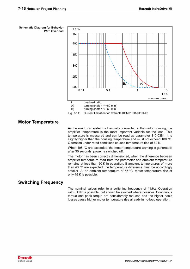
7-16 Notes on Project Planning Rexroth IndraDrive Mi
DOK-INDRV*-KCU+KSM****-PR01-EN-P
k overload ratioA) turning shaft n > ~60 min-1
B) turning shaft n < ~60 min-1
Fig. 7-14: Current limitation for example KSM01.2B-041C-42
Motor TemperatureAs the electronic system is thermally connected to the motor housing, theamplifier temperature is the most important variable for the load. Thistemperature is measured and can be read as parameter S-0-0384. It isslightly higher than the housing temperature and must not exceed 100 °C.Operation under rated conditions causes temperature rise of 60 K.When 105 °C are exceeded, the motor temperature warning is generated;after 30 seconds, power is switched off.The motor has been correctly dimensioned, when the difference betweenamplifier temperature read from the parameter and ambient temperatureremains at less than 60 K in operation. If ambient temperatures of morethan 40 °C are expected, the temperature difference must be accordinglysmaller. At an ambient temperature of 55 °C, motor temperature rise ofonly 45 K is possible.
Switching FrequencyThe nominal values refer to a switching frequency of 4 kHz. Operationwith 8 kHz is possible, but should be avoided where possible. Continuoustorque and peak torque are considerably reduced and the higher basiclosses cause higher motor temperature rise already in no-load operation.
Schematic Diagram for BehaviorWith Overload
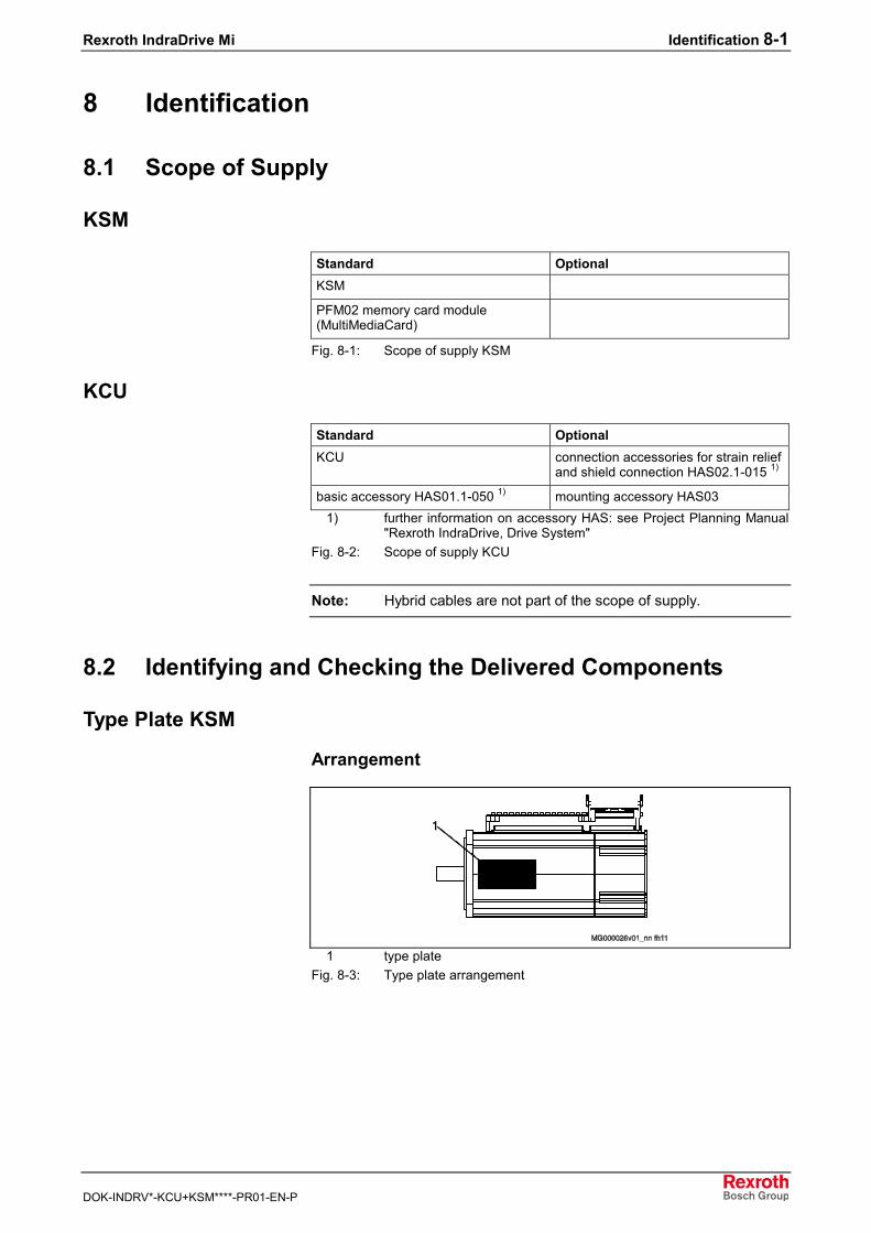
Rexroth IndraDrive Mi Identification 8-1
DOK-INDRV*-KCU+KSM****-PR01-EN-P
8 Identification
8.1 Scope of Supply
KSM
Standard OptionalKSM
PFM02 memory card module(MultiMediaCard)
Fig. 8-1: Scope of supply KSM
KCU
Standard OptionalKCU connection accessories for strain relief
and shield connection HAS02.1-015 1)
basic accessory HAS01.1-050 1) mounting accessory HAS031) further information on accessory HAS: see Project Planning Manual
"Rexroth IndraDrive, Drive System"Fig. 8-2: Scope of supply KCU
Note: Hybrid cables are not part of the scope of supply.
8.2 Identifying and Checking the Delivered Components
Type Plate KSM
Arrangement
1 type plateFig. 8-3: Type plate arrangement
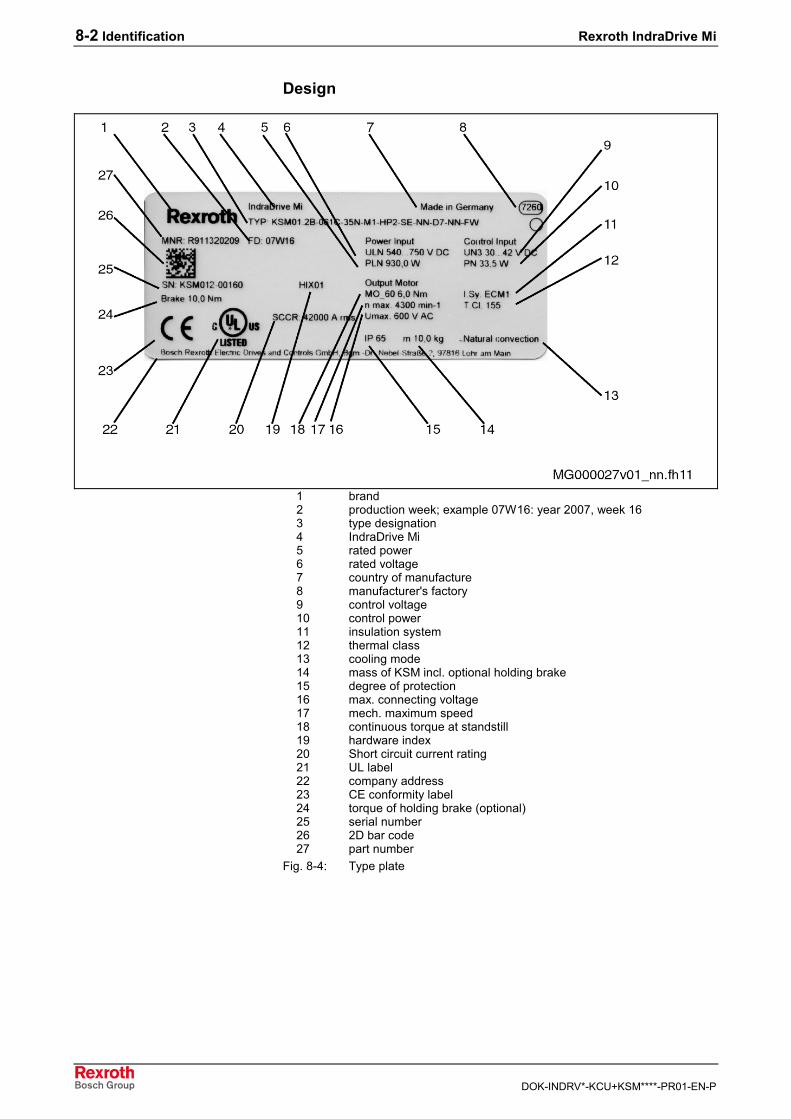
8-2 Identification Rexroth IndraDrive Mi
DOK-INDRV*-KCU+KSM****-PR01-EN-P
Design
1 brand2 production week; example 07W16: year 2007, week 163 type designation4 IndraDrive Mi5 rated power6 rated voltage7 country of manufacture8 manufacturer's factory9 control voltage10 control power11 insulation system12 thermal class13 cooling mode14 mass of KSM incl. optional holding brake15 degree of protection16 max. connecting voltage17 mech. maximum speed18 continuous torque at standstill19 hardware index20 Short circuit current rating21 UL label22 company address23 CE conformity label24 torque of holding brake (optional)25 serial number26 2D bar code27 part number
Fig. 8-4: Type plate
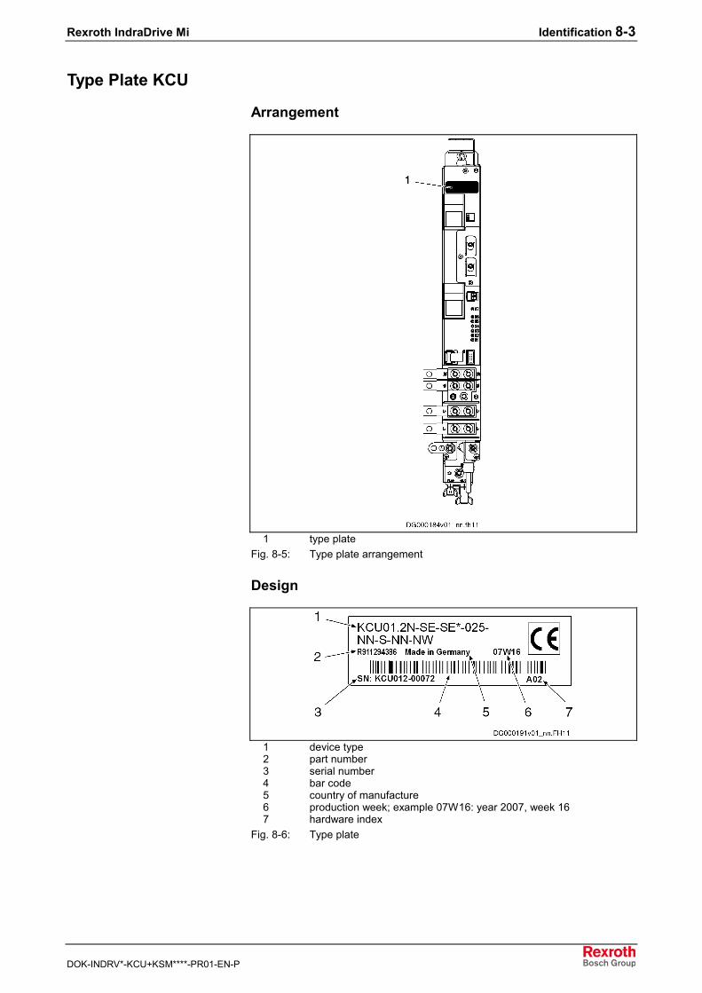
Rexroth IndraDrive Mi Identification 8-3
DOK-INDRV*-KCU+KSM****-PR01-EN-P
Type Plate KCU
Arrangement
1 type plateFig. 8-5: Type plate arrangement
Design
1 device type2 part number3 serial number4 bar code5 country of manufacture6 production week; example 07W16: year 2007, week 167 hardware index
Fig. 8-6: Type plate

8-4 Identification Rexroth IndraDrive Mi
DOK-INDRV*-KCU+KSM****-PR01-EN-P
Rexroth IndraDrive Mi Mounting and Installation 9-1
DOK-INDRV*-KCU+KSM****-PR01-EN-P
9 Mounting and Installation
9.1 Introduction
Important Notes
Safety
WARNING
Injuries caused by live parts! Lifting of heavyloads!⇒ Install the motors only when they have been de-
energized and are not connected electrically.⇒ Use suitable tackles, protective equipment and
protective clothing during transport.⇒ Observe the safety instructions contained in the
preceding chapters.
Carry out all working steps especially carefully. In this way, you minimizethe risk of accidents and damages.
Qualified Technical StaffAny work at the installation and the drives or in their vicinity may becarried out only by appropriately trained technical staff.Make sure that all persons carrying out• installation work• maintenance work or• operational activitiesat the installation are adequately familiar with the contents of thisdocumentation, as well as with all warnings and precautionary measurescontained therein.Qualified technical staff must be trained, instructed and qualified to switchelectrical circuits and devices on and off in accordance with technicalsafety regulations, to ground them and to mark them. Qualified technicalstaff must possess appropriate safety equipment and have been trainedin first aid.
System Overview
Available ConnectionsThe electrical connections of all sizes of Rexroth IndraDrive Mi motorshave been standardized.The motors are provided with• two power connections (hybrid connectors for power, control voltage,
master communication and status messages) to loop through the buscable
• two I/O connectors (M12, 5-pin)• one RS232 interface (M12, 8-pin)
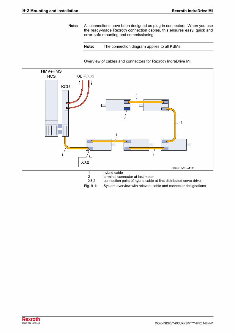
9-2 Mounting and Installation Rexroth IndraDrive Mi
DOK-INDRV*-KCU+KSM****-PR01-EN-P
All connections have been designed as plug-in connectors. When you usethe ready-made Rexroth connection cables, this ensures easy, quick anderror-safe mounting and commissioning.
Note: The connection diagram applies to all KSMs!
Overview of cables and connectors for Rexroth IndraDrive Mi:
1 hybrid cable2 terminal connector at last motorX3.2 connection point of hybrid cable at first distributed servo drive
Fig. 9-1: System overview with relevant cable and connector designations
Notes
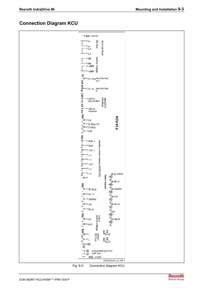
Rexroth IndraDrive Mi Mounting and Installation 9-3
DOK-INDRV*-KCU+KSM****-PR01-EN-P
Connection Diagram KCU
Fig. 9-2: Connection diagram KCU
9-4 Mounting and Installation Rexroth IndraDrive Mi
DOK-INDRV*-KCU+KSM****-PR01-EN-P
9.2 Mounting
Practical Tips
General InformationObserve the following aspects for installation and mounting:• The motors have been equipped with two power connectors X3.1 and
X3.2 which allow looping through the motor cable. Both connectionpoints are basically equivalent. According to the configuration, the lastmotor is provided with a terminal connector at X3.1 or X3.2.
• In the motor cable (bus cable), the SERCOS signals are nottransmitted via fiber optic cable, but via RS422. That is why theelectronic control system KCU contains a converter from fiber opticcable to RS422 and back. The typical SERCOS ring structure ismaintained in the motor cable. First, the signal goes up to the lastmotor, is redirected in the terminal connector and then goes back to itsstarting point.
• Each motor refreshes (repeats) the SERCOS signal only in thedirection of X3.1 to X3.2. In the direction of X3.2 to X3.1, merely anamplifier without repeater function has been installed.
Optimum CablingThe cabling illustrated in figure "System overview with relevant cable andconnector designations" ensures that the SERCOS signal is repeated inevery second motor, both on its way to the KSMs and on its way back. Inaddition, the control unit (SERCOS master) gets back a freshly repeatedSERCOS signal from the first motor. For this purpose, the cable comingfrom the supply unit must have been plugged in X3.2 of the first motor.Particularly with 16 Mbaud, the maximum cable lengths can only berealized with this kind of interconnection.
CAUTION
Danger of damage!⇒ Never remove live motor connectors (X3.1, X3.2).
Required Steps to Follow
PreparationsMake the following preparations to mount the motor:1. Procure tools, auxiliary materials, measuring and test equipment.2. Check all components for visible damage. Defective components
must not be mounted.3. Ensure that dimensions and tolerances on the installation side are
suitable for motor attachment (for details, see dimensional drawing).4. Check whether all components, mounting surfaces and threads are
clean.5. Ensure that mounting can be done in a dry and dust-free
environment.6. Ensure that the holder for the motor flange is without burrs.7. Remove the protective sleeve of the motor shaft and keep it for
further use.

Rexroth IndraDrive Mi Mounting and Installation 9-5
DOK-INDRV*-KCU+KSM****-PR01-EN-P
8. Check whether the motor holding brake attains the holding torquespecified in the data sheet. If the brake does not attain the specifiedtorque, first proceed as described in chapter "Commissioning,Operation, Diagnoses, Service and Maintenance" → "Maintenance"→ "Holding Brake".
MountingObserve the following aspects when mounting the motor:1. Avoid jamming or getting stuck of the centering collar on the motor
side.2. Avoid damage to the insertion fitting on the installation side.3. Check the stability and precision of the connection before you
proceed.
After proper mechanical mounting, proceed with the electricalconnections.
Mechanical Interfaces
Mounting the FlangeDistributed servo drives KSM are manufactured for flange mounting (typeof construction B05). Details for the fastening holes can be found in thecorresponding dimensional drawing.To fasten the flange, we recommend using the screws and tighteningtorques listed in the table below.
Motor size Recommendedscrew size
Tighteningtorque [Nm]
Minimumstrength
KSM01.2B-041 M6 10,4 8.8
KSM01.2B-061 M8 25 8.8
KSM01.2B-071KSM01.2B-076 M10 51 8.8
The screw specifications apply when screwed in steel; for other materials,determine the reach of the screws.
Fig. 9-3: Fastening screws
Note: The screwed connections must be able to take up both theforce due to weight of the motor and the forces acting duringoperation.
If the Optional Holding Brake isUsed
9-6 Mounting and Installation Rexroth IndraDrive Mi
DOK-INDRV*-KCU+KSM****-PR01-EN-P
9.3 Electrical Connection
DANGER
Danger to life due to electric voltage! Handlingwithin the range of live parts is extremelydangerous. Therefore:⇒ Any work required on the electric system may be
carried out only by skilled electricians. It is absolutelynecessary to use power tools.
⇒ Before starting work, the system must be de-energized and the power switch be secured againstunintentional or unauthorized re-energization.
⇒ Before starting work, the appropriate measuringequipment must be used to check whether parts ofthe system are still under residual voltage (e.g.caused by capacitors, etc.). Wait to allow the systemto discharge or use an appropriate discharging device(see chapter "Appendix").
WARNING
Personal injury or property damage!Interrupting or connecting live lines may causeunpredictable dangerous situations or lead toproperty damage. Therefore:⇒ Connect and disconnect plug-in connectors only
when they are dry and de-energized.⇒ During operation of the installation, all plug-in
connectors must be locked.
WARNING
Risk of short circuit caused by liquid coolant orlubricant! Short circuits of live lines may causeunpredictable dangerous situations or lead toproperty damage. Therefore:⇒ Provide open mating sides of power plug-in
connectors with safety caps when installing orreplacing drive components, if you cannot excludethat they might be moistened with liquid coolant orlubricant.
Rexroth IndraDrive Mi Mounting and Installation 9-7
DOK-INDRV*-KCU+KSM****-PR01-EN-P
NotesThe motor cable is a hybrid cable in which the communication line hasbeen integrated, too. Only the original Rexroth cable can ensure thefunction. It is supplied as ready-made cable. The outgoing direction of thehybrid cable cannot be changed subsequently!
CAUTION
Risk of damage by subsequently changing theoutgoing direction of the hybrid cable!⇒ Do not try to reverse a ready-made connector with
cable outgoing direction A (B) to outgoingdirection B (A)! The flexible leads in the connectorhave individual lengths for each outgoing direction.
When ordering the ready-made hybrid cables, always indicate the desiredoutgoing directions (A or B): see chapter "Technical Data of theComponents, Hybrid Cables".Ready-made hybrid cables have been coded in such a way that X3.1 andX3.2 cannot be interchanged when connecting the cables.
Electrical Interfaces
Overall Connection Diagram
Note: At the first distributed servo drive KSM, always plug the cablein X3.2.Always terminate the unassigned connection at the lastdistributed servo drive KSM with a terminal connector.
The figure below shows an example. Other possibilities of mainsconnection are described in the Project Planning Manual "RexrothIndraDrive, Drive System".The additional components (DST, HNL, HNF …) contained in the figureare not absolutely necessary. As regards the detailed configuration of adrive system, see Project Planning Manual "Rexroth IndraDrive, DriveSystem".
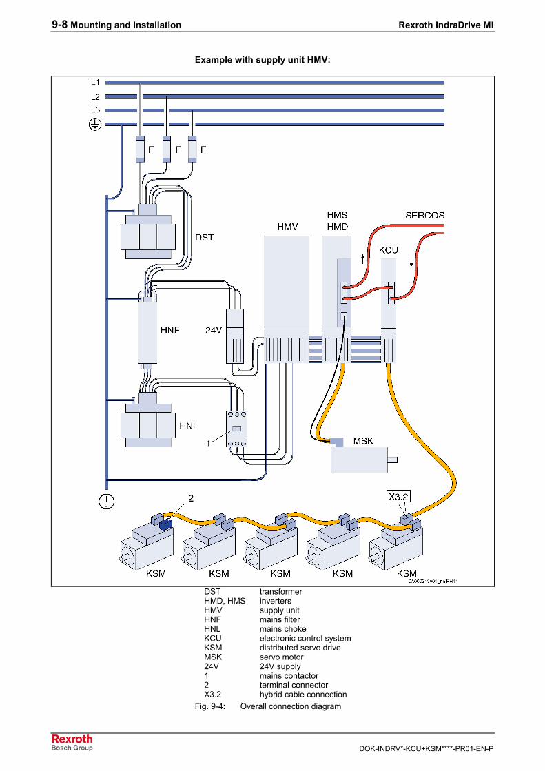
9-8 Mounting and Installation Rexroth IndraDrive Mi
DOK-INDRV*-KCU+KSM****-PR01-EN-P
Example with supply unit HMV:
DST transformerHMD, HMS invertersHMV supply unitHNF mains filterHNL mains chokeKCU electronic control systemKSM distributed servo driveMSK servo motor24V 24V supply1 mains contactor2 terminal connectorX3.2 hybrid cable connection
Fig. 9-4: Overall connection diagram
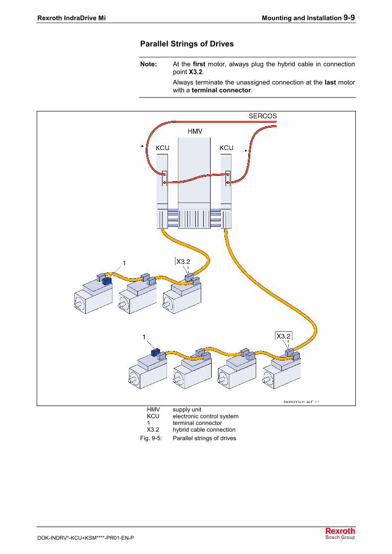
Rexroth IndraDrive Mi Mounting and Installation 9-9
DOK-INDRV*-KCU+KSM****-PR01-EN-P
Parallel Strings of Drives
Note: At the first motor, always plug the hybrid cable in connectionpoint X3.2.Always terminate the unassigned connection at the last motorwith a terminal connector.
HMV supply unitKCU electronic control system1 terminal connectorX3.2 hybrid cable connection
Fig. 9-5: Parallel strings of drives
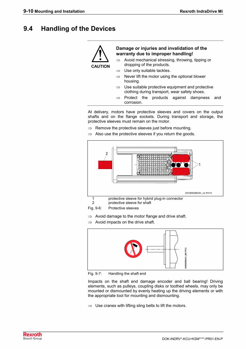
9-10 Mounting and Installation Rexroth IndraDrive Mi
DOK-INDRV*-KCU+KSM****-PR01-EN-P
9.4 Handling of the Devices
CAUTION
Damage or injuries and invalidation of thewarranty due to improper handling!⇒ Avoid mechanical stressing, throwing, tipping or
dropping of the products.⇒ Use only suitable tackles.⇒ Never lift the motor using the optional blower
housing.⇒ Use suitable protective equipment and protective
clothing during transport, wear safety shoes.⇒ Protect the products against dampness and
corrosion.
At delivery, motors have protective sleeves and covers on the outputshafts and on the flange sockets. During transport and storage, theprotective sleeves must remain on the motor.⇒ Remove the protective sleeves just before mounting.⇒ Also use the protective sleeves if you return the goods.
1 protective sleeve for hybrid plug-in connector2 protective sleeve for shaft
Fig. 9-6: Protective sleeves
⇒ Avoid damage to the motor flange and drive shaft.⇒ Avoid impacts on the drive shaft.
Fig. 9-7: Handling the shaft end
Impacts on the shaft end damage encoder and ball bearing! Drivingelements, such as pulleys, coupling disks or toothed wheels, may only bemounted or dismounted by evenly heating up the driving elements or withthe appropriate tool for mounting and dismounting.
⇒ Use cranes with lifting sling belts to lift the motors.
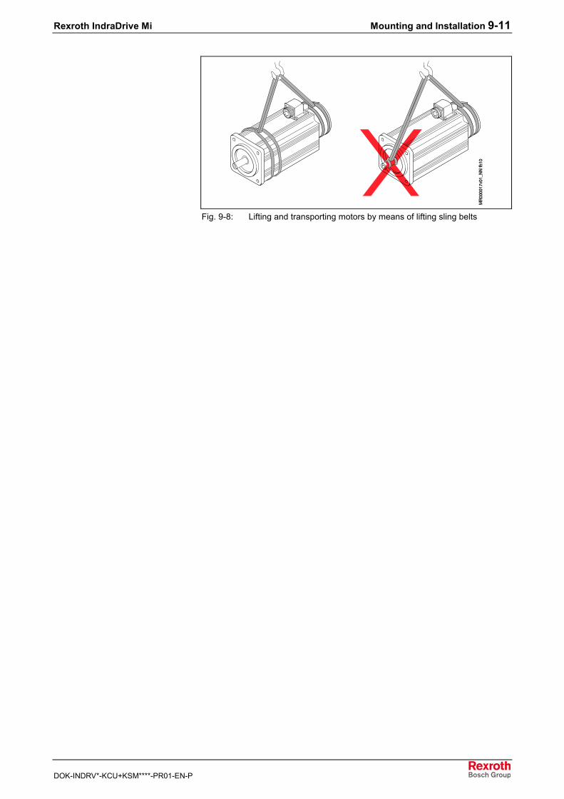
Rexroth IndraDrive Mi Mounting and Installation 9-11
DOK-INDRV*-KCU+KSM****-PR01-EN-P
Fig. 9-8: Lifting and transporting motors by means of lifting sling belts

9-12 Mounting and Installation Rexroth IndraDrive Mi
DOK-INDRV*-KCU+KSM****-PR01-EN-P
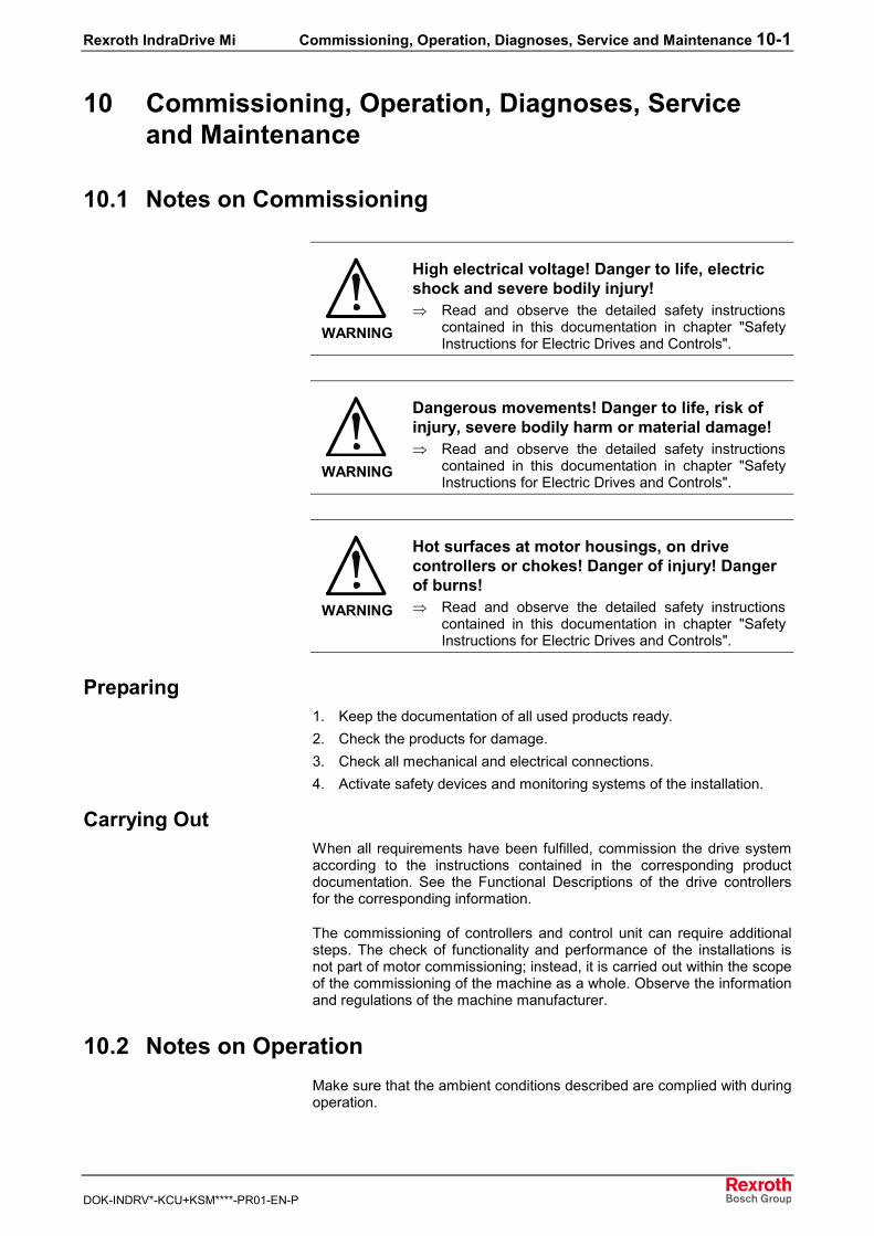
Rexroth IndraDrive Mi Commissioning, Operation, Diagnoses, Service and Maintenance 10-1
DOK-INDRV*-KCU+KSM****-PR01-EN-P
10 Commissioning, Operation, Diagnoses, Serviceand Maintenance
10.1 Notes on Commissioning
WARNING
High electrical voltage! Danger to life, electricshock and severe bodily injury!⇒ Read and observe the detailed safety instructions
contained in this documentation in chapter "SafetyInstructions for Electric Drives and Controls".
WARNING
Dangerous movements! Danger to life, risk ofinjury, severe bodily harm or material damage!⇒ Read and observe the detailed safety instructions
contained in this documentation in chapter "SafetyInstructions for Electric Drives and Controls".
WARNING
Hot surfaces at motor housings, on drivecontrollers or chokes! Danger of injury! Dangerof burns!⇒ Read and observe the detailed safety instructions
contained in this documentation in chapter "SafetyInstructions for Electric Drives and Controls".
Preparing1. Keep the documentation of all used products ready.2. Check the products for damage.3. Check all mechanical and electrical connections.4. Activate safety devices and monitoring systems of the installation.
Carrying OutWhen all requirements have been fulfilled, commission the drive systemaccording to the instructions contained in the corresponding productdocumentation. See the Functional Descriptions of the drive controllersfor the corresponding information.
The commissioning of controllers and control unit can require additionalsteps. The check of functionality and performance of the installations isnot part of motor commissioning; instead, it is carried out within the scopeof the commissioning of the machine as a whole. Observe the informationand regulations of the machine manufacturer.
10.2 Notes on OperationMake sure that the ambient conditions described are complied with duringoperation.
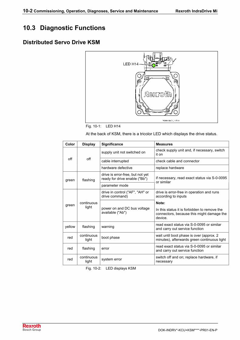
10-2 Commissioning, Operation, Diagnoses, Service and Maintenance Rexroth IndraDrive Mi
DOK-INDRV*-KCU+KSM****-PR01-EN-P
10.3 Diagnostic Functions
Distributed Servo Drive KSM
Fig. 10-1: LED H14
At the back of KSM, there is a tricolor LED which displays the drive status.
Color Display Significance Measures
supply unit not switched on check supply unit and, if necessary, switchit on
cable interrupted check cable and connectoroff off
hardware defective replace hardware
drive is error-free, but not yetready for drive enable ("Bb")green flashingparameter mode
if necessary, read exact status via S-0-0095or similar
drive in control ("AF", "AH" ordrive command)
green continuouslight power on and DC bus voltage
available ("Ab")
drive is error-free in operation and runsaccording to inputs
Note:
In this status it is forbidden to remove theconnectors, because this might damage thedevice.
yellow flashing warning read exact status via S-0-0095 or similarand carry out service function
red continuouslight boot phase wait until boot phase is over (approx. 2
minutes), afterwards green continuous light
red flashing error read exact status via S-0-0095 or similarand carry out service function
red continuouslight system error switch off and on; replace hardware, if
necessary
Fig. 10-2: LED displays KSM
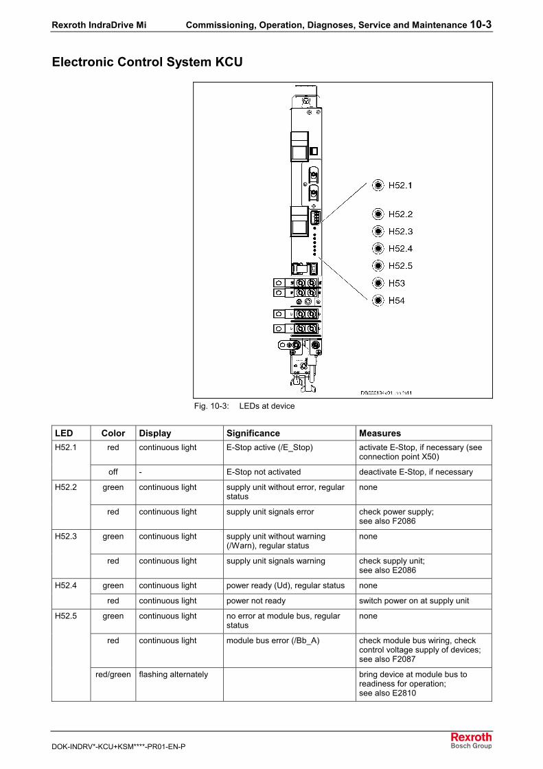
Rexroth IndraDrive Mi Commissioning, Operation, Diagnoses, Service and Maintenance 10-3
DOK-INDRV*-KCU+KSM****-PR01-EN-P
Electronic Control System KCU
Fig. 10-3: LEDs at device
LED Color Display Significance Measuresred continuous light E-Stop active (/E_Stop) activate E-Stop, if necessary (see
connection point X50)H52.1
off - E-Stop not activated deactivate E-Stop, if necessary
green continuous light supply unit without error, regularstatus
noneH52.2
red continuous light supply unit signals error check power supply;see also F2086
green continuous light supply unit without warning(/Warn), regular status
noneH52.3
red continuous light supply unit signals warning check supply unit;see also E2086
green continuous light power ready (Ud), regular status noneH52.4
red continuous light power not ready switch power on at supply unit
green continuous light no error at module bus, regularstatus
none
red continuous light module bus error (/Bb_A) check module bus wiring, checkcontrol voltage supply of devices;see also F2087
H52.5
red/green flashing alternately bring device at module bus toreadiness for operation;see also E2810
10-4 Commissioning, Operation, Diagnoses, Service and Maintenance Rexroth IndraDrive Mi
DOK-INDRV*-KCU+KSM****-PR01-EN-P
LED Color Display Significance Measuresgreen continuous light voltage at output X53 ok noneH53
red continuous light voltage at output X53 not ok overload at output: check voltageat X53, reduce load; remove shortcircuit
green continuous light output voltage at X54 ok(U > 50 V)
none
red continuous light output voltage at X54 not ok check fuses F4, F5
H54
off - DC bus (L+, L-) not ready forpower output
Voltage at X54 is only monitored, ifpower ready (see LED H52.4)
Fig. 10-4: LED displays KCU
Diagnostic Messages via ParametersThe usual IndraDrive diagnostic parameters are used:• S-0-0095• S-0-0390• P-0-0009• …
See also documentation Parameter Description of firmware
Firmware Functions
"Easy Startup" ModeThe "easy startup mode" intended for initial commissioning can beactivated in conjunction with Rexroth IndraWorks D at X2. This activatesthe following digital inputs:• I_1 (X37.4): +24 V to activate positive direction of rotation• I_2 (X37.2): +24 V to activate negative direction of rotation• I_3 (X38.4): +24 V to activate drive enable
Oscilloscope FunctionYou can use the integrated oscilloscope function described in theFunctional Description!See also Functional Description of firmware chapter "Handling, Diagnosticand Service Functions / Oscilloscope Function"
Analog Outputs
Note: Rexroth IndraDrive Mi has no analog outputs!
Patch FunctionThe distributed servo drive KSM has a function which allows reading orwriting controller-internal memory cells.See also Functional Description of firmware chapter "Handling, Diagnosticand Service Functions / Extended Diagnostic Possibilities / PatchFunction"
Rexroth IndraDrive Mi Commissioning, Operation, Diagnoses, Service and Maintenance 10-5
DOK-INDRV*-KCU+KSM****-PR01-EN-P
Monitoring FunctionFor extended diagnostic possibilities, the distributed servo drive has amonitoring function.See also Functional Description of firmware chapter "Handling, Diagnosticand Service Functions / Extended Diagnostic Possibilities / MonitoringFunction"
10.4 Service Functions/TroubleshootingThe following section explains the subfunctions required to eliminateerrors or malfunction. We distinguish the following actions:• deactivation• dismounting• motor replacement
Deactivating and Dismounting the Drive
DeactivationIn the case of malfunction, maintenance measures or to deactivate themotors, proceed as follows:1. Observe the instructions contained in the machine documentation.2. Use the machine-side control commands to bring the drive to a
controlled standstill.3. Switch off the power voltage and control voltage of the controller.4. Switch off the main switch of the machine.5. Secure the machine against accidental movements and against
unauthorized operation.6. Wait to allow the electric systems to discharge and then disconnect
all electrical connections.7. Before dismounting them, secure the motor and, if necessary, the
blower unit against falling or movements, before unfastening themechanical connections.
Dismounting
DANGER
Lethal injury caused by errors when controllingmotors and working at moving parts!⇒ Do not work at running or unsecured installations.⇒ Before starting to dismount, secure the machine
against accidental movements and unauthorizedoperation.
⇒ Before dismounting them, secure the motor and thesupply lines unit against falling or movements, beforeunfastening the mechanical connections.
10-6 Commissioning, Operation, Diagnoses, Service and Maintenance Rexroth IndraDrive Mi
DOK-INDRV*-KCU+KSM****-PR01-EN-P
WARNING
Burns caused by hot surfaces withtemperatures of more than 100 °C!⇒ Before beginning to work, let the motors cool down.
The thermal time constant specified in the TechnicalData is a measure for the time required for coolingdown. Cooling down can require up to 140 minutes!
⇒ Do not work at hot surfaces.⇒ Wear safety gloves.
1. Observe the instructions contained in the machine documentation.2. Observe the Safety Instructions and carry out all steps according to
the above instructions for "deactivation".3. Before dismounting them, secure the motor and the supply lines unit
against falling or movements, before unfastening the mechanicalconnections.
4. Dismount the motor from the machine.5. Store the motor appropriately.
Replacing KSMIn case servicing becomes necessary, the motor with electronic system isreplaced by a new motor of the same type. This requires the followingsteps:1. De-energize the machine (switch 24V off, too!).
DANGER
Lethal electric shock caused by live parts withmore than 50 V!⇒ Wait to allow the DC bus capacitors to discharge or
use discharging device for DC bus.
2. Wait 30 minutes to allow the DC bus capacitors to discharge or usedischarging device for DC bus (see chapter "Discharging of DC BusCapacitors" in Appendix).
3. Ensure isolation from supply.4. Dismount the defective motor.5. Remove the MMC from the defective motor at X7.6. Set the SERCOS address at the new motor.7. Plug the removed MMC into the new motor and mount the cover,
make sure the sealing ring is undamaged.8. Mount the new motor and establish the electrical connections.9. Switch on 24V supply.10. Load the parameter set.11. Reestablish the position data reference (homing procedure).
Rexroth IndraDrive Mi Commissioning, Operation, Diagnoses, Service and Maintenance 10-7
DOK-INDRV*-KCU+KSM****-PR01-EN-P
Service Function "Release Holding Brake"Via the interface X2 at KSM, you can "release" the integrated holdingbrake.
DANGER
Lethal injury caused by errors when controllingmotors and working at moving parts!⇒ Do not work at running or unsecured installations.⇒ Before starting to dismount, secure the machine
against accidental movements and unauthorizedoperation.
⇒ Before dismounting them, secure the motor and thesupply lines unit against falling or movements, beforeunfastening the mechanical connections.
For the purpose of commissioning and servicing, release the holdingbrake via connection point X2 by connecting the contacts X2.1 and X2.2.
Saving ParametersFor servicing, the drive parameters must be saved and archived at initialcommissioning (e.g. with Rexroth IndraWorks D); this is necessary,because you won't probably be able to read the parameters of thedefective drive.Parameters can be administrated in the control unit or saved and loadedvia the RS232 interface (X2) and Rexroth IndraWorks D.
Firmware UpdateSee Functional Description of firmware.
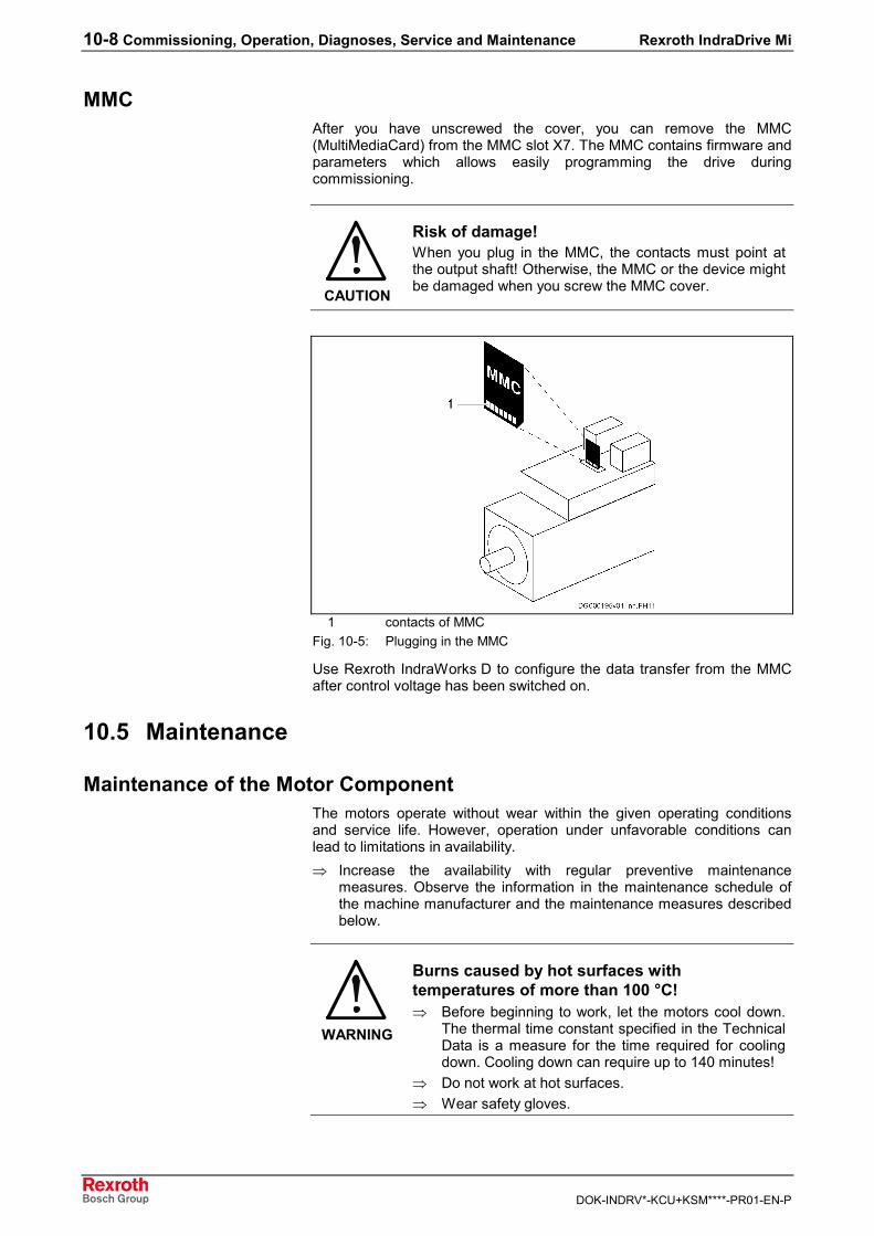
10-8 Commissioning, Operation, Diagnoses, Service and Maintenance Rexroth IndraDrive Mi
DOK-INDRV*-KCU+KSM****-PR01-EN-P
MMCAfter you have unscrewed the cover, you can remove the MMC(MultiMediaCard) from the MMC slot X7. The MMC contains firmware andparameters which allows easily programming the drive duringcommissioning.
CAUTION
Risk of damage!When you plug in the MMC, the contacts must point atthe output shaft! Otherwise, the MMC or the device mightbe damaged when you screw the MMC cover.
1 contacts of MMCFig. 10-5: Plugging in the MMC
Use Rexroth IndraWorks D to configure the data transfer from the MMCafter control voltage has been switched on.
10.5 Maintenance
Maintenance of the Motor ComponentThe motors operate without wear within the given operating conditionsand service life. However, operation under unfavorable conditions canlead to limitations in availability.⇒ Increase the availability with regular preventive maintenance
measures. Observe the information in the maintenance schedule ofthe machine manufacturer and the maintenance measures describedbelow.
WARNING
Burns caused by hot surfaces withtemperatures of more than 100 °C!⇒ Before beginning to work, let the motors cool down.
The thermal time constant specified in the TechnicalData is a measure for the time required for coolingdown. Cooling down can require up to 140 minutes!
⇒ Do not work at hot surfaces.⇒ Wear safety gloves.
Rexroth IndraDrive Mi Commissioning, Operation, Diagnoses, Service and Maintenance 10-9
DOK-INDRV*-KCU+KSM****-PR01-EN-P
WARNING
Danger of injury due to moving elements!⇒ Do not carry out any maintenance measures at
running machines.⇒ During maintenance work, secure the installation
against restart and unauthorized use.
CleaningExcessive dirt, dust or shavings may affect the function of the motorsadversely, may in extreme cases even cause a failure of the motors. Forthat reason, you should clean the cooling ribs of the motors in regularintervals (at the latest, after one year is over).
BearingThe nominal service life of the bearings is L10h > 30000 h according toDIN ISO 281, ed. 1990, if the permissible radial and axial forces are notexceeded.The motor bearings should be replaced, if• the nominal bearing service life has been reached,• running noise can be heard.
Note: We recommend that you have the bearings replaced by theBosch Rexroth service.
Connection CablesCheck connection cables for damage in regular intervals and replacethem, if necessary.Check any optionally present energy management chains (drag chains fordamage.
DANGER
Lethal electric shock caused by live parts withmore than 50 V!⇒ Do not repair any connection lines provisionally. If
the slightest damage is detected in the cable sheath,the installation must be put out of operationimmediately. Then the cable must be replaced.
Check the connection of equipment grounding conductor for proper statusand tight fit in regular intervals.
Holding BrakeIn order to ensure proper functioning of the holding brake, it must bechecked before the motors are installed.
Measure the holding torque of the brake; abrade the holding brake, ifnecessary.
Proceed as follows:1. De-energize the motor and secure it against re-energization.2. Measure the transmittable holding torque of the holding brake using a
torque wrench. The holding torque of the brakes is specified in thedata sheets.
Before Initial Commissioning
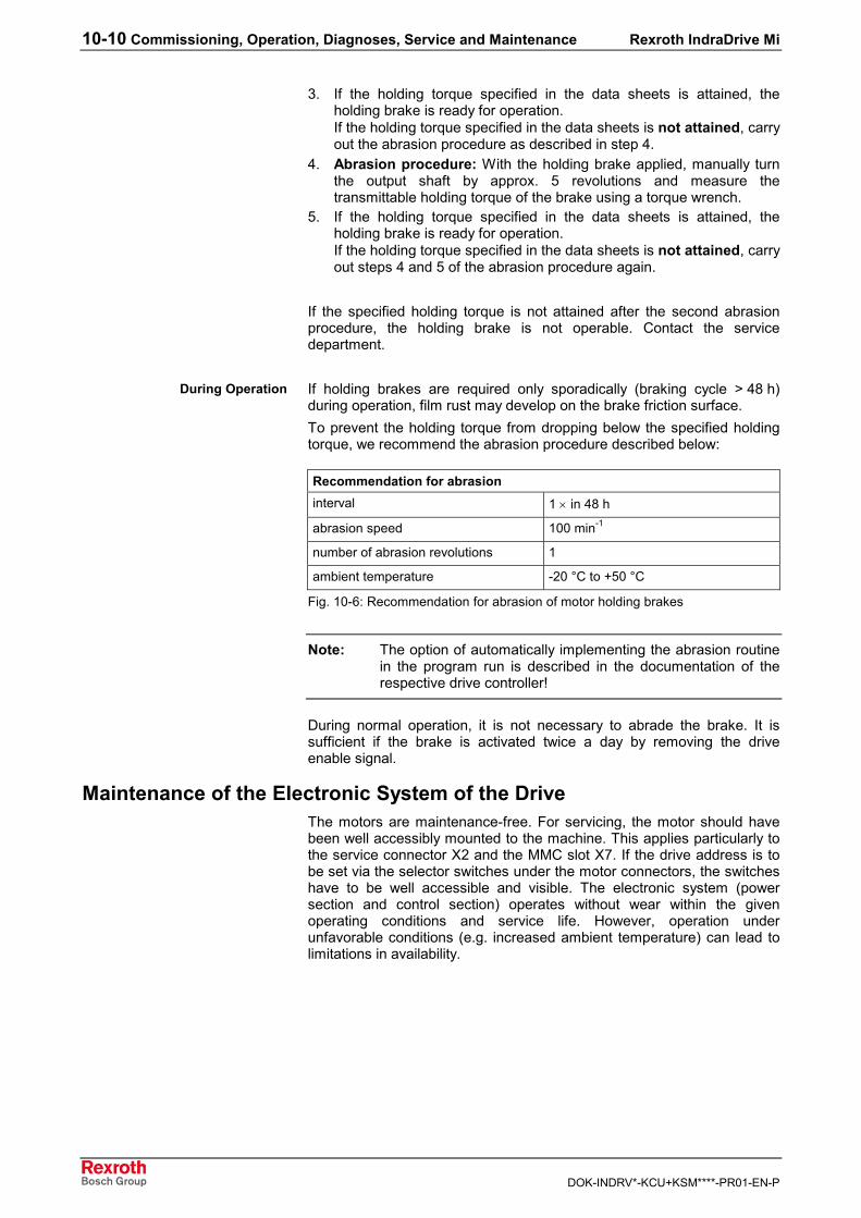
10-10 Commissioning, Operation, Diagnoses, Service and Maintenance Rexroth IndraDrive Mi
DOK-INDRV*-KCU+KSM****-PR01-EN-P
3. If the holding torque specified in the data sheets is attained, theholding brake is ready for operation.If the holding torque specified in the data sheets is not attained, carryout the abrasion procedure as described in step 4.
4. Abrasion procedure: With the holding brake applied, manually turnthe output shaft by approx. 5 revolutions and measure thetransmittable holding torque of the brake using a torque wrench.
5. If the holding torque specified in the data sheets is attained, theholding brake is ready for operation.If the holding torque specified in the data sheets is not attained, carryout steps 4 and 5 of the abrasion procedure again.
If the specified holding torque is not attained after the second abrasionprocedure, the holding brake is not operable. Contact the servicedepartment.
If holding brakes are required only sporadically (braking cycle > 48 h)during operation, film rust may develop on the brake friction surface.To prevent the holding torque from dropping below the specified holdingtorque, we recommend the abrasion procedure described below:
Recommendation for abrasioninterval 1 × in 48 h
abrasion speed 100 min-1
number of abrasion revolutions 1
ambient temperature -20 °C to +50 °C
Fig. 10-6: Recommendation for abrasion of motor holding brakes
Note: The option of automatically implementing the abrasion routinein the program run is described in the documentation of therespective drive controller!
During normal operation, it is not necessary to abrade the brake. It issufficient if the brake is activated twice a day by removing the driveenable signal.
Maintenance of the Electronic System of the DriveThe motors are maintenance-free. For servicing, the motor should havebeen well accessibly mounted to the machine. This applies particularly tothe service connector X2 and the MMC slot X7. If the drive address is tobe set via the selector switches under the motor connectors, the switcheshave to be well accessible and visible. The electronic system (powersection and control section) operates without wear within the givenoperating conditions and service life. However, operation underunfavorable conditions (e.g. increased ambient temperature) can lead tolimitations in availability.
During Operation
Rexroth IndraDrive Mi Disposal and Environmental Protection 11-1
DOK-INDRV*-KCU+KSM****-PR01-EN-P
11 Disposal and Environmental Protection
11.1 Disposal
ProductsOur products can be returned to us free of charge for disposal. It is aprecondition, however, that the products are free of oil, grease or otherdirt.Furthermore, the products returned for disposal must not contain anyundue foreign matter or foreign component.Please send the products free domicile to the following address:Bosch Rexroth AGElectric Drives and ControlsBürgermeister-Dr.-Nebel-Straße 2D-97816 Lohr am Main
Packaging MaterialsThe packaging materials consist of cardboard, wood and polystyrene.These materials can be easily recycled in any municipal recycling system.For ecological reasons, please refrain from returning the empty packagesto us.
11.2 Environmental Protection
No Release of Hazardous SubstancesOur products do not contain any hazardous substances which may bereleased in the case of appropriate use. Accordingly, our products willnormally not have any negative effect on the environment.
Materials Contained in the Products
Electronic DevicesElectronic devices mainly contain:• steel• aluminum• copper• synthetic materials• electronic components and modules
MotorsMotors mainly contain:• steel• aluminum• copper• brass• magnetic materials• electronic components and modules
11-2 Disposal and Environmental Protection Rexroth IndraDrive Mi
DOK-INDRV*-KCU+KSM****-PR01-EN-P
RecyclingDue to their high content of metal, most of the product components canbe recycled. In order to recycle the metal in the best possible way, theproducts must be disassembled into individual modules.Metals contained in electric and electronic modules can also be recycledby means of special separation processes. The synthetic materialsremaining after these processes can be thermally recycled.If the products contain batteries or accumulators, these have to beremoved before recycling and disposed of.
Rexroth IndraDrive Mi Appendix 12-1
DOK-INDRV*-KCU+KSM****-PR01-EN-P
12 Appendix
12.1 Discharging of DC Bus CapacitorsIn the drive system Rexroth IndraDrive, capacitors are used in the DC busas energy stores. In the drive controllers and particularly in the supplyunits, such capacitors have already been integrated.Energy stores maintain their energy even when energy supply has beencut off and have to be discharged before somebody gets in contact withthem.Discharging devices have been integrated in the components of the drivesystem Rexroth IndraDrive; within the indicated discharging time, thesedevices discharge the voltage below the allowed 50 V.If additional capacitances in the form of• DC bus capacitor units or• additional capacitorsare connected, make sure that these capacitors, too, are dischargedbefore somebody gets in contact with them.
Due to the operating principle, the discharging time is the longer• the bigger the energy store (the capacitance value)• the higher the voltage to which the energy store has been charged• the greater the resistance for discharging the capacitors.
Components of the drive system Rexroth IndraDrive have beendimensioned in such a way that after the energy supply was cut off thevoltage value falls below 50 V within a discharging time of a maximum of30 minutes.
WARNING
Lethal electric shock caused by live parts withmore than 50 V!⇒ Wait at least 30 minutes after switching off power to
allow discharging.⇒ Check whether voltage has fallen below 50 V before
touching live parts!
To shorten the waiting time until voltage has fallen below 50 V, you cantake the following measures:• Activate the function "ZKS" (DC bus short circuit) when using HMV01
supply units.• Use the discharging device described below.
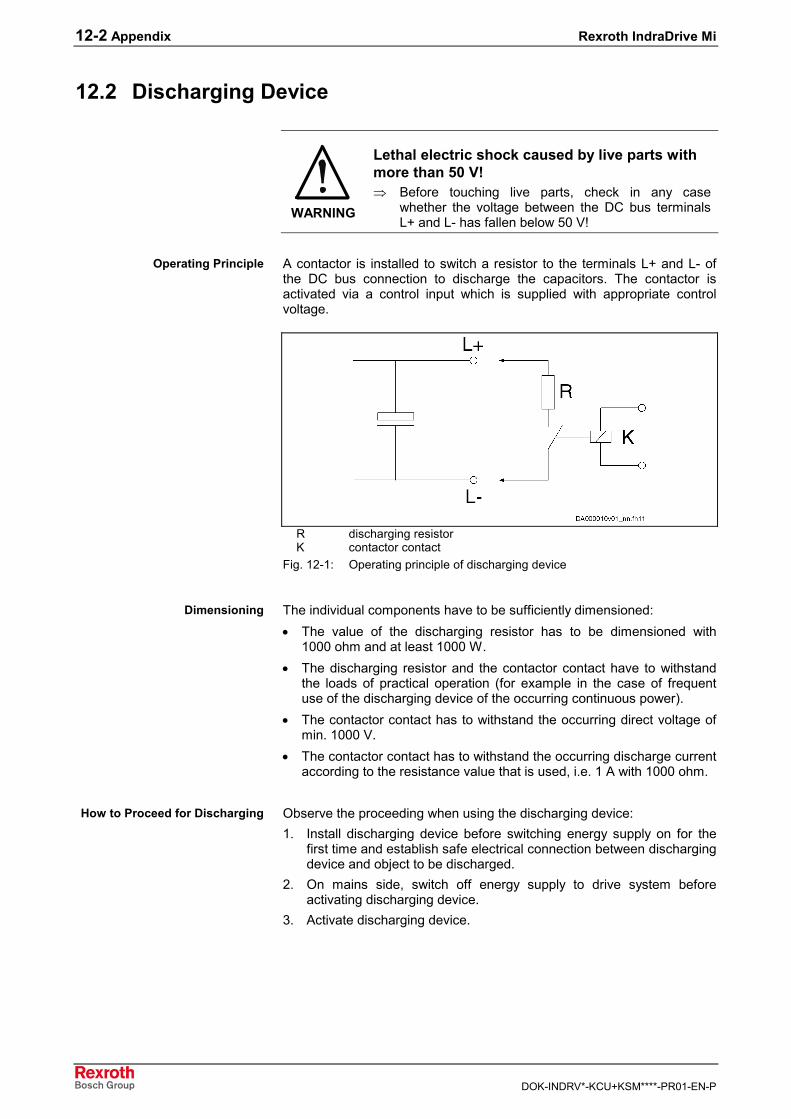
12-2 Appendix Rexroth IndraDrive Mi
DOK-INDRV*-KCU+KSM****-PR01-EN-P
12.2 Discharging Device
WARNING
Lethal electric shock caused by live parts withmore than 50 V!⇒ Before touching live parts, check in any case
whether the voltage between the DC bus terminalsL+ and L- has fallen below 50 V!
A contactor is installed to switch a resistor to the terminals L+ and L- ofthe DC bus connection to discharge the capacitors. The contactor isactivated via a control input which is supplied with appropriate controlvoltage.
R discharging resistorK contactor contact
Fig. 12-1: Operating principle of discharging device
The individual components have to be sufficiently dimensioned:• The value of the discharging resistor has to be dimensioned with
1000 ohm and at least 1000 W.• The discharging resistor and the contactor contact have to withstand
the loads of practical operation (for example in the case of frequentuse of the discharging device of the occurring continuous power).
• The contactor contact has to withstand the occurring direct voltage ofmin. 1000 V.
• The contactor contact has to withstand the occurring discharge currentaccording to the resistance value that is used, i.e. 1 A with 1000 ohm.
Observe the proceeding when using the discharging device:1. Install discharging device before switching energy supply on for the
first time and establish safe electrical connection between dischargingdevice and object to be discharged.
2. On mains side, switch off energy supply to drive system beforeactivating discharging device.
3. Activate discharging device.
Operating Principle
Dimensioning
How to Proceed for Discharging
Rexroth IndraDrive Mi Service and Support 13-1
DOK-INDRV*-KCU+KSM****-PR01-EN-P
13 Service and Support
13.1 HelpdeskOur service helpdesk at our headquarters in Lohr, Germany, will assistyou with all kinds of enquiries.
Phone +49 (0) 9352 40 50 60 Call Entry CenterMo–Fr 7.00–18.00 UhrCentral European Time
Fax +49 (0) 9352 40 49 41
E-Mail [email protected]
13.2 Service HotlineOut of helpdesk hours please contact our German service departmentdirectly:
Phone +49 (0) 171 333 88 26 or
+49 (0) 172 660 04 06
Hotline numbers for other countries can be found in the addresses ofeach region (see below).
13.3 InternetAdditional notes regarding service, maintenance and training, as well asthe current addresses of our sales and service offices can be found on
Internet http://www.boschrexroth.com
Outwith Germany please contact our sales/service office in your area first.
13.4 Helpful InformationFor quick and efficient help please have the following information ready:• Detailed description of the fault and the circumstances• Information on the type plate of the affected products, especially type
codes and serial numbers• Your phone and fax numbers as well as your e-mail address so we
can contact you in case of questions

13-2 Service and Support Rexroth IndraDrive Mi
DOK-INDRV*-KCU+KSM****-PR01-EN-P
Rexroth IndraDrive Mi Index 14-1
DOK-INDRV*-KCU+KSM****-PR01-EN-P
14 Index
++24V, 0V
Control voltage supply connection 6-11
224V control voltage 7-1124V supply 7-13
AAccessory
HAS01 6-9HAS02.1-015-NNN-NN 6-12HAS03 6-10Shield connection 6-12Strain relief 6-12
Address selector switchSERCOS 7-14
Ambient conditions 4-2Analog outputs 10-4Appropriate use 2-1Average speed 7-3Axial load 7-3
BBearings
Load 5-12, 7-3Maintenance 10-9Redundant 7-8Service life 7-4Wear 7-4
Brake control 7-5Braking energy 7-7
CCables
Allowed lengths 7-10Allowed lengths vs. number of axes 7-12Maintenance 10-9Selection 5-17Technical data 5-17
Capacity utilization 4-5CE label 4-1Certifications 4-1Characteristics
KSM 5-7Cleaning 10-9Commissioning 10-1Compatibility
With foreign matters 4-4Components
General specification 4-1Rexroth IndraDrive Mi 1-2
ConditionsAmbient 4-2Installation 4-2Operation 4-2Storage 4-2Transport 4-2
ConnectionAccessory 6-12
14-2 Index Rexroth IndraDrive Mi
DOK-INDRV*-KCU+KSM****-PR01-EN-P
Connection diagram drive system 9-7Connection diagram KCU 9-3Connection points KCU 6-3Connection points KSM 6-13Control voltage supply 6-11DC bus 6-9Electrical 9-6Equipment grounding conductor 6-1Ground 6-2Hybrid cable 6-15
Connection diagramDrive system 9-7KCU 9-3
Connection pointsKCU 6-3KSM 6-13
Contact bars 6-10Control voltage 7-11Control voltage output
X53 6-7Control voltage supply
Connection 6-11Cooling mode 1-7Cooling ribs 10-9Coupling attachment 7-9C-UL-US listing 4-1Current limitation 7-15Cycle duration 5-3
DDC bus
Connection 6-9DC bus output
X54 6-8Deactivation 10-5Declarations of conformity 4-1Diagnosis
Functions 10-2LEDs 10-2Parameters 10-4
Dimensional drawingKCU 5-16KSM 5-10
DimensionsKCU 5-16KSM 5-10
Dismounting 10-5Disposal 11-1Distortion indicator 7-14Distributed servo drive KSM 1-1Documentation structure 1-10Documentations
Overview 1-10Drive system
Connection diagram 9-7Driving elements 7-8
EEasy startup mode 10-4Electrical connection 9-6Electronic control system KCU 1-1, 5-14
Notes on project planning 7-13Environmental protection 11-1Equipment grounding conductor
Connection 6-1E-Stop
Input 6-6
Rexroth IndraDrive Mi Index 14-3
DOK-INDRV*-KCU+KSM****-PR01-EN-P
FF4 6-3F5 6-3Failure of bearing 7-4Firmware 1-9
Functions 10-4Update 10-7
Foreign mattersCompatibility 4-4
FuseF4 6-3F5 6-3
GGear attachment 7-8Grease
Service life 7-4Ground connection 6-2
Additional, KSM 6-20
HH14 10-2H52.1…H54 10-3Handling
Of the devices 9-10HAS01 6-9HAS02.1-015-NNN-NN 6-12HAS03 6-10HCS
As supply unit 7-13Heat dissipation 10-9Helpdesk 13-1Holding brake 1-8
Abrasion 10-10Clamping delay 7-5Commissioning 10-9Control 7-5Danger warning 7-6Release delay 7-5
Housing overtemperature 5-3Housing varnish 4-4Hybrid cables 1-2
Allowed lengths 7-10Allowed lengths vs. number of axes 7-12Between KCU and first motor 5-19Between two motors 5-20Connection 6-15Interconnection diagrams 5-19Outgoing direction 5-17RKH 5-17Selection 5-17Technical data 5-17
IIdentification 8-1Idle time 5-3Inappropriate use 2-2Inputs
Isolated 6-17Inrush current 24V supply 7-14Installation 9-6Installation conditions 4-2Interconnection diagrams
Hybrid cables 5-19Interface
serial 6-14
14-4 Index Rexroth IndraDrive Mi
DOK-INDRV*-KCU+KSM****-PR01-EN-P
InterfacesElectrical 9-7
Internet 13-1Isolated inputs/outputs 6-17
KKCU 1-1
Applications 5-14Brief description 5-14Connection diagram 9-3Connection points 6-3Dimensional drawing 5-16Dimensions 5-16LED H52.1…H54 10-3Notes on project planning 7-13Scope of supply 8-1Technical data 5-14Type code 1-9Type plate 8-3
Key 7-1KSM 1-1
Additional ground connection 6-20Bearings load 5-12Characteristics 5-7Connection points 6-13Data sheet 5-5Dimensional drawing 5-10Dimensions 5-10H14 10-2Parallel strings 9-9Replacement 10-6Scope of supply 8-1Shaft load 5-12Technical data 5-5Technical design 5-10Type code 1-6Type plate 8-1
LL+, L- 6-9LED
H14 10-2H52.1…H54 10-3KCU 10-3
Length 1-7Lifting sling belts 9-10Limitation
Motor current 7-15Load
Bearings and shaft 7-3
MMaintenance 10-8Master communication 1-8Materials
Contained 11-1Mechanical interfaces 9-5MMC 6-16, 10-8Module bus 6-4Motor blower 7-15Motor current
Limitation 7-15Motor encoder (encoder system) 1-7Motor temperature 7-16Mounting
Mechanical interfaces 9-5Practical tips 9-4
Rexroth IndraDrive Mi Index 14-5
DOK-INDRV*-KCU+KSM****-PR01-EN-P
Required steps to follow 9-4Mounting clearance 7-1Mounting depth 6-10Mounting positions 4-4Mounting the flange 9-5MultiMediaCard 6-16, 10-8
NNotes on operation 10-1Number of axes
Maximum 7-10
OON time 5-3Operating conditions 4-2Operating modes 5-3Oscilloscope function 10-4Outgoing direction
Hybrid cables 5-17Output shaft
Plain output shaft 1-7, 7-1Shaft with keyway 1-7
OutputsIsolated 6-17
Overview of functions 1-5
PPackaging materials 11-1Parallel strings of drives 9-9Parameters
Save 10-7PFM02 6-16Pinions 7-9PN3 5-14Power supply 7-13Power supply unit
24V 7-11Prime coat 4-4Probe 6-17Processing cycle 7-4Product presentation 1-1Project planning
Notes 7-1Protective sleeves 9-10
QQualified technical staff 9-1
RRadial load 7-3Radial shaft sealing ring 7-2Recycling 11-2Redundant bearings 7-8Release brake 6-14Replacement
KSM 10-6Rexroth IndraDrive Mi
Components 1-2Features 1-1
Rexroth IndraDyn 1-2RKH 5-17RS232 6-14Running noise 10-9
14-6 Index Rexroth IndraDrive Mi
DOK-INDRV*-KCU+KSM****-PR01-EN-P
SS4, S5
SERCOS address selector switch 7-14S6 6-5Safety instructions for electric drives 3-1Safety option 1-8Scope of supply
KCU 8-1KSM 8-1
Sealing ring 7-2SERCOS
Address selector switch 7-14Interface 6-5Transmission power switch S6 6-5X51 6-6
Serial interface X2 6-14Service
Hotline 13-1Service input
X2 6-14Shaft 1-7
Load 5-12, 7-3Plain 7-1Sealing ring 7-2With key 7-1
Shield connection 6-12Size 1-7Specification
General 4-1Status messages
X52 6-7Storage
Conditions 4-2Strain relief 6-12Strings of drives
Parallel 9-9Substances
Release 11-1Supply unit
HCS 7-13HMV 7-13
Support 13-1Switching frequency 7-16System presentation 1-1System Structure 1-3
TTechnical data
Cables 5-17Hybrid cables 5-17KCU 5-14KSM 5-5Motor 5-3Terms and definitions 5-1
TemperatureMotor 7-16
Terminal connector 5-21Torque-speed characteristic
Operation characteristic S1 5-4Transport
Conditions 4-2Troubleshooting 10-5Type code
KCU 1-9KSM 1-6
Type plateKCU 8-3KSM 8-1
Types of construction 4-4
Rexroth IndraDrive Mi Index 14-7
DOK-INDRV*-KCU+KSM****-PR01-EN-P
Types of installation 4-4
UUL listing 4-1UN3 5-14Use
Appropriate use 2-1
VVarnish 4-4
WWinding 1-7
XX1 6-4X2 6-14X20 TX 6-5X21 RX 6-5X3.1, X3.2 6-15X37, X38 6-17X50 6-6X51 6-6X52 6-7X53 6-7X54 6-8X7 6-16

14-8 Index Rexroth IndraDrive Mi
DOK-INDRV*-KCU+KSM****-PR01-EN-P

Bosch Rexroth AGElectric Drives and ControlsP.O. Box 13 5797803 Lohr, GermanyBgm.-Dr.-Nebel-Str. 297816 Lohr, GermanyPhone +49 (0)93 52-40-50 60Fax +49 (0)93 52-40-49 [email protected]
Printed in GermanyDOK- INDRV*KCU+KSM****-PR01-EN-PR911320924