Rexroth IndraDrive Edition 01 Supply Units HMV01 · Rexroth IndraDrive Supply Units HMV01 Bosch...
84
Operating Instructions Electric Drives and Controls Pneumatics Service Linear Motion and Assembly Technologies Hydraulics Rexroth IndraDrive Supply Units HMV01 R911339050 Edition 01
-
Upload
vuonghuong -
Category
Documents
-
view
270 -
download
0
Transcript of Rexroth IndraDrive Edition 01 Supply Units HMV01 · Rexroth IndraDrive Supply Units HMV01 Bosch...
Operating Instructions
Electric Drivesand Controls Pneumatics Service
Linear Motion and Assembly TechnologiesHydraulics
Rexroth IndraDriveSupply UnitsHMV01
R911339050Edition 01
Rexroth IndraDriveSupply UnitsHMV01
Operating Instructions
DOK-INDRV*-HMV01******-IT01-EN-P
RS-27e36f9643172cb90a6846a50148dd42-1-en-US-2
Purpose of Documentation This documentation provides information on the installation and operation ofthe described products, by persons trained and qualified to work with electri‐cal installations.
Copyright © Bosch Rexroth AG 2013This document, as well as the data, specifications and other information setforth in it, are the exclusive property of Bosch Rexroth AG. It may not be re‐produced or given to third parties without its consent.
Liability The specified data is intended for product description purposes only and shallnot be deemed to be a guaranteed characteristic unless expressly stipulatedin the contract. All rights are reserved with respect to the content of this docu‐mentation and the availability of the product.
Published by Bosch Rexroth AGBgm.-Dr.-Nebel-Str. 2 ■ 97816 Lohr a. Main, GermanyPhone +49 9352 18 0 ■ Fax +49 9352 18 8400http://www.boschrexroth.com/DC-IA/EDY4 (CR)
Title
Type of Documentation
Document Typecode
Internal File Reference
Bosch Rexroth AG DOK-INDRV*-HMV01******-IT01-EN-P Rexroth IndraDrive Supply Units HMV01
Deutsch English Français
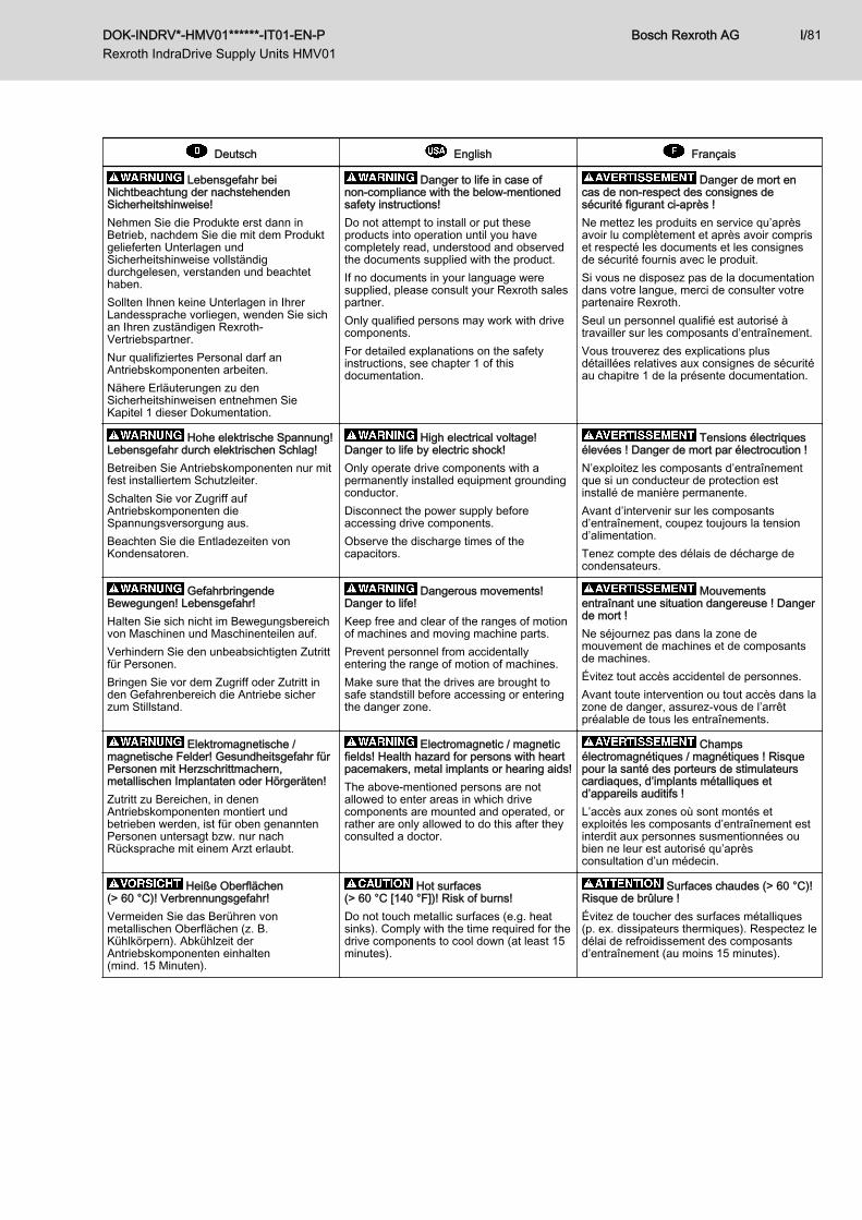
Lebensgefahr beiNichtbeachtung der nachstehendenSicherheitshinweise!Nehmen Sie die Produkte erst dann inBetrieb, nachdem Sie die mit dem Produktgelieferten Unterlagen undSicherheitshinweise vollständigdurchgelesen, verstanden und beachtethaben.Sollten Ihnen keine Unterlagen in IhrerLandessprache vorliegen, wenden Sie sichan Ihren zuständigen Rexroth-Vertriebspartner.Nur qualifiziertes Personal darf anAntriebskomponenten arbeiten.Nähere Erläuterungen zu denSicherheitshinweisen entnehmen SieKapitel 1 dieser Dokumentation.
Danger to life in case ofnon‑compliance with the below-mentionedsafety instructions!Do not attempt to install or put theseproducts into operation until you havecompletely read, understood and observedthe documents supplied with the product.If no documents in your language weresupplied, please consult your Rexroth salespartner.Only qualified persons may work with drivecomponents.For detailed explanations on the safetyinstructions, see chapter 1 of thisdocumentation.
Danger de mort encas de non‑respect des consignes desécurité figurant ci-après !Ne mettez les produits en service qu’aprèsavoir lu complètement et après avoir compriset respecté les documents et les consignesde sécurité fournis avec le produit.Si vous ne disposez pas de la documentationdans votre langue, merci de consulter votrepartenaire Rexroth.Seul un personnel qualifié est autorisé àtravailler sur les composants d’entraînement.Vous trouverez des explications plusdétaillées relatives aux consignes de sécuritéau chapitre 1 de la présente documentation.
Hohe elektrische Spannung!Lebensgefahr durch elektrischen Schlag!Betreiben Sie Antriebskomponenten nur mitfest installiertem Schutzleiter.Schalten Sie vor Zugriff aufAntriebskomponenten dieSpannungsversorgung aus.Beachten Sie die Entladezeiten vonKondensatoren.
High electrical voltage!Danger to life by electric shock!Only operate drive components with apermanently installed equipment groundingconductor.Disconnect the power supply beforeaccessing drive components.Observe the discharge times of thecapacitors.
Tensions électriquesélevées ! Danger de mort par électrocution !N’exploitez les composants d’entraînementque si un conducteur de protection estinstallé de manière permanente.Avant d’intervenir sur les composantsd’entraînement, coupez toujours la tensiond’alimentation.Tenez compte des délais de décharge decondensateurs.
GefahrbringendeBewegungen! Lebensgefahr!Halten Sie sich nicht im Bewegungsbereichvon Maschinen und Maschinenteilen auf.Verhindern Sie den unbeabsichtigten Zutrittfür Personen.Bringen Sie vor dem Zugriff oder Zutritt inden Gefahrenbereich die Antriebe sicherzum Stillstand.
Dangerous movements!Danger to life!Keep free and clear of the ranges of motionof machines and moving machine parts.Prevent personnel from accidentallyentering the range of motion of machines.Make sure that the drives are brought tosafe standstill before accessing or enteringthe danger zone.
Mouvementsentraînant une situation dangereuse ! Dangerde mort !Ne séjournez pas dans la zone demouvement de machines et de composantsde machines.Évitez tout accès accidentel de personnes.Avant toute intervention ou tout accès dans lazone de danger, assurez-vous de l’arrêtpréalable de tous les entraînements.
Elektromagnetische /magnetische Felder! Gesundheitsgefahr fürPersonen mit Herzschrittmachern,metallischen Implantaten oder Hörgeräten!Zutritt zu Bereichen, in denenAntriebskomponenten montiert undbetrieben werden, ist für oben genanntenPersonen untersagt bzw. nur nachRücksprache mit einem Arzt erlaubt.
Electromagnetic / magneticfields! Health hazard for persons with heartpacemakers, metal implants or hearing aids!The above-mentioned persons are notallowed to enter areas in which drivecomponents are mounted and operated, orrather are only allowed to do this after theyconsulted a doctor.
Champsélectromagnétiques / magnétiques ! Risquepour la santé des porteurs de stimulateurscardiaques, d’implants métalliques etd’appareils auditifs !L’accès aux zones où sont montés etexploités les composants d’entraînement estinterdit aux personnes susmentionnées oubien ne leur est autorisé qu’aprèsconsultation d’un médecin.
Heiße Oberflächen(> 60 °C)! Verbrennungsgefahr!Vermeiden Sie das Berühren vonmetallischen Oberflächen (z. B.Kühlkörpern). Abkühlzeit derAntriebskomponenten einhalten(mind. 15 Minuten).
Hot surfaces(> 60 °C [140 °F])! Risk of burns!Do not touch metallic surfaces (e.g. heatsinks). Comply with the time required for thedrive components to cool down (at least 15minutes).
Surfaces chaudes (> 60 °C)!Risque de brûlure !Évitez de toucher des surfaces métalliques(p. ex. dissipateurs thermiques). Respectez ledélai de refroidissement des composantsd’entraînement (au moins 15 minutes).
DOK-INDRV*-HMV01******-IT01-EN-P Rexroth IndraDrive Supply Units HMV01
Bosch Rexroth AG I/81
Deutsch English Français
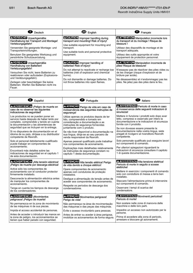
UnsachgemäßeHandhabung bei Transport und Montage!Verletzungsgefahr!Verwenden Sie geeignete Montage- undTransporteinrichtungen.Benutzen Sie geeignetes Werkzeug undpersönliche Schutzausrüstung.
Improper handling duringtransport and mounting! Risk of injury!Use suitable equipment for mounting andtransport.Use suitable tools and personal protectiveequipment.
Manipulation incorrecte lorsdu transport et du montage ! Risque deblessure !Utilisez des dispositifs de montage et detransport adéquats.Utilisez des outils appropriés et votreéquipement de protection personnel.
UnsachgemäßeHandhabung von Batterien!Verletzungsgefahr!Versuchen Sie nicht, leere Batterien zureaktivieren oder aufzuladen (Explosions-und Verätzungsgefahr).Zerlegen oder beschädigen Sie keineBatterien. Werfen Sie Batterien nicht insFeuer.
Improper handling ofbatteries! Risk of injury!Do not attempt to reactivate or recharge lowbatteries (risk of explosion and chemicalburns).Do not dismantle or damage batteries. Donot throw batteries into open flames.
Manipulation incorrecte depiles! Risque de blessure!N’essayez pas de réactiver des piles vides oude les charger (risque d’explosion et debrûlure par acide).Ne désassemblez et n’endommagez pas lespiles. Ne jetez pas des piles dans le feu.
Español Português Italiano
¡Peligro de muerte encaso de no observar las siguientesindicaciones de seguridad!Los productos no se pueden poner enservicio hasta después de haber leído porcompleto, comprendido y tenido en cuentala documentación y las advertencias deseguridad que se incluyen en la entrega.Si no dispusiera de documentación en elidioma de su país, diríjase a su distribuidorcompetente de Rexroth.Solo el personal debidamente cualificadopuede trabajar en componentes deaccionamiento.Encontrará más detalles sobre lasindicaciones de seguridad en el capítulo 1de esta documentación.
Perigo de vida em caso deinobservância das seguintes instruções desegurança!Utilize apenas os produtos depois de terlido, compreendido e tomado emconsideração a documentação e asinstruções de segurança fornecidasjuntamente com o produto.Se não tiver disponível a documentação nasua língua, dirija-se ao seu parceiro devenda responsável da Rexroth.Apenas pessoal qualificado pode trabalharnos componentes de acionamento.Explicações mais detalhadas relativamenteàs instruções de segurança constam nocapítulo 1 desta documentação.
Pericolo di morte in casodi inosservanza delle seguenti indicazioni disicurezza!Mettere in funzione i prodotti solo dopo averletto, compreso e osservato per intero ladocumentazione e le indicazioni di sicurezzafornite con il prodotto.Se non dovesse essere presente ladocumentazione nella vostra lingua, sietepregati di rivolgervi al rivenditore Rexrothcompetente.Solo personale qualificato può eseguire lavorisui componenti di comando.Per ulteriori spiegazioni riguardanti leindicazioni di sicurezza consultare il capitolo1 di questa documentazione.
¡Alta tensión eléctrica!¡Peligro de muerte por descarga eléctrica!Active sólo los componentes deaccionamiento con el conductor protectorfirmemente instalado.Desconecte la alimentación eléctrica antesde manipular los componentes deaccionamiento.Tenga en cuenta los tiempos de descargade los condensadores.
Alta tensão elétrica! Perigode vida devido a choque elétrico!Opere componentes de acionamentoapenas com condutores de proteçãoinstalados.Desligue a alimentação de tensão antes deaceder aos componentes de acionamento.Respeite os períodos de descarga doscondensadores.
Alta tensione elettrica!Pericolo di morte in seguito a scosseelettriche!Mettere in esercizio i componenti di comandosolo con conduttore di messa a terra beninstallato.Staccare l'alimentazione prima di interveniresui componenti di comando.Osservare i tempi di scarica delcondensatore.
¡Movimientospeligrosos! ¡Peligro de muerte!No permanezca en la zona de movimientode las máquinas ni de sus piezas.Impida el acceso accidental de personas.Antes de acceder o introducir las manos enla zona de peligro, los accionamientos setienen que haber parado con seguridad.
Movimentos perigosos!Perigo de vida!Não permaneça na área de movimentaçãodas máquinas e das peças das máquinas.Evite o acesso involuntário para pessoas.Antes de entrar ou aceder à área perigosa,imobilize os acionamentos de forma segura.
Movimenti pericolosi!Pericolo di morte!Non sostare nelle zone di manovra dellemacchine e delle loro parti.Impedire un accesso non autorizzato per lepersone.Prima di accedere alla zona di pericolo,arrestare e bloccare gli azionamenti.
Bosch Rexroth AG DOK-INDRV*-HMV01******-IT01-EN-P Rexroth IndraDrive Supply Units HMV01
II/81
Español Português Italiano
¡Camposelectromagnéticos/magnéticos! ¡Peligropara la salud de las personas conmarcapasos, implantes metálicos oaudífonos!El acceso de las personas arribamencionadas a las zonas de montaje ofuncionamiento de los componentes deaccionamiento está prohibido, salvo que loautorice previamente un médico.
Campos eletromagnéticos /magnéticos! Perigo de saúde para pessoascom marcapassos, implantes metálicos ouaparelhos auditivos!Acesso às áreas, nas quais oscomponentes de acionamento sãomontados e operados, é proibido para aspessoas em cima mencionadas ou apenasapós permissão de um médico.
Campi elettromagnetici /magnetici! Pericolo per la salute dellepersone portatrici di pacemaker, protesimetalliche o apparecchi acustici!L'accesso alle zone in cui sono installati o infunzione componenti di comando è vietatoper le persone sopra citate o consentito solodopo un colloquio con il medico.
¡Superficies calientes(> 60 °C)! ¡Peligro de quemaduras!Evite el contacto con las superficiescalientes (p. ej., disipadores de calor).Observe el tiempo de enfriamiento de loscomponentes de accionamiento (mín. 15minutos).
Superfícies quentes (> 60 °C)!Perigo de queimaduras!Evite tocar superfícies metálicas (p. ex.radiadores). Respeite o tempo dearrefecimento dos componentes deacionamento (mín. 15 minutos).
Superfici bollenti (> 60 °C)!Pericolo di ustioni!Evitare il contatto con superfici metalliche (ades. dissipatori di calore). Rispettare i tempi diraffreddamento dei componenti di comando(almeno 15 minuti).
¡Manipulación inadecuadaen el transporte y montaje! ¡Peligro delesiones!Utilice dispositivos de montaje y detransporte adecuados.Utilice herramientas adecuadas y equipo deprotección personal.
Manejo incorreto notransporte e montagem! Perigo deferimentos!Utilize dispositivos de montagem e detransporte adequados.Utilize ferramentas e equipamento deproteção individual adequados.
Manipolazioneinappropriata durante il trasporto e ilmontaggio! Pericolo di lesioni!Utilizzare dispositivi di montaggio e trasportoadatti.Utilizzare attrezzi adatti ed equipaggiamentodi protezione personale.
¡Manejo inadecuado de laspilas! ¡Peligro de lesiones!No trate de reactivar o cargar pilasdescargadas (peligro de explosión ycauterización).No desarme ni dañe las pilas. No tire laspilas al fuego.
Manejo incorreto de baterias!Perigo de ferimentos!Não tente reativar nem carregar bateriasvazias (perigo de explosão e dequeimaduras com ácido).Não desmonte nem danifique as baterias.Não deite as baterias no fogo.
Utilizzo inappropriato dellebatterie! Pericolo di lesioni!Non tentare di riattivare o ricaricare batteriescariche (pericolo di esplosione ecorrosione).Non scomporre o danneggiare le batterie.Non gettare le batterie nel fuoco.
Svenska Dansk Nederlands
Livsfara om följandesäkerhetsanvisningar inte följs!Använd inte produkterna innan du har lästoch förstått den dokumentation och desäkerhetsanvisningar som medföljerprodukten, och följ alla anvisningar.Kontakta din Rexroth-återförsäljare omdokumentationen inte medföljer på dittspråk.Endast kvalificerad personal får arbeta meddrivkomponenterna.Se kapitel 1 i denna dokumentation förnärmare beskrivningar avsäkerhetsanvisningarna.
Livsfare ved manglendeoverholdelse af nedenståendesikkerhedsanvisninger!Tag ikke produktet i brug, før du har læst ogforstået den dokumentation og desikkerhedsanvisninger, som følger medproduktet, og overhold de givne anvisninger.Kontakt din Rexroth-forhandler, hvisdokumentationen ikke medfølger på ditsprog.Det er kun kvalificeret personale, der måarbejde på drive components.Nærmere forklaringer tilsikkerhedsanvisningerne fremgår af kapitel1 i denne dokumentation.
Levensgevaar bij niet-naleving van onderstaandeveiligheidsinstructies!Stel de producten pas in bedrijf nadat u demet het product geleverde documenten en deveiligheidsinformatie volledig gelezen,begrepen en in acht genomen heeft.Mocht u niet beschikken over documenten inuw landstaal, kunt u contact opnemen met uwplaatselijke Rexroth distributiepartner.Uitsluitend gekwalificeerd personeel mag aande aandrijvingscomponenten werken.Meer informatie over de veiligheidsinstructiesvindt u in hoofdstuk 1 van dezedocumentatie.
Hög elektrisk spänning!Livsfara genom elchock!Använd endast drivkomponenterna medfastmonterad skyddsledare.Koppla bort spänningsförsörjningen förearbete på drivkomponenter.Var medveten om kondensatorernasurladdningstid.
Elektrisk højspænding!Livsfare på grund af elektrisk stød!Drive components må kun benyttes med etfast installeret jordstik.Sørg for at koble spændingsforsyningen fra,inden du rører ved drive components.Overhold kondensatorernes afladningstider.
Hoge elektrischespanning! Levensgevaar door elektrischeschok!Bedien de aandrijvingscomponentenuitsluitend met vast geïnstalleerdeaardleiding.Schakel voor toegang totaandrijvingscomponenten despanningsvoorziening uit.Neem de ontlaadtijden van condensatoren inacht.
DOK-INDRV*-HMV01******-IT01-EN-P Rexroth IndraDrive Supply Units HMV01
Bosch Rexroth AG III/81
Svenska Dansk Nederlands
Farliga rörelser! Livsfara!Uppehåll dig inte inom maskiners ochmaskindelars rörelseområde.Förhindra att obehöriga personer fårtillträde.Innan du börjar arbeta eller vistas inomdrivsystemets riskområde måste maskinenvara stillastående.
Farlige bevægelser!Livsfare!Du må ikke opholde dig inden for maskinersog maskindeles bevægelsesradius.Sørg for, at ingen personer kan få utilsigtetadgang.Stands drevene helt, inden du rører veddrevene eller træder ind i deres fareområde.
Risicovollebewegingen! Levensgevaar!Houdt u niet op in het bewegingsbereik vanmachines en machineonderdelen.Voorkom dat personen onbedoeld toegangverkrijgen.Voor toegang tot de gevaarlijke zone moetende aandrijvingen veilig tot stilstand gebrachtzijn.
Elektromagnetiska/magnetiskafält! Hälsofara för personer med pacemaker,implantat av metall eller hörapparat!Det är förbjudet för ovan nämnda personer(eller kräver överläggning med läkare) attbeträda områden där drivkomponenter ärmonterade och i drift.
Elektromagnetiske/magnetiske felter! Sundhedsfare forpersoner med pacemakere, metalliskeimplantater eller høreapparater!For disse personer er der adgang forbudteller kun adgang med tilladelse fra læge tilde områder, hvor drive componentsmonteres og drives.
Elektromagnetische /magnetische velden! Gevaar voor degezondheid van personen met pacemakers,metalen implantaten of hoorapparaten!Toegang tot gebieden, waarinaandrijvingscomponenten wordengemonteerd en bediend, is verboden voorvoornoemde personen of uitsluitendtoegestaan na overleg met een arts.
Varma ytor (> 60 °C)! Riskför brännskador!Undvik att vidröra metallytor (t.ex.kylelement). Var medveten om att det tar tidför drivkomponenterna att svalna (minst 15minuter).
Varme overflader (> 60 °C)!Risiko for forbrændinger!Undgå at berøre metaloverflader (f.eks.køleelementer). Overhold drive componentsnedkølingstid (min. 15 min.).
Hete oppervlakken(> 60 °C)! Verbrandingsgevaar!Voorkom contact met metalen oppervlakken(bijv. Koellichamen). Afkoeltijd van deaandrijvingscomponenten in acht nemen(min. 15 minuten).
Felaktig hantering vidtransport och montering! Skaderisk!Använd passande monterings- ochtransportanordningar.Använd lämpliga verktyg och personligskyddsutrustning.
Fejlhåndtering ved transportog montering! Risiko for kvæstelser!Benyt egnede monterings- ogtransportanordninger.Benyt egnet værktøj og personligtsikkerhedsudstyr.
Onjuist gebruik bijtransport en montage! Letselgevaar!Gebruik geschikte montage- entransportinrichtingen.Gebruik geschikt gereedschap en eenpersoonlijke veiligheidsuitrusting.
Felaktig hantering avbatterier! Skaderisk!Försök inte återaktivera eller ladda uppbatterier (risk för explosioner ochfrätskador).Batterierna får inte tas isär eller skadas.Släng inte batterierna i elden.
Fejlhåndtering af batterier!Risiko for kvæstelser!Forsøg ikke at genaktivere eller opladetomme batterier (eksplosions- ogætsningsfare).Undlad at skille batterier ad eller atbeskadige dem. Smid ikke batterier ind iåben ild.
Onjuist gebruik vanbatterijen! Letselgevaar!Probeer nooit lege batterijen te reactiveren ofop te laden (explosiegevaar en gevaar voorbeschadiging van weefsel door cauterisatie).Batterijen niet demonteren of beschadigen.Nooit batterijen in het vuur werpen.
Bosch Rexroth AG DOK-INDRV*-HMV01******-IT01-EN-P Rexroth IndraDrive Supply Units HMV01
IV/81
Suomi Polski Český
Näiden turvaohjeidennoudattamatta jättämisestä on seurauksenahengenvaara!Ota tuote käyttöön vasta sen jälkeen, kunolet lukenut läpi tuotteen mukana toimitetutasiakirjat ja turvallisuusohjeet, ymmärtänytne ja ottanut ne huomioon.Jos asiakirjoja ei ole saatavana omallaäidinkielelläsi, ota yhteys asianomaiseenRexrothin myyntiedustajaan.Käyttölaitteiden komponenttien parissa saatyöskennellä ainoastaan valtuutettuhenkilöstö.Lisätietoa turvaohjeista löydät tämändokumentaation luvusta 1.
Zagrożenie życia w razienieprzestrzegania poniższych wskazówekbezpieczeństwa!Nie uruchamiać produktów przed uprzednimprzeczytaniem i pełnym zrozumieniemwszystkich dokumentów dostarczonychwraz z produktem oraz wskazówekbezpieczeństwa. Należy przestrzegaćwszystkich zawartych tam zaleceń.W przypadku braku dokumentów w Państwajęzyku, prosimy o skontaktowanie się zlokalnym partnerem handlowym Rexroth.Przy zespołach napędowych możepracować wyłącznie wykwalifikowanypersonel.Bliższe objaśnienia wskazówekbezpieczeństwa znajdują się w Rozdziale 1niniejszej dokumentacji.
Nebezpečí života v případěnedodržení níže uvedených bezpečnostníchpokynů!Před uvedením výrobků do provozu sipřečtěte kompletní dokumentaci abezpečnostní pokyny dodávané s výrobkem,pochopte je a dodržujte.Nemáte-li k dispozici podklady ve svémjazyce, obraťte se na příslušného obchodníhopartnera Rexroth.Na komponentách pohonu smí pracovatpouze kvalifikovaný personál.Podrobnější vysvětlení k bezpečnostnímpokynům naleznete v kapitole 1 tétodokumentace.
Voimakas sähköjännite!Sähköiskun aiheuttama hengenvaara!Käytä käyttölaitteen komponenttejaainoastaan maadoitusjohtimen ollessakiinteästi asennettuna.Katkaise jännitteensyöttö ennenkäyttölaitteen komponenteille suoritettavientöiden aloittamista.Huomioi kondensaattoreiden purkausajat.
Wysokie napięcieelektryczne! Zagrożenie życia w wynikuporażenia prądem!Zespoły napędu mogą być eksploatowanewyłącznie z zainstalowanym na stałeprzewodem ochronnym.Przed uzyskaniem dostępu do podzespołównapędu należy odłączyć zasilanieelektryczne.Zwracać uwagę na czas rozładowaniakondensatorów.
Vysoké elektrické napětí!Nebezpečí života při zasažení elektrickýmproudem!Komponenty pohonu smí být v provozupouze s pevně nainstalovaným ochrannýmvodičem.Než začnete zasahovat do komponentpohonu, odpojte je od elektrického napájení.Dodržujte vybíjecí časy kondenzátorů.
Vaarallisia liikkeitä!Hengenvaara!Älä oleskele koneiden tai koneenosienliikealueella.Pidä huolta siitä, ettei muita henkilöitäpääse alueelle vahingossa.Pysäytä käyttölaitteet varmasti ennen vaara-alueelle koskemista tai menemistä.
Niebezpieczne ruchy!Zagrożenie życia!Nie wolno przebywać w obszarze pracymaszyny i jej elementów.Nie dopuszczać osób niepowołanych doobszaru pracy maszyny.Przed dotknięciem urządzenia/maszyny lubzbliżeniem się do obszaru zagrożenianależy zgodnie z zasadami bezpieczeństwawyłączyć napędy.
Nebezpečné pohyby!Nebezpečí života!Nezdržujte se v dosahu pohybu strojů a jejichsoučástí.Zabraňte náhodnému přístupu osob.Před zásahem nebo vstupem donebezpečného prostoru bezpečně zastavtepohony.
Sähkömagneettisia/magneettisia kenttiä! Terveydellistenhaittojen vaara henkilöille, joilla onsydämentahdistin, metallinen implantti taikuulolaite!Yllä mainituilta henkilöiltä on pääsy kiellettyalueille, joilla asennetaan tai käytetäänkäyttölaitteen komponentteja, tai heidän onensin saatava tähän suostumuslääkäriltään.
Polaelektromagnetyczne / magnetyczne!Zagrożenie zdrowia dla osób zrozrusznikiem serca, metalowymiimplantami lub aparatami słuchowymi!Wstęp na teren, gdzie odbywa się montaż ieksploatacja napędów jest dla ww. osóbzabroniony względnie dozwolony pokonsultacji z lekarzem.
Elektromagnetická/magnetická pole! Nebezpečí pro zdraví osobs kardiostimulátory, kovovými implantátynebo naslouchadly!Výše uvedené osoby mají zakázán přístup doprostorů, kde jsou montovány a používánykomponenty pohonu, resp. ho mají povolenpouze po poradě s lékařem.
Kuumia pintoja (> 60 °C)!Palovammojen vaara!Vältä metallipintojen koskettamista (esim.jäähdytyslevyt). Noudata käyttölaitteenkomponenttien jäähtymisaikoja (väh. 15minuuttia).
Gorące powierzchnie(> 60 °C)! Niebezpieczeństwo poparzenia!Unikać kontaktu z powierzchniamimetalowymi (np. radiatorami). Przestrzegaćczasów schładzania podzespołów napędów(min. 15 minut).
Horké povrchy (> 60 °C)!Nebezpečí popálení!Nedotýkejte se kovových povrchů (např.chladicích těles). Dodržujte dobu ochlazeníkomponent pohonu (min. 15 minut).
DOK-INDRV*-HMV01******-IT01-EN-P Rexroth IndraDrive Supply Units HMV01
Bosch Rexroth AG V/81
Suomi Polski Český
Epäasianmukainen käsittelykuljetuksen ja asennuksen yhteydessä!Loukkaantumisvaara!Käytä soveltuvia asennus- jakuljetuslaitteita.Käytä omia työkaluja ja henkilökohtaisiasuojavarusteita.
Niewłaściweobchodzenie się podczas transportu imontażu! Ryzyko urazu!Stosować odpowiednie urządzeniamontażowe i transportowe.Stosować odpowiednie narzędzia i środkiochrony osobistej.
Nesprávné zacházení připřepravě a montáži! Nebezpečí zranění!Používejte vhodná montážní a dopravnízařízení.Používejte vhodné nářadí a osobní ochrannévybavení.
Paristojen epäasianmukainenkäsittely! Loukkaantumisvaara!Älä yritä saada tyhjiä paristoja toimimaan tailadata niitä uudelleen (räjähdys- jasyöpymisvaara).Älä hajota paristoja osiin tai vaurioita niitä.Älä heitä paristoja tuleen.
Niewłaściweobchodzenie się z bateriami! Ryzyko urazu!Nie próbować reaktywować i nie ładowaćzużytych baterii (niebezpieczeństwowybuchu oraz poparzenia żrącąsubstancją).Nie demontować i nie niszczyć baterii. Niewrzucać baterii do ognia.
Nesprávné zacházení sbateriemi! Nebezpečí zranění!Nepokoušejte se znovu aktivovat nebodobíjet prázdné baterie (nebezpečí výbuchu apoleptání).Nerozebírejte ani nepoškozujte baterie.Neházejte baterie do ohně.
Slovensko Slovenčina Română
Življenjska nevarnost prineupoštevanju naslednjih napotkov zavarnost!Izdelke začnite uporabljati šele, ko v celotipreberete, razumete in upoštevate izdelkompriloženo dokumentacijo in varnostnenapotke.Če priložena dokumentacija ni na voljo vvašem maternem jeziku, se obrnite napristojnega distributerja Rexroth.Samo kvalificirano osebje sme delati napogonskih komponentah.Podrobnejša pojasnila o varnostnihnavodilih najdete v poglavju 1 v tejdokumentaciji.
Nebezpečenstvo ohrozeniaživota pri nedodržiavaní nasledujúcichbezpečnostných pokynov!Výrobky uvádzajte do prevádzky až potom,čo ste úplne prečítali, pochopili a zobrali doúvahy podklady a bezpečnostné pokynydodané s výrobkom.Ak by ste nemali k dispozícii žiadnepodklady v jazyku svojej krajiny, obráťte saprosím na svojho príslušného predajcuRexroth.Na komponentoch pohonu smie pracovaťiba kvalifikovaný personál.Bližšie vysvetlenia k bezpečnostnýmpokynom zistite z kapitoly 1 tejtodokumentácie.
Pericol de moarte în cazulnerespectării următoarelor instrucţiuni desiguranţă!Punerea în funcţiune a produselor trebuieefectuată după citirea, înţelegerea şirespectarea documentelor şi instrucţiunilor desiguranţă, care sunt livrate împreună cuprodusele.În cazul în care documentele nu sunt în limbadumneavoastră maternă, vă rugăm săcontactaţi partenerul de vânzări Rexroth.Numai un personal calificat poate lucra cucomponentele de acţionare.Explicaţii detaliate privind instrucţiunile desiguranţă găsiţi în capitolul 1 al acesteidocumentaţii.
Visoka električna napetost!Življenjska nevarnost zaradi električnegaudara!Pogonske komponente uporabljajte samo sfiksno nameščenim zaščitnim vodnikom.Pred dostopom do pogonske komponenteodklopite napajanje.Upoštevajte čase praznjenjakondenzatorjev.
Vysoké elektrické napätie!Nebezpečenstvo ohrozenia života vdôsledku zásahu elektrickým prúdom!Komponenty pohonu prevádzkujte iba spevne nainštalovaným ochranným vodičom.Pred prístupom na komponenty pohonuodpojte zdroj napätia.Rešpektujte časy vybitia kondenzátorov.
Tensiune electrică înaltă!Pericol de moarte prin electrocutare!Exploataţi componentele de acţionare numaicu împământarea instalată permanent.Înainte de intervenţia asupra componentelorde acţionare, deconectaţi alimentarea cutensiune electrică.Ţineţi cont de timpii de descărcare aicondensatorilor.
Nevarni premiki!Življenjska nevarnost!Ne zadržujte se v območju delovanjastrojev.Preprečite nenadzorovan dostop oseb.Pred prijemom ali dostopom v nevarnoobmočje varno zaustavite vse gnane dele.
Pohyby prinášajúcenebezpečenstvo! Nebezpečenstvoohrozenia života!Nezdržiavajte sa v oblasti pohybu strojov ačastí strojov.Zabráňte nepovolanému prístupu osôb.Pred zásahom alebo prístupom donebezpečnej oblasti uveďte pohonybezpečne do zastavenia.
Mişcări periculoase! Pericolde moarte!Nu staţionaţi în zona de mişcare a maşinilorşi a componentelor în mişcare a maşinilor.Împiedicaţi accesul neintenţionat alpersoanelor în zona de lucru a maşinilor.Înainte de intervenţia sau accesul în zonapericuloasă, opriţi în siguranţă componentelede acţionare.
Bosch Rexroth AG DOK-INDRV*-HMV01******-IT01-EN-P Rexroth IndraDrive Supply Units HMV01
VI/81
Slovensko Slovenčina Română
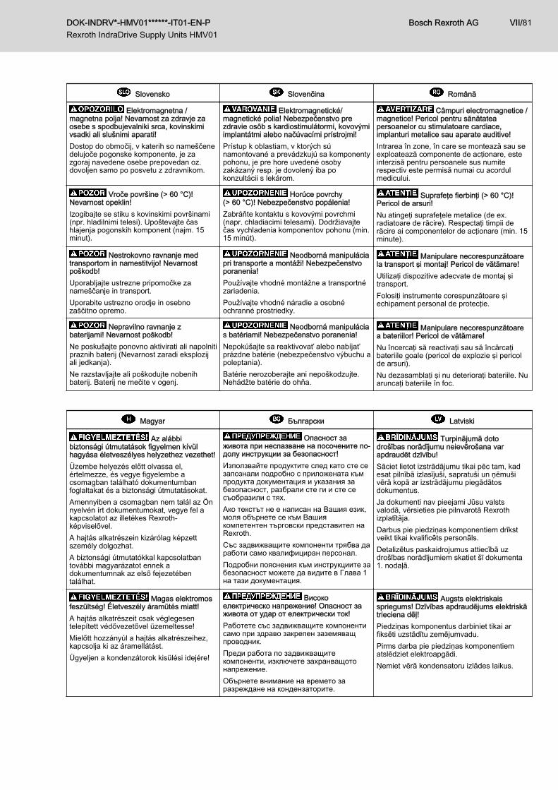
Elektromagnetna /magnetna polja! Nevarnost za zdravje zaosebe s spodbujevalniki srca, kovinskimivsadki ali slušnimi aparati!Dostop do območij, v katerih so nameščenedelujoče pogonske komponente, je zazgoraj navedene osebe prepovedan oz.dovoljen samo po posvetu z zdravnikom.
Elektromagnetické/magnetické polia! Nebezpečenstvo prezdravie osôb s kardiostimulátormi, kovovýmiimplantátmi alebo načúvacími prístrojmi!Prístup k oblastiam, v ktorých súnamontované a prevádzkujú sa komponentypohonu, je pre hore uvedené osobyzakázaný resp. je dovolený iba pokonzultácii s lekárom.
Câmpuri electromagnetice /magnetice! Pericol pentru sănătateapersoanelor cu stimulatoare cardiace,implanturi metalice sau aparate auditive!Intrarea în zone, în care se montează sau seexploatează componente de acţionare, esteinterzisă pentru persoanele sus numiterespectiv este permisă numai cu acordulmedicului.
Vroče površine (> 60 °C)!Nevarnost opeklin!Izogibajte se stiku s kovinskimi površinami(npr. hladilnimi telesi). Upoštevajte čashlajenja pogonskih komponent (najm. 15minut).
Horúce povrchy(> 60 °C)! Nebezpečenstvo popálenia!Zabráňte kontaktu s kovovými povrchmi(napr. chladiacimi telesami). Dodržiavajtečas vychladenia komponentov pohonu (min.15 minút).
Suprafeţe fierbinţi (> 60 °C)!Pericol de arsuri!Nu atingeţi suprafeţele metalice (de ex.radiatoare de răcire). Respectaţi timpii derăcire ai componentelor de acţionare (min. 15minute).
Nestrokovno ravnanje medtransportom in namestitvijo! Nevarnostpoškodb!Uporabljajte ustrezne pripomočke zanameščanje in transport.Uporabite ustrezno orodje in osebnozaščitno opremo.
Neodborná manipuláciapri transporte a montáži! Nebezpečenstvoporanenia!Používajte vhodné montážne a transportnézariadenia.Používajte vhodné náradie a osobnéochranné prostriedky.
Manipulare necorespunzătoarela transport şi montaj! Pericol de vătămare!Utilizaţi dispozitive adecvate de montaj şitransport.Folosiţi instrumente corespunzătoare şiechipament personal de protecţie.
Nepravilno ravnanje zbaterijami! Nevarnost poškodb!Ne poskušajte ponovno aktivirati ali napolnitipraznih baterij (Nevarnost zaradi eksplozijali jedkanja).Ne razstavljajte ali poškodujte nobenihbaterij. Baterij ne mečite v ogenj.
Neodborná manipulácias batériami! Nebezpečenstvo poranenia!Nepokúšajte sa reaktivovať alebo nabíjaťprázdne batérie (nebezpečenstvo výbuchu apoleptania).Batérie nerozoberajte ani nepoškodzujte.Nehádžte batérie do ohňa.
Manipulare necorespunzătoarea bateriilor! Pericol de vătămare!Nu încercaţi să reactivaţi sau să încărcaţibateriile goale (pericol de explozie şi pericolde arsuri).Nu dezasamblaţi şi nu deterioraţi bateriile. Nuaruncaţi bateriile în foc.
Magyar Български Latviski
Az alábbibiztonsági útmutatások figyelmen kívülhagyása életveszélyes helyzethez vezethet!Üzembe helyezés előtt olvassa el,értelmezze, és vegye figyelembe acsomagban található dokumentumbanfoglaltakat és a biztonsági útmutatásokat.Amennyiben a csomagban nem talál az Önnyelvén írt dokumentumokat, vegye fel akapcsolatot az illetékes Rexroth-képviselővel.A hajtás alkatrészein kizárólag képzettszemély dolgozhat.A biztonsági útmutatókkal kapcsolatbantovábbi magyarázatot ennek adokumentumnak az első fejezetébentalálhat.
Опасност заживота при неспазване на посочените по-долу инструкции за безопасност!Използвайте продуктите след като сте сезапознали подробно с приложената къмпродукта документация и указания забезопасност, разбрали сте ги и сте сесъобразили с тях.Ако текстът не е написан на Вашия език,моля обърнете се към Вашиякомпетентен търговски представител наRexroth.Със задвижващите компоненти трябва даработи само квалифициран персонал.Подробни пояснения към инструкциите забезопасност можете да видите в Глава 1на тази документация.
Turpinājumā dotodrošības norādījumu neievērošana varapdraudēt dzīvību!Sāciet lietot izstrādājumu tikai pēc tam, kadesat pilnībā izlasījuši, sapratuši un ņēmušivērā kopā ar izstrādājumu piegādātosdokumentus.Ja dokumenti nav pieejami Jūsu valstsvalodā, vērsieties pie pilnvarotā Rexrothizplatītāja.Darbus pie piedziņas komponentiem drīkstveikt tikai kvalificēts personāls.Detalizētus paskaidrojumus attiecībā uzdrošības norādījumiem skatiet šī dokumenta1. nodaļā.
Magas elektromosfeszültség! Életveszély áramütés miatt!A hajtás alkatrészeit csak véglegesentelepített védővezetővel üzemeltesse!Mielőtt hozzányúl a hajtás alkatrészeihez,kapcsolja ki az áramellátást.Ügyeljen a kondenzátorok kisülési idejére!
Високоелектрическо напрежение! Опасност заживота от удар от електрически ток!Работете със задвижващите компонентисамо при здраво закрепен заземяващпроводник.Преди работа по задвижващитекомпоненти, изключете захранващотонапрежение.Обърнете внимание на времето заразреждане на кондензаторите.
Augsts elektriskaisspriegums! Dzīvības apdraudējums elektriskātrieciena dēļ!Piedziņas komponentus darbiniet tikai arfiksēti uzstādītu zemējumvadu.Pirms darba pie piedziņas komponentiematslēdziet elektroapgādi.Ņemiet vērā kondensatoru izlādes laikus.
DOK-INDRV*-HMV01******-IT01-EN-P Rexroth IndraDrive Supply Units HMV01
Bosch Rexroth AG VII/81
Magyar Български Latviski
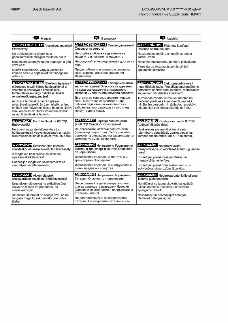
Veszélyes mozgás!Életveszély!Ne tartózkodjon a gépek és agépalkatrészek mozgási területén belül!Illetéktelen személyeket ne engedjen a gépközelébe!Mielőtt beavatkozik, vagy a veszélyeszónába belép a hajtásokat biztonságosanállítsa le.
Опасни движения!Опасност за живота!Не стойте в обсега на движение намашините и частите на машините.Не допускайте непреднамерен достъп нахора.Преди работа или влизане в опаснатазона, спрете надеждно приводниямеханизъм.
Bīstamas kustības!Dzīvības apdraudējums!Neuzturieties mašīnu un mašīnas detaļukustību zonā.Novērsiet nepiederošu personu piekļūšanu.Pirms darba bīstamajās zonās pilnībāapstādiniet piedziņu.
Elektromágneses /mágneses mező! Káros hatással lehet aszívritmus-szabályozó készülékkel,fémbeültetéssel vagy hallókészülékkelrendelkezők egészségére!Azokra a területekre, ahol hajtásokalkatrészeit szerelik és üzemeltetik, a fentemlített személyeknek tilos a belépés, illetvecsak orvosi konzultációt követően szabadaz adott területekre lépniük.
Електромагнитни /магнитни полета! Опасност за здраветона хора със сърдечни стимулатори,метални импланти или слухови апарати!Достъпът за гореспоменатите лица дозони, в които ще се монтират и щеработят задвижващи компоненти сезабранява, или разрешава само следконсултация с лекар.
Elektromagnētiskais /magnētiskais lauks! Veselības apdraudējumspersonām ar sirds stimulatoriem, metāliskiemimplantiem vai dzirdes aparātiem!Tuvošanās zonām, kurās tiek montēti undarbināti piedziņas komponenti, iepriekšminētajām personām ir aizliegta, respektīvi,atļauta tikai pēc konsultēšanās ar ārstu.
Forró felületek (> 60 °C)!Égésveszély!Ne érjen hozzá fémfelületekhez (pl.hűtőtestekhez)! Vegye figyelembe a hajtásalkatrészeinek kihűlési idejét (min. 15 perc)!
Горещи повърхности(> 60 °C)! Опасност от изгаряне!Не докосвайте метални повърхности(например радиатори). Съблюдавайтевремето на охлаждане на задвижващитекомпоненти (мин. 15 минути).
Karstas virsmas (> 60 °C)!Apdedzināšanās risks!Neskarieties pie metāliskām virsmām(piemēram, dzesētāja). Ļaujiet piedziņaskomponentiem atdzist (min. 15 minūtes).
Szakszerűtlen kezelésszállításkor és szereléskor! Sérülésveszély!A megfelelő beszerelési és szállításieljárásokat alkalmazza!Használjon megfelelő szerszámokat ésszemélyes védőfelszerelést!
Неправилно боравене повреме на транспорт и монтаж!Опасностот нараняване!Използвайте подходящо монтажно итранспортно оборудване.Използвайте подходящи инструменти илични предпазни средства.
Nepareizi veiktatransportēšana un montāža! Traumu gūšanasrisks!Izmantojiet piemērotas montāžas untransportēšanas ierīces.Izmantojiet piemērotus instrumentus unindividuālos aizsardzības līdzekļus.
Akkumulátorokszakszerűtlen kezelése! Sérülésveszély!Üres akkumulátorokat ne aktiváljon újra,illetve ne töltsön fel (robbanás- ésmarásveszély)!Az akkumulátorokat ne szedje szét, és nerongálja meg! Az akkumulátort ne dobjatűzbe!
Неправилно боравене сбатерии! Опасност от нараняване!Не се опитвайте да активирате отновоили да зареждате разредени батерии(Опасност от експлозия и напръскване сагресивен агент).Не разглобявайте и не повреждайтебатерии. Не хвърляйте батерии в огън.
Nepareiza bateriju lietošana!Traumu gūšanas risks!Nemēģiniet no jauna aktivizēt vai uzlādēttukšas baterijas (eksploziju un ķīmiskoapdegumu draudi).Neizjauciet un nesabojājiet baterijas.Nemetiet baterijas ugunī.
Bosch Rexroth AG DOK-INDRV*-HMV01******-IT01-EN-P Rexroth IndraDrive Supply Units HMV01
VIII/81
Lietuviškai Eesti Ελληνικά
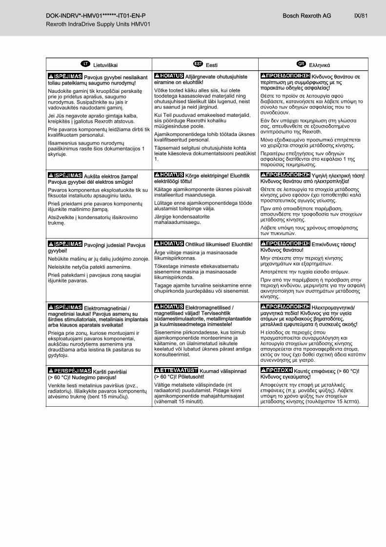
Pavojus gyvybei nesilaikanttoliau pateikiamų saugumo nurodymų!Naudokite gaminį tik kruopščiai perskaitęprie jo pridėtus aprašus, saugumonurodymus. Susipažinkite su jais irvadovaukitės naudodami gaminį.Jei Jūs negavote aprašo gimtąja kalba,kreipkitės į įgaliotus Rexroth atstovus.Prie pavaros komponentų leidžiama dirbti tikkvalifikuotam personalui.Išsamesnius saugumo nurodymųpaaiškinimus rasite šios dokumentacijos 1skyriuje.
Alljärgnevate ohutusjuhisteeiramine on eluohtlik!Võtke tooted käiku alles siis, kui oletetoodetega kaasasolevad materjalid ningohutusjuhised täielikult läbi lugenud, neistaru saanud ja neid järginud.Kui Teil puuduvad emakeelsed materjalid,siis pöörduge Rexrothi kohalikumüügiesinduse poole.Ajamikomponentidega tohib töötada üksneskvalifitseeritud personal.Täpsemaid selgitusi ohutusjuhiste kohtaleiate käesoleva dokumentatsiooni peatükist1.
Κίνδυνος θανάτου σεπερίπτωση μη συμμόρφωσης με τιςπαρακάτω οδηγίες ασφαλείας!Θέστε το προϊόν σε λειτουργία αφούδιαβάσετε, κατανοήσετε και λάβετε υπόψη τοσύνολο των οδηγιών ασφαλείας που τοσυνοδεύουν.Εάν δεν υπάρχει τεκμηρίωση στη γλώσσασας, απευθυνθείτε σε εξουσιοδοτημένοαντιπρόσωπο της Rexroth.Μόνο εξειδικευμένο προσωπικό επιτρέπεταινα χειρίζεται στοιχεία μετάδοσης κίνησης.Περαιτέρω επεξηγήσεις των οδηγιώνασφαλείας διατίθενται στο κεφάλαιο 1 τηςπαρούσας τεκμηρίωσης.
Aukšta elektros įtampa!Pavojus gyvybei dėl elektros smūgio!Pavaros komponentus eksploatuokite tik sufiksuotai instaliuotu apsauginiu laidu.Prieš prieidami prie pavaros komponentųišjunkite maitinimo įtampą.Atsižvelkite į kondensatorių išsikrovimotrukmę.
Kõrge elektripinge! Eluohtlikelektrilöögi tõttu!Käitage ajamikomponente üksnes püsivaltinstalleeritud maandusega.Lülitage enne ajamikomponentidega töödealustamist toitepinge välja.Järgige kondensaatoritemahalaadumisaegu.
Υψηλή ηλεκτρική τάση!Κίνδυνος θανάτου από ηλεκτροπληξία!Θέτετε σε λειτουργία τα στοιχεία μετάδοσηςκίνησης μόνο εφόσον έχει τοποθετηθεί καλάπροστατευτικός αγωγός γείωσης.Πριν από οποιαδήποτε παρέμβαση,αποσυνδέστε την τροφοδοσία των στοιχείωνμετάδοσης κίνησης.Λάβετε υπόψη τους χρόνους αποφόρτισηςτων πυκνωτών.
Pavojingi judesiai! Pavojusgyvybei!Nebūkite mašinų ar jų dalių judėjimo zonoje.Neleiskite netyčia patekti asmenims.Prieš patekdami į pavojaus zoną saugiaiišjunkite pavaras.
Ohtlikud liikumised! Eluohtlik!Ärge viibige masina ja masinaosadeliikumispiirkonnas.Tõkestage inimeste ettekavatsematusisenemine masina ja masinaosadeliikumispiirkonda.Tagage ajamite turvaline seiskamine enneohupiirkonda juurdepääsu või sisenemist.
Επικίνδυνες τάσεις!Κίνδυνος θανάτου!Μην στέκεστε στην περιοχή κίνησηςμηχανημάτων και εξαρτημάτων.Αποτρέπετε την τυχαία είσοδο ατόμων.Πριν από την παρέμβαση ή πρόσβαση στηνπεριοχή κινδύνου, μεριμνήστε για την ασφαλήακινητοποίηση των συστημάτων μετάδοσηςκίνησης.
Elektromagnetiniai /magnetiniai laukai! Pavojus asmenų suširdies stimuliatoriais, metaliniais implantaisarba klausos aparatais sveikatai!Prieiga prie zonų, kuriose montuojami ireksploatuojami pavaros komponentai,aukščiau nurodytiems asmenims yradraudžiama arba leistina tik pasitarus sugydytoju.
Elektromagnetilised /magnetilised väljad! Terviseohtliksüdamestimulaatorite, metallimplantaatideja kuulmisseadmetega inimestele!Sisenemine piirkondadesse, kus toimubajamikomponentide monteerimine jakäitamine, on ülalnimetatud isikutelekeelatud või lubatud üksnes pärast arstigakonsulteerimist.
Ηλεκτρομαγνητικά/μαγνητικά πεδία! Κίνδυνος για την υγείαατόμων με καρδιακούς βηματοδότες,μεταλλικά εμφυτεύματα ή συσκευές ακοής!Η είσοδος σε περιοχές όπουπραγματοποιείται συναρμολόγηση καιλειτουργία στοιχείων μετάδοσης κίνησηςαπαγορεύεται στα προαναφερθέντα άτομα,εκτός αν τους έχει δοθεί σχετική άδεια κατόπινσυνεννόησης με γιατρό.
Karšti paviršiai(> 60 °C)! Nudegimo pavojus!Venkite liesti metalinius paviršius (pvz.,radiatorių). Išlaikykite pavaros komponentųatvėsimo trukmę (bent 15 minučių).
Kuumad välispinnad(> 60 °C)! Põletusoht!Vältige metalsete välispindade (ntradiaatorid) puudutamist. Pidage kinniajamikomponentide mahajahtumisajast(vähemalt 15 minutit).
Καυτές επιφάνειες (> 60 °C)!Κίνδυνος εγκαύματος!Αποφεύγετε την επαφή με μεταλλικέςεπιφάνειες (π.χ. μονάδες ψύξης). Λάβετευπόψη το χρόνο ψύξης των στοιχείωνμετάδοσης κίνησης (τουλάχιστον 15 λεπτά).
DOK-INDRV*-HMV01******-IT01-EN-P Rexroth IndraDrive Supply Units HMV01
Bosch Rexroth AG IX/81
Lietuviškai Eesti Ελληνικά
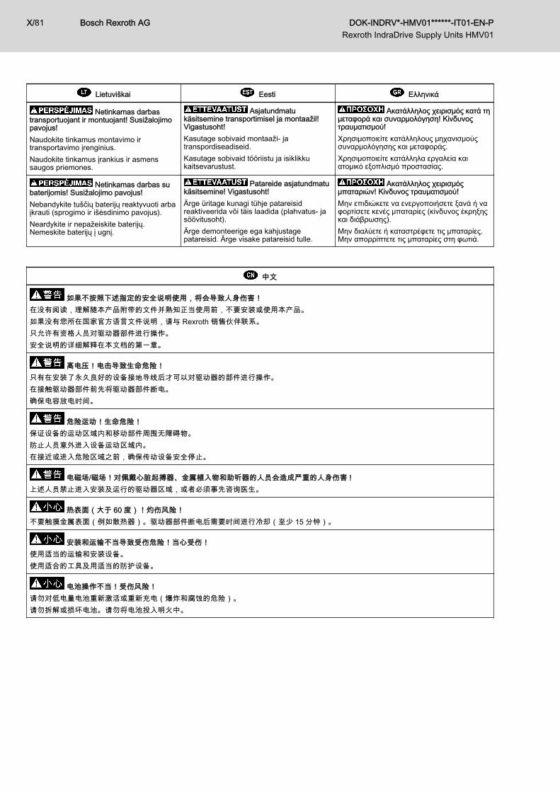
Netinkamas darbastransportuojant ir montuojant! Susižalojimopavojus!Naudokite tinkamus montavimo irtransportavimo įrenginius.Naudokite tinkamus įrankius ir asmenssaugos priemones.
Asjatundmatukäsitsemine transportimisel ja montaažil!Vigastusoht!Kasutage sobivaid montaaži- jatranspordiseadiseid.Kasutage sobivaid tööriistu ja isiklikkukaitsevarustust.
Ακατάλληλος χειρισμός κατά τημεταφορά και συναρμολόγηση! Κίνδυνοςτραυματισμού!Χρησιμοποιείτε κατάλληλους μηχανισμούςσυναρμολόγησης και μεταφοράς.Χρησιμοποιείτε κατάλληλα εργαλεία καιατομικό εξοπλισμό προστασίας.
Netinkamas darbas subaterijomis! Susižalojimo pavojus!Nebandykite tuščių baterijų reaktyvuoti arbaįkrauti (sprogimo ir išėsdinimo pavojus).Neardykite ir nepažeiskite baterijų.Nemeskite baterijų į ugnį.
Patareide asjatundmatukäsitsemine! Vigastusoht!Ärge üritage kunagi tühje patareisidreaktiveerida või täis laadida (plahvatus- jasöövitusoht).Ärge demonteerige ega kahjustagepatareisid. Ärge visake patareisid tulle.
Ακατάλληλος χειρισμόςμπαταριών! Κίνδυνος τραυματισμού!Μην επιδιώκετε να ενεργοποιήσετε ξανά ή ναφορτίσετε κενές μπαταρίες (κίνδυνος έκρηξηςκαι διάβρωσης).Μην διαλύετε ή καταστρέφετε τις μπαταρίες.Μην απορρίπτετε τις μπαταρίες στη φωτιά.
中文
如果不按照下述指定的安全说明使用,将会导致人身伤害!在没有阅读,理解随本产品附带的文件并熟知正当使用前,不要安装或使用本产品。如果没有您所在国家官方语言文件说明,请与 Rexroth 销售伙伴联系。只允许有资格人员对驱动器部件进行操作。安全说明的详细解释在本文档的第一章。
高电压!电击导致生命危险!只有在安装了永久良好的设备接地导线后才可以对驱动器的部件进行操作。在接触驱动器部件前先将驱动器部件断电。确保电容放电时间。
危险运动!生命危险!保证设备的运动区域内和移动部件周围无障碍物。防止人员意外进入设备运动区域内。在接近或进入危险区域之前,确保传动设备安全停止。
电磁场/磁场!对佩戴心脏起搏器、金属植入物和助听器的人员会造成严重的人身伤害 !上述人员禁止进入安装及运行的驱动器区域,或者必须事先咨询医生。
热表面(大于 60 度)!灼伤风险!不要触摸金属表面(例如散热器)。驱动器部件断电后需要时间进行冷却(至少 15 分钟)。
安装和运输不当导致受伤危险!当心受伤!使用适当的运输和安装设备。使用适合的工具及用适当的防护设备。
电池操作不当!受伤风险!请勿对低电量电池重新激活或重新充电(爆炸和腐蚀的危险)。请勿拆解或损坏电池。请勿将电池投入明火中。
Bosch Rexroth AG DOK-INDRV*-HMV01******-IT01-EN-P Rexroth IndraDrive Supply Units HMV01
X/81
Table of ContentsPage
1 Important Notes........................................................................................................... 131.1 Safety Instructions................................................................................................................................ 131.1.1 General Information........................................................................................................................... 131.1.2 Protection Against Contact With Electrical Parts and Housings........................................................ 141.1.3 Protection Against Dangerous Movements....................................................................................... 151.1.4 Protection Against Magnetic and Electromagnetic Fields During Operation and Mounting.............. 171.1.5 Protection Against Contact With Hot Parts........................................................................................ 171.1.6 Protection During Handling and Mounting......................................................................................... 171.1.7 Battery Safety.................................................................................................................................... 181.2 Appropriate Use.................................................................................................................................... 18
2 Identification................................................................................................................. 212.1 Type Code............................................................................................................................................ 212.2 Type Plates........................................................................................................................................... 222.3 Scope of Supply.................................................................................................................................... 22
3 Ratings and Dimensions.............................................................................................. 233.1 HMV01.1E............................................................................................................................................ 233.2 HMV01.1R............................................................................................................................................ 24
4 Documentations........................................................................................................... 274.1 Drive Systems, System Components................................................................................................... 274.2 Motors................................................................................................................................................... 274.3 Cables................................................................................................................................................... 284.4 Firmware............................................................................................................................................... 28
5 Instructions for Use...................................................................................................... 315.1 Power Supply and Input Voltage.......................................................................................................... 315.2 Connection Points................................................................................................................................. 315.2.1 Wiring Diagram.................................................................................................................................. 315.2.2 Connection Diagram.......................................................................................................................... 325.2.3 X3, Mains Connection....................................................................................................................... 35
Important Notes.............................................................................................................................. 35HMV01.1E-W0030, ‑W0075; HMV01.1R-W0018, ‑W0045, ‑W0065.............................................. 36HMV01.1E-W0120; HMV01.1R-W0120......................................................................................... 36
5.2.4 X13, Supply Fan Unit HAB01............................................................................................................ 375.2.5 X14, Mains Voltage Synchronization................................................................................................. 38
Connection Point............................................................................................................................ 38Mains Voltage Synchronization...................................................................................................... 39
5.2.6 X31, Messages Bb1, UD, WARN...................................................................................................... 405.2.7 X32, Mains Contactor Control and DC Bus Short Circuit.................................................................. 425.2.8 X33, Acknowledge Messages of Integrated Mains Contactor........................................................... 455.2.9 X34, Contact for Controlling the External Mains Contactor............................................................... 47
DOK-INDRV*-HMV01******-IT01-EN-P Rexroth IndraDrive Supply Units HMV01
Bosch Rexroth AG XI/81
Table of Contents
Page
5.2.10 X40, Acknowledge Messages of External Mains Contactor.............................................................. 495.2.11 Terminal Block, 24V - 0V (24V Supply)............................................................................................. 505.2.12 L+ L-, DC Bus Connection................................................................................................................. 525.2.13 Connection Point of Equipment Grounding Conductor, HMV............................................................ 545.2.14 Ground Connection........................................................................................................................... 565.2.15 Shield Connection............................................................................................................................. 56
XS1, Shield Connection Control Lines........................................................................................... 565.3 Installation............................................................................................................................................. 575.3.1 General Information on How to Install the Drive Controller............................................................... 575.3.2 Sizing of Enclosure and Control Cabinet........................................................................................... 58
Multiple-Line Design of the Control Cabinet................................................................................... 58Arranging the Cooling Units............................................................................................................ 59
6 EMC Measures for Design and Installation.................................................................. 616.1 Rules for Design of Installations With Drive Controllers in Compliance With EMC.............................. 616.2 EMC-Optimal Installation in Facility and Control Cabinet..................................................................... 626.2.1 General Information........................................................................................................................... 626.2.2 Division Into Areas (Zones)............................................................................................................... 626.2.3 Control Cabinet Design According to Interference Areas - Exemplary Arrangements...................... 636.2.4 Design and Installation in Area A - Interference-Free Area of Control Cabinet................................. 676.2.5 Design and Installation in Area B - Interference-Susceptible Area of Control Cabinet...................... 696.2.6 Design and Installation in Area C - Strongly Interference-Susceptible Area of Control Cabinet....... 696.3 Ground Connections............................................................................................................................. 706.4 Installing Signal Lines and Signal Cables............................................................................................. 716.5 General Measures of Radio Interference Suppression for Relays, Contactors, Switches, Chokes and
Inductive Loads..................................................................................................................................... 72
7 Accessories.................................................................................................................. 737.1 Overview............................................................................................................................................... 73
8 Service and Support.................................................................................................... 75
9 Environmental Protection and Disposal ...................................................................... 779.1 Environmental Protection...................................................................................................................... 779.2 Disposal................................................................................................................................................ 77
Index............................................................................................................................ 79
Bosch Rexroth AG DOK-INDRV*-HMV01******-IT01-EN-P Rexroth IndraDrive Supply Units HMV01
XII/81
Table of Contents
1 Important Notes1.1 Safety Instructions1.1.1 General Information
● Do not attempt to install and operate the components of the electricdrive and control system without first reading all documentation providedwith the product. Read and understand these safety instructions and alluser documentation prior to working with these components. If you donot have the user documentation for the components, contact your re‐sponsible Rexroth sales partner. Ask for these documents to be sent im‐mediately to the person or persons responsible for the safe operation ofthe components.
● If the supplied documents contain some information you do not under‐stand, it is absolutely necessary that you ask Rexroth for explanationbefore you start working at or with the components.
● If the component is resold, rented and/or passed on to others in any oth‐er form, these safety instructions must be delivered with the componentin the official language of the user's country.
● Only qualified persons may work with components of the electric driveand control system or within its proximity.In terms of this Instruction Manual, qualified persons are those personswho are familiar with the installation, mounting, commissioning and op‐eration of the components of the electric drive and control system, aswell as with the hazards this implies, and who possess the qualificationstheir work requires. To comply with these qualifications, it is necessary,among other things,– to be trained, instructed or authorized to switch electric circuits and
components safely on and off, to ground them and to mark them,– to be trained or instructed to maintain and use adequate safety
equipment,– to attend a course of instruction in first aid.
● The technical data, connection and installation conditions of the compo‐nents are specified in the respective application documentations andmust be followed at all times.
● If the components take the form of hardware, then they must remain intheir original state, in other words, no structural changes are permitted.It is not permitted to decompile software components or alter source co‐des.
● Do not mount damaged or faulty components or use them in operation.● Only use accessories and spare parts approved by Rexroth.● Follow the safety regulations and requirements of the country in which
the electric components of the electric drive and control system are op‐erated.
● Proper and correct transport, storage, mounting and installation, as wellas care in operation and maintenance, are prerequisites for optimal andsafe operation of the component.
Improper use of these components, failure to follow the safety instructions inthis document or tampering with the product, including disabling of safety de‐vices, could result in property damage, injury, electric shock or even death.
DOK-INDRV*-HMV01******-IT01-EN-P Rexroth IndraDrive Supply Units HMV01
Bosch Rexroth AG 13/81
Important Notes
1.1.2 Protection Against Contact With Electrical Parts and Housings
This section concerns components of the electric drive and con‐trol system with voltages of more than 50 volts.
Contact with parts conducting voltages above 50 volts can cause personaldanger and electric shock. When operating components of the electric driveand control system, it is unavoidable that some parts of these componentsconduct dangerous voltage. High electrical voltage! Danger to life, risk of injury by electric shock or seri‐ous injury!● Only qualified persons are allowed to operate, maintain and/or repair the
components of the electric drive and control system.● Follow the general installation and safety regulations when working on
power installations.● Before switching on, the equipment grounding conductor must have
been permanently connected to all electric components in accordancewith the connection diagram.
● Even for brief measurements or tests, operation is only allowed if theequipment grounding conductor has been permanently connected to thepoints of the components provided for this purpose.
● Before accessing electrical parts with voltage potentials higher than50 V, you must disconnect electric components from the mains or fromthe power supply unit. Secure the electric component from reconnec‐tion.
● With electric components, observe the following aspects:Always wait 30 minutes after switching off power to allow live capacitorsto discharge before accessing an electric component. Measure the elec‐trical voltage of live parts before beginning to work to make sure that theequipment is safe to touch.
● Install the covers and guards provided for this purpose before switchingon.
● Never touch electrical connection points of the components while poweris turned on.
● Do not remove or plug in connectors when the component has beenpowered.
● Under specific conditions, electric drive systems can be operated atmains protected by residual-current-operated circuit-breakers sensitiveto universal current (RCDs/RCMs).
● Secure built-in devices from penetrating foreign objects and water, aswell as from direct contact, by providing an external housing, for exam‐ple a control cabinet.
High housing voltage and high leakage current! Danger to life, risk of injuryby electric shock!● Before switching on and before commissioning, ground or connect the
components of the electric drive and control system to the equipmentgrounding conductor at the grounding points.
Bosch Rexroth AG DOK-INDRV*-HMV01******-IT01-EN-P Rexroth IndraDrive Supply Units HMV01
14/81
Important Notes
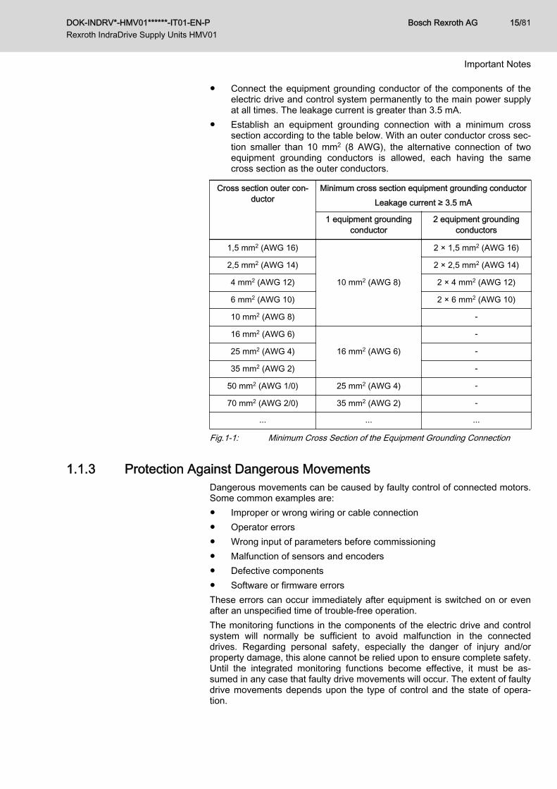
● Connect the equipment grounding conductor of the components of theelectric drive and control system permanently to the main power supplyat all times. The leakage current is greater than 3.5 mA.
● Establish an equipment grounding connection with a minimum crosssection according to the table below. With an outer conductor cross sec‐tion smaller than 10 mm2 (8 AWG), the alternative connection of twoequipment grounding conductors is allowed, each having the samecross section as the outer conductors.
Cross section outer con‐ductor
Minimum cross section equipment grounding conductorLeakage current ≥ 3.5 mA
1 equipment groundingconductor
2 equipment groundingconductors
1,5 mm2 (AWG 16)
10 mm2 (AWG 8)
2 × 1,5 mm2 (AWG 16)
2,5 mm2 (AWG 14) 2 × 2,5 mm2 (AWG 14)
4 mm2 (AWG 12) 2 × 4 mm2 (AWG 12)
6 mm2 (AWG 10) 2 × 6 mm2 (AWG 10)
10 mm2 (AWG 8) -
16 mm2 (AWG 6)
16 mm2 (AWG 6)
-
25 mm2 (AWG 4) -
35 mm2 (AWG 2) -
50 mm2 (AWG 1/0) 25 mm2 (AWG 4) -
70 mm2 (AWG 2/0) 35 mm2 (AWG 2) -
... ... ...
Fig.1-1: Minimum Cross Section of the Equipment Grounding Connection
1.1.3 Protection Against Dangerous MovementsDangerous movements can be caused by faulty control of connected motors.Some common examples are:● Improper or wrong wiring or cable connection● Operator errors● Wrong input of parameters before commissioning● Malfunction of sensors and encoders● Defective components● Software or firmware errorsThese errors can occur immediately after equipment is switched on or evenafter an unspecified time of trouble-free operation.The monitoring functions in the components of the electric drive and controlsystem will normally be sufficient to avoid malfunction in the connecteddrives. Regarding personal safety, especially the danger of injury and/orproperty damage, this alone cannot be relied upon to ensure complete safety.Until the integrated monitoring functions become effective, it must be as‐sumed in any case that faulty drive movements will occur. The extent of faultydrive movements depends upon the type of control and the state of opera‐tion.
DOK-INDRV*-HMV01******-IT01-EN-P Rexroth IndraDrive Supply Units HMV01
Bosch Rexroth AG 15/81
Important Notes
Dangerous movements! Danger to life, risk of injury, serious injury or propertydamage!A risk assessment must be prepared for the installation or machine, with itsspecific conditions, in which the components of the electric drive and controlsystem are installed.As a result of the risk assessment, the user must provide for monitoring func‐tions and higher-level measures on the installation side for personal safety.The safety regulations applicable to the installation or machine must be takeninto consideration. Unintended machine movements or other malfunctionsare possible if safety devices are disabled, bypassed or not activated.To avoid accidents, injury and/or property damage:● Keep free and clear of the machine’s range of motion and moving ma‐
chine parts. Prevent personnel from accidentally entering the machine’srange of motion by using, for example:– Safety fences– Safety guards– Protective coverings– Light barriers
● Make sure the safety fences and protective coverings are strong enoughto resist maximum possible kinetic energy.
● Mount emergency stopping switches in the immediate reach of the oper‐ator. Before commissioning, verify that the emergency stopping equip‐ment works. Do not operate the machine if the emergency stoppingswitch is not working.
● Prevent unintended start-up. Isolate the drive power connection bymeans of OFF switches/OFF buttons or use a safe starting lockout.
● Make sure that the drives are brought to safe standstill before accessingor entering the danger zone.
● Additionally secure vertical axes against falling or dropping after switch‐ing off the motor power by, for example,– mechanically securing the vertical axes,– adding an external braking/arrester/clamping mechanism or– ensuring sufficient counterbalancing of the vertical axes.
● The standard equipment motor holding brake or an external holdingbrake controlled by the drive controller is not sufficient to guarantee per‐sonal safety!
● Disconnect electrical power to the components of the electric drive andcontrol system using the master switch and secure them from reconnec‐tion ("lock out") for:– Maintenance and repair work– Cleaning of equipment– Long periods of discontinued equipment use
● Prevent the operation of high-frequency, remote control and radio equip‐ment near components of the electric drive and control system and theirsupply leads. If the use of these devices cannot be avoided, check themachine or installation, at initial commissioning of the electric drive andcontrol system, for possible malfunctions when operating such high-fre‐quency, remote control and radio equipment in its possible positions of
Bosch Rexroth AG DOK-INDRV*-HMV01******-IT01-EN-P Rexroth IndraDrive Supply Units HMV01
16/81
Important Notes
normal use. It might possibly be necessary to perform a special electro‐magnetic compatibility (EMC) test.
1.1.4 Protection Against Magnetic and Electromagnetic Fields During Oper‐ation and Mounting
Magnetic and electromagnetic fields generated by current-carrying conduc‐tors or permanent magnets of electric motors represent a serious danger topersons with heart pacemakers, metal implants and hearing aids.Health hazard for persons with heart pacemakers, metal implants and hear‐ing aids in proximity to electric components!● Persons with heart pacemakers and metal implants are not allowed to
enter the following areas:– Areas in which components of the electric drive and control sys‐
tems are mounted, commissioned and operated.– Areas in which parts of motors with permanent magnets are stored,
repaired or mounted.● If it is necessary for somebody with a heart pacemaker to enter such an
area, a doctor must be consulted prior to doing so. The noise immunityof implanted heart pacemakers differs so greatly that no general rulescan be given.
● Those with metal implants or metal pieces, as well as with hearing aids,must consult a doctor before they enter the areas described above.
1.1.5 Protection Against Contact With Hot PartsHot surfaces of components of the electric drive and control system. Risk ofburns!● Do not touch hot surfaces of, for example, braking resistors, heat sinks,
supply units and drive controllers, motors, windings and laminatedcores!
● According to the operating conditions, temperatures of the surfaces canbe higher than 60 °C (140 °F) during or after operation.
● Before touching motors after having switched them off, let them cooldown for a sufficient period of time. Cooling down can require up to 140minutes! The time required for cooling down is approximately five timesthe thermal time constant specified in the technical data.
● After switching chokes, supply units and drive controllers off, wait 15 mi‐nutes to allow them to cool down before touching them.
● Wear safety gloves or do not work at hot surfaces.● For certain applications, and in accordance with the respective safety
regulations, the manufacturer of the machine or installation must takemeasures to avoid injuries caused by burns in the final application.These measures can be, for example: Warnings at the machine or in‐stallation, guards (shieldings or barriers) or safety instructions in the ap‐plication documentation.
1.1.6 Protection During Handling and MountingRisk of injury by improper handling! Injury by crushing, shearing, cutting, hit‐ting!
DOK-INDRV*-HMV01******-IT01-EN-P Rexroth IndraDrive Supply Units HMV01
Bosch Rexroth AG 17/81
Important Notes
● Observe the relevant statutory regulations of accident prevention.● Use suitable equipment for mounting and transport.● Avoid jamming and crushing by appropriate measures.● Always use suitable tools. Use special tools if specified.● Use lifting equipment and tools in the correct manner.● Use suitable protective equipment (hard hat, safety goggles, safety
shoes, safety gloves, for example).● Do not stand under hanging loads.● Immediately clean up any spilled liquids from the floor due to the risk of
falling!
1.1.7 Battery SafetyBatteries consist of active chemicals in a solid housing. Therefore, improperhandling can cause injury or property damage.Risk of injury by improper handling!● Do not attempt to reactivate low batteries by heating or other methods
(risk of explosion and cauterization).● Do not attempt to recharge the batteries as this may cause leakage or
explosion.● Do not throw batteries into open flames.● Do not dismantle batteries.● When replacing the battery/batteries, do not damage the electrical parts
installed in the devices.● Only use the battery types specified for the product.
Environmental protection and disposal! The batteries contained inthe product are considered dangerous goods during land, air, andsea transport (risk of explosion) in the sense of the legal regula‐tions. Dispose of used batteries separately from other waste. Ob‐serve the national regulations of your country.
1.2 Appropriate UseThis product may only be used for the applications mentioned in the addition‐al documentations (see index entry "Additional documentations") and underthe described application, ambient and operating conditions.This product is exclusively intended for use in machines and systems in anindustrial environment. This is to be understood as applications according toIEC 60204-1 "Safety of machinery, Electric equipment of machines" andNFPA 79 "Electrical Standard for Industrial Machinery".
Bosch Rexroth AG DOK-INDRV*-HMV01******-IT01-EN-P Rexroth IndraDrive Supply Units HMV01
18/81
Important Notes

Components of the Rexroth IndraDrive system are products ofcategory C3 (with limited availability) according to IEC 61800‑3.To ensure that this category (limit values) is maintained, suitableline filters must be used in the drive system.These components are not provided for use in a public low-volt‐age network supplying residential areas with power. If these com‐ponents are used in such a public network, high-frequency inter‐ference is to be expected. This can require additional measuresof radio interference suppression.
DOK-INDRV*-HMV01******-IT01-EN-P Rexroth IndraDrive Supply Units HMV01
Bosch Rexroth AG 19/81
Important Notes

Bosch Rexroth AG DOK-INDRV*-HMV01******-IT01-EN-P Rexroth IndraDrive Supply Units HMV01
20/81
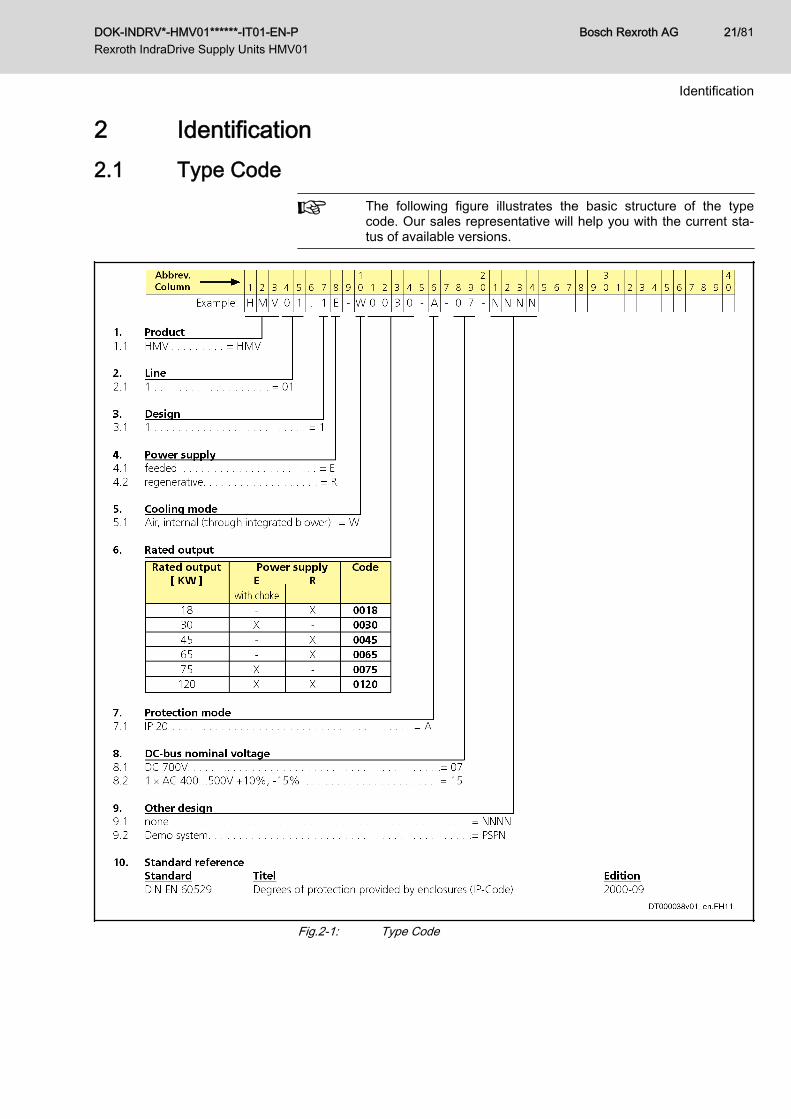
2 Identification2.1 Type Code
The following figure illustrates the basic structure of the typecode. Our sales representative will help you with the current sta‐tus of available versions.
Fig.2-1: Type Code
DOK-INDRV*-HMV01******-IT01-EN-P Rexroth IndraDrive Supply Units HMV01
Bosch Rexroth AG 21/81
Identification
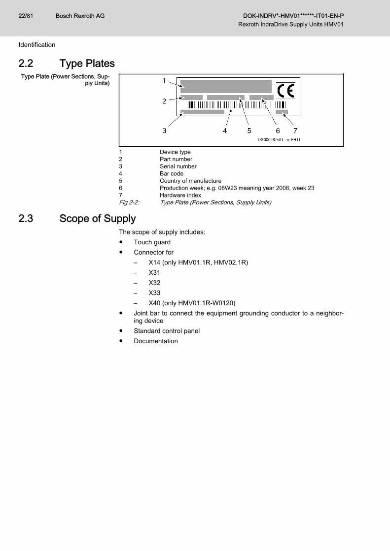
2.2 Type PlatesType Plate (Power Sections, Sup‐
ply Units)
1 Device type2 Part number3 Serial number4 Bar code5 Country of manufacture6 Production week; e.g. 08W23 meaning year 2008, week 237 Hardware indexFig.2-2: Type Plate (Power Sections, Supply Units)
2.3 Scope of SupplyThe scope of supply includes:● Touch guard● Connector for
– X14 (only HMV01.1R, HMV02.1R)– X31– X32– X33– X40 (only HMV01.1R-W0120)
● Joint bar to connect the equipment grounding conductor to a neighbor‐ing device
● Standard control panel● Documentation
Bosch Rexroth AG DOK-INDRV*-HMV01******-IT01-EN-P Rexroth IndraDrive Supply Units HMV01
22/81
Identification
3 Ratings and Dimensions3.1 HMV01.1E
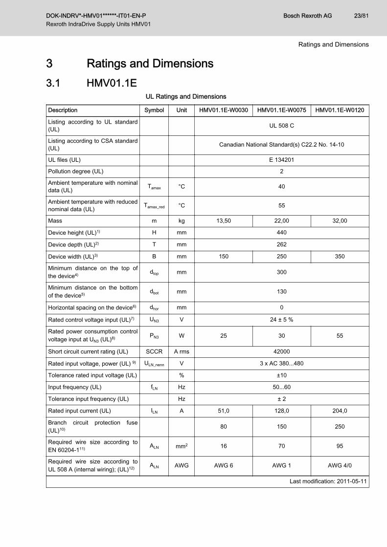
UL Ratings and Dimensions
Description Symbol Unit HMV01.1E-W0030 HMV01.1E-W0075 HMV01.1E-W0120
Listing according to UL standard(UL) UL 508 C
Listing according to CSA standard(UL) Canadian National Standard(s) C22.2 No. 14-10
UL files (UL) E 134201
Pollution degree (UL) 2
Ambient temperature with nominaldata (UL) Tamax °C 40
Ambient temperature with reducednominal data (UL) Tamax_red °C 55
Mass m kg 13,50 22,00 32,00
Device height (UL)1) H mm 440
Device depth (UL)2) T mm 262
Device width (UL)3) B mm 150 250 350
Minimum distance on the top ofthe device4) dtop mm 300
Minimum distance on the bottomof the device5) dbot mm 130
Horizontal spacing on the device6) dhor mm 0
Rated control voltage input (UL)7) UN3 V 24 ± 5 %
Rated power consumption controlvoltage input at UN3 (UL)8) PN3 W 25 30 55
Short circuit current rating (UL) SCCR A rms 42000
Rated input voltage, power (UL) 9) ULN_nenn V 3 x AC 380...480
Tolerance rated input voltage (UL) % ±10
Input frequency (UL) fLN Hz 50...60
Tolerance input frequency (UL) Hz ± 2
Rated input current (UL) ILN A 51,0 128,0 204,0
Branch circuit protection fuse(UL)10) 80 150 250
Required wire size according toEN 60204‑111) ALN mm2 16 70 95
Required wire size according toUL 508 A (internal wiring); (UL)12) ALN AWG AWG 6 AWG 1 AWG 4/0
Last modification: 2011-05-11
DOK-INDRV*-HMV01******-IT01-EN-P Rexroth IndraDrive Supply Units HMV01
Bosch Rexroth AG 23/81
Ratings and Dimensions
Description Symbol Unit HMV01.1E-W0030 HMV01.1E-W0075 HMV01.1E-W0120
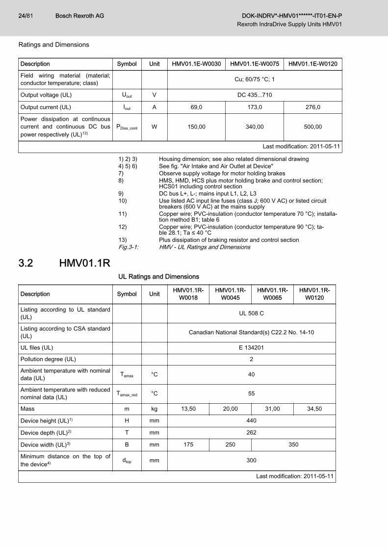
Field wiring material (material;conductor temperature; class) Cu; 60/75 °C; 1
Output voltage (UL) Uout V DC 435...710
Output current (UL) Iout A 69,0 173,0 276,0
Power dissipation at continuouscurrent and continuous DC buspower respectively (UL)13)
PDiss_cont W 150,00 340,00 500,00
Last modification: 2011-05-11
1) 2) 3) Housing dimension; see also related dimensional drawing4) 5) 6) See fig. "Air Intake and Air Outlet at Device"7) Observe supply voltage for motor holding brakes8) HMS, HMD, HCS plus motor holding brake and control section;
HCS01 including control section9) DC bus L+, L-; mains input L1, L2, L310) Use listed AC input line fuses (class J; 600 V AC) or listed circuit
breakers (600 V AC) at the mains supply11) Copper wire; PVC-insulation (conductor temperature 70 °C); installa‐
tion method B1; table 612) Copper wire; PVC-insulation (conductor temperature 90 °C); ta‐
ble 28.1; Ta ≤ 40 °C13) Plus dissipation of braking resistor and control sectionFig.3-1: HMV - UL Ratings and Dimensions
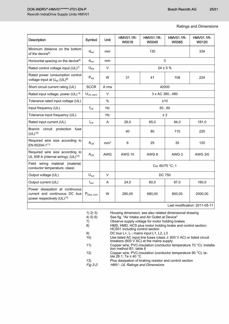
3.2 HMV01.1RUL Ratings and Dimensions
Description Symbol Unit HMV01.1R-W0018
HMV01.1R-W0045
HMV01.1R-W0065
HMV01.1R-W0120
Listing according to UL standard(UL) UL 508 C
Listing according to CSA standard(UL) Canadian National Standard(s) C22.2 No. 14-10
UL files (UL) E 134201
Pollution degree (UL) 2
Ambient temperature with nominaldata (UL) Tamax °C 40
Ambient temperature with reducednominal data (UL) Tamax_red °C 55
Mass m kg 13,50 20,00 31,00 34,50
Device height (UL)1) H mm 440
Device depth (UL)2) T mm 262
Device width (UL)3) B mm 175 250 350
Minimum distance on the top ofthe device4) dtop mm 300
Last modification: 2011-05-11
Bosch Rexroth AG DOK-INDRV*-HMV01******-IT01-EN-P Rexroth IndraDrive Supply Units HMV01
24/81
Ratings and Dimensions
Description Symbol Unit HMV01.1R-W0018
HMV01.1R-W0045
HMV01.1R-W0065
HMV01.1R-W0120
Minimum distance on the bottomof the device5) dbot mm 130 334
Horizontal spacing on the device6) dhor mm 0
Rated control voltage input (UL)7) UN3 V 24 ± 5 %
Rated power consumption controlvoltage input at UN3 (UL)8) PN3 W 31 41 108 224
Short circuit current rating (UL) SCCR A rms 42000
Rated input voltage, power (UL) 9) ULN_nenn V 3 x AC 380...480
Tolerance rated input voltage (UL) % ±10
Input frequency (UL) fLN Hz 50...60
Tolerance input frequency (UL) Hz ± 2
Rated input current (UL) ILN A 26,0 65,0 94,0 181,0
Branch circuit protection fuse(UL)10) 40 80 110 225
Required wire size according toEN 60204‑111) ALN mm2 6 25 35 120
Required wire size according toUL 508 A (internal wiring); (UL)12) ALN AWG AWG 10 AWG 6 AWG 3 AWG 3/0
Field wiring material (material;conductor temperature; class) Cu; 60/75 °C; 1
Output voltage (UL) Uout V DC 750
Output current (UL) Iout A 24,0 60,0 87,0 160,0
Power dissipation at continuouscurrent and continuous DC buspower respectively (UL)13)
PDiss_cont W 290,00 680,00 800,00 2000,00
Last modification: 2011-05-11
1) 2) 3) Housing dimension; see also related dimensional drawing4) 5) 6) See fig. "Air Intake and Air Outlet at Device"7) Observe supply voltage for motor holding brakes8) HMS, HMD, HCS plus motor holding brake and control section;
HCS01 including control section9) DC bus L+, L-; mains input L1, L2, L310) Use listed AC input line fuses (class J; 600 V AC) or listed circuit
breakers (600 V AC) at the mains supply11) Copper wire; PVC-insulation (conductor temperature 70 °C); installa‐
tion method B1; table 612) Copper wire; PVC-insulation (conductor temperature 90 °C); ta‐
ble 28.1; Ta ≤ 40 °C13) Plus dissipation of braking resistor and control sectionFig.3-2: HMV - UL Ratings and Dimensions
DOK-INDRV*-HMV01******-IT01-EN-P Rexroth IndraDrive Supply Units HMV01
Bosch Rexroth AG 25/81
Ratings and Dimensions
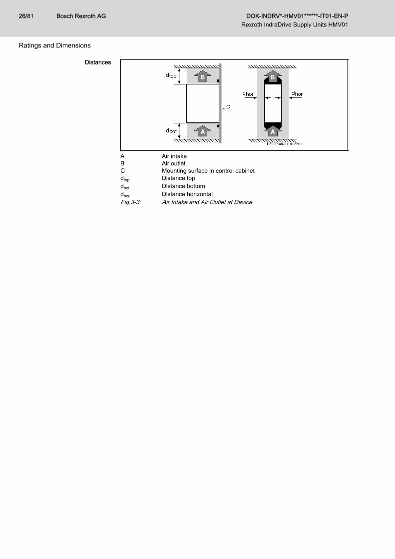
Distances
A Air intakeB Air outletC Mounting surface in control cabinetdtop Distance topdbot Distance bottomdhor Distance horizontalFig.3-3: Air Intake and Air Outlet at Device
Bosch Rexroth AG DOK-INDRV*-HMV01******-IT01-EN-P Rexroth IndraDrive Supply Units HMV01
26/81
Ratings and Dimensions
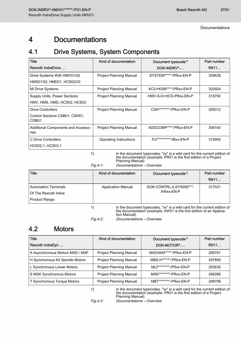
4 Documentations4.1 Drive Systems, System ComponentsTitleRexroth IndraDrive …
Kind of documentation Document typecode1)
DOK-INDRV*-…
Part numberR911…
Drive Systems With HMV01/02HMS01/02, HMD01, HCS02/03
Project Planning Manual SYSTEM*****-PRxx-EN-P 309636
Mi Drive Systems Project Planning Manual KCU+KSM****-PRxx-EN-P 320924
Supply Units, Power SectionsHMV, HMS, HMD, HCS02, HCS03
Project Planning Manual HMV-S-D+HCS-PRxx-EN-P 318790
Drive ControllersControl Sections CSB01, CSH01,CDB01
Project Planning Manual CSH********-PRxx-EN-P 295012
Additional Components and Accesso‐ries
Project Planning Manual ADDCOMP****-PRxx-EN-P 306140
C Drive ControllersHCS02.1, HCS03.1
Operating Instructions FU**********-IBxx-EN-P 314905
1) In the document typecodes, "xx" is a wild card for the current edition ofthe documentation (example: PR01 is the first edition of a ProjectPlanning Manual)
Fig.4-1: Documentations – Overview
Title Kind of documentation Document typecode1) Part numberR911…
Automation TerminalsOf The Rexroth InlineProduct Range
Application Manual DOK-CONTRL-ILSYSINS***-AWxx-EN-P
317021
1) In the document typecodes, "xx" is a wild card for the current edition ofthe documentation (example: AW01 is the first edition of an Applica‐tion Manual)
Fig.4-2: Documentations – Overview
4.2 MotorsTitleRexroth IndraDyn …
Kind of documentation Document typecode1)
DOK-MOTOR*-…
Part numberR911…
A Asynchronous Motors MAD / MAF Project Planning Manual MAD/MAF****-PRxx-EN-P 295781
H Synchronous Kit Spindle Motors Project Planning Manual MBS-H******-PRxx-EN-P 297895
L Synchronous Linear Motors Project Planning Manual MLF********-PRxx-EN-P 293635
S MSK Synchronous Motors Project Planning Manual MSK********-PRxx-EN-P 296289
T Synchronous Torque Motors Project Planning Manual MBT********-PRxx-EN-P 298798
1) In the document typecodes, "xx" is a wild card for the current edition ofthe documentation (example: PR01 is the first edition of a ProjectPlanning Manual)
Fig.4-3: Documentations – Overview
DOK-INDRV*-HMV01******-IT01-EN-P Rexroth IndraDrive Supply Units HMV01
Bosch Rexroth AG 27/81
Documentations
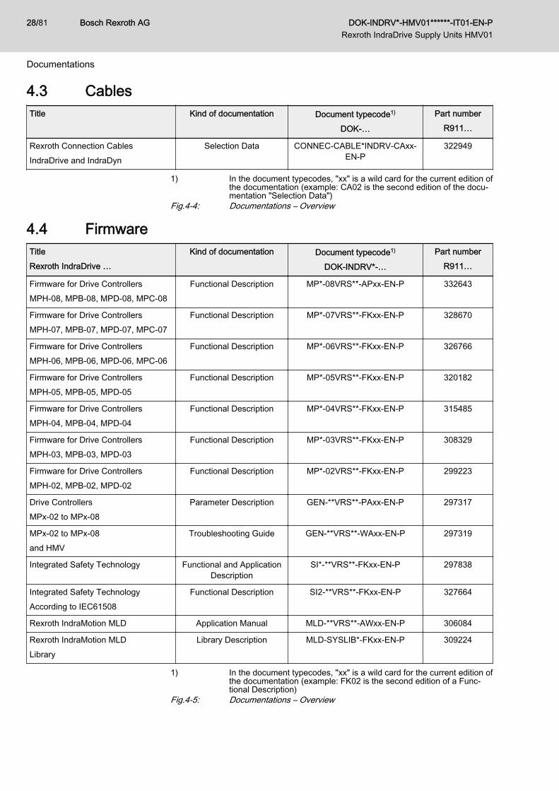
4.3 CablesTitle Kind of documentation Document typecode1)
DOK-…
Part numberR911…
Rexroth Connection CablesIndraDrive and IndraDyn
Selection Data CONNEC-CABLE*INDRV-CAxx-EN-P
322949
1) In the document typecodes, "xx" is a wild card for the current edition ofthe documentation (example: CA02 is the second edition of the docu‐mentation "Selection Data")
Fig.4-4: Documentations – Overview
4.4 FirmwareTitleRexroth IndraDrive …
Kind of documentation Document typecode1)
DOK-INDRV*-…
Part numberR911…
Firmware for Drive ControllersMPH-08, MPB-08, MPD-08, MPC-08
Functional Description MP*-08VRS**-APxx-EN-P 332643
Firmware for Drive ControllersMPH-07, MPB-07, MPD-07, MPC-07
Functional Description MP*-07VRS**-FKxx-EN-P 328670
Firmware for Drive ControllersMPH-06, MPB-06, MPD-06, MPC-06
Functional Description MP*-06VRS**-FKxx-EN-P 326766
Firmware for Drive ControllersMPH-05, MPB-05, MPD-05
Functional Description MP*-05VRS**-FKxx-EN-P 320182
Firmware for Drive ControllersMPH-04, MPB-04, MPD-04
Functional Description MP*-04VRS**-FKxx-EN-P 315485
Firmware for Drive ControllersMPH-03, MPB-03, MPD-03
Functional Description MP*-03VRS**-FKxx-EN-P 308329
Firmware for Drive ControllersMPH-02, MPB-02, MPD-02
Functional Description MP*-02VRS**-FKxx-EN-P 299223
Drive ControllersMPx-02 to MPx-08
Parameter Description GEN-**VRS**-PAxx-EN-P 297317
MPx-02 to MPx-08and HMV
Troubleshooting Guide GEN-**VRS**-WAxx-EN-P 297319
Integrated Safety Technology Functional and ApplicationDescription
SI*-**VRS**-FKxx-EN-P 297838
Integrated Safety TechnologyAccording to IEC61508
Functional Description SI2-**VRS**-FKxx-EN-P 327664
Rexroth IndraMotion MLD Application Manual MLD-**VRS**-AWxx-EN-P 306084
Rexroth IndraMotion MLDLibrary
Library Description MLD-SYSLIB*-FKxx-EN-P 309224
1) In the document typecodes, "xx" is a wild card for the current edition ofthe documentation (example: FK02 is the second edition of a Func‐tional Description)
Fig.4-5: Documentations – Overview
Bosch Rexroth AG DOK-INDRV*-HMV01******-IT01-EN-P Rexroth IndraDrive Supply Units HMV01
28/81
Documentations

Title Kind of documentation Document typecode1) Part numberR911…
Productivity AgentExtended Diagnostic Functions WithRexroth IndraDrive
Application Manual DOK-INDRV*-MLD-PAGENT*-AWxx-EN-P
323947
1) In the document typecodes, "xx" is a wild card for the current edition ofthe documentation (example: AW01 is the first edition of an Applica‐tion Manual)
Fig.4-6: Documentations – Overview
DOK-INDRV*-HMV01******-IT01-EN-P Rexroth IndraDrive Supply Units HMV01
Bosch Rexroth AG 29/81
Documentations

Bosch Rexroth AG DOK-INDRV*-HMV01******-IT01-EN-P Rexroth IndraDrive Supply Units HMV01
30/81
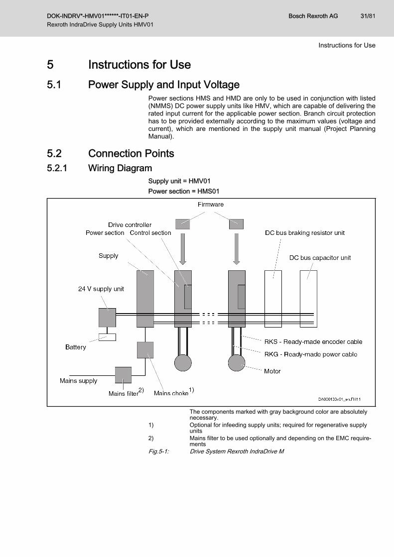
5 Instructions for Use5.1 Power Supply and Input Voltage
Power sections HMS and HMD are only to be used in conjunction with listed(NMMS) DC power supply units like HMV, which are capable of delivering therated input current for the applicable power section. Branch circuit protectionhas to be provided externally according to the maximum values (voltage andcurrent), which are mentioned in the supply unit manual (Project PlanningManual).
5.2 Connection Points5.2.1 Wiring Diagram
Supply unit = HMV01Power section = HMS01
The components marked with gray background color are absolutelynecessary.
1) Optional for infeeding supply units; required for regenerative supplyunits
2) Mains filter to be used optionally and depending on the EMC require‐ments
Fig.5-1: Drive System Rexroth IndraDrive M
DOK-INDRV*-HMV01******-IT01-EN-P Rexroth IndraDrive Supply Units HMV01
Bosch Rexroth AG 31/81
Instructions for Use
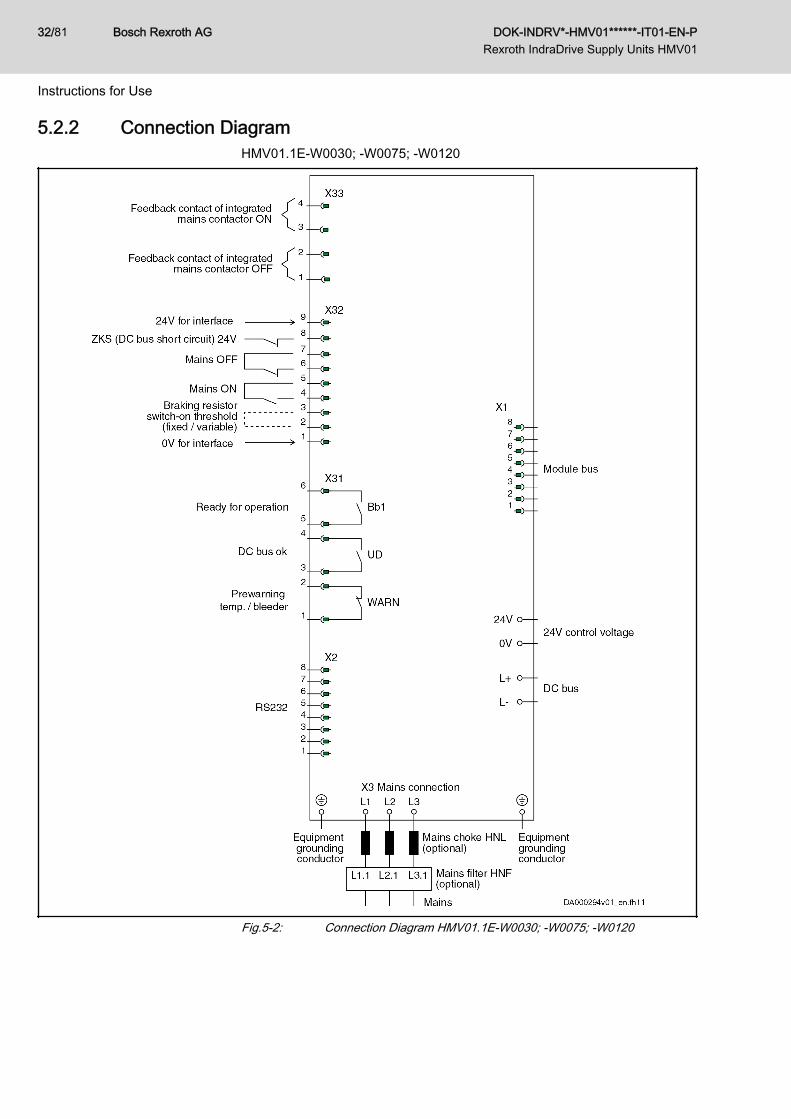
5.2.2 Connection DiagramHMV01.1E-W0030; -W0075; -W0120
Fig.5-2: Connection Diagram HMV01.1E-W0030; -W0075; -W0120
Bosch Rexroth AG DOK-INDRV*-HMV01******-IT01-EN-P Rexroth IndraDrive Supply Units HMV01
32/81
Instructions for Use
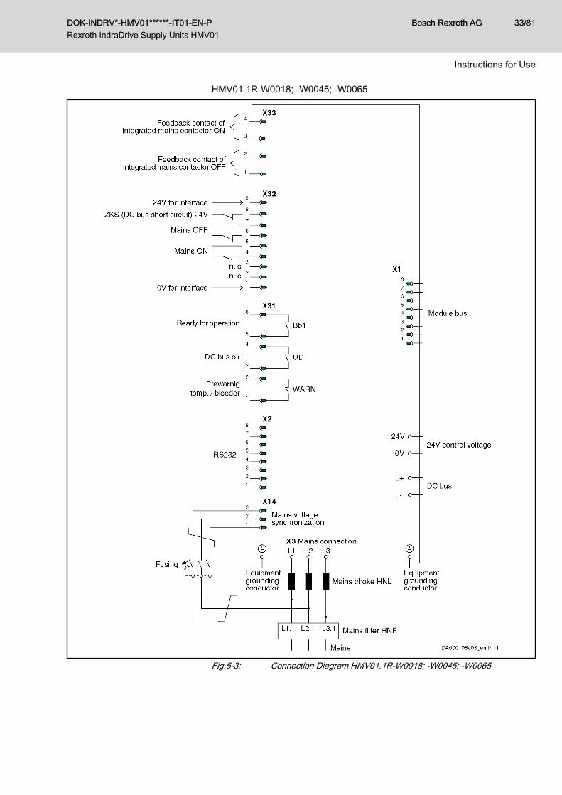
HMV01.1R-W0018; -W0045; -W0065
Fig.5-3: Connection Diagram HMV01.1R-W0018; -W0045; -W0065
DOK-INDRV*-HMV01******-IT01-EN-P Rexroth IndraDrive Supply Units HMV01
Bosch Rexroth AG 33/81
Instructions for Use
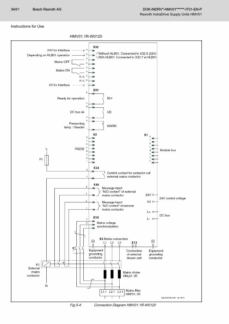
HMV01.1R-W0120
Fig.5-4: Connection Diagram HMV01.1R-W0120
Bosch Rexroth AG DOK-INDRV*-HMV01******-IT01-EN-P Rexroth IndraDrive Supply Units HMV01
34/81
Instructions for Use
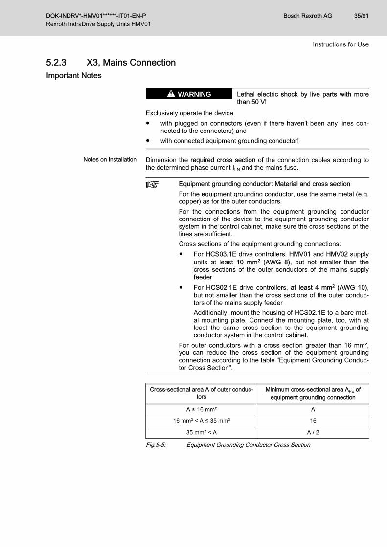
5.2.3 X3, Mains ConnectionImportant Notes
Lethal electric shock by live parts with morethan 50 V!
WARNING
Exclusively operate the device● with plugged on connectors (even if there haven't been any lines con‐
nected to the connectors) and● with connected equipment grounding conductor!
Notes on Installation Dimension the required cross section of the connection cables according tothe determined phase current ILN and the mains fuse.
Equipment grounding conductor: Material and cross sectionFor the equipment grounding conductor, use the same metal (e.g.copper) as for the outer conductors.For the connections from the equipment grounding conductorconnection of the device to the equipment grounding conductorsystem in the control cabinet, make sure the cross sections of thelines are sufficient.Cross sections of the equipment grounding connections:● For HCS03.1E drive controllers, HMV01 and HMV02 supply
units at least 10 mm2 (AWG 8), but not smaller than thecross sections of the outer conductors of the mains supplyfeeder
● For HCS02.1E drive controllers, at least 4 mm2 (AWG 10),but not smaller than the cross sections of the outer conduc‐tors of the mains supply feederAdditionally, mount the housing of HCS02.1E to a bare met‐al mounting plate. Connect the mounting plate, too, with atleast the same cross section to the equipment groundingconductor system in the control cabinet.
For outer conductors with a cross section greater than 16 mm²,you can reduce the cross section of the equipment groundingconnection according to the table "Equipment Grounding Conduc‐tor Cross Section".
Cross-sectional area A of outer conduc‐tors
Minimum cross-sectional area APE ofequipment grounding connection
A ≤ 16 mm² A
16 mm² < A ≤ 35 mm² 16
35 mm² < A A / 2
Fig.5-5: Equipment Grounding Conductor Cross Section
DOK-INDRV*-HMV01******-IT01-EN-P Rexroth IndraDrive Supply Units HMV01
Bosch Rexroth AG 35/81
Instructions for Use
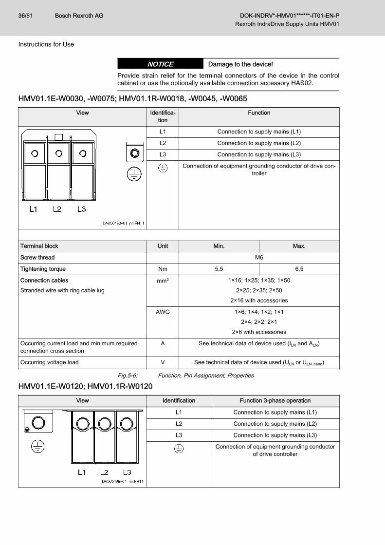
Damage to the device!NOTICEProvide strain relief for the terminal connectors of the device in the controlcabinet or use the optionally available connection accessory HAS02.
HMV01.1E-W0030, ‑W0075; HMV01.1R-W0018, ‑W0045, ‑W0065View Identifica‐
tionFunction
L1 Connection to supply mains (L1)
L2 Connection to supply mains (L2)
L3 Connection to supply mains (L3)
Connection of equipment grounding conductor of drive con‐troller
Terminal block Unit Min. Max.
Screw thread M6
Tightening torque Nm 5,5 6,5
Connection cablesStranded wire with ring cable lug
mm2 1×16; 1×25; 1×35; 1×502×25; 2×35; 2×50
2×16 with accessories
AWG 1×6; 1×4; 1×2; 1×12×4; 2×2; 2×1
2×6 with accessories
Occurring current load and minimum requiredconnection cross section
A See technical data of device used (ILN and ALN)
Occurring voltage load V See technical data of device used (ULN or ULN_nenn)
Fig.5-6: Function, Pin Assignment, Properties
HMV01.1E-W0120; HMV01.1R-W0120View Identification Function 3‑phase operation
L1 Connection to supply mains (L1)
L2 Connection to supply mains (L2)
L3 Connection to supply mains (L3)
Connection of equipment grounding conductorof drive controller
Bosch Rexroth AG DOK-INDRV*-HMV01******-IT01-EN-P Rexroth IndraDrive Supply Units HMV01
36/81
Instructions for Use
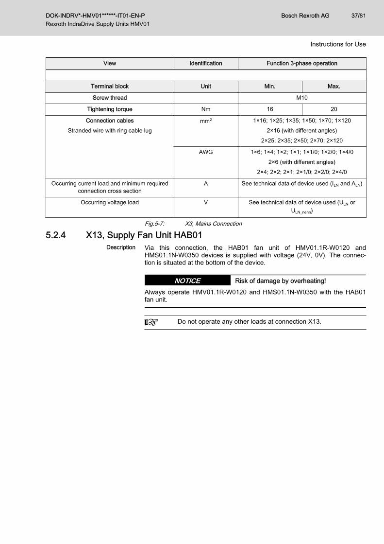
View Identification Function 3‑phase operation
Terminal block Unit Min. Max.
Screw thread M10
Tightening torque Nm 16 20
Connection cablesStranded wire with ring cable lug
mm2 1×16; 1×25; 1×35; 1×50; 1×70; 1×1202×16 (with different angles)
2×25; 2×35; 2×50; 2×70; 2×120
AWG 1×6; 1×4; 1×2; 1×1; 1×1/0; 1×2/0; 1×4/02×6 (with different angles)
2×4; 2×2; 2×1; 2×1/0; 2×2/0; 2×4/0
Occurring current load and minimum requiredconnection cross section
A See technical data of device used (ILN and ALN)
Occurring voltage load V See technical data of device used (ULN orULN_nenn)
Fig.5-7: X3, Mains Connection
5.2.4 X13, Supply Fan Unit HAB01Description Via this connection, the HAB01 fan unit of HMV01.1R‑W0120 and
HMS01.1N-W0350 devices is supplied with voltage (24V, 0V). The connec‐tion is situated at the bottom of the device.
Risk of damage by overheating!NOTICEAlways operate HMV01.1R-W0120 and HMS01.1N-W0350 with the HAB01fan unit.
Do not operate any other loads at connection X13.
DOK-INDRV*-HMV01******-IT01-EN-P Rexroth IndraDrive Supply Units HMV01
Bosch Rexroth AG 37/81
Instructions for Use
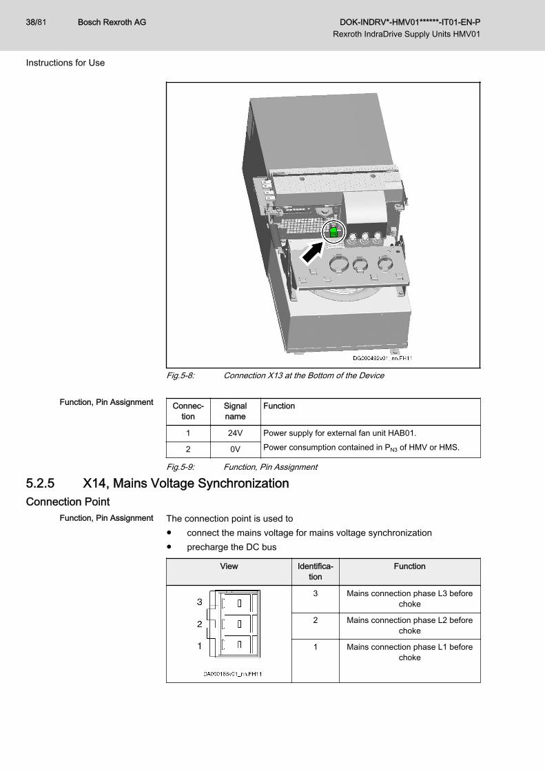
Fig.5-8: Connection X13 at the Bottom of the Device
Function, Pin Assignment Connec‐tion
Signalname
Function
1 24V Power supply for external fan unit HAB01.Power consumption contained in PN3 of HMV or HMS.2 0V
Fig.5-9: Function, Pin Assignment
5.2.5 X14, Mains Voltage SynchronizationConnection Point
Function, Pin Assignment The connection point is used to● connect the mains voltage for mains voltage synchronization● precharge the DC bus
View Identifica‐tion
Function
3 Mains connection phase L3 beforechoke
2 Mains connection phase L2 beforechoke
1 Mains connection phase L1 beforechoke
Bosch Rexroth AG DOK-INDRV*-HMV01******-IT01-EN-P Rexroth IndraDrive Supply Units HMV01
38/81
Instructions for Use
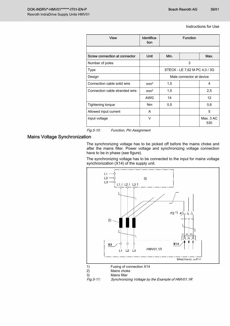
View Identifica‐tion
Function
Screw connection at connector Unit Min. Max.
Number of poles 3
Type STECK - LE 7,62 M PC 4,0 / 3G
Design Male connector at device
Connection cable solid wire mm2 1,5 4
Connection cable stranded wire mm2 1,5 2,5
AWG 14 12
Tightening torque Nm 0,5 0,6
Allowed input current A 5
Input voltage V Max. 3 AC530
Fig.5-10: Function, Pin Assignment
Mains Voltage SynchronizationThe synchronizing voltage has to be picked off before the mains choke andafter the mains filter. Power voltage and synchronizing voltage connectionhave to be in phase (see figure).The synchronizing voltage has to be connected to the input for mains voltagesynchronization (X14) of the supply unit.
1) Fusing of connection X142) Mains choke3) Mains filterFig.5-11: Synchronizing Voltage by the Example of HMV01.1R
DOK-INDRV*-HMV01******-IT01-EN-P Rexroth IndraDrive Supply Units HMV01
Bosch Rexroth AG 39/81
Instructions for Use
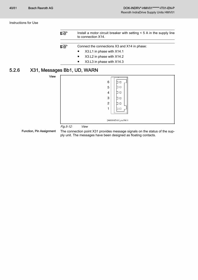
Install a motor circuit breaker with setting < 5 A in the supply lineto connection X14.
Connect the connections X3 and X14 in phase:● X3.L1 in phase with X14.1● X3.L2 in phase with X14.2● X3.L3 in phase with X14.3
5.2.6 X31, Messages Bb1, UD, WARNView
Fig.5-12: ViewFunction, Pin Assignment The connection point X31 provides message signals on the status of the sup‐
ply unit. The messages have been designed as floating contacts.
Bosch Rexroth AG DOK-INDRV*-HMV01******-IT01-EN-P Rexroth IndraDrive Supply Units HMV01
40/81
Instructions for Use
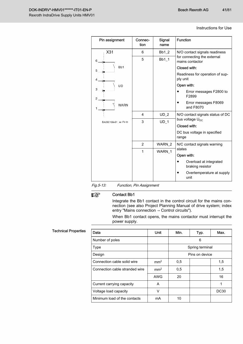
Pin assignment Connec‐tion
Signalname
Function
6 Bb1_2 N/O contact signals readinessfor connecting the externalmains contactorClosed with:Readiness for operation of sup‐ply unitOpen with:● Error messages F2800 to
F2899● Error messages F8069
and F8070
5 Bb1_1
4 UD_2 N/O contact signals status of DCbus voltage UDC
Closed with:DC bus voltage in specifiedrange
3 UD_1
2 WARN_2 N/C contact signals warningstatesOpen with:● Overload at integrated
braking resistor● Overtemperature at supply
unit
1 WARN_1
Fig.5-13: Function, Pin Assignment
Contact Bb1Integrate the Bb1 contact in the control circuit for the mains con‐nection (see also Project Planning Manual of drive system; indexentry "Mains connection → Control circuits").When Bb1 contact opens, the mains contactor must interrupt thepower supply.
Technical Properties Data Unit Min. Typ. Max.
Number of poles 6
Type Spring terminal
Design Pins on device
Connection cable solid wire mm2 0,5 1,5
Connection cable stranded wire mm2 0,5 1,5
AWG 20 16
Current carrying capacity A 1
Voltage load capacity V DC30
Minimum load of the contacts mA 10
DOK-INDRV*-HMV01******-IT01-EN-P Rexroth IndraDrive Supply Units HMV01
Bosch Rexroth AG 41/81
Instructions for Use

Data Unit Min. Typ. Max.
Contact resistance at minimumload
mOhm
Number of mechanical switchingcycles
106
Fig.5-14: Technical PropertiesNotes on Installation For the application prototypes of the supply units, the "WARN"
contact had been realized as N/O contact. From the followinghardware indices (HWIs) upwards, the "WARN" contact is realiz‐ed as N/C contact:● HMV01.1E-W0030: From HWI -14 upwards● HMV01.1E-W0075: From HWI -14 upwards● HMV01.1E-W0120: From HWI -15 upwards● HMV01.1R-W0018: From HWI -17 upwards● HMV01.1R-W0045: From HWI -17 upwards● HMV01.1R-W0065: From HWI -18 upwards
5.2.7 X32, Mains Contactor Control and DC Bus Short CircuitView
Fig.5-15: ViewFunction, Pin Assignment Is used to connect the signals for controlling
● the mains contactor● the ZKS stage (ZKS = DC bus short circuit)● the braking resistor switch-on threshold
Bosch Rexroth AG DOK-INDRV*-HMV01******-IT01-EN-P Rexroth IndraDrive Supply Units HMV01
42/81
Instructions for Use
Risk of fire caused by the "sacrificing behav‐ior" of the ZKS stage!
NOTICE
The "ZKS" input activates the function "DC bus short circuit", when therehasn't any voltage been applied and when there isn't any current flowing tothe input. This status occurs both in the case of wire break and when the 24Vsupply fails.When the 24V supply fails in applications in which energy does not only getto the DC bus via the mains connection, but also via regeneratively operatedmotors (e.g. following-on rollers), the ZKS stage converts this energy intoheat until it is destroyed ("sacrificing behavior").Counter measures with such applications:Buffer the 24V supply (e.g. by means of a UPS) to evaluate the monitor andswitch off the energy flow in the case of error.
DOK-INDRV*-HMV01******-IT01-EN-P Rexroth IndraDrive Supply Units HMV01
Bosch Rexroth AG 43/81
Instructions for Use
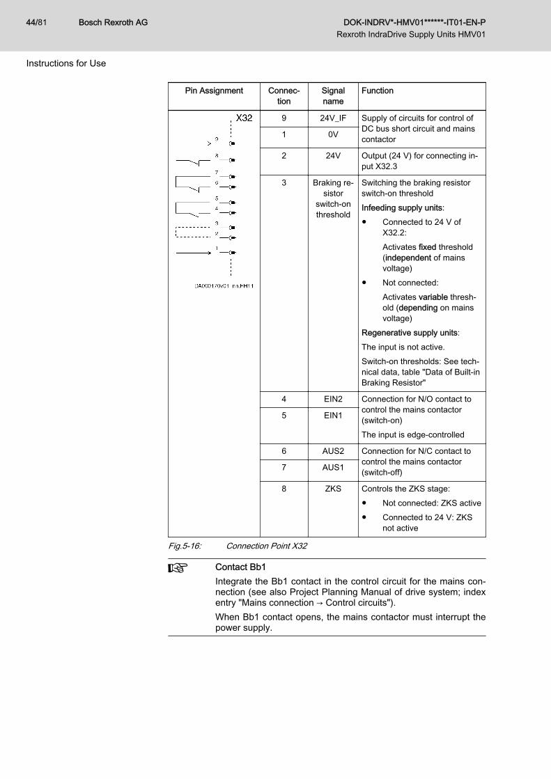
Pin Assignment Connec‐tion
Signalname
Function
9 24V_IF Supply of circuits for control ofDC bus short circuit and mainscontactor1 0V
2 24V Output (24 V) for connecting in‐put X32.3
3 Braking re‐sistor
switch-onthreshold
Switching the braking resistorswitch-on thresholdInfeeding supply units:● Connected to 24 V of
X32.2:Activates fixed threshold(independent of mainsvoltage)
● Not connected:Activates variable thresh‐old (depending on mainsvoltage)
Regenerative supply units:The input is not active.Switch-on thresholds: See tech‐nical data, table "Data of Built-inBraking Resistor"
4 EIN2 Connection for N/O contact tocontrol the mains contactor(switch-on)The input is edge-controlled
5 EIN1
6 AUS2 Connection for N/C contact tocontrol the mains contactor(switch-off)7 AUS1
8 ZKS Controls the ZKS stage:● Not connected: ZKS active● Connected to 24 V: ZKS
not active
Fig.5-16: Connection Point X32
Contact Bb1Integrate the Bb1 contact in the control circuit for the mains con‐nection (see also Project Planning Manual of drive system; indexentry "Mains connection → Control circuits").When Bb1 contact opens, the mains contactor must interrupt thepower supply.
Bosch Rexroth AG DOK-INDRV*-HMV01******-IT01-EN-P Rexroth IndraDrive Supply Units HMV01
44/81
Instructions for Use
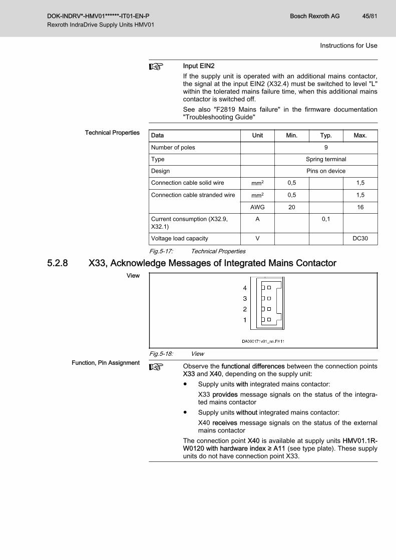
Input EIN2If the supply unit is operated with an additional mains contactor,the signal at the input EIN2 (X32.4) must be switched to level "L"within the tolerated mains failure time, when this additional mainscontactor is switched off.See also "F2819 Mains failure" in the firmware documentation"Troubleshooting Guide"
Technical Properties Data Unit Min. Typ. Max.
Number of poles 9
Type Spring terminal
Design Pins on device
Connection cable solid wire mm2 0,5 1,5
Connection cable stranded wire mm2 0,5 1,5
AWG 20 16
Current consumption (X32.9,X32.1)
A 0,1
Voltage load capacity V DC30
Fig.5-17: Technical Properties
5.2.8 X33, Acknowledge Messages of Integrated Mains ContactorView
Fig.5-18: ViewFunction, Pin Assignment Observe the functional differences between the connection points
X33 and X40, depending on the supply unit:● Supply units with integrated mains contactor:
X33 provides message signals on the status of the integra‐ted mains contactor
● Supply units without integrated mains contactor:X40 receives message signals on the status of the externalmains contactor
The connection point X40 is available at supply units HMV01.1R-W0120 with hardware index ≥ A11 (see type plate). These supplyunits do not have connection point X33.
DOK-INDRV*-HMV01******-IT01-EN-P Rexroth IndraDrive Supply Units HMV01
Bosch Rexroth AG 45/81
Instructions for Use
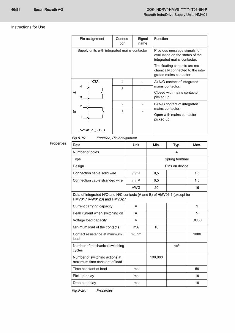
Pin assignment Connec‐tion
Signalname
Function
Supply units with integrated mains contactor Provides message signals forevaluation on the status of theintegrated mains contactor.The floating contacts are me‐chanically connected to the inte‐grated mains contactor.
4 - A) N/O contact of integratedmains contactor:Closed with mains contactorpicked up
3 -
2 - B) N/C contact of integratedmains contactor:Open with mains contactorpicked up
1 -
Fig.5-19: Function, Pin AssignmentProperties Data Unit Min. Typ. Max.
Number of poles 4
Type Spring terminal
Design Pins on device
Connection cable solid wire mm2 0,5 1,5
Connection cable stranded wire mm2 0,5 1,5
AWG 20 16
Data of integrated N/O and N/C contacts (A and B) of HMV01.1 (except forHMV01.1R-W0120) and HMV02.1
Current carrying capacity A 1
Peak current when switching on A 5
Voltage load capacity V DC30
Minimum load of the contacts mA 10
Contact resistance at minimumload
mOhm 1000
Number of mechanical switchingcycles
106
Number of switching actions atmaximum time constant of load
100.000
Time constant of load ms 50
Pick up delay ms 10
Drop out delay ms 10
Fig.5-20: Properties
Bosch Rexroth AG DOK-INDRV*-HMV01******-IT01-EN-P Rexroth IndraDrive Supply Units HMV01
46/81
Instructions for Use
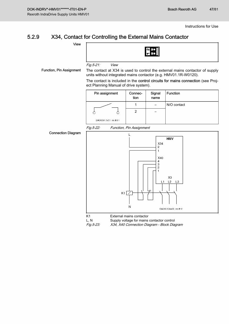
5.2.9 X34, Contact for Controlling the External Mains ContactorView
Fig.5-21: ViewFunction, Pin Assignment The contact at X34 is used to control the external mains contactor of supply
units without integrated mains contactor (e.g. HMV01.1R-W0120).The contact is included in the control circuits for mains connection (see Proj‐ect Planning Manual of drive system).
Pin assignment Connec‐tion
Signalname
Function
1 – N/O contact
2 –
Fig.5-22: Function, Pin AssignmentConnection Diagram
K1 External mains contactorL, N Supply voltage for mains contactor controlFig.5-23: X34, X40 Connection Diagram - Block Diagram
DOK-INDRV*-HMV01******-IT01-EN-P Rexroth IndraDrive Supply Units HMV01
Bosch Rexroth AG 47/81
Instructions for Use
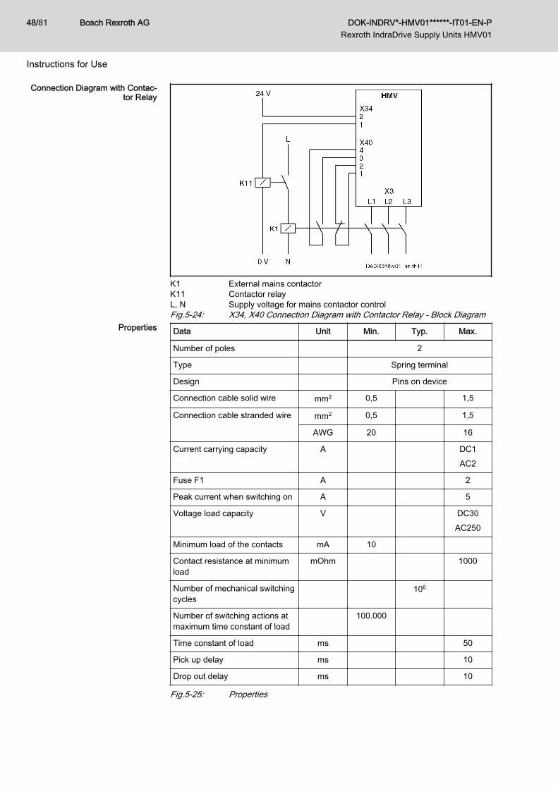
Connection Diagram with Contac‐tor Relay
K1 External mains contactorK11 Contactor relayL, N Supply voltage for mains contactor controlFig.5-24: X34, X40 Connection Diagram with Contactor Relay - Block Diagram
Properties Data Unit Min. Typ. Max.
Number of poles 2
Type Spring terminal
Design Pins on device
Connection cable solid wire mm2 0,5 1,5
Connection cable stranded wire mm2 0,5 1,5
AWG 20 16
Current carrying capacity A DC1AC2
Fuse F1 A 2
Peak current when switching on A 5
Voltage load capacity V DC30AC250
Minimum load of the contacts mA 10
Contact resistance at minimumload
mOhm 1000
Number of mechanical switchingcycles
106
Number of switching actions atmaximum time constant of load
100.000
Time constant of load ms 50
Pick up delay ms 10
Drop out delay ms 10
Fig.5-25: Properties
Bosch Rexroth AG DOK-INDRV*-HMV01******-IT01-EN-P Rexroth IndraDrive Supply Units HMV01
48/81
Instructions for Use
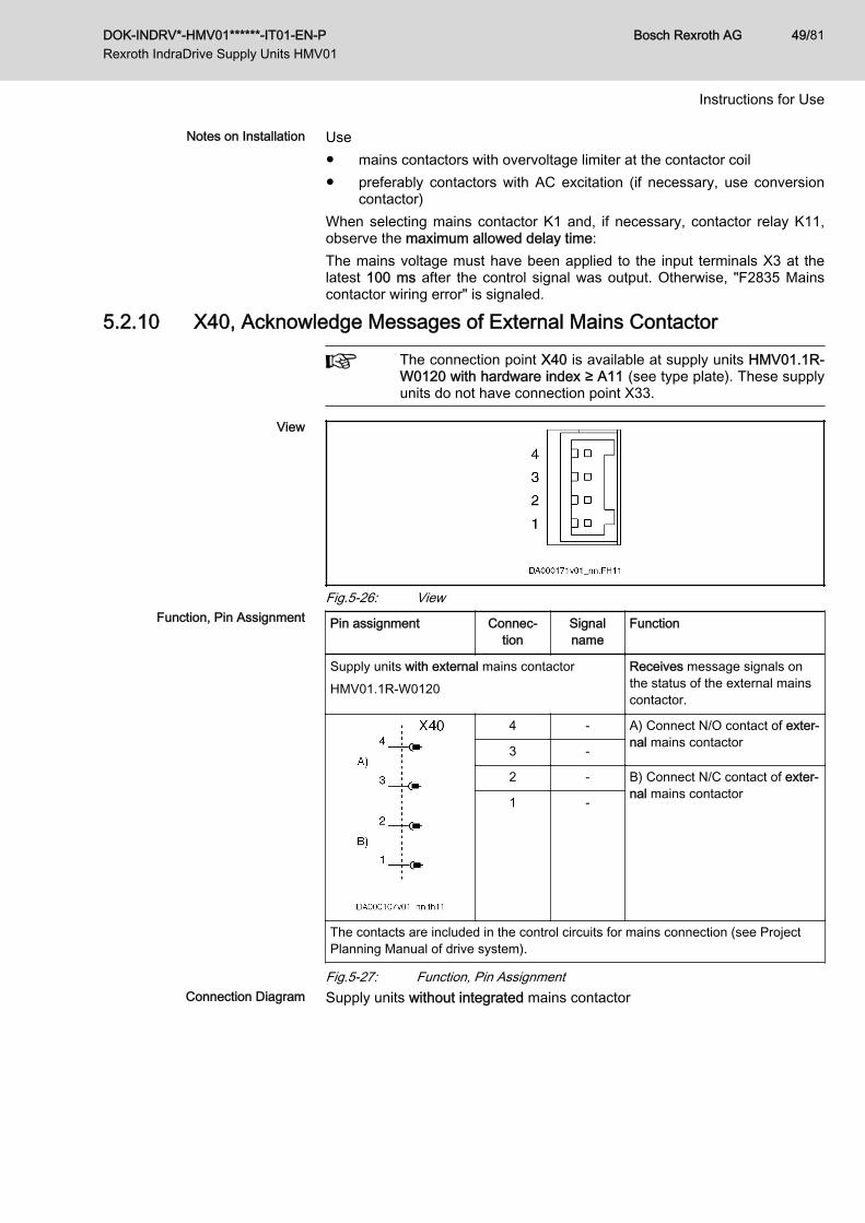
Notes on Installation Use● mains contactors with overvoltage limiter at the contactor coil● preferably contactors with AC excitation (if necessary, use conversion
contactor)When selecting mains contactor K1 and, if necessary, contactor relay K11,observe the maximum allowed delay time:The mains voltage must have been applied to the input terminals X3 at thelatest 100 ms after the control signal was output. Otherwise, "F2835 Mainscontactor wiring error" is signaled.
5.2.10 X40, Acknowledge Messages of External Mains Contactor
The connection point X40 is available at supply units HMV01.1R-W0120 with hardware index ≥ A11 (see type plate). These supplyunits do not have connection point X33.
View
Fig.5-26: ViewFunction, Pin Assignment Pin assignment Connec‐
tionSignalname
Function
Supply units with external mains contactorHMV01.1R-W0120
Receives message signals onthe status of the external mainscontactor.
4 - A) Connect N/O contact of exter‐nal mains contactor3 -
2 - B) Connect N/C contact of exter‐nal mains contactor1 -
The contacts are included in the control circuits for mains connection (see ProjectPlanning Manual of drive system).
Fig.5-27: Function, Pin AssignmentConnection Diagram Supply units without integrated mains contactor
DOK-INDRV*-HMV01******-IT01-EN-P Rexroth IndraDrive Supply Units HMV01
Bosch Rexroth AG 49/81
Instructions for Use
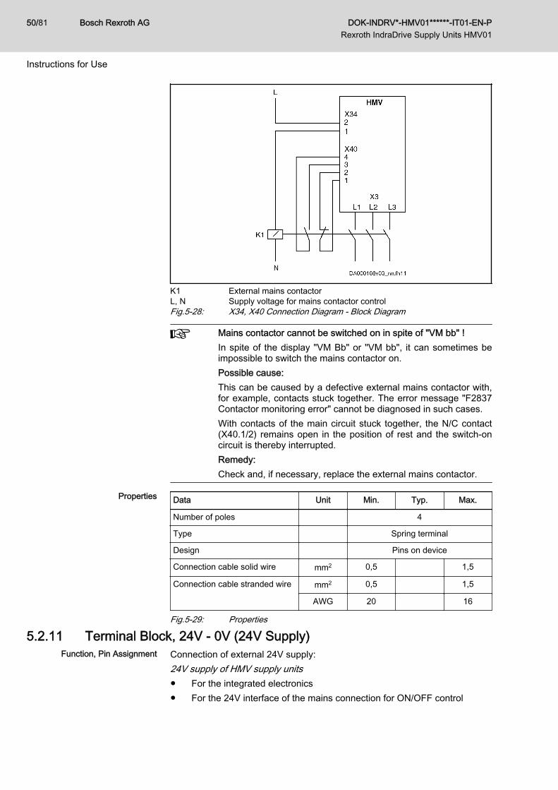
K1 External mains contactorL, N Supply voltage for mains contactor controlFig.5-28: X34, X40 Connection Diagram - Block Diagram
Mains contactor cannot be switched on in spite of "VM bb" !In spite of the display "VM Bb" or "VM bb", it can sometimes beimpossible to switch the mains contactor on.Possible cause:This can be caused by a defective external mains contactor with,for example, contacts stuck together. The error message "F2837Contactor monitoring error" cannot be diagnosed in such cases.With contacts of the main circuit stuck together, the N/C contact(X40.1/2) remains open in the position of rest and the switch-oncircuit is thereby interrupted.Remedy:Check and, if necessary, replace the external mains contactor.
Properties Data Unit Min. Typ. Max.
Number of poles 4
Type Spring terminal
Design Pins on device
Connection cable solid wire mm2 0,5 1,5
Connection cable stranded wire mm2 0,5 1,5
AWG 20 16
Fig.5-29: Properties
5.2.11 Terminal Block, 24V - 0V (24V Supply)Function, Pin Assignment Connection of external 24V supply:
24V supply of HMV supply units● For the integrated electronics● For the 24V interface of the mains connection for ON/OFF control
Bosch Rexroth AG DOK-INDRV*-HMV01******-IT01-EN-P Rexroth IndraDrive Supply Units HMV01
50/81
Instructions for Use
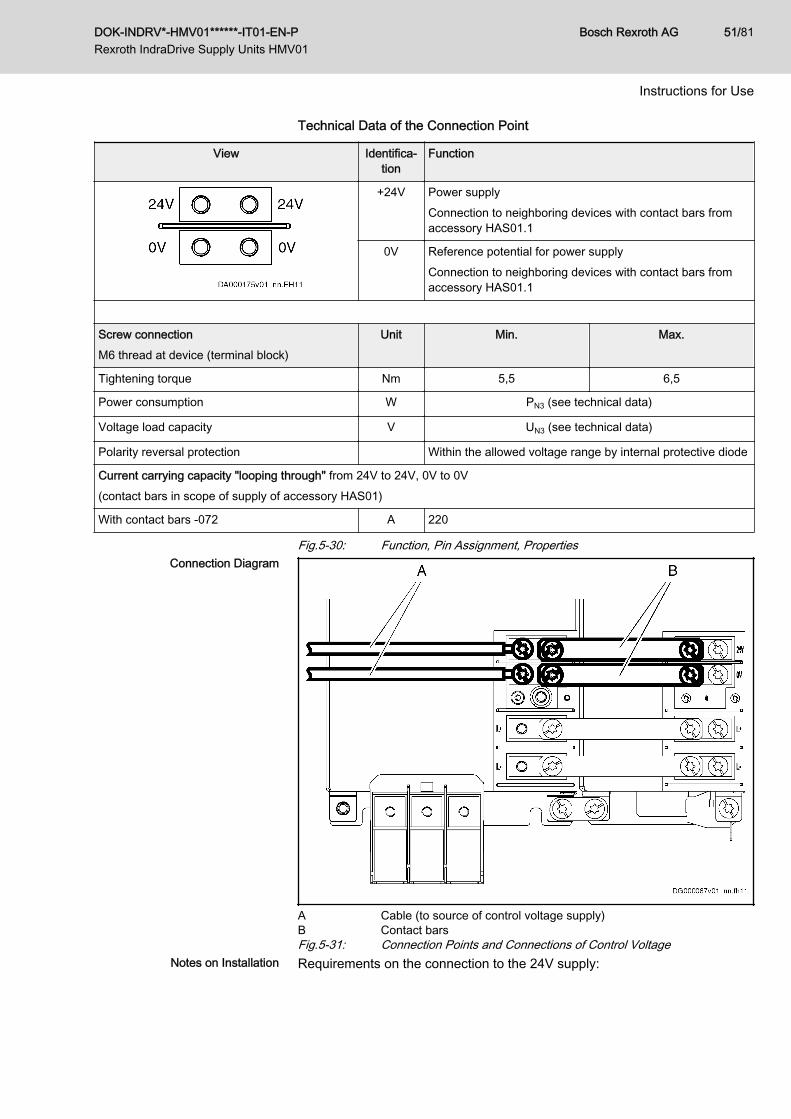
Technical Data of the Connection Point
View Identifica‐tion
Function
+24V Power supplyConnection to neighboring devices with contact bars fromaccessory HAS01.1
0V Reference potential for power supplyConnection to neighboring devices with contact bars fromaccessory HAS01.1
Screw connectionM6 thread at device (terminal block)
Unit Min. Max.
Tightening torque Nm 5,5 6,5
Power consumption W PN3 (see technical data)
Voltage load capacity V UN3 (see technical data)
Polarity reversal protection Within the allowed voltage range by internal protective diode
Current carrying capacity "looping through" from 24V to 24V, 0V to 0V(contact bars in scope of supply of accessory HAS01)
With contact bars -072 A 220
Fig.5-30: Function, Pin Assignment, PropertiesConnection Diagram
A Cable (to source of control voltage supply)B Contact barsFig.5-31: Connection Points and Connections of Control Voltage
Notes on Installation Requirements on the connection to the 24V supply:
DOK-INDRV*-HMV01******-IT01-EN-P Rexroth IndraDrive Supply Units HMV01
Bosch Rexroth AG 51/81
Instructions for Use
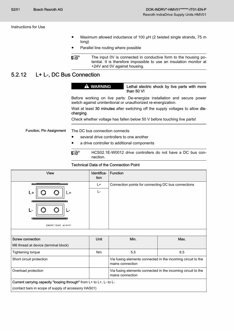
● Maximum allowed inductance of 100 µH (2 twisted single strands, 75 mlong)
● Parallel line routing where possible
The input 0V is connected in conductive form to the housing po‐tential. It is therefore impossible to use an insulation monitor at+24V and 0V against housing.
5.2.12 L+ L-, DC Bus Connection
Lethal electric shock by live parts with morethan 50 V!
WARNING
Before working on live parts: De-energize installation and secure powerswitch against unintentional or unauthorized re-energization.Wait at least 30 minutes after switching off the supply voltages to allow dis‐charging.Check whether voltage has fallen below 50 V before touching live parts!
Function, Pin Assignment The DC bus connection connects● several drive controllers to one another● a drive controller to additional components
HCS02.1E-W0012 drive controllers do not have a DC bus con‐nection.
Technical Data of the Connection Point
View Identifica‐tion
Function
L+ Connection points for connecting DC bus connections
L-
Screw connectionM6 thread at device (terminal block)
Unit Min. Max.
Tightening torque Nm 5,5 6,5
Short circuit protection Via fusing elements connected in the incoming circuit to themains connection
Overload protection Via fusing elements connected in the incoming circuit to themains connection
Current carrying capacity "looping through" from L+ to L+, L- to L-(contact bars in scope of supply of accessory HAS01)
Bosch Rexroth AG DOK-INDRV*-HMV01******-IT01-EN-P Rexroth IndraDrive Supply Units HMV01
52/81
Instructions for Use
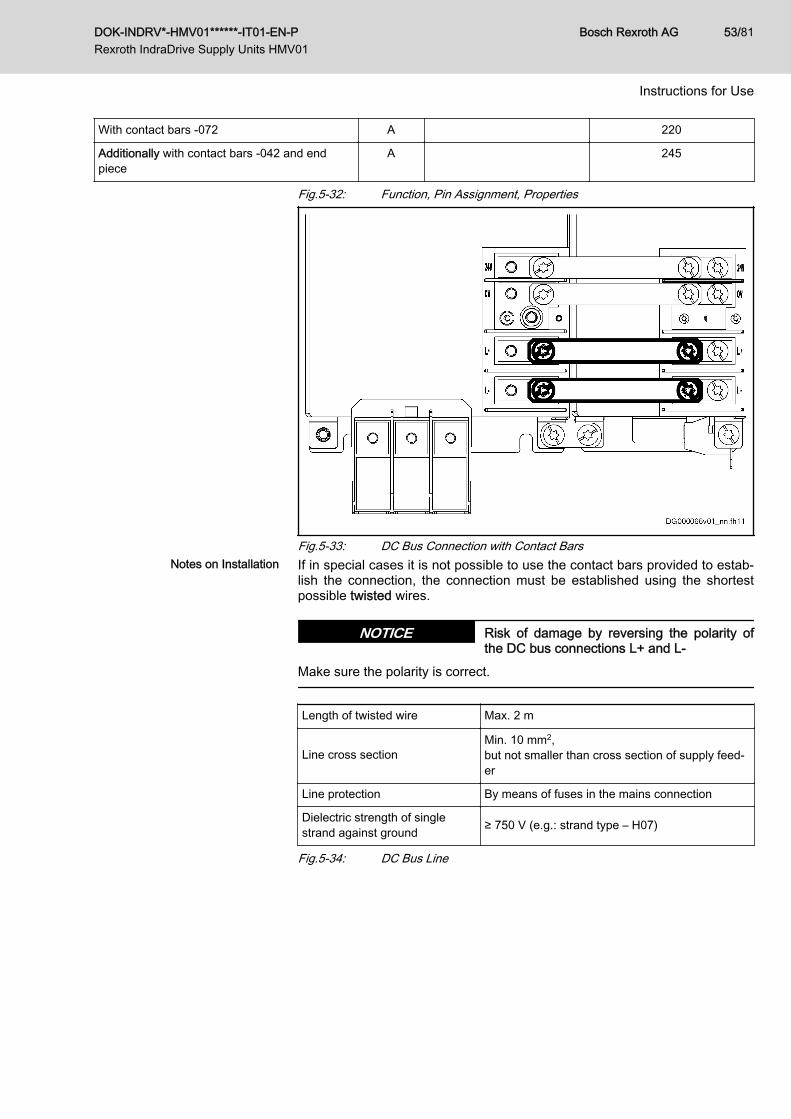
With contact bars -072 A 220
Additionally with contact bars ‑042 and endpiece
A 245
Fig.5-32: Function, Pin Assignment, Properties
Fig.5-33: DC Bus Connection with Contact BarsNotes on Installation If in special cases it is not possible to use the contact bars provided to estab‐
lish the connection, the connection must be established using the shortestpossible twisted wires.
Risk of damage by reversing the polarity ofthe DC bus connections L+ and L-
NOTICE
Make sure the polarity is correct.
Length of twisted wire Max. 2 m
Line cross sectionMin. 10 mm2, but not smaller than cross section of supply feed‐er
Line protection By means of fuses in the mains connection
Dielectric strength of singlestrand against ground ≥ 750 V (e.g.: strand type – H07)
Fig.5-34: DC Bus Line
DOK-INDRV*-HMV01******-IT01-EN-P Rexroth IndraDrive Supply Units HMV01
Bosch Rexroth AG 53/81
Instructions for Use
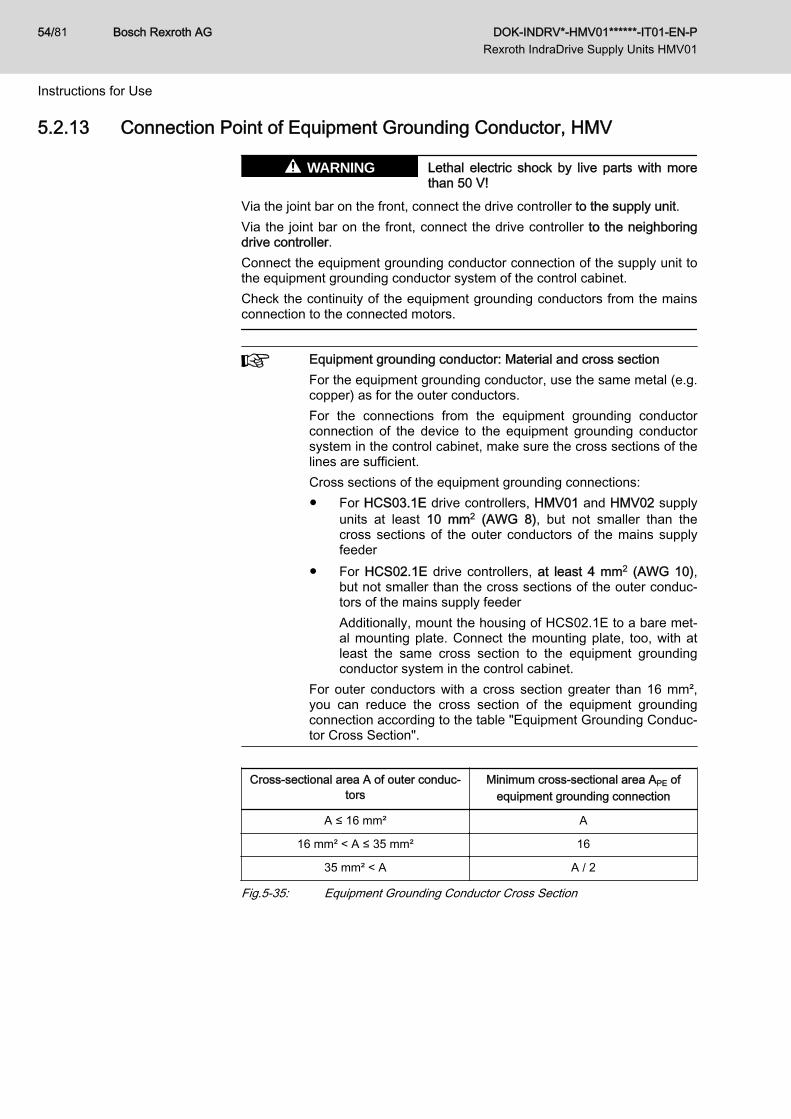
5.2.13 Connection Point of Equipment Grounding Conductor, HMV
Lethal electric shock by live parts with morethan 50 V!
WARNING
Via the joint bar on the front, connect the drive controller to the supply unit.Via the joint bar on the front, connect the drive controller to the neighboringdrive controller.Connect the equipment grounding conductor connection of the supply unit tothe equipment grounding conductor system of the control cabinet.Check the continuity of the equipment grounding conductors from the mainsconnection to the connected motors.
Equipment grounding conductor: Material and cross sectionFor the equipment grounding conductor, use the same metal (e.g.copper) as for the outer conductors.For the connections from the equipment grounding conductorconnection of the device to the equipment grounding conductorsystem in the control cabinet, make sure the cross sections of thelines are sufficient.Cross sections of the equipment grounding connections:● For HCS03.1E drive controllers, HMV01 and HMV02 supply
units at least 10 mm2 (AWG 8), but not smaller than thecross sections of the outer conductors of the mains supplyfeeder
● For HCS02.1E drive controllers, at least 4 mm2 (AWG 10),but not smaller than the cross sections of the outer conduc‐tors of the mains supply feederAdditionally, mount the housing of HCS02.1E to a bare met‐al mounting plate. Connect the mounting plate, too, with atleast the same cross section to the equipment groundingconductor system in the control cabinet.
For outer conductors with a cross section greater than 16 mm²,you can reduce the cross section of the equipment groundingconnection according to the table "Equipment Grounding Conduc‐tor Cross Section".
Cross-sectional area A of outer conduc‐tors
Minimum cross-sectional area APE ofequipment grounding connection
A ≤ 16 mm² A
16 mm² < A ≤ 35 mm² 16
35 mm² < A A / 2
Fig.5-35: Equipment Grounding Conductor Cross Section
Bosch Rexroth AG DOK-INDRV*-HMV01******-IT01-EN-P Rexroth IndraDrive Supply Units HMV01
54/81
Instructions for Use
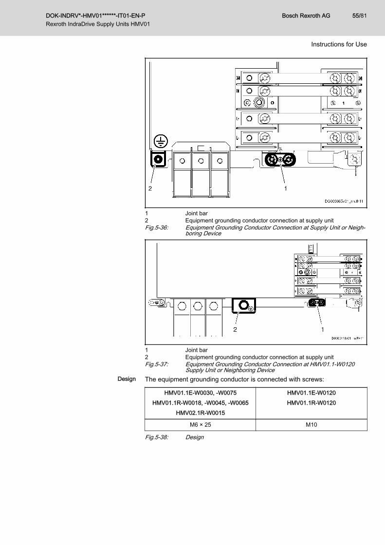
1 Joint bar2 Equipment grounding conductor connection at supply unitFig.5-36: Equipment Grounding Conductor Connection at Supply Unit or Neigh‐
boring Device
1 Joint bar2 Equipment grounding conductor connection at supply unitFig.5-37: Equipment Grounding Conductor Connection at HMV01.1-W0120
Supply Unit or Neighboring DeviceDesign The equipment grounding conductor is connected with screws:
HMV01.1E-W0030, -W0075HMV01.1R-W0018, -W0045, -W0065
HMV02.1R-W0015
HMV01.1E-W0120HMV01.1R-W0120
M6 × 25 M10
Fig.5-38: Design
DOK-INDRV*-HMV01******-IT01-EN-P Rexroth IndraDrive Supply Units HMV01
Bosch Rexroth AG 55/81
Instructions for Use
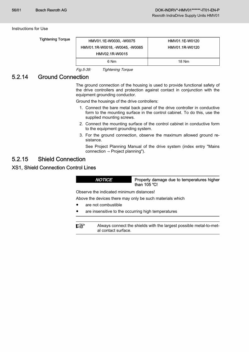
Tightening Torque HMV01.1E-W0030, -W0075HMV01.1R-W0018, -W0045, -W0065
HMV02.1R-W0015
HMV01.1E-W0120HMV01.1R-W0120
6 Nm 18 Nm
Fig.5-39: Tightening Torque
5.2.14 Ground ConnectionThe ground connection of the housing is used to provide functional safety ofthe drive controllers and protection against contact in conjunction with theequipment grounding conductor.Ground the housings of the drive controllers:
1. Connect the bare metal back panel of the drive controller in conductiveform to the mounting surface in the control cabinet. To do this, use thesupplied mounting screws.
2. Connect the mounting surface of the control cabinet in conductive formto the equipment grounding system.
3. For the ground connection, observe the maximum allowed ground re‐sistance.See Project Planning Manual of the drive system (index entry "Mainsconnection → Project planning").
5.2.15 Shield ConnectionXS1, Shield Connection Control Lines
Property damage due to temperatures higherthan 105 ℃!
NOTICE
Observe the indicated minimum distances!Above the devices there may only be such materials which● are not combustible● are insensitive to the occurring high temperatures
Always connect the shields with the largest possible metal-to-met‐al contact surface.
Bosch Rexroth AG DOK-INDRV*-HMV01******-IT01-EN-P Rexroth IndraDrive Supply Units HMV01
56/81
Instructions for Use
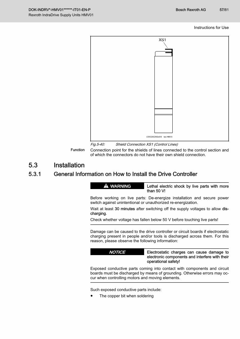
Fig.5-40: Shield Connection XS1 (Control Lines)Function Connection point for the shields of lines connected to the control section and
of which the connectors do not have their own shield connection.
5.3 Installation5.3.1 General Information on How to Install the Drive Controller
Lethal electric shock by live parts with morethan 50 V!
WARNING
Before working on live parts: De-energize installation and secure powerswitch against unintentional or unauthorized re-energization.Wait at least 30 minutes after switching off the supply voltages to allow dis‐charging.Check whether voltage has fallen below 50 V before touching live parts!
Damage can be caused to the drive controller or circuit boards if electrostaticcharging present in people and/or tools is discharged across them. For thisreason, please observe the following information:
Electrostatic charges can cause damage toelectronic components and interfere with theiroperational safety!
NOTICE
Exposed conductive parts coming into contact with components and circuitboards must be discharged by means of grounding. Otherwise errors may oc‐cur when controlling motors and moving elements.
Such exposed conductive parts include:● The copper bit when soldering
DOK-INDRV*-HMV01******-IT01-EN-P Rexroth IndraDrive Supply Units HMV01
Bosch Rexroth AG 57/81
Instructions for Use
● The human body (ground connection by touching a conductive, groun‐ded object)
● Parts and tools (place them on a conductive support)Endangered components may only be stored or dispatched in conductivepackaging.
Rexroth connection diagrams are only to be used for producinginstallation circuit diagrams! The machine manufacturer’s installa‐tion circuit diagrams must be used for wiring the installation!
● Lay signal lines separately from the load resistance lines because of theoccurrence of interference.
● Transmit analog signals (e.g. command values, actual values) via shiel‐ded lines.
● Do not connect mains, DC bus or power cores to low voltages or allowthem to come into contact with these.
● When carrying out a high voltage test or an applied-overvoltage with‐stand test on the machine’s electrical equipment, disconnect all connec‐tions to the devices. This protects the electronic components (allowed inaccordance with EN 60204-1). During their routine testing, Rexroth drivecomponents are tested for high voltage (in accordance with EN61800-5-1:2007, section 5.2.3.2) and insulation (in accordance with EN60204-1:2006, section 18.3).
Risk of damage to the drive controller by con‐necting and disconnecting live connections!
NOTICE
Do not connect and disconnect live connections.
5.3.2 Sizing of Enclosure and Control CabinetMultiple-Line Design of the Control Cabinet
Arrangement of the devices, air guides/drip protections, fansPay particular attention to the maximum allowed air intake tem‐perature of devices when they are arranged in multiple lines in thecontrol cabinet.If possible, place devices with a high degree of power dissipation(e.g. supply units with braking resistors, DC bus resistor units)● in the top line and● near the outlet air aperture to the cooling unitMount air guides between the lines to● protect the devices in the upper lines against the warm outlet
air of the devices beneath and● protect the devices beneath against penetration of liquids
(e.g. dripping condensation water or leaking cooling liquid)Additional fans convey the outlet air to the cooling unit and cool‐ing air to the upper lines.At the installed control cabinet, check the air intake temperatureof all devices.
Bosch Rexroth AG DOK-INDRV*-HMV01******-IT01-EN-P Rexroth IndraDrive Supply Units HMV01
58/81
Instructions for Use
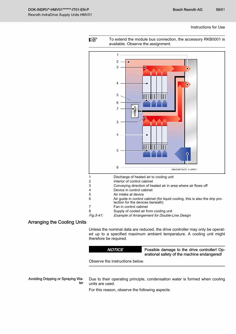
To extend the module bus connection, the accessory RKB0001 isavailable. Observe the assignment.
1 Discharge of heated air to cooling unit2 Interior of control cabinet3 Conveying direction of heated air in area where air flows off4 Device in control cabinet5 Air intake at device6 Air guide in control cabinet (for liquid cooling, this is also the drip pro‐
tection for the devices beneath)7 Fan in control cabinet8 Supply of cooled air from cooling unitFig.5-41: Example of Arrangement for Double-Line Design
Arranging the Cooling UnitsUnless the nominal data are reduced, the drive controller may only be operat‐ed up to a specified maximum ambient temperature. A cooling unit mighttherefore be required.
Possible damage to the drive controller! Op‐erational safety of the machine endangered!
NOTICE
Observe the instructions below.
Avoiding Dripping or Spraying Wa‐
terDue to their operating principle, condensation water is formed when coolingunits are used.For this reason, observe the following aspects:
DOK-INDRV*-HMV01******-IT01-EN-P Rexroth IndraDrive Supply Units HMV01
Bosch Rexroth AG 59/81
Instructions for Use
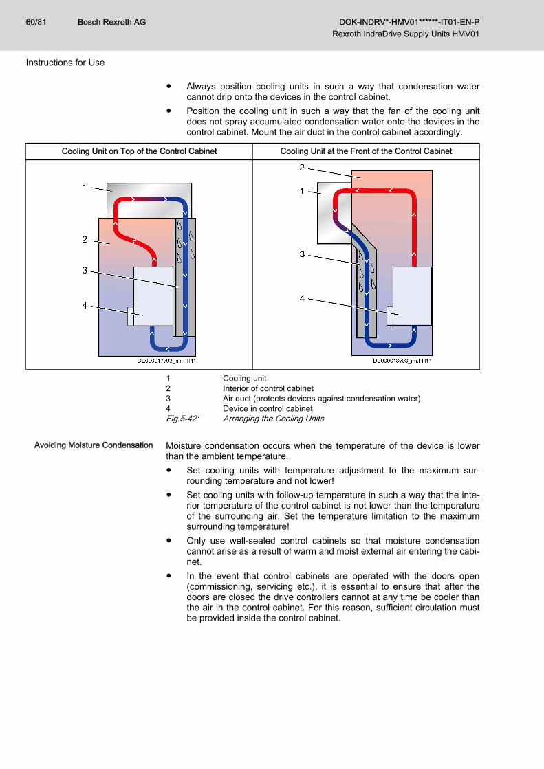
● Always position cooling units in such a way that condensation watercannot drip onto the devices in the control cabinet.
● Position the cooling unit in such a way that the fan of the cooling unitdoes not spray accumulated condensation water onto the devices in thecontrol cabinet. Mount the air duct in the control cabinet accordingly.
Cooling Unit on Top of the Control Cabinet Cooling Unit at the Front of the Control Cabinet
1 Cooling unit2 Interior of control cabinet3 Air duct (protects devices against condensation water)4 Device in control cabinetFig.5-42: Arranging the Cooling Units
Avoiding Moisture Condensation Moisture condensation occurs when the temperature of the device is lowerthan the ambient temperature.● Set cooling units with temperature adjustment to the maximum sur‐
rounding temperature and not lower!● Set cooling units with follow-up temperature in such a way that the inte‐
rior temperature of the control cabinet is not lower than the temperatureof the surrounding air. Set the temperature limitation to the maximumsurrounding temperature!
● Only use well-sealed control cabinets so that moisture condensationcannot arise as a result of warm and moist external air entering the cabi‐net.
● In the event that control cabinets are operated with the doors open(commissioning, servicing etc.), it is essential to ensure that after thedoors are closed the drive controllers cannot at any time be cooler thanthe air in the control cabinet. For this reason, sufficient circulation mustbe provided inside the control cabinet.
Bosch Rexroth AG DOK-INDRV*-HMV01******-IT01-EN-P Rexroth IndraDrive Supply Units HMV01
60/81
Instructions for Use
6 EMC Measures for Design and Installation6.1 Rules for Design of Installations With Drive Controllers in
Compliance With EMCThe following rules are the basics for designing and installing drives in com‐pliance with EMC.
Mains filter Correctly use a mains filter recommended by Rexroth for radio interferencesuppression in the supply feeder of the drive system.
Control Cabinet Grounding Connect all metal parts of the cabinet with one another over the largest possi‐ble surface area to establish a good electrical connection. This, too, appliesto the mounting of the mains filter. If required, use serrated washers whichcut through the paint surface. Connect the cabinet door to the control cabinetusing the shortest possible grounding straps.
Line Routing Avoid coupling routes between lines with high potential of noise and noise-free lines; therefore, signal, mains and motor lines and power cables have tobe routed separately from another. Minimum distance: 10 cm. Provide sepa‐rating sheets between power and signal lines. Ground separating sheets sev‐eral times.The lines with high potential of noise include:● Lines at the mains connection (incl. synchronization connection)● Lines at the motor connection● Lines at the DC bus connectionGenerally, interference injections are reduced by routing cables close togrounded sheet steel plates. For this reason, cables and wires should not berouted freely in the cabinet, but close to the cabinet housing or mounting pan‐els. Separate the incoming and outgoing cables of the radio interference sup‐pression filter.
Interference Suppression Ele‐ments
Provide the following components in the control cabinet with interference sup‐pression combinations:● Contactors● Relays● Solenoid valves● Electromechanical operating hours countersConnect these combinations directly at each coil.
Twisted Wires Twist unshielded wires belonging to the same circuit (feeder and return ca‐ble) or keep the surface between feeder and return cable as small as possi‐ble. Wires that are not used have to be grounded at both ends.
Lines of Measuring Systems Lines of measuring systems must be shielded. Connect the shield to groundat both ends and over the largest possible surface area. The shield may notbe interrupted, e.g. using intermediate terminals.
Digital Signal Lines Ground the shields of digital signal lines at both ends (transmitter and receiv‐er) over the largest possible surface area and with low impedance. In thecase of bad ground connection between transmitter and receiver, additionallyroute a bonding conductor (min. 10 mm2). Braided shields are better than foilshields.
Analog Signal Lines Ground the shields of analog signal lines at one end (transmitter or receiver)over the largest possible surface area and with low impedance. This avoidslow-frequency interference current (in the mains frequency range) on theshield.
DOK-INDRV*-HMV01******-IT01-EN-P Rexroth IndraDrive Supply Units HMV01
Bosch Rexroth AG 61/81
EMC Measures for Design and Installation
Connecting the Mains Choke Keep connection lines of the mains choke at the drive controller as short aspossible and twist them.
Installing the Motor Power Cable ● Use shielded motor power cables or run motor power cables in a shiel‐ded duct
● Use the shortest possible motor power cables● Ground shield of motor power cable at both ends over the largest possi‐
ble surface area to establish a good electrical connection● Run motor lines in shielded form inside the control cabinet● Do not use any steel-shielded lines● The shield of the motor power cable mustn't be interrupted by mounted
components, such as output chokes, sine filters or motor filters
6.2 EMC-Optimal Installation in Facility and Control Cabinet6.2.1 General Information
For EMC-optimal installation, a spatial separation of the interference-freearea (mains connection) and the interference-susceptible area (drive compo‐nents) is recommended, as shown in the figures below.
Recommendation: For EMC-optimal installation in the control cab‐inet, use a separate control cabinet panel for the drive compo‐nents.
6.2.2 Division Into Areas (Zones)Exemplary arrangements in the control cabinet: See section Control CabinetDesign According to Interference Areas - Exemplary Arrangements,page 63.We distinguish three areas:
1. Interference-free area of control cabinet (area A):This includes:● Supply feeder, input terminals, fuse, main switch, mains side of
mains filter for drives and corresponding connecting lines● Control voltage or auxiliary voltage connection with power supply
unit, fuse and other parts unless connection is run via the mains fil‐ter of the AC drives
● All components that are not electrically connected with the drivesystem
2. Interference-susceptible area (area B):● Mains connections between drive system and mains filter for
drives, mains contactor● Interface lines of drive controller
3. Strongly interference-susceptible area (area C):● Motor power cables including single cores
Never run lines of one of these areas in parallel with lines of another area sothat there isn't any unwanted interference injection from one area to the otherand that the filter is jumpered with regard to high frequency. Use the shortestpossible connecting lines.
Bosch Rexroth AG DOK-INDRV*-HMV01******-IT01-EN-P Rexroth IndraDrive Supply Units HMV01
62/81
EMC Measures for Design and Installation
Recommendation for complex systems: Install drive components in one cabi‐net and the control units in a second, separate cabinet.Badly grounded control cabinet doors act as antennas. Therefore, connectthe control cabinet doors to the cabinet on top, in the middle and on the bot‐tom via short equipment grounding conductors with a cross section of at least6 mm2 or, even better, via grounding straps with the same cross section.Make sure connection points have good contact.
6.2.3 Control Cabinet Design According to Interference Areas - ExemplaryArrangements
Supply Units With Regeneration Do not operate any additional loads at the mains filter!Do not operate any other loads at the connection from the mainsfilter output to the mains connection of the supply unit.For motor fans and power supply units, for example, use separatemains filters.
DOK-INDRV*-HMV01******-IT01-EN-P Rexroth IndraDrive Supply Units HMV01
Bosch Rexroth AG 63/81
EMC Measures for Design and Installation
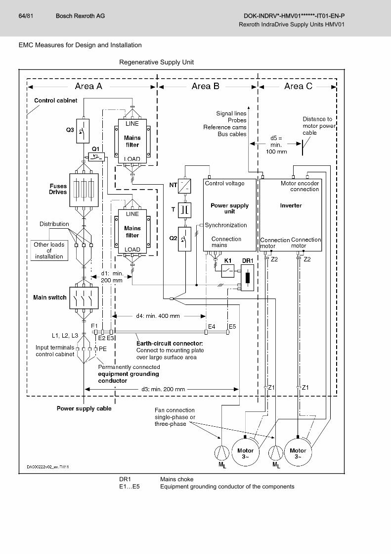
Regenerative Supply Unit
DR1 Mains chokeE1…E5 Equipment grounding conductor of the components
Bosch Rexroth AG DOK-INDRV*-HMV01******-IT01-EN-P Rexroth IndraDrive Supply Units HMV01
64/81
EMC Measures for Design and Installation

K1 External mains contactor for supply units without integrated mainscontactor
ML Motor fanNT Power supply unitQ1, Q2, Q3 FusingT TransformerZ1, Z2 Shield connection points for cablesFig.6-1: Regenerative Supply Unit – EMC Areas in the Control Cabinet
DOK-INDRV*-HMV01******-IT01-EN-P Rexroth IndraDrive Supply Units HMV01
Bosch Rexroth AG 65/81
EMC Measures for Design and Installation
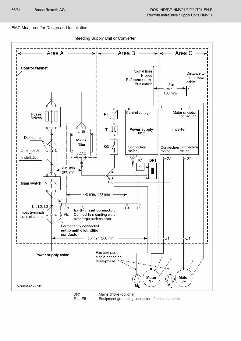
Infeeding Supply Unit or Converter
DR1 Mains choke (optional)E1…E5 Equipment grounding conductor of the components
Bosch Rexroth AG DOK-INDRV*-HMV01******-IT01-EN-P Rexroth IndraDrive Supply Units HMV01
66/81
EMC Measures for Design and Installation
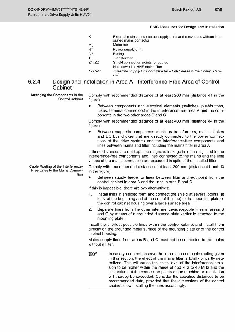
K1 External mains contactor for supply units and converters without inte‐grated mains contactor
ML Motor fanNT Power supply unitQ2 FusingT TransformerZ1, Z2 Shield connection points for cables* Not allowed at HNF mains filterFig.6-2: Infeeding Supply Unit or Converter – EMC Areas in the Control Cabi‐
net
6.2.4 Design and Installation in Area A - Interference-Free Area of ControlCabinet
Arranging the Components in theControl Cabinet
Comply with recommended distance of at least 200 mm (distance d1 in thefigure):● Between components and electrical elements (switches, pushbuttons,
fuses, terminal connectors) in the interference-free area A and the com‐ponents in the two other areas B and C
Comply with recommended distance of at least 400 mm (distance d4 in thefigure):● Between magnetic components (such as transformers, mains chokes
and DC bus chokes that are directly connected to the power connec‐tions of the drive system) and the interference-free components andlines between mains and filter including the mains filter in area A
If these distances are not kept, the magnetic leakage fields are injected to theinterference-free components and lines connected to the mains and the limitvalues at the mains connection are exceeded in spite of the installed filter.
Cable Routing of the Interference-Free Lines to the Mains Connec‐
tion
Comply with recommended distance of at least 200 mm (distance d1 and d3in the figure):● Between supply feeder or lines between filter and exit point from the
control cabinet in area A and the lines in area B and CIf this is impossible, there are two alternatives:1. Install lines in shielded form and connect the shield at several points (at
least at the beginning and at the end of the line) to the mounting plate orthe control cabinet housing over a large surface area.
2. Separate lines from the other interference-susceptible lines in areas Band C by means of a grounded distance plate vertically attached to themounting plate.
Install the shortest possible lines within the control cabinet and install themdirectly on the grounded metal surface of the mounting plate or of the controlcabinet housing.Mains supply lines from areas B and C must not be connected to the mainswithout a filter.
In case you do not observe the information on cable routing givenin this section, the effect of the mains filter is totally or partly neu‐tralized. This will cause the noise level of the interference emis‐sion to be higher within the range of 150 kHz to 40 MHz and thelimit values at the connection points of the machine or installationwill thereby be exceeded. Consider the specified distances to berecommended data, provided that the dimensions of the controlcabinet allow installing the lines accordingly.
DOK-INDRV*-HMV01******-IT01-EN-P Rexroth IndraDrive Supply Units HMV01
Bosch Rexroth AG 67/81
EMC Measures for Design and Installation
Routing and Connecting a NeutralConductor (N)
If a neutral conductor is used together with a three-phase connection, it mustnot be installed unfiltered in zones B and C, in order to keep interference offthe mains.
Motor Fan at Mains Filter Single-phase or three-phase supply lines of motor fans, that are usually rout‐ed in parallel with motor power cables or interference-susceptible lines, mustbe filtered:● In drive systems with regenerative supply units, via a separate single-
phase (NFE type) or three-phase filter (HNF type) near the mains con‐nection of the control cabinet
● In drive systems with only infeeding supply units, via the available three-phase filter of the drive system
When switching power off, make sure the fan is not switched off.When switching power off, make sure the fan is not switched off.
Loads at Mains Filter of Drive Sys‐tem Only operate allowed loads at the mains filter of the drive system!
At the three-phase filter for the power connection of regenerativesupply units, it is only allowed to operate the following loads:● HMV supply unit with mains choke and, if necessary, mains
contactorDo not operate any motor fans, power supply units etc. at themains filter of the drive system.
Shielding Mains Supply Lines inControl Cabinet
If there is a high degree of interference injection to the mains supply line with‐in the control cabinet, although you have observed the above instructions (tobe found out by EMC measurement according to standard), proceed as fol‐lows:● Only use shielded lines in area A● Connect shields to the mounting plate at the beginning and the end of
the line by means of clipsThe same procedure may be required for long cables of more than 2 m be‐tween the point of power supply connection of the control cabinet and the fil‐ter within the control cabinet.
Mains Filters for AC Drives Ideally mount the mains filter on the parting line between the areas A and B.Make sure the ground connection between filter housing and housing of thedrive controllers has good electrically conductive properties.If single-phase loads are connected on the load side of the filter, their currentmay be a maximum of 10% of the three-phase operating current. A highly im‐balanced load of the filter would deteriorate its interference suppression ca‐pacity.If the mains voltage is more than 480 V, connect the filter to the output side ofthe transformer and not to the supply side of the transformer.
Grounding In the case of bad ground connections in the installation, the distance be‐tween the lines to the grounding points E1, E2 in area A and the othergrounding points of the drive system should be at least d4 = 400 mm, in orderto minimize interference injection from ground and ground cables to the pow‐er input lines.See also 6.2.2 Division Into Areas (Zones), page 62.
Point of Connection for EquipmentGrounding Conductor at Machine,
Installation, Control Cabinet
The equipment grounding conductor of the power cable of the machine, in‐stallation or control cabinet has to be permanently connected at point PE andhave a cross section of at least 10 mm2 or to be complemented by a secondequipment grounding conductor via separate terminal connectors (accordingto EN 61800-5-1:2007, section 4.3.5.5.2). If the cross section of the outer
Bosch Rexroth AG DOK-INDRV*-HMV01******-IT01-EN-P Rexroth IndraDrive Supply Units HMV01
68/81
EMC Measures for Design and Installation
conductor is bigger, the cross section of the equipment grounding conductormust be accordingly bigger.
6.2.5 Design and Installation in Area B - Interference-Susceptible Area ofControl Cabinet
Arranging Components and Lines Modules, components and lines in area B should be placed at a distance ofat least d1 = 200 mm from modules and lines in area A.Alternative: Shield modules, components and lines in area B by distanceplates mounted vertically on the mounting plate from modules and lines inarea A or use shielded lines.Only connect power supply units for auxiliary or control voltage connectionsin the drive system to the mains via a mains filter. See 6.2.2 Division IntoAreas (Zones), page 62.Install the shortest possible lines between drive controller and filter.
Control Voltage or Auxiliary Volt‐age Connection
Only in exceptional cases should you connect power supply unit and fusingfor the control voltage connection to phase and neutral conductor. In thiscase, mount and install these components in area A far away from the areasB and C of the drive system. For details see section 6.2.4 Design and Instal‐lation in Area A - Interference-Free Area of Control Cabinet, page 67.Run the connection between control voltage connection of the drive systemand power supply unit used through area B over the shortest distance.
Line Routing Run the lines along grounded metal surfaces, in order to minimize radiationof interference fields to area A (transmitting antenna effect).
6.2.6 Design and Installation in Area C - Strongly Interference-SusceptibleArea of Control Cabinet
Area C mainly concerns the motor power cables, especially at the connectionpoint at the drive controller.
Influence of the Motor Power Ca‐ble
The longer the motor power cable, the greater its leakage capacitance. Tocomply with a certain EMC limit value, the allowed leakage capacitance ofthe mains filter is limited. For the calculation of the leakage capacitance, seethe documentation on the drive system of the drive controller used.
● Run the shortest possible motor power cables.● Only use shielded motor power cables by Rexroth.
Routing the Motor Power Cablesand Motor Encoder Cables
Route the motor power cables and motor encoder cables along groundedmetal surfaces, both inside the control cabinet and outside of it, in order tominimize radiation of interference fields. If possible, route the motor powercables and motor encoder cables in metal-grounded cable ducts.Route the motor power cables and motor encoder cables● with a distance of at least d5 = 100 mm to interference-free lines, as
well as to signal cables and signal lines(alternatively separated by a grounded distance plate)
● in separate cable ducts, if possibleRouting the Motor Power Cables
and Mains Connection LinesFor converters (drive controllers with individual mains connection), route mo‐tor power cables and (unfiltered) mains connection lines in parallel for a maxi‐mum distance of 300 mm. After that distance, route motor power cables andpower supply cables in opposite directions and preferably in separate cableducts.
DOK-INDRV*-HMV01******-IT01-EN-P Rexroth IndraDrive Supply Units HMV01
Bosch Rexroth AG 69/81
EMC Measures for Design and Installation
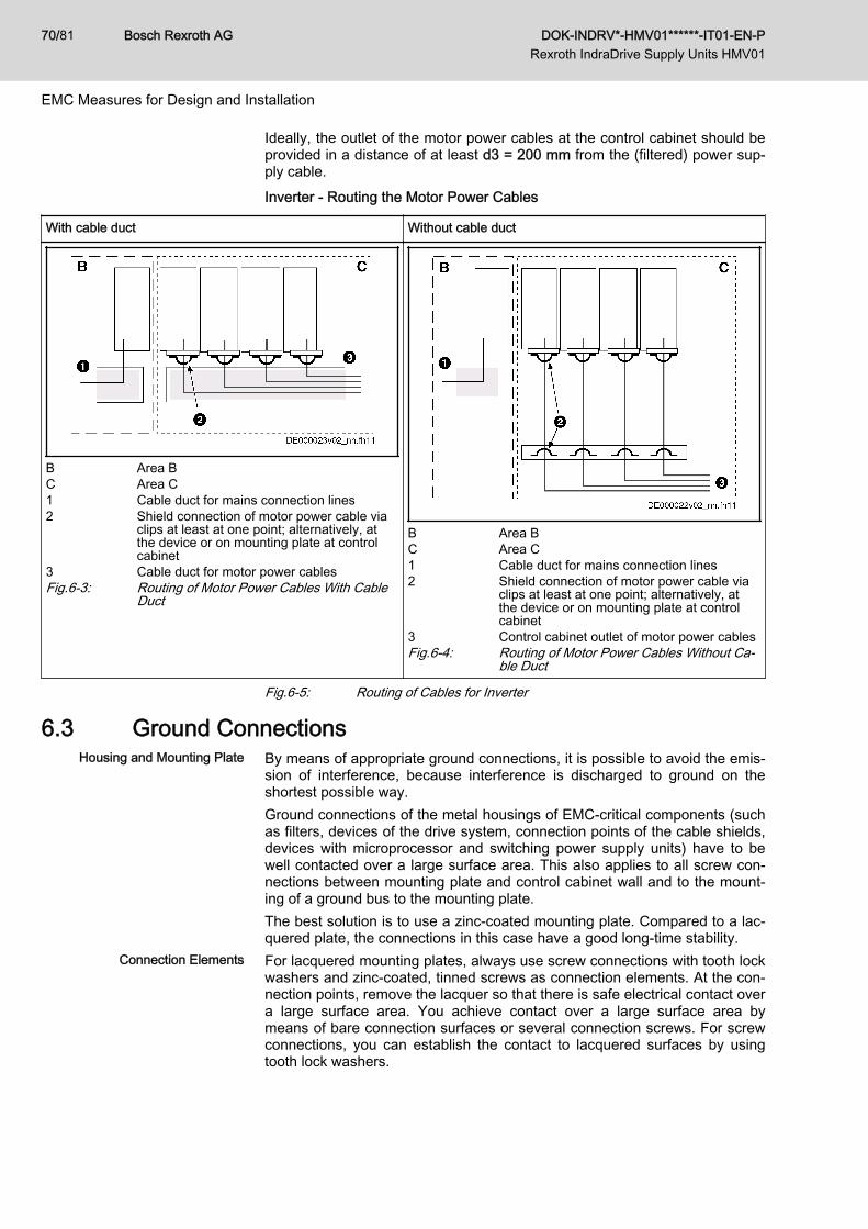
Ideally, the outlet of the motor power cables at the control cabinet should beprovided in a distance of at least d3 = 200 mm from the (filtered) power sup‐ply cable.Inverter - Routing the Motor Power Cables
With cable duct Without cable duct
B Area BC Area C1 Cable duct for mains connection lines2 Shield connection of motor power cable via
clips at least at one point; alternatively, atthe device or on mounting plate at controlcabinet
3 Cable duct for motor power cablesFig.6-3: Routing of Motor Power Cables With Cable
Duct
B Area BC Area C1 Cable duct for mains connection lines2 Shield connection of motor power cable via
clips at least at one point; alternatively, atthe device or on mounting plate at controlcabinet
3 Control cabinet outlet of motor power cablesFig.6-4: Routing of Motor Power Cables Without Ca‐
ble Duct
Fig.6-5: Routing of Cables for Inverter
6.3 Ground ConnectionsHousing and Mounting Plate By means of appropriate ground connections, it is possible to avoid the emis‐
sion of interference, because interference is discharged to ground on theshortest possible way.Ground connections of the metal housings of EMC-critical components (suchas filters, devices of the drive system, connection points of the cable shields,devices with microprocessor and switching power supply units) have to bewell contacted over a large surface area. This also applies to all screw con‐nections between mounting plate and control cabinet wall and to the mount‐ing of a ground bus to the mounting plate.The best solution is to use a zinc-coated mounting plate. Compared to a lac‐quered plate, the connections in this case have a good long-time stability.
Connection Elements For lacquered mounting plates, always use screw connections with tooth lockwashers and zinc-coated, tinned screws as connection elements. At the con‐nection points, remove the lacquer so that there is safe electrical contact overa large surface area. You achieve contact over a large surface area bymeans of bare connection surfaces or several connection screws. For screwconnections, you can establish the contact to lacquered surfaces by usingtooth lock washers.
Bosch Rexroth AG DOK-INDRV*-HMV01******-IT01-EN-P Rexroth IndraDrive Supply Units HMV01
70/81
EMC Measures for Design and Installation
Metal Surfaces Always use connection elements (screws, nuts, plain washers) with goodelectroconductive surface.Bare zinc-coated or tinned metal surfaces have good electroconductive prop‐erties.Anodized, yellow chromatized, black gunmetal finish or lacquered metal sur‐faces have bad electroconductive properties.
Ground Wires and Shield Connec‐tions
For connecting ground wires and shield connections, it is not the cross sec‐tion but the size of contact surface that is important, as the high-frequency in‐terference currents mainly flow on the surface of the conductor.Always connect cable shields, especially shields of the motor power cables,to ground potential over a large surface area.
6.4 Installing Signal Lines and Signal CablesLine Routing For measures to prevent interference, see the Project Planning Manuals of
the respective device. In addition, we recommend the following measures:● Route signal and control lines separately from the power cables with a
minimum distance of d5 = 100 mm (see 6.2.2 Division Into Areas(Zones), page 62) or with a grounded separating sheet. The optimumway is to route them in separate cable ducts. If possible, lead signallines into the control cabinet at one point only.
● If signal lines are crossing power cables, route them in an angle of 90°in order to avoid interference injection.
● Ground spare cables, that are not used and have been connected, atleast at both ends so that they do not have any antenna effect.
● Avoid unnecessary line lengths.● Run cables as close as possible to grounded metal surfaces (reference
potential). The ideal solution are closed, grounded cable ducts or metalpipes which, however, is only obligatory for high requirements (sensitiveinstrument leads).
● Avoid suspended lines or lines routed along synthetic carriers, becausethey are functioning like reception antennas (noise immunity) and liketransmitting antennas (emission of interference). Exceptional cases areflexible cable tracks over short distances of a maximum of 5 m.
Shielding Connect the cable shield immediately at the devices in the shortest and mostdirect possible way and over the largest possible surface area.Connect the shield of analog signal lines at one end over a large surfacearea, normally in the control cabinet at the analog device. Make sure the con‐nection to ground/housing is short and over a large surface area.Connect the shield of digital signal lines at both ends over a large surfacearea and in short form. In the case of potential differences between beginningand end of the line, run an additional bonding conductor in parallel. This pre‐vents compensating current from flowing via the shield. The guide value forthe cross section is 10 mm2.You absolutely have to equip separable connections with connectors withgrounded metal housing.In the case of non-shielded lines belonging to the same circuit, twist feederand return cable.
DOK-INDRV*-HMV01******-IT01-EN-P Rexroth IndraDrive Supply Units HMV01
Bosch Rexroth AG 71/81
EMC Measures for Design and Installation
6.5 General Measures of Radio Interference Suppression for Re‐lays, Contactors, Switches, Chokes and Inductive Loads
If, in conjunction with electronic devices and components, inductive loads,such as chokes, contactors, relays are switched by contacts or semiconduc‐tors, appropriate interference suppression has to be provided for them:● By arranging free-wheeling diodes in the case of d.c. operation● In the case of a.c. operation, by arranging usual RC interference sup‐
pression elements depending on the contactor type, immediately at theinductance
Only the interference suppression element arranged immediately at the in‐ductance does serve this purpose. Otherwise, the emitted noise level is toohigh which can affect the function of the electronic system and of the drive.
Bosch Rexroth AG DOK-INDRV*-HMV01******-IT01-EN-P Rexroth IndraDrive Supply Units HMV01
72/81
EMC Measures for Design and Installation
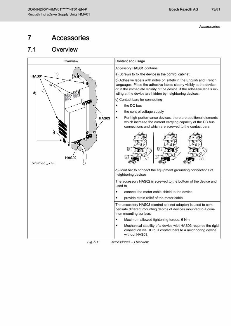
7 Accessories7.1 Overview
Overview Content and usage
Accessory HAS01 contains:a) Screws to fix the device in the control cabinetb) Adhesive labels with notes on safety in the English and Frenchlanguages. Place the adhesive labels clearly visibly at the deviceor in the immediate vicinity of the device, if the adhesive labels ex‐isting at the device are hidden by neighboring devices.c) Contact bars for connecting● the DC bus● the control voltage supply● For high-performance devices, there are additional elements
which increase the current carrying capacity of the DC busconnections and which are screwed to the contact bars:
d) Joint bar to connect the equipment grounding connections ofneighboring devices
The accessory HAS02 is screwed to the bottom of the device andused to● connect the motor cable shield to the device● provide strain relief of the motor cable
The accessory HAS03 (control cabinet adapter) is used to com‐pensate different mounting depths of devices mounted to a com‐mon mounting surface.● Maximum allowed tightening torque: 6 Nm● Mechanical stability of a device with HAS03 requires the rigid
connection via DC bus contact bars to a neighboring devicewithout HAS03.
Fig.7-1: Accessories – Overview
DOK-INDRV*-HMV01******-IT01-EN-P Rexroth IndraDrive Supply Units HMV01
Bosch Rexroth AG 73/81
Accessories

Bosch Rexroth AG DOK-INDRV*-HMV01******-IT01-EN-P Rexroth IndraDrive Supply Units HMV01
74/81
8 Service and SupportOur worldwide service network provides an optimized and efficient support.Our experts offer you advice and assistance should you have any queries.You can contact us 24/7.
Service Germany Our technology-oriented Competence Center in Lohr, Germany, is responsi‐ble for all your service-related queries for electric drive and controls.Contact the Service Helpdesk & Hotline under:
Phone: +49 9352 40 5060Fax: +49 9352 18 4941E-mail: [email protected]: http://www.boschrexroth.com
Additional information on service, repair (e.g. delivery addresses) and trainingcan be found on our internet sites.
Service worldwide Outside Germany, please contact your local service office first. For hotlinenumbers, refer to the sales office addresses on the internet.
Preparing information To be able to help you more quickly and efficiently, please have the followinginformation ready:● Detailed description of malfunction and circumstances resulting in the
malfunction● Type plate name of the affected products, in particular type codes and
serial numbers● Your contact data (phone and fax number as well as your email ad‐
dress)
DOK-INDRV*-HMV01******-IT01-EN-P Rexroth IndraDrive Supply Units HMV01
Bosch Rexroth AG 75/81
Service and Support

Bosch Rexroth AG DOK-INDRV*-HMV01******-IT01-EN-P Rexroth IndraDrive Supply Units HMV01
76/81
9 Environmental Protection and Disposal9.1 Environmental Protection
Production Processes The products are made with energy- and resource-optimized production pro‐cesses which allow re-using and recycling the resulting waste. We regularlytry to replace pollutant-loaded raw materials and supplies by more environ‐ment-friendly alternatives.
No Release of Hazardous Sub‐stances
Our products do not contain any hazardous substances which may be re‐leased in the case of appropriate use. Normally, our products will not haveany negativ influences on the environment.
Significant Components Basically, our products contain the following components:Electronic devices Motors∙ steel ∙ steel∙ aluminum ∙ aluminum∙ copper ∙ copper∙ synthetic materials ∙ brass∙ electronic components and modules ∙ magnetic materials ∙ electronic components and modules
9.2 DisposalReturn of Products Our products can be returned to our premises free of charge for disposal. It is
a precondition, however, that the products are free of oil, grease or other dirt.Furthermore, the products returned for disposal must not contain any undueforeign material or foreign components.Send the products ”free domicile” to the following address: Bosch Rexroth AG Electric Drives and Controls Buergermeister-Dr.-Nebel-Strasse 2 97816 Lohr am Main, Germany
Packaging The packaging materials consist of cardboard, wood and polystyrene. Thesematerials can be recycled anywhere without any problem.For ecological reasons, please refrain from returning the empty packages tous.
Batteries and Accumulators Batteries and accumulators can be labeled with this symbol.
The symbol indicating "separate collection" for all batteries and accu‐mulators is the crossed-out wheeled bin.The end user within the EU is legally obligated to return used batteries. Out‐side the validity of the EU Directive 2006/66/EC keep the stipulated direc‐tives.Used batteries can contain hazardous substances, which can harm the envi‐ronment or the people´s health when they are improper stored or disposed of.After use, the batteries or accumulators contained in Rexroth products haveto be properly disposed of according to the country-specific collection.
Recycling Most of the products can be recycled due to their high content of metal. Inorder to recycle the metal in the best possible way, the products must be dis‐assembled into individual modules.
DOK-INDRV*-HMV01******-IT01-EN-P Rexroth IndraDrive Supply Units HMV01
Bosch Rexroth AG 77/81
Environmental Protection and Disposal

Metals contained in electric and electronic modules can also be recycled bymeans of special separation processes.Products made of plastics can contain flame retardants. These plastic partsare labeled according to EN ISO 1043. They have to be recycled separatelyor disposed of according to the valid legal requirements.
Bosch Rexroth AG DOK-INDRV*-HMV01******-IT01-EN-P Rexroth IndraDrive Supply Units HMV01
78/81
Environmental Protection and Disposal
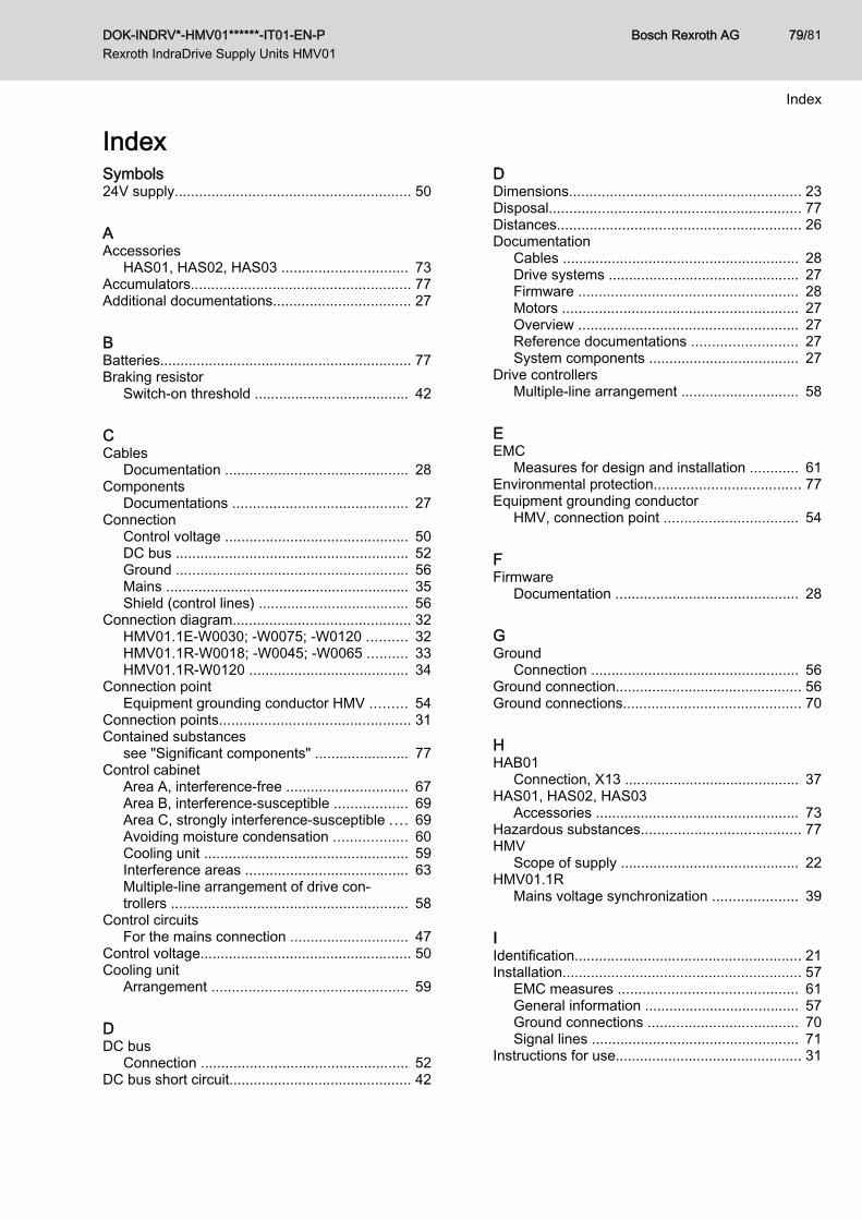
IndexSymbols24V supply.......................................................... 50
AAccessories
HAS01, HAS02, HAS03 ............................... 73Accumulators...................................................... 77Additional documentations.................................. 27
BBatteries.............................................................. 77Braking resistor
Switch-on threshold ...................................... 42
CCables
Documentation ............................................. 28Components
Documentations ........................................... 27Connection
Control voltage ............................................. 50DC bus ......................................................... 52Ground ......................................................... 56Mains ............................................................ 35Shield (control lines) ..................................... 56
Connection diagram............................................ 32HMV01.1E-W0030; -W0075; -W0120 .......... 32HMV01.1R-W0018; -W0045; -W0065 .......... 33HMV01.1R-W0120 ....................................... 34
Connection pointEquipment grounding conductor HMV ......... 54
Connection points............................................... 31Contained substances
see "Significant components" ....................... 77Control cabinet
Area A, interference-free .............................. 67Area B, interference-susceptible .................. 69Area C, strongly interference-susceptible .... 69Avoiding moisture condensation .................. 60Cooling unit .................................................. 59Interference areas ........................................ 63Multiple-line arrangement of drive con‐trollers .......................................................... 58
Control circuitsFor the mains connection ............................. 47
Control voltage.................................................... 50Cooling unit
Arrangement ................................................ 59
DDC bus
Connection ................................................... 52DC bus short circuit............................................. 42
DDimensions......................................................... 23Disposal.............................................................. 77Distances............................................................ 26Documentation
Cables .......................................................... 28Drive systems ............................................... 27Firmware ...................................................... 28Motors .......................................................... 27Overview ...................................................... 27Reference documentations .......................... 27System components ..................................... 27
Drive controllersMultiple-line arrangement ............................. 58
EEMC
Measures for design and installation ............ 61Environmental protection.................................... 77Equipment grounding conductor
HMV, connection point ................................. 54
FFirmware
Documentation ............................................. 28
GGround
Connection ................................................... 56Ground connection.............................................. 56Ground connections............................................ 70
HHAB01
Connection, X13 ........................................... 37HAS01, HAS02, HAS03
Accessories .................................................. 73Hazardous substances....................................... 77HMV
Scope of supply ............................................ 22HMV01.1R
Mains voltage synchronization ..................... 39
IIdentification........................................................ 21Installation........................................................... 57
EMC measures ............................................ 61General information ...................................... 57Ground connections ..................................... 70Signal lines ................................................... 71
Instructions for use.............................................. 31
DOK-INDRV*-HMV01******-IT01-EN-P Rexroth IndraDrive Supply Units HMV01
Bosch Rexroth AG 79/81
Index
LL+, L-
DC bus ......................................................... 52
MMains connection................................................ 35
Control circuits ............................................. 47Mains contactor
External ........................................................ 47Mains contactor control....................................... 42Mains contactor external
Acknowledge messages .............................. 49Mains contactor internal
Acknowledge messages .............................. 45Mains filter
Motor fan ...................................................... 68Other loads ................................................... 68
Mains voltage synchronization............................ 38HMV01.1R .................................................... 39
Measures of radio interference suppressionFor relays, contactors, switches, chokes,inductive loads ............................................. 72
Messages Bb1, UD, WARNX31 ............................................................... 40
Moisture condensationAvoiding ....................................................... 60
MotorDocumentation ............................................. 27
Motor fanMains filter .................................................... 68
Multiple-line arrangement of drive controllers..... 58
PPackaging........................................................... 77Power consumption............................................ 23Production processes......................................... 77Project planning manuals.................................... 27
RRatings................................................................ 23Recycling............................................................ 77Reference documentations................................. 27Return of products.............................................. 77
SSafety instructions............................................... 13Scope of supply
HMV ............................................................. 22Shield
Connection (control lines) ............................ 56
SShield connection................................................ 56Signal lines
Installation .................................................... 71Significant components....................................... 77Supply HAB01
X13 ............................................................... 37Support
See service hotline ....................................... 75
TType code........................................................... 21Type plates......................................................... 22
UUse
Instructions ................................................... 31
VVoltage load capacity.......................................... 23
WWiring diagram.................................................... 31
XX13
Supply fan unit HAB01 ................................. 37X14
Mains voltage synchronization ..................... 38X3
Mains connection ......................................... 35X31
Messages Bb1, UD, WARN ........................ 40X32
Mains contactor control and DC bus shortcircuit ............................................................ 42
X33Acknowledge messages of integratedmains contactor ............................................ 45
X34Contact for controlling the external mainscontactor ...................................................... 47
X40Acknowledge messages of externalmains contactor ............................................ 49
XS1..................................................................... 56
Bosch Rexroth AG DOK-INDRV*-HMV01******-IT01-EN-P Rexroth IndraDrive Supply Units HMV01
80/81
Index

Notes
DOK-INDRV*-HMV01******-IT01-EN-P Rexroth IndraDrive Supply Units HMV01
Bosch Rexroth AG 81/81
DOK-INDRV*-HMV01******-IT01-EN-P
Bosch Rexroth AG Electric Drives and Controls P.O. Box 13 57 97803 Lohr, Germany Bgm.-Dr.-Nebel-Str. 2 97816 Lohr, Germany Tel. +49 9352 18 0 Fax +49 9352 18 8400 www.boschrexroth.com/electrics
R911339050