
Rexroth IndraDrive Drive Controllers Edition 02 Control ... Rexroth/Drives/Indradrive... ·...
134
R911295012 Edition 02 Rexroth IndraDrive Drive Controllers Control Sections Project Planning Manual Industrial Hydraulics Electric Drives and Controls Linear Motion and Assembly Technologies Pneumatics Service Automation Mobile Hydraulics
Transcript of Rexroth IndraDrive Drive Controllers Edition 02 Control ... Rexroth/Drives/Indradrive... ·...

R911295012Edition 02
Rexroth IndraDriveDrive ControllersControl Sections
Project Planning Manual
IndustrialHydraulics
Electric Drivesand Controls
Linear Motion andAssembly Technologies Pneumatics
ServiceAutomation
MobileHydraulics

About this Documentation Rexroth IndraDrive
DOK-INDRV*-CSH********-PR02-EN-P
Rexroth IndraDrive
Drive Controllers
Control Sections
Project Planning Manual
DOK-INDRV*-CSH********-PR02-EN-P
Document number 120-2400-B302-02/EN
Description ReleaseDate
Notes
DOK-INDRV*-CHS********-PR01-EN-P 11.2003 first edition
DOK-INDRV*-CHS********-PR02-EN-P 04.2004 revision
Bosch Rexroth AG 2003
Copying this document, giving it to others and the use or communicationof the contents thereof without express authority, are forbidden. Offendersare liable for the payment of damages. All rights are reserved in the eventof the grant of a patent or the registration of a utility model or design(DIN 34-1).
The specified data only serve to describe the product. No statementsconcerning a certain condition or suitability for a certain application can bederived from our information. The given information does not release theuser from the obligation of own judgement and verification. It must beremembered that our products are subject to a natural process of wearand aging.
Bosch Rexroth AGBgm.-Dr.-Nebel-Str. 2 • D-97816 Lohr a. Main
Telephone +49 (0)93 52/40-0 • Tx 68 94 21 • Fax +49 (0)93 52/40-48 85
http://www.boschrexroth.de/
Dept. EDY1 (US)
This document has been printed on chlorine-free bleached paper.
Title
Type of Documentation
Document Typecode
Internal File Reference
Record of Revisions
Copyright
Validity
Published by
Note

Rexroth IndraDrive I
DOK-INDRV*-CSH********-PR02-EN-P
Contents
1 Introduction 1-1
1.1 Documentation .............................................................................................................................. 1-1
Purpose of this Documentation................................................................................................ 1-1
Documentations - Overview..................................................................................................... 1-1
1.2 Basic Structure of the Drive Controller Rexroth IndraDrive .......................................................... 1-2
1.3 Power Section ............................................................................................................................... 1-3
1.4 Control Section.............................................................................................................................. 1-3
2 Important Directions for Use 2-1
2.1 Appropriate Use ............................................................................................................................ 2-1
Introduction .............................................................................................................................. 2-1
Areas of Use and Application................................................................................................... 2-2
2.2 Inappropriate Use.......................................................................................................................... 2-2
3 Safety Instructions for Electric Drives and Controls 3-1
3.1 Introduction ................................................................................................................................... 3-1
3.2 Explanations.................................................................................................................................. 3-1
3.3 Hazards by Improper Use ............................................................................................................. 3-2
3.4 General Information ...................................................................................................................... 3-3
3.5 Protection Against Contact with Electrical Parts........................................................................... 3-5
3.6 Protection Against Electric Shock by Protective Low Voltage (PELV) ......................................... 3-6
3.7 Protection Against Dangerous Movements .................................................................................. 3-7
3.8 Protection Against Magnetic and Electromagnetic Fields During Operation andMounting ....................................................................................................................................... 3-9
3.9 Protection Against Contact with Hot Parts .................................................................................. 3-10
3.10 Protection During Handling and Mounting .................................................................................. 3-10
3.11 Battery Safety.............................................................................................................................. 3-11
3.12 Protection Against Pressurized Systems.................................................................................... 3-11
4 Identification of the Control Section 4-1
4.1 Type Plates ................................................................................................................................... 4-1
Control Section Type Plate ...................................................................................................... 4-1
4.2 Type Codes................................................................................................................................... 4-2
BASIC ...................................................................................................................................... 4-2
ADVANCED ............................................................................................................................. 4-6
5 Transport and Storage 5-1
5.1 Transporting the Devices .............................................................................................................. 5-1
Conditions ................................................................................................................................ 5-1

II Contents Rexroth IndraDrive
DOK-INDRV*-CSH********-PR02-EN-P
5.2 Storing the Devices ....................................................................................................................... 5-1
Conditions ................................................................................................................................ 5-1
In Case of Long Storage Periods............................................................................................. 5-1
6 Fixed Interfaces 6-1
6.1 Overview ....................................................................................................................................... 6-2
BASIC OPENLOOP ................................................................................................................. 6-2
BASIC SERCOS ...................................................................................................................... 6-3
BASIC PROFIBUS................................................................................................................... 6-4
BASIC ANALOG ...................................................................................................................... 6-5
BASIC UNIVERSAL................................................................................................................. 6-6
ADVANCED ............................................................................................................................. 6-7
6.2 X2, Serial Interface (RS232) ......................................................................................................... 6-8
6.3 X7, MultiMediaCard..................................................................................................................... 6-10
6.4 X8, ENS (Encoder Interface) ...................................................................................................... 6-11
6.5 X11/X12, Relay Contacts............................................................................................................ 6-16
6.6 X16, Encoder Emulation ............................................................................................................. 6-18
6.7 X31/X32, Digital and Analog Inputs/Outputs, Relay Contacts, Voltage Input (24V, 0V) ............ 6-24
Relay Rel1.............................................................................................................................. 6-27
Digital Inputs E1 ... E3 ........................................................................................................... 6-28
Digital Inputs E4 ... E7 ........................................................................................................... 6-29
Digital Inputs E/A8 ... E/A11................................................................................................... 6-30
Digital Outputs E/A8 ... E/A11................................................................................................ 6-31
Analog Inputs EAn+ and EAn- ............................................................................................... 6-32
Analog Inputs EAn1+, EAn1-, EAn2+ and EAn2- .................................................................. 6-33
Analog Outputs An1, An2 ...................................................................................................... 6-34
Voltage Input (+24V, 0V) ....................................................................................................... 6-37
6.8 X33/X34, Digital Inputs................................................................................................................ 6-38
6.9 X35/X36, Analog Inputs/Outputs; Voltage Output (24V, 0V) ...................................................... 6-39
Analog Inputs ......................................................................................................................... 6-40
Analog Outputs ...................................................................................................................... 6-40
Voltage Output (+24V, 0V)..................................................................................................... 6-40
6.10 X*, Master Communication ......................................................................................................... 6-41
SERCOS interface (X20, X21)............................................................................................... 6-41
PROFIBUS Interface (X30).................................................................................................... 6-44
Parallel Interface (X15) .......................................................................................................... 6-48
6.11 H1 (Control Panel) ...................................................................................................................... 6-51
7 Options 7-1
7.1 Overview ....................................................................................................................................... 7-1
BASIC SERCOS ...................................................................................................................... 7-1
BASIC PROFIBUS................................................................................................................... 7-2
BASIC ANALOG ...................................................................................................................... 7-3
BASIC UNIVERSAL................................................................................................................. 7-4
ADVANCED ............................................................................................................................. 7-5
Reference to Description of Options........................................................................................ 7-6

Rexroth IndraDrive Contents III
DOK-INDRV*-CSH********-PR02-EN-P
7.2 Encoder......................................................................................................................................... 7-7
EN1: HSF, Resolver................................................................................................................. 7-7
EN2: EnDat2.1, 1Vss, 5VTTL ................................................................................................ 7-11
ENS: 1Vpp; HIPERFACE®, IndraDyn ................................................................................... 7-18
MEM: Encoder Emulator Module........................................................................................... 7-19
7.3 Integrated Safety Technology ..................................................................................................... 7-20
L1: Starting Lockout ............................................................................................................... 7-20
S1: Safety Technology I/O ..................................................................................................... 7-22
7.4 MD1: Digital Input/Output Extension........................................................................................... 7-24
7.5 MA1: Analog Input/Output Extension.......................................................................................... 7-27
8 Service & Support 8-1
8.1 Helpdesk ....................................................................................................................................... 8-1
8.2 Service-Hotline.............................................................................................................................. 8-1
8.3 Internet .......................................................................................................................................... 8-1
8.4 Vor der Kontaktaufnahme... - Before contacting us...................................................................... 8-1
8.5 Kundenbetreuungsstellen - Sales & Service Facilities ................................................................. 8-2
9 Appendix 9-1
9.1 Power Consumption of Control Sections ...................................................................................... 9-1
9.2 Commissioning Aids Required in Preparation for Commissioning ............................................... 9-1
10 Index 10-1

IV Contents Rexroth IndraDrive
DOK-INDRV*-CSH********-PR02-EN-P

Rexroth IndraDrive Introduction 1-1
DOK-INDRV*-CSH********-PR02-EN-P
1 Introduction
1.1 Documentation
Purpose of this DocumentationThis documentation describes
• the planning the electrical construction
• the installation of the drive system
Documentations - Overview
Title Type of Documentation Document Typecode1)
Rexroth IndraDriveDrive ControllersControl Sections
Project Planning Manual DOK-INDRV*-CSH********-PRxx-EN-P
Rexroth IndraDrive MDrive ControllersPower Sections
Project Planning Manual DOK-INDRV*-HMS+HMD****-PRxx-EN-P
Rexroth IndraDrive CDrive ControllersPower Sections HCS02.1
Project Planning Manual DOK-INDRV*-HCS02.1****-PRxx-EN-P
Rexroth IndraDrive CDrive ControllersPower Sections HCS03.1
Project Planning Manual DOK-INDRV*-HCS03.1****-PRxx-EN-P
Rexroth IndraDriveSupply Units
Project Planning Manual DOK-INDRV*-HMV-*******-PRxx-EN-P
Electromagnetic Compatibility (EMC) inDrive and Control Systems
Project Planning Manual DOK-GENERAL-EMV********-PRxx-EN-P
Rexroth IndraDriveIntegrated Safety Technology
Functional and ApplicationDescription
DOK-INDRV*-SI*-**VRS**-FKxx-EN-P
Connecting cables Selection Data DOK-CONNEC-CABLE*STAND-AUxx-EN-P
Safety Instructions for Electrical Drives Safety Guidelines DOK-GENERAL-DRIVE-******-SVSx-MS-P
1) in the document type codes "xx" designates replacement charactersfor the update edition of the documentation (Example: "PR01" is thefirst edition of a project planning manual)
Fig. 1-1: Documentations - Overview

1-2 Introduction Rexroth IndraDrive
DOK-INDRV*-CSH********-PR02-EN-P
1.2 Basic Structure of the Drive Controller Rexroth IndraDrive
����������
�
1: Power section2: Control section
Fig. 1-2: Basic structure of the drive controller Rexroth IndraDrive
The drive controller consists of two essential parts:
• Power section
• Control section

Rexroth IndraDrive Introduction 1-3
DOK-INDRV*-CSH********-PR02-EN-P
1.3 Power Section
Detailed informations: See Project Planning Manuals of RexrothIndraDrive Power Sections (see page 1-1).
1.4 Control Section
The control section is a separate section which is inserted into the powersection. The drive controller is supplied ex works complete with controlsection.
Note: The control section must only be replaced by a Rexrothservice engineer or by a trained user. Optional modules of thecontrol section must only be replaced by a Rexroth serviceengineer.
There are following control sections:
• BASIC OPENLOOP (single-axis; type code: CSB01.1N-FC-...)
• BASIC SERCOS (single-axis; type code: CSB01.1N-SE-...)
• BASIC PROFIBUS (single-axis; type code: CSB01.1N-PB-...)
• BASIC ANALOG (single-axis; type code: CSB01.1N-AN-...)
• BASIC UNIVERSAL (single-axis; type code: CSB01.1C-...;double-axis; type code: CDB01.1C-...)
• ADVANCED (type code: CSH01.1C-...)
Note: Complete type codes: see chapter 4
The control sections differ regarding their configurability, interfaces, cycletime, and pulse frequency. The following table shows an overview:

1-4 Introduction Rexroth IndraDrive
DOK-INDRV*-CSH********-PR02-EN-P
BA
SIC
OP
EN
LO
OP
(CS
B01
.1N
-FC
)
BA
SIC
S
ER
CO
S(C
SB
01.1
N-S
E)
BA
SIC
P
RO
FIB
US
(CS
B01
.1N
-PB
)
BA
SIC
AN
AL
OG
(CS
B01
.1N
-AN
)
BA
SIC
UN
IVE
RS
AL
(CS
B01
.1C
; S
ing
le-a
xis)
BA
SIC
UN
IVE
RS
AL
(CD
B01
.1C
; D
ou
ble
-axi
s)
AD
VA
NC
ED
(CS
H01
.1C
)
Configurable no no no no yes yes yes
Optional Modules:
Option 1 encoder[ENS] 3)
encoder[ENS]
encoder[ENS]
encoder[ENS]
o 1) o
Option 2 o o o
Option 3 o o
Option 4 o
Option Safety Technology I/O o 4) o 4) o 4) o 4) o o
Master Communication:
SERCOS x 1) o o o
PROFIBUS x o o o
Parallel o o o
Analog x o 5)
Standard Frequency Converter x
Serial Interface RS232 x x x x x x x
Inputs/Outputs:
Digital Inputs 8x 2) 5x 5x 5x 5x 14x 7x
thereof probe 1x 1x 1x 2x 2x
Digital Inputs/Outputs 3x 3x 4x 3x 8x 4x
Analog Inputs 2x 2x 1x 1x
Analog Outputs 2x 2x 2x
Relay Outputs 3x 1x 1x 1x 1x 1x 1x
Encoder systems:
IndraDyn, HIPERFACE®, 1Vss [ENS] 3) x x x x o o
HSF/RSF [EN1] o o o
EnDat2.1 / 1Vss / 5V TTL [EN2] o o o
Encoder Emulator [MEM] x o o o
Further Options:
Drive Interlock [L1] o o o o o o
Safety Technology I/O [S1] o o
Digital I/O Extension [MD1] o
Analog I/O Extension [MA1] o o o
MultiMediaCard o o o

Rexroth IndraDrive Introduction 1-5
DOK-INDRV*-CSH********-PR02-EN-P
BA
SIC
OP
EN
LO
OP
(CS
B01
.1N
-FC
)
BA
SIC
S
ER
CO
S(C
SB
01.1
N-S
E)
BA
SIC
P
RO
FIB
US
(CS
B01
.1N
-PB
)
BA
SIC
AN
AL
OG
(CS
B01
.1N
-AN
)
BA
SIC
UN
IVE
RS
AL
(CS
B01
.1C
; S
ing
le-a
xis)
BA
SIC
UN
IVE
RS
AL
(CD
B01
.1C
; D
ou
ble
-axi
s)
AD
VA
NC
ED
(CS
H01
.1C
)
Cycle time:
Current control 125 µs 125 µs 125 µs 125 µs 125 µs 125 µs 62,5 µs
Velocity control 250 µs 250 µs 250 µs 250 µs 250 µs 250 µs 125 µs
Position control 500 µs 500 µs 500 µs 500 µs 500 µs 500 µs 250 µs
Minimal SERCOS cycle time 500 µs 500 µs 500 µs 500 µs 500 µs 500 µs 250 µs
Pulse frequency:
4 kHz o o o o o o o
8 kHz o o o o o o o
12 kHz o
16 kHz o
1) x = standard; o = option2) the number before the x means die number of inputs/outputs present3) designation of options in brackets4) starting lockout only5) requires MEM option
Fig. 1-3: Overview of control sections
1-6 Introduction Rexroth IndraDrive
DOK-INDRV*-CSH********-PR02-EN-P
Notes

Rexroth IndraDrive Important Directions for Use 2-1
DOK-INDRV*-CSH********-PR02-EN-P
2 Important Directions for Use
2.1 Appropriate Use
IntroductionRexroth products represent state-of-the-art developments andmanufacturing. They are tested prior to delivery to ensure operating safetyand reliability.
The products may only be used in the manner that is defined asappropriate. If they are used in an inappropriate manner, then situationscan develop that may lead to property damage or injury to personnel.
Note: Rexroth, as manufacturer, is not liable for any damagesresulting from inappropriate use. In such cases, the guaranteeand the right to payment of damages resulting frominappropriate use are forfeited. The user alone carries allresponsibility of the risks.
Before using Rexroth products, make sure that all the pre-requisites foran appropriate use of the products are satisfied:
• Personnel that in any way, shape or form uses our products must firstread and understand the relevant safety instructions and be familiarwith appropriate use.
• If the product takes the form of hardware, then they must remain intheir original state, in other words, no structural changes are permitted.It is not permitted to decompile software products or alter sourcecodes.
• Do not mount damaged or faulty products or use them in operation.
• Make sure that the products have been installed in the mannerdescribed in the relevant documentation.

2-2 Important Directions for Use Rexroth IndraDrive
DOK-INDRV*-CSH********-PR02-EN-P
Areas of Use and ApplicationDrive controllers made by Rexroth are designed to control electricalmotors and monitor their operation.
Control and monitoring of the motors may require additional sensors andactors.
Note: The drive controllers may only be used with the accessoriesand parts specified in this document. If a component has notbeen specifically named, then it may not be either mounted orconnected. The same applies to cables and lines.
Operation is only permitted in the specified configurations andcombinations of components using the software and firmwareas specified in the relevant function descriptions.
Every drive controller has to be programmed before starting it up, makingit possible for the motor to execute the specific functions of an application.
The drive controllers are designed for use in single or multiple-axis driveand control applications.
To ensure an application-specific use, the drive controllers are availablewith differing drive power and different interfaces.
Typical applications of drive controllers are:
• handling and mounting systems,
• packaging and foodstuff machines,
• printing and paper processing machines and
• machine tools.
The drive controllers may only be operated under the assembly,installation and ambient conditions as described here (temperature,system of protection, humidity, EMC requirements, etc.) and in theposition specified.
2.2 Inappropriate Use
Using the drive controllers outside of the above-referenced areas ofapplication or under operating conditions other than described in thedocument and the technical data specified is defined as “inappropriateuse".
Drive controllers may not be used if
• they are subject to operating conditions that do not meet the abovespecified ambient conditions. This includes, for example, operationunder water, in the case of extreme temperature fluctuations orextremely high maximum temperatures or if
• Rexroth has not specifically released them for that intended purpose.Please note the specifications outlined in the general safetyinstructions!

Rexroth IndraDrive Safety Instructions for Electric Drives and Controls 3-1
DOK-INDRV*-CSH********-PR02-EN-P
3 Safety Instructions for Electric Drives and Controls
3.1 Introduction
Read these instructions before the initial startup of the equipment in orderto eliminate the risk of bodily harm or material damage. Follow thesesafety instructions at all times.
Do not attempt to install or start up this equipment without first reading alldocumentation provided with the product. Read and understand thesesafety instructions and all user documentation of the equipment prior toworking with the equipment at any time. If you do not have the userdocumentation for your equipment, contact your local Rexrothrepresentative to send this documentation immediately to the person orpersons responsible for the safe operation of this equipment.
If the equipment is resold, rented or transferred or passed on to others,then these safety instructions must be delivered with the equipment.
WARNING
Improper use of this equipment, failure to followthe safety instructions in this document ortampering with the product, including disablingof safety devices, may result in materialdamage, bodily harm, electric shock or evendeath!
3.2 Explanations
The safety instructions describe the following degrees of hazardseriousness in compliance with ANSI Z535. The degree of hazardseriousness informs about the consequences resulting from non-compliance with the safety instructions.
Warning symbol with signalword
Degree of hazard seriousness accordingto ANSI
DANGER
Death or severe bodily harm will occur.
WARNING
Death or severe bodily harm may occur.
CAUTION
Bodily harm or material damage may occur.
Fig. 3-1: Hazard classification (according to ANSI Z535)

3-2 Safety Instructions for Electric Drives and Controls Rexroth IndraDrive
DOK-INDRV*-CSH********-PR02-EN-P
3.3 Hazards by Improper Use
DANGER
High voltage and high discharge current!Danger to life or severe bodily harm by electricshock!
DANGER
Dangerous movements! Danger to life, severebodily harm or material damage byunintentional motor movements!
WARNING
High electrical voltage due to wrongconnections! Danger to life or bodily harm byelectric shock!
WARNING
Health hazard for persons with heartpacemakers, metal implants and hearing aids inproximity to electrical equipment!
CAUTION
Surface of machine housing could be extremelyhot! Danger of injury! Danger of burns!
CAUTION
Risk of injury due to improper handling! Bodilyharm caused by crushing, shearing, cutting andmechanical shock or incorrect handling ofpressurized systems!
CAUTION
Risk of injury due to incorrect handling ofbatteries!

Rexroth IndraDrive Safety Instructions for Electric Drives and Controls 3-3
DOK-INDRV*-CSH********-PR02-EN-P
3.4 General Information
• Bosch Rexroth AG is not liable for damages resulting from failure toobserve the warnings provided in this documentation.
• Read the operating, maintenance and safety instructions in yourlanguage before starting up the machine. If you find that you cannotcompletely understand the documentation for your product, please askyour supplier to clarify.
• Proper and correct transport, storage, assembly and installation aswell as care in operation and maintenance are prerequisites foroptimal and safe operation of this equipment.
• Only persons who are trained and qualified for the use and operationof the equipment may work on this equipment or within its proximity.
• The persons are qualified if they have sufficient knowledge of theassembly, installation and operation of the equipment as well as anunderstanding of all warnings and precautionary measures noted inthese instructions.
• Furthermore, they must be trained, instructed and qualified toswitch electrical circuits and equipment on and off in accordancewith technical safety regulations, to ground them and to mark themaccording to the requirements of safe work practices. They musthave adequate safety equipment and be trained in first aid.
• Only use spare parts and accessories approved by the manufacturer.
• Follow all safety regulations and requirements for the specificapplication as practiced in the country of use.
• The equipment is designed for installation in industrial machinery.
• The ambient conditions given in the product documentation must beobserved.
• Use only safety features and applications that are clearly and explicitlyapproved in the Project Planning Manual.For example, the following areas of use are not permitted: constructioncranes, elevators used for people or freight, devices and vehicles totransport people, medical applications, refinery plants, transport ofhazardous goods, nuclear applications, applications sensitive to highfrequency, mining, food processing, control of protection equipment(also in a machine).
• The information given in the documentation of the product with regardto the use of the delivered components contains only examples ofapplications and suggestions.The machine and installation manufacturer must
• make sure that the delivered components are suited for hisindividual application and check the information given in thisdocumentation with regard to the use of the components,
• make sure that his application complies with the applicable safetyregulations and standards and carry out the required measures,modifications and complements.
• Startup of the delivered components is only permitted once it is surethat the machine or installation in which they are installed complieswith the national regulations, safety specifications and standards of theapplication.

3-4 Safety Instructions for Electric Drives and Controls Rexroth IndraDrive
DOK-INDRV*-CSH********-PR02-EN-P
• Operation is only permitted if the national EMC regulations for theapplication are met.The instructions for installation in accordance with EMC requirementscan be found in the documentation "EMC in Drive and ControlSystems".The machine or installation manufacturer is responsible forcompliance with the limiting values as prescribed in the nationalregulations.
• Technical data, connections and operational conditions are specified inthe product documentation and must be followed at all times.

Rexroth IndraDrive Safety Instructions for Electric Drives and Controls 3-5
DOK-INDRV*-CSH********-PR02-EN-P
3.5 Protection Against Contact with Electrical Parts
Note: This section refers to equipment and drive components withvoltages above 50 Volts.
Touching live parts with voltages of 50 Volts and more with bare hands orconductive tools or touching ungrounded housings can be dangerous andcause electric shock. In order to operate electrical equipment, certainparts must unavoidably have dangerous voltages applied to them.
DANGER
High electrical voltage! Danger to life, severebodily harm by electric shock!⇒ Only those trained and qualified to work with or on
electrical equipment are permitted to operate, maintainor repair this equipment.
⇒ Follow general construction and safety regulations whenworking on high voltage installations.
⇒ Before switching on power the ground wire must bepermanently connected to all electrical units accordingto the connection diagram.
⇒ Do not operate electrical equipment at any time, evenfor brief measurements or tests, if the ground wire is notpermanently connected to the points of the componentsprovided for this purpose.
⇒ Before working with electrical parts with voltage higherthan 50 V, the equipment must be disconnected fromthe mains voltage or power supply. Make sure theequipment cannot be switched on again unintended.
⇒ The following should be observed with electrical driveand filter components:
⇒ Wait five (5) minutes after switching off power to allowcapacitors to discharge before beginning to work.Measure the voltage on the capacitors before beginningto work to make sure that the equipment is safe totouch.
⇒ Never touch the electrical connection points of acomponent while power is turned on.
⇒ Install the covers and guards provided with theequipment properly before switching the equipment on.Prevent contact with live parts at any time.
⇒ A residual-current-operated protective device (RCD)must not be used on electric drives! Indirect contactmust be prevented by other means, for example, by anovercurrent protective device.
⇒ Electrical components with exposed live parts anduncovered high voltage terminals must be installed in aprotective housing, for example, in a control cabinet.

3-6 Safety Instructions for Electric Drives and Controls Rexroth IndraDrive
DOK-INDRV*-CSH********-PR02-EN-P
To be observed with electrical drive and filter components:
DANGER
High electrical voltage on the housing!High leakage current! Danger to life, danger ofinjury by electric shock!⇒ Connect the electrical equipment, the housings of all
electrical units and motors permanently with the safetyconductor at the ground points before power isswitched on. Look at the connection diagram. This iseven necessary for brief tests.
⇒ Connect the safety conductor of the electricalequipment always permanently and firmly to thesupply mains. Leakage current exceeds 3.5 mA innormal operation.
⇒ Use a copper conductor with at least 10 mm² crosssection over its entire course for this safety conductorconnection!
⇒ Prior to startups, even for brief tests, always connectthe protective conductor or connect with ground wire.Otherwise, high voltages can occur on the housingthat lead to electric shock.
3.6 Protection Against Electric Shock by Protective LowVoltage (PELV)
All connections and terminals with voltages between 0 and 50 Volts onRexroth products are protective low voltages designed in accordance withinternational standards on electrical safety.
WARNING
High electrical voltage due to wrongconnections! Danger to life, bodily harm byelectric shock!⇒ Only connect equipment, electrical components and
cables of the protective low voltage type (PELV =Protective Extra Low Voltage) to all terminals andclamps with voltages of 0 to 50 Volts.
⇒ Only electrical circuits may be connected which aresafely isolated against high voltage circuits. Safeisolation is achieved, for example, with an isolatingtransformer, an opto-electronic coupler or whenbattery-operated.

Rexroth IndraDrive Safety Instructions for Electric Drives and Controls 3-7
DOK-INDRV*-CSH********-PR02-EN-P
3.7 Protection Against Dangerous Movements
Dangerous movements can be caused by faulty control of the connectedmotors. Some common examples are:
• improper or wrong wiring of cable connections
• incorrect operation of the equipment components
• wrong input of parameters before operation
• malfunction of sensors, encoders and monitoring devices
• defective components
• software or firmware errors
Dangerous movements can occur immediately after equipment isswitched on or even after an unspecified time of trouble-free operation.
The monitoring in the drive components will normally be sufficient to avoidfaulty operation in the connected drives. Regarding personal safety,especially the danger of bodily injury and material damage, this alonecannot be relied upon to ensure complete safety. Until the integratedmonitoring functions become effective, it must be assumed in any casethat faulty drive movements will occur. The extent of faulty drivemovements depends upon the type of control and the state of operation.

3-8 Safety Instructions for Electric Drives and Controls Rexroth IndraDrive
DOK-INDRV*-CSH********-PR02-EN-P
DANGER
Dangerous movements! Danger to life, risk ofinjury, severe bodily harm or material damage!⇒ Ensure personal safety by means of qualified and
tested higher-level monitoring devices or measuresintegrated in the installation. Unintended machinemotion is possible if monitoring devices are disabled,bypassed or not activated.
⇒ Pay attention to unintended machine motion or othermalfunction in any mode of operation.
⇒ Keep free and clear of the machine’s range of motionand moving parts. Possible measures to preventpeople from accidentally entering the machine’s rangeof motion:
- use safety fences
- use safety guards
- use protective coverings
- install light curtains or light barriers
⇒ Fences and coverings must be strong enough toresist maximum possible momentum, especially ifthere is a possibility of loose parts flying off.
⇒ Mount the emergency stop switch in the immediatereach of the operator. Verify that the emergency stopworks before startup. Don’t operate the machine if theemergency stop is not working.
⇒ Isolate the drive power connection by means of anemergency stop circuit or use a starting lockout toprevent unintentional start.
⇒ Make sure that the drives are brought to a safestandstill before accessing or entering the dangerzone. Safe standstill can be achieved by switching offthe power supply contactor or by safe mechanicallocking of moving parts.
⇒ Secure vertical axes against falling or dropping afterswitching off the motor power by, for example:
- mechanically securing the vertical axes
- adding an external braking/ arrester/ clampingmechanism
- ensuring sufficient equilibration of the vertical axes
The standard equipment motor brake or an externalbrake controlled directly by the drive controller arenot sufficient to guarantee personal safety!

Rexroth IndraDrive Safety Instructions for Electric Drives and Controls 3-9
DOK-INDRV*-CSH********-PR02-EN-P
⇒ Disconnect electrical power to the equipment using amaster switch and secure the switch againstreconnection for:
- maintenance and repair work
- cleaning of equipment
- long periods of discontinued equipment use
⇒ Prevent the operation of high-frequency, remotecontrol and radio equipment near electronics circuitsand supply leads. If the use of such equipment cannotbe avoided, verify the system and the installation forpossible malfunctions in all possible positions ofnormal use before initial startup. If necessary, performa special electromagnetic compatibility (EMC) test onthe installation.
3.8 Protection Against Magnetic and Electromagnetic FieldsDuring Operation and Mounting
Magnetic and electromagnetic fields generated near current-carryingconductors and permanent magnets in motors represent a serious healthhazard to persons with heart pacemakers, metal implants and hearingaids.
WARNING
Health hazard for persons with heartpacemakers, metal implants and hearing aids inproximity to electrical equipment!⇒ Persons with heart pacemakers, hearing aids and
metal implants are not permitted to enter the followingareas:
- Areas in which electrical equipment and parts aremounted, being operated or started up.
- Areas in which parts of motors with permanentmagnets are being stored, operated, repaired ormounted.
⇒ If it is necessary for a person with a heart pacemakerto enter such an area, then a doctor must beconsulted prior to doing so. Heart pacemakers thatare already implanted or will be implanted in thefuture, have a considerable variation in their electricalnoise immunity. Therefore there are no rules withgeneral validity.
⇒ Persons with hearing aids, metal implants or metalpieces must consult a doctor before they enter theareas described above. Otherwise, health hazards willoccur.

3-10 Safety Instructions for Electric Drives and Controls Rexroth IndraDrive
DOK-INDRV*-CSH********-PR02-EN-P
3.9 Protection Against Contact with Hot Parts
CAUTION
Housing surfaces could be extremely hot!Danger of injury! Danger of burns!⇒ Do not touch housing surfaces near sources of heat!
Danger of burns!⇒ After switching the equipment off, wait at least ten (10)
minutes to allow it to cool down before touching it.⇒ Do not touch hot parts of the equipment, such as
housings with integrated heat sinks and resistors.Danger of burns!
3.10 Protection During Handling and Mounting
Under certain conditions, incorrect handling and mounting of parts andcomponents may cause injuries.
CAUTION
Risk of injury by incorrect handling! Bodilyharm caused by crushing, shearing, cutting andmechanical shock!⇒ Observe general installation and safety instructions
with regard to handling and mounting.⇒ Use appropriate mounting and transport equipment.⇒ Take precautions to avoid pinching and crushing.⇒ Use only appropriate tools. If specified by the product
documentation, special tools must be used.⇒ Use lifting devices and tools correctly and safely.⇒ For safe protection wear appropriate protective
clothing, e.g. safety glasses, safety shoes and safetygloves.
⇒ Never stand under suspended loads.⇒ Clean up liquids from the floor immediately to prevent
slipping.

Rexroth IndraDrive Safety Instructions for Electric Drives and Controls 3-11
DOK-INDRV*-CSH********-PR02-EN-P
3.11 Battery Safety
Batteries contain reactive chemicals in a solid housing. Inappropriatehandling may result in injuries or material damage.
CAUTION
Risk of injury by incorrect handling!⇒ Do not attempt to reactivate discharged batteries by
heating or other methods (danger of explosion andcauterization).
⇒ Never charge non-chargeable batteries (danger ofleakage and explosion).
⇒ Never throw batteries into a fire.⇒ Do not dismantle batteries.⇒ Do not damage electrical components installed in the
equipment.
Note: Be aware of environmental protection and disposal! Thebatteries contained in the product should be considered ashazardous material for land, air and sea transport in the senseof the legal requirements (danger of explosion). Disposebatteries separately from other waste. Observe the legalrequirements in the country of installation.
3.12 Protection Against Pressurized Systems
Certain motors and drive controllers, corresponding to the information inthe respective Project Planning Manual, must be provided withpressurized media, such as compressed air, hydraulic oil, cooling fluidand cooling lubricant supplied by external systems. Incorrect handling ofthe supply and connections of pressurized systems can lead to injuries oraccidents. In these cases, improper handling of external supply systems,supply lines or connections can cause injuries or material damage.
CAUTION
Danger of injury by incorrect handling ofpressurized systems!⇒ Do not attempt to disassemble, to open or to cut a
pressurized system (danger of explosion).⇒ Observe the operation instructions of the respective
manufacturer.⇒ Before disassembling pressurized systems, release
pressure and drain off the fluid or gas.⇒ Use suitable protective clothing (for example safety
glasses, safety shoes and safety gloves)⇒ Remove any fluid that has leaked out onto the floor
immediately.
Note: Environmental protection and disposal! The media used in theoperation of the pressurized system equipment may not beenvironmentally compatible. Media that are damaging theenvironment must be disposed separately from normal waste.Observe the legal requirements in the country of installation.

3-12 Safety Instructions for Electric Drives and Controls Rexroth IndraDrive
DOK-INDRV*-CSH********-PR02-EN-P
Notes

Rexroth IndraDrive Identification of the Control Section 4-1
DOK-INDRV*-CSH********-PR02-EN-P
4 Identification of the Control Section
4.1 Type Plates
Each drive component is identified by a type designation.
A type plate is attached to all units, including the motor.
��������� ������� ������
�
1: Power section type plate2: Control section type plateFig. 4-1: Type plates on the drive controller
Control Section Type Plate
������� ����������
���������������������������� ����������������� �������� �����
�������������� ���� ����Example: 04W12 means week 12 in year 2004
Production week
Barcode Hardware index
Type
Part number
Serial number
Fig. 4-2: Control section type plate

4-2 Identification of the Control Section Rexroth IndraDrive
DOK-INDRV*-CSH********-PR02-EN-P
4.2 Type Codes
Note: The figures below illustrate how the type codes are puttogether. Your sales representative will help with the currentstatus of available versions.
BASIC
Single-AxisDesignations of the control sections:
• BASIC OPENLOOP (type code: CSB01.1N-FC-...);(internal designation: BASIC 1)
• BASIC SERCOS (type code: CSB01.1N-SE-...);(internal designation: BASIC 2)
• BASIC PROFIBUS (type code: CSB01.1N-PB-...);(internal designation: BASIC 3)
• BASIC ANALOG (type code: CSB01.1N-AN-...);(internal designation: BASIC 4)
• BASIC UNIVERSAL (single-axis; type code: CSB01.1C-...);(internal designation: BASIC 5)

Rexroth IndraDrive Identification of the Control Section 4-3
DOK-INDRV*-CSH********-PR02-EN-P
�� ���� !"� ������������������ �����
� #$%&�� ������������������������������� ���
�� �&'$(%�� ������������������������������������������� ��
�� ��%)$( �*"$�%��+"$�%�� ����������� ����������������������������� ������ �� ������������ � ������������������� ��!
,� �*'"&��!�-- %$!*"$�%"� #� $� �������% �� ����� ���� ������� ��#�"�� &������ ���� ���� ������������������������� ��&!"�� '�������()'���� ���� ��������������������� ��'�"�� �*+�,����� ���� ������������������������� ���*
�� .+"$�%��-� *���� ��.����)���/�0.'*+#&�*1�/�2�� ��*!�-�� ���� $���� � ������������������������������������������� ��!!!
�� .+"$�%�� *���� ��0�#�/�+�# ����������������������������������������������� ��*!�� *���� ��*�)���/�2���/�334����������������������������������� ��*!��� *���� ��.����)���/�0.'*+#&�*1�/�2�� ������������� ��*!��� &������ �./,�5���� ��������������������������������������������� ��6&�" *���� �� 5�������5���� ������������������������������������� ��6*6�- ���� $���� ������������������������������������������������������������ ��!!!
�� �*)&"/��+"$�%7� ������������8(������������������������������������������������������������������������ ��47�� 9������ ����������������������������������������������������������������������������������� ��!!
�� �$'+0*/:� ���������������� ������������������������������������������������������������������������������� ���
��� ."1&���&'$(%�� ��� ������������������������������������������������������������������������������������������������������� ��!!
� � � - 7 :�" � � � - 7 :
��" � � � - 7 :
��" � � � - 7 :
��"
* �5�� ;
�22�&3���0 -%
� � � � � ! ( � * ( * ! � ( ! ! ! ( ! ! ( � ( ! ! ( #<
�
�
�
��� �$�-4*�&� ) ��� ����������59�� �5����� ���� � ������ ����� ��������������������������������� ��#<
��"&������������������������������=!=�����%������ ����5��� ����55����������=#�=������%������ �����5��� ����55����������=#�==!!!=����������������������%������ �������������������������=!=
��
�
�
Fig. 4-3: Type code control section BASIC (single-axis drive controller)

4-4 Identification of the Control Section Rexroth IndraDrive
DOK-INDRV*-CSH********-PR02-EN-P
Double-AxisDesignation of the control section:
• BASIC UNIVERSAL (type code: CDB01.1C-...);(internal designation: BASIC 5)
�� ���� !"� �)���������������� ���)�
� #$%&�� ��������������������������������� ���
�� �&'$(%�� ������������������������������������������� ��
�� ��%)$( �*"$�%��+"$�%�� ����������� ����������������������������� ���
,� �*'"&��!�-- %$!*"$�%"� '�������()'���� ���� ��������������������� ��'�"�� �*+�,����� ���� ������������������������� ���*
�� .+"$�%����5����-� *���� ��0�#�/�+�#��������������������������������� ��*!-�� *���� ��*�)���/�2���/�334 ������������������� ��*!�-�� *���� ��.����)���/�0.'*+#&�*1�/�2�� ��*!�-�� ���� $���� � ������������������������������������������� ��!!!
�� .+"$�%���5���� *���� ��0�#�/�+�# ��������������������������������������������� ��*!�� *���� ��*�)���/�2���/�334���������������������������������� ��*!��� *���� ��.����)���/�0.'*+#&�*1�/�2�� ������������� ��*!��� ���� $���� � ��������������������������������������������������������� ��!!!
� � � - 7 :�" � � � - 7 :
��" � � � - 7 :
��" � � � - 7 :
��"
* �5�� ;
�22�&3���0 -%
� ) � � � � ( � * ( ! ! ! ( ! ! ! ( ! ! ! ( * ! ( ! ! ( � ( ! ! ( #<
Fig. 4-4: Type code control section BASIC UNIVERSAL (double-axis);(continuation on next page)

Rexroth IndraDrive Identification of the Control Section 4-5
DOK-INDRV*-CSH********-PR02-EN-P
�� .+"$�%����5����7� *���� ��0�#�/�+�#������������������������������������������������������������� ��*!7�� *���� ��*�)���/�2���/�334������������������������������������������������ ��*!�7�� *���� ��.����)���/�0.'*+#&�*�/�2����������������������������������*!�7�� &������./,�5���� ������������������������������������������������������������������6&7�" *���� �� 5�������5���� �������������������������������������������������������6*67�- ���� $���� � ����������������������������������������������������������������������� ��!!!
�� .+"$�%����5���:� *���� ��0�#�/�+�#��������������������������������������������������������������������������� ��*!:�� *���� ��*�)���/�2���/�334 �������������������������������������������������������������� ��*!�:�� *���� ��.����)���/�0�� ���� �/�2�� ���������������������������������������� ��*!�:�� &������ �./,�5���� ������������������������������������������������������������������������� ��6&:�" *���� �� 5�������5���� ����������������������������������������������������������������� ��6*6:�- ���� $���� � ������������������������������������������������������������������������������������� ��!!!
��� �*)&"/��+"$�%��5����� �5������ ������������8(��� ������������������������������������������������������������������������������������������������ ��4��� 9��������������������������������������������������������������������������������������������������������������������� ��!!��� ��� ���� ���������./, ��������������������������������������������������������������������������������������� ���
��� �$'+0*/� ��5������������ ������������������������������������������������������������������������������������������������������������� ����� ���������������� ����������������������������������������������������������������������������������������������������������� ���
�� ."1&���&'$(%�� ��� ������������������������������������������������������������������������������������������������������������������������������������� ��!!
��� �$�-4*�&�� ) ��� ����������59�� �5����� ���� � ������ ����� ������������ ������������������������������������������������� ��#<
��"&������������9 �����=,������=�����=,�������=���% �� �� $���� ��9������� ���� �
� � � - 7 :�" � � � - 7 :
��" � � � - 7 :
��" � � � - 7 :
��"
* �5�� ;
�22�&3���0 -%
� ) � � � � ( � * ( ! ! ! ( ! ! ! ( ! ! ! ( * ! ( ! ! ( � ( ! ! ( #<
�
�
Fig. 4-5: Type code control section BASIC UNIVERSAL (double-axis)(continued)

4-6 Identification of the Control Section Rexroth IndraDrive
DOK-INDRV*-CSH********-PR02-EN-P
ADVANCED
� � � � � � � �� � � � � � � � �
� � � � � � � � �
� � � � � � � � �
�
�� �����
�����������
� � � � � � � � � � � � � � � � � � � � � � � � � � � � � � � � �
� ��������� ��� ������������������� �����
�� ������� � ������������������������������������� ���
�� ��������� � ������������������������������������������������� ���
�� ���������������������� ��� !"#$ %�� ����������������������������������� ������ ��������������������������������������������������� ���
�� ��������������������� ��&�'��!�(�$ �� ����������������������������������� ������ )&'�*+,��-)�!�(�$ �� ��������������������������� ��)+�� ) $ �����!�(�$ �� ������������������������������������� ��).
� !������ �"#�$��� ����/�$�����0�&�� ��������������������������������������������� �������� ����/�$���- (�0��122�0�33. ����������������������������� �������� ����/�$�*�/$ -4��0��!��$ ���0��122���� ����������� �������� ��(��5#!���/ ��������������������������������������������������� �����
%� !��������"#&$��� ����/�$�����0�&�� ������������������������������������������������������������� �������� ����/�$���- (�0��122�0�33. ������������������������������ �������� ����/�$�*�/$ -4���0��!��$ ���0��122������������������������������������������� 6� ��"��06���/#�� ����������������������������������������������������������� ��76��� ����/�$���#� (�$���/#���������������������������������������������������� ��7�7��� ��(��5#!���/ ������������������������������������������������������������������� �����
Fig. 4-6: Type code control section ADVANCED (continuation on next page)

Rexroth IndraDrive Identification of the Control Section 4-7
DOK-INDRV*-CSH********-PR02-EN-P
&� !��������"# '$��� ����/�$�����0�&�� ������������������������������������������������������������������������� �������� ����/�$���- (�0��122�0�33. ��������������������������������������������������������������� �������� ����/�$�*�/$ -4��0��!��$ ���0��122 ��������������������������������������� �������� -!"!( ���06���/#�� ��������������������������������������������������������������������������� ��7-��� ����/�$���#� (�$���/#����������������������������������������������������������������������7�7��� ��(��5#!���/ ����������������������������������������������������������������������������������� �����
(� )����*��������"#� $��� -$!8��!�(�$���9������������������������������������������������������������������������������������������������������.���� � �(4�(��:����"4��*0'��������������������������������������������������������������������������������������� ������� ;!(:�#( ����������������������������������������������������������������������������������������������������������� �����
'� �����*��� ��� �$(�/!2�� 4 ������������������������������������������������������������������������������������������������������������� ������ 2( �/ $/�/!2�� 4 ����������������������������������������������������������������������������������������������������������� ���
� !�+������������� ���� ������������������������������������������������������������������������������������������������������������������������������������� ����
�� ,���-������� -���(�2�(: (� !$�; $���#2(�%���$/�$�/� 2�2�� $ (��2#%��2!(!��������������������������������������������������������� ����
� � � � � � � �� � � � � � � � �
� � � � � � � � �
� � � � � � � � �
�
�� �����
�����������
� � � � � � � � � � � � � � � � � � � � � � � � � � � � � � � � �
'�(!�����<=�>
'�(!�����<=�>
'�(!�����<=�>
'�(!�����<=��>
./����0�������
1����20 �� ���;�/����4?�! �@'�(!����@�!2� ������/�$
Fig. 4-7: Type code control section ADVANCED (continued)

4-8 Identification of the Control Section Rexroth IndraDrive
DOK-INDRV*-CSH********-PR02-EN-P
Notes

Rexroth IndraDrive Transport and Storage 5-1
DOK-INDRV*-CSH********-PR02-EN-P
5 Transport and Storage
5.1 Transporting the Devices
Conditions
temperature -25 ... 70 °C
relative humidity 5 ... 95%;climatic category 2K3
absolute humidity 1 ... 60 g/m3
climatic category 2K3
moisture condensation slight moisture condensation allowed
icing not allowed
Shock check not in operationaccording to EN 60068-2-27
Halve sine in 3 axis:10g / 11ms
Fig. 5-1: Conditions for transport
5.2 Storing the Devices
Conditions
temperature -25 ... 55 °C
relative humidity 5 ... 95%;climatic category 1K3
absolute humidity 1 ... 29 g/m3
climatic category 1K3
moisture condensation not allowed
icing not allowed
Fig. 5-2: Conditions for storage
In Case of Long Storage PeriodsThe devices contain sensitive electrolytic capacitors. Therefore, in thecase of long storage periods, operate the devices once a year for at least1 hour with powered on control voltage (control panel must be active) andpowered on 24 V voltage supply of the isolated I/Os.

5-2 Transport and Storage Rexroth IndraDrive
DOK-INDRV*-CSH********-PR02-EN-P
Notes

Rexroth IndraDrive Fixed Interfaces 6-1
DOK-INDRV*-CSH********-PR02-EN-P
6 Fixed InterfacesThe control section interfaces are divided into optional and fixedinterfaces. The optional interfaces are identified here as options.
• the control section BASIC OPENLOOP has only fixed interfaces
• the following control sections have fixed interfaces and can beequipped with options:
• BASIC SERCOS
• BASIC PROFIBUS
• BASIC ANALOG
• BASIC UNIVERSAL
• ADVANCED
In this chapter only the fixed interfaces are described.
Description of options: see chapter 7

6-2 Fixed Interfaces Rexroth IndraDrive
DOK-INDRV*-CSH********-PR02-EN-P
6.1 Overview
BASIC OPENLOOP
basic_openloop_schnittstellen
X2
X31 X32
H1
X11 X12
X35 X36
Fig. 6-1: BASIC OPENLOOP
Interface Meaning Description on page
X2 serial interface 6-8
X11/X12 relay contacts 6-16
X31/X32 digital and analog inputs/outputs; voltage input (24V, 0V) 6-24
X35/X36 analog inputs/outputs; voltage output (24V, 0V) 6-39
H1 interface for control panel 6-51
Fig. 6-2: Overview

Rexroth IndraDrive Fixed Interfaces 6-3
DOK-INDRV*-CSH********-PR02-EN-P
BASIC SERCOS
basic_sercos_schnittstellen
X2
X8
X20 TXX21 RX
SERCOS:
LED H20
H1
X32X31
Fig. 6-3: BASIC SERCOS
Interface Meaning Description on page
X2 serial interface 6-8
X8 ENS (encoder interface) 6-11
X31/X32 digital inputs/outputs; relay contacts; voltage input(24V, 0V)
6-24
SERCOS master communication 6-41
H1 interface for control panel 6-51
Fig. 6-4: Overview

6-4 Fixed Interfaces Rexroth IndraDrive
DOK-INDRV*-CSH********-PR02-EN-P
BASIC PROFIBUS
basic_profibus_schnittstellen
X2
X30
X8
PROFIBUS:
LED H30
H1
X32X31
Fig. 6-5: BASIC PROFIBUS
Interface Meaning Description on page
X2 serial interface 6-8
X8 ENS (encoder interface) 6-11
X31/X32 digital inputs/outputs; relay contacts; voltage input(24V, 0V)
6-24
PROFIBUS master communication 6-44
H1 interface for control panel 6-51
Fig. 6-6: Overview

Rexroth IndraDrive Fixed Interfaces 6-5
DOK-INDRV*-CSH********-PR02-EN-P
BASIC ANALOG
basic_analog_schnittstellen
X2
X16
X8
H1
X32X31
Fig. 6-7: BASIC ANALOG
Interface Meaning Description on page
X2 serial interface 6-8
X8 ENS (encoder interface) 6-11
X16 encoder emulation 6-18
X31/X32 digital and analog inputs/outputs; relay contacts; voltageinput (24V, 0V)
6-24
H1 interface for control panel 6-51
Fig. 6-8: Overview fixed interfaces

6-6 Fixed Interfaces Rexroth IndraDrive
DOK-INDRV*-CSH********-PR02-EN-P
BASIC UNIVERSAL
basic_universal_schnittstellen
X32
X2
X31
X8
X7
X*
H1
basic_universal_doppelachs_schnittstellen
X2
X31 X32
X7
X33 X34
H1
X*
Fig. 6-9: BASIC UNIVERSAL (left: single axis; right: double-axis)
Interface Meaning Description on page
X2 serial interface 6-8
X7 MultiMediaCard 6-10
X8 ENS (encoder interface) 6-11
X31/X32 digital and analog inputs/outputs; relay contacts; voltageinput (24V, 0V)
6-24
X33/X34 digital inputs 6-38
X* master communication (different types possible) 6-41
H1 interface for control panel 6-51
Fig. 6-10: Overview

Rexroth IndraDrive Fixed Interfaces 6-7
DOK-INDRV*-CSH********-PR02-EN-P
ADVANCED
advanced_feste_ss
X*
X2
X7
H1
X31 X32
Fig. 6-11: ADVANCED
Interface Meaning Description on page
X2 serial interface 6-8
X7 MultiMediaCard 6-10
X31/X32 digital and analog inputs/outputs; relay contacts; voltageinput (24V, 0V)
6-24
X* master communication (different types possible) 6-41
H1 interface for control panel 6-51
Fig. 6-12: Overview

6-8 Fixed Interfaces Rexroth IndraDrive
DOK-INDRV*-CSH********-PR02-EN-P
6.2 X2, Serial Interface (RS232)
Present at:
BASICOPENLOOP
BASICSERCOS
BASICPROFIBUS
BASICANALOG
BASICUNIVERSAL
ADVANCED
x x x x x x
The serial interface (RS232) is required for programming,parameterization and diagnosis during commissioning and servicing.
The interface permits:
• a maximum of one node
• transmission length of up to 15 m
• baud rates of 9600/19200 baud
PS2_stecker.fh7
1
2
3
4
5
6
7
8
Fig. 6-13: X2 terminal connector
Type Number of poles Type of design
MiniDIN 8 bushing on unitFig. 6-14: Design
Cross sectionsingle-wire
[mm²]
Cross sectionmultiwire
[mm²]
Cross sectionin AWG
Gauge No.
-- 0.25 – 0.5 --Fig. 6-15: Connection cross section
X2_UART_RTS 1
X2_UART_CTS 2
X2_UART_TxD 3
GND 4
X2_UART_RxD 5
Vcc 6
n.c. 7
n.c. 8
Description
Design
Connection cross section
Connection

Rexroth IndraDrive Fixed Interfaces 6-9
DOK-INDRV*-CSH********-PR02-EN-P
RT_X2_anschlussf3.FH7
PC with 25-pin
D-SUB connector
PC with 9-pin
D-SUB connector
RxD
TxD
GND
3
2
7
max. 15 m
X2
TxD
RxD
GND
3
2
5
max. 15 m
TxD
RxD5
3
X2RKB0041
TxD
RxD5
3
6Vcc
6Vcc
2CTS
1RTS
GND4
CTS 8
CTS 5 1RTS
GND4
CTS2
Fig. 6-16: Connecting a PC to the RS232 interface
Note: The interface does not have an electrical isolation. Theelectrode voltage between control section and connected dataterminal equipment must not exceed 1 V.

6-10 Fixed Interfaces Rexroth IndraDrive
DOK-INDRV*-CSH********-PR02-EN-P
6.3 X7, MultiMediaCard
Present at:
BASICOPENLOOP
BASICSERCOS
BASICPROFIBUS
BASICANALOG
BASICUNIVERSAL
ADVANCED
x x
Note: A MultiMediaCard (MMC) is not within scope of delivery.A MMC is available as option.
X7 is for reading data (firmware, parameter, operating data) from resp.storing data on a MultiMediaCard (MMC).
Note: You will find a description of how to handle the MMC in thedocumentation of the firmware.
Description

Rexroth IndraDrive Fixed Interfaces 6-11
DOK-INDRV*-CSH********-PR02-EN-P
6.4 X8, ENS (Encoder Interface)
Present at:
BASICOPENLOOP
BASICSERCOS
BASICPROFIBUS
BASICANALOG
BASICUNIVERSAL
ADVANCED
x x x x
Encoder with control voltage supply of 12 volt:
• 1 Vpp with reference track
• 1 Vpp with HIPERFACE®
• IndraDyn (encoder interface of MSK motors)
Type Number of poles Design
D-SUBMINIATURE 15 bushing on unit
d-sub-15-buchsef1.FH7
1
8
9
15
Fig. 6-17: D-subminiature bushing
Cross sectionsingle-wire
[mm²]
Cross sectionmultiwire
[mm²]
Cross sectionin AWG
Gauge No.
-- 0.25 - 0.5 --Fig. 6-18: Connection cross section
1 GND_Shield shield connection
2 A+
3 A-track A 1 Vss
4 GND_Encoder ground
5 B+
6 B-track B 1 Vss
7 EncData+ Data+
8 EncData- Data-
9 R+
10 R-reference track
11 VCC_Encoder power supply
12 - n.c.
13 EncCLK+ clock+
14 EncCLK+ clock-
15 - n.c.
Description
Design
Connection Cross Section
Connection

6-12 Fixed Interfaces Rexroth IndraDrive
DOK-INDRV*-CSH********-PR02-EN-P
hfi03_sinus_anschluss.fh7
encoder
A+
A-B+
B-
R+R-
1) 2)
1
89
15
2
3
5
6
1
9
10
12
15
4
11
7
8
13
14
A+
A-
B+
B-
GND_Shield
R+
R-
n.c.
n.c.
GND_Encoder
VCC_Encoder
EncData+
EncData-
EncCLK+
EncCLK-
15-pin D-sub. connector(screw mounting)
GND_Encoder
VCC_Encoder
GND_Shield
1) connect to connector housing2) connect to shield connection XS1 at the drive controller
Fig. 6-19: Terminal connection diagram sine encoder
hfi03_hiper_anschluss.fh7
A+
A-B+
B-
R+R-
GND_Encoder
VCC_Encoder
1) 2)
1
89
15
2
3
5
6
1
9
10
12
15
4
11
7
8
13
14
EncData+
EncData-
A+
A-
B+
B-
GND_Shield
R+
R-
n.c.
n.c.
GND_Encoder
VCC_Encoder
EncData+
EncData-
EncCLK+
EncCLK-
15-pin D-sub. connector(screw mounting)
encoder
GND_Shield
1) connect to connector housing2) connect to shield connection XS1 at the drive controller
Fig. 6-20: Terminal connection diagram HIPERFACE®
Terminal Connection DiagramSine Encoder
Terminal Connection DiagramHIPERFACE®

Rexroth IndraDrive Fixed Interfaces 6-13
DOK-INDRV*-CSH********-PR02-EN-P
hfi03_indradyn_anschluss.fh7
A+
A-B+
B-
R+R-
GND_Encoder
VCC_Encoder
1) 2)
1
89
15
2
3
5
6
1
9
10
12
15
4
11
7
8
13
14
EncData+
EncData-
A+
A-
B+
B-
GND_Shield
R+
R-
n.c.
n.c.
GND_Encoder
VCC_Encoder
EncData+
EncData-
EncCLK+
EncCLK-
15-pin D-sub. connector(screw mounting)
encoder
GND_Shield
EncCLK+
EncCLK-
1) connect to connector housing2) connect to shield connection XS1 at the drive controller
Fig. 6-21: Terminal connection diagram IndraDyn encoder
Features of the encoder output amplifier stage VCC_Encoder:
output voltage 11.6 V ±3%
max. output current 300 mA
Fig. 6-22: Features of the encoder output amplifier stage VCC_Encoder
hfi02_sin_ein_schalt.FH7
E+
E-120R
Block diagramFig. 6-23: Input circuit for sine signals
Features of the differential input:
Input voltage
max. allowed amplitude encoder signal(USSencoder signal)
(1.0 + 0.2) Vpp
evaluation AD converter 12 bit
limit frequency (-3 dB) to be defined
input resistance 120RFig. 6-24: Features of the differential input (Sine encoder)
Terminal Connection DiagramIndraDyn Encoder
VCC_Encoder
Input Circuit for Sine SignalsA+, A- resp. B+, B- resp. R+, R-:
Sine Encoder

6-14 Fixed Interfaces Rexroth IndraDrive
DOK-INDRV*-CSH********-PR02-EN-P
Signal Assignment to the Actual Position Value
Signal assignment Signal designation Signal form Actual position value(with default setting)
A+
A-
B+
B-
R+
R-
sine (1Vpp)without absolute value decreasing
A+
A-
B+
B-
sine (1 Vpp)with absolute value increasing
Fig. 6-25: Signal assignment to the actual position value
Note: Default setting:=> see Functional Description of firmware

Rexroth IndraDrive Fixed Interfaces 6-15
DOK-INDRV*-CSH********-PR02-EN-P
Allowed Encoder Cable LengthsSelecting wire cross sections
Note: The current consumption of the connected encoder systemsgenerates a voltage drop due to the ohmic resistance of thewire (dependent upon the wire cross sections and lengths).This reduces the signal at the encoder input.
To compensate the voltage drop, the drive controller caninfluence the encoder power source. Using a voltage sensor,the available voltage at the encoder is detected.
⇒ For a given wire length and encoder current consumption, a minimumcross section becomes necessary. This relationship is illustratedbelow.
• wire cross section: 0.5 mm2
• minimum allowed power supply: 9 V ±5% and 10 V ±5%
hfi03_kabellaenge.fh7
! ��&%"�!�%' -+"$�%�6-�7
0&%("1�6-
7
"�
��
��
��
�
��
:�
7�
�
-�
"�
��
��
���� "� ��� �"� ��� �"�
9 V
10 V
Fig. 6-26: Cable lengths

6-16 Fixed Interfaces Rexroth IndraDrive
DOK-INDRV*-CSH********-PR02-EN-P
6.5 X11/X12, Relay Contacts
Present at:
BASICOPENLOOP
BASICSERCOS
BASICPROFIBUS
BASICANALOG
BASICUNIVERSAL
ADVANCED
x
���"
���"
> >�
Type Number of poles Type of design
spring tension 2 x 5 bushing on connector
Cross sectionsingle-wire
[mm²]
Cross sectionmultiwire
[mm²]
Cross sectionin AWG
Gauge No.
-- 0.08-1.5 28-14Fig. 6-27: Connection cross section
Pin Function
X11/1 n.c.
X11/2 n.c.
X11/3 Relay 3 NO
X11/4 Relay 3 COM
X11/5 Relay 3 NC
X12/1 Relay 1 (a)
X12/2 Relay 1 (b)
X12/3 Relay 2 NO
X12/4 Relay 2 COM
X12/5 Relay 2 NC
Description
Design
Connection cross section
Connection Assignment

Rexroth IndraDrive Fixed Interfaces 6-17
DOK-INDRV*-CSH********-PR02-EN-P
Rt_X3_Rel_basic.fh7
+24V
GND
b
Rel_On
a
c
Fig. 6-28: Relay 2, relay 3 contacts (a: NO; b: NC; c: common contact)
max. switching voltage DC 30 V AC 250 V
max. continuous current DC 5 A AC 2 A
minimum contact load 10 mA 10 mA
guaranteed number of switching operations atmax. time constant of load < 50 ms
100.000 100.000
Fig. 6-29: Data
Rt_X3_Bb1_Bb2.fh7
+24V
GND
Rel1(a)
Rel1(b)
Fig. 6-30: Relay 1
max. switching voltage DC 30 V AC 250 V
max. continuous current DC 5 A AC 2 A
minimum contact load 10 mA 10 mA
guaranteed number of switching operations atmax. time constant of load < 50 ms
100.000 100.000
Fig. 6-31: Data
Circuit (Relay 2, Relay 3)
Data
Circuit Relay 1
Data

6-18 Fixed Interfaces Rexroth IndraDrive
DOK-INDRV*-CSH********-PR02-EN-P
6.6 X16, Encoder Emulation
Present at:
BASICOPENLOOP
BASICSERCOS
BASICPROFIBUS
BASICANALOG
BASICUNIVERSAL
ADVANCED
x
Emulation of absolute and incremental encoder. Only one encoder can beconnected and be active at a time. The encoder signals are galvanicallyisolated from the printed circuit board. An external power supply is notrequired.
Type Number of poles Type of design
D-Sub 15 pins on unit
d-sub-15-stiftf2.FH7
8
1 9
15
Cross sectionsingle-core
[mm²]
Cross sectionmulti-core
[mm²]
Cross sectionin AWG
gauge No.
-- 0.25-0.5 --Fig. 6-32: Connection cross section
Description
Design
Connection Cross Section

Rexroth IndraDrive Fixed Interfaces 6-19
DOK-INDRV*-CSH********-PR02-EN-P
Pin Function Symbol I/O
1 n.c. - -
2 n.c. - -
3 encoder emulation (SSI) SSI_CLK+ I
4 encoder emulation (SSI) SSI_CLK- I
5 n.c. - -
6 n.c. - -
7 n.c. - -
8 n.c. - -
encoder emulation (incremental) UA0+ O9
encoder emulation (SSI) SSI_Data+ O
10 ground 0V -
encoder emulation (incremental) UA0- O11
encoder emulation (SSI) SSI_Data- O
12 encoder emulation (incremental) UA1+ O
13 encoder emulation (incremental) UA1- O
14 encoder emulation (incremental) UA2+ O
15 encoder emulation (incremental) UA2- O
Fig. 6-33: Pin configuration
max. cable length: 40 m
max. allowed capacitance per length unit– between the outputs– between output and 0 V
5 nF10 nF
shielding double shield protected
CAUTION
Damaging potential by utilizing non and singleshielded cables.⇒ Utilize double shielded cables.
Note: Refresh rate of the actual position value output: seedocumentation of firmware
Pin Configuration
Cable
6-20 Fixed Interfaces Rexroth IndraDrive
DOK-INDRV*-CSH********-PR02-EN-P
Incremental Encoder Emulation
emu_inkr_anschluss_indrv.FH7
CNC
0 Vext
UA1+UA1-
UA2+UA2-0VUA0+UA0-
length l
positioninginterface-incremental-
12
13
1415
911
10
Fig. 6-34: Connection of incremental actual position value output
Output voltage:
High
Low
min.
2.5 V
0 V
max.
5 V
0.5 V
max. output current Iout I20I mA
max. load capacitancebetween output and 0 V 10 nF
max. output frequency f 1 MHz
Overload protection presentFig. 6-35: Differential outputs
one line
t1
UA1
UA0
UA2
Square-wave pulselooking at the motorshaft and inclockwise direction
SV0201F1.FH7t1 < 50 ns
t1
Fig. 6-36: Signal for incremental actual position value output
nsRevolution
QuantityLinef •=
f: output frequencyn: velocity (rotary)
Fig. 6-37: Calculating the output frequency f
Note: The output frequency results from the parameter setting.
=> See also firmware functional description: "EncoderEmulation".
ConnectionIncremental encoder emulation
Differential outputs incrementalencoder emulation
Signal for incremental actualposition value output
Output frequency f

Rexroth IndraDrive Fixed Interfaces 6-21
DOK-INDRV*-CSH********-PR02-EN-P
Note: Conditionally due to the internal signal processing the periodduration and the duty cycle of the signals put out vary.Therefore the following requirements of the signal filtering forUA1 and UA2 arise.
• f ≥ 500 kHz fPass ≥ 1 MHz
• f < 500 kHz fPass ≥ 2 x f
Note: The evaluation electronics of the control must be able toprocess the maximum output frequency of 1 MHz. Otherwisenot all of the signal pulses can be evaluated.
Note: The frequency measurement is not suitable for the RPMmeasurement derived from the incremental emulator signals.
Pass-band width of thecontroller-side signal filtering for
UA1 and UA2
RPM Measurement

6-22 Fixed Interfaces Rexroth IndraDrive
DOK-INDRV*-CSH********-PR02-EN-P
Absolute Encoder-Emulation (SSI-format)
emu_absolut_anschluss_indrv.FH7
0VSSIData+SSIData-
SSIClk-SSIClk+
CNC
0 Vext
positioning-interface-absolute-
length l
10
3
911
4
Fig. 6-38: Output of absolute actual position value in SSI format
Ap5321f1.fh7
R2
SSICLK-R3
R1
C1
SSICLK+
SchematicsR1: 332RR2: 100RR3: 100RC1: 1 nF
Fig. 6-39: Differential input circuit
Input voltage:
High
Low
min.
2.5 V
0 V
max.
5 V
0.5 V
Input resistance see circuit
Pulse frequency (100 – 1000 kHz)
Encoder signals are galvanically isolated from the printed circuit board
Polarity protected within allowable input voltage range
Fig. 6-40: Differential inputs
Output voltage:
High
Low
min.
2.5 V
0 V
max.
5 V
0.5 V
max. output current Iout I20I mA
max. load capacitancebetween output and 0 V 10 nF
max. output frequency f 1 MHz
Overload protection presentFig. 6-41: Differential outputs
ConnectionAbsolute Encoder Emulation
Differential input circuitabsolute encoder emulation
Differential inputsabsolute encoder emulation
Differential outputs absoluteencoder emulation

Rexroth IndraDrive Fixed Interfaces 6-23
DOK-INDRV*-CSH********-PR02-EN-P
Note: The differential outputs correspond to RS422 specs. A termination resistor is required an the controller side, if it isnot present then add an external resistance of 150 - 180 Ohm.
Pulse diagram for absolute actual position output (SSI format)
1 2 3 4 5 6 7 8 9 10 11 12 13 14 15 16 17 18 19 20 21 22 23 24
G23 G22 G21 G20 G19 G18 G17 G16 G15 G14 G13 G12 G11 G10 G9 G8 G7 G6 G5 G4 G3 G2 G1 G0
25
PFB 0 111
pulse
T
data1 2
G23 G221
Tp
G23 G22 G0 PFB
T
m
tv
pulse break > 20 µs
=======
G0G23mTTp
tv
PFBSV0202F1.FH7
resolution for 4096 rotations resolution for 1 rotations
1 2 2524data
pulse
Tp
least significant bit in gray codemost significant bit in gray codestored parallel informationpulse time
delay time max. 650 nspower failure bit (not used and always logically LOW)
Fig. 6-42: Pulse diagram for absolute actual position output (SSI format)

6-24 Fixed Interfaces Rexroth IndraDrive
DOK-INDRV*-CSH********-PR02-EN-P
6.7 X31/X32, Digital and Analog Inputs/Outputs, RelayContacts, Voltage Input (24V, 0V)
Present at:
BASICOPENLOOP
BASICSERCOS
BASICPROFIBUS
BASICANALOG
BASICUNIVERSAL
ADVANCED
x x x x x x
>� >��
���"-7:
���"-7:
Fig. 6-43: X31/X32
Type Number of poles Type of design
spring tension 2 x 9 bushing on connector
Cross sectionsingle-wire
[mm²]
Cross sectionmultiwire
[mm²]
Cross sectionin AWG
Gauge No.
-- 0.08-1.5 28-14Fig. 6-44: Connection cross section
Description
Design
Connection Cross Section

Rexroth IndraDrive Fixed Interfaces 6-25
DOK-INDRV*-CSH********-PR02-EN-P
Pin BASICOPENLOOP
BASICSERCOS
BASICPROFIBUS
BASICANALOG
BASICUNIVERSALSingle-Axis
BASICUNIVERSALDouble-Axis
ADVANCED
X31/1
- Relay Rel1(a) Relay Rel1(a) Relay Rel1(a) Relay Rel1(a) Relay Rel1(a) Relay Rel1(a)
X31/2
- Relay Rel1(b) Relay Rel1(b) Relay Rel1(b) Relay Rel1(b) Relay Rel1(b) Relay Rel1(b)
X31/3
E1(dig. input)
E1(dig. input;
probe)
E1(dig. input;
probe)
E1(dig. input)
E1(dig. input;
probe)
E1(dig. input;
probe, axis 1)
E1(dig. input;
probe)
X31/4
E2(dig. input)
E2(dig. input)
E2(dig. input)
E2(dig. input)
E2(dig. input)
E2(dig. input;
probe, axis 2)
E2(dig. input;
probe)
X31/5
E3(dig. input)
E3(dig. input)
E3(dig. input)
E3(dig. input)
E3(dig. input)
E3(dig. input)
E3(dig. input)
X31/6
E4(dig. input)
E4(dig. input)
E4(dig. input)
E4(dig. input)
E4(dig. input)
E4(dig. input)
E4(dig. input)
X31/7
E5(dig. input)
E5(dig. input)
E5(dig. input)
E5(dig. input)
E5(dig. input)
E5(dig. input)
E5(dig. input)
X31/8
24V_extinput
24V_extinput
24V_extinput
24V_extinput
24V_extinput
24V_extinput
24V_extinput
X31/9
0V_extinput
0V_extinput
0V_extinput
0V_extinput
0V_extinput
0V_extinput
0V_extinput
X32/1
EAn2+(analog input2
U+)
- - EAn2+(analog input2
U+)
- An1(analog output1)
An1(analog output1)
X32/2
EAn2-(analog input2
U-)
- - EAn2-(analog input2
U-)
- An2(analog output2)
An2(analog output2)
X32/3
GND(analog_GND)
- - GND(analog_GND)
- GND(analog_GND)
GND(analog_GND)
X32/4
EAn1+(analog input1
U+)
- - EAn1+(analog input1
U+)
- E6/EAn+(dig./analog
input)
E6/EAn+(dig./analog
input)
X32/5
EAn1-(analog input1
U-)
- - EAn1-(analog input1
U-)
- E7/EAn-(dig./analog
input)
E7/EAn-(dig./analog
input)
X32/6
E/A8(dig. input)
E/A8(dig.
input/output)
E/A8(dig.
input/output)
E/A8(dig.
input/output)
E/A8(dig.
input/output)
E/A8*(dig.
input/output)
E/A8*(dig.
input/output)
X32/7
E/A9(dig. input)
E/A9(dig.
input/output)
E/A9(dig.
input/output)
E/A9(dig.
input/output)
E/A9(dig.
input/output)
E/A9**(dig.
input/output)
E/A9**(dig.
input/output)
X32/8
E/A10(dig. input)
E/A10(dig.
input/output)
E/A10(dig.
input/output)
E/A10(dig.
input/output)
E/A10(dig.
input/output)
E/A10*(dig.
input/output)
E/A10*(dig.
input/output)
X32/9
An1(analog output)
- - E/A11(dig.
input/output)
- E/A11*(dig.
input/output)
E/A11*(dig.
input/output)
Pin BASICOPENLOOP
BASICSERCOS
BASICPROFIBUS
BASICANALOG
BASICUNIVERSALSingle-Axis
BASICUNIVERSALDouble-Axis
ADVANCED
* The standard presetting is inputFig. 6-45: Connections
Note: Concerning the connections see also Parameter Description ofthe firmware (Parameter P-0-0300).
Connection

6-26 Fixed Interfaces Rexroth IndraDrive
DOK-INDRV*-CSH********-PR02-EN-P
Reference to the Descriptions
Relay Contacts/Inputs/Outputs see page
Relay Rel1 6-27
Digital Inputs E1 ... E3 6-28
Digital Inputs E4 ... E7 6-29
Digital Inputs E/A8 ... E/A11 6-30
Digital Outputs E/A8 ... E/A11 6-31
Analog Inputs EAn+ and EAn- (ADVANCED) 6-32
Analog Inputs EAn1+, EAn1-, EAn2+ and EAn2- (BASIC) 6-33
Analog Outputs An1, An2 6-34
Voltage input (24V, 0V) 6-37
Fig. 6-46: Reference to the descriptions

Rexroth IndraDrive Fixed Interfaces 6-27
DOK-INDRV*-CSH********-PR02-EN-P
Relay Rel1Present at:
BASICOPENLOOP
BASICSERCOS
BASICPROFIBUS
BASICANALOG
BASICUNIVERSAL
ADVANCED
x x x x x
Relay Rel1 is a potential-free contact (NO).
Rt_X3_Bb1_Bb2.fh7
+24V
GND
Rel1(a)
Rel1(b)
Fig. 6-47: Relay Rel1
max. switching voltage DC 30 V
max. switching current DC 1 A
max. continuous current DC 1 A
minimum contact load 10 mA
guaranteed number of switching operations at max.time constant of load < 50 ms
100.000
Fig. 6-48: Data
The relay contact may be used as precondition for connecting the mainscontactor. For detailed informations see Project Planning ManualRexroth IndraDrive C Power Sections.
Description
Circuit
Data
Signal contact Bb ready tooperate for Rexroth IndraDrive C
drive controllers

6-28 Fixed Interfaces Rexroth IndraDrive
DOK-INDRV*-CSH********-PR02-EN-P
Digital Inputs E1 ... E3Present at:
BASICOPENLOOP
BASICSERCOS
BASICPROFIBUS
BASICANALOG
BASICUNIVERSAL
ADVANCED
x x x x x x
Rt_X3_E1_E7.fh7
R1 5V6
0 Vext
ER1
R2
R1: 1kR2: 4k7
Fig. 6-49: Digital inputs E1 (not for BASIC OPENLOOP)
Rt_X3_E4_E7.fh7
R1
0 VE
ER1
IC
0 VE
R1: 1kFig. 6-50: Digital input E2, E3 (all BASIC) and E1 (BASIC OPENLOOP)
Pin Item
31/3 E1
31/4 E2
31/5 E3
Voltage:
Uext
min.:
19 V
max.:
30 V
Current
Iext
min.
-
max.
1.2 A
Voltage:
On
Off
min.:
15 V
-3 V
max.:
30 V
5 V
Current:
On
Off
min.:
2 mA
-
max.:
5 mA
15 mA
Description
Circuit
Connection
Data: external supply
Data: inputs

Rexroth IndraDrive Fixed Interfaces 6-29
DOK-INDRV*-CSH********-PR02-EN-P
Digital Inputs E4 ... E7Present at:
BASICOPENLOOP
BASICSERCOS
BASICPROFIBUS
BASICANALOG
BASICUNIVERSAL
ADVANCED
x(E4, E5)
x(E4, E5)
x(E4, E5)
x(E4, E5)
x(E4, E5)
x
Rt_X3_E4_E7.fh7
R1
0 VE
ER1
IC
0 VE
R1: 1kFig 6-51: Digital inputs: E4 ... E7
Pin Item
31/6 E4
31/7 E5
32/4 E6
32/5 E7
Voltage:
Uext
min.:
19 V
max.:
30 V
Current
Iext
min.
-
max.
1.2 A
Voltage:
On
Off
min.:
15 V
-3 V
max.:
30 V
5 V
Current:
On
Off
min.:
2 mA
-
max.:
5 mA
15 mA
Description
Circuit
Connection
Data: external supply
Data: inputs
6-30 Fixed Interfaces Rexroth IndraDrive
DOK-INDRV*-CSH********-PR02-EN-P
Digital Inputs E/A8 ... E/A11Present at:
BASICOPENLOOP
BASICSERCOS
BASICPROFIBUS
BASICANALOG
BASICUNIVERSAL
ADVANCED
x (E8, E9,E10)
x (E8, E9,E10)
x (E8, E9,E10)
x single-axis:x (E8, E9,
E10)double-axis:
x
x
Rt_X3_E_A8_11_Ef2.fh7
R1
0 VE
R1
IC
0 VE
R1: 1kFig 6-52: Digital inputs E/A8 ... E/A11
Pin Item
32/6 E8
32/7 E9
32/8 E10
32/9 E11
Voltage:
Uext
min.:
19 V
max.:
30 V
Current
Iext
min.
-
max.
1.2 A
Voltage:
On
Off
min.:
15 V
-3 V
max.:
30 V
5 V
Current:
On
Off
min.:
2 mA
-
max.:
5 mA
15 mA
Description
Circuit
Connection
Data: external supply
Data: inputs
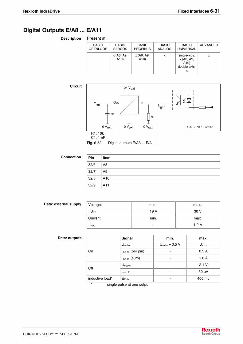
Rexroth IndraDrive Fixed Interfaces 6-31
DOK-INDRV*-CSH********-PR02-EN-P
Digital Outputs E/A8 ... E/A11Present at:
BASICOPENLOOP
BASICSERCOS
BASICPROFIBUS
BASICANALOG
BASICUNIVERSAL
ADVANCED
x (A8, A9,A10)
x (A8, A9,A10)
x single-axis:x (A8, A9,
A10)double-axis:
x
x
InOut
0 Vext Rt_X3_E_A8_11_Af2.fh7
A
24 Vext
R1
0 Vext
R1
0 Vext
C1
R1: 10kC1: 1 nF
Fig. 6-53: Digital outputs E/A8 ... E/A11
Pin Item
32/6 A8
32/7 A9
32/8 A10
32/9 A11
Voltage:
Uext
min.:
19 V
max.:
30 V
Current
Iext
min.
-
max.
1.2 A
Signal min. max.
Uout on Uext n – 0.5 V Uext n
Iout on (per pin) - 0.5 AOn
Iout on (sum) - 1.0 A
Uout off - 2.1 VOff
Iout off - 50 uA
inductive load* EPuls - 400 mJ
* single pulse at one output
Description
Circuit
Connection
Data: external supply
Data: outputs
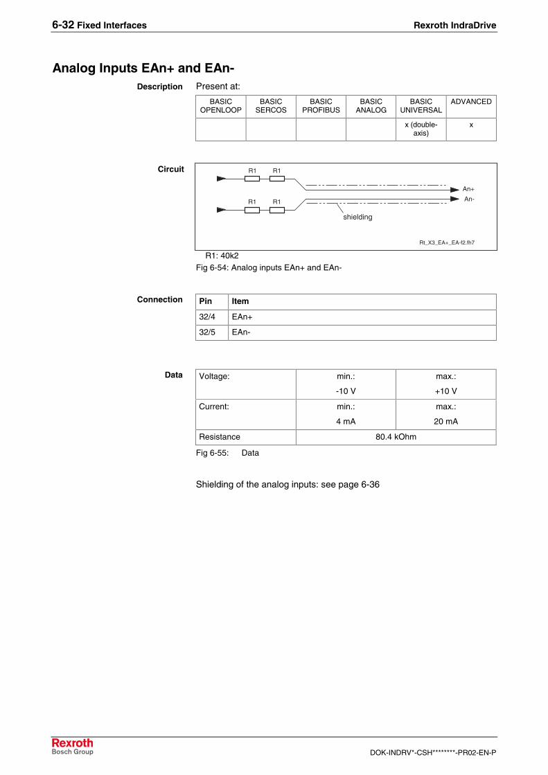
6-32 Fixed Interfaces Rexroth IndraDrive
DOK-INDRV*-CSH********-PR02-EN-P
Analog Inputs EAn+ and EAn-Present at:
BASICOPENLOOP
BASICSERCOS
BASICPROFIBUS
BASICANALOG
BASICUNIVERSAL
ADVANCED
x (double-axis)
x
Rt_X3_EA+_EA-f2.fh7
R1 R1
R1 R1
An+
An-
shielding
R1: 40k2Fig 6-54: Analog inputs EAn+ and EAn-
Pin Item
32/4 EAn+
32/5 EAn-
Voltage: min.:
-10 V
max.:
+10 V
Current: min.:
4 mA
max.:
20 mA
Resistance 80.4 kOhm
Fig 6-55: Data
Shielding of the analog inputs: see page 6-36
Description
Circuit
Connection
Data

Rexroth IndraDrive Fixed Interfaces 6-33
DOK-INDRV*-CSH********-PR02-EN-P
Analog Inputs EAn1+, EAn1-, EAn2+ and EAn2-Present at:
BASICOPENLOOP
BASICSERCOS
BASICPROFIBUS
BASICANALOG
BASICUNIVERSAL
ADVANCED
x x
Rt_X11_basic1_in.fh7
GND
RuU+
RuU-
IC
RiI+
RiI-
ICRs
U / I
Fig. 6-56: Analog inputs BASIC OPENLOOP
The analog inputs I+ and I- are on interface X36.
Rt_X11_basic4_in.fh7
RiU+
RiU-
IC
GND
Fig. 6-57: Analog inputs BASIC ANALOG
Pin Function
32/1 EAn2+: analog input 2 U+
32/2 EAn2-: analog input 2 U-
32/3 GND
32/4 EAn1+: analog input 1 U+
32/5 EAn1-: analog input 1 U-
Voltage: min.:
-10 V
max.:
+10 V
Current: min.:
0 mA
max.:
20 mA
Resistance: Ri: 80 kOhm
Rs: 200 Ohm
Resolution 12 Bit
Oversampling eight-fold
Fig. 6-58: Data
Shielding of the analog inputs: see page 6-36
Description
CircuitBASIC OPENLOOP
CircuitBASIC ANALOG
Connection
Data

6-34 Fixed Interfaces Rexroth IndraDrive
DOK-INDRV*-CSH********-PR02-EN-P
Analog Outputs An1, An2Present at:
BASICOPENLOOP
BASICSERCOS
BASICPROFIBUS
BASICANALOG
BASICUNIVERSAL
ADVANCED
x x (double-axis)
x
Rt_X32_An1_An2_GND.fh7
An1R1
R1IC
An2
GND
R2An_GND
GND
R1: 150RR2: 1R
Fig 6-59: Analog outputs An1, An2 (ADVANCED)
Rt_X32_X35_An1_An2_GND.fh7
An1
IC
An2
GND
An_GND
GND
I
I
An_GND
I: active current limiterFig. 6-60: Analog outputs An1, An2 (BASIC)
BASIC OPENLOOP:
Pin Item
32/3 An_GND
32/9 An1
35/3 An2 (see X35)
35/4 An_GND (see X35)
BASIC UNIVERSAL (double-axis); ADVANCED:
Pin Item
32/1 An1
32/2 An2
32/3 An_GND
Description
CircuitADVANCED
CircuitBASIC
Connection
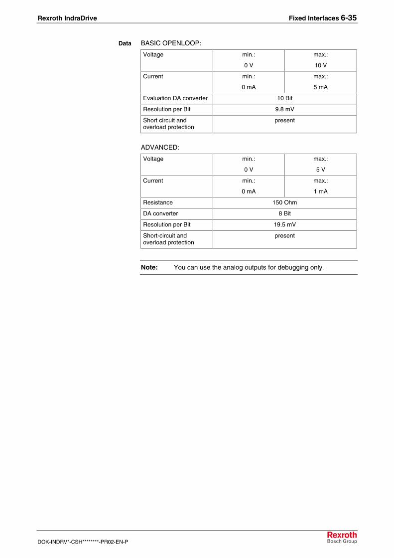
Rexroth IndraDrive Fixed Interfaces 6-35
DOK-INDRV*-CSH********-PR02-EN-P
BASIC OPENLOOP:
Voltage min.:
0 V
max.:
10 V
Current min.:
0 mA
max.:
5 mA
Evaluation DA converter 10 Bit
Resolution per Bit 9.8 mV
Short circuit andoverload protection
present
ADVANCED:
Voltage min.:
0 V
max.:
5 V
Current min.:
0 mA
max.:
1 mA
Resistance 150 Ohm
DA converter 8 Bit
Resolution per Bit 19.5 mV
Short-circuit andoverload protection
present
Note: You can use the analog outputs for debugging only.
Data

6-36 Fixed Interfaces Rexroth IndraDrive
DOK-INDRV*-CSH********-PR02-EN-P
Shielding the Analog Inputs and Outputs
analog inputs
analog outputs
RT_X32_A_anschluss.fh7
EAn+
An1An2
EAn-
XS1
X32
1b
3b4b5b6b7b8b9b
2b
GND
Fig. 6-61: Shielding the analog inputs and outputs

Rexroth IndraDrive Fixed Interfaces 6-37
DOK-INDRV*-CSH********-PR02-EN-P
Voltage Input (+24V, 0V)Present at:
BASICOPENLOOP
BASICSERCOS
BASICPROFIBUS
BASICANALOG
BASICUNIVERSAL
ADVANCED
x x x x x x
Pin Designation
31/8 +24V_ext input
31/9 0V_ext input
Voltage:
Uext
min.:
19 V
max.:
30 V
Current
Iext
min.
-
max.
1.2 A
Description
Connection
Data

6-38 Fixed Interfaces Rexroth IndraDrive
DOK-INDRV*-CSH********-PR02-EN-P
6.8 X33/X34, Digital Inputs
Present at:
BASICOPENLOOP
BASICSERCOS
BASICPROFIBUS
BASICANALOG
BASICUNIVERSAL
ADVANCED
x (double-axis)
>�� >��
���"-
���"-
Fig. 6-62: X33, X34
Type Number of poles Type of design
spring tension 2 x 6 bushings on connector
Cross sectionsingle-wire
[mm²]
Cross sectionmultiwire
[mm²]
Cross sectionin AWG
Gauge No.
-- 0.08-1.5 28-14Fig. 6-63: Connection cross section
X33 X34
E12 1 1 E18
E13 2 2 E19
E14 3 3 E20
E15 4 4 E21
E16 5 5 E22
E17 6 6 0V_extFig. 6-64: Connection Assignment
Rt_X3_E4_E7.fh7
R1
0 VE
ER1
IC
0 VE
R1: 1kFig 6-65: Digital inputs E12 ... E22
Voltage:
High
Low
min.:
15 V
-3 V
max.:
30 V
5 V
Current:
High
Low
min.:
2 mA
-
max.:
5 mA
15 mA
Fig 6-66: Data
Description
Design
Connection cross section
Connection Assignment
Circuit
Data

Rexroth IndraDrive Fixed Interfaces 6-39
DOK-INDRV*-CSH********-PR02-EN-P
6.9 X35/X36, Analog Inputs/Outputs; Voltage Output (24V, 0V)
Present at:
BASICOPENLOOP
BASICSERCOS
BASICPROFIBUS
BASICANALOG
BASICUNIVERSAL
ADVANCED
x
>�" >�-
���
���
Type Number of poles Type of design
spring tension 2 x 4 bushings on connector
Cross sectionsingle-wire
[mm²]
Cross sectionmultiwire
[mm²]
Cross sectionin AWG
Gauge No.
-- 0.08-1.5 28-14Fig. 6-67: Connection cross section
Pin Function
X35/1 voltage output (+24V)
X35/2 voltage output (0V)
X35/3 An2 (analog output 2)
X35/4 analog GND
X36/1 AI1+ (analog current input)
X36/2 AI1- (analog current input)
X36/3 AI2+ (analog current input)
X36/4 AI2- (analog current input)
Description
Design
Connection cross section
Connection assignment

6-40 Fixed Interfaces Rexroth IndraDrive
DOK-INDRV*-CSH********-PR02-EN-P
Analog Inputs
Rt_X11_basic1_in.fh7
GND
RuU+
RuU-
IC
RiI+
RiI-
ICRs
U / I
Fig. 6-68: Analog inputs
Current: min.:
0 mA
max.:
20 mA
Resistor: Ri: 80 kOhm
Rs: 200 Ohm
Fig. 6-69: Data
Analog OutputsSee interface X32
See interface X32
Voltage Output (+24V, 0V)Voltage min.:
19 V
max.:
30 V
Current - max.:
0.1 A
Protection against polarity reversal and short circuit
Note: Without an external 24V power supply the voltage outputshave to be bridged:
• bridge X35/1 with X31/8
• bridge X35/2 with X31/9
Circuit
Data
Data
Circuit
Data

Rexroth IndraDrive Fixed Interfaces 6-41
DOK-INDRV*-CSH********-PR02-EN-P
6.10 X*, Master Communication
The asterisk at the X (X*) means, that different master communicationshave different interface designations (e.g. X20/X21, X30, X15, ...).
SERCOS interface (X20, X21)Present at:
BASICOPENLOOP
BASICSERCOS
BASICPROFIBUS
BASICANALOG
BASICUNIVERSAL
ADVANCED
x o o
o = as option
X20 TX
X21 RX
LED H20
Fig. 6-70: SERCOS interface
SERCOS interface distortion LED
X20 X21
TX RX
AP5049F1.FH7
optical transmitter
X20fiber optic
cable
optical receiver
X21
SERCOS interface
fiber opticcable
device-external device-internal
Fig. 6-71: Connection
You can set the data rate and the transmission power via the controlpanel or via the serial interface X2.
Fiber Optic Cable
Drive controllers with a SERCOS interface are connected to higher-levelcontrol units by fiber optic cables.
The fiber optic cables (cable, connector, or the entire ready-made cables)have to be ordered separately.
For more detailed information on the subject of "fiber optic cables" pleaserefer to the Application Manual "LWL (Fiber Optic Cable) - Handling"(DOK-CONNEC-CABLE*LWL**-AWxx-EN-P, Part. No.: 284755).
Description
LED H20
Connection
Data Rate, Transmission Power

6-42 Fixed Interfaces Rexroth IndraDrive
DOK-INDRV*-CSH********-PR02-EN-P
The following points are dealt with in the “LWL (Fiber Optic Cable) -Handling” manual:
• General information on fiber optic cables
• Basic planning information for optical transmission systems
• Instructions for laying fiber optic cables
• Measuring attenuation on ready-made fiber optic cable
• Available fiber optic FSMA plug-in connectors and fiber optic cables
• Instructions for assembling FSMA connectors
• Tools for assembling fiber optic cables
Order details for fiber optic cable for the entire system can be ascertainedfrom the following illustration.
H3ERROR
321
X10
TX
H3ERROR
321
X10
TX
H3ERROR
321
X10
TX
H3ERROR
321
X10
TX
AP5127F1.FH7
fiber
opt
ic-
ring
CNC
SERCOSinterface
fiber optic plug-in connector(control cabinet bushing)Mat.-Nr. 252 524
ø 6
mm
ø 2mm
IKO0985 / . . . for external control cabinet installation)
length in meters
IKO0982/ . . . dependent on how the devices are arrangedIKO0982 /
length in meters
Fig. 6-72: Selection of ready-made fiber optic cables
Selection of Fiber OpticConnections

Rexroth IndraDrive Fixed Interfaces 6-43
DOK-INDRV*-CSH********-PR02-EN-P
To interconnect drive controllers of different width there are suitablecables available:
Cable Combinations of HMS, HMD and HCS03
(The width of the right drive controller determines the cablelength)
Combinations of HCS02
(The width of the left drivecontroller determines the cablelength)
50 m
m
75 m
m
100
mm
125
mm
150
mm
200
mm
225
mm
350
mm
65 m
m
105
mm
IKO0982/000,15 x x
IKO0982/000,25 x x x x
IKO0982/000,30 x
IKO0982/000,50 x x x
Fig. 6-73: Cable length
• Combination of HCS02 right besides HMS or HMD:
lwl_hcs02_hms_l
H3ERROR
321
H3ERROR
321
0����06�06)
Fig. 6-74: HCS02 right besides HMS or HMD
Cable length = 15 cm (independent from the width of the drive controllers)
Cable: IKO0982/000,15
• Combination of HCS02 left besides HMS or HMD:
lwl_hcs02_hms_r
H3ERROR
321
H3ERROR
321
0����06�06)
Abb. 6-75: HCS02 left besides HMS or HMD
Cable length = Width of HCS02 + Width of HMS/HMD + 10 cm
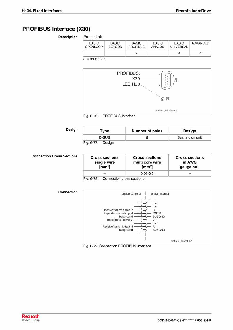
6-44 Fixed Interfaces Rexroth IndraDrive
DOK-INDRV*-CSH********-PR02-EN-P
PROFIBUS Interface (X30)Present at:
BASICOPENLOOP
BASICSERCOS
BASICPROFIBUS
BASICANALOG
BASICUNIVERSAL
ADVANCED
x o o
o = as option
profibus_schnittstelle
X30PROFIBUS:
LED H30
1
5
6
9
Fig. 6-76: PROFIBUS Interface
Type Number of poles Design
D-SUB 9 Bushing on unitFig. 6-77: Design
Cross sectionssingle wire
[mm²]
Cross sectionsmulti core wire
[mm²]
Cross sectionsin AWG
gauge no.:
-- 0.08-0.5 --Fig. 6-78: Connection cross sections
n.c.n.c.BCNTRBUSGNDVPn.c.A
Repeater control signalBusground
Receive/transmit data P
Repeater supply 5 V
Receive/transmit data N
123456789
profibus_anschl.fh7
device-external device-internal
BUSGNDBusground
Fig. 6-79: Connection PROFIBUS Interface
Description
Design
Connection Cross Sections
Connection

Rexroth IndraDrive Fixed Interfaces 6-45
DOK-INDRV*-CSH********-PR02-EN-P
Pin DIR Signal Function1 -- n.c.
2 -- n.c.
3 I/O RS485+ receive/transmit data plus
4 O CNTR-P Repeater control signal
5 0 V 0 V
6 O +5 V Repeater supply
7 -- n.c.
8 I/O RS485- receive/transmit data minus
9 0V 0 V
Fig. 6-80: Signal assignment
Via D-subminiature screws and metal connector housing.
As per DIN EN 50 170
As per DIN EN 50 170 – 2, cable type A
Signal Specification
+5 V
Repeater supply
+5 V (±10%)
max. 75 mA
Repeater control signal TTL compatible 1: transmit 0: receiveOutput resistance: 350 RVOL <= 0.8 V at IOL <= 2 mAVOH >= 3.5 V at IOH <= 1 mA
Receive/transmit data EIA-RS485 standardFig. 6-81: Signal specification
CAUTION
Danger of destroying output"+5V Repeater supply" by overload!⇒ Do not short-circuit!⇒ Do not exceed maximum current!
For the meaning of the diagnostic displays please see the FunctionalDescription of the respective firmware.
The PROFIBUS connectors each have a connectable terminatingresistor. The terminating resistor must always be active at both the firstand last bus stations. Do not interchange the A and B wires. Perform theconnection as shown in the figures below.
Plug-In Connector Assignment
Shield Connection
Interface Compatibility
Recommended Cable Type
Signal Specification
Diagnostic Display
Bus Connector

6-46 Fixed Interfaces Rexroth IndraDrive
DOK-INDRV*-CSH********-PR02-EN-P
AP5069f1.fh7
OF
F
ON
OF
F
ON
Bus connection and switchposition for the first and last stations
Bus connection and switchposition for all other stations
shield
A1 B1 A2 B2
5 16 5
A1 B1 A2 B2
Fig. 6-82: Preparing a cable for connecting a bus connector
To prepare a bus cable, proceed as follows:
• Use cable DIN EN50170 / 2 edition 1996
• Strip cable (see previous illustration)
• Insert both cores into screw terminal block
Note: Do not interchange the cores for A and B.
• Press cable sheath between both clamps
• Screw both strands into screw terminals
Ap5074f1.fh7
1
2
1
2
A BA B
A BA B
Siem
ens
onof
f
Siem
ens
Switch connection for the first and final slave in the Profibus-DP
The cable shield must be placed bare on the metal guide
Fig. 6-83: Bus connection for the first and last slave, bus connector with 9-pinD-SUB socket, INS 0541

Rexroth IndraDrive Fixed Interfaces 6-47
DOK-INDRV*-CSH********-PR02-EN-P
Sie
men
s
Sie
men
s
Ap5075f1.fh7
1
2
1
2
A BA B
A BA B
Sie
men
s
onof
f
Sie
men
s
Terminating resistor is offThe cable shield must be placed bare on the metal guide
Fig. 6-84: Bus connection for all other slaves, bus connector with 9-pin D-SUBsocket, INS 0541
Ap5076f1.fh7
2
1
2
A BA B
A BA B
Siem
ens
Siem
ens
1
onoff
Switch connection for the first and final slave in the Profibus-DP
The cable shield must be placed bare on the metal guide
Fig. 6-85: Bus connection for the first and last slave without 9-pin D-SUBsocket, INS 0540
Sie
men
s
Sie
men
s
Ap5077f1.fh7
1
2
1
2
A BA B
A BA B
Sie
men
s
onoff
Sie
men
s
Terminating resistor is offThe cable shield must be placed bare on the metal guide
Fig. 6-86: Bus connection for all other slaves without 9-pin D-SUB socket, INS0540
Connect the drive controller to a control unit using a shielded two-wireconductor in accordance with DIN 19245/ section 1.

6-48 Fixed Interfaces Rexroth IndraDrive
DOK-INDRV*-CSH********-PR02-EN-P
Parallel Interface (X15)Present at:
BASICOPENLOOP
BASICSERCOS
BASICPROFIBUS
BASICANALOG
BASICUNIVERSAL
ADVANCED
o o
o = as option
(Internal designation of this master communication card: HCC01)
d-sub-37-stiftf2.FH7
19
1 20
37
Fig. 6-87: Interface
Type Number of poles Type of design
D-SUB 37 pins on deviceFig. 6-88: Design
Cross sectionsingle-core
[mm²]
Cross sectionmulti-core
[mm²]
Cross sectionin AWG
gauge No.
-- 0.08-0.5 --Fig. 6-89: Connection cross section
Description
Design
Connection Cross Section

Rexroth IndraDrive Fixed Interfaces 6-49
DOK-INDRV*-CSH********-PR02-EN-P
Pin I/O Function Pin I/O Function
1 I Input 0.0 20 I Input 0.1
2 I Input 0.2 21 I Input 0.3
3 I Input 1.0 22 I Input 1.1
4 I Input 1.2 23 I Input 1.3
5 I Input 2.0 24 I Input 2.1
6 I Input 2.2 25 I Input 2.3
7 I Input 3.0 26 I Input 3.1
8 I Input 3.2 27 I Input 3.3
9 PWR GNDext 28 O Output 0.0
10 O Output 0.1 29 O Output 0.2
11 O Output 0.3 30 PWR Uext 0
12 O Output 1.0 31 O Output 1.1
13 O Output 1.2 32 O Output 1.3
14 PWR Uext 1 33 O Output 2.0
15 O Output 2.1 34 O Output 2.2
16 O Output 2.3 35 PWR Uext 2
17 O Output 3.0 36 O Output 3.1
18 O Output 3.2 37 O Output 3.3
19 - Uext 3
Fig. 6-90: Signal assignment
• Uext 0 supplies Output 0.0 to 0.3 and Input 0.0 to 0.3
• Uext 1 supplies Output 1.0 to 1.3 and Input 1.0 to 1.3
• Uext 2 supplies Output 2.0 to 2.3 and Input 2.0 to 2.3
• Uext 3 supplies Output 3.0 to 3.3 and Input 3.0 to 3.3
• Ground GNDext is common for all I/Os
• Shield connection via metallized connector housing
• Inputs and outputs are electrically isolated from the control section
• Inputs are protected against inverse-polarity
• Outputs are short-circuit proof
Voltage:
Uext n
min.:
19 V
max.:
30 V
Current
Iext n
min.
-
max.
1.2 A
Fig. 6-91: Data: supply
The external supply is also necessary, when only the digital inputs areused.
Assignment
Features
Data: External Supply

6-50 Fixed Interfaces Rexroth IndraDrive
DOK-INDRV*-CSH********-PR02-EN-P
Signal min. max.
Uin n.m on 15 V 30 VOn
Iin n.m on 2 mA 5 mA
Uin n.m off -3 V 5 VOff
Iin n.m off - 15 mA
Fig. 6-92: Data: inputs
Signal min. max.
Uout n.m on Uext n – 0.5 V Uext n
Iout n.m on (per pin) - 0.5 AOn
Iout n on (per pin) - 1.0 A
Uout n.m off - 2.1 VOff
Iout n.m off - 50 uA
Inductive load* EPuls - 400 mJ
* single pulse at one outputFig. 6-93: Data: outputs
The outputs are High-Side Switches. They are current-sourcing and notcurrent-sinking.
Data: Inputs
Data: Outputs

Rexroth IndraDrive Fixed Interfaces 6-51
DOK-INDRV*-CSH********-PR02-EN-P
6.11 H1 (Control Panel)
The control panel is plugged into the H1 interface on the control section.
1
2
3
4
5
6
7
8
H1
Fig. 6-94: H1
�5��� ����� �� �� �� ����
Fig. 6-95: Control panel at drive controller
Connection

6-52 Fixed Interfaces Rexroth IndraDrive
DOK-INDRV*-CSH********-PR02-EN-P
Esc Enter
01.F4002
Fig. 6-96: Standard control panel with sample display and control elements
• Operating status, command and error diagnoses, and warnings forproblems requiring attention are shown in the display.
• Using the four buttons, the commissioning operator or serviceengineer can opt, in addition to master communication using thecommissioning tool or NC control, to display further diagnoses on thedrive controller and to activate simple commands.
Using the control panel you can:
• set the drive address
• SERCOS: set the transmitting power
• SERCOS Autodetect: set field bus transmission rate
• establish reference dimension
• look at the error memory
• start basic load defaults procedure
• set analog outputs
Note: For detailed information refer to your firmware documentation.
Design
Overview of Functions

Rexroth IndraDrive Options 7-1
DOK-INDRV*-CSH********-PR02-EN-P
7 Options
7.1 Overview
BASIC SERCOS
basic_sercos_optionen
X41
X41: L1 Starting LockoutFig. 7-1: BASIC SERCOS

7-2 Options Rexroth IndraDrive
DOK-INDRV*-CSH********-PR02-EN-P
BASIC PROFIBUS
basic_profibus_optionen
X41
X41: L1 Starting LockoutFig. 7-2: BASIC PROFIBUS

Rexroth IndraDrive Options 7-3
DOK-INDRV*-CSH********-PR02-EN-P
BASIC ANALOG
basic_analog_optionen
X41
X41: L1 Starting LockoutFig. 7-3: BASIC ANALOG

7-4 Options Rexroth IndraDrive
DOK-INDRV*-CSH********-PR02-EN-P
BASIC UNIVERSAL
basic_universal_optionen
X41
X4
basic_universal_doppelachs_optionen.fh7
X8.1
X4.2
X8.2
X4.1
X41.2X41.1
Single-axis:X4: Option 2X41 Safety option
Double-axis:X4.1: Option 1X4.2: Option 2X8.1: Option 3X8.2: Option 4X41.1, X41.2: Safety option
Fig. 7-4: BASIC UNIVERSAL
Concerning the designations "Option 1...4" and "Safety option" seechapter 4.2.

Rexroth IndraDrive Options 7-5
DOK-INDRV*-CSH********-PR02-EN-P
ADVANCED
advanced_optionen
X10
X41
X8 X4
X4: Option 1X41: Safety optionX8: Option 2X10: Option 3
Fig. 7-5: ADVANCED
Concerning the designations "Option 1...3" and "Safety option" seechapter 4.2.

7-6 Options Rexroth IndraDrive
DOK-INDRV*-CSH********-PR02-EN-P
Reference to Description of Options
Encoder Interface• EN1: HSF, Resolver:
see page 7-7
• EN2: EnDat2.1, 1Vss, 5VTTL:see page 7-11
• ENS: IndraDyn, HIPERFACE®, 1Vss:see page 7-18
• MEM: Encoder emulator module:see page 7-19
Integrated Safety Technology• L1: starting lockout:
see page 7-20
• S1: safety technology I/O:see page 7-22
I/O Extension• MD1: digital input/output extension:
see page 7-24
• MA1: analog input/output extension:see page 7-27
Note: Your sales representative will help with the current status ofavailable options.

Rexroth IndraDrive Options 7-7
DOK-INDRV*-CSH********-PR02-EN-P
7.2 Encoder
EN1: HSF, ResolverPresent at:
BASICOPENLOOP
BASICSERCOS
BASICPROFIBUS
BASICANALOG
BASICUNIVERSAL
ADVANCED
x x
Encoder with control voltage supply of 8 volt:
• HSF (Digital servo feedback)
• Resolver
(Internal designation of the option: HFI01)
BASIC UNIVERSAL: X4 resp.X4.1 (1. axis)X4.2 (2. axis)
ADVANCED: X4, X8 or X10
Type Number of poles Design
D-SUBMINIATURE 15 Bushing on unit
d-sub-15-buchsef1.FH7
1
8
9
15
Fig. 7-6: D-SUBMINIATURE bushing
Cross sectionsingle-wire
[mm²]
Cross sectionmultiwire
[mm²]
Cross sectionin AWG
Gauge No.
-- 0.25 - 0.5 --Fig. 7-7: Connection cross section
Description
Slot
Design
Connection Cross Section
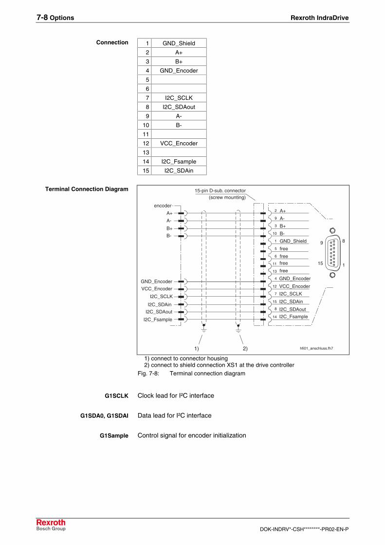
7-8 Options Rexroth IndraDrive
DOK-INDRV*-CSH********-PR02-EN-P
1 GND_Shield
2 A+
3 B+
4 GND_Encoder
5
6
7 I2C_SCLK
8 I2C_SDAout
9 A-
10 B-
11
12 VCC_Encoder
13
14 I2C_Fsample
15 I2C_SDAin
hfi01_anschluss.fh7
1
89
15
2
9
3
10
1
5
6
A+
A-
B+
B-
GND_Shield
free
free
11
13
encoder
free
4 GND_EncoderGND_Encoder
A+
A-
B+
B-
I2C_Fsample14 I2C_Fsample
I2C_SDAin15 I2C_SDAin
VCC_Encoder 12 VCC_Encoder
I2C_SDAout8 I2C_SDAout
I2C_SCLK7 I2C_SCLK
15-pin D-sub. connector(screw mounting)
free
1) 2)
1) connect to connector housing2) connect to shield connection XS1 at the drive controller
Fig. 7-8: Terminal connection diagram
Clock lead for I²C interface
Data lead for I²C interface
Control signal for encoder initialization
Connection
Terminal Connection Diagram
G1SCLK
G1SDA0, G1SDAI
G1Sample

Rexroth IndraDrive Options 7-9
DOK-INDRV*-CSH********-PR02-EN-P
AP5296F1.FH7
R1
R4R2
R3
-
+
E+E-
C2
C1
SchematicsR1: 5kR2: 5kR3: 20k (HSF) resp. 2k5 (resolver)R4: 20k (HSF) resp. 2k5 (resolver)C1: no dataC2: no data
Fig. 7-9: Input circuit
Features of the differential input circuit:
Digital servofeedback
Resolver
max. allowed amplitudeencoder signal
(1.0 + 0.1) Vpp 9.0 Vpp
evaluationAD converter
12 bit 12 bit
limit frequency (-3 dB) 100 kHz --
input resistance 10k ±5%Fig. 7-10: Features of the differential input circuit
Features of the encoder output amplifier stage VCC_Encoder:
Digital servofeedback
Resolver
output voltage 8 VDC ± 0.2V 18.2 Vpp(sine with 4 kHz)
max. output current DC 250 mA AC 70 mA eff.
min. DC resistance ofthe load
-- 35R
Fig. 7-11: Features of the encoder output amplifier stage
Input Circuit A+, A- resp. B+, B-
VCC_Encoder

7-10 Options Rexroth IndraDrive
DOK-INDRV*-CSH********-PR02-EN-P
Signal Assignment to the Actual Position Value
Signal assignment Signal designation Signal form Actual position value(with default setting)
A+
A-
B+
B-
HSF(sine 1 Vpp without
120 Ohm matching resistor,I²C bus)
increasing
amplitude-modulated signal
A+
A-
B+
B-
resolver increasing
Fig. 7-12: Signal assignment to the actual position value

Rexroth IndraDrive Options 7-11
DOK-INDRV*-CSH********-PR02-EN-P
EN2: EnDat2.1, 1Vss, 5VTTLPresent at:
BASICOPENLOOP
BASICSERCOS
BASICPROFIBUS
BASICANALOG
BASICUNIVERSAL
ADVANCED
x x
Encoder with control voltage supply of 5 volt:
• EnDat2.1 with sensor connection
• sine encoder (1 Vpp) with reference track
• square-wave encoder (TTL) with reference track
(Internal designation of the option: HFI02)
BASIC UNIVERSAL: X4X4.1 (1. axis)X4.2 (2. axis)
ADVANCED: X4, X8 or X10
Type Number of poles Design
D-SUBMINIATURE 15 pins on unit
d-sub-15-stiftf2.FH7
8
1 9
15
Fig. 7-13: D-subminiature connector
Cross sectionsingle-wire
[mm²]
Cross sectionmultiwire
[mm²]
Cross sectionin AWG
Gauge No.
-- 0.25 - 0.5 --Fig. 7-14: Connection cross section
Description
Slot
Design
Connection Cross Section
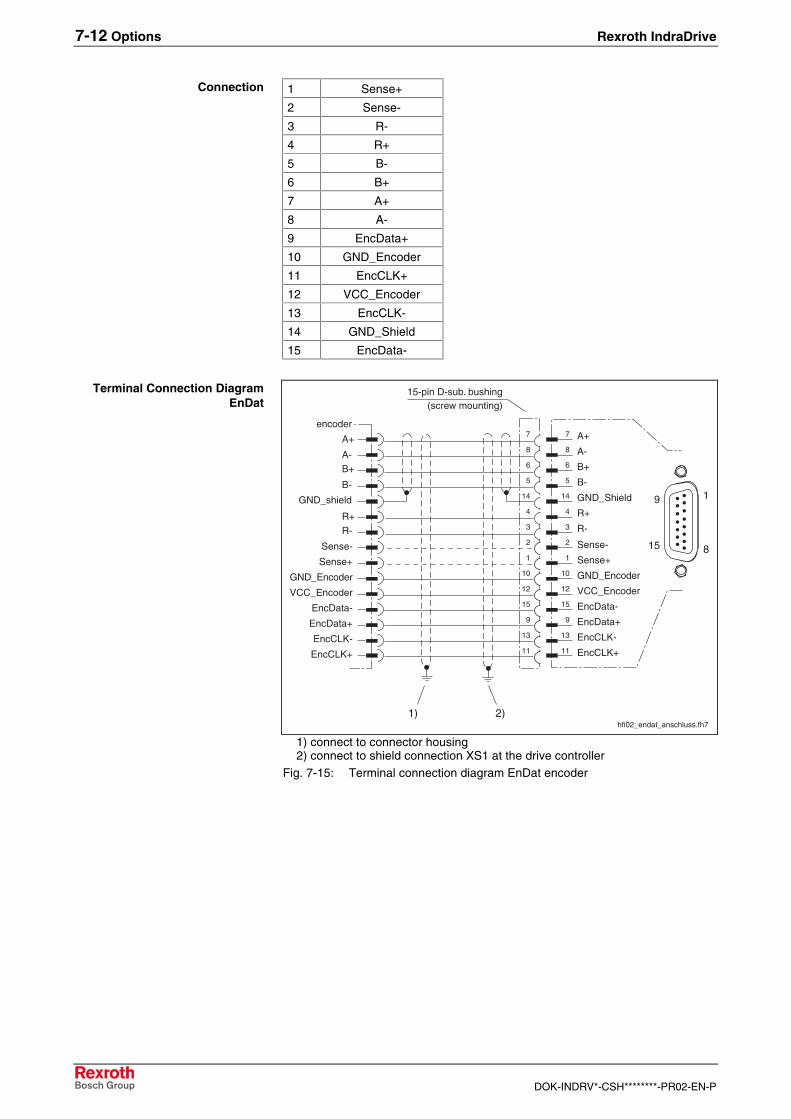
7-12 Options Rexroth IndraDrive
DOK-INDRV*-CSH********-PR02-EN-P
1 Sense+
2 Sense-
3 R-
4 R+
5 B-
6 B+
7 A+
8 A-
9 EncData+
10 GND_Encoder
11 EncCLK+
12 VCC_Encoder
13 EncCLK-
14 GND_Shield
15 EncData-
hfi02_endat_anschluss.fh7
7
8
6
5
14
4
3
2
1
10
12
15
9
13
11
8
19
15
7
8
6
5
14
4
3
2
1
10
12
15
9
13
11
15-pin D-sub. bushing(screw mounting)
encoder
A+
A-B+
B-
GND_shield
R+R-
1) 2)
A+
A-
B+
B-
GND_Shield
R+
R-
Sense-
Sense+
GND_Encoder
VCC_Encoder
EncData-
EncData+
EncCLK-
EncCLK+
Sense-
Sense+
GND_Encoder
VCC_Encoder
EncData-
EncData+
EncCLK-
EncCLK+
1) connect to connector housing2) connect to shield connection XS1 at the drive controller
Fig. 7-15: Terminal connection diagram EnDat encoder
Connection
Terminal Connection DiagramEnDat

Rexroth IndraDrive Options 7-13
DOK-INDRV*-CSH********-PR02-EN-P
hfi02_rechteck_anschluss.fh7
7
8
6
5
14
4
3
2
1
10
12
15
9
13
11
8
19
15
7
8
6
5
14
4
3
2
1
10
12
15
9
13
11
encoder
A+
A-B+
B-
R+R-
GND_Encoder
VCC_Encoder
15-pin D-sub. bushing(screw mounting)
1) 2)
A+
A-
B+
B-
GND_Shield
R+
R-
Sense-
Sense+
GND_Encoder
VCC_Encoder
EncData-
EncData+
EncCLK-
EncCLK+
1) connect to connector housing2) connect to shield connection XS1 at the drive controller
Fig. 7-16: Terminal connection diagram square-wave encoder
hfi02_sinus_anschluss.fh7
7
8
6
5
14
4
3
2
1
10
12
15
9
13
11
8
19
15
7
8
6
5
14
4
3
2
1
10
12
15
9
13
11
encoder
A+
A-B+
B-
R+R-
GND_Encoder
VCC_Encoder
15-pin D-sub. bushing(screw mounting)
GND_Shield
1) 2)
A+
A-
B+
B-
GND_Shield
R+
R-
Sense-
Sense+
GND_Encoder
VCC_Encoder
EncData-
EncData+
EncCLK-
EncCLK+
1) connect to connector housing2) connect to shield connection XS1 at the drive controller
Fig. 7-17: Terminal connection diagram sine encoder
Differential signal of the encoder data lead.
Differential signal of the encoder pulse lead.
Terminal Connection DiagramSquare-Wave Encoder
Terminal Connection DiagramSine Encoder
EncData+, EncData-
EncCLK+, EncCLK-

7-14 Options Rexroth IndraDrive
DOK-INDRV*-CSH********-PR02-EN-P
hfi02_sin_ein_schalt.FH7
E+
E-120R
Block diagramFig. 7-18: Input circuit for sine signals
hfi02_recht_ein_schalt.FH7
E+
E-120R
A
B
Block diagramFig. 7-19: Input circuit for square-wave signals
Features of the differential input:
Input voltage
max. allowed amplitude encoder signal(USSencoder signal)
(1.0 + 0.2) Vpp
evaluation AD converter 12 bit
limit frequency (-3 dB) 500 kHz
input resistance 120RFig. 7-20: Features of the differential input (Sine encoder)
Input voltage
Signal amplitude nominal:(referencing unit ground)
High
Low
min.
> 2.4 V
0 V
max.
5 V
< 0.8 V
limit frequency 500 kHz
input resistance 120RFig. 7-21: Features of the differential input (square-wave encoder)
Returning encoder supply to amplifier so that the voltage drop in theencoder cable can be regulated and 5 V are always present in theencoder independent of the cable length.
Features of the encoder output amplifier stage VCC_Encoder:
output voltage 5 VDC
max. output current 300 mAFig. 7-22: Features of the encoder output amplifier stage
Input Circuit for Sine SignalsA+, A- resp. B+, B- resp- R+, R-
Input Circuit for Square-WaveSignals
Sine Encoder
Square-Wave Encoder
Sense+, Sense-
VCC_Encoder

Rexroth IndraDrive Options 7-15
DOK-INDRV*-CSH********-PR02-EN-P
Signal Assignment to the Actual Position Value
Signal assignment Signal designation Signal form Actual position value(with default setting)
A+
A-
B+
B-
R+
R-
sine (1Vpp)without absolute value decreasing
A+
A-
B+
B-
R+
R-
square (TTL)without absolute value
decreasing
A+
A-
B+
B-
sine (1 Vpp)with absolute value increasing
Fig. 7-23: Signal assignment to the actual position value
Note: Default setting:=> see Functional Description of firmware

7-16 Options Rexroth IndraDrive
DOK-INDRV*-CSH********-PR02-EN-P
Allowed Encoder Cable Lengths
Note: The current consumption of the connected encoder systemsgenerates a voltage drop due to the ohmic resistance of thewire (dependent upon the wire cross sections and lengths).This reduces the signal at the encoder input.
To compensate the voltage drop, the drive controller caninfluence the encoder power source. Using a voltage sensor,the available voltage at the encoder is detected.
⇒ For a given wire length and encoder current consumption, a minimumcross section becomes necessary. This relationship is illustratedbelow.
Note: When you use original Heidenhain cables the allowed cablelength is much shorter.
1. Cable length with sensor connection in the encoder lead
• wire cross section: 0.5 mm2
• power supply: 5 V ±5%
hfi02_kabel_5_m_sense.fh7
�
"
�
"
��
�"
��
�"
��
�"
"�
""
-�
-"
�
"
� "� �� "� ��� �"� ��� �"�
! ��&%"�!�%' -+"$�%�6-�7
0&%("1�6-
7
L: cable lengthI: currentA: wire cross sections
Fig. 7-24: Cable lengths with sensor connection
Selecting wire cross sections

Rexroth IndraDrive Options 7-17
DOK-INDRV*-CSH********-PR02-EN-P
2. Cable length without sensor connection in the encoder lead
• wire cross section: 0.5 mm2
• power supply: 5 V ±5%
hfi02_kabel_5_o_sense.fh7
�
"
�
"
��
�"
��
�"
��
�"
"�
�� "� ��� �"� ��� �"�
! ��&%"�!�%' -+"$�%�6-�7
0&%("1�6-
7
Fig. 7-25: Cable lengths without sensor connection
7-18 Options Rexroth IndraDrive
DOK-INDRV*-CSH********-PR02-EN-P
ENS: 1Vpp; HIPERFACE®, IndraDyn
Present at:
BASICOPENLOOP
BASICSERCOS
BASICPROFIBUS
BASICANALOG
BASICUNIVERSAL
ADVANCED
x x
Encoder with control voltage supply of 12 volt:
• 1 Vppwith reference track
• 1 Vpp with HIPERFACE®
• IndraDyn (encoder interface of MSK motors)
(Internal designation of the option: HFI03)
BASIC UNIVERSAL: X4X4.1 (1. axis)X4.2 (2. axis)
ADVANCED: X4, X8 or X10
see chapter 6.4 X8, ENS (Encoder Interface)
Description
Slot
Further information

Rexroth IndraDrive Options 7-19
DOK-INDRV*-CSH********-PR02-EN-P
MEM: Encoder Emulator ModulePossible with:
BASICOPENLOOP
BASICSERCOS
BASICPROFIBUS
BASICANALOG
BASICUNIVERSAL
ADVANCED
x 1) x x
1) Designed as fixed interface X16
(Internal designation of the option: HFE01)
BASIC: X4 resp.X8.1 (1. axis)X8.2 (2. axis)
ADVANCED: X8 or X10
See chapter 6.6 X16, Encoder Emulation
Description
Slot
Further information

7-20 Options Rexroth IndraDrive
DOK-INDRV*-CSH********-PR02-EN-P
7.3 Integrated Safety Technology
The options of Integrated Safety Technology allow operation of drives insafe conditions according to EN954-1 category 3.
Note: The Integrated Safety Technology is described in detail in anextra documentation (see page 1-1).
L1: Starting Lockout
Possible with:
BASICOPENLOOP
BASICSERCOS
BASICPROFIBUS
BASICANALOG
BASICUNIVERSAL
ADVANCED
x x x x x
The Starting Lockout meets stop category 0 according to EN 60204-1.
(Internal designation of the option: HSI01)
X41
Type Number of poles Type of design
D-SUB 9 bushing on unit
d-sub9-buchsef1.FH7
"
-
:
Fig. 7-26: D-SUB socket
Cross sectionsingle-core
[mm²]
Cross sectionmulti-core
[mm²]
Cross sectionin AWG
gauge No.
-- 0.25 – 0.5 --Fig. 7-27: Connection cross section
Description
Slot
Design
Connection Cross Section

Rexroth IndraDrive Options 7-21
DOK-INDRV*-CSH********-PR02-EN-P
Meaning Signal Pin
Controlling signal for starting lockout assignment A AS-A 1
Inverted controlling signal for starting lockout ASn 2
Controlling signal for starting lockout assignment B AS-B 3
Supply for acknowledgment potential ASQ 4
Acknowledgment ASQ1 5
Inverted acknowledgment ASQ2 6
not used - 7
24 V supply voltage +24 VE 8
Reference potential of the 24 V supply voltage 0VE 9
AS ASn Status ASQ1 ASQ2
1 0 Starting lockout active = ASQ open
0 1 Starting lockout not active open = ASQ
0 0
1 1
Error when selecting starting lockout open = ASQ
min. typ. max. Note
Input voltage:
On
Off
Switching threshold
+15 V
-3 V
+8 V
+30 V
+5 V
acc. toEN61131
Input current
Inputs AS, ASn 5 mA
Load capacity of relaycontact ASQ, ASQ1,ASQ2
1000 mA
24 V
not short-circuit proof
Supply voltage +22.8 V +24 V +25.2 V acc. toEN61131
Fig. 7-28: Data
Connection Assignment
Function
Data

7-22 Options Rexroth IndraDrive
DOK-INDRV*-CSH********-PR02-EN-P
S1: Safety Technology I/O
Possible with:
BASICOPENLOOP
BASICSERCOS
BASICPROFIBUS
BASICANALOG
BASICUNIVERSAL
ADVANCED
x
This module allows different application related safety functions like safetyrelated standstill, safety related drive interlock, safety related reducedspeed, safety related direction of motion and further functions.
Note: This module can only be used in connection with an encoder.
(Internal designation of the option: HSI11)
X41
Type Number of poles Type of design
D-SUB 9 bushing on unit
d-sub9-buchsef1.FH7
"
-
:
Fig. 7-29: D-SUB socket
Cross sectionsingle-core
[mm²]
Cross sectionmulti-core
[mm²]
Cross sectionin AWG
gauge No.
-- 0.25 - 0.5 --Fig. 7-30: Connection cross section
Pin Signal Meaning
1 EA30 Input/output for forced dynamization
2 EA20 Input/output for acknowledgment
3 EA10n Input/output for diagnostic message/safety door lockingdevice
4 E1n
5 E2n
6 E3n
7 E4n
Inputs for operating mode selection
8 +24VE 24 V supply voltage
9 0 VE Reference potential of the 24 V supply voltage
Description
Slot
Design
Connection Cross Section
Connection Assignment
udo0stei
S. 7-22 Connection assignment: Statt EAx und Ex besser englisch IOx und Ix

Rexroth IndraDrive Options 7-23
DOK-INDRV*-CSH********-PR02-EN-P
min. typ. max. Note
Inputs/outputs
Input voltage:
On
Off
Switching threshold
+15 V
-3 V
+8 V
+30 V
+5 V
acc. toEN61131
Input current
Inputs E1n, E2n, E3n, E4n
3 mA
Input current
Input/output EA10n, EA30 EA20
3 mA6 mA
Load capacity of relay contactEA10
1000mA
24 V
not short-circuit proof
Driver output currentInput/output
EA10n, EA20, EA30
500 mA short-circuitproof
Internal voltage drop high-sidedriver
2 V at IOUT =500 mA
Supply voltage +22.8 V +24 V +25.2 V acc. toEN61131
Dynamization pulse EA30
tW
tP
tD
100 ms
1000 ms
50 ms
programmable
(firmware)
Toggle frequency EA20
fTOGGEL
500 Hz programmable
(firmware)
Interrupting circuit for voltage supply of the control optocouplers
Dynamization pulse
tWK2
tPK2
tDK2
2 us 20 us
1000 us
tWK2
30 us
programmable
(firmware)
Encoder evaluation
Additional load resistance ofencoder signals
20kOhm
Resolution of AD converter 10 bit
Converting time of AD converterper channel
10 us
Input frequency 500 kHz
Minimum edge distance betweenactive edges
250 ns
General
Number of drives in a drivesystem
25
Fig. 7-31: Data
Data

7-24 Options Rexroth IndraDrive
DOK-INDRV*-CSH********-PR02-EN-P
7.4 MD1: Digital Input/Output Extension
Possible with:
BASICOPENLOOP
BASICSERCOS
BASICPROFIBUS
BASICANALOG
BASICUNIVERSAL
ADVANCED
x
8 digital 24V outputs and 12 digital 24V inputs according to IEC61131.
(Internal designation of the option: HEA01)
X10
d-sub-25-stiftf2.FH7
13
1 14
25
Fig. 7-32: Interface
Type Number of poles Design
D-SUB 25 Pins on unitFig. 7-33: Design
Cross sectionssingle wire
[mm²]
Cross sectionsmulti core wire
[mm²]
Cross sectionsin AWG
gauge no.:
-- 0.08-0.5 --Fig. 7-34: Connection cross sections
Description
Slot
Design
Connection Cross Section

Rexroth IndraDrive Options 7-25
DOK-INDRV*-CSH********-PR02-EN-P
Pin I/O Function Pin I/O Function
1 O Output 0.0 14 I Input 2.0
2 O Output 0.1 15 I Input 2.1
3 PWR Uext 0 16 I Input 2.2
4 O Output 0.2 17 I Input 2.3
5 O Output 0.3 18 I Input 2.4
6 PWR GNDext 19 I Input 2.5
7 PWR Uext 2 20 I Input 2.6
8 PWR GNDext 21 I Input 2.7
9 O Output 1.0 22 I Input 2.8
10 O Output 1.1 23 I Input 2.9
11 PWR Uext 1 24 I Input 2.10
12 O Output 1.2 25 I Input 2.11
13 O Output 1.3Fig. 7-35: Signal assignment
• Uext 0 supplies Output 0.0 to 0.3
• Uext 1 supplies Output 1.0 to 1.3
• Uext 2 supplies Input 2.0 to 2.11
• Ground GNDext (2 Pins) is common for all I/Os
• Shield connection via metallized connector housing
• Inputs and outputs are electrically isolated from the control section
• Inputs are protected against inverse-polarity
• Outputs are short-circuit proof
Voltage:
Uext
min.:
19 V
max.:
30 V
Current
Iext 0, Iext 1
Iext 2
min.
-
-
max.
1.2 A
0.1 A
Fig. 7-36: Data: external supply
Voltage:
On
Off
min.:
15 V
-3 V
max.:
30 V
5 V
Current:
On
Off
min.:
2 mA
-
max.:
5 mA
15 mA
Fig. 7-37: Data: Inputs
Plug-In Connector Assignment
Features
Data: External Supply
Data: Inputs
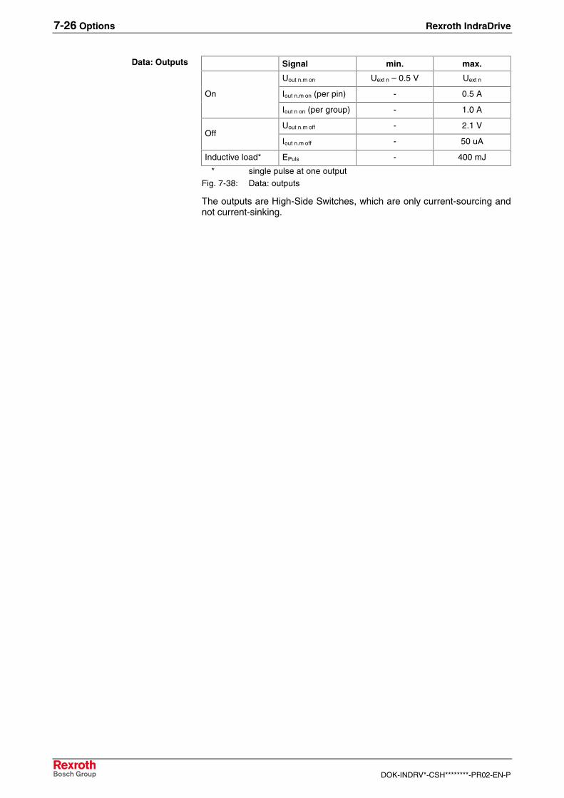
7-26 Options Rexroth IndraDrive
DOK-INDRV*-CSH********-PR02-EN-P
Signal min. max.
Uout n.m on Uext n – 0.5 V Uext n
Iout n.m on (per pin) - 0.5 AOn
Iout n on (per group) - 1.0 A
Uout n.m off - 2.1 VOff
Iout n.m off - 50 uA
Inductive load* EPuls - 400 mJ
* single pulse at one outputFig. 7-38: Data: outputs
The outputs are High-Side Switches, which are only current-sourcing andnot current-sinking.
Data: Outputs

Rexroth IndraDrive Options 7-27
DOK-INDRV*-CSH********-PR02-EN-P
7.5 MA1: Analog Input/Output Extension
Possible with:
BASICOPENLOOP
BASICSERCOS
BASICPROFIBUS
BASICANALOG
BASICUNIVERSAL
ADVANCED
x x
2 analog input channels (12 bit); 2 analog output channels (12 bit)
(Internal designation of the option: HAS01)
X10
d-sub-15-buchsef1.FH7
1
8
9
15
Fig. 7-39: Interface
Type Number of poles Design
D-SUB 15 Bushing on unitFig. 7-40: Design
Cross sectionssingle wire
[mm²]
Cross sectionsmulti core wire
[mm²]
Cross sectionsin AWG
gauge no.:
-- 0.08-0.5 --Fig. 7-41: Connection cross sections
Description
Slot
Design
Connection Cross Section

7-28 Options Rexroth IndraDrive
DOK-INDRV*-CSH********-PR02-EN-P
Pin Signal I/O Function
1 GND100 - Shield analog input AE1
2 +AE1 I Analog input 1 (+)
3 GND100 - Shield analog input AE2
4 +AE2 I Analog-input 2 (+)
5 AA1 O Analog output 1 (+)
6 GNDA - Shield analog output AA1(to be used optionally in case of extremeinterferences)
7 GND100 - Shield analog input AA2
8 Earth - Connector housing
9 -AE1 I Analog input 1 (-)
10 GNDA - Shield analog input AE1(to be used optionally in case of extremeinterferences)
11 -AE2 I Analog input 2 (-)
12 GNDA - Shield analog output AE2(to be used optionally in case of extremeinterferences)
13 GND100 - Shield analog output AA1
14 AA2 O Analog output 2 (+)
15 GNDA - Shield analog output AA2(to be used optionally in case of extremeinterferences)
8 Housing15 GNDA7 GND100
14 +AA26 GNDA13 GND100
5 +AA112 GNDA4 +AE211 - AE23 GND100
10 GNDA2 +AE19 - AE11 GND100
815 714 613 512 411 310 29 1
Fig. 7-42: Connector assignment
Connector Assignment

Rexroth IndraDrive Options 7-29
DOK-INDRV*-CSH********-PR02-EN-P
Voltage min.:
-10 V
max.:
+10 V
A/D converter 12 bit
Increments 5 mV / increment
Fig. 7-43: Data: inputs
external source ofsignals
MA1
NT
100R
optional (in case ofextreme interferences)
Fig. 7-44: Analog input: possibility of connection
Voltage min.:
-10 V
max.:
+10 V
D/A converter 12 bit
Increments 5 mV / increment
Fig. 7-45: Data: outputs
external receiverMA1
100R
optional (in case ofextreme interferences)
Data: Inputs
Analog Input:Possibility of Connection
Data: Outputs
Analog Output:Possibility of Connection

7-30 Options Rexroth IndraDrive
DOK-INDRV*-CSH********-PR02-EN-P
Notes

Rexroth IndraDrive Service & Support 8-1
DOK-INDRV*-CSH********-PR02-EN-P
8 Service & Support
8.1 Helpdesk
Unser Kundendienst-Helpdesk im Hauptwerk Lohram Main steht Ihnen mit Rat und Tat zur Seite.Sie erreichen uns
Our service helpdesk at our headquarters in Lohr amMain, Germany can assist you in all kinds of inquiries.Contact us
- telefonisch - by phone: 49 (0) 9352 40 50 60über Service Call Entry Center Mo-Fr 07:00-18:00- via Service Call Entry Center Mo-Fr 7:00 am - 6:00 pm
- per Fax - by fax: +49 (0) 9352 40 49 41
- per e-Mail - by e-mail: [email protected]
8.2 Service-Hotline
Außerhalb der Helpdesk-Zeiten ist der Servicedirekt ansprechbar unter
After helpdesk hours, contact our servicedepartment directly at
+49 (0) 171 333 88 26
oder - or +49 (0) 172 660 04 06
8.3 Internet
Unter www.boschrexroth.com finden Sieergänzende Hinweise zu Service, Reparatur undTraining sowie die aktuellen Adressen *) unsererauf den folgenden Seiten aufgeführten Vertriebs-und Servicebüros.
Verkaufsniederlassungen
Niederlassungen mit Kundendienst
Außerhalb Deutschlands nehmen Sie bitte zuerst Kontakt mitunserem für Sie nächstgelegenen Ansprechpartner auf.
*) Die Angaben in der vorliegenden Dokumentation könnenseit Drucklegung überholt sein.
At www.boschrexroth.com you may findadditional notes about service, repairs and trainingin the Internet, as well as the actual addresses *) ofour sales- and service facilities figuring on thefollowing pages.
sales agencies
offices providing service
Please contact our sales / service office in your area first.
*) Data in the present documentation may have becomeobsolete since printing.
8.4 Vor der Kontaktaufnahme... - Before contacting us...
Wir können Ihnen schnell und effizient helfen wennSie folgende Informationen bereithalten:
1. detaillierte Beschreibung der Störung und derUmstände.
2. Angaben auf dem Typenschild derbetreffenden Produkte, insbesondereTypenschlüssel und Seriennummern.
3. Tel.-/Faxnummern und e-Mail-Adresse, unterdenen Sie für Rückfragen zu erreichen sind.
For quick and efficient help, please have thefollowing information ready:
1. Detailed description of the failure andcircumstances.
2. Information on the type plate of the affectedproducts, especially type codes and serialnumbers.
3. Your phone/fax numbers and e-mail address,so we can contact you in case of questions.

8-2 Service & Support Rexroth IndraDrive
DOK-INDRV*-CSH********-PR02-EN-P
8.5 Kundenbetreuungsstellen - Sales & Service Facilities
Deutschland – Germany vom Ausland: (0) nach Landeskennziffer weglassen!from abroad: don’t dial (0) after country code!
Vertriebsgebiet Mitte Germany Centre
Rexroth Indramat GmbHBgm.-Dr.-Nebel-Str. 2 / Postf. 135797816 Lohr am Main / 97803 Lohr
Kompetenz-Zentrum Europa
Tel.: +49 (0)9352 40-0Fax: +49 (0)9352 40-4885
S E R V I C E
C A L L E N T R Y C E N T E RMO – FR
von 07:00 - 18:00 Uhr
from 7 am – 6 pm
Tel. +49 (0) 9352 40 50 [email protected]
S E R V I C E
HOTLINEMO – FR
von 17:00 - 07:00 Uhrfrom 5 pm - 7 am
+ SA / SOTel.: +49 (0)172 660 04 06
oder / o rTel.: +49 (0)171 333 88 26
S E R V I C E
ERSATZTEILE / SPARESverlängerte Ansprechzeit- extended office time -
♦ nur an Werktagen- only on working days -
♦ von 07:00 - 18:00 Uhr- from 7 am - 6 pm -
Tel. +49 (0) 9352 40 42 22
Vertriebsgebiet Süd Germany South
Bosch Rexroth AGLandshuter Allee 8-1080637 München
Tel.: +49 (0)89 127 14-0Fax: +49 (0)89 127 14-490
Vertriebsgebiet West Germany West
Bosch Rexroth AGRegionalzentrum WestBorsigstrasse 1540880 Ratingen
Tel.: +49 (0)2102 409-0Fax: +49 (0)2102 409-406
+49 (0)2102 409-430
Gebiet Südwest Germany South-West
Bosch Rexroth AGService-Regionalzentrum Süd-WestSiemensstr.170736 Fellbach
Tel.: +49 (0)711 51046–0Fax: +49 (0)711 51046–248
Vertriebsgebiet Nord Germany North
Bosch Rexroth AGWalsroder Str. 9330853 Langenhagen
Tel.: +49 (0) 511 72 66 57-0Service: +49 (0) 511 72 66 57-256Fax: +49 (0) 511 72 66 57-93Service: +49 (0) 511 72 66 57-783
Vertriebsgebiet Mitte Germany Centre
Bosch Rexroth AGRegionalzentrum MitteWaldecker Straße 1364546 Mörfelden-Walldorf
Tel.: +49 (0) 61 05 702-3Fax: +49 (0) 61 05 702-444
Vertriebsgebiet Ost Germany East
Bosch Rexroth AGBeckerstraße 3109120 Chemnitz
Tel.: +49 (0)371 35 55-0Fax: +49 (0)371 35 55-333
Vertriebsgebiet Ost Germany East
Bosch Rexroth AGRegionalzentrum OstWalter-Köhn-Str. 4d04356 Leipzig
Tel.: +49 (0)341 25 61-0Fax: +49 (0)341 25 61-111

Rexroth IndraDrive Service & Support 8-3
DOK-INDRV*-CSH********-PR02-EN-P
Europa (West) - Europe (West)
vom Ausland: (0) nach Landeskennziffer weglassen, Italien: 0 nach Landeskennziffer mitwählenfrom abroad: don’t dial (0) after country code, Italy: dial 0 after country code
Austria - Österreich
Bosch Rexroth GmbHElectric Drives & ControlsStachegasse 131120 Wien
Tel.: +43 (0)1 985 25 40Fax: +43 (0)1 985 25 40-93
Austria – Österreich
Bosch Rexroth GmbHElectric Drives & ControlsIndustriepark 184061 Pasching
Tel.: +43 (0)7221 605-0Fax: +43 (0)7221 605-21
Belgium - Belgien
Bosch Rexroth NV/SAHenri Genessestraat 11070 Bruxelles
Tel: +32 (0) 2 582 31 80Fax: +32 (0) 2 582 43 10 [email protected] [email protected]
Denmark - Dänemark
BEC A/SZinkvej 68900 Randers
Tel.: +45 (0)87 11 90 60Fax: +45 (0)87 11 90 61
Great Britain – Großbritannien
Bosch Rexroth Ltd.Electric Drives & ControlsBroadway Lane, South CerneyCirencester, Glos GL7 5UH
Tel.: +44 (0)1285 863000Fax: +44 (0)1285 863030 [email protected] [email protected]
Finland - Finnland
Bosch Rexroth OyElectric Drives & ControlsAnsatie 6017 40 Vantaa
Tel.: +358 (0)9 84 91-11Fax: +358 (0)9 84 91-13 60
France - Frankreich
Bosch Rexroth SASElectric Drives & ControlsAvenue de la Trentaine(BP. 74)77503 Chelles Cedex
Tel.: +33 (0)164 72-70 00Fax: +33 (0)164 72-63 00Hotline: +33 (0)608 33 43 28
France - Frankreich
Bosch Rexroth SASElectric Drives & ControlsZI de Thibaud, 20 bd. Thibaud(BP. 1751)31084 Toulouse
Tel.: +33 (0)5 61 43 61 87Fax: +33 (0)5 61 43 94 12
France – Frankreich
Bosch Rexroth SASElectric Drives & Controls91, Bd. Irène Joliot-Curie69634 Vénissieux – Cedex
Tel.: +33 (0)4 78 78 53 65Fax: +33 (0)4 78 78 53 62
Italy - Italien
Bosch Rexroth S.p.A.Via G. Di Vittorio, 120063 Cernusco S/N.MI
Hotline: +39 02 92 365 563Tel.: +39 02 92 365 1Service: +39 02 92 365 326Fax: +39 02 92 365 500Service: +39 02 92 365 503
Italy - Italien
Bosch Rexroth S.p.A.Via Paolo Veronesi, 25010148 Torino
Tel.: +39 011 224 88 11Fax: +39 011 224 88 30
Italy - Italien
Bosch Rexroth S.p.A.Via Mascia, 180053 Castellamare di Stabia NA
Tel.: +39 081 8 71 57 00Fax: +39 081 8 71 68 85
Italy - Italien
Bosch Rexroth S.p.A.Via del Progresso, 16 (Zona Ind.)35020 Padova
Tel.: +39 049 8 70 13 70Fax: +39 049 8 70 13 77
Italy - Italien
Bosch Rexroth S.p.A.Via Isonzo, 6140033 Casalecchio di Reno (Bo)
Tel.: +39 051 29 86 430Fax: +39 051 29 86 490
Netherlands - Niederlande/Holland
Bosch Rexroth Services B.V.Technical ServicesKruisbroeksestraat 1(P.O. Box 32)5281 RV Boxtel
Tel.: +31 (0) 411 65 16 40+31 (0) 411 65 17 27
Fax: +31 (0) 411 67 78 14+31 (0) 411 68 28 60
Netherlands – Niederlande/Holland
Bosch Rexroth B.V.Kruisbroeksestraat 1(P.O. Box 32)5281 RV Boxtel
Tel.: +31 (0) 411 65 19 51Fax: +31 (0) 411 65 14 83 www.boschrexroth.nl
Norway - Norwegen
Bosch Rexroth ASElectric Drives & ControlsBerghagan 1 or: Box 30071405 Ski-Langhus 1402 Ski
Tel.: +47 (0) 64 86 41 00
Fax: +47 (0) 64 86 90 62
Hotline: +47 (0)64 86 94 82 [email protected]
Spain - Spanien
Bosch Rexroth S.A.Electric Drives & ControlsCentro Industrial SantigaObradors s/n08130 Santa Perpetua de MogodaBarcelona
Tel.: +34 9 37 47 94 00Fax: +34 9 37 47 94 01
Spain – Spanien
Goimendi S.A.Electric Drives & ControlsParque Empresarial ZuatzuC/ Francisco Grandmontagne no.220018 San Sebastian
Tel.: +34 9 43 31 84 21- service: +34 9 43 31 84 56Fax: +34 9 43 31 84 27- service: +34 9 43 31 84 60 [email protected]
Sweden - Schweden
Bosch Rexroth ABElectric Drives & Controls- Varuvägen 7(Service: Konsumentvägen 4, Älfsjö)125 81 Stockholm
Tel.: +46 (0)8 727 92 00Fax: +46 (0)8 647 32 77
Sweden - Schweden
Bosch Rexroth ABElectric Drives & ControlsEkvändan 7254 67 Helsingborg
Tel.: +46 (0) 42 38 88 -50Fax: +46 (0) 42 38 88 -74
Switzerland East - Schweiz Ost
Bosch Rexroth Schweiz AGElectric Drives & ControlsHemrietstrasse 28863 ButtikonTel. +41 (0) 55 46 46 111Fax +41 (0) 55 46 46 222
Switzerland West - Schweiz West
Bosch Rexroth Suisse SAAv. Général Guisan 261800 Vevey 1
Tel.: +41 (0)21 632 84 20Fax: +41 (0)21 632 84 21

8-4 Service & Support Rexroth IndraDrive
DOK-INDRV*-CSH********-PR02-EN-P
Europa (Ost) - Europe (East)
vom Ausland: (0) nach Landeskennziffer weglassen from abroad: don’t dial (0) after country code
Czech Republic - Tschechien
Bosch -Rexroth, spol.s.r.o.Hviezdoslavova 5627 00 Brno
Tel.: +420 (0)5 48 126 358Fax: +420 (0)5 48 126 112
Czech Republic - Tschechien
DEL a.s.Strojírenská 38591 01 Zdar nad SázavouTel.: +420 566 64 3144Fax: +420 566 62 1657
Hungary - Ungarn
Bosch Rexroth Kft.Angol utca 341149 Budapest
Tel.: +36 (1) 422 3200Fax: +36 (1) 422 3201
Poland – Polen
Bosch Rexroth Sp.zo.o.ul. Staszica 105-800 Pruszków
Tel.: +48 22 738 18 00– service: +48 22 738 18 46Fax: +48 22 758 87 35– service: +48 22 738 18 42
Poland – Polen
Bosch Rexroth Sp.zo.o.Biuro Poznanul. Dabrowskiego 81/8560-529 Poznan
Tel.: +48 061 847 64 62 /-63Fax: +48 061 847 64 02
Romania - Rumänien
East Electric S.R.L.Bdul Basarabia no.250, sector 373429 Bucuresti
Tel./Fax:: +40 (0)21 255 35 07+40 (0)21 255 77 13
Fax: +40 (0)21 725 61 21 [email protected]
Romania - Rumänien
Bosch Rexroth Sp.zo.o.Str. Drobety nr. 4-10, app. 1470258 Bucuresti, Sector 2
Tel.: +40 (0)1 210 48 25+40 (0)1 210 29 50
Fax: +40 (0)1 210 29 52
Russia - Russland
Bosch Rexroth OOOWjatskaja ul. 27/15127015 Moskau
Tel.: +7-095-785 74 78+7-095 785 74 79
Fax: +7 095 785 74 77 [email protected]
Russia - Russland
ELMIS10, Internationalnaya246640 Gomel, Belarus
Tel.: +375/ 232 53 42 70+375/ 232 53 21 69
Fax: +375/ 232 53 37 69 [email protected]
Turkey - Türkei
Bosch Rexroth OtomasyonSan & Tic. A..S.Fevzi Cakmak Cad No. 334630 Sefaköy Istanbul
Tel.: +90 212 413 34 00Fax: +90 212 413 34 17 www.boschrexroth.com.tr
Turkey - Türkei
Servo Kontrol Ltd. Sti.Perpa Ticaret Merkezi B BlokKat: 11 No: 160980270 Okmeydani-Istanbul
Tel: +90 212 320 30 80Fax: +90 212 320 30 81 [email protected] www.servokontrol.com
Slowenia - Slowenien
DOMELOtoki 2164 228 Zelezniki
Tel.: +386 5 5117 152Fax: +386 5 5117 225 [email protected]

Rexroth IndraDrive Service & Support 8-5
DOK-INDRV*-CSH********-PR02-EN-P
Africa, Asia, Australia – incl. Pacific Rim
Australia - Australien
AIMS - Australian IndustrialMachinery Services Pty. Ltd.28 Westside DriveLaverton North Vic 3026Melbourne
Tel.: +61 3 93 14 3321Fax: +61 3 93 14 3329Hotlines: +61 3 93 14 3321
+61 4 19 369 195 [email protected]
Australia - Australien
Bosch Rexroth Pty. Ltd.No. 7, Endeavour WayBraeside Victoria, 31 95Melbourne
Tel.: +61 3 95 80 39 33Fax: +61 3 95 80 17 33 [email protected]
China
Shanghai Bosch RexrothHydraulics & Automation Ltd.Waigaoqiao, Free Trade ZoneNo.122, Fu Te Dong Yi RoadShanghai 200131 - P.R.China
Tel.: +86 21 58 66 30 30Fax: +86 21 58 66 55 [email protected][email protected]
China
Shanghai Bosch RexrothHydraulics & Automation Ltd.4/f, Marine TowerNo.1, Pudong AvenueShanghai 200120 - P.R.China
Tel: +86 21 68 86 15 88Fax: +86 21 58 40 65 77
China
Bosch Rexroth China Ltd.15/F China World Trade Center1, Jianguomenwai AvenueBeijing 100004, P.R.China
Tel.: +86 10 65 05 03 80Fax: +86 10 65 05 03 79
China
Bosch Rexroth China Ltd.Guangzhou Repres. OfficeRoom 1014-1016, Metro Plaza,Tian He District, 183 Tian He Bei RdGuangzhou 510075, P.R.China
Tel.: +86 20 8755-0030+86 20 8755-0011
Fax: +86 20 8755-2387
China
Bosch Rexroth (China) Ltd.A-5F., 123 Lian Shan StreetSha He Kou DistrictDalian 116 023, P.R.China
Tel.: +86 411 46 78 930Fax: +86 411 46 78 932
China
Melchers GmbHBRC-SE, Tightening & Press-fit13 Floor Est Ocean CentreNo.588 Yanan Rd. East65 Yanan Rd. WestShanghai 200001
Tel.: +86 21 6352 8848Fax: +86 21 6351 3138
Hongkong
Bosch Rexroth (China) Ltd.6th Floor,Yeung Yiu Chung No.6 Ind Bldg.19 Cheung Shun StreetCheung Sha Wan,Kowloon, Hongkong
Tel.: +852 22 62 51 00Fax: +852 27 41 33 44
India - Indien
Bosch Rexroth (India) Ltd.Electric Drives & ControlsPlot. No.96, Phase IIIPeenya Industrial AreaBangalore – 560058
Tel.: +91 80 51 17 0-211...-218Fax: +91 80 83 94 345
+91 80 83 97 374
India - Indien
Bosch Rexroth (India) Ltd.Electric Drives & ControlsAdvance House, II FloorArk Industrial CompoundNarol Naka, Makwana RoadAndheri (East), Mumbai - 400 059
Tel.: +91 22 28 56 32 90+91 22 28 56 33 18
Fax: +91 22 28 56 32 93
India - Indien
Bosch Rexroth (India) Ltd.S-10, Green Park ExtensionNew Delhi – 110016
Tel.: +91 11 26 56 65 25+91 11 26 56 65 27
Fax: +91 11 26 56 68 87
Indonesia - Indonesien
PT. Bosch RexrothBuilding # 202, CilandakCommercial EstateJl. Cilandak KKO, Jakarta 12560
Tel.: +62 21 7891169 (5 lines)Fax: +62 21 7891170 - [email protected]
Japan
Bosch Rexroth Automation Corp.Service Center JapanYutakagaoka 1810, Meito-ku,NAGOYA 465-0035, Japan
Tel.: +81 52 777 88 41+81 52 777 88 53+81 52 777 88 79
Fax: +81 52 777 89 01
Japan
Bosch Rexroth Automation Corp.Electric Drives & Controls2F, I.R. BuildingNakamachidai 4-26-44, Tsuzuki-kuYOKOHAMA 224-0041, Japan
Tel.: +81 45 942 72 10Fax: +81 45 942 03 41
Korea
Bosch Rexroth-Korea Ltd.Electric Drives and ControlsBongwoo Bldg. 7FL, 31-7, 1GaJangchoong-dong, Jung-guSeoul, 100-391
Tel.: +82 234 061 813Fax: +82 222 641 295
Korea
Bosch Rexroth-Korea Ltd.1515-14 Dadae-Dong, Saha-guElectric Drives & ControlsPusan Metropolitan City, 604-050
Tel.: +82 51 26 00 741Fax: +82 51 26 00 747 [email protected]
Malaysia
Bosch Rexroth Sdn.Bhd.11, Jalan U8/82, Seksyen U840150 Shah AlamSelangor, Malaysia
Tel.: +60 3 78 44 80 00Fax: +60 3 78 45 48 00 [email protected] [email protected]
Singapore - Singapur
Bosch Rexroth Pte Ltd15D Tuas RoadSingapore 638520
Tel.: +65 68 61 87 33Fax: +65 68 61 18 25 sanjay.nemade
@boschrexroth.com.sg
South Africa - Südafrika
TECTRA Automation (Pty) Ltd.71 Watt Street, MeadowdaleEdenvale 1609
Tel.: +27 11 971 94 00Fax: +27 11 971 94 40Hotline: +27 82 903 29 23 [email protected]
Taiwan
Bosch Rexroth Co., Ltd.Taichung Branch1F., No. 29, Fu-Ann 5th Street,Xi-Tun Area, Taichung CityTaiwan, R.O.C.
Tel : +886 - 4 -23580400Fax: +886 - 4 -23580402 [email protected] [email protected]
Taiwan
Bosch Rexroth Co., Ltd.Tainan BranchNo. 17, Alley 24, Lane 737Chung Cheng N.Rd. YungkangTainan Hsien, Taiwan, R.O.C.
Tel : +886 - 6 –253 6565Fax: +886 - 6 –253 4754 [email protected]
Thailand
NC Advance Technology Co. Ltd.59/76 Moo 9Ramintra road 34Tharang, Bangkhen,Bangkok 10230
Tel.: +66 2 943 70 62 +66 2 943 71 21Fax: +66 2 509 23 62Hotline +66 1 984 61 52 [email protected]

8-6 Service & Support Rexroth IndraDrive
DOK-INDRV*-CSH********-PR02-EN-P
Nordamerika – North AmericaUSAHeadquarters - Hauptniederlassung
Bosch Rexroth CorporationElectric Drives & Controls5150 Prairie Stone ParkwayHoffman Estates, IL 60192-3707
Tel.: +1 847 6 45 36 00Fax: +1 847 6 45 62 [email protected] [email protected]
USA Central Region - Mitte
Bosch Rexroth CorporationElectric Drives & ControlsCentral Region Technical Center1701 Harmon RoadAuburn Hills, MI 48326
Tel.: +1 248 3 93 33 30Fax: +1 248 3 93 29 06
USA Southeast Region - Südwest
Bosch Rexroth CorporationElectric Drives & ControlsSoutheastern Technical Center3625 Swiftwater Park DriveSuwanee, Georgia 30124
Tel.: +1 770 9 32 32 00Fax: +1 770 9 32 19 03
USA SERVICE-HOTLINE
- 7 days x 24hrs -
+1-800-REX-ROTH+1 800 739 7684
USA East Region – Ost
Bosch Rexroth CorporationElectric Drives & ControlsCharlotte Regional Sales Office14001 South Lakes DriveCharlotte, North Carolina 28273
Tel.: +1 704 5 83 97 62+1 704 5 83 14 86
USA Northeast Region – Nordost
Bosch Rexroth CorporationElectric Drives & ControlsNortheastern Technical Center99 Rainbow RoadEast Granby, Connecticut 06026
Tel.: +1 860 8 44 83 77Fax: +1 860 8 44 85 95
USA West Region – West
Bosch Rexroth Corporation7901 Stoneridge Drive, Suite 220Pleasant Hill, California 94588
Tel.: +1 925 227 10 84Fax: +1 925 227 10 81
Canada East - Kanada Ost
Bosch Rexroth Canada CorporationBurlington Division3426 Mainway DriveBurlington, OntarioCanada L7M 1A8
Tel.: +1 905 335 5511Fax: +1 905 335 4184Hotline: +1 905 335 5511 [email protected]
Canada West - Kanada West
Bosch Rexroth Canada Corporation5345 Goring St.Burnaby, British ColumbiaCanada V7J 1R1
Tel. +1 604 205 5777Fax +1 604 205 6944Hotline: +1 604 205 5777 [email protected]
Mexico
Bosch Rexroth Mexico S.A. de C.V.Calle Neptuno 72Unidad Ind. Vallejo07700 Mexico, D.F.
Tel.: +52 55 57 54 17 11Fax: +52 55 57 54 50 [email protected]
Mexico
Bosch Rexroth S.A. de C.V.Calle Argentina No 3913Fracc. las Torres64930 Monterrey, N.L.
Tel.: +52 81 83 65 22 53+52 81 83 65 89 11+52 81 83 49 80 91
Fax: +52 81 83 65 52 [email protected]
Südamerika – South AmericaArgentina - Argentinien
Bosch Rexroth S.A.I.C."The Drive & Control Company"Rosario 2302B1606DLD CarapachayProvincia de Buenos Aires
Tel.: +54 11 4756 01 40+54 11 4756 02 40+54 11 4756 03 40+54 11 4756 04 40
Fax: +54 11 4756 01 36+54 11 4721 91 53
Argentina - Argentinien
NAKASEServicio Tecnico CNCCalle 49, No. 5764/66B1653AOX Villa BalesterProvincia de Buenos Aires
Tel.: +54 11 4768 36 43Fax: +54 11 4768 24 13Hotline: +54 11 155 307 6781 [email protected] [email protected] [email protected] (Service)
Brazil - Brasilien
Bosch Rexroth Ltda.Av. Tégula, 888Ponte Alta, Atibaia SPCEP 12942-440
Tel.: +55 11 4414 56 92+55 11 4414 56 84
Fax sales: +55 11 4414 57 07Fax serv.: +55 11 4414 56 86 [email protected]
Brazil - Brasilien
Bosch Rexroth Ltda.R. Dr.Humberto Pinheiro Vieira, 100Distrito Industrial [Caixa Postal 1273]89220-390 Joinville - SC
Tel./Fax: +55 47 473 58 33Mobil: +55 47 9974 6645 [email protected]
Columbia - Kolumbien
Reflutec de Colombia Ltda.Calle 37 No. 22-31Santafé de Bogotá, D.C.Colombia
Tel.: +57 1 368 82 67+57 1 368 02 59
Fax: +57 1 268 97 [email protected]@007mundo.com

Rexroth IndraDrive Appendix 9-1
DOK-INDRV*-CSH********-PR02-EN-P
9 Appendix
9.1 Power Consumption of Control Sections
Module Power [W]
BASIC OPENLOOP 18
BASIC SERCOS 18
BASIC PROFIBUS 18
BASIC ANALOG 18
BASIC UNIVERSAL single-axis 24
BASIC UNIVERSAL double-axis 34
ADVANCED 26
Fig. 9-1: Maximum power consumption of control sections
9.2 Commissioning Aids Required in Preparation forCommissioning
The following commissioning aids are required for commissioning thedrive system:
• PC:The PC is required for programming, parameterization and diagnosisduring commissioning and servicing. The PC must match at least thesystem requirements of the commissioning program "DriveTop".
• Connecting Cable RKB 041 (PC ↔ Drive Controller)
• Commissioning Program:Commissioning program "DriveTop"
• Measuring instruments:The following measuring instruments are necessary in order to be ableto measure torque, current and speed as analog signals at the analogoutputs:
• multimeter for measuring voltage (sufficient for seriescommissioning)
• oscilloscope or recorder (only necessary for writing a protocol ofsignaling sequences when commissioning prototypes), if you don’tuse the 4 channel oscilloscope function of the firmware

9-2 Appendix Rexroth IndraDrive
DOK-INDRV*-CSH********-PR02-EN-P
Notes

Rexroth IndraDrive Index 10-1
DOK-INDRV*-CSH********-PR02-EN-P
10 Index
11 Vpp 6-11, 7-18
224V voltage input
X31 6-3724V voltage output
X35 6-39
AADVANCED 1-3
Type Code 4-6An1, An2 6-34Analog Input/Output Extension 7-27Analog inputs
EAn+ and EAn- 6-32EAn1+, EAn1-, EAn2+ and EAn2- 6-33X35 6-40
Analog inputs/outputsX35 6-39X36 6-39
Analog outputsAn1, An2 6-34X35 6-40
Appropriate use 2-1
BBASIC
ANALOG 1-3BASIC 1...5 4-2OPENLOOP 1-3PROFIBUS 1-3SERCOS 1-3Type Code 4-2UNIVERSAL 1-3
Basic structure 1-2Battery safety 3-11Bb 6-27
CCDB
Type Code 4-4Commissioning
aids 9-1preparation 9-1
Component designation 4-1Conditions
storing 5-1transporting 5-1
Configurability 1-3Control panel 6-51Control section 1-3
documentation 1-1overview 1-3power consumption 9-1type code 4-2type plate 4-1
CSBType Code 4-2
CSH

10-2 Index Rexroth IndraDrive
DOK-INDRV*-CSH********-PR02-EN-P
Type Code 4-6
DDigital Input/Output Extension 7-24Digital inputs
E/A8 ... E/A11 6-30E1…E3 6-28E12...22 6-38
Digital inputs E4 ... E7 6-29Digital inputs X33/X34 6-38Digital outputs
E/A8 ... E/A11 6-31Documentation
overview 1-1purpose 1-1
Drive controllerbasic structure 1-2
EE/A8 ... E/A11 6-30, 6-31E1 ... E3 6-28E12...22 6-38E4 ... E7 6-29EAn+ and EAn- 6-32EAn1+, EAn1-, EAn2+ and EAn2- 6-33Electrical data
power consumption 9-1Emulation
encoder 6-18EN1 7-7EN2 7-11Encoder
1Vpp 7-181Vpp (sine) 7-115VTTL 7-11EN1 7-7EN2 7-11EnDat2.1 7-11ENS 7-18ENS 6-11HIPERFACE® 7-18HSF 7-7IndraDyn 7-18Resolver 7-7
Encoder emulationoption MEM 7-19X16 6-18
Encoder InterfaceStandard 6-11
EnDat2.1 7-11ENS 6-11, 7-18
FFiber optic cable 6-41Fixed Interfaces 6-1
HH1 6-51HAS01 7-27Hazards by Improper Use 3-2HEA01 7-24HFE01 7-19HFI01 7-7HFI02 7-11HFI03 7-18HIPERFACE® 6-11, 7-18

Rexroth IndraDrive Index 10-3
DOK-INDRV*-CSH********-PR02-EN-P
HSF 7-7HSI01 7-20HSI11 7-22
IIdentification
of components 4-1Improper use
hazards 3-2Inappropriate use 2-2
Consequences, Discharge of liability 2-1IndraDrive
documentation 1-1IndraDyn 6-11, 7-18Input/Output Extension
analog 7-27digital 7-24
Inputsanalog EAn+ and EAn- 6-32analog EAn1+, EAn1-, EAn2+ and EAn2- 6-33digital E/A8 ... E/A11 6-30digital E1…E3 6-28digital E4…E7 6-29digital X33/X34 6-38
Inputs/outputsanalog, digital (X31/X32) 6-24X35 (analog) 6-39X36 (analog) 6-39
Integrated safety technology 7-20Safety Technology I/O 7-22Starting lockout 7-20
Interfacesfixed 6-1optional 7-1
LL1 7-20LWL (Fiber Optic Cable) - Handling 6-42
MMA1 7-27Master communication
Parallel interface 6-48PROFIBUS interface 6-44SERCOS interface 6-41
MD1 7-24MEM 7-19MMC 6-10MSK motors 6-11, 7-18MultiMediaCard 6-10
OOption
Analog Input/Output Extension 7-27Digital Input/Output Extension 7-24Encoder 7-7Encoder emulator 7-19MA1 7-27MD1 7-24MEM 7-19Safety technology 7-20
Options 7-1overview 1-3
Outputsanalog An1, An2 6-34digital E/A8 ... E/A11 6-31

10-4 Index Rexroth IndraDrive
DOK-INDRV*-CSH********-PR02-EN-P
PPanel 6-51Parallel interface 6-48Power consumption
control section 9-1Power section 1-3
type plate 4-1PROFIBUS interface 6-44Protection
against contact with electrical parts 3-5against contact with hot parts 3-10against dangerous movements 3-7against electric shock by protective low voltage (PELV) 3-6against magnetic and electromagnetic fields during operation and mounting 3-9against pressurized systems 3-11during handling and mounting 3-10
RRating plates 4-1Rel1 6-27Relay Contacts 6-16Relay Rel1 6-27Resolver 7-7RS232 6-8
SS1 7-22Safety Instructions for Electric Drives and Controls 3-1Safety option 7-20Safety technology 7-20Safety Technology I/O 7-22SERCOS interface 6-41serial interface 6-8Service & Support 8-1sine encoder 7-11Slave 6-47square-wave encoder 7-11Standard control panel 6-52Standard Encoder Interface 6-11Starting lockout 7-20Storing 5-1Support 8-1
TTechnical data
power consumption 9-1Transporting 5-1TTL 7-11Type Code
ADVANCED 4-6BASIC 4-2CDB 4-4CSB 4-2CSH 4-6
Type plates 4-1
UUse
directions for use 2-1hazards by improper use 3-2inappropriate 2-2

Rexroth IndraDrive Index 10-5
DOK-INDRV*-CSH********-PR02-EN-P
VVoltage input
X31 6-37
WWarning symbols 3-1
XX* 6-41X10 7-5X11 6-16X12 6-16X15 6-48X16 6-18X2 6-8X20, X21 6-41X20/X21 6-41X30 6-44X31/X32 6-24X33 6-38X34 6-38X36 6-39X7 6-10X8 6-11
10-6 Index Rexroth IndraDrive
DOK-INDRV*-CSH********-PR02-EN-P
Notes


Printed in GermanyDOK-INDRV*-CSH********-PR02-EN-PR911295012
Bosch Rexroth AGElectric Drives and ControlsP.O. Box 13 5797803 Lohr, GermanyBgm.-Dr.-Nebel-Str. 297816 Lohr, GermanyPhone +49 93 52-40-50 60Fax +49 93 52-40-49 [email protected]